#83589 - Trinity Lx Controller Replacement … - Trinity Lx Controller Replacement Instructions...
5
#83589 Trinity Lx Controller Issue date: 2011-Jan-26 Replacement Instructions Revision date: 2012-Jul-04 - 1 - #83589 - Trinity Lx Controller Replacement Instructions (Rev. 2) Ts80 Replacement Controller - The controller contained in this kit is a direct replacement for the controller found on Trinity model Ts80. When replacing the controller on a Ts80 no adjustments are necessary, therefore the instructions detailed below shall be disregarded. 1.0 Sola Replacement Controller - Lx Models Only: SOLA Controller - All Sola replacement controllers have a 5VDC + output at position 3 and GND V- at position 6 located at the green connector terminal (see Figure 1). Older Trinity Lx units may require a wiring change to be compatible with the replacement Sola. Read "Wiring Change Instructions" and "Notice Wiring Variants" to determine if a wiring change is required before operation with the replacement Sola. Wiring Variants - If the green connector on the existing Sola controller has a RED wire in Pos. 3, then the controller wiring is already compatible with the repalcement Sola and wiring changes are not required. Damage to Sola - Failure to follow “Wiring Change Instructions” may damage the Sola. Contact NTI Tech Support if wiring assistance is required at 1-800-688-2575 or Fax 1-506-432-1135. Wiring Change Instructions for Replacement Sola Figure 2: Existing Sola Wiring A wiring change is required if the green connector on the existing Sola controller looks like Figure 2, where pos. 3 and 6 are black wires that are connected together. Figure 3: Cut Off Short Black Wire 1) Turn power off to unit. 2) Remove the black wires at pos. 3 and pos. 6. 3) Cut off short black wire flush to connector as shown. Figure 4: Final Wire Position 4) Discard short black wire that was just cut off. 5) Install modified black wire at position 6 (Figure 5). 6) Replace the existing controller as per Section 2.0. Figure 5: Exchange Controllers 7) On the replacment Sola, V+ (position 3) will be empty and the modified black wire at GND V- (position 6). 8) Turn power on and program Sola (see Section 3.0 or 4.0). Figure 1: Replacement Sola - Green Connector Terminal Position 1 2 3 4 5 6 7 8 9 A B VDC A B GND 1 2 3 J3 MB1 V + MB2 V - ECOM 3 6 Black Wires 6 6 3 GND V- Modified Wire
Transcript of #83589 - Trinity Lx Controller Replacement … - Trinity Lx Controller Replacement Instructions...

#83589 Trinity Lx Controller Issue date: 2011-Jan-26 Replacement Instructions Revision date: 2012-Jul-04
- 1 -
#83589 - Trinity Lx Controller Replacement Instructions (Rev. 2) Ts80 Replacement Controller - The controller contained in this kit is a direct replacement for the controller found on Trinity model Ts80. When replacing the controller on a Ts80 no
adjustments are necessary, therefore the instructions detailed below shall be disregarded.
1.0 Sola Replacement Controller - Lx Models Only:
SOLA Controller - All Sola replacement controllers have a 5VDC + output at position 3 and GND V- at position 6 located at the green connector terminal (see Figure 1). Older Trinity Lx units may require a wiring change to be compatible with the replacement Sola. Read "Wiring Change Instructions" and "Notice Wiring Variants" to determine if a wiring change is required before operation with the replacement Sola.
Wiring Variants - If the green connector on the existing Sola controller has a RED
wire in Pos. 3, then the controller wiring is already compatible with the repalcement Sola and wiring changes are not required.
Damage to Sola - Failure to follow “Wiring Change Instructions” may damage the Sola. Contact NTI Tech Support if wiring assistance is required at 1-800-688-2575 or Fax 1-506-432-1135.
Wiring Change Instructions for Replacement Sola
Figure 2: Existing Sola Wiring A wiring change is required if the green connector on the existing Sola controller looks like Figure 2, where pos. 3 and 6 are black wires that are connected together.
Figure 3: Cut Off Short Black Wire 1) Turn power off to unit. 2) Remove the black wires at pos. 3 and pos. 6. 3) Cut off short black wire flush to connector as shown.
Figure 4: Final Wire Position 4) Discard short black wire that was just cut off. 5) Install modified black wire at position 6 (Figure 5). 6) Replace the existing controller as per Section 2.0.
Figure 5: Exchange Controllers 7) On the replacment Sola, V+ (position 3) will be empty
and the modified black wire at GND V- (position 6). 8) Turn power on and program Sola (see Section 3.0 or 4.0).
Figure 1: Replacement Sola - Green Connector Terminal
Position 1 2 3 4 5 6 7 8 9
A B VDC A B GND 1 2 3
J3 MB1 V + MB2 V - ECOM
3 6
Black Wires
6 6 3
GND V- Modified Wire
#83589 Trinity Lx Controller Issue date: 2011-Jan-26 Replacement Instructions Revision date: 2012-Jul-04
- 2 -
2.0 Lx150- 400 Replacement Controller
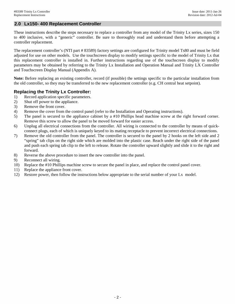
These instructions describe the steps necessary to replace a controller from any model of the Trinity Lx series, sizes 150 to 400 inclusive, with a “generic” controller. Be sure to thoroughly read and understand them before attempting a controller replacement.
The replacement controller’s (NTI part # 83589) factory settings are configured for Trinity model Ts80 and must be field adjusted for use on other models. Use the touchscreen display to modify settings specific to the model of Trinity Lx that this replacement controller is installed in. Further instructions regarding use of the touchscreen display to modify parameters may be obtained by referring to the Trinity Lx Installation and Operation Manual and Trinity LX Controller and Touchscreen Display Manual (Appendix A).
Note: Before replacing an existing controller, record (if possible) the settings specific to the particular installation from the old controller, so they may be transferred to the new replacement controller (e.g. CH central heat setpoint).
Replacing the Trinity Lx Controller: 1) Record application specific parameters. 2) Shut off power to the appliance. 3) Remove the front cover. 4) Remove the cover from the control panel (refer to the Installation and Operating instructions). 5) The panel is secured to the appliance cabinet by a #10 Phillips head machine screw at the right forward corner.
Remove this screw to allow the panel to be moved forward for easier access. 6) Unplug all electrical connections from the controller. All wiring is connected to the controller by means of quick-
connect plugs, each of which is uniquely keyed to its mating receptacle to prevent incorrect electrical connections. 7) Remove the old controller from the panel. The controller is secured to the panel by 2 hooks on the left side and 2
“spring” tab clips on the right side which are molded into the plastic case. Reach under the right side of the panel and push each spring tab clip to the left to release. Rotate the controller upward slightly and slide it to the right and forward.
8) Reverse the above procedure to insert the new controller into the panel. 9) Reconnect all wiring. 10) Replace the #10 Phillips machine screw to secure the panel in place, and replace the control panel cover. 11) Replace the appliance front cover. 12) Restore power, then follow the instructions below appropriate to the serial number of your Lx model.
#83589 Trinity Lx Controller Issue date: 2011-Jan-26 Replacement Instructions Revision date: 2012-Jul-04
- 3 -
3.0 Instructions for Serial Numbers "PRIOR TO"
Lx 150 & 150E serial numbers prior to and including 49351: Lx 200 & 400 serial numbers prior to and including 48251:
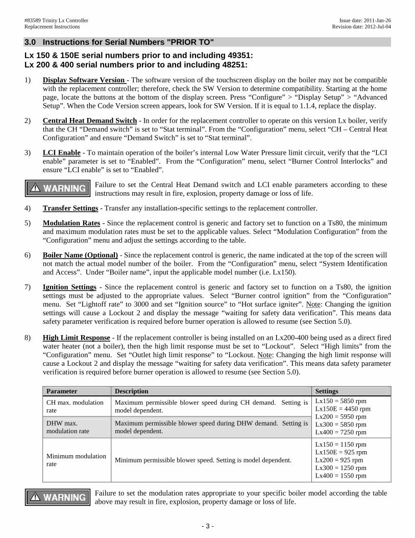
1) Display Software Version - The software version of the touchscreen display on the boiler may not be compatible with the replacement controller; therefore, check the SW Version to determine compatibility. Starting at the home page, locate the buttons at the bottom of the display screen. Press “Configure” > “Display Setup” > “Advanced Setup”. When the Code Version screen appears, look for SW Version. If it is equal to 1.1.4, replace the display.
2) Central Heat Demand Switch - In order for the replacement controller to operate on this version Lx boiler, verify that the CH “Demand switch” is set to “Stat terminal”. From the “Configuration” menu, select “CH – Central Heat Configuration” and ensure “Demand Switch” is set to “Stat terminal”.
3) LCI Enable - To maintain operation of the boiler’s internal Low Water Pressure limit circuit, verify that the “LCI enable” parameter is set to “Enabled”. From the “Configuration” menu, select “Burner Control Interlocks” and ensure “LCI enable” is set to “Enabled”.
Failure to set the Central Heat Demand switch and LCI enable parameters according to these instructions may result in fire, explosion, property damage or loss of life.
4) Transfer Settings - Transfer any installation-specific settings to the replacement controller.
5) Modulation Rates - Since the replacement control is generic and factory set to function on a Ts80, the minimum and maximum modulation rates must be set to the applicable values. Select “Modulation Configuration” from the “Configuration” menu and adjust the settings according to the table.
6) Boiler Name (Optional) - Since the replacement control is generic, the name indicated at the top of the screen will not match the actual model number of the boiler. From the “Configuration” menu, select “System Identification and Access”. Under “Boiler name”, input the applicable model number (i.e. Lx150).
7) Ignition Settings - Since the replacement control is generic and factory set to function on a Ts80, the ignition settings must be adjusted to the appropriate values. Select “Burner control ignition” from the “Configuration” menu. Set “Lightoff rate” to 3000 and set “Ignition source” to “Hot surface igniter”. Note: Changing the ignition settings will cause a Lockout 2 and display the message “waiting for safety data verification”. This means data safety parameter verification is required before burner operation is allowed to resume (see Section 5.0).
8) High Limit Response - If the replacement controller is being installed on an Lx200-400 being used as a direct fired water heater (not a boiler), then the high limit response must be set to “Lockout”. Select “High limits” from the “Configuration” menu. Set “Outlet high limit response” to “Lockout. Note: Changing the high limit response will cause a Lockout 2 and display the message “waiting for safety data verification”. This means data safety parameter verification is required before burner operation is allowed to resume (see Section 5.0).
Parameter Description Settings
CH max. modulation rate
Maximum permissible blower speed during CH demand. Setting is model dependent.
DHW max. modulation rate
Maximum permissible blower speed during DHW demand. Setting is model dependent.
Lx150 = 5850 rpm Lx150E = 4450 rpm Lx200 = 5950 rpm Lx300 = 5850 rpm Lx400 = 7250 rpm
Minimum modulation rate
Minimum permissible blower speed. Setting is model dependent.
Lx150 = 1150 rpm Lx150E = 925 rpm Lx200 = 925 rpm Lx300 = 1250 rpm Lx400 = 1550 rpm
Failure to set the modulation rates appropriate to your specific boiler model according the table above may result in fire, explosion, property damage or loss of life.
#83589 Trinity Lx Controller Issue date: 2011-Jan-26 Replacement Instructions Revision date: 2012-Jul-04
- 4 -
4.0 Instructions for Serial Numbers "AFTER"
Lx 150 & 150E serial numbers after but not including 49351: Lx 200-400 serial numbers after but not including 48251:
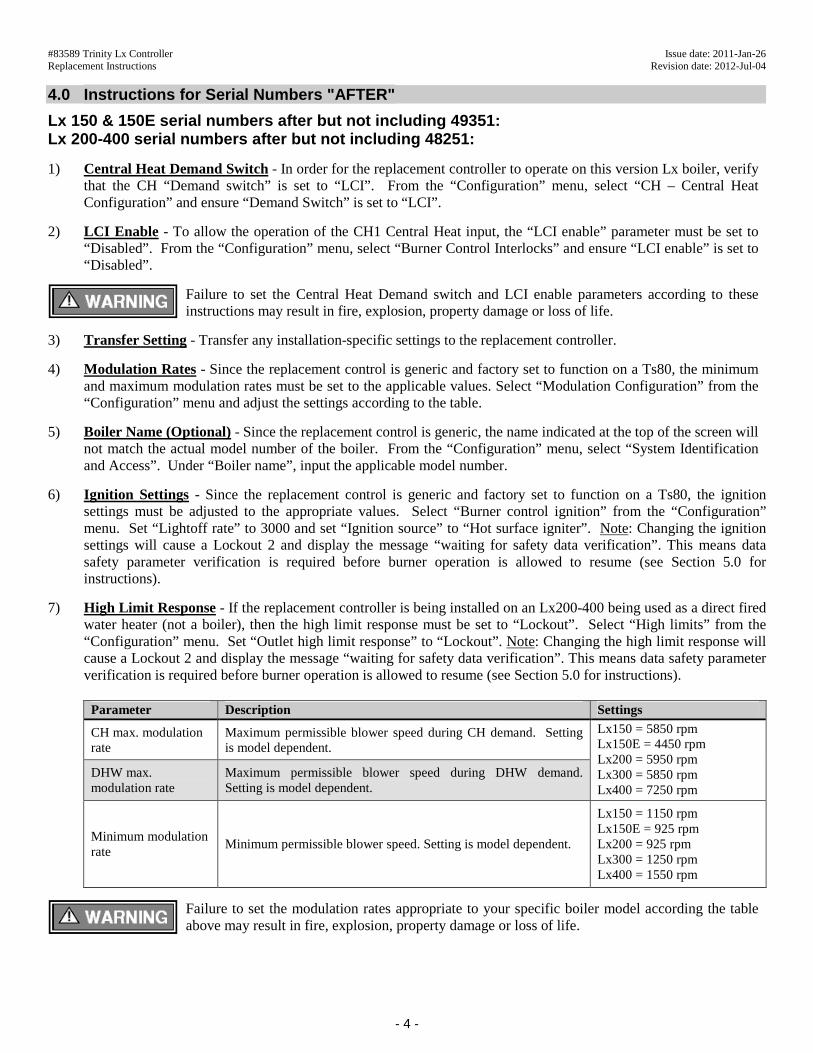
1) Central Heat Demand Switch - In order for the replacement controller to operate on this version Lx boiler, verify that the CH “Demand switch” is set to “LCI”. From the “Configuration” menu, select “CH – Central Heat Configuration” and ensure “Demand Switch” is set to “LCI”.
2) LCI Enable - To allow the operation of the CH1 Central Heat input, the “LCI enable” parameter must be set to “Disabled”. From the “Configuration” menu, select “Burner Control Interlocks” and ensure “LCI enable” is set to “Disabled”.
Failure to set the Central Heat Demand switch and LCI enable parameters according to these instructions may result in fire, explosion, property damage or loss of life.
3) Transfer Setting - Transfer any installation-specific settings to the replacement controller.
4) Modulation Rates - Since the replacement control is generic and factory set to function on a Ts80, the minimum and maximum modulation rates must be set to the applicable values. Select “Modulation Configuration” from the “Configuration” menu and adjust the settings according to the table.
5) Boiler Name (Optional) - Since the replacement control is generic, the name indicated at the top of the screen will not match the actual model number of the boiler. From the “Configuration” menu, select “System Identification and Access”. Under “Boiler name”, input the applicable model number.
6) Ignition Settings - Since the replacement control is generic and factory set to function on a Ts80, the ignition settings must be adjusted to the appropriate values. Select “Burner control ignition” from the “Configuration” menu. Set “Lightoff rate” to 3000 and set “Ignition source” to “Hot surface igniter”. Note: Changing the ignition settings will cause a Lockout 2 and display the message “waiting for safety data verification”. This means data safety parameter verification is required before burner operation is allowed to resume (see Section 5.0 for instructions).
7) High Limit Response - If the replacement controller is being installed on an Lx200-400 being used as a direct fired water heater (not a boiler), then the high limit response must be set to “Lockout”. Select “High limits” from the “Configuration” menu. Set “Outlet high limit response” to “Lockout”. Note: Changing the high limit response will cause a Lockout 2 and display the message “waiting for safety data verification”. This means data safety parameter verification is required before burner operation is allowed to resume (see Section 5.0 for instructions).
Parameter Description Settings
CH max. modulation rate
Maximum permissible blower speed during CH demand. Setting is model dependent.
DHW max. modulation rate
Maximum permissible blower speed during DHW demand. Setting is model dependent.
Lx150 = 5850 rpm Lx150E = 4450 rpm Lx200 = 5950 rpm Lx300 = 5850 rpm Lx400 = 7250 rpm
Minimum modulation rate
Minimum permissible blower speed. Setting is model dependent.
Lx150 = 1150 rpm Lx150E = 925 rpm Lx200 = 925 rpm Lx300 = 1250 rpm Lx400 = 1550 rpm
Failure to set the modulation rates appropriate to your specific boiler model according the table above may result in fire, explosion, property damage or loss of life.
#83589 Trinity Lx Controller Issue date: 2011-Jan-26 Replacement Instructions Revision date: 2012-Jul-04
- 5 -
5.0 Instructions for Safety Data Verification
Sola Reset Button - To complete Safety Parameter Verification, you must physically press the Reset button on the Sola controller which is located in the wiring control panel. To do this,
remove the front cover on the appliance. Locate the control panel at the bottom of the unit, and remove the cover. HINT: Do this before starting verification as you will only have 30 seconds to press the Reset button once you begin. See Figure 7 for exact location of Reset button.
Follow the steps to verify safety parameters and reset the controller: 1) Starting at the Home page, press the Lockout 2 warning near the bottom of the screen and clear the lockout. 2) Return to Home page, locate the buttons at the bottom of the display screen to navigate through Safety Data
Verification. Press “Configure” > “Verify” > “Login” (if you haven’t already; Hint: Password is “sola”). 3) Follow the prompts on the various Safety Parameter Verification screens to verify changes. 4) When parameters are confirmed, a hard reset of the controller will be required (see Figure 6). 5) Press the Reset button on the Sola controller as shown to enable normal burner operation (see Figure 7). If more information is required, see the Lx Controller Manual Appendix A or call NTI Tech Support at 1-800-688-2575.
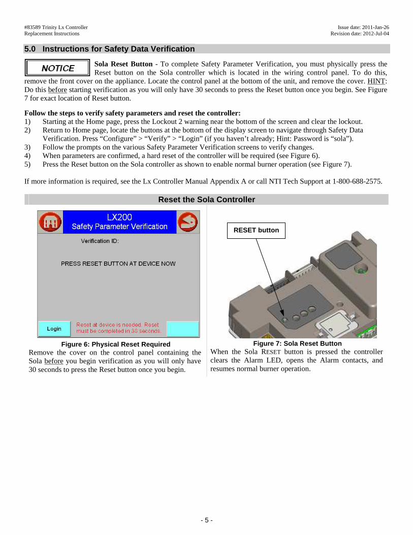
Reset the Sola Controller
Figure 6: Physical Reset Required Remove the cover on the control panel containing the Sola before you begin verification as you will only have 30 seconds to press the Reset button once you begin.
Figure 7: Sola Reset Button When the Sola RESET button is pressed the controller clears the Alarm LED, opens the Alarm contacts, and resumes normal burner operation.
RESET button