8251A programmable Communication Interface · PDF fileSignals of 8251 CS –Chip Select :...
63
DATA COMMUNICATION
Transcript of 8251A programmable Communication Interface · PDF fileSignals of 8251 CS –Chip Select :...

DATA COMMUNICATION
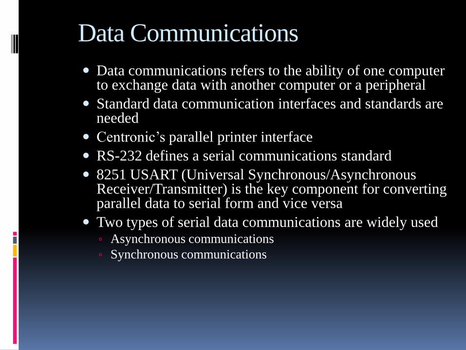
Data Communications
Data communications refers to the ability of one computer to exchange data with another computer or a peripheral
Standard data communication interfaces and standards are needed
Centronic’s parallel printer interface
RS-232 defines a serial communications standard
8251 USART (Universal Synchronous/Asynchronous Receiver/Transmitter) is the key component for converting parallel data to serial form and vice versa
Two types of serial data communications are widely used◦ Asynchronous communications
◦ Synchronous communications

Parallel/Serial Transmissions

Communication Modes
When data is transmitted between two piece of
equipment, 3 modes of communication are used
Simplex
Data is transmitted in one direction only
Half Duplex
This is used when to devices wants information alternatively,
but one after another
Full Duplex
This is used when data is to be exchanged between two
devices in both directions simultaneously

Communication Modes
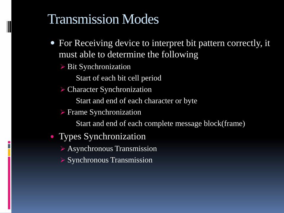
Transmission Modes
For Receiving device to interpret bit pattern correctly, it
must able to determine the following
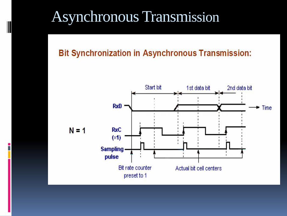
Bit Synchronization
Start of each bit cell period
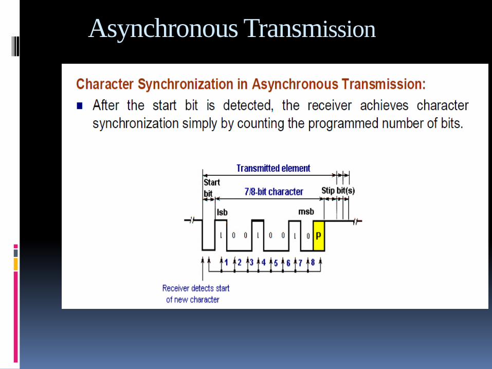
Character Synchronization
Start and end of each character or byte
Frame Synchronization
Start and end of each complete message block(frame)
Types Synchronization
Asynchronous Transmission
Synchronous Transmission

Asynchronous Transmission
In Asynchronous Transmission receiver clock runs(RxC) in unsynchronized with respect to the incoming signal(RxD)
Additional start and stop bits are added in character(byte) data
State of signal on transmission line between characters is idle

Asynchronous communications
– The start bit is always one bit and always a 0. (low)
– The stop bit can be one or two bits, and is 1 (high).
ASCII character "A", binary 0100 0001, framed between the start bit and 2 stop bits.
• In asynchronous communications, the data, such as
ASCII characters, are packed between a start bit and a
stop bit, a process called framing.

Asynchronous Transmission

Asynchronous Transmission

Asynchronous Transmission

Asynchronous Transmission
Asynchronous Transmission

Asynchronous Transmission

Asynchronous Transmission
Asynchronous Transmission

Synchronous Transmission

Synchronous Transmission

Synchronous Transmission

RS232
For compatibility in data communication equipment, an interfacing standard called RS232 was set by the Electronics Industries Association (EIA) in 1960.
Todays most widely used serial I/O interface standard
Pins and their labels for the
RS232 cable, which is
commonly referred to as the
DB-9 connector.
Fig DB9 9-Pin Connector

Digital Data Transmission using MODEM

Digital Data Transmission using MODEM

Sequence of Modem Control Signals
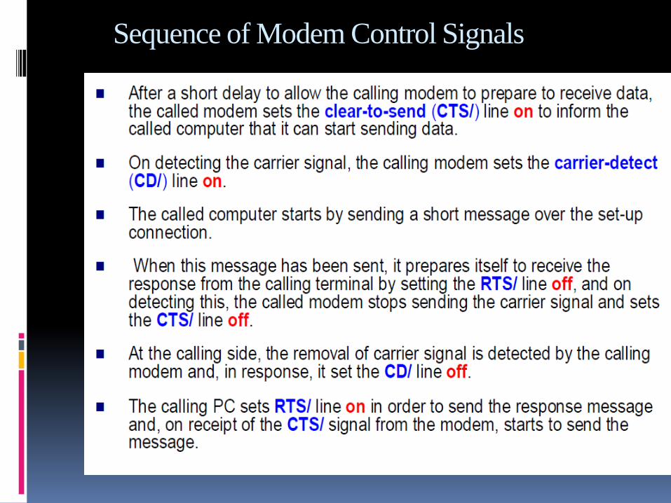
Sequence of Modem Control Signals

Digital Data Transmission using MODEM

8251 PROGRAMMABLE
COMMUNICATION INTERFACE

Introduction
8251 is a USART (Universal Synchronous Asynchronous Receiver Transmitter) for serial data communication.
Programmable peripheral designed for synchronous /asynchronous serial data communication, packaged in a 28-pin DIP.
Receives parallel data from the CPU & transmits serial data after conversion.
Also receives serial data from the outside & transmits parallel data to the CPU after conversion.

Block diagram of the 8251 USART

Pin diagram

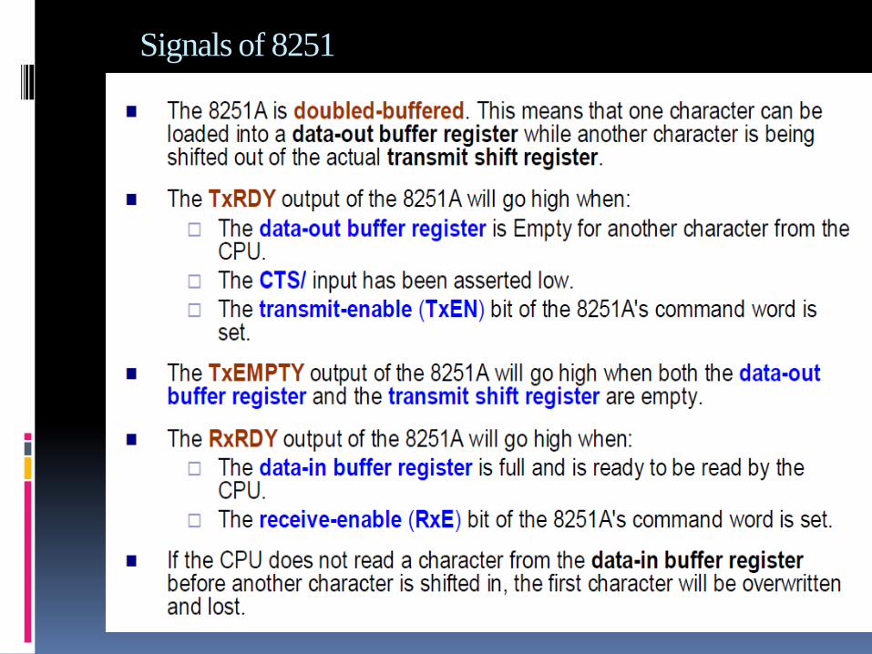
Signals of 8251
CS – Chip Select : When signal goes low, the 8251A is selected by the MPU for communication.
C/D – Control/Data : When signal is high, the control or status register is addressed; when it is low, data buffer is addressed. (Control register & status register are differentiated by WR and RD signals)
WR : When signal is low, the MPU either writes in the control register or sends output to the data buffer.
RD : When signal goes low, the MPU either reads a status from the status register or accepts data from data buffer.
RESET : A high on this signal reset 8252A & forces it into the idle mode.
CLK : Clock input, usually connected to the system clock for communication with the microprocessor.
Signals of 8251

Signals of 8251

Sections of 8251
Data Bus buffer
Read/Write Control Logic
Modem Control
Transmitter
Receiver
1. Data Bus Buffer
D0-D7 : 8-bit data bus used to read or write status,
command word or data from or to the 8251A

2. Read/Write Control logic
Includes a control logic, six input signals &
three buffer registers: Data register, control
register & status register.
Control logic : Interfaces the chip with MPU,
determines the functions of the chip according
to the control word in the control register &
monitors the data flow.

3. Modem Control
DSR - Data Set Ready : Checks if the Data Set is ready when communicating with a modem.
DTR - Data Terminal Ready : Indicates that the device is ready to accept data when the 8251 is communicating with a modem.
CTS - Clear to Send : If its low, the 8251A is enabled to transmit the serial data provided the enable bit in the command byte is set to ‘1’.
RTS - Request to Send Data : Low signal indicates the modem that the receiver is ready to receive a data byte from the modem.

4. Transmitter section
Accepts parallel data from MPU & converts them into serial data.
Has two registers: Buffer register : To hold eight bits
Output register : To convert eight bits into a stream of serial bits.
Transmit control
Output Register
Transmitter Buffer
TxD
TxRDY
TxE

The MPU writes a byte in the buffer register.
Whenever the output register is empty; the contents of buffer register are transferred to output register.
Transmitter section consists of three output & one input signals TxD - Transmitted Data Output : Output signal to transmit
the data to peripherals
TxC - Transmitter Clock Input : Input signal, controls the rate of transmission.
TxRDY - Transmitter Ready : Output signal, indicates the buffer register is empty and the USART is ready to accept the next data byte.
TxE - Transmitter Empty : Output signal to indicate the output register is empty and the USART is ready to accept the next data byte.

5. Receiver Section
Accepts serial data on the RxD pin and converts them to parallel data.
Has two registers : Receiver input register
Buffer register
Receive Buffer
Receive control
Input Register
RxRDY
RxC
RxD

When RxD goes low, the control logic assumes it is a start bit, waits
for half bit time, and samples the line again. If the line is still low, the
input register accepts the following data, and loads it into buffer
register at the rate determined by the receiver clock.
RxRDY - Receiver Ready Output: Output signal, goes high when the
USART has a character in the buffer register & is ready to transfer it
to the MPU.
RxD - Receive Data Input : Bits are received serially on this line &
converted into a parallel byte in the receiver input register.
RxC - Receiver Clock Input : Clock signal that controls the rate at
which bits are received by the USART.

Control Register
16-bit register for a control word consist of two independent bytes namely mode word & command word.
Mode word : Specifies the general characteristics of operation such as baud, parity, number of bits etc.
Command word : Enables the data transmission and reception.
Register can be accessed as an output port when the Control/Data pin is high.

Status register Checks the ready status of the peripheral.
Status word in the status register provides the
information concerning register status and transmission
errors.
Data register Used as an input and output port when the C/D is low
CS C/D WR RD Operation
0
0
0
0
1
0
0
1
1
1
0
0
1
0
1
1
0
MPU reads data from data buffer
MPU writes data from data buffer
MPU writes a word to control register
MPU reads a word from status register
Chip is not selected for any operation

Interfacing 8251 to 8088

8251 Communication Interface
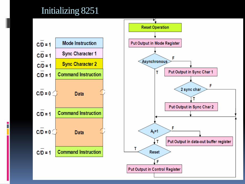
Initializing 8251

Initializing 8251
To implement serial communication the MPU must inform the 8251 about the mode, baud, stop bits, parity etc. A set of control words must be loaded.
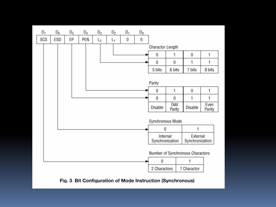
Mode Words
Specifies general characteristics of the operation.
Command Words
Enables the data transmission and/or reception
Status Word provides the information concerning register status and transmission errors.
Any control word written into the control register after a mode word is interpreted as a command word; that means a command word can be changed anytime, however 8251 should be reset prior to writing a Mode word.
8251 can be reset internally by using the Internal Reset Bit D6.

8251 Mode Word

8251 Command Word

8251 Command Word
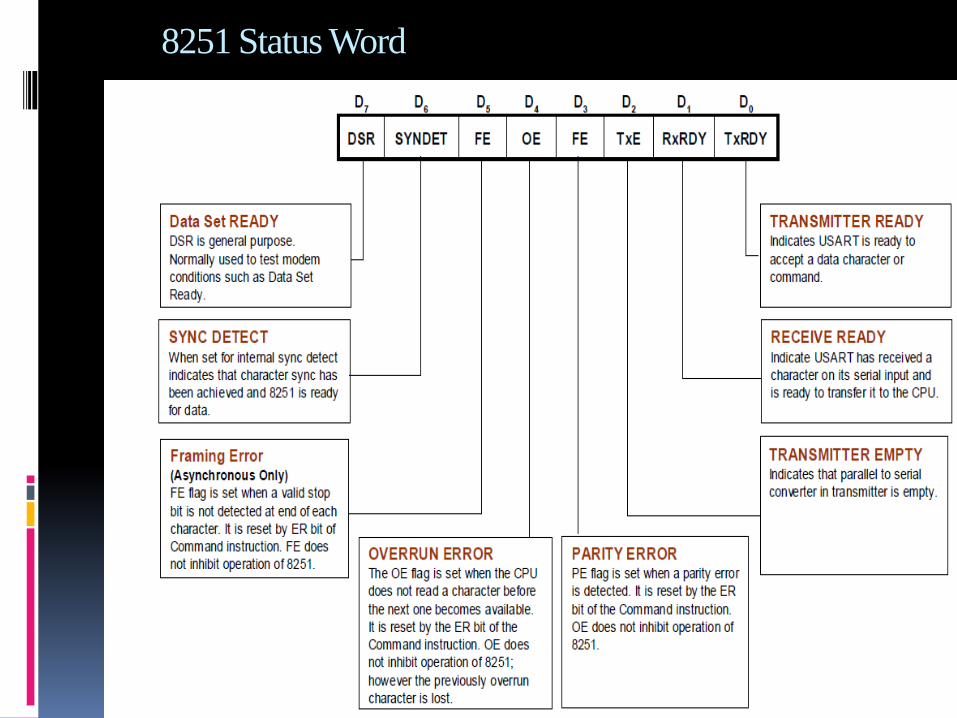
8251 Status Word

Simple Serial I/O Procedures
Read
start
Check RxRDY
Is it logic 1?
Read data register*
end
Yes
No
* This clears RxRDY
Write
start
Check TxRDY
Is it logic 1?
Write data register*
end
Yes
No
* This clears TxRDY


8251 A Serial Communication Interface
• The 8251A internally interprets the C/D,RD and WR
signals as follow:
• Whether the mode, control or sync character register is
selected depends on the accessing sequence.
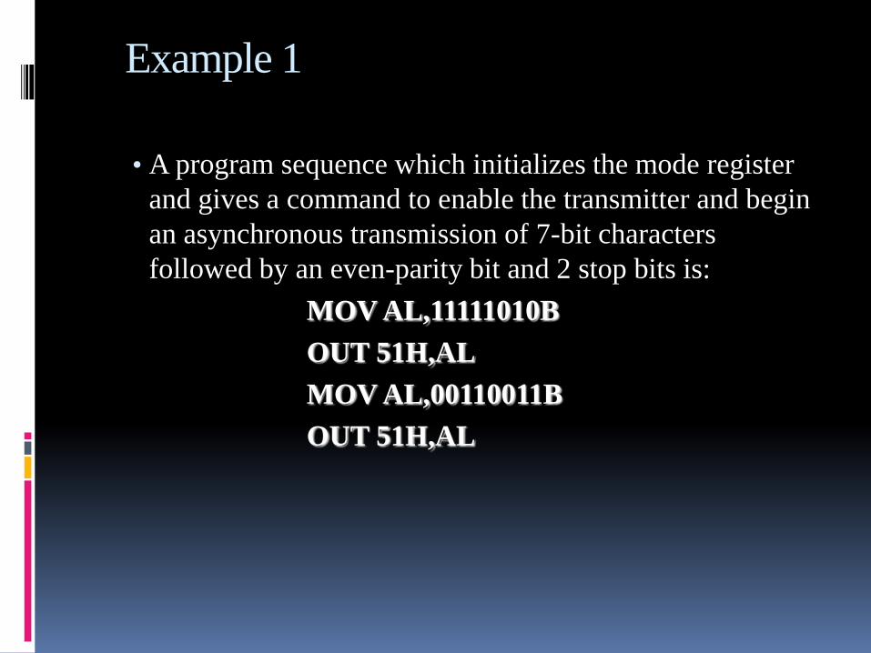
Example 1
• A program sequence which initializes the mode register
and gives a command to enable the transmitter and begin
an asynchronous transmission of 7-bit characters
followed by an even-parity bit and 2 stop bits is:
MOV AL,11111010B
OUT 51H,AL
MOV AL,00110011B
OUT 51H,AL

Example 2• This sequence assumes that the mode and control registers
are at address 51H and the clock frequencies are to be 16
times the corresponding baud rates.
The sequence:
MOV AL,00111000B
OUT 51H,AL
MOV AL,16H
OUT 51H,AL
OUT 51H,AL
MOV AL,10010100B
OUT 51H,AL
would cause the same 8251A to be put in synchronous mode
and to begin searching for two successive ASCII sync
characters

Format of the status register

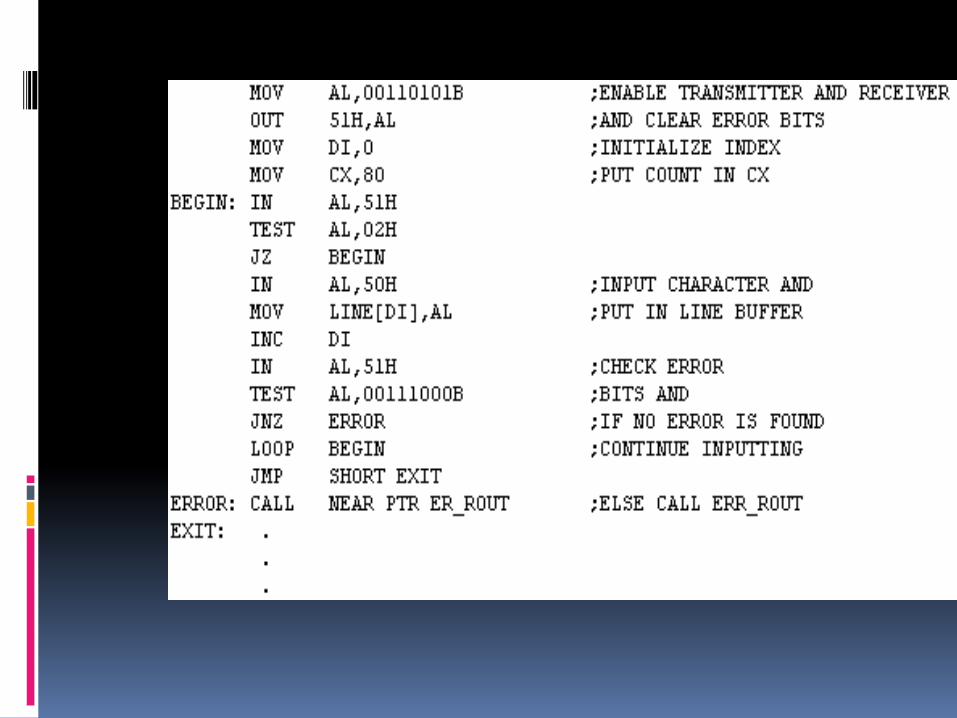
Example 3
• A typical program sequence which uses
programmed I/O to input 80 characters from the
8251A, whose data buffer register's address is
0050, and put them in the memory buffer
beginning at LINE.

Example 4
1000 000 0 : data register address: xx80h
1000 000 1: control or status register address: xx81h
Mode word:
◦ 2 stop bits. no parity, 8 bit characters. Baud rate factor of 16 (1200 Kbps)
◦ 1110 1110 =EEh
Command Word:
0001 0101 = 15h ; enable TxRDY and RxRDYand reset all flags first

INIT8251:MOV AL,0EEh
OUT 81h, AL
MOV AL, 15h
OUT 81h, AL
CHKRX:IN AL,81h
ROR AL,1
ROR AL,1
JNC CHKRX
IN AL,80h
NOT AL
MOV BL,AL
CHKTX:IN AL,81h
ROR AL,1
JNC CHKTX
OUT 80h,AL
JMP CHKRX
Initialize the Mode Word andCommand Word
Receive Ready?
If Ready get data
Send data if the T buffer register is available

Thank You