§81 -1504(10), 81 1504(30), 81-1505(8)...
49
NEBRASKA ADMINISTRATIVE CODE NEBRASKA DEPARTMENT OF ENVIRONMENT AND ENERGY TITLE 123 - RULES AND REGULATIONS FOR THE DESIGN, OPERATION AND MAINTENANCE OF WASTEWATER WORKS NUMERICAL TABLE OF CONTENTS CHAPTER NAME OF CHAPTER STATUTORY AUTHORITY 1 Definitions 2 Application of Regulations §81-1504(10); 81-1504(20); 81-1505(8) 3 Construction Permits §81-1505(8) 4 Prohibited New Construction §81-1505(8) 5 Design Standards §81-1504(10) 6 Approval of Alternative Designs §81-1504(10) 7 Submission of Engineering Documents §81-1504(10), 81-1504(30), 81-1505(8) 8 Construction Plans and Specifications §81-1504(10) 9 Construction of Wastewater Works §81-1504(10) 10 Abandonment of Wastewater Works §81-1505(8) 11 Operation and Maintenance of §81-1504(12), 81-1505(8) Wastewater Works Appendix A Construction Permit Application Form
Transcript of §81 -1504(10), 81 1504(30), 81-1505(8)...

NEBRASKA ADMINISTRATIVE CODE
NEBRASKA DEPARTMENT OF ENVIRONMENT AND ENERGY
TITLE 123 - RULES AND REGULATIONS FOR THE DESIGN, OPERATION AND MAINTENANCE OF
WASTEWATER WORKS
NUMERICAL TABLE OF CONTENTS
CHAPTER NAME OF CHAPTER STATUTORY AUTHORITY 1 Definitions 2 Application of Regulations §81-1504(10); 81-1504(20); 81-1505(8) 3 Construction Permits §81-1505(8) 4 Prohibited New Construction §81-1505(8) 5 Design Standards §81-1504(10) 6 Approval of Alternative Designs §81-1504(10) 7 Submission of Engineering Documents §81-1504(10), 81-1504(30), 81-1505(8)
8 Construction Plans and Specifications §81-1504(10) 9 Construction of Wastewater Works §81-1504(10) 10 Abandonment of Wastewater Works §81-1505(8) 11 Operation and Maintenance of §81-1504(12), 81-1505(8)
Wastewater Works
Appendix A Construction Permit Application Form

NEBRASKA ADMINISTRATIVE CODE
TITLE 123 – NEBRASKA DEPARTMENT OF ENVIRONMENT AND ENERGY Chapter 1 – DEFINITIONS 001 “Abandonment” means the permanent removal from service of a wastewater works. 002 “Alternative design” means a design for a wastewater structure, prepared by a professional engineer, to provide safe and reliable service, when it is impractical to meet the design standards for wastewater works contained in State regulations. 003 “As-built drawings” or “Record drawings” mean drawings that are prepared during or following construction to describe the completed construction, including all changes made during construction. 004 “BOD5” means the five-day measure of the pollutant parameter biochemical oxygen demand (BOD). 005 “Bypass” means the intentional diversion of waste streams from any portion of a treatment facility. 006 “Combined sewer” means a wastewater collection system that is designed and constructed to transport both sanitary wastewater (domestic, commercial and industrial wastewaters) and storm water through a single pipe to a publicly owned treatment works. 007 “Complete retention” means a type of wastewater treatment facility that does not discharge to waters of the state, to subsurface disposal systems, or to wastewater irrigation systems, but uses evaporation, evapotranspiration, and seepage within allowable limits, to dispose of the wastewater. 008 “Constructed wetlands” for the specific purposes of this title, means a manmade treatment basin, planted with emergent plant species, designed and constructed according to engineering standards to treat wastewater. 009 “Construction permit” means a written authorization from the Director to construct, install, change or make alterations in, or additions to, a wastewater works. 010 “Controlled discharge lagoon” means a discharging wastewater lagoon system operated to store wastewater for extended periods and to periodically discharge treated effluent in accordance with permits. 011 “Cross connection” means any physical arrangement whereby a potable water supply system is connected, directly or indirectly, with any other water system, including a wastewater system.
Title 123 Chapter 1 012 “Curvilinear sewer” means a sanitary sewer section where the horizontal alignment is curved. 013 “Design standards” or “Standards” means the minimum engineering requirements for the design of wastewater works. 014 “Discharge” or “Discharging” for the specific purposes of this title, means the introduction of wastewater, either treated or untreated, from a point source into any part of a collection system, storage facility, or wastewater treatment unit; or to waters of the State or the natural environment. 015 “Domestic wastewater” means human body waste and household type wastes including bath and toilet wastes, laundry wastes, kitchen wastes, and other similar wastes. 016 “Facultative lagoon” means a shallow wastewater lagoon where biological treatment from both aerobic and anaerobic microorganisms occurs and that relies on algae and wind action to provide oxygen for aerobic processes. 017 “Freeboard” means the vertical distance between the design full liquid level and the level at which an uncontrolled overflow from a wastewater lagoon or other wastewater treatment unit would occur. 018 “Force main” means a wastewater pipe that conveys wastewater by the force of pumping pressure. 019 “Gravity sewer” means a wastewater collection pipe that slopes towards the destination point and conveys wastewater by the force of gravity. 020 “Grinder pump” means a pump, equipped with a shredding ring and cutter bar that grinds wastewater solids into small particles creating a wastewater slurry. 021 “Ground water” means water occurring beneath the surface of the ground that fills available openings in rock or soil materials such that they may be considered saturated. 022 “Industrial” means a production, food processing, manufacturing, or similar establishment that generates wastewater. 023 “Inverted siphon” means a depressed sewer structure, having at least two barrels, that uses hydraulic head pressure on the downward sewer section to force wastewater up the rising section.

Title 123 Chapter 1 024 “Land application” means the controlled application of effluent onto the land surface to achieve a designed degree of treatment through natural, physical, chemical and biological processes within the plant-soil-water matrix. 025 “Lift station” means a facility housing wastewater pumps and their appurtenances. 026 “Liner” means the compacted soil or other material used to seal the bottom or sides of a wastewater lagoon, sand filter, constructed wetland, or other wastewater treatment unit so that the seepage rate of liquids from the treatment unit into the surrounding soil is controlled. 027 “Livestock truck wash” means a facility that washes trucks used for hauling livestock. 028 “Livestock waste control facility” is defined in NAC Title 130, Livestock Waste Control Regulations, Chapter 1. 029 “Mechanical WWTF” or “Mechanical plant” means a wastewater treatment facility that uses separate treatment units for grit removal, physical settling, biological treatment, clarification, sludge treatment, and disinfection, as applicable, where treatment processes are enhanced by mechanical or electrical devices. 030 “National Pollutant Discharge Elimination System Permit” or “NPDES permit” means any permit issued by the Director, after June 12, 1974, to regulate the discharge of pollutants pursuant to NAC Title 119, Rules and Regulations Pertaining to the Issuance of Permits under the National Pollutant Discharge Elimination System and Sections 402, 307, 318, and 405 of the Clean Water Act, 33 U.S.C. §1251 et seq. . 031 “100-year flood” means the flood having a one per cent chance of being equaled or exceeded in magnitude in any given year. 032 “On-site wastewater treatment systems” means any system of piping, treatment devices, or other appurtenances that convey, store, treat, or dispose of domestic or nondomestic wastewater, but not including wastewater from a livestock waste control facility, on the property where it originates, or on nearby property under the control of the user, which system is not connected to a public sewer system. An on-site wastewater treatment system begins at the end of the building drain. All systems except septic systems are limited to a maximum size of 1000 gallons per day to be considered an on-site wastewater treatment system. The word “onsite” used in this Title is equivalent to the word “on-site”. 033 “Operator” means any person who regularly makes recommendations or is responsible for process control decisions at a wastewater treatment facility. Operator shall not include a person whose duties are limited solely to laboratory testing or maintenance or who exercises general or indirect supervision only.
Title 123 Chapter 1 034 “Operation and maintenance manual” means a manual that contains the information necessary to operate and maintain a wastewater works. 035 “Overflow structure” means a diversion structure in a wastewater collection system that discharges wastewater to the ground surface or to waters of the State, circumventing the wastewater treatment facility, usually during high flow conditions. 036 “Owner” means the owner of any facility or activity subject to regulation under this title. 037 “Plans and specifications” means the construction drawings prepared by an engineer, showing the design, location, and dimensions of the project and the written requirements for materials, equipment, construction standards and workmanship that fully describe the construction requirements. 038 “Potable water” means water that is safe for human consumption as determined in accordance with NAC, Title 179, Public Water Systems, Chapter 2-002. 039 “Pretreatment facility ” means a wastewater treatment facility owned by a commercial or industrial user which discharges pretreated wastewater to a publicly owned treatment works. 040 “Primary cells” means the initial cells in a lagoon system that receive untreated wastewater. 041 “Primary treatment” means a physical treatment process that removes particulate solids from wastewater by settling. 042 “Professional engineer” means a person who is licensed as a professional engineer by the Nebraska Board of Engineers and Architects. The board may designate a professional engineer, on the basis of education, experience, and examination, as being licensed in a specific discipline or branch of engineering signifying the area in which the professional engineer has demonstrated competence. 043 “Public water system” is defined in Neb. Rev. Stat. §77-5301(10)(a) of the Nebraska Safe Drinking Water Act. 044 “Rapid infiltration cell” means a manmade basin designed and constructed according to engineering standards to provide treatment to wastewater as it percolates through soil in a cycle of dosing and drying periods. 045 “Raw wastewater” means wastewater that is untreated. 046 “Sanitary sewer” or “Sewer” means pipes, conduits, manholes, cleanouts, and all other constructions, devices, appurtenances, and facilities used for collecting or transporting wastewater to an
Title 123 Chapter 1 ultimate point for storage, treatment, or disposal. This does not include storm sewers conveying storm water runoff. 047 “Satellite lift station” means a wastewater pumping station located within the wastewater collection system, excluding pumping units having a flow less than 2000 gallons per day and serving four or fewer service connections, and also excluding pumping stations that are part of a wastewater treatment facility. 048 “Secondary cells” means lagoon cells that receive wastewater from primary lagoon cells. 049 “Seepage rate” means the rate of water loss through the liner of a wastewater lagoon or the liner of other wastewater storage or treatment units. 050 “Service connection” means a pipe transporting wastewater from an individual building to a sanitary sewer main. 051 “Sewage sludge” or “Sludge” is defined in NAC, Title 119, Chapter 1. 052 “Small diameter gravity sewer” means a wastewater collection system utilizing settling tanks at each service connection and variable grade sewer pipes at least four inches in diameter to transport wastewater to a wastewater treatment facility. 053 “Small diameter pressure sewer” means a pressurized wastewater collection system where service connections use septic tank effluent pumps or grinder pumps to pressurize the sewer system. 054 “Solids settling pit” means a concrete treatment unit where wash water from a truck wash facility has settleable solids and/or floatable solids separated from the wash water, and allows the liquid wastewater to flow through to a wastewater lagoon. 055 “Solids storage unit” for the specific purpose of this title means a part of a livestock truck wash where the solids removed from a solids settling pit are stored and dried so that liquids drain back to the wastewater works. 056 “Standard specifications and plate drawings” means specifications and drawings that have been approved for general use by a municipality or engineering firm for the construction of sanitary sewers and appurtenances designed to be built within the municipal jurisdiction or by the clients of the engineering firm. 057 “Storm sewer” means a collection system designed and constructed to collect storm water runoff, snow melt runoff, and surface runoff and drainage. 058 “Synthetic liner” means a man-made membrane that is installed in a wastewater structure to restrict seepage.

Title 123 Chapter 1 059 “Vegetated submerged bed constructed wetlands” means a shallow treatment basin where wastewater is treated as it moves horizontally through gravel media in which wetland plants grow, and the water surface is controlled below the top surface of the gravel media. 060 “Wash pad” means an area designed and constructed to conduct washing activities and to contain the wastewater generated by the washing activity. 061 “Wastewater” means the combination of the liquid or water carried wastes removed from residences, institutions, and commercial and industrial establishments, together with such ground water, surface water, and storm water as may be present. 062 “Wastewater collection systems” means pipes, conduits, wastewater pumping stations, force mains, inverted siphons, and all other constructions, devices, appurtenances, and facilities used for collecting or transporting wastes to an ultimate point for storage, treatment, or disposal. 063 “Wastewater cell” or “Cell” means a lagoon, basin, pond, constructed wetland, sand filter or other excavation, usually with earthen dikes, that is designed and constructed as part of a wastewater treatment facility. 064 “Wastewater lagoon” or “lagoon” means a detention, storage, or holding pond, usually with earthen dikes, designed and constructed to treat or store wastewater. 065 “Wastewater solids” means any solid or semi-solid material contained in or removed from a wastewater stream, including solids accumulated from washing operations at a truck wash facility. 066 “Wastewater treatment facility” or “WWTF” means a group or assemblage of processes, devices and structures for the treatment or removal of pollutants from wastewater. 067 “Wastewater works” shall mean facilities for collecting, conveying, storing, pumping and treating wastewater and the disposal of the treated effluent and sludges. 068 “Water main” means a pressurized water pipe that is part of a system providing potable water to the public, but is not a privately owned service connection. 069 “Water well” is define in Neb. Rev. Stat. §46-601.01. 070 The following terms are defined in Neb. Rev. Stat. §81-1502: Department, Director, Person, and Waters of the State. Legal Citation: Title 123, Ch. 1, Nebraska Department of Environment and Energy

NEBRASKA ADMINISTRATIVE CODE
TITLE 123 – NEBRASKA DEPARTMENT OF ENVIRONMENT AND ENERGY Chapter 2 – APPLICATION OF REGULATIONS 001 All requirements of this title apply to wastewater works that are constructed, installed, modified, or have additions made on or after July 26, 2006. 002 Chapters 10 and 11 of this title apply to wastewater works that were constructed, installed, modified, or had additions made before July 26, 2006. 003 Wastewater works that were constructed, installed, modified, or had additions made without a valid construction permit, on or after June 22, 1972, will be upgraded to meet current design standards. The owner will submit to the Department an engineering evaluation of the wastewater facility, prepared by a professional engineer, and correct any deficiencies identified during the Department’s review of the engineering evaluation. 004 Permits issued under these regulations are exempt from financial responsibility requirements in Neb. Rev. Stat. §81-1505(21)(a). 005 The design standards in this title are minimum standards. Meeting these minimum standards does not release the design engineer or the owner from the responsibility of designing and constructing fully operational wastewater works. Enabling Legislation: Neb. Rev. Stat. §81-1504(10); 81-1504(20); 81-1505(8) Legal Citation: Title 123, Ch. 2, Nebraska Department of Environment and Energy

NEBRASKA ADMINISTRATIVE CODE
Title 123 - NEBRASKA DEPARTMENT OF ENVIRONMENT AND ENERGY Chapter 3 – CONSTRUCTION PERMITS 001 No person shall construct, install, modify, or make additions to a wastewater works until a construction permit is issued authorizing the project. A construction permit will be issued after review and approval of the construction plans, specifications, and other required planning and design information. 002 The following types of projects are exempt from the construction permit requirements of this title:
002.01 The replacement of sanitary sewer sections with sewers of the same diameter, elevation, slope, and alignment, if the replacement sewer meets all applicable setback requirements to water wells, water mains, and other water utility structures, including those stated in Chapter 5. 002.02 The replacement of electric service lines, meters, electrical panels and controls, circuit breakers, and the electrical wiring serving a wastewater works. 002.03 The replacement of mechanical equipment with equivalent equipment of the same size, type, and capacity such that all treatment units and processes remain unchanged. 002.04 The performance of routine plant maintenance, including replacing worn parts, making structural repairs, and rebuilding existing equipment. 002.05 The construction of on-site wastewater treatment systems governed by Title 124, Rules and Regulations for the Design, Operation, and Maintenance of On-Site Wastewater Treatment Systems. 002.06 The construction of livestock waste control facilities governed by Title 130, Livestock Waste Control Regulations. 002.07 The installation of supervisory control and data acquisition (SCADA) control systems. 002.08 The construction of separate municipal storm sewers.
002.09 The construction of sanitary sewer service connections for individual buildings. 002.10 The construction of commercial or industrial WWTF if the following three conditions are met:
002.10A The treated wastewater discharges to a municipal sanitary sewer system,
Title 123 Chapter 3
002.10B The facility is not required to obtain a NPDES permit under the Clean Water Act, 33 U.S.C. 1251 et seq., and 002.10C The treatment facilities do not include earthen wastewater lagoons or other earthen structures.
003 A construction permit will be valid only if construction is started within one year and is completed within three years from the date of approval. Written requests may be submitted for reauthorization or time extensions and may be subject to any additional requirements of these or such future regulations as are in effect on the date of reauthorization. Enabling Legislation: Neb. Rev. Stat. §81-1505(8) Legal Citation: Title 123, Ch. 3, Nebraska Department of Environment and Energy

NEBRASKA ADMINISTRATIVE CODE
Title 123 - NEBRASKA DEPARTMENT OF ENVIRONMENT AND ENERGY Chapter 4 – PROHIBITED NEW CONSTRUCTION 001 New construction of the following facilities is prohibited:
001.01 Combined sewers, except for modifications to existing combined sewers that are necessary to maintain service in the system or where a modification is an intermediate step in an overall program to separate existing combined sewer systems. 001.02 WWTF outfall structures designed to discharge directly to impounded surface waters listed in Title 117, Nebraska Surface Water Quality Standards. 001.03 Cross connections between potable water supplies and wastewater appurtenances that could allow wastewater to contaminate the potable water supply. 001.04 Inflow structures, including downspouts, piping systems, trenches and storage structures, that discharge water from roof drains, exterior storm water drains, ground water or foundation drains, or that discharge single-pass non-contact cooling water to a public sanitary sewer system, unless it is authorized by permit or regulation. This rule does not prohibit maintenance work, replacements, modifications or changes to existing inflow structures if no new areas or sources of inflow water are connected to the public sanitary sewer.
002 No person will be permitted to construct extensions to a sanitary sewer system if the receiving WWTF is not capable of meeting requirements imposed by a permit issued under Title 119, Rules and Regulations Pertaining to the Issuance of Permits Under the National Pollutant Discharge Elimination System, or where the WWTF is already loaded at or near its design capacity and cannot adequately treat or store the proposed additional flow, unless the person obtains an enforceable order from the Department authorizing the construction. This does not apply to interceptor sewers or relief sewers that will have no direct service connections. Enabling Legislation: Neb. Rev. Stat. §81-1505(8) Legal Citation: Title 123, Ch. 4, Nebraska Department of Environment and Energy
NEBRASKA ADMINISTRATIVE CODE
Title 123 - NEBRASKA DEPARTMENT OF ENVIRONMENT AND ENERGY Chapter 5 – DESIGN STANDARDS AND SPECIFICATIONS The Department gives credit to the Recommended Standards for Wastewater Facilities, prepared by the Great Lakes-Upper Mississippi River Board of State and Provincial Public Health and Environmental Managers as the primary source for the design standards included in Chapter 5. 001 General Design Criteria Requirements
001.01 Wastewater works will be designed in accordance with the design standards listed in this Title. Where specific standards are not included in this Title, the design engineer is to submit a proposed design to the Department for review and approval. The Department will consider approving designs that follow generally accepted engineering guidelines and standards published by national engineering societies, federal environmental agencies, public health boards, or in engineering textbooks used by accredited university engineering programs. 001.02 The hydraulic design of wastewater works will be based on historical flow records. In the absence of flow records, an average daily flow of at least 100 gallons per person per day from domestic sources is to be used. This includes a normal allowance for infiltration and inflow. Flow from commercial, institutional, and industrial sources is to be estimated from similar facilities that have historic flow records. 001.03 The organic loading rates used for designing wastewater treatment facilities is to be based on historical influent data, if at least one year of monthly sampling data exists. In the absence of such data, the design of wastewater treatment facilities are to use an organic loading rate of at least 0.17 pounds of five-day biochemical oxygen demand (BOD5) per person per day and a suspended solids loading rate of at least 0.20 pounds per person per day from domestic sources. The organic loading from commercial, institutional, and industrial sources is to be estimated from similar facilities that have loading records. 001.04 The design of discharging WWTF will be adequate to meet all NPDES permit limits. Flow measurement equipment and sampling locations will be included in the design as required to meet NPDES permit monitoring requirements. 001.05 The design of wastewater collection systems will not include overflow structures of any kind. The design of wastewater treatment facilities will not include passive or unvalved bypass structures that discharge to the ground surface or to waters of the state.

Title 123 Chapter 5
001.06 Wastewater works are to be designed to prevent untreated or partially treated wastewater from entering floodwaters of a 100-year flood and are to prevent floodwaters from entering the wastewater works. The deck of lift stations, the top of earthen dikes, and the top of all other structures designed to store, convey, or treat wastewater or sludge will be at least one foot above the 100-year flood elevation.
001.07 All WWTF are to have an alternative source of power to provide pumping of wastewater through the treatment facility. The alternative source of power will be adequate to pump the peak day flow rate. This requirement is to be met by either an engine generator or by a second independent electrical supply source. Storage and subsequent treatment may also be used to meet this requirement.
001.08 All WWTF that have disinfection units are to have backup power provided for the disinfection process. 001.09 Each WWTF is to be enclosed with a fence, unless exempted by the Department. Fences shall be at least 42-inches high and adequate to keep out grazing animals, if located in rural areas, or pets and unauthorized persons if located in public areas. Suitable warning signs are to be posted. 001.10 All weather access roads will be provided to wastewater works, as necessary, to maintain normal operations of the wastewater works.
002 Gravity Sewers 002.01 Gravity sewers will be designed to achieve a minimum velocity of 2.0 feet per second when flowing full based on Manning’s Equation, using an “n” value of 0.013 (Refer to Chapter 6, 002 for approval of alternative designs).
002.02 The minimum diameter of public gravity sewer mains carrying raw domestic wastewater will be eight inches, except that six-inch sewers may be used if the distance between manholes is not greater than 400 feet, the total length of six-inch sewer is not greater than 800 feet, and the sewer is located where it will not need to be extended for future growth. 002.03 Gravity sewers will be designed with a uniform slope between manholes. This does not apply to inverted siphons. 002.04 Where velocities greater than 15 feet per second are attained, special provisions will be made to protect sewers from displacement by impact forces and erosion.

Title 123 Chapter 5
002.05 Sewers with slopes of 20% or greater will be reinforced with concrete anchors. Erosion collars will be provided around steep sewers where migrating storm water could cause erosion of pipe bedding. 002.06 Curvilinear sewers are restricted to simple curves. The radius of curvature will not be less than the pipe manufacturer’s recommendation or be less than 100 feet. Elbows or couplings with deflections greater than three degrees will not be used at pipe joints to create a curvilinear sewer. Curvilinear alignments are not to be achieved by bending the pipe barrel. 002.07 Inverted siphons will include at least two barrels, each not less than six-inches in diameter. Adequate head will be provided to assure velocities of at least 3.0 feet/second in all barrels when flowing at their maximum hydraulic capacity. Inlet and outlet control structures will be designed with adequate clearances for inspections and cleaning to occur. For two-barrel siphons, the inlet and outlet control structures will be designed so that flow can be diverted to either barrel to accommodate cleaning. 002.08 Sewers will be laid at least 10 feet horizontally from any existing or proposed water main. The distance will be measured from the outside edges of the two pipes. Where it is not practical to maintain the 10 foot horizontal separation, the sewer may be laid closer if the water main is in a separate trench or on an undisturbed earth shelf located on one side of the sewer, and the bottom of the water main is at least 18 inches above the top of the sewer. Where 10 feet of separation cannot be met, both the sewer and water main will be constructed of water main quality pipe and pressure tested to 150 pounds per square inch. 002.09 Sewers crossing water mains will be laid to provide 18 inches of vertical separation, measured from the outside edges of the two pipes. A full length of sewer pipe will be centered on the crossing so that its joints are as far as possible from the water main. When providing 18 inches of vertical separation is not achievable, one of the following two alternatives will be met to protect the water main: (a) either the sewer main will be constructed of water main quality pipe and pressure tested to 150 pounds per square inch, or (b) one of the mains will be encased in a watertight encasement pipe. Where the crossing is at a right angle, the protection will extend for 10 feet on each side of the crossing. Where the crossing is at an acute angle, the protection will extend to all points within 10 feet of the water main, measured perpendicular to the water main. 002.10 Sewers will not be laid closer than 50 feet horizontally from any water well. 002.11 Sewer pipe will be installed with proper bedding, haunching, and backfill material to adequately support the pipe and maintain its grade and alignment. 002.12 The following acceptance tests will be performed on newly constructed gravity sewers.
002.12A Alignment Test. For straight sections of sewer, an alignment test using either a lamp or a laser beam will be performed. The light or laser beam will be visible through the sewer between adjacent manholes.

Title 123 Chapter 5
002.12B Water Infiltration/Exfiltration Test. The measured leakage will not exceed 100 gallons per inch of pipe diameter per mile per day, with a minimum head pressure of two feet above the highest point of the sewer pipe. The Low-Pressure Air Test may substitute for this test. 002.12C Low-Pressure Air Test. The American Society for Testing and Materials (ASTM) test will be specified for the pipe material being tested. The Infiltration/Exfiltration test may substitute for this test. 002.12D Deflection Test. A 5% deflection test will be preformed on flexible sewer pipe. A rigid ball or mandrel, sized at 95% of the inside diameter of the pipe, will pass freely through the pipe without the aid of mechanical pulling devices. The test will be performed after the backfill has been in place at least 30 days.
002.13 Manholes will be provided at sewer main intersections, at changes of slope, pipe diameter, or alignment of straight sections, and at distances not greater than 400 feet. Where modern sewer cleaning equipment is available, manhole spacing up to 600 feet may be used. Manhole spacing beyond 600 feet will be considered for sewers 30 inches in diameter or greater. Cleanouts may be installed only at the end of six-inch or eight-inch sewer laterals that are less than 400 feet long if the minimum slope requirement is met. 002.14 Drop manholes will be provided wherever the invert of the entering sewer is 24 inches or more above the invert of the manhole. For new construction, the drop pipe will be outside of the manhole and encased in concrete to protect the manhole from unequal backfill pressures. Drop manholes will not necessarily be required for manholes installed on large diameter trunk or interceptor sewers where the invert of sewer laterals are set above the manhole invert to prevent standing water in the sewer laterals. 002.15 Manhole ring and cover assemblies exposed to street traffic will weigh at least 300 pounds. Manhole steps, if provided, will be made of corrosion resistant material. 002.16 The minimum diameter of manholes will be 48 inches. The minimum diameter of the access opening will be 22 inches. 002.17 The flow channels through manholes will be shaped to conform to the shape of the connecting sewer pipes. Concrete benches will be installed on each side of the flow channels and slope towards the channels with a minimum 1.0 % slope. 002.18 Sewers will be sized for the peak hourly flow, which is the average daily flow times a peak factor (F). Where historical flow records are not adequate to determine the peak factor in a service area, the peak factor will be calculated by the following formula, where P is the population equivalent of the service area in thousands.

Title 123 Chapter 5
PPF
++
=4
18
002.19 Privately owned sanitary sewers for mobile home parks, recreational vehicle parks (RV parks) or campgrounds may be designed according to the following design standards as an alternative to the standards listed in 002.01-002.18 above. 002.19A Sanitary sewers within the park or campground will be at least six inches in diameter. The minimum slope for six-inch sewers will be 1.0%. Wyes and tee pipe connections are allowed at intersections in place of manholes.
002.19B Cleanouts will be installed at the upstream end of each sanitary sewer, at each change of direction, at each sewer intersection, at each change in pipe diameter, and installed at least every 150 feet of sewer length if one-way cleanouts are used or every 300 feet if two-way cleanouts are used. 002.19C Service lines will be at least four-inches in diameter. No more than two living units or campsites will connect to a four-inch service line. The minimum slope for four-inch service lines will be 2.0%. 002.19D Service lines for RV parks or campgrounds will include a trap below the frost line or be provided with removable gas-tight caps.
002.20 Small diameter gravity sewers will meet the following design standards:
002.20A Septic tanks or interceptor tanks, used to provide primary treatment, will have a tank capacity of at least 1000 gallons and meet all other design criteria of NDEQ Title 124, Rules and Regulations For the Design, Operation and Maintenance of On-Site Wastewater Treatment Systems. 002.20B Manholes will be installed at major impact points where flow measurement or sampling is necessary for regulatory or planning purposes. 002.20C Where manholes are not installed, cleanouts will be installed at the upstream end of each small diameter gravity sewer, at each change in pipe diameter, at significant changes of grade, at pipe intersections, and installed at least every 500 feet of sewer length if one-way cleanouts are used or every 1000 feet if two-way cleanouts are used. 002.20D Small diameter gravity sewers will have a minimum diameter of four inches. 002.20E Small diameter gravity sewers will be installed below the frost line.

Title 123 Chapter 5
002.20F Small diameter gravity sewers will pass the American Society for Testing and Materials (ASTM) low-pressure air test before being placed into service (See 002.12C).
002.21 Small diameter pressure sewers, using grinder pumps or septic tank effluent pumps, will meet the following design standards.
002.21A Cleanouts will be installed at the upstream end of each small diameter pressure sewer, at each change in pipe diameter, at pipe intersections, and installed at least every 500 feet of sewer length.
002.21B Isolation valves will be installed for each branch sewer line and not less than every 1000 feet of force main length. 002.21C Air release valves will be installed at local high points in the pressure sewer profile. 002.21D Small diameter pressure sewers will be installed below the frost line.
002.21E Each grinder pump or effluent pump will have an audio or visual high-water alarm provided. 002.21F Each service line will include an isolation valve and two check valves. A check valve included in the pump unit counts towards this requirement. 002.21G Standard dimension ratio (SDR) 26 polyvinyl chloride (PVC) pipe will not be used in diameters smaller than two inches.
003 Lift Stations
003.01 Lift stations will be protected from vandalism by fencing or lockable structures. Lift stations will be located so they are accessible to maintenance vehicles during all times of the year. 003.02 Where ground water is encountered, lift stations will be designed to withstand buoyant forces. 003.03 Multiple pumps will be provided for all lift stations, except where four or fewer service connections are served and the total flow is less than 2000 gallons per day. Where two pumps are provided each will be capable of pumping the peak hourly flow. Where three or more pumps are provided, they will be sized to pump the peak hourly flow when the largest pump is out of service. The control system will have the ability to automatically alternate the pumps in operation.

Title 123 Chapter 5
003.04 Lift stations pumping raw wastewater will be designed to achieve a velocity of at least 2.0 feet per second in the force main. 003.05 Pumps handling raw wastewater will have suction and discharge openings at least four inches in diameter and be capable of pumping solid spheres at least three inches in diameter. This requirement does not apply to grinder pumps. Each pump will have an individual intake opening. 003.06 For custom built wet wells, the wet well floors will be sloped toward the pump inlets to minimize the accumulation of grit and wastewater solids. 003.07 Check valves and shutoff valves will be placed on the discharge pipe of each pump with the check valve located between the pump and the shutoff valve. Check valves will be located on horizontal pipe sections, except for ball check valves, which may be located on vertical sections. For satellite lift stations, the check valves and shut-off valves will be located in a separate chamber out of the wet well. Check valves that are an integral part of the pump may be used if the pump and valve can be removed from the wet well without maintenance personnel entering the wet well. 003.08 Where a valve pit is installed adjacent to a lift station it will include a drain line back to the lift station wet well. The drain line will include a flap valve to prevent gases from entering the valve pit. 003.09 Where a wet well/dry well type lift station is used, the dry well will be sealed off from the wet well so that wastewater and sewer gases cannot enter the dry well. 003.10 Where dry wells are located below the ground surface, permanent mechanical ventilation will be provided. Wet wells will be provided with permanent mechanical ventilation if valves, screens, or other equipment is located in the wet well that must be inspected and maintained by personnel entering the wet well. 003.11 When continuous mechanical ventilation is provided in wet wells, it will provide at least 12 complete air changes per hour. Continuous ventilation in dry wells will provide at least six complete air changes per hour. Intermittent mechanical ventilation, in either case, will provide at least 30 air changes per hour. The direction of forced air will be into the wet well or dry well. 003.12 Each satellite lift station will be equipped with an alarm system that is activated by power failure or a high water level. If the lift station serves at least 25 service connections and less than 24 hours of storage capacity exists at the lift station and in the collection system before a backup or sanitary sewer overflow occurs, the alarm will be telemetered to the responsible parties 24-hours a day. Where less than 25 service connections exist or where 24 hours of storage capacity is provided an audio and visual alarm will be provided.

Title 123 Chapter 5
003.13 Lift stations must be provided with emergency provisions to avoid backups into basements or sanitary sewer overflows. One of the following emergency provisions will be provided at each lift station:
003.13A The lift station will be connected to two independent electrical substations; 003.13B A storage capacity of 24 hours of flow is provided in the upstream sewer system or by storage structures, before a backup or sanitary sewer overflow occurs; 003.13C A permanent engine driven electrical generator is installed; 003.13D A portable electrical generator is kept available within one hour of travel time and two hours of storage capacity exists before a backup or sanitary sewer overflow occurs; or 003.13E A portable pump and adequate hose or piping is kept available within one hour of travel time and two hours of storage capacity exists before a backup or sanitary sewer overflow occurs. 003.13F Another method approved by the Department.
003.14 All satellite lift stations will be designed with a riser pipe on the downstream force main. The riser pipe will be fitted with quick connection couplings and shutoff valves, as necessary, to be used in emergencies with a portable pump.
004 Force Mains
004.01 Force mains will be sized so that a cleaning velocity of at least 2.0 feet per second is achieved at the minimum pumping rate of the lift station. 004.02 The minimum diameter of force mains transporting raw domestic wastewater will be four inches. 004.03 Force mains will be designed with air relief valves located at high points in the force main. Vacuum relief valves may be required where an evaluation of the design indicates they are needed. 004.04 Force mains discharging into manholes will enter the manhole no more than two feet above the gravity flow line. 004.05 Force mains and all installed valves and appurtenances will be designed to withstand the pumping shutoff head pressure. Force mains will be pressure tested equal to water mains. 004.06 Force mains will maintain the same separation distances to water mains and wells required for gravity sewers. See Chapter 5, 002.08 - 002.10.

Title 123 Chapter 5
004.07 Wastewater pumps will be selected that operate effectively over the range of head loss conditions that will exist over the life of the system. Piping system head capacity curves will be prepared for both the new pipe condition using the appropriate coefficient of roughness and for the aged pipe condition that will result after years of service. For the aged condition, a Hazen Williams “C” value not higher than 120 will be used for polyvinyl chloride (PVC), polyethylene or lined ductile iron, and for unlined iron or steel pipe a “C” value no higher than 100 will be used.
005 Wastewater Lagoons
005.01 The seepage rate of wastewater lagoons will not exceed one-eighth inch per day at the design maximum water depth. A lower seepage rate, or zero seepage, will be required if the Department determines that additional ground water protection is required. Ground water monitoring wells will be required where the Department determines that monitoring is necessary.
005.02 The liners of wastewater lagoons will be tested prior to the lagoon being placed into service. The test results will be submitted to the Department for review. Synthetic liners will be tested according to the manufacturer’s instructions or other tests required by the Department. Soil liners will have the seepage rate measured by one of the following tests:
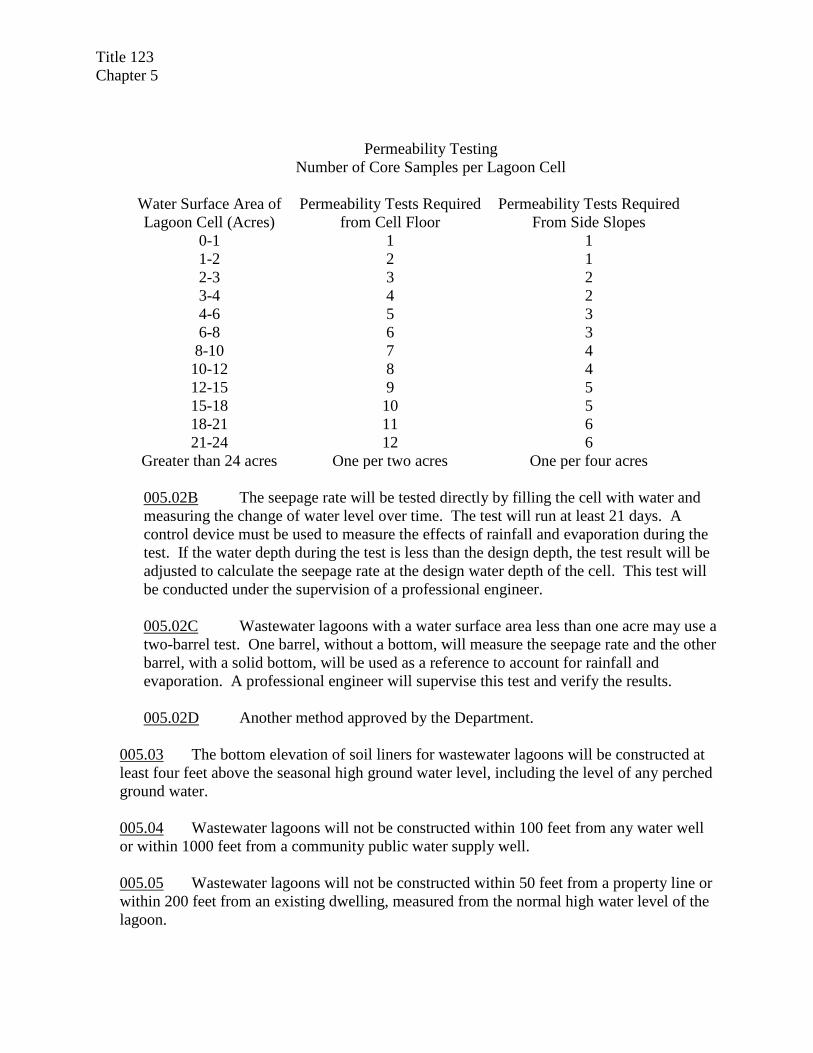
005.02A An independent soils testing laboratory will determine the coefficient of permeability from undisturbed core samples taken from the liner. The seepage velocity will be calculated using Darcy’s Law at the design maximum water depth. Each permeability test will pass the seepage test. Areas that do not pass will be reworked and retested. The minimum number of core samples that will be tested is listed in the following table.
Title 123 Chapter 5
Permeability Testing Number of Core Samples per Lagoon Cell
Water Surface Area of Lagoon Cell (Acres)
Permeability Tests Required from Cell Floor
Permeability Tests Required From Side Slopes
0-1 1 1 1-2 2 1 2-3 3 2 3-4 4 2 4-6 5 3 6-8 6 3 8-10 7 4 10-12 8 4 12-15 9 5 15-18 10 5 18-21 11 6 21-24 12 6
Greater than 24 acres One per two acres One per four acres
005.02B The seepage rate will be tested directly by filling the cell with water and measuring the change of water level over time. The test will run at least 21 days. A control device must be used to measure the effects of rainfall and evaporation during the test. If the water depth during the test is less than the design depth, the test result will be adjusted to calculate the seepage rate at the design water depth of the cell. This test will be conducted under the supervision of a professional engineer. 005.02C Wastewater lagoons with a water surface area less than one acre may use a two-barrel test. One barrel, without a bottom, will measure the seepage rate and the other barrel, with a solid bottom, will be used as a reference to account for rainfall and evaporation. A professional engineer will supervise this test and verify the results.
005.02D Another method approved by the Department.
005.03 The bottom elevation of soil liners for wastewater lagoons will be constructed at least four feet above the seasonal high ground water level, including the level of any perched ground water. 005.04 Wastewater lagoons will not be constructed within 100 feet from any water well or within 1000 feet from a community public water supply well. 005.05 Wastewater lagoons will not be constructed within 50 feet from a property line or within 200 feet from an existing dwelling, measured from the normal high water level of the lagoon.
Title 123 Chapter 5
005.06 Wastewater lagoons will be designed and constructed to prevent storm water runoff from flowing into the cells and to prevent storm water runoff or surface water flow from eroding the earthen dikes.
005.07 The top of wastewater lagoon dikes will be constructed at least one foot above the 100-year flood elevation at the site. 005.08 The top of wastewater lagoon dikes will have a minimum width of eight feet to accommodate maintenance vehicles. 005.09 Wastewater lagoons will be provided with influent flow measurement equipment capable of measuring the total influent flow. Elapsed time meters on lift station pump controls are acceptable to meet this requirement. 005.10 Discharging wastewater lagoons will be equipped with an effluent sampling location and a primary flow-measuring device to measure the discharge flow rate. Primary flow devices include parshall flumes, palmer-boelus flumes, V-notch weirs, rectangular weirs, trapezoidal weirs or similar devices. Level monitoring equipment or flow meters will be included with the primary flow-measuring device for continuous discharge lagoons, but is not required for controlled discharge lagoons. 005.11 All wastewater lagoons will be completely enclosed by a fence, unless exempted by the Department. The fencing will be at least 42 inches high and will include at least one lockable gate, a minimum of 10 feet wide. 005.12 A warning sign will be posted on each side of a wastewater lagoon system. Sides longer than 500 feet will have one sign for every 500 feet or fraction thereof. The signs will be at least 12 inches by 24 inches in size and clearly show the words “No Trespassing, Wastewater Lagoon” or similar language. 005.13 The organic loading rate of facultative lagoon systems will not exceed 30 pounds of five-day biochemical oxygen demand (BOD5) per acre per day for primary cells. The organic loading rate for the entire lagoon system will not exceed 25 pounds of BOD5 per acre per day. 005.14 Facultative lagoons will have a maximum water depth of six feet in primary cells and eight feet in secondary cells. Greater depths may be approved if mechanical aeration is provided. 005.15 Discharging wastewater lagoon systems will be designed with multiple cells that operate in series. Where two or more primary cells are provided, a control structure will be designed to split the flow proportionally or to divert the influent flow to either cell. 005.16 The finished floor elevation of wastewater lagoons will not vary more than three inches from the design elevation or grade.
Title 123 Chapter 5
005.17 After seepage testing is completed, newly constructed wastewater lagoons will be filled with two feet of water to protect the liner from damage and to reduce odors when the lagoons first receive wastewater. Lagoon cells that will not be placed into immediate service will follow the requirements of Chapter 11, 008.04.
005.18 Rapid Infiltration (RI) Cells will be designed according to the following design standards. 005.18A RI cells will have at least 10 feet from the bottom of the cell to the seasonal high ground water level.
005.18B RI cells will be designed to operate in a cycle consisting of a water application period followed by a drying period. The length of the drying period will be adequate to restore aerobic conditions to the soil and will not be shorter than the application period. The application period will include all time that any standing water is visible in the cell. 005.18C RI systems that discharge to ground water will be designed to achieve a total nitrogen concentration of 10 milligrams per liter (mg/l) or less entering ground water. 005.18D Ground water monitoring wells will be required at all rapid infiltration systems.
006 Mechanical Plants
006.01 Flow Measurement
006.01A Plants with an average daily design flow less than 50,000 gallons per day will have either influent or effluent flow measurement. Lift station elapsed time meters will satisfy this requirement. 006.01B Plants with an average daily design flow of 50,000 gallons per day or greater will have continuous flow measurement and totalizing equipment. 006.01C Flow measurement equipment will be sized to function accurately over the full range of flows received at the treatment plant. The flow measurement equipment will be protected from freezing.
006.02 Bar Screens & Comminutors

Title 123 Chapter 5
006.02A Every mechanical plant will have either screening devices or comminutors installed. 006.02B At least two flow channels will be provided for screens or comminutors. Each channel will be designed to handle the peak hourly flow. 006.02C Comminutors will be located after grit removal facilities. If grit removal is not provided, the flow channels upstream of comminutors will have a gravel trap installed to protect the comminutor from damage. 006.02D Where a comminutor is installed, a bypass bar screen will also be provided. Flows exceeding the operating capacity of the comminutor will automatically be diverted to the bar screen channel.
006.03 Grit Removal
006.03A Grit removal facilities, when provided, will be located after screening devices, but prior to comminutors or other treatment units. 006.03B Ventilation will be provided for grit removal facilities that are covered or housed in a building. Fresh air will be continuously forced into the facility at a minimum rate of 12 air changes per hour or intermittently at a minimum rate of 30 air changes per hour. 006.03C Grit removal facilities will be provided with drains to dewater the unit for maintenance and be equipped with a bypass line. 006.03D Grit removal facilities will be provided with means to dry and store grit prior to disposal. Grit removal and grit handling facilities will be protected from freezing.
006.04 Primary Clarifiers
006.04A Plants with an average daily design flow of 100,000 gallons per day or greater will have multiple primary clarifiers, if primary clarifiers are part of the facility. Each clarifier will be capable of independent operation. When a single primary clarifier is provided, a bypass line to the secondary treatment unit will be provided. 006.04B The minimum sidewall depth of primary clarifiers will be 10 feet. 006.04C The horizontal distance from the inlet to outlet will be at least 10 feet, unless the design includes a method to prevent short-circuiting. 006.04D The surface overflow rate will not exceed 1000 gallons per day per square foot at the average daily flow or 3000 gallons per day per square foot at the peak hourly

Title 123 Chapter 5
flow. Returned flows from later treatment units will be included in the flow used to calculate the surface overflow rate.
006.05 Activated Sludge Basins
006.05A The dimensions of each aeration tank will be such that it maintains effective mixing and utilization of air. Vertically mixed tanks will have a liquid depth of not less than 10 feet or greater than 30 feet. Horizontally mixed tanks will have a minimum liquid depth of 5.5 feet. 006.05B All aeration tanks will have a freeboard of not less than 18 inches. Aeration tanks using mechanical surface aerators will have at least three feet of freeboard. 006.05C Inlets and outlets for each aeration basin will be suitably equipped with valves, gates, stop plates, weirs, and other devices to permit controlling the flow to any unit and maintain reasonably constant liquid levels. Where multiple aeration basins are provided, the hydraulic properties of the inlets and outlets will be sized to carry the design peak instantaneous flow with any single aeration tank out of service. 006.05D Channels and pipes that carry solids in suspension will be designed to maintain a self-cleansing velocity at all rates of flow within the design limits. Open channels will be designed to prevent splashing out of the channel. 006.05E The shape of aeration tanks, the location of influent and return sludge pipes, and the aeration equipment will be designed to prevent short-circuiting through the tanks. 006.05F The rate of sludge return will be controlled by means of variable speed motors, drives, valves, or timers to pump sludge at the required rates. If motor driven return sludge pumps are used, a minimum of two pumps is required. The pumps will be sized to meet the required pumping rates with the largest pump out of service. Pumps will have at least a 3-inch suction and discharge opening. No standby unit is required for air lift pumps, provided the design facilitates rapid and easy cleaning. Airlift pumps will be at least 3 inches in diameter. Airlift pumps used to waste or return sludge will be designed so their operation is unaffected by changes of air demand of other treatment units.
006.05G Return sludge piping will be at least four inches in diameter and designed to maintain a velocity of not less than two feet per second when return facilities are operating at normal return rates. Suitable devices will be provided for measuring and controlling the return rate. The flow will be returned near the inlet or head end of the aeration tank, so that it rapidly mixes with the influent. Return sludge piping will be designed to provide the operator easy access for collection of return sludge samples.
Title 123 Chapter 5
006.05H Sludge wasting facilities will be provided for all activated sludge facilities.
Sludge wasting facilities include units such as sludge thickening tanks, sludge digestion facilities, sludge storage tanks, dewatering facilities or any practical combination of these units. A means of measuring, controlling, and sampling of waste activated sludge must be provided.
006.05I Aeration equipment will be capable of maintaining a minimum dissolved oxygen concentration of 2.0 milligrams per liter in the mixed liquor at all times and provide thorough mixing of the mixed liquor. For all activated sludge processes, except extended aeration, the minimum oxygen requirements will be 1.1 pounds of oxygen per pound of the design peak hourly five-day biochemical oxygen demand (BOD5) applied to the aeration tank. For the extended aeration process the minimum oxygen requirement will be 1.5 pounds of oxygen per pound of the design peak hourly BOD5 applied to the aeration tank. Where nitrification is required, the oxygen requirement for oxidizing ammonia must be added to the above requirement for oxidation of five-day biochemical oxygen demand. The minimum nitrogenous oxygen requirement will be 4.6 pounds of oxygen per pound of the design peak hourly total Kjeldahl nitrogen applied to the aeration tank. 006.05J The design of the diffused air system will be based on either standard engineering equations that calculate the transfer efficiency using such factors as tank depth, alpha and beta factors, device transfer efficiencies, wastewater temperature and altitude of the plant or empirically determined air requirements. Designs based on standard engineering equations will include the transfer efficiency in the specifications.
Empirical air requirements for all activated sludge processes, except extended aeration,
will be a minimum of 1500 cubic feet of air (at standard conditions of pressure, temperature, and humidity) per pound of five-day biochemical oxygen demand (BOD5) applied to the aeration tank. For the extended aeration process the air requirements will be 2050 cubic feet of air per pound of BOD5 applied to the aeration tank.
006.05K The specified capacity of blowers or air compressors will take into account the range of ambient air conditions that may occur at the site.
006.05L A minimum of two blowers will be provided for any activated sludge
facility. The capacities of blowers or air compressors will be able to meet the air demand of the system with the largest unit out of service.
006.05M Plants with less than four independent aeration tanks will be designed to
allow removal of the diffusers for service or replacement without dewatering the tank. 006.05N In the absence of specific design information, the oxygen requirements
will be calculated using a transfer rate not to exceed two pounds of oxygen per

Title 123 Chapter 5
horsepower per hour. The design requirements of a mechanical aeration system will maintain a dissolved oxygen concentration of two milligrams per liter in the mixed liquor at all times throughout the tank, maintain solids in suspension, and meet the oxygen demand requirements with the largest unit out of service.
006.06 Trickling Filters
006.06A Trickling filters will be preceded by primary sedimentation to remove scum, grease, and floatable debris or by other suitable treatment facilities. 006.06B The volume of trickling filter media will be based upon pilot testing with the particular wastewater or by using design equations. The volume of media will be calculated on the design maximum day organic loading. The design volume will also include treatment of the organic loading of recycle flows from other treatment units such as, digester supernatant, mechanical dewatering supernatant, or others.
006.06C Media will have a minimum depth of six feet above the underdrains. Rock or slag media will not exceed 10 feet in depth. Manufactured media will not exceed the depth recommended by the manufacturer. 006.06D Rock media will not contain more than five percent by weight of pieces whose longest dimension is three times the least dimension. It will be free of thin, elongated and flat pieces, dust, clay, sand, or fine material and will conform to the following size and grading. Passing 4 ½ inch screen - 100% Retained on 3 inch screen – 95-100% by weight Passing 2 inch screen – 0 – 2% by weight Passing 1 inch screen – 0-1% by weight 006.06E Manufactured media will be resistant to ultraviolet degradation, disintegration, erosion, aging, all common acids and alkalis, organic compounds, and fungus or biological attack. Media will be structurally capable of supporting the weight of a person or a suitable access walkway will be provided for maintenance of the distributor. Manufactured media for carbonaceous treatment will not have a specific area greater than 30 square feet per cubic foot. Manufactured media for second stage ammonia treatment will not have a specific area greater than 45 square feet per cubic foot.
006.06F The piping system, including dosing and distributor equipment, will be designed to provide capacity for the design peak hourly flow including the recirculation rate. The design recirculation ratio (ratio of recirculation flow to design average flow) will be based on the amount of variation in plant flow between design minimum daily flow and design peak hourly flow.
Title 123 Chapter 5
006.06G The piping system will be designed for recirculation as required to achieve the design wetting rate, or design dosing rate, and to achieve the design treatment efficiencies. The design of recirculation facilities will provide for continuity of service, variable recirculation rates, measurement of the recirculation rate, and subject to control by the plant operator. A minimum of two recirculation pumps must be provided. 006.06H The wastewater will be distributed by rotary, fixed nozzle, or other suitable distributor that ensures uniform distribution over the entire surface area. The distribution equipment will be able to apply wastewater at the design hydraulic loading rate (gallons per minute per square foot) or dosing rate (inches per revolution). At design average flow, the deviation from a calculated uniformly distributed volume per square foot of the filter surface will not exceed plus or minus 10 percent at any point. 006.06I There will be a minimum of 12 inches of clearance between the media and the distribution arms. 006.06J A freeboard of four feet or more will be provided for tall manufactured uncovered trickling filters to contain windblown spray.
006.06K Appropriate valves, sluice gates, or other structures will be provided to enable flooding of the filter. Access will be provided around the periphery of the underdrain system to allow flushing of the underdrains. 006.06L The underdrain system will cover the entire floor of the filter. Inlet openings into the underdrains will have an unsubmerged combined area equal to at least 15 percent of the surface area of the filter. The underdrains will have a minimum slope of one percent. Effluent channels will be designed to produce a minimum velocity of two feet per second at design average daily flow rates including recirculated flows. 006.06M The underdrain system and effluent channels will be designed to permit free passage of air. The size of the drains and channels will be designed such that no more than 50 percent of their cross-sectional area will be submerged under design peak flow conditions. Forced ventilation will be provided for covered trickling filters to insure adequate oxygen for process requirements. The design of ventilation equipment will provide for operator control of air-flow in accordance with outdoor seasonal temperatures. 006.06N All distribution devices, underdrains, channels, and pipes will be installed so that they allow for proper maintenance.
006.07 Intermediate and Final Clarifiers
006.07A Facilities with an average daily design flow of 100,000 gallons per day or greater will have multiple final clarifiers. Effective flow splitting devices and control
Title 123 Chapter 5
appurtenances will be provided to permit proper proportioning of flows and solids to each unit, throughout the expected range of flows. 006.07B The minimum distance between inlet and outlet will be 10 feet, unless the design includes a method of preventing short-circuiting. The minimum side water depth will be 12 feet. Walls of settling tanks will extend at least six inches above the surrounding ground surface and will have a minimum of 12 inches of freeboard. 006.07C Surface overflow rates will be calculated based on design average and design peak hourly influent flow conditions. The solids loading rate will be calculated based on the design average daily flow or design maximum day flow plus the design maximum return sludge rate plus the design mixed liquor suspended solids (MLSS). 006.07D Influent pipes and center columns of circular clarifiers will have a maximum velocity of 2.0 feet per second. Inlet structures will be designed to dissipate the inlet velocity, to distribute the flow equally both horizontally and vertically and to prevent short-circuiting. Corner pockets and dead ends will be eliminated and corners fillets or channeling will be used where necessary. Provisions will be made to eliminate or remove floating materials from inlet structures. 006.07E Overflow weirs will be adjustable to correct for differential settlement. Weirs will be located to optimize hydraulic detention time and minimize short-circuiting. The loading rate at design peak hourly flow will not exceed 20,000 gallons per day per lineal foot of weir for plants with a design flow less than one million gallons per day (MGD) or 30,000 gallons per day per lineal foot of weir for plants with a design flow greater than one million gallons per day. Weir troughs will be designed to prevent submergence at design peak hourly flow and maintain a velocity of 1.0 foot per second at one-half the design average flow.
006.07F Provisions for scum collection and removal will be provided for all clarifiers. Scum will be discharged to a sludge treatment unit or scum storage unit that prevents recycling of the scum through the secondary treatment units. Scum will not be discharged to the head of the plant, unless it can be permanently removed from the system in a primary clarifier or similar treatment unit. 006.07G All final and intermediate clarifiers will have a mechanical sludge scraper or collection system. Suction withdrawal will be provided for activated sludge final clarifiers with a diameter greater than 60 feet. Each settling tank will have its own sludge withdrawal lines to insure adequate control of sludge wasting from each tank. 006.07H All settling tanks will be equipped with appropriate equipment such as machinery covers, walkways, handrails, area lighting, and slip resistance surfaces that enhance the safety of the operator. The design will provide for convenient and safe access to routinely checked items such as gear-boxes, scum removal mechanisms, baffles, weirs, inlet areas, and effluent channels.

Title 123 Chapter 5
006.08 Sludge Treatment, Storage, and Disposal
006.08A Facilities for the treatment and storage of sludge will be provided at all mechanical wastewater treatment plants, unless arrangements are made for processing sludge at another treatment facility. Where sludge is hauled off site for treatment and disposal, an all-weather access road to the treatment plant will be provided. 006.08B Treatment plants using suspended growth processes (activated sludge variations) will, at a minimum, be provided with on-site sludge storage facilities to allow for proper sludge wasting and operational control of the treatment process. 006.08.C Sludge withdrawal piping will have a minimum diameter of eight-inches for gravity withdrawal, and six-inches for pump suction and discharge lines. There will be a minimum of four feet of head above the discharge pipe where withdrawal is by gravity. Provisions for draining and flushing discharge lines will be provided for all gravity sludge piping. The minimum slope for gravity piping will be three percent. A minimum positive head of 24 inches will be provided at the suction side of centrifugal pumps. Suction heads for positive displacement pumps will not exceed 10 feet. 006.08D Anaerobic Sludge Digestion
006.08D1 Digester tanks will be covered with either a fixed or floating cover. Covers will be sealed to protect against gas leaks. The top of the tank will have at least two manholes, not less than 30 inches in diameter, in addition to the gas dome. 006.08D2 The tank bottom will slope towards the withdrawal pipe. A minimum bottom slope of 1:12 is required for tanks equipped with a suction mechanism for sludge withdrawal. A minimum slope of 1:4 is required where sludge is to be removed by gravity. 006.08D3 Where mixing equipment is not provided within the digester, multiple sludge inlets, outlets, and other suction or discharge points will be used to achieve mixing and allow for flexibility of operation. One inlet will discharge above the liquid level near the tank center to facilitate the breakup of scum. Raw sludge inlets will be designed to avoid short-circuiting. 006.08D4 An unvalved, vented overflow will be included to prevent damage to the digester in case of accidental overfilling. The overflow will return the sludge to a treatment unit. 006.08D5 Where rational calculations are not submitted to justify the required tank capacity for heated, anaerobic digestion of domestic wastewater sludge, the minimum volume for completely mixed systems will be 1000 cubic feet of active digester
Title 123 Chapter 5
volume for each 80 pounds of volatile solids per day. Where partial mixing is provided, the minimum volume will be 1000 cubic feet of active digester volume for each 40 pounds of volatile solids per day. 006.08D6 In two stage systems, where the secondary digesters are utilized for thickening and storage, the volume of the secondary digesters will not be used to meet the volume requirement for sludge digestion. 006.08D7 The digester gas system will be designed so that gas is under positive pressure during all normal operations, including during sludge removal from the digester. All enclosed building areas where gas leaks could occur will be provided with ventilation systems. 006.08D8 Supernatant piping will not be less than six-inches in diameter.
006.08E Aerobic Digestion 006.08E1 Where aerobic digesters are used, multiple units will be provided where the design average wastewater flow is at least 100,000 gallons per day.
006.08E2 Volatile suspended solids loading will not exceed 300 pounds per 1,000 cubic feet of volume per day in the digestion units.
006.08E3 A minimum of 15 days of solids retention time will be provided for waste activated sludge and 20 days for a combination of primary and waste activated sludge, or for primary sludge alone. In order to qualify as a Process to Significantly Reduce Pathogens (See Title 119 – Rules and Regulations Pertaining to the Issuance of Permits Under the National Pollutant Discharge Elimination System, Chapter 12, 004), aerobic digestion processes will have a minimum mean cell residence time of 40 days at 20° Celsius and 60 days at 15° Celsius. If supernatant separation is performed in the digestion tank, additional volume is required to allow for decanting. This added volume will not be included in the determination of mean cell residence or solids retention time. 006.08E4 Sufficient air will be provided to keep solids in suspension and maintain a dissolved oxygen concentration of 1.0 milligram per liter. The minimum amount of air supply will be 30 cubic feet per minute per 1000 cubic feet of tank volume with the largest blower out of service. The minimum requirement for mechanical aerators will be 1.0 horsepower per 1000 cubic feet of digester volume. 006.08E5 Facilities will be provided for the separation and decanting of supernatant. The supernatant draw off unit will be designed to prevent recycling of scum and

Title 123 Chapter 5
grease back to the wastewater treatment processes. A method for the collection and disposal of scum and grease will be provided. 006.08E6 An unvalved high-level overflow will be provided to return digester overflow back to the head of the plant or to a secondary treatment unit to protect against accidental overfilling.
006.09 Disinfection
006.09A Chlorine Disinfection
006.09A1 The chlorination system and equipment will be sized to produce an effluent meeting applicable bacterial limits at design peak flow conditions. 006.09A2 Where 100 or 150 pound chlorine gas cylinders are used, the cylinders will be stored in an upright position with adequate support brackets and chains at the two-thirds cylinder height for each cylinder. Storage containers for hypo-chlorite solutions will be of sturdy, non-metallic lined construction and will be provided with secure tank tops and pressure relief and overflowing piping. Storage tanks will be vented outside. Tanks will be located where leakage will not cause corrosion or damage to other equipment. A means of secondary containment to control spills and facilitate cleanup will be provided.
006.09A3 Scales for weighing cylinders and containers will be provided at all plants using chlorine gas.
006.09 A4 The disinfectant will be mixed as rapidly as possible. A minimum contact time of 15 minutes at design peak hourly flow or maximum pumping rate will be provided after thorough mixing. The chlorine contact tank will be constructed to reduce short-circuiting.
006.09A5 Piping systems will be as simple as possible and selected and manufactured to be suitable for chlorine service. Piping will be well supported and protected against temperature extremes. The chlorine piping will be color-coded and labeled to distinguish it from other plant piping. Piping and fittings for chlorine and sulfur dioxide will be designed so that interconnection between the two systems cannot occur.

Title 123 Chapter 5
006.09A6 If gas chlorination equipment or chlorine cylinders are to be in a building used for other purposes, a gas-tight room will separate this equipment from other portions of the building. Floor drains from the chlorine room will not be connected to floor drains from other rooms. Doors to this room will open to the outside, and will be equipped with panic hardware. Rooms will be at ground level and should permit easy access to all equipment. Storage areas for one-ton cylinders will be separated from the feed area. A clear glass, gas-tight window will be installed in an exterior door or interior wall of the chlorinator room to permit the units to be viewed without entering the room. 006.09A7 Forced, mechanical ventilation will be installed that provides one complete air exchange per minute when the room is occupied. The entrance to the air exhaust duct from the room will be near the floor. The point of discharge will be located so as not to contaminate the air inlet of another building. Air inlets will be located to provide cross ventilation with air at such a temperature that will not adversely affect the chlorination equipment. The outside air inlet will be at least three feet above grade. The vent hose from the chlorinator will discharge to the outside atmosphere above grade. 006.09A8 Switches for fans and lights will be located outside the room at the entrance. If the fan can be controlled from more than one point, a labeled signal light indicating fan operation should be provided at each entrance. 006.09A9 Respiratory protection equipment, meeting the requirements of National Institute for Occupational Safety and Health (NIOSH) will be available where chlorine gas is handled, and will be stored at a convenient location, but not inside any room where chorine is used or stored.
006.09B Dechlorination
006.09B1 The dechlorination chemical will be introduced at a point in the process where the hydraulic turbulence is adequate to assure complete and thorough mixing. If no point exists, mechanical mixing will be provided. A minimum of 30 seconds for mixing and contact time will be provided at the design peak hourly flow or maximum rate of pumping.
006.09C Ultraviolet (UV) Radiation Disinfection
006.09C1 For facilities with a design average day flow of 100,000 gallons or more, a UV disinfection system will consist of multiple banks of lamp modules in series that are capable of continuously disinfecting the effluent with one bank out of service.

Title 123 Chapter 5
006.09C2 Provisions will be made for easy removal and inspection of the UV lamps without draining the disinfection chamber.
006.09C3 The contact chamber will be designed so that the UV lamps remain submerged at all times during operation and to maintain a near constant water level at all design flow conditions.
007 Truck Wash Wastewater Treatment Facilities
007.01 Livestock Truck Washes
007.01A Livestock truck washes will either connect to a public sanitary sewer system or to a wastewater works designed and constructed according to the following standards. 007.01B Livestock truck washes will include wash pads that capture all wash water from the washing operation and convey it to the wastewater works. Wash pads will be constructed of concrete or another impermeable material. 007.01C One of the following wastewater systems will be used for livestock truck washes.
1) A complete retention facultative lagoon system. 2) A wastewater storage pond and land application system. 3) A solids separation system, wastewater storage pond and land application
system. 4) Another system proposed by the owner and approved by the
Department.007.01D Lagoons and storage ponds used for truck washes will meet the design standards and testing requirements in Chapter 5, 005.
007.01E Wastewater facilities designed to separate solids from the wash water for separate handling and disposal will include a settling pit and a solids storage unit as specified below.
007.01E1 Solids settling pits will be constructed of concrete and will be watertight. Pits will have at least 24-hour detention time and be designed to contain both floatable and settleable solids. The design will include a method to remove solids from the pit. 007.01E2 Solids storage units will be watertight structures designed to dry and store solids removed from solids settling pits. A drain system will return surplus water back to the solids settling pit or to the lagoon. At least 120 days of solids storage will be provided with controls to prevent storm water runoff.

Title 123 Chapter 5
007.01F The hydraulic design of the WWTF will be based on historic flow records from other facilities using similar washing equipment. Where verifiable flow records do not exist, a flow not less than1500 gallons per truck washed will be used for design. 007.01G The solids handling capacity will be based on data from similar facilities or on specific data from the owner’s operation, such as the size of animals, the length of trips, the type of bedding material, and manure production rates. In the absence of specific data, the design will assume ten cubic feet of solids (bedding and manure) generated from each truck washed.
007.01H Livestock truck washes will receive written approval, including site approval, from the Department prior to land applying wastewater or wastewater solids. 007.01I Irrigation piping networks used to apply lagoon water will be equipped with check valves, vacuum relief valves, and low pressure drains, as necessary, to protect ground water wells or other sources or irrigation water from contamination from the back flow of lagoon water. 007.01J Livestock truck wash projects that are submitted for approval must include a written management plan adequate to prevent chemical tank trucks, garbage trucks, septage haulers, or other vehicles that could contain hazardous, toxic, or pathogenic wastes from using the livestock truck wash. Any security devices or structures described in the management plan to regulate usage must be shown on the plans submitted for approval. 007.01K A livestock truck wash that was reviewed and approved by the Department as part of an animal feeding operation (AFO) that has received approval for the livestock waste control facility under Title 130, Livestock Waste Control Regulations, is exempt from the construction permit requirements of this Title.
008 Constructed Wetlands
008.01 Primary treatment will be provided for constructed wetlands. Lagoons will not be used to provide primary treatment for vegetated submerged bed constructed wetlands unless a reliable means to remove algae is provided. 008.02 Multiple constructed wetland cells will be provided if the design flow is 5000 gallons per day or greater. Bypass structures will be included to allow each cell to be isolated. 008.03 Constructed wetland systems will be designed to prevent storm water runoff from entering any part of the wastewater works, unless specifically designed to treat runoff.

Title 123 Chapter 5
008.04 Constructed wetland cells that treat domestic strength wastewater will have seepage rates no greater than one-eighth inch per day. Liners for constructed wetlands cells that treat higher strength wastewater will meet the seepage rate specified by the Department for the specific waste. 008.05 The bottom of the soil liner will be at least four feet above the seasonal high ground water level.
008.06 Effluent structures will be equipped with water level control devices capable of controlling the water depth in the wetland cell anywhere from the maximum design level to the bottom of the cell. 008.07 The gravel media installed in vegetated submerged bed constructed wetlands will be graded gravel, sized not less than three-eighths inch or larger than one-inch in diameter. Except that:
008.07A Up to six inches of washed pea gravel may be laid above the media to aid in plant rooting, and 008.07B One-inch to three-inch cobbles may be installed at the influent and effluent ends to assist in flow distribution and collection.
Enabling Legislation: Neb. Rev. Stat. §81-1504(10) Legal Citation: Title 123, Ch. 5, Nebraska Department of Environment and Energy

NEBRASKA ADMINISTRATIVE CODE
Title 123 - NEBRASKA DEPARTMENT OF ENVIRONMENT AND ENERGY Chapter 6 – APPROVAL OF ALTERNATIVE DESIGNS 001 The design engineer of a wastewater works may request that the director approve an alternative design that does not meet the minimum design standards and specifications in this title. To request approval of an alternative design, a written request will be submitted explaining the reason for proposing an alternative, describing the alternative design and justifying its use. The director may approve the alternative design if:
001.01 Conforming to the design standard is impractical due to unusual site conditions, existing construction, or other unusual factors. 001.02 The alternative design is based on generally accepted engineering principles, 001.03 The alternative design achieves the same objectives as the design standard, and 001.04 The alternative design protects the environment and public health to a comparable degree as the design standard.
002 The director may approve sanitary sewer designs that do not meet the minimum slope requirement stated in Chapter 5, if the full flowing sewer velocity is at least 1.5 feet per second. To request approval, the owner of the collection system will submit a letter to the director stating that they accept the design and are willing and able to provide additional cleaning to maintain the flatter sewer. Enabling Legislation: Neb. Rev. Stat. §81-1504(10) Legal Citation: Title 123, Ch. 6, Nebraska Department of Environment and Energy

NEBRASKA ADMINISTRATIVE CODE
Title 123 - NEBRASKA DEPARTMENT OF ENVIRONMENT AND ENERGY Chapter 7 – SUBMISSION OF ENGINEERING DOCUMENTS 001 To apply for a construction permit, the following items will be submitted to the Department for review:
001.01 For a new or modified wastewater treatment facility:
001.01A A facility plan or engineering report. (See Chapter 7, 006) 001.01B A construction permit application form, provided by the Department (see Appendix A). This form is not required if the same information is provided in other submittals. 001.01C The construction plans and specifications. (See Chapter 8) 001.01D Other information specified by the Department.
001.02 For wastewater collection systems:
001.02A A construction permit application form, provided by the Department (see Appendix A). This form is not required if the same information is provided in other submittals. 001.02B A calculation of the maximum design flow at impact points for the proposed sewer. This flow calculation does not need to be submitted for six-inch or eight-inch sewers where the maximum flow is less than 50% of the capacity of the sewer. 001.02C An engineering report is required for satellite lift stations with design average daily flows above 100,000 gallons per day. 001.02D The following statement, signed by a professional engineer, or an explanation from the professional engineer stating why the statement cannot be signed. This statement may be signed on the construction permit application form.
I have reviewed the available design data, flow records, and compliance history of the receiving WWTF. In my professional judgment, the WWTF has the hydraulic and treatment capacity to receive the additional wastewater from this sewer addition and remain in compliance with applicable Department regulations.
001.02E The construction plans and specifications. (See Chapter 8) 001.02F Other information specified by the Department.

Title 123 Chapter 7
002 Facility Plans, engineering reports, plans, and specifications for wastewater works will be prepared by professional engineers registered to practice in the State of Nebraska and be properly sealed, signed and dated. Facility plans for WWTF will be submitted to the Department for review at least 60 days prior to the initiation of design work. 003 The Department will only approve the final construction documents. Plans and specifications marked ‘preliminary’, ‘for review only’, or containing similar statements will not be approved. 004 A minimum of two sets of plans and specifications are to be submitted to the Department for review and approval. One set of the documents will be kept for the Department’s records. All other copies will be returned to the person who submitted them with the Department’s action indicated on them. At least one set of plans will not have been reduced and will show the drawings at full scale. 005 An operation and maintenance manual (O&M manual) will be prepared for all wastewater treatment facilities and satellite lift stations, unless exempted by the Department. Where a sanitary sewer system contains multiple lift stations, a single operation and maintenance manual may be kept for all lift stations in the system and revised to include information on new facilities as needed. For upgrades to WWTF, an existing O&M manual may be modified to describe the upgraded facility. New or revised O&M manuals will be submitted for the Department’s records within 90 days after the completion of construction. O&M manuals will include the following:
005.01 A description of the facility, with site drawings, flow diagrams, tables of treatment and flow capacities, locations of controls, and other information as applicable. 005.02 Copies of regulatory requirements and permits held by the facility, including NPDES permit, Nebraska Pretreatment Program permit, bypass reporting requirements, local sewer use ordinances, ground water monitoring requirements, and other similar information.
005.03 A listing of record keeping requirements and copies of record keeping forms, including discharge monitoring report forms, non-compliance report forms, daily flow log forms, ground water monitoring forms, equipment maintenance forms, and other similar forms. 005.04 Technical discussions on the operation of each control structure, lift station, and treatment unit, the discharge of wastewater effluent, and the proper disposal of grease, screenings, grit, and sludge will be included. Start-up, unit bypass, and shut-down procedures, normal and emergency operating methods, and the correction of common problems will be explained.

Title 123 Chapter 7
005.05 A description of the electric, gas, water, and telecommunications utilities serving the facility, including utility contact information. 005.06 The manufacturer’s literature and maintenance requirements for all mechanical and electrical equipment. 005.07 A discussion on environmental, health, and safety issues surrounding the facility, with a list of emergency phone numbers.
005.08 A discussion on laboratory tests necessary to operate treatment facilities and a list of the lab records that will be kept. 005.09 A complete maintenance schedule.
006 A facility plan or engineering report will contain the detailed planning information that is necessary to evaluate the engineer’s recommendation. Facility plans will include the following:
006.01 A description of existing facilities, the existing service area and population, the current average and peak wastewater flows, a description of the wastewater characteristics, an infiltration and inflow analysis, a summary of commercial and industrial wastewater contributors, a description of existing treatment units and their condition, a review of historical problems and non-compliance events, and the reasons for considering the proposed project. 006.02 Maps showing the location of the existing WWTF and areas available for expansion are to be included. Floodplains, wetland areas, existing housing, depth to ground water, and the location of wells and water utility structures are to be shown. 006.03 The future service area, design population, design flow, and pollutant loading for the projected design life of treatment facilities.
006.04 A description of regulatory requirements that pertain to the wastewater works, including present and proposed draft NPDES permit limits, best management practices, sludge disposal requirements, and the name of the receiving stream. 006.05 A comparison of alternatives that can meet the present and future regulatory requirements will be included. Alternatives are to be ranked for treatment effectiveness, energy efficiency, land requirements, capital and operational costs, ease and flexibility of operation, reliability, environmental impacts, and owner preferences, as applicable.
007 The plans and specifications for design build projects may be submitted to the Department for review and approval in separate phases only if the Department has reviewed and approved a comprehensive wastewater plan prior to submittal of plans and specifications.

Title 123 Chapter 7 008 Projects receiving funding from the Wastewater Treatment Facilities Construction Loan Fund may need to submit additional information and complete other requirements. Refer to Title 131, Rules and Regulations for the Wastewater Treatment Facilities and Drinking Water Construction Assistance Programs. Enabling Legislation: Neb. Rev. Stat. §81-1504(10), 81-1504(30), 81-1505(8) Legal Citation: Title 123, Ch.7, Nebraska Department of Environment and Energy

NEBRASKA ADMINISTRATIVE CODE
Title 123 - NEBRASKA DEPARTMENT OF ENVIRONMENT AND ENERGY Chapter 8 – CONSTRUCTION PLANS AND SPECIFICATIONS 001 Construction plans will include the following information:
001.01 The name or title of the project. 001.02 A vicinity map of the area around the project, with streets, highways, water bodies, and other landmarks shown, as necessary, to identify the location. 001.03 For sanitary sewer additions, the latitude/longitude location of the receiving manhole or furthest downstream manhole will be provided. For WWTF, the latitude/longitude of the head works or first treatment unit will be provided. 001.04 The scale of the drawings and a north arrow will be shown. The locations of soil borings, benchmarks, property lines, easements, and other datum will be shown. 001.05 The construction plans will include elevation, plan, detail, section, and supplemental drawings that, together with the specifications, completely describe the design of the proposed wastewater works. 001.06 Plans for upgrades to WWTF will show how the proposed project relates to the other treatment units in the existing facility. Projects to add additional lagoon cells to a lagoon system will show the existing and proposed control structures, piping, and discharge structures and identify which cells will be used as primary cells. 001.07 Plans for WWTF will include a hydraulic profile of the facility. Schematic flow diagrams showing the flow direction of wastewater, sludge, potable and non-potable water lines, chemical feed lines, and air supply lines through the treatment units will be provided for mechanical WWTF. 001.08 Plans for WWTF will show the normal high and low water levels of the receiving stream, the 100-year flood elevation, and the seasonal high ground water level. 001.09 Plans for WWTF will show the natural drainage ways around the treatment facility. 001.10 The location of all wells, water treatment plants, water storage reservoirs, and water mains in the construction area will be shown. Where a wastewater lagoon, lift station, or mechanical WWTF is proposed, all wells within 1000 feet will be shown. All wells within 50 feet of a proposed sanitary sewer will be shown. Community public water system wells will be identified as such.

Title 123 Chapter 8
001.11 Plans for lift stations will show the seasonal high ground water level and the 100-year flood elevation at the site. 001.12 Extensions or additions to sanitary sewer systems will show the location of the receiving manhole and identify the receiving WWTF. 001.13 Plans for sanitary sewers will include plan and profile drawings showing the continuous elevation of the ground surface, the station numbers, the pipe inverts at each manhole, and the diameter, length, pipe material (if specified), and slope of each sewer segment.
002 The specifications will include the following information: 002.01 The name or title of the project. 002.02 Specifications will include all information not shown on the drawings needed to describe the quality of construction materials, the operating characteristics of mechanical equipment, the standards of workmanship, the fabrication of the project, and the testing requirements for new construction. 002.03 Where construction on existing wastewater works will occur, the specifications will describe the steps that the contractor will follow to maintain operation of the wastewater works during construction.
003 Standard Specifications and Plate Drawings.
003.01 Municipalities and engineering firms may reference standard specifications and plate drawings for the design of sanitary sewers. Municipalities or engineering firms that intend to use standard specifications and plate drawings will submit copies to the Department for review and receive a notice of approval prior to using them for actual projects. 003.02 Where standard specifications and plate drawings are used, the construction plans or bidding documents will contain a statement that all construction will be in accordance with the standard specifications, as adopted or revised on a certain date. No additional submittal of specifications will normally be required, although special supplements to the standard specifications may be required for specific projects. 003.03 Standard specifications and standard plate drawings will be properly signed and sealed by a professional engineer.
Enabling Legislation: Neb. Rev. Stat. §81-1504(10) Legal Citation: Title 123, Ch. 8, Nebraska Department of Environment and Energy
NEBRASKA ADMINISTRATIVE CODE
Title 123 - NEBRASKA DEPARTMENT OF ENVIRONMENT AND ENERGY Chapter 9– CONSTRUCTION OF WASTEWATER WORKS 001 Construction will be in accordance with the approved plans and specifications. When changes to the approved plans and specifications are desired, the following types of changes will be submitted to the Department for review and approval:
001.01 Changes that affect the hydraulic or treatment capacity of a wastewater works. 001.02 Changes to the location or elevation of a wastewater works. 001.03 Changes that alter or modify a treatment process. 001.04 Changes to the method of discharging wastewater, to the discharge location, or that increase wastewater seepage into the ground. 001.05 Changes to the number of installed appurtenances (for example: manholes, diffusers, valves) from the number originally approved in the plans and specifications. 001.06 Changes to the type of mechanical equipment or to the materials specified. 001.07 Changes to the construction quality acceptance testing requirements for the wastewater works. 001.08 Changes to the pipe material, location, slope, or diameter of a sanitary sewer or wastewater piping system or the construction of additional sewers or pipes. 001.09 Changes that could increase the health or safety risk to utility workers or the public.
002 Projects receiving Wastewater Treatment Facilities Construction Loan Fund (commonly referred to as the State Revolving Fund) financing, under Title 131, Rules and Regulations for the Wastewater Treatment Facilities and Drinking Water Construction Assistance Programs will submit all change orders and addenda to the Department for review and approval. 003 Where changes, as listed in Chapter 9, 001, are made to the approved plans and specifications, a set of as-built or record drawings will be submitted for the Department’s records.
Title 123 Chapter 9 004 Upon completion of construction, a written statement from the design engineer or another professional engineer knowledgeable about the construction, will be submitted to the Department stating that construction has been completed in accordance with the approved plans and specifications. Enabling Legislation: Neb. Rev. Stat. §81-1504(10) Legal Citation: Title 123, Ch. 9, Nebraska Department of Environment and Energy
NEBRASKA ADMINISTRATIVE CODE Title 123 - NEBRASKA DEPARTMENT OF ENVIRONMENT AND ENERGY Chapter 10 – ABANDONMENT OF WASTEWATER WORKS 001 Wastewater works that are permanently removed from service will be abandoned in accordance with the regulations in this chapter. 002 Abandoned sanitary sewers or wastewater piping within an abandoned WWTF will have the pipe ends permanently capped or plugged to prevent small animals, vectors, or water from entering the pipes. 003 Abandoned manholes will have the inlet and outlet piping permanently plugged, have at least the upper three feet of the structure removed, and be filled with compacted soil. 004 The abandonment of wastewater lagoons will be completed in the following manner:
004.01 Abandoned lagoons will have the lagoon site re-graded to restore normal drainage to the area and prevent ponding.
004.02 The lagoons will be drained of water down to the sludge layer. The wastewater disposal method will be submitted to the Department and receive approval prior to disposal. 004.03 For lagoons that have received only domestic wastewater, a sludge layer less than six-inches thick may be buried on-site during re-grading of the lagoon dikes and the surrounding area. The sludge will be incorporated into the soil or receive at least one foot of cover material over the sludge layer. 004.04 Sludge amounts in excess of six inches will be removed from the lagoon site and disposed in accordance with applicable federal and state regulations.
004.05 Control structures will be removed to a least three feet below grade and filled with compacted soil. 004.06 Synthetic lagoon liners or covers will be removed from the site.
005 The abandonment of mechanical WWTF and pumping stations will be completed in the following manner:
005.01 The facility will be emptied of wastewater, grit, sludge, and other wastewater residues. All wastewater and solids will be disposed in accordance with applicable regulations. 005.02 Hazardous chemicals will be removed from the site.

Title 123 Chapter 10
005.03 Pumps, comminutors, blowers, and other mechanical equipment will be removed from the site. 005.04 The structure of manholes, wet wells, and other deep confined basins will be removed to at least three feet below grade and filled with compacted soil.
006 Monitoring wells located at WWTF will be properly abandoned according to NAC Title 178, Regulations Governing Water Well Construction, Pump Installation and Water Well Decommissioning Standards. Enabling Legislation: Neb. Rev. Stat. §81-1505(8) Legal Citation: Title 123, Ch. 10, Nebraska Department of Environment and Energy
NEBRASKA ADMINISTRATIVE CODE
Title 123 - NEBRASKA DEPARTMENT OF ENVIRONMENT AND ENERGY Chapter 11 – OPERATION AND MAINTENANCE OF WASTEWATER WORKS 001 Wastewater treatment facilities will be maintained in proper operating condition in accordance with this chapter and operated in a manner to meet all NPDES permit requirements and not result in a prohibited bypass or an unauthorized discharge. 002 All wastewater works will be operated and maintained by a competent, designated operator. The operator shall perform operational tests required by the Department. Records of all tests will be kept for three years and made available to the Director or his authorized representative. Facilities requiring certified operators will meet the requirements of NAC Title 197, Rules and Regulations for the Certification of Wastewater Treatment Facility Operators in Nebraska. 003 Wastewater collection systems will be kept open and free flowing at all times. Adequate sewer cleaning equipment will be kept available within two hours response time. 004 All mechanical devices, including standby or backup units, that are designed and installed in the original WWTF or lift station will be promptly repaired or replaced when they become inoperable. 005 The owner will maintain an inventory of supplies, chemicals, and spare parts, as necessary to maintain uninterrupted operation of the WWTF. 006 An unobstructed, all weather access road will be maintained to WWTFs, lift stations, and to other wastewater structures that could require emergency maintenance. 007 Grit, screenings, grease, scum and similar materials removed from wastewater will be stored in suitable containers before disposal. 008 The operation and maintenance of wastewater lagoons will be conducted in the following manner:
008.01 Lagoon dikes will be maintained with grass to minimize soil erosion, except for areas protected by rip rap or other stabilization methods. The grassed dikes will be mowed to prevent growth of trees or woody plants. Cattails, reeds and other emergent vegetation will be removed from the lagoons promptly as they appear. 008.02 At least two feet of water will be maintained at all times in active wastewater lagoons unless the lagoon has a synthetic liner with an adequate ballast system to prevent uplift from the wind.
Title 123 Chapter 11
008.03 A fence will be maintained around lagoon systems to keep unauthorized persons, pets, and domestic livestock from entering the lagoon. Warning signs will be maintained in legible condition. Gates and locks will be maintained in operable condition. 008.04 If a new lagoon cell is not immediately needed, or if wastewater flow to a lagoon cell is interrupted for a period greater than a year, lagoon cells may be allowed to dry out. These lagoon cells shall be mowed, as necessary, to prevent the growth of woody plants. When inactive lagoon cells are placed into service, the liner’s permeability rate will be tested, and if necessary, restored to meet the seepage rate established by the Department. Synthetic liners that are being placed back into service will be restored to a watertight condition. 008.05 Damage to lagoon dikes and liners caused by muskrats or other rodents, erosion, tree roots, animal hooves, or any other source will be promptly repaired.
008.06 The liners of wastewater lagoons will be maintained so that wastewater seepage does not exceed the rate approved by the Department in the construction plans and specifications. Where no record of approved plans and specifications exist, the lagoon liner will be maintained to meet the seepage rate prescribed by the Department for the specific wastewater being treated. The owner will perform seepage testing when requested by the Department. 008.07 Wastewater lagoons will be operated so that the water level is not maintained in the area designed for freeboard.
009 Rapid infiltration cells will operate in a two-phase cycle of wastewater application followed by a drying period that is sufficient to restore aerobic conditions to the soil. The application period will not exceed seven days unless written permission is obtained from the Department. 010 Dead animal carcasses will not be placed in any wastewater works. Enabling Legislation: Neb. Rev. Stat. §81-1504(12), 81-1505(8) Legal Citation: Title 123, Ch. 11, Nebraska Department of Environment and Energy