800xA for AC 100 - ABB Group · Power and productivity for a better world™ 800xA for AC 100...
92
Power and productivity for a better world™ 800xA for AC 100 Configuration and Operation System Version 6.0
Transcript of 800xA for AC 100 - ABB Group · Power and productivity for a better world™ 800xA for AC 100...

Power and productivity
for a better world™
800xA for AC 100 Configuration and Operation
System Version 6.0

800xA for AC 100
Configuration and Operation
System Version 6.0

NOTICEThis document contains information about one or more ABB products and may include a description of or a reference to one or more standards that may be generally relevant to the ABB products. The presence of any such description of a standard or reference to a standard is not a representation that all of the ABB products referenced in this document support all of the features of the described or ref-erenced standard. In order to determine the specific features supported by a particular ABB product, the reader should consult the product specifications for the particular ABB product.
ABB may have one or more patents or pending patent applications protecting the intellectual property in the ABB products described in this document.
The information in this document is subject to change without notice and should not be construed as a commitment by ABB. ABB assumes no responsibility for any errors that may appear in this document.
Products described or referenced in this document are designed to be connected, and to communicate information and data via a secure network. It is the sole responsibility of the system/product owner to provide and continuously ensure a secure connection between the product and the system network and/or any other networks that may be connected.
The system/product owners must establish and maintain appropriate measures, including, but not lim-ited to, the installation of firewalls, application of authentication measures, encryption of data, installa-tion of antivirus programs, and so on, to protect the system, its products and networks, against security breaches, unauthorized access, interference, intrusion, leakage, and/or theft of data or information.
ABB verifies the function of released products and updates. However system/product owners are ulti-mately responsible to ensure that any system update (including but not limited to code changes, con-figuration file changes, third-party software updates or patches, hardware change out, and so on) is compatible with the security measures implemented. The system/product owners must verify that the system and associated products function as expected in the environment they are deployed.
In no event shall ABB be liable for direct, indirect, special, incidental or consequential damages of any nature or kind arising from the use of this document, nor shall ABB be liable for incidental or conse-quential damages arising from use of any software or hardware described in this document.
This document and parts thereof must not be reproduced or copied without written permission from ABB, and the contents thereof must not be imparted to a third party nor used for any unauthorized pur-pose.
The software or hardware described in this document is furnished under a license and may be used, copied, or disclosed only in accordance with the terms of such license. This product meets the require-ments specified in EMC Directive 2004/108/EC and in Low Voltage Directive 2006/95/EC.
TRADEMARKSAll rights to copyrights, registered trademarks, and trademarks reside with their respective owners.
Copyright © 2003-2015 by ABB.All rights reserved.
Release: October 2015Document number: 3BDS013989-600 A

3BDS013989-600 A 5
Table of Contents
About This User ManualGeneral ..............................................................................................................................9
800xA for AC 100 and AC 100 OPC Server........................................................10
Intended User .......................................................................................................11
Before You Start ...................................................................................................11
Software Components used..................................................................................11
User Manual Conventions ...............................................................................................12
Feature Pack .........................................................................................................12
Warning, Caution, Information, and Tip Icons ....................................................12
Terminology.....................................................................................................................13
Released User Manuals and Release Notes.....................................................................18
Section 1 - ConfigurationOverview..........................................................................................................................21
Functions of the Product ......................................................................................21
Workflow of the Product ......................................................................................22
Data Flow .............................................................................................................23
Configuration workflow and tools .......................................................................27
Libraries and Object Types ..................................................................................30
Supported Aspect Object Types ...........................................................................32
The Control Structure...........................................................................................35
Acknowledge Behavior and Configuration ..........................................................37
About the Bus Configuration Database................................................................38
National Language Support..................................................................................38
Detailed configuration workflow description ..................................................................41
Introduction ..........................................................................................................41

Table of Contents
6 3BDS013989-600 A
Step1: Function Chart Builder Application Configuration.................................. 41
Step2: System 800xA Configuration ................................................................... 41
Step3: Upload static information ......................................................................... 46
Verifying the integration of the uploaded objects ................................................ 49
Configuration of DB Elements........................................................................................ 51
Introduction.......................................................................................................... 51
Extended DB Elements versus DAT-based objects.............................................. 54
Objects requiring no extra DB Element configuration ........................................ 56
DB Element Configuration with Extended DB Elements.................................... 59
DB Element Configuration with Dat-based Elements ......................................... 61
Building a Control Structure for Test and Demo Purposes............................................. 65
Section 2 - OperationOperating the Plant.......................................................................................................... 67
Viewing Process Values ....................................................................................... 67
Viewing Events and Alarms from the Process..................................................... 67
Giving Commands ............................................................................................... 68
Faceplates ............................................................................................................ 68
Object Displays.................................................................................................... 72
Trend Displays ..................................................................................................... 73
Graphical Elements.............................................................................................. 73
Alarm and Event List Displays ............................................................................ 74
Viewing the Control System Status................................................................................. 74
System Status Information from AC 100 Control Systems ................................. 75
System Status - AF100 Network.......................................................................... 79
System Status - Station ........................................................................................ 79
System Status - OPC Objects............................................................................... 81
System Events from AC 100 Control Systems .................................................... 82
Viewing Properties by the Control Connection Aspect................................................... 83
The CCA Property view....................................................................................... 84
Preventive Maintenance .................................................................................................. 85
Backup/Restore Procedures ............................................................................................ 85

Table of Contents
3BDS013989-600 A 7
3BDS013989-600 A 7
Revision History
Index

Table of Contents
8 3BDS013989-600 A

3BDS013989-600 A 9
About This User Manual
General
Any security measures described in this User Manual, for example, for user access, password security, network security, firewalls, virus protection, etc., rep-resent possible steps that a user of an 800xA System may want to consider based on a risk assessment for a particular application and installation. This risk assess-ment, as well as the proper implementation, configuration, installation, opera-tion, administration, and maintenance of all relevant security related equipment, software, and procedures, are the responsibility of the user of the 800xA System.
800xA for AC 100 in principle also supports controllers of type Advant Controller 80. Yet this book does not describe the special configuration tasks required by this controller type. Also there have been no 800xA for AC 100 Product tests performed with this type of Advant controller.
This user manual describes the configuration tasks required for viewing and accessing Advant Controller 100 Series objects in System 800xA and gives some hints about operation and maintenance.
Advant Controller 100 Series controller consists of Advant Controller 70, Advant Controller 110 and Advant Controller 160.
There are a number of User’s guides dealing with Advant Controller 100 Series, Control Builder A, 800xA for AC 100 Products and System 800xA, see Released User Manuals and Release Notes on page 18 for a complete list of references.
The most important manual describing configuration of DB Elements in Function Chart Builder is the Function Chart Builder Users Manual, more information about design and usage of Advant Fieldbus 100 and AC 100 OPC Server you will find in the AC 100 OPC Server Configuration and Operation manual.

800xA for AC 100 and AC 100 OPC Server About This User Manual
10 3BDS013989-600 A
800xA for AC 100 and AC 100 OPC Server
800xA for AC 100 delivers predefined Aspect Object Types for System 800xA. AC 100 OPC Server is utilized as interface to the Advant Controller 100 Series controllers via Advant Fieldbus 100. The delivered Aspect Object Types not only define the presentation of Objects from Advant Controller 100 Series but also the ’methods’ how AC 100 OPC Server is used.
There are three Configuration and Operation manuals available for 800xA for AC 100
• 800xA for AC 100 Configuration and Operation (this book)
• 800xA for AC 100/Advant® OCS, AC 100 OPC Server Configuration and Operation (3BDS013988*)
• 800xA for AC 100 Aspect Object Types (3BDS013986*)
800xA for AC 100 Configuration and Operation (this book) describes Configuration and Operation using the predefined methods of the delivered Aspect Object Types. Normally these methods support all required operation tasks like display, commands or event and alarm handling. If for some reasons special methods are required, for example sending commands cyclically via Datasets, this application is not described within this book; instead the AC 100 OPC Server Configuration and Operation book and other manuals describing the general application of 800xA Aspect Object Types have to be used. 800xA for AC 100 Aspect Object types gives detailed information about Graphical Elements within 800xA for AC 100.
When using the predefined methods described in this book it’s not necessary to refer the 800xA for AC 10/Advant® OCS, AC 100 OPC Server Configuration and Operation (3BDS013988*) book except for items like
• Redundant OPC Servers
• Maintenance and diagnosis
• Setup the handling for process events: severity, event texts etc.
• Details of OPC Items visible as properties of Control Connection Aspects in the System 800xA
Using other than the predefined methods is not supported by the automatic upload function and may conflict with the results of an automatic upload.

About This User Manual Intended User
3BDS013989-600 A 11
• Background information, for example about communication or hints and summaries of how to configure the AC 100 Controllers
Intended User
The information in this book is intended for the Engineer that configures the control system functionality, including writing the control programs and defining the displays and gives in Section 2, Operation some hints and recommendations in case of problems during commissioning, operation and maintenance.
You should have a good understanding about Advant Controller 100 Series and about the functionality of the System 800xA products. You should already know how to use and maintain the hardware platform (PC) and the operating system (Microsoft Windows).
Before You Start
Ensure that the following prerequisites are fulfilled:
• All necessary software products are installed.
• AC 100 OPC Server is configured and running.
You must be logged in as an Engineer or Administrator to be able to perform the engineering work described in this book.
Software Components used
• System 800xAthe Human System Interface and Aspect Object Platform in ABB’s Industrial IT System.
• Control Builder Athe controller configuration tool consisting of:
– Application Builderfor administration and navigation within the configuration data
– Function Chart Builderfor configuration and on-line access of Advant Controllers
– Bus Configuration Builderfor Advant Fieldbus 100 wide checks and overviews

User Manual Conventions About This User Manual
12 3BDS013989-600 A
• 800xA for AC 100 Connectivitythe controller connection interfaces consisting of:
– 800xA for AC 100for automatic configuration of System 800xA from OPC Server data
– AC 100 OPC Server for System 800xAfor OPC access to Advant Controller 100 Series via Advant Fieldbus 100
User Manual ConventionsMicrosoft Windows conventions are normally used for the standard presentation of material when entering text, key sequences, prompts, messages, menu items, screen elements, etc.
Feature Pack
The Feature Pack content (including text, tables, and figures) included in this User Manual is distinguished from the existing content using the following two separators:
Feature Pack Functionality ______________________________________________________________________
<Feature Pack Content>
___________________________________________________________________________________________
Feature Pack functionality included in an existing table is indicated using a table footnote (*) :*Feature Pack Functionality
Feature Pack functionality in an existing figure is indicated using callouts.
Unless noted, all other information in this User Manual applies to 800xA Systems with or without a Feature Pack installed.
Warning, Caution, Information, and Tip Icons
This User Manual includes Warning, Caution, and Information where appropriate to point out safety related or other important information. It also includes Tip to point
About This User Manual Terminology
3BDS013989-600 A 13
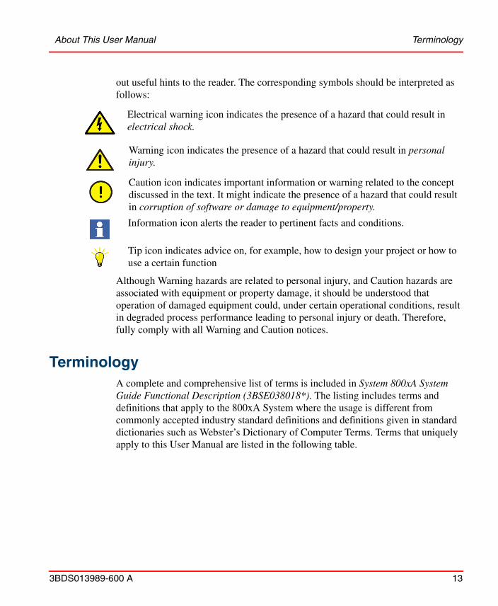
out useful hints to the reader. The corresponding symbols should be interpreted as follows:
Although Warning hazards are related to personal injury, and Caution hazards are associated with equipment or property damage, it should be understood that operation of damaged equipment could, under certain operational conditions, result in degraded process performance leading to personal injury or death. Therefore, fully comply with all Warning and Caution notices.
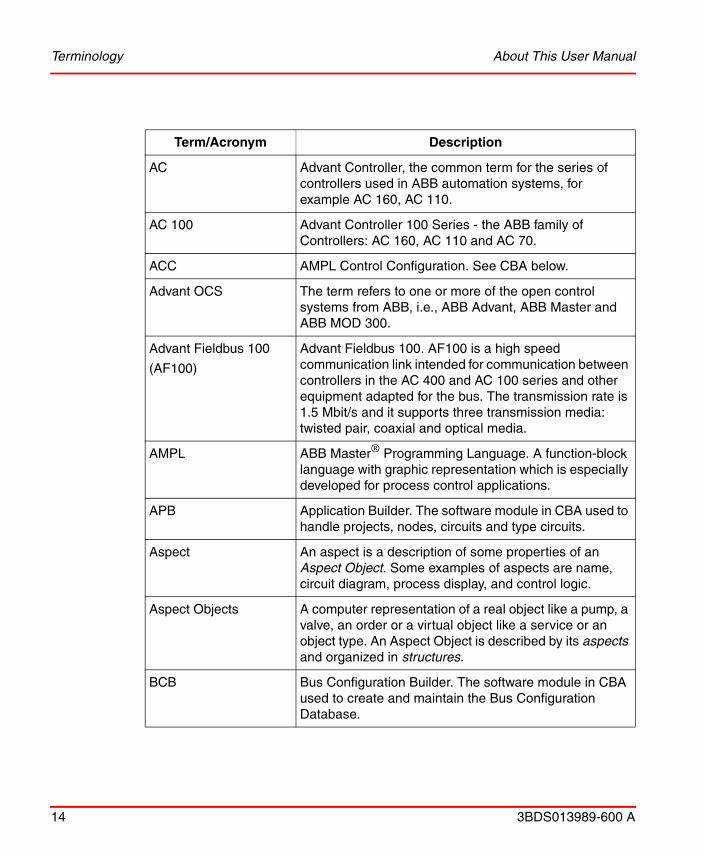
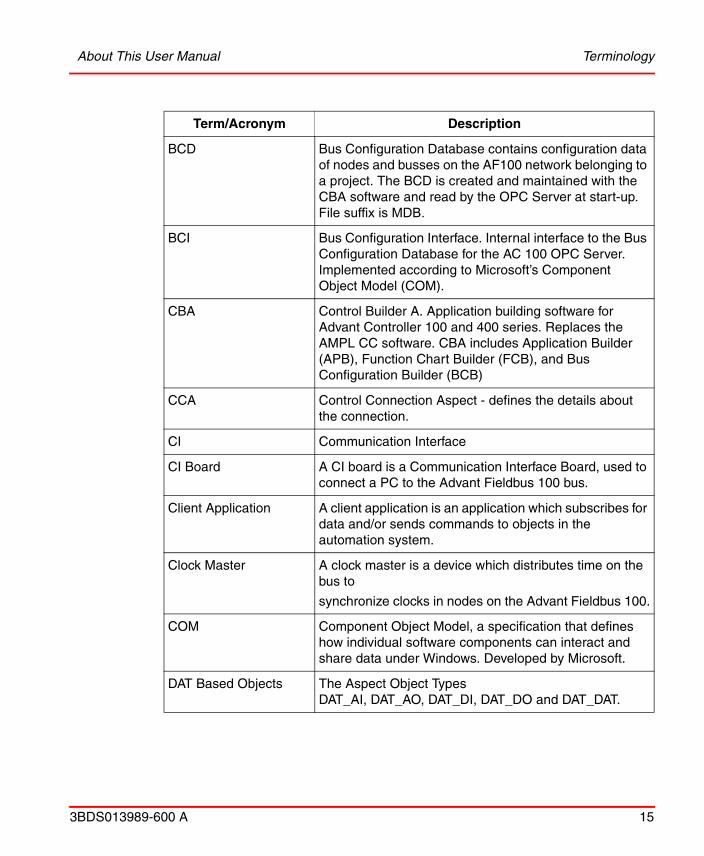
TerminologyA complete and comprehensive list of terms is included in System 800xA System Guide Functional Description (3BSE038018*). The listing includes terms and definitions that apply to the 800xA System where the usage is different from commonly accepted industry standard definitions and definitions given in standard dictionaries such as Webster’s Dictionary of Computer Terms. Terms that uniquely apply to this User Manual are listed in the following table.
Electrical warning icon indicates the presence of a hazard that could result in electrical shock.
Warning icon indicates the presence of a hazard that could result in personal injury.
Caution icon indicates important information or warning related to the concept discussed in the text. It might indicate the presence of a hazard that could result in corruption of software or damage to equipment/property.
Information icon alerts the reader to pertinent facts and conditions.
Tip icon indicates advice on, for example, how to design your project or how to use a certain function
Terminology About This User Manual
14 3BDS013989-600 A
Term/Acronym Description
AC Advant Controller, the common term for the series of controllers used in ABB automation systems, for example AC 160, AC 110.
AC 100 Advant Controller 100 Series - the ABB family of Controllers: AC 160, AC 110 and AC 70.
ACC AMPL Control Configuration. See CBA below.
Advant OCS The term refers to one or more of the open control systems from ABB, i.e., ABB Advant, ABB Master and ABB MOD 300.
Advant Fieldbus 100
(AF100)
Advant Fieldbus 100. AF100 is a high speed communication link intended for communication between controllers in the AC 400 and AC 100 series and other equipment adapted for the bus. The transmission rate is 1.5 Mbit/s and it supports three transmission media: twisted pair, coaxial and optical media.
AMPL ABB Master® Programming Language. A function-block language with graphic representation which is especially developed for process control applications.
APB Application Builder. The software module in CBA used to handle projects, nodes, circuits and type circuits.
Aspect An aspect is a description of some properties of an Aspect Object. Some examples of aspects are name, circuit diagram, process display, and control logic.
Aspect Objects A computer representation of a real object like a pump, a valve, an order or a virtual object like a service or an object type. An Aspect Object is described by its aspects and organized in structures.
BCB Bus Configuration Builder. The software module in CBA used to create and maintain the Bus Configuration Database.
About This User Manual Terminology
3BDS013989-600 A 15
BCD Bus Configuration Database contains configuration data of nodes and busses on the AF100 network belonging to a project. The BCD is created and maintained with the CBA software and read by the OPC Server at start-up. File suffix is MDB.
BCI Bus Configuration Interface. Internal interface to the Bus Configuration Database for the AC 100 OPC Server. Implemented according to Microsoft’s Component Object Model (COM).
CBA Control Builder A. Application building software for Advant Controller 100 and 400 series. Replaces the AMPL CC software. CBA includes Application Builder (APB), Function Chart Builder (FCB), and Bus Configuration Builder (BCB)
CCA Control Connection Aspect - defines the details about the connection.
CI Communication Interface
CI Board A CI board is a Communication Interface Board, used to connect a PC to the Advant Fieldbus 100 bus.
Client Application A client application is an application which subscribes for data and/or sends commands to objects in the automation system.
Clock Master A clock master is a device which distributes time on the bus to
synchronize clocks in nodes on the Advant Fieldbus 100.
COM Component Object Model, a specification that defines how individual software components can interact and share data under Windows. Developed by Microsoft.
DAT Based Objects The Aspect Object TypesDAT_AI, DAT_AO, DAT_DI, DAT_DO and DAT_DAT.
Term/Acronym Description

Terminology About This User Manual
16 3BDS013989-600 A
DB element DB element is an abbreviation for a data base element, which is part of a process control application. DB elements represent e.g. hardware boards (PM645...) or signals (AIS,DSP...).
DCOM Distributed COM. Extends COM to networks.
DSP DataSet Peripheral, a block of data to be transmitted on Advant Fieldbus 100. In the controller the DataSet Peripheral is represented with a database element.
ESD Electrostatic Discharge.
EVS Event Sets, the object type for transmitting time tagged events on the Advant Fieldbus 100 network.
Extended DB Elements These object types offer complete support for the different object attributes: AIS, AOS, DIS, DOS.
FCB Function Chart Builder, the graphic configuration and programming tool in CBA.
Function Chart A function chart is a diagram for the representation of process control programs. It contains graphical symbols (rectangles) for PC elements and lines for connections between element terminals.
HMI
HSI
Human Machine Interface.
Human System Interface.
LED Light Emitting Diode. LEDs are often used as indicators on control panels.
MMI Man Machine Interface.
Object (Process) Object (Process) is a physical or calculated process object, or a functional unit or type circuit containing all related inputs and outputs. An example of a process object is an analog input including value, limits, status, etc. There are two kinds of objects, Extended DB Elements and DAT based objects
Term/Acronym Description

About This User Manual Terminology
3BDS013989-600 A 17
OPC An application programming interface from the OPC Foundation. The application of the OPC standard interface makes possible inter operability between automation/control applications, field systems/devices and business/office applications.
OS Operator Station, a station with operator interactive functionality.
PC An abbreviation for both personal computer and process controller.
PC element PC element is an abbreviation for process control element, which is part of a process control program. PC elements are represented by rectangles in a function chart and by corresponding callnames in a tree diagram
PCI Personal Computer Interface bus. Standard PC bus.
PC program PC program is an abbreviation for process control program.
PCPGM Program header, a PC element.
Property A data field on an aspect of an Aspect Object that can be accessed through OPC.
System 800xA A collection of software that forms the basis for an IndustrialIT System, and provides the development and execution environment for IndustrialIT Compliant applications. Included is the functionality for efficient control and supervision of an automated process; key functions are presentation of process graphics, process dialogs and presentation of alarms and trends.
SDP Service Data Protocol used to send messages on the Advant Fieldbus 100 network.
XDB Extended DB Elements (AIS, AOS, DIS, DOS, MB, MBS, MI, MIL, MR)
Term/Acronym Description
Released User Manuals and Release Notes About This User Manual
18 3BDS013989-600 A
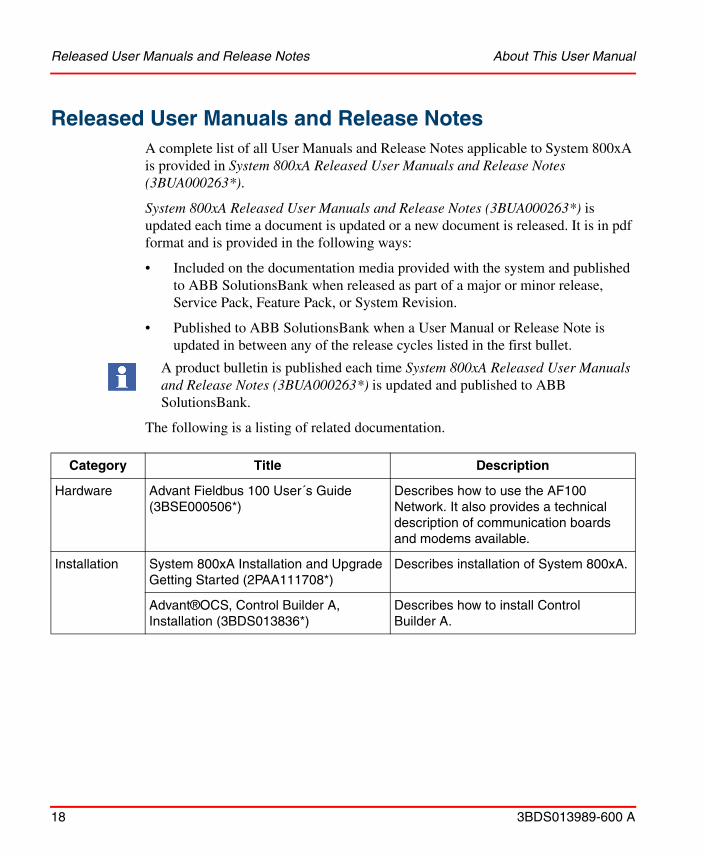
Released User Manuals and Release NotesA complete list of all User Manuals and Release Notes applicable to System 800xA is provided in System 800xA Released User Manuals and Release Notes (3BUA000263*).
System 800xA Released User Manuals and Release Notes (3BUA000263*) is updated each time a document is updated or a new document is released. It is in pdf format and is provided in the following ways:
• Included on the documentation media provided with the system and published to ABB SolutionsBank when released as part of a major or minor release, Service Pack, Feature Pack, or System Revision.
• Published to ABB SolutionsBank when a User Manual or Release Note is updated in between any of the release cycles listed in the first bullet.
A product bulletin is published each time System 800xA Released User Manuals and Release Notes (3BUA000263*) is updated and published to ABB SolutionsBank.
The following is a listing of related documentation.
Category Title Description
Hardware Advant Fieldbus 100 User´s Guide (3BSE000506*)
Describes how to use the AF100 Network. It also provides a technical description of communication boards and modems available.
Installation System 800xA Installation and Upgrade Getting Started (2PAA111708*)
Describes installation of System 800xA.
Advant®OCS, Control Builder A, Installation (3BDS013836*)
Describes how to install Control Builder A.

About This User Manual Released User Manuals and Release Notes
3BDS013989-600 A 19
Software 800xA for AC 100/Advant® OCS, AC 100 OPC Server, Configuration and Operation (3BDS013988*)
Describes how you can configure and use AC 100 OPC Server.
800xA for AC 100, Configuration and Operation (3BDS013989*)
Describes how you can configure and use 800xA for AC 100 (this book).
800xA for AC 100, Aspect Object Types, Reference Manual (3BDS013986*)
Describes how you can configure and use 800xA for AC 100.
System 800xA, Configuration (3BDS011222*)
Describes configuration of System 800xA.
System 800xA, Operations (3BSE036904*)
Describes operation of System 800xA.
System 800xA, Engineering Process Graphics (3BSE049230*)
Describes the configuration of System 800xA process graphics.
Category Title Description
Released User Manuals and Release Notes About This User Manual
20 3BDS013989-600 A
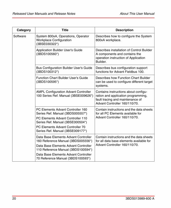
Software System 800xA, Operations, Operator Workplace Configuration (3BSE030322*)
Describes how to configure the System 800xA workplace.
Application Builder User’s Guide (3BDS100560*)
Describes installation of Control Builder A components and contains the operation instruction of Application Builder.
Bus Configuration Builder User’s Guide (3BDS100312*)
Describes bus configuration support functions for Advant Fieldbus 100.
Function Chart Builder User’s Guide (3BDS100595*)
Describes how Function Chart Builder can be used to configure different target systems.
AMPL Configuration Advant Controller 100 Series Ref. Manual (3BSE009626*)
Contains instructions about configu-ration and application programming, fault tracing and maintenance ofAdvant Controller 160/110/70.
PC Elements Advant Controller 160 Series Ref. Manual (3BDS005557*)
PC Elements Advant Controller 110 Series Ref. Manual (3BSE000504*)
PC Elements Advant Controller 70 Series Ref. Manual (3BSE009177*)
Contain instructions and the data sheets for all PC Elements available for Advant Controller 160/110/70.
Data Base Elements Advant Controller 160 Reference Manual (3BDS005556*)
Data Base Elements Advant Controller 110 Reference Manual (3BDS100594*)
Data Base Elements Advant Controller 70 Reference Manual (3BDS100593*)
Contain instructions and the data sheets for all data base elements available for Advant Controller 160/110/70.
Category Title Description

Section 1 Configuration Overview
3BDS013989-600 A 21
Section 1 Configuration
Overview
Functions of the Product800xA for AC 100 enables to view and operate AC 100 Series Controllers in System 800xA in a standardized way and with automatic object configuration based on the control application.
The product 800xA for AC 100 delivers the AC 100 Aspect Object Types. One of these object types, the AC 100 AF100 Network object type includes the automatic Upload function as an aspect.
The product AC 100 OPC Server is the interface to the AC 100 controllers connected via Advant Fieldbus 100. Data for automatic upload as well as all living data - actual values, commands, events and alarms - are processed by the AC 100 OPC Server.
The main functions of the AC 100 Aspect Objects, delivered with 800xA for AC 100, are:
• View current status (process value(s), limits, errors) of the object
• Set new value(s) for the object
• Give Alarm and Event notification about status changes of the object
• Give static information about the object
• Show relations between objects
Figure 1 shows the smallest possible configuration of System 800xA with integrated Aspect and Connectivity Server and the controller configuration tool Control Builder A installed.

Workflow of the Product Section 1 Configuration
22 3BDS013989-600 A
Extensions are possible in direction of:
• More AC 100 nodes, multiple and/or redundant (AC70/80/110/160)
• Separated Connectivity Servers and Aspect servers
• More OPC Server nodes (PCs), multiple and/or redundant
• More System 800xA workplaces (PCs)
Workflow of the ProductDuring Operation the Aspect Object instances of the 800xA for AC 100 Aspect Object Types in the Control Structure provide a standardized access to AC 100
Figure 1. Smallest configuration AC 100 Control System with System 800xA
System 800xA
800xA for AC 100
Section 1 Configuration Data Flow
3BDS013989-600 A 23
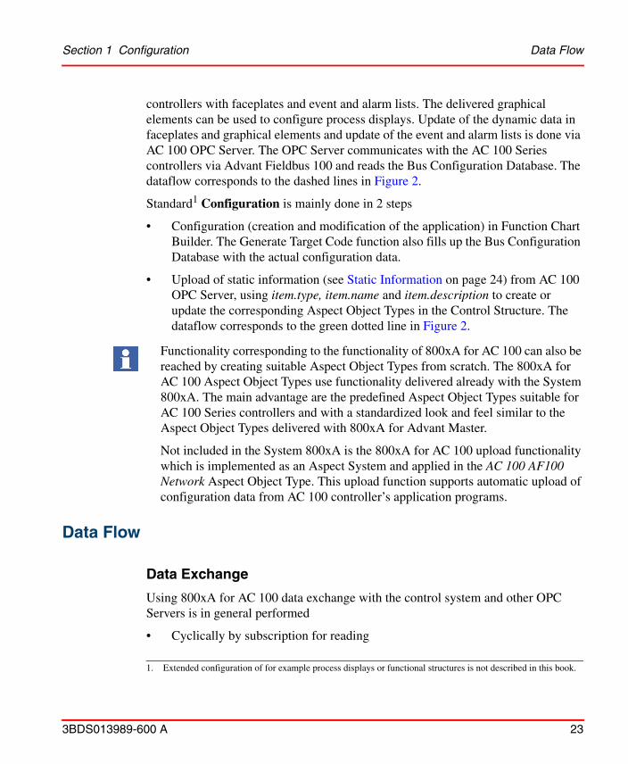
controllers with faceplates and event and alarm lists. The delivered graphical elements can be used to configure process displays. Update of the dynamic data in faceplates and graphical elements and update of the event and alarm lists is done via AC 100 OPC Server. The OPC Server communicates with the AC 100 Series controllers via Advant Fieldbus 100 and reads the Bus Configuration Database. The dataflow corresponds to the dashed lines in Figure 2.
Standard1 Configuration is mainly done in 2 steps
• Configuration (creation and modification of the application) in Function Chart Builder. The Generate Target Code function also fills up the Bus Configuration Database with the actual configuration data.
• Upload of static information (see Static Information on page 24) from AC 100 OPC Server, using item.type, item.name and item.description to create or update the corresponding Aspect Object Types in the Control Structure. The dataflow corresponds to the green dotted line in Figure 2.
Functionality corresponding to the functionality of 800xA for AC 100 can also be reached by creating suitable Aspect Object Types from scratch. The 800xA for AC 100 Aspect Object Types use functionality delivered already with the System 800xA. The main advantage are the predefined Aspect Object Types suitable for AC 100 Series controllers and with a standardized look and feel similar to the Aspect Object Types delivered with 800xA for Advant Master.
Not included in the System 800xA is the 800xA for AC 100 upload functionality which is implemented as an Aspect System and applied in the AC 100 AF100 Network Aspect Object Type. This upload function supports automatic upload of configuration data from AC 100 controller’s application programs.
Data Flow
Data Exchange
Using 800xA for AC 100 data exchange with the control system and other OPC Servers is in general performed
• Cyclically by subscription for reading
1. Extended configuration of for example process displays or functional structures is not described in this book.
Data Flow Section 1 Configuration
24 3BDS013989-600 A
• On demand for writing (commands)
Dynamic Data
The dynamic data processed by AC 100 OPC Server consists of
• Status of hardware modules
• Actual values and status of DB Elements
• Events distributed by AC 100 controllers
• Acknowledge flags distributed by other OPC Servers
Static Information
The static information delivered by AC 100 OPC Server stems from the AC 100 applications created and maintained by Function Chart Builder and from the OPC Server specifications in Bus Configuration Builder.
The Uploader
One of the aspects of the AC 100 AF100 Network object type is called Uploader. The Uploader calls the AC 100 OPC Server to deliver a list of all available OPC items (name, type and description) and their relations. These OPC items represent the stations on the connected AF 100, AC 100 controllers and other OPC Servers,
Use of the terms dynamic and static differs from the view of 800xA for AC 100 (800xA Operator Workplace), AC 100 OPC Server and AC 100 Control System.
In 800xA for AC 100 all data coming from AC 100 OPC Server items are dynamic data. The exception are item.name, item.type and item.description; this data is already used during upload of the configuration data for creation and update of the corresponding Aspect Objects in the Control Structure.
AC 100 OPC Server only delivers dynamic data (= OPC items).
The AC 100 Control System (AC 100 Series controllers and Control Builder A) delivers dynamic data from the controllers and static data from Function Chart Builder and Bus Configuration Builder via Bus Configuration Database BCD to AC 100 OPC Server.

Section 1 Configuration Data Flow
3BDS013989-600 A 25
and their relevant objects and attributes. From this list the corresponding Aspect Objects are created/updated in the Control Structure of the System 800xA.
Subscription
Dynamic data and most of the static data from the controllers and from the Bus Configuration Database can be updated by the Subscribe for live data function in the Control Connection aspect of all object instances which contain such data.
Commands
Graphic Elements and Faceplates allow to send new values (commands) to the different controllers.
Alarms and Events
The procedure to configure and start the Alarm and Event Server in System 800xA is described in Detailed configuration workflow description on page 41.
While Events are reported only, the Alarms in addition have to be acknowledged by the Operator. The acknowledgement is distributed to possible other AC 100 OPC Servers to keep them up to date.
Alarms and Events can be
• generated on AC 100 controllers and sent to System 800xA
• generated on System 800xA by supervision of values
Figure 2 show the sinks and sources of data for upload, subscription and for commands.
If a graphical or faceplate element is selected on the operator workplace the subscription is done automatically.
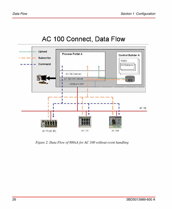
Figure 2. Data Flow of 800xA for AC 100 without event handling
Data Flow Section 1 Configuration
26 3BDS013989-600 A

Section 1 Configuration Configuration workflow and tools
3BDS013989-600 A 27
Configuration workflow and toolsDetailed configuration workflow description on page 41 describes the preparation tasks required to manage Aspect Objects for Advant Controller 100 Series in System 800xA.
The configuration work is mainly done by creating and parametrizing DB Elements in Function Chart Builder. During Generation of Target Code in Function Chart Builder the parameters of the DB Elements relevant for 800xA for AC 100 are automatically transferred to the Bus Configuration Database. The Upload function of the AC 100 AF100 Network object in the Control Structure of Plant Explorer then
Figure 3. Overview 800xA for AC 100 Configuration tools
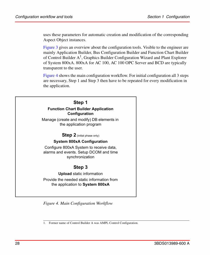
Figure 4. Main Configuration Workflow
Step 1Function Chart Builder Application
ConfigurationManage (create and modify) DB elements in
the application program
Step 2 (initial phase only)
System 800xA ConfigurationConfigure 800xA System to receive data,
alarms and events. Setup DCOM and time synchronization
Step 3Upload static information
Provide the needed static information from the application to System 800xA
Configuration workflow and tools Section 1 Configuration
28 3BDS013989-600 A
uses these parameters for automatic creation and modification of the corresponding Aspect Object instances.
Figure 3 gives an overview about the configuration tools. Visible to the engineer are mainly Application Builder, Bus Configuration Builder and Function Chart Builder of Control Builder A1, Graphics Builder Configuration Wizard and Plant Explorer of System 800xA. 800xA for AC 100, AC 100 OPC Server and BCD are typically transparent to the user.
Figure 4 shows the main configuration workflow. For initial configuration all 3 steps are necessary, Step 1 and Step 3 then have to be repeated for every modification in the application.
1. Former name of Control Builder A was AMPL Control Configuration.

Section 1 Configuration Configuration workflow and tools
3BDS013989-600 A 29
The following is a short description of the 3 Steps shown in Figure 4, for further information see Detailed configuration workflow description on page 41.
Step1: Function Chart Builder Application Configuration
The Aspect Object instances created or modified during upload on System 800xA stem from DB Elements created or modified in Function Chart Builder.
The related DB Elements can be divided into 3 categories:
1. DB Elements which are required with the same set of attributes also for controller configuration,
2. DB Elements which are required also for controller configuration, but have additional terminals to set OPC Server respective Aspect Object attributes and
3. DB Elements which are required only for OPC Server respective System 800xA configuration. These elements have no influence on controller configuration.
That means you can get a basic representation on System 800xA from all connected AC 100 stations without doing any modifications in the controller application code. In this case the DB Elements of category 1 and the DB Elements of category 2 with their default values are the base for the created Aspect Object instances.
Function File > Generate Target Code in Function Chart Builder not only generates the target code to be downloaded to the controller but also populates the Bus Configuration Database (BCD) with AC 100 OPC Server relevant information from the DB Elements.
Step2: System 800xA Configuration
While Step 1 and Step 3 have to be repeated after every modification in relevant DB Elements Step 2 has to be performed only once per AF100 bus.
The Control Structure in the System 800xA, visible in Plant Explorer, describes the structure of the Control Network, its Controllers and Signal Objects.
With this step the top element of the AF100 network in the Control Structure is created. By this object also the communication with the controllers, by selecting the suitable AC 100 OPC Server provider is specified. The AF100 bus number of this

Libraries and Object Types Section 1 Configuration
30 3BDS013989-600 A
network is the Bus Number specified in Configuration Wizard (AF100 Network - AF100 hardware settings) of the OPC Server.
Perform necessary configuration in System 800xA for data, alarms and events. Perform necessary DCOM settings and configuration of Time synchronization.
Step3: Upload static information
The 3rd Step is an automatic upload function which is started by a single mouse click in the Upload aspect of the AC 100 AF100 Network Object instance.
The AC 100 OPC Server uses the Bus Configuration Database file as a source for its knowledge about the Controller objects. When the AC 100 OPC Server is started and after on- and off-line changes it reads the BCD file and builds up a list of objects and their properties. This information is used by the System 800xA software to populate or update the Control structure by instantiating/modifying aspect objects with matching type in the right order in the Control Structure and setting the Name aspect and the Description.
All objects created by the Uploader are instances of the object types presented in Table 1.
Libraries and Object Types800xA for AC 100 defines a set of object types. An object type is a predefined aspect object defined in the Object Type Structure. Object types in 800xA for AC 100 (for example, AC 100 Processor Module and AC 100 AIS) represent the data base element types in the AC 100 series controller.
Each time you have changed the DB part of a controller by creating or deleting DB Elements which correspond to Aspect Objects, or by changing DB Element properties NAME, DESCRIPTION or properties with respect to structure definitions, you need to re-run the Upload to make sure that the objects and object attributes in the Control Structure correspond to the content in the Controllers.
Other DB Element properties, for example UNIT, CLASS or HI_LIM2 do not have any influence on Upload, these properties are updated by subscription.

Figure 5. 800xA for AC 100 Libraries in the Library Structure
Figure 6. Base Library AC100ObjectTypes in the Object Type Structure
Section 1 Configuration Libraries and Object Types
3BDS013989-600 A 31
During upload, the Uploader aspect creates instances of the controller objects with the respective object types in Control Structure.
The 800xA for AC 100 object types are included in libraries in the 800xA system version 5.1 and later versions. The Base Library AC100ObjectTypes defines all object types including the graphics independent aspects. The Extension Library AC100ObjectTypesPG2Ext defines all process graphics aspects in the object types. Extension libraries can be easily activated or deactivated in a functioning system. The extension library can be activated later when required.
A library is in one of the following states, Open, Closed, or Released. After installation of the product, the three libraries are in the Closed state and are
Supported Aspect Object Types Section 1 Configuration
32 3BDS013989-600 A
protected from unintentional modifications. Custom modifications are possible if the library is forced to the Open state. Observe that the modifications may be lost in future system upgrades/updates.
For more information on library handling and object types, refer to the System 800xA, Configuration (3BDS011222*).
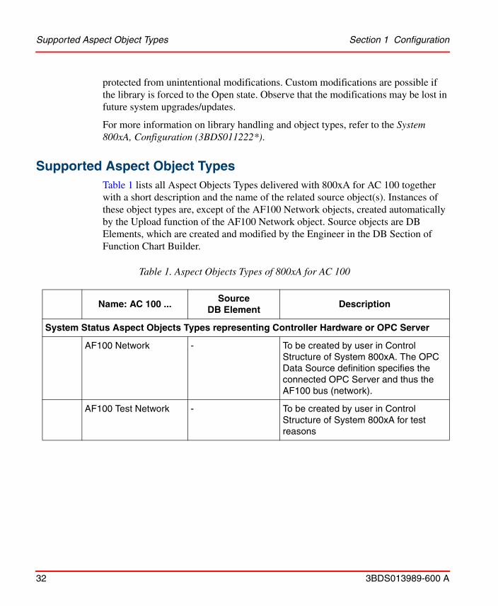
Supported Aspect Object TypesTable 1 lists all Aspect Objects Types delivered with 800xA for AC 100 together with a short description and the name of the related source object(s). Instances of these object types are, except of the AF100 Network objects, created automatically by the Upload function of the AF100 Network object. Source objects are DB Elements, which are created and modified by the Engineer in the DB Section of Function Chart Builder.
Table 1. Aspect Objects Types of 800xA for AC 100
Name: AC 100 ...Source
DB ElementDescription
System Status Aspect Objects Types representing Controller Hardware or OPC Server
AF100 Network - To be created by user in Control Structure of System 800xA. The OPC Data Source definition specifies the connected OPC Server and thus the AF100 bus (network).
AF100 Test Network - To be created by user in Control Structure of System 800xA for test reasons

Section 1 Configuration Supported Aspect Object Types
3BDS013989-600 A 33
AF100 Station An AC 100 node specified in Application Builder or an OPC node specified in Bus Configuration Builder
The AC 100 node is represented in Bus Configuration Database only if at least one ’AF100-Interface’ DB Element for that node exists (CI626, CI627, CI630, CI631, PM810, ...).
The ’BUSNO’ terminal of this DB Element must correspond to the bus number specified in the AC 100 OPC Server of the AF100 Network object (Aspect: OPC Data Source Definition).
AF100 CI Summary CI626, CI627, CI630, CI 631, PM810, ...
Summary Status of the CI elements representing AF100 Bus Coupler towards the System 800xA connected AF100 network.
IO CI Summary PMxxx Summary Status of all IO and CI modules in the AF100 station
PM Summary PMxxx Summary Status of all Processor Modules in the AF100 station
AF100 CI CI626, CI627, CI630, CI631, PM810, CI527A
Currently the same as AF 100 CI Summary (!), in case of an OPC Server station the status of the AF100 interface hardware CI527.
Processor Module PMxxx Status of the Processor Module
OPC - Represents an OPC Server connected to AF100
Signals
AIS AIS Represents the ext. DB Element AIS
Table 1. Aspect Objects Types of 800xA for AC 100 (Continued)
Name: AC 100 ...Source
DB ElementDescription

Supported Aspect Object Types Section 1 Configuration
34 3BDS013989-600 A
DAT_AI DAT_AI
+DAT(R), +DSP
Analog Input Signal with static data from DAT_AI and dynamic value transferred by a DAT(R) within a DSP
AOS AOS Represents the ext. DB Element AOS
DAT_AO DAT_AO
+DAT(R), +DSP
Analog Output Signal with static data from DAT_AO and dynamic value transferred by a DAT(R) within a DSP
DIS DIS Represents the ext. DB Element DIS
DAT_DI DAT_DI
+DAT(B), +DSP
Digital Input Signal with static data from DAT_DI and dynamic value transferred by a DAT(B) within a DSP
DOS DOS Represents the ext. DB Element DOS
DAT_DO DAT_DO
+DAT(B), +DSP
Digital Output Signal with static data from DAT_DO and dynamic value transferred by a DAT(B) within a DSP
Calculated Data
MB MB Represents the ext. DB Element MB
MBS MBS Represents the ext. DB Element MBS
MI MI Represents the ext. DB Element MI
MIL MIL Represents the ext. DB Element MIL
MR MR Represents the ext. DB Element MR
DAT_DAT DAT_DAT
+DAT(x), +DSP
Arbitrary Signal with static data from DAT_DAT and dynamic value transferred by a DAT(x) within a DSP
Table 1. Aspect Objects Types of 800xA for AC 100 (Continued)
Name: AC 100 ...Source
DB ElementDescription
Section 1 Configuration The Control Structure
3BDS013989-600 A 35
The following AC 100 Structure object types serve as grouping objects:
• Grouping of Elements representing System StatusAC 100 Station Status Group, AC 100 Basic Station Group,AC 100 OPC Group
• Grouping of Elements representing SignalsAC 100 AIS Group, AC 100 AOS Group, AC 100 DIS Group,AC 100 DOS Group, AC 100 DAT_AI Group, AC 100 DAT_AO Group,AC 100 DAT_DI Group, AC 100 DAT_DO Group, AC 100 MB Group,AC 100 MBS Group, AC 100 MI Group, AC 100 MIL Group,AC 100 MR Group, AC 100 DAT_DAT Group
The 800xA for AC 100 Aspect Object Types in general support National Languages (NLS), but Conditions and Categories are not supporting NLS.
Instances of these elements are created by the Uploader only if at least one member of the related group is existing in the node.
The Control StructureAF100 Networks are the Control Networks for Advant Controller 100 Series Control Systems. Figure 7 shows the principle construction of the Control Structure part for AF100 Networks.
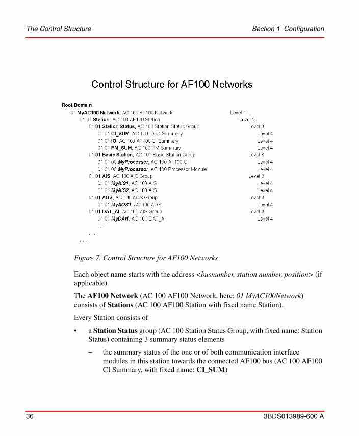
Figure 7. Control Structure for AF100 Networks
The Control Structure Section 1 Configuration
36 3BDS013989-600 A
.
Each object name starts with the address <busnumber, station number, position> (if applicable).
The AF100 Network (AC 100 AF100 Network, here: 01 MyAC100Network) consists of Stations (AC 100 AF100 Station with fixed name Station).
Every Station consists of
• a Station Status group (AC 100 Station Status Group, with fixed name: Station Status) containing 3 summary status elements
– the summary status of the one or of both communication interface modules in this station towards the connected AF100 bus (AC 100 AF100 CI Summary, with fixed name: CI_SUM)
Section 1 Configuration Acknowledge Behavior and Configuration
3BDS013989-600 A 37
– the summary status of all IO and CI modules in this station (AC 100 IO CI Summary, with fixed name: IO)
– the summary status of all processor modules in this station (AC 100 PM Summary, with fixed name: PM_SUM)
• a Basic Station group (AC 100 Basic Station Group, with fixed name: Basic Station) consisting of1
– an AF100 CI object (AC 100 AF100 CI, here: MyProcessor) for every communication interface module in this station towards the connected AF100 bus, in normal case 1 object, in redundant case 2 objects.2
– a Processor Module object (AC 100 Processor Module, here: MyProcessor) for every processor module in this station, in case of AC 160 1..6 objects, for all other controller types 1 object.
• Groups for the different signal and calculated data objects. Group elements without an existing object instance in this station are not created.
Acknowledge Behavior and ConfigurationSignal Aspect Objects from Extended DB Elements (AIS, AOS, DIS, DOS) as well as Signal Aspect Objects from DAT-based Elements (DAT_AI, DAT_DI) may have configured alarms. There are two methods to acknowledge alarms
• Single acknowledge via selecting one single alarm condition in Alarm List
• Object acknowledge, i.e. acknowledging all existing alarms for an object with the same time stamp. This is done by pressing acknowledge button in faceplate, or by selecting Acknowledge in the objects context menu.
When a process object is acknowledged by the operator the acknowledge information is time stamped in the corresponding OPC Server and sent via AF100 to all ’configured’ OPC Servers. To configure this behavior start Bus Configuration Builder, select the appropriate bus and create an AF100 OPC Station for each OPC server node from which alarms may be acknowledged (if not already done). Edit the Station Properties of each of these AF100 OPC Stations and enter the OPC server
1. In case of non redundant stations with one single processor module the status of the object in the station status group equals the status of the corresponding object in the Basic Station group.
2. In case of Advant Controller 70 the AF100 communication interface is integrated in the processor module, the name of the AF100 CI object equals the name of the Processor Module object.

Assume CS1 and CS2 to be the two connectivity servers in a redundant environment with CS1 as active Event Provider and more than 100 unacknowledged alarms present in the Alarm List. After a switch-over of the Event Provider from CS1 to CS2, you may not be able to acknowledge some alarms via the Alarm List. You have to acknowledge them via faceplate.
About the Bus Configuration Database Section 1 Configuration
38 3BDS013989-600 A
nodes to which acknowledgments are to be sent, see 800xA for AC 100/ Advant® OCS, AC 100 OPC Server Configuration and Operation (3BDS013988*). Distribution of acknowledge.
The single acknowledgement of a process object is only valid for the acknowledged Alarm independently of other existing Alarms of the same object.
About the Bus Configuration DatabaseControl Builder A stores all relevant information towards Advant Fieldbus 100 in a Microsoft Access database, called Bus Configuration Database (BCD). This is transparent to the user. When a new project is created in Application Builder an empty database with he datasetname ’projectname’.MDB is created in the project data structure. This database is filled and updated automatically after relevant actions in Function Chart Builder and Bus Configuration Builder.
The path to this database has to be made known to the AC 100 OPC Server within it’s Configuration Wizard by the function OPC Server Path, see 800xA for AC 100/Advant® OCS, AC 100 OPC Server Configuration and Operation (3BDS013988*).
You only have to take care of the Bus Configuration Database if Control Builder A and AC 100 OPC Server have no access to the same data structure, i.e. if they are installed on different PCs and do not have an appropriate network connection.
In this case after every write action you have to copy the MDB-file to the location known and accessible by the AC 100 OPC Server.
National Language SupportThe National Language Support (NLS) is used for translation of application data.
Graphic Aspects

Section 1 Configuration National Language Support
3BDS013989-600 A 39
Translation of graphic aspects texts are made according to the Operator Workplace National Language Support, see System 800xA, Operations, Operator Workplace Configuration (3BSE030322*).
A short example how to change graphic aspects is given below.
1. Select the object in the Object Type Structure.
2. Add NLS Resource Manager Aspect (if not already available)
3. Add the desired locale.
4. Switch to the chosen language, for example, German (Germany).
5. Select all Resource ID's (one after the other) and insert the translated text, for example, “Eingang geblockt” in German.
6. Change language through the Control Panel in Windows.
7. Stop and restart System.
8. Start workplace, select object in Control Structure, for example, select faceplate of object to see the translated text.
All texts which are not translated will remain in the default language English, see Figure 8.
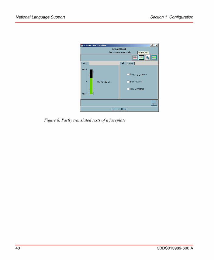
Figure 8. Partly translated texts of a faceplate
National Language Support Section 1 Configuration
40 3BDS013989-600 A

Section 1 Configuration Detailed configuration workflow description
3BDS013989-600 A 41
Alarm and Event Texts
For National Language Support of System Messages, refer to Alarm and Event Texts in 800xA for AC 100/Advant® OCS, OPC Server Configuration and Operation (3BDS013988*).
Detailed configuration workflow description
IntroductionThe following detailed workflow descriptions base on the steps defined in Configuration workflow and tools on page 27 (see Figure 4).
Step1: Function Chart Builder Application Configuration
AC 100 Controller stations are configured for 800xA for AC 100 in Function Chart Builder as described in this step. Yet additional AC 100 OPC Servers have to be specified in Bus Configuration Builder by Edit > Create AF100 OPC Station.
Creation and modification of DB Elements in Function Chart Builder is one of the most common tasks for Engineers configuring Advant Controller 100 Series controller.
How to create and modify DB Elements is described in detail in the Function Chart Builder User’s Guide (3BDS100595*).
The DB Elements in detail are described in the corresponding Database Elements Advant Controller Manuals.
Specifics for Aspect Object configuration are described in Configuration of DB Elements on page 51 later within this section.
Step2: System 800xA Configuration
While Step 1 and Step 3 have to be repeated after every modification in relevant DB Elements, Step 2 has to be performed only once for each AF 100 bus.

Step2: System 800xA Configuration Section 1 Configuration
42 3BDS013989-600 A
Creation of AC 100 AF100 Network Object Instance
1. Open the Plant Explorer Workplace and select Control Structure.
2. Create an instance of the AC 100 AF100 Network object type.
In the Additional Arguments dialog, click Add and select the correct provider (that is, the name of the server where the requested AC 100 OPC Server is installed).
Select the ProgID as ABB.AC100.1 (see Figure 9).
Figure 9. Additional Arguments for the Network Object
3. For a redundant OPC Server, create a new Service Provider object in the existing service group.
Alarm and Event Server Startup in System 800xA
The Alarm and Event Server in System 800xA is not started automatically when 800xA for AC 100 is added to the System 800xA. To start the Alarm and Event server in System 800xA, perform the following steps:
1. Open the Plant Explorer Workplace and select the AC 100 Alarm Provider Service Provider Definition aspect from Service Structure > Event Collector > AC 100 Alarm Server.
2. In the Configuration tab, define the node and click Apply (see Figure 10).
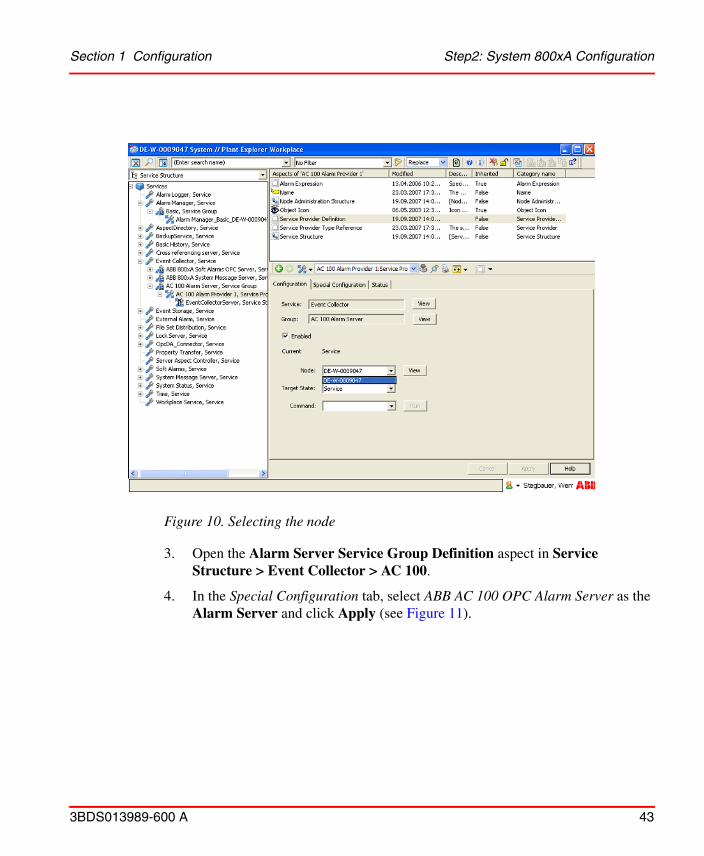
Figure 10. Selecting the node
Section 1 Configuration Step2: System 800xA Configuration
3BDS013989-600 A 43
3. Open the Alarm Server Service Group Definition aspect in Service
Structure > Event Collector > AC 100.
4. In the Special Configuration tab, select ABB AC 100 OPC Alarm Server as the Alarm Server and click Apply (see Figure 11).

Figure 11. Selecting the Alarm Server
Step2: System 800xA Configuration Section 1 Configuration
44 3BDS013989-600 A
5. For a redundant OPC Server, create a new Service Provider object in the
existing service group.
DCOM Settings
DCOM settings must be setup when redundant Connectivity Servers are used.
For connection through DCOM and procedure to use the DCOMCNFG tool to set the DCOM security setting, refer to the Data Access section in System 800xA, Configuration (3BDS011222*).

Section 1 Configuration Step2: System 800xA Configuration
3BDS013989-600 A 45
Setup daylight saving and time synchronization
All PCs in an AF100 network must be configured to the same time zone and must be time synchronized.
There are several alternative ways to configure the clock synchronization for an Advant Fieldbus 100 network together with a network of the System 800xA products.
The Advant Fieldbus 100 network includes a clock synchronization functionality. For information on the configuration and functioning of the clock synchronization, refer to Advant Fieldbus 100 User´s Guide (3BSE000506*) and the corresponding user guide for the Data Base Elements of each controller.
A System 800xA network consists of one or several servers and a number of clients connected through TCP/IP. Synchronization of this network of PCs in itself is supported by System 800xA. For more information, refer to System 800xA, Administration and Security (3BSE037410*). One clock server synchronizes the other PCs in the network.
The AC 100 OPC Server can function as a time master or as a slave versus the Advant Fieldbus 100 network. For information on the configuration, refer to the Configuration section in 800xA for AC 100/Advant® OCS, AC 100 OPC Server Configuration and Operation (3BDS013988*).
Refer to Recommended configuration for the recommended configuration of clock synchronization and daylight saving.
Recommended configuration. It is recommended that you set-up an 800xA Connectivity Server that hosts the AC 100 OPC Server as time master. It will be time master for the System 800xA network and for the Advant Fieldbus 100 network.
Use the Control Panel for making any adjustment to the network time. You can also set time and date using the Command Prompt.
To set-up the System 800xA for this configuration, perform the following:
• Set up the selected server machine as time server. If you have several server machines, set-up the other server machines to request for the correct time from the time server.

Step3: Upload static information Section 1 Configuration
46 3BDS013989-600 A
• Set up all the Workplace nodes to accept the clock synchronization.
• Ensure that automatic daylight saving is set on all the PCs.
• Set up the time synchronization of the AC 100 OPC Server to Master.
Set up the time synchronization of other Advant OPC Servers for Advant Fieldbus 100 to None. These PCs shall collect the time from the time server.
For information on setting the time synchronization, refer to 800xA for AC 100/Advant® OCS, OPC Server Configuration and Operation (3BDS013988*).
The result of this solution for time tagged data is that the Alarm data and Historical data are stored according to UTC time, that is, the local time does not matter. Alarm and History data presentation takes care of presenting data with local time.
Step3: Upload static informationSteps to upload objects are the following:
1. Open the Plant Explorer and select Control Structure.
2. Select the AC 100 AF100 Network object, then select the Uploader aspect.
3. Click Start in the Standard Tab.
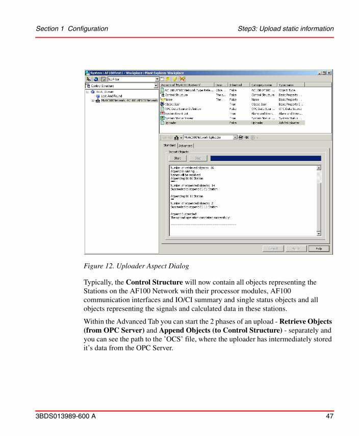
Figure 12. Uploader Aspect Dialog
Section 1 Configuration Step3: Upload static information
3BDS013989-600 A 47
Typically, the Control Structure will now contain all objects representing the Stations on the AF100 Network with their processor modules, AF100 communication interfaces and IO/CI summary and single status objects and all objects representing the signals and calculated data in these stations.
Within the Advanced Tab you can start the 2 phases of an upload - Retrieve Objects (from OPC Server) and Append Objects (to Control Structure) - separately and you can see the path to the ’OCS’ file, where the uploader has intermediately stored it’s data from the OPC Server.

Step3: Upload static information Section 1 Configuration
48 3BDS013989-600 A
Figure 13 shows an example of the Control Structure.
See the relevant sections of System 800xA Plant Engineering Methods Reference Manual (3BSE017088*) on how to create (additional) objects in a structure, how to
Other OPC Stations, which are not physically connected, will not be created by the uploader. In this case a new uploader is needed after the other OPC station is available.
Figure 13. Example of a Control Structure after Upload
Section 1 Configuration Verifying the integration of the uploaded objects
3BDS013989-600 A 49
assign engineering / application data to objects and how to assign objects to other structures.
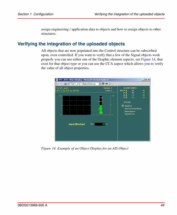
Verifying the integration of the uploaded objectsAll objects that are now populated into the Control structure can be subscribed upon, even controlled. If you want to verify that a few of the Signal objects work properly you can use either one of the Graphic element aspects, see Figure 14, that exist for that object type or you can use the CCA aspect which allows you to verify the value of all object properties.
Figure 14. Example of an Object Display for an AIS Object
Verifying the integration of the uploaded objects Section 1 Configuration
50 3BDS013989-600 A
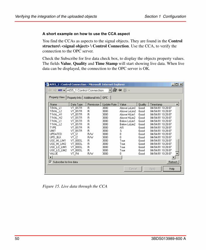
A short example on how to use the CCA aspect
You find the CCAs as aspects to the signal objects. They are found in the Control structure\ <signal object> \ Control Connection. Use the CCA, to verify the connection to the OPC server.
Check the Subscribe for live data check box, to display the objects property values. The fields Value, Quality and Time Stamp will start showing live data. When live data can be displayed, the connection to the OPC server is OK.
Figure 15. Live data through the CCA

Section 1 Configuration Configuration of DB Elements
3BDS013989-600 A 51
Configuration of DB Elements
IntroductionThe Aspect Object instances created and updated by the uploader in the Control Structure mainly stem from the DB Elements created and modified by Function Chart Builder.
The configuration of DB Elements in detail is described in the Function Chart Builder User’s Guide (3BDS100595*).
The relation between the different DB Elements with their actual terminal values and the OPC items with their attributes in OPC Server is described in the 800xA for AC 100/Advant® OCS, OPC Server Configuration and Operation (3BDS013988*). This is also valid for event and alarm generation.
The relation between the OPC items with their attributes in OPC Server and the Properties of the Control Connection Aspect of the Aspect Object instances in the Control Structure of System 800xA is nearly a 1:1 relation. The exact relation can be seen in the OPC tab of the Control Connection Aspect, see Figure 16 with the

Introduction Section 1 Configuration
52 3BDS013989-600 A
Control Connection Aspect Properties of an AC 100 PM Summary object.
Supported Aspect Object Types on page 32 shows the Aspect Object Types of AC 100 Connect subdivided from a functional point of view.
Another possible subdivision of AC 100 Connect Aspect Object Types is based on the amount of extra configuration (engineering) work:
• Aspect Objects which do not require any extra DB Element creation or modification
– Summary Status Objects in the AC 100 Station Status Group1.AF100 CI Summary2.IO CI Summary3.PM Summary
– Single Module Status Objects in the AC 100 Basic Station Group1.AF100 CI2.Processor Module
Figure 16. Control Connection Aspect Properties of a PM_Sum Object

Section 1 Configuration Introduction
3BDS013989-600 A 53
Refer to Objects requiring no extra DB Element configuration on page 56 for a more detailed description.
• Aspect Objects which require DB Element modifications. These are the objects stemming from Extended DB Elements. Only DB Elements with terminal “MMI_USE” = YES are represented in the COntrol Structure of System 800xA.
– Signals from Extended DB Elements1.AIS2.AOS3.DIS4.DOS
– Calculated Data from Extended DB Elements1.MB2.MBS3.MI4.MIL5.MR
Refer to DB Element Configuration with Extended DB Elements on page 59 for a more detailed description.
• Aspect Objects which require extra DB Element and PC Element creations. In this case DAT-based elements are used.
– Signals from DAT-based elements1.DAT_AI2.DAT_AO3.DAT_DI4.DAT_DO
– Calculated Data from DAT-based elements1.DAT_DAT
Refer to DB Element Configuration with Dat-based Elements on page 61 for a more detailed description.

Extended DB Elements versus DAT-based objects Section 1 Configuration
54 3BDS013989-600 A
Extended DB Elements versus DAT-based objectsAll Aspect Object instances in the Control Structure for AC 100 controllers are created by the Uploader. From the subsections above it is visible, that there are object instances representing the hardware - these can be uploaded from arbitrary controller application programs by using the existing programs without further modification - and object instances representing signals and calculated data, coming either from Extended DB Elements1 or from DAT-based DB Elements.
Extended DB Elements
AC 110 and AC 160 controller types support the so-called Extended DB Elements. The Extended DB Elements comprise all elements belonging to a signal or to calculated data, for example
• Signal or data value and status
• A reference to the related IO channel
• Parameters like UNIT or RANGEMIN and RANGEMAX
• Limit supervision, calculated either by the IO channel hardware or by software
• Communication elements towards other processors in the same station (with MDAT elements) and towards Advant Fieldbus 100 (with DSP/DAT elements)
• Alarm and event calculation and distribution
• Parameters for the (Hu-) Man-Machine-Communication MMI via OPC Server
The following extended DB Elements are supported
• Signal Elements
– AIS, AOS, DIS, DOS
• Calculated Data Elements
– MB / MBS, MI, MIL, MR
1. Extended DB Elements are not supported on AC 70 and AC 80.

Section 1 Configuration Extended DB Elements versus DAT-based objects
3BDS013989-600 A 55
DAT-based Elements
If Extended DB Elements are not used the functionality of a signal or of exported or imported calculated data is distributed within the control application.
A signal coming from an IO channel is represented by the related hardware channel DB Element, for example DIS610, while a calculated signal is represented by a corresponding ’calculated’ DB Element, for example DIC.
Calculated Data is typically represented by a DAT DB Element.
A signal or calculated data which shall be exported or imported via AF 100 requires a DataSet DB Element for the transport. In case of a signal in addition a DAT DB Element is required to carry a copy of the actual signal value; this copy has to be supplied by the user application program.
Signals or calculated data from which events shall be generated in addition require an ’AI Calculated’ or ’DI Calculated’ DB Element for event generation and an EventSet DB Element for distribution via AF 100.
To make an AF 100 distributed DAT element and it’s corresponding events known to the OPC Server in addition an MMI (DAT-based) DB Element is required. MMI DB Elements are
• DAT_AI, DAT_AO, DAT_DI, DAT_DO, DAT_DAT
These elements reference the corresponding DAT and EventSet elements and carry additional parameters like UNIT, DESCRIPTION or limit values.
Recommendation
The decision of using Extended DB Elements or DAT-based elements is not only depending on the configuration of the 800xA for AC 100. In case of AC 70 or AC 80 the decision is easy: Extended DB Elements are not supported here.
In case of AC 110 or AC 160 both options are possible.
The main reasons for using Extended DB Elements are
• Object orientedAll information belonging to one signal or calculated data is concentrated in the Extended DB Element.
Objects requiring no extra DB Element configuration Section 1 Configuration
56 3BDS013989-600 A
• Simple transfer and event configurationThe DB Elements required for export (import) and event generation are generated and administrated mainly automatically.
• Extended FunctionalityExamples are status calculation, limit calculation without hardware support and ’update-block’ functionality.
• Simple OPC Server and Connectivity configurationAll required parameters can be specified at the Extended DB Element
The main disadvantages are
• The Extended DB Elements require execution time on the controller
• The Extended DB Elements consume memory on the controller
• The Extended DB Elements may require more AF100 communication load(Extended Elements transfer value and status cyclically, DAT-based only the value).
The processor load for extended DB Elements can be reduced by using the direct access to hardware function (HW_PCDIA = YES).
DAT-based elements require a lot of configuration work with different DB Elements and with additional PC Elements to transfer the data between the DB Elements.
The recommendation is to use Extended DB Elements. DAT-based elements should only be used if
• Extended DB Elements are not supported in the used controller type
• The load on the controller is too high
• It’s not enough memory available on the controller
• The load on AF100 is too high and not all status values are required on system 800xA.
Objects requiring no extra DB Element configurationEvery AC 100 controller application requires independently of AC 100 Connect a suitable Processor Module (PM...) DB Element. And every AC 100 controller
Section 1 Configuration Objects requiring no extra DB Element configuration
3BDS013989-600 A 57
application for a controller connected to AF100 requires independently of AC 100 Connect a suitable Advant Fieldbus 100 (CI...) DB Element.1
From these 2 DB Elements the Uploader of the AC 100 AF100 Network Object creates
the AF100 Station element
• bb ss Station, AC 100 Station
and subordinated the group
• bb ss Station Status, AC 100 Station Status Group
with the elements
– bb ss CI_SUM, AC 100 AF100 CI Summary
– bb ss IO, AC 100 IO CI Summary
– bb ss PM_SUM, AC 100 PM Summary
and the group
• bb ss Basic Station, AC 100 Basic Station Group
with the elements
– bb ss pp CI_NAME, AC 100 AF100 CI
– bb ss pp PM_NAME, AC 100 Processor Module
In Figure 17 AF100 Station 3 on AF100 Bus 1 shows an AC 70 controller node without any extra configuration for 800xA for AC 100 in the application program.
1. In case of Advant Controller 70 the AF100 communication interface is integrated in the processor module.
The following abbreviations are used in this and the following subsections:- bb Bus Number of Advant Fieldbus 100, for example 01- ss Station Number on AF100, for example 01- pp Module position in Controller Station, in case of
- AC 70: = 00 (Combined Processor/CI-Module)- AC 110: for example 01 for PM and 02 for CI626- AC 160: for example 01, 02 for CI630- and 04, 05, 06 for PM-modules

In single processor stations (AC 70 / AC 110) an AC 100 AF100 Station corresponds to one node in Application Builder. In multi processor stations (AC 160) an AC 100 AF100 Station corresponds to 1..8 nodes in Application Builder.
Objects requiring no extra DB Element configuration Section 1 Configuration
58 3BDS013989-600 A
The only requirement is to select “Bus Configuration Database” in the File > Generate Target Code function of Function Chart Builder.
Figure 18 shows an AC 160 controller station 61 with 2 redundant Communication Interfaces towards the connected AF100 and 3 Processor Modules. While in the example of Figure 17 the subdivision into Station (Summary) Status and Basic Station seems to be overdone the example in Figure 18 shows true summary objects representing the complete station and objects for the single Communication Interface and Processor Modules.
Figure 17. AC 70 station without extra configuration for 800xA for AC 100

Figure 18. AC 160 station without extra configuration for 800xA for AC 100
Section 1 Configuration DB Element Configuration with Extended DB Elements
3BDS013989-600 A 59
DB Element Configuration with Extended DB Elements
Extended DB Elements are used for a comfortable, object oriented engineering. These elements combine value and status treatment, limit supervision, event generation, export/import from/to other controllers or OPC Servers and OPC item and attribute configuration.
By means of the Upload function the OPC items and their attributes Name, Description and Type are transferred to Aspect Object instances with corresponding attributes in the Control Structure on System 800xA (this is of course true for all OPC items and not limited to OPC items coming from Extended DB Elements). The created Aspect Object instances have the same name as the corresponding DB Elements. The other attributes can be ’uploaded’ and cyclically updated later on by subscribing mechanisms.
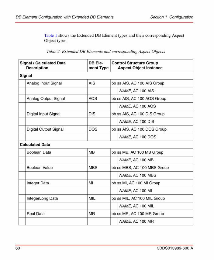
Table 2. Extended DB Elements and corresponding Aspect Objects
Signal / Calculated DataDescription
DB Ele-ment Type
Control Structure GroupAspect Object Instance
Signal
Analog Input Signal AIS bb ss AIS, AC 100 AIS Group
NAME, AC 100 AIS
Analog Output Signal AOS bb ss AIS, AC 100 AOS Group
NAME, AC 100 AOS
Digital Input Signal DIS bb ss AIS, AC 100 DIS Group
NAME, AC 100 DIS
Digital Output Signal DOS bb ss AIS, AC 100 DOS Group
NAME, AC 100 DOS
Calculated Data
Boolean Data MB bb ss MB, AC 100 MB Group
NAME, AC 100 MB
Boolean Value MBS bb ss MBS, AC 100 MBS Group
NAME, AC 100 MBS
Integer Data MI bb ss MI, AC 100 MI Group
NAME, AC 100 MI
IntegerLong Data MIL bb ss MIL, AC 100 MIL Group
NAME, AC 100 MIL
Real Data MR bb ss MR, AC 100 MR Group
NAME, AC 100 MR
DB Element Configuration with Extended DB Elements Section 1 Configuration
60 3BDS013989-600 A
Table 1 shows the Extended DB Element types and their corresponding Aspect Object types.
In principle the DB Element types AIS and DIS can also be used for output signals.
The Aspect Object instances representing Extended DB Elements have the same name as their corresponding Extended DB Element. In opposite to other Aspect Object instance names generated by the Uploader, the names of the Aspect Object instances for Extended DB Elements do not show bus and station number; therefore these names should be unique at least in the scope of the same AF100 bus.
Section 1 Configuration DB Element Configuration with Dat-based Elements
3BDS013989-600 A 61
Every Extended DB Element existing in an AC 100 controller application program is visible in System 800xA if the “MMI_USE”-Terminal of the element equals “YES”.
DB Element Configuration with Dat-based Elements
Process Values and Static Attributes
For better reading the following paragraphs are mainly a repetition of subsection DAT-based Elements on page 55.
A signal coming from an IO channel is represented by the related hardware channel DB Element, for example DIS610, while a calculated signal is represented by a corresponding ’calculated’ DB Element, for example DIC.
Calculated Data is typically represented by a DAT DB Element.
A signal or calculated data which shall be exported or imported via AF 100 requires a DataSet DB Element for the transport. In case of a signal in addition a DAT DB Element is required to carry a copy of the actual signal value; this copy has to be supplied by the user application program.
Signals or calculated data from which events shall be generated in addition require an ’AI Calculated’ or ’DI Calculated’ DB Element for event generation and an EventSet DB Element for distribution via AF 100.
To make an AF 100 distributed DAT element and it’s corresponding events known to the OPC Server in addition an MMI (DAT-based) DB Element is required. Figure 19
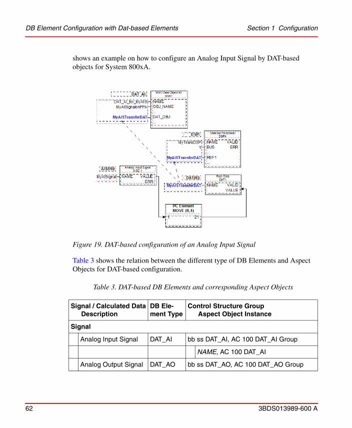
Figure 19. DAT-based configuration of an Analog Input Signal
DB Element Configuration with Dat-based Elements Section 1 Configuration
62 3BDS013989-600 A
shows an example on how to configure an Analog Input Signal by DAT-based objects for System 800xA.
Table 3 shows the relation between the different type of DB Elements and Aspect Objects for DAT-based configuration.
Table 3. DAT-based DB Elements and corresponding Aspect Objects
Signal / Calculated DataDescription
DB Ele-ment Type
Control Structure GroupAspect Object Instance
Signal
Analog Input Signal DAT_AI bb ss DAT_AI, AC 100 DAT_AI Group
NAME, AC 100 DAT_AI
Analog Output Signal DAT_AO bb ss DAT_AO, AC 100 DAT_AO Group
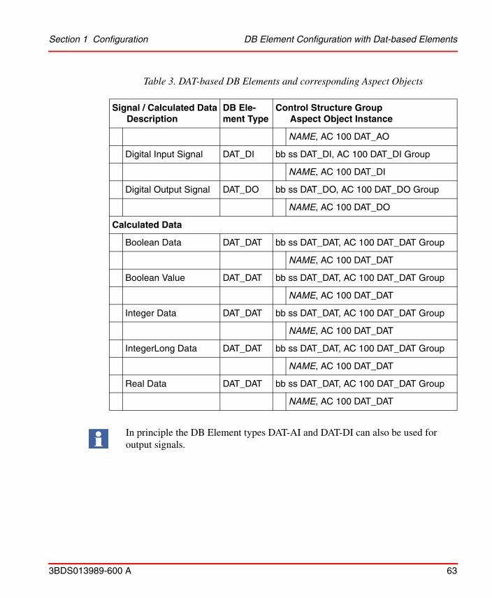
Section 1 Configuration DB Element Configuration with Dat-based Elements
3BDS013989-600 A 63
NAME, AC 100 DAT_AO
Digital Input Signal DAT_DI bb ss DAT_DI, AC 100 DAT_DI Group
NAME, AC 100 DAT_DI
Digital Output Signal DAT_DO bb ss DAT_DO, AC 100 DAT_DO Group
NAME, AC 100 DAT_DO
Calculated Data
Boolean Data DAT_DAT bb ss DAT_DAT, AC 100 DAT_DAT Group
NAME, AC 100 DAT_DAT
Boolean Value DAT_DAT bb ss DAT_DAT, AC 100 DAT_DAT Group
NAME, AC 100 DAT_DAT
Integer Data DAT_DAT bb ss DAT_DAT, AC 100 DAT_DAT Group
NAME, AC 100 DAT_DAT
IntegerLong Data DAT_DAT bb ss DAT_DAT, AC 100 DAT_DAT Group
NAME, AC 100 DAT_DAT
Real Data DAT_DAT bb ss DAT_DAT, AC 100 DAT_DAT Group
NAME, AC 100 DAT_DAT
In principle the DB Element types DAT-AI and DAT-DI can also be used for output signals.
Table 3. DAT-based DB Elements and corresponding Aspect Objects
Signal / Calculated DataDescription
DB Ele-ment Type
Control Structure GroupAspect Object Instance

The status of DAT-based objects in System 800xA represents the communication status for the object. If the status for example of an Analog Input Channel (actual value of Terminal ERR at the AIS element) is required, this value has to be transferred additionally for example by means of a DAT_DAT DB Element and a corresponding DAT(B) DB Element. The status is available on System 800xA then as a separate Aspect Object instance of an AC 100 DAT_DAT type!
DB Element Configuration with Dat-based Elements Section 1 Configuration
64 3BDS013989-600 A
Alarms and Events
Figure 20. Event configuration for DAT-based objects.
Events from analog and digital values are generated on AC 100 controllers by the DB Elements AIC (Analog Input Calculated) and DIC (Digital Input Calculated). To make the events available for an OPC Server - and with this for System 800xA - they have to be buffered and distributed via AF100 by an EventSet DB Element. Figure 20 shows the DB and PC Elements necessary in addition to those in Figure 19 for configuration of events.

Section 1 Configuration Building a Control Structure for Test and Demo Purposes
3BDS013989-600 A 65
Building a Control Structure for Test and Demo PurposesIt may sometimes be an advantage to be able to test or demonstrate your applications versus a simulated Control structure.
You can build a Control Structure with simulated values through the following steps:
1. Select the Control Structure. Build a structure in the Control structure that includes the process and system objects that you want to simulate.
2. Add the aspect Property Signal Generator to each object (process and system object) that you want simulated data from.
Figure 21. Add Aspect Property Signal Generator
Note that the graphic presentation of object data “the faceplates” do not work directly with simulated values from the Property Signal Generator. You must define supervision and presentation properties to get “simulated live data” in the faceplate presentation.
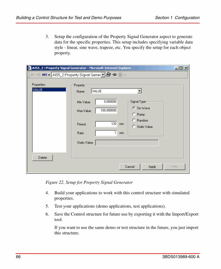
Building a Control Structure for Test and Demo Purposes Section 1 Configuration
66 3BDS013989-600 A
3. Setup the configuration of the Property Signal Generator aspect to generate data for the specific properties. This setup includes specifying variable data style - linear, sine wave, trapeze, etc. You specify the setup for each object property.
Figure 22. Setup for Property Signal Generator
4. Build your applications to work with this control structure with simulated properties.
5. Test your applications (demo applications, test applications).
6. Save the Control structure for future use by exporting it with the Import/Export tool.
If you want to use the same demo or test structure in the future, you just import this structure.
3BDS013989-600 A 67
Section 2 Operation
The majority of the 800xA functionality is generic for all Controller types. The following subsections describe roughly possibilities with 800xA for AC 100 regarding plant operation and some details about the control system status of AC 100 Control Systems.
Operating the Plant
Viewing Process ValuesViewing of actual values from the process is performed by standard System 800xA functions.
Common mediums are
• Faceplates (Faceplate Elements)
• Graphic Displays (Graphic Elements)
• Trend Display
• Property View of Control Connections
Viewing Events and Alarms from the ProcessViewing of Events and Alarms from the process is performed by standard System 800xA functions.
Common mediums are
• Alarm List Displays
• Event List Displays
Giving Commands Section 2 Operation
68 3BDS013989-600 A
Acknowledgement is performed via Alarm List displays and Faceplates.
Giving CommandsGiving Commands means to change actual values in the application program on the connected controllers, which then may for example change control parameters or may be moved directly to an output device. Giving Commands is performed by standard System 800xA functions.
Common mediums are
• Faceplates (Faceplate Elements)
• Graphical Elements integrated into own process displays
In case of signals the element first has to be blocked to avoid (cyclic) update from
• the process in case if input signals
• the control logic in case of output signals
FaceplatesFaceplates are graphical display and control elements available in adapted form for the different 800xA for AC 100 Signal and Calculated Data Aspect Object Types.
The Faceplates are divided into different areas to enable the operator to easily find the information and operate the objects. The objects all look the same to the operator and the different faceplate types have the same areas at the same place in the framework. They are all grouped so that the most important information is located at the top of the faceplate, then going downwards to the least important information at the bottom of the faceplate.
In case of DAT-based Signals the logic to block the signal is neither included in the implementation on the controller nor in the implementation of the Aspect Objects of 800xA for AC 100. This functionality has to be added by separate configuration on the controller (resp. Control Builder A) and if required within for example one faceplate also on the System 800xA.

Section 2 Operation Faceplates
3BDS013989-600 A 69
The different views of a Faceplate can change the size or look of the Status and Navigation bar area, the Faceplate element area and the Button area.
800xA for AC 100 delivers faceplates for all 800xA for AC 100 Signal and Calculated Data Aspect Object Types in up to 3 views
• Extended View
• Normal View
• Reduced View
Figure 23. Faceplate Principles.
Header area
Status andnavigation area
Operation
View selection buttons
Faceplate element
Apply buttonbutton area
area which givesprocess information
Display Links

Faceplates Section 2 Operation
70 3BDS013989-600 A
An Alarm Control symbol will be visible in the header area if the Object is in an alarm state.
The symbol can indicate different alarm states, for example Disturbance and unacknowledged alarms. It is also possible to acknowledge the object alarms with this symbol.
The Alarm Control has the following states:
Figure 24. AIS Faceplate showing an error.
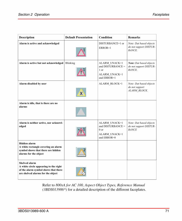
Description Default Presentation Condition Remarks
Alarm is active and acknowledged DISTURBANCE=1 or
ERROR=1
Note: Dat based objects do not support DISTUR-BANCE.
Alarm is active but not acknowledged Blinking ALARM_UNACK=1 and DISTURBANCE = 1 or
ALARM_UNACK=1 and ERROR=1
Note: Dat based objects do not support DISTUR-BANCE.
Alarm disabled by user ALARM_BLOCK=1 Note: Dat based objects do not support ALARM_BLOCK.
Alarm is idle, that is there are no alarms
Alarm is neither active, nor acknowl-edged
ALARM_UNACK=1 and DISTURBANCE = 0 or
ALARM_UNACK=1 and ERROR=0
Note: Dat based objects do not support DISTUR-BANCE
Hidden alarmA white rectangle covering an alarm symbol shows that there are hidden alarms for the object
Shelved alarmA white circle appearing to the right of the alarm symbol shows that there are shelved alarms for the object
Section 2 Operation Faceplates
3BDS013989-600 A 71
Refer to 800xA for AC 100, Aspect Object Types, Reference Manual (3BDS013986*) for a detailed description of the different faceplates.

Object Displays Section 2 Operation
72 3BDS013989-600 A
Object DisplaysObject Displays are graphical overview display elements available for the different signal Aspect Object Types and for the MBS Aspect Object Types.
Figure 25 shows as example the object display of an AIS Aspect Object. Available are the current value numerically and as a bargraph, a trend display and different states of the object.
Refer to 800xA for AC 100, Aspect Object Types, Reference Manual (3BDS013986*) for a detailed description of the different Object Displays.
Figure 25. AIS Object Display

Section 2 Operation Trend Displays
3BDS013989-600 A 73
Trend DisplaysTrend Displays provide a graphical view of the last values of a measured value, showing the trend of the value. The trend display can also be configured to show historical data.
Graphical ElementsGraphical Elements can be used as predefined elements in self configured process displays.
Graphical Elements are available in different variants for the different 800xA for AC 100 Aspect Object Types:
• BargraphMV showing the measured value as a bargraph
• NumericMV showing the measured value numerically
• IndicatorBox showing the digital state of the measured value
• UnitMV showing the unit of the measured value
• System Status Overview showing a summer status of the object
Figure 26 shows an example of a Graphical Element for an Indicator Box in case of a FALSE value the inner rectangle is black, in case of a TRUE value the complete rectangle is green.
Figure 26. Example of an Indicator Box
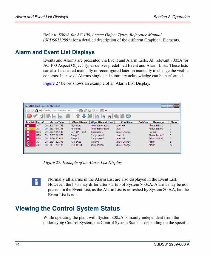
Alarm and Event List Displays Section 2 Operation
74 3BDS013989-600 A
Refer to 800xA for AC 100, Aspect Object Types, Reference Manual (3BDS013986*) for a detailed description of the different Graphical Elements.
Alarm and Event List DisplaysEvents and Alarms are presented via Event and Alarm Lists. All relevant 800xA for AC 100 Aspect Object Types deliver predefined Event and Alarm Lists. These lists can also be created manually or reconfigured later on manually to change the visible contents. In case of Alarms single and summary acknowledge can be performed.
Figure 27 below shows an example of an Alarm List Display.
Viewing the Control System StatusWhile operating the plant with System 800xA is mainly independent from the underlaying Control System, the Control System Status is depending on the specific
Figure 27. Example of an Alarm List Display
Normally all alarms in the Alarm List are also displayed in the Event List. However, the lists may differ after startup of System 800xA. Alarms may be not present in the Event List, as the Alarm List is refreshed by System 800xA, but the Event List is not.

Section 2 Operation System Status Information from AC 100 Control Systems
3BDS013989-600 A 75
design and properties of the AC 100 Control System. Nevertheless the presentation functions (System Status Viewer / Reporter and System Event List Displays) are the same for different Control Systems.
The System Status presents the status of the control system, that is the results from the control systems and the AC 100 OPC Server´s internal supervision programs. A complete overview of the System Status for the control system is available in the Network node.
System Status Information from AC 100 Control SystemsSystem Status information is available - like Process Values - as properties of the Control Connection Aspect. Therefore System Status information can be made visible like Process Values for example in Graphic Displays.
System Status Objects are all objects describing the system status and the system structure. The System Status Objects are
• bb ss Station Status (Type: AC 100 Station Status Group)
• bb ss Basic Station (Type: AC 100 Basic Station Group)
While the Station Status describes the summary status of the complete station, consisting of
• bb ss CI_SUM (Type: AC 100 AF100 CI Summary)
• bb ss IO (Type: AC 100 IO CI Summary)
• bb ss PM_SUM (Type: AC 100 PM Summary)
the Basic Station describes the status of single modules in the basic station of the controller
• bb ss pp CI_Name (Type: AC 100 AF100 CI)
• bb ss pp PM_Name (Type: AC 100 Processor Module)
The following abbreviations are used- bb Bus Number of Advant Fieldbus 100, for example 01- ss Station Number on AF100, for example 01- pp Module position in Controller Station, in case of
- AC 70: = 00 (Combined Processor/CI-Module)- AC 110: for example 01 for PM and 02 for CI626- AC 160: for example 01, 02 for CI630- and 04, 05, 06 for PM-modules
System Status Information from AC 100 Control Systems Section 2 Operation
76 3BDS013989-600 A
The System Status objects and their properties available depend on the type and on the configuration of the connected station:
• AC 70
– The AC 100 AF100 CI Summary and the AC 100 AF100 CI object represent the AF100 communication part of the Processor Module (PM810)
– The AC 100 PM Summary and the AC 100 Processor Module object represent the application processor part of the Processor Module (PM810)
• AC 110
– The AC 100 AF100 CI Summary and the AC 100 AF100 CI object represent the CI626 or CI627 module, which connects the station to AF100 Network
– The AC 100 PM Summary and the AC 100 Processor Module object represent the Processor Module (PM632, PM633 or PM634).
• AC 160
– The AC 100 AF100 CI Summary object represents the one or, in case of redundancy, both CI module(s), which connect(s) the station to the AF100 Network
– The AC 100 PM Summary object represents all Processor Modules (PM6xx) in this station
– The AC 100 AF100 CI object is instantiated once for every present CI626, CI627, CI630 or CI631 module, which connects the station to AF100 Network

Section 2 Operation System Status Information from AC 100 Control Systems
3BDS013989-600 A 77
– The AC 100 Processor Module object is instantiated once for every present Processor Module (PM6xx)
• OPC StationA PC connected via AF100 Interface hardware to the AF100 network and with running AC 100 OPC Server is visible as an OPC Station. An OPC Station is only visible as a Basic Station, there is no Station Status. In case of redundancy both redundant OPC Servers are visible as single OPC Stations.
– The AC 100 AF100 CI object represent the CI527A status
– The AC 100 Processor Module object represent the OPC Server software
In all cases, except for OPC stations, the AC100 IO CI Summary object represents the summary status of all hardware modules in the station. This status consists of 2 boolean values
• Peripheral Hardware Error caused by IO or CI module(s): PEE
• Process Error caused by IO module(s): PRE
The subdivision into Station Status and Basic Station is wise only in case of AC 160 controller stations: there may be multi processor modules and/or there may be pairs of redundant AF100 communication interfaces and/or processor modules.
The example in Figure 28 shows all System Status Objects for an
• AC 70 station (01 01)
• OPC Server station (01 11)
• AC 160 station (01 61) with redundant CI630 and 3 Processor Modules

System Status Information from AC 100 Control Systems Section 2 Operation
78 3BDS013989-600 A
Figure 28. System Status Objects in the Control Structure
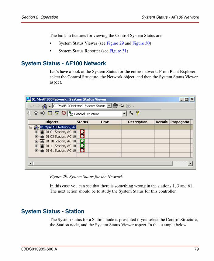
Section 2 Operation System Status - AF100 Network
3BDS013989-600 A 79
The built-in features for viewing the Control System Status are
• System Status Viewer (see Figure 29 and Figure 30)
• System Status Reporter (see Figure 31)
System Status - AF100 Network
Figure 29. System Status for the Network
Let’s have a look at the System Status for the entire network. From Plant Explorer, select the Control Structure, the Network object, and then the System Status Viewer aspect.
In this case you can see that there is something wrong in the stations 1, 3 and 61. The next action should be to study the System Status for this controller.
System Status - StationThe System status for a Station node is presented if you select the Control Structure, the Station node, and the System Status Viewer aspect. In the example below

System Status - Station Section 2 Operation
80 3BDS013989-600 A
(Figure 30), the controller in station 1 has a problem with it´s PM Board.
It is possible to get a detailed view of the properties at the summary objects CI_SUM, IO and PM_SUM if the Details column is marked with an X. To present a detailed view select it in the System Status Viewer and double-click on the line (see Figure 31).
Figure 30. System Status View for Station node

Section 2 Operation System Status - OPC Objects
3BDS013989-600 A 81
In addition you can have a look at the System Status for the modules (AF100 CIs and Processor Modules) in the Basic Station.
An alternative action in fault finding is to study the system alarm list for the failing Station, see System Events from AC 100 Control Systems on page 82.
System Status - OPC ObjectsThere is one OPC system status object for each OPC Server1 in the network. It is possible to get a detailed view of the properties for a specific OPC Server if the Details column is marked with an X. To present a detailed view for an OPC Server, select it in the System Status Viewer and click on the Details button. See Figure 32 and the AC 100 OPC Server Configuration and Operation for details on the status properties.
Figure 31. Detailed View for PM_SUM object
1. Node types with AdvaSoft 1.x software installed will show up as OPC objects. The status information will then be very limited.

Figure 32. System Status View for an OPC Object
System Events from AC 100 Control Systems Section 2 Operation
82 3BDS013989-600 A
System Events from AC 100 Control Systems
The AC 100 Controllers produce a number of event and alarm messages to inform you about errors concerning the AC 100 system and not with the process itself.
You can find a System Event List aspect on all System Status Objects. The System Event List aspect enables you to see all system events for the AC 100 controllers and for the connected AC 100 OPC Servers.
The System Events are presented in plain text, see for example Figure 33.
System Alarm List and System Event List are available on the AF 100 Network object in the Control Structure.
The System Events provide valuable information for fault tracing.
Events from System Status Objects are time stamped in the OPC server. For that reason different AC 100 OPC Servers may present different time for the same event.
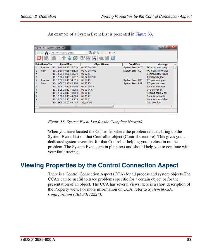
Section 2 Operation Viewing Properties by the Control Connection Aspect
3BDS013989-600 A 83
An example of a System Event List is presented in Figure 33.
When you have located the Controller where the problem resides, bring up the System Event List on that Controller object (Control structure). This gives you a dedicated system event list for that Controller helping you to close in on the problem. The System Events are in plain text and should help you to continue with your fault tracing.
Viewing Properties by the Control Connection AspectThere is a Control Connection Aspect (CCA) for all process and system objects.The CCA:s can be useful to trace problems specific for a certain object or for the presentation of an object. The CCA has several views, here is a short description of the Property view. For more information on CCA, refer to System 800xA, Configuration (3BDS011222*).
Figure 33. System Event List for the Complete Network
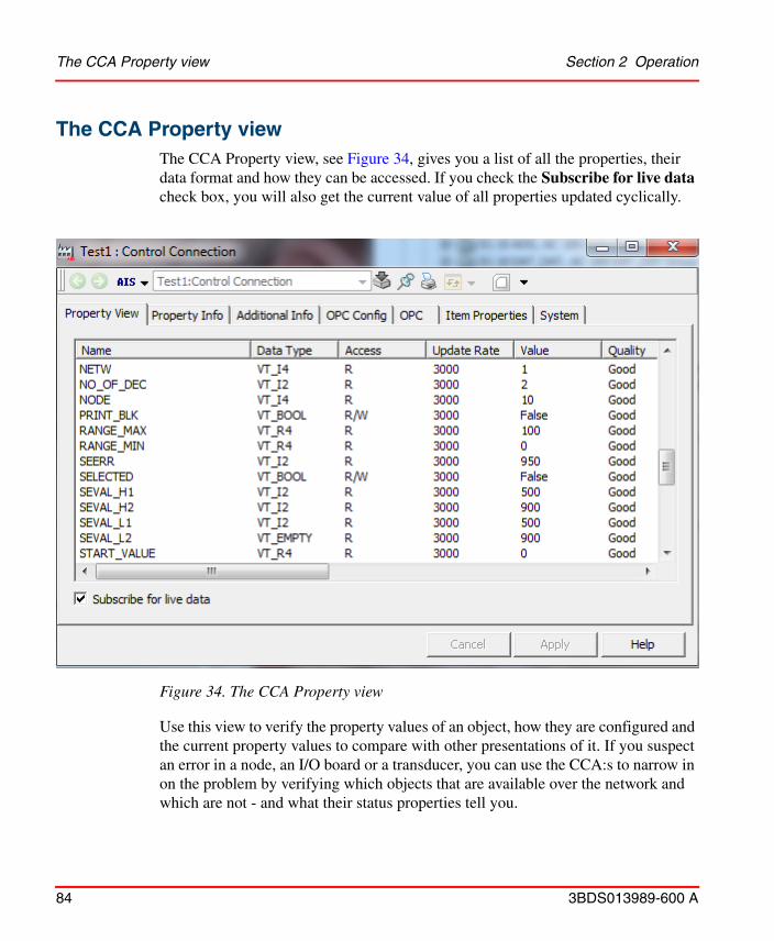
The CCA Property view Section 2 Operation
84 3BDS013989-600 A
The CCA Property view
Figure 34. The CCA Property view
The CCA Property view, see Figure 34, gives you a list of all the properties, their data format and how they can be accessed. If you check the Subscribe for live data check box, you will also get the current value of all properties updated cyclically.
Use this view to verify the property values of an object, how they are configured and the current property values to compare with other presentations of it. If you suspect an error in a node, an I/O board or a transducer, you can use the CCA:s to narrow in on the problem by verifying which objects that are available over the network and which are not - and what their status properties tell you.

The CCA Property view gives you a complete list of properties for example their names, data type, permission, value and quality.
Section 2 Operation Preventive Maintenance
3BDS013989-600 A 85
Preventive MaintenanceThe software product does not require any preventive maintenance. Refer to the 800xA for AC 100, OPC Server, Configuration and Operation (3BDS013988*) about Preventive Maintenance for the communication hardware board CI527A.
Backup/Restore ProceduresGeneral backup procedures are described in the System 800xA, Operations, Operator Workplace Configuration (3BSE030322*).

Backup/Restore Procedures Section 2 Operation
86 3BDS013989-600 A
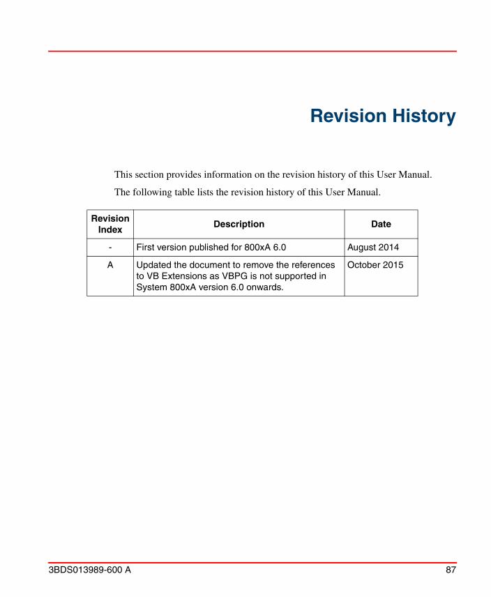
3BDS013989-600 A 87
Revision History
This section provides information on the revision history of this User Manual.
The following table lists the revision history of this User Manual.
Revision Index
Description Date
- First version published for 800xA 6.0 August 2014
A Updated the document to remove the references to VB Extensions as VBPG is not supported in System 800xA version 6.0 onwards.
October 2015

88 3BDS013989-600 A
3BDS013989-600 A 89
AABB Master Programming Language 14AC 14AC 100 Controller Integration 11ACC 14Advant Controller 14Advant Fieldbus 100 14Advant OCS 14AMPL 14AMPL Control Configuration 14APB 14Application Builder 14
BBackup and Restore 85BCB 14BCD 15BCI 15Bus Configuration Builder 14Bus Configuration Database 15
BCD.MDB 30Bus Configuration Interface 15
CCBA 15CI Board 15Client Application 15Clock Master 15COM 15Component Object Model 15Configuration
Before you start 11Control Builder A 15
Control Connection AspectProperty view 84
DDAT Based Objects 15DataSet Peripheral (DSP) 16DB Element 16DCOM 16Distributed COM 16DSP 16
EElectrostatic Discharge 16ESD 16Event Sets 16EVS 16Extended DB Elements 16 to 17
FFCB 16Function Chart 16Function Chart Builder 16
HHardware indicators 85HMI 16HSI 16Human Machine Interface (HMI) 16Human System Interface 16
LLED 16Light Emitting Diode 16
Index
Index
90 3BDS013989-600 A
MMan Machine Interface 16MMI 16
OObject (Process) 16OPC 17Operations 67Operator Station 17OS 17
PPC 17PC Element 17PC Program 17PCPGM 17Personal Computer 17Preventive maintenance 85
SSDP 17Service Data Protocol (SDP) 17Simulated process data
Export control structure 66Import control structure 66Property signal generator 65
System AlarmsAlarm list for Controllers 83Alarm list for network 83
System StatusController node 79Network 79OPC Objects 81
TTerminology 13
UUploader 46
XXDB 17


Power and productivity for a better worldTM
Contact us
Copyright © 2015 ABB.All rights reserved.
3BD
S01
3989
-600
Awww.abb.com/800xAwww.abb.com/controlsystems