800W Mini Hi-Fi System FWM663 - gip-woox.com.br 785 35420.pdf · • Subwoofer type: Passive Audio...
30
Version 1.0 FWM663 3141 785 35420 800W Mini Hi-Fi System -/55/77/BK Published by LX 1029 Service Audio Subject to modification © Copyright 2010 Philips Consumer Electronics B.V. Eindhoven, The Netherlands All rights reserved. No part of this publication may be reproduced, stored in a retrieval system or transmitted, in any form or by any means, electronic, mechanical, photocopying, or otherwise without the prior permission of Philips. CONTENTS Technical specification ..................................................................1-2 Version variation ...........................................................................1-2 Service measurement setup..........................................................1-3 Service aids .................................................................................1-4 Instructions on CD playability ................................................2-1..2-2 Block diagram ................................................................................ 3-1 Wiring diagram .............................................................................. 4-1 Disassembly diagram............ ................................................5-1..5-2 Main board Circuit diagram ......................................................................... 6-1 Layout diagram ..................................................................6-2..6-3 Display board Circuit diagram ..................................................................7-1..7-2 Layout diagram ..................................................................7-3..7-4 USB/SD board Circuit diagram ......................................................................... 8-1 Layout diagram ......................................................................... 8-2 AMP Board Circuit diagram. .................................................................9-1..9-2 Layout diagram ..................................................................9-3..9-4 CD board Circuit diagram ....................................................................... 10-1 Layout diagram ..............................................................10-2..10-3 MCU Board Circuit diagram. ...................................................................... 11-1 Layout diagram .............................................................. 11-2..11-3 Exploded view diagram ............................................................... 12-1
Transcript of 800W Mini Hi-Fi System FWM663 - gip-woox.com.br 785 35420.pdf · • Subwoofer type: Passive Audio...

Version 1.0
FWM663
3141 785 35420
800W Mini Hi-Fi System-/55/77/BK
Published by LX 1029 Service Audio Subject to modification
© Copyright 2010 Philips Consumer Electronics B.V. Eindhoven, The NetherlandsAll rights reserved. No part of this publication may be reproduced, stored in a retrievalsystem or transmitted, in any form or by any means, electronic, mechanical, photocopying,or otherwise without the prior permission of Philips.
CONTENTS
Technical specification ..................................................................1-2Version variation ...........................................................................1-2 Service measurement setup..........................................................1-3 Service aids .................................................................................1-4 Instructions on CD playability ................................................2-1..2-2
Block diagram ................................................................................3-1Wiring diagram ..............................................................................4-1 Disassembly diagram............ ................................................5-1..5-2
Main board Circuit diagram .........................................................................6-1 Layout diagram ..................................................................6-2..6-3
Display board Circuit diagram ..................................................................7-1..7-2 Layout diagram ..................................................................7-3..7-4
USB/SD board Circuit diagram .........................................................................8-1 Layout diagram .........................................................................8-2
AMP Board Circuit diagram. .................................................................9-1..9-2 Layout diagram ..................................................................9-3..9-4
CD board Circuit diagram .......................................................................10-1 Layout diagram ..............................................................10-2..10-3
MCU Board Circuit diagram. ......................................................................11-1 Layout diagram ..............................................................11-2..11-3
Exploded view diagram ...............................................................12-1

Sound• Total Sound Power (RMS): 800 W• Output Power: 9900W PMPO• Sound Enhancement: MAX Sound, Dynamic Bass
Boost 3 steps, Incredible Surround, Digital SoundControl 4 modes, Virtual Ambience Control
Loudspeakers• Number of Loudspeakers: 3• Main Speaker: 2" tweeter, Bass Reflex Speaker
System, 2 way• Subwoofer driver: 10" woofer• Subwoofer type: Passive
Audio Playback• Loader Type: 3 CD Carousel• Number of Discs: 3• Playback Media: CD, CD-R, CD-RW, MP3-CD,
WMA-CD, SD Card, USB flash drive• Disc Playback Modes: 40-Track Programmable,
Repeat/one/disk/program, Shuffle Play• USB Direct / SD Modes: Fast Backward/Fast
Forward, Play/Pause, Previous/Next, Repeat,Shuffle
Audio Recording• Recording Media: USB device, SD/MMC card• USB recording sources: CD, Tuner, Microphone
in, Aux, SD Card• SD card recording sources: Aux, CD, Microphone
in, Tuner, USB device• USB / SD card recording modes: Delete, Instant
record, Progammed tracks, Schedule radioprogram, Single disc, Single track
Tuner/Reception/Transmission• Auto digital tuning• Station presets: 40
• Tuner Bands: FM, MW• Tuner Enhancements: Auto Store, Easy Set (Plug &
Play)
Connectivity• Audio Connections: RCA Aux in, 3.5mm stereo
line in -MP3 link• USB: USB host• Microphone: Dual Microphone sockets• Other connections: FM Antenna, MW Antenna
Convenience• Alarms: CD Alarm, USB alarm, Radio Alarm, Sleep
timer• Clock: On main display• Display Type: FTD• Karaoke: MIC volume, Echo control
Accessories• Remote control: 36-key with 2xAAA batteries• User Manual: Spanish, B-Portuguese• Quick start guide: Spanish, B-Portuguese• Guarantee booklet: Global version• Included accessories: FM/MW Antenna, Batteries
for remote control, *Flat pin adaptor• Cables: MP3 line-in cable
Dimensions• Set dimensions (W x H x D): 265 x 359 x 353 mm• Main speaker dimensions (W x H x D):
263 x 447 x 360 mm• Subwoofer dimensions (W x H x D):
337 x 491 x 360 mm• Packaging dimensions (W x H x D):
791 x 562 x 741 mm• Weight incl. Packaging: 35.2 kg
Power• Power supply: 100-240VAC, 50/60Hz
TECHNICAL SPECIFICATION
1 - 2
Type /Versions:
Features
Board in used:
FWM663
Service policy
MAIN BOARD
* TIPS : C -- Component Lever Repair.M -- Module Lever Repair
-- Used
/55 /00 /77 89/39/KB/
Feature diffrenceRDSVOLTAGE SELECTORECO STANDBY - DARK
Type /Versions: FWM663
/55 /00 /77 89/39/KB/
VERSION VARIATION
C/M
AMP BOARD
49/
C/MC/MC/M
C/M
C/MC/MC/M
C/MC/M
C/M
C/M
C/M
C/MC/MC/M
C/M
C/M
49/
DISPLAY BOARDCD BOARDMCU BOARD
USB BOARD
SD BOARD C/MC/M C/M
1-3
LF Generator e.g. PM5110
RecorderUse Universal Test Cassette CrO2 SBC419 4822 397 30069
LEVEL METERe.g. Sennheiser UPM550
with FF-filter
S/N and distortion metee.g. Sound Technology ST170
L
R
DUT
or Universal Test Cassette Fe SBC420 4822 397 30071
LEVEL METERe.g. Sennheiser UPM550
with FF-filter
S/N and distortion metere.g. Sound Technology ST1700B
L
R
DUT
CDUse Audio Signal Disc(replaces test disc 3)
SBC429 4822 397 30184
Bandpass250Hz-15kHz
e.g. 7122 707 48001LF Voltmeter
e.g. PM2534DUT
S/N and distortion meter e.g. Sound Technology ST1700B
Frame aeriale.g. 7122 707 89001
Tuner AM (MW,LW)
To avoid atmospheric interference all AM-measurements have to be carried out in a Faraday´s cage.Use a bandpass filter (or at least a high pass filter with 250Hz) to eliminate hum (50Hz, 100Hz).
RF Generator e.g. PM5326
Ri=
50
Bandpass250Hz-15kHz
e.g. 7122 707 48001LF Voltmeter
e.g. PM2534DUT
RF Generator e.g. PM5326
S/N and distortion meter e.g. Sound Technology ST1700B
Use a bandpass filter to eliminate hum (50Hz, 100Hz) and disturbance from the pilottone (19kHz, 38kHz).
Ri=
50
Tuner FM
MEASUREMENT SETUP

1-4
SERVICE AIDS
GB WARNINGAll ICs and many other semi-conductors aresusceptible to electrostatic discharges (ESD).Careless handling during repair can reduce lifedrastically.When repairing, make sure that you areconnected with the same potential as the massof the set via a wrist wrap with resistance.Keep components and tools also at thispotential.
ESD
CLASS 1LASER PRODUCT
GBSafety regulations require that the set be restored to its originalcondition and that parts which are identical with those specified,be usedSafety components are marked by the symbol ! .
Lead free
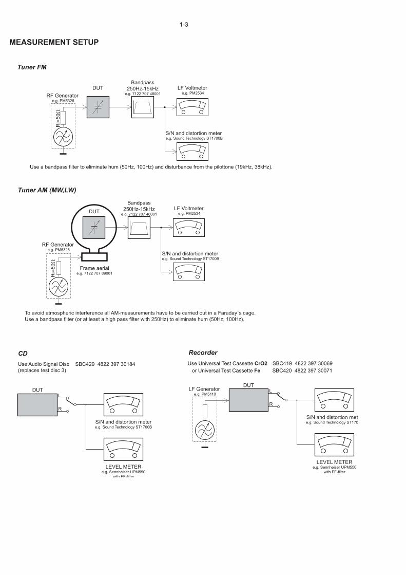
Set remains closed!
N
Y
Play a CD for at least 10 minutes
Y
playabilityok ?
Nplayabilityok ?
add Info for customer"SET OK"
check playability
N
Y
playabilityok ?
check playability
check playability
return set
Customer complaint"CD related problem"
"fast" lens cleaning
1
2
3For flap loaders (= access to CD drive possible)cleaning method 4 is recommended
INSTRUCTIONS ON CD PLAYABILITY
2 - 1
Exchange CDM
1 - 4 For description - see following pages

1PLAYABILITY CHECK
For sets which are compatible with CD-RW discsuse CD-RW Printed Audio Disc ....................7104 099 96611
TR 3 (Fingerprint)TR 8 (600μ Black dot) maximum at 01:00
• playback of these two tracks without audible disturbanceplaying time for: Fingerprint 10seconds
Black dot from 00:50 to 01:10• jump forward/backward (search) within a reasonable time
For all other sets use CD-DA SBC 444A..................................4822 397 30245
TR 14 (600μ Black dot) maximum at 01:15TR 19 (Fingerprint)TR 10 (1000μ wedge)
• playback of all these tracks without audible disturbanceplaying time for: 1000μ wedge 10seconds
Fingerprint 10secondsBlack dot from 01:05 to 01:25
• jump forward/backward (search) within a reasonable time
2CUSTOMER INFORMATION
It is proposed to add an addendum sheet to the set whichinforms the customer that the set has been checkedcarefully - but no fault was found.The problem was obviously caused by a scratched, dirty orcopy-protected CD. In case problems remain, the customeris requested to contact the workshop directly. The lens cleaning (method 3) should be mentioned in theaddendum sheet.
The final wording in national language as well as the printingis under responsibility of the Regional Service Organizations.
4LIQUID LENS CLEANING
Because the material of the lens is synthetic and coatedwith a special anti-reflectivity layer, cleaning must be donewith a non-aggressive cleaning fluid. It is advised to use“Cleaning Solvent
The actuator is a very precise mechanical component andmay not be damaged in order to guarantee its full function.Clean the lens gently (don’t press too hard) with a soft andclean cotton bud moistened with the special lens cleaner.
The direction of cleaning must be in the way as indicated inthe picture below.
Before touching the lens it is advised to clean thesurface of the lens by blowing clean air over it.This to avoid that little particles make scratches onthe lens.
INSTRUCTIONS ON CD PLAYABILITY
2 - 2

BLOCK DIAGRAM3-1 3-1
CD SERVO BU9543
RL
RR
MLC3895 144pin QFP
INPUT
RC5/RC6 CODE
VFDPT6315&
KEY PART
MAIN L/R
INPUT
SENSOR
16M SDRAM
8M SERIAL FALSH
SST29VF080B
PICK UP
MOTOR
ADC WM8782
3CDCDRIVER ICTDA7073A
MUX74LVC157
AUX
TUENRPACK
MICROPHONE
USB/SD
MOTOR DRIVER BA5826
IIC
MU
L-L/
R
IIC
PCMBCK,LRCK
,DATEPCM
CD
L/R
TUNER L/R
CONTROL DATA
CD PCM BCK,LRCK,
DATE
TDA8954*2
FUNCTION IC TDA7468D
3CD LOADER
TDA8954*1 SUB/R
2*250W
1*300W
AMP BOARD
MAIN BOARD
KEY CONTROL BOARD
SOUND KEY CONTROL BOARD
VOLUME CONTROL BOARD
VFD BOARD
MCU BOARD
SD BOARD
CD MECHANIC
CLOSE/OPEN-MOTOR BOARD 3CDC-MOTOR BOARD
TUNER BOARD
CD BOARD
PO
WE
R S
UP
PLY
POW
ER C
ON
NEC
T
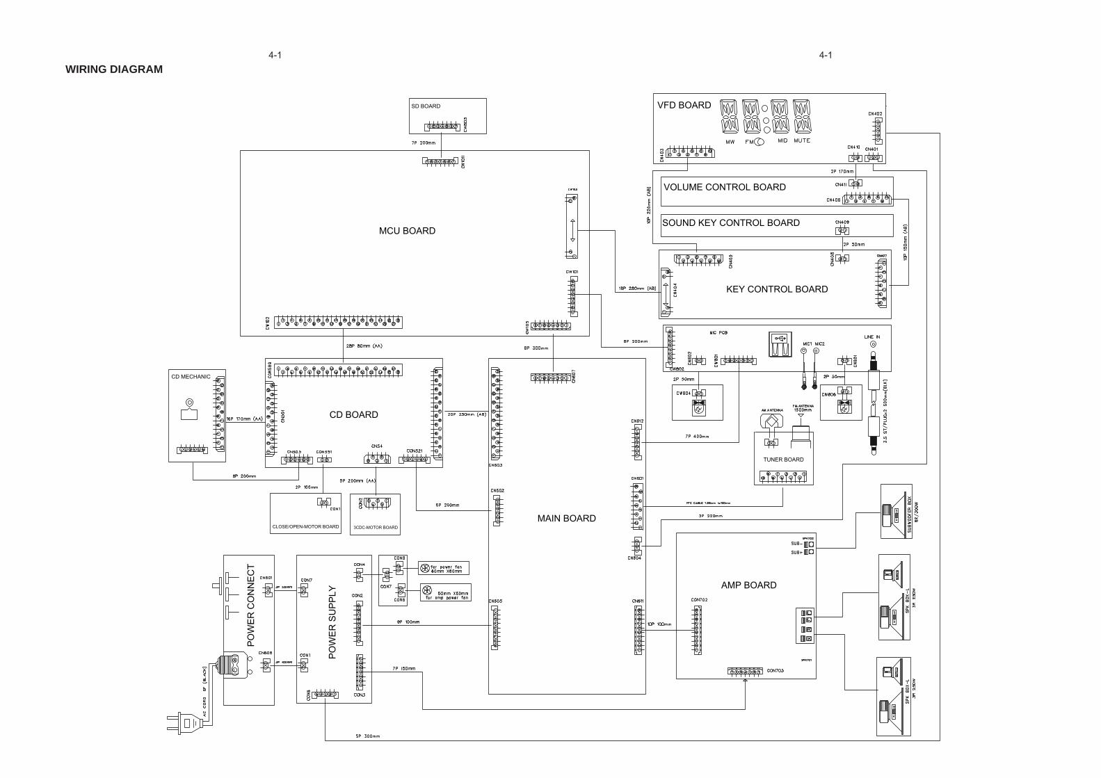
WIRING DIAGRAM4-1 4-1

CIRCUIT DIAGRAM - MAIN BOARD6-1 6-1
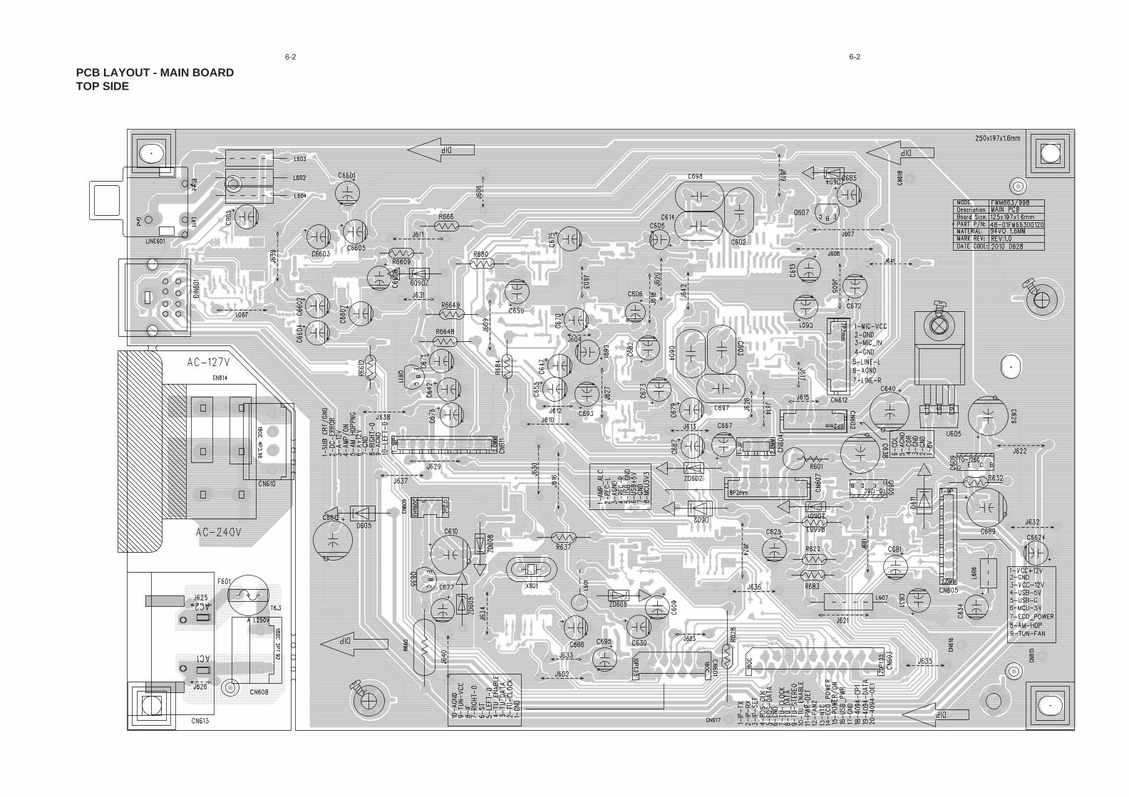
PCB LAYOUT - MAIN BOARDTOP SIDE
6-2 6-2

PCB LAYOUT - MAIN BOARDBOTTOM SIDE
6-3 6-3
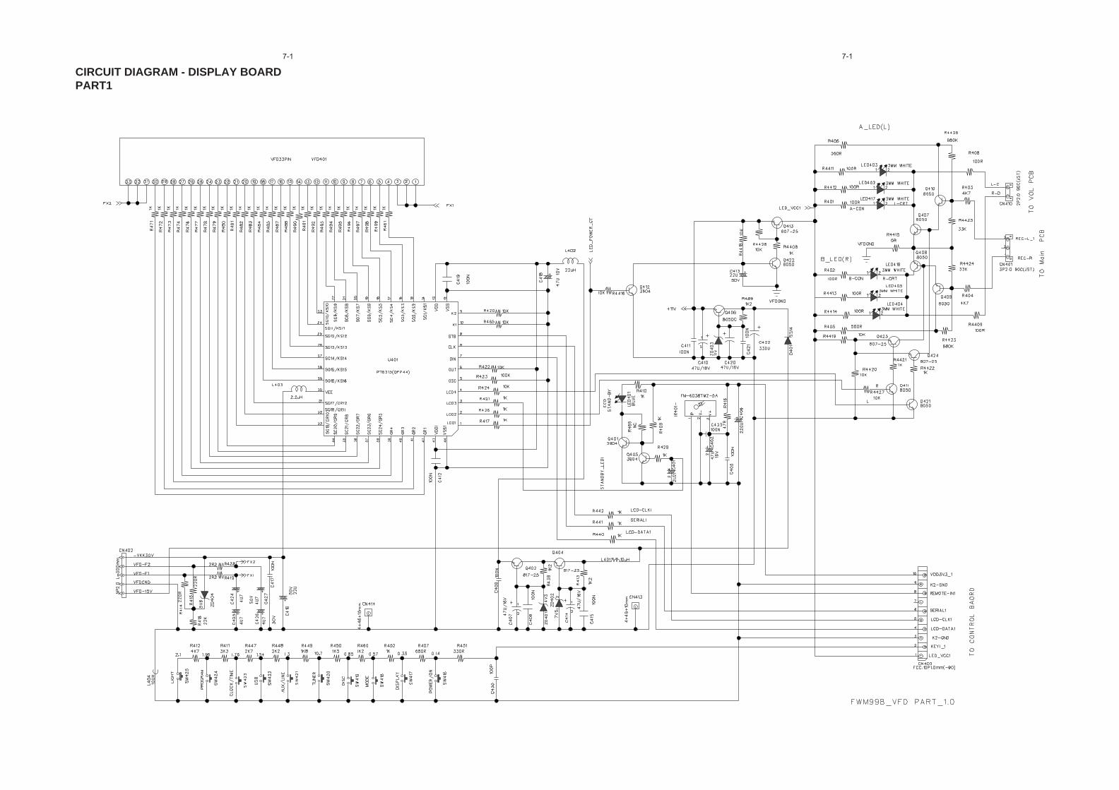
CIRCUIT DIAGRAM - DISPLAY BOARDPART1
7-1 7-1
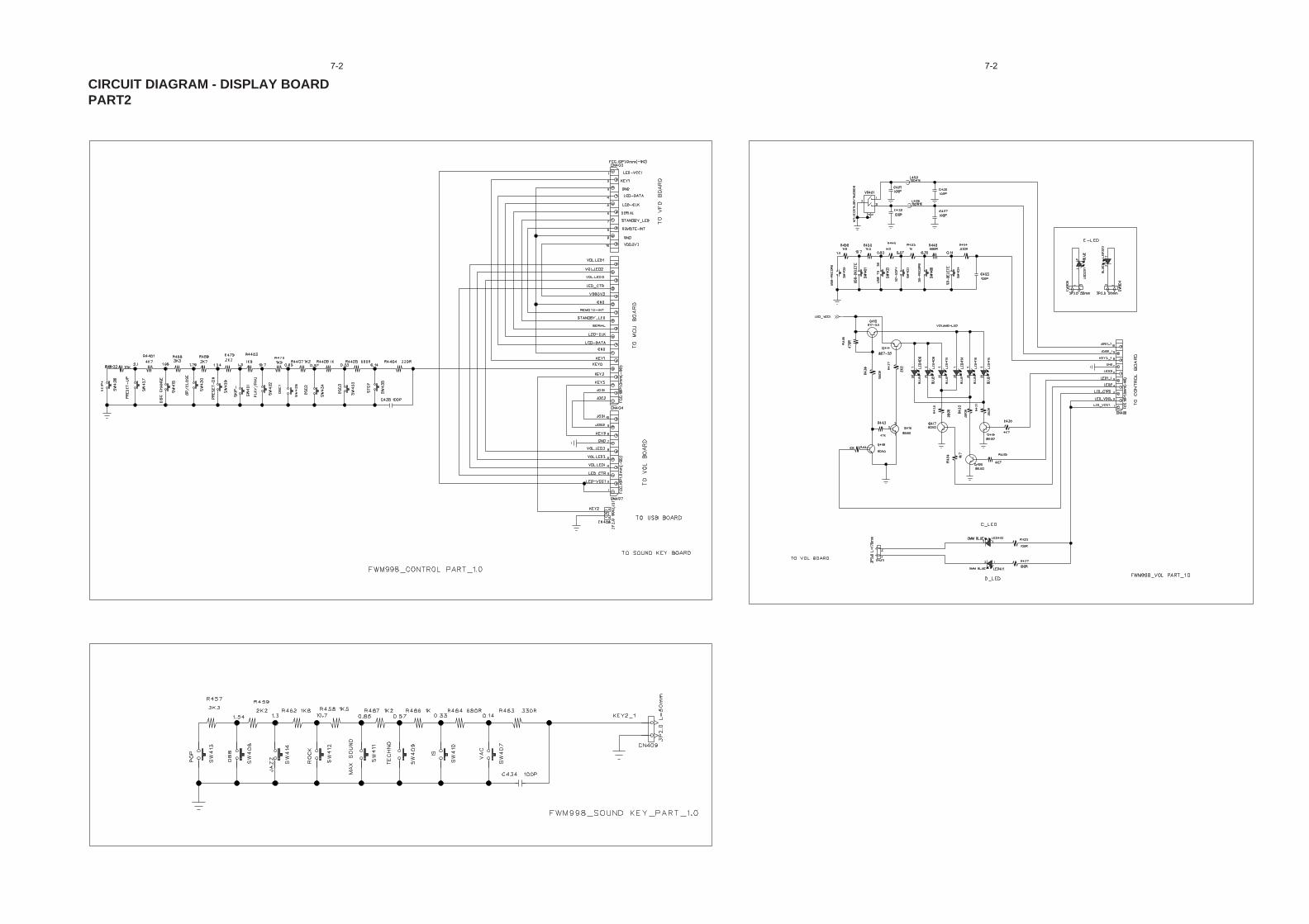
CIRCUIT DIAGRAM - DISPLAY BOARDPART2
7-2 7-2
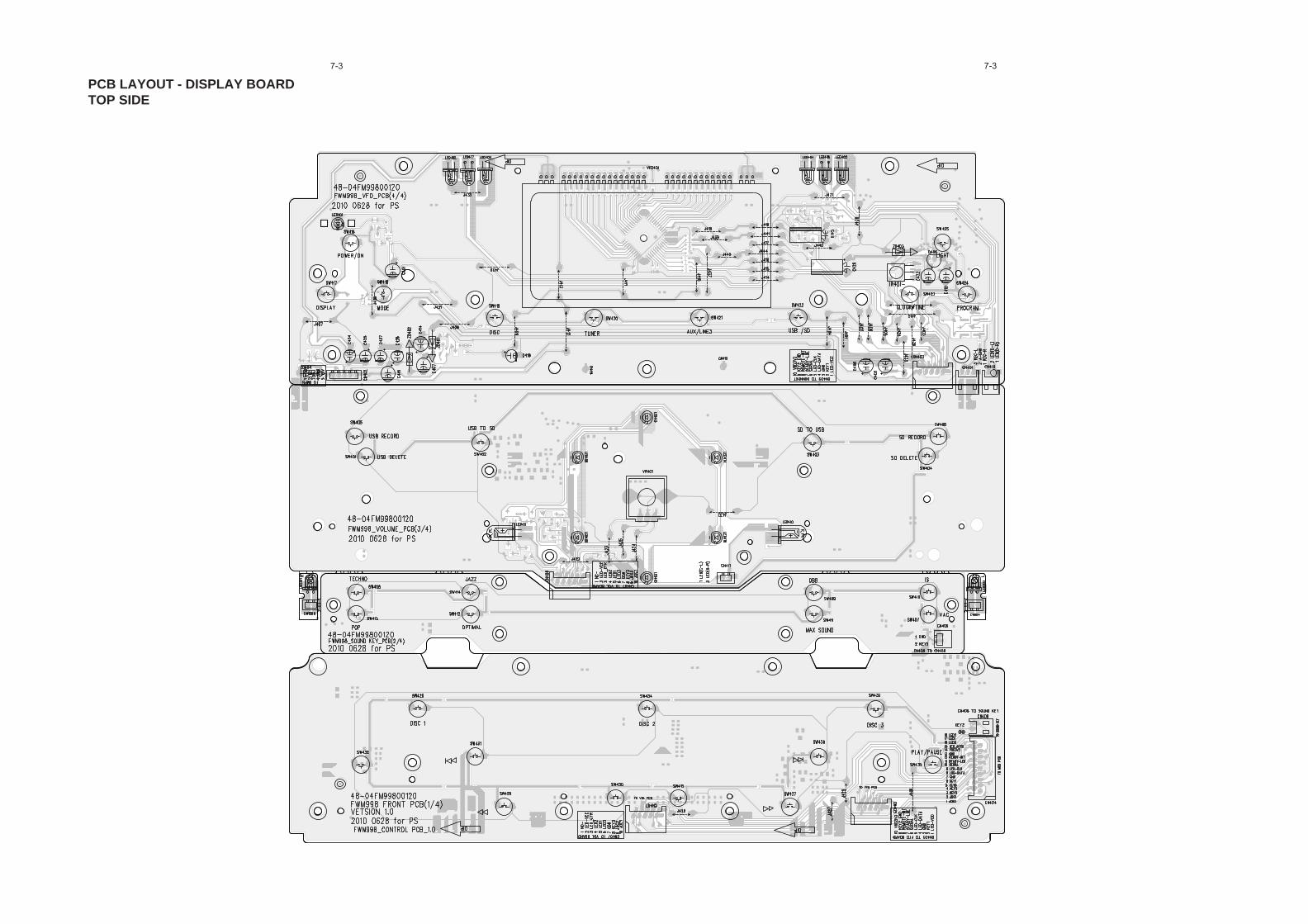
PCB LAYOUT - DISPLAY BOARDTOP SIDE
7-3 7-3

PCB LAYOUT - DISPLAY BOARDBOTTOM SIDE
7-4 7-4

CIRCUIT DIAGRAM - USB/SD BOARD8-1 8-1

PCB LAYOUT - USB BOARD
PCB LAYOUT - SD BOARD
8-2 8-2
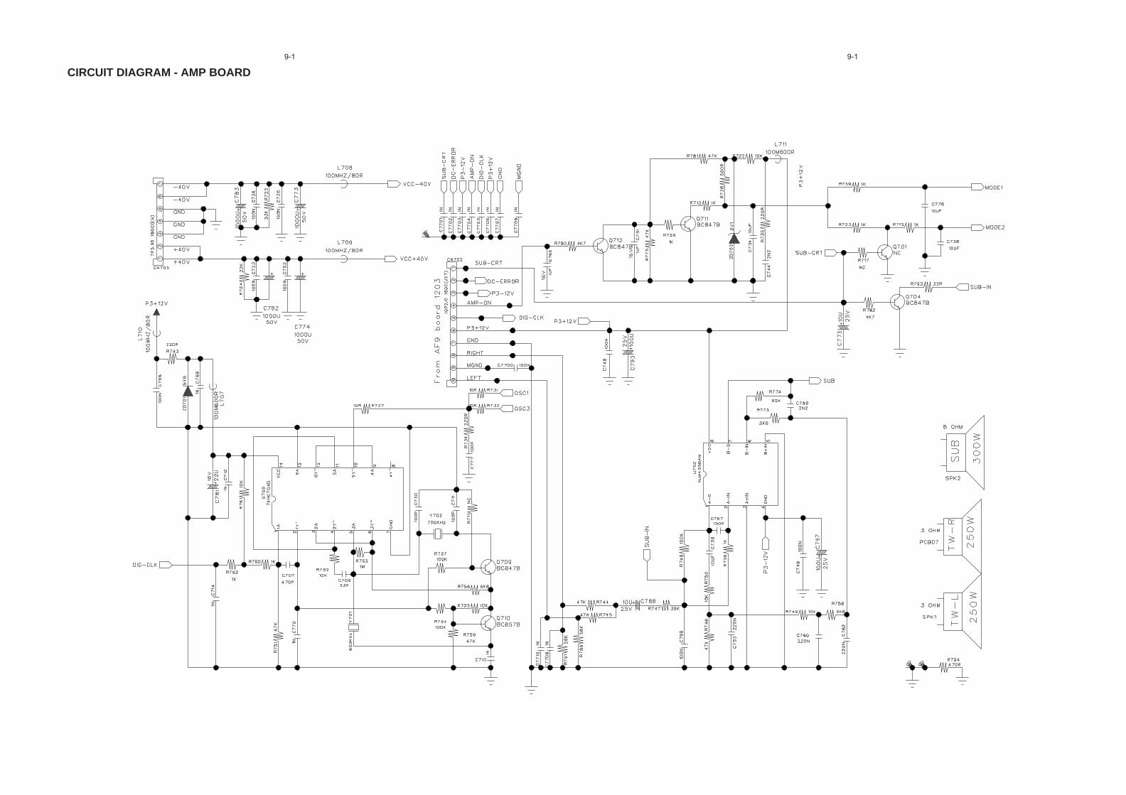
CIRCUIT DIAGRAM - AMP BOARD9-1 9-1

CIRCUIT DIAGRAM - AMP BOARDPART2
9-2 9-2
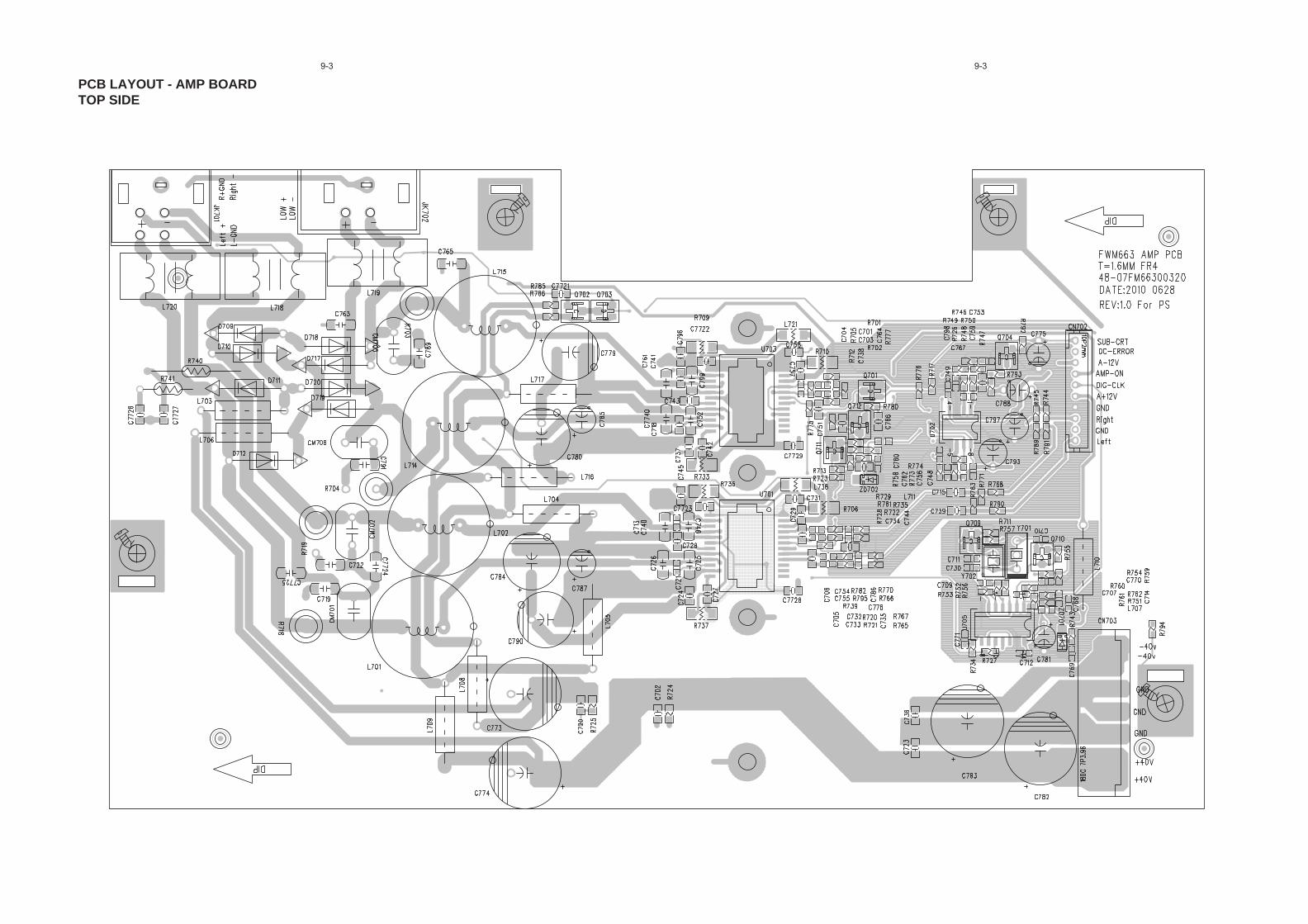
PCB LAYOUT - AMP BOARDTOP SIDE
9-3 9-3
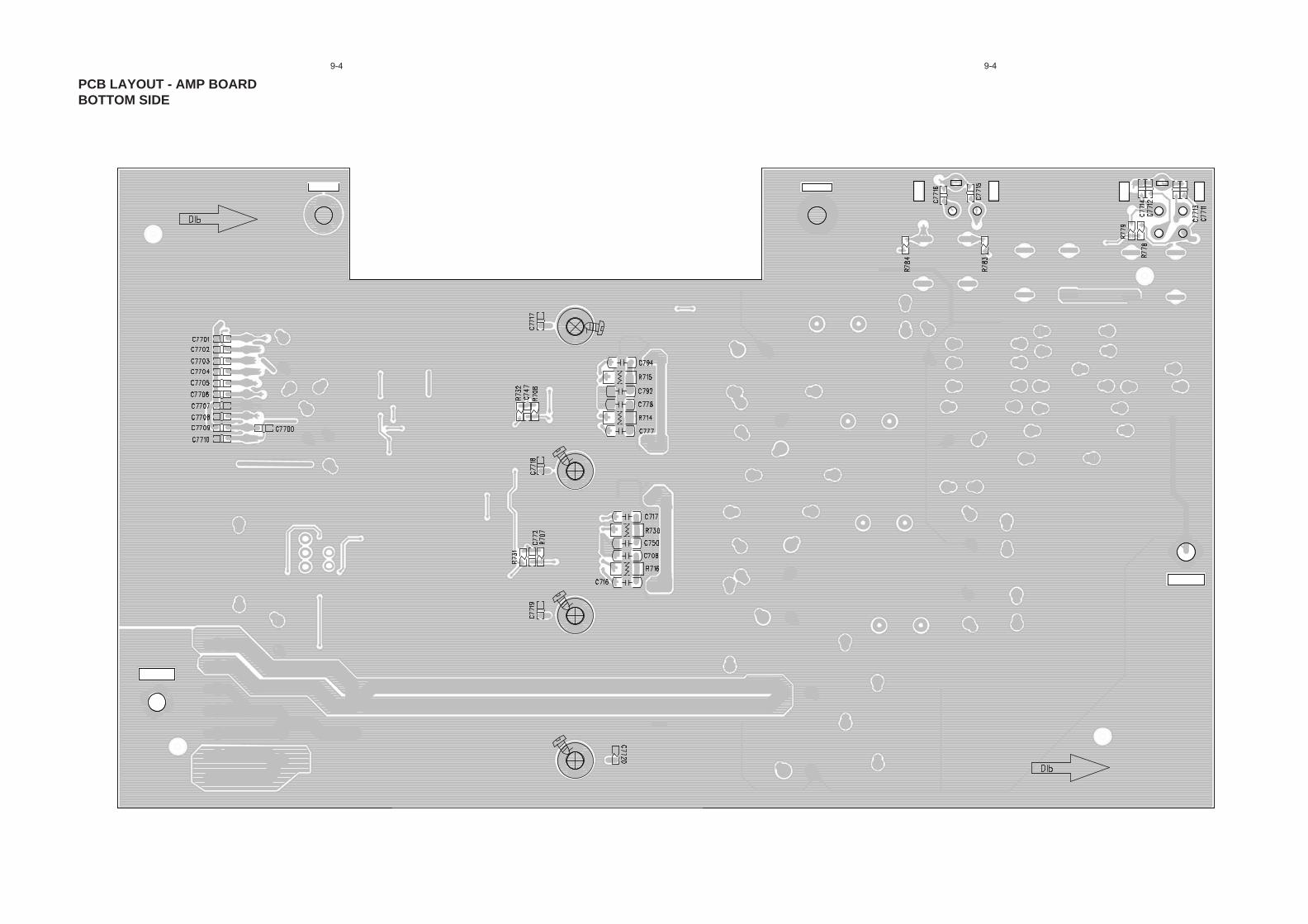
PCB LAYOUT - AMP BOARDBOTTOM SIDE
9-4 9-4
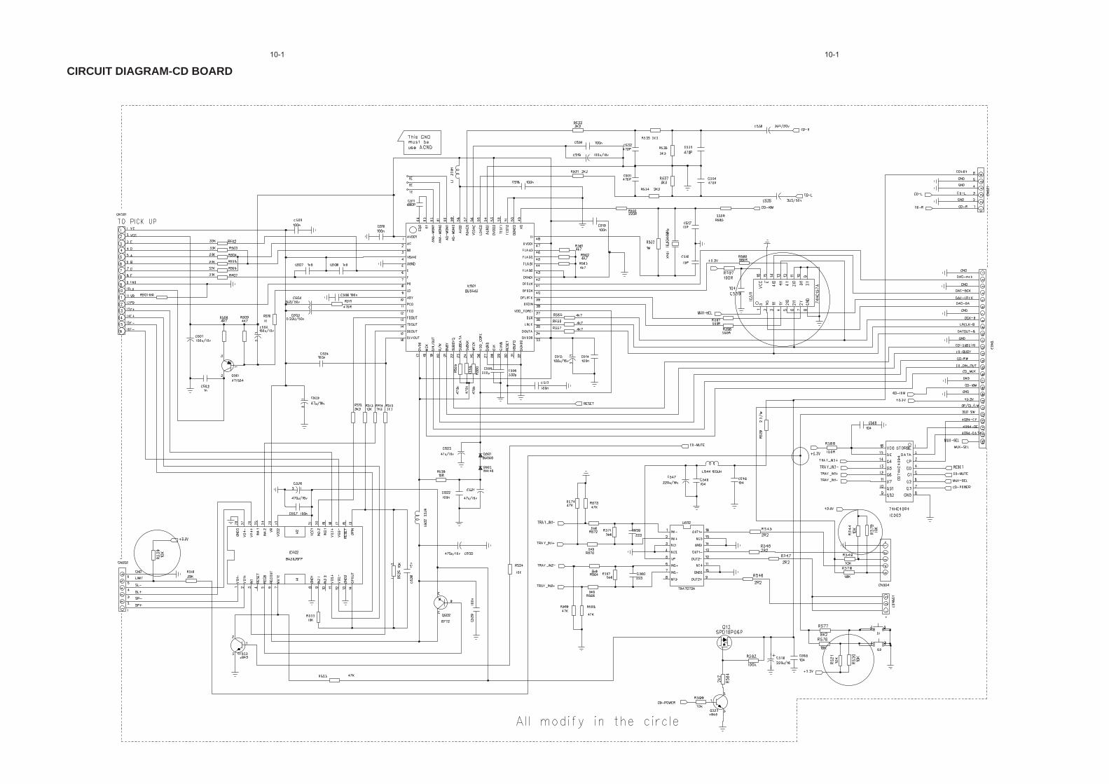
CIRCUIT DIAGRAM-CD BOARD10-110-1

LAYOUT DIAGRAM-CD BOARDTOP SIDE
10-2 10-2

LAYOUT DIAGRAM-CD BOARDBOTTOM SIDE
10-3 10-3

CIRCUIT DIAGRAM - MCU BOARD11-1 11-1
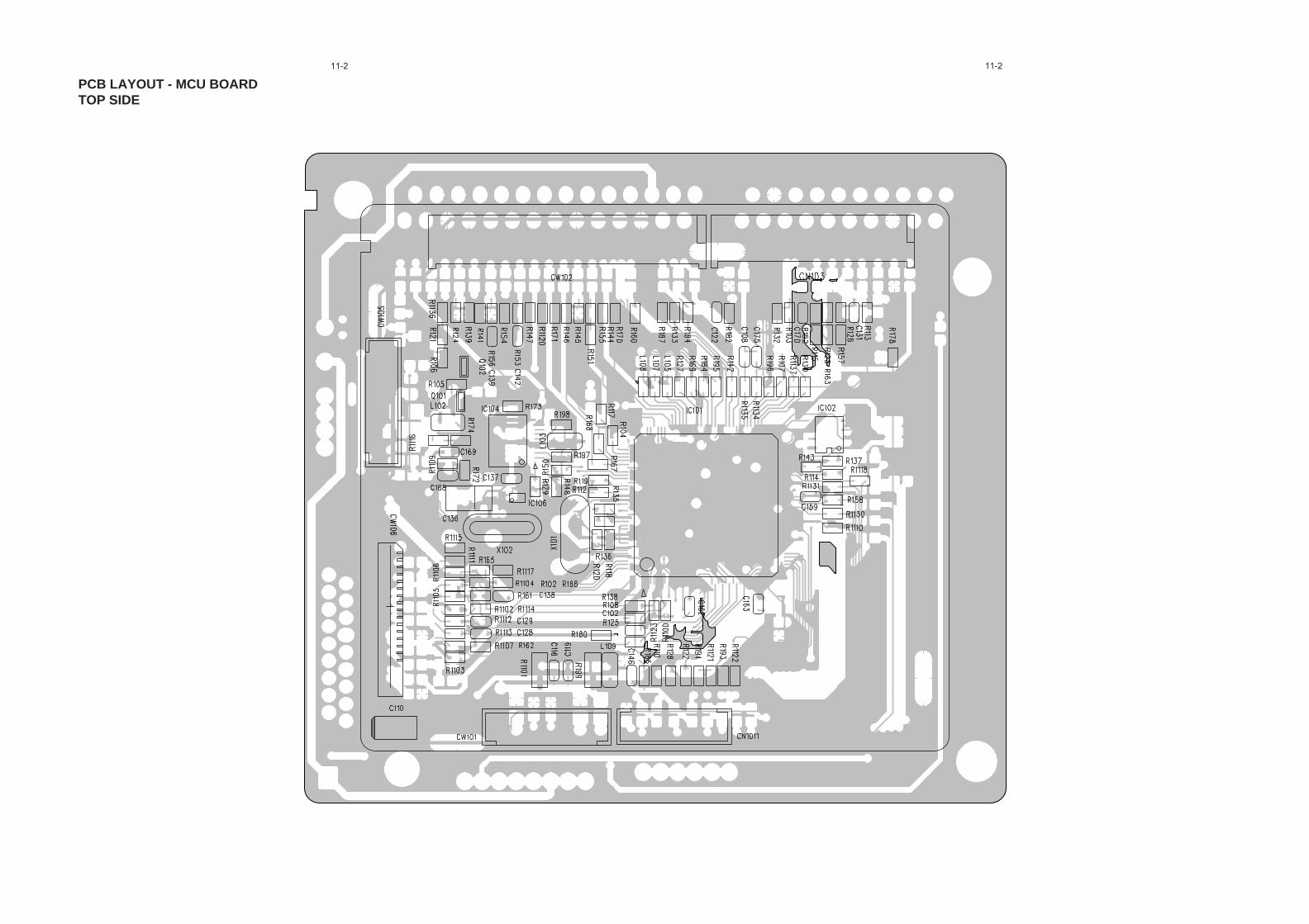
PCB LAYOUT - MCU BOARDTOP SIDE
11-2 11-2

PCB LAYOUT - MCU BOARDBOTTOM SIDE
11-3 11-3
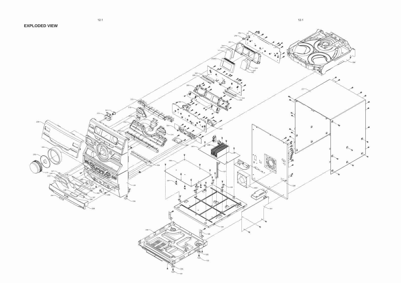
EXPLODED VIEW12-1 12-1