8 Professional Jointer - Mike's Tools
28
INSTRUCTION MANUAL 8" Professional Jointer (Model 37-380) PART NO. 909568 - 07-10-03 Copyright © 2003 Delta Machinery To learn more about DELTA MACHINERY visit our website at: www.deltamachinery.com. For Parts, Service, Warranty or other Assistance, please call 1-800-223-7278 (In Canada call 1-800-463-3582).
Transcript of 8 Professional Jointer - Mike's Tools

INS
TRU
CTIO
NM
AN
UA
L8" Professional Jointer
(Model 37-380)
PART NO. 909568 - 07-10-03Copyright © 2003 Delta Machinery
To learn more about DELTA MACHINERY visit our website at: www.deltamachinery.com.
For Parts, Service, Warranty or other Assistance,
please call 1-800-223-7278 (In Canada call 1-800-463-3582).

2
Indicates an imminently hazardous situation which, if not avoided, will result in death or serious injury.
Indicates a potentially hazardous situation which, if not avoided, could result in death or serious injury.
Indicates a potentially hazardous situation which, if not avoided, may result in minor or moderate injury.
Used without the safety alert symbol indicates potentially hazardous situation which, if not avoided, mayresult in property damage.
This manual contains information that is important for you to know and understand. This information relates to protect-ing YOUR SAFETY and PREVENTING EQUIPMENT PROBLEMS. To help you recognize this information, we use thesymbols to the right. Please read the manual and pay attention to these sections.
SAFETY GUIDELINES - DEFINITIONS
SOME DUST CREATED BY POWER SANDING, SAWING, GRINDING, DRILLING, AND OTHERCONSTRUCTION ACTIVITIES contains chemicals known to cause cancer, birth defects or other reproductive harm.Some examples of these chemicals are:· lead from lead-based paints,· crystalline silica from bricks and cement and other masonry products, and· arsenic and chromium from chemically-treated lumber. Your risk from these exposures varies, depending on how often you do this type of work. To reduce your exposure tothese chemicals: work in a well ventilated area, and work with approved safety equipment, always wear MSHA/NIOSHapproved, properly fitting face mask or respirator when using such tools.
GENERAL SAFETY RULES
READ AND UNDERSTAND ALL WARNINGS AND OPERATING INSTRUCTIONS BEFOREUSING THIS EQUIPMENT. Failure to follow all instructions listed below, may result in electric shock,fire, and/or serious personal injury or property damage.
IMPORTANT SAFETY INSTRUCTIONS
Woodworking can be dangerous if safe and proper operating procedures are not followed. As with all machinery, thereare certain hazards involved with the operation of the product. Using the machine with respect and caution willconsiderably lessen the possibility of personal injury. However, if normal safety precautions are overlooked or ignored,personal injury to the operator may result. Safety equipment such as guards, push sticks, hold-downs, featherboards,goggles, dust masks and hearing protection can reduce your potential for injury. But even the best guard won’t makeup for poor judgment, carelessness or inattention. Always use common sense and exercise caution in the workshop.If a procedure feels dangerous, don’t try it. Figure out an alternative procedure that feels safer. REMEMBER: Yourpersonal safety is your responsibility. For additional information please visit our website www.deltamachinery.com.
This machine was designed for certain applications only. Delta Machinery strongly recommends that thismachine not be modified and/or used for any application other than that for which it was designed. If you have anyquestions relative to a particular application, DO NOT use the machine until you have first contacted Delta to determineif it can or should be performed on the product.
Technical Service ManagerDelta Machinery4825 Highway 45 NorthJackson, TN 38305
(IN CANADA: 505 SOUTHGATE DRIVE, GUELPH, ONTARIO N1H 6M7)

3
FAILURE TO FOLLOW THESE RULES MAY RESULT IN SERIOUS PERSONAL INJURY.
1. FOR YOUR OWN SAFETY, READ THE INSTRUC-TION MANUAL BEFORE OPERATING THEMACHINE. Learning the machine’s application,limitations, and specific hazards will greatlyminimize the possibility of accidents and injury.
2. USE CERTIFIED SAFETY EQUIPMENT. Eyeprotection equipment should comply with ANSIZ87.1 standards, hearing equipment shouldcomply with ANSI S3.19 standards, and dust maskprotection should comply with MSHA/NIOSHcertified respirator standards. Splinters, air-bornedebris, and dust can cause irritation, injury, and/orillness.
3. DRESS PROPERLY. Do not wear tie, gloves, orloose clothing. Remove watch, rings, and otherjewelry. Roll up your sleeves. Clothing or jewelrycaught in moving parts can cause injury.
4. DO NOT USE THE MACHINE IN A DANGEROUSENVIRONMENT. The use of power tools in dampor wet locations or in rain can cause shock orelectrocution. Keep your work area well-lit toprevent tripping or placing arms, hands, andfingers in danger.
5. MAINTAIN ALL TOOLS AND MACHINES IN PEAKCONDITION. Keep tools sharp and clean for best andsafest performance. Follow instructions for lubricatingand changing accessories. Poorly maintained tools andmachines can further damage the tool or machine and/orcause injury.
6. CHECK FOR DAMAGED PARTS. Before using themachine, check for any damaged parts. Check foralignment of moving parts, binding of movingparts, breakage of parts, and any other conditionsthat may affect its operation. A guard or any otherpart that is damaged should be properly repairedor replaced. Damaged parts can cause furtherdamage to the machine and/or injury.
7. KEEP THE WORK AREA CLEAN. Cluttered areas andbenches invite accidents.
8. KEEP CHILDREN AND VISITORS AWAY. Your shop isa potentially dangerous environment. Children and visitorscan be injured.
9. REDUCE THE RISK OF UNINTENTIONAL STARTING.Make sure that the switch is in the “OFF” positionbefore plugging in the power cord. In the event ofa power failure, move the switch to the “OFF”position. An accidental start-up can cause injury.
10. USE THE GUARDS. Check to see that all guardsare in place, secured, and working correctly toprevent injury.
11. REMOVE ADJUSTING KEYS AND WRENCHESBEFORE STARTING THE MACHINE. Tools, scrappieces, and other debris can be thrown at highspeed, causing injury.
12. USE THE RIGHT MACHINE. Don’t force amachine or an attachment to do a job for which itwas not designed. Damage to the machine and/orinjury may result.
13. USE RECOMMENDED ACCESSORIES. The useof accessories and attachments not recom-mended by Delta may cause damage to themachine or injury to the user.
14. USE THE PROPER EXTENSION CORD. Makesure your extension cord is in good condition.When using an extension cord, be sure to use oneheavy enough to carry the current your product willdraw. An undersized cord will cause a drop in linevoltage, resulting in loss of power and overheating.See the Extension Cord Chart for the correct sizedepending on the cord length and nameplateampere rating. If in doubt, use the next heaviergauge. The smaller the gauge number, the heavierthe cord.
15. SECURE THE WORKPIECE. Use clamps or a vise tohold the workpiece when practical. Loss of controlof a workpiece can cause injury.
16. FEED THE WORKPIECE AGAINST THE DIRECTIONOF THE ROTATION OF THE BLADE, CUTTER, ORABRASIVE SURFACE. Feeding it from the otherdirection will cause the workpiece to be thrown outat high speed.
17. DON’T FORCE THE WORKPIECE ON THEMACHINE. Damage to the machine and/or injurymay result.
18. DON’T OVERREACH. Loss of balance can makeyou fall into a working machine, causing injury.
19. NEVER STAND ON THE MACHINE. Injury could occur ifthe tool tips, or if you accidentally contact the cutting tool.
20. NEVER LEAVE THE MACHINE RUNNING UNATTEN-DED. TURN THE POWER OFF. Don’t leave the machineuntil it comes to a complete stop. A child or visitor couldbe injured.
21. TURN THE MACHINE “OFF”, AND DISCONNECT THEMACHINE FROM THE POWER SOURCE beforeinstalling or removing accessories, before adjustingor changing set-ups, or when making repairs. Anaccidental start-up can cause injury.
22. MAKE YOUR WORKSHOP CHILDPROOF WITHPADLOCKS, MASTER SWITCHES, OR BYREMOVING STARTER KEYS. The accidentalstart-up of a machine by a child or visitor couldcause injury.
23. STAY ALERT, WATCH WHAT YOU ARE DOING,AND USE COMMON SENSE. DO NOT USE THEMACHINE WHEN YOU ARE TIRED OR UNDERTHE INFLUENCE OF DRUGS, ALCOHOL, ORMEDICATION. A moment of inattention whileoperating power tools may result in injury.
24. THE DUST GENERATED by certain woods andwood products can be injurious to your health.Always operate machinery in well-ventilated areas,and provide for proper dust removal. Use wooddust collection systems whenever possible.

4
ADDITIONAL SAFETY RULESFOR JOINTERS
1. DO NOT OPERATE THIS MACHINE until it iscompletely assembled and installed according tothe instructions. A machine incorrectly assembledcan cause serious injury.
2. OBTAIN ADVICE from your supervisor, instructor,or another qualified person if you are notthoroughly familiar with the operation of thismachine. Knowledge is safety.
3. FOLLOW ALL WIRING CODES andrecommended electrical connections to preventshock or electrocution.
4. KEEP KNIVES SHARP and free from rust andpitch. Dull or rusted knives work harder and cancause kickback.
5. TIGHTEN THE INFEED/OUTFEED TABLES beforestarting the machine. Loss of control of the work-piece can cause serious injury.
6. PROPERLY SECURE THE BLADES IN THECUTTERHEAD before turning the power “ON”.Loose blades may be thrown out at high speeds.
7. NEVER TURN THE MACHINE “ON” before clearingthe table of all objects (tools, scraps of wood, etc.).Flying debris can cause serious injury.
8. NEVER TURN THE MACHINE “ON” with theworkpiece contacting the cutterhead. Kickbackcan occur.
9. AVOID AWKWARD OPERATIONS AND HANDPOSITIONS. A sudden slip could cause a hand tomove into the cutterhead.
10. KEEP ARMS, HANDS, AND FINGERS away fromthe cutterhead to prevent severe injury.
11. NEVER MAKE CUTS deeper than 1/8" (3.2mm) toprevent kickback.
12. NEVER JOINT OR PLANE A WORKPIECE that isshorter than 10" (254mm), narrower than 3/4"(19.0MM), or less than 1/2" (12.7mm) thick.Jointing smaller workpieces can place your handin the cutterhead causing severe injury.
13. USE HOLD-DOWN/PUSH BLOCKS for jointing orplaning any workpiece lower than the fence.Jointing or planing small workpieces can result inkickback and severe injury.
14. HOLD THE WORKPIECE FIRMLY against thetable and fence. Loss of control of the workpiececan cause kickback and result in serious injury.
15. NEVER PERFORM “FREE-HAND” OPERATIONS.Use the fence to position and guide theworkpiece. Loss of control of the workpiece cancause serious injury.
16. DO NOT attempt to perform an abnormal or little-used operation without study and the use ofadequate hold-down/push blocks, jigs, fixtures,stops, etc.
17. DO NOT FEED A WORKPIECE into the outfeedend of the machine.The workpiece will be thrownout of the opposite end at high speeds.
18. DO NOT FEED A WORKPIECE that is warped,contains knots, or is embedded with foreignobjects (nails, staples, etc.) to prevent kickback.
19. MAINTAIN THE PROPER RELATIONSHIP OFINFEED AND OUTFEED TABLE SURFACES andcutterhead knife path. Loss of control of the work-piece can cause serious injury.
20. PROPERLY SUPPORT LONG OR WIDEWORKPIECES. Loss of control of the workpiece cancause injury.
21. NEVER PERFORM LAYOUT, ASSEMBLY, OR SET-UP WORK on the table/work area when themachine is running. A sudden slip could cause ahand to move into the cutterhead. Severe injurycan result.
22. TURN THE MACHINE “OFF”, disconnect themachine from the power source, and clean thetable/work area before leaving the machine.LOCK THE SWITCH IN THE “OFF” POSITION toprevent unauthorized use. Someone else mightaccidentally start the machine and cause injury tothemselves.
23. ADDITIONAL INFORMATION regarding the safeand proper operation of power tools (i.e. a safetyvideo) is available from the Power Tool Institute,1300 Sumner Avenue, Cleveland, OH 44115-2851(www.powertoolinstitute.com). Information is alsoavailable from the National Safety Council, 1121Spring Lake Drive, Itasca, IL 60143-3201. Pleaserefer to the American National Standards InstituteANSI 01.1 Safety Requirements for WoodworkingMachines and the U.S. Department of LaborOSHA 1910.213 Regulations.
FAILURE TO FOLLOW THESE RULES MAY RESULT IN SERIOUS INJURY.
SAVE THESE INSTRUCTIONS. Refer to them often and use them to instruct others.
5
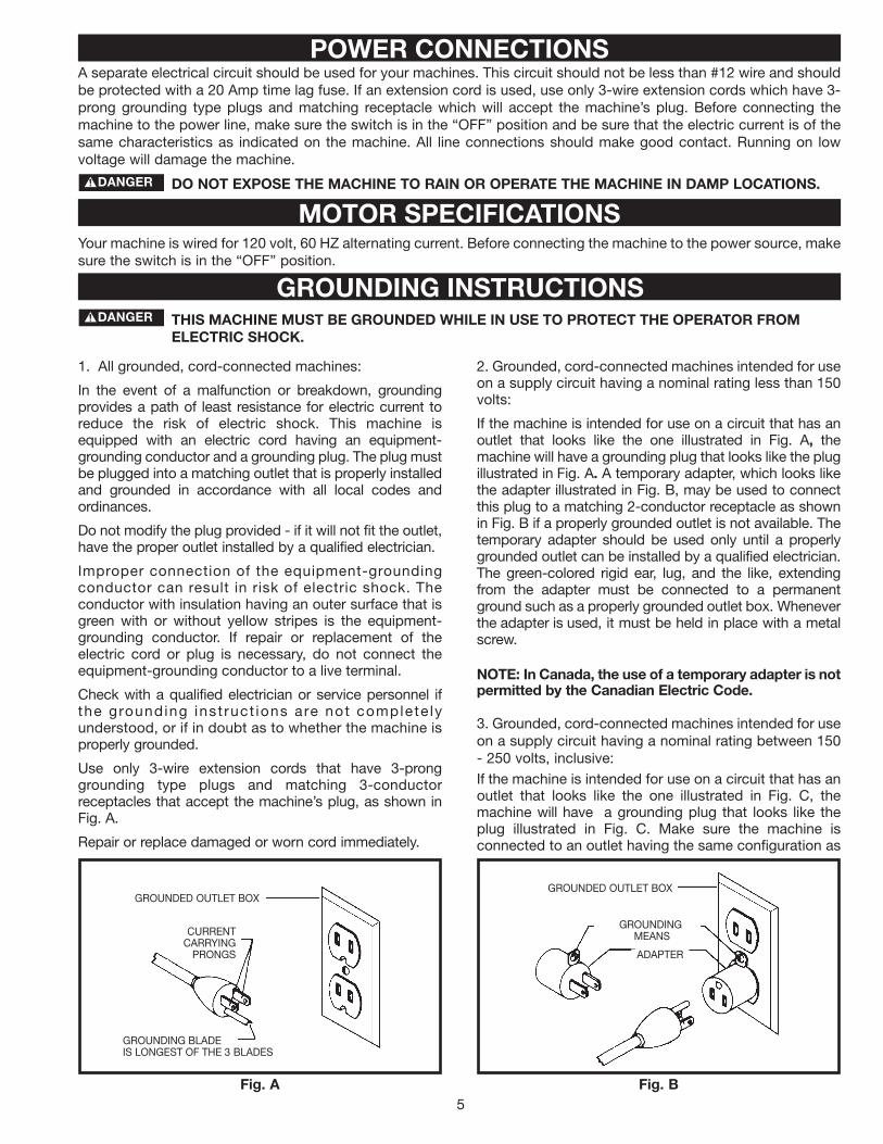
A separate electrical circuit should be used for your machines. This circuit should not be less than #12 wire and shouldbe protected with a 20 Amp time lag fuse. If an extension cord is used, use only 3-wire extension cords which have 3-prong grounding type plugs and matching receptacle which will accept the machine’s plug. Before connecting themachine to the power line, make sure the switch is in the “OFF” position and be sure that the electric current is of thesame characteristics as indicated on the machine. All line connections should make good contact. Running on lowvoltage will damage the machine.
DO NOT EXPOSE THE MACHINE TO RAIN OR OPERATE THE MACHINE IN DAMP LOCATIONS.
Your machine is wired for 120 volt, 60 HZ alternating current. Before connecting the machine to the power source, makesure the switch is in the “OFF” position.
THIS MACHINE MUST BE GROUNDED WHILE IN USE TO PROTECT THE OPERATOR FROMELECTRIC SHOCK.
MOTOR SPECIFICATIONS
GROUNDED OUTLET BOX
CURRENTCARRYING
PRONGS
GROUNDING BLADEIS LONGEST OF THE 3 BLADES
GROUNDED OUTLET BOX
GROUNDINGMEANS
ADAPTER
2. Grounded, cord-connected machines intended for useon a supply circuit having a nominal rating less than 150volts:
If the machine is intended for use on a circuit that has anoutlet that looks like the one illustrated in Fig. A, themachine will have a grounding plug that looks like the plugillustrated in Fig. A. A temporary adapter, which looks likethe adapter illustrated in Fig. B, may be used to connectthis plug to a matching 2-conductor receptacle as shownin Fig. B if a properly grounded outlet is not available. Thetemporary adapter should be used only until a properlygrounded outlet can be installed by a qualified electrician.The green-colored rigid ear, lug, and the like, extendingfrom the adapter must be connected to a permanentground such as a properly grounded outlet box. Wheneverthe adapter is used, it must be held in place with a metalscrew.
NOTE: In Canada, the use of a temporary adapter is notpermitted by the Canadian Electric Code.
3. Grounded, cord-connected machines intended for useon a supply circuit having a nominal rating between 150- 250 volts, inclusive:If the machine is intended for use on a circuit that has anoutlet that looks like the one illustrated in Fig. C, themachine will have a grounding plug that looks like theplug illustrated in Fig. C. Make sure the machine isconnected to an outlet having the same configuration as
1. All grounded, cord-connected machines:
In the event of a malfunction or breakdown, groundingprovides a path of least resistance for electric current toreduce the risk of electric shock. This machine isequipped with an electric cord having an equipment-grounding conductor and a grounding plug. The plug mustbe plugged into a matching outlet that is properly installedand grounded in accordance with all local codes andordinances.
Do not modify the plug provided - if it will not fit the outlet,have the proper outlet installed by a qualified electrician.
Improper connection of the equipment-groundingconductor can result in risk of electric shock. Theconductor with insulation having an outer surface that isgreen with or without yellow stripes is the equipment-grounding conductor. If repair or replacement of theelectric cord or plug is necessary, do not connect theequipment-grounding conductor to a live terminal.
Check with a qualified electrician or service personnel ifthe grounding inst ruct ions are not complete lyunderstood, or if in doubt as to whether the machine isproperly grounded.
Use only 3-wire extension cords that have 3-pronggrounding type plugs and matching 3-conductorreceptacles that accept the machine’s plug, as shown inFig. A.
Repair or replace damaged or worn cord immediately.
POWER CONNECTIONS
GROUNDING INSTRUCTIONS
Fig. A Fig. B

6
Use proper extension cords. Make sure your extension cord is in good condition and is a 3-wireextension cord which has a 3-prong grounding type plug and matching receptacle which will accept the machine’splug. When using an extension cord, be sure to use one heavy enough to carry the current of the machine. Anundersized cord will cause a drop in line voltage, resulting in loss of power and overheating. Fig. D, shows the correctgauge to use depending on the cord length. If in doubt, use the next heavier gauge. The smaller the gauge number,the heavier the cord.
EXTENSION CORDS
FOREWORDDelta Model 37-380 is a 8" Professional Jointer with a cutting capacity of 8" (203mm) width, 1/8" depth (3mm max.) and1/2" (13mm) rabbeting. Unit includes; heavy-duty 1-1/2 hp, 120/240 volt induction motor, stand, dust chute, fence, three-knife cutterhead, cutterhead guard, and push blocks.
Carefully unpack the machine and all loose items from the shipping container(s). Remove the protective coating fromall unpainted surfaces. This coating may be removed with a soft cloth moistened with kerosene (do not use acetone,gasoline or lacquer thinner for this purpose). After cleaning, cover the unpainted surfaces with a good quality householdfloor paste wax.
NOTICE: THE MANUAL COVER PHOTO ILLUSTRATES THE CURRENTPRODUCTION MODEL. ALL OTHER ILLUSTRATIONS ARE REPRESENTATIVE
ONLY AND MAY NOT DEPICT THE ACTUAL COLOR, LABELING ORACCESSORIES AND MAY BE INTENDED TO ILLUSTRATE TECHNIQUE ONLY.
Fig. D Fig. D
MINIMUM GAUGE EXTENSION CORDRECOMMENDED SIZES FOR USE WITH STATIONARY ELECTRIC MACHINES
Ampere Total Length Gauge ofRating Volts of Cord in Feet Extension Cord
0-6 120 up to 25 18 AWG0-6 120 25-50 16 AWG0-6 120 50-100 16 AWG0-6 120 100-150 14 AWG
6-10 120 up to 25 18 AWG6-10 120 25-50 16 AWG6-10 120 50-100 14 AWG6-10 120 100-150 12 AWG
10-12 120 up to 25 16 AWG10-12 120 25-50 16 AWG10-12 120 50-100 14 AWG10-12 120 100-150 12 AWG
12-16 120 up to 25 14 AWG12-16 120 25-50 12 AWG12-16 120 GREATER THAN 50 FEET NOT RECOMMENDED
MINIMUM GAUGE EXTENSION CORDRECOMMENDED SIZES FOR USE WITH STATIONARY ELECTRIC MACHINES
Ampere Total Length Gauge ofRating Volts of Cord in Feet Extension Cord
0-6 240 up to 50 18 AWG0-6 240 50-100 16 AWG0-6 240 100-200 16 AWG0-6 240 200-300 14 AWG
6-10 240 up to 50 18 AWG6-10 240 50-100 16 AWG6-10 240 100-200 14 AWG6-10 240 200-300 12 AWG
10-12 240 up to 50 16 AWG10-12 240 50-100 16 AWG10-12 240 100-200 14 AWG10-12 240 200-300 12 AWG
12-16 240 up to 50 14 AWG12-16 240 50-100 12 AWG12-16 240 GREATER THAN 100 FEET NOT RECOMMENDED
Fig. C
GROUNDED OUTLET BOX
CURRENTCARRYING
PRONGS
GROUNDING BLADEIS LONGEST OF THE 3 BLADES
the plug. No adapter is available or should be used withthis machine. If the machine must be re-connected foruse on a different type of electric circuit, the re-connection should be made by qualified servicepersonnel; and after re-connection, the machine shouldcomply with all local codes and ordinances.
I N A L L C A S E S , M A K E C E RTA I NTHE RECEPTACLE IN QUESTION IS PROPERLYGROUNDED. IF YOU ARE NOT SURE HAVE AQ U A L I F I E D E L E C T R I C I A N C H E C K T H ERECEPTACLE.
OPERATING INSTRUCTIONS
UNPACKING AND CLEANING

7
JOINTER PARTS
Fig. 2
1. Jointer
2. Fence Carriage Assembly
3. Cutterhead Pulley Guard/Carriage Mounting Bracket
4. Table Raising Handle
5. Switch Mounting Bracket
6. Cutterhead Guard
7. Fence Tilting Handles (2)
8. Fence
9. Push Blocks (2)
10. 6mm Hex Wrench
11. 4mm Hex Wrench
12. 3mm Hex Wrench
13. 2.5mm Hex Wrench
14. 12-14mm Open End Wrench
15. 8-10mm Open End Wrench
1
2
34
5
6 78
9
10 11
12
13
14 15
8
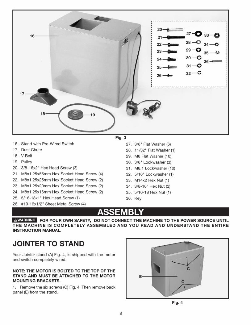
Fig. 3
16. Stand with Pre-Wired Switch
17. Dust Chute
18. V-Belt
19. Pulley
20. 3/8-16x2" Hex Head Screw (3)
21. M8x1.25x55mm Hex Socket Head Screw (4)
22. M8x1.25x25mm Hex Socket Head Screw (2)
23. M8x1.25x20mm Hex Socket Head Screw (2)
24. M8x1.25x16mm Hex Socket Head Screw (2)
25. 5/16-18x1" Hex Head Screw (1)
26. #10-16x1/2" Sheet Metal Screw (4)
27. 3/8" Flat Washer (6)
28. 11/32" Flat Washer (1)
29. M8 Flat Washer (10)
30. 3/8" Lockwasher (3)
31. M8.1 Lockwasher (10)
32. 5/16" Lockwasher (1)
33. M14x2 Hex Nut (1)
34. 3/8-16" Hex Nut (3)
35. 5/16-18 Hex Nut (1)
36. Key
16
17
18 19
20
21
22
23
24
25
26
27
28
29
30
31
32
34
35
36
ASSEMBLYFOR YOUR OWN SAFETY, DO NOT CONNECT THE MACHINE TO THE POWER SOURCE UNTIL
THE MACHINE IS COMPLETELY ASSEMBLED AND YOU READ AND UNDERSTAND THE ENTIREINSTRUCTION MANUAL.
Fig. 4
JOINTER TO STANDYour Jointer stand (A) Fig. 4, is shipped with the motorand switch completely wired.
NOTE: THE MOTOR IS BOLTED TO THE TOP OF THESTAND AND MUST BE ATTACHED TO THE MOTORMOUNTING BRACKETS.
1. Remove the six screws (C) Fig. 4. Then remove backpanel (E) from the stand.
33
C
CE

9
2. Remove the four bolts that attach the motor (A) Fig.5 to top of the stand. NOTE: SAVE THESE BOLTS ASTHEY WILL BE USED TO ATTACH THE MOTOR TOTHE MOUNTING BRACKETS.
Fig. 5
5. Line up three holes (F) and (L) Fig. 6, on top of standwith three holes located at the bottom of the jointerbase. Place a 3/8" flat washer (H) Fig. 7, on a 3/8-16x2"hex head screw (G), insert the screw through the hole inthe base of the Jointer and hole (F) Fig. 6, in the stand.Place a 3/8" flat washer (H) Fig. 7, 3/8" lockwasher (J),and thread a 3/8-16 hex nut (K) onto the screw andtighten securely. Repeat this process for the remaininghole (F) in the stand and Jointer base. Repeat thisprocess for hole (L) in the stand and Jointer base byinserting the screw up through hole (L) in the stand andthe Jointer base.
Fig. 6
F
L
THE JOINTER IS EXTREMELY HEAVY.HAVE TWO OR MORE PEOPLE LIFT THE MACHINEO N T O T H E S TA N D O R L I F T T H E J O I N T E RMECHANICALLY.
Fig. 7
GH
J
K
Fig. 8
ASSEMBLING INFEED TABLEADJUSTMENT HANDLE1. Thread an M14x2 hex nut (A) Fig. 8, clockwise ontothe end of adjustment handle (B) as far as it will go.
2. Thread handle (B) Fig. 8, into block (C) which islocated under infeed table (D). Tighten hex nut (A) Fig. 8,against block (C).
D BA
C
A
3. Align the holes in the motor mounting plate (B) Fig.5A with the four holes in the two motor mountingbrackets (C). Attach the motor to the motor mountingbrackets with the hardware that was removed in STEP 2.NOTE: MAKE SURE THAT MOTOR SHAFT (D) FIG 5AIS FACING OUT OF THE OPENING IN THE MOTORCABINET AS SHOWN.
4. Turn the stand over so that it is resting on its baseas shown in Fig. 6.
Fig. 5A
B
C
D
10
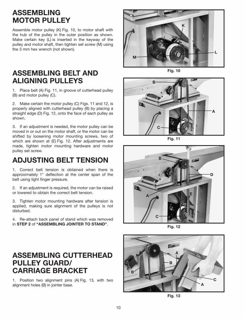
ASSEMBLINGMOTOR PULLEYAssemble motor pulley (K) Fig. 10, to motor shaft withthe hub of the pulley in the outer position as shown.Make certain key (L) is inserted in the keyway of thepulley and motor shaft, then tighten set screw (M) usingthe 3 mm hex wrench (not shown).
Fig. 10
K
LM
ASSEMBLING BELT ANDALIGNING PULLEYS1. Place belt (A) Fig. 11, in groove of cutterhead pulley(B) and motor pulley (C).
2. Make certain the motor pulley (C) Figs. 11 and 12, isproperly aligned with cutterhead pulley (B) by placing astraight edge (D) Fig. 12, onto the face of each pulley asshown.
3. If an adjustment is needed, the motor pulley can bemoved in or out on the motor shaft, or the motor can beshifted by loosening motor mounting screws, two ofwhich are shown at (E) Fig. 12. After adjustments aremade, tighten motor mounting hardware and motorpulley set screw.
Fig. 11
Fig. 12
A
C
B
EA
B
C
D
ADJUSTING BELT TENSION1. Correct belt tension is obtained when there isapproximately 1" deflection at the center span of thebelt using light finger pressure.
2. If an adjustment is required, the motor can be raisedor lowered to obtain the correct belt tension.
3. Tighten motor mounting hardware after tension isapplied, making sure alignment of the pulleys is notdisturbed.
4. Re-attach back panel of stand which was removedin STEP 2 of “ASSEMBLING JOINTER TO STAND”.
Fig. 13
B
B
A
AC
ASSEMBLING CUTTERHEADPULLEY GUARD/CARRIAGE BRACKET1. Position two alignment pins (A) Fig. 13, with twoalignment holes (B) in jointer base.

11
2. Using the supplied 6mm hex wrench (E) Fig. 14,fasten bracket (C) onto jointer base (G). Place a M8.1lockwasher then an M8 flat washer on an M8x1.25x55mmhex socket head screw. Insert the screw (D) Fig. 14,through the hole in bracket (C), and thread the screw intothe jointer base (G), and tighten securely. Repeat thisprocess for the three remaining holes in the bracket andjointer.
Fig. 14
D D
CE
G
ASSEMBLING FENCECARRIAGE ASSEMBLY1. Fasten fence carriage assembly (A) Fig. 15, tocutterhead pulley guard/carriage mounting bracket (C).Align the holes in the fence carriage assembly (A) one ofwhich is shown at (D), with the holes in the pulleyguard/carriage mounting bracket (C). Place a M8.1lockwasher (E), then an M8 flat washer on anM8x1.25x20mm hex socket head screw (B). Insert thescrew through the hole in the fence carriage assembly,and thread the screw into the tapped hole in thecutterhead pulley guard/carriage mounting bracket andtighten securely. Repeat this process for the remaininghole in the fence carriage assembly and the cutterheadpulley guard/carriage mounting bracket.
2. Fig. 16, illustrates fence carriage assembly properlymounted.
Fig. 15
A
D
CB
EF
Fig. 16
ASSEMBLING FENCE1. Fasten fence (A) Fig. 17, to fence carriage assembly(C) through holes (D). Align the two holes (G) in the fencewith the two holes (D) in the carriage assembly (C). Placea M8.1 lockwasher (E), then an M8 flat washer (F), on anM8x1.25x25mm hex socket head screw (B). Insert thescrew through hole (D) in the carriage assembly andthread the screw into the tapped hole (G) in the fence,and tighten securely. Repeat this process for theremaining hole in the fence and carriage assembly.
Fig. 17
AG
D
C
BE
F
D

12
2. Fig. 18 illustrates fence properly mounted.
Fig. 18
3. Thread shorter fence handle (E ) Fig.19, into infeedend of fence (A) and longer fence handle (G) into outfeedend as shown.
Fig. 19
E
G
A
ASSEMBLINGCUTTERHEAD GUARD1. Remove set screw (not shown) from cutterheadguard post (F) with the 2.5mm hex wrench. Insert post(F) through hole in the infeed table. NOTE: A spring issupplied in knob assembly (E) that returns the guard (C)over the cutterhead after a cut has been made. Turnknob (E) counter-clockwise to provide tension on thespring before inserting post (F). Make certain the springengages in the slot of the post. If spring tension is tootight or too loose, adjust the spring accordingly byremoving the guard and rotating knob (E).
2. Thread set screw (B) Fig. 21 back into post (F) Fig.20, to keep cutterhead guard (C) in position duringjointer operation.
3. Fig. 21, illustrates the cutterhead guard (C)assembled to the infeed table.
Fig. 20
F
E
C
Fig. 21
B
C
13
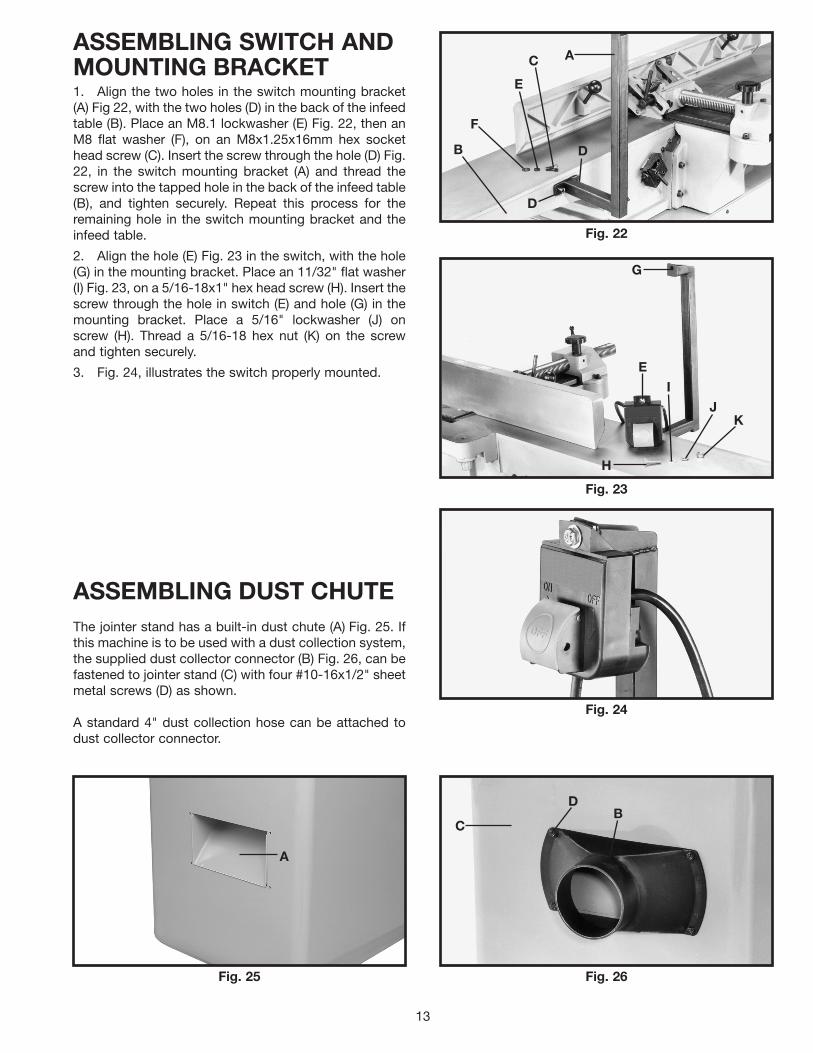
ASSEMBLING SWITCH ANDMOUNTING BRACKET1. Align the two holes in the switch mounting bracket(A) Fig 22, with the two holes (D) in the back of the infeedtable (B). Place an M8.1 lockwasher (E) Fig. 22, then anM8 flat washer (F), on an M8x1.25x16mm hex sockethead screw (C). Insert the screw through the hole (D) Fig.22, in the switch mounting bracket (A) and thread thescrew into the tapped hole in the back of the infeed table(B), and tighten securely. Repeat this process for theremaining hole in the switch mounting bracket and theinfeed table.
2. Align the hole (E) Fig. 23 in the switch, with the hole(G) in the mounting bracket. Place an 11/32" flat washer(I) Fig. 23, on a 5/16-18x1" hex head screw (H). Insert thescrew through the hole in switch (E) and hole (G) in themounting bracket. Place a 5/16" lockwasher (J) onscrew (H). Thread a 5/16-18 hex nut (K) on the screwand tighten securely.
3. Fig. 24, illustrates the switch properly mounted.
Fig. 22
Fig. 23
Fig. 24
A
D
DB
E
F
C
E
G
I
H
JK
Fig. 25 Fig. 26
ASSEMBLING DUST CHUTEThe jointer stand has a built-in dust chute (A) Fig. 25. Ifthis machine is to be used with a dust collection system,the supplied dust collector connector (B) Fig. 26, can befastened to jointer stand (C) with four #10-16x1/2" sheetmetal screws (D) as shown.
A standard 4" dust collection hose can be attached todust collector connector.
A
DB
C

14
OPERATING CONTROLS AND ADJUSTMENTSSTARTING AND STOPPINGJOINTER1. The on/off switch is located underneath the switchshield (B) Fig. 31. To start the jointer, move switch (A) upto the “ON” position.
2. To turn the jointer “OFF”, push down on switchshield (B) Fig. 32, as shown.
Fig. 31
B
A
Fig. 32
B
LOCKING SWITCHIN THE “OFF” POSITIONIMPORTANT: When the tool is not in use, the switchshould be locked in the “OFF” position to preventunauthorized use. Insert the shank of padlock (C) Fig.33, through the holes in the switch plate to lock theon/off switch trigger (A).
Fig. 33
C
A
INFEED TABLEADJUSTMENTS1. To raise or lower the infeed table, loosen tablelocking handle (A) Fig. 34, which is located at the rear ofthe infeed table and loosen locking handle (B) Fig. 35,which is located at the front of the infeed table.
Fig. 34
A
15
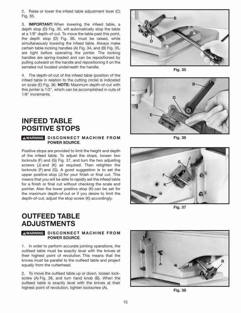
2. Raise or lower the infeed table adjustment lever (C)Fig. 35.
3. IMPORTANT: When lowering the infeed table, adepth stop (D) Fig. 35, will automatically stop the tableat a 1/8" depth-of-cut. To move the table past this point,the depth stop (D) Fig. 36, must be raised, whilesimultaneously lowering the infeed table. Always makecertain table locking handles (A) Fig. 34, and (B) Fig. 35,are tight before operating the jointer. The lockinghandles are spring-loaded and can be repositioned bypulling outward on the handle and repositioning it on theserrated nut located underneath the handle.
4. The depth-of-cut of the infeed table (position of theinfeed table in relation to the cutting circle) is indicatedon scale (E) Fig. 36. NOTE: Maximum depth-of-cut withthis jointer is 1/2", which can be accomplished in cuts of1/8" increments.
Fig. 35
Fig. 36
B
D
E
B
D
INFEED TABLEPOSITIVE STOPS
D I S C O N N E C T M A C H I N E F R O MPOWER SOURCE.
Positive stops are provided to limit the height and depthof the infeed table. To adjust the stops, loosen twolocknuts (F) and (G) Fig. 37, and turn the two adjustingscrews (J) and (K) as required. Then retighten thelocknuts (F) and (G). A good suggestion is to set theupper positive stop (J) for your finish or final cut. Thismeans that you will be able to rapidly set the infeed tablefor a finish or final cut without checking the scale andpointer. Also the lower positive stop (K) can be set forthe maximum depth-of-cut or if you desire to limit thedepth-of-cut, adjust the stop screw (K) accordingly.
Fig. 37
K
F
GJ
OUTFEED TABLEADJUSTMENTS
D I S C O N N E C T M A C H I N E F R O MPOWER SOURCE.
1. In order to perform accurate jointing operations, theoutfeed table must be exactly level with the knives attheir highest point of revolution. This means that theknives must be parallel to the outfeed table and projectequally from the cutterhead.
2. To move the outfeed table up or down, loosen lock-screw (A) Fig. 38, and turn hand knob (B). When theoutfeed table is exactly level with the knives at theirhighest point of revolution, tighten lockscrew (A).
Fig. 38
AB
16
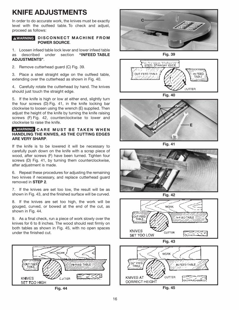
KNIFE ADJUSTMENTSIn order to do accurate work, the knives must be exactlylevel with the outfeed table. To check and adjust,proceed as follows:
D I S C O N N E C T M A C H I N E F R O MPOWER SOURCE.
1. Loosen infeed table lock lever and lower infeed tableas described under section “INFEED TABLEADJUSTMENTS”.
2. Remove cutterhead guard (C) Fig. 39.
3. Place a steel straight edge on the outfeed table,extending over the cutterhead as shown in Fig. 40.
4. Carefully rotate the cutterhead by hand. The knivesshould just touch the straight edge.
5. If the knife is high or low at either end, slightly turnthe four screws (D) Fig. 41, in the knife locking barclockwise to loosen using the wrench (E) supplied. Thenadjust the height of the knife by turning the knife raisingscrews (F) Fig. 42, counterclockwise to lower andclockwise to raise the knife.
C A R E M U S T B E TA K E N W H E NHANDLING THE KNIVES, AS THE CUTTING EDGESARE VERY SHARP.
If the knife is to be lowered it will be necessary tocarefully push down on the knife with a scrap piece ofwood, after screws (F) have been turned. Tighten fourscrews (D) Fig. 41, by turning them counterclockwise,after adjustment is made.
6. Repeat these procedures for adjusting the remainingtwo knives if necessary, and replace cutterhead guardremoved in STEP 2.
7. If the knives are set too low, the result will be asshown in Fig. 43, and the finished surface will be curved.
8. If the knives are set too high, the work will begouged, curved, or bowed at the end of the cut, asshown in Fig. 44.
9. As a final check, run a piece of work slowly over theknives for 6 to 8 inches. The wood should rest firmly onboth tables as shown in Fig. 45, with no open spacesunder the finished cut.
Fig. 39
C
Fig. 40
Fig. 41
Fig. 42
D
E
F
F
Fig. 43
Fig. 44 Fig. 45
17
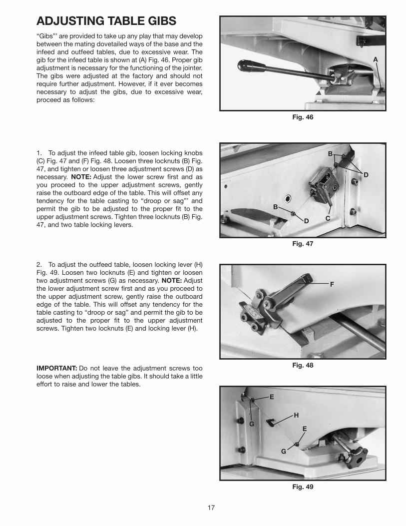
ADJUSTING TABLE GIBS“Gibs”’ are provided to take up any play that may developbetween the mating dovetailed ways of the base and theinfeed and outfeed tables, due to excessive wear. Thegib for the infeed table is shown at (A) Fig. 46. Proper gibadjustment is necessary for the functioning of the jointer.The gibs were adjusted at the factory and should notrequire further adjustment. However, if it ever becomesnecessary to adjust the gibs, due to excessive wear,proceed as follows:
1. To adjust the infeed table gib, loosen locking knobs(C) Fig. 47 and (F) Fig. 48. Loosen three locknuts (B) Fig.47, and tighten or loosen three adjustment screws (D) asnecessary. NOTE: Adjust the lower screw first and asyou proceed to the upper adjustment screws, gentlyraise the outboard edge of the table. This will offset anytendency for the table casting to “droop or sag”’ andpermit the gib to be adjusted to the proper fit to theupper adjustment screws. Tighten three locknuts (B) Fig.47, and two table locking levers.
2. To adjust the outfeed table, loosen locking lever (H)Fig. 49. Loosen two locknuts (E) and tighten or loosentwo adjustment screws (G) as necessary. NOTE: Adjustthe lower adjustment screw first and as you proceed tothe upper adjustment screw, gently raise the outboardedge of the table. This will offset any tendency for thetable casting to “droop or sag” and permit the gib to beadjusted to the proper fit to the upper adjustmentscrews. Tighten two locknuts (E) and locking lever (H).
IMPORTANT: Do not leave the adjustment screws tooloose when adjusting the table gibs. It should take a littleeffort to raise and lower the tables.
Fig. 46
Fig. 47
Fig. 48
Fig. 49
A
B
D
B
D
C
F
E
E
G
GH

18
FENCE OPERATIONThe fence can be moved across the table and can tilt45 degrees right or left at any position on the table asfollows:NOTE: SWITCH HAS BEEN REMOVED FOR CLARITYOF ILLUSTRATIONS ONLY.1. To move the fence across the table, loosen lock handle(A) Fig. 50, and turn knob (B) until desired fence locationis reached. Then tighten lock handle (A). As the fence ismoved across the table, the rear cutterhead guard (C)covers and guards the cutterhead in back of the fence.NOTE: Lock handle (A) is spring-loaded and can berepositioned by pulling up on the handle andrepositioning it on the serrated nut located underneaththe hub of the handle.2. To tilt the fence in or out, loosen lock handle (D) Fig.50. While holding fence tilting handle (E) Fig. 51, rotate90° flip stop (G) and tilt the fence to the desired angle, inor out, and tighten lock handle (D) Fig. 50. IMPORTANT:When cutting bevels and the angle is small, there is littledifference whether the fence is tilted in or out; however,at angles approaching 45 degrees it may becomedifficult to hold the work securely against the fencewhen the fence is tilted out. In these cases we suggestthat the fence be tilted toward the table, as shown in Fig.52. The fence will form a V-shape with the tables and thework is easily pressed into the pocket while passingacross the knives.
Fig. 50
Fig. 51
Fig. 52
A
B
CD
E
G
ADJUSTING FENCEPOSITIVE STOPSNOTE: SWITCH HAS BEEN REMOVED FOR CLARITYOF ILLUSTRATIONS ONLY!
The fence has been equipped with positive stops thatallow you to rapidly tilt the fence to 90 degree and 45degree angles, inward and outward, to the table. To checkand adjust the positive stops, proceed as follows:
D I S C O N N E C T M A C H I N E F R O MPOWER SOURCE.
1. Position the fence at 90 degrees to the table. Makecertain flip stop (F) Fig. 53, is lowered as shown, andadjustment screw (H) is contacting the flip stop (F); thentighten locking handle (D).
2. Place a square (K) Fig. 53, on the table and againstthe fence as shown to check if the fence is 90 degrees tothe table.
3. If an adjustment is necessary, loosen locking handle(D) Fig. 53, and locknut (L). Rotate adjustment screw (F)until you are certain the fence is 90 degrees to the table.Tighten locknut (L). Fig. 53
L
F
H
D
K

19
4. Rotate flip stop (F) Fig. 54, and tilt the fence outwardas far as it will go and tighten locking handle (D). Placea square (K) on the table and against the fence to checkif the fence is 45 degrees outward to the table.
5. If an adjustment to the positive stop is necessary,loosen locking handle (D) Fig. 54, and locknut (M). Rotateadjustment screw (N) until you are certain the fence is 45degrees outward to the table. Tighten locknut (M).
6. Tilt the fence (G) Fig. 55, inward as far as it will goand tighten locking handle (D). Using a square (K) on thetable and against the fence, check if the fence is 45degrees inward to the table.
7. If an adjustment is necessary, loosen locknut (P)Fig. 55. Rotate screw (R) until you are certain the fenceis 45 degrees inward to the table. Tighten locknut (P)and locking handle (D).
Fig. 54
Fig. 55
K
D
N
M F
G
P
R
D
K
REMOVING, REPLACING,AND RESETTING KNIVESIf the knives are removed from the cutterhead for re-placement or sharpening, care must be used inremoving, replacing, and resetting them.
D I S C O N N E C T M A C H I N E F R O MPOWER SOURCE.
1. Move the fence to the rear and remove thecutterhead guard.
BE EXTREMELY CAREFUL THATYOUR HANDS DO NOT COME IN CONTACT WITHTHE KNIVES. THE KNIVES ARE VERY SHARP.
2. Using wrench (A) Fig. 56, slightly loosen the fourlocking screws (B) in each knife slot by turning thescrews (B) clockwise.
3. Loosen screws (B) Fig. 56, further and remove knifeand knife locking bar.
4. Fig. 57, shows the knife (C) and knife locking bar (D)removed from the cutterhead. Remove the remainingtwo knives and locking bars, in the same manner.
5. Using wrench (E) Fig. 57, lower the two knifeadjustment blocks by turning screws (F) counterclockwisein all three slots of the cutterhead.
6. Before replacing knives make certain the knifelocking bars are thoroughly clean and free of gum andpitch.
7. Replace the knife locking bars (D) Fig. 57, and knives(C) into each slot in the cutterhead.
C A R E M U S T B E TA K E N W H E NINSERTING THE KNIVES AS THE CUTTING EDGESARE VERY SHARP. Push the knife down as far aspossible and snug up the screws (B) Fig. 56, by turningeach screw counterclockwise just enough to hold theknife in position. Replace the remaining two knifes in thesame manner.
Fig. 56
Fig. 57
A
B
E
F
F
D
C

20
K N I V E S M U S T B E I N S TA L L E DCORRECTLY AS SHOWN IN FIG. 58.
8. The knives are adjusted correctly when the cuttingedge of the knife extends out .060” from the cutterheaddiameter.
9. Carefully rotate the cutterhead (G) Fig. 59, until theround portion of the cutterhead is on top as shown.
10. Place a .060” feeler gage (H) Fig. 59, on thecutterhead and using a straight edge (J) on the rear tableadjust the height of the rear table until it is .060” abovethe cuttinghead diameter, as shown.
11. Lock the rear table in position and remove the feelergage.
12. Lower the infeed table and place a straight edge (J)Fig. 60, on the outfeed table extending over thecutterhead as shown.
13. Rotate the cutterhead by hand until the knife is at itshighest point at each end of the cutterhead. To raise theknife, use wrench (E) Fig. 60, and turn raising screwclockwise until the knife just touches the straight edge(J) on each end and center of the cutterhead when theknife is at its highest point. When you are certain theknife is adjusted properly, tighten the four lockingscrews (B) by turning them counterclockwise.
14. Adjust the remaining two knives in the same manner.MAKE CERTAIN THAT ALL KNIVES ARE SECURELYFASTENED IN CUTTERHEAD BEFORE TURNING ONPOWER.
15. Replace cutterhead guard.
Fig. 58
Fig. 59
Fig. 60
J
H
G
E
J
B
B

21
OPERATIONThe following directions will give the beginner a start onjointer operations. Use scrap pieces of lumber to checksettings and to get the feel of the operations beforeattempting regular work.
THE KNIVES ON THE JOINTER WILLNOT WEAR EVENLY BY FEEDING THE WOODTHROUGH THE SAME SPOT ON THE TABLE EVERYTIME. FEED THE WOOD THROUGH THE JOINTER ATDIFFERENT SPOTS ON THE TABLE WHENPOSSIBLE, TO HELP ELIMINATE UNEVEN WEAR OFTHE KNIVES.
ALWAYS USE CUTTERHEAD GUARDAND KEEP HANDS AWAY FROM CUTTERHEAD.ALWAYS USE PUSH BLOCKS WHENEVERPOSSIBLE. NEVER MAKE JOINTING AND PLANINGCUTS DEEPER THAN 1/8" IN ONE PASS.
PLACEMENT OF HANDSDURING FEEDINGAt the start of the cut, the left hand holds the work firmlyagainst the infeed table and fence, while the right handpushes the work toward the knives. After the cut is un-derway, the new surface rests firmly on the outfeed tableas shown in Fig. 61. The left hand should then be movedto the work on the outfeed table, at the same timemaintaining flat contact with the fence. The right handpresses the work forward, and before the right handreaches the cutterhead, it should be moved to the workon the outfeed table.
NEVER PASS HANDS DIRECTLY OVERTHE CUTTERHEAD.
JOINTING AN EDGEThis is the most common operation for the jointer, thesecuts are made to square an edge of a workpiece. Set theguide fence square with the table. Depth of cut should bethe minimum required to obtain a straight edge. Hold thebest face of the piece firmly against the fence throughoutthe feed as shown in Fig. 62.
MAXIMUM DEPTH OF CUT SHOULDNOT BE MORE THAN 1/8" IN ONE PASS.
DO NOT PERFORM JOINTINGOPERATIONS ON MATERIAL SHORTER THAN 10INCHES, NARROWER THAN 3/4 INCH, OR LESSTHAN 1/2 INCH THICK (REFER TO FIG. 63).
Fig. 61
Fig. 62
Fig. 63

22
SURFACINGSurfacing is identical to the jointing operation except forthe position of the workpiece. For surfacing, the major flatsurface of the workpiece is placed on the infeed table ofthe jointer with the narrow edge of the workpiece againstthe fence, as shown in Fig. 64. The workpiece ismoved from the infeed table, across the cutterhead to theoutfeed table establishing a flat surface on the workpiece
ALWAYS USE PUSH BLOCKS WHENPERFORMING SURFACING OPERATIONS AND NEVERPASS YOUR HANDS DIRECTLY OVER THECUTTERHEAD.
MAXIMUM DEPTH OF CUT SHOULDNOT BE MORE THAN 1/8" IN ONE PASS.
To cut a bevel, lock the fence at the required angle andrun the work across the knives while keeping the workfirmly against the fence and tables. Several passes maybe necessary to arrive at the desired result. When theangle is small, there is little difference whether the fenceis tilted to the right or left. However, at greater anglesapproaching 45 degrees, it is increasingly difficult tohold the work properly when the fence is tilted to theright. The advantage of the double-tilting fence isappreciated under such conditions. When tilted to theleft, the fence forms a V-shape with the tables, as shownin Fig. 65, and the work is easily pressed into the pocketwhile passing it across the knives. If the bevel is laid outon the piece in such direction that this involves cuttingagainst the grain, it will be better to tilt the fence to theright.
TAPER CUTSOne of the most useful jointer operations is cutting an edge to a taper. This method can be used on a wide variety ofwork. Tapered legs of furniture are a common example. Instead of laying the piece on the infeed table, lower theforward end of the work onto the outfeed table. Do this very carefully, as the piece will span the knives, and they willtake a “bite” from the work with a tendency to kick back unless the piece is firmly held. Now push the work forwardas in ordinary jointing. The effect is to surface off all the stock in front of the knives, to increasing depth, leaving atapered surface. The ridge left by the knives when starting the taper may be removed by taking a very light cutaccording to the regular method for jointing, with the infeed table raised to its usual position. Practice is required in thisoperation, and the beginner is advised to make trial cuts on waste material. Taper cuts over part of the length and anumber of other special operations can easily be done by the experienced craftsman.
CUTTING A RABBETWhen making a rabbet cut, as shown in Fig. 66, the cutter-head guard must be removed.
AFTER THE RABBET CUT IS COMPLETED,BE CERTAIN GUARD IS REPLACED.1. Adjust the fence so that the distance between theend of the knives and the fence is equal to the width ofthe rabbet.2. Lower the infeed table an amount equal to the depthof the rabbet. If the rabbet is quite deep, it may benecessary to cut it in two or more passes. In that event,the table is lowered an amount equal to about half thedepth of the rabbet for the first pass, then lowered againto proper depth to complete the cut.
BEVELING
Fig. 64
Fig. 65
Fig. 66

23
SURFACING WARPED PIECESIf the wood to be surfaced is dished or warped, takelight cuts until the surface is flat. Avoid forcing suchmaterial down against the table; excessive pressure willspring it while passing the knives, and it will spring backand remain curved after the cut is completed.
SURFACING SHORTOR THIN WORK
WHEN SURFACING SHORT OR THINPIECES, ALWAYS USE PUSH BLOCKS TO MINIMIZEALL DANGER TO THE HANDS. Fig. 67, illustrates usingthe Delta Push Blocks properly.
DO NOT PERFORM SURFACINGOPERATIONS ON MATERIAL SHORTER THAN 10INCHES, NARROWER THAN 3/4 INCH, WIDER THAN8 INCHES, OR LESS THAN 1/2 INCH THICK (REFERTO FIG. 68).
DIRECTION OF GRAINAvoid feeding work into the jointer against the grain asshown in Fig. 69. The result will be chipped andsplintered edges. Feed with the grain as shown in Fig.70, to obtain a smooth surface.
Fig. 67
Fig. 68
MINIMUM AND MAXIMUM SURFACINGDIMENSIONS
Fig. 69 Fig. 70
After considerable use, the knives will become dull and it will not be possible to do accurate work. Unlessbadly damaged by running into metal or other hard material, the knives may be sharpened as follows:
WHETTING KNIVESDISCONNECT MACHINE FROM POWERSOURCE.
Use a fine carborundum stone, cover it partly with paperas indicated in Fig. 71 to avoid marking the table. Laythe stone on the infeed table, lower the table and turnthe cutterhead forward until the stone lies flat on thebevel of the knife as shown. Hold the cutterhead fromturning, and whet the beveled edge of the knife, strokinglengthwise by sliding the stone back and forth acrossthe table. Do the same amount of whetting on each ofthe three knives.
Fig. 71
MAINTENANCE AND REPAIRS

24
PU
SH
STI
CK
MA
KE
FRO
M 1
/2"
OR
3/4"
WO
OD
OR
THIC
KN
ES
SLE
SS
THA
NW
IDTH
OF
MAT
’L.
TOB
EC
UT
CU
TO
FFH
ER
ETO
PU
SH
1/4
" W
OO
D
CU
TO
FFH
ER
ETO
PU
SH
1/2
" W
OO
D
NO
TCH
TOH
ELP
PR
EV
EN
TH
AN
DFR
OM
SLI
PP
ING
1/2"
SQ
UA
RE
S
CONSTRUCTING A PUSH STICKNarrow pieces of stock that are close to 10 inch minimum length should be handled with a push stick
and push block. The Fig. below is a pattern for a push stick.

25
NOTES

26
NOTES

27
PARTS, SERVICE OR WARRANTY ASSISTANCEAll Delta Machines and accessories are manufactured to high quality standards and are serviced by a networkof Porter-Cable • Delta Factory Service Centers and Delta Authorized Service Stations. To obtain additionalinformation regarding your Delta quality product or to obtain parts, service, warranty assistance, or the locationof the nearest service outlet, please call 1-800-223-7278 (In Canada call 1-800-463-3582).
A complete line of accessories is available from your Delta Supplier, Porter-Cable • Delta Factory Service Centers,and Delta Authorized Service Stations. Please visit our Web Site www.deltamachinery.com for a catalog or for thename of your nearest supplier.
Since accessories other than those offered by Delta have not been tested with this product, use of such accessories could be hazardous. For safest operation, only Delta recommended accessories should be used with this product.
ACCESSORIES
Two Year Limited New Product WarrantyDelta will repair or replace, at its expense and at its option, any new Delta machine, machine part, or machine accessorywhich in normal use has proven to be defective in workmanship or material, provided that the customer returns the productprepaid to a Delta factory service center or authorized service station with proof of purchase of the product within twoyears and provides Delta with reasonable opportunity to verify the alleged defect by inspection. For all refurbished Deltaproduct, the warranty period is 180 days. Delta may require that electric motors be returned prepaid to a motormanufacturer’s authorized station for inspection and repair or replacement. Delta will not be responsible for any asserteddefect which has resulted from normal wear, misuse, abuse or repair or alteration made or specifically authorized byanyone other than an authorized Delta service facility or representative. Under no circumstances will Delta be liable forincidental or consequential damages resulting from defective products. This warranty is Delta’s sole warranty and setsforth the customer’s exclusive remedy, with respect to defective products; all other warranties, express or implied, whetherof merchantability, fitness for purpose, or otherwise, are expressly disclaimed by Delta.

The following are trademarks of PORTER-CABLE·DELTA (Las siguientes son marcas registradas de PORTER-CABLE S.A.): Auto-Set®,BAMMER®, B.O.S.S.®, Builder’s Saw®, Contractor’s Saw®, Contractor’s Saw II™, Delta®, DELTACRAFT®, DELTAGRAM™, Delta Series2000™, DURATRONIC™, Emc²™, FLEX®, Flying Chips™, FRAME SAW®, Homecraft®, INNOVATION THAT WORKS®, Jet-Lock®,JETSTREAM®, ‘kickstand®, LASERLOC®, MICRO-SET®, Micro-Set®, MIDI LATHE®, MORTEN™, NETWORK™, OMNIJIG®, POCKETCUTTER®, PORTA-BAND®, PORTA-PLANE®, PORTER-CABLE®&(design), PORTER-CABLE®PROFESSIONAL POWER TOOLS, Posi-Matic®,Q-3®&(design), QUICKSAND®&(design), QUICKSET™, QUICKSET II®, QUICKSET PLUS™, RIPTIDE™&(design), SAFE GUARD II®, SAFE-LOC®, Sanding Center®, SANDTRAP®&(design), SAW BOSS®, Sawbuck™, Sidekick®, SPEED-BLOC®, SPEEDMATIC®, SPEEDTRONIC®,STAIR EASE®, The American Woodshop®&(design), The Lumber Company®&(design), THE PROFESSIONAL EDGE®, THE PROFESSIONALSELECT®, THIN-LINE™, TIGER®, TIGER CUB®, TIGER SAW®, TORQBUSTER®, TORQ-BUSTER®, TRU-MATCH™, TWIN-LITE®,UNIGUARD®, Unifence®, UNIFEEDER™, Unihead®, Uniplane™, Unirip®, Unisaw®, Univise®, Versa-Feeder®, VERSA-PLANE® , WHISPERSERIES®, WOODWORKER’S CHOICE™. Trademarks noted with ™ and ® are registered in the United States Patent and Trademark Office and may also be registered in othercountries. Las Marcas Registradas con el signo de ™ y ® son registradas por la Oficina de Registros y Patentes de los Estados Unidos ytambién pueden estar registradas en otros países.
PORTER-CABLE • DELTA SERVICE CENTERS(CENTROS DE SERVICIO DE PORTER-CABLE • DELTA)
Parts and Repair Service for Porter-Cable • Delta Machinery are Available at These Locations(Obtenga Refaccion de Partes o Servicio para su Herramienta en los Siguientes Centros de Porter-Cable • Delta)
Authorized Service Stations are located in many large cities. Telephone 800-438-2486 or 731-541-6042 for assistance locating one.Parts and accessories for Porter-Cable·Delta products should be obtained by contacting any Porter-Cable·Delta Distributor, AuthorizedService Center, or Porter-Cable·Delta Factory Service Center. If you do not have access to any of these, call 800-223-7278 and you willbe directed to the nearest Porter-Cable·Delta Factory Service Center. Las Estaciones de Servicio Autorizadas están ubicadas en muchasgrandes ciudades. Llame al 800-438-2486 ó al 731-541-6042 para obtener asistencia a fin de localizar una. Las piezas y los accesoriospara los productos Porter-Cable·Delta deben obtenerse poniéndose en contacto con cualquier distribuidor Porter-Cable·Delta, Centrode Servicio Autorizado o Centro de Servicio de Fábrica Porter-Cable·Delta. Si no tiene acceso a ninguna de estas opciones, llame al800-223-7278 y le dirigirán al Centro de Servicio de Fábrica Porter-Cable·Delta más cercano.
ARIZONATempe 85282 (Phoenix)2400 West Southern AvenueSuite 105Phone: (602) 437-1200Fax: (602) 437-2200
CALIFORNIAOntario 91761 (Los Angeles)3949A East Guasti RoadPhone: (909) 390-5555Fax: (909) 390-5554San Leandro 94577 (Oakland)3039 Teagarden StreetPhone: (510) 357-9762Fax: (510) 357-7939
COLORADOArvada 80003 (Denver)8175 Sheridan Blvd., Unit SPhone: (303) 487-1809Fax: (303) 487-1868
FLORIDADavie 33314 (Miami)4343 South State Rd. 7 (441)Unit #107Phone: (954) 321-6635Fax: (954) 321-6638
Tampa 33609 4538 W. Kennedy BoulevardPhone: (813) 877-9585Fax: (813) 289-7948
GEORGIAForest Park 30297 (Atlanta)5442 Frontage Road,Suite 112Phone: (404) 608-0006Fax: (404) 608-1123
ILLINOISAddison 60101 (Chicago)400 South Rohlwing Rd.Phone: (630) 424-8805Fax: (630) 424-8895
Woodridge 60517 (Chicago)2033 West 75th StreetPhone: (630) 910-9200Fax: (630) 910-0360
MARYLANDElkridge 21075 (Baltimore)7397-102 Washington Blvd.Phone: (410) 799-9394Fax: (410) 799-9398
MASSACHUSETTSBraintree 02185 (Boston)719 Granite StreetPhone: (781) 848-9810Fax: (781) 848-6759Franklin 02038 (Boston)Franklin Industrial Park101E Constitution Blvd.Phone: (508) 520-8802Fax: (508) 528-8089
MICHIGANMadison Heights 48071 (Detroit)30475 Stephenson HighwayPhone: (248) 597-5000Fax: (248) 597-5004
MINNESOTAMinneapolis 554295522 Lakeland Avenue NorthPhone: (763) 561-9080Fax: (763) 561-0653
MISSOURINorth Kansas City 641161141 Swift AvenuePhone: (816) 221-2070Fax: (816) 221-2897
St. Louis 631197574 Watson RoadPhone: (314) 968-8950Fax: (314) 968-2790
NEW YORKFlushing 11365-1595 (N.Y.C.)175-25 Horace Harding Expwy.Phone: (718) 225-2040Fax: (718) 423-9619
NORTH CAROLINACharlotte 282709129 Monroe Road, Suite 115Phone: (704) 841-1176Fax: (704) 708-4625
OHIOColumbus 432144560 Indianola AvenuePhone: (614) 263-0929Fax: (614) 263-1238
Cleveland 441258001 Sweet Valley DriveUnit #19Phone: (216) 447-9030Fax: (216) 447-3097
OREGONPortland 972304916 NE 122 nd Ave.Phone: (503) 252-0107Fax: (503) 252-2123
PENNSYLVANIAWillow Grove 19090520 North York RoadPhone: (215) 658-1430Fax: (215) 658-1433
TEXASCarrollton 75006 (Dallas)1300 Interstate 35 N, Suite 112Phone: (972) 446-2996Fax: (972) 446-8157
Houston 770384321 Sam Houston Parkway,WestSuite 180Phone: (281) 260-8887Fax: (281) 260-9989
WASHINGTONAuburn 98001(Seattle)3320 West Valley HWY, NorthBuilding D, Suite 111Phone: (253) 333-8353Fax: (253) 333-9613
Printed in U.S.A. PC-0603-149
CANADIAN PORTER-CABLE • DELTA SERVICE CENTERSALBERTABay 6, 2520-23rd St. N.E.Calgary, AlbertaT2E 8L2Phone: (403) 735-6166Fax: (403) 735-6144
BRITISH COLUMBIA8520 Baxter PlaceBurnaby, B.C.V5A 4T8Phone: (604) 420-0102Fax: (604) 420-3522
MANITOBA1699 Dublin AvenueWinnipeg, ManitobaR3H 0H2Phone: (204) 633-9259Fax: (204) 632-1976
ONTARIO505 Southgate DriveGuelph, OntarioN1H 6M7Phone: (519) 767-4132Fax: (519) 767-4131
QUÉBEC1515 ave.St-Jean Baptiste, Suite 160Québec, QuébecG2E 5E2Phone: (418) 877-7112Fax: (418) 877-7123
1447, BeginSt-Laurent, (Montréal),QuébecH4R 1V8Phone: (514) 336-8772Fax: (514) 336-3505