8. Intelligent Headlight System - Yonsei Universityweb.yonsei.ac.kr/hgjung/Lectures/AUE853/8...
33
E-mail: [email protected] http://web.yonsei.ac.kr/hgjung 8. Intelligent Headlight 8. Intelligent Headlight System System
Transcript of 8. Intelligent Headlight System - Yonsei Universityweb.yonsei.ac.kr/hgjung/Lectures/AUE853/8...

E-mail: [email protected]://web.yonsei.ac.kr/hgjung
8. Intelligent Headlight 8. Intelligent Headlight SystemSystem

E-mail: [email protected]://web.yonsei.ac.kr/hgjung
Light Distribution [1]Light Distribution [1]
• Light distribution is represented in terms of luminous intensity and illuminancepatterns.
• In accordance with the legal requirements, the values for illuminance are measured at a distance of 25m.
• The illuminance distribution is assessed on a wall at a distance of 10m in front of the headlamp.

E-mail: [email protected]://web.yonsei.ac.kr/hgjung
Light Distribution [1]Light Distribution [1]
• A sharp cut-off in the light distribution avoids dazzling oncoming traffic.
• The 15° rise in cut-off to the right-hand curb (right-hand traffic) guarantees good illumination of the driver’s own side of the road and early recognition of pedestrians, traffic signs and cyclists.

E-mail: [email protected]://web.yonsei.ac.kr/hgjung
Light Sources [1]Light Sources [1]
The halogen and xenon lamps serve as light sources for headlamps. Fig.3.6 shows a bird’s eye view of measured illuminance for a halogen and axenon system in a false-colour diagram. This shows that there is 250 %more luminous flux available when using a gas discharge light sourcerather than a halogen lamp, which gives the technician considerably moredesign freedom for the distribution of the light onto the road.

E-mail: [email protected]://web.yonsei.ac.kr/hgjung
Halogen Halogen vsvs XenonXenon
http://www.youtube.com/watch?v=jZUZ072euek
E-mail: [email protected]://web.yonsei.ac.kr/hgjung
Light Function Implementations [1]Light Function Implementations [1]
The generation of light functions with today’s headlamps is based on twodifferent technical concepts – reflection and projection technology.Reflection systems require less installation depth than projection systems,but are higher and wider.
Fig. 3.5 Two almost identical headlamps with different dipped beams: reflector dipped beam (top) and projector dipped beam (bottom) (source: Visteon)

E-mail: [email protected]://web.yonsei.ac.kr/hgjung
Light Distribution [1]Light Distribution [1]
With the reflection system the light of the bulb is distributed by the geometric shape of the reflector and optional patterning in the cover lens into the road space.
The light of the bulb is first focussed via an almost elliptical reflector in the focal plane of the lens. A shield here limits the light bundle in order to produce the cut-off. The following plano-convex aspherical lens with a typical diameter in the range of 40-75 mm projects the light onto the road.

E-mail: [email protected]://web.yonsei.ac.kr/hgjung
Areas of Light Distribution [1]Areas of Light Distribution [1]
1. fixation area – should be bright (note: for ECE headlights between 25 and 65 m,
for SAE headlights between 40 and 90 m)2. fore-field – should be fairly homogeneous but not too bright
3. right lane markings or verge – should be fairly bright and reach far
4. orientation and left lane markings – should be fairly bright, but not reach too far
5. road signs – modest illumination
6. area for overhead signs – a little illumination
7. minimal glare for oncoming drivers – practically unlit

E-mail: [email protected]://web.yonsei.ac.kr/hgjung
Advanced Front Lighting [1]Advanced Front Lighting [1]
Optimum light distribution depending on driving and environmental
conditions must be available to illuminate the road. Brightness conditions,
weather, road conditions, the traffic situation, type of road, vehicle speed
and acceleration behaviour will be taken into account by the AFS
(Advanced Front lighting System)

E-mail: [email protected]://web.yonsei.ac.kr/hgjung
Adaptive Front Lighting [1]Adaptive Front Lighting [1]
Adaptive front lighting systems (AFS) are lighting devices whichautomatically adapt the beam characteristics of the dipped and main beam to a number of different conditions.AFS introduces new classes of light distributions.These are:
Class C (Basic)

E-mail: [email protected]://web.yonsei.ac.kr/hgjung
Adaptive Front Lighting [1]Adaptive Front Lighting [1]
Class V (town)It is activated at speeds below 50 km/h or if the luminance of the road surface is higher than 1 cd/m2. The lighting performance is set to 50%.
For better visibility of pedestrians, road markings, signs and crossroads.

E-mail: [email protected]://web.yonsei.ac.kr/hgjung
Adaptive Front Lighting [1]Adaptive Front Lighting [1]
Class E (motorway)When the vehicle is moving at speeds over 110 km/h, or the road characteristics correspond to motorway conditions, the basic dipped beam is automatically moved up 0.25° to extend the range of light in the front of the vehicle. Lighting performance is set to 100%.

E-mail: [email protected]://web.yonsei.ac.kr/hgjung
Adaptive Front Lighting [1]Adaptive Front Lighting [1]
Class W (wet road)After the detection of rain or water on the road, or if the windscreen wiperis switched on, the basic class is changed to “wet road”. The illumination
of the road just in front of the vehicle is reduced to prevent glare and thereis increased light for the side of the road. Lighting performance is set to100%.

E-mail: [email protected]://web.yonsei.ac.kr/hgjung
Adaptive Front Lighting [1]Adaptive Front Lighting [1]
Class T (bending)All classes (C, V, E and W) can be modified to become a bending mode.The whole beam, or parts of it, can swivel into the bend.

E-mail: [email protected]://web.yonsei.ac.kr/hgjung
http://www.youtube.com/watch?v=KML_CGdASG4
VARILIS Adaptive Front Lighting system VARILIS Adaptive Front Lighting system

E-mail: [email protected]://web.yonsei.ac.kr/hgjung
Xenon Adaptive HeadlightXenon Adaptive Headlight
http://www.youtube.com/watch?v=qeERkO4oDVU
• Using motion sensors
E-mail: [email protected]://web.yonsei.ac.kr/hgjung
Implementation of Dynamic Bending [1]Implementation of Dynamic Bending [1]
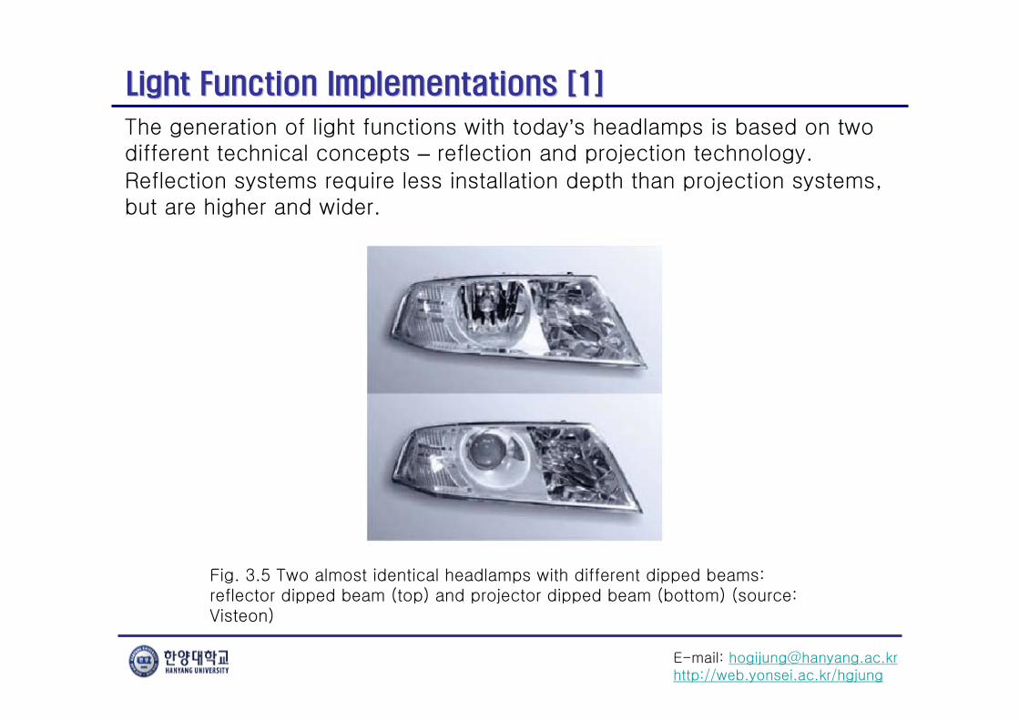
Steering angle sensorLeveling sensorSpeed sensorYaw-rate sensor
E-mail: [email protected]://web.yonsei.ac.kr/hgjung
Adjustment for Leveling [1]Adjustment for Leveling [1]
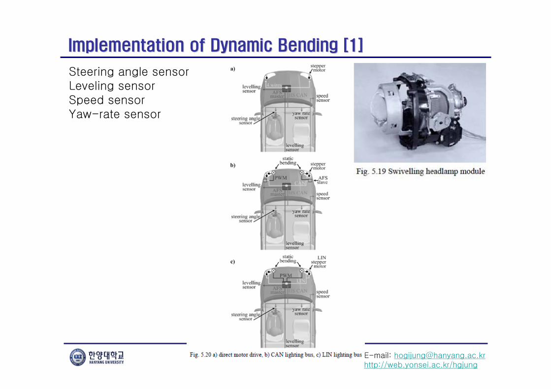
Steering angle sensorLeveling sensorSpeed sensorYaw-rate sensor

E-mail: [email protected]://web.yonsei.ac.kr/hgjung
Implementation of Light Distribution Control [1]Implementation of Light Distribution Control [1]
The shutter could undergo linear or rotational motions or a combination of both, and in each case there are three different possible axes of displacement or rotation. Fig. 5.32 shows some examples.

E-mail: [email protected]://web.yonsei.ac.kr/hgjung
Implementation of Light Distribution Control [1][2]Implementation of Light Distribution Control [1][2]
Depending on the solution chosen for the guidance of the shutter’s motion, several different actuator technologies can be used. The most widespread actuators are electromagnetic actuators (motors or voice coil actuators). But there are also piezoelectric actuators, shape memory alloys and other technologies that could be made use of.

E-mail: [email protected]://web.yonsei.ac.kr/hgjung
MercedesMercedes--BenzBenz’’s Adaptive High Beam Assists Adaptive High Beam Assist
http://www.youtube.com/watch?v=XXRiPmh_tpQ
• Camera-based vehicle detection

E-mail: [email protected]://web.yonsei.ac.kr/hgjung
GentexGentex Corporation Automatic HighCorporation Automatic High--Beam AssistBeam Assist
http://www.youtube.com/watch?v=LCQoEOmQk1I
SmartBeam
- SmartBeam HBA (Hight-Beam Assist): Auto high-beam ON/OFF
- SmartBeam VFL (Variable Forwarding Lighting): Continuously variable low
beams with auto high-beam ON/OFF
- SmartBeam DFL (Dynamic Forwarding Lighting): Constant “ON” high
beams with selective “block-out” zones

E-mail: [email protected]://web.yonsei.ac.kr/hgjung
GentexGentex Corporation Automatic HighCorporation Automatic High--Beam AssistBeam Assist
http://www.youtube.com/watch?v=LWfpfwUJ5fY
• Detection of oncoming vehicle or motorcycle
> 500m> 500m > 1,000m> 1,000m

E-mail: [email protected]://web.yonsei.ac.kr/hgjung
ReferencesReferences
1. BurkardWordenweber · JorgWallascher, Peter Boyce, Donald D. Hoffman,
Automotive Lighting and Human Vision, Springer-Verlag Berlin Heidelberg 2007.
2. Thomas Brnchen, Roland Lachmayer, Jorg Wallaschek, “Methods and tools for the design of novel multi-functional automotive lighting,”IEEE/ASME International Conference on Advanced Intelligent Mechatronics, Sep. 19-223, 1999.

E-mail: [email protected]://web.yonsei.ac.kr/hgjung
VisionVision--based Nightbased Night--time time Vehicle DetectionVehicle Detection
E-mail: [email protected]://web.yonsei.ac.kr/hgjung
NVDNVD의의 구성요소구성요소
1) Night-time vehicle detection (NVD)
2) Light blob detection
3) Light blob tracking
4) Light blob classification
5) Distance measurement

E-mail: [email protected]://web.yonsei.ac.kr/hgjung
NVD NVD 접근방법접근방법
① Light blob 검출 기반
② Light blob 검출 기반이 아닌 접근법
: appearance 기반
Deformable model, HoGEdge, Canny operatorEigenvehicles, SVMBackground suppresson, shadowShadow under the vehicle
가장 대표적인 NVD approach
LB detection (Adaptive thresholding) Blob feature-based filtering
Tracking Blob feature-based pairing

E-mail: [email protected]://web.yonsei.ac.kr/hgjung
Light Blob DetectionLight Blob Detection
① AE(Automatic exposure) 영상 기반 LB detection
② LE(Low exposure) 영상 기반 LB detection
Exposure setting 기준
AE LE
O'Malley, R., Jones, E., Glavin, M., “Rear-Lamp Vehicle Detection and Tracking in Low-Exposure Color Video for Night Conditions,” IEEE Transactions on Intelligent Transportation Systems, Volume: 11 , Issue: 2, 2010 , Page(s): 453 - 462

E-mail: [email protected]://web.yonsei.ac.kr/hgjung
Light Blob DetectionLight Blob Detection
검출 방법 기준
Dynamic thresholding
Adaptive thresholding
LoG or DoG
Simple fixed value thresholding
Multi-level thresholding
Intensity 의 local maxima detection
Region growing
i) 낮은 threshold 값(50, range = [0 255])을 통해loose하게 bright object를 추출하고 각 object의mean값(μi)과 standard deviation값(σi)을 계산
ii) ratio aspect restriction을 이용해potential vehicle과는 거리가 먼 bright object를 제거
iii)
P. F. Alcantarilla, L. M. Bergasa, P. Jiménez, I. Parra and D. F. Llorca, et al, “Automatic Light Beam Controller for driver assistance,” Machine Vision and Applications, 2011, Volume 22, Number 5, Pages 819-835
E-mail: [email protected]://web.yonsei.ac.kr/hgjung
Light Blob TrackingLight Blob Tracking
① Kalman Filtering
② Particle Filtering
③ 기타 tracking methods
Tracking parameter [x-position, y-position, x-velocity, y-velocity, width, height] [x-position, y-position, width, height]
appearance-based, Euclidean distance, nearest neighbor 등

E-mail: [email protected]://web.yonsei.ac.kr/hgjung
Light Blob ClassificationLight Blob Classification
Feature :
- 대부분 shape 또는 intensity를 feature로 하는 heuristic rule-based constraint 활용
- 후미등 구별을 위해 대부분 ‘red color 정보’를 활용
Classifier :
- 대부분 SVM을 사용
- AdaBoost, decision tree 등을 활용하는 논문 드물게 발견

E-mail: [email protected]://web.yonsei.ac.kr/hgjung
Light Blob ClassificationLight Blob Classification
1. Positional features : x, y coordinates of the blob
2. Brightness features : avg. and var. of intensity
(가까이 있을수록 밝다 / 전조등이 더 밝다)
3. Shape features : area, ratio between blob & bounding box, aspect ratio, angle,
avg of diameter, var. of diameter, size of halo 등
4. Spatial relation features : number of buddies for a blob within detected group,
두 blob이 이루는 각도 등
5. Color features : H(hue), S(saturation), V(value)
(taillight는 붉은 계열이고 headlight는 밝은 흰색일 확률이 높다)
6. Motion features : motion displacement and speed in x and y direction + direction of movement of the blob
(서로 다른종류의 LB는 일반적으로 다른 이동방향을 나타낸다)
총 37개의 SVM feature를 아래 6개의 category로 분류
Ying Li, Pankanti, S., “A performance study of an intelligent headlight control system,” IEEE Workshop on Applications of Computer Vision (WACV), 2011, Page(s): 440 - 447

E-mail: [email protected]://web.yonsei.ac.kr/hgjung
Distance MeasurementDistance Measurement
① Light blob의 y 좌표
③ 차량의 bottom-line의 y 좌표(범퍼 아래쪽 수평 edge)
② 두 후미등(LB) 사이의 거리
k : converting parameterf : focal lengthH : camera heighty : vertical coordinate of the vehicle
Perspective range estimation
두 LB 사이의 거리
LB y 좌표
범퍼 아래 수평 에지 y 좌표