8 32 - edunepal.infoedunepal.info/wp-content/uploads/2015/12/Engineering-Drawing-II...Orthographic...
11
__ .----- 06 TRIBHUV :"fNf\=.:::SITY i E::::arn. I]\:3-:-=TI.:TE OF i Level '1 BE -.l _<1_0__ : All (Except Ii 16 i Examination Control Division I""" I Programme! BAr h \ i. i I ! • C oj -; 2071 f Part ! I! II __.. i 3 ;l'S. - Engineering Drawing rI (ME45 i) ./ Candidates are required" to give answers in their own words as far as practicable. .( Attempt All questions. .( The figures in the margin indicate Full Marks. .( Assume suitable data if necessary. I 1. From the given front and side view of a solid draw the isometric view, (10] ..&'1 ' 8 32 2. Draw oblique drawing from the given orthographic views as shov,rn in figure below. [5] !. .... 1£._-: .-:r =! .L-_........ --IJ r I I • I I • I I I I • • J . L-__---l'--L.. -..J 1---.__.... r--·---- j . I , J/'?etennine the limit, allowances and type of fit for 50 H7/p6. The value of fundamental deviation given by H is zero and p is above the basic line and value is 0.032 mm, and international tOlerance given by 7 is 0.025 and 6 is 0.016 mm respectively. [4] OR !}raw tll::: top view and sectional front view of double row zig zag type riveted single strap ytt joint for 8 mm plate. B.E. [IOE] Old Questions Collection www.edunepal.info
Transcript of 8 32 - edunepal.infoedunepal.info/wp-content/uploads/2015/12/Engineering-Drawing-II...Orthographic...

__
.----06 TRIBHUV.A~~ :"fNf\=.:::SITY i E::::arn. I]\:3-:-=TI.:TE OF I.:>JG~EERING i Level '1 BE -.l Fun._M_ar_ks_<_~!_<1_0__
j~---- : All (Except pn~s ~!arks Ii 16 iExamination Control Division I"""I Programme! BAr h \ i.
iI ! • C oj -;
2071 Blu~dr2 ~ar f Part ! I! II __..J_-;..._~~me i 3 ;l'S.
Subje~t: - Engineering Drawing rI (ME45 i)
./ Candidates are required" to give L~eir answers in their own words as far as practicable.
.( Attempt All questions.
.( The figures in the margin indicate Full Marks.
.( Assume suitable data ifnecessary. I
1. From the given front and side view ofa solid draw the isometric view, (10]
..&'1 '
8
32
SideVi~
2. Draw oblique drawing from the given orthographic views as shov,rn in figure below. [5]
! . ....1£._-:
.-:r =!
.L-_........--IJ
r I I•I I•I I I I••J . L-__---l'--L.._-!--:"~ -..J
1---.__....
r--·---j . I
~I ,
J/'?etennine the limit, toleranc~ allowances and type of fit for 50 H7/p6. The value of fundamental deviation given by H is zero and p is above the basic line and value is 0.032 mm, and international tOlerance given by 7 is 0.025 and 6 is 0.016 mm respectively. [4]
OR
!}raw tll::: top view and sectional front view of double row zig zag type riveted single strapytt joint for 8 mm ~ck plate.
B.E. [IOE] Old Questions Collection
www.edunepal.info

4. Figure below shows the details of a split bearing. Draw the assembled front view with section. Talee any length for the shaft. [ 16]
.0.- _0 ... - _._._ .. -- '1"----'---"" ~- -- ..--- .. -----.- ...
• f
Mt2 STUD (M. S.) 2 OFF
~ M12 STANDRAD NUT (M. S.)
. :--eFF
I _____1 ... __..... ,_.__ ._..,.__,
\ BUSH (G. M.) ! SHAFT (M. S.)
<lOFF .' J I 'OFF ~ ...:=..- ---I ..-l-..__. ..~ .__. ,
i I
·f
.5. Draw the standard symbols for the following: [5]
a) Surface to be obtained by fine tu..-ning b) Gate valve c) Tee d) Reducer e) Thermocouple f) DC Motor g) Transformer h) Circular tube i) Fuse . j) Speaker
OR
Orthographic views of a forked end ofa machine p<L.-t are shown in figure below. Draw its sectional front view (Section B-B).
...... . -.-. . I I' ".
-+-+----- '..
".J
. ~-
***
B.E. [IOE] Old Questions Collection
www.edunepal.info

I t
I I I I I I I
I!
I •
I I
I:" •• ...C . ...,.r~X~mln:anOp. ontroi lJT/~swn
2{)71 rVlagh
._.. .§ubi!!.::~~ - Engineering Dr3wing II (!~!,,~,=-5jL ,
./ Call.didates are requir:;d to give their answers in their o\vn words as far as practicable.
./ AttemptAll questions.
./ The figures in the margin indicate Full lYfarks.
./ Necessarv figures are attached herewith.
./ Assume suitable data tfnecessary.
1. Orthographic views of an object are shovvn. in Figure P.1. Draw its isometric view. [9]
2. A cylinder having 70 !Il.."TI diameter and 40 mm height is sunnounted by a square pyramid having side 35 ffi..rn and height 50 nun. Draw the angular perspective projection when one of the side of pyramid is 30 0 inclined a.'1d its nearest comer is 30 rom behind the projection pla.11e. Take station point 35 rum in front of projection plane, 25 mrn left of nearest corner and 110 II1..m above the ground level. [6]
3. Sketch the top vie"" a.11d sectional front view of double row, single cover zig zag Butt joint.
Sketch the symbols for the folIo~ring
a) SpOt weld b) Internal thread c) Fan regulator d) 3-phase transforrn~r
e) Circuit breaker
[5J
OR
[5J
f) Hand set g) Tempie h) Material removed by turning i) Rapids j). Perpendicul~ lay
4. The assembly drawing of Rand Vice is shown in Figure PA. Draw delai. drawing of each component. Assu...rne suitable thickness if necessary. Part list is given below. [IS}
Part List i .SN Part Name Part No. I Quantity I1 )
1 1 Body 1 i 1 2 I Screw 2 I 1 ..., ...,I I '. j I .J ! S\,;re\" Base .:; 1
f---+-"-- .-=..;.:;:...:.-+---=---+----=----14 I Handle 1
Handle end 2 _,__._.I..!..::P..::i:..:,:n:..- .L-_-=2_--l.....L
S. Determine limits, tolerance, al1oWfu'1Ce and types of fit designated by 80 D9/h8. The :;J.r:cs.~~i:;r.t~tl i~e-.':atio~'1 of hoI:: is 0.0':::2 mn' r:1(~r,> than :PJndc':TIeilra] d?viation of shaft. l:n:e:r:.ctt.i.onal wllT,cncc g;:Qcks ;e,r £ anC: ') Q.: ... ~.03·:. LlIT! 'J1i..l. O.O..:i::: m::, r(;3pe~;:~v-:::y. [~;
***
B.E. [IOE] Old Questions Collection
www.edunepal.info
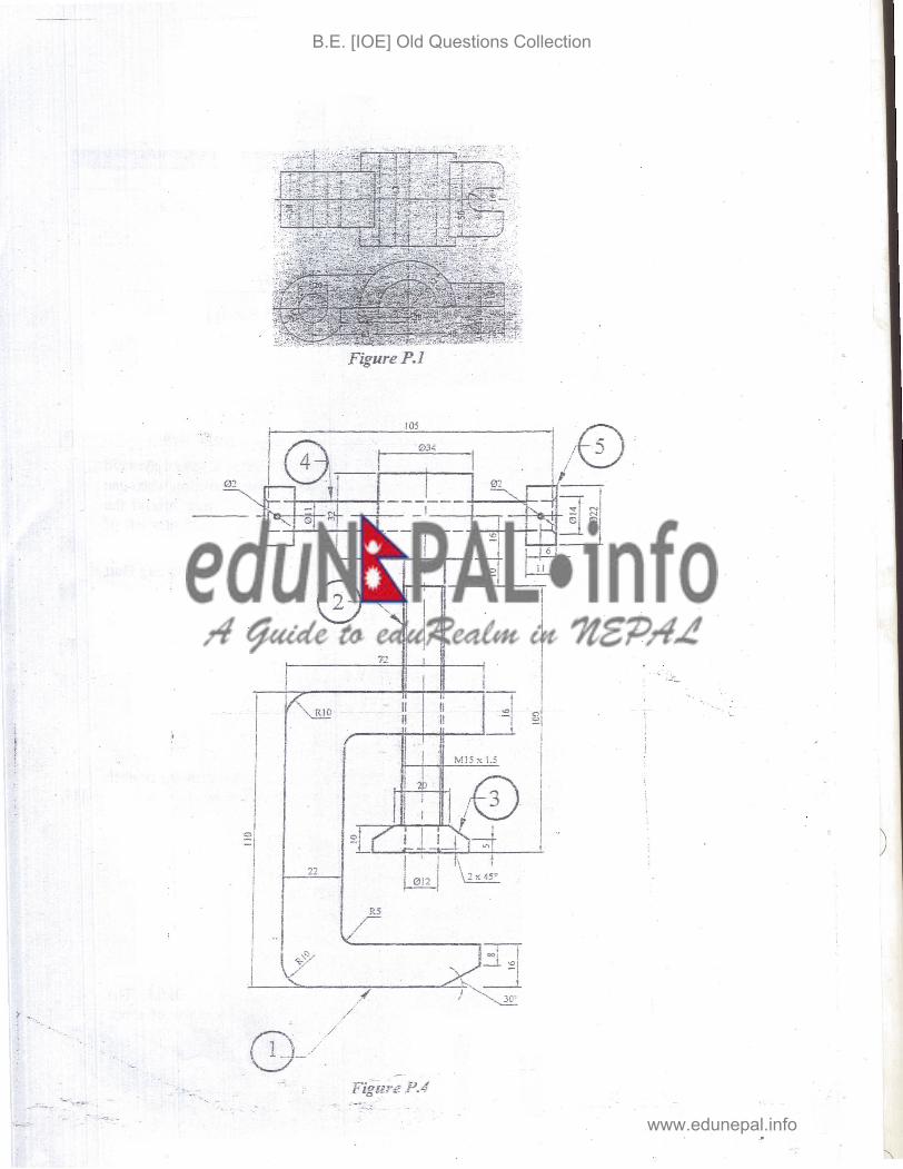
FigureP.l
II II
I ~I I
I IM!5x1.5
I l I \ f
II II I
HJ--=!'--.1H/E)1 . I ! I I _ I_I "~I )
I
I I
22
~I~
,I v= R5
i I I ~/y I t "'=
.~.
B.E. [IOE] Old Questions Collection
www.edunepal.info

06 TR..'BHlJVA,>..1 UNIV::RSITY Exam. IIZ}d:$tdNf"!tnL~~ INS-:-ITllE O~ E:NGIN=.ERL'TG L-evel ! BE - i Full M~rks ,11.0 [
,Ail (Except I ; !Examl.;-.;.auon Control Division P:rogr~mme II B..Auch) , Pass Marks ; 16 i 2070 Magh Yea:-.I PaM ! I I II i Time ' ~ hrs.
Suhject: - Enginee.-i:l; Drawing II (lviE45i)
./ Candidates are required to give their answe:s in their own words as far as practicable.
./ Attempt All questions.
.,/ The figures in the margin indicate Full Marks.
.,/ Assume suitable data ifnecessary.
1. Draw Isometric drawing of the.object shown by figure below. [10]
34 72 • i
t
5.
. .'.;.:' ~
I
i 2. A square prism of base 30 mmx30 mm base and height 50 mm is lying in the ground. t One of its sides of the base makes angle 30° with the PP and nearest comer is 10 mm l behindJhe PP. The station point is 40 mm in front ofPP and 70 mm above from GP and i-,.
contairiing by central plane. Draw the perspective view. [6]I -_ r- 3. Sketch' t~p view and sectional front view for a double riveted; double strap zig-zag butt
joint, where d=12 mm. [5J
OR ....: .. In the free hand sketch make complete fitanalj~is of the foUowingsymbols. 60861h12
given: F.D. for 'h' and'S' are 0.00 and -OJ42 respectively; ITG for 6 and 12 are 0.019 and 0.30 respectively. [Indicate type of fit, allowance, upper and lo*er deviation and shaft basis or hole basis system]
4. Sketch symbols offol1owings: i) Pond vi) Surface to be obtained without removal. of material
J
ii) School vii) Surface to be coated iii) Amplifier viii) Fluorescent bulb iv) Nipple ix) Fillet weld v) 90° elbow x) Cross
OR'
B.E. [IOE] Old Questions Collection
www.edunepal.info

Orthographic projection of an object in third angle projection is shown in fig'..:re below. Draw iTS sectional side view, section A-}·.. [5]
5. Assemble the following detail drawing shown in figure below and draw front view and to view of C-Clam . 14]
oe
..::;
"-l.\USI 0ClCAft~1..
[ i I I I I I I
1 roo T
L 1 I].,. I
~ eoov (c;n
1""
f1~
.... "'l1-_-tit •~_lNSl
, .. I
1
I•f·II·
fi·., I
Itr
.,
<;;
)
=-W~ ,oe
o1N (JotS} , .... ~*-
B.E. [IOE] Old Questions Collection
www.edunepal.info

06 T:<.I3n:~_ryAJ'JI.JNIVERSITY
~STITL~EOFENGmEL~G
! p I All (Exce;:n .Examination Control Division ! rogramme; B ,\ :.~, " . ; !'ass Marks: 16 : """\.l_.n)
; Time j 3 hrs, i2070 Bhadra i1:-ear! Part ,II II __________ _ .J
i Level j BE . ...,..'_F_u_j_ll\-._I_:l_r_k;_ ~
Subject· - EngLTleering Drawing II (ME451)
../ Candidates are required to give their answers in their own words as far as practicabie.
../ AttemptAll questZons.
../ The figures in the margin indicate Full Marks,
../ .Assume suitable data ifnecessary.
1. Orthographic views of an object are shown in figure. Draw its isometric view. [10]
...... 1~ •
.' .j.; ~.
po-A
o
l~('l.,--;__----,-+---,---~ {. c! --ltO
A -
o
I r
-0.... !r
..0 ~
1<-.--28_2. Draw oblique drawing ofthe object shoVlrrl in figure. [6] )
12
2$
12
B.E. [IOE] Old Questions Collection
www.edunepal.info
Jf Sketch the top view 2..1C se::tional front view of doubie row: zig-zag -rype lap !"iverec. joint. Take diameter- of the river as . 2 mm. . [5]
OR
DetermiIle the limits of dimensions and type of fit designatec by H7/s6 ror the basic size of 100 mm. Take fundamental deviation for Hand s respectively as 0.000 and 0.071 m.rn and ime:uational tolerance grades f.o[ 7 and 6 as 0.035 and 0.022 IIlli'1 respectively. [5]
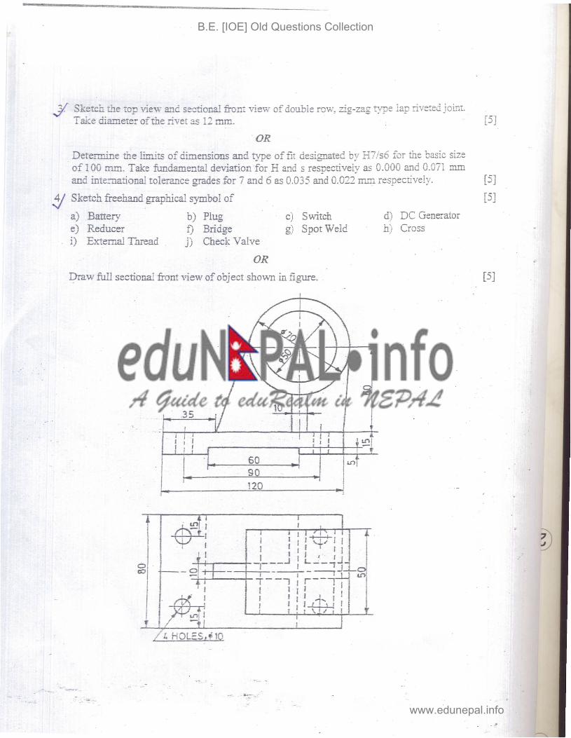
~ Sketch freehand graphical symbol of [5]
a) e) i)
Battery Reducer External Thread
b) f) j)
Plug Bridge Check Valve
c) g)
Switch Spot Weld
d) h)
DC Generator Cross
OR
Draw full sectional front view of object shown in figure. [5J
1 1I
I ! , ~I
60 ~ J~so .. 120 .,
10
-+-~---4--,
I I I I 1-+) I I I I I I I I I I I I ,. IJ
l IJ
__ .J I L..:._,
-f-T-r-,-_---,-:-;_ _ :i I I I I I I I I I I I ...J .... I I I I I l~ I I
·~l
I I1'1
B.E. [IOE] Old Questions Collection
www.edunepal.info

---
5. Assemble ~h,e pCk""ts of the f::,volving centre, shown ill figure and draw a half sectional vie',;;; from w~e frent. [14]
It 126
I,
;~ I
I ,
,I 1640 ~ll.OClI
9146
~r 9S2 I I 91'0 ¢126
+0, )..O,~lb4....,.
" I...
jI~ .- _.
e
If'-~
,.t::- I
, J , ' .........!:'.:.-.
~
I
-0"'0 ~
zll'
r M34
"I
ao c
WI o o
e
;34
,'''''
~---------+-\1\ -, ;:0 n VI n n QI..,=>"00-.00 .... ~O'< .... :lc ..• c: _.• fI. _ ....
~~~~~ii""'~
~[K .. -...- ...cru
o 0- ... ;, ;,
lC IC
-
Z D 3•
.~
? l~
... -------.: c;
**'"
B.E. [IOE] Old Questions Collection
www.edunepal.info

i 06 T?J.3h-\..;V.AJ\ Ui"ilVERSIT';' i E:~:-:;. 1-·IH1!¥timt~l!pJi:ttttMj~ INSTITUTE OF ENGINr:::?IN"G ! Lev~: I BE i Ful Marks i 40.
Examination Control Division. !P-;gramrne IAll (er.cetJtB IPass Marks: 16Arcn.)
. 2069 Bhadra i'--
Yea:-, Part I 1III i. Time ! 3 hrs.
Subject: - Engineering Dr2wingII (WJE451)
v" Candidates are required to give t.~ei:" answers i:G tb:;i:- own words as far as practi;::able. ./ Attempt All questions. ./ The figures in the margin indicate Full lrJarks. , v" Assume suitable data ifnecessary.
1. Figure below shows the orthographic projections of a guide bracket for a horizontal spindle. Draw its isometric view. [10]
60f20
I.
J-t. I I 1oD --------- ~t~:- ---.... ~ C3 <:>
I I I .., 00. ..r~, _.-..., ---------+~+' ~-.... . i I ,"
~
I .·t
I if
d,
120I· . 2. A solid square prism of 30mm side and height 60rn:m is resting with its base on the
. ground plane such that its rectangular faces are inclined at 45 degree to the picture plane and the vertical edge nearer to theP.Pis 15mmbehind it. The station point is 60mm in frorit of PP, 100mm above ground plane' and lies in the central plane, which passes from the l:enter of prism. Draw perspective view of the prism. [5]
3. Determine the limits of dimensions for the H6/s7, type of fit and fundamental deviations for the basic size of 50mm,assuming :fundamental deviation for "H" and "s" respectively as Omm above the basic size line and O.034mm above the basic size line and international tolerance grades for "6" and "7" as O.016mm and O.025mm respectively. '" [5]
OR
Sketch sectional front view and top view of double row, zig-zag type, double strap butt riveledjoint. '. [5]
4. Draw an assembled sectional front view and top view from the fqIlowing oetail drawings shovm ill figure below....· -[15]
B.E. [IOE] Old Questions Collection
www.edunepal.info

038
~----"'----t---------'-"-'
~::==:::==~ffi.l:~.BO DY C,I.
CRS,1t.O
10 201.
/. ,I
, '\I')
:
SHAFT M.~
5. Orthographic projection .of.an'object inflfst~angle ,projection'is shown in figure below. , ",,:,.:I)raw its'sectionalfront :view 'section A-A. . [5]
A
./
OR
Sketch the symbols for the following. [5]
a) N-PN type transistor b) Transformer c) Hill,contour d) Single phase motor e}" Siren f) 'Internal thread g) Elbow 90° h) Fillet _ ' i) .Surface to be obtalned by filing 'j) Highway bridge
' . ~.- - - . .....
***'.
'~'..~..-~-
B.E. [IOE] Old Questions Collection
www.edunepal.info