7DEOH RI &RQWHQWV 6HFWLRQ - aps
52
REVISION ELECTRIC SERVICE REQUIREMENTS PAGE METERING A 01/27/2022 300 METERING INSTALLATION REQUIREMENTS Table of Contents - Section 300 PARAGRAPH PAGE 300.0 METERING AND SERVICE ENTRANCE EQUIPMENT …………………………………………………………… 1 300.1 GENERAL …………………………….……………………………………………………………………… 1 300.2 METERED AND UNMETERED CONDUCTORS …………………………………………………………1 300.3 SEALING OF METERS AND METERING EQUIPMENT ……………….….…………………………… 1 300.4 UNACCEPTABLE EQUIPMENT IN SEALED AREAS .…………………………………………………. 2 301.0 METER LOCATION REQUIREMENTS .………………………….…………………………………………………. 3 301.1 METER AND SERVICE LOCATIONS .……………………………………………………………………. 3 301.2 PLANNING AND GROUPING FOR ADDITIONAL METERS …………………………………………… 3 301.3 METER LOCATIONS – RESIDENTIAL …………………………………………………………………… 3 301.3-1 METER LOCATIONS - FACTORY-BUILT BUILDINGS/HOMES .……………………………………… 3 301.3-2 RESIDENTIAL SERVICE - SINGLE DWELLING METER LOCATIONS ……………………………… 4 301.4 METER LOCATIONS - RESIDENTIAL MULTI-FAMILY BUILDINGS .………………………………… 5 301.5 METER LOCATIONS - COMMERCIAL AND INDUSTRIAL .…………………………………………… 5 301.6 UNACCEPTABLE METER LOCATIONS .………………………………………………………………… 5 301.7 WORKING SPACE (600 volts or less) .…………………………………………………………………… 6 301.8 BARRICADE/BARRIER POSTS .………………………………………………………………………… 9 301.8-1 EQUIPMENT WORKING SPACE AND ESCAPE ROUTE ................................................................ 10 301.8-2 EQUIPMENT WORKING SPACE AND ESCAPE ROUTE ................................................................ 11 301.8-3 ALTERNATE ESCAPE ROUTE ........................................................................................................ 12 301.9 METER ROOM REQUIREMENTS ………………………………………………………………………… 13 301.9-1 UNACCEPTABLE EQUIPMENT IN METER ROOMS .………………………………………………….. 17 301.9-2 METER ROOM VENTILATION .…………………………………………………………………………….17 301.10 LOCK BOX LOCATION .……………………………………………………………………………………. 17 301.11 RESIDENTIAL ELECTRIC METER CLOSET REQUIREMENTS ……………...……………………… 18 301.11-1 RESIDENTIAL ELECTRIC METER CLOSET REQUIREMENTS ……………………………………… 19 301.12 MAIN SWITCH LOCATION ………………………………………………………………………………… 20 301.13 METER AND MAIN SWITCH SEQUENCE ..………………………………………………………………20 301.14 TYPICAL SEMI-FLUSH INSTALLATION .………………………………………………………………… 20 301.15 ELECTRIC METER SEPARATION BETWEEN, GAS METER, AND FUEL SOURCES ................... 21 301.15-1 ELECTRIC, WATER AND GAS METER SEPARATION ……………...………………………………… 21 301.15-2 ESTABLISHING GAS CLEARANCES DURING CONSTRUCTION …………………………………… 22 301.15-3 REQUIRED SEPARATION FROM FUEL SOURCES …………………………………………………… 23 301.16 ROLL-UP DOORS …………………………………………………………………………………………… 24
Transcript of 7DEOH RI &RQWHQWV 6HFWLRQ - aps

REVISIONELECTRIC SERVICE REQUIREMENTS
PAGEMETERING A01/27/2022
300
METERING INSTALLATION REQUIREMENTS
Table of Contents - Section 300
PARAGRAPH PAGE
300.0 METERING AND SERVICE ENTRANCE EQUIPMENT …………………………………………………………… 1
300.1 GENERAL …………………………….……………………………………………………………………… 1
300.2 METERED AND UNMETERED CONDUCTORS …………………………………………………………1
300.3 SEALING OF METERS AND METERING EQUIPMENT ……………….….…………………………… 1
300.4 UNACCEPTABLE EQUIPMENT IN SEALED AREAS .…………………………………………………. 2
301.0 METER LOCATION REQUIREMENTS .………………………….…………………………………………………. 3
301.1 METER AND SERVICE LOCATIONS .……………………………………………………………………. 3
301.2 PLANNING AND GROUPING FOR ADDITIONAL METERS ……………………………………………3
301.3 METER LOCATIONS – RESIDENTIAL …………………………………………………………………… 3
301.3-1 METER LOCATIONS - FACTORY-BUILT BUILDINGS/HOMES .………………………………………3
301.3-2 RESIDENTIAL SERVICE - SINGLE DWELLING METER LOCATIONS ……………………………… 4
301.4 METER LOCATIONS - RESIDENTIAL MULTI-FAMILY BUILDINGS .………………………………… 5
301.5 METER LOCATIONS - COMMERCIAL AND INDUSTRIAL .…………………………………………… 5
301.6 UNACCEPTABLE METER LOCATIONS .………………………………………………………………… 5
301.7 WORKING SPACE (600 volts or less) .…………………………………………………………………… 6
301.8 BARRICADE/BARRIER POSTS .………………………………………………………………………… 9
301.8-1 EQUIPMENT WORKING SPACE AND ESCAPE ROUTE ................................................................ 10
301.8-2 EQUIPMENT WORKING SPACE AND ESCAPE ROUTE ................................................................ 11
301.8-3 ALTERNATE ESCAPE ROUTE ........................................................................................................ 12
301.9 METER ROOM REQUIREMENTS …………………………………………………………………………13
301.9-1 UNACCEPTABLE EQUIPMENT IN METER ROOMS .…………………………………………………..17
301.9-2 METER ROOM VENTILATION .…………………………………………………………………………….17
301.10 LOCK BOX LOCATION .……………………………………………………………………………………. 17
301.11 RESIDENTIAL ELECTRIC METER CLOSET REQUIREMENTS ……………...……………………… 18
301.11-1 RESIDENTIAL ELECTRIC METER CLOSET REQUIREMENTS ……………………………………… 19
301.12 MAIN SWITCH LOCATION ………………………………………………………………………………… 20
301.13 METER AND MAIN SWITCH SEQUENCE ..………………………………………………………………20
301.14 TYPICAL SEMI-FLUSH INSTALLATION .………………………………………………………………… 20
301.15 ELECTRIC METER SEPARATION BETWEEN, GAS METER, AND FUEL SOURCES ................... 21
301.15-1 ELECTRIC, WATER AND GAS METER SEPARATION ……………...………………………………… 21
301.15-2 ESTABLISHING GAS CLEARANCES DURING CONSTRUCTION …………………………………… 22
301.15-3 REQUIRED SEPARATION FROM FUEL SOURCES …………………………………………………… 23
301.16 ROLL-UP DOORS …………………………………………………………………………………………… 24

REVISIONELECTRIC SERVICE REQUIREMENTS
PAGEMETERING B03/06/2022
300
PARAGRAPH PAGE
302.0 SPECIAL CONSIDERATIONS …………………………………………………………………………………………25
302.1 METER IDENTIFICATION BY CUSTOMER ………………………………………………………………25
302.1-1 SERVICE IDENTIFICATION .………………………………………………………………………………. 25
302.2 METER HEIGHT .……………………………………………………………………………………………. 25
302.3 MAIN SWITCH .………………………………………………………………………………………………. 25
302.3-1 MULTIPLE SERVICE DISCONNECTS (Two to Six) .…………………………………………………….26
302.4 FOREIGN DEVICES IN SEALABLE CABINETS ………………………………………………………… 27
302.5 METER SOCKET ENCLOSURES ………………………………………………………………………… 27
302.6 PROPER INSTALLATION OF COUPLINGS AND GUTTERS .………………………………………… 27
302.7 TERMINATIONS OR LUGS FURNISHED BY APS (Underground) …………………………………… 27
302.8 SECURED IN PLACE (S.E.S.) .……………………………………………………………………………. 27
302.9 REQUIRED APPROVAL FOR METERING IN SERVICE EQUIPMENT ……………………………… 27
302.10 EUSERC - ELECTRIC UTILITY SERVICE EQUIPMENT REQUIREMENTS COMMITTEE .………. 28
302.11 SERVICE ENTRANCE SECTION …………………………………………………………………......…. 28
302.12 OVERHEAD RISER AND BUS DUCT RISER REQUIREMENTS .……………………………………. 28
302.13 (RESERVED) ……………..............................................................................................……………. 28
302.14 METER TYPES USED ON APS SYSTEM .………………………………………………………………. 28
303.0 SELF-CONTAINED METERING .………………………….…………………………………………………………. 29
303.1 EQUIPMENT FURNISHED AND INSTALLED BY APS - STANDARD OFFER
CUSTOMERS ONLY .………………………………………………………………………………………. 29
303.2 EQUIPMENT FURNISHED AND INSTALLED BY THE CUSTOMER ………………………………… 29
303.3 SELF-CONTAINED SOCKET RATINGS …………………………………………………………………. 29
303.4 SOCKET ENCLOSURES ..…………………………………………………………………………………. 29
303.5 METER SOCKET CLOSING DEVICES .………………………………………………………………….. 29
303.6 SAFETY TEST BLOCKS …………………………………………………………………………………… 30
303.6-1 SINGLE-PHASE SAFETY TEST BLOCK INSTALLATIONS …………………………………………… 30
303.6-2 THREE-PHASE SAFETY TEST BLOCK INSTALLATIONS ……………………………………………. 30
303.7 HIGH LEG LOCATION (3ø 4W DELTA SERVICE) ……………………………………………………… 30
303.8 CONNECTION DIAGRAM FOR SELF CONTAINED METER SOCKETS - DWG #G1 .…………….. 31
303.9 TYPICAL MULTI METERING ARRANGEMENTS - DWG#G2 ………………………………………… 32
303.10 TYPICAL UNDERGROUND SERVICE TERMINATIONS ARRANGEMENTS - DWG #G3 ………… 33
303.11 SAFETY-SOCKET BOX WITH TEST BY-PASS FACILITIES FOR MULTIPLE SELF-CONTAINED
METER INSTALLATION -DWG #G4 ……………………………………………………………….…….. 34
303.12 MULTI METERING AND SERVICE FOR SPEC BUILDINGS ………………………………................ 35
303.13 MOBILE HOME & TEMPORARY METER PEDESTAL - 1Ø 3 WIRE 120/240 VOLT SERVICE ..…. 36
303.14 120 VOLTS 1Ø 2 WIRE - METERING PEDESTAL………….................………………………………. 37

REVISIONELECTRIC SERVICE REQUIREMENTS
PAGEMETERING C01/27/2022
300
PARAGRAPH PAGE
304.0 C.T. METERING ..………………………………………………………………………………………………………. 38
304.1 EQUIPMENT FURNISHED AND INSTALLED BY APS STANDARD OFFER
CUSTOMERS ONLY ..………………………………………………………………………………………. 38
304.2 EQUIPMENT FURNISHED AND INSTALLED BY CUSTOMER ..………………………………………38
304.2-1 C.T. METER SOCKETS (See Section 300 Paragraph 305.8 for self-contained meter sockets) ...….38
304.3 POWER LEG LOCATION (3ø 4W DELTA SERVICE) ...…………………………………………………38
304.4 EQUIPMENT FURNISHED AND INSTALLED BY CUSTOMER .……………………………………… 38
304.5 OUTDOOR SERVICE ENTRANCE SECTION PADS ..………………………………………………..... 39
304.5-1 OUTDOOR SERVICE ENTRANCE SECTION PADS ..………………………………………………..... 40
304.5-2 OUTDOOR SERVICE ENTRANCE SECTION PADS ..………………………………………………..... 41
304.5-3 OUTDOOR SERVICE ENTRANCE SECTION PADS IN REMOTE LOCATIONS WITH NO
ACCESS TO WATER …………………............................................................................................... 42
304.6 INDOOR SERVICE ENTRANCE SECTION HOUSEKEEPING PADS .……………………………..... 43
305.0 INSTALLATION REQUIREMENTS FOR THE TOTALIZED METERING OF ELECTRIC LOAD .……………. 44
305.1 GENERAL RULES FOR TOTALIZED METERING INSTALLATIONS ………………………………… 44
305.2 INDOOR TOTALIZING/COMBINING CABINETS ...............................………………………………… 45
305.2-1 APS OUTDOOR TOTALIZING/COMBINING CABINET .................................................................... 46
306.0 TYPICAL STAND ALONE SERVICE ENTRANCE SUPPORTS FOR SERVICE EQUIPMENT .………..…. 47
307.0 JOB SITE POWER (TEMPORARY METER IN PERMANENT POSITION) ..……………………………………. 49

300.0 METERING AND SERVICE ENTRANCE EQUIPMENT
________________________________________________________________________________________________
300.1 GENERAL
All meter and service equipment installations shall comply with the service requirements of APS and with
rules and regulations of the inspection authorities having jurisdiction. All meter sockets and enclosures shall
be listed and approved by a recognized testing lab.
If any question arises for which you cannot find the answer in the following pages, it is suggested that you call
APS for further information. See Pages “B” and “C” in the front of this manual for telephone numbers and
addresses of local APS offices.
Whenever any electrical wiring for service connection is installed whether regulated by inspection authorities
or not, provision shall be made for the installation of metering equipment. It shall comply with these service
requirements except when existing metering equipment, in the opinion of APS, is satisfactory and adequate
to register all current to be supplied.
Whenever one meter registers the electricity supplied to two or more single family residential occupancies, it
will be considered a non-residential installation for the purpose of these requirements.
When a Customer does his own wiring, he will be considered the electrical contractor for the purpose
of these requirements.
________________________________________________________________________________________________
300.2 METERED AND UNMETERED CONDUCTORS
Line side (unmetered) and load side (metered) conductors shall not occupy the same raceway or
enclosure. Exception: Meter socket and current transformer enclosures.
________________________________________________________________________________________________
300.3 SEALING OF METERS AND METERING EQUIPMENT
All meters, meter facilities and all points of access to unmetered wiring on the Customer’s premise
shall be sealed by APS. All cabinets, conduit fittings and equipment enclosures containing unmetered
conductors shall be made sealable by the Customer before service will be energized. The breaking of
seals and tampering with meters or unmetered wiring by unauthorized persons is prohibited and
subject to penalty of the law. (See Section 100, Paragraph 100.17).
Stud and wing-nut assembly, or sealing screws shall be used for sealing all removable panels and covers to
compartments used for routing or terminating unmetered conductors.
When a stud and wing-nut assembly is used for sealing, the stud shall be 1/4” x 20 (minimum). The stud and
wing nut shall each be drilled .0635” (minimum) for sealing purposes.
All sealing screws shall be drilled .0635” (minimum) for sealing purposes.
REVISIONELECTRIC SERVICE REQUIREMENTS
PAGEMETERING 105/10/2021
300.0
2-1/2"
3/4"
1-1/4"
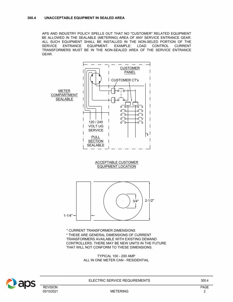
APS AND INDUSTRY POLICY SPELLS OUT THAT NO "CUSTOMER" RELATED EQUIPMENT
BE ALLOWED IN THE SEALABLE (METERING) AREA OF ANY SERVICE ENTRANCE GEAR.
ALL SUCH EQUIPMENT SHALL BE INSTALLED IN THE NON-SELED PORTION OF THE
SERVICE ENTRANCE EQUIPMENT. EXAMPLE: LOAD CONTROL CURRENT
TRANSFORMERS MUST BE IN THE NON-SEALED AREA OF THE SERVICE ENTRANCE
GEAR.
CUSTOMER
PANEL
CUSTOMER CT's
METER
COMPARTMENT
SEALABLE
120 / 240
VOLT UG
SERVICE
PULL
SECTION
SEALABLE
ACCEPTABLE CUSTOMER
EQUIPMENT LOCATION
* CURRENT TRANSFORMER DIMENSIONS
* THESE ARE GENERAL DIMENSIONS OF CURRENT
TRANSFORMERS AVAILABLE WITH EXISTING DEMAND
CONTROLLERS. THERE MAY BE NEW UNITS IN THE FUTURE
THAT WILL NOT CONFORM TO THESE DIMENSIONS.
TYPICAL 100 - 200 AMP
ALL IN ONE METER CAN - RESIDENTIAL
300.4 UNACCEPTABLE EQUIPMENT IN SEALED AREA
REVISIONELECTRIC SERVICE REQUIREMENTS
PAGEMETERING 205/10/2021
300.4

301.0 METER LOCATION REQUIREMENTS
________________________________________________________________________________________________
301.1 METER AND SERVICE LOCATIONS
APS reserves the right to determine all meter and service locations. Only authorized APS personnel
shall determine these locations. See Section 100, Paragraph 102.20 and Section 200, Paragraph 200.0.
________________________________________________________________________________________________
301.2 PLANNING AND GROUPING FOR ADDITIONAL METERS
Occasionally there is a need to locate and install additional service and metering equipment after the
originally planned electric service for a building is installed and energized.
The additional meters must be grouped with those already in services, and be installed in accordance with
the established meter location plan for the building.
The added service equipment must be located and installed in conformance with applicable codes, laws, and
ordinances of the inspection authority having jurisdiction, and with the requirements of this Service
Requirements Manual.
________________________________________________________________________________________________
301.3 METER LOCATIONS - RESIDENTIAL
For single family residential buildings, meters and metering equipment shall be installed:
a. Outdoors and mounted on or recessed in an exterior building wall, but not under a carport, breezeway,
patio, porch, or in any area that can be enclosed, or
b. Outdoors in a meter pedestal or service entrance section, but not under a carport, breezeway, patio,
porch, or in any area that can be enclosed, or
c. In a room within the building, approved by APS, for the location of electric meters, and with access only by
a door opening to the outside of the building. See Paragraph 301.9 for meter room requirements.
In addition, the meter area must be readily accessible (See Section 100, Paragraph 102.20) without requiring
passage through restricted private areas, gates or fences. See next page for acceptable meter locations for
single family residences. The meter and main switch shall be installed next to each other on the same
wall. See Paragraph 301.13.
NOTE: See Section 500, Paragraph 506.6-1 for requirements for mobile home pedestals.
________________________________________________________________________________________________
301.3-1 METER LOCATIONS - FACTORY-BUILT BUILDINGS/HOMES
Factory-built buildings and homes (FBBs) shall meet the following requirements before meters and metering
equipment can be mounted on the building:
1. FBBs shall be secured on a permanent foundation (Type E) per HUD Permanent Foundations Guide for
Manufactured Housing - December 1996 and requirements of the authority having jurisdiction.
2. The trailer tongue, axles and wheels shall be removed.
3. The meter panel shall meet all APS requirements.
4. Service entrance equipment attached to FBB’s shall be completely installed by the manufacturer of the
structure.
5. Meter location shall be per Paragraphs 301.3 or 301.5.
6. For overhead applications refer to Section 400.
7. For underground applications refer to Section 500.
NOTE: If the above requirements #1 - #3 are not met, a meter pedestal shall be required.
REVISIONELECTRIC SERVICE REQUIREMENTS
PAGEMETER LOCATION REQUIREMENTS 305/10/2021
301.0

APS RESERVES THE RIGHT TO DETERMINE ALL METER AND SERVICE LOCATIONS.
1. THE METER AND MAIN SWITCH SHALL BE ACCESSIBLE FOR READING AND
MAINTENANCE WITHOUT PASSING THROUGH RESTRICTED AREAS, GATES, OR
FENCES.
2. ALL METER AND MAIN SWITCHES SHALL BE LOCATED THREE FEET MINIMUM TO
SIX FEET MAXIMUM ON THE FRONT CORNER OF A RESIDENCE, NEAREST TO THE
POINT OF AVAILABLE SERVICE, AS DETERMINED BY APS ON AN EXTERIOR WALL
OR ALTERNATE LOCATION (SUBJECT TO LOCAL INSPECTION AUTHORITY), BUT
NOT UNDER A CARPORT, BREEZEWAY, PATIO, PORCH, OR OTHER AREA THAT CAN
BE ENCLOSED WITH BUILDING EXPANSION OR FENCE.
3. THE ELECTRIC METER AND MAIN SWITCH "MAY BE" INSTALLED AT AN ALTERNATE
LOCATION NOT ATTACHED TO A DWELLING TO ENSURE ACCESSIBILITY. (SUBJECT
TO LOCAL INSPECTION AUTHORITY APPROVAL)
4. IF OVERHEAD SERVICE IS AVAILABLE IN THE REAR OF THE PROPERTY (ALLEY OR
EASEMENT) THE POINT OF ATTACHMENT MAY BE ON THE REAR OF THE
RESIDENCE. THE METER & MAIN DISCONNECT SHALL BE LOCATED PER ITEMS #1
& #2 ABOVE. IT IS THE CUSTOMER'S RESPONSIBILITY TO INSTALL CONDUIT AND
WIRING BETWEEN THE BUILDING IN ITS ENTIRETY.
5. WHEN REMODELING EXISTING RESIDENCES, CHECK WITH LOCAL APS OFFICE.
6. SERVICE ENTRANCE EQUIPMENT SHALL BE UTILIZED FOR ITS INTENDED
PURPOSE.
ACCEPTABLE METER LOCATIONS
REAR
PROPERTY LINE
FENCE
FENCE
FENCE
FENCE
3' MIN.
6' MAX.
GARAGE/CARPORT
FRONT
PROPERTY LINE
REAR
PROPERTY LINE
STREET STREET
ALTERNATE
LOCATION
6' X 6' AREA
SES/METER
FENCE
METER LOCATION - BUILDING MOUNTED
SERVICE ENTRANCE SECTION
METER LOCATION - SERVICE PEDESTAL
NOTE: 3' MINIMUM CLEARANCE
REQUIRED AROUND ALL SIDES OF THE
SERVICE PEDESTAL.
301.3-2 RESIDENTIAL SERVICE - SINGLE DWELLING METER LOCATIONS
REVISIONELECTRIC SERVICE REQUIREMENTS
PAGEMETER LOCATION 405/10/2021
301.3-2

301.4 METER LOCATIONS - RESIDENTIAL MULTI-FAMILY BUILDINGS
1. Meters and metering equipment shall be installed:
a. Outdoors and mounted on or recessed in an exterior building wall, or
b. In a room within the building, approved by APS for the location of electric meters, and with access
only by a door opening to the outside of the building. See Paragraph 301.9 for meter room
requirements.
2. Meters and metering equipment shall not be installed within any residential occupancy.
3. Before meters can be installed in multiple residential panels, each individual meter socket must be
permanently and clearly identified. See Meter Identification, Paragraph 302.1. Permanently affixed
identification tags are also required on all apartment/condo doors and buildings.
________________________________________________________________________________________________
301.5 METER LOCATIONS - COMMERCIAL AND INDUSTRIAL
1. Location of metering to be approved by the Electric Meter Shop prior to construction.
2. For single occupancy non-residential and industrial buildings, meters and metering equipment shall be
installed:
a. Outdoors and mounted on an exterior wall with vehicle access, or
b. Within a meter room inside the building on the first floor (see Definitions, Section 100, Paragraph
102.12) and with access only by a door opening to the outside of the building with vehicle access.
See Paragraph 301.9 for meter room requirements.
3. For multiple occupancy buildings meters and metering equipment shall be located per above Number 2a
or 2b, and shall be grouped in one readily accessible central location, accessible to all occupants. Meter
sockets must be permanently and clearly identified. See Meter Identification, Paragraph 302.1.
4. In large multiple occupancy buildings, extensive shopping centers or buildings, APS may, at it’s option,
establish more than one meter location for groups of individual meter facilities. Consult APS prior to
construction for approval of service plans.
5. Service stations - the meter location shall be located such that it is a minimum of twenty (20) feet clear of
any gas pump and ten (10) feet clear of any gas storage tank fill spout and/or vent.
________________________________________________________________________________________________
301.6 UNACCEPTABLE METER LOCATIONS
For reasons of public safety, maintenance of service equipment, and reliability of metering, meters shall not
be installed in any of the following locations:
1. Inside any building, unless located within an acceptable meter room. See Paragraph 301.9.
2. In any location not readily accessible. See Section 100, Paragraph 102.20.
3. In any substation or transformer vault.
4. In any location which may be hazardous to personnel.
5. On any surface subject to excessive vibration.
6. In or accessed through any rest, bath, shower, powder, or toilet room.
7. In any elevated area.
8. In any location not providing a clear and continuously unobstructed working space extending a minimum
of three (3) feet from the face of the meter panel, and having a width to permit ready access to the
complete metering installation. See Working Space, Paragraph 301.7.
9. In any location where moisture, fumes, or dust may interfere with the operation of the meter, or materially
damage it.
10. In any location giving less than three feet clearance to any property line, or with less than three feet
clearance to any sidewalk, alley or driveway giving access to non-residential or industrial property.
11. In any basement or depressed area.
12. Within carport or patio areas which are or can become enclosed, when served Overhead or
Underground.
13. Mounted on APS poles.
14. In a room containing mechanical equipment.
15. In any elevator shaft or hatchway.
16. Mounted on any trees.
17. In any unsanitary areas in reference to farm animals and products.
18. In a plenum or any portion of a return or supply air ducting system.
19. In a drive-thru area (ex: fast food restaurants, drug stores, banks, etc.).
NOTE: If an existing meter panel has had the meter removed for more than 6 months and the panel is in an
unacceptable location, the customer is required to move the panel to a location that complies with all
applicable ESRM requirements prior to APS reconnecting the service.
REVISIONELECTRIC SERVICE REQUIREMENTS
PAGEMETER LOCATION 505/10/2021
301.4

NOTES:
1. TO PERMIT ACCESS TO THE METERING INSTALLATIONS AND PROVIDE SAFETY FOR PERSONNEL,
A WORKING AND STANDING SPACE ENTIRELY ON THE PROPERTY OF THE CUSTOMER SHALL BE
PROVIDED IN FRONT OF ALL METERING EQUIPMENT.
2. WORKSPACE SHALL BE CLEAR OF OBSTRUCTIONS, INCLUDING A/C UNITS AND PIPING SYSTEMS
AND SHALL HAVE A SLOPE TO PROVIDE DRAINAGE AWAY FROM THE METERING EQUIPMENT.
MAXIMUM SLOPE ALLOWED IS 1 INCH IN 3 FEET. THERE SHALL BE 10" MINIMUM HORIZONTAL AND
9" MINIMUM VERTICAL CLEARANCES FROM THE CENTER OF THE METER SOCKET TO ANY
OBSTRUCTION. WHEN THE PANEL WIDTH IS LESS THAN 36", THE CLEAR WORKING SPACE SHALL
BE 18" MINIMUM HORIZONTALLY FROM THE CENTER OF PANEL. IN ALL CASES THE HORIZONTAL
CLEARANCE SHALL BE THE GREATER OF EITHER THE 10" MINIMUM FROM THE CENTER OF THE
METER SOCKET TO ANY OBSTRUCTION OR 18" MINIMUM FROM CENTER OF PANEL CLEARANCE.
NEAREST CORNER OR
OTHER OBSTRUCTION
OBSTRUCTION
ABOVE METER
10"
MIN.
78" MIN. WORKING SPACE
HEIGHT
9" MIN.
48" MIN. TO 75" MAX
CLEAR
WORKING
SPACE
36"
MIN.
FIGURE 1
SURFACE OR SEMI-FLUSH
METER INSTALLATIONS
CLEAR
WORKING
SPACE
78" M
IN
.
78" MIN. WORKING
SPACE HEIGHT
36"
MIN.
FIGURE 2
WORKING SPACE - SIDE VIEW
36"
MIN.
18"
MIN.18"
MIN.
CENTER
OF
PANEL
CENTER
OF METER
SOCKET
301.7 WORKING SPACE (600 VOLTS OR LESS)
REVISIONELECTRIC SERVICE REQUIREMENTS
PAGEMINIMUM WORKING SPACE 601/27/2022
METER LOCATION301.7

WORKING SPACE AND CLEARANCE REQUIREMENTS
(TOP VIEW OF SWITCHBOARD)
INDOOR S.E.S.
MINIMUM REQUIRED
WORKING SPACE
KEEP CLEAR
LENGTH OF SWITCHBOARD
36"
MIN.
OUTDOOR S.E.S. ENCLOSED BY SCREEN WALL
BUILDING WALL
NOTE:
HINGED DOOR WHEN OPEN
MAY NOT BLOCK EXIT ROUTE.
WHEN DOORS ARE IN MAXIMUM
OPEN POSITIONS EXIT SHALL
BE 36" MINIMUM.
SCREEN WALL
OP
EN
D
OO
R
OP
EN
D
OO
R
PROPERTY LINE WALL OR OBSTRUCTION
11" MIN.
36" MIN. 36" MIN.36" MIN.
NOTE: Refer to ESRM 301.8 for additional outdoor SES working space,
clearance and escape route requirements.
301.7 WORKING SPACE AND CLEARING REQUIREMENTS
REVISIONELECTRIC SERVICE REQUIREMENTS
PAGEMINIMUM WORKING SPACE 701/27/2022
METER LOCATION301.7

MULTIPLE SERVICE ENTRANCE SECTIONS
FIGURE 1 - METER STAGGERED
APS
PULL
SECTION
METER
& CT
SECTION
CUSTOMER
BREAKER
SECTIONS
FRONT
7' MIN.
FRONT
CUSTOMER
BREAKER
SECTIONS
METER
& CT
SECTION
APS
PULL
SECTION
NOTES
1. SERVICE ENTRANCE SECTIONS THAT FACE EACH OTHER WITH
STAGGERED METER LOCATIONS SHALL HAVE A MINIMUM WORKING
SPACE OF 7 FEET BETWEEN SERVICE ENTRANCE SECTIONS.
2. TWO EXIT PATHS SHALL BE PROVIDED.
FIGURE 2 - METERS FACE - TO - FACE
9' MIN.
FRONT
CUSTOMER
BREAKER
SECTIONS
CUSTOMER
BREAKER
SECTIONS
METER
& CT
SECTION
METER
& CT
SECTION
APS
PULL
SECTION
APS
PULL
SECTION
NOTES
1. SERVICE ENTRANCE SECTIONS THAT FACE EACH OTHER WITH
FACE-TO-FACE METER LOCATIONS SHALL HAVE A MINIMUM WORKING
SPACE OF 9 FEET BETWEEN SERVICE ENTRANCE SECTIONS.
2. TWO EXIT PATHS SHALL BE PROVIDED.
FRONT
301.7 WORKING SPACE - MULTIPLE SERVICE ENTRANCE SECTIONS
REVISIONELECTRIC SERVICE REQUIREMENTS
PAGEMINIMUM WORKING SPACE 805/10/2021
METER LOCATION / MULTIPLE SERVICE ENTRANCE SECTIONS301.7

REMOVABLE POST FIXED POST
A A
CONCRETE
FILLED IN
FIELD
4-1/2"
57"
50"
34"
32"
21"
2"
4"
25"
5-1/2"
10" MIN.
2"MIN. CONCRETE
ENCASEMENT
(INCL. BOTTOM)
FINAL GRADE
DETAIL A
6'
36"
36"
SECTION A-A
BARRIER POST DETAIL
9" MIN.
6-1/2" X 3/4"
STEEL PIN
WITH 1/2"
HOLE IN
END TO
ACCEPT LOCK
7/8" HOLE IN POST
AND SLEEVE
1/2" HOLE
DETAIL A
CONSTRUCTION NOTES:
1. USE ADDITIONAL BARRIER CENTER POST AS
REQUIRED TO PREVENT TRAFFIC PENETRATIONS TO
SES.
2. CAUTION MUST BE TAKEN INSTALLING
POSTS SO THAT POSTS DO NOT MAKE CONTACT
WITH CONDUIT SYSTEM.
FINAL
GRADE
2"
3. STEEL BOLLARD SHALL NOT BE IN CONTACT WITH
THE SOIL.
4. CALL ARIZONA811 FOR BLUE STAKING AT 811, TO
GET ALL UTILITIES MARKED PRIOR TO EXCAVATION.
2"
4-1/2"
301.8 BARRICADE / BARRIER POSTS
REVISIONELECTRIC SERVICE REQUIREMENTS
PAGEBARRICADE / BARRIER POSTS 901/27/2022
301.8
THE CUSTOMER SHALL FURNISH, INSTALL AND MAINTAIN PERMANENT BARRICADES/BARRIER
POST(S) TO PROVIDE CLEARANCES AS SPECIFIED IN ESRM, SECTION 304.5-1, WHERE THE
WORKING SPACE IS EXPOSED TO VEHICLES OR HAZARDOUS CONDITIONS. APS SHALL SPECIFY
WHEN REMOVABLE POST(S) CAN BE USED. VEHICULAR TRAFFIC OR HAZARDOUS CONDITIONS
INCLUDE BUT ARE NOT LIMITED TO MOTORIZED VEHICLES, PALLET JACKS, HAND CARTS, ETC.,
THAT COULD PHYSICALLY ENTER THE WORKING SPACE OR ESCAPE ROUTE.
POSTS SHALL BE A MINIMUM 4" (4.5" OUTSIDE DIAMETER) GALVANIZED SCHEDULE 40 PIPE, OR 4"
(4.5:" OUTSIDE DIAMETER) GALVANIZED RIGID METAL CONDUIT.
301.8-1 EQUIPMENT WORKING SPACE AND ESCAPE ROUTE
REVISIONELECTRIC SERVICE REQUIREMENTS
PAGEEQUIPMENT WORKING SPACE AND ESCAPE ROUTE 1001/27/2022
301.8
SES
36" MIN
60" MAX.
36" MIN.
SES
36"
MIN
60"
MAX
36" MIN.
6"
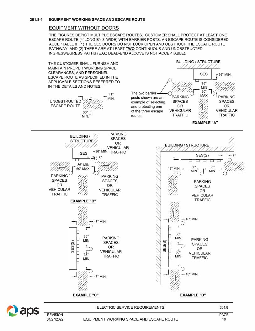
EQUIPMENT WITHOUT DOORS
BUILDING / STRUCTURE
BUILDING /
STRUCTURE
PARKING
SPACES
OR
VEHICULAR
TRAFFIC
UNOBSTRUCTED
ESCAPE ROUTE
PARKING
SPACES
OR
VEHICULAR
TRAFFIC
EXAMPLE "A"
EXAMPLE "B"
36"
MIN.
PARKING
SPACES
OR
VEHICULAR
TRAFFIC
PARKING
SPACES
OR
VEHICULAR
TRAFFIC
PARKING
SPACES
OR
VEHICULAR
TRAFFIC
36"
MIN
48" MIN.
SE
S(S
)
36"
MIN
48" MIN.
BUILDING / STRUCTURE
48" MIN.
SES(S)
SE
S(S
)
EXAMPLE "C"
36"
MIN
36"
MIN
36"
MIN
36"
MIN
PARKING
SPACES
OR
VEHICULAR
TRAFFIC
PARKING
SPACES
OR
VEHICULAR
TRAFFIC
PARKING
SPACES
OR
VEHICULAR
TRAFFIC
EXAMPLE "D"
6"
48" MIN.
48" MIN.
THE FIGURES DEPICT MULTIPLE ESCAPE ROUTES. CUSTOMER SHALL PROTECT AT LEAST ONE
ESCAPE ROUTE (4' LONG BY 3' WIDE) WITH BARRIER POSTS. AN ESCAPE ROUTE IS CONSIDERED
ACCEPTABLE IF (1) THE SES DOORS DO NOT LOCK OPEN AND OBSTRUCT THE ESCAPE ROUTE
PATHWAY, AND (2) THERE ARE AT LEAST TWO CONTINUOUS AND UNOBSTRUCTED
INGRESS/EGRESS PATHS (E.G.; DEAD-END ALCOVE IS NOT ACCEPTABLE).
The two barrier
posts shown are an
example of selecting
and protecting one
of the three escape
routes.
48"
MIN.
THE CUSTOMER SHALL FURNISH AND
MAINTAIN PROPER WORKING SPACE,
CLEARANCES, AND PERSONNEL
ESCAPE ROUTE AS SPECIFIED IN THE
APPLICABLE SECTIONS REFERRED TO
IN THE DETAILS AND NOTES.

301.8-2 EQUIPMENT WORKING SPACE AND ESCAPE ROUTE
REVISIONELECTRIC SERVICE REQUIREMENTS
PAGEEQUIPMENT WORKING SPACE AND ESCAPE ROUTE 1101/27/2022
301.8
EQUIPMENT WITH DOORS
UNOBSTRUCTED
ESCAPE ROUTE
36"
MIN.
48"
MIN.
THE CUSTOMER SHALL FURNISH AND
MAINTAIN PROPER WORKING SPACE,
CLEARANCES, AND PERSONNEL
ESCAPE ROUTE AS SPECIFIED IN THE
APPLICABLE SECTIONS REFERRED TO
IN THE DETAILS AND NOTES.
SES(S) 6"
36"
MIN.
AS NEEDED
TO MAINTAIN
48" MAX
SES
36" MIN.
AS NEEDED TO
MAINTAIN 48' MAX
6"
6"
BUILDING / STRUCTURE
SES
36"MIN
60"MAX.
36" MIN.
6"
BUILDING / STRUCTURE
SES
36" MIN
60" MAX.
36" MIN.
6"
BUILDING /
STRUCTURE
PARKING
SPACES
OR
VEHICULAR
TRAFFIC
6"
PARKING
SPACES
OR
VEHICULAR
TRAFFIC
6"
PARKING
SPACES
OR
VEHICULAR
TRAFFIC
PARKING
SPACES
OR
VEHICULAR
TRAFFIC
DIRECTLY
IN FRONT
OF APS
EQUIP.
PARKING
SPACES
OR
VEHICULAR
TRAFFIC
EXAMPLE "E" EXAMPLE "F"
6"
36"MIN
60"MAX.
36"MIN
60"MAX.
EXAMPLE "G" EXAMPLE "H"
PARKING
SPACES
OR
VEHICULAR
TRAFFIC
PARKING
SPACES
OR
VEHICULAR
TRAFFIC
PARKING
SPACES
OR
VEHICULAR
TRAFFIC
PARKING
SPACES
OR
VEHICULAR
TRAFFIC
The two
barrier posts
shown are an
example of
selecting and
protecting one
of the three
escape routes.
THE FIGURES DEPICT MULTIPLE ESCAPE ROUTES. CUSTOMER SHALL PROTECT AT LEAST ONE
ESCAPE ROUTE (4' LONG BY 3' WIDE) WITH BARRIER POSTS. AN ESCAPE ROUTE IS CONSIDERED
ACCEPTABLE IF (1) THE SES DOORS DO NOT LOCK OPEN AND OBSTRUCT THE ESCAPE ROUTE
PATHWAY, AND (2) THERE ARE AT LEAST TWO CONTINUOUS AND UNOBSTRUCTED
INGRESS/EGRESS PATHS (E.G.; DEAD-END ALCOVE IS NOT ACCEPTABLE).

MINIMUM 7'
REQUIRED
MINIMUM 4'
REQUIRED
DETAIL 3
NOTES :
1) OPENING TO STEPS TO BE
MINIMUM 3' WIDE
2) IF STEPS ARE PLACED DIRECTLY
IN FRONT OF SES PAD THE 4' LANDING
AREA WILL STILL BE REQUIRED.
3) HANDRAIL ACCORDING TO AHJ.
REQUIRED 90°
LOCKING
MECHANISM
6" MIN.
FROM FENCE
A MIN. 42" HIGH RAILING SHALL BE REQUIRED
IN ANY SITUATION WHERE THE SES IS
12" OR MORE ABOVE THE GRADE IN FRONT
OF & BELOW THE SES PAD. A STEP OR
STEPS SHALL BE PROVIDED FOR ANY SITUATION
WHERE FINISH GRADE IN FRONT OF THE SES
PAD EXCEEDS 12".
ALTERNATE ESCAPE ROUTE
HINGES
ON RIGHT
11" MIN. (ESRM 1100
EUSERC DWG. 354)
301.8-3 ALTERNATE ESCAPE ROUTE
REVISIONELECTRIC SERVICE REQUIREMENTS
PAGEALTERNATE ESCAPE ROUTE 1201/27/2022
301.8-2

S.E.S.
FRONT
METER ROOM
S.E.S.
FRONT
METER ROOM
NO DOORS IN THIS AREA OF
METER ROOM FOR APS ENTRY/EXIT
301.9 METER ROOM REQUIREMENTS
A meter room is a permanent, accessible, illuminated, ventilated room (per NEC section 100), provided by the
customer for the exclusive use and location of the Customer’s electric service and metering equipment, and
for the installation of an APS meter or meters. The one exception to exclusive use will allow the installation of
communication equipment provided space requirements for the electric installation is not impaired. Meter
rooms shall be provided with a doorway opening to the outside of the building with a kick down doorstop and
panic hardware. Meter room shall not provide access to interior of building. Meter room location and design to
be approved by APS. For safety’s sake, meter rooms are not to be used for storerooms.
Meter rooms may be locked provided independent access is given to APS. The Customer’s key will not be
accepted for retention by APS for entry; therefore, locking shall be accomplished only by one of the following
methods:
1. Customer may provide and install a device that will allow one pad lock for the Customer and one pad lock
for APS on the door, or.
2. The Customer may place a meter room door key in an APS acceptable lockbox installed on or near the
door. The meter room key shall not unlock any other door on the premises.
See Paragraph 301.10 for lock box location. Notify APS prior to the design stage for meter room requirements
and locations in high rise buildings. (See definitions Section 100—High Rise Building).
See additional requirements referencing section 301 such as (301.4, 301.5 AND 301.6).
REVISIONELECTRIC SERVICE REQUIREMENTS
PAGEELECTRIC METER ROOM REQUIREMENTS 1305/10/2021
METER LOCATIONS301.9
36"
MIN.
TOP VIEW
INTERIOR OF
BUILDING
INTERIOR OF
BUILDING
OUTSIDE WALL OF
BUILDING
TELEPHONE
OUTSIDE WALL OF BUILDING
LOCKBOX
ACCESS TO BE FROM
EXTERIOR OF BUILDING
*(DOOR TO OPEN OUT)
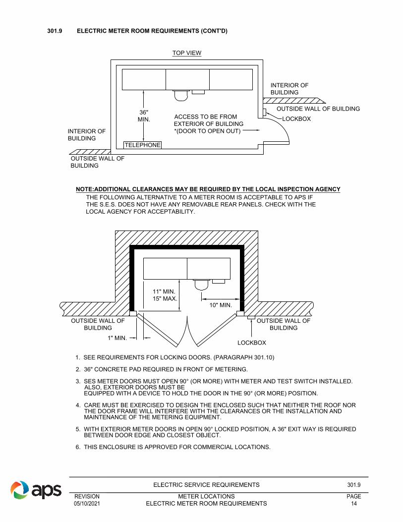
NOTE:ADDITIONAL CLEARANCES MAY BE REQUIRED BY THE LOCAL INSPECTION AGENCY
THE FOLLOWING ALTERNATIVE TO A METER ROOM IS ACCEPTABLE TO APS IF
THE S.E.S. DOES NOT HAVE ANY REMOVABLE REAR PANELS. CHECK WITH THE
LOCAL AGENCY FOR ACCEPTABILITY.
OUTSIDE WALL OF
BUILDING
OUTSIDE WALL OF
BUILDING
LOCKBOX
1" MIN.
1. SEE REQUIREMENTS FOR LOCKING DOORS. (PARAGRAPH 301.10)
2. 36" CONCRETE PAD REQUIRED IN FRONT OF METERING.
3. SES METER DOORS MUST OPEN 90° (OR MORE) WITH METER AND TEST SWITCH INSTALLED.
ALSO, EXTERIOR DOORS MUST BE
EQUIPPED WITH A DEVICE TO HOLD THE DOOR IN THE 90° (OR MORE) POSITION.
4. CARE MUST BE EXERCISED TO DESIGN THE ENCLOSED SUCH THAT NEITHER THE ROOF NOR
THE DOOR FRAME WILL INTERFERE WITH THE CLEARANCES OR THE INSTALLATION AND
MAINTENANCE OF THE METERING EQUIPMENT.
5. WITH EXTERIOR METER DOORS IN OPEN 90° LOCKED POSITION, A 36" EXIT WAY IS REQUIRED
BETWEEN DOOR EDGE AND CLOSEST OBJECT.
6. THIS ENCLOSURE IS APPROVED FOR COMMERCIAL LOCATIONS.
11" MIN.
15" MAX.
10" MIN.
301.9 ELECTRIC METER ROOM REQUIREMENTS (CONT'D)
REVISIONELECTRIC SERVICE REQUIREMENTS
PAGEELECTRIC METER ROOM REQUIREMENTS 1405/10/2021
METER LOCATIONS301.9

ACCESS COVERS
ELECTRIC
EQUIPMENT
WORK SPACE
ENTRANCE
ELECTRIC
EQUIPMENT
ACCESS COVERS
WORK SPACE
AT LEAST ONE ENTRANCE IS REQUIRED TO PROVIDE ACCESS TO THE WORKING
SPACE AROUND ELECTRIC EQUIPMENT. THE INSTALLATION SHOWN IN THE SKETCH
ON THE RIGHT WOULD NOT BE ACCEPTABLE IF THE ELECTRIC EQUIPMENT WAS A
SWITCHBOARD OR PANELBOARD OVER 6' WIDE AND RATED 1200A OR MORE.
WORK SPACE
ACCESS
PANEL
SWITCHBOARD OR
CONTROL PANEL
1200A OR MORE.
AT LEAST 24" WIDE
6-1/2' HIGH
FOR SWITCHBOARDS AND CONTROL PANELS RATED 1200A OR MORE AND OVER 6'
WIDE, THERE SHALL BE ONE ENTRANCE NOT LESS THAN 24" WIDE AND 6-1/2'
HIGH AT EACH END.
NOT
ACCEPTABLE
ACCESS
PANELS
WORK SPACE
WORK SPACE
ENTRANCE
WORK SPACE
SWITCHBOARD OR
CONTROL PANEL
1200A OR MORE.
AT LEAST 24" WIDE
6-1/2' HIGH
ACCESS
PANEL
OVER 6'
301.9 NATIONAL ELECTRIC CODE REQUIREMENTS
REVISIONELECTRIC SERVICE REQUIREMENTS
PAGEELECTRIC METER ROOM REQUIREMENTS 1505/10/2021
METER LOCATIONS301.9

DOUBLE WORK SPACE
ACCESS
PANEL
SWITCHBOARD OR
CONTROL PANEL
1200A OR MORE.
ACCESS
PANEL
OVER 6'
ONLY ONE
ENTRANCE
REQUIRED
EXCEPTION #1: WHERE THE EQUIPMENT LOCATION PERMITS A
CONTINUOUS AND UNOBSTRUCTED WAY OF EXIT TRAVEL.
ALTERNATE
ENTRANCE
LOCATION
ALTERNATE
ENTRANCE
LOCATION
ONLY ONE
ENTRANCE
REQUIRED
SWITCHBOARD OR
CONTROL PANEL
1200A OR MORE.
CONTINUOUS AND
UNOBSTRUCTED WAY
OF EXIT TRAVEL
OVER 6'
EXCEPTION #1: WHERE THE EQUIPMENT LOCATION PERMITS A
CONTINUOUS AND UNOBSTRUCTED WAY OF EXIT TRAVEL.
EXCEPTION #2: WHERE THE WORK SPACE REQUIRED BY
SECTION 110-16(A) IS DOUBLED.
EXCEPTION #2: WHERE THE WORK SPACE REQUIRED BY
SECTION 110-16(A) IS DOUBLED.
301.9 NATIONAL ELECTRIC CODE REQUIREMENTS
REVISIONELECTRIC SERVICE REQUIREMENTS
PAGEELECTRIC METER ROOM REQUIREMENTS 1605/10/2021
METER LOCATIONS301.9

301.9-1 UNACCEPTABLE EQUIPMENT IN METER ROOMS
Equipment not permitted within the electric meter room includes, but is not limited to following:
1. Gas equipment – including piping.
2. Water heaters/boilers – including piping.
3. Mechanical equipment – including motor/generator sets.
4. Batteries and battery charging equipment.
5. Fire risers.
________________________________________________________________________________________________
301.9-2 METER ROOM VENTILATION
Meter room shall have at least two 10” X 10” air vents. Vent locations shall be designed to provide maximum
separation, with one vent located high and the other vent located low.
Meter room containing any electrical equipment that produces heat such as a dry type transformer shall
require the room air temperature to be maintained at maximum of 95º F.
________________________________________________________________________________________________
301.10 LOCK BOX LOCATION
The customer may place a meter room door key in an APS acceptable lock box installed on or within 36” of
the door. The minimum height shall be 36” and the maximum height 60”. The meter room key shall not unlock
any other door on the premises.
REVISIONELECTRIC SERVICE REQUIREMENTS
PAGEMETER ROOMS/LOCK BOXES/METER ENCLOSURES 1705/10/2021
METER LOCATIONS301.9-1

T
TV
11" MIN. AND 15" MAX.
CLEARANCE FROM FRONT OF METER
PANEL TO INSIDE OF CLOSET DOOR.
10" MIN. FROM NEAREST CORNER
OF OTHER CONSTRUCTION.
24" MAX. AND 9" MIN. TO ANY
OVERHEAD OBSTRUCTION.
75" MAX. AND 36"
MIN.
NO LOCKING DEVICES ON THE
ENCLOSURE DOOR.
DOOR MUST OPEN A MIN. OF 90°
AND BE EQUIPPED WITH A DEVICE
TO HOLD THE DOOR IN THE OPEN
POSITION.
36" MIN. WORK SPACE FROM
FRONT OF METER PANEL AND 78"
FROM GROUND TO TOP OF
ENCLOSURE. SEE NOTE 4.
36" MIN.
10" MIN.
FOUNDATION
OUTSIDE WALL OF
RESIDENCE
36" MIN.
11" MIN.
15" MAX.
NOTES:
1. THIS ENCLOSURE IS APPROVED FOR:
A. SINGLE FAMILY SELF-CONTAINED USE ONLY.
B. COMMUNICATION EQUIPMENT
C. CATV
2. THIS ENCLOSURE IS NOT APPROVED FOR:
A. GAS SERVICE OR PIPING
B. WATER SERVICE OR PIPING
C. STORAGE OF ANY KIND
3. THE STRUCTURE FOUNDATION SHALL NOT
EXTEND INTO OR UNDER THE METER CLOSET.
4. CLEAR AND LEVEL WORK SPACE SHALL BE PROVIDED
PER PARAGRAPH 301.6, NOTES 8, 9, 10 AND 301.7.
5. METER CLOSET DOOR SHALL BE IDENTIFIED WITH A
PERMANENT TAG SHOWING "ELECTRIC METER",
MANUFACTURE PER 302.1
6. POCKET DOORS ARE ACCEPTABLE.
36" MIN.
301.11 RESIDENTIAL ELECTRIC METER CLOSET REQUIREMENTS - SELF CONTAINED
REVISIONELECTRIC SERVICE REQUIREMENTS
PAGERECESSED RESIDENTIAL METERING REQUIREMENTS 1805/10/2021
301.11

NOTES:
1) DOOR
A) MUST BE THE WIDTH AND HEIGHT OF THE CLOSET
B) OPEN 90° WITH DEVICE TO HOLD DOOR IN OPEN POSITION
C) HANDLE CAN NOT BE LOCKABLE
2) THIS ENCLOSURE APPROVED FOR:
A) SINGLE FAMILY
B) COMMUNICATIONS EQUIPMENT
C) CATV
3) THIS ENCLOSURE NOT APPROVED FOR:
A) GAS PIPING
B) WATER SERVICE OR PIPING
C) STORAGE OF ANY KIND
4) THE STRUCTURE FOUNDATION SHALL NOT EXTEND INTO
OR UNDER THE METER CLOSET.
5) CLEAR AND LEVEL WORK SPACE PER 301.6 NOTES 8, 9, 10,
AND 301.7.
6) METER CLOSET DOOR SHALL BE IDENTIFIED WITH A
PERMANENT TAG SHOWING "ELECTRIC METER"
MANUFACTURE PER 302.1
4"
MIN.
24" MIN.
75" MAX.
36" MIN.
10" MAX.
15" MIN.
OUTSIDE WALL OF
RESIDENCE
36" MIN.
FOUNDATION
4"
MIN.
36" MIN.
10" MIN.
10" MIN.
36" MIN.
301.11-1 RESIDENTIAL ELECTRIC METER CLOSET REQUIREMENTS - 400 AMPS & LARGER
REVISIONELECTRIC SERVICE REQUIREMENTS
PAGERECESSED RESIDENTIAL METERING REQUIREMENTS 1905/10/2021
301.11-1

MAIN/
DISTRIBUTION
SECTION
PULL
SECTION
SEALABLE
FROM
FRONT
BUILDING
WALL
PLASTER RING
FINISH GRADE
SEE NOTE 1
24"
NOTES:
1. SEE SECTION 500 FOR UNDERGROUND CONDUIT AND RISER REQUIREMENTS.
2. SEE SECTION 1100, DRAWING 301 FOR METER CAN REQUIREMENTS.
301.12 MAIN SWITCH LOCATION
The meter and service main switch shall be installed on the same wall adjacent to each other and accessible
from the same working area. Exception Fire Pump disconnects may be located at the fire pump control panel.
(See Paragraph 302.3 Main Switch).
________________________________________________________________________________________________
301.13 METER AND MAIN SWITCH SEQUENCE
Meters and metering equipment for services of 0 - 600 volts shall be located ahead, or on the supply side, of
the customer’s main service entrance switch. Exception to this sequence is permissible only when required
by electrical codes.
When a single set of service entrance conductors supply a multi-meter installation, numbering from two to six
meters, a main switch for each meter shall be located on the load side of each meter.
For multi-meter installations, numbering seven or more meters connected to a single set of service entrance
conductors, NEC 230-71 requires the installation of a main service switch located on the supply side of the
group of meters (Its access door shall be under APS lock and seal). In these instances, an individual main
switch must also be installed on the load side of each meter.
APS shall not allow a main service disconnect ahead of less than seven meters in or on a separate
enclosure or switchboard.
________________________________________________________________________________________________
301.14 TYPICAL SEMI-FLUSH INSTALLATION
REVISIONELECTRIC SERVICE REQUIREMENTS
PAGEMAIN SWITCH LOCATION 2005/10/2021
301.12

R
GAS
GAS
36 INCH
RADIAL CLEARANCE
FROM VENTING SIDE
OF REGULATOR
36''
STUB-OUT
C
L
48 '' MIN
75 '' MAX
MIN
HO
US
E
AREA INSIDE OF BOX
TO REMAIN CLEAR
OF ALL ELECTRICAL
EQUIPMENT. AREA
EXTENDS THE FULL
WIDTH OF THE GAS
METER ASSEMBLY
AREA INSIDE OF BOX TO REMAIN
CLEAR OF ALL ELECTRICAL
EQUIPMENT. AREA EXTENDS THE FULL
WIDTH OF GAS METER ASSEMBLY
FRONT VIEW SIDE VIEW
90 ''
FIGURE 1
301.15 ELECTRIC METER SEPARATION BETWEEN WATER, GAS METER, AND FUEL SOURCES
301.15-1 ELECTRIC, WATER AND GAS METER SEPARATION (FIGURE 1)
1. Size and dimensions of panels will vary.
2. Working clearance shall be a minimum of 36 inches wide in front of meter panel. If electric panels extend
wider that the 36 inch minimum, the working clearance shall be the width of the entire assembly. Working
space shall extend out from the face of the electric meter panel a minimum of 36 inches. See paragraph
301.7 for additional workspace requirements.
3. Area directly above gas meter shall remain clear of any electrical equipment.
4. For conduit system and riser requirements, refer to Section 500.
5. For Trenching Requirements, refer to Section 600.
6. Gas piping (above grade) may be located below electric panel(s), but shall not include any couplings in
that area.
7. APS prohibits water valves or hose bibs to be located within the 36 inch by 36 inch safe work area in front
of the electric panels. This is to prevent any grounded surfaces in the work area and to ensure the
standing surfaces remain safe and dry.
8. Drain pipes or soffits are prohibited above the meter enclosures to ensure the work area standing surfaces
remain safe and dry.
REVISIONELECTRIC SERVICE REQUIREMENTS
PAGEELECTRIC AND GAS METER SEPARATION 2105/10/2021
MAIN LOCATION301.15

CC
LL
48 '' MIN
75 '' MAX
48 '' MIN
75 '' MAX
AREA INSIDE OF BOX TO REMAIN
CLEAR OF ALL ELECTRICAL
EQUIPMENT. AREA EXTENDS THE FULL
WIDTH OF GAS METER ASSEMBLY
24 '' MIN 48 '' MIN 18 '' MIN
FIGURE 2
SEE NOTE 4
GAS
STUB-OUT
VALVE
301.15 ELECTRIC METER SEPARATION BETWEEN WATER, GAS METER, AND FUEL SOURCES
301.15-2 ESTABLISHING GAS CLEARANCES DURING CONSTRUCTION (FIGURE 2)
1. Measure the minimum horizontal separation from the edge of the electric meter panel to the closest point
of the gas service (if known), or from the electrical UG riser pre-construction “Stub-Up” to the gas service
“Stub-Out” on the house (Preferred Method).
2. Size and dimensions of panels will vary.
3. See paragraph 301.15-1 for additional requirements.
4. 48 inch dimension is required based upon typical gas meter dimensions and layout. The intent is to
maintain a 36 inch radial clearance (see figure 1 in 301.15-1) from the venting side of the regulator to the
closest corner of the electric panel. If the location does not provide 48 inches, contact the gas company to
explore options for maintaining the 36 inch radial clearance that is required.
REVISIONELECTRIC SERVICE REQUIREMENTS
PAGEELECTRIC AND GAS METER SEPARATION 2205/10/2021
MAIN LOCATION301.15

C
L
10 FT MIN
20 FT MIN
48 '' MIN
75 '' MAX
MY
FUEL
COMPANY
PERMANENT FUEL TANK
(FILLED ON-SITE)
50
APS
FIGURE 3
C
L
5 FT MIN
20 FT MIN
48 '' MIN
75 '' MAX
50
APS
PROPANE
GAS
PORTABLE FUEL TANK
FIGURE 4
301.15-3
VENT
PERMANENT OR PORTABLE GENERATOR
(COULD BE FILLED ON-SITE)
NOTE 2
PROPANE
GAS
PORTABLE FUEL TANK
(FILLED ON-SITE)
(FILLED OFF-SITE ONLY)
VENT
1. THE 10' CLEARANCE SHALL BE BETWEEN THE ELECTRICAL
PANEL WORKING SPACE AND THE PERMANENT/PORTABLE
GENERATOR OR FUEL TANKS.
2. GENERATOR SHALL NOT OBSTRUCT EQUIPMENT ACCESS.
NOTES:
VENT
APS
PAD-MOUNTED
FACILITY
APS
PAD-MOUNTED
FACILITY
301.15 ELECTRIC METER SEPARATION BETWEEN WATER, GAS METER, AND FUEL SOURCES
REVISIONELECTRIC SERVICE REQUIREMENTS
PAGEELECTRIC AND GAS METER SEPARATION 2301/27/2022
MAIN LOCATION301.15
A minimum 20-foot separation / clearance is required between APS electrical facilities in outdoor locations
where fire or explosion hazards may exist and the following:.
GASOLINE DIESEL FUEL
COMPRESSED NATURAL GAS (CNG) LIQUEFIED NATURAL GAS (LNG)
LIQUEFIED PETROLEUM GAS (LPG) HYDROGEN IN A GASEOUS FORM (GH2)
HYDROGEN IN A LIQUID FORM (LH2)
If the minimum 20-foot separation cannot be maintained, a fire barrier / fire wall shall be installed between the
pad-mounted facility and the generator.
The fire barrier / fire wall shall have a minimum 2-hour fire rating. The fire wall height shall extend at least
1-foot above the line of sight between any point on the top of the pad-mounted facility and any point on the
top of the generator. The fire wall shall also extend at least 2-feet horizontally beyond the line of sight
between any point of the pad-mounted facility and any point of the generator. A minimum of 3-feet separation
shall be maintained between the fire wall and side of APS pad-mounted facility except from the side of certain
facilities (e.g., automatic transfer switch, supervisory switches) containing control features where a 6-foot
separation shall be maintained. See FIGURES 5 AND 6 for illustration.

FUELTANK
GENE
RATO
R
FINISHEDGRADE
LINESIGHT
2-HRFIREWALL
1'
3'
FIGURE 5 - FIRE WALL HEIGHT (PROFILE VIEW)
GENE
RATO
R
LINESIGHT
2'
2'LINESIGHT
MIN.
FIGURE 6 - FIRE WALL LENGTH (PLAN VIEW)
MIN.
3'
AHJ ***VARIES BY
***BY AHJVARIES
APSPAD-MOUNTEDFACILITY
APSPAD-MOUNTEDFACILITY
301.16 ROLL-UP DOORS
Aluminum Roll-up doors used in conjunction with enclosed meter rooms are to be constructed utilizing
minimum 22-gauge slats. Dimensions of roll-up door must provide for a minimum clearance of 12” in width
and height greater than the largest piece of equipment being located within the meter room. This is to provide
for ease of installation and removal.
Door must be equipped with bottom and guide weather stripping.
A minimum clearance of 12” is required between the face of the service entrance equipment and the door.
The door may be operated either mechanically or electronically. Manual push-up doors are not permitted.
If the door is mechanically operated, the door must be equipped with an indoor mounted chain hoist with a
maximum allowable pull tension of ten pounds. A minimum working clearance of 36” square must be provided
adjacent to the chain hoist to provide for safe operation.
Room must be equipped with light.
If the door is electrically operated it must have an emergency release device.
Chain hoist and/or electrical control switch for the door must be located so that the door may be operated
without the need to cross in front of the SES to operate.
APS lock box to be installed in close proximity to main entry door to meter room.
Owner is responsible for the on-going maintenance to insure continuous proper operation of the door.
REVISIONELECTRIC SERVICE REQUIREMENTS
PAGEROLL-UP DOORS 2401/27/2022MAIN LOCATION
301.15
301.15 ELECTRIC METER SEPARATION BETWEEN WATER, GAS METER, AND FUEL SOURCES
Where the degree of hazard is unknown, Contact APS Representative for proper classification of the
hazardous locations. Aluminum Roll-up doors used in conjunction with enclosed meter rooms are to be
constructed utilizing minimum 22-gauge slats. Dimensions of roll-up door must provide for a minimum
clearance of 12” in width and height greater than the largest piece of equipment being located within the
meter room. This is to provide for ease of installation and removal.
MINIMUM CLEARANCES
PAD USAGE (TYPICAL) PAD DIMENSIONTO
BUILDINGSTO
FENCESTO
COMM. PED
A B C C D1Ø LOW PROFILE TRANSFORMER 25-50KVA 42" 42"
24" 24"
12"1Ø LOW PROFILE TRANSFORMER 75-167KVA 42" 48"1Ø BOX PAD INSTALLATION 57" 57"
3Ø TWO TRANSFORMER BANK 90" 48"24"3Ø 75-750KVA TRANSFORMER 88" 75"
3Ø 1000-2500KVA TRANSFORMER 102" 100"

SUITE 102
1/4" MIN.
APT 201
1/4" MIN.
302.0 SPECIAL CONSIDERATIONS
________________________________________________________________________________________________
302.1 METER IDENTIFICATION BY CUSTOMER
Where the installation requires more than one meter for service to the premises, then each meter socket and
corresponding disconnect shall be permanently (not painted) marked by the customer to properly identify the
portion of the premises being served.
When adding a new meter to an existing service location, all meters and corresponding disconnects shall be
labeled to properly identify the portion of the premises being served by each meter and corresponding
disconnect.
The identification shall be the same as the apartment, townhouse, office, suite, trailer, R.V. space, etc.,
actually served through the socket and the corresponding disconnect. The identifying marking placed on each
meter panel shall be impressed into or raised from a tag of aluminum, brass or other approved non-ferrous
metal with minimum 1/4" high letters. The tag shall be riveted to the meter socket panel and corresponding
disconnect.
If meters are located in a meter room or cabinet, micarda tags are acceptable. Tags will be black with white
letters Minimum 1/4“ high letters. Micarda tags shall be riveted to the meter panel. These requirements are
intended to prevent the identification(s) from being obscured by painting of the building and attached service
equipment.
The Company’s meter department may require the assistance of the Customer prior to the setting of the
meters in a multi-metered development in order to verify that each meter socket identification coincides with
the apartment, townhouse, office, suite, trailer, R.V. space, etc. actually served through the socket.
________________________________________________________________________________________________
302.1-1 SERVICE IDENTIFICATION
All equipment shall be permanently labeled for the specific voltage and current being served.
________________________________________________________________________________________________
302.2 METER HEIGHT
The requirements for meter height, which is the vertical distance between the center line of the meter and the
standing surface, shall be as follows:
1. When meters are located in a meter room or enclosed cabinet. 36" min. 75" max.
2. When meters are wall, semi-flush, pedestal, or surface mounted outdoors, but not located in a meter room
or enclosed cabinet. 48" min. 75" max.
________________________________________________________________________________________________
302.3 MAIN SWITCH
For each meter installed on a service, the contractor/customer, in compliance with applicable codes, shall
furnish and install a fusible switch, a circuit breaker, or other approved disconnecting means which shall
control all of and only the energy registered by that meter. The disconnecting means, where permitted by the
governing code or ordinance, may consist of a group of fusible switches or circuit breakers. These fuses or
circuit breakers must be lockable and designed to interrupt and withstand the available fault current. (See
Paragraph 301.13 Main Switch Locations).
In cases where residential all-in-one meter panels are installed with multiple positions for main disconnects,
APS requires all positions to be filled with disconnects that are designed to interrupt and withstand the
available fault current.
REVISIONELECTRIC SERVICE REQUIREMENTS
PAGESPECIAL CONSIDERATIONS 2505/10/2021
302.0

REVISIONELECTRIC SERVICE REQUIREMENTS
PAGESPECIAL CONSIDERATIONS 2601/27/2022
302.3-1
302.3-1 MULTIPLE SERVICE DISCONNECTS (TWO TO SIX):
Code and Standards: NEC - Article 230.90(A), Exception No. 3
UL 891 - Table 26 and Section8.8.1.6.13
Using the Codes and Standards: NEC and UL 891 establish the rules for multiple service disconnects in
dead-front switchboard. The following requirements shall be met:
1. Client provides calculations showing that the load does not exceed the sum of the ratings of
service disconnects.
2. If the sum of the service disconnects does not exceed the service rating, then the installation is
code compliant.
3. However, if the sum of the service disconnects exceeds the service rating, then Exception No. 3
in NEC 230.90 (A) can be used. To apply this exception, provide calculations showing a value
below the service rating by utilizing the diversity factors from UL 891 Table 26 shown below.
Note: Exceeding the current rating of the SES after applying the factors in Table 26 of UL 891 will result in a
violation of NEC110.3(B).
Exception: A UL891 switchboard that has been listed, and marked as "Solar Ready" would have a
dedicated disconnect for a photovoltaic back-feed. In this case the disconnect can be excluded from the
sum of disconnects. A permanent warning label shall be affixed by the manufacturer next to the
disconnect indicating its purpose and that no loads are to be connected.
Application Examples:
§ Specification: 600A SES, with (6) 200A service disconnects
The sum of the disconnects is 1200A. Apply the 70% factor from Table 26.
(1200A X .7 = 840A > 600 A) - NOT APPROVED!
§ Specification: 600A SES, with (2) 200A & (4) 100A service disconnects
The sum of the disconnects is 800A. Apply the 70% factor from Table 26.
(800A X .7 = 560A < 600A) - APPROVED!
§ Preserving Utility Service Integrity: A separate but related issue arises in
cases where a fusible disconnect configuration can physically accommodate a
larger fuse ampacity than originally calculated using table 26. Mandating that
the fusible disconnect configuration does not have the ability to accommodate
a larger fuse ampacity will ensure that the potential for future load additions
are limited to the rating of the utility equipment and SES.
Diversity Factors from UL 891, Table 26
# Service Disconnects Factor (%)
1 100
2 - 3 80
4 - 6 70

302.4 FOREIGN DEVICES IN SEALABLE CABINETS
No devices by the Customer shall be installed in or attached to the meter, meter socket, meter cabinet or the
metering compartment and pull section area of a service entrance section. Emergency power transfer switches,
energy devices, over-current devices, etc., shall be located on the load side and exterior to these metering
components.
________________________________________________________________________________________________
302.5 METER SOCKET ENCLOSURES
All socket enclosures shall be of the ring type. The meter socket shall be securely mounted so that its meter
jaws are in true horizontal and vertical planes, and will support the meter without tilt in any direction. Gutter
connectors (of the Chase nipple-sleeve type) shall not be used on unfused gutters.
Meter enclosures and pull sections shall not be used as junction boxes, raceways, or wireways.
________________________________________________________________________________________________
302.6 PROPER INSTALLATION OF COUPLINGS AND GUTTERS
When entering or leaving service entrance enclosure, an approved method shall be used. Burning of holes in
the enclosure or the welding of couplings or fittings in lieu of an approved hub is not permitted or acceptable.
________________________________________________________________________________________________
302.7 TERMINATIONS OR LUGS FURNISHED BY APS (Underground)
APS shall furnish and install compression terminations for connecting APS service conductors to the bus bar in
service entrance sections, 400 amp wall hung cabinets and pull boxes with cable terminating facilities when
served from underground. See EUSERC DWG #347 in Section 1100 for termination bolt requirements. 200
amps and less - use mechanical terminals supplied by the customer.
________________________________________________________________________________________________
302.8 SECURED IN PLACE (S.E.S.)
All service entrance sections shall be securely fastened to the surface on which it is mounted. Wooden plugs
driven into holes in masonry, concrete, plaster, or similar material shall not be used.
________________________________________________________________________________________________
302.9 REQUIRED APPROVAL FOR METERING IN SERVICE EQUIPMENT
Customer shall select from the pre-approved list for all single-phase residential self-contained services. If it is on
the pre-approved list, then it is approved for that type of residential service only. If it is not on the list, then it is
not approved to be used in APS service territory for self-contained services. Commercial sites require meter
enclosures with EUSERC approved test blocks/bypass provisions for all self-contained services 200 Amps and
below. All commercial sites above 200 Amps are required to have EUSERC approved CT rated meter
enclosures. The following meter enclosures shall be submitted through an APS Representative for review and
approval prior to manufacturing of the equipment: residential multi-meter packs not listed on the APS
pre-approved list; residential CT rated enclosures; and all commercial meter enclosures. Customer shall
coordinate through the APS Control Desk @ APS Contact Map for new service or service upgrades (also see
ESRM 200.2-1 and 200.2-2).
Drawing submittal shall include: engineering and manufacturer one-lines showing location of neutral to ground
bond link and neutral disconnecting means, switchboard manufacturer (name), EUSERC page references that
are applicable, ampacity of switchboard, physical dimensions, voltage, phase, bus bracing (AIC rating), how
many service disconnects (which all are required to have padlockable provisions), accurate address (street and
number), etc.
In addition to the above equipment submittal requirements, a separate application is required for review and
approval when this equipment includes any connections or provisions for any existing or proposed inverters or
generators. Contact an APS Representative and review the guides and resources available @ APS
Interconnection page. Begin the APS Interconnection Application Process @ APS PowerClerk login. Refer to
ESRM 104.11 – 104.12-2 for additional information on backup generation.
REVISIONELECTRIC SERVICE REQUIREMENTS
PAGESPECIAL CONSIDERATIONS 2701/27/2022
302.4

302.10 EUSERC - ELECTRIC UTILITY SERVICE EQUIPMENT REQUIREMENTS COMMITTEE
Switchboard service sections and bus duct risers approved for use in the area served by APS are built to the
standards developed by the Electric Utility Service Equipment Requirements Committee, and are available to
the customer through electric wholesale distributors (See Section 1100).
________________________________________________________________________________________________
302.11 SERVICE ENTRANCE SECTION
A standard service entrance section is a free-standing piece of equipment which contains bussing for the
termination of service entrance conductors, bussing for the connection and mounting of current transformers,
panels for the installation of the test switch and meter socket, a service main disconnect switch or breaker,
and in many cases, distribution feeder breakers or switches.
The standard service entrance section is usually built to serve the Customer with heavy electrical supply
needs, and is available with service main switch or breaker ratings from 200 amperes through 3000 amperes.
For sections above 3000 amperes consult APS.
Standards for service entrance section have also been developed for self-contained meters, both residential
and non-residential, and with either standard duty or heavy-duty sockets. This equipment is built on special
order to meet the needs of the Customer’s service.
________________________________________________________________________________________________
302.12 OVERHEAD RISER AND BUS DUCT RISER REQUIREMENTS
Maximum number of conductors per phase shall be two (2); all service entrance conductor requirements
exceeding 2-750 MCM conductors per phase shall be bus bar construction. All bus bar cabinets shall be
constructed in accordance with Electric Utility Service Equipment Requirements (EUSERC). For address of
Electric Meter Section, see Paragraph 302.9. For bus-way service head requirements, see EUSERC DWG.
349 in Section 1100. (See also Section 400, paragraph 400.3). The customer shall submit drawings and
information to APS for review and approval in accordance with the submittal requirements described in ESRM
302.9.
________________________________________________________________________________________________
302.13 (RESERVED)
________________________________________________________________________________________________
302.14 METER TYPES USED ON APS SYSTEM
Direct Access meters shall have a visual kWh display and must have a physical interface to enable site
interrogation of all stored meter data. All meters installed must support the Customer’s APS rate tariff.
FORM NUMBERS DESCRIPTION
1S Single phase, 2 wire, Self-contained
2S Single phase, 3 wire, Self-contained
3S Single phase, 2 wire, 5 terminal, Transformer rated
5S* Single phase, 3 wire, 6 terminal, Transformer rated
5S Three phase, 3 wire, 8 terminal, Transformer rated
6S Three phase, 4 wire Wye, 2 1/2 element, Transformer rated
8S Three phase, 4 wire Delta, Transformer rated
9S Three phase, 4 wire Wye, 13 terminal, Transformer rated
12S Network, Three phase, 3 wire, 5 terminal, Self-contained
14S Three phase, 4 wire Wye, 2 1/2 element, Self-contained
15S Three phase, 4 wire Delta, Self-contained
16S Three phase, 4 wire Wye, 3 element, Self-contained
* = 5S for new installations - 4S for Maintenance Only
REVISIONELECTRIC SERVICE REQUIREMENTS
PAGESPECIAL CONSIDERATIONS 2803/06/2022
302.10

303.0 SELF CONTAINED METERING
________________________________________________________________________________________________
303.1 EQUIPMENT FURNISHED AND INSTALLED BY APS - STANDARD OFFER CUSTOMERS ONLY
1. All meters and metering equipment required for billing purposes.
2. Sealing rings and seals.
________________________________________________________________________________________________
303.2 EQUIPMENT FURNISHED AND INSTALLED BY THE CUSTOMER
1. Meter sockets.
2. Multiple meter panels and prefabricated panels.
3. Meter enclosures.
4. Service entrance switchboards.
5. Safety test blocks.
6. Proper bonding and grounding.
________________________________________________________________________________________________
303.3 SELF-CONTAINED SOCKET RATINGS
TYPE OF SERVICE SIZE OF SERVICE ENTRANCE SOCKET RATINGS
Residential
All sockets shall have a maximum ampere rating not less than the
ampacity of the main service switch (Maximum ampere rating of
socket being 125% of continuous duty rating).
Non-residential & Industrial
Up to 100 amp 100 amp Continuous
Non-residential & Industrial
101-200 amp 200 amp Continuous
Irrigation (277/480) Up to 100 amp (Up to & including 75 HP) 100 amp Continuous
Irrigation (277/480) 101-200 amp (Up to & including 75 HP) 200 amp Continuous
In addition, self-contained sockets shall conform to the following requirements:
1. Dimensions and construction for sockets and enclosures shall comply with ANSI C12.7 standard for
watt-hour meters, and UL 414 standard.
2. Line and load terminals shall be compatible with either copper or aluminum wire.
3. Terminals shall be of sufficient size as to permit insertion of maximum specified wire without removing any
strands.
4. The socket jaw or clip shall be of beryllium copper alloy or equivalent.
5. The socket jaw or clips shall be clean. Foreign material (such as paint, mud, etc.) shall be removed by
customer prior to APS installing service or meter.
________________________________________________________________________________________________
303.4 SOCKET ENCLOSURES
All socket enclosures shall be of the “ring-type.”
________________________________________________________________________________________________
303.5 METER SOCKET CLOSING DEVICES
Meter sockets shall not be equipped with circuit closing or bypass devices which automatically close when
the meter is removed from the socket.
REVISIONELECTRIC SERVICE REQUIREMENTS
PAGESELF CONTAINED METERING 2903/06/2022
303.0

303.6 SAFETY TEST BLOCKS
APS RESERVES THE RIGHT TO REQUIRE SAFETY TEST BLOCKS BE INSTALLED IN THE EVENT AN
EXISTING SERVICE NO LONGER MEETS THE FOLLOWING REQUIREMENTS.
________________________________________________________________________________________________
303.6-1 SINGLE-PHASE SAFETY TEST BLOCK INSTALLATIONS
All single-phase non-residential services with self-contained meter installations shall require safety test blocks
be furnished by the Customer. Reference Section 1100, Drawings 304,305 and 306.
Locations where safety test blocks are not required:
1. House meters on residential apartment complexes.
2. Non-computerized sign boards.
3. Sprinkler controls.
4. Single-phase temporary construction services (when 400Amps are needed a CT-Current Transformer
rated panel will be required).
5. Parking lot lighting services.
6. Barns.
7. Domestic wells serving individual or multifamily water supply so long as they are not a water company.
8. Residential hobby shops.
9. CATV rectifiers and dryers.
10. Gas Company cathodic protection sites.
11. Non-computerized gates to residential communities.
12. Generating Facility (GF) Production Metering (see 303.6-3 for additional details).
________________________________________________________________________________________________
303.6-2 THREE-PHASE SAFETY TEST BLOCK INSTALLATIONS
Safety test blocks shall be required on all three-phase self-contained installations except for
Generating Facility (GF) Production Metering as noted in section 303.6-3.
________________________________________________________________________________________________
303.6-3 GENERATING FACILITY (GF) PRODUCTION METERING APPLICATIONS
Safety Test Blocks are not required to be installed at Customer Installed Production Metering specified in
Section 9.0 (“Metering Requirements”) of the APS document entitled “Interconnection Requirements for
Distributed Generation” for Customer Owned Generation (Reference section 104.11). The Customer shall
install an isolation device(s) (i.e. Utility Disconnect Switch (on the Line side of the Production Meter to
isolate/remove all voltage and current from the meter. This isolation device shall meet all the requirements of
Section 8.2 (“Disconnect Switch”) of the APS document entitled “Interconnection Requirements for Distributed
Generation.” (Reference Section 104.12.2).
________________________________________________________________________________________________
303.7 HIGH LEG LOCATION (3ø 4W DELTA SERVICE)
Self-contained Meter Sockets: wiring to self-contained meter sockets, whether individual sockets or in multiple
meter panel boards, shall have the power phase or “high leg” to ground, in the right hand socket terminals.
Identification of “high leg” shall be by an outer finish that is orange in color or permanent tagging. This
identification shall be placed at all points where a connection is made or will be made, including leads where
service will be connected. Refer to 304.3 for CT rated equipment.
REVISIONELECTRIC SERVICE REQUIREMENTS
PAGESELF TEST BLOCKS/HIGH LEG LOCATION 3005/10/2021
SELF CONTAINED METERING303.6

LINE
NEUTRAL
LOAD
120V - 1Ø - 2 WIRE
FIG 1
LINE
LOAD
120/240 - 1Ø - 3 WIRE
FIG 2
NEUTRAL
LINE
LOAD
NEUTRAL
TOP TERMINAL
BOTTOM TERMINAL
SEE NOTE 4
120/208V - 1Ø - 3 WIRE WYE
FIG 3
LINE
LOAD
240V - 3Ø - 3 WIRE Δ
FIG 4
OBSOLETE
FOR
MAINTENANCE
ONLY
LINE
LOAD
480V - 3Ø - 3 WIRE Δ
FIG 5
LINE
NEUTRAL
LOAD
120/240V - 3Ø - 4 WIRE Δ
FIG 6
POWER
LEG
NEUTRAL
LINE
LOAD
120/208V - 3Ø - 4 WIRE WYE
277/480V - 3Ø - 4 WIRE WYE
FIG 7
1. SOCKETS FOR NON-RESIDENTIAL INSTALLATIONS SHALL BE EQUIPPED WITH
TEST-BYPASS FACILITIES WHEN REQUIRED BY THE SERVING AGENCY.
2. LINE CONDUCTORS SHALL BE CONNECTED TO THE TOP TERMINALS OF SOCKET AND
LOAD CONDUCTORS CONNECTED TO THE BOTTOM TERMINALS OF THE SOCKET.
3. POTENTIAL TAPS, INCLUDING THE NEUTRAL TAP, SHALL BE LOCATED BEHIND SEALED
PANELS.
4. CLAMPED OR BOLTED CONNECTIONS IN METERING EQUIPMENT ENCLOSURES SHALL
BE PERMITTED, INCLUDING THE NEUTRAL CONNECTION.
5. SEE PARAGRAPH 304.2-1 FOR CT METER SOCKETS
FRONT VIEWS SHOWN
EUSERC DWG #G1
NOTES:
303.8 CONNECTION DIAGRAM FOR SELF CONTAINED METER SOCKETS - DWG #G1
REVISIONELECTRIC SERVICE REQUIREMENTS
PAGE CONNECTION DIAGRAM FOR SALE CONTAINED METER SOCKET-DWG #G13105/10/2021
INSTALLATION GUIDE DRAWING303.8

TBF TBFTBFTBF
FIG. 1
COMMERCIAL
FIG. 2
RESIDENTIAL
FIG. 3
RESIDENTIAL
FIG. 4
RESIDENTIAL
OVERHEAD INSTALLATIONS
TBF TBF TBF TBF
FIG. 5
RESIDENTIAL
FIG. 6
COMMERCIAL
FIG. 7
RESIDENTIAL
UNDERGROUND INSTALLATIONS
TBF = TEST BLOCK FACILITIES
EUSERC DWG #G2
303.9 INSTALLATION GUIDE DRAWING TYPICAL MULTI-METERING ARRANGMENTS - DWG #G2
REVISIONELECTRIC SERVICE REQUIREMENTS
PAGETYPICAL MULTI-METER ARRANGEMENT - DWG #2 3205/10/2021
INSTALLATION GUIDE DRAWING303.9

CUSTOMER'S SERVICE
ENTRANCE CONDUCTORS
BARRIER
CABLE PULLING
SECTION SEE
DWG 343.
MAIN DISCONNECT
SWITCH
TBF
HOUSE
METER
FIG. 1 TYPICAL COMBINATION SERVICE TERMINATION ENCLOSURE
AND METER SOCKET PANELS FOR MULTI-UNIT RESIDENTIAL USE.
MAIN
DISCONNECT
COMPARTMENT
TEST BYPASS FACILITIES
(HOUSE METER ONLY)
CABLE
PULLING
SECTION SEE
DWG 343.
SEALABLE GUTTER
TBF TBF TBF
TEST
BYPASS
FACILITIES
TEST BYPASS
FACILITIES
ENCLOSURE PER
DWGS. 304 & 305.
INCOMING UNDERGROUND
SERVICE CABLE
TEST
BYPASS
FACILITIES
BARRIER
CUSTOMER'S
DISTRIBUTIONS
SECTION
EUSERC DWG #G3
BARRIER
FIG. 2 TYPICAL SERVICE TERMINATION ENCLOSURE
COMBINATION METER SOCKET PANEL
COMMERCIAL USE.
CABLE PULLING
SECTION SEE
DWG 343.
BARRIER
303.10 INSTALLATION GUIDE DRAWING TYPICAL UNDERGROUND SERVICE TERMINATION
ARRANGMENTS - DWG #G3
REVISIONELECTRIC SERVICE REQUIREMENTS
PAGE TYPICAL UNDERGROUND SERVICE TERMINATION ARRANGEMENT - DWG #33305/10/2021
INSTALLATION GUIDE DRAWING303.10

REMOVED CLOSED CLOSED
LINE RACEWAY (SEALABLE)
NOTE #5
NOTE #14
NOTE #6
OPTIONAL
MAIN MAIN
11" MIN.
NOTE #3
MAIN SWITCH COMPARTMENT TO
BE AT END OPPOSITE OF THE LINE
RACEWAY.
FRONT VIEW
SIDE VIEW
8-1/2" MIN.
10" MIN.
LOCATION
OPTIMAL
TOP OR BOTTOM.
NOTE #4
1. THIS DEVICE MAY BE USED FOR MULTIPLE NON-RESIDENTIAL AND INDUSTRIAL METER
INSTALLATIONS MOUNTED IN A GANGED ARRAY.
2. TEST-BYPASS BLOCKS WITH RIGID INSULATING BARRIERS SHALL BE INSTALLED AND WIRED
OR BUSSED TO A LINE RACEWAY AND ALSO WIRED OR BUSSED TO THE METER SOCKET
THEN TO THE MAIN SWITCH BY THE MANUFACTURER. BLOCKS AND BARRIERS SHALL
CONFORM TO EUSERC DRAWING 312 REQUIREMENTS WITH PHYSICAL ARRANGEMENT
CONFORMING TO DRAWINGS 304 AND 305. CONNECTIONS SEQUENCE IS LINE-LOAD, LINE
LOAD, LINE LOAD FROM LEFT TO RIGHT.
3. MINIMUM ACCESS OPENING TO TEST-BYPASS BLOCK SHALL BE 11' X 10”.
4. THREE INCHES MINIMUM CLEARANCE REQUIRED FOR UTILITY TEST PURPOSES.
5. ALL SECTION COVERS SHALL BE INDEPENDENTLY REMOVABLE. UPPER COVER SHALL BE
NON-REMOVABLE WHEN METER IS IN PLACE. METER SOCKET SHALL BE MOUNTED ON
SUPPORT AND ATTACHED TO PANEL. TEST BY-PASS COVER SHALL BE SEALABLE AND
PERMANENTLY LABELED: “DO NOT BREAK SEAL. NO FUSES INSIDE”.
6. WHEN A NEUTRAL IS REQUIRED FOR METERING OR TESTING, AN INSULATED NEUTRAL
TERMINAL, MOUNTED ON EITHER SIDE, SHALL BE PROVIDED BEHIND EACH TEST-BYPASS
COVER PANEL. THE TERMINAL SHALL BE READILY ACCESSIBLE WHEN THE COVER PANEL IS
REMOVED AND SHALL BE INDIVIDUALLY CONNECTED TO THE NEUTRAL BUS WITH A
MINIMUM OF NO. 8 COPPER WIRE.
7. FOR 3Ø, 4 WIRE. CONNECT 7TH JAW TO BODY OF NEUTRAL LUG WITH NO. 12 MINIMUM
COPPER WIRE.
8. FOR 3Ø, 4 WIRE DELTA, IDENTIFY THE RIGHT HAND TEST-BYPASS BLOCK.
9. FOR 3Ø, 3 WIRE, INSTALL BUS TO CONNECT LINE AND LOAD POLES TOGETHER AT TOP OF
CENTER TEST-BYPASS BLOCK AND CONNECT 5TH JAW TO THIS BUS USING NO. 12 MINIMUM
COPPER WIRE.
10. FOR 1Ø. 3 WIRE, OMIT CENTER TEST-BYPASS BLOCK.
11. FOR 1Ø, 3 WIRE, 120/208 VOLTS, OMIT CENTER TEST-BYPASS BLOCK. CONNECT 5TH JAW
TO BODY OF NEUTRAL LUG WITH NO. 12 MINIMUM COPPER WIRE.
12. PERMANENT LINE-LOAD LABELS ON INSIDE BACK OF ENCLOSURE IN ¾” (MIN.) HIGH
BLOCK LETTERS.
13. MINIMUM DEPTH SHALL BE 4 ½” INCHES FOR 0 - 100 AMPS AND 6 INCHES FOR 101 - 200
AMPS
14. SEE EUSERC DRAWING 343 FOR PULL BOX DETAILS WHEN USED ON UNDERGROUND
SERVICE
EUSERC DWG #G4
ALL DIMENSIONS SHOWN ARE IN INCHES
303.11 SAFETY - SOCKET BOX WITH TEST BY-PASS FACILITIES FOR MULTIPLE SELF-CONTAINED METER
INSTALLATIONS 0 - 200 AMPS, 0 - 600 VOLTS
REVISIONELECTRIC SERVICE REQUIREMENTS
PAGE SELF-CONTAINED METER INSTALLATIONS 0 - 200 AMPS, 0 - 600 VOLTS 3405/10/2021 SAFETY - SOCKET BOX WITH TEST BY-PASS FACILITIES FOR MULTIPLE
303.11
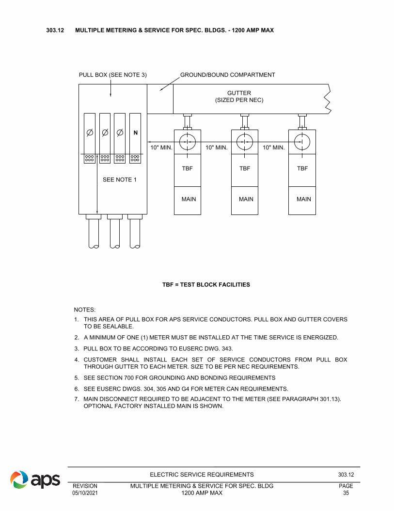
PULL BOX (SEE NOTE 3)
N
SEE NOTE 1
10" MIN. 10" MIN. 10" MIN.
TBF
MAIN
TBF
MAIN
TBF
MAIN
GROUND/BOUND COMPARTMENT
GUTTER
(SIZED PER NEC)
TBF = TEST BLOCK FACILITIES
1. THIS AREA OF PULL BOX FOR APS SERVICE CONDUCTORS. PULL BOX AND GUTTER COVERS
TO BE SEALABLE.
2. A MINIMUM OF ONE (1) METER MUST BE INSTALLED AT THE TIME SERVICE IS ENERGIZED.
3. PULL BOX TO BE ACCORDING TO EUSERC DWG. 343.
4. CUSTOMER SHALL INSTALL EACH SET OF SERVICE CONDUCTORS FROM PULL BOX
THROUGH GUTTER TO EACH METER. SIZE TO BE PER NEC REQUIREMENTS.
5. SEE SECTION 700 FOR GROUNDING AND BONDING REQUIREMENTS
6. SEE EUSERC DWGS. 304, 305 AND G4 FOR METER CAN REQUIREMENTS.
7. MAIN DISCONNECT REQUIRED TO BE ADJACENT TO THE METER (SEE PARAGRAPH 301.13).
OPTIONAL FACTORY INSTALLED MAIN IS SHOWN.
NOTES:
303.12 MULTIPLE METERING & SERVICE FOR SPEC. BLDGS. - 1200 AMP MAX
REVISIONELECTRIC SERVICE REQUIREMENTS
PAGE1200 AMP MAX 3505/10/2021
MULTIPLE METERING & SERVICE FOR SPEC. BLDG303.12

1
2
3
4
5
6
7
8
9
10
NEUTRAL BUS
48" MIN.
GRADE
24" MIN.
18" MIN.
5
APPROVED
GROUNDING
ELECTRODE
THIS IS A LIST OF MATERIAL FOR A NORMAL METER
PEDESTAL INSTALLATION. IT IS NOT INTENDED TO BE ALL
INCLUSIVE BUT GIVES THE MORE COMMON REQUIREMENTS.
ALL EQUIPMENT SHALL COMPLY WITH EUSERC
REQUIREMENTS (SEE SECTION 1100, DWG. 307) AND SECTION
500, PARAGRAPH 506.6-1, 2.
1.) METER SOCKET, BREAKER COMPARTMENT AND PULL
SECTION MUST BE RAIN TIGHT EQUIPMENT. METER
SOCKET JAWS OR CLIPS SHALL BE FREE OF FOREIGN
MATERIAL (MUD, PAINT, PLASTER, ETC.). RINGLESS METER
SOCKETS ARE NOT ACCEPTABLE.
2.) BREAKER COMPARTMENT.
3.) PEDESTAL BOND LUG. MAY BE A BOND SCREW IN SOME
MODELS.
4.) CUSTOMER'S NEUTRAL LANDING BLOCK.
5.) SERVICE TERMINATION LUGS SHALL BE TWIN #2 TO #350
MCM ALUMINUM BODIED PRESSURE TYPE FOR IN AND
OUT CONNECTION OF THE SERVICE CONDUCTORS.
6.) THE GROUND WIRE (#4 BARE COPPER) SHALL BE
CONTINUOUS FROM THE NEUTRAL LANDING BLOCK IN THE
BREAKER COMPARTMENT TO A GROUNDING ELECTRODE
SYSTEM IN COMPLIANCE WITH NEC (CHECK WITH AHJ).
THE GROUND WIRE MUST BE PROPERLY SUPPORTED AND
ATTACHED TO THE OUTSIDE OF THE PEDESTAL AT 24"
INTERVALS. WHEN ATTACHING THE GROUND WIRE TO THE
PEDESTAL, THE METHOD OF ATTACHMENT SHALL NOT
RESULT IN SHARP PROJECTIONS, SUCH AS METAL
SCREWS INTO THE WIREWAY BELOW THE NEUTRAL
LANDING BLOCK. SEE ILLUSTRATION AT LEFT FOR
PREFERRED METHOD OF INSTALLING THE GROUND
ELECTRODE CONDUCTOR.
7.) ACCESS TO UTILITY PULL SECTION SHALL NOT BE
BLOCKED IN ANY MANNER. PULL SECTION SHALL BE
SEALABLE. NO CUSTOMER WIRING OR EQUIPMENT IS
ALLOWED IN THIS AREA.
8.) POURED CONCRETE SLAB SHALL BE 24" X 24" MINIMUM
SIZE AND HAVE A 3 1/2" MINIMUM THICKNESS.
9.) PROVIDE AND INSTALL 2 1/2" CONDUIT(S) WITH 24" SWEEP(S). CONDUIT TO EXTEND A MINIMUM OF 1" AND A MAXIMUM OF 2" ABOVE THE
CONCRETE SLAB. CONDUIT SYSTEM SHALL BE CUSTOMER INSTALLED PER APS SPECIFICATIONS TO A LOCATION DETERMINED BY AN APS
REPRESENTATIVE.
10) APPROVED GROUND ELECTRODE CLAMP SHALL BE BURIED, FLUSH OR SOMEHOW PROTECTED FROM PHYSICAL DAMAGE. CLAMP SHALL
BE DESIGNED FOR UNDERGROUND USE. GROUND ROD SHALL NOT BE INSTALLED IN OR BENEATH THE CONCRETE SLAB.
1. METER LOCATION TO BE SPECIFIED BY AN APS
REPRESENTATIVE.
2. PEDESTAL SHALL BE UL LISTED (AS EQUIPMENT SUITABLE
FOR USE AS SERVICE EQUIPMENT) AND EUSERC APPROVED.
THAT PORTION OF PEDESTAL BURIED IN CONCRETE AND
EARTH SHALL BE COATED WITH AN APPROVED CORROSION
RESISTANT MATERIAL SUCH AS ZINC, CADMIUM, OR ENAMEL
TO WITHSTAND DETERIORATION.
3. PEDESTAL AND METER SHALL HAVE A MINIMUM RATING OF
100 AMPS.
4. PEDESTAL AND POWER OUTLET SECTION SHALL BE RATED
10,000 AIC MINIMUM.
5. THE SOCKET SHALL BE FACTORY-WIRED WITH THE
CONDUCTORS IN A SEPARATE OR BARRIERED WIREWAY
FROM THE SERVICE TERMINATION LUGS TO THE METER
SOCKET. THE CONDUCTORS WHICH EXTEND TO THE METER
SOCKET SHALL BE CONNECTED AT THE SERVICE
TERMINATION LUGS INDEPENDENT OF THE CONNECTIONS
FOR THE SERVICE LATERAL CONDUCTORS.
6. SERVICE CABLE PULL AND TERMINATION SECTION SHALL BE
COVERED WITH A SEALABLE, REMOVABLE PANEL, EXTENDING
FROM AT LEAST 2” TO 6” ABOVE THE CONCRETE PAD AND
WHEN REMOVED GIVE FULL ACCESS TO THE SERVICE
TERMINATION LUGS.
7. THE PEDESTAL AT GRADE LINE SHALL HAVE A MINIMUM
CROSS-SECTIONAL DIMENSION OF 4” X 8”. THE FIXED PANEL
FOR THE FINAL GRADE AND CONCRETE POURS SHALL EXTEND
2” TO 6” ABOVE GRADE AND A MINIMUM OF 18” BELOW GRADE.
THE PEDESTAL SHALL EXTEND 24” BELOW GRADE.
8. THE CUSTOMER SHALL BE RESPONSIBLE FOR THE FINAL
GRADE OF THE UTILITY ISLAND AND THE INCLUDED METER
PEDESTAL.
9. MINIMUM METER HEIGHT SHALL BE 48”.
10. SEE SECTION 500, PAGES 15, 16 AND 17 FOR FURTHER
REQUIREMENTS.
GENERAL NOTES:
303.13 MOBILE HOME AND TEMPORARY METER PEDESTAL - 1Ø 3W 120/240 VOLT
REVISIONELECTRIC SERVICE REQUIREMENTS
PAGEMETER PEDESTAL - 1Ø 3W 120/240 VOLT 3605/10/2021
MOBILE HOME AND TEMPORARY303.13

1
2
3
4
6
7
8
9 10
NEUTRAL BUS
48" MIN.
GRADE
24" MIN.
18" MIN.
5
APPROVED
GROUNDING
ELECTRODE
LOAD
WIRES
GRADE
TO CUSTOMER
LOAD
THIS IS A LIST OF MATERIAL FOR A NORMAL METER PEDESTAL
INSTALLATION. IT IS NOT INTENDED TO BE ALL INCLUSIVE BUT
GIVES THE MORE COMMON REQUIREMENTS. ALL EQUIPMENT
SHALL COMPLY WITH EUSERC REQUIREMENTS (SEE SECTION
1100, DWG. 307) AND SECTION 500, PARAGRAPH 506.6-1, 2.
1.) METER SOCKET, BREAKER COMPARTMENT AND PULL
SECTION MUST BE RAIN TIGHT EQUIPMENT. METER SOCKET
JAWS OR CLIPS SHALL BE FREE OF FOREIGN MATERIAL (MUD,
PAINT, PLASTER, ETC.). RINGLESS METER SOCKETS ARE NOT
ACCEPTABLE.
2.) BREAKER COMPARTMENT.
3.) PEDESTAL BOND LUG. MAY BE A BOND SCREW IN SOME
MODELS.
4.) CUSTOMER'S NEUTRAL LANDING BLOCK.
5.) LOAD CONDUCTORS SHALL NOT BE RUN THROUGH UTILITY
SERVICE CABLE PULL AND TERMINATION SECTION. METALLIC
CONDUIT SHALL BE WRAPPED OR COATED PER PARAGRAPH
4.1-4 IN SECTION 500.
6.) THE GROUND WIRE (#4 BARE COPPER) SHALL BE
CONTINUOUS FROM THE NEUTRAL LANDING BLOCK IN THE
BREAKER COMPARTMENT TO A GROUNDING ELECTRODE
SYSTEM IN COMPLIANCE WITH NEC (CHECK WITH AHJ). THE
GROUND WIRE MUST BE PROPERLY SUPPORTED AND
ATTACHED TO THE OUTSIDE OF THE PEDESTAL AT 24"
INTERVALS. WHEN ATTACHING THE GROUND WIRE TO THE
PEDESTAL, THE METHOD OF ATTACHMENT SHALL NOT
RESULT IN SHARP PROJECTIONS, SUCH AS METAL SCREWS
INTO THE WIREWAY BELOW THE NEUTRAL LANDING BLOCK.
SEE ILLUSTRATION AT LEFT FOR PREFERRED METHOD OF
INSTALLING THE GROUND ELECTRODE CONDUCTOR.
7.) ACCESS TO UTILITY PULL SECTION SHALL NOT BE BLOCKED IN
ANY MANNER. PULL SECTION SHALL BE SEALABLE. NO
CUSTOMER WIRING OR EQUIPMENT IS ALLOWED IN THIS
AREA.
8.) POURED CONCRETE SLAB SHALL BE 24" X 24" MINIMUM SIZE
AND HAVE A 3 1/2" MINIMUM THICKNESS.
9.) PROVIDE AND INSTALL 2 1/2" CONDUIT(S) WITH 24" SWEEP(S). CONSULT AN APS REPRESENTATIVE TO DETERMINE IF SERVICE WILL BE
RADIAL OR CASCADED. CONDUIT TO EXTEND A MINIMUM OF 1" AND A MAXIMUM OF 2" ABOVE THE CONCRETE SLAB. CONDUIT SYSTEM
SHALL BE CUSTOMER INSTALLED PER APS SPECIFICATIONS TO A LOCATION DETERMINED BY AN APS REPRESENTATIVE.
10) APPROVED GROUND ELECTRODE CLAMP SHALL BE BURIED, FLUSH OR SOMEHOW PROTECTED FROM PHYSICAL DAMAGE. CLAMP
SHALL BE DESIGNED FOR UNDERGROUND USE. GROUND ROD SHALL NOT BE INSTALLED IN OR BENEATH THE CONCRETE SLAB.
1. METER LOCATION TO BE SPECIFIED BY AN APS REPRESENTATIVE.
2. PEDESTAL SHALL BE UL LISTED (AS EQUIPMENT SUITABLE FOR
USE AS SERVICE EQUIPMENT) AND EUSERC APPROVED. THAT
PORTION OF PEDESTAL BURIED IN CONCRETE AND EARTH SHALL
BE COATED WITH AN APPROVED CORROSION RESISTANT
MATERIAL SUCH AS ZINC, CADMIUM, OR ENAMEL TO WITHSTAND
DETERIORATION.
3. PEDESTAL AND METER SHALL HAVE A MINIMUM RATING OF 100
AMPS.
4. PEDESTAL AND POWER OUTLET SECTION SHALL BE RATED 10,000
AIC MINIMUM.
5. THE SOCKET SHALL BE FACTORY-WIRED WITH THE CONDUCTORS
IN A SEPARATE OR BARRIERED WIREWAY FROM THE SERVICE
TERMINATION LUGS TO THE METER SOCKET. THE CONDUCTORS
WHICH EXTEND TO THE METER SOCKET SHALL BE CONNECTED
AT THE SERVICE TERMINATION LUGS INDEPENDENT OF THE
CONNECTIONS FOR THE SERVICE LATERAL CONDUCTORS.
6. SERVICE CABLE PULL AND TERMINATION SECTION SHALL BE
COVERED WITH A SEALABLE, REMOVABLE PANEL, EXTENDING
FROM AT LEAST 2” TO 6” ABOVE THE CONCRETE PAD AND WHEN
REMOVED GIVE FULL ACCESS TO THE SERVICE TERMINATION
LUGS.
7. THE PEDESTAL AT GRADE LINE SHALL HAVE A MINIMUM
CROSS-SECTIONAL DIMENSION OF 4” X 8”. THE FIXED PANEL FOR
THE FINAL GRADE AND CONCRETE POURS SHALL EXTEND 2” TO 6”
ABOVE GRADE AND A MINIMUM OF 18” BELOW GRADE. THE
PEDESTAL SHALL EXTEND 24” BELOW GRADE.
8. THE CUSTOMER SHALL BE RESPONSIBLE FOR THE FINAL GRADE
OF THE UTILITY ISLAND AND THE INCLUDED METER PEDESTAL.
9. MINIMUM METER HEIGHT SHALL BE 48”.
GENERAL NOTES:
THE TOTAL AMPACITY OF THE BREAKERS
IS NOT TO EXCEED 30 AMP, WITH NO
MORE THAN TWO BREAKERS
303.14 120 VOLT 1Ø 2 WIRE METER PEDESTAL
REVISIONELECTRIC SERVICE REQUIREMENTS
PAGEMETER PEDESTAL 3705/10/2021
120 VOLT 1Ø 2 WIRE303.14

FIGURE 1
8 JAW SOCKET
120/240V 1Ø 3 WIRE
FIGURE 2
13 JAW SOCKET
120/208V 3Ø 4 WIRE
277/480V 3Ø 4 WIRE
120/240V 3Ø 4 WIRE
(SEE SECTION 1100, EUSERC DWG. 332 FOR METER PANEL DRILLING & TAPPING SPECIFICATIONS)
FRONT VIEWS SHOWN
304.0 C.T. METERING
________________________________________________________________________________________________
304.1 EQUIPMENT FURNISHED AND INSTALLED BY APS STANDARD OFFER CUSTOMERS ONLY
1. All meters and metering equipment required for billing purposes.
2. Sealing rings and seals.
3. Instrument transformers for metering.
4. Test Switches.
5. Secondary wiring to the meter sockets and the C.T.s.
6. Meters and metering equipment for Direct Access Customers are supplied by the EPS, MSP or Customer
and installed by the EPS, MSP.
________________________________________________________________________________________________
304.2 EQUIPMENT FURNISHED AND INSTALLED BY CUSTOMER
a. Transformer rated meter sockets (See paragraph 304.2-1 for socket configuration).
b. Pre-fabricated panels.
c. Meter enclosures; refer to EUSERC drawings (1100 Section).
d. Service entrance sections.
e. Perches for test switches.
f. Metering transformer cabinets.
g. Proper grounding and bonding.
________________________________________________________________________________________________
304.2-1 C.T. METER SOCKETS (See Section 300 Paragraph 303.8 for self-contained meter sockets)
________________________________________________________________________________________________
304.3 POWER LEG LOCATION (3ø 4W DELTA SERVICE)
The C or right phase is preferred for the power phase, or “high leg” to ground. The B or center phase may be
used as the power phase but in either case the conductor having the higher voltage to ground shall be
identified by an outer finish that is orange in color or permanent tagging. This identification shall be placed at
all points where a connection is made or will be made (including leads where service will be connected).
Refer to 303.7 for self-contained equipment.
________________________________________________________________________________________________
304.4 EQUIPMENT FURNISHED AND INSTALLED BY CUSTOMER
See Section 1100 for standard switchboard service section illustrations. The drawings on these pages are
basically EUSERC drawings and show only sections as they would be used with overhead service entrance
conductors. Pull sections would be added alongside for underground service entrance conductors and
additional distribution feeder sections would be added as needed to supply a particular Customer’s electrical
load.
REVISIONELECTRIC SERVICE REQUIREMENTS
PAGECT METERING 3805/10/2021
304.0

HINGES
ON RIGHT
3'
4'
REQUIRED 90°
LOCKING
MECHANISM
CONCRETE PAD SHALL
DRAIN AWAY FROM
SES WITH A 1/8" TO 1/4"
PER 1 ft GRADE AWAY
FROM SES. REFER TO
304.5-1, NOTE 6.
UNOBSTRUCTED ESCAPE ROUTE
(REFER TO ESRM 301.8)
WORKING SURFACE OF
CONCRETE PAD SHALL BE
FLUSH WITH ESCAPE ROUTE.
11" MIN. (ESRM 1100
EUSERC DWG. 354)
SES ENCLOSURE
SHALL BE
LEVELED AND
SECURED TO
CONCRETE PAD.
DETAIL 1
REVISIONELECTRIC SERVICE REQUIREMENTS
PAGEOUTDOOR SERVICE ENTRANCE SECTION PADS 3901/27/2022
304.5
304.5 OUTDOOR SERVICE ENTRANCE SECTION PADS

NOTES:
1. AN ACCEPTABLE PERSONNEL ESCAPE ROUTE SHALL BE PROVIDED IN FRONT OF THE SES
PER “DETAIL 2”. REFER TO ESRM 301.8 FOR ADDITIONAL REQUIREMENTS.
2. THERE SHALL NOT BE MORE THAN 2" PER 1 ft GRADE AWAY FROM SES PAD ALONG THE
ROUTE OF ESCAPE (SEE “DETAIL 1” ON PREVIOUS PAGE), UNLESS AN ALTERNATIVE
ACCEPTABLE ESCAPE ROUTE IS PROVIDED. (SEE “DETAIL 3”).
THE ESCAPE ROUTE IS A CONTINUOUS AND UNOBSTRUCTED PATH OF TRAVEL FROM ANY
POINT WITHIN A WORKSPACE TO A PLACE OF SAFETY. AN ESCAPE ROUTE IS NECESSARY
TO PROVIDE PERSONNEL EGRESS/INGRESS FROM THE EQUIPMENT DURING EMERGENCY
CONDITIONS (E.G., ARC FLASH, FIRE). REFER TO ESRM 301.8 FOR ADDITIONAL
REQUIREMENTS.
3. ABSOLUTELY NO OBSTRUCTIONS SHALL BE ALLOWED IN THE PROVIDED “SAFETY
ESCAPE ROUTE”, INCLUDING BUT NOT LIMITED TO: SHRUBS, TREES, ROCKS, OR GRAVEL
IN EXCESS OF 1.5” DIAMETER. ADDITIONAL, NO FENCING SHALL BE ALLOWED IN FRONT OF
THE SES WITHIN THE ESCAPE ROUTE UNLESS AN OPERABLE GATE IS PROVIDED WHICH
OPENS TO THE FULL WIDTH OF THE SES, OR UNLESS AN “ALTERNATIVE” ESCAPE ROUTE
HAS BEEN PROVIDED. (SEE ADDITIONAL DETAILS PROVIDED IN “DETAIL 3”).REFER TO
ESRM 301.8 FOR ADDITIONAL REQUIREMENTS.
4. THE OUTSIDE EDGE OF THE BARRIER POSTS SHALL BE NO CLOSER THAN 6" FROM OPEN
SES DOORS. REFER TO ESRM 301.8 FOR ADDITIONAL REQUIREMENTS.
5. "PADS" SHALL MEAN "CONCRETE PADS" FOR PAD-MOUNTED SES CABINETS.
6. BARRIER POSTS SHALL HAVE A SPACING BETWEEN 3 FT MINIMUM TO 5 FT MAXIMUM.
(TYPICAL EXAMPLES SHOWN ON FOLLOWING PAGES). REFER TO ESRM 301.8 FOR
ADDITIONAL REQUIREMENTS.
SES
SIDE VIEW
4" 3 ft
MIN.
EXPANSION JOINT, OR CONTINUOUS POUR WITH A MINIMUM
OF 1/8" PER 1ft GRADE AWAY FROM SES.
DETAIL 2
SES ENCLOSURE
SHALL BE LEVELED
AND SECURED TO
CONCRETE PAD.
CONCRETE PAD SHALL DRAIN AWAY FROM SES WITH A
1/8" TO 1/4" PER 1ft GRADE AWAY FROM SES (NOTE 5).
WORKING SURFACE OF CONCRETE PAD SHOULD
BE FLUSH WITH THE ESCAPE ROUTE. (NOTES 1, 2)
BARRIER POSTS SHALL BE INSTALLED AS
DESCRIBED IN ESRM, SECTION 301.8.
ESCAPE ROUTE
(NOTE 2).
304.5-1 OUTDOOR SERVICE ENTRANCE SECTION PADS
REVISIONELECTRIC SERVICE REQUIREMENTS
PAGEOUTDOOR SERVICE ENTRANCE SECTION PADS 4001/27/2022
304.5-1

MINIMUM 7'
REQUIRED
MINIMUM 4'
REQUIRED
DETAIL 3
NOTES :
1) OPENING TO STEPS TO BE
MINIMUM 3' WIDE
2) IF STEPS ARE PLACED DIRECTLY
IN FRONT OF SES PAD THE 4' LANDING
AREA WILL STILL BE REQUIRED.
3) HANDRAIL ACCORDING TO AHJ.
REQUIRED 90°
LOCKING
MECHANISM
6" MIN.
FROM FENCE
A MIN. 42" HIGH RAILING SHALL BE REQUIRED
IN ANY SITUATION WHERE THE SES IS
12" OR MORE ABOVE THE GRADE IN FRONT
OF & BELOW THE SES PAD. A STEP OR
STEPS SHALL BE PROVIDED FOR ANY SITUATION
WHERE FINISH GRADE IN FRONT OF THE SES
PAD EXCEEDS 12".
ALTERNATE ESCAPE ROUTE
HINGES
ON RIGHT
11" MIN. (ESRM 1100
EUSERC DWG. 354)
304.5-2 OUTDOOR SERVICE ENTRANCE PADS
REVISIONELECTRIC SERVICE REQUIREMENTS
PAGEOUTDOOR SERVICE ENTRANCE SECTION PADS 4101/27/2022
304.5-2

MINIMUM
3'
REQUIRED
DETAIL 4
FLAT PAD NOTES :
1. SAND SLURRY CEMENT (1 PART
PORTLAND CEMENT : 8 PARTS SAND)
BACKFILL OPENING(S) IN PRECAST
PAD TO PREVENT RODENT
INTRUSION. 150 PSI MINIMUM WHEN
FULLY CURED.
2. INSET PAD INTO LEVEL SOIL BY 1"-2",
WHERE POSSIBLE.
3. SECURE EQUIPMENT SECTION TO
PAD.
THIS ILLUSTRATION DEPICTS A PAD MOUNTED
PEDESTAL BUT THE REQUIREMENTS SHALL
APPLY TO ALL FREE STANDING SES'S.
PRECAST FLAT PAD, FIBERCRETE OR
CONCRETE, SHALL BE USED IN AREAS WHEN
POUR-IN-PLACE PADS ARE NOT FEASIBLE DUE
TO NO ACCESS TO WATER. FOAM FILLED TYPE
PADS ARE NOT ALLOWED.
PAD AREAS SHALL BE FLAT WITH 95%
COMPACTION RATING PRIOR TO SETTING
PRECAST PAD.
PRECAST PAD SHOWN IS:
CONCAST FIBERCRETE FLAT PAD FC-36-72-4
Hinges on
right
Not to scale.
1" MIN. on the
backside of cabinet
MINIMUM
3'
REQUIRED
Equal on both sides
(1" MINIMUM)
Cut customer
conduit
window
Center the equipment
on the pad so the side
dimensions match.
72"
36"
MIN.
4"
Cut APS conduit
window
NOTES:
1. AN ACCEPTABLE PERSONNEL ESCAPE ROUTE SHALL BE PROVIDED IN FRONT OF THE
SES PER 304.5-1 “DETAIL 2”.
2. THERE SHALL NOT BE MORE THAN 2" PER 1 FT GRADE AWAY FROM SES PAD ALONG
THE ROUTE OF ESCAPE (SEE 304.5 “DETAIL 1”), UNLESS AN ALTERNATIVE
ACCEPTABLE ESCAPE ROUTE IS PROVIDED. (SEE 304.5-2 “DETAIL 3”).
3. ABSOLUTELY NO OBSTRUCTIONS SHALL BE ALLOWED IN THE PROVIDED “SAFETY
ESCAPE ROUTE”, INCLUDING BUT NOT LIMITED TO: SHRUBS, TREES, ROCKS, OR
GRAVEL IN EXCESS OF 1.5” DIAMETER. ADDITIONALLY, NO FENCING SHALL BE
ALLOWED IN FRONT OF THE SES WITHIN THE ESCAPE ROUTE UNLESS AN OPERABLE
GATE IS PROVIDED WHICH OPENS TO THE FULL WIDTH OF THE SES (GATE SHALL
OPEN OUTWARDS AND AWAY FROM SES), OR UNLESS AN “ALTERNATIVE” ESCAPE
ROUTE HAS BEEN PROVIDED. (SEE ADDITIONAL DETAILS PROVIDED IN 304.5-2 “DETAIL
3”).
4. BARRIER POSTS SHALL BE INSTALLED AS DESCRIBED IN ESRM, SECTION 301.8.
THE OUTSIDE EDGE OF THE BARRIER POSTS SHALL BE NO CLOSER THAN 6" FROM
OPEN SES DOORS.
5. SEE 301.8 FOR ADDITIONAL BARRIER INFORMATION.
6. "PADS" SHALL MEAN "FIBERCRETE OR CONCRETE PADS" FOR PAD-MOUNTED SES
CABINETS.
304.5-3 OUTDOOR SERVICE ENTRANCE PADS IN REMOTE LOCATIONS WITH NO ACCESS TO WATER
REVISIONELECTRIC SERVICE REQUIREMENTS
PAGEOUTDOOR SERVICE ENTRANCE SECTION PADS 4201/27/2022
304.5-3

ON
ON
OFF
ON
OFF
ON
OFF
OFF
75" MAX.
METER
HEIGHT
HOUSE-KEEPING PAD
2-1/2" MAXIMUM
(SEE NOTES)
NOTES:
1. IF CUSTOMER PREFERS TO INSTALL, HOUSEKEEPING PAD SHALL BE NO MORE THAN
2-1/2 INCHES THICK, AND SHALL NOT EXTEND MORE THAN 1 INCH BEYOND THE FRONT
EDGE OF THE SERVICE ENTRANCE SECTION. DO NOT USE 2" X 4" AS FORM FOR
CONCRETE PAD.
2. PAD MATERIAL TO BE RATED 3000 LB. AT 28 DAY MINIMUM.
3. SEE SECTION 300, PARAGRAPH 301.9 FOR METER ROOM REQUIREMENTS.
4. PAD IS NOT AN APS REQUIREMENT AND SHALL BE FOR INDOOR USE ONLY.
304.6 INDOOR SERVICE ENTRANCE SECTION HOUSEKEEPING PADS
REVISIONELECTRIC SERVICE REQUIREMENTS
PAGEINDOOR SERVICE ENTRANCE SECTION HOUSEKEEPING PADS 4301/27/2022
304.6

305.0 INSTALLATION REQUIREMENTS FOR THE TOTALIZED METERING OF ELECTRIC LOADS
Totalized metering is the measurement for billing purposes at the appropriate rate, through one meter, of the
simultaneous demands and energy of a Customer who receives this electric service at more than one
delivery point. The Customer must qualify under APS “Conditions Governing the Totalized Metering of
Electric Loads”, and must receive prior approval from APS Totalizing Committee. The Customer will then be
notified in writing, by the Design Project Leader, that totalized metering has been approved and may be
implemented.
After determination by APS that totalized metering will be permitted, a meeting will be held with the Customer
(or his representative), the APS Customer Service Representative, and a representative from the APS
Electric Meter Shop. This is for the purpose of discussing conduit routing and general installation details.
Following the meeting, the Customer shall submit an installation plan, showing all details, to the Design
Project Leader. The Electric Meter Shop is responsible for the final approval of the plan. Installation of
totalized metering facilities shall not begin prior to final approval.
________________________________________________________________________________________________
305.1 GENERAL RULES FOR TOTALIZED METERING INSTALLATIONS
1. Totalized metering compartment and service entrance equipment locations shall meet APS specifications
for meter locations, meter rooms, and other applicable requirements.
2. Totalized metering compartment shall be in accordance with Electric Meter Shop specifications. Customer
shall provide and install totalizing cabinet. See Section 300, Paragraph 305.2 for requirements.
3. Customer shall provide and install all totalized metering conduit. Conduits shall be installed in accordance
with the current National Electric Code requirements. All conduit installations shall be 1 inch conduit.
4. Totalized metering conduits shall originate in the individual service entrance section’s CT compartments
and shall terminate in the totalized metering compartment. Exact location of conduit entries shall be
specified by the Electric Meter Shop.
5. Conduit shall be rigid steel when installed outdoor, underground, or in locations exposing it to possible
mechanical damage. EXCEPTION: Schedule 40 PVC conduit may be used in underground
installations that have a minimum of 24 inches of cover over conduit, or DB 120 conduit may be
used if encased in concrete per paragraph 502.8 in Section 500, and there is a minimum of 24
inches of cover over conduit. Conduit may be EMT when installed overhead indoors in an
approved location. Plastic conduit is not acceptable.
6. Steel conduit, bends, and accessory parts installed underground shall be factory coated or wrapped with
an approved PVC tape (overlapped a minimum of 1/2 the tape width thereby providing a minimum
thickness of 40 mils) suitable for direct burial. See Section 500, Paragraph 501.4 for coating requirements.
7. A pull box with a sealable cover shall be installed for each 270° of conduit bends. In no case shall pull
boxes be more than 500 feet apart. Pull boxes shall normally be 6" x 18" x 18". If installed outdoors or
below grade, pull boxes shall be watertight and approved for the purpose. All pull boxes shall be
accessible after job completion. Pull box locations shall be approved by Electric Meter Shop. The conduit
system shall be a clean, usable system at the time APS installs conductors.
8. Flat-strap or true-tape to be supplied and installed by Customer.
9. Customer wiring shall not be allowed in S.E.S. metering compartments, totalized metering conduits and
pull boxes, or totalized metering compartment.
Because each installation is different, the above general rules may not be all inclusive. Each installation
must be designed and approved on an individual basis; therefore, additional requirements may be
necessary.
REVISIONELECTRIC SERVICE REQUIREMENTS
PAGETOTALIZED METERING OF ELECTRIC LOADS 4405/10/2021
INSTALLATION REQUIREMENT FOR THE305.0

NOTES:
1. CABINET TO BE MADE WITH A MINIMUM OF 12 GAUGE STEEL.
2. CABINET DIMENSIONS SHOWN ARE MINIMUMS.
3. CABINET TO BE PAINTED TO SAME SPECS AND COLOR AS SERVICE ENTRANCE
SECTION.
4. COVER/DOOR TO BE DEMOUNTABLE AND REVERSIBLE.
5. COVER/DOOR TO BE SEALABLE.
6. 3/4" MINIMUM PLYWOOD TO BE INSTALLED ON BACK INSIDE WALL OF CABINET. SIZE
TO BE 24" X 24". (SEE ABOVE)
7. CABINET TO BE BONDED TO SERVICE ENTRANCE SECTION WITH MINIMUM OF #8
COPPER WIRE.
8. CABINET TO BE SOLIDLY ANCHORED TO THE WALL.
9. APS METER SHOP TO DETERMINE SIZE OF CONDUIT AND POINT OF ENTRY INTO
SERVICE SECTIONS.
10. DOOR TO BE HINGED.
SEAL
30" 15"
36"
HEIGHT
48" MIN.
75" MAX
C/L OF CABINET
PLYWOOD BACKING
FLOOR
305.2 INDOOR TOATLIZING/COMBINING CABINET
REVISIONELECTRIC SERVICE REQUIREMENTS
PAGEINDOOR TOTALIZATING / COMBINING CABINET 4505/10/2021
305.2

FLOOR
HINGE
INNER DOOR
PLYWOOD
BACKING
HASP
HEIGHT
48" MIN.
75" MAX.
11" 15"
26"
30"
11"
15"
36"
30"
36"
30"
26"
5"
TYPE 3R
OVERHANG
PADLOCK
INTERNAL DEAD FRONT
HINGED SEALABLE AND
REVERSIBLE
STEEL BASE FRAME
TO BE BOLTED TO BOTTOM
OF ENCLOSURE
AND FINISHED FLOOR.
NOTE:
30" X 36" X 26" OUTDOOR TYPE 3R REMOVABLE
REVERSIBLE AND SEALABLE DEAD FRONT COVER.
STEEL REQUIRED TO BE PAINTED GRAY ENAMEL.
24" X 24" PLYWOOD
12 POSITION
GROUND BAR
FRONT VIEW SIDE VIEW
NOTES:
1. CABINET TO BE MADE WITH A MINIMUM OF 16 GAUGE STEEL.
2. CABINET DIMENSIONS SHOWN ARE MINIMUMS.
3. CABINET TO BE PAINTED TO SAME SPECS AND COLOR AS SERVICE ENTRANCE
SECTION.
4. INNER DOOR TO BE DEMOUNTABLE AND REVERSIBLE.
5. INNER DOOR TO BE SEALABLE.
6. OUTER DOOR TO BE PAD LOCKABLE. PROVISION FOR TWO PADLOCKS IS
REQUIRED.
7. 3/4" MINIMUM PLYWOOD TO BE INSTALLED ON BACK INSIDE WALL OF CABINET. SIZE
TO BE 24" X 24". (SEE ABOVE)
8. CABINET TO BE BONDED TO SERVICE ENTRANCE SECTION WITH MINIMUM OF #8
COPPER WIRE.
9. CABINET TO BE SOLIDLY ANCHORED ON AN EXTERIOR WALL ADJACENT TO THE
METERING SECTIONS, OR TO A SEPARATE STRUCTURE PER SECTION 300,
PARAGRAPH 306.0 ADJACENT TO THE METERING SECTIONS.
10. APS METER SHOP TO DETERMINE SIZE OF CONDUIT AND POINT OF ENTRY INTO
SERVICE ENTRANCE SECTIONS.
11. BOTH DOORS ARE TO BE HINGED.
12. CABINET TO BE WEATHERPROOF.
13. CABINET REQUIRED TO BE ON STAND.
305.2-1 APS OUTDOOR TOTALIZING/COMBINING CABINET
REVISIONELECTRIC SERVICE REQUIREMENTS
PAGEOUTDOOR TOTALIZATION / COMBINING CABINET 4605/10/2021
305.2
AutoCAD SHX Text
C
AutoCAD SHX Text
L

STEEL UNISTRUT SUPPORTS.
POSTS SHALL BE PLACED IN THE CENTER OF A 12" MINIMUM DIAMETER CONCRETE FOOTING. THE FOOTING
SHALL BE A MINIMUM OF 36" IN THE GROUND & EXTEND A MINIMUM OF 4" ABOVE GROUND LEVEL, & HAVE A 1/2"
SLOPE AWAY FROM THE POST TO ALLOW FOR DRAINAGE.
THREE INCH DIAMETER RIGID GALVANIZED STEEL POSTS MINIMUM. (MAXIMUM LENGTH=10') THERE SHALL BE
NO WELDS OR COUPLINGS IN STEEL POSTS.
ALL STEEL POSTS MUST BE CAPPED.
306.0 TYPICAL STAND ALONE SERVICE ENTRANCE SUPPORTS FOR SERVICE EQUIPMENT
REVISIONELECTRIC SERVICE REQUIREMENTS
PAGEFOR SERVICE REQUIREMENTS 4705/10/2021
TYPICAL POLE MOUNTING306.0
AutoCAD SHX Text
GRADE
AutoCAD SHX Text
1
AutoCAD SHX Text
5
AutoCAD SHX Text
10
AutoCAD SHX Text
4
AutoCAD SHX Text
9
AutoCAD SHX Text
2
AutoCAD SHX Text
13
AutoCAD SHX Text
FINISH
AutoCAD SHX Text
6
AutoCAD SHX Text
NEUTRAL
AutoCAD SHX Text
LANDING
AutoCAD SHX Text
BLOCK
AutoCAD SHX Text
11
AutoCAD SHX Text
6"
AutoCAD SHX Text
48-75"
AutoCAD SHX Text
1/3
AutoCAD SHX Text
2/3
AutoCAD SHX Text
METER
AutoCAD SHX Text
SOCKET
AutoCAD SHX Text
APS SIDE
AutoCAD SHX Text
CUSTOMER SIDE
AutoCAD SHX Text
8
AutoCAD SHX Text
36"
AutoCAD SHX Text
15
AutoCAD SHX Text
7' MAX
AutoCAD SHX Text
7
AutoCAD SHX Text
3
AutoCAD SHX Text
12
AutoCAD SHX Text
14
AutoCAD SHX Text
ALL DIMENSIONS ARE MANDATORY.
AutoCAD SHX Text
1
AutoCAD SHX Text
2
AutoCAD SHX Text
3
AutoCAD SHX Text
4

5/8"X8' GROUND ROD SHALL BE POSITIONED IN A PLACE WHERE IT DOES NOT POSE A TRIPPING HAZARD TO APS
OR THE PUBLIC. THERE SHALL BE A MAINTAINED 3'x3' CLEAR FLAT SAFE WORKING SPACE IN FRONT OF METERING
EQUIPMENT.
ACORN CLAMP REQUIRED AT CONNECTION. GROUNDING SHALL BE PROVIDED BY THE CUSTOMER IN
COMPLIANCE WITH N.E.C. AND ARIZONA PUBLIC SERVICE. MADE ELECTRODES SHALL HAVE A
RESISTANCE-TO-GROUND OF NOT MORE THAN 25 OHMS.
GROUND WIRE SHALL BE A MINIMUM SIZE OF #4 SOLID COPPER.
APS APPROVED PANEL.
RISERS SHALL BE SECURELY FASTENED TO UNISTRUT BY AT LEAST ONE STRAP AND THE SERVICE EQUIPMENT
ENCLOSURE. THE STRAP SHALL BE LOCATED 1/3 THE DISTANCE UP FROM FINISH GRADE BETWEEN THE RISER
ENTRANCE TO THE SERVICE EQUIPMENT AND FINISHED GRADE. (200 AMP SES-2
1
2
") (400 AMP SES-3")
UNDERGROUND RISERS SHALL BE RIDGED STEEL OR SCHEDULE 80 PVC AND NOT HAVE ANY PVC COUPLINGS
ABOVE GRADE EXCEPT FOR THE CONNECTION AT THE PANEL., THREADED RIGID STEEL RISER SHALL NOT BE
CUT WITH A TORCH, WELDED, BRAZED, OR CONTAIN ANY COMPRESSION COUPLINGS. ONLY TRUE ROUND
CROSS-SECTION RISERS WILL BE ACCEPTABLE. RISERS SHALL BE PLUMB WITH NO KICKS OR BENDS.
RIGID STEEL RISER OR SCHEDULE 40, 24 INCH RADIUS ELBOW ARE ACCEPTABLE. IF ELBOW IS STEEL THE
PORTION OF THE STEEL RISER BELOW GRADE, UP TO A MINIMUM OF 6" ABOVE GRADE, SHALL BE HALF-LAPPED
WITH 20 MIL. TAPE SUITABLE FOR IT'S USE, TO A TOTAL THICKNESS OF 40 MIL. THE TAPE SHALL BE LABELED TO
INCLUDE THE THICKNESS (20 MIL.) AND THE MANUFACTURER'S NAME OR FACTORY COATED. IF RISER IS
FACTORY COATED, IT SHALL HAVE A U.L. LABEL. THE COUPLER CONNECTING THE PVC CONDUIT SYSTEM TO THE
STEEL ELBOW SHALL ALSO BE TAPED.
ALL STEEL POSTS USED FOR PANEL SUPPORTS MUST BE HALF-LAPPED WITH 20 MIL. TAPE SUITABLE FOR IT'S
USE, TO A TOTAL THICKNESS OF 40 MIL. . THE TAPE SHALL BE
LABELED TO INCLUDE THE THICKNESS (20 MIL.) AND THE MANUFACTURER'S NAME
FACTORY BOLT-ON HUB IS PREFERRED. ALL RISER KNOCK OUTS SHALL BE REMOVED BEFORE ANY RISER
ATTACHMENT IS MADE. REDUCER WASHERS SHALL BE INSTALLED ON THE INSIDE AND OUTSIDE OF THE SECTION
WHENEVER A SELF-BONDING HUB IS NOT USED. SCHEDULE 80 PVC CONDUIT RISERS SHALL BE SECURED TO THE
PULL SECTION USING A THREADED MALE SLIP-SLEEVE CONNECTOR AND A STEEL LOCK NUT. STEEL CONDUIT
RISERS SHALL BE SECURED TO THE PULL SECTION USING A RISER "HUB" WITH A BONDABLE LOCK NUT/BUSHING,
A FACTORY BOLT-ON HUB, OR A SELF-BONDING HUB (MYERS OR EQUIVALENT).
ALL STEEL UNISTRUT SHALL BE ATTACHED TO THE POLE OR POST SECURELY WITH A MINIMUM 1/2"
GALVANIZED THROUGH BOLT WITH A 1-1/2" GALVANIZED BACKING AND A LOCK NUT. LAG BOLTS WILL NOT
BE ACCEPTED. UNISTRUT MAY BE WELDED TO STEEL POLES. WELDING MUST BE APPROVED BY AN APS
INSPECTOR.
RIVETED NON-FERROUS METAL ADDRESS LABEL. SEE 302.1 FOR LABEL REQUIREMENTS
306.0 TYPICAL STAND ALONE SERVICE ENTRANCE SUPPORTS FOR SERVICE EQUIPMENT
REVISIONELECTRIC SERVICE REQUIREMENTS
PAGEFOR SERVICE REQUIREMENTS 4805/10/2021
TYPICAL POLE MOUNTING306.0
AutoCAD SHX Text
UP TO A MINIMUM OF 6" ABOVE GRADE. THE TAPE SHALL BE
AutoCAD SHX Text
5
AutoCAD SHX Text
6
AutoCAD SHX Text
7
AutoCAD SHX Text
8
AutoCAD SHX Text
9
AutoCAD SHX Text
10
AutoCAD SHX Text
11
AutoCAD SHX Text
12
AutoCAD SHX Text
13
AutoCAD SHX Text
14
AutoCAD SHX Text
15

6"
14"
4"
4"
20 GA STEEL FRAMING STUD
13 3/8"
TOP VIEW
TOP VIEW
SIDE VIEW FRONT VIEW
UFER
2/3
1/3
PROVIDE A MIN. OF 4' OF #6 BARE
COPPER WIRE ATTACHED TO SES
GROUND BUS FOR CONNECTION TO THE
JOB SITE POWER ADAPTOR BY APS
PERSONNEL.
ATTACH RISER STRAP TO BRACE.
MUST BE VISIBLE FOR
INSPECTION.
FINISHED GRADE
ONLY RIGID METALLIC RISER
SHALL BE PERMITTED IF
SEMI-FLUSH OR RECESSED .
NO BENDS OR OFFSETS
ABOVE GRADE.
20 GAUGE STEEL BACKING
PLATE OVER LAMINATED WIRE,
VAPOR BARRIER.
METER PANEL ASSEMBLY TO BE
SQUARE TO AND PERMANENTLY
ATTACHED TO 2 X 4 STEEL STUD
FRAMING WHEN ERECTED. NO
ADJUSTMENTS TO DEVICE SHALL BE
ALLOWED AFTER PERMANENT WALL
IS IN PLACE. ANY ADJUSTMENTS
AFTER THE FACT WILL RESULT IN
REFUSAL OF PERMANENT METER
SET.
THROUGH BOLTS TO BE 1/4"
X 2 1/4" WITH FLAT
WASHERS. 2 BOLTS PER LEG
REQUIRED.
PRESSURE TREATED
MATERIAL IN CONTACT
WITH AND ANCHORED
TO STEM WALL.
STEM
WALL
STEM
WALL
#4 GROUNDING ELECTRODE CONDUCTOR
(UFER) TO BE MADE UP IN SES.
307.0 JOB SITE POWER (TEMPORARY METER IN PERMANENT POSITION)
REVISIONELECTRIC SERVICE REQUIREMENTS
PAGEPERMANENT POSITION - RESIDENTIAL APPLICATION ONLY 4905/10/2021
*JOB SITE POWER* TEMPORARY METER IN307.0