797F HAA - Meeting Guide.pdf
368
SERVxxxx 08/08 TECHNICAL PRESENTATION 797F LARGE OFF-HIGHWAY TRUCK With A High Altitude Engine PILOT TRAINING MATERIAL New Product Introduction (Text Reference) GLOBAL SERVICE LEARNING
-
Upload
gustavo-sandoval-moscoso -
Category
Documents
-
view
344 -
download
23
Transcript of 797F HAA - Meeting Guide.pdf

8/9/2019 797F HAA - Meeting Guide.pdf
http://slidepdf.com/reader/full/797f-haa-meeting-guidepdf 1/367
SERVxxxx 08/08
TECHNICAL PRESENTATION
797F LARGE OFF-HIGHWAY TRUCKWith A High Altitude Engine
PILOT TRAINING MATERIAL
New Product Introduction(Text Reference)
GLOBAL SERVICE LEARNING
8/9/2019 797F HAA - Meeting Guide.pdf
http://slidepdf.com/reader/full/797f-haa-meeting-guidepdf 2/367
797F (LAJ) LARGE OFF-HIGHWAY TRUCK
AUDIENCE
Level II - Service personnel who understands the principles of machine system operation,diagnostic equipment, and procedures for testing and adjusting.
CONTENT
This presentation provides information on engine operation for the 797F Off-Highway Truck
OBJECTIVES
After learning the information in this presentation, the technician will be able to:
1. locate and identify the major components in the systems;
2. trace the flow of oil and coolant through the systems; and
3. explain the operation of the major components in the system.
REFERENCES
STMG 763 "797B (JSM) Off-highway Truck STMG-1" SERV1763STMG 764 "797B (JSM) Off-highway Truck STMG-2" SERV1764STMG 546 "Graphic Fluid Power Symbols SESV1546Caterpillar Machine Fluid Recommendations SEBU6250
Estimated Time: x Hour Illustrations: xxHandout: xForm: SERVxxxxDate: xx/xx
© 2007 Caterpillar Inc.

8/9/2019 797F HAA - Meeting Guide.pdf
http://slidepdf.com/reader/full/797f-haa-meeting-guidepdf 3/367
TABLE OF CONTENTS
NOTE: The service training information for the 797B Off-Highway Truck is containedin two STMG’s. Refer to SERV1763 for maintenance, operation’s station, electronicsystems and the engine for information that is not covered in this pilot service trainingmaterial. Refer to SERV1764 for power train, steering, hoist, brake, and air systems
that are not covered in this service training material.
SERVxxxx - 3 - Text Reference08/08

8/9/2019 797F HAA - Meeting Guide.pdf
http://slidepdf.com/reader/full/797f-haa-meeting-guidepdf 4/367
INSTRUCTOR NOTES
SERVxxxx - 4 - Text Reference08/08
8/9/2019 797F HAA - Meeting Guide.pdf
http://slidepdf.com/reader/full/797f-haa-meeting-guidepdf 5/367
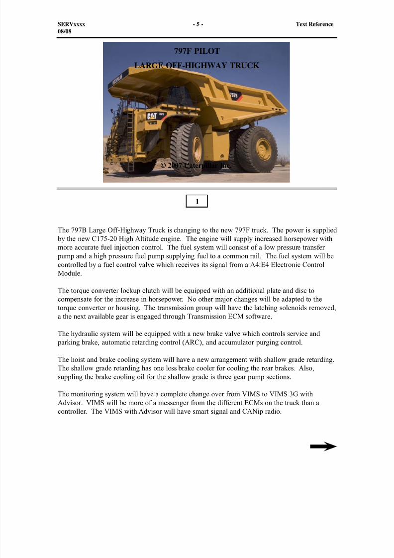
The 797B Large Off-Highway Truck is changing to the new 797F truck. The power is supplied by the new C175-20 High Altitude engine. The engine will supply increased horsepower withmore accurate fuel injection control. The fuel system will consist of a low pressure transfer
pump and a high pressure fuel pump supplying fuel to a common rail. The fuel system will becontrolled by a fuel control valve which receives its signal from a A4:E4 Electronic Control
Module.
The torque converter lockup clutch will be equipped with an additional plate and disc tocompensate for the increase in horsepower. No other major changes will be adapted to thetorque converter or housing. The transmission group will have the latching solenoids removed,a the next available gear is engaged through Transmission ECM software.
The hydraulic system will be equipped with a new brake valve which controls service and parking brake, automatic retarding control (ARC), and accumulator purging control.
The hoist and brake cooling system will have a new arrangement with shallow grade retarding.The shallow grade retarding has one less brake cooler for cooling the rear brakes. Also,suppling the brake cooling oil for the shallow grade is three gear pump sections.
The monitoring system will have a complete change over from VIMS to VIMS 3G withAdvisor. VIMS will be more of a messenger from the different ECMs on the truck than acontroller. The VIMS with Advisor will have smart signal and CANip radio.
1
SERVxxxx - 5 - Text Reference08/08
797F PILOT
LARGE OFF-HIGHWAY TRUCK
© 2007 Caterpillar Inc.
8/9/2019 797F HAA - Meeting Guide.pdf
http://slidepdf.com/reader/full/797f-haa-meeting-guidepdf 6/367
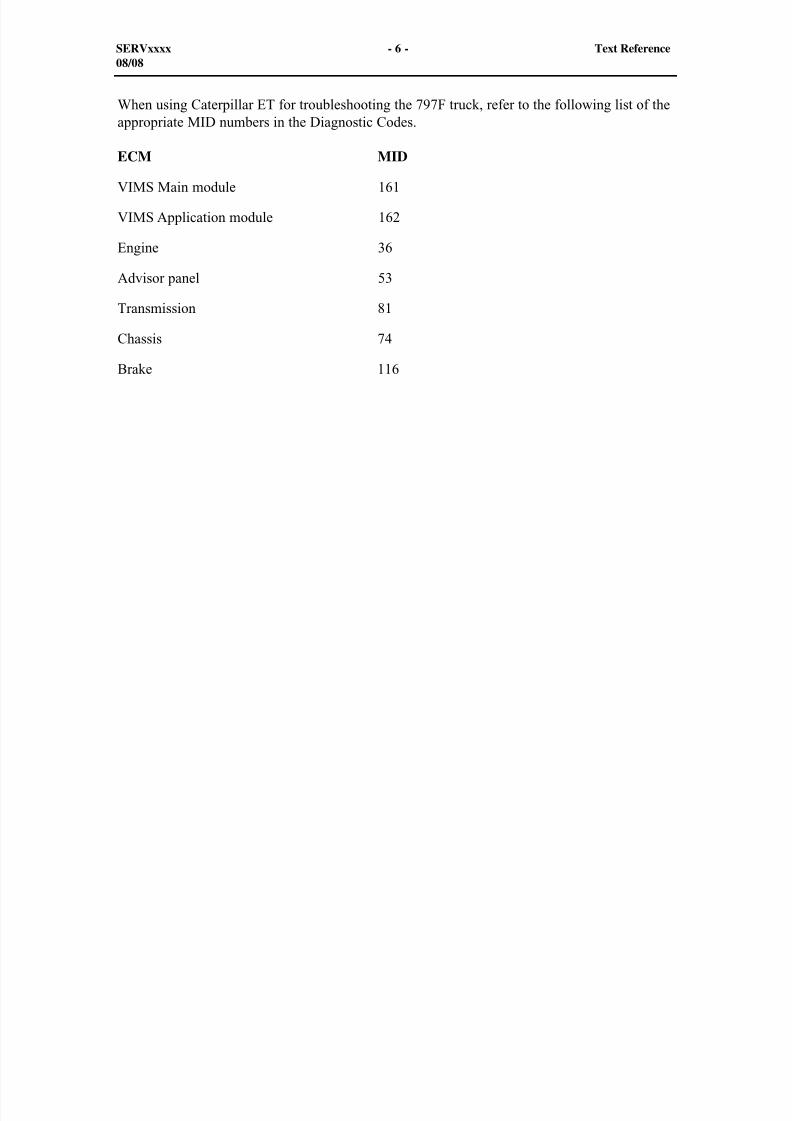
When using Caterpillar ET for troubleshooting the 797F truck, refer to the following list of theappropriate MID numbers in the Diagnostic Codes.
ECM MID
VIMS Main module 161
VIMS Application module 162
Engine 36
Advisor panel 53
Transmission 81
Chassis 74
Brake 116
SERVxxxx - 6 - Text Reference08/08
8/9/2019 797F HAA - Meeting Guide.pdf
http://slidepdf.com/reader/full/797f-haa-meeting-guidepdf 7/367
2
MAINTENANCEBefore maintaining or operating this truck, read the Operation and Maintenance Manualthoroughly for information on safety, maintenance, and operating techniques.
Safety Precautions and Warnings are provided in the manual and on the truck. Be sure toidentify and understand all symbols before starting the truck.
The first step to perform when approaching the truck is to make a thorough walk aroundinspection. Look around and under the truck for loose or missing bolts, trash build-up, and forcoolant, fuel, or oil leaks. Look for indications of cracks. Pay close attention to high stressareas.
SERVxxxx - 7 - Text Reference08/08
8/9/2019 797F HAA - Meeting Guide.pdf
http://slidepdf.com/reader/full/797f-haa-meeting-guidepdf 8/367
The 797F truck is equipped with various maintenance points that should be addressed. Someof the items shown, such as all fluid levels, should be checked daily (see next visual). Someof the items shown, such as engine air filters, should be checked when required. Maintenanceintervals for these items depend mostly on the local conditions. Some locations have moredust, and some locations have loaded uphill hauls, while others have loaded downhill hauls.All of these factors must be considered for some of the maintenance operations.
Most of the maintenance operations are performed at a specific time, or engine hourinterval. The maintenance interval for each operation is normally found in the Operation andMaintenance Manual.
Fuel consumption is the most accurate method for determining maintenance and overhaulintervals. When a machine is sitting stationary with the engine running, the hour meter isalso running, but there is little wear and tear on the machine unless there is over cooling oroverheating of the engine. Fuel consumption is almost zero during idling conditions. Fuel
consumption increases significantly during load conditions and therefore is a good indication ofactual machine usage.
SERVxxxx - 8 - Text Reference08/08
8/9/2019 797F HAA - Meeting Guide.pdf
http://slidepdf.com/reader/full/797f-haa-meeting-guidepdf 9/367
3
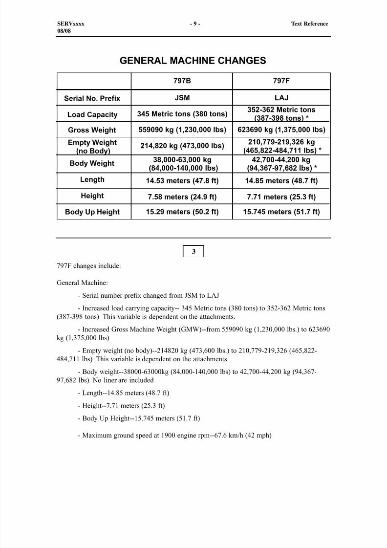
797F changes include:
General Machine:
- Serial number prefix changed from JSM to LAJ
- Increased load carrying capacity-- 345 Metric tons (380 tons) to 352-362 Metric tons(387-398 tons) This variable is dependent on the attachments.
- Increased Gross Machine Weight (GMW)--from 559090 kg (1,230,000 lbs.) to 623690kg (1,375,000 lbs)
- Empty weight (no body)--214820 kg (473,600 lbs.) to 210,779-219,326 (465,822-
484,711 lbs) This variable is dependent on the attachments. - Body weight--38000-63000kg (84,000-140,000 lbs) to 42,700-44,200 kg (94,367-97,682 lbs) No liner are included
- Length--14.85 meters (48.7 ft)
- Height--7.71 meters (25.3 ft)
- Body Up Height--15.745 meters (51.7 ft)
- Maximum ground speed at 1900 engine rpm--67.6 km/h (42 mph)
SERVxxxx - 9 - Text Reference08/08
8/9/2019 797F HAA - Meeting Guide.pdf
http://slidepdf.com/reader/full/797f-haa-meeting-guidepdf 10/367
4
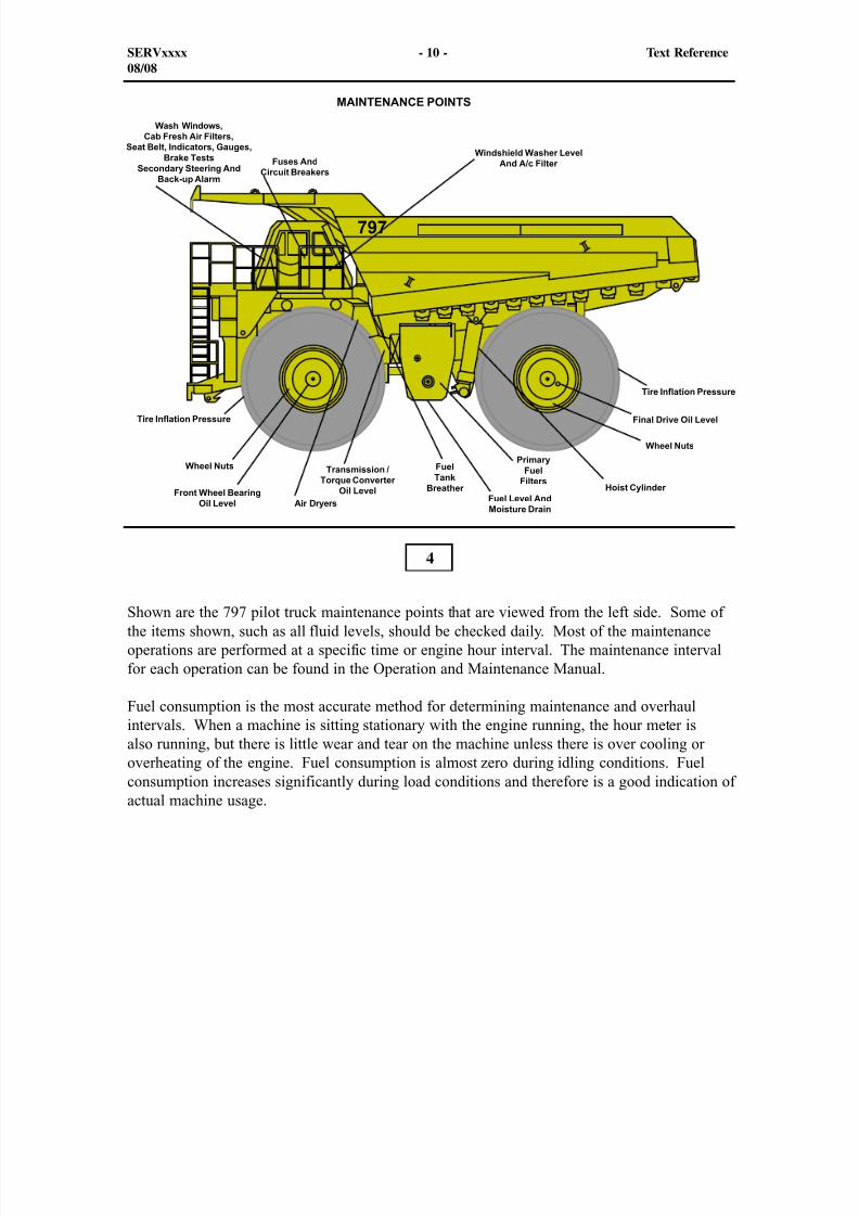
Shown are the 797 pilot truck maintenance points that are viewed from the left side. Some ofthe items shown, such as all fluid levels, should be checked daily. Most of the maintenanceoperations are performed at a specific time or engine hour interval. The maintenance intervalfor each operation can be found in the Operation and Maintenance Manual.
Fuel consumption is the most accurate method for determining maintenance and overhaulintervals. When a machine is sitting stationary with the engine running, the hour meter isalso running, but there is little wear and tear on the machine unless there is over cooling oroverheating of the engine. Fuel consumption is almost zero during idling conditions. Fuelconsumption increases significantly during load conditions and therefore is a good indication ofactual machine usage.
SERVxxxx - 10 - Text Reference08/08
8/9/2019 797F HAA - Meeting Guide.pdf
http://slidepdf.com/reader/full/797f-haa-meeting-guidepdf 11/367
5
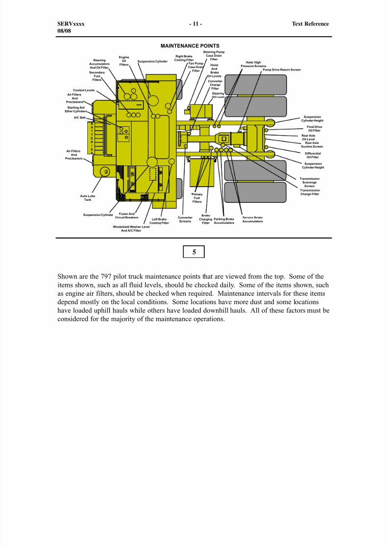
Shown are the 797 pilot truck maintenance points that are viewed from the top. Some of theitems shown, such as all fluid levels, should be checked daily. Some of the items shown, suchas engine air filters, should be checked when required. Maintenance intervals for these itemsdepend mostly on the local conditions. Some locations have more dust and some locationshave loaded uphill hauls while others have loaded downhill hauls. All of these factors must beconsidered for the majority of the maintenance operations.
SERVxxxx - 11 - Text Reference08/08
8/9/2019 797F HAA - Meeting Guide.pdf
http://slidepdf.com/reader/full/797f-haa-meeting-guidepdf 12/367
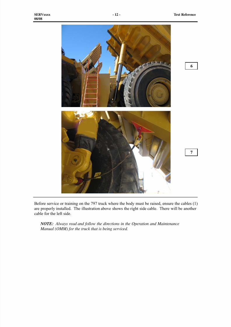
Before service or training on the 797 truck where the body must be raised, ensure the cables (1)are properly installed. The illustration above shows the right side cable. There will be another
cable for the left side.
NOTE: Always read and follow the directions in the Operation and Maintenance Manual (OMM) for the truck that is being serviced.
6
7
SERVxxxx - 12 - Text Reference08/08
8/9/2019 797F HAA - Meeting Guide.pdf
http://slidepdf.com/reader/full/797f-haa-meeting-guidepdf 13/367
1 1 1
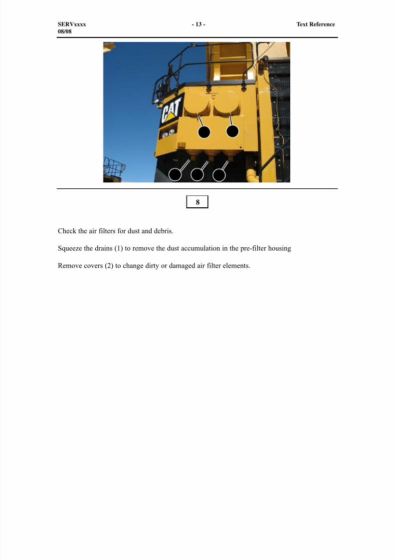
Check the air filters for dust and debris.
Squeeze the drains (1) to remove the dust accumulation in the pre-filter housing
Remove covers (2) to change dirty or damaged air filter elements.
8
SERVxxxx - 13 - Text Reference08/08
2 2

8/9/2019 797F HAA - Meeting Guide.pdf
http://slidepdf.com/reader/full/797f-haa-meeting-guidepdf 14/367
The front wheel bearing oil level is checked through a sight glass (1) that is located in thecenter of the wheel housing. The oil should be level with the bottom of the plug hole. Ifnecessary, remove the plug (2) in the center of the front wheel bearing housing to check thefluid level. Also, this plug is used to fill the front wheel bearing housing.
The oil is drained by removing the magnetic drain plug (3). When draining the oil from thefront wheel bearing housing, rotate the wheel so the drain and fill plug is at the bottom. Inspectthe plug periodically for metal particles. If any metal particles are found, remove the wheelcover and inspect the bearings for wear.
Use only Final Drive and Axle Oil (FDAO) with a specification of (FD-1) or TransmissionDrive Train Oil (TDTO) with a specification of (TO-4) or newer. FDAO and TDTO TO-4
provides increased lubrication capability for bearings.
Check the tire inflation pressure with the valve (4). Operating the truck with the wrong tireinflation pressure can cause heat build-up in the tire and accelerate tire wear.
NOTE: The front wheel oil level on the opposite side will be checked through the sametype of sight glass in the center of the left wheel.
9
SERVxxxx - 14 - Text Reference08/08
1
2
4
3
8/9/2019 797F HAA - Meeting Guide.pdf
http://slidepdf.com/reader/full/797f-haa-meeting-guidepdf 15/367
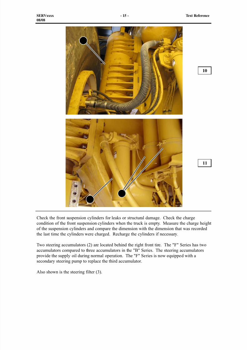
Check the front suspension cylinders for leaks or structural damage. Check the chargecondition of the front suspension cylinders when the truck is empty. Measure the charge height
of the suspension cylinders and compare the dimension with the dimension that was recordedthe last time the cylinders were charged. Recharge the cylinders if necessary.
Two steering accumulators (2) are located behind the right front tire. The "F" Series has twoaccumulators compared to three accumulators in the "B" Series. The steering accumulators
provide the supply oil during normal operation. The "F" Series is now equipped with asecondary steering pump to replace the third accumulator.
Also shown is the steering filter (3).
10
11
SERVxxxx - 15 - Text Reference08/08
2
1
3
8/9/2019 797F HAA - Meeting Guide.pdf
http://slidepdf.com/reader/full/797f-haa-meeting-guidepdf 16/367
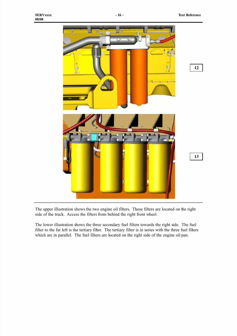
The upper illustration shows the two engine oil filters. These filters are located on the rightside of the truck. Access the filters from behind the right front wheel.
The lower illustration shows the three secondary fuel filters towards the right side. The fuelfilter to the far left is the tertiary filter. The tertiary filter is in series with the three fuel filterswhich are in parallel. The fuel filters are located on the right side of the engine oil pan.
12
13
SERVxxxx - 16 - Text Reference08/08
8/9/2019 797F HAA - Meeting Guide.pdf
http://slidepdf.com/reader/full/797f-haa-meeting-guidepdf 17/367
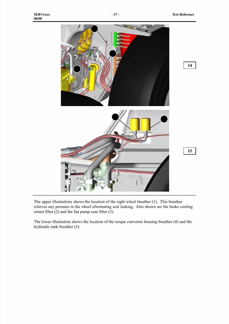
The upper illustrations shows the location of the right wheel breather (1). This breatherrelieves any pressure in the wheel eliminating seal leaking. Also shown are the brake cooling
return filter (2) and the fan pump case filter (3).
The lower illustration shows the location of the torque converter housing breather (4) and thehydraulic tank breather (5).
14
15
SERVxxxx - 17 - Text Reference08/08
1
2
3
45
8/9/2019 797F HAA - Meeting Guide.pdf
http://slidepdf.com/reader/full/797f-haa-meeting-guidepdf 18/367
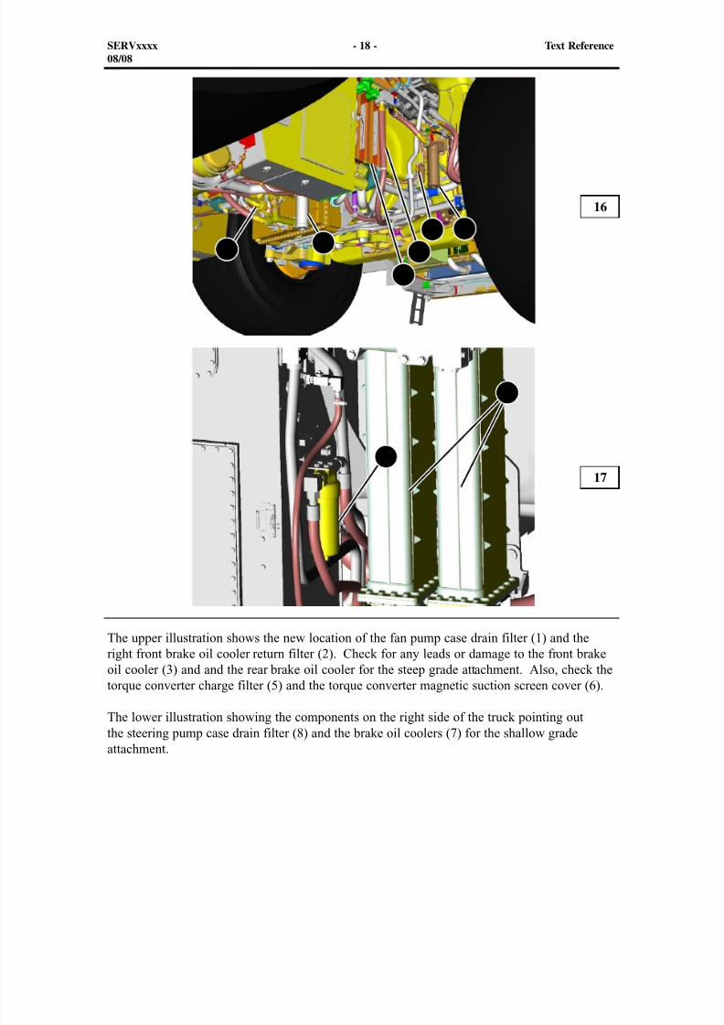
The upper illustration shows the new location of the fan pump case drain filter (1) and theright front brake oil cooler return filter (2). Check for any leads or damage to the front brake
oil cooler (3) and and the rear brake oil cooler for the steep grade attachment. Also, check thetorque converter charge filter (5) and the torque converter magnetic suction screen cover (6).
The lower illustration showing the components on the right side of the truck pointing outthe steering pump case drain filter (8) and the brake oil coolers (7) for the shallow gradeattachment.
16
17
SERVxxxx - 18 - Text Reference08/08
1 2
4
56 3
8
7
8/9/2019 797F HAA - Meeting Guide.pdf
http://slidepdf.com/reader/full/797f-haa-meeting-guidepdf 19/367
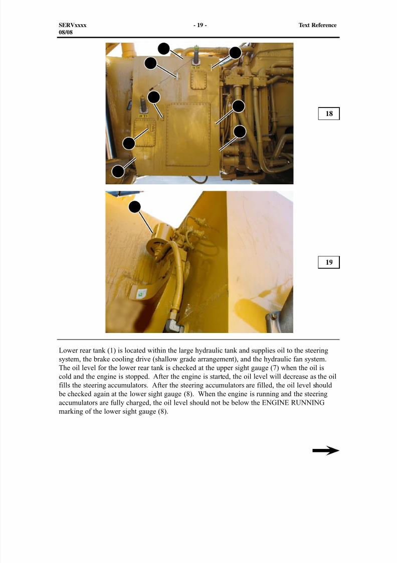
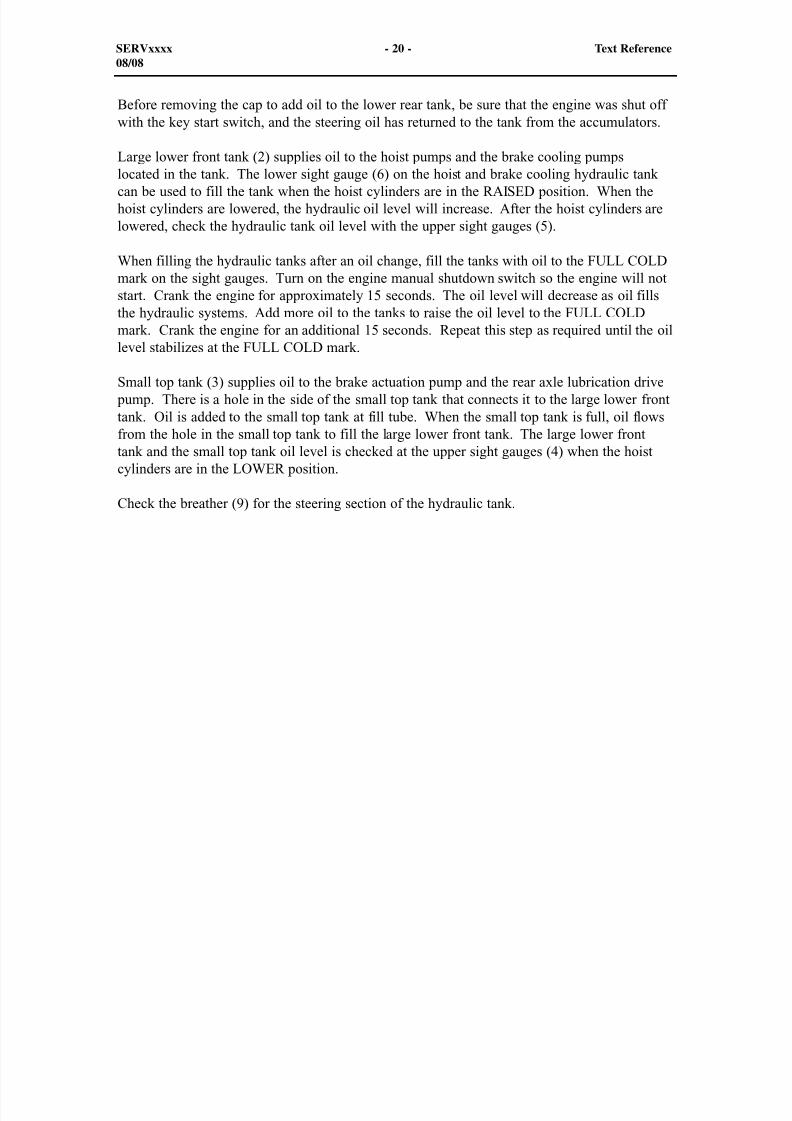
Lower rear tank (1) is located within the large hydraulic tank and supplies oil to the steeringsystem, the brake cooling drive (shallow grade arrangement), and the hydraulic fan system.
The oil level for the lower rear tank is checked at the upper sight gauge (7) when the oil iscold and the engine is stopped. After the engine is started, the oil level will decrease as the oilfills the steering accumulators. After the steering accumulators are filled, the oil level should
be checked again at the lower sight gauge (8). When the engine is running and the steeringaccumulators are fully charged, the oil level should not be below the ENGINE RUNNINGmarking of the lower sight gauge (8).
18
19
SERVxxxx - 19 - Text Reference08/08
1
2
34
5
6
7
8
9
8/9/2019 797F HAA - Meeting Guide.pdf
http://slidepdf.com/reader/full/797f-haa-meeting-guidepdf 20/367
Before removing the cap to add oil to the lower rear tank, be sure that the engine was shut offwith the key start switch, and the steering oil has returned to the tank from the accumulators.
Large lower front tank (2) supplies oil to the hoist pumps and the brake cooling pumpslocated in the tank. The lower sight gauge (6) on the hoist and brake cooling hydraulic tankcan be used to fill the tank when the hoist cylinders are in the RAISED position. When thehoist cylinders are lowered, the hydraulic oil level will increase. After the hoist cylinders arelowered, check the hydraulic tank oil level with the upper sight gauges (5).
When filling the hydraulic tanks after an oil change, fill the tanks with oil to the FULL COLDmark on the sight gauges. Turn on the engine manual shutdown switch so the engine will notstart. Crank the engine for approximately 15 seconds. The oil level will decrease as oil fillsthe hydraulic systems. Add more oil to the tanks to raise the oil level to the FULL COLDmark. Crank the engine for an additional 15 seconds. Repeat this step as required until the oillevel stabilizes at the FULL COLD mark.
Small top tank (3) supplies oil to the brake actuation pump and the rear axle lubrication drive pump. There is a hole in the side of the small top tank that connects it to the large lower fronttank. Oil is added to the small top tank at fill tube. When the small top tank is full, oil flowsfrom the hole in the small top tank to fill the large lower front tank. The large lower fronttank and the small top tank oil level is checked at the upper sight gauges (4) when the hoistcylinders are in the LOWER position.
Check the breather (9) for the steering section of the hydraulic tank.
SERVxxxx - 20 - Text Reference08/08
8/9/2019 797F HAA - Meeting Guide.pdf
http://slidepdf.com/reader/full/797f-haa-meeting-guidepdf 21/367
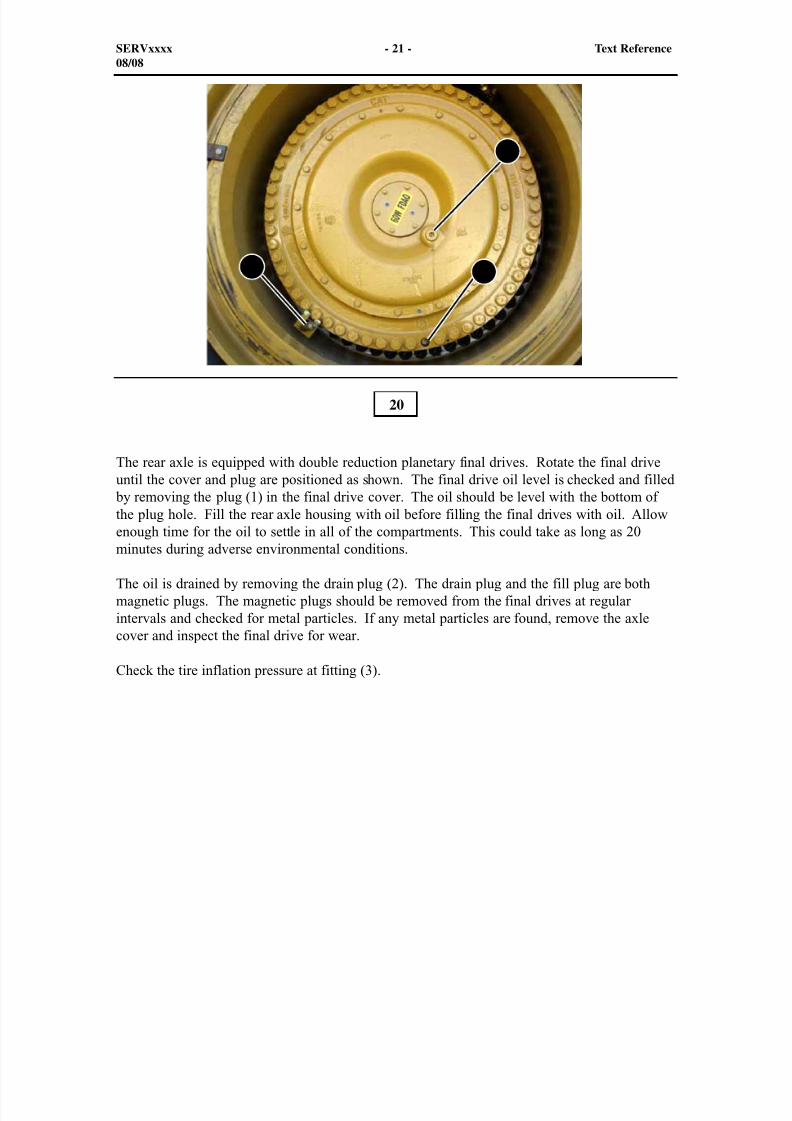
The rear axle is equipped with double reduction planetary final drives. Rotate the final driveuntil the cover and plug are positioned as shown. The final drive oil level is checked and filled
by removing the plug (1) in the final drive cover. The oil should be level with the bottom ofthe plug hole. Fill the rear axle housing with oil before filling the final drives with oil. Allowenough time for the oil to settle in all of the compartments. This could take as long as 20
minutes during adverse environmental conditions.
The oil is drained by removing the drain plug (2). The drain plug and the fill plug are bothmagnetic plugs. The magnetic plugs should be removed from the final drives at regularintervals and checked for metal particles. If any metal particles are found, remove the axlecover and inspect the final drive for wear.
Check the tire inflation pressure at fitting (3).
20
SERVxxxx - 21 - Text Reference08/08
1
23
8/9/2019 797F HAA - Meeting Guide.pdf
http://slidepdf.com/reader/full/797f-haa-meeting-guidepdf 22/367
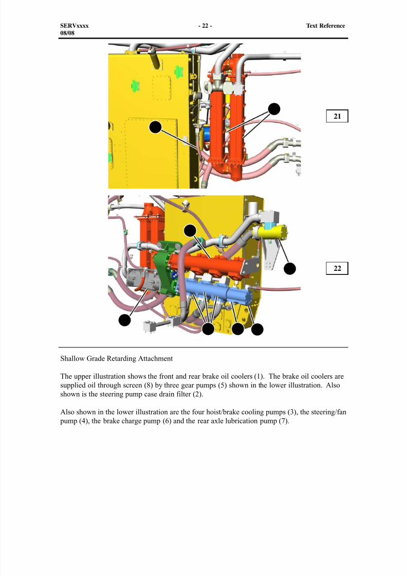
Shallow Grade Retarding Attachment
The upper illustration shows the front and rear brake oil coolers (1). The brake oil coolers aresupplied oil through screen (8) by three gear pumps (5) shown in the lower illustration. Alsoshown is the steering pump case drain filter (2).
Also shown in the lower illustration are the four hoist/brake cooling pumps (3), the steering/fan pump (4), the brake charge pump (6) and the rear axle lubrication pump (7).
21
22
SERVxxxx - 22 - Text Reference08/08
1
2
5 6 7
4
3
8
8/9/2019 797F HAA - Meeting Guide.pdf
http://slidepdf.com/reader/full/797f-haa-meeting-guidepdf 23/367
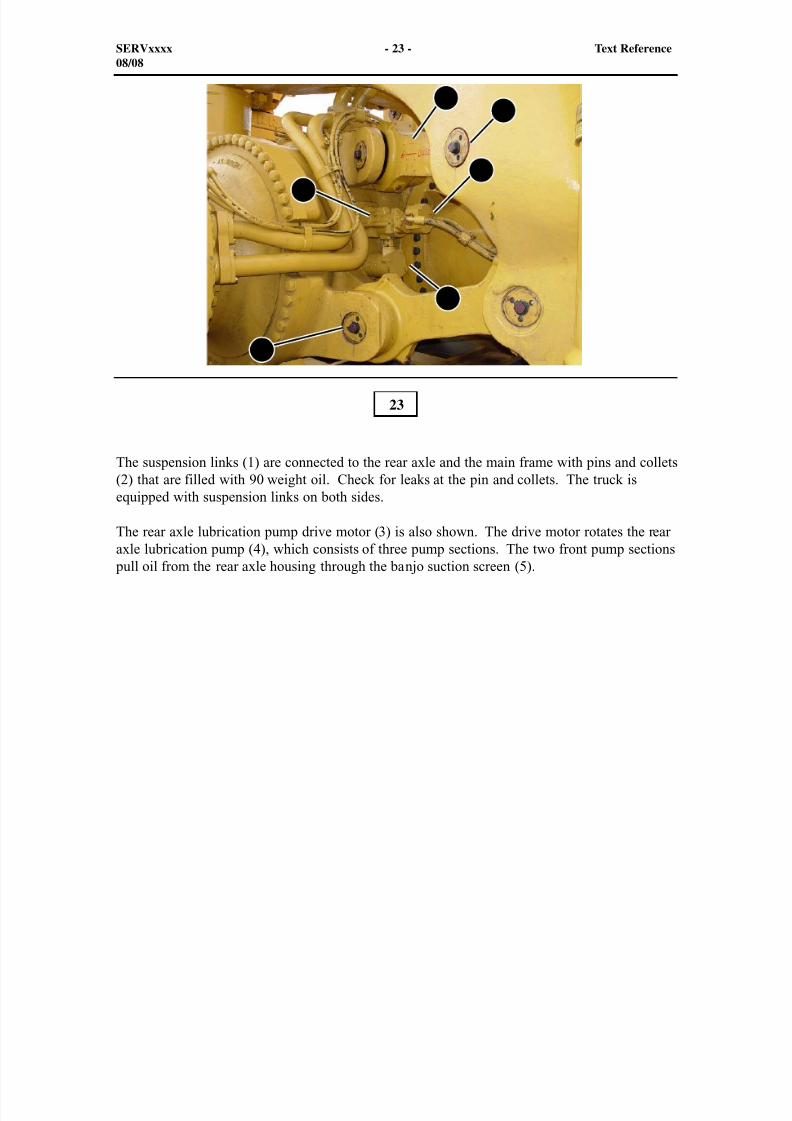
The suspension links (1) are connected to the rear axle and the main frame with pins and collets(2) that are filled with 90 weight oil. Check for leaks at the pin and collets. The truck isequipped with suspension links on both sides.
The rear axle lubrication pump drive motor (3) is also shown. The drive motor rotates the rear
axle lubrication pump (4), which consists of three pump sections. The two front pump sections pull oil from the rear axle housing through the banjo suction screen (5).
23
SERVxxxx - 23 - Text Reference08/08
4
12
2
3
5
8/9/2019 797F HAA - Meeting Guide.pdf
http://slidepdf.com/reader/full/797f-haa-meeting-guidepdf 24/367
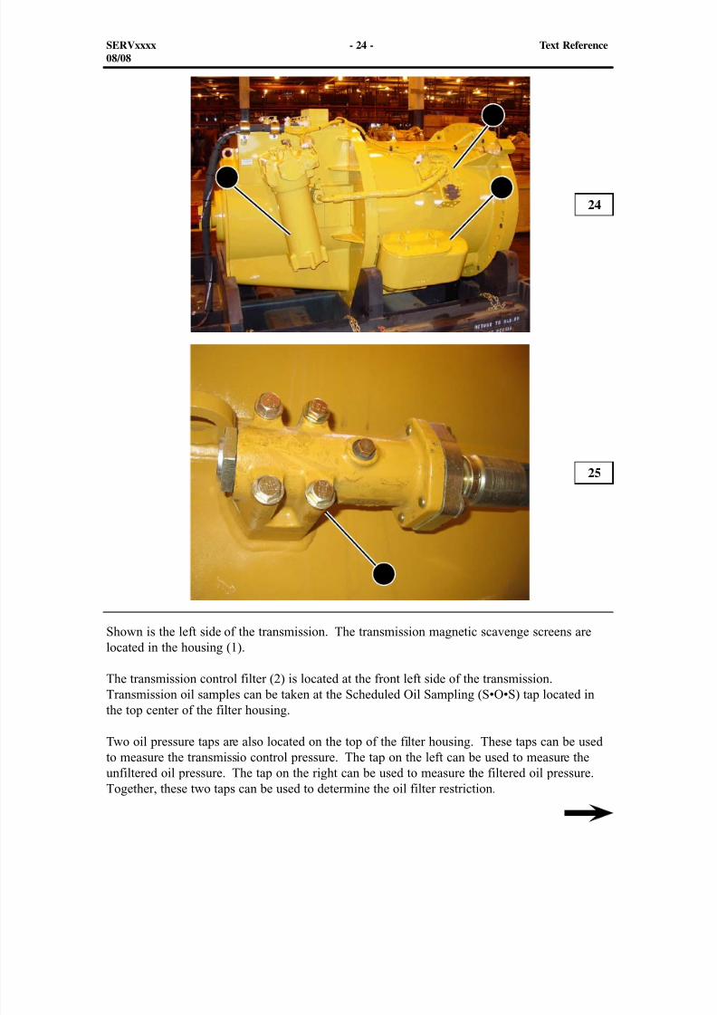
Shown is the left side of the transmission. The transmission magnetic scavenge screens arelocated in the housing (1).
The transmission control filter (2) is located at the front left side of the transmission.Transmission oil samples can be taken at the Scheduled Oil Sampling (S•O•S) tap located inthe top center of the filter housing.
Two oil pressure taps are also located on the top of the filter housing. These taps can be usedto measure the transmissio control pressure. The tap on the left can be used to measure theunfiltered oil pressure. The tap on the right can be used to measure the filtered oil pressure.Together, these two taps can be used to determine the oil filter restriction.
24
25
SERVxxxx - 24 - Text Reference08/08
12
3
4

8/9/2019 797F HAA - Meeting Guide.pdf
http://slidepdf.com/reader/full/797f-haa-meeting-guidepdf 25/367
An oil filter bypass switch is also located on the filter housing. The bypass switch provides aninput signal to the Transmission Electronic Control Module (ECM). The Transmission ECMrelays the signal to the Advisor Panel, which informs the operator if the filter is restricted.
The transmission lube relief valve (3) is also located on the left side of the transmission case.The transmission temperature sensor and the transmission lube pressure sensor are located onthis valve. The two sensors provide input signals to the Transmission ECM. The TransmissionECM relays the signal to the Advisor Panel, which informs the operator of the transmissiontemperature and lube pressure.
The pump drive is lubricated by transmission and torque converter oil. The pump drivelubrication oil returns to the transmission sump through the screen housing (4). Check thescreen for plugging when required.
SERVxxxx - 25 - Text Reference08/08
8/9/2019 797F HAA - Meeting Guide.pdf
http://slidepdf.com/reader/full/797f-haa-meeting-guidepdf 26/367
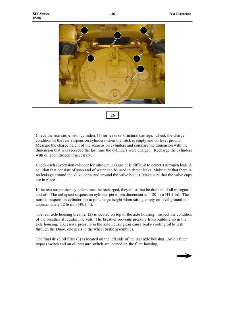
Check the rear suspension cylinders (1) for leaks or structural damage. Check the chargecondition of the rear suspension cylinders when the truck is empty and on level ground.Measure the charge height of the suspension cylinders and compare the dimension with thedimension that was recorded the last time the cylinders were charged. Recharge the cylinders
with oil and nitrogen if necessary.
Check each suspension cylinder for nitrogen leakage. It is difficult to detect a nitrogen leak. Asolution that consists of soap and of water can be used to detect leaks. Make sure that there isno leakage around the valve cores and around the valve bodies. Make sure that the valve capsare in place.
If the rear suspension cylinders must be recharged, they must first be drained of all nitrogenand oil. The collapsed suspension cylinder pin to pin dimension is 1120 mm (44.1 in). Thenormal suspension cylinder pin to pin charge height when sitting empty on level ground isapproximately 1246 mm (49.1 in).
The rear axle housing breather (2) is located on top of the axle housing. Inspect the conditionof the breather at regular intervals. The breather prevents pressure from building up in theaxle housing. Excessive pressure in the axle housing can cause brake cooling oil to leakthrough the Duo-Cone seals in the wheel brake assemblies.
The final drive oil filter (3) is located on the left side of the rear axle housing. An oil filter bypass switch and an oil pressure switch are located on the filter housing.
26
SERVxxxx - 26 - Text Reference08/08
11
2
3 4
5

8/9/2019 797F HAA - Meeting Guide.pdf
http://slidepdf.com/reader/full/797f-haa-meeting-guidepdf 27/367
The differential oil filter (4) is located on the right side of the rear axle housing. An oil filter bypass switch and an oil pressure sensor are located on the filter housing.
Located on the right side of the rear cover for the banjo housing is the oil level sight glass (5).The glass gives the technician access to the level of oil in the differential.
SERVxxxx - 27 - Text Reference08/08
8/9/2019 797F HAA - Meeting Guide.pdf
http://slidepdf.com/reader/full/797f-haa-meeting-guidepdf 28/367
1
2
3
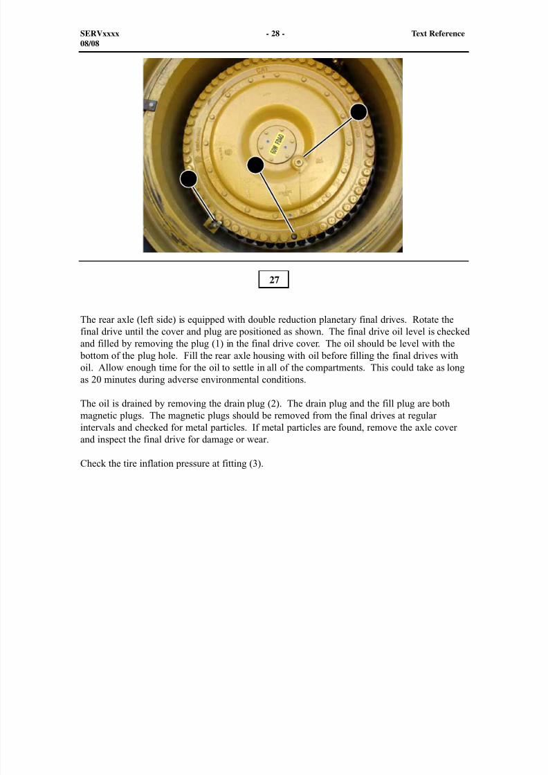
The rear axle (left side) is equipped with double reduction planetary final drives. Rotate thefinal drive until the cover and plug are positioned as shown. The final drive oil level is checkedand filled by removing the plug (1) in the final drive cover. The oil should be level with the
bottom of the plug hole. Fill the rear axle housing with oil before filling the final drives withoil. Allow enough time for the oil to settle in all of the compartments. This could take as long
as 20 minutes during adverse environmental conditions.
The oil is drained by removing the drain plug (2). The drain plug and the fill plug are bothmagnetic plugs. The magnetic plugs should be removed from the final drives at regularintervals and checked for metal particles. If metal particles are found, remove the axle coverand inspect the final drive for damage or wear.
Check the tire inflation pressure at fitting (3).
27
SERVxxxx - 28 - Text Reference08/08
8/9/2019 797F HAA - Meeting Guide.pdf
http://slidepdf.com/reader/full/797f-haa-meeting-guidepdf 29/367
1
2
3
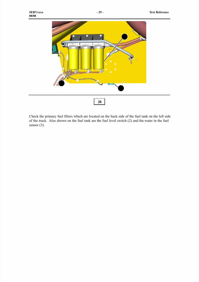
Check the primary fuel filters which are located on the back side of the fuel tank on the left sideof the truck. Also shown on the fuel tank are the fuel level switch (2) and the water in the fuelsensor (3).
28
SERVxxxx - 29 - Text Reference08/08
8/9/2019 797F HAA - Meeting Guide.pdf
http://slidepdf.com/reader/full/797f-haa-meeting-guidepdf 30/367
1
2
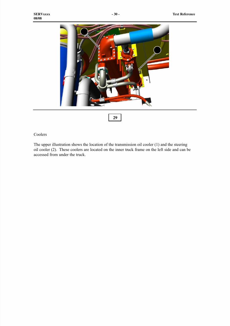
Coolers
The upper illustration shows the location of the transmission oil cooler (1) and the steeringoil cooler (2). These coolers are located on the inner truck frame on the left side and can beaccessed from under the truck.
29
SERVxxxx - 30 - Text Reference08/08
8/9/2019 797F HAA - Meeting Guide.pdf
http://slidepdf.com/reader/full/797f-haa-meeting-guidepdf 31/367
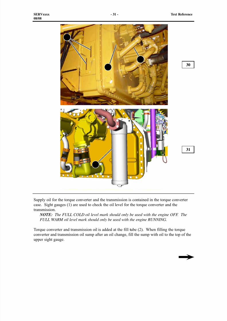
Supply oil for the torque converter and the transmission is contained in the torque convertercase. Sight gauges (1) are used to check the oil level for the torque converter and the
transmission. NOTE: The FULL COLD oil level mark should only be used with the engine OFF. TheFULL WARM oil level mark should only be used with the engine RUNNING.
Torque converter and transmission oil is added at the fill tube (2). When filling the torqueconverter and transmission oil sump after an oil change, fill the sump with oil to the top of theupper sight gauge.
30
31
SERVxxxx - 31 - Text Reference08/08
1
2
3
4

8/9/2019 797F HAA - Meeting Guide.pdf
http://slidepdf.com/reader/full/797f-haa-meeting-guidepdf 32/367
The torque converter outlet screen (top) and the magnetic suction screen (bottom) are located behind the cover (3). Located on the cover is the torque converter oil temperature sensor andthe torque converter outlet screen bypass switch. The temperature sensor and the bypass switch
provide input signals to the Transmission ECM.
Located on the right side of the torque converter housing is thetorque converter charging filter (4). Torque Converter oil samples can be taken at theScheduled Oil Sampling (S•O•S) tap (not shown) located in the top center of the filter housing.
SERVxxxx - 32 - Text Reference08/08
8/9/2019 797F HAA - Meeting Guide.pdf
http://slidepdf.com/reader/full/797f-haa-meeting-guidepdf 33/367
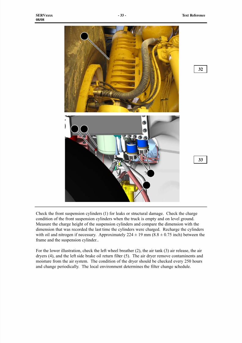
Check the front suspension cylinders (1) for leaks or structural damage. Check the chargecondition of the front suspension cylinders when the truck is empty and on level ground.
Measure the charge height of the suspension cylinders and compare the dimension with thedimension that was recorded the last time the cylinders were charged. Recharge the cylinderswith oil and nitrogen if necessary. Approximately 224 ± 19 mm (8.8 ± 0.75 inch) between theframe and the suspension cylinder..
For the lower illustration, check the left wheel breather (2), the air tank (3) air release, the airdryers (4), and the left side brake oil return filter (5). The air dryer remove contaminents andmoisture from the air system. The condition of the dryer should be checked every 250 hoursand change periodically. The local environment determines the filter change schedule.
32
33
SERVxxxx - 33 - Text Reference08/08
1
2 3
4
5
8/9/2019 797F HAA - Meeting Guide.pdf
http://slidepdf.com/reader/full/797f-haa-meeting-guidepdf 34/367
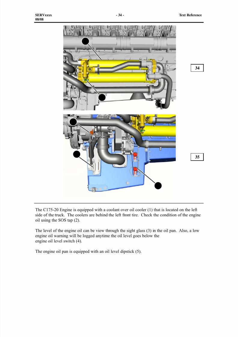
The C175-20 Engine is equipped with a coolant over oil cooler (1) that is located on the leftside of the truck. The coolers are behind the left front tire. Check the condition of the engine
oil using the SOS tap (2).
The level of the engine oil can be view through the sight glass (3) in the oil pan. Also, a lowengine oil warning will be logged anytime the oil level goes below theengine oil level switch (4).
The engine oil pan is equipped with an oil level dipstick (5).
34
35
SERVxxxx - 34 - Text Reference08/08
1
2
3
4
5
8/9/2019 797F HAA - Meeting Guide.pdf
http://slidepdf.com/reader/full/797f-haa-meeting-guidepdf 35/367
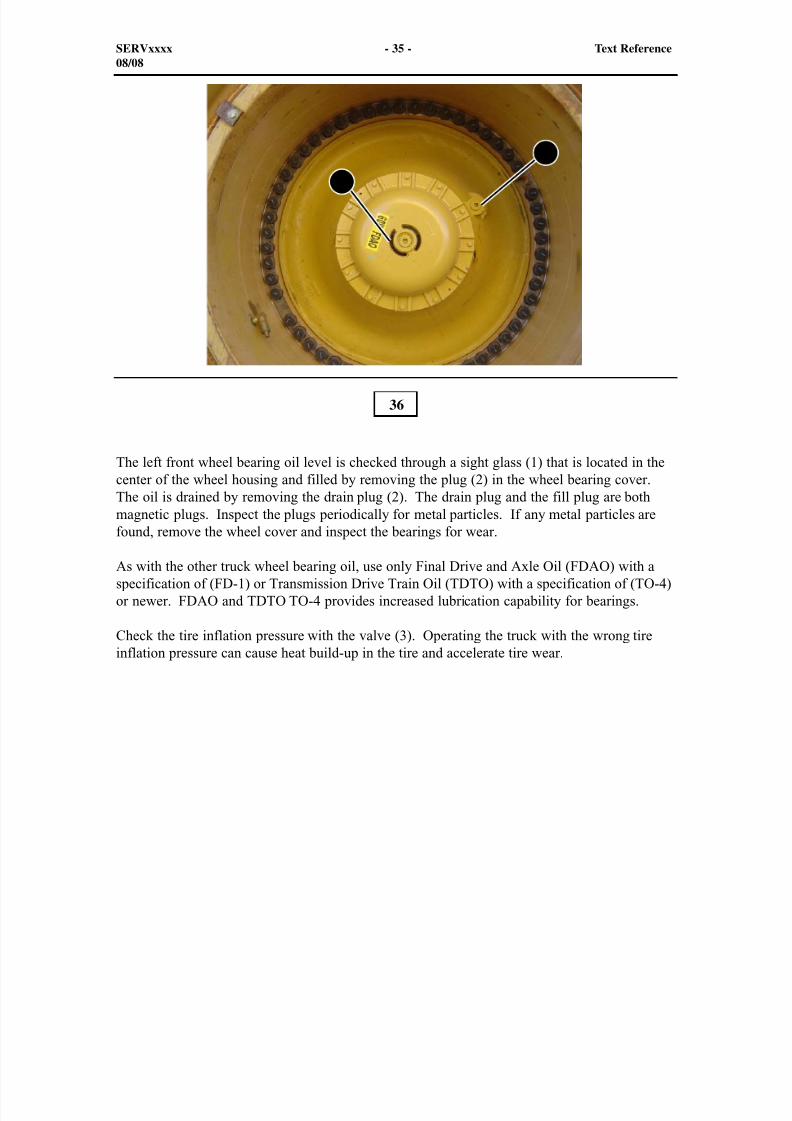
The left front wheel bearing oil level is checked through a sight glass (1) that is located in thecenter of the wheel housing and filled by removing the plug (2) in the wheel bearing cover.The oil is drained by removing the drain plug (2). The drain plug and the fill plug are bothmagnetic plugs. Inspect the plugs periodically for metal particles. If any metal particles arefound, remove the wheel cover and inspect the bearings for wear.
As with the other truck wheel bearing oil, use only Final Drive and Axle Oil (FDAO) with aspecification of (FD-1) or Transmission Drive Train Oil (TDTO) with a specification of (TO-4)or newer. FDAO and TDTO TO-4 provides increased lubrication capability for bearings.
Check the tire inflation pressure with the valve (3). Operating the truck with the wrong tireinflation pressure can cause heat build-up in the tire and accelerate tire wear.
36
SERVxxxx - 35 - Text Reference08/08
1
2

8/9/2019 797F HAA - Meeting Guide.pdf
http://slidepdf.com/reader/full/797f-haa-meeting-guidepdf 36/367
1
23
4
Check the air supply system. There are two relief valves (1), one on each tank at the top. Therelief valves open at approximately 1033 kPa (150 psi). Each valve has a test pin installed.
There is a hose that is common to both tanks (shown). From the larger tank, there is a hosewhich is connected to the frame with a manual drain valve (2). Also shown is the external air
supply (3).
The air start valve (4) is installed on the inside of the frame below the smaller air tank. Thevalve is electronically controlled by the Chassis ECM.
37
SERVxxxx - 36 - Text Reference08/08
8/9/2019 797F HAA - Meeting Guide.pdf
http://slidepdf.com/reader/full/797f-haa-meeting-guidepdf 37/367
11
2 2 2
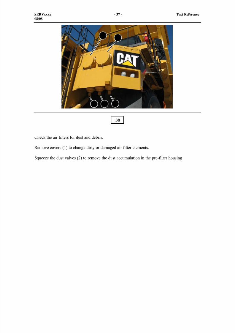
Check the air filters for dust and debris.
Remove covers (1) to change dirty or damaged air filter elements.
Squeeze the dust valves (2) to remove the dust accumulation in the pre-filter housing
38
SERVxxxx - 37 - Text Reference08/08
8/9/2019 797F HAA - Meeting Guide.pdf
http://slidepdf.com/reader/full/797f-haa-meeting-guidepdf 38/367
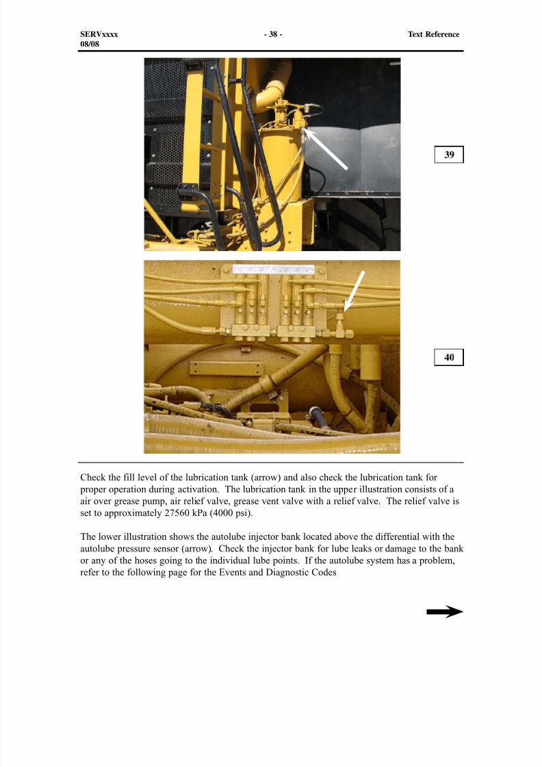
Check the fill level of the lubrication tank (arrow) and also check the lubrication tank for proper operation during activation. The lubrication tank in the upper illustration consists of a
air over grease pump, air relief valve, grease vent valve with a relief valve. The relief valve isset to approximately 27560 kPa (4000 psi).
The lower illustration shows the autolube injector bank located above the differential with theautolube pressure sensor (arrow). Check the injector bank for lube leaks or damage to the bankor any of the hoses going to the individual lube points. If the autolube system has a problem,refer to the following page for the Events and Diagnostic Codes
39
40
SERVxxxx - 38 - Text Reference08/08
8/9/2019 797F HAA - Meeting Guide.pdf
http://slidepdf.com/reader/full/797f-haa-meeting-guidepdf 39/367
The sensor now signals the Chassis ECM when the lube pressure has not reached the cutoff pressure as the autolube timer expires. Event E334 will become active and logged
The autolube pressure does not go below the reset pressure within a set interval after the lubingcycle is complete. Event E521 will become active and logged
NOTE: The Event will be inhibited while there is an active CID 379 Diagnostic Code.
Diagnostic Code for the Autolube pressure sensor is
MID 057 - CID 379 - FMI 03 Autolube pressure sensor - Voltage above normal
MID 057 - CID 379 - FMI 04 Autolube pressure sensor - Voltage below normal
MID 057 - CID 379 - FMI 08 Autolube pressure sensor - Abnormal frequency, pulsewidth, or period
Diagnostic Code for the Autolube relay (located in the cab) is
MID 057 - CID 558 - FMI 03 Autolube relay - Voltage above normal MID 057 - CID 558 - FMI 05 Autolube relay - Current below normal
MID 057 - CID 558 - FMI 06 Autolube relay - Current above normal
SERVxxxx - 39 - Text Reference08/08
8/9/2019 797F HAA - Meeting Guide.pdf
http://slidepdf.com/reader/full/797f-haa-meeting-guidepdf 40/367
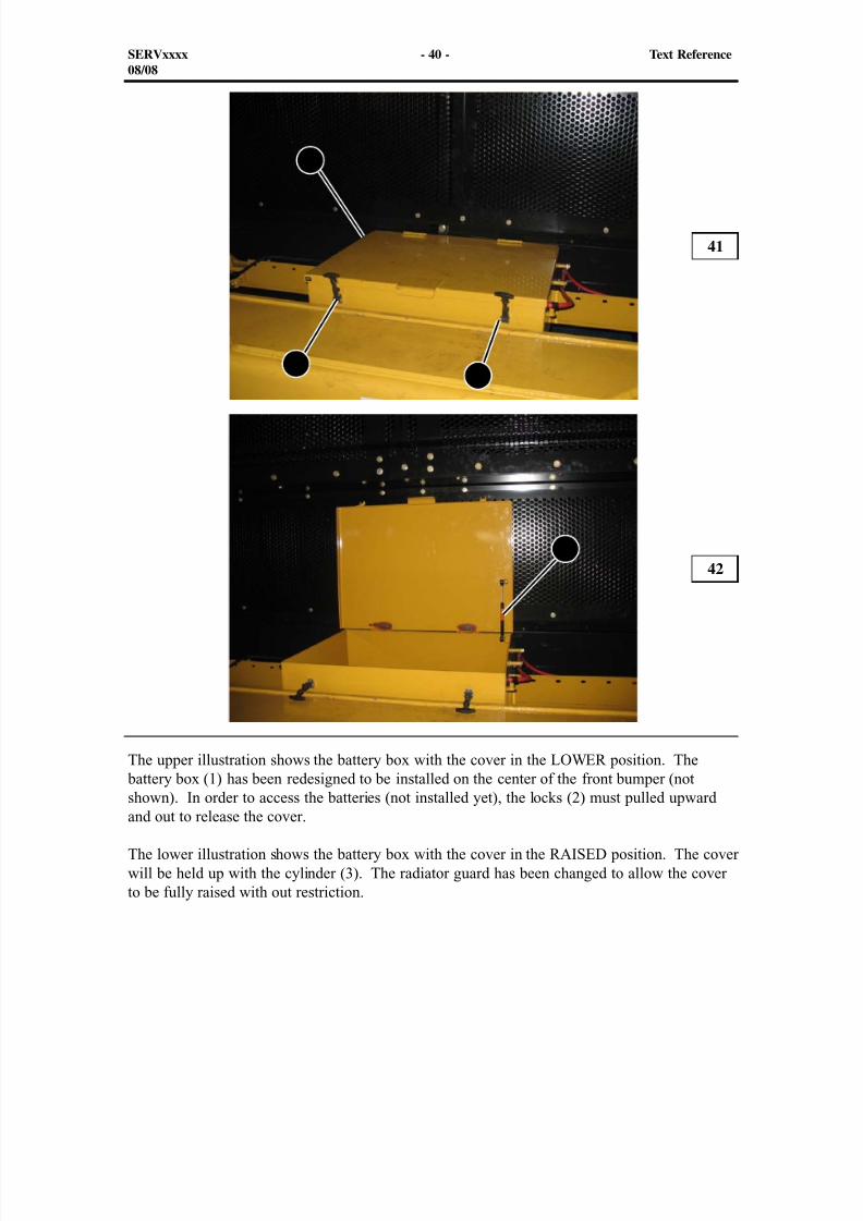
The upper illustration shows the battery box with the cover in the LOWER position. The battery box (1) has been redesigned to be installed on the center of the front bumper (not
shown). In order to access the batteries (not installed yet), the locks (2) must pulled upwardand out to release the cover.
The lower illustration shows the battery box with the cover in the RAISED position. The coverwill be held up with the cylinder (3). The radiator guard has been changed to allow the coverto be fully raised with out restriction.
41
42
SERVxxxx - 40 - Text Reference08/08
1
22
3
8/9/2019 797F HAA - Meeting Guide.pdf
http://slidepdf.com/reader/full/797f-haa-meeting-guidepdf 41/367
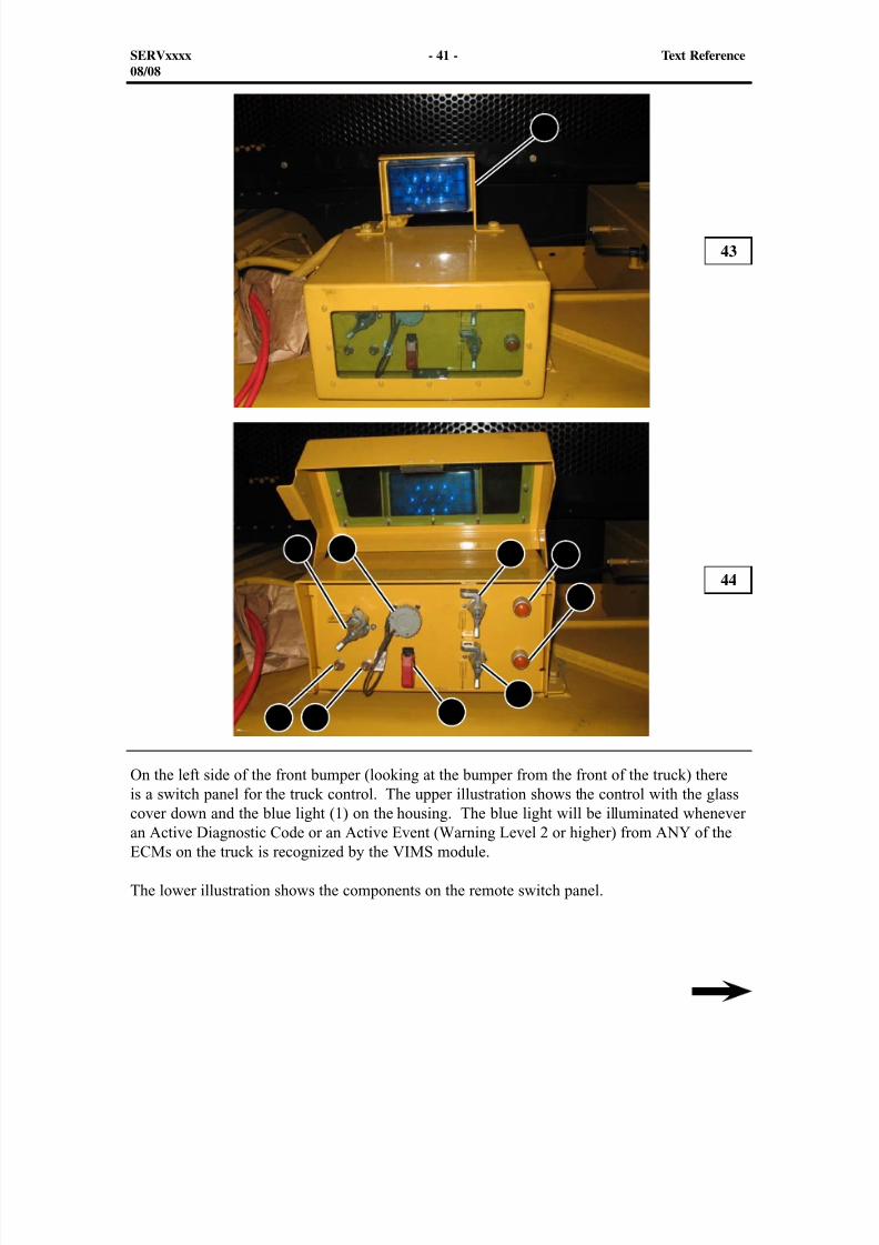
On the left side of the front bumper (looking at the bumper from the front of the truck) thereis a switch panel for the truck control. The upper illustration shows the control with the glass
cover down and the blue light (1) on the housing. The blue light will be illuminated wheneveran Active Diagnostic Code or an Active Event (Warning Level 2 or higher) from ANY of theECMs on the truck is recognized by the VIMS module.
The lower illustration shows the components on the remote switch panel.
43
44
SERVxxxx - 41 - Text Reference08/08
1
2 3 4 5
6
789 10
8/9/2019 797F HAA - Meeting Guide.pdf
http://slidepdf.com/reader/full/797f-haa-meeting-guidepdf 42/367
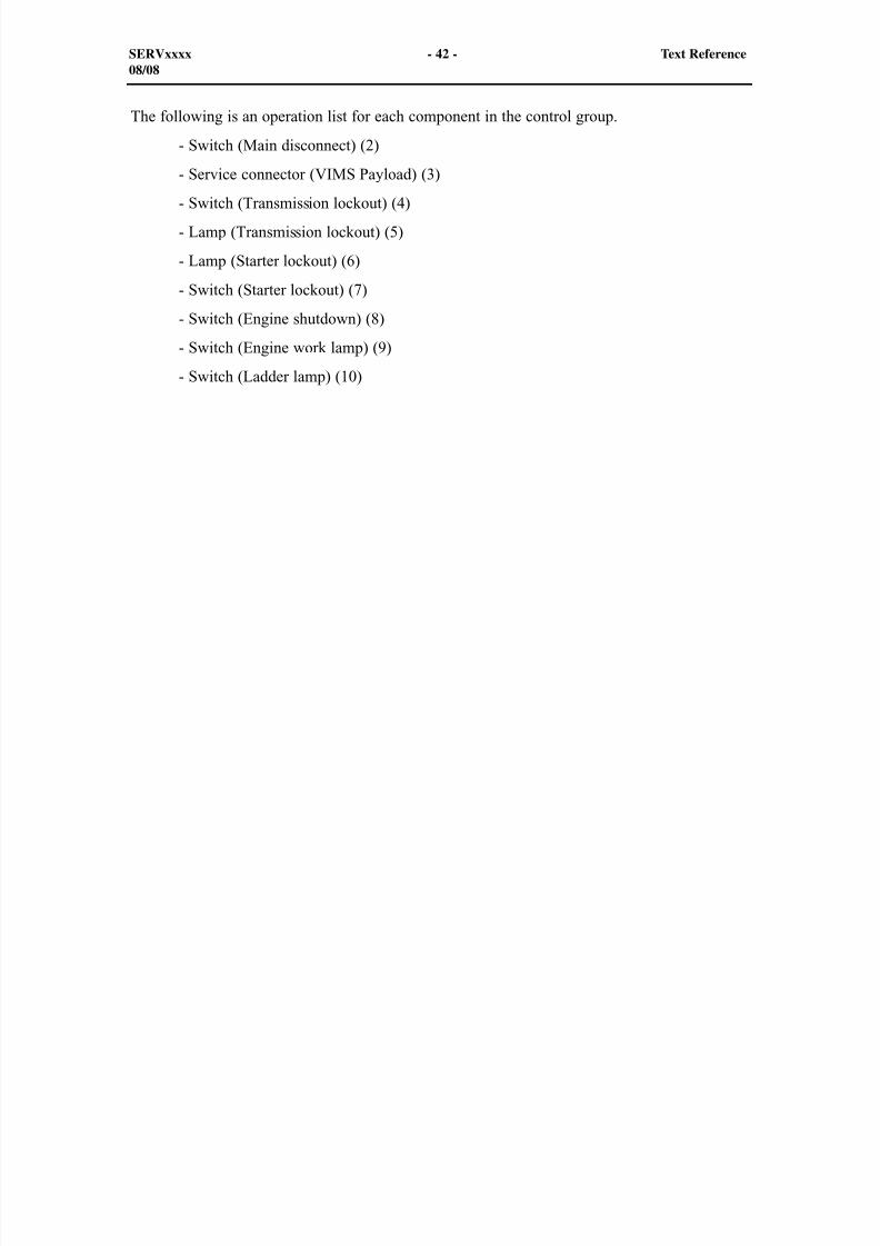
The following is an operation list for each component in the control group.
- Switch (Main disconnect) (2)
- Service connector (VIMS Payload) (3)
- Switch (Transmission lockout) (4) - Lamp (Transmission lockout) (5)
- Lamp (Starter lockout) (6)
- Switch (Starter lockout) (7)
- Switch (Engine shutdown) (8)
- Switch (Engine work lamp) (9)
- Switch (Ladder lamp) (10)
SERVxxxx - 42 - Text Reference08/08
8/9/2019 797F HAA - Meeting Guide.pdf
http://slidepdf.com/reader/full/797f-haa-meeting-guidepdf 43/367
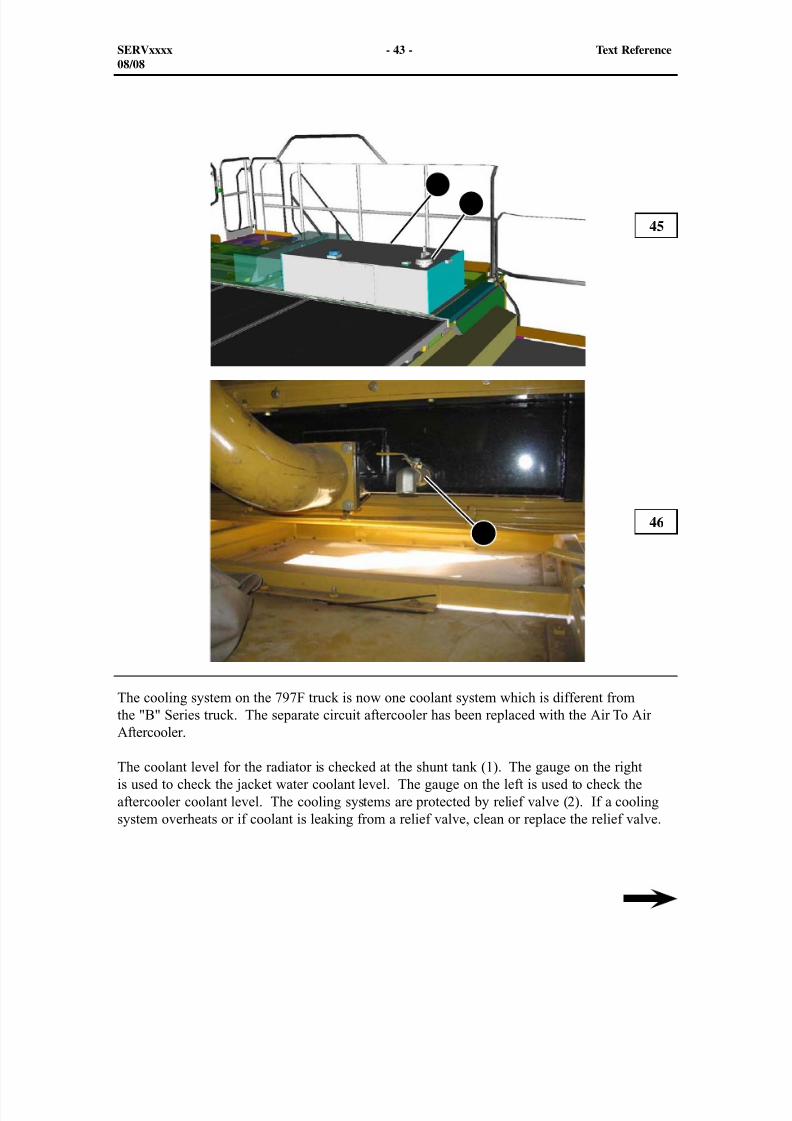
The cooling system on the 797F truck is now one coolant system which is different fromthe "B" Series truck. The separate circuit aftercooler has been replaced with the Air To Air
Aftercooler.
The coolant level for the radiator is checked at the shunt tank (1). The gauge on the rightis used to check the jacket water coolant level. The gauge on the left is used to check theaftercooler coolant level. The cooling systems are protected by relief valve (2). If a coolingsystem overheats or if coolant is leaking from a relief valve, clean or replace the relief valve.
45
46
SERVxxxx - 43 - Text Reference08/08
12
3

8/9/2019 797F HAA - Meeting Guide.pdf
http://slidepdf.com/reader/full/797f-haa-meeting-guidepdf 44/367
The "F" Series truck will be filled with Extended Life Coolant (ELC) at the factory. If ELC ismaintained in the radiator, it is not necessary to use a supplemental coolant additive. If morethan 10% of conventional coolant is mixed with the ELC, a supplemental coolant additive isrequired.
NOTE: Never use water alone. All water is corrosive at engine operating temperatureswithout coolant additives. Also, water alone has none of the lubrication propertieswhich are required for water pump seals.
Engine coolant change valve (3) is located in the bottom tank assembly. Follow all rules in thedisassembly and assembly when draining the coolant.
SERVxxxx - 44 - Text Reference08/08
8/9/2019 797F HAA - Meeting Guide.pdf
http://slidepdf.com/reader/full/797f-haa-meeting-guidepdf 45/367
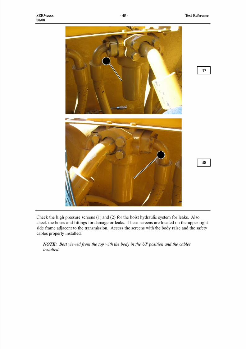
Check the high pressure screens (1) and (2) for the hoist hydraulic system for leaks. Also,check the hoses and fittings for damage or leaks. These screens are located on the upper right
side frame adjacent to the transmission. Access the screens with the body raise and the safetycables properly installed.
NOTE: Best viewed from the top with the body in the UP position and the cablesinstalled.
47
48
SERVxxxx - 45 - Text Reference08/08
1
2
8/9/2019 797F HAA - Meeting Guide.pdf
http://slidepdf.com/reader/full/797f-haa-meeting-guidepdf 46/367
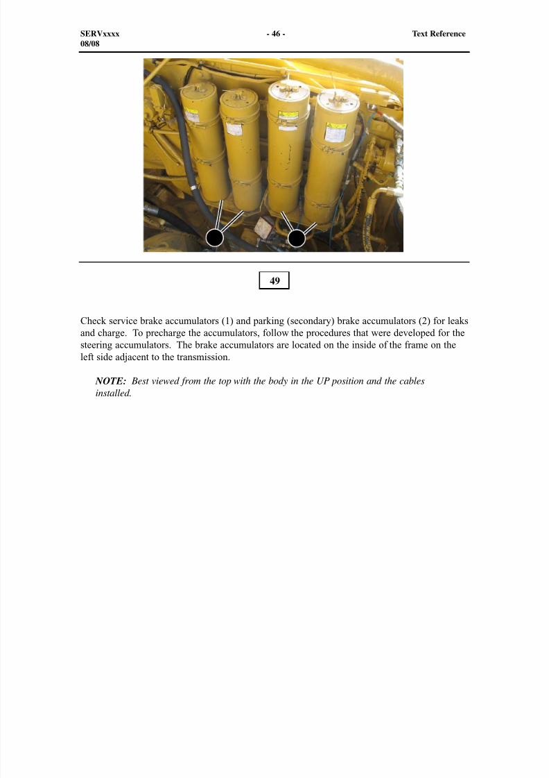
Check service brake accumulators (1) and parking (secondary) brake accumulators (2) for leaksand charge. To precharge the accumulators, follow the procedures that were developed for thesteering accumulators. The brake accumulators are located on the inside of the frame on theleft side adjacent to the transmission.
NOTE: Best viewed from the top with the body in the UP position and the cablesinstalled.
49
SERVxxxx - 46 - Text Reference08/08
1 2
8/9/2019 797F HAA - Meeting Guide.pdf
http://slidepdf.com/reader/full/797f-haa-meeting-guidepdf 47/367
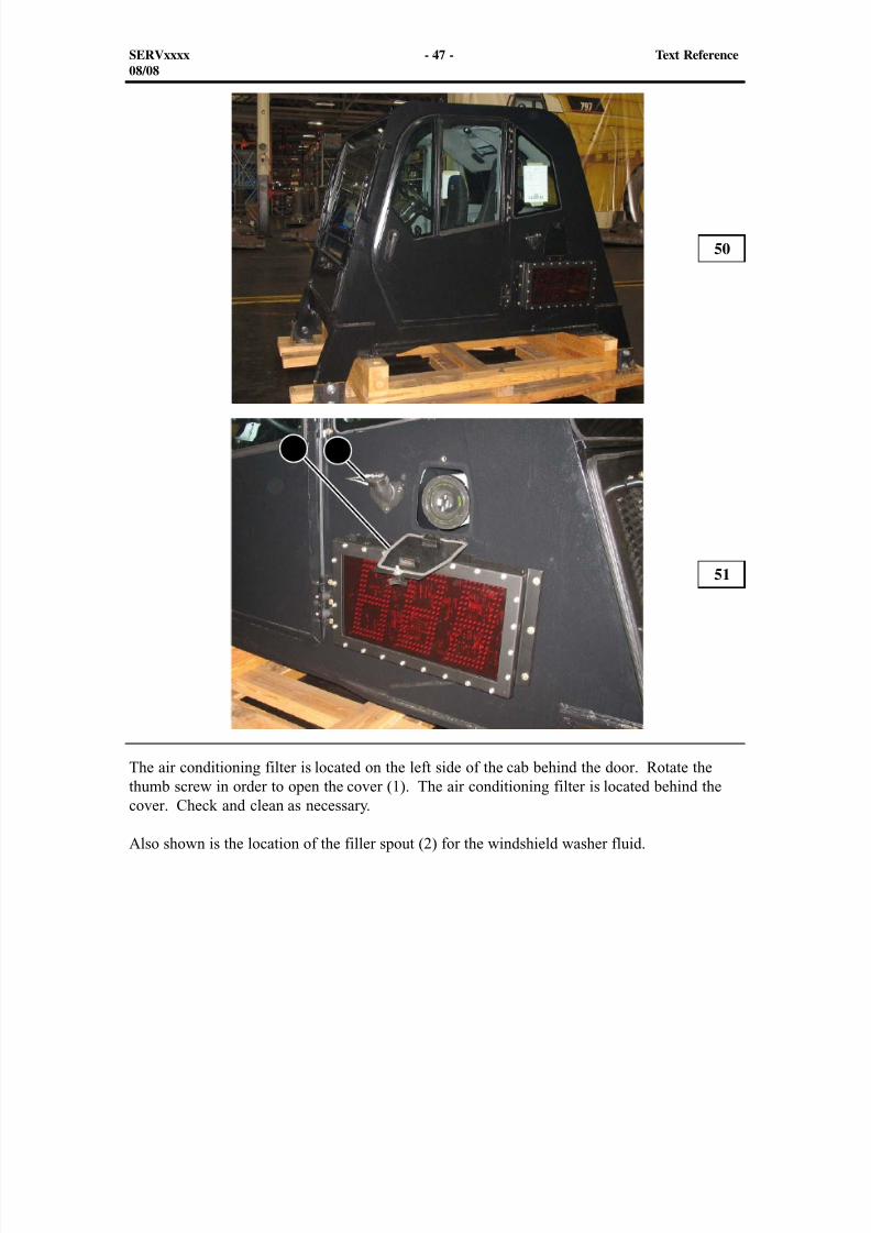
The air conditioning filter is located on the left side of the cab behind the door. Rotate thethumb screw in order to open the cover (1). The air conditioning filter is located behind the
cover. Check and clean as necessary.
Also shown is the location of the filler spout (2) for the windshield washer fluid.
50
51
SERVxxxx - 47 - Text Reference08/08
1 2
8/9/2019 797F HAA - Meeting Guide.pdf
http://slidepdf.com/reader/full/797f-haa-meeting-guidepdf 48/367
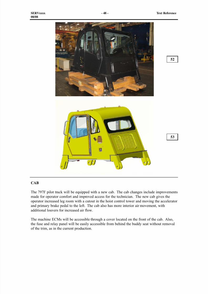
CAB
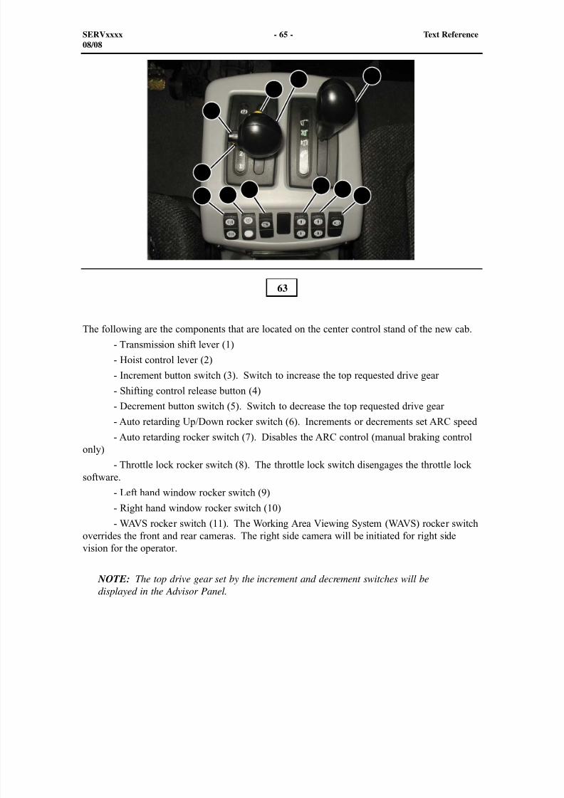
The 797F pilot truck will be equipped with a new cab. The cab changes include improvementsmade for operator comfort and improved access for the technician. The new cab gives theoperator increased leg room with a cutout in the hoist control tower and moving the acceleratorand primary brake pedal to the left. The cab also has more interior air movement, withadditional louvers for increased air flow.
The machine ECMs will be accessible through a cover located on the front of the cab. Also,the fuse and relay panel will be easily accessible from behind the buddy seat without removalof the trim, as in the current production.
52
53
SERVxxxx - 48 - Text Reference08/08

8/9/2019 797F HAA - Meeting Guide.pdf
http://slidepdf.com/reader/full/797f-haa-meeting-guidepdf 49/367
The new cab has the wiper location changed to increase the coverage on the windshield. Thenew cab has a 9.5 L (2.5 Gal) washer fluid bottle with a 25.4 mm (1 inch) diameter remotefill spout. The current production cab has a 5 L (1.3 Gal) washer fluid reservoir located undera removable cover, which equates to twice as many fillings. Also, a removable wiper motormount has increased the servicabilty for the technician.
An additional foot rest was added on the left side for the operator’s foot during operation of thetruck.
The air conditioning filter is accessible by removing thumb screw on the left side exterior panel. No tools will be required for service.
SERVxxxx - 49 - Text Reference08/08
8/9/2019 797F HAA - Meeting Guide.pdf
http://slidepdf.com/reader/full/797f-haa-meeting-guidepdf 50/367
54
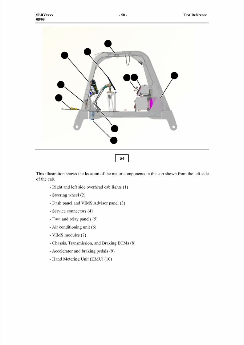
This illustration shows the location of the major components in the cab shown from the left sideof the cab.
- Right and left side overhead cab lights (1)
- Steering wheel (2)
- Dash panel and VIMS Advisor panel (3)
- Service connectors (4)
- Fuse and relay panels (5)
- Air conditioning unit (6)
- VIMS modules (7)
- Chassis, Transmission, and Braking ECMs (8)
- Accelerator and braking pedals (9)
- Hand Metering Unit (HMU) (10)
SERVxxxx - 50 - Text Reference08/08
3
2
6
7
8
9
1
4 5
10
8/9/2019 797F HAA - Meeting Guide.pdf
http://slidepdf.com/reader/full/797f-haa-meeting-guidepdf 51/367
1
2
4
3
5
55
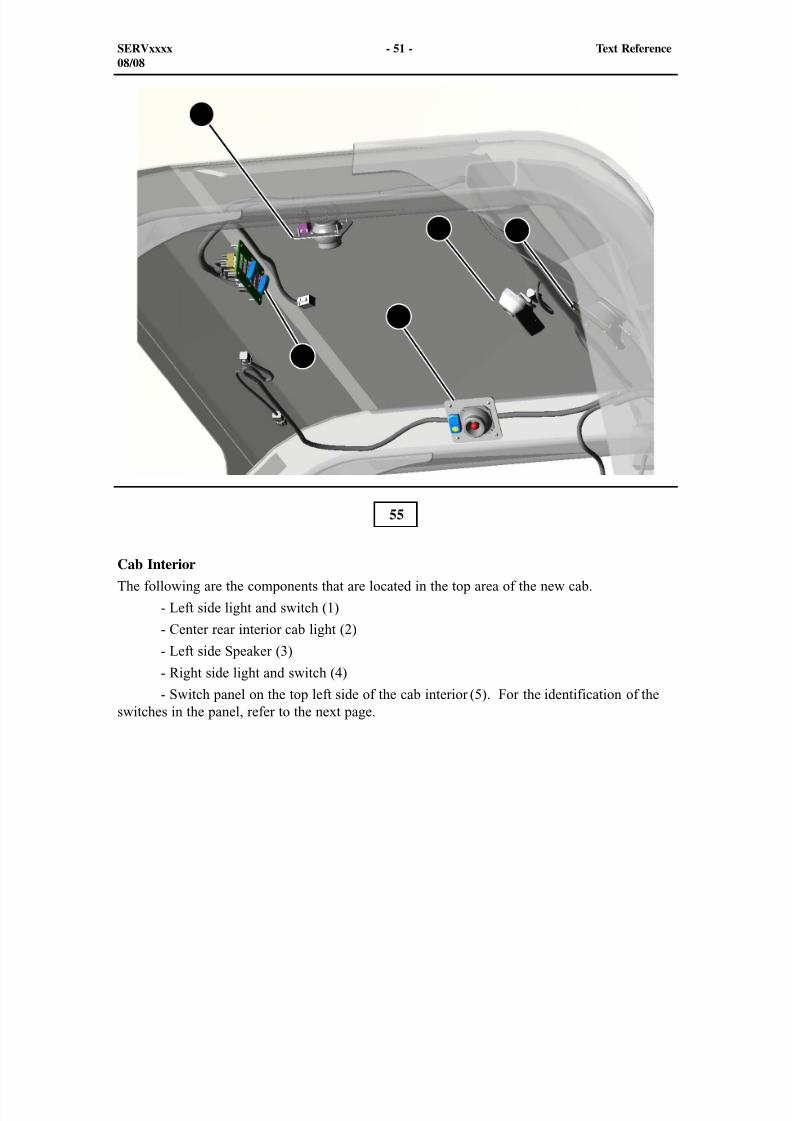
Cab Interior
The following are the components that are located in the top area of the new cab.
- Left side light and switch (1)
- Center rear interior cab light (2)
- Left side Speaker (3)
- Right side light and switch (4)
- Switch panel on the top left side of the cab interior (5). For the identification of theswitches in the panel, refer to the next page.
SERVxxxx - 51 - Text Reference08/08
8/9/2019 797F HAA - Meeting Guide.pdf
http://slidepdf.com/reader/full/797f-haa-meeting-guidepdf 52/367
1 2 3 4 5 6
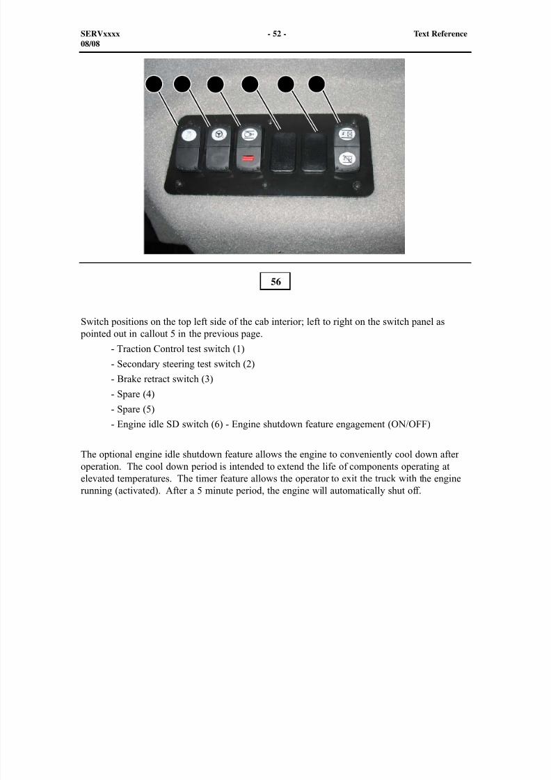
Switch positions on the top left side of the cab interior; left to right on the switch panel as pointed out in callout 5 in the previous page.
- Traction Control test switch (1)
- Secondary steering test switch (2)
- Brake retract switch (3) - Spare (4)
- Spare (5)
- Engine idle SD switch (6) - Engine shutdown feature engagement (ON/OFF)
The optional engine idle shutdown feature allows the engine to conveniently cool down afteroperation. The cool down period is intended to extend the life of components operating atelevated temperatures. The timer feature allows the operator to exit the truck with the enginerunning (activated). After a 5 minute period, the engine will automatically shut off.
56
SERVxxxx - 52 - Text Reference08/08
8/9/2019 797F HAA - Meeting Guide.pdf
http://slidepdf.com/reader/full/797f-haa-meeting-guidepdf 53/367
1 2
3
4
5
6
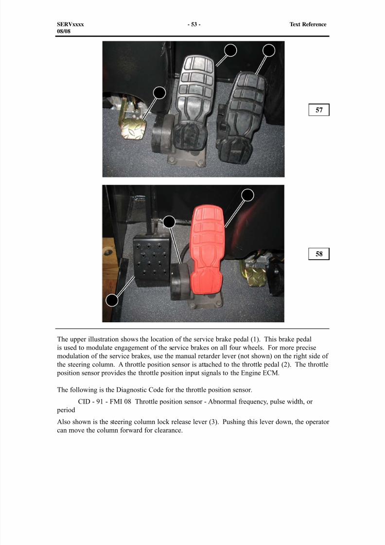
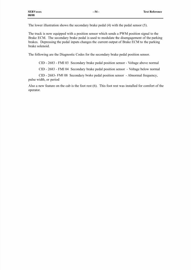
The upper illustration shows the location of the service brake pedal (1). This brake pedalis used to modulate engagement of the service brakes on all four wheels. For more precise
modulation of the service brakes, use the manual retarder lever (not shown) on the right side ofthe steering column. A throttle position sensor is attached to the throttle pedal (2). The throttle position sensor provides the throttle position input signals to the Engine ECM.
The following is the Diagnostic Code for the throttle position sensor.
CID - 91 - FMI 08 Throttle position sensor - Abnormal frequency, pulse width, or period
Also shown is the steering column lock release lever (3). Pushing this lever down, the operatorcan move the column forward for clearance.
57
58
SERVxxxx - 53 - Text Reference08/08
8/9/2019 797F HAA - Meeting Guide.pdf
http://slidepdf.com/reader/full/797f-haa-meeting-guidepdf 54/367
The lower illustration shows the secondary brake pedal (4) with the pedal sensor (5).
The truck is now equipped with a position sensor which sends a PWM position signal to theBrake ECM. The secondary brake pedal is used to modulate the disengagement of the parking
brakes. Depressing the pedal inputs changes the current output of Brake ECM to the parking brake solenoid.
The following are the Diagnostic Codes for the secondary brake pedal position sensor.
CID - 2683 - FMI 03 Secondary brake pedal position sensor - Voltage above normal
CID - 2683 - FMI 04 Secondary brake pedal position sensor - Voltage below normal
CID - 2683- FMI 08 Secondary brake pedal position sensor - Abnormal frequency, pulse width, or period
Also a new feature on the cab is the foot rest (6). This foot rest was installed for comfort of theoperator.
SERVxxxx - 54 - Text Reference08/08
8/9/2019 797F HAA - Meeting Guide.pdf
http://slidepdf.com/reader/full/797f-haa-meeting-guidepdf 55/367
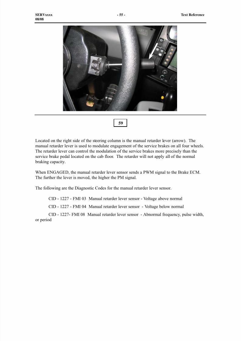
Located on the right side of the steering column is the manual retarder lever (arrow). Themanual retarder lever is used to modulate engagement of the service brakes on all four wheels.The retarder lever can control the modulation of the service brakes more precisely than theservice brake pedal located on the cab floor. The retarder will not apply all of the normal
braking capacity.
When ENGAGED, the manual retarder lever sensor sends a PWM signal to the Brake ECM.The further the lever is moved, the higher the PM signal.
The following are the Diagnostic Codes for the manual retarder lever sensor.
CID - 1227 - FMI 03 Manual retarder lever sensor - Voltage above normal
CID - 1227 - FMI 04 Manual retarder lever sensor - Voltage below normal
CID - 1227- FMI 08 Manual retarder lever sensor - Abnormal frequency, pulse width,or period
59
SERVxxxx - 55 - Text Reference08/08
8/9/2019 797F HAA - Meeting Guide.pdf
http://slidepdf.com/reader/full/797f-haa-meeting-guidepdf 56/367
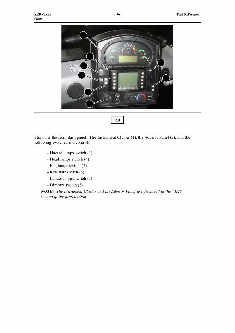
Shown is the front dash panel. The Instrument Cluster (1), the Advisor Panel (2), and thefollowing switches and controls.
- Hazard lamps switch (3)
- Head lamps switch (4)
- Fog lamps switch (5)
- Key start switch (6)
- Ladder lamps switch (7)
- Dimmer switch (8) NOTE: The Instrument Cluster and the Advisor Panel are discussed in the VIMSsection of the presentation.
60
SERVxxxx - 56 - Text Reference08/08
1
2
3
4
5
6
7
8
8/9/2019 797F HAA - Meeting Guide.pdf
http://slidepdf.com/reader/full/797f-haa-meeting-guidepdf 57/367
5
31 2
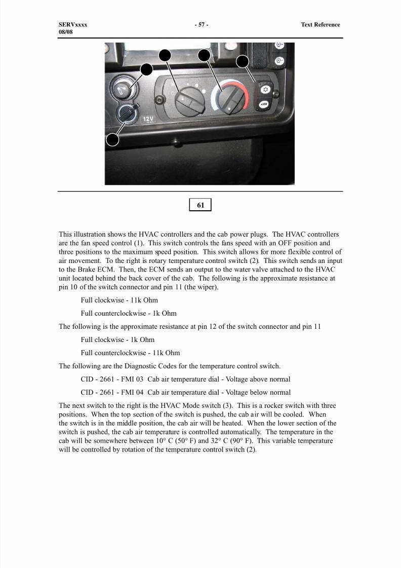
This illustration shows the HVAC controllers and the cab power plugs. The HVAC controllersare the fan speed control (1). This switch controls the fans speed with an OFF position andthree positions to the maximum speed position. This switch allows for more flexible control ofair movement. To the right is rotary temperature control switch (2). This switch sends an inputto the Brake ECM. Then, the ECM sends an output to the water valve attached to the HVAC
unit located behind the back cover of the cab. The following is the approximate resistance at pin 10 of the switch connector and pin 11 (the wiper).
Full clockwise - 11k Ohm
Full counterclockwise - 1k Ohm
The following is the approximate resistance at pin 12 of the switch connector and pin 11
Full clockwise - 1k Ohm
Full counterclockwise - 11k Ohm
The following are the Diagnostic Codes for the temperature control switch.
CID - 2661 - FMI 03 Cab air temperature dial - Voltage above normal
CID - 2661 - FMI 04 Cab air temperature dial - Voltage below normal
The next switch to the right is the HVAC Mode switch (3). This is a rocker switch with three positions. When the top section of the switch is pushed, the cab air will be cooled. Whenthe switch is in the middle position, the cab air will be heated. When the lower section of theswitch is pushed, the cab air temperature is controlled automatically. The temperature in thecab will be somewhere between 10° C (50° F) and 32° C (90° F). This variable temperaturewill be controlled by rotation of the temperature control switch (2).
61
SERVxxxx - 57 - Text Reference08/08
4

8/9/2019 797F HAA - Meeting Guide.pdf
http://slidepdf.com/reader/full/797f-haa-meeting-guidepdf 58/367
The following are the Diagnostic Codes for the HVAC Mode switch.
CID - 2659 - FMI 03 Cab air temperature control switch - Voltage above normal
CID - 2659 - FMI 04 Cab air temperature control switch - Voltage below normal
Also shown next to the HVAC controls are the cigarette lighter (4) and the 12 VDC supply (5).
SERVxxxx - 58 - Text Reference08/08
8/9/2019 797F HAA - Meeting Guide.pdf
http://slidepdf.com/reader/full/797f-haa-meeting-guidepdf 59/367
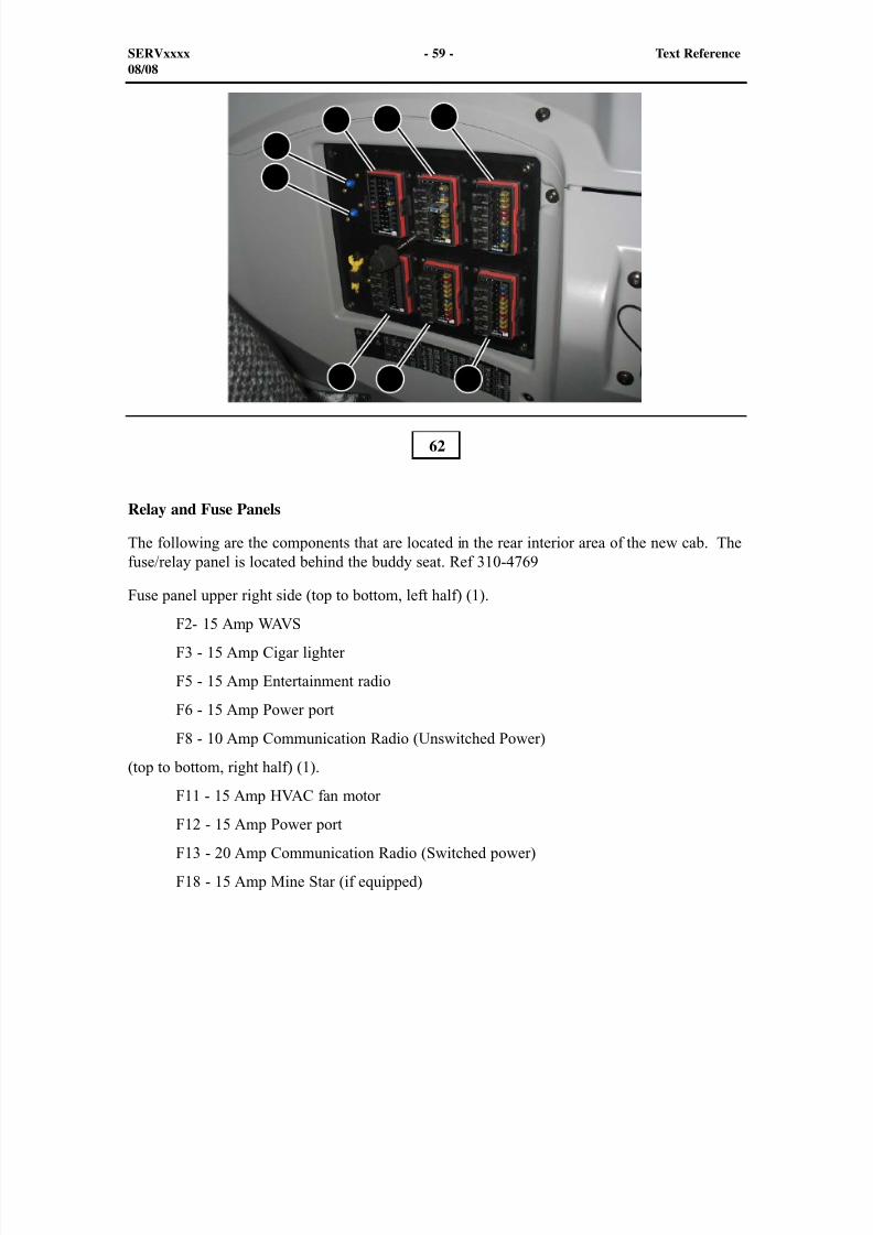
Relay and Fuse Panels
The following are the components that are located in the rear interior area of the new cab. Thefuse/relay panel is located behind the buddy seat. Ref 310-4769
Fuse panel upper right side (top to bottom, left half) (1).
F2- 15 Amp WAVS
F3 - 15 Amp Cigar lighter
F5 - 15 Amp Entertainment radio
F6 - 15 Amp Power port
F8 - 10 Amp Communication Radio (Unswitched Power)
(top to bottom, right half) (1).
F11 - 15 Amp HVAC fan motor
F12 - 15 Amp Power port
F13 - 20 Amp Communication Radio (Switched power)
F18 - 15 Amp Mine Star (if equipped)
62
SERVxxxx - 59 - Text Reference08/08
1 2 3
6 7 8
4
5
8/9/2019 797F HAA - Meeting Guide.pdf
http://slidepdf.com/reader/full/797f-haa-meeting-guidepdf 60/367
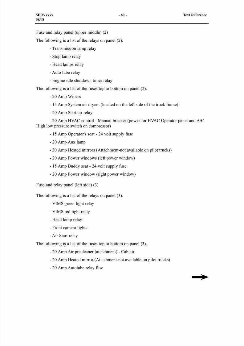
Fuse and relay panel (upper middle) (2)
The following is a list of the relays on panel (2).
- Transmission lamp relay
- Stop lamp relay- Head lamps relay
- Auto lube relay
- Engine idle shutdown timer relay
The following is a list of the fuses top to bottom on panel (2).
- 20 Amp Wipers
- 15 Amp System air dryers (located on the left side of the truck frame)
- 20 Amp Start air relay - 20 Amp HVAC control - Manual breaker (power for HVAC Operator panel and A/CHigh low pressure switch on compressor)
- 15 Amp Operator's seat - 24 volt supply fuse
- 20 Amp Aux lamp
- 20 Amp Heated mirrors (Attachment-not available on pilot trucks)
- 20 Amp Power windows (left power window)
- 15 Amp Buddy seat - 24 volt supply fuse
- 20 Amp Power window (right power window)
Fuse and relay panel (left side) (3)
The following is a list of the relays on panel (3).
- VIMS green light relay
- VIMS red light relay
- Head lamp relay
- Front camera lights
- Air Start relay
The following is a list of the fuses top to bottom on panel (3).
- 20 Amp Air precleaner (attachment) - Cab air
- 20 Amp Heated mirror (Attachment-not available on pilot trucks)
- 20 Amp Autolube relay fuse
SERVxxxx - 60 - Text Reference08/08
8/9/2019 797F HAA - Meeting Guide.pdf
http://slidepdf.com/reader/full/797f-haa-meeting-guidepdf 61/367
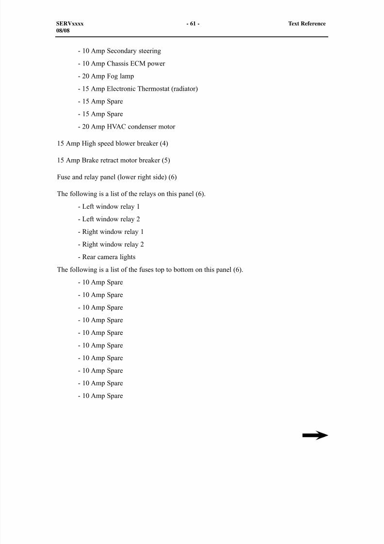
- 10 Amp Secondary steering
- 10 Amp Chassis ECM power
- 20 Amp Fog lamp
- 15 Amp Electronic Thermostat (radiator) - 15 Amp Spare
- 15 Amp Spare
- 20 Amp HVAC condenser motor
15 Amp High speed blower breaker (4)
15 Amp Brake retract motor breaker (5)
Fuse and relay panel (lower right side) (6)
The following is a list of the relays on this panel (6).
- Left window relay 1
- Left window relay 2
- Right window relay 1
- Right window relay 2
- Rear camera lights
The following is a list of the fuses top to bottom on this panel (6).
- 10 Amp Spare
- 10 Amp Spare
- 10 Amp Spare
- 10 Amp Spare
- 10 Amp Spare
- 10 Amp Spare
- 10 Amp Spare
- 10 Amp Spare
- 10 Amp Spare
- 10 Amp Spare
SERVxxxx - 61 - Text Reference08/08
8/9/2019 797F HAA - Meeting Guide.pdf
http://slidepdf.com/reader/full/797f-haa-meeting-guidepdf 62/367
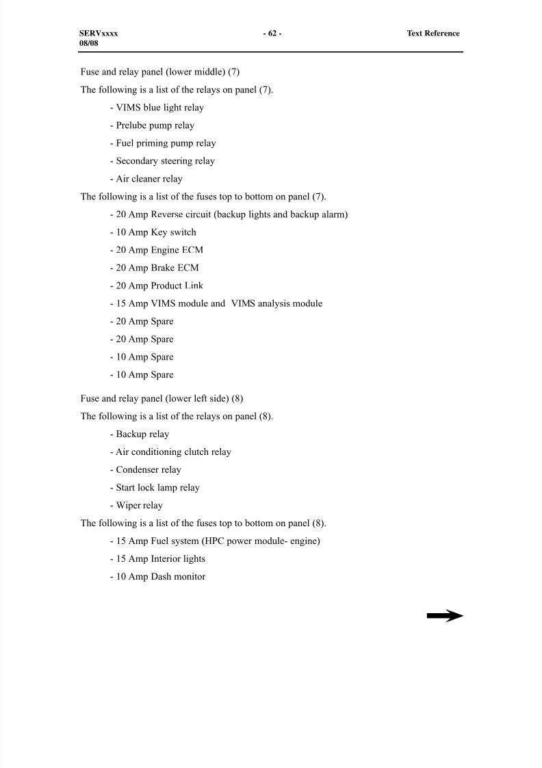
Fuse and relay panel (lower middle) (7)
The following is a list of the relays on panel (7).
- VIMS blue light relay
- Prelube pump relay - Fuel priming pump relay
- Secondary steering relay
- Air cleaner relay
The following is a list of the fuses top to bottom on panel (7).
- 20 Amp Reverse circuit (backup lights and backup alarm)
- 10 Amp Key switch
- 20 Amp Engine ECM - 20 Amp Brake ECM
- 20 Amp Product Link
- 15 Amp VIMS module and VIMS analysis module
- 20 Amp Spare
- 20 Amp Spare
- 10 Amp Spare
- 10 Amp Spare
Fuse and relay panel (lower left side) (8)
The following is a list of the relays on panel (8).
- Backup relay
- Air conditioning clutch relay
- Condenser relay
- Start lock lamp relay
- Wiper relay
The following is a list of the fuses top to bottom on panel (8).
- 15 Amp Fuel system (HPC power module- engine)
- 15 Amp Interior lights
- 10 Amp Dash monitor
SERVxxxx - 62 - Text Reference08/08

8/9/2019 797F HAA - Meeting Guide.pdf
http://slidepdf.com/reader/full/797f-haa-meeting-guidepdf 63/367
- 20 Amp Transmission ECM
- 20 Amp 24 to 12 VDC converter
- 20 Amp Chassis ECM
- 10 Amp Horn - 20 Amp Spare
- 20 Amp Spare
- 10 Amp Spare
SERVxxxx - 63 - Text Reference08/08
8/9/2019 797F HAA - Meeting Guide.pdf
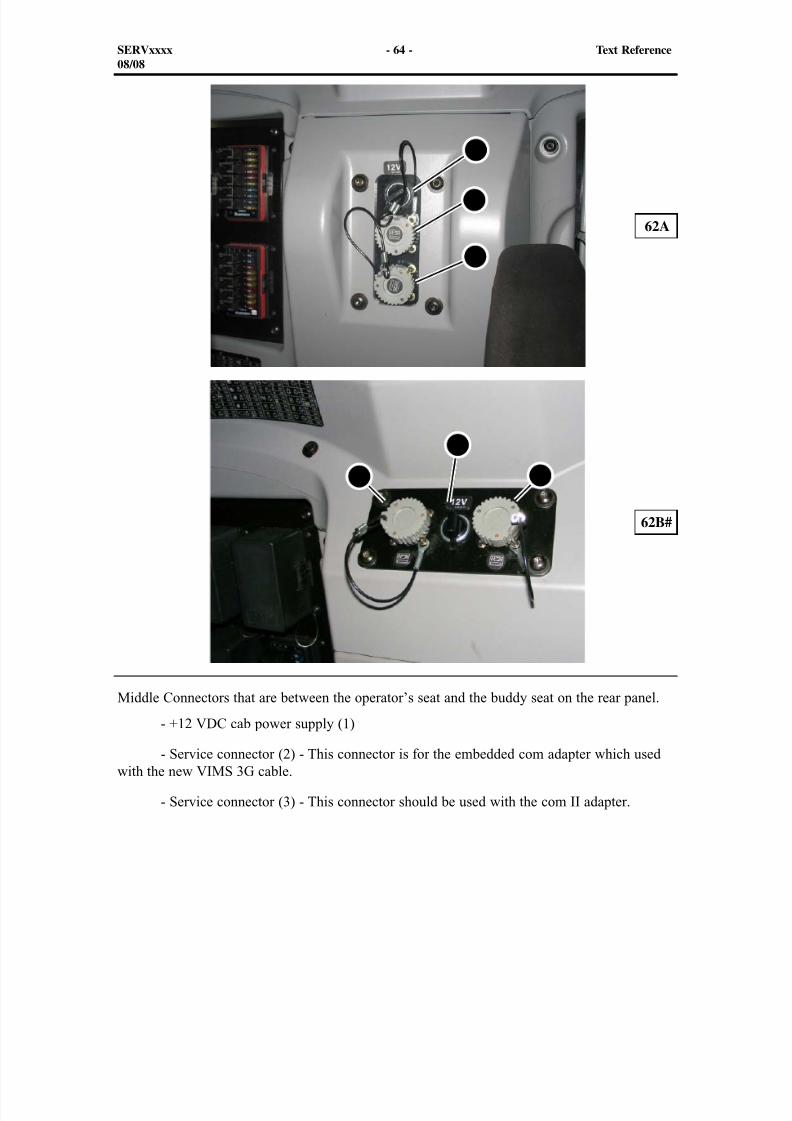
http://slidepdf.com/reader/full/797f-haa-meeting-guidepdf 64/367
8/9/2019 797F HAA - Meeting Guide.pdf
http://slidepdf.com/reader/full/797f-haa-meeting-guidepdf 65/367
8/9/2019 797F HAA - Meeting Guide.pdf
http://slidepdf.com/reader/full/797f-haa-meeting-guidepdf 66/367
1
2 3 4
5 6
7
64
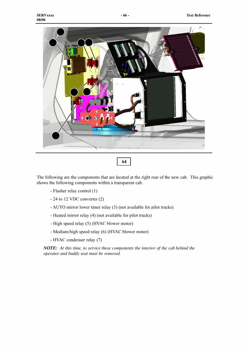
The following are the components that are located at the right rear of the new cab. This graphicshows the following components within a transparent cab.
- Flasher relay control (1)
- 24 to 12 VDC converter (2)
- AUTO mirror lower timer relay (3) (not available for pilot trucks)
- Heated mirror relay (4) (not available for pilot trucks)
- High speed relay (5) (HVAC blower motor)
- Medium/high speed relay (6) (HVAC blower motor)
- HVAC condenser relay (7)
NOTE: At this time, to service these components the interior of the cab behind theoperator and buddy seat must be removed.
SERVxxxx - 66 - Text Reference08/08
8/9/2019 797F HAA - Meeting Guide.pdf
http://slidepdf.com/reader/full/797f-haa-meeting-guidepdf 67/367
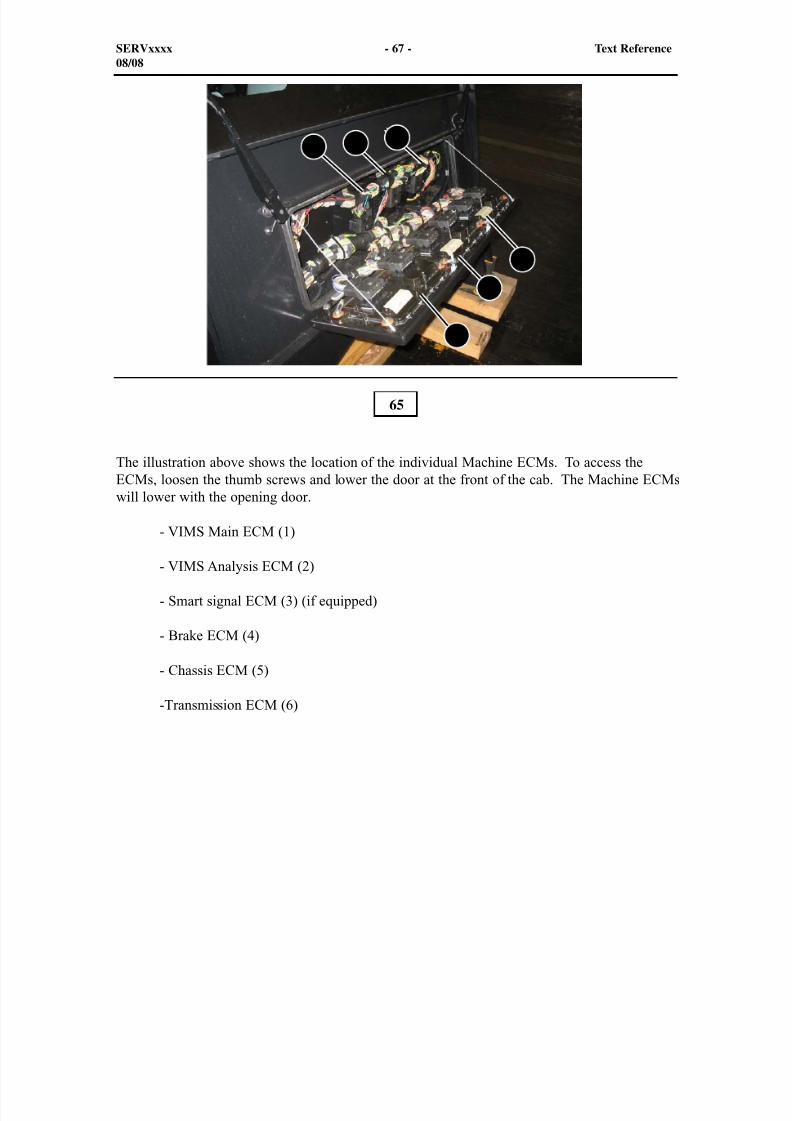
The illustration above shows the location of the individual Machine ECMs. To access theECMs, loosen the thumb screws and lower the door at the front of the cab. The Machine ECMswill lower with the opening door.
- VIMS Main ECM (1)
- VIMS Analysis ECM (2)
- Smart signal ECM (3) (if equipped)
- Brake ECM (4)
- Chassis ECM (5)
-Transmission ECM (6)
65
SERVxxxx - 67 - Text Reference08/08
1 2 3
4
5
6
8/9/2019 797F HAA - Meeting Guide.pdf
http://slidepdf.com/reader/full/797f-haa-meeting-guidepdf 68/367
1
2
3
4
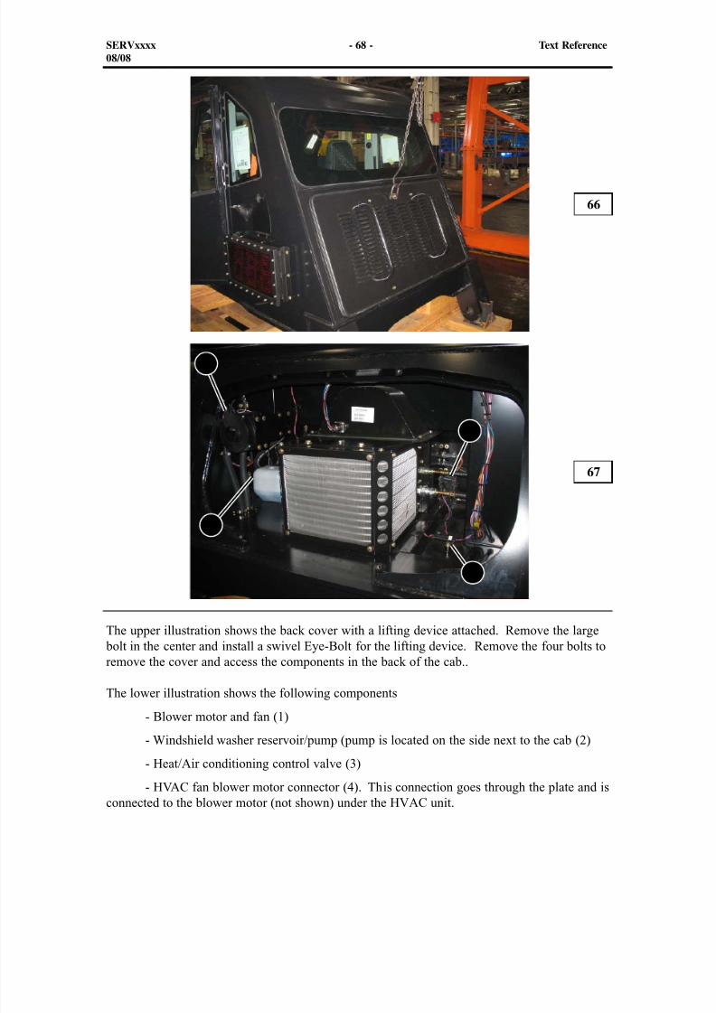
The upper illustration shows the back cover with a lifting device attached. Remove the large bolt in the center and install a swivel Eye-Bolt for the lifting device. Remove the four bolts to
remove the cover and access the components in the back of the cab..
The lower illustration shows the following components
- Blower motor and fan (1)
- Windshield washer reservoir/pump (pump is located on the side next to the cab (2)
- Heat/Air conditioning control valve (3)
- HVAC fan blower motor connector (4). This connection goes through the plate and isconnected to the blower motor (not shown) under the HVAC unit.
66
67
SERVxxxx - 68 - Text Reference08/08
8/9/2019 797F HAA - Meeting Guide.pdf
http://slidepdf.com/reader/full/797f-haa-meeting-guidepdf 69/367
1
2
3
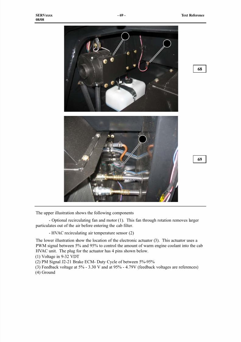
The upper illustration shows the following components
- Optional recirculating fan and motor (1). This fan through rotation removes larger particulates out of the air before entering the cab filter.
- HVAC recirculating air temperature sensor (2)
The lower illustration show the location of the electronic actuator (3). This actuator uses aPWM signal between 5% and 95% to control the amount of warm engine coolant into the cabHVAC unit. The plug for the actuator has 4 pins shown below.
68
69
SERVxxxx - 69 - Text Reference08/08
(1) Voltage in 9-32 VDT(2) PM Signal J2-21 Brake ECM- Duty Cycle of between 5%-95%(3) Feedback voltage at 5% - 3.30 V and at 95% - 4.79V (feedback voltages are references)(4) Ground

8/9/2019 797F HAA - Meeting Guide.pdf
http://slidepdf.com/reader/full/797f-haa-meeting-guidepdf 70/367
This electronic actuator is being used along with the A/C compressor to maintain an operatordesired temperature. The automatic temperature control will maintain the operator's desiredtemperature. The cab will be cooled down or heated up depending on operator's demand.
In the absence of an automatic temperature control configuration, the open loop temperaturecontrol feature will open loop control the position of the water valve actuator based on the
position of the temperature control switch on the front dash panel.
SERVxxxx - 70 - Text Reference08/08
8/9/2019 797F HAA - Meeting Guide.pdf
http://slidepdf.com/reader/full/797f-haa-meeting-guidepdf 71/367
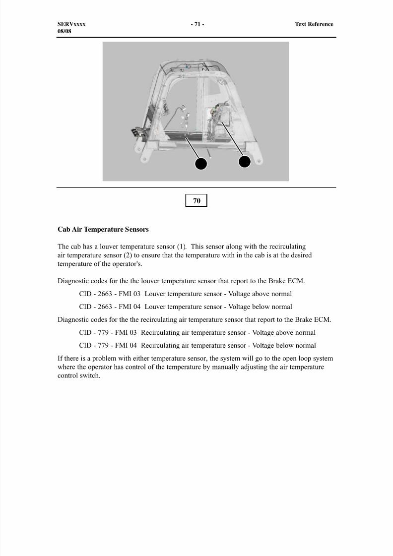
Cab Air Temperature Sensors
The cab has a louver temperature sensor (1). This sensor along with the recirculatingair temperature sensor (2) to ensure that the temperature with in the cab is at the desiredtemperature of the operator's.
Diagnostic codes for the the louver temperature sensor that report to the Brake ECM.
CID - 2663 - FMI 03 Louver temperature sensor - Voltage above normal
CID - 2663 - FMI 04 Louver temperature sensor - Voltage below normal
Diagnostic codes for the the recirculating air temperature sensor that report to the Brake ECM.
CID - 779 - FMI 03 Recirculating air temperature sensor - Voltage above normal
CID - 779 - FMI 04 Recirculating air temperature sensor - Voltage below normal
If there is a problem with either temperature sensor, the system will go to the open loop systemwhere the operator has control of the temperature by manually adjusting the air temperaturecontrol switch.
70
SERVxxxx - 71 - Text Reference08/08
1 2
8/9/2019 797F HAA - Meeting Guide.pdf
http://slidepdf.com/reader/full/797f-haa-meeting-guidepdf 72/367
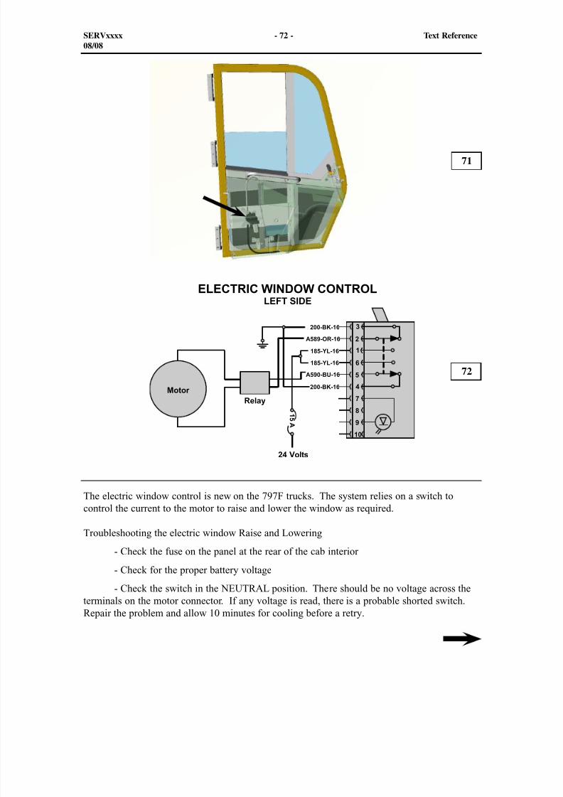
The electric window control is new on the 797F trucks. The system relies on a switch tocontrol the current to the motor to raise and lower the window as required.
Troubleshooting the electric window Raise and Lowering
- Check the fuse on the panel at the rear of the cab interior
- Check for the proper battery voltage
- Check the switch in the NEUTRAL position. There should be no voltage across theterminals on the motor connector. If any voltage is read, there is a probable shorted switch.Repair the problem and allow 10 minutes for cooling before a retry.
71
72
SERVxxxx - 72 - Text Reference08/08
8/9/2019 797F HAA - Meeting Guide.pdf
http://slidepdf.com/reader/full/797f-haa-meeting-guidepdf 73/367
- Depress the rocker switch in the Lower position and verify system voltage. Then,depress the rocker switch in the raise position. If either position fails to produce systemvoltage, check the switch for failure and replace the switch if necessary.
- If both switch position movements produce system voltage, remove the screws thatmounts the window to the frame. Raise and lower the window. If the glass moves up anddown freely, try the motor for operation. If the motor shaft rotates, reconnect the screws butleave the screws loose so the glass is free to move side to side within the mounting channels.If the motor moves freely, loosen the regulator mounting hardware. Adjust the mountinghardware if necessary and retry to operate the windows. If the windows and regulator areworking properly, tighten up the mounting screws and retry. If the window regulator fails tomove with the windows loose, let the motor cool for 10 minutes and retry.
- At this time, if the window still doesn’t operate correctly, remove and replace thewindow regulator.
NOTE: The regulator assembly is equipped with a thermal protection circuit to protectthe motor from damage. Depending on air temperature, window load, and usage, themotor may trip after several cycles. Consider this normal and not to be a defectiveregulator. Allow to cool for 10 minutes to reset the thermal protection between testing.
SERVxxxx - 73 - Text Reference08/08
8/9/2019 797F HAA - Meeting Guide.pdf
http://slidepdf.com/reader/full/797f-haa-meeting-guidepdf 74/367
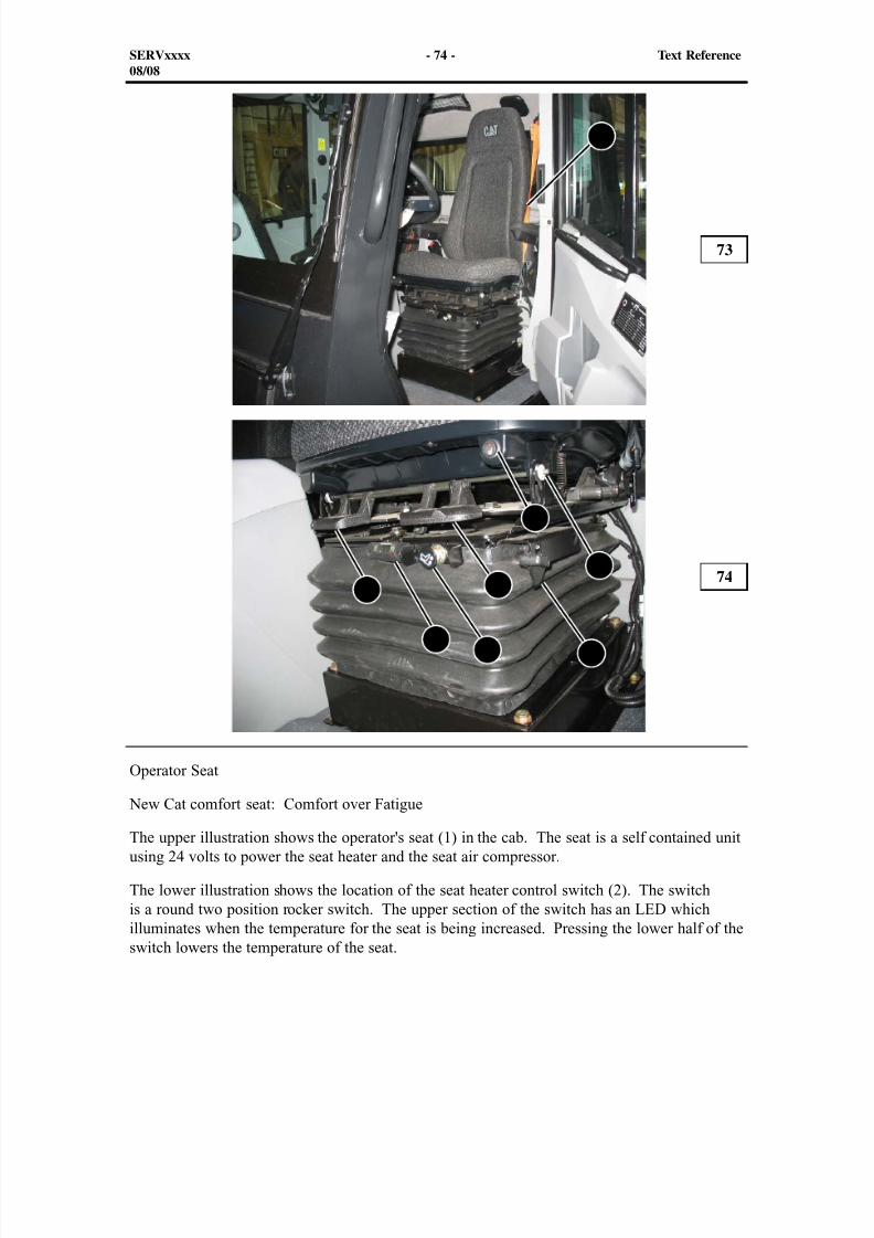
Operator Seat
New Cat comfort seat: Comfort over FatigueThe upper illustration shows the operator's seat (1) in the cab. The seat is a self contained unitusing 24 volts to power the seat heater and the seat air compressor.
The lower illustration shows the location of the seat heater control switch (2). The switchis a round two position rocker switch. The upper section of the switch has an LED whichilluminates when the temperature for the seat is being increased. Pressing the lower half of theswitch lowers the temperature of the seat.
73
74
SERVxxxx - 74 - Text Reference08/08
1
2
3 4
5
7
68
8/9/2019 797F HAA - Meeting Guide.pdf
http://slidepdf.com/reader/full/797f-haa-meeting-guidepdf 75/367
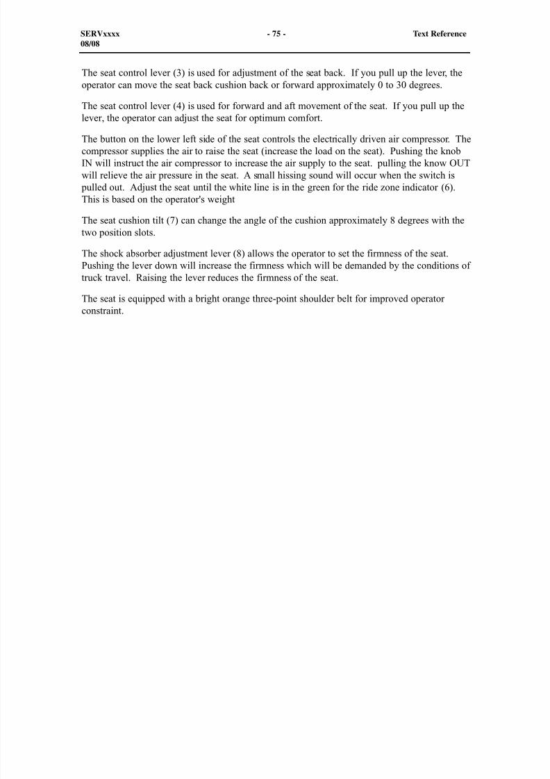
The seat control lever (3) is used for adjustment of the seat back. If you pull up the lever, theoperator can move the seat back cushion back or forward approximately 0 to 30 degrees.
The seat control lever (4) is used for forward and aft movement of the seat. If you pull up thelever, the operator can adjust the seat for optimum comfort.
The button on the lower left side of the seat controls the electrically driven air compressor. Thecompressor supplies the air to raise the seat (increase the load on the seat). Pushing the knobIN will instruct the air compressor to increase the air supply to the seat. pulling the know OUTwill relieve the air pressure in the seat. A small hissing sound will occur when the switch is
pulled out. Adjust the seat until the white line is in the green for the ride zone indicator (6).This is based on the operator's weight
The seat cushion tilt (7) can change the angle of the cushion approximately 8 degrees with thetwo position slots.
The shock absorber adjustment lever (8) allows the operator to set the firmness of the seat.Pushing the lever down will increase the firmness which will be demanded by the conditions oftruck travel. Raising the lever reduces the firmness of the seat.
The seat is equipped with a bright orange three-point shoulder belt for improved operatorconstraint.
SERVxxxx - 75 - Text Reference08/08
8/9/2019 797F HAA - Meeting Guide.pdf
http://slidepdf.com/reader/full/797f-haa-meeting-guidepdf 76/367
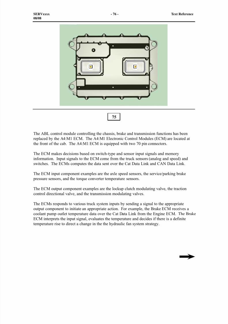
The ABL control module controlling the chassis, brake and transmission functions has beenreplaced by the A4:M1 ECM. The A4:M1 Electronic Control Modules (ECM) are located atthe front of the cab. The A4:M1 ECM is equipped with two 70 pin connectors.
The ECM makes decisions based on switch-type and sensor input signals and memory
information. Input signals to the ECM come from the truck sensors (analog and speed) andswitches. The ECMs computes the data sent over the Cat Data Link and CAN Data Link.
The ECM input component examples are the axle speed sensors, the service/parking brake pressure sensors, and the torque converter temperature sensors.
The ECM output component examples are the lockup clutch modulating valve, the tractioncontrol directional valve, and the transmission modulating valves.
The ECMs responds to various truck system inputs by sending a signal to the appropriateoutput component to initiate an appropriate action. For example, the Brake ECM receives acoolant pump outlet temperature data over the Cat Data Link from the Engine ECM. The BrakeECM interprets the input signal, evaluates the temperature and decides if there is a definitetemperature rise to direct a change in the the hydraulic fan system strategy.
75
SERVxxxx - 76 - Text Reference08/08
8/9/2019 797F HAA - Meeting Guide.pdf
http://slidepdf.com/reader/full/797f-haa-meeting-guidepdf 77/367
The A4:M1 ECMs receives three different types of input signals:
1. Switch input: Provides the signal line to battery, ground, or open.
2. PWM input: Provides the signal line with a square wave of a specific frequency and avarying positive duty cycle.
3. Speed signal: Provides the signal line with either a repeating, fixed voltage level patternsignal or a sine wave of varying level and frequency.
The A4:M1 ECMs has three types of output drivers:
1. ON/OFF driver: Provides the output device with a signal level of +Battery voltage(ON) or less than one Volt (OFF).
2. PWM driver: Provides the output device with a square wave of fixed frequency and avarying positive duty cycle.
3. Controlled current output driver: The ECM will energize the solenoid with pull-upcurrent for a specific duration and then decrease the level to hold-in current for a specificduration of the on time. The initial higher amperage gives the actuator rapid responseand the decreased level is sufficient to hold the solenoid in the correct position. An added
benefit is an increase in the life of the solenoid.
The A4:M1 ECM has built-in diagnostic capabilities. As the ECMs detects fault conditions inthe power train system (for example), the ECM logs events in memory and diagnostic codes fortroubleshooting and displays them through Caterpillar Electronic Technician (ET).
SERVxxxx - 77 - Text Reference08/08
8/9/2019 797F HAA - Meeting Guide.pdf
http://slidepdf.com/reader/full/797f-haa-meeting-guidepdf 78/367
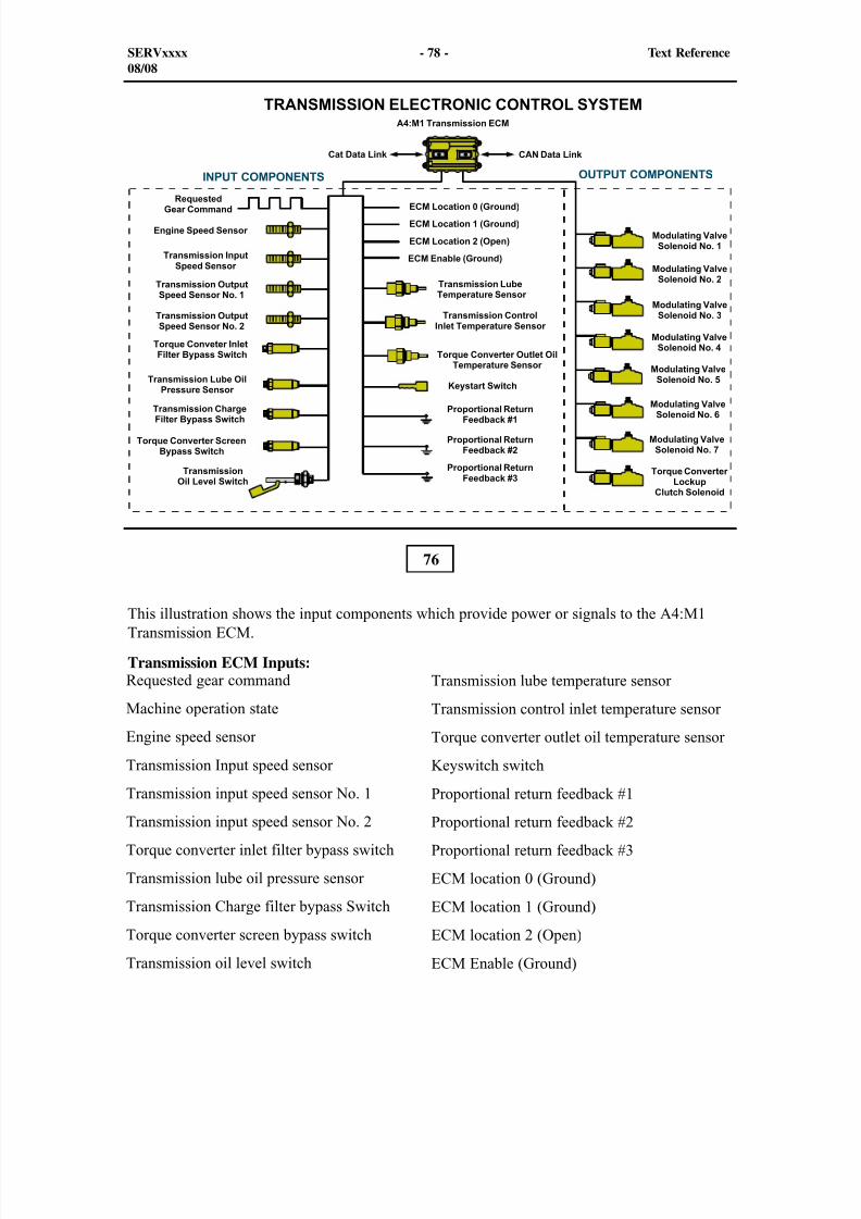
76
This illustration shows the input components which provide power or signals to the A4:M1Transmission ECM.
Transmission ECM Inputs:
SERVxxxx - 78 - Text Reference08/08
Requested gear command
Machine operation state
Engine speed sensor
Transmission Input speed sensor
Transmission input speed sensor No. 1Transmission input speed sensor No. 2
Torque converter inlet filter bypass switch
Transmission lube oil pressure sensor
Transmission Charge filter bypass Switch
Torque converter screen bypass switch
Transmission oil level switch
Transmission lube temperature sensor
Transmission control inlet temperature sensor
Torque converter outlet oil temperature sensor
Keyswitch switch
Proportional return feedback #1Proportional return feedback #2
Proportional return feedback #3
ECM location 0 (Ground)
ECM location 1 (Ground)
ECM location 2 (Open)
ECM Enable (Ground)
8/9/2019 797F HAA - Meeting Guide.pdf
http://slidepdf.com/reader/full/797f-haa-meeting-guidepdf 79/367
In order to enable the Transmission ECM, All Three of the appropriate location code inputsmust be grounded to run. When the ECM has J1-26, J1-27 and J1-32 pins grounded, themonitoring system recognizes the ECM as the transmission control. With any problems withthe inputs for the location codes, the transmission ECM will activate the following DiagnosticCode.
MID 051 - CID - 1326 - FMI 02 ECM Location Code - Incorrect, invalid, or erraticsignal
The proportional return feedback inputs to the Transmission ECM are used by to warn theECM of a problem with the solenoid coil or a harness problem. If one of the solenoids returnloses its path to the Transmission ECM, the ECM will receive a PWM input to the ECM. Ifa return to ECM for one of the solenoid (modulating) valves is open, the ECM has no way todetermine an OPEN. With an open to one of the solenoid valve return, the transmission shiftstrategy will not allow the transmission control to engage any gear that is related a solenoid
valve with a lost solenoid return.
Solenoid proportional return feedback Modulating valve (1), (4), and the T/C lockup clutch
- Diagnostic Code for return wire H801
- MID - 81 CID - 1674 FMI - 03 - Solenoid Return #1 - Voltage above normal
Solenoid proportional return feedback Modulating valve (2), (5), and (7)
- Diagnostic Code for return wire H802
- MID - 81 CID - 1675 FMI - 03 - Solenoid Return #2 - Voltage above normal
Solenoid proportional return feedback Modulating valve (3), and (6)
- Diagnostic Code for return wire H803 - MID - 81 CID - 1676 FMI - 03 - Solenoid Return #3 - Voltage above normal
Transmission ECM Outputs:
Modulating Valve No. 1
Modulating Valve No. 2
Modulating Valve No. 3
Modulating Valve No. 4
Modulating Valve No. 5
Modulating Valve No. 6
Modulating Valve No. 7
Torque Converter lockup clutch solenoid
SERVxxxx - 79 - Text Reference08/08
8/9/2019 797F HAA - Meeting Guide.pdf
http://slidepdf.com/reader/full/797f-haa-meeting-guidepdf 80/367
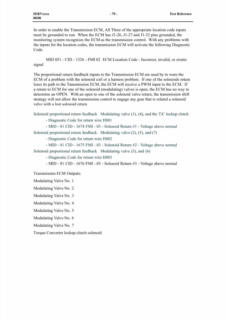
77
This illustration shows the input components which provide power or signals to the A4:M1Brake ECM.
Brake ECM Inputs:
SERVxxxx - 80 - Text Reference08/08
Requested gear command
Machine operation state
Engine speed sensor
Brake cooling speed sensor
Engine fan speed sensor Left rear wheel speed sensor
Right rear wheel speed sensor
Service brake accumulator pressure sensor
Parking brake accumulator pressure sensor
Service brake pressure switch
Parking brake pressure switch
Differential filter bypass switch
Brake pump pressure sensor
Differential lube pressure sensor
Differential lube pressure sensor
Brake pump pressure sensor Final drive lube oil pressure switch
A/C low pressure switch
ARC speed switch
TCS test Switch
ARC ON/OFF switch
A/C mode switch
8/9/2019 797F HAA - Meeting Guide.pdf
http://slidepdf.com/reader/full/797f-haa-meeting-guidepdf 81/367
In order to enable the Brake ECM, Both of theappropriate location code inputs must be grounded to run. When the ECM has J1-27 and J1-32 pins grounded, the monitoring system recognizes this ECM as the brake control. With any
problems with the inputs for the location codes, the Brake ECM will activate the followingDiagnostic Code.
MID 074 - CID - 1326 - FMI 02 ECM Location Code - Incorrect, invalid, or erratic
signal
Brake ECM Outputs:
SERVxxxx - 81 - Text Reference08/08
Parking brake ON/OFF switch
Retarding speed +/-
Secondary brake pedal position sensor
Retarder lever position sensor Brake filter bypass switch
Final drive filter bypass switch
Fan drive oil filter switch
ECM Location Mode 0 (Open)
ECM Location Mode 1 (Ground)
ECM Location Mode 2 (Open)
ECM Enable (Open)
Keystart switch
Brake oil temperature sensors
Cab air temperature sensor
Cab ventilation temperature sensor Rear differential temperature sensor
Brake cooling filter switch RH
Brake cooling filter switch LH
TCS left and right brake solenoids
TCS proportional solenoid
Final drive oil bypass solenoid
ARC front control solenoid
Brake cooling diverter solenoid RAXL cooler solenoid
ARC Rear control solenoid
A/C compressor clutch relay
A/C Condenser relay
Brake light relay
Brake unloader solenoid
Rear axle pump drive oil diverter solenoid
Brake cooling pump drive solenoid
Engine cooling fan solenoid
Final drive oil bypass solenoid Park brake solenoid
8/9/2019 797F HAA - Meeting Guide.pdf
http://slidepdf.com/reader/full/797f-haa-meeting-guidepdf 82/367
8/9/2019 797F HAA - Meeting Guide.pdf
http://slidepdf.com/reader/full/797f-haa-meeting-guidepdf 83/367
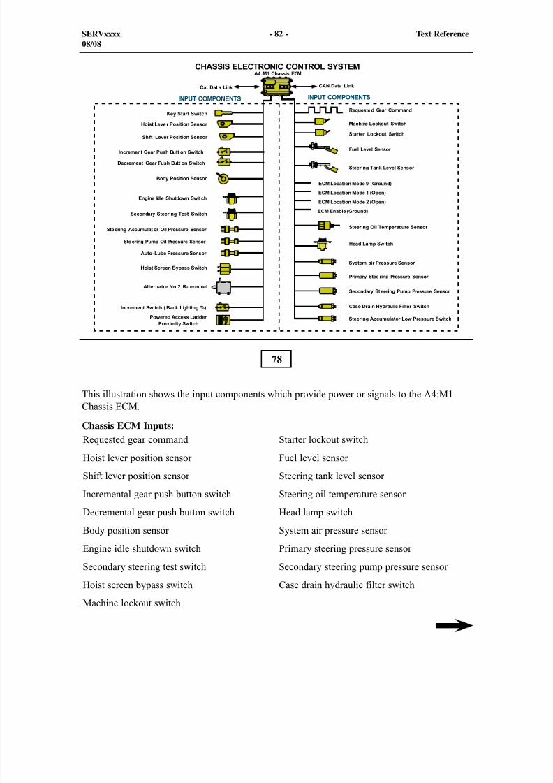
ECM Location Mode 0 (Ground)
ECM Location Mode 1 (Open)
ECM Location Mode 2 (Open)
ECM Enable (Open)
In order to enable the Chassis ECM, Both of the appropriate location code inputs must begrounded to run. When the ECM has J1-26, and J1-32 pins grounded, the monitoring systemrecognizes the ECM as the chassis control. With any problems with the inputs for the locationcodes, the Chassis ECM will activate the following Diagnostic Code.
MID 057 - CID - 1326 - FMI 02 ECM Location Code - Incorrect, invalid, or erraticsignal
SERVxxxx - 83 - Text Reference08/08
Alternator No. 2 R-terminal
Incremental switch (back lighting)
Steering accumulator low pressure switch
Powered ladder proximity switch
8/9/2019 797F HAA - Meeting Guide.pdf
http://slidepdf.com/reader/full/797f-haa-meeting-guidepdf 84/367
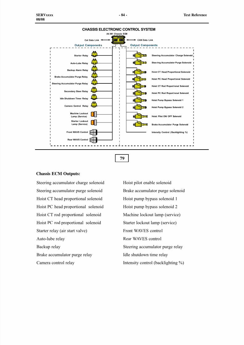
79
Chassis ECM Outputs:
SERVxxxx - 84 - Text Reference08/08
Steering accumulator charge solenoid
Steering accumulator purge solenoid
Hoist CT head proportional solenoid
Hoist PC head proportional solenoid
Hoist CT rod proportional solenoid
Hoist PC rod proportional solenoid
Starter relay (air start valve)
Auto-lube relay
Backup relay
Brake accumulator purge relay
Camera control relay
Hoist pilot enable solenoid
Brake accumulator purge solenoid
Hoist pump bypass solenoid 1
Hoist pump bypass solenoid 2
Machine lockout lamp (service)
Starter lockout lamp (service)
Front WAVES control
Rear WAVES control
Steering accumulator purge relay
Idle shutdown time relay
Intensity control (backlighting %)
8/9/2019 797F HAA - Meeting Guide.pdf
http://slidepdf.com/reader/full/797f-haa-meeting-guidepdf 85/367
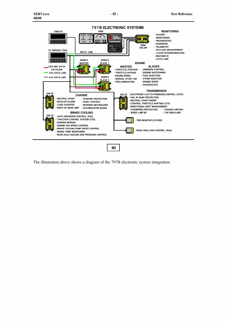
80
The illustration above shows a diagram of the 797B electronic system integration.
SERVxxxx - 85 - Text Reference08/08
8/9/2019 797F HAA - Meeting Guide.pdf
http://slidepdf.com/reader/full/797f-haa-meeting-guidepdf 86/367
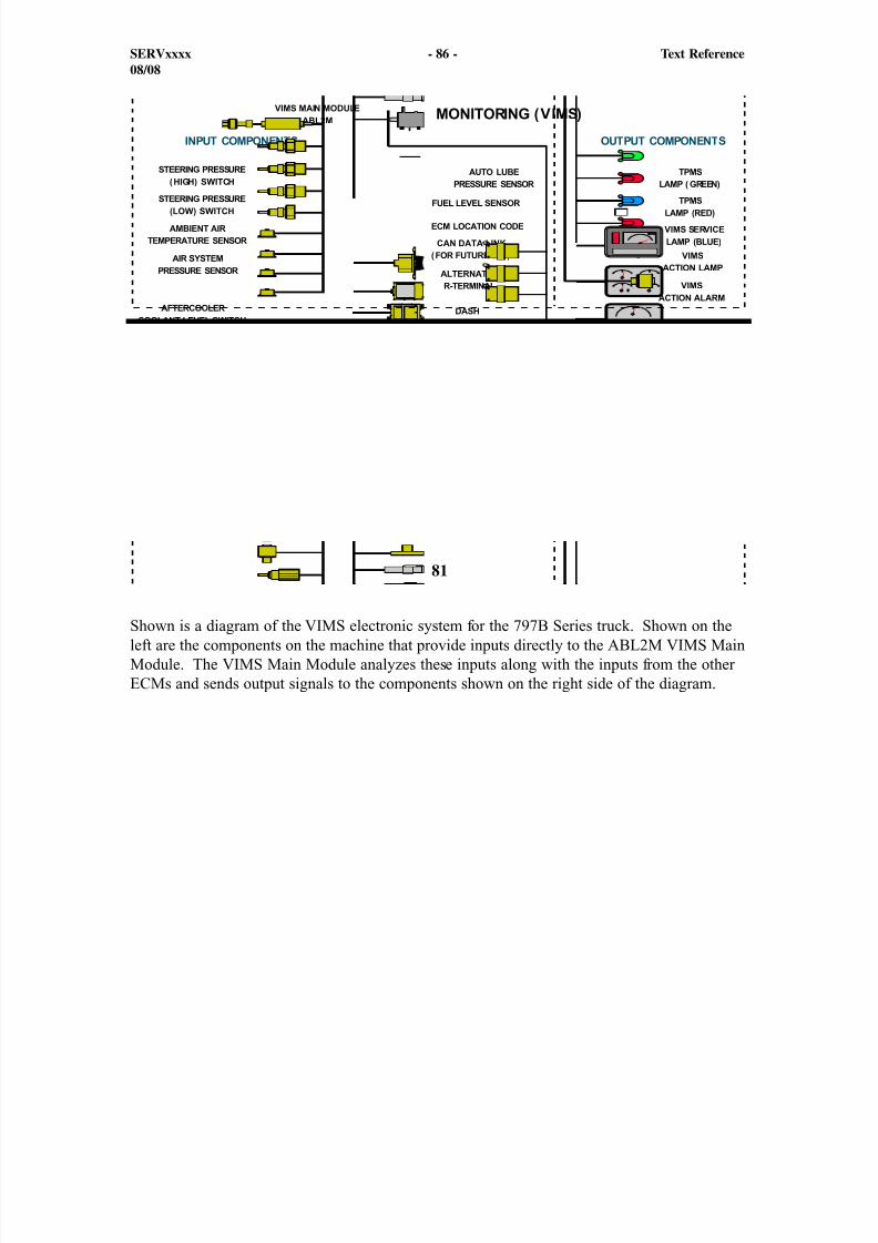
81
Shown is a diagram of the VIMS electronic system for the 797B Series truck. Shown on theleft are the components on the machine that provide inputs directly to the ABL2M VIMS MainModule. The VIMS Main Module analyzes these inputs along with the inputs from the otherECMs and sends output signals to the components shown on the right side of the diagram.
SERVxxxx - 86 - Text Reference08/08
8/9/2019 797F HAA - Meeting Guide.pdf
http://slidepdf.com/reader/full/797f-haa-meeting-guidepdf 87/367
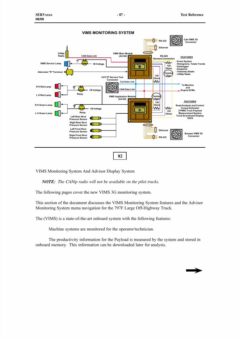
82
VIMS Monitoring System And Advisor Display System
NOTE: The CANip radio will not be available on the pilot trucks.
The following pages cover the new VIMS 3G monitoring system.
This section of the document discusses the VIMS Monitoring System features and the AdvisorMonitoring System menu navigation for the 797F Large Off-Highway Truck.
The (VIMS) is a state-of-the-art onboard system with the following features:
Machine systems are monitored for the operator/technician.
The productivity information for the Payload is measured by the system and stored inonboard memory. This information can be downloaded later for analysis.
SERVxxxx - 87 - Text Reference08/08
8/9/2019 797F HAA - Meeting Guide.pdf
http://slidepdf.com/reader/full/797f-haa-meeting-guidepdf 88/367
8/9/2019 797F HAA - Meeting Guide.pdf
http://slidepdf.com/reader/full/797f-haa-meeting-guidepdf 89/367
TThe VIMS Application Module receives data from the left front, left rear, right front, and rightrear strut pressure sensors. This sensor data assists the VIMS module with configuring thePayload calculations.
The Application module sends current to the individual relays in order to illuminate the lamps.After the first load is loaded into the body, the green light will illuminate. When the VIMSmodule realizes that the truck is one load away from the total payload, the red light will flash.After the truck is at full payload, the red light will stay illuminated.
Flashing and downloads are accomplished by using either the cab and bumper serviceconnector. No Communications Adapter is required, rather than an adapter harness thatconnects directly between the service tool (laptop) and the machine service connector. CatData Link and CAN Data Link are both accessible using this service connection.
The monitoring system on the 797F Large Off-highway Trucks monitors various Machine and
Engine ECMs and delivers the machine status data to the Advisor panel and/or theinstrument cluster. The 797F is equipped with the standard VIMS and Advisor as the mainmonitoring system.
The instrument cluster is a cab display that shows the operator status of the various machine parameters and alerts the operator of specific machine conditions.
The ECMs and Advisor display modules communicate over the Cat Data Link. The displaymodules communicate with the instrument cluster over the Can Data Link. The VIMSmonitoring system receives information from machine switches and sensors via the MachineECMs.
SERVxxxx - 89 - Text Reference08/08

8/9/2019 797F HAA - Meeting Guide.pdf
http://slidepdf.com/reader/full/797f-haa-meeting-guidepdf 90/367
83
Instrument Cluster
Shown is the Instrument Cluster located in the center of the front dash panel. The InstrumentCluster includes 18 dash indicators, five analog gauges, and a LCD digital display (below thetachometer). The LCD display window includes the truck speed, gear, and direction on the topof the display and the service hour meter on the bottom of the display.
The five parameters monitored by the analog gauges are:
- Engine coolant temperature (upper left)
- Brake oil temperature (lower left)
- Engine speed (middle)
- Torque converter oil temperature (upper right)
- Fuel level (lower right)
SERVxxxx - 90 - Text Reference08/08
8/9/2019 797F HAA - Meeting Guide.pdf
http://slidepdf.com/reader/full/797f-haa-meeting-guidepdf 91/367
The Instrument Cluster also contains a backlit LCD display. The LCD display indicates groundspeed at the upper left of the LCD display. The transmission gear and direction is displayed atthe upper right of the LCD display. The Service Hour Meter, indicating total engine hours, isshown at the bottom of the LCD display. Also, the LCD display is equipped with an "ActiveEvent/ Diagnostic Indicator". This indicator (shape of a book, next to the service hours)illuminates if any Event or Diagnostic Code is active.
Up to eighteen mode/alert indicators are contained in the Instrument Cluster. Depending onhow the truck is equipped, some of the indicators may not be active. These indicators areactivated by Advisor through the CAN Data Link, depending on the mode of operation or statusIndicators will be illuminated when the associated machine modes are activated or whenabnormal machine conditions exist. The illustration shows the following mode/alert indicators:
- Left turn (GREEN)
- Throttle lock (YELLOW)
- Primary steering (loss) (Red)
- Secondary steering (engaged) (GREEN)
- Engine system - check ((RED)
- Parking brake engaged (RED)
- Brake system- check (RED)
- Power train - check (RED)
- Action lamp (RED)
- Charging system (RED)
- Body up (RED)
- Machine lockout (active) (GREEN)
- Transmission reverse - desired (YELLOW)
- High beam (BLUE)
- Retarder engaged (YELLOW)
- Traction control system (YELLOW)
- Machine immobilizer (RED) - Not supported at this time
- Right turn (GREEN)
In addition, if a Level 3 Shutdown warning is activated, the Advisor Panel will drive theInstrument Cluster to activate the Action Alarm (not shown), in association with the ActionLamps.
SERVxxxx - 91 - Text Reference08/08
8/9/2019 797F HAA - Meeting Guide.pdf
http://slidepdf.com/reader/full/797f-haa-meeting-guidepdf 92/367
A second Action Lamp is installed towards the right rear of the operator compartment (behindthe right arm rest) to alert the operator of a warning condition.
Advisor provides three Level Warnings, utilizing a "pop-up" warning message on Advisor'sscreen. The front Action Lamp (contained in the instrument cluster), the rear Action Light, andan Action Alarm are used in different combinations to signal the operator. The four warningcategory indicators are:
- Level 1 Warning : A warning appears on the Advisor screen, describing the event ordiagnostic failure. The forward Action Lamp will illuminate to solid amber. The warningcan be acknowledged (snoozed) by pressing the OK button, and will not re-appear forseveral hours, depending on the failure or event (or if the event or failure does not re-occur). The Level 1 Warning will result in the Active Event/Diagnostic Indicator will beilluminated.
- Level 2 Warning : A warning appears on the Advisor screen, describing the event ordiagnostic failure. The Action Light and Lamp will flash red, alerting the operator tochange the machine operation mode. The warning can be acknowledged (snoozed) by
pressing the OK button, and will not re-appear for one hour, depending on the event orfailure (or if the event or failure does not re-occur) and the Action Light and Lamp willstop flashing.
Level 2S Warning : A warning appears on the Advisor screen, describing the event ordiagnostic failure. The Action Light and Lamp will flash red and the Action Alarmsounds continuously, alerting the operator to change the machine operation mode. Thewarning can be acknowledged (snoozed) by pressing the OK button
- Level 3 Warning : A warning appears on the Advisor screen, describing the event ordiagnostic failure. The Action Light and Lamp will flash red, and the Action Alarmwill pulse to alert the operator to shut down the machine. The Action Light and Lampwill continue to flash red and the Action Alarm will continue to pulse after the operatoracknowledges the warning. If applicable, the appropriate system check light willilluminate.
NOTE: A Level 3 indicates that a serious failure has occurred in the specified machinesystem. Machine damage is most likely imminent and/or the safe operation of the truck
may be compromised. The operator should immediately shut down the machine andservice personnel should investigate the problem before continuing machine operation.
NOTE: At machine start-up (key ON), the LCD display in the Instrument Clusterwill briefly display the Instrument Cluster's part number. The Advisor ECM softwareis model specific also, reflecting the differences between Instrument Clusters. The
Instrument Cluster and the Advisor software must match for the Instrument Cluster tooperate properly.
SERVxxxx - 92 - Text Reference08/08

8/9/2019 797F HAA - Meeting Guide.pdf
http://slidepdf.com/reader/full/797f-haa-meeting-guidepdf 93/367
#
#
SERVxxxx - 93 - Text Reference08/08
The Advisor panel located in the front dash, supports the instrument cluster (not shown) inmanipulating data from the VIMS Modules, the Engine, and the Machine ECMs. Data shared
between the Instrument Cluster and the Advisor panel travels over the CAN Data Link. Dataflowing between the Advisor panel and the ECMs travels over the Cat Data Link at machinestart-up (key ON), an introduction screen appears as shown in the top illustration and Advisor
performs a self-test routine. After a few seconds the main screen will appear as shown in thelower illustration.
At the right of the display screen is a column of five User Interface buttons. These buttons areused to navigate through the numerous Advisor screens, to make menu selections, or to enterdata.
34
35
SERVxxxx - 93 - Text Reference03/08 Cab
1
2
3
4
5
6
78
8/9/2019 797F HAA - Meeting Guide.pdf
http://slidepdf.com/reader/full/797f-haa-meeting-guidepdf 94/367
SERVxxxx - 94 - Text Reference08/08
Switches (1) function as presets. The operator can navigate to any screen, then return to thedesired screen by presetting that button. Initially, no function is available until programmedand saved with a profile.
NOTE: The column of five buttons at the left of the display screen currently have no
function.
LEFT/UP Arrow Button (2) - This button is used for screen navigation or data entry. It can beused:
- to scroll up a vertical list or scroll left across a horizontal list
- to decrease a setting value, such as decreasing brightness/contrast.
DOWN/RIGHT Arrow Button (3) - This button is also used for screen navigation or data entry.It can be used:
- to scroll down a vertical list or scroll right across a horizontal list;- to increase a setting value, such as increasing brightness/contrast.
BACK Button (4) - This button is used:
- to go up one level in a stair-step (hierarchical) menu structure, or to return to the previousscreen, much the same as the BACK Button is used in Windows Internet Explorer™;
- as a backspace, or cancel key when the operator or serviceman wishes to delete enteredcharacters.
HOME Button (5) - This button is used to return to the home menu screen, regardless of whatscreen is currently displayed.
OK Button (6) - This button is used:
- to make selections from a screen;
- to confirm an entry, such as a password, or for saving an operator profile entry.
Navigation through the menus and sub-menus on screen (7) is accomplished by using theARROW Buttons (8) to highlight the desired selection, then pressing the OK Button. TheARROW Buttons are also used to highlight a mode or to set a parameter. Pressing the OKButton selects that option.
SERVxxxx - 94 - Text Reference03/08 Cab
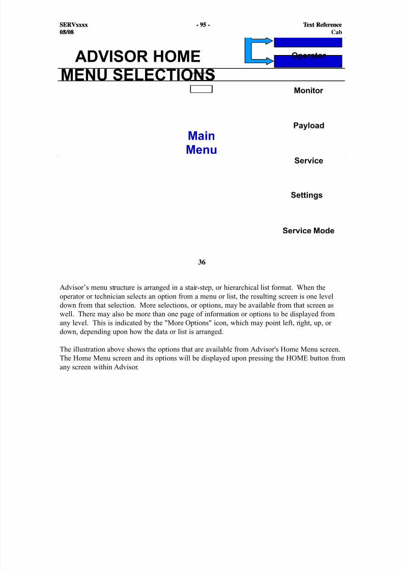
8/9/2019 797F HAA - Meeting Guide.pdf
http://slidepdf.com/reader/full/797f-haa-meeting-guidepdf 95/367
#
SERVxxxx - 95 - Text Reference08/08
36
Advisor’s menu structure is arranged in a stair-step, or hierarchical list format. When theoperator or technician selects an option from a menu or list, the resulting screen is one leveldown from that selection. More selections, or options, may be available from that screen aswell. There may also be more than one page of information or options to be displayed fromany level. This is indicated by the "More Options" icon, which may point left, right, up, ordown, depending upon how the data or list is arranged.
The illustration above shows the options that are available from Advisor's Home Menu screen.The Home Menu screen and its options will be displayed upon pressing the HOME button fromany screen within Advisor.
SERVxxxx - 95 - Text Reference03/08 Cab
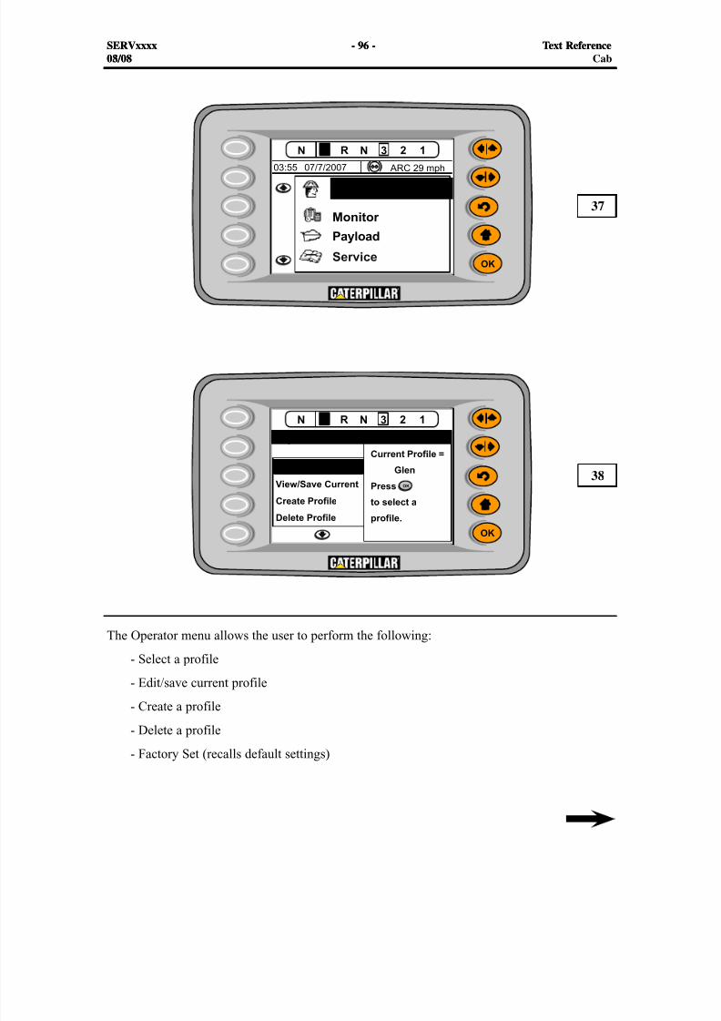
8/9/2019 797F HAA - Meeting Guide.pdf
http://slidepdf.com/reader/full/797f-haa-meeting-guidepdf 96/367
#
#
SERVxxxx - 96 - Text Reference08/08
The Operator menu allows the user to perform the following:
- Select a profile
- Edit/save current profile
- Create a profile
- Delete a profile
- Factory Set (recalls default settings)
37
38
SERVxxxx - 96 - Text Reference03/08 Cab

8/9/2019 797F HAA - Meeting Guide.pdf
http://slidepdf.com/reader/full/797f-haa-meeting-guidepdf 97/367
SERVxxxx - 97 - Text Reference08/08
The profile of an operator is a saved set of preferences that is identified by a name. Once the profile is created, the operator may associate various display settings and settings for the powertrain to that profile. After all of the parameters have been adjusted to the operator's preference,the operator may then save the parameters for future use.
NOTE: If the Advisor panel display receives a power disconnect before 6 minutes ofsaving the profile, the profile will not be saved. However, if the Advisor panel displayreceives a key switch cycle the profile will be saved.
SERVxxxx - 97 - Text Reference03/08 Cab
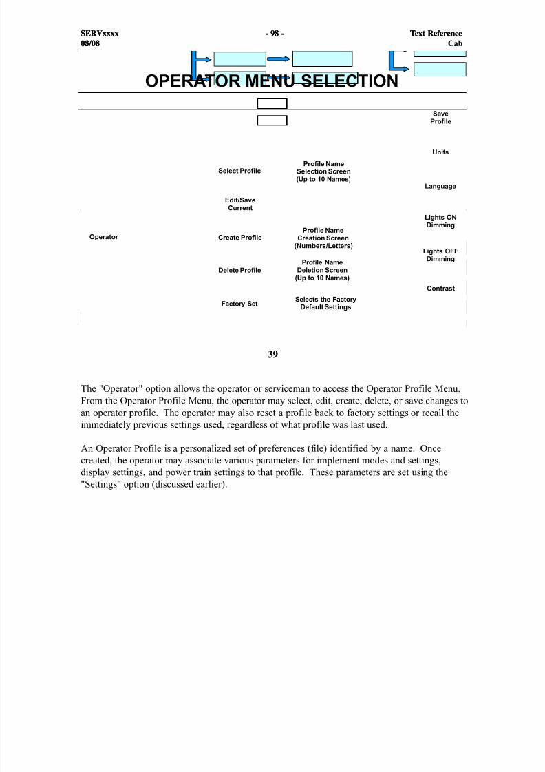
8/9/2019 797F HAA - Meeting Guide.pdf
http://slidepdf.com/reader/full/797f-haa-meeting-guidepdf 98/367
#
SERVxxxx - 98 - Text Reference08/08
39
The "Operator" option allows the operator or serviceman to access the Operator Profile Menu.From the Operator Profile Menu, the operator may select, edit, create, delete, or save changes toan operator profile. The operator may also reset a profile back to factory settings or recall theimmediately previous settings used, regardless of what profile was last used.
An Operator Profile is a personalized set of preferences (file) identified by a name. Oncecreated, the operator may associate various parameters for implement modes and settings,display settings, and power train settings to that profile. These parameters are set using the"Settings" option (discussed earlier).
SERVxxxx - 98 - Text Reference03/08 Cab
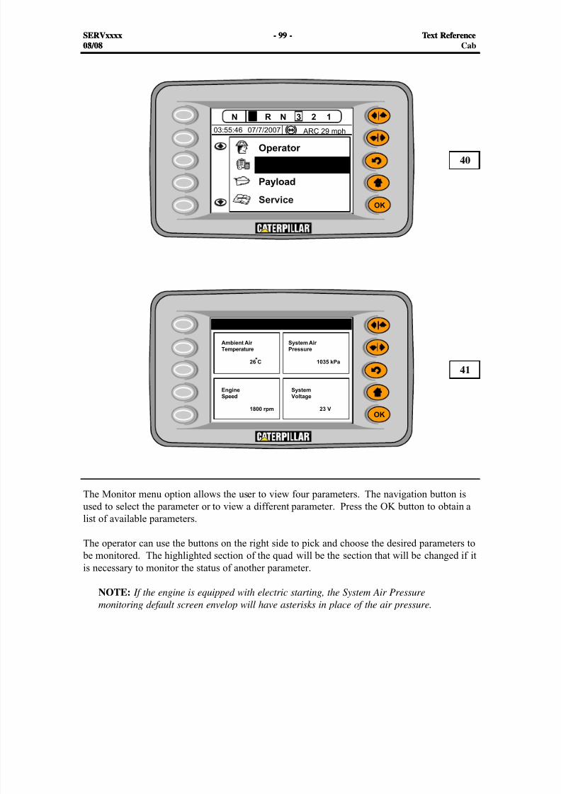
8/9/2019 797F HAA - Meeting Guide.pdf
http://slidepdf.com/reader/full/797f-haa-meeting-guidepdf 99/367
#
#
SERVxxxx - 99 - Text Reference08/08
The Monitor menu option allows the user to view four parameters. The navigation button isused to select the parameter or to view a different parameter. Press the OK button to obtain a
list of available parameters.
The operator can use the buttons on the right side to pick and choose the desired parameters to be monitored. The highlighted section of the quad will be the section that will be changed if itis necessary to monitor the status of another parameter.
NOTE: If the engine is equipped with electric starting, the System Air Pressuremonitoring default screen envelop will have asterisks in place of the air pressure.
40
41
SERVxxxx - 99 - Text Reference03/08 Cab
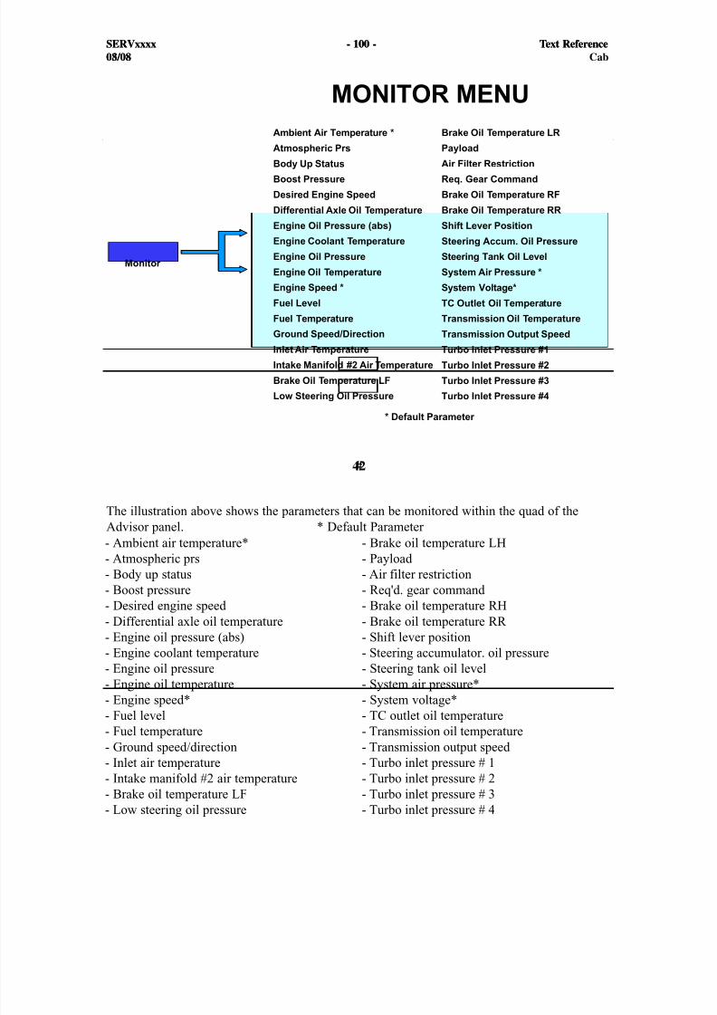
8/9/2019 797F HAA - Meeting Guide.pdf
http://slidepdf.com/reader/full/797f-haa-meeting-guidepdf 100/367
#
SERVxxxx - 100 - Text Reference08/08
42
The illustration above shows the parameters that can be monitored within the quad of theAdvisor panel. * Default Parameter
SERVxxxx - 100 - Text Reference03/08 Cab
- Ambient air temperature*- Atmospheric prs- Body up status- Boost pressure- Desired engine speed - Differential axle oil temperature- Engine oil pressure (abs)- Engine coolant temperature- Engine oil pressure- Engine oil temperature- Engine speed*- Fuel level- Fuel temperature- Ground speed/direction- Inlet air temperature- Intake manifold #2 air temperature- Brake oil temperature LF- Low steering oil pressure
- Brake oil temperature LH- Payload - Air filter restriction- Req'd. gear command - Brake oil temperature RH- Brake oil temperature RR - Shift lever position- Steering accumulator. oil pressure- Steering tank oil level- System air pressure*- System voltage*- TC outlet oil temperature- Transmission oil temperature- Transmission output speed - Turbo inlet pressure # 1- Turbo inlet pressure # 2- Turbo inlet pressure # 3- Turbo inlet pressure # 4
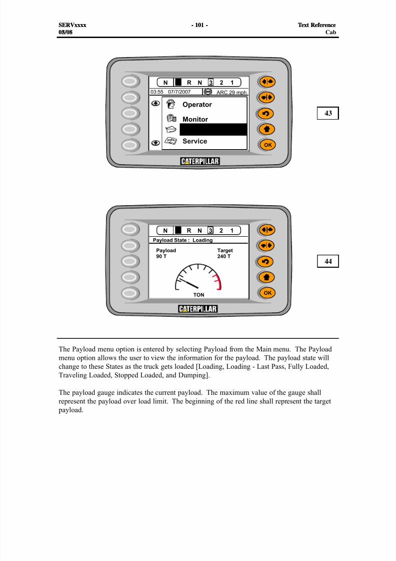
8/9/2019 797F HAA - Meeting Guide.pdf
http://slidepdf.com/reader/full/797f-haa-meeting-guidepdf 101/367
#
#
SERVxxxx - 101 - Text Reference08/08
The Payload menu option is entered by selecting Payload from the Main menu. The Payloadmenu option allows the user to view the information for the payload. The payload state will
change to these States as the truck gets loaded [Loading, Loading - Last Pass, Fully Loaded,Traveling Loaded, Stopped Loaded, and Dumping].
The payload gauge indicates the current payload. The maximum value of the gauge shallrepresent the payload over load limit. The beginning of the red line shall represent the target
payload.
43
44
SERVxxxx - 101 - Text Reference03/08 Cab
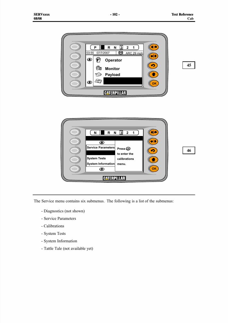
8/9/2019 797F HAA - Meeting Guide.pdf
http://slidepdf.com/reader/full/797f-haa-meeting-guidepdf 102/367
#
#
SERVxxxx - 102 - Text Reference08/08
The Service menu contains six submenus. The following is a list of the submenus:
- Diagnostics (not shown)- Service Parameters
- Calibrations
- System Tests
- System Information
- Tattle Tale (not available yet)
45
46
SERVxxxx - 102 - Text Reference03/08 Cab
8/9/2019 797F HAA - Meeting Guide.pdf
http://slidepdf.com/reader/full/797f-haa-meeting-guidepdf 103/367
SERVxxxx - 103 - Text Reference08/08
The Trigger Snapshot menu option allows the user to manually initiate a snapshot of the systemin addition to the snapshots that are already programmed. The snapshot will remain active untilthe time has elapsed.
The Data Logger Start menu option allows the user to initiate the data logger. If theinformation for the data logger is being downloaded from the machine, the data logger cannot
be started. The operator can initiate and stop the data logger numerous times until the total ofthirty minutes of data logging has elapsed.
The Data Logger Reset menu option allows the user to reset the data logger, which clears all ofthe logged information. Thirty minutes will be available after the data logger has been reset.
NOTE: The Data Logger is the only onboard file that can be reset through the Advisordisplay. The Advisor must be either in the Service Mode or Cat ET must be connectedto the data link to reset the data logger.
SERVxxxx - 103 - Text Reference03/08 Cab
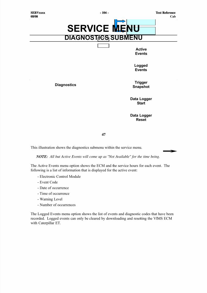
8/9/2019 797F HAA - Meeting Guide.pdf
http://slidepdf.com/reader/full/797f-haa-meeting-guidepdf 104/367
#
SERVxxxx - 104 - Text Reference08/08
47
This illustration shows the diagnostics submenu within the service menu.
NOTE: All but Active Events will come up as "Not Available" for the time being.
The Active Events menu option shows the ECM and the service hours for each event. Thefollowing is a list of information that is displayed for the active event:
- Electronic Control Module
- Event Code
- Date of occurrence
- Time of occurrence- Warning Level
- Number of occurrences
The Logged Events menu option shows the list of events and diagnostic codes that have beenrecorded. Logged events can only be cleared by downloading and resetting the VIMS ECMwith Caterpillar ET.
SERVxxxx - 104 - Text Reference03/08 Cab

8/9/2019 797F HAA - Meeting Guide.pdf
http://slidepdf.com/reader/full/797f-haa-meeting-guidepdf 105/367
1
SERVxxxx - 105 - Text Reference08/08SERVxxxx - 105 - Text Reference03/08 Cab
48
The Screen Shot above shows the top level menu of the Service: Diagnostics menu
The menu items available from this screen are
- Active Events
- Logged Events- Trigger Snapshots
- Data Logger Start/Stop
- Data Logger Reset
Active Events
Use the Up/Down arrow buttons on Advisor to highlight "Active Events."
Press the OK button to view a list of all the Events that are currently active on the truck.
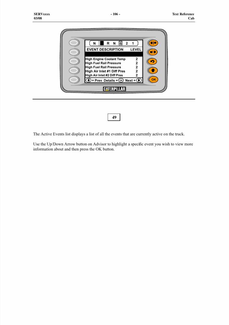
8/9/2019 797F HAA - Meeting Guide.pdf
http://slidepdf.com/reader/full/797f-haa-meeting-guidepdf 106/367
SERVxxxx - 106 - Text Reference03/08 Cab
49
The Active Events list displays a list of all the events that are currently active on the truck.
Use the Up/Down Arrow button on Advisor to highlight a speci c event you wish to view moreinformation about and then press the OK button.
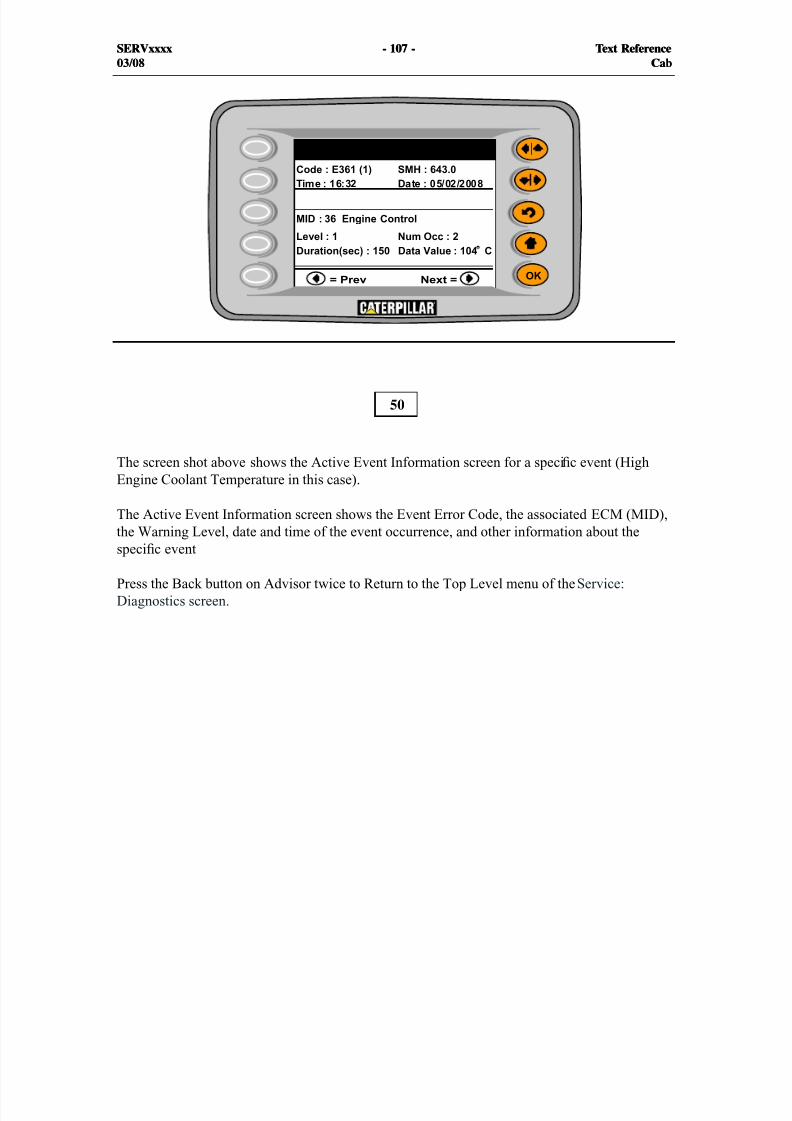
8/9/2019 797F HAA - Meeting Guide.pdf
http://slidepdf.com/reader/full/797f-haa-meeting-guidepdf 107/367
SERVxxxx - 107 - Text Reference03/08 Cab
SERVxxxx - 107 - Text Reference03/08 Cab
The screen shot above shows the Active Event Information screen for a speci c event (HighEngine Coolant Temperature in this case).
The Active Event Information screen shows the Event Error Code, the associated ECM (MID),the Warning Level, date and time of the event occurrence, and other information about the
speci c event
Press the Back button on Advisor twice to Return to the Top Level menu of the Service:Diagnostics screen.
50
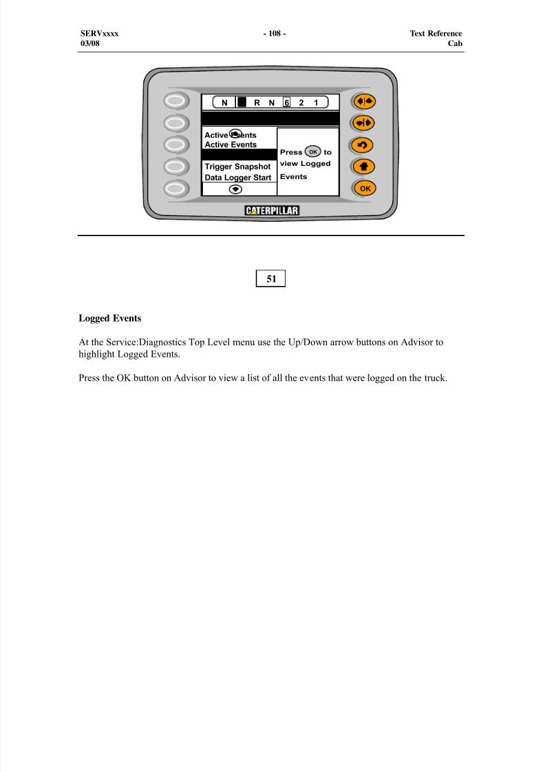
8/9/2019 797F HAA - Meeting Guide.pdf
http://slidepdf.com/reader/full/797f-haa-meeting-guidepdf 108/367
SERVxxxx - 108 - Text Reference03/08 Cab
51
Logged Events
At the Service:Diagnostics Top Level menu use the Up/Down arrow buttons on Advisor tohighlight Logged Events.
Press the OK button on Advisor to view a list of all the events that were logged on the truck.
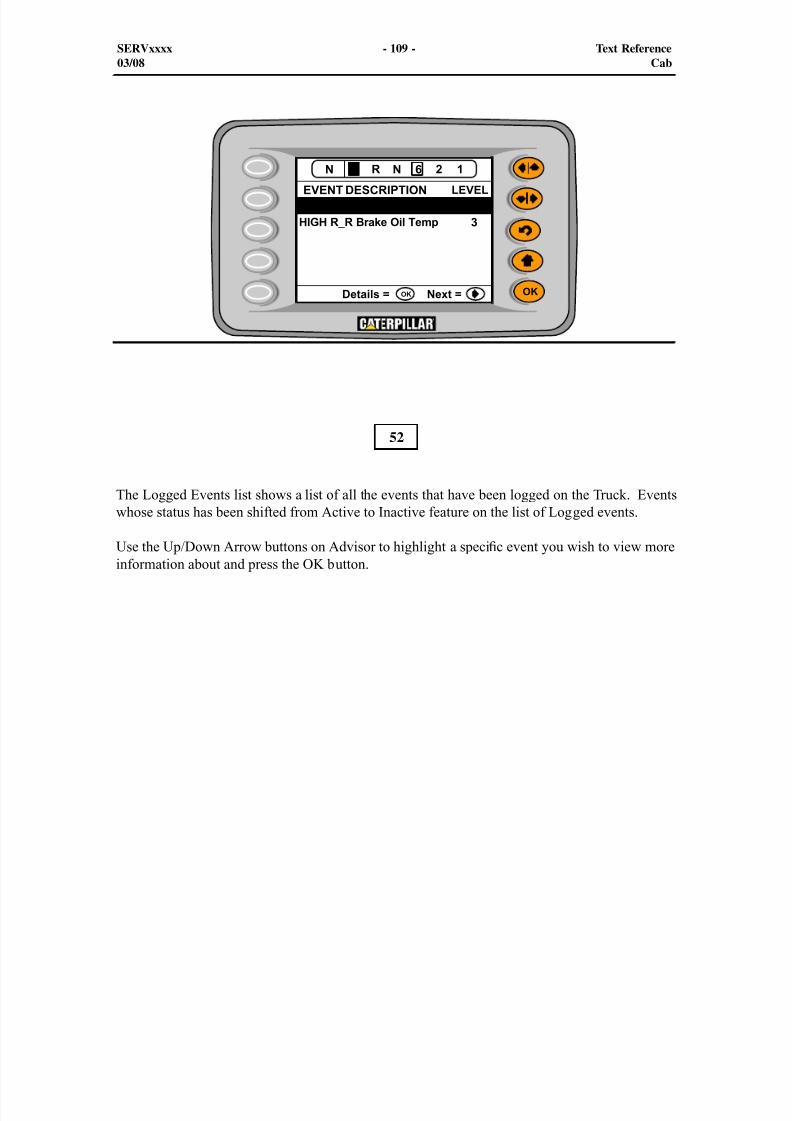
8/9/2019 797F HAA - Meeting Guide.pdf
http://slidepdf.com/reader/full/797f-haa-meeting-guidepdf 109/367
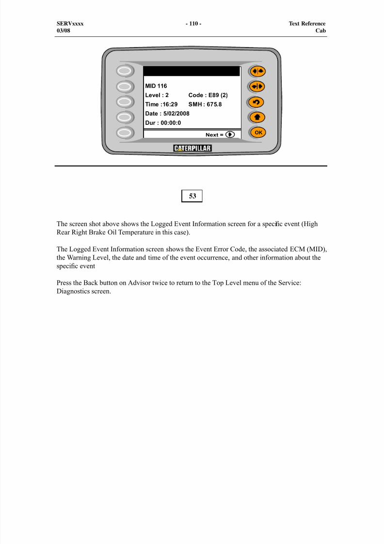
8/9/2019 797F HAA - Meeting Guide.pdf
http://slidepdf.com/reader/full/797f-haa-meeting-guidepdf 110/367
SERVxxxx - 110 - Text Reference03/08 Cab
The screen shot above shows the Logged Event Information screen for a speci c event (HighRear Right Brake Oil Temperature in this case).
The Logged Event Information screen shows the Event Error Code, the associated ECM (MID),the Warning Level, the date and time of the event occurrence, and other information about the
speci c event
Press the Back button on Advisor twice to return to the Top Level menu of the Service:Diagnostics screen.
53
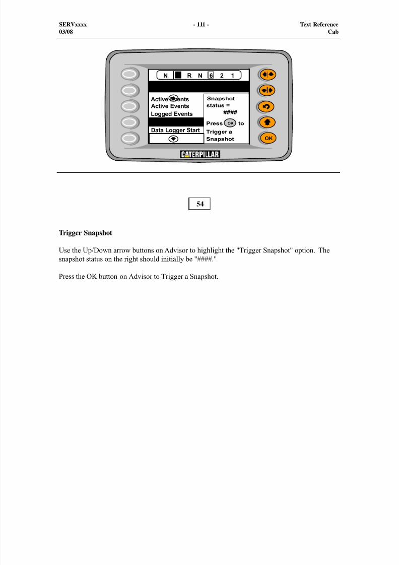
8/9/2019 797F HAA - Meeting Guide.pdf
http://slidepdf.com/reader/full/797f-haa-meeting-guidepdf 111/367
SERVxxxx - 111 - Text Reference03/08 Cab
54
Trigger Snapshot
Use the Up/Down arrow buttons on Advisor to highlight the "Trigger Snapshot" option. Thesnapshot status on the right should initially be "####."
Press the OK button on Advisor to Trigger a Snapshot.
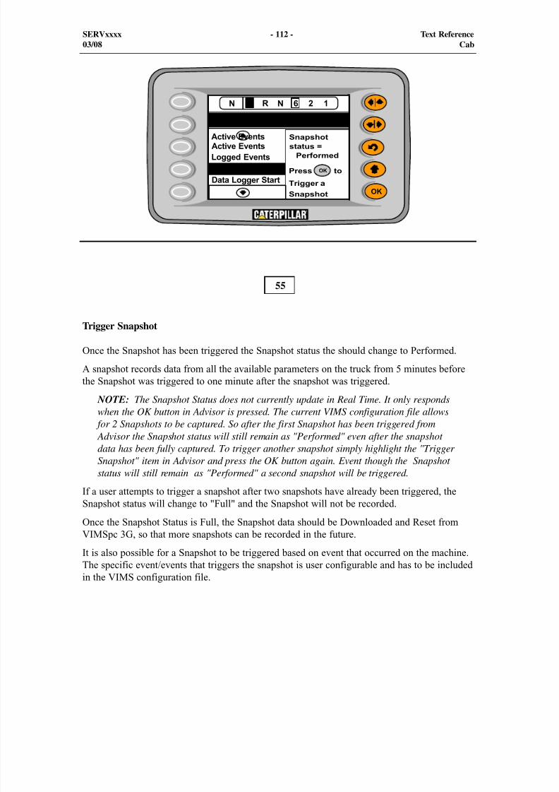
8/9/2019 797F HAA - Meeting Guide.pdf
http://slidepdf.com/reader/full/797f-haa-meeting-guidepdf 112/367
SERVxxxx - 112 - Text Reference03/08 Cab
55
Trigger Snapshot
Once the Snapshot has been triggered the Snapshot status the should change to Performed.
A snapshot records data from all the available parameters on the truck from 5 minutes beforethe Snapshot was triggered to one minute after the snapshot was triggered.
NOTE: The Snapshot Status does not currently update in Real Time. It only respondswhen the OK button in Advisor is pressed. The current VIMS configuration file allows
for 2 Snapshots to be captured. So after the first Snapshot has been triggered from Advisor the Snapshot status will still remain as "Performed" even after the snapshotdata has been fully captured. To trigger another snapshot simply highlight the "TriggerSnapshot" item in Advisor and press the OK button again. Event though the Snapshotstatus will still remain as "Performed" a second snapshot will be triggered.
If a user attempts to trigger a snapshot after two snapshots have already been triggered, theSnapshot status will change to "Full" and the Snapshot will not be recorded.
Once the Snapshot Status is Full, the Snapshot data should be Downloaded and Reset fromVIMSpc 3G, so that more snapshots can be recorded in the future.
It is also possible for a Snapshot to be triggered based on event that occurred on the machine.The specific event/events that triggers the snapshot is user configurable and has to be includedin the VIMS configuration file.
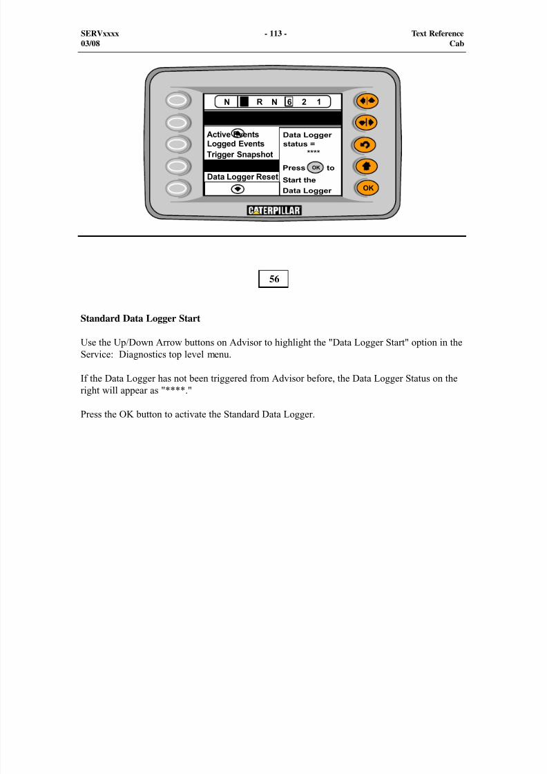
8/9/2019 797F HAA - Meeting Guide.pdf
http://slidepdf.com/reader/full/797f-haa-meeting-guidepdf 113/367
SERVxxxx - 113 - Text Reference03/08 Cab
56
Standard Data Logger Start
Use the Up/Down Arrow buttons on Advisor to highlight the "Data Logger Start" option in theService: Diagnostics top level menu.
If the Data Logger has not been triggered from Advisor before, the Data Logger Status on theright will appear as "****."
Press the OK button to activate the Standard Data Logger.
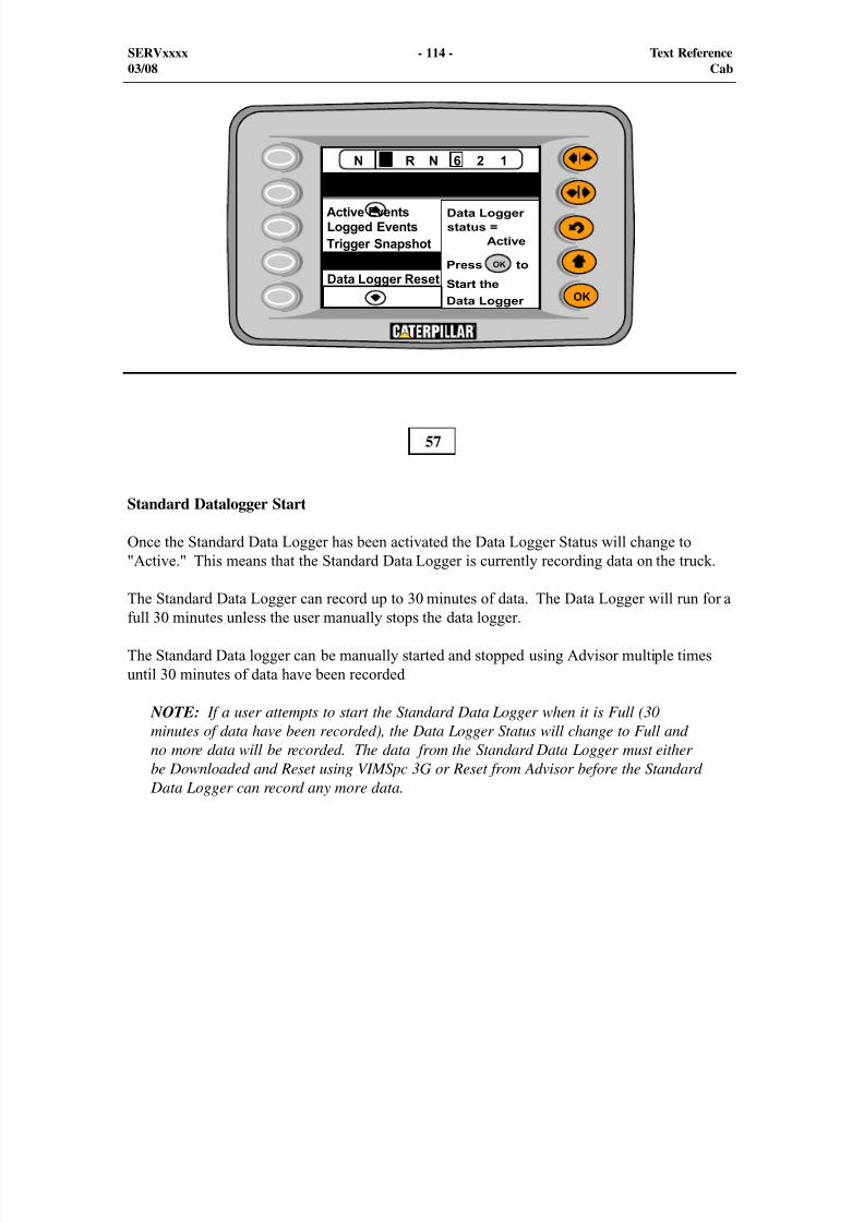
8/9/2019 797F HAA - Meeting Guide.pdf
http://slidepdf.com/reader/full/797f-haa-meeting-guidepdf 114/367
SERVxxxx - 114 - Text Reference03/08 Cab
57
Standard Datalogger Start
Once the Standard Data Logger has been activated the Data Logger Status will change to"Active." This means that the Standard Data Logger is currently recording data on the truck.
The Standard Data Logger can record up to 30 minutes of data. The Data Logger will run for afull 30 minutes unless the user manually stops the data logger.
The Standard Data logger can be manually started and stopped using Advisor multiple timesuntil 30 minutes of data have been recorded
NOTE: If a user attempts to start the Standard Data Logger when it is Full (30minutes of data have been recorded), the Data Logger Status will change to Full andno more data will be recorded. The data from the Standard Data Logger must eitherbe Downloaded and Reset using VIMSpc 3G or Reset from Advisor before the Standard
Data Logger can record any more data.

8/9/2019 797F HAA - Meeting Guide.pdf
http://slidepdf.com/reader/full/797f-haa-meeting-guidepdf 115/367
SERVxxxx - 115 - Text Reference03/08 Cab
58
Standard Data Logger Stop
The Standard Data Logger can be manually stopped using Advisor by using the DataloggerStop option.
When the Standard Data Logger has been activated the screen on Advisor will match that of thescreen shot on the previous page. In order to Stop the Standard Data Logger first press the Uparrow button on Advisor to Scroll away from the "Data Logger Start option." If the StandardData Logger is currently active, the "Data Logger Stop" option should appear in its place.
Use the Down arrow button Advisor to highlight the Data Logger Stop option. The Advisorscreen should now match the screen shot above. Press the OK button to Stop the StandardDataLogger.

8/9/2019 797F HAA - Meeting Guide.pdf
http://slidepdf.com/reader/full/797f-haa-meeting-guidepdf 116/367
SERVxxxx - 116 - Text Reference03/08 Cab
59
Standard Data Logger Stop
Once the Standard Data Logger has been manually stopped, the Data Logger Status shouldchange to "Inactive" and the advisor screen should match the screen shot above.
If 30 minutes of data have not been recorded as yet, the user may manually activate the standarddata logger again at any time he/she chooses. This can be accomplished by rst pressing the Uparrow button on Advisor to scroll away from the "Data Logger Stop" option. If the Data Loggerhas actually been stopped then the "Data Logger Start" option should appear in its place. Theuser may now use the Down arrow button on Advisor to scroll back to the "Data Logger Start"option and activate it if he/she wishers.
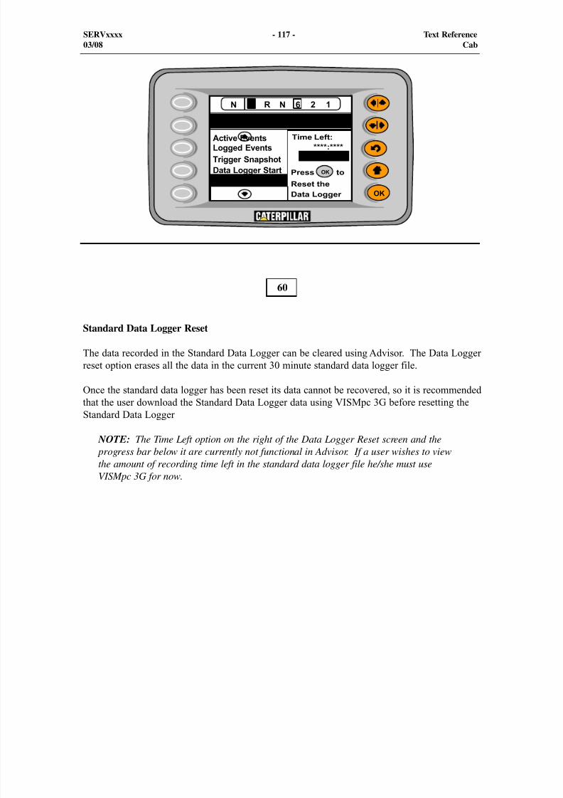
8/9/2019 797F HAA - Meeting Guide.pdf
http://slidepdf.com/reader/full/797f-haa-meeting-guidepdf 117/367
SERVxxxx - 117 - Text Reference03/08 Cab
60
Standard Data Logger Reset
The data recorded in the Standard Data Logger can be cleared using Advisor. The Data Loggerreset option erases all the data in the current 30 minute standard data logger file.
Once the standard data logger has been reset its data cannot be recovered, so it is recommendedthat the user download the Standard Data Logger data using VISMpc 3G before resetting theStandard Data Logger
NOTE: The Time Left option on the right of the Data Logger Reset screen and the progress bar below it are currently not functional in Advisor. If a user wishes to viewthe amount of recording time left in the standard data logger file he/she must useVISMpc 3G for now.

8/9/2019 797F HAA - Meeting Guide.pdf
http://slidepdf.com/reader/full/797f-haa-meeting-guidepdf 118/367
#
SERV7106-xx - 118 - NPIVol. 12, No. X, 2006
61
SERVxxxx - 118 - Text Reference03/08 Cab
These illustrations show four of the five submenus within the service menu. The Diagnosticsubmenu is shown in the previous two visuals.
This illustration shows the Service Parameters submenu within the service menu.
The following Service Parameters options will be displayed:
- Sort By ECM
- Sort By Type
- All parameters
The Sort By ECM menu option allows the user to view the parameters that are associated witheach ECM. All of the parameters for the specific ECM are listed. The following ECMs can beselected:
- Advisor
- Engine
- Chassis
- Brake
- Transmission
- VIMS
8/9/2019 797F HAA - Meeting Guide.pdf
http://slidepdf.com/reader/full/797f-haa-meeting-guidepdf 119/367
SERVxxxx - 119 - Text Reference08/08
The Sort By Type menu option allows the user to view the parameters that are associated withdifferent components. The following types of parameters can be chosen:
- Temperatures
- Pressures
- Speeds
- Machine Status
- Operator Inputs
- Totals
The All Parameters menu option allows the user to view the entire list of parameters.
The Calibration submode option consists of the Truck Payload calibration.
The instrument cluster will initiate a self-test when the key start switch is moved to the START position. The gauge needles will move to the maximum right position for 0.5 seconds and thenreturn to the minimum left position. This action prevents the gauge needles from circling to the
bottom side of the gauge if the display is inverted.
The System Information menu option allows the user to view the information for the followingmachine ECMs:
- Advisor
- Engine
- Chassis
- Transmission
- Brake
- VIMS Main
- VIMS Application
SERVxxxx - 119 - Text Reference03/08 Cab
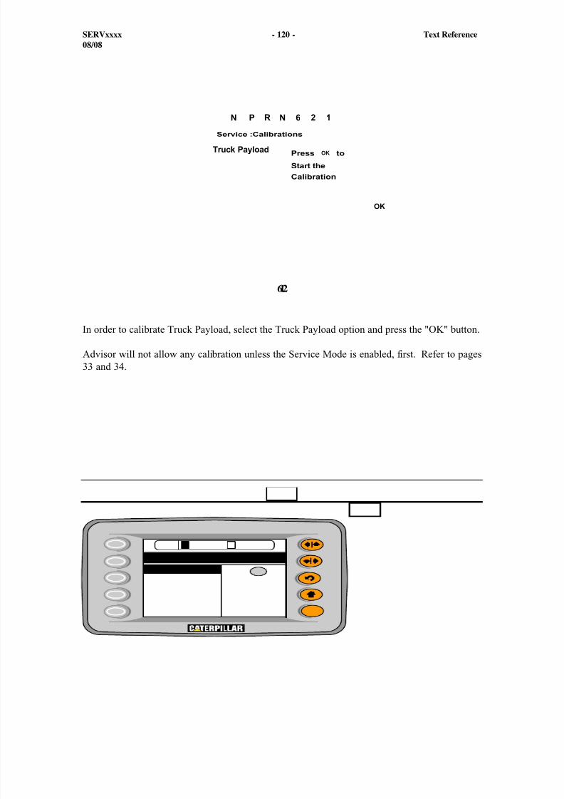
8/9/2019 797F HAA - Meeting Guide.pdf
http://slidepdf.com/reader/full/797f-haa-meeting-guidepdf 120/367
1
SERVxxxx - 120 - Text Reference08/08
62
In order to calibrate Truck Payload, select the Truck Payload option and press the "OK" button.
Advisor will not allow any calibration unless the Service Mode is enabled, first. Refer to pages33 and 34.
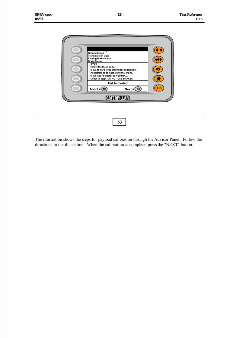
8/9/2019 797F HAA - Meeting Guide.pdf
http://slidepdf.com/reader/full/797f-haa-meeting-guidepdf 121/367
1
SERVxxxx - 121 - Text Reference08/08
The illustration shows the steps for payload calibration through the Advisor Panel. Follow thedirections in the illustration. When the calibration is complete, press the "NEXT" button.
63
SERVxxxx - 121 - Text Reference03/08 Cab
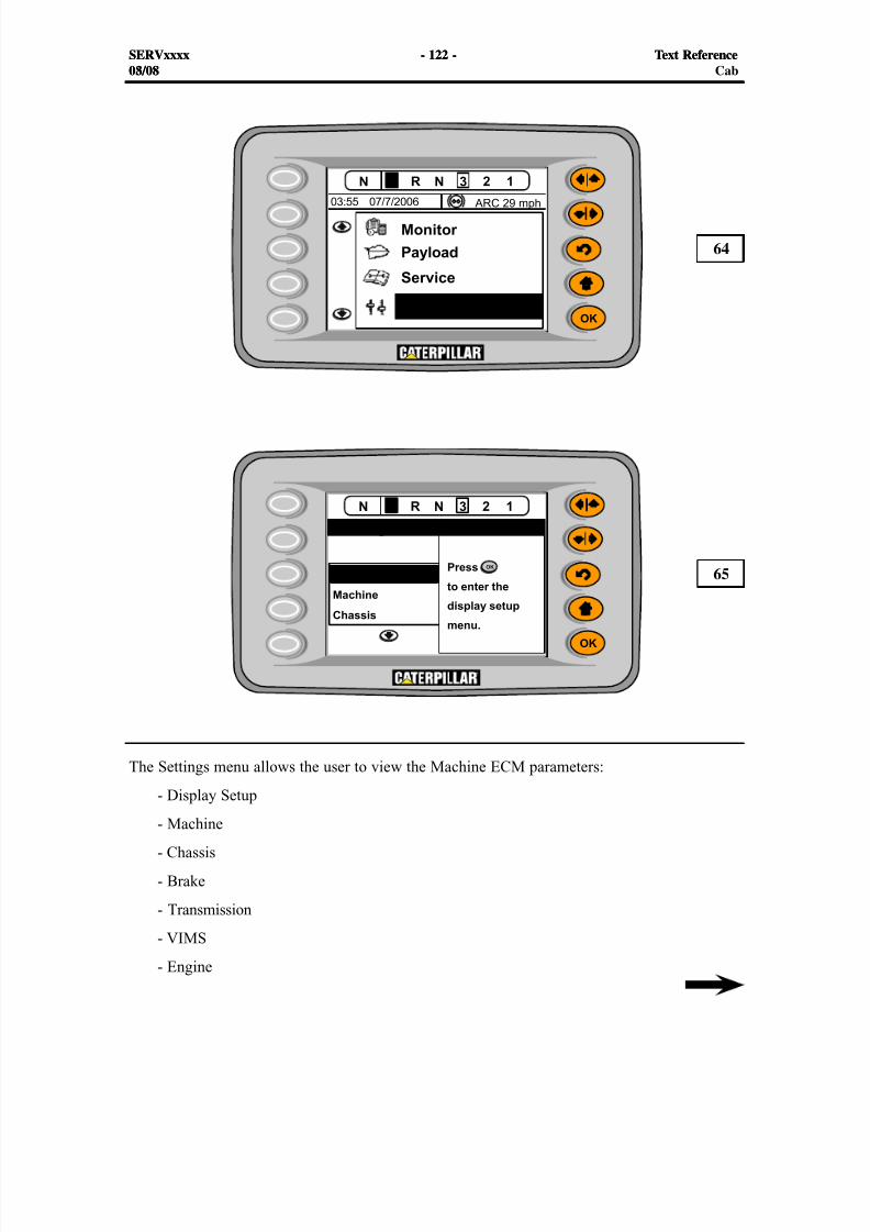
8/9/2019 797F HAA - Meeting Guide.pdf
http://slidepdf.com/reader/full/797f-haa-meeting-guidepdf 122/367
#
#
SERVxxxx - 122 - Text Reference08/08
The Settings menu allows the user to view the Machine ECM parameters:
- Display Setup
- Machine
- Chassis
- Brake
- Transmission
- VIMS
- Engine
64
65
SERVxxxx - 122 - Text Reference03/08 Cab
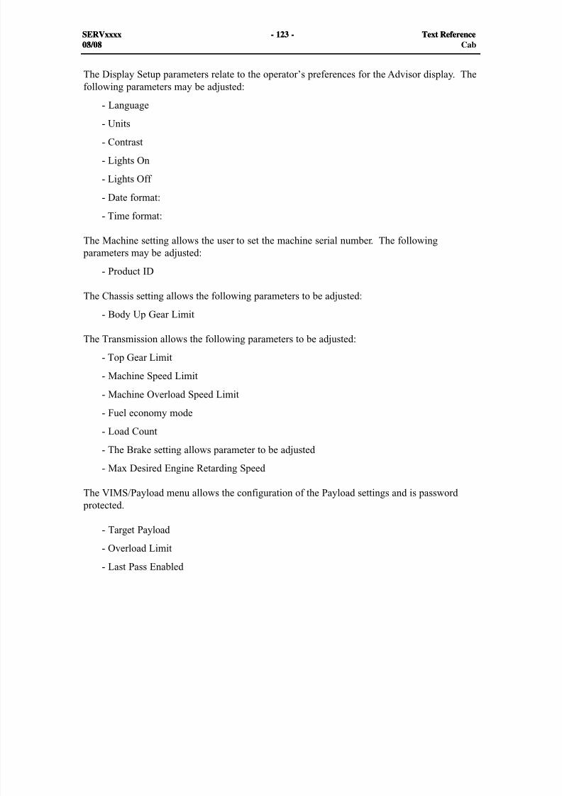
8/9/2019 797F HAA - Meeting Guide.pdf
http://slidepdf.com/reader/full/797f-haa-meeting-guidepdf 123/367
SERVxxxx - 123 - Text Reference08/08
The Display Setup parameters relate to the operator’s preferences for the Advisor display. Thefollowing parameters may be adjusted:
- Language
- Units
- Contrast
- Lights On
- Lights Off
- Date format:
- Time format:
The Machine setting allows the user to set the machine serial number. The following parameters may be adjusted:
- Product ID
The Chassis setting allows the following parameters to be adjusted:
- Body Up Gear Limit
The Transmission allows the following parameters to be adjusted:
- Top Gear Limit
- Machine Speed Limit
- Machine Overload Speed Limit
- Fuel economy mode
- Load Count
- The Brake setting allows parameter to be adjusted
- Max Desired Engine Retarding Speed
The VIMS/Payload menu allows the configuration of the Payload settings and is password protected.
- Target Payload
- Overload Limit
- Last Pass Enabled
SERVxxxx - 123 - Text Reference03/08 Cab
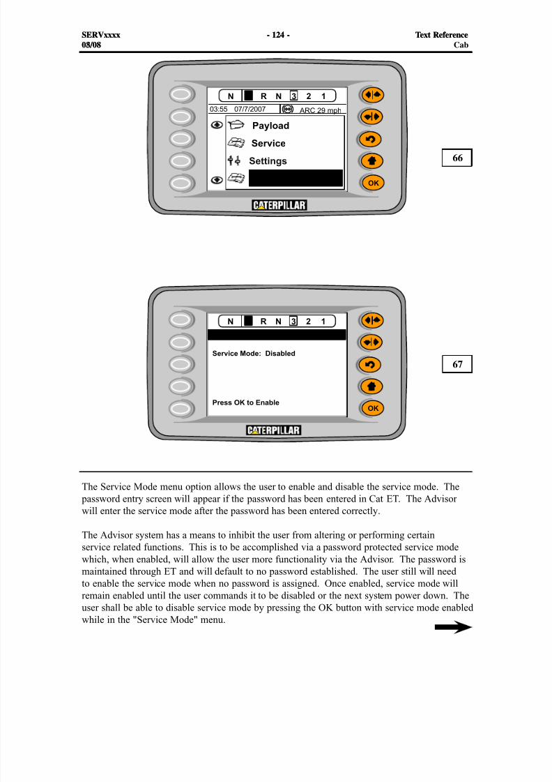
8/9/2019 797F HAA - Meeting Guide.pdf
http://slidepdf.com/reader/full/797f-haa-meeting-guidepdf 124/367
#
#
SERVxxxx - 124 - Text Reference08/08
The Service Mode menu option allows the user to enable and disable the service mode. The password entry screen will appear if the password has been entered in Cat ET. The Advisor
will enter the service mode after the password has been entered correctly.
The Advisor system has a means to inhibit the user from altering or performing certainservice related functions. This is to be accomplished via a password protected service modewhich, when enabled, will allow the user more functionality via the Advisor. The password ismaintained through ET and will default to no password established. The user still will needto enable the service mode when no password is assigned. Once enabled, service mode willremain enabled until the user commands it to be disabled or the next system power down. Theuser shall be able to disable service mode by pressing the OK button with service mode enabledwhile in the "Service Mode" menu.
66
67
SERVxxxx - 124 - Text Reference03/08 Cab
8/9/2019 797F HAA - Meeting Guide.pdf
http://slidepdf.com/reader/full/797f-haa-meeting-guidepdf 125/367
SERVxxxx - 125 - Text Reference08/08
The following list is a summary of the service mode functions that can be password protected:
- Product ID Change
- Equipment ID Change
- Top Gear Limit Change
- Body Up Gear Limit Change
- Machine Overload Speed Limit Change
- Machine Speed Limit Change
- Fuel Economy Mode Change (not supported at this time)
- Desired Engine Retarding Speed Change
- Target Payload Change (if payload is installed)
- Payload Overload Limit Change (if payload is installed)
- Last Pass Enabling (if payload is installed)
- Diagnostic\Event Clear Capability
- Payload Calibration
- Data Logger Reset
- Snapshot – Configure
- Tattle tale – Clear
SERVxxxx - 125 - Text Reference03/08 Cab
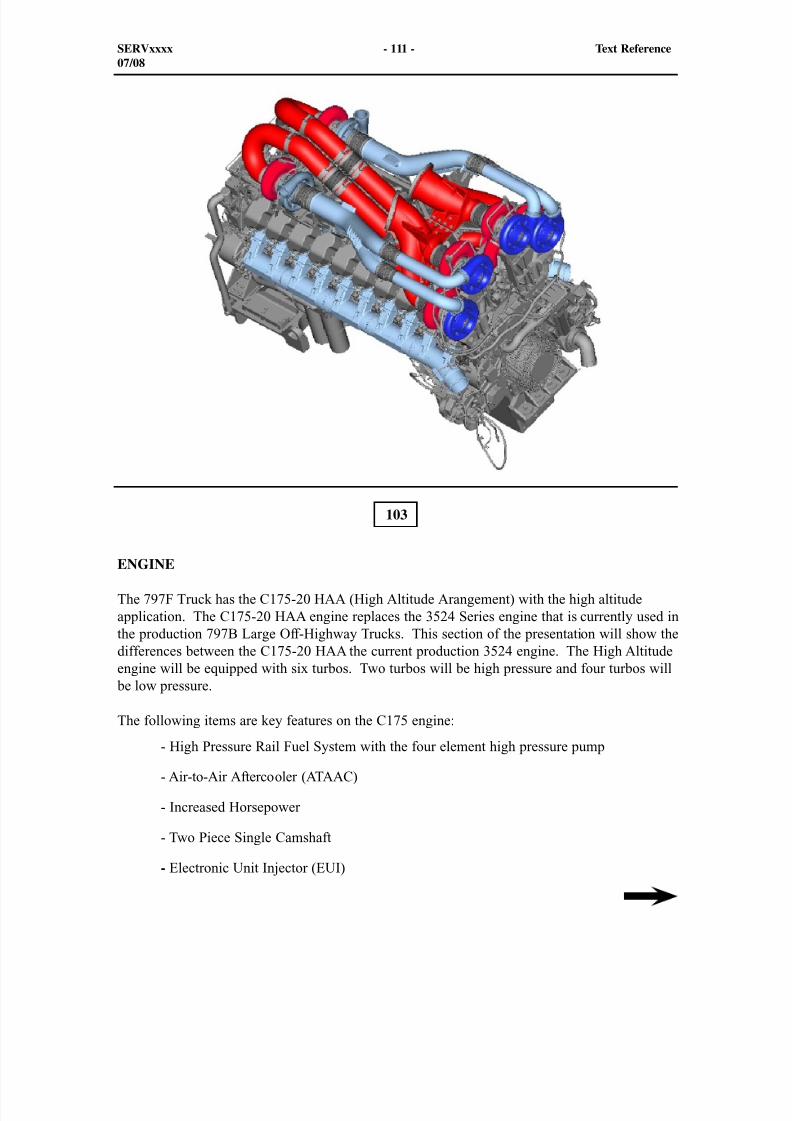
8/9/2019 797F HAA - Meeting Guide.pdf
http://slidepdf.com/reader/full/797f-haa-meeting-guidepdf 126/367
103
ENGINE
The 797F Truck has the C175-20 HAA (High Altitude Arangement) with the high altitudeapplication. The C175-20 HAA engine replaces the 3524 Series engine that is currently used inthe production 797B Large Off-Highway Trucks. This section of the presentation will show thedifferences between the C175-20 HAA the current production 3524 engine. The High Altitudeengine will be equipped with six turbos. Two turbos will be high pressure and four turbos will
be low pressure.
The following items are key features on the C175 engine:
- High Pressure Rail Fuel System with the four element high pressure pump
- Air-to-Air Aftercooler (ATAAC)
- Increased Horsepower
- Two Piece Single Camshaft
- Electronic Unit Injector (EUI)
SERVxxxx - 111 - Text Reference07/08
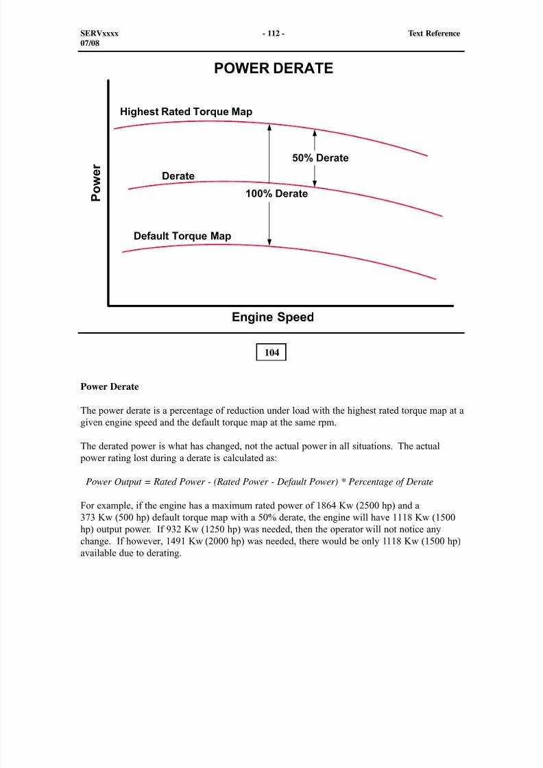
8/9/2019 797F HAA - Meeting Guide.pdf
http://slidepdf.com/reader/full/797f-haa-meeting-guidepdf 127/367
104
Power Derate
The power derate is a percentage of reduction under load with the highest rated torque map at agiven engine speed and the default torque map at the same rpm.
The derated power is what has changed, not the actual power in all situations. The actual power rating lost during a derate is calculated as:
Power Output = Rated Power - (Rated Power - Default Power) * Percentage of Derate
For example, if the engine has a maximum rated power of 1864 Kw (2500 hp) and a373 Kw (500 hp) default torque map with a 50% derate, the engine will have 1118 Kw (1500hp) output power. If 932 Kw (1250 hp) was needed, then the operator will not notice anychange. If however, 1491 Kw (2000 hp) was needed, there would be only 1118 Kw (1500 hp)available due to derating.
SERVxxxx - 112 - Text Reference07/08
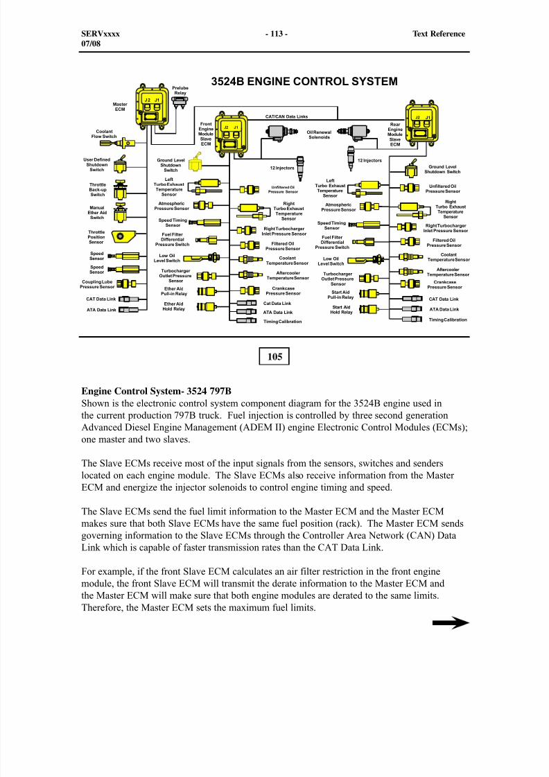
8/9/2019 797F HAA - Meeting Guide.pdf
http://slidepdf.com/reader/full/797f-haa-meeting-guidepdf 128/367

8/9/2019 797F HAA - Meeting Guide.pdf
http://slidepdf.com/reader/full/797f-haa-meeting-guidepdf 129/367
The Master ECM physically receives the input signals that must be sent to both enginemodules. Master ECM inputs are:
- Coolant flow
- User defined shutdowns
- Throttle back-up
- Manual ether injection (auto ether injection is controlled by the Slave ECMs)
- Throttle position
- Two engine speed timing sensors, one for each Slave Engine Control Module
SERVxxxx - 114 - Text Reference07/08
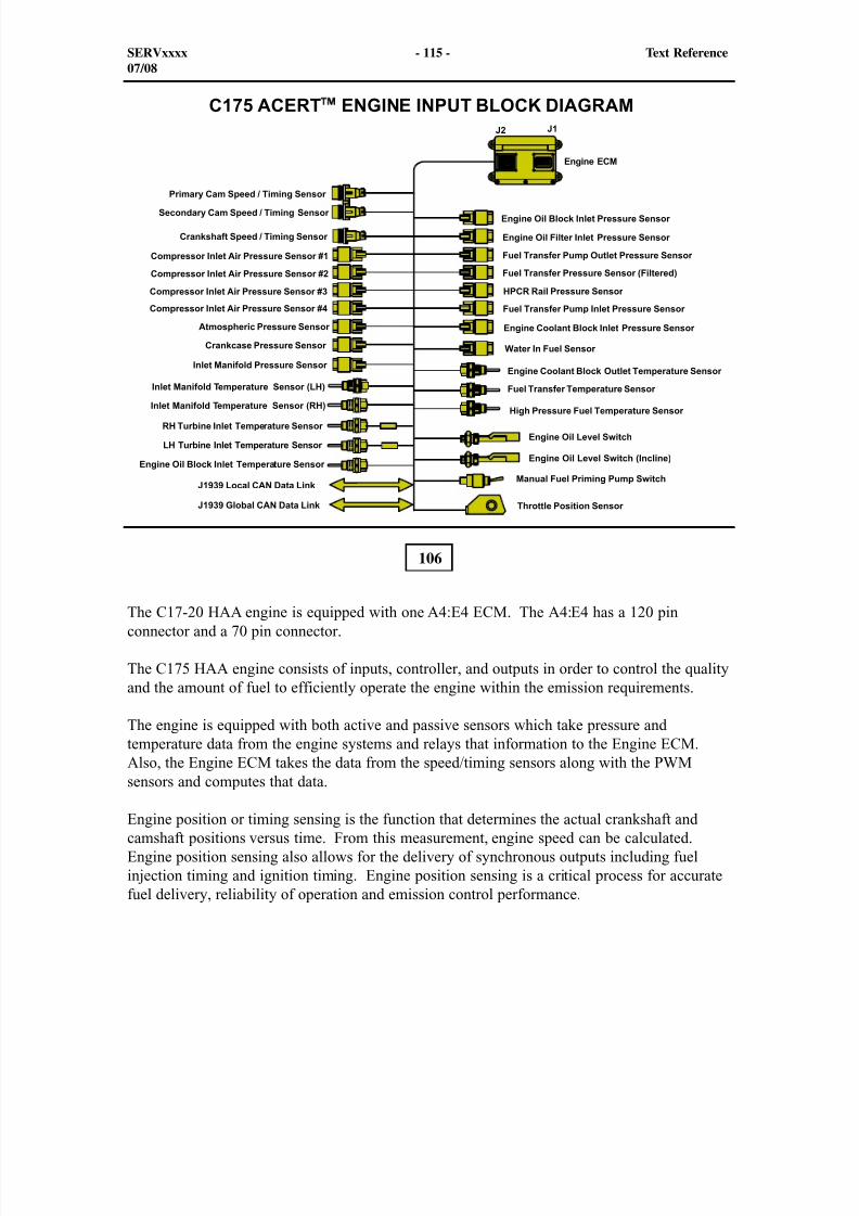
8/9/2019 797F HAA - Meeting Guide.pdf
http://slidepdf.com/reader/full/797f-haa-meeting-guidepdf 130/367
106
The C17-20 HAA engine is equipped with one A4:E4 ECM. The A4:E4 has a 120 pinconnector and a 70 pin connector.
The C175 HAA engine consists of inputs, controller, and outputs in order to control the qualityand the amount of fuel to efficiently operate the engine within the emission requirements.
The engine is equipped with both active and passive sensors which take pressure andtemperature data from the engine systems and relays that information to the Engine ECM.Also, the Engine ECM takes the data from the speed/timing sensors along with the PWMsensors and computes that data.
Engine position or timing sensing is the function that determines the actual crankshaft andcamshaft positions versus time. From this measurement, engine speed can be calculated.Engine position sensing also allows for the delivery of synchronous outputs including fuelinjection timing and ignition timing. Engine position sensing is a critical process for accuratefuel delivery, reliability of operation and emission control performance.
SERVxxxx - 115 - Text Reference07/08
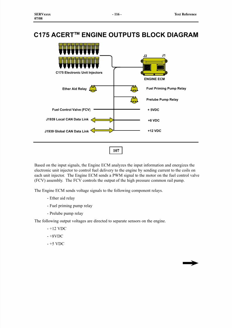
8/9/2019 797F HAA - Meeting Guide.pdf
http://slidepdf.com/reader/full/797f-haa-meeting-guidepdf 131/367
107
Based on the input signals, the Engine ECM analyzes the input information and energizes theelectronic unit injector to control fuel delivery to the engine by sending current to the coils oneach unit injector. The Engine ECM sends a PWM signal to the motor on the fuel control valve(FCV) assembly. The FCV controls the output of the high pressure common rail pump.
The Engine ECM sends voltage signals to the following component relays.
- Ether aid relay
- Fuel priming pump relay
- Prelube pump relayThe following output voltages are directed to separate sensors on the engine.
- +12 VDC
- +8VDC
- +5 VDC
SERVxxxx - 116 - Text Reference07/08

8/9/2019 797F HAA - Meeting Guide.pdf
http://slidepdf.com/reader/full/797f-haa-meeting-guidepdf 132/367
The Controller Area Network (CAN) Data Link can be recognized by the shielded cable and theconnectors that are also shielded. Inside is a twisted pair of copper wires. The CAN Data Linkis used for high speed transmission of data between the Engine ECM. CAN troubleshootingwill be explained later in this presentation.
Also, the Cat Data Link can be used as a troubleshooting tool. Connect a multimeter in usingspoons in parallel (DC voltage range) to the pin of the (-) wire and the (+) wire. Turn thekey switch to the ON position (do not start the engine). Check the voltage on the meter. Thevoltage should be between 0.8 and 2.8 volts. The voltage amplitude should vary but range
between these voltages. When the range of voltage stays between these tolerances, the CatData Link is communicating with the ECM.
SERVxxxx - 117 - Text Reference07/08
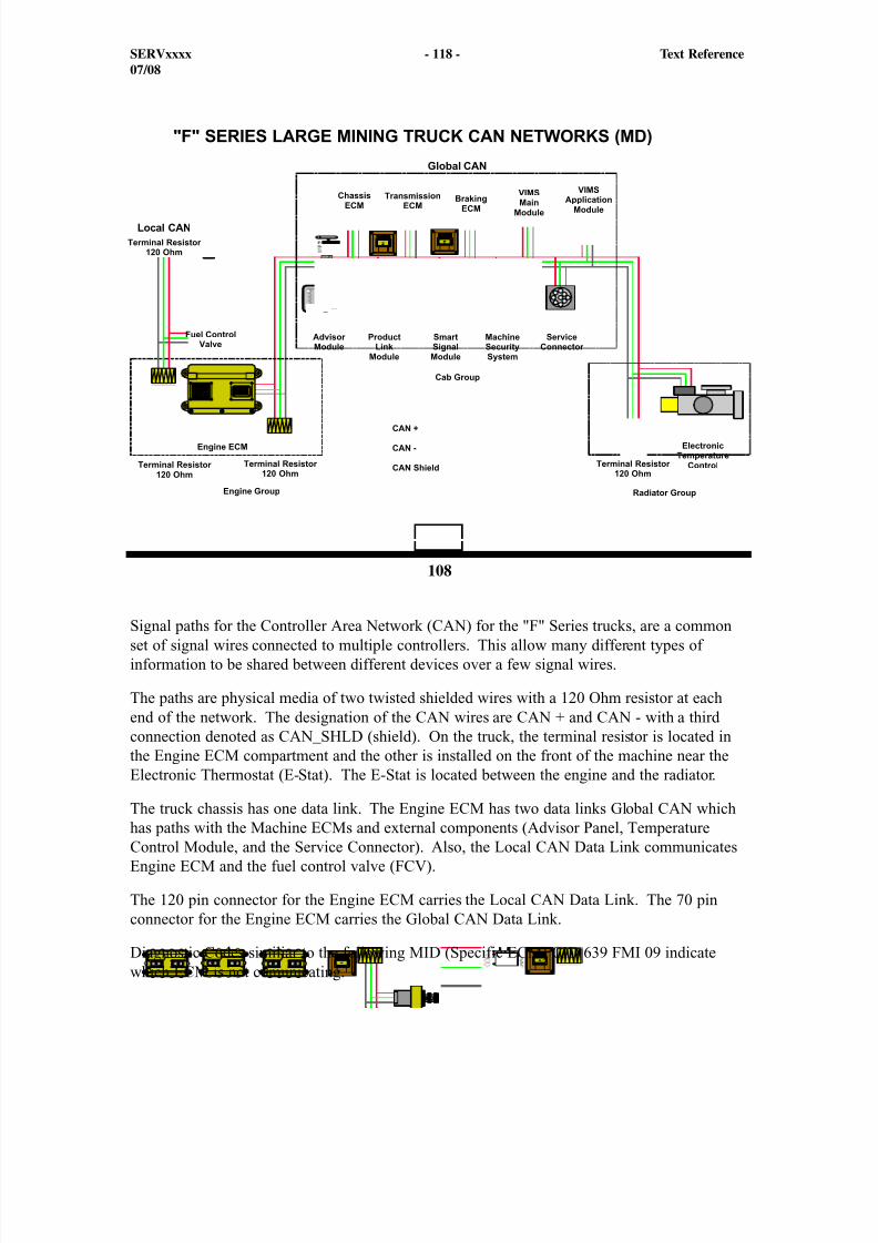
8/9/2019 797F HAA - Meeting Guide.pdf
http://slidepdf.com/reader/full/797f-haa-meeting-guidepdf 133/367
108
Signal paths for the Controller Area Network (CAN) for the "F" Series trucks, are a commonset of signal wires connected to multiple controllers. This allow many different types ofinformation to be shared between different devices over a few signal wires.
The paths are physical media of two twisted shielded wires with a 120 Ohm resistor at eachend of the network. The designation of the CAN wires are CAN + and CAN - with a thirdconnection denoted as CAN_SHLD (shield). On the truck, the terminal resistor is located inthe Engine ECM compartment and the other is installed on the front of the machine near theElectronic Thermostat (E-Stat). The E-Stat is located between the engine and the radiator.
The truck chassis has one data link. The Engine ECM has two data links Global CAN whichhas paths with the Machine ECMs and external components (Advisor Panel, TemperatureControl Module, and the Service Connector). Also, the Local CAN Data Link communicatesEngine ECM and the fuel control valve (FCV).
The 120 pin connector for the Engine ECM carries the Local CAN Data Link. The 70 pinconnector for the Engine ECM carries the Global CAN Data Link.
Diagnostic Codes similiar to the following MID (Specific ECM) CID 639 FMI 09 indicatewhich ECM is not comunicating.
SERVxxxx - 118 - Text Reference07/08
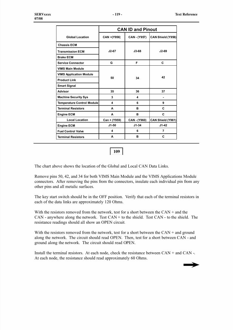
8/9/2019 797F HAA - Meeting Guide.pdf
http://slidepdf.com/reader/full/797f-haa-meeting-guidepdf 134/367
109
The chart above shows the location of the Global and Local CAN Data Links.
Remove pins 50, 42, and 34 for both VIMS Main Module and the VIMS Applications Moduleconnectors. After removing the pins from the connectors, insulate each individual pin from anyother pins and all metalic surfaces.
The key start switch should be in the OFF position. Verify that each of the terminal resistors ineach of the data links are approximately 120 Ohms.
With the resistors removed from the network, test for a short between the CAN + and theCAN - anywhere along the network. Test CAN + to the shield. Test CAN - to the shield. Theresistance readings should all show an OPEN circuit.
With the resistors removed from the network, test for a short between the CAN + and groundalong the network. The circuit should read OPEN. Then, test for a short between CAN - andground along the network. The circuit should read OPEN.
Install the terminal resistors. At each node, check the resistance between CAN + and CAN -.At each node, the resistance should read approximately 60 Ohms.
SERVxxxx - 119 - Text Reference07/08
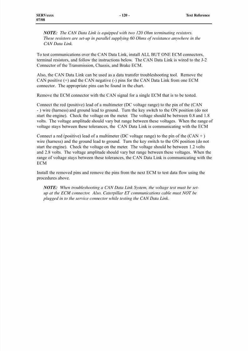
8/9/2019 797F HAA - Meeting Guide.pdf
http://slidepdf.com/reader/full/797f-haa-meeting-guidepdf 135/367
NOTE: The CAN Data Link is equipped with two 120 Ohm terminating resistors.These resistors are set-up in parallel supplying 60 Ohms of resistance anywhere in theCAN Data Link.
To test communications over the CAN Data Link, install ALL BUT ONE ECM connectors,terminal resistors, and follow the instructions below. The CAN Data Link is wired to the J-2Connector of the Transmission, Chassis, and Brake ECM.
Also, the CAN Data Link can be used as a data transfer troubleshooting tool. Remove theCAN positive (+) and the CAN negative (-) pins for the CAN Data Link from one ECMconnector. The appropriate pins can be found in the chart.
Remove the ECM connector with the CAN signal for a single ECM that is to be tested.
Connect the red (positive) lead of a multimeter (DC voltage range) to the pin of the (CAN- ) wire (harness) and ground lead to ground. Turn the key switch to the ON position (do not
start the engine). Check the voltage on the meter. The voltage should be between 0.8 and 1.8volts. The voltage amplitude should vary but range between these voltages. When the range ofvoltage stays between these tolerances, the CAN Data Link is communicating with the ECM
Connect a red (positive) lead of a multimeter (DC voltage range) to the pin of the (CAN + )wire (harness) and the ground lead to ground. Turn the key switch to the ON position (do notstart the engine). Check the voltage on the meter. The voltage should be between 1.2 voltsand 2.8 volts. The voltage amplitude should vary but range between these voltages. When therange of voltage stays between these tolerances, the CAN Data Link is communicating with theECM
Install the removed pins and remove the pins from the next ECM to test data flow using the procedures above.
NOTE: When troubleshooting a CAN Data Link System, the voltage test must be set-up at the ECM connector. Also, Caterpillar ET communications cable must NOT be
plugged in to the service connector while testing the CAN Data Link.
SERVxxxx - 120 - Text Reference07/08
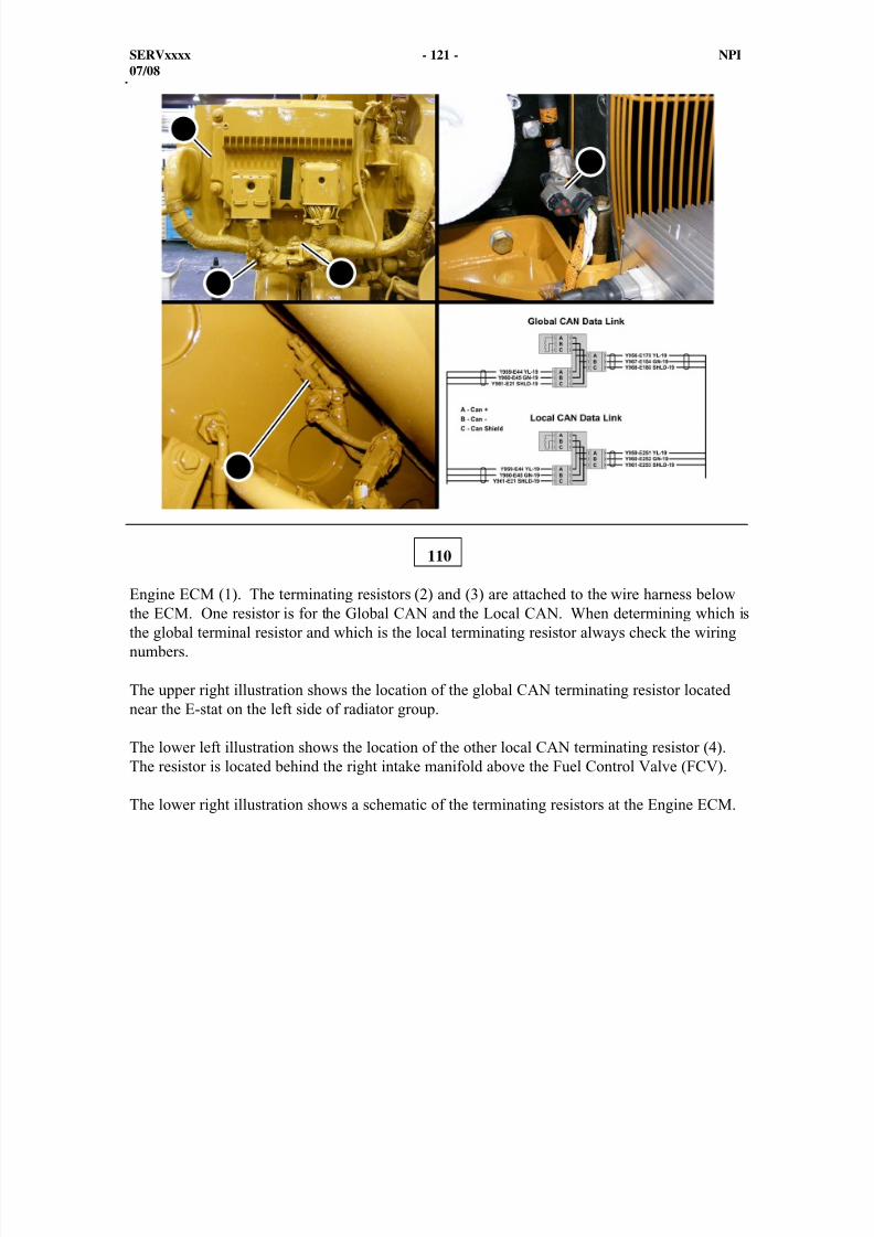
8/9/2019 797F HAA - Meeting Guide.pdf
http://slidepdf.com/reader/full/797f-haa-meeting-guidepdf 136/367
SERVxxxx - 121 - NPI07/08
Engine ECM (1). The terminating resistors (2) and (3) are attached to the wire harness belowthe ECM. One resistor is for the Global CAN and the Local CAN. When determining which isthe global terminal resistor and which is the local terminating resistor always check the wiringnumbers.
The upper right illustration shows the location of the global CAN terminating resistor locatednear the E-stat on the left side of radiator group.
The lower left illustration shows the location of the other local CAN terminating resistor (4).The resistor is located behind the right intake manifold above the Fuel Control Valve (FCV).
The lower right illustration shows a schematic of the terminating resistors at the Engine ECM.
110
1
2 3
4
5
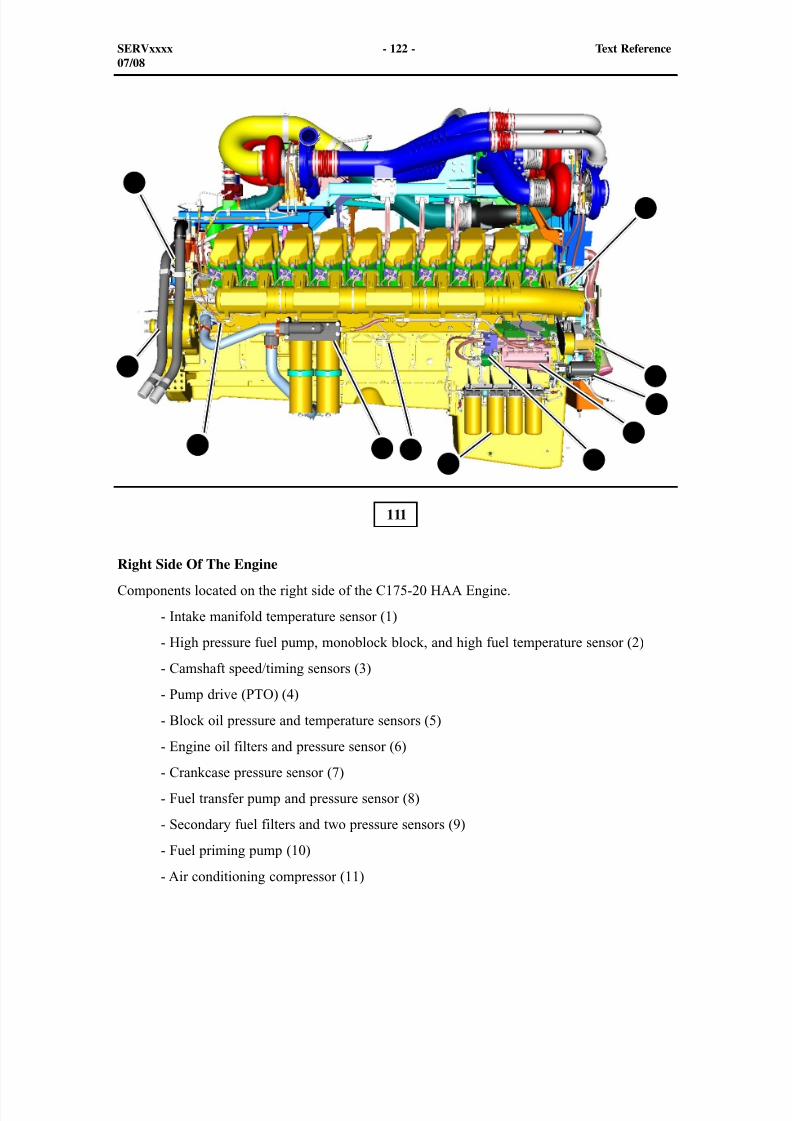
8/9/2019 797F HAA - Meeting Guide.pdf
http://slidepdf.com/reader/full/797f-haa-meeting-guidepdf 137/367
111
Right Side Of The Engine
Components located on the right side of the C175-20 HAA Engine.
- Intake manifold temperature sensor (1)
- High pressure fuel pump, monoblock block, and high fuel temperature sensor (2)
- Camshaft speed/timing sensors (3)
- Pump drive (PTO) (4)
- Block oil pressure and temperature sensors (5)
- Engine oil filters and pressure sensor (6)
- Crankcase pressure sensor (7)
- Fuel transfer pump and pressure sensor (8)
- Secondary fuel filters and two pressure sensors (9)
- Fuel priming pump (10)
- Air conditioning compressor (11)
1
2
3
4
5 6 789
10
11
SERVxxxx - 122 - Text Reference07/08
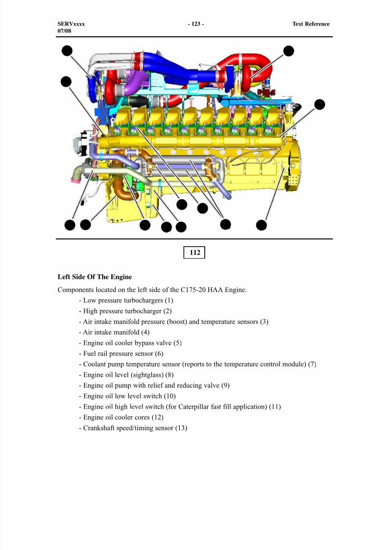
8/9/2019 797F HAA - Meeting Guide.pdf
http://slidepdf.com/reader/full/797f-haa-meeting-guidepdf 138/367
112
Left Side Of The Engine
Components located on the left side of the C175-20 HAA Engine.
- Low pressure turbochargers (1)
- High pressure turbocharger (2)
- Air intake manifold pressure (boost) and temperature sensors (3)
- Air intake manifold (4)
- Engine oil cooler bypass valve (5)
- Fuel rail pressure sensor (6)
- Coolant pump temperature sensor (reports to the temperature control module) (7)
- Engine oil level (sightglass) (8)
- Engine oil pump with relief and reducing valve (9)
- Engine oil low level switch (10)
- Engine oil high level switch (for Caterpillar fast fill application) (11)
- Engine oil cooler cores (12)
- Crankshaft speed/timing sensor (13)
3
6
7 138 10 11 129
5
21
4
SERVxxxx - 123 - Text Reference07/08
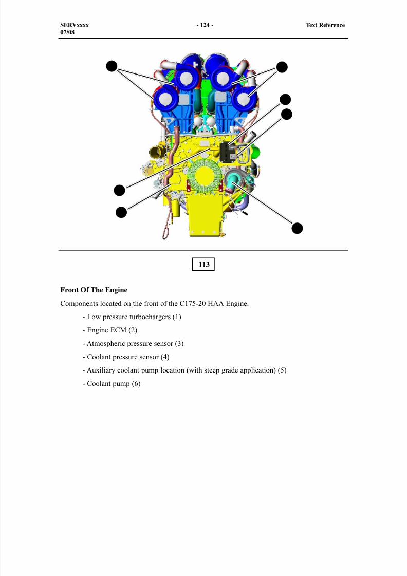
8/9/2019 797F HAA - Meeting Guide.pdf
http://slidepdf.com/reader/full/797f-haa-meeting-guidepdf 139/367
113
Front Of The Engine
Components located on the front of the C175-20 HAA Engine.
- Low pressure turbochargers (1)
- Engine ECM (2)
- Atmospheric pressure sensor (3)
- Coolant pressure sensor (4)
- Auxiliary coolant pump location (with steep grade application) (5)
- Coolant pump (6)
SERVxxxx - 124 - Text Reference07/08
11
2
3
6
4
5
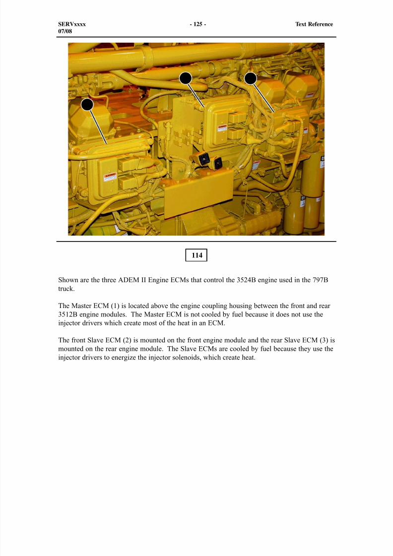
8/9/2019 797F HAA - Meeting Guide.pdf
http://slidepdf.com/reader/full/797f-haa-meeting-guidepdf 140/367
2
1 3
114
Shown are the three ADEM II Engine ECMs that control the 3524B engine used in the 797Btruck.
The Master ECM (1) is located above the engine coupling housing between the front and rear3512B engine modules. The Master ECM is not cooled by fuel because it does not use theinjector drivers which create most of the heat in an ECM.
The front Slave ECM (2) is mounted on the front engine module and the rear Slave ECM (3) ismounted on the rear engine module. The Slave ECMs are cooled by fuel because they use theinjector drivers to energize the injector solenoids, which create heat.
SERVxxxx - 125 - Text Reference07/08
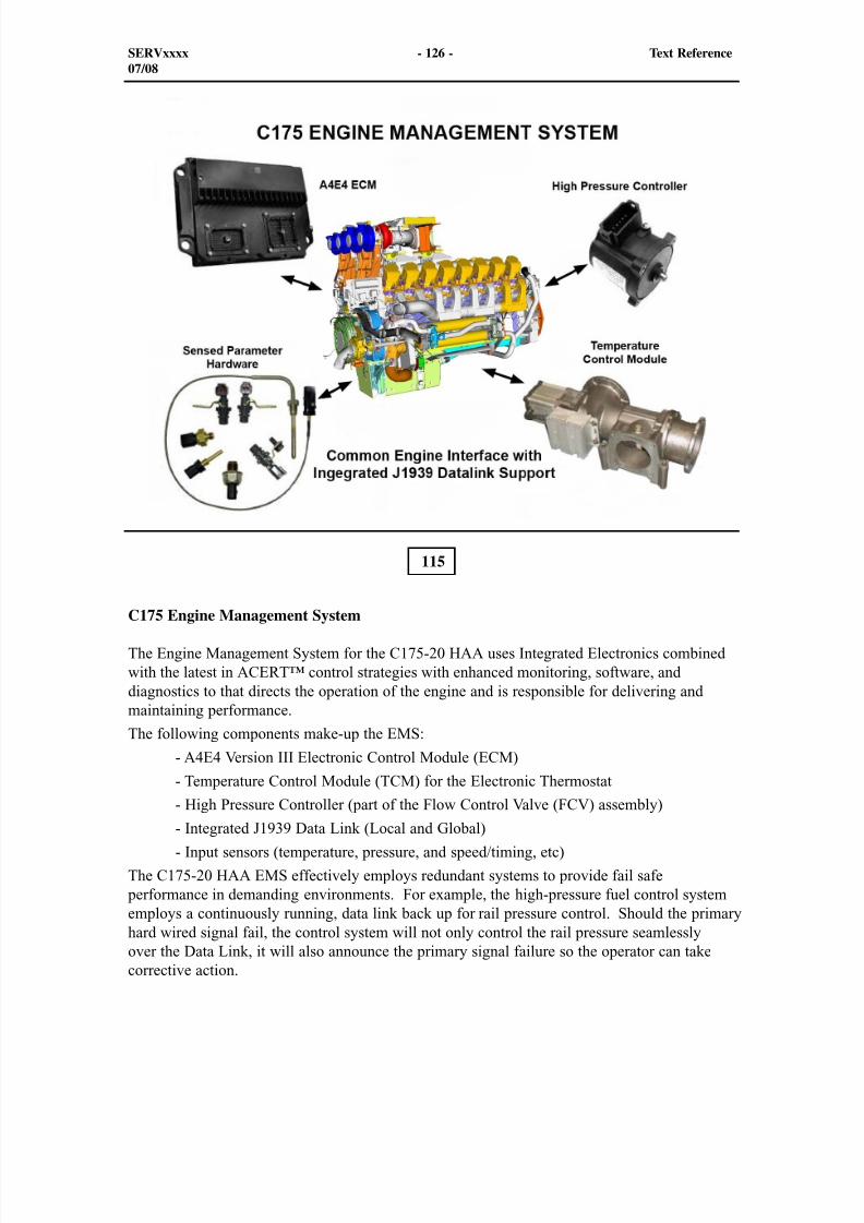
8/9/2019 797F HAA - Meeting Guide.pdf
http://slidepdf.com/reader/full/797f-haa-meeting-guidepdf 141/367
115
C175 Engine Management System
The Engine Management System for the C175-20 HAA uses Integrated Electronics combinedwith the latest in ACERT™ control strategies with enhanced monitoring, software, anddiagnostics to that directs the operation of the engine and is responsible for delivering andmaintaining performance.
The following components make-up the EMS:
- A4E4 Version III Electronic Control Module (ECM)
- Temperature Control Module (TCM) for the Electronic Thermostat
- High Pressure Controller (part of the Flow Control Valve (FCV) assembly) - Integrated J1939 Data Link (Local and Global)
- Input sensors (temperature, pressure, and speed/timing, etc)
The C175-20 HAA EMS effectively employs redundant systems to provide fail safe performance in demanding environments. For example, the high-pressure fuel control systememploys a continuously running, data link back up for rail pressure control. Should the primaryhard wired signal fail, the control system will not only control the rail pressure seamlesslyover the Data Link, it will also announce the primary signal failure so the operator can takecorrective action.
SERVxxxx - 126 - Text Reference07/08
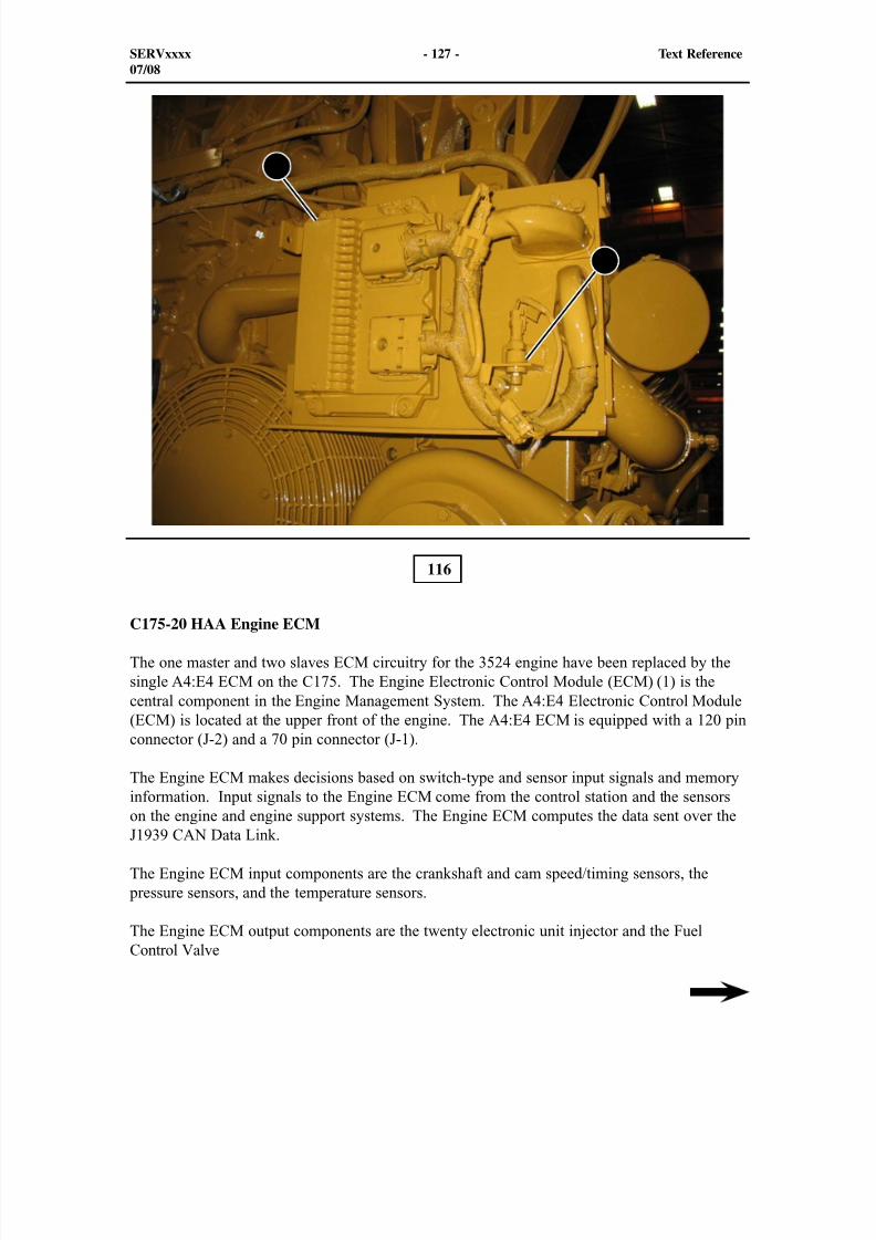
8/9/2019 797F HAA - Meeting Guide.pdf
http://slidepdf.com/reader/full/797f-haa-meeting-guidepdf 142/367
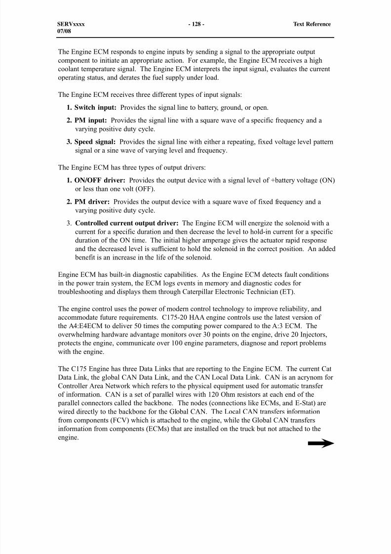
8/9/2019 797F HAA - Meeting Guide.pdf
http://slidepdf.com/reader/full/797f-haa-meeting-guidepdf 143/367
The Engine ECM responds to engine inputs by sending a signal to the appropriate outputcomponent to initiate an appropriate action. For example, the Engine ECM receives a highcoolant temperature signal. The Engine ECM interprets the input signal, evaluates the currentoperating status, and derates the fuel supply under load.
The Engine ECM receives three different types of input signals:
1. Switch input: Provides the signal line to battery, ground, or open.
2. PM input: Provides the signal line with a square wave of a specific frequency and avarying positive duty cycle.
3. Speed signal: Provides the signal line with either a repeating, fixed voltage level patternsignal or a sine wave of varying level and frequency.
The Engine ECM has three types of output drivers:
1. ON/OFF driver: Provides the output device with a signal level of +battery voltage (ON)or less than one volt (OFF).
2. PM driver: Provides the output device with a square wave of fixed frequency and avarying positive duty cycle.
3. Controlled current output driver: The Engine ECM will energize the solenoid with acurrent for a specific duration and then decrease the level to hold-in current for a specificduration of the ON time. The initial higher amperage gives the actuator rapid responseand the decreased level is sufficient to hold the solenoid in the correct position. An added
benefit is an increase in the life of the solenoid.
Engine ECM has built-in diagnostic capabilities. As the Engine ECM detects fault conditionsin the power train system, the ECM logs events in memory and diagnostic codes fortroubleshooting and displays them through Caterpillar Electronic Technician (ET).
The engine control uses the power of modern control technology to improve reliability, andaccommodate future requirements. C175-20 HAA engine controls use the latest version ofthe A4:E4ECM to deliver 50 times the computing power compared to the A:3 ECM. Theoverwhelming hardware advantage monitors over 30 points on the engine, drive 20 Injectors,
protects the engine, communicate over 100 engine parameters, diagnose and report problemswith the engine.
The C175 Engine has three Data Links that are reporting to the Engine ECM. The current CatData Link, the global CAN Data Link, and the CAN Local Data Link. CAN is an acrynom forController Area Network which refers to the physical equipment used for automatic transferof information. CAN is a set of parallel wires with 120 Ohm resistors at each end of the
parallel connectors called the backbone. The nodes (connections like ECMs, and E-Stat) arewired directly to the backbone for the Global CAN. The Local CAN transfers informationfrom components (FCV) which is attached to the engine, while the Global CAN transfersinformation from components (ECMs) that are installed on the truck but not attached to theengine.
SERVxxxx - 128 - Text Reference07/08
8/9/2019 797F HAA - Meeting Guide.pdf
http://slidepdf.com/reader/full/797f-haa-meeting-guidepdf 144/367
The atmospheric pressure sensor (2) is located on the control panel next to the Engine ECM.The function of the atmospheric pressure sensor is to supply the altitude level back to theEngine ECM in order to calculate gauge pressure for all the pressure sensors to the ECM.Losing the signal from the atmospheric pressure sensor will initiate a 10% derate.
The atmospheric pressure sensor is one of the many analog sensors that receive a regulated5.0 ± 0.5 volts from the Engine ECM. The atmospheric pressure sensor output signal is a DCVoltage output signal that varies between 0.2 and 4.8 Volts DC with an operating pressure range
between 0 and 111 kPa (0 and 16.1 psi).The following diagnostic codes are logged when the atmospheric pressure sensor is damaged ormalfunctioning.
- CID 274 - FMI 3 - Atmos. Press. Voltage above normal
- CID 274 - FMI 4 - Atmos. Press. Voltage below normal
When troubleshooting an analog pressure sensor, check the output signal of the sensors, by
connecting a multimeter between the B and C pins of the sensor connector. Set the meter toread DC Volts. The DC Voltage output of the atmospheric pressure sensor should be between0.2 and 4.8 Volts DC.
Pressure Sensor Calibration: Normally, at 0 rpm and 2 seconds after start, the Engine ECM goes out to each pressure sensorto ensure the pressure is within tolerance of a specified value. If the value is within tolerance,the Engine ECM compares the value of the pressure sensor with the atmospheric sensor andassigns a specific offset value to that sensor for calibration.
NOTE: The signal from the atmospheric pressure sensor is used by the Engine ECMto calculate a number of pressure measurements in most electronic engines. The signal
from the atmospheric pressure sensor is compared to the signal from the other engine pressure sensors to calibrate the pressure sensors. When the Engine ECM is poweredup, the ECM uses the signal from the atmospheric pressure sensor as a reference point
for calibration of the other pressure sensors on the engine.
SERVxxxx - 129 - Text Reference07/08
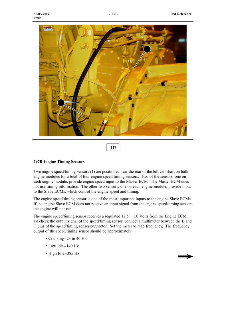
8/9/2019 797F HAA - Meeting Guide.pdf
http://slidepdf.com/reader/full/797f-haa-meeting-guidepdf 145/367
117
797B Engine Timing Sensors
Two engine speed/timing sensors (1) are positioned near the rear of the left camshaft on bothengine modules for a total of four engine speed timing sensors. Two of the sensors, one oneach engine module, provide engine speed input to the Master ECM. The Master ECM doesnot use timing information. The other two sensors, one on each engine module, provide inputto the Slave ECMs, which control the engine speed and timing.
The engine speed/timing sensor is one of the most important inputs to the engine Slave ECMs.If the engine Slave ECM does not receive an input signal from the engine speed/timing sensors,
the engine will not run.The engine speed/timing sensor receives a regulated 12.5 ± 1.0 Volts from the Engine ECM.To check the output signal of the speed/timing sensor, connect a multimeter between the B andC pins of the speed/timing sensor connector. Set the meter to read frequency. The frequencyoutput of the speed/timing sensor should be approximately:
• Cranking--23 to 40 Hz
• Low Idle--140 Hz
• High Idle--385 Hz
SERVxxxx - 130 - Text Reference07/08
2
1
8/9/2019 797F HAA - Meeting Guide.pdf
http://slidepdf.com/reader/full/797f-haa-meeting-guidepdf 146/367
When viewing engine speed in the ET status screen, cranking speed should be between 100 and250 rpm.
A passive (two wire) engine speed sensor (2) is positioned on top of the rear engine moduleflywheel housing. The passive speed sensor uses the passing teeth of the flywheel to provide afrequency output. The passive speed sensor sends the engine speed signal to the Transmissionand Brake/Cooling ECMs.
The signal from the passive speed sensor is used for several purposes.
- Torque converter lockup clutch slippage monitoring
- Shift time calculations
- Transmission Output Speed (TOS) ratification
- Transmission clutch slippage monitoring
- Automatic Retarder Control (ARC) engine control speed
- Engine running signal for hoist operation
The output signal of the passive speed sensor can also be checked by connecting a multimeter between the two pins of the speed sensor connector and setting the meter to read frequency.
NOTE: Turn ON the engine shutdown switch during the cranking test to prevent theengine from starting. The cranking speed and frequency output will vary depending onweather and machine conditions. When viewing engine speed in the ET status screen,cranking speed should be between 100 and 250 rpm.
SERVxxxx - 131 - Text Reference07/08
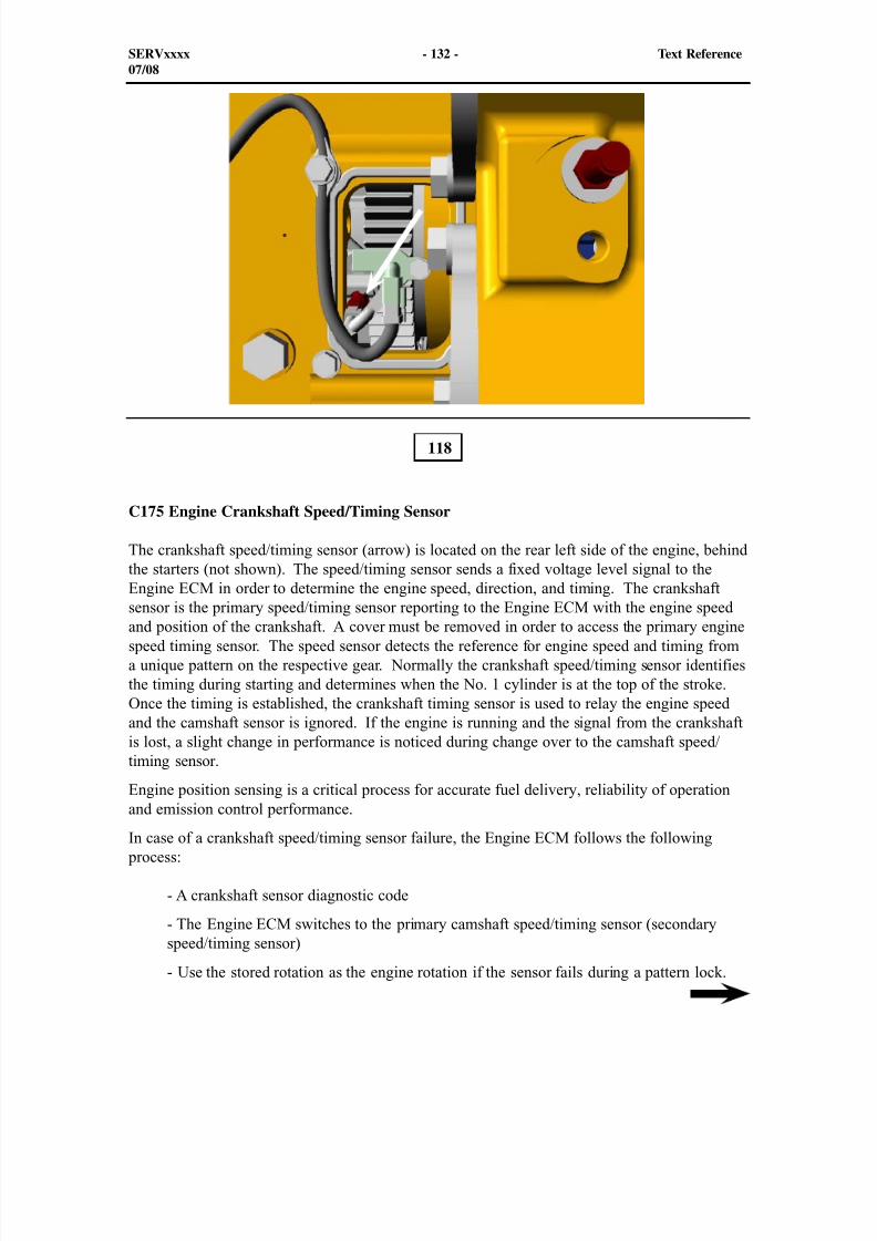
8/9/2019 797F HAA - Meeting Guide.pdf
http://slidepdf.com/reader/full/797f-haa-meeting-guidepdf 147/367
C175 Engine Crankshaft Speed/Timing Sensor
The crankshaft speed/timing sensor (arrow) is located on the rear left side of the engine, behindthe starters (not shown). The speed/timing sensor sends a fixed voltage level signal to theEngine ECM in order to determine the engine speed, direction, and timing. The crankshaft
sensor is the primary speed/timing sensor reporting to the Engine ECM with the engine speedand position of the crankshaft. A cover must be removed in order to access the primary enginespeed timing sensor. The speed sensor detects the reference for engine speed and timing froma unique pattern on the respective gear. Normally the crankshaft speed/timing sensor identifiesthe timing during starting and determines when the No. 1 cylinder is at the top of the stroke.Once the timing is established, the crankshaft timing sensor is used to relay the engine speedand the camshaft sensor is ignored. If the engine is running and the signal from the crankshaftis lost, a slight change in performance is noticed during change over to the camshaft speed/timing sensor.
Engine position sensing is a critical process for accurate fuel delivery, reliability of operation
and emission control performance.In case of a crankshaft speed/timing sensor failure, the Engine ECM follows the following
process:
- A crankshaft sensor diagnostic code
- The Engine ECM switches to the primary camshaft speed/timing sensor (secondaryspeed/timing sensor)
- Use the stored rotation as the engine rotation if the sensor fails during a pattern lock.
118
SERVxxxx - 132 - Text Reference07/08

8/9/2019 797F HAA - Meeting Guide.pdf
http://slidepdf.com/reader/full/797f-haa-meeting-guidepdf 148/367
The crankshaft speed/timing sensor serves four functions:
- Engine speed measurement
- Engine timing measurement
- TDC location and cylinder number identification
- Reverse rotation protection
There is no adjustment made by the technician. The sensor adjustment is preset.
If the engine is running for three seconds and the pattern from the timing ring is lost for twoseconds, the Engine ECM will log the following Diagnostic Code for the crankshaft speed/timing sensor:
- CID 190 - FMI 8 Engine speed signal abnormal - Check the crankshaft speed/timingsensor and the wiring.
SERVxxxx - 133 - Text Reference07/08
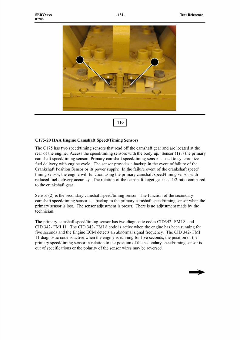
8/9/2019 797F HAA - Meeting Guide.pdf
http://slidepdf.com/reader/full/797f-haa-meeting-guidepdf 149/367
12
C175-20 HAA Engine Camshaft Speed/Timing Sensors
The C175 has two speed/timing sensors that read off the camshaft gear and are located at therear of the engine. Access the speed/timing sensors with the body up. Sensor (1) is the primarycamshaft speed/timing sensor. Primary camshaft speed/timing sensor is used to synchronizefuel delivery with engine cycle. The sensor provides a backup in the event of failure of theCrankshaft Position Sensor or its power supply. In the failure event of the crankshaft speed/timing sensor, the engine will function using the primary camshaft speed/timing sensor withreduced fuel delivery accuracy. The rotation of the camshaft target gear is a 1:2 ratio comparedto the crankshaft gear.
Sensor (2) is the secondary camshaft speed/timing sensor. The function of the secondarycamshaft speed/timing sensor is a backup to the primary camshaft speed/timing sensor when the
primary sensor is lost. The sensor adjustment is preset. There is no adjustment made by thetechnician.
The primary camshaft speed/timing sensor has two diagnostic codes CID342- FMI 8 andCID 342- FMI 11. The CID 342- FMI 8 code is active when the engine has been running forfive seconds and the Engine ECM detects an abnormal signal frequency. The CID 342- FMI11 diagnostic code is active when the engine is running for five seconds, the position of the
primary speed/timing sensor in relation to the position of the secondary speed/timing sensor isout of specifications or the polarity of the sensor wires may be reversed.
119
SERVxxxx - 134 - Text Reference07/08

8/9/2019 797F HAA - Meeting Guide.pdf
http://slidepdf.com/reader/full/797f-haa-meeting-guidepdf 150/367
The secondary camshaft speed/timing sensor (tertiary) has two diagnostic codes:CID 2710 - FMI 8 Tertiary engine speed/timing sensor and CID 2710 - FMI 11 Tertiary enginespeed/timing sensor. The CID 2710 - FMI 8 code is active when the engine has been runningfor five seconds and the Engine ECM detects an abnormal signal frequency.
The CID 2710 - FMI 11 diagnostic code is active when the engine is running for five seconds,the position of the primary speed/timing sensor in relation to the position of the secondaryspeed/timing sensor is out of specifications or the polarity of the sensor wires may be reversed.
SERVxxxx - 135 - Text Reference07/08
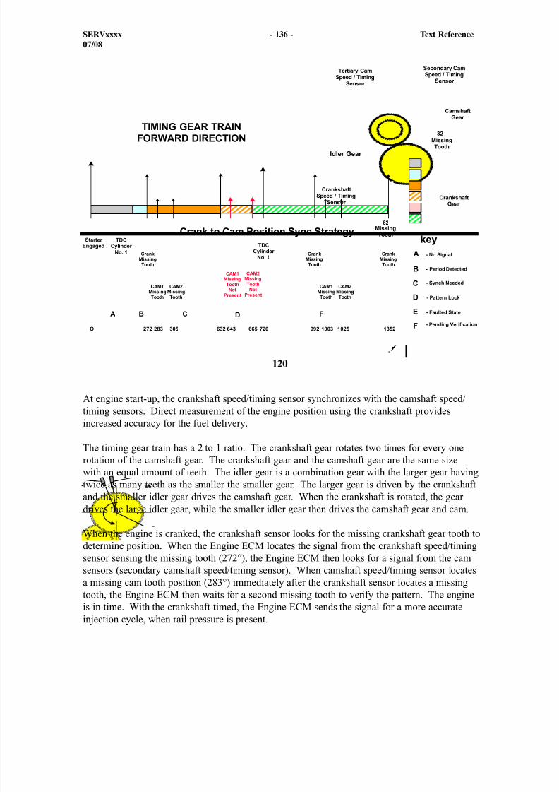
8/9/2019 797F HAA - Meeting Guide.pdf
http://slidepdf.com/reader/full/797f-haa-meeting-guidepdf 151/367
120
At engine start-up, the crankshaft speed/timing sensor synchronizes with the camshaft speed/timing sensors. Direct measurement of the engine position using the crankshaft providesincreased accuracy for the fuel delivery.
The timing gear train has a 2 to 1 ratio. The crankshaft gear rotates two times for every onerotation of the camshaft gear. The crankshaft gear and the camshaft gear are the same sizewith an equal amount of teeth. The idler gear is a combination gear with the larger gear havingtwice as many teeth as the smaller the smaller gear. The larger gear is driven by the crankshaftand the smaller idler gear drives the camshaft gear. When the crankshaft is rotated, the geardrives the large idler gear, while the smaller idler gear then drives the camshaft gear and cam.
When the engine is cranked, the crankshaft sensor looks for the missing crankshaft gear tooth todetermine position. When the Engine ECM locates the signal from the crankshaft speed/timingsensor sensing the missing tooth (272°), the Engine ECM then looks for a signal from the camsensors (secondary camshaft speed/timing sensor). When camshaft speed/timing sensor locatesa missing cam tooth position (283°) immediately after the crankshaft sensor locates a missingtooth, the Engine ECM then waits for a second missing tooth to verify the pattern. The engineis in time. With the crankshaft timed, the Engine ECM sends the signal for a more accurateinjection cycle, when rail pressure is present.
SERVxxxx - 136 - Text Reference07/08
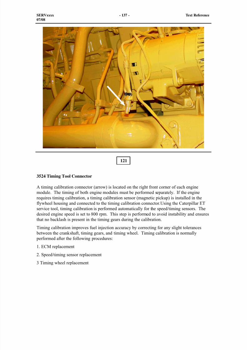
8/9/2019 797F HAA - Meeting Guide.pdf
http://slidepdf.com/reader/full/797f-haa-meeting-guidepdf 152/367
121
3524 Timing Tool Connector
A timing calibration connector (arrow) is located on the right front corner of each enginemodule. The timing of both engine modules must be performed separately. If the enginerequires timing calibration, a timing calibration sensor (magnetic pickup) is installed in theflywheel housing and connected to the timing calibration connector.Using the Caterpillar ETservice tool, timing calibration is performed automatically for the speed/timing sensors. Thedesired engine speed is set to 800 rpm. This step is performed to avoid instability and ensuresthat no backlash is present in the timing gears during the calibration.
Timing calibration improves fuel injection accuracy by correcting for any slight tolerances between the crankshaft, timing gears, and timing wheel. Timing calibration is normally performed after the following procedures:
1. ECM replacement
2. Speed/timing sensor replacement
3 Timing wheel replacement
SERVxxxx - 137 - Text Reference07/08
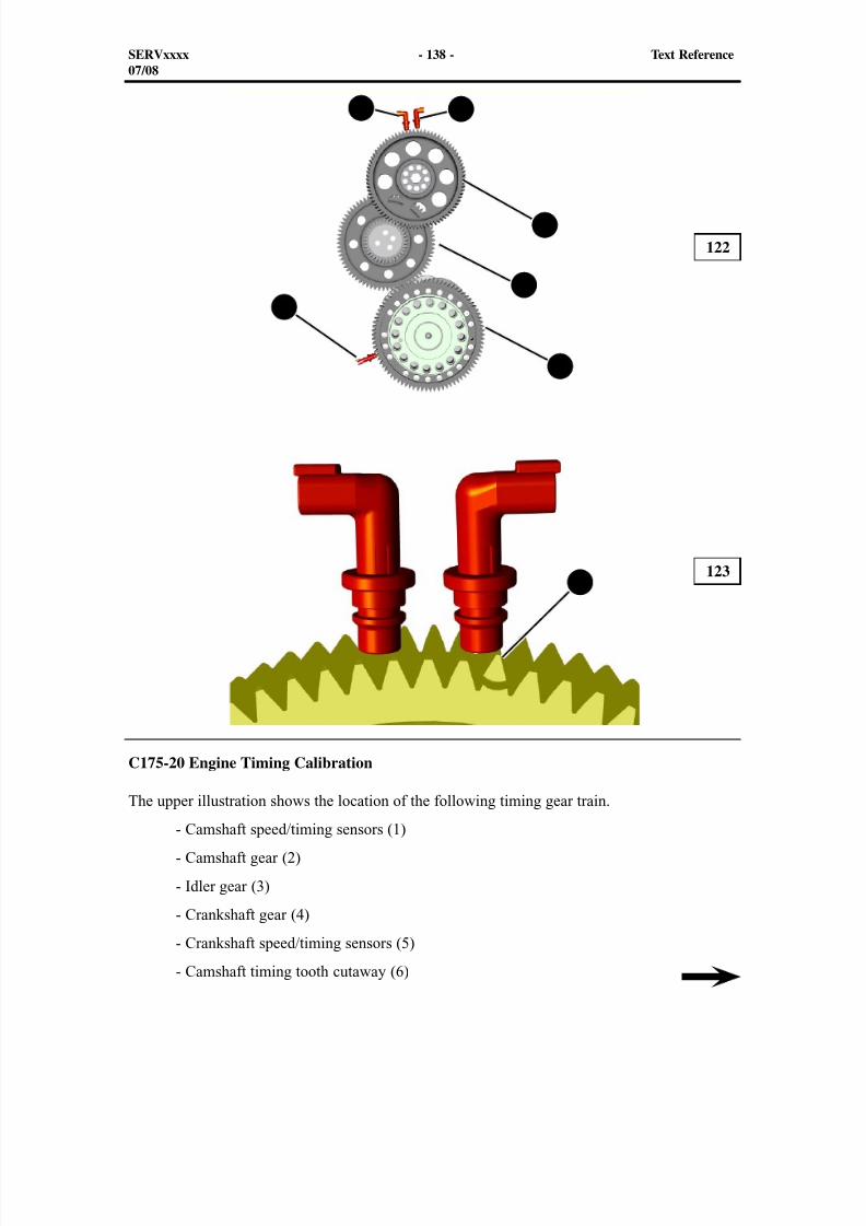
8/9/2019 797F HAA - Meeting Guide.pdf
http://slidepdf.com/reader/full/797f-haa-meeting-guidepdf 153/367
C175-20 Engine Timing Calibration
The upper illustration shows the location of the following timing gear train. - Camshaft speed/timing sensors (1)
- Camshaft gear (2)
- Idler gear (3)
- Crankshaft gear (4)
- Crankshaft speed/timing sensors (5)
- Camshaft timing tooth cutaway (6)
122
123
SERVxxxx - 138 - Text Reference07/08
1
2
3
4
5
6
1
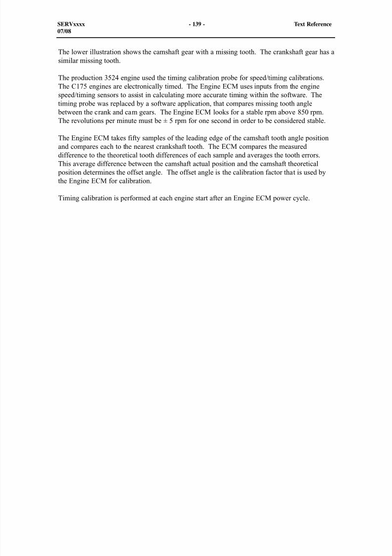
8/9/2019 797F HAA - Meeting Guide.pdf
http://slidepdf.com/reader/full/797f-haa-meeting-guidepdf 154/367
The lower illustration shows the camshaft gear with a missing tooth. The crankshaft gear has asimilar missing tooth.
The production 3524 engine used the timing calibration probe for speed/timing calibrations.The C175 engines are electronically timed. The Engine ECM uses inputs from the enginespeed/timing sensors to assist in calculating more accurate timing within the software. Thetiming probe was replaced by a software application, that compares missing tooth angle
between the crank and cam gears. The Engine ECM looks for a stable rpm above 850 rpm.The revolutions per minute must be ± 5 rpm for one second in order to be considered stable.
The Engine ECM takes fifty samples of the leading edge of the camshaft tooth angle positionand compares each to the nearest crankshaft tooth. The ECM compares the measureddifference to the theoretical tooth differences of each sample and averages the tooth errors.This average difference between the camshaft actual position and the camshaft theoretical
position determines the offset angle. The offset angle is the calibration factor that is used by
the Engine ECM for calibration.
Timing calibration is performed at each engine start after an Engine ECM power cycle.
SERVxxxx - 139 - Text Reference07/08
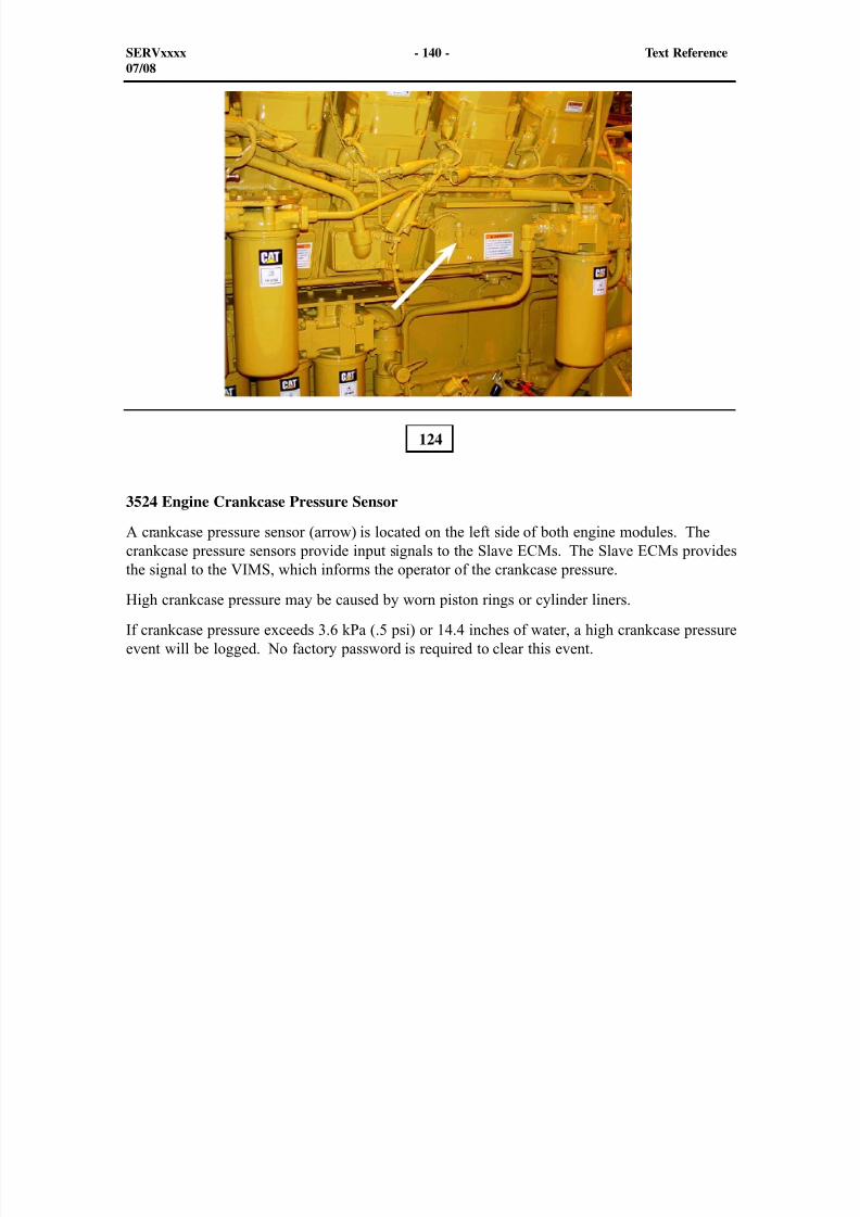
8/9/2019 797F HAA - Meeting Guide.pdf
http://slidepdf.com/reader/full/797f-haa-meeting-guidepdf 155/367
3524 Engine Crankcase Pressure Sensor
A crankcase pressure sensor (arrow) is located on the left side of both engine modules. Thecrankcase pressure sensors provide input signals to the Slave ECMs. The Slave ECMs providesthe signal to the VIMS, which informs the operator of the crankcase pressure.
High crankcase pressure may be caused by worn piston rings or cylinder liners.
If crankcase pressure exceeds 3.6 kPa (.5 psi) or 14.4 inches of water, a high crankcase pressureevent will be logged. No factory password is required to clear this event.
124
SERVxxxx - 140 - Text Reference07/08
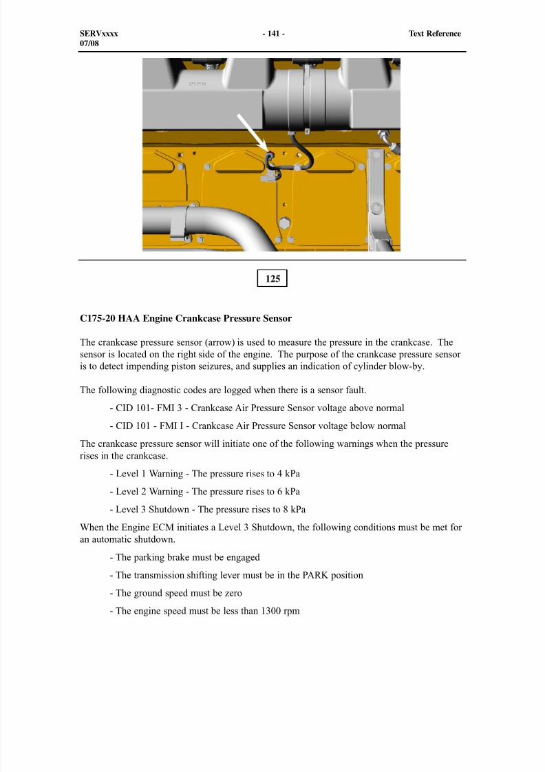
8/9/2019 797F HAA - Meeting Guide.pdf
http://slidepdf.com/reader/full/797f-haa-meeting-guidepdf 156/367
C175-20 HAA Engine Crankcase Pressure Sensor
The crankcase pressure sensor (arrow) is used to measure the pressure in the crankcase. Thesensor is located on the right side of the engine. The purpose of the crankcase pressure sensoris to detect impending piston seizures, and supplies an indication of cylinder blow-by.
The following diagnostic codes are logged when there is a sensor fault.
- CID 101- FMI 3 - Crankcase Air Pressure Sensor voltage above normal
- CID 101 - FMI I - Crankcase Air Pressure Sensor voltage below normal
The crankcase pressure sensor will initiate one of the following warnings when the pressurerises in the crankcase.
- Level 1 Warning - The pressure rises to 4 kPa
- Level 2 Warning - The pressure rises to 6 kPa
- Level 3 Shutdown - The pressure rises to 8 kPa
When the Engine ECM initiates a Level 3 Shutdown, the following conditions must be met foran automatic shutdown.
- The parking brake must be engaged
- The transmission shifting lever must be in the PARK position
- The ground speed must be zero
- The engine speed must be less than 1300 rpm
125
SERVxxxx - 141 - Text Reference07/08
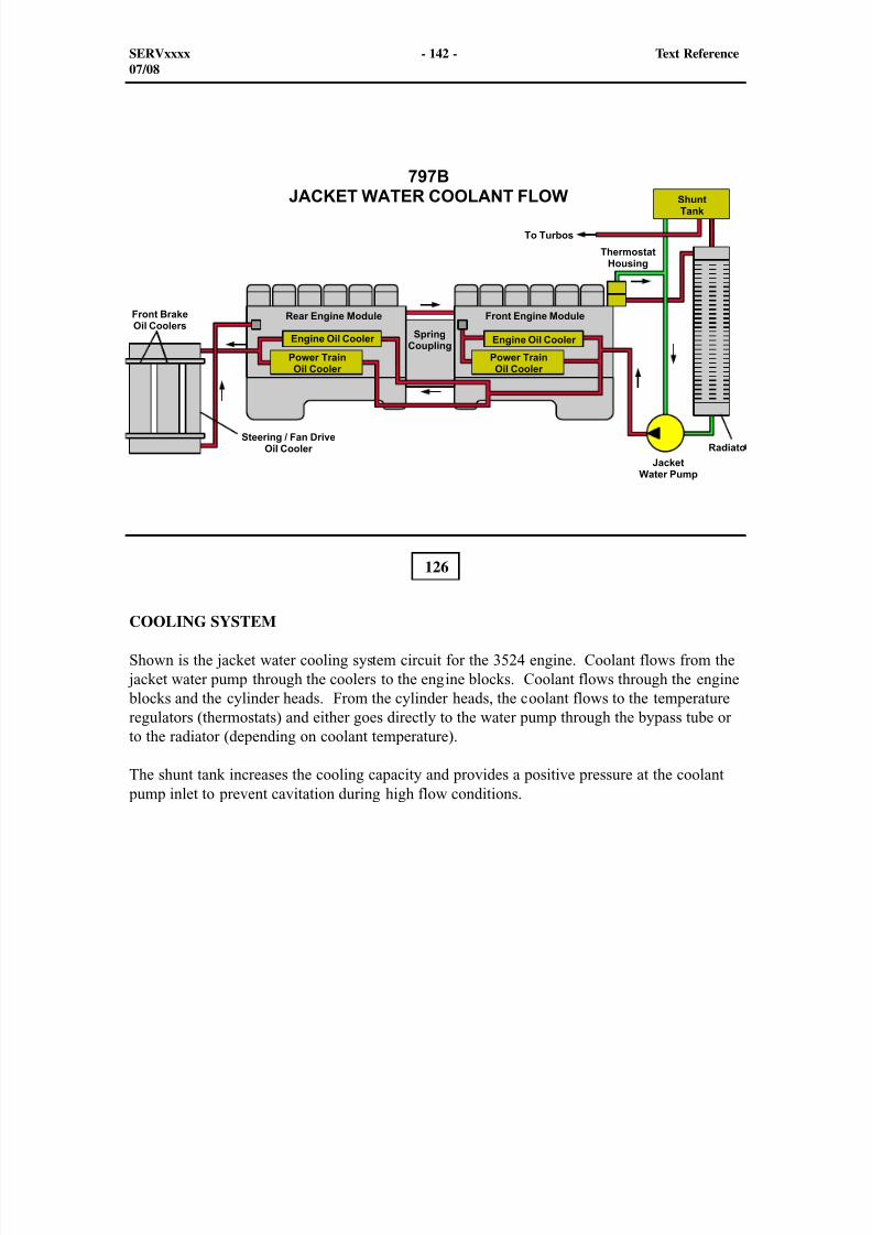
8/9/2019 797F HAA - Meeting Guide.pdf
http://slidepdf.com/reader/full/797f-haa-meeting-guidepdf 157/367
126
COOLING SYSTEM
Shown is the jacket water cooling system circuit for the 3524 engine. Coolant flows from the jacket water pump through the coolers to the engine blocks. Coolant flows through the engine blocks and the cylinder heads. From the cylinder heads, the coolant flows to the temperatureregulators (thermostats) and either goes directly to the water pump through the bypass tube orto the radiator (depending on coolant temperature).
The shunt tank increases the cooling capacity and provides a positive pressure at the coolant pump inlet to prevent cavitation during high flow conditions.
SERVxxxx - 142 - Text Reference07/08
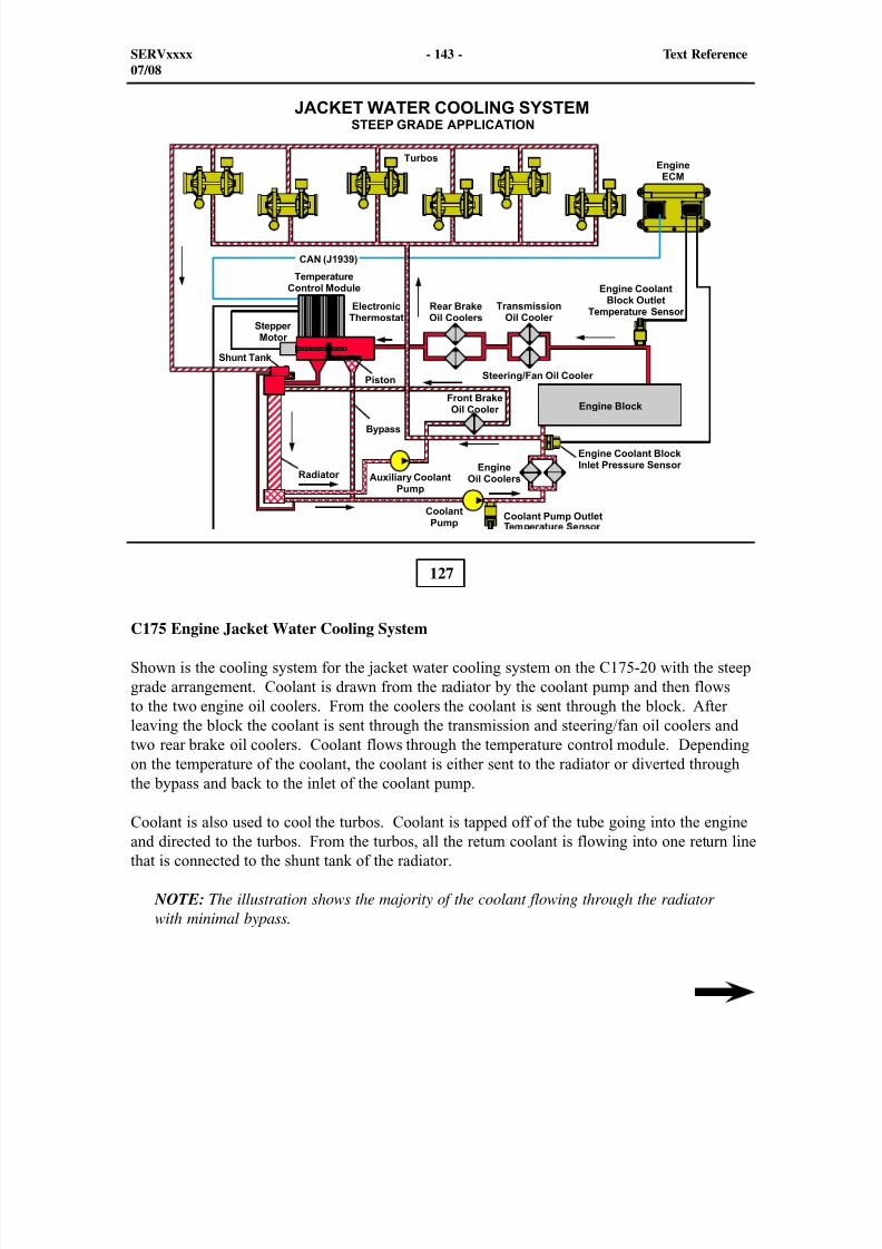
8/9/2019 797F HAA - Meeting Guide.pdf
http://slidepdf.com/reader/full/797f-haa-meeting-guidepdf 158/367
127
C175 Engine Jacket Water Cooling System
Shown is the cooling system for the jacket water cooling system on the C175-20 with the steepgrade arrangement. Coolant is drawn from the radiator by the coolant pump and then flowsto the two engine oil coolers. From the coolers the coolant is sent through the block. Afterleaving the block the coolant is sent through the transmission and steering/fan oil coolers andtwo rear brake oil coolers. Coolant flows through the temperature control module. Dependingon the temperature of the coolant, the coolant is either sent to the radiator or diverted throughthe bypass and back to the inlet of the coolant pump.
Coolant is also used to cool the turbos. Coolant is tapped off of the tube going into the engineand directed to the turbos. From the turbos, all the return coolant is flowing into one return linethat is connected to the shunt tank of the radiator.
NOTE: The illustration shows the majority of the coolant flowing through the radiatorwith minimal bypass.
SERVxxxx - 143 - Text Reference07/08

8/9/2019 797F HAA - Meeting Guide.pdf
http://slidepdf.com/reader/full/797f-haa-meeting-guidepdf 159/367
The auxiliary pump draws coolant from the radiator and sends the coolant to the front brake oilcooler. The coolant flows through the cooler and back to the radiator.
SERVxxxx - 144 - Text Reference07/08
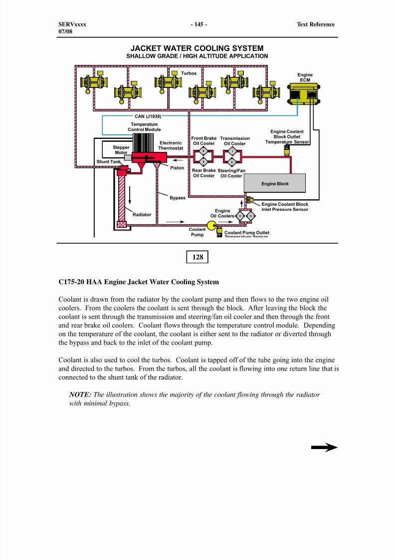
8/9/2019 797F HAA - Meeting Guide.pdf
http://slidepdf.com/reader/full/797f-haa-meeting-guidepdf 160/367
128
C175-20 HAA Engine Jacket Water Cooling System
Coolant is drawn from the radiator by the coolant pump and then flows to the two engine oilcoolers. From the coolers the coolant is sent through the block. After leaving the block thecoolant is sent through the transmission and steering/fan oil cooler and then through the frontand rear brake oil coolers. Coolant flows through the temperature control module. Dependingon the temperature of the coolant, the coolant is either sent to the radiator or diverted throughthe bypass and back to the inlet of the coolant pump.
Coolant is also used to cool the turbos. Coolant is tapped off of the tube going into the engineand directed to the turbos. From the turbos, all the coolant is flowing into one return line that isconnected to the shunt tank of the radiator.
NOTE: The illustration shows the majority of the coolant flowing through the radiatorwith minimal bypass.
SERVxxxx - 145 - Text Reference07/08
8/9/2019 797F HAA - Meeting Guide.pdf
http://slidepdf.com/reader/full/797f-haa-meeting-guidepdf 161/367
The Electronic Thermostat (E-Stat) monitors the flow of coolant between the bypass tube andthe radiator with a piston and a stepper motor. The E-Stat is set to regulate coolant pumpoutlet temperature to 85° C (185° F). The coolant pump outlet temperature sensor measuresthe temperature of the coolant that is flowing into the coolers and reports the temperature tothe temperature control module. As the coolant temperature increases, the temperature controlmodule sends current to the stepper motor to move the piston, closing the coolant bypass andallowing more flow through the radiator. As the coolant temperature decreases, the temperaturecontrol module sends a current to the stepper motor to move the piston, closing down the flowto the left through the radiator and allowing more coolant to flow through the bypass.
Located in the outlet of the coolant pump is coolant pump outlet temperature sensor. Thesensor is connected directly to the E-stat control. From the E-Stat control coolant temperatureis sent over the Global CAN data link (J1939) to the Engine ECM. The engine coolant blockinlet pressure sensor and the engine coolant block outlet temperatue sensor are connecteddirectly to the Engine ECM.
At power-up of the engine, the stepper motor/piston position needs to be reset. The steppermotor is commanded to move to full stroke plus a configured overshoot to insure the reset
position is reached. The stepper motor drives the piston to the configured stop, typically the100% bypass position. As the piston reaches the stop, a ratcheting sound is heard. The pistonhas hit the stop. The stepper motor/piston may ratchet as many as 80 times to reach the default
position.
Also, the output temperature for the coolant pump will be sent over the CAN Data Link to theEngine ECM. From the Engine ECM, the coolant temperature will then be sent over the CatData Link to the Brake ECM to assist the fan system strategy for the requested fan speed. Thecoolant pump outlet temperature sensor is used a one of the key target temperatures for thehydraulic fan system. When the coolant pump outlet temperature sensor reads a temperature
below 79° C (174° F), the hydraulic fan system will not be affected by the temperature ofthe coolant. If the temperature increases over the key target temperature, the fan speed willincrease above the 325 rpm. If the coolant temperature increases over 84° C (183° F) to 525rpm for the shallow grade and 575 rpm for the steep grade.
The coolant pump outlet temperature is not the only temperature used as key targettemperatures for the hydraulic fan system. The highest of any of these two intake manifoldtemperature, the transmission lube temperature, the torque converter oil temperature, and/or the
brake temperature are used in the fan system strategy which is similar to the "B" Series truck.
SERVxxxx - 146 - Text Reference07/08
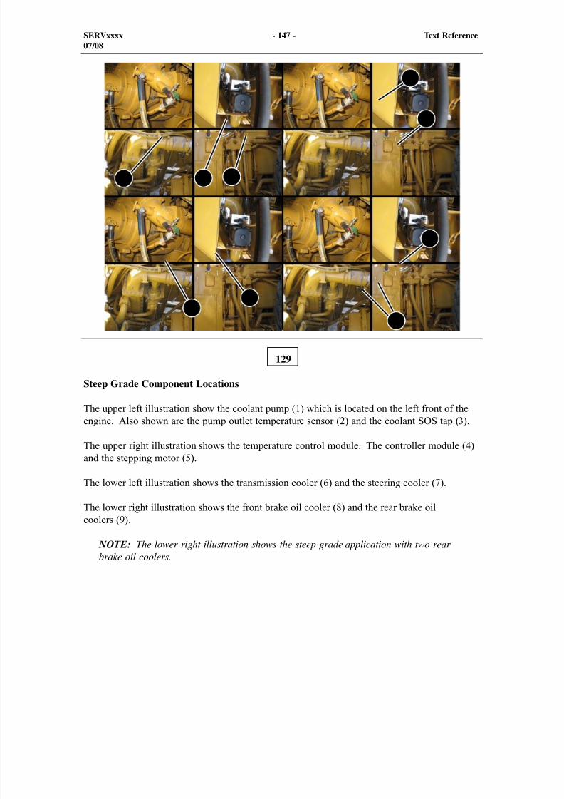
8/9/2019 797F HAA - Meeting Guide.pdf
http://slidepdf.com/reader/full/797f-haa-meeting-guidepdf 162/367
1 2 3
4
5
67
8
9
129
SERVxxxx - 147 - Text Reference07/08
Steep Grade Component Locations
The upper left illustration show the coolant pump (1) which is located on the left front of theengine. Also shown are the pump outlet temperature sensor (2) and the coolant SOS tap (3).
The upper right illustration shows the temperature control module. The controller module (4)and the stepping motor (5).
The lower left illustration shows the transmission cooler (6) and the steering cooler (7).
The lower right illustration shows the front brake oil cooler (8) and the rear brake oil
coolers (9). NOTE: The lower right illustration shows the steep grade application with two rearbrake oil coolers.
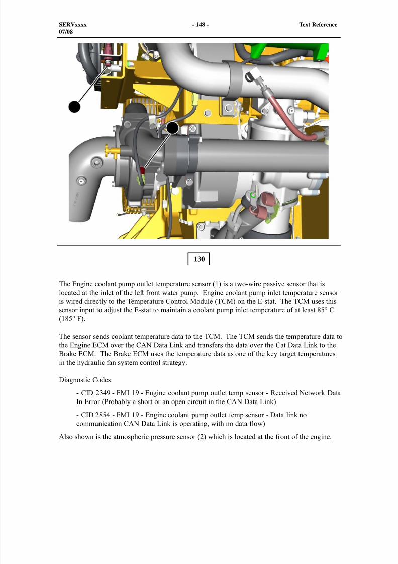
8/9/2019 797F HAA - Meeting Guide.pdf
http://slidepdf.com/reader/full/797f-haa-meeting-guidepdf 163/367
1
2
130
The Engine coolant pump outlet temperature sensor (1) is a two-wire passive sensor that islocated at the inlet of the left front water pump. Engine coolant pump inlet temperature sensoris wired directly to the Temperature Control Module (TCM) on the E-stat. The TCM uses thissensor input to adjust the E-stat to maintain a coolant pump inlet temperature of at least 85° C(185° F).
The sensor sends coolant temperature data to the TCM. The TCM sends the temperature data tothe Engine ECM over the CAN Data Link and transfers the data over the Cat Data Link to theBrake ECM. The Brake ECM uses the temperature data as one of the key target temperaturesin the hydraulic fan system control strategy.
Diagnostic Codes:
- CID 2349 - FMI 19 - Engine coolant pump outlet temp sensor - Received Network DataIn Error (Probably a short or an open circuit in the CAN Data Link)
- CID 2854 - FMI 19 - Engine coolant pump outlet temp sensor - Data link nocommunication CAN Data Link is operating, with no data flow)
Also shown is the atmospheric pressure sensor (2) which is located at the front of the engine.
SERVxxxx - 148 - Text Reference07/08
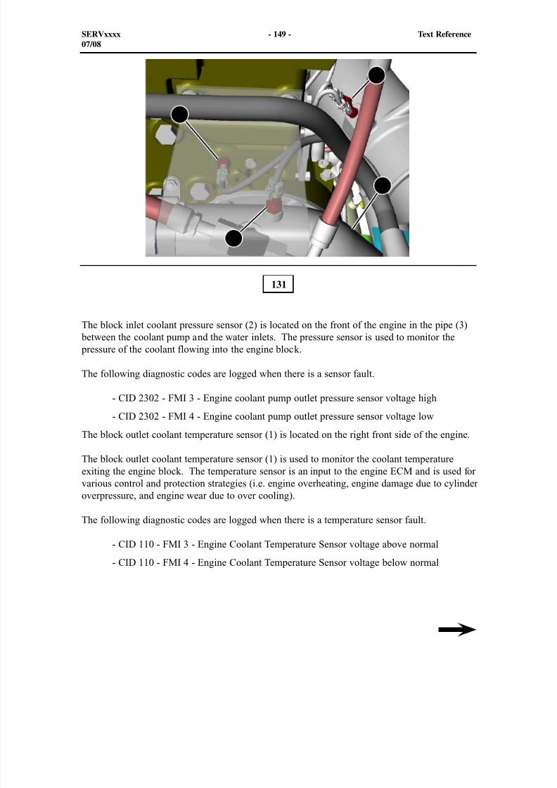
8/9/2019 797F HAA - Meeting Guide.pdf
http://slidepdf.com/reader/full/797f-haa-meeting-guidepdf 164/367

8/9/2019 797F HAA - Meeting Guide.pdf
http://slidepdf.com/reader/full/797f-haa-meeting-guidepdf 165/367
Also, the block outlet coolant temperature sensor initiates the following warning levels.
- E361 Level 1 Warning
- E361 Level 2 Derate
- E361 Level 3 Shutdown
SERVxxxx - 150 - Text Reference07/08
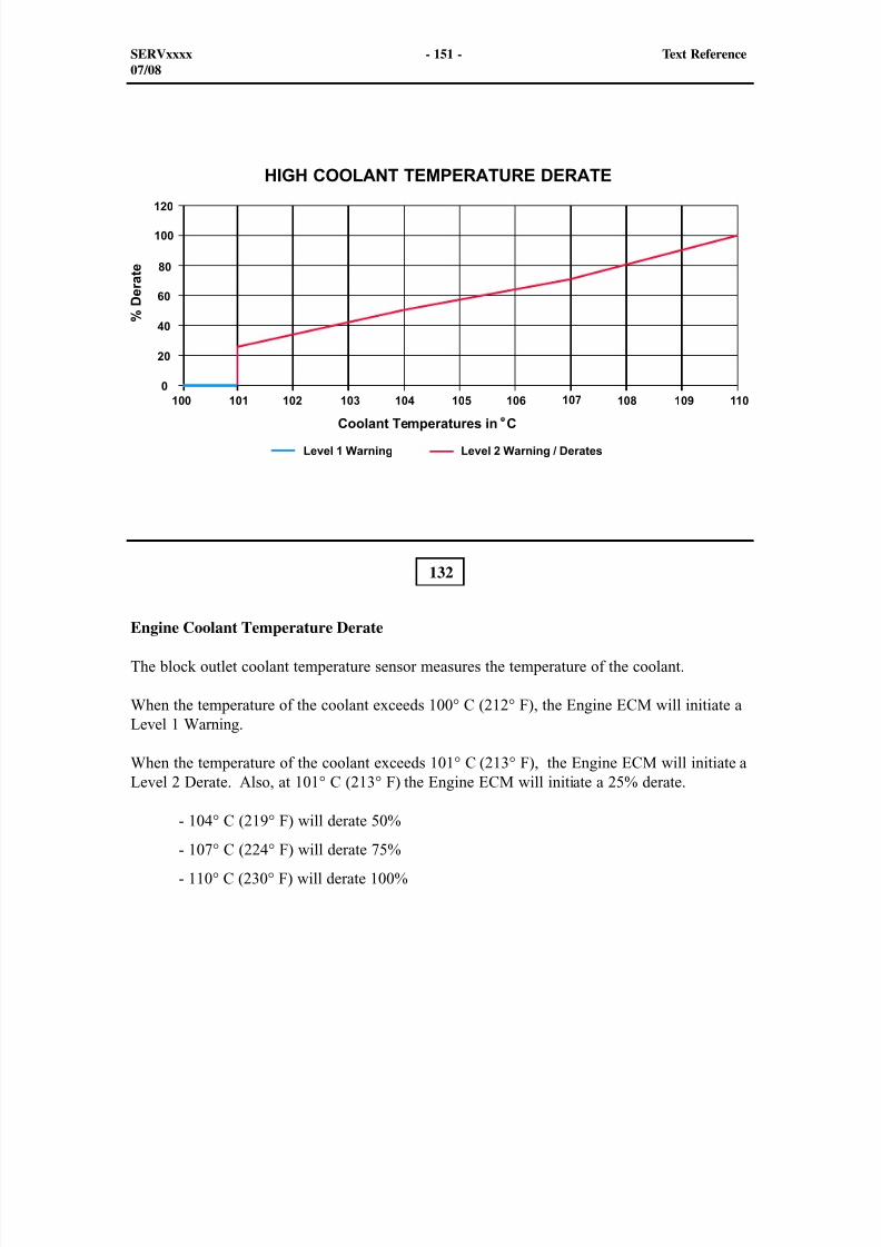
8/9/2019 797F HAA - Meeting Guide.pdf
http://slidepdf.com/reader/full/797f-haa-meeting-guidepdf 166/367
132
Engine Coolant Temperature Derate
The block outlet coolant temperature sensor measures the temperature of the coolant.
When the temperature of the coolant exceeds 100° C (212° F), the Engine ECM will initiate aLevel 1 Warning.
When the temperature of the coolant exceeds 101° C (213° F), the Engine ECM will initiate aLevel 2 Derate. Also, at 101° C (213° F) the Engine ECM will initiate a 25% derate.
- 104° C (219° F) will derate 50%
- 107° C (224° F) will derate 75%
- 110° C (230° F) will derate 100%
SERVxxxx - 151 - Text Reference07/08
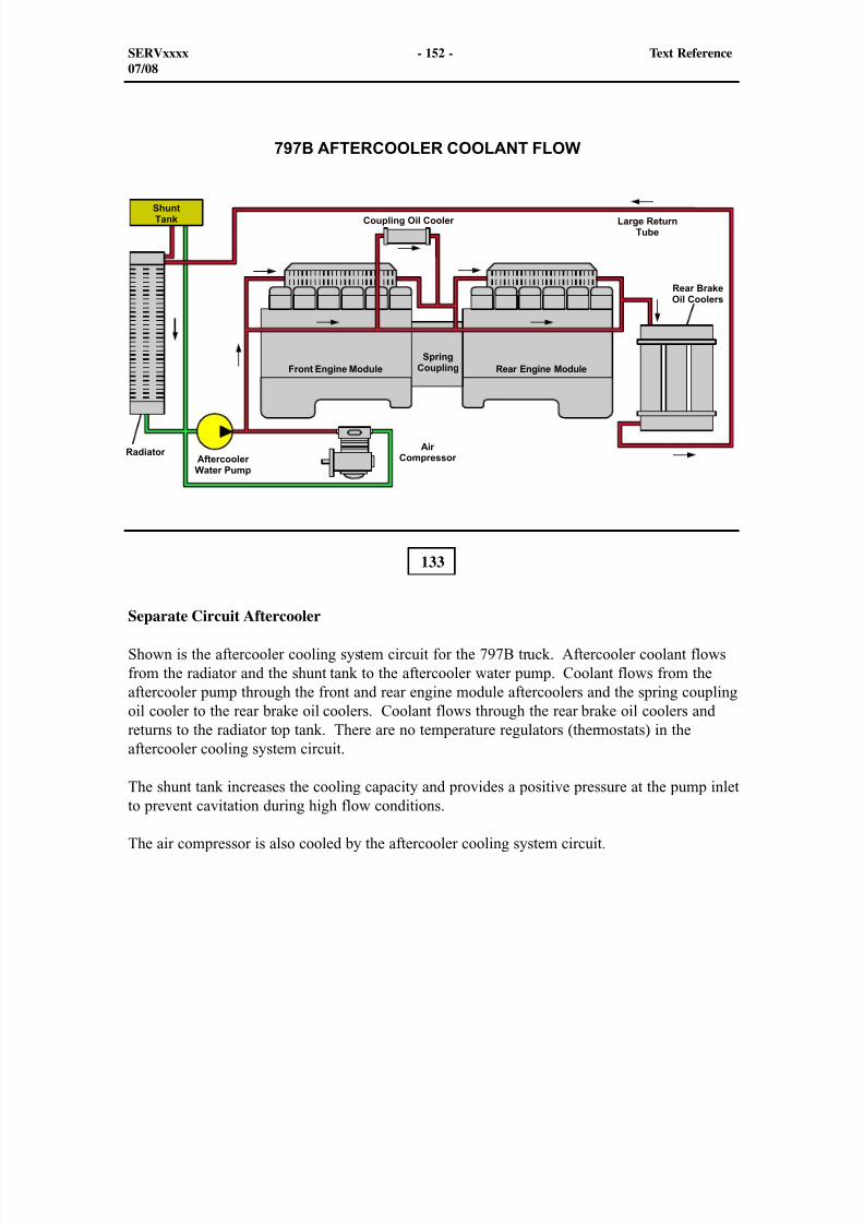
8/9/2019 797F HAA - Meeting Guide.pdf
http://slidepdf.com/reader/full/797f-haa-meeting-guidepdf 167/367
133
Separate Circuit Aftercooler
Shown is the aftercooler cooling system circuit for the 797B truck. Aftercooler coolant flowsfrom the radiator and the shunt tank to the aftercooler water pump. Coolant flows from theaftercooler pump through the front and rear engine module aftercoolers and the spring couplingoil cooler to the rear brake oil coolers. Coolant flows through the rear brake oil coolers andreturns to the radiator top tank. There are no temperature regulators (thermostats) in theaftercooler cooling system circuit.
The shunt tank increases the cooling capacity and provides a positive pressure at the pump inletto prevent cavitation during high flow conditions.
The air compressor is also cooled by the aftercooler cooling system circuit.
SERVxxxx - 152 - Text Reference07/08
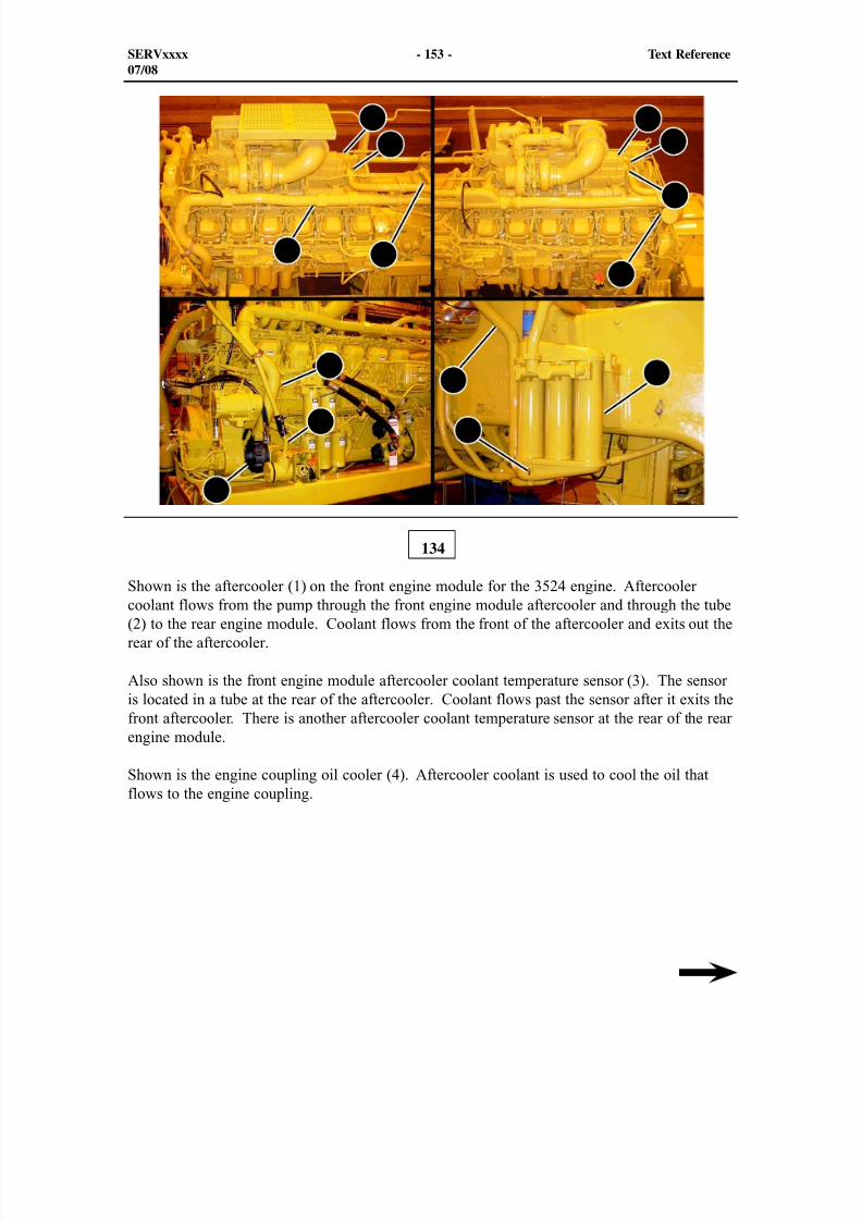
8/9/2019 797F HAA - Meeting Guide.pdf
http://slidepdf.com/reader/full/797f-haa-meeting-guidepdf 168/367
134
SERVxxxx - 153 - Text Reference07/08
Shown is the aftercooler (1) on the front engine module for the 3524 engine. Aftercoolercoolant flows from the pump through the front engine module aftercooler and through the tube(2) to the rear engine module. Coolant flows from the front of the aftercooler and exits out therear of the aftercooler.
Also shown is the front engine module aftercooler coolant temperature sensor (3). The sensoris located in a tube at the rear of the aftercooler. Coolant flows past the sensor after it exits thefront aftercooler. There is another aftercooler coolant temperature sensor at the rear of the rearengine module.
Shown is the engine coupling oil cooler (4). Aftercooler coolant is used to cool the oil that
flows to the engine coupling.
1
2
3
4
5
6
7
8
9
10
11 1213
14
8/9/2019 797F HAA - Meeting Guide.pdf
http://slidepdf.com/reader/full/797f-haa-meeting-guidepdf 169/367
Shown is the aftercooler (5) on the rear engine module. Aftercooler coolant flows from theaftercooler pump through the rear engine module aftercooler and through the tube (6) to therear brake oil coolers. Coolant flows from the front of the aftercooler and exits out the rear ofthe aftercooler.
Shown is the rear engine module aftercooler coolant temperature sensor (7). The sensor islocated in a tube at the rear of the aftercooler. Coolant flows past the sensor after it exits therear aftercooler and before it enters the rear brake oil coolers. There is another aftercoolercoolant temperature sensor at the rear of the front engine module.
Also shown is the rear engine module jacket water coolant temperature sensor (8). The sensoris located in a manifold at the right rear corner of the engine. Typically, the right rear corner ofan engine runs the hottest because it is at the end of the oil and coolant flow path.
The auxiliary (aftercooler) water pump (9) for the aftercooler cooling system is located on
the left side of the front engine module. Coolant enters the aftercooler water pump from theradiator or the shunt tank supply tube (10). Coolant flows from the pump to the aftercoolercores through the large tube (11).
Aftercooler coolant flows from the rear engine module through the rear brake oil coolers (12).Coolant flows from the top of the coolers and exits out the bottom. Aftercooler coolant thenflows through the tube (13) and returns to the radiator top tank.
An S•O•S coolant analysis tap (14) for the aftercooler cooling system is located in the oilcooler bottom tank.
SERVxxxx - 154 - Text Reference07/08
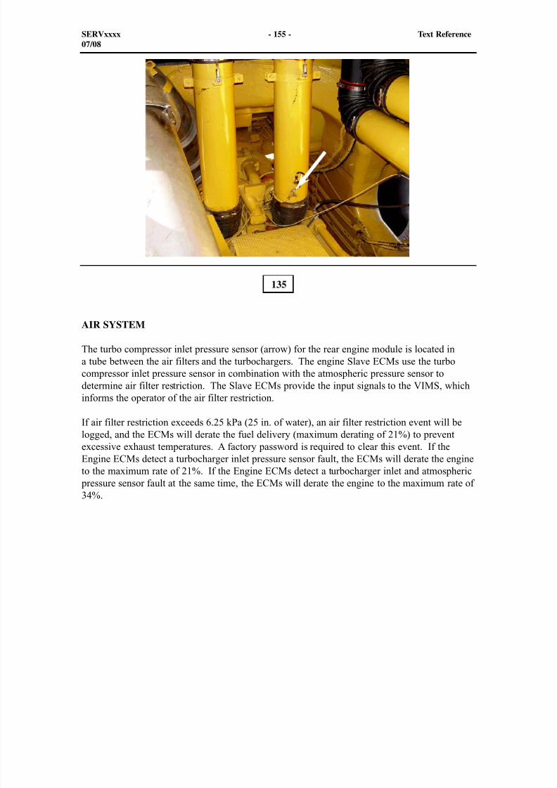
8/9/2019 797F HAA - Meeting Guide.pdf
http://slidepdf.com/reader/full/797f-haa-meeting-guidepdf 170/367
AIR SYSTEM
The turbo compressor inlet pressure sensor (arrow) for the rear engine module is located ina tube between the air filters and the turbochargers. The engine Slave ECMs use the turbocompressor inlet pressure sensor in combination with the atmospheric pressure sensor to
determine air filter restriction. The Slave ECMs provide the input signals to the VIMS, whichinforms the operator of the air filter restriction.
If air filter restriction exceeds 6.25 kPa (25 in. of water), an air filter restriction event will belogged, and the ECMs will derate the fuel delivery (maximum derating of 21%) to preventexcessive exhaust temperatures. A factory password is required to clear this event. If theEngine ECMs detect a turbocharger inlet pressure sensor fault, the ECMs will derate the engineto the maximum rate of 21%. If the Engine ECMs detect a turbocharger inlet and atmospheric
pressure sensor fault at the same time, the ECMs will derate the engine to the maximum rate of34%.
135
SERVxxxx - 155 - Text Reference07/08
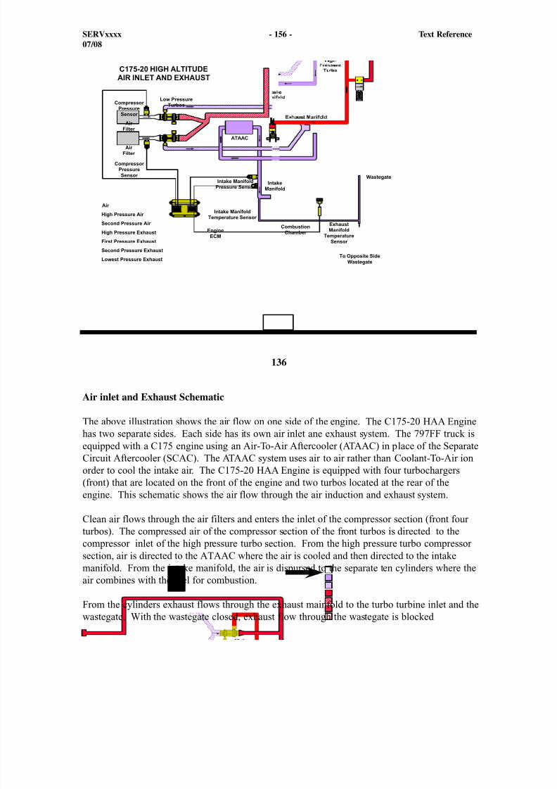
8/9/2019 797F HAA - Meeting Guide.pdf
http://slidepdf.com/reader/full/797f-haa-meeting-guidepdf 171/367
136
Air inlet and Exhaust Schematic
The above illustration shows the air flow on one side of the engine. The C175-20 HAA Enginehas two separate sides. Each side has its own air inlet ane exhaust system. The 797FF truck isequipped with a C175 engine using an Air-To-Air Aftercooler (ATAAC) in place of the SeparateCircuit Aftercooler (SCAC). The ATAAC system uses air to air rather than Coolant-To-Air ionorder to cool the intake air. The C175-20 HAA Engine is equipped with four turbochargers(front) that are located on the front of the engine and two turbos located at the rear of theengine. This schematic shows the air flow through the air induction and exhaust system.
Clean air flows through the air filters and enters the inlet of the compressor section (front fourturbos). The compressed air of the compressor section of the front turbos is directed to thecompressor inlet of the high pressure turbo section. From the high pressure turbo compressorsection, air is directed to the ATAAC where the air is cooled and then directed to the intakemanifold. From the intake manifold, the air is dispursed to the separate ten cylinders where theair combines with the fuel for combustion.
From the cylinders exhaust flows through the exhaust mainfold to the turbo turbine inlet and thewastegate. With the wastegate closed, exhaust flow through the wastegate is blocked
SERVxxxx - 156 - Text Reference07/08
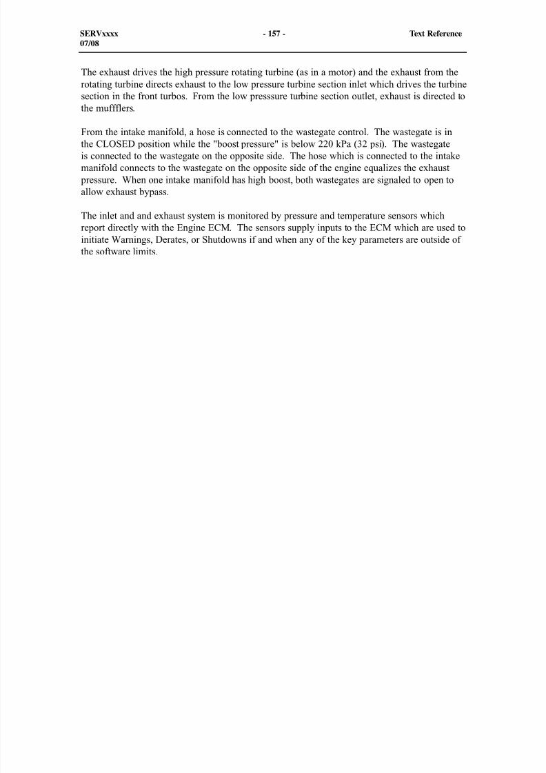
8/9/2019 797F HAA - Meeting Guide.pdf
http://slidepdf.com/reader/full/797f-haa-meeting-guidepdf 172/367
The exhaust drives the high pressure rotating turbine (as in a motor) and the exhaust from therotating turbine directs exhaust to the low pressure turbine section inlet which drives the turbinesection in the front turbos. From the low presssure turbine section outlet, exhaust is directed tothe muffflers.
From the intake manifold, a hose is connected to the wastegate control. The wastegate is inthe CLOSED position while the "boost pressure" is below 220 kPa (32 psi). The wastegateis connected to the wastegate on the opposite side. The hose which is connected to the intakemanifold connects to the wastegate on the opposite side of the engine equalizes the exhaust
pressure. When one intake manifold has high boost, both wastegates are signaled to open toallow exhaust bypass.
The inlet and and exhaust system is monitored by pressure and temperature sensors whichreport directly with the Engine ECM. The sensors supply inputs to the ECM which are used toinitiate Warnings, Derates, or Shutdowns if and when any of the key parameters are outside of
the software limits.
SERVxxxx - 157 - Text Reference07/08
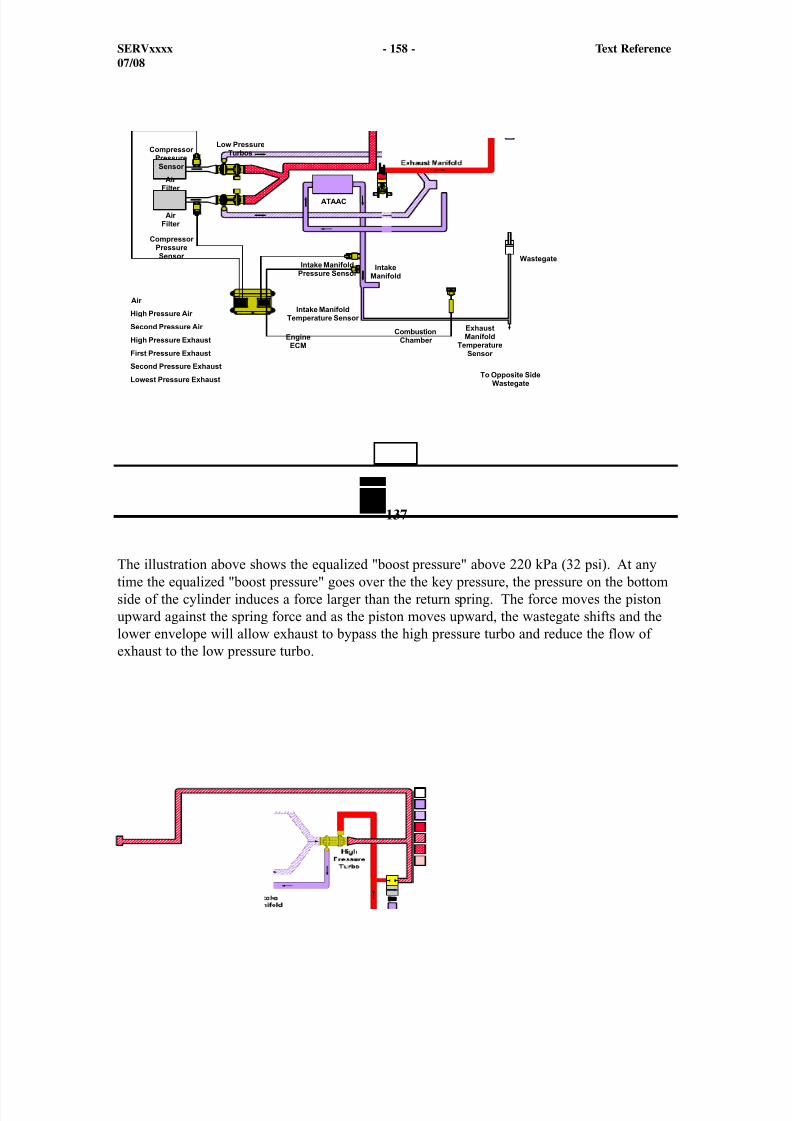
8/9/2019 797F HAA - Meeting Guide.pdf
http://slidepdf.com/reader/full/797f-haa-meeting-guidepdf 173/367
137
The illustration above shows the equalized "boost pressure" above 220 kPa (32 psi). At anytime the equalized "boost pressure" goes over the the key pressure, the pressure on the bottomside of the cylinder induces a force larger than the return spring. The force moves the pistonupward against the spring force and as the piston moves upward, the wastegate shifts and thelower envelope will allow exhaust to bypass the high pressure turbo and reduce the flow ofexhaust to the low pressure turbo.
SERVxxxx - 158 - Text Reference07/08
8/9/2019 797F HAA - Meeting Guide.pdf
http://slidepdf.com/reader/full/797f-haa-meeting-guidepdf 174/367
SERVxxxx - 159 - Text Reference07/08
138
The 797F Truck has an Air-To-Air Aftercooler (ATAAC) which replaces the Separate CircuitAftercooler (SCAC) on the "B" Series truck. The main objective of the ATAAC system is todraw in clean fresh air into the system, cool the air, and send the air into the intake manifold.The air is then directed to the combustion chamber for each cylinder.
Air is drawn into the system through four air cleaner tubes (2), and into the compressor sideof the four low pressure turbos (1). From the discharge of the compressor section, the air issent through tube (3) to the two high pressure turbos (4). From the discharge of the two high
pressure turbos, the air is sent to the top of the ATAACs. The air is transferred through theATAACs where the air is cooled.
1
2
2
2 2
3
43
4
1
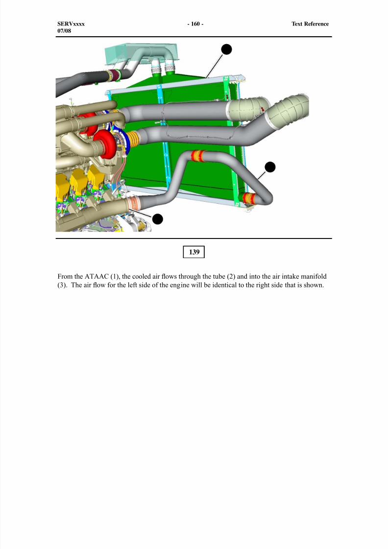
8/9/2019 797F HAA - Meeting Guide.pdf
http://slidepdf.com/reader/full/797f-haa-meeting-guidepdf 175/367
SERVxxxx - 160 - Text Reference07/08
139
From the ATAAC (1), the cooled air ows through the tube (2) and into the air intake manifold(3). The air ow for the left side of the engine will be identical to the right side that is shown.
2
3
1
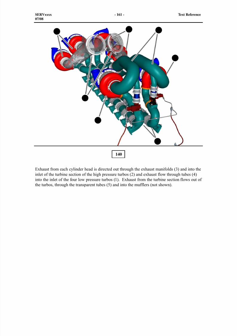
8/9/2019 797F HAA - Meeting Guide.pdf
http://slidepdf.com/reader/full/797f-haa-meeting-guidepdf 176/367
140
Exhaust from each cylinder head is directed out through the exhaust manifolds (3) and into theinlet of the turbine section of the high pressure turbos (2) and exhaust flow through tubes (4)into the inlet of the four low pressure turbos (1). Exhaust from the turbine section flows out ofthe turbos, through the transparent tubes (5) and into the mufflers (not shown).
SERVxxxx - 161 - Text Reference07/08
1
2
2
3
41
5
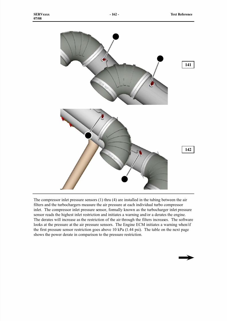
8/9/2019 797F HAA - Meeting Guide.pdf
http://slidepdf.com/reader/full/797f-haa-meeting-guidepdf 177/367
141
142
The compressor inlet pressure sensors (1) thru (4) are installed in the tubing between the airfilters and the turbochargers measure the air pressure at each individual turbo compressor
inlet. The compressor inlet pressure sensor, formally known as the turbocharger inlet pressuresensor reads the highest inlet restriction and initiates a warning and/or a derates the engine.The derates will increase as the restriction of the air through the filters increases. The softwarelooks at the pressure at the air pressure sensors. The Engine ECM initiates a warning when/ifthe first pressure sensor restriction goes above 10 kPa (1.44 psi). The table on the next pageshows the power derate in comparison to the pressure restriction.
SERVxxxx - 162 - Text Reference07/08
1
2
3
4
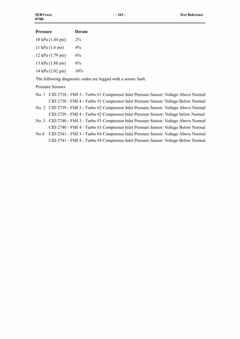
8/9/2019 797F HAA - Meeting Guide.pdf
http://slidepdf.com/reader/full/797f-haa-meeting-guidepdf 178/367
Pressure Derate
10 kPa (1.44 psi) 2%
11 kPa (1.6 psi) 4%
12 kPa (1.79 psi) 6%13 kPa (1.88 psi) 8%
14 kPa (2.02 psi) 10%
The following diagnostic codes are logged with a sensor fault.
Pressure Sensors
No. 1 CID 2738 - FMI 3 - Turbo #1 Compressor Inlet Pressure Sensor: Voltage Above Normal
CID 2738 - FMI 4 - Turbo #1 Compressor Inlet Pressure Sensor: Voltage Below Normal
No. 2 CID 2739 - FMI 3 - Turbo #2 Compressor Inlet Pressure Sensor: Voltage Above Normal
CID 2739 - FMI 4 - Turbo #2 Compressor Inlet Pressure Sensor: Voltage below Normal
No. 3 CID 2740 - FMI 3 - Turbo #3 Compressor Inlet Pressure Sensor: Voltage Above Normal
CID 2740 - FMI 4 - Turbo #3 Compressor Inlet Pressure Sensor: Voltage Below Normal
No.4 CID 2341 - FMI 3 - Turbo #4 Compressor Inlet Pressure Sensor: Voltage Above Normal
CID 2741 - FMI 4 - Turbo #4 Compressor Inlet Pressure Sensor: Voltage Below Normal
SERVxxxx - 163 - Text Reference07/08
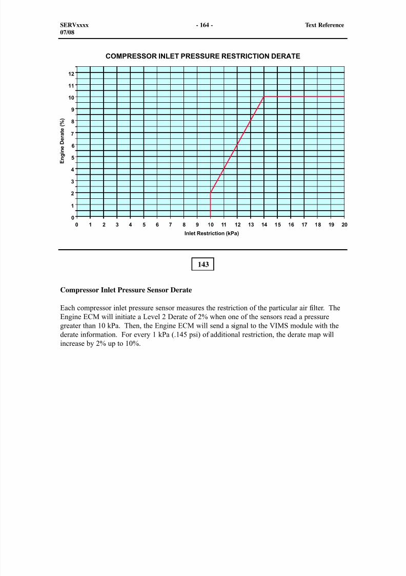
8/9/2019 797F HAA - Meeting Guide.pdf
http://slidepdf.com/reader/full/797f-haa-meeting-guidepdf 179/367
143
Compressor Inlet Pressure Sensor Derate
Each compressor inlet pressure sensor measures the restriction of the particular air filter. TheEngine ECM will initiate a Level 2 Derate of 2% when one of the sensors read a pressuregreater than 10 kPa. Then, the Engine ECM will send a signal to the VIMS module with thederate information. For every 1 kPa (.145 psi) of additional restriction, the derate map willincrease by 2% up to 10%.
SERVxxxx - 164 - Text Reference07/08
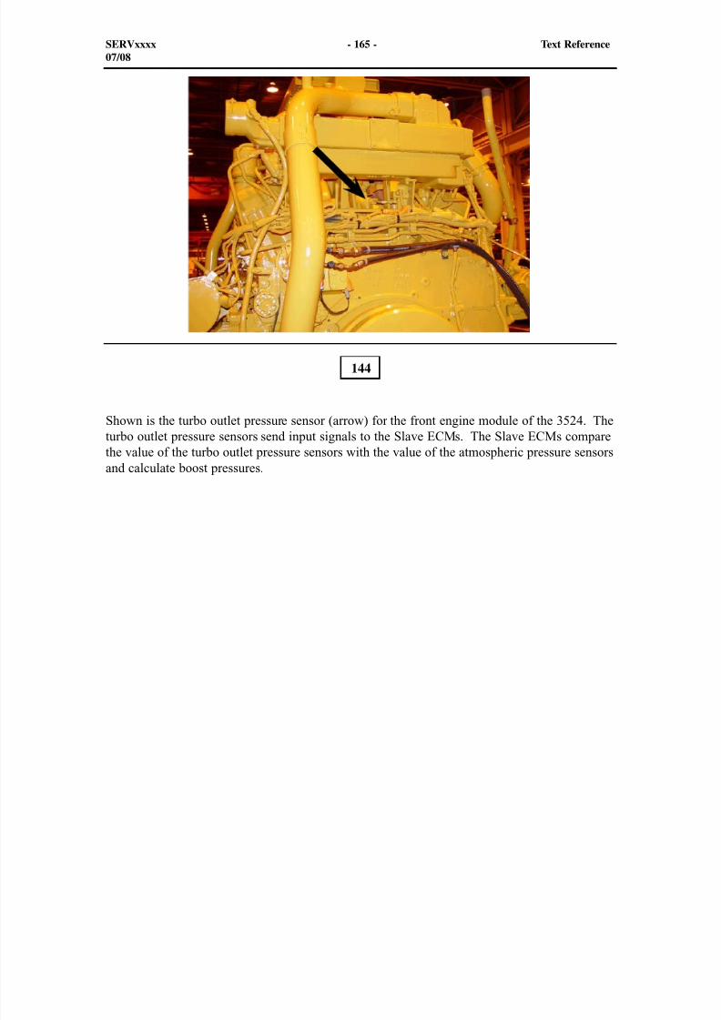
8/9/2019 797F HAA - Meeting Guide.pdf
http://slidepdf.com/reader/full/797f-haa-meeting-guidepdf 180/367
Shown is the turbo outlet pressure sensor (arrow) for the front engine module of the 3524. Theturbo outlet pressure sensors send input signals to the Slave ECMs. The Slave ECMs comparethe value of the turbo outlet pressure sensors with the value of the atmospheric pressure sensorsand calculate boost pressures.
144
SERVxxxx - 165 - Text Reference07/08
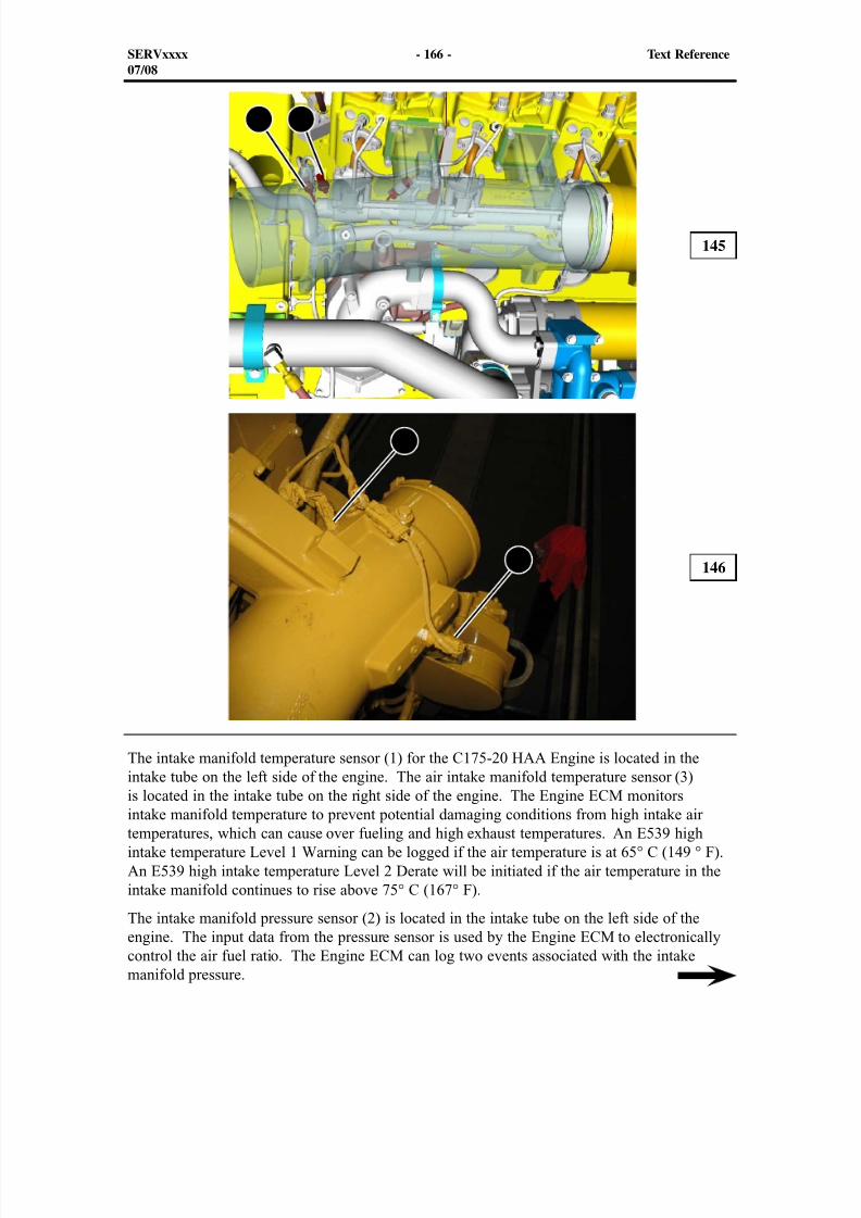
8/9/2019 797F HAA - Meeting Guide.pdf
http://slidepdf.com/reader/full/797f-haa-meeting-guidepdf 181/367
The intake manifold temperature sensor (1) for the C175-20 HAA Engine is located in theintake tube on the left side of the engine. The air intake manifold temperature sensor (3)
is located in the intake tube on the right side of the engine. The Engine ECM monitorsintake manifold temperature to prevent potential damaging conditions from high intake airtemperatures, which can cause over fueling and high exhaust temperatures. An E539 highintake temperature Level 1 Warning can be logged if the air temperature is at 65° C (149 ° F).An E539 high intake temperature Level 2 Derate will be initiated if the air temperature in theintake manifold continues to rise above 75° C (167° F).
The intake manifold pressure sensor (2) is located in the intake tube on the left side of theengine. The input data from the pressure sensor is used by the Engine ECM to electronicallycontrol the air fuel ratio. The Engine ECM can log two events associated with the intakemanifold pressure.
145
146
SERVxxxx - 166 - Text Reference07/08
1 2
3
4
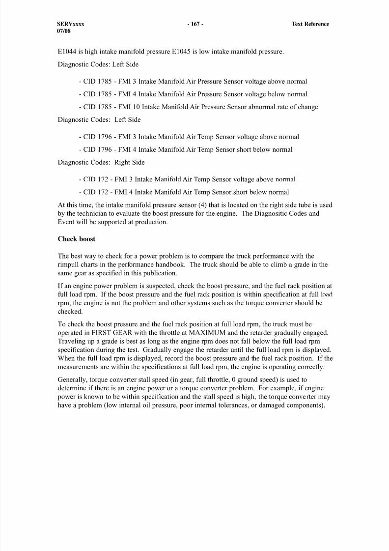
8/9/2019 797F HAA - Meeting Guide.pdf
http://slidepdf.com/reader/full/797f-haa-meeting-guidepdf 182/367
E1044 is high intake manifold pressure E1045 is low intake manifold pressure.
Diagnostic Codes: Left Side
- CID 1785 - FMI 3 Intake Manifold Air Pressure Sensor voltage above normal
- CID 1785 - FMI 4 Intake Manifold Air Pressure Sensor voltage below normal
- CID 1785 - FMI 10 Intake Manifold Air Pressure Sensor abnormal rate of change
Diagnostic Codes: Left Side
- CID 1796 - FMI 3 Intake Manifold Air Temp Sensor voltage above normal
- CID 1796 - FMI 4 Intake Manifold Air Temp Sensor short below normal
Diagnostic Codes: Right Side
- CID 172 - FMI 3 Intake Manifold Air Temp Sensor voltage above normal - CID 172 - FMI 4 Intake Manifold Air Temp Sensor short below normal
At this time, the intake manifold pressure sensor (4) that is located on the right side tube is used by the technician to evaluate the boost pressure for the engine. The Diagnositic Codes andEvent will be supported at production.
Check boost
The best way to check for a power problem is to compare the truck performance with therimpull charts in the performance handbook. The truck should be able to climb a grade in thesame gear as specified in this publication.
If an engine power problem is suspected, check the boost pressure, and the fuel rack position atfull load rpm. If the boost pressure and the fuel rack position is within specification at full loadrpm, the engine is not the problem and other systems such as the torque converter should bechecked.
To check the boost pressure and the fuel rack position at full load rpm, the truck must beoperated in FIRST GEAR with the throttle at MAXIMUM and the retarder gradually engaged.Traveling up a grade is best as long as the engine rpm does not fall below the full load rpmspecification during the test. Gradually engage the retarder until the full load rpm is displayed.
When the full load rpm is displayed, record the boost pressure and the fuel rack position. If themeasurements are within the specifications at full load rpm, the engine is operating correctly.
Generally, torque converter stall speed (in gear, full throttle, 0 ground speed) is used todetermine if there is an engine power or a torque converter problem. For example, if engine
power is known to be within specification and the stall speed is high, the torque converter mayhave a problem (low internal oil pressure, poor internal tolerances, or damaged components).
SERVxxxx - 167 - Text Reference07/08
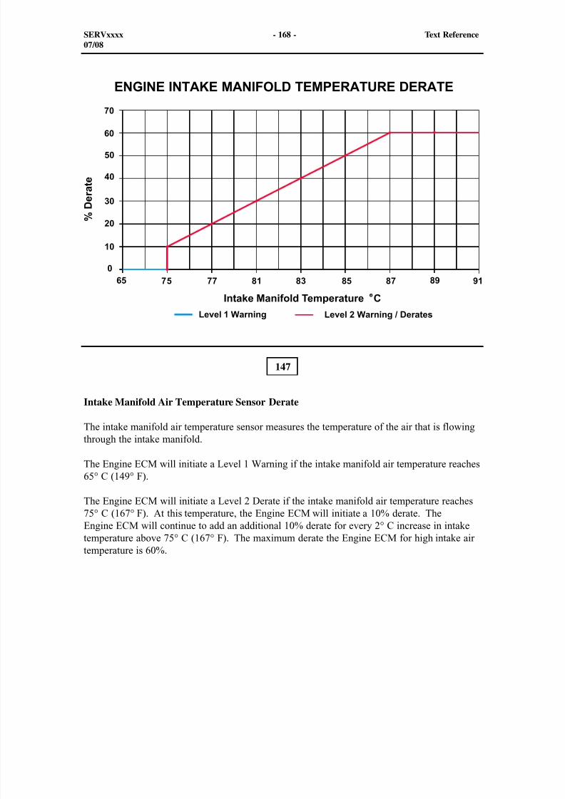
8/9/2019 797F HAA - Meeting Guide.pdf
http://slidepdf.com/reader/full/797f-haa-meeting-guidepdf 183/367
147
Intake Manifold Air Temperature Sensor Derate
The intake manifold air temperature sensor measures the temperature of the air that is flowingthrough the intake manifold.
The Engine ECM will initiate a Level 1 Warning if the intake manifold air temperature reaches65° C (149° F).
The Engine ECM will initiate a Level 2 Derate if the intake manifold air temperature reaches75° C (167° F). At this temperature, the Engine ECM will initiate a 10% derate. TheEngine ECM will continue to add an additional 10% derate for every 2° C increase in intaketemperature above 75° C (167° F). The maximum derate the Engine ECM for high intake airtemperature is 60%.
SERVxxxx - 168 - Text Reference07/08
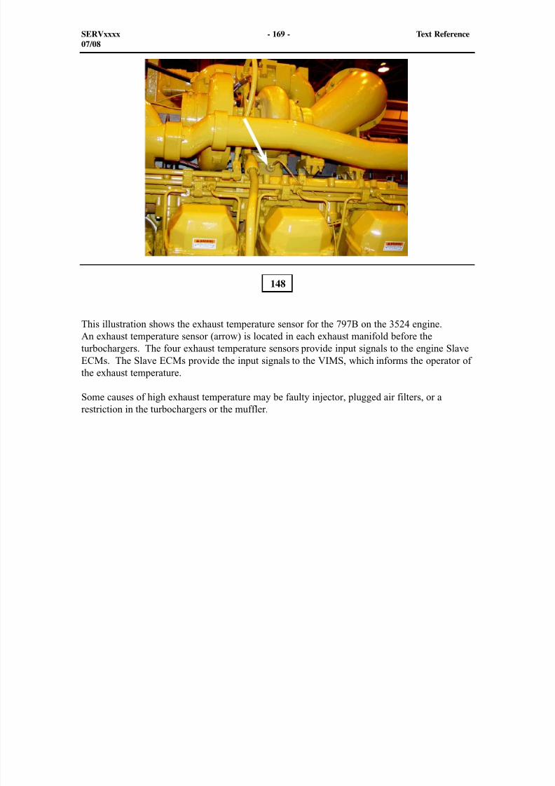
8/9/2019 797F HAA - Meeting Guide.pdf
http://slidepdf.com/reader/full/797f-haa-meeting-guidepdf 184/367
This illustration shows the exhaust temperature sensor for the 797B on the 3524 engine.An exhaust temperature sensor (arrow) is located in each exhaust manifold before theturbochargers. The four exhaust temperature sensors provide input signals to the engine SlaveECMs. The Slave ECMs provide the input signals to the VIMS, which informs the operator ofthe exhaust temperature.
Some causes of high exhaust temperature may be faulty injector, plugged air filters, or arestriction in the turbochargers or the muffler.
148
SERVxxxx - 169 - Text Reference07/08
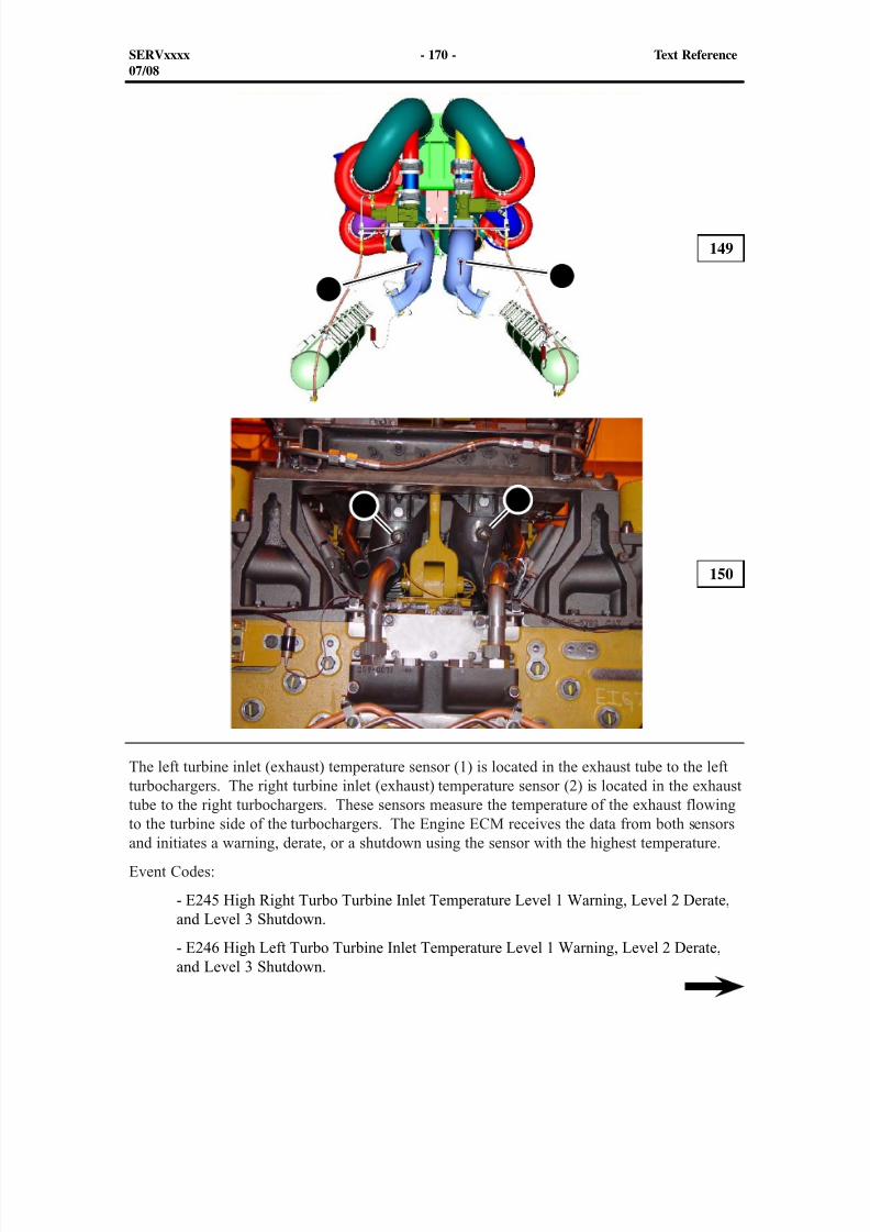
8/9/2019 797F HAA - Meeting Guide.pdf
http://slidepdf.com/reader/full/797f-haa-meeting-guidepdf 185/367
SERVxxxx - 170 - Text Reference07/08
149
150
The left turbine inlet (exhaust) temperature sensor (1) is located in the exhaust tube to the leftturbochargers. The right turbine inlet (exhaust) temperature sensor (2) is located in the exhaust
tube to the right turbochargers. These sensors measure the temperature of the exhaust flowingto the turbine side of the turbochargers. The Engine ECM receives the data from both sensorsand initiates a warning, derate, or a shutdown using the sensor with the highest temperature.
Event Codes:
- E245 High Right Turbo Turbine Inlet Temperature Level 1 Warning, Level 2 Derate,and Level 3 Shutdown.
- E246 High Left Turbo Turbine Inlet Temperature Level 1 Warning, Level 2 Derate,and Level 3 Shutdown.
1 2
21
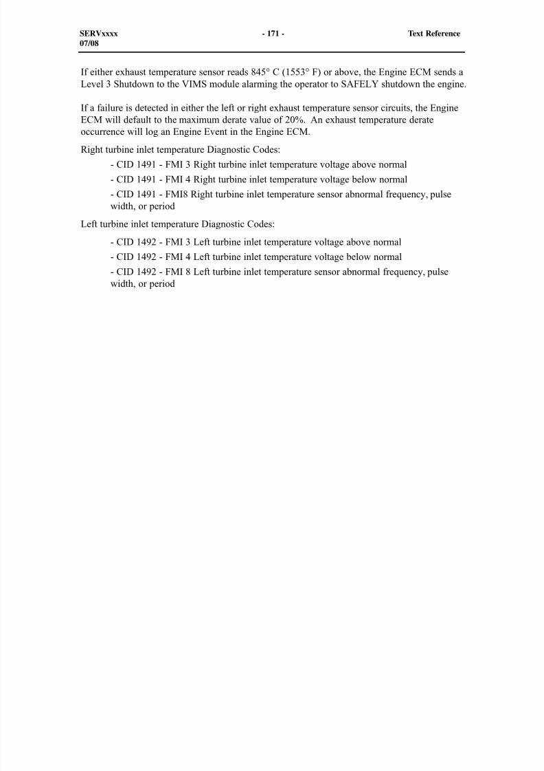
8/9/2019 797F HAA - Meeting Guide.pdf
http://slidepdf.com/reader/full/797f-haa-meeting-guidepdf 186/367
SERVxxxx - 171 - Text Reference07/08
If either exhaust temperature sensor reads 845° C (1553° F) or above, the Engine ECM sends aLevel 3 Shutdown to the VIMS module alarming the operator to SAFELY shutdown the engine.
If a failure is detected in either the left or right exhaust temperature sensor circuits, the EngineECM will default to the maximum derate value of 20%. An exhaust temperature derateoccurrence will log an Engine Event in the Engine ECM.
Right turbine inlet temperature Diagnostic Codes:
- CID 1491 - FMI 3 Right turbine inlet temperature voltage above normal
- CID 1491 - FMI 4 Right turbine inlet temperature voltage below normal
- CID 1491 - FMI8 Right turbine inlet temperature sensor abnormal frequency, pulsewidth, or period
Left turbine inlet temperature Diagnostic Codes:
- CID 1492 - FMI 3 Left turbine inlet temperature voltage above normal
- CID 1492 - FMI 4 Left turbine inlet temperature voltage below normal
- CID 1492 - FMI 8 Left turbine inlet temperature sensor abnormal frequency, pulsewidth, or period
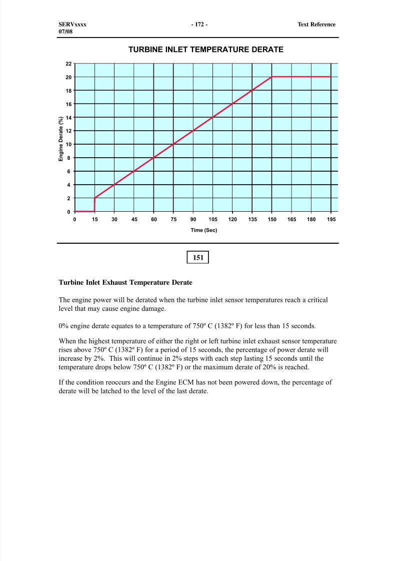
8/9/2019 797F HAA - Meeting Guide.pdf
http://slidepdf.com/reader/full/797f-haa-meeting-guidepdf 187/367
151
Turbine Inlet Exhaust Temperature Derate
The engine power will be derated when the turbine inlet sensor temperatures reach a criticallevel that may cause engine damage.
0% engine derate equates to a temperature of 750º C (1382º F) for less than 15 seconds.
When the highest temperature of either the right or left turbine inlet exhaust sensor temperaturerises above 750º C (1382º F) for a period of 15 seconds, the percentage of power derate willincrease by 2%. This will continue in 2% steps with each step lasting 15 seconds until the
temperature drops below 750º C (1382º F) or the maximum derate of 20% is reached.
If the condition reoccurs and the Engine ECM has not been powered down, the percentage ofderate will be latched to the level of the last derate.
SERVxxxx - 172 - Text Reference07/08
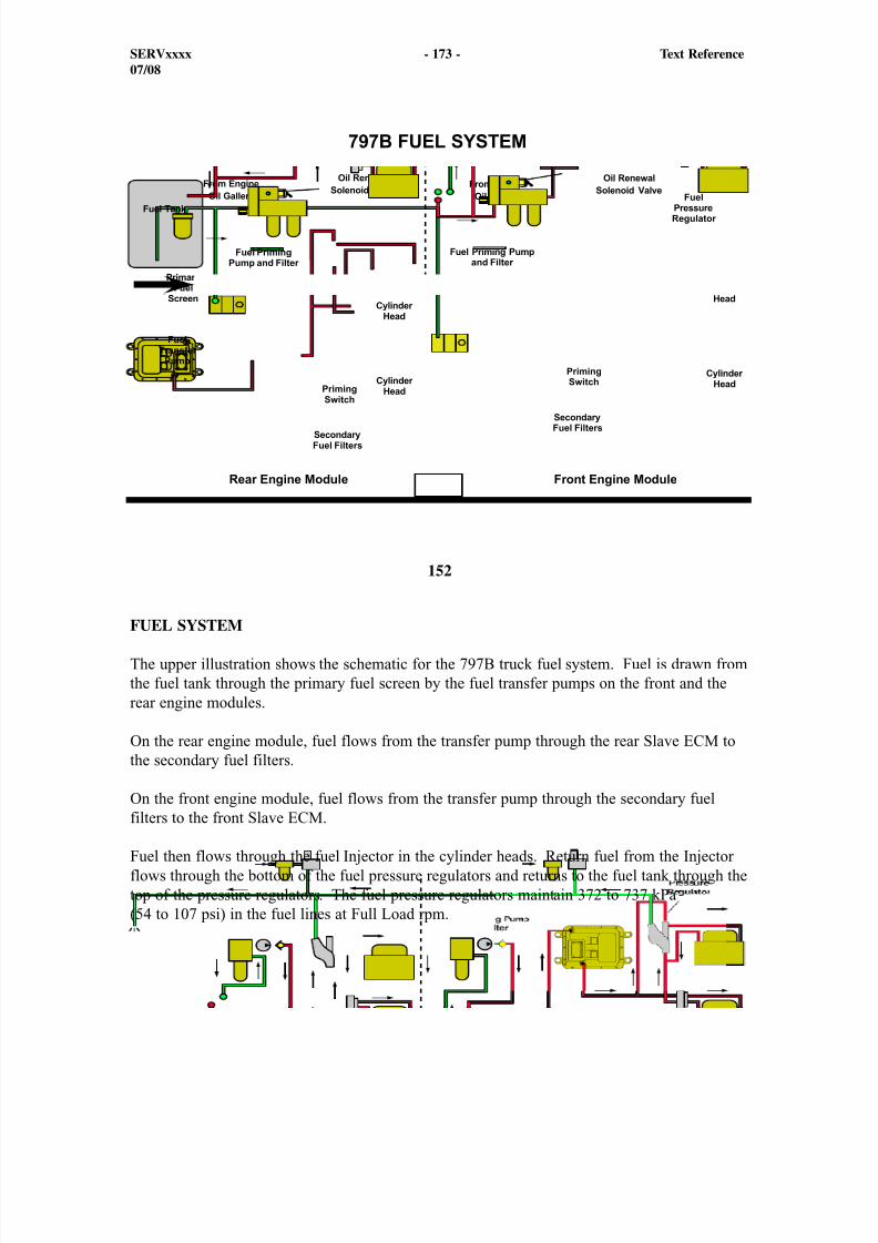
8/9/2019 797F HAA - Meeting Guide.pdf
http://slidepdf.com/reader/full/797f-haa-meeting-guidepdf 188/367
152
FUEL SYSTEM
The upper illustration shows the schematic for the 797B truck fuel system. Fuel is drawn fromthe fuel tank through the primary fuel screen by the fuel transfer pumps on the front and therear engine modules.
On the rear engine module, fuel flows from the transfer pump through the rear Slave ECM tothe secondary fuel filters.
On the front engine module, fuel flows from the transfer pump through the secondary fuelfilters to the front Slave ECM.
Fuel then flows through the fuel Injector in the cylinder heads. Return fuel from the Injectorflows through the bottom of the fuel pressure regulators and returns to the fuel tank through thetop of the pressure regulators. The fuel pressure regulators maintain 372 to 737 kPa(54 to 107 psi) in the fuel lines at Full Load rpm.
SERVxxxx - 173 - Text Reference07/08
8/9/2019 797F HAA - Meeting Guide.pdf
http://slidepdf.com/reader/full/797f-haa-meeting-guidepdf 189/367
If equipped with the attachment engine oil renewal system, engine oil flows from the engine block through an oil filter to the engine oil renewal solenoid valve. When the solenoid isenergized and de-energized, a small amount of oil flows from the engine oil renewal solenoidvalve into the fuel line that returns to the fuel tank. The engine oil returns to the fuel tank withthe return fuel. The engine oil mixes with the fuel in the tank and flows with the fuel to theEUI Injector to be burned.
Two secondary fuel filters are located above the engine oil filters on the left side of thefront and the rear engine modules. Located above the fuel filters is a switch that controlsthe electrical fuel priming pump. A 10 amp circuit breaker protects the fuel priming pumpelectrical circuit. During operation of the electrical fuel priming system, fuel flows from thefuel transfer pump through the fuel priming filter and the check valve to the secondary fuelfilters and the rest of the fuel system. The check valve prevents fuel from flowing backwardsthrough the fuel priming system during normal operation. The main function of the fuel
priming system is to fill the secondary fuel filters after a fuel filter change.
SERVxxxx - 174 - Text Reference07/08
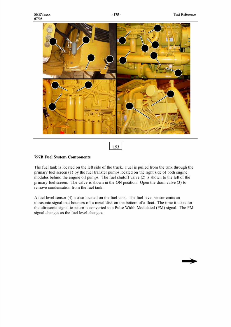
8/9/2019 797F HAA - Meeting Guide.pdf
http://slidepdf.com/reader/full/797f-haa-meeting-guidepdf 190/367
12
3 45
6
7
8
9
1011
1213
14 15
16
153
SERVxxxx - 175 - Text Reference07/08
797B Fuel System Components
The fuel tank is located on the left side of the truck. Fuel is pulled from the tank through the primary fuel screen (1) by the fuel transfer pumps located on the right side of both enginemodules behind the engine oil pumps. The fuel shutoff valve (2) is shown to the left of the
primary fuel screen. The valve is shown in the ON position. Open the drain valve (3) toremove condensation from the fuel tank.
A fuel level sensor (4) is also located on the fuel tank. The fuel level sensor emits anultrasonic signal that bounces off a metal disk on the bottom of a float. The time it takes forthe ultrasonic signal to return is converted to a Pulse Width Modulated (PM) signal. The PM
signal changes as the fuel level changes.
8/9/2019 797F HAA - Meeting Guide.pdf
http://slidepdf.com/reader/full/797f-haa-meeting-guidepdf 191/367
There are two fuel transfer pumps, one on each engine module. The fuel transfer pumps (5)are located behind the engine oil pumps. The fuel transfer pumps contain a bypass valve (6) to
protect the fuel system components from excessive pressure.
Also shown is the fuel priming filter (7) and the electrical fuel priming pump (8). Duringoperation of the electrical fuel priming system, fuel flows from the fuel transfer pump throughthe hose (9), the fuel priming filter, the check valve (10), and the hose (11) to the secondaryfuel filters and the rest of the fuel system. The check valve prevents fuel from flowing
backwards through the fuel priming system during normal operation.
The main function of the fuel priming system is to fill the secondary fuel filters after a fuelfilter change. The fuel priming system can also be used to fill the fuel system with fuel ifthe engine has run out of fuel. If the engine has run out of fuel, the fuel return line must be
blocked during priming in order to force fuel into the Injector.
Fuel only flows through the fuel priming filters when the electrical fuel priming pump isrunning. Generally, the fuel priming filters do not need to be changed through the life of theengine. Service these filters only as needed.
NOTE: If the engine has run out of fuel and the fuel system requires priming, it may benecessary to block the fuel return line during priming to force the fuel into the Injector.
Two secondary fuel filters are located above the engine oil filters on the left side of the frontand the rear engine modules.
Fuel filter restriction is monitored with a fuel filter bypass switch (14) located on the fuel filter base. The fuel filter bypass switches provide input signals to the engine Slave ECMs.
Fuel flows from the fuel filter base through the Electronic Unit Injection (EUI) fuel Injectorand the fuel pressure regulator and then returns to the fuel tank. The Injector receive 4 1/2times the amount of fuel needed for injection. The extra fuel is used for cooling.
Return fuel from the Injector flows through the fuel pressure regulator (16) before returning tothe fuel tank. Fuel pressure is controlled by the fuel pressure regulator.
Fuel pressure should be 372 to 737 kPa (54 to 107 psi) at Full Load rpm.
SERVxxxx - 176 - Text Reference07/08
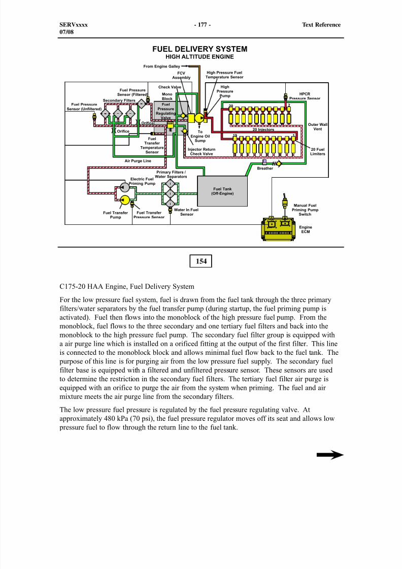
8/9/2019 797F HAA - Meeting Guide.pdf
http://slidepdf.com/reader/full/797f-haa-meeting-guidepdf 192/367
154
C175-20 HAA Engine, Fuel Delivery System
For the low pressure fuel system, fuel is drawn from the fuel tank through the three primaryfilters/water separators by the fuel transfer pump (during startup, the fuel priming pump isactivated). Fuel then flows into the monoblock of the high pressure fuel pump. From themonoblock, fuel flows to the three secondary and one tertiary fuel filters and back into themonoblock to the high pressure fuel pump. The secondary fuel filter group is equipped witha air purge line which is installed on a orificed fitting at the output of the first filter. This lineis connected to the monoblock block and allows minimal fuel flow back to the fuel tank. The
purpose of this line is for purging air from the low pressure fuel supply. The secondary fuel
filter base is equipped with a filtered and unfiltered pressure sensor. These sensors are usedto determine the restriction in the secondary fuel filters. The tertiary fuel filter air purge isequipped with an orifice to purge the air from the system when priming. The fuel and airmixture meets the air purge line from the secondary filters.
The low pressure fuel pressure is regulated by the fuel pressure regulating valve. Atapproximately 480 kPa (70 psi), the fuel pressure regulator moves off its seat and allows low
pressure fuel to flow through the return line to the fuel tank.
SERVxxxx - 177 - Text Reference07/08
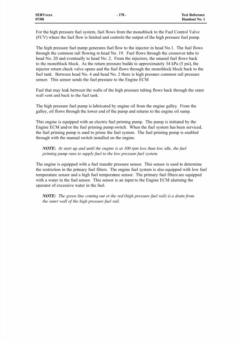
8/9/2019 797F HAA - Meeting Guide.pdf
http://slidepdf.com/reader/full/797f-haa-meeting-guidepdf 193/367
For the high pressure fuel system, fuel flows from the monoblock to the Fuel Control Valve(FCV) where the fuel flow is limited and controls the output of the high pressure fuel pump.
The high pressure fuel pump generates fuel flow to the injector in head No.1. The fuel flowsthrough the common rail flowing to head No. 19. Fuel flows through the crossover tube tohead No. 20 and eventually to head No. 2. From the injectors, the unused fuel flows backto the monoblock block. As the return pressure builds to approximately 34 kPa (5 psi), theinjector return check valve opens and the fuel flows through the monoblock block back to thefuel tank. Between head No. 4 and head No. 2 there is high pressure common rail pressuresensor. This sensor sends the fuel pressure to the Engine ECM
Fuel that may leak between the walls of the high pressure tubing flows back through the outerwall vent and back to the fuel tank.
The high pressure fuel pump is lubricated by engine oil from the engine galley. From the
galley, oil flows through the lower end of the pump and returns to the engine oil sump.
This engine is equipped with an electric fuel priming pump. The pump is initiated by theEngine ECM and/or the fuel priming pump switch. When the fuel system has been serviced,the fuel priming pump is used to prime the fuel system. The fuel priming pump is enabledthrough with the manual switch installed on the engine.
NOTE: At start up and until the engine is at 100 rpm less than low idle, the fuel priming pump runs to supply fuel to the low pressure fuel system.
The engine is equipped with a fuel transfer pressure sensor. This sensor is used to determinethe restriction in the primary fuel filters. The engine fuel system is also equipped with low fueltemperature sensor and a high fuel temperature sensor. The primary fuel filters are equippedwith a water in the fuel sensor. This sensor is an input to the Engine ECM alarming theoperator of excessive water in the fuel.
NOTE: The green line coming out ot the red (high pressure fuel rail) is a drain fromthe outer wall of the high pressure fuel rail.
SERVxxxx - 178 - Text Reference07/08 Handout No. 1
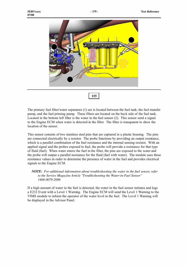
8/9/2019 797F HAA - Meeting Guide.pdf
http://slidepdf.com/reader/full/797f-haa-meeting-guidepdf 194/367
The primary fuel filter/water separators (1) are is located between the fuel tank, the fuel transfer pump, and the fuel priming pump. These filters are located on the back side of the fuel tank.Located in the bottom left filter is the water in the fuel sensor (2). This sensor send a signalto the Engine ECM when water is detected in the filter. The filter is transparent to show thelocation of the sensor.
This sensor consists of two stainless steel pins that are captured in a plastic housing. The pinsare connected electrically by a resistor. The probe functions by providing an output resistance,which is a parallel combination of the fuel resistance and the internal sensing resistor. With anapplied signal and the probes exposed to fuel, the probe will provide a resistance for that typeof fluid (fuel). When water enters the fuel in the filter, the pins are exposed to the water andthe probe will output a parallel resistance for the fluid (fuel with water). The module uses theseresistance values in order to determine the presence of water in the fuel and provides electricalsignals to the Engine ECM.
NOTE: For additional information about troubleshooting the water in the fuel sensor, referto the Service Magazine Article "Troubleshooting the Water-in-Fuel Sensor"1400-0079-2006
If a high amount of water in the fuel is detected, the water in the fuel sensor initiates and logsa E232 Event with a Level 1 Warning. The Engine ECM will send the Level 1 Warning to theVIMS module to inform the operator of the water level in the fuel. The Level 1 Warning will
be displayed in the Advisor Panel.
155
SERVxxxx - 179 - Text Reference07/08
1
1
2
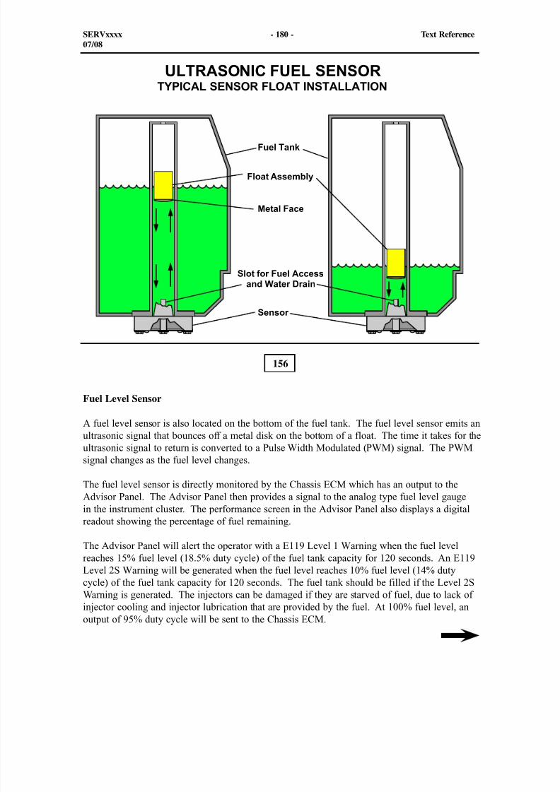
8/9/2019 797F HAA - Meeting Guide.pdf
http://slidepdf.com/reader/full/797f-haa-meeting-guidepdf 195/367
156
Fuel Level Sensor
A fuel level sensor is also located on the bottom of the fuel tank. The fuel level sensor emits anultrasonic signal that bounces off a metal disk on the bottom of a float. The time it takes for theultrasonic signal to return is converted to a Pulse Width Modulated (PWM) signal. The PWMsignal changes as the fuel level changes.
The fuel level sensor is directly monitored by the Chassis ECM which has an output to theAdvisor Panel. The Advisor Panel then provides a signal to the analog type fuel level gaugein the instrument cluster. The performance screen in the Advisor Panel also displays a digitalreadout showing the percentage of fuel remaining.
The Advisor Panel will alert the operator with a E119 Level 1 Warning when the fuel levelreaches 15% fuel level (18.5% duty cycle) of the fuel tank capacity for 120 seconds. An E119Level 2S Warning will be generated when the fuel level reaches 10% fuel level (14% dutycycle) of the fuel tank capacity for 120 seconds. The fuel tank should be filled if the Level 2SWarning is generated. The injectors can be damaged if they are starved of fuel, due to lack ofinjector cooling and injector lubrication that are provided by the fuel. At 100% fuel level, anoutput of 95% duty cycle will be sent to the Chassis ECM.
SERVxxxx - 180 - Text Reference07/08
8/9/2019 797F HAA - Meeting Guide.pdf
http://slidepdf.com/reader/full/797f-haa-meeting-guidepdf 196/367
The following is a list of the Diagnostic Codes for the fuel level sensor. MID 116 - ChassisECM
CID 096 - FMI 03 - Fuel Level Sensor- voltage above normal
CID 096 - FMI 04 - Fuel Level Sensor- voltage below normal
CID 096 - FMI 08 - Fuel Level Sensor- abnormal frequency, pulse width or period
The fuel level sensor receives 24 Volts from chassis power. To check the supply voltage of thesensor, connect a multimeter between Pins 1 and 2 of the sensor connector. Set the meter toread “DC Volts.”
The fuel level sensor output signal is a Pulse Width Modulated (PWM) signal that varies withthe fuel level. To check the output signal of the fuel level sensor, connect a multimeter betweenPins 2 and 4 of the fuel level sensor connector. Set the meter to read “Duty Cycle.” The dutycycle output of the fuel level sensor should be approximately 5% at 0 mm (0 in.) of fuel depth
and 95% at a full fuel depth.
SERVxxxx - 181 - Text Reference07/08
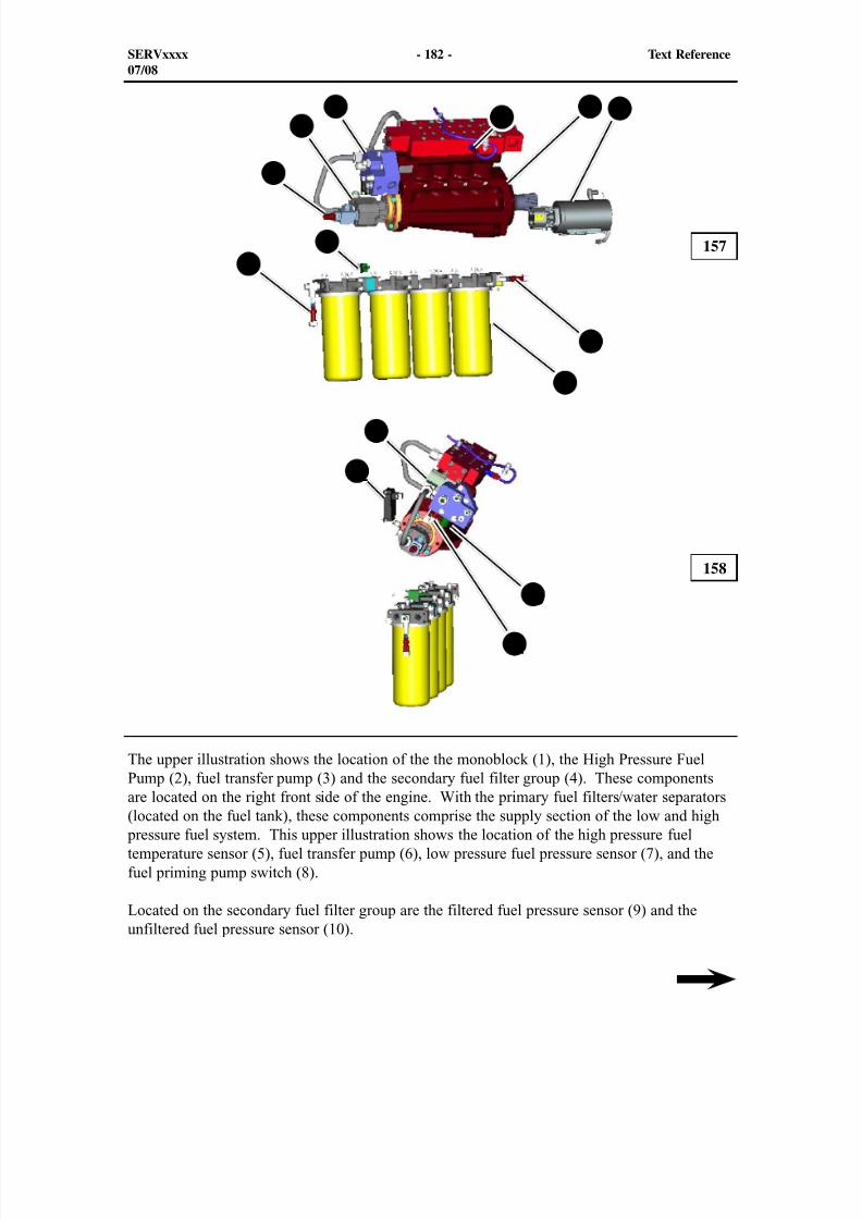
8/9/2019 797F HAA - Meeting Guide.pdf
http://slidepdf.com/reader/full/797f-haa-meeting-guidepdf 197/367
157
158
The upper illustration shows the location of the the monoblock (1), the High Pressure FuelPump (2), fuel transfer pump (3) and the secondary fuel filter group (4). These components
are located on the right front side of the engine. With the primary fuel filters/water separators(located on the fuel tank), these components comprise the supply section of the low and high pressure fuel system. This upper illustration shows the location of the high pressure fueltemperature sensor (5), fuel transfer pump (6), low pressure fuel pressure sensor (7), and thefuel priming pump switch (8).
Located on the secondary fuel filter group are the filtered fuel pressure sensor (9) and theunfiltered fuel pressure sensor (10).
SERVxxxx - 182 - Text Reference07/08
9
4
10
8
35
7
6
12
11
13
14
1 2
8/9/2019 797F HAA - Meeting Guide.pdf
http://slidepdf.com/reader/full/797f-haa-meeting-guidepdf 198/367
The lower illustration shows the location of the fuel control valve (FCV) (11), the suppressionmodule (12), the fuel regulating valve (mono block) (13), and the low fuel pressure systemtemperature sensor (14).
The High Pressure fuel pump suppression module (8) is an inline power module that is locatedon the front right side of the engine. The module is used to keep battery voltage at a steadystate and eliminate voltage spikes.
The suppression module takes an input voltage between 18 and 32 VDC at 1.5 Amps andconverts the voltage to 14 ± 1 VDC. Also, the suppression module is equipped with reverse
polarity protection.
If the power to the FCV is not in specification, ensure the suppression module is connected.This module acts as a buffer for the power supply between FCV and Engine ECM.
The high pressure fuel temperature sensor is located in the cylinder head attached to the topof the high pressure fuel pump. The fuel temperature is measured to ensure that the hightemperature does not exceed the maximum allowable temperature for injector cooling andlubrication.
The Engine ECM can predict the fuel temperature at each fuel injector by using the high pressure fuel temperature sensor measurements along with the fuel rail pressure sensor and theengine coolant temperature sensor.
The following diagnostic codes are logged when there is a sensor fault.
- CID 2323 - FMI 3 - Fuel Rail Temperature Sensor High - voltage above normal
- CID 2323 - FMI 4 - Fuel Rail Temperature Sensor Low - voltage below normal
The temperature sensor can also trip a 770 Event initiating a high fuel rail temperature Level 2Derate. When the fuel temperature in the common rail is at 100 ° C (212° F) or above for a 15seconds duration. The Engine ECM will initiate a Level 2 Derate. The engine will derate 20%under load. When the fuel temperature goes above 101 ° C (214° F) or above for a 15 secondsduration, the engine will derate 40% under load. When the fuel temperature goes above 102 °C (215° F) or above for a 15 seconds duration, the engine will derate 60% under load. Whenthe fuel temperature goes above 103 ° C (217° F) or above for a 15 seconds duration, the
engine will derate 80% under load. When the fuel temperature goes above 104 ° C (219° F)or above for a 15 seconds duration, the engine will derate 100% under load. The followingdiagnostic codes are logged when there is a fuel pressure sensor (unfiltered) fault.
- CID 0289 - FMI 3 - Unfiltered fuel pressure sensor - open/short to +batt
- CID 0289 - FMI 4 - Unfiltered fuel pressure sensor - short to ground
The following diagnostic codes are logged when there is a fuel pressure sensor (filtered) fault.
- CID 0460 - FMI 3 - Filtered fuel pressure sensor - open/short to +batt
- CID 0460 - FMI 4 - Filtered fuel pressure sensor - short to ground
SERVxxxx - 183 - Text Reference07/08
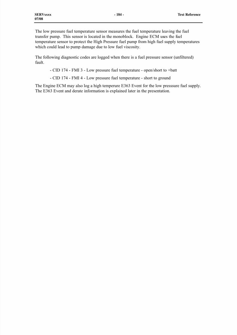
8/9/2019 797F HAA - Meeting Guide.pdf
http://slidepdf.com/reader/full/797f-haa-meeting-guidepdf 199/367
The low pressure fuel temperature sensor measures the fuel temperature leaving the fueltransfer pump. This sensor is located in the monoblock. Engine ECM uses the fueltemperature sensor to protect the High Pressure fuel pump from high fuel supply temperatureswhich could lead to pump damage due to low fuel viscosity.
The following diagnostic codes are logged when there is a fuel pressure sensor (unfiltered)fault.
- CID 174 - FMI 3 - Low pressure fuel temperature - open/short to +batt
- CID 174 - FMI 4 - Low pressure fuel temperature - short to ground
The Engine ECM may also log a high temperure E363 Event for the low presssure fuel supply.The E363 Event and derate information is explained later in the presentation.
SERVxxxx - 184 - Text Reference07/08
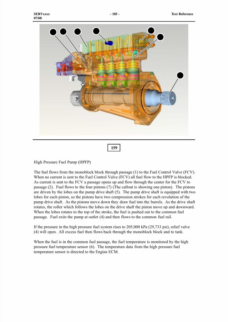
8/9/2019 797F HAA - Meeting Guide.pdf
http://slidepdf.com/reader/full/797f-haa-meeting-guidepdf 200/367
SERVxxxx - 185 - Text Reference07/08
159
High Pressure Fuel Pump (HPFP)
The fuel flows from the monoblock block through passage (1) to the Fuel Control Valve (FCV).When no current is sent to the Fuel Control Valve (FCV) all fuel flow to the HPFP is blocked.As current is sent to the FCV a passage opens up and flow through the center for the FCV to
passage (2). Fuel flows to the four pistons (7) (The callout is showing one piston). The pistonsare driven by the lobes on the pump drive shaft (5). The pump drive shaft is equipped with twolobes for each piston, so the pistons have two compression strokes for each revolution of the
pump drive shaft. As the pistons move down they draw fuel into the barrels. As the drive shaftrotates, the roller which follows the lobes on the drive shaft the piston move up and downward.When the lobes rotates to the top of the stroke, the fuel is pushed out to the common fuel
passage. Fuel exits the pump at outlet (4) and then flows to the common fuel rail.
If the pressure in the high pressure fuel system rises to 205,000 kPa (29,733 psi), relief valve(4) will open. All excess fuel then flows back through the monoblock block and to tank.
When the fuel is in the common fuel passage, the fuel temperature is monitored by the high pressure fuel temperature sensor (6). The temperature data from the high pressure fueltemperature sensor is directed to the Engine ECM.
21 3 4
5
67
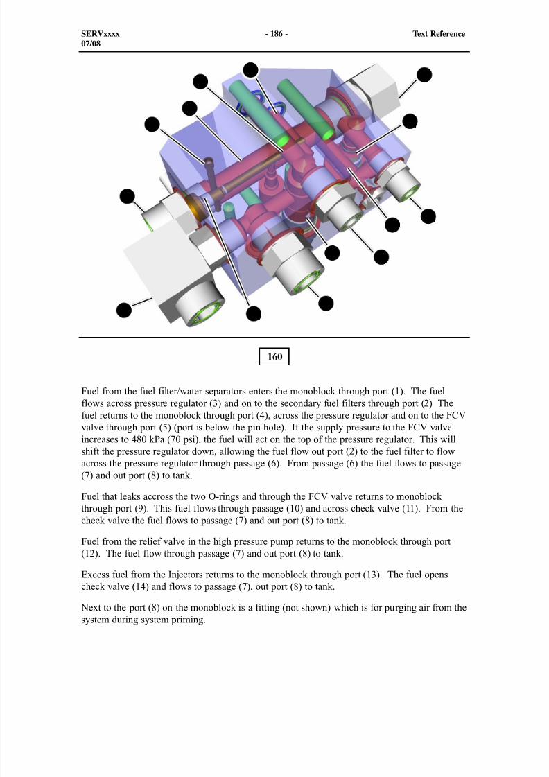
8/9/2019 797F HAA - Meeting Guide.pdf
http://slidepdf.com/reader/full/797f-haa-meeting-guidepdf 201/367
SERVxxxx - 186 - Text Reference07/08
160
Fuel from the fuel filter/water separators enters the monoblock through port (1). The fuelflows across pressure regulator (3) and on to the secondary fuel filters through port (2) Thefuel returns to the monoblock through port (4), across the pressure regulator and on to the FCVvalve through port (5) (port is below the pin hole). If the supply pressure to the FCV valveincreases to 480 kPa (70 psi), the fuel will act on the top of the pressure regulator. This willshift the pressure regulator down, allowing the fuel flow out port (2) to the fuel filter to flowacross the pressure regulator through passage (6). From passage (6) the fuel flows to passage(7) and out port (8) to tank.
Fuel that leaks accross the two O-rings and through the FCV valve returns to monoblock
through port (9). This fuel flows through passage (10) and across check valve (11). From thecheck valve the fuel flows to passage (7) and out port (8) to tank.
Fuel from the relief valve in the high pressure pump returns to the monoblock through port(12). The fuel flow through passage (7) and out port (8) to tank.
Excess fuel from the Injectors returns to the monoblock through port (13). The fuel openscheck valve (14) and flows to passage (7), out port (8) to tank.
Next to the port (8) on the monoblock is a fitting (not shown) which is for purging air from thesystem during system priming.
1 2
3
6
4
95
7
10
11
12
13
8
14
8/9/2019 797F HAA - Meeting Guide.pdf
http://slidepdf.com/reader/full/797f-haa-meeting-guidepdf 202/367
161
The fuel Control Valve consists of tow sections: the control motor (3) and the fuel valve (1).Callout 2 points out pin 1 in the connector. Following the pins downward are 1 thru 6 and
starting upward on the other side are 7 through 12.
The lower illustration shows the valve section in the OPEN position. During the operation inthe high pressure common rail pump, the control fuel flows to the land with the square opening(left side) (4). When the FCV is commanded to increase the precise flow of the high pressure
pump, the inner spool rotates upward. The triangle shaped throttling valve (opening) rotatesupward. As the inner spool moves upward, more opening shows within the square directingadditional flow signal to the high pressure pump. The fuel then flows through the centersection to port (5).
SERVxxxx - 187 - Text Reference07/08
162
21
4 5
3
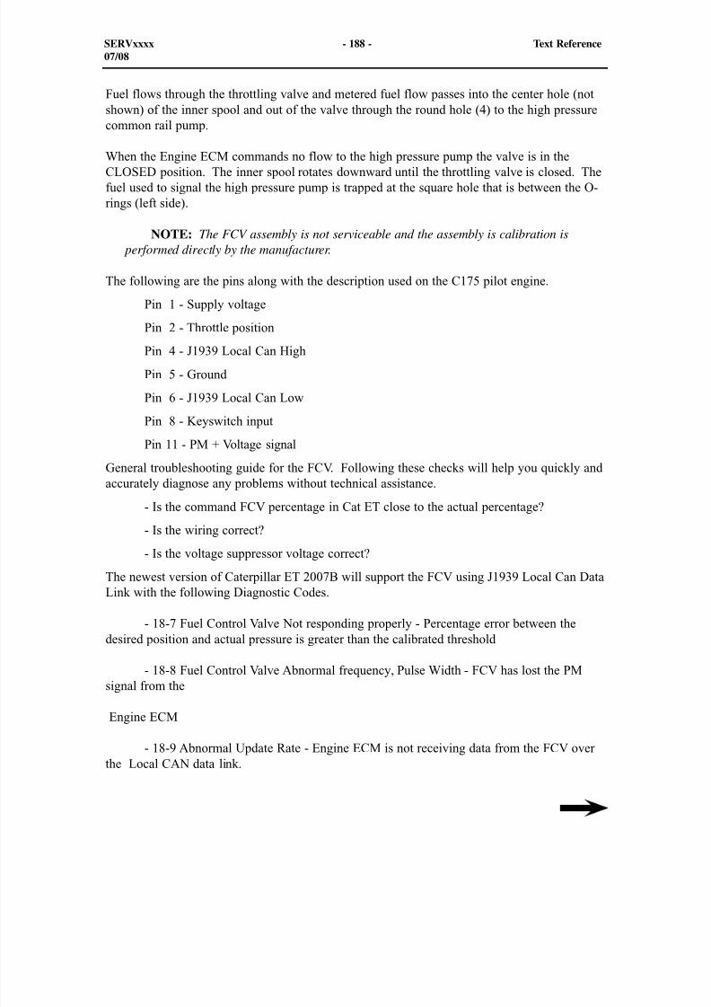
8/9/2019 797F HAA - Meeting Guide.pdf
http://slidepdf.com/reader/full/797f-haa-meeting-guidepdf 203/367
SERVxxxx - 188 - Text Reference07/08
Fuel flows through the throttling valve and metered fuel flow passes into the center hole (notshown) of the inner spool and out of the valve through the round hole (4) to the high pressurecommon rail pump.
When the Engine ECM commands no flow to the high pressure pump the valve is in theCLOSED position. The inner spool rotates downward until the throttling valve is closed. Thefuel used to signal the high pressure pump is trapped at the square hole that is between the O-rings (left side).
NOTE: The FCV assembly is not serviceable and the assembly is calibration is performed directly by the manufacturer.
The following are the pins along with the description used on the C175 pilot engine.
Pin 1 - Supply voltage
Pin 2 - Throttle position Pin 4 - J1939 Local Can High
Pin 5 - Ground
Pin 6 - J1939 Local Can Low
Pin 8 - Keyswitch input
Pin 11 - PM + Voltage signal
General troubleshooting guide for the FCV. Following these checks will help you quickly andaccurately diagnose any problems without technical assistance.
- Is the command FCV percentage in Cat ET close to the actual percentage?
- Is the wiring correct?
- Is the voltage suppressor voltage correct?
The newest version of Caterpillar ET 2007B will support the FCV using J1939 Local Can DataLink with the following Diagnostic Codes.
- 18-7 Fuel Control Valve Not responding properly - Percentage error between thedesired position and actual pressure is greater than the calibrated threshold
- 18-8 Fuel Control Valve Abnormal frequency, Pulse Width - FCV has lost the PMsignal from the
Engine ECM
- 18-9 Abnormal Update Rate - Engine ECM is not receiving data from the FCV overthe Local CAN data link.
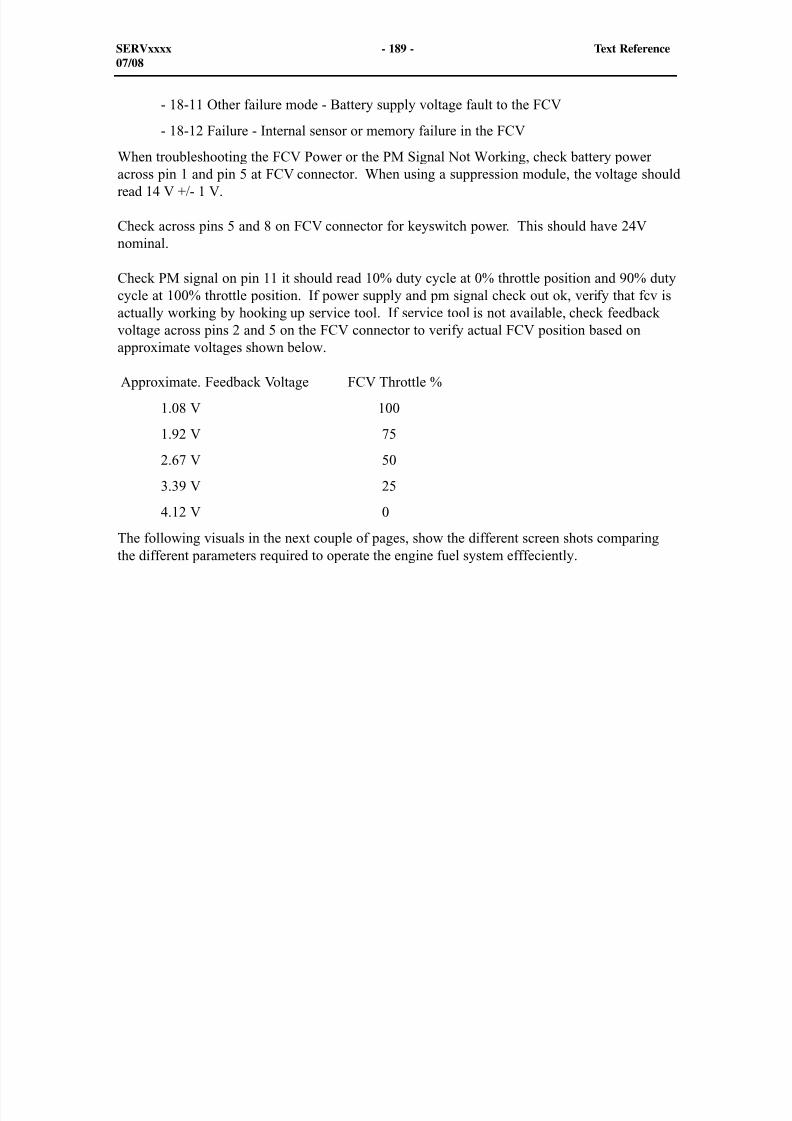
8/9/2019 797F HAA - Meeting Guide.pdf
http://slidepdf.com/reader/full/797f-haa-meeting-guidepdf 204/367
SERVxxxx - 189 - Text Reference07/08
- 18-11 Other failure mode - Battery supply voltage fault to the FCV
- 18-12 Failure - Internal sensor or memory failure in the FCV
When troubleshooting the FCV Power or the PM Signal Not Working, check battery poweracross pin 1 and pin 5 at FCV connector. When using a suppression module, the voltage shouldread 14 V +/- 1 V.
Check across pins 5 and 8 on FCV connector for keyswitch power. This should have 24Vnominal.
Check PM signal on pin 11 it should read 10% duty cycle at 0% throttle position and 90% dutycycle at 100% throttle position. If power supply and pm signal check out ok, verify that fcv isactually working by hooking up service tool. If service tool is not available, check feedbackvoltage across pins 2 and 5 on the FCV connector to verify actual FCV position based onapproximate voltages shown below.
Approximate. Feedback Voltage FCV Throttle %
1.08 V 100
1.92 V 75
2.67 V 50
3.39 V 25
4.12 V 0
The following visuals in the next couple of pages, show the different screen shots comparingthe different parameters required to operate the engine fuel system efffeciently.
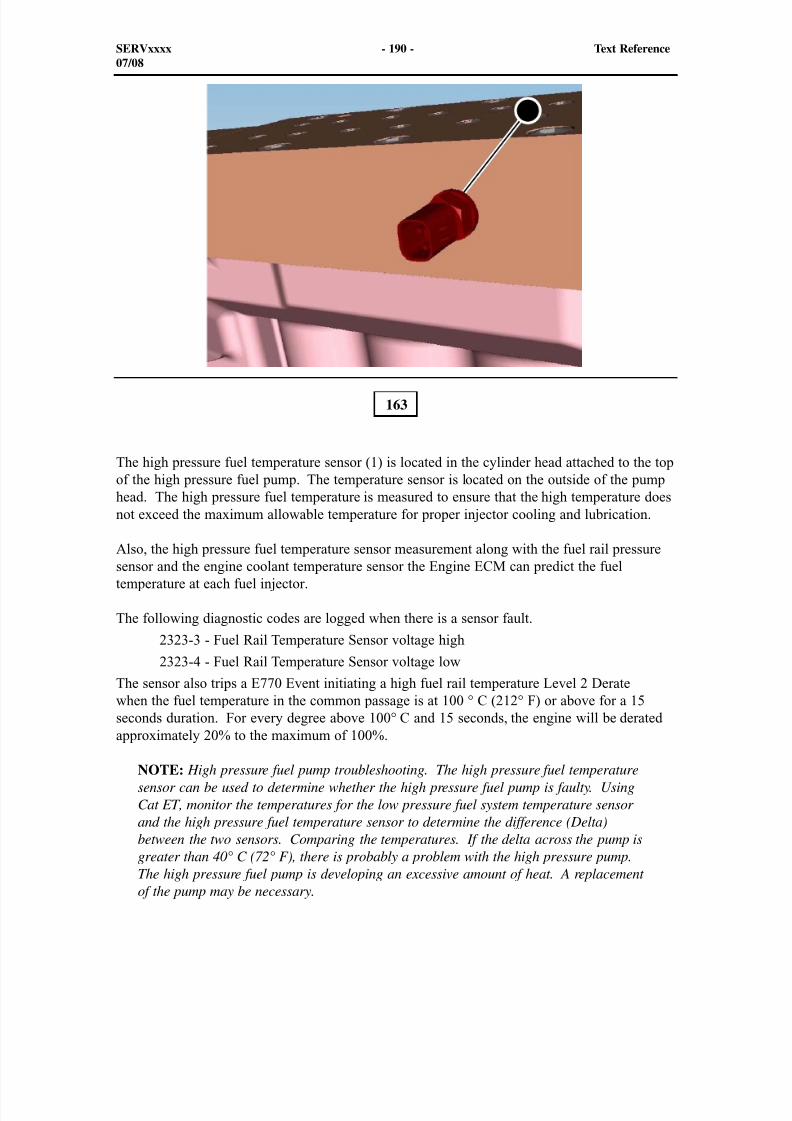
8/9/2019 797F HAA - Meeting Guide.pdf
http://slidepdf.com/reader/full/797f-haa-meeting-guidepdf 205/367
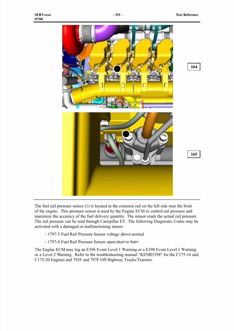
8/9/2019 797F HAA - Meeting Guide.pdf
http://slidepdf.com/reader/full/797f-haa-meeting-guidepdf 206/367
SERVxxxx - 191 - Text Reference07/08
164
165
The fuel rail pressure sensor (1) is located in the common rail on the left side near the frontof the engine. This pressure sensor is used by the Engine ECM to control rail pressure and
maximize the accuracy of the fuel delivery quantity. The sensor reads the actual rail pressure.The rail pressure can be read through Caterpillar ET. The following Diagnostic Codes may beactivated with a damaged or malfunctioning sensor.
- 1797-3 Fuel Rail Pressure Sensor voltage above normal
- 1797-4 Fuel Rail Pressure Sensor open/short to batt+
The Engine ECM may log an E396 Event Level 1 Warning or a E398 Event Level 1 Warningor a Level 2 Warning. Refer to the troubleshooting manual "KENR5398" for the C175-16 andC175-20 Engines and 793F and 797F Off Highway Trucks/Tractors.
1
1
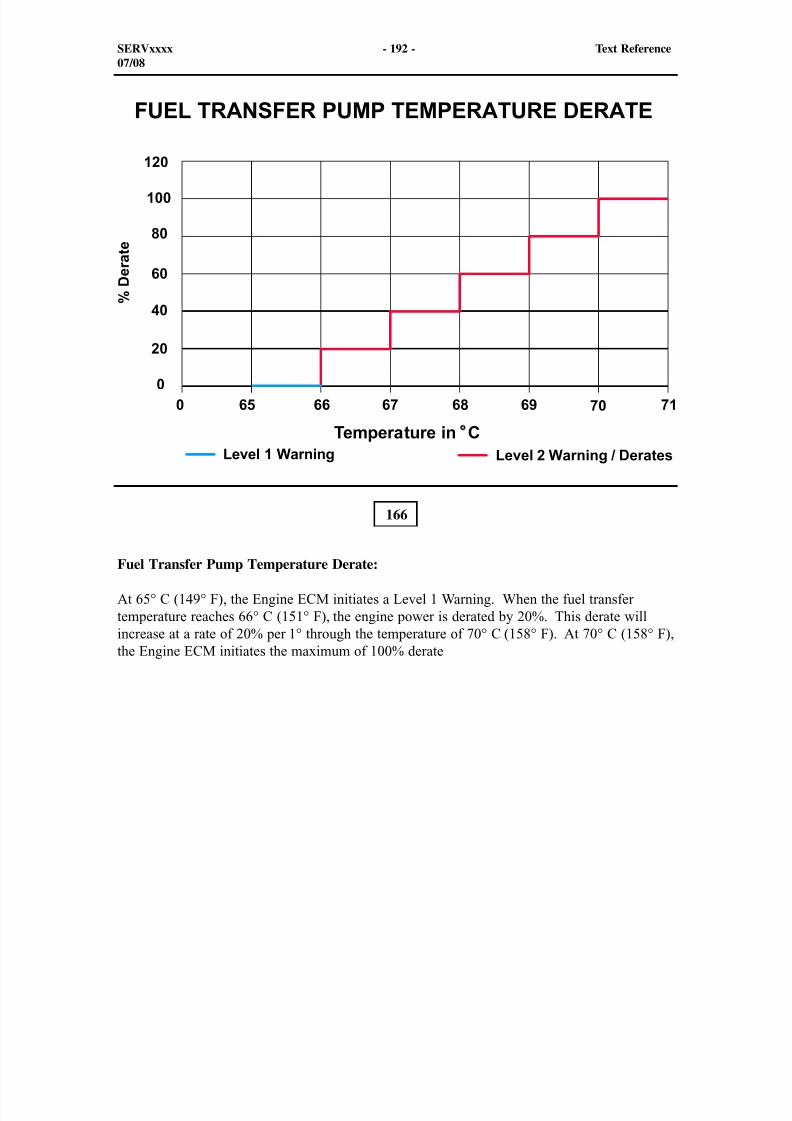
8/9/2019 797F HAA - Meeting Guide.pdf
http://slidepdf.com/reader/full/797f-haa-meeting-guidepdf 207/367
166
Fuel Transfer Pump Temperature Derate:
At 65° C (149° F), the Engine ECM initiates a Level 1 Warning. When the fuel transfertemperature reaches 66° C (151° F), the engine power is derated by 20%. This derate willincrease at a rate of 20% per 1° through the temperature of 70° C (158° F). At 70° C (158° F),the Engine ECM initiates the maximum of 100% derate
SERVxxxx - 192 - Text Reference07/08
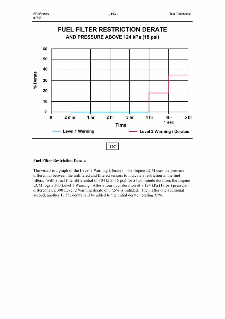
8/9/2019 797F HAA - Meeting Guide.pdf
http://slidepdf.com/reader/full/797f-haa-meeting-guidepdf 208/367
167
Fuel Filter Restriction Derate
The visual is a graph of the Level 2 Warning (Derate). The Engine ECM uses the pressuredifferential between the unfiltered and filtered sensors to indicate a restriction in the fuelfilters. With a fuel filter differential of 104 kPa (15 psi) for a two minute duration, the EngineECM logs a 390 Level 1 Warning. After a four hour duration of a 124 kPa (18 psi) pressuredifferential, a 390 Level 2 Warning derate of 17.5% is initiated. Then, after one additionalsecond, another 17.5% derate will be added to the initial derate, totaling 35%.
SERVxxxx - 193 - Text Reference07/08
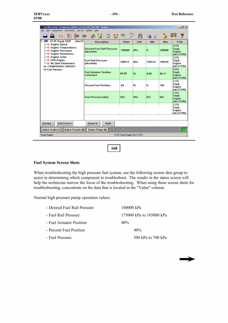
8/9/2019 797F HAA - Meeting Guide.pdf
http://slidepdf.com/reader/full/797f-haa-meeting-guidepdf 209/367
Fuel System Screen Shots
When troubleshooting the high pressure fuel system, use the following screen shot group toassist in determining which component to troubleshoot. The results in the status screen willhelp the technician narrow the focus of the troubleshooting. When using these screen shots fortroubleshooting, concentrate on the data that is located in the "Value" column.
Normal high pressure pump operation values:
- Desired Fuel Rail Pressure 180000 kPa
- Fuel Rail Pressure 175000 kPa to 185000 kPa
- Fuel Actuator Position 40%
- Percent Fuel Position 40%
- Fuel Pressure 500 kPa to 700 kPa
168
SERVxxxx - 194 - Text Reference07/08

8/9/2019 797F HAA - Meeting Guide.pdf
http://slidepdf.com/reader/full/797f-haa-meeting-guidepdf 210/367
SERVxxxx - 195 - Text Reference07/08
This illustration shows a screen shot of a group containing the desired fuel rail pressure, fuelrail pressure, fuel actuator position command (FCV assembly) desired, percent fuel position(FCV assembly) actual, and fuel pressure (abs). The objective of using the status screen is toaccumulate information in order to decide where the fuel system problem originated.
Then, the fuel actuator position command comparison to the percent fuel pressure should beapproximately equal to each other. Also, the fuel pressure (abs) is between the minimum andmaximum pressure. In the following visuals, there should be enough comparison to assist atechnician to troubleshoot the high pressure fuel system.
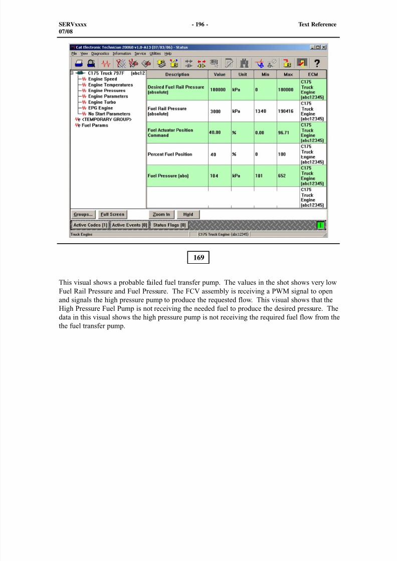
8/9/2019 797F HAA - Meeting Guide.pdf
http://slidepdf.com/reader/full/797f-haa-meeting-guidepdf 211/367
SERVxxxx - 196 - Text Reference07/08
169
This visual shows a probable failed fuel transfer pump. The values in the shot shows very lowFuel Rail Pressure and Fuel Pressure. The FCV assembly is receiving a PWM signal to openand signals the high pressure pump to produce the requested flow. This visual shows that theHigh Pressure Fuel Pump is not receiving the needed fuel to produce the desired pressure. Thedata in this visual shows the high pressure pump is not receiving the required fuel flow from thethe fuel transfer pump.
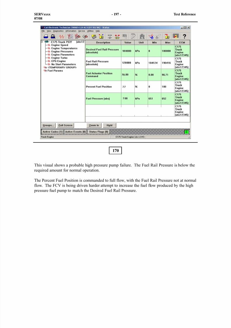
8/9/2019 797F HAA - Meeting Guide.pdf
http://slidepdf.com/reader/full/797f-haa-meeting-guidepdf 212/367
SERVxxxx - 197 - Text Reference07/08
170
This visual shows a probable high pressure pump failure. The Fuel Rail Pressure is below therequired amount for normal operation.
The Percent Fuel Position is commanded to full flow, with the Fuel Rail Pressure not at normalflow. The FCV is being driven harder attempt to increase the fuel flow produced by the high
pressure fuel pump to match the Desired Fuel Rail Pressure.
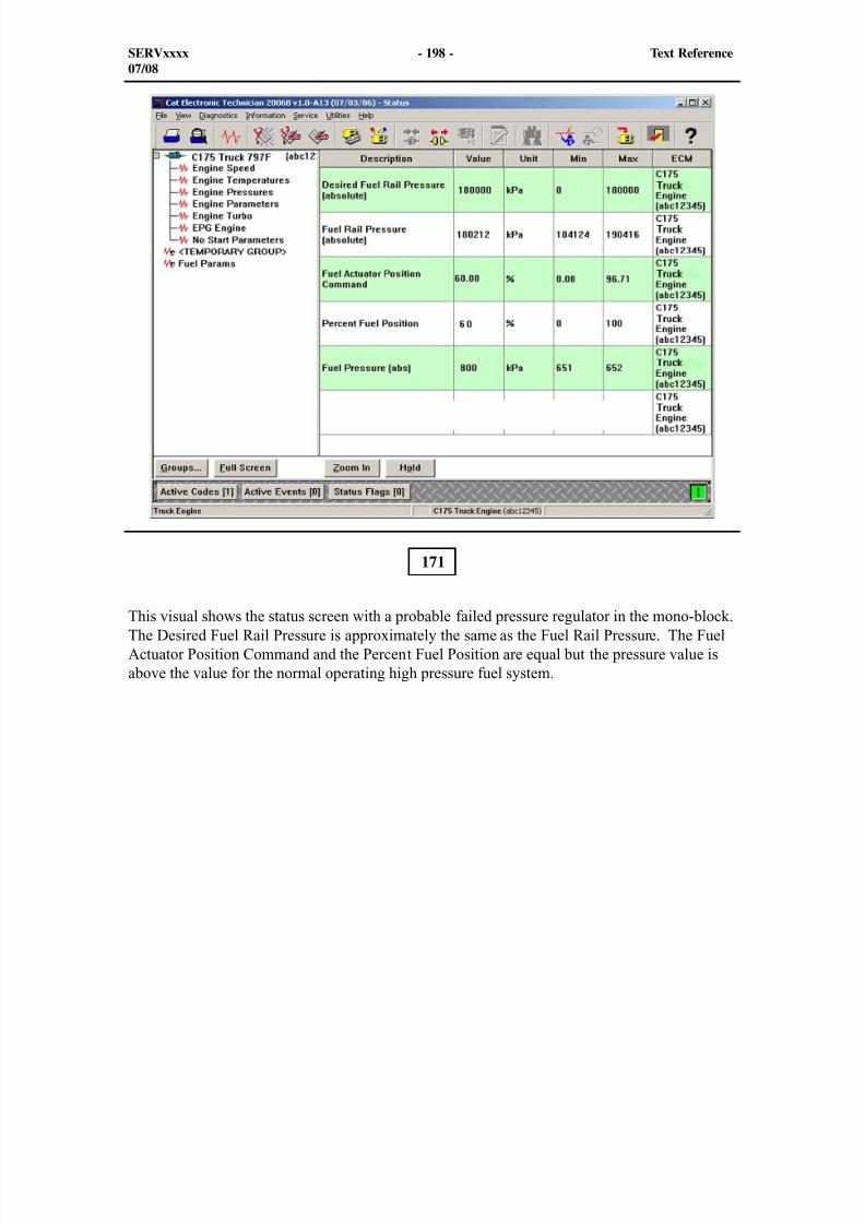
8/9/2019 797F HAA - Meeting Guide.pdf
http://slidepdf.com/reader/full/797f-haa-meeting-guidepdf 213/367
171
This visual shows the status screen with a probable failed pressure regulator in the mono-block.The Desired Fuel Rail Pressure is approximately the same as the Fuel Rail Pressure. The FuelActuator Position Command and the Percent Fuel Position are equal but the pressure value isabove the value for the normal operating high pressure fuel system.
SERVxxxx - 198 - Text Reference07/08
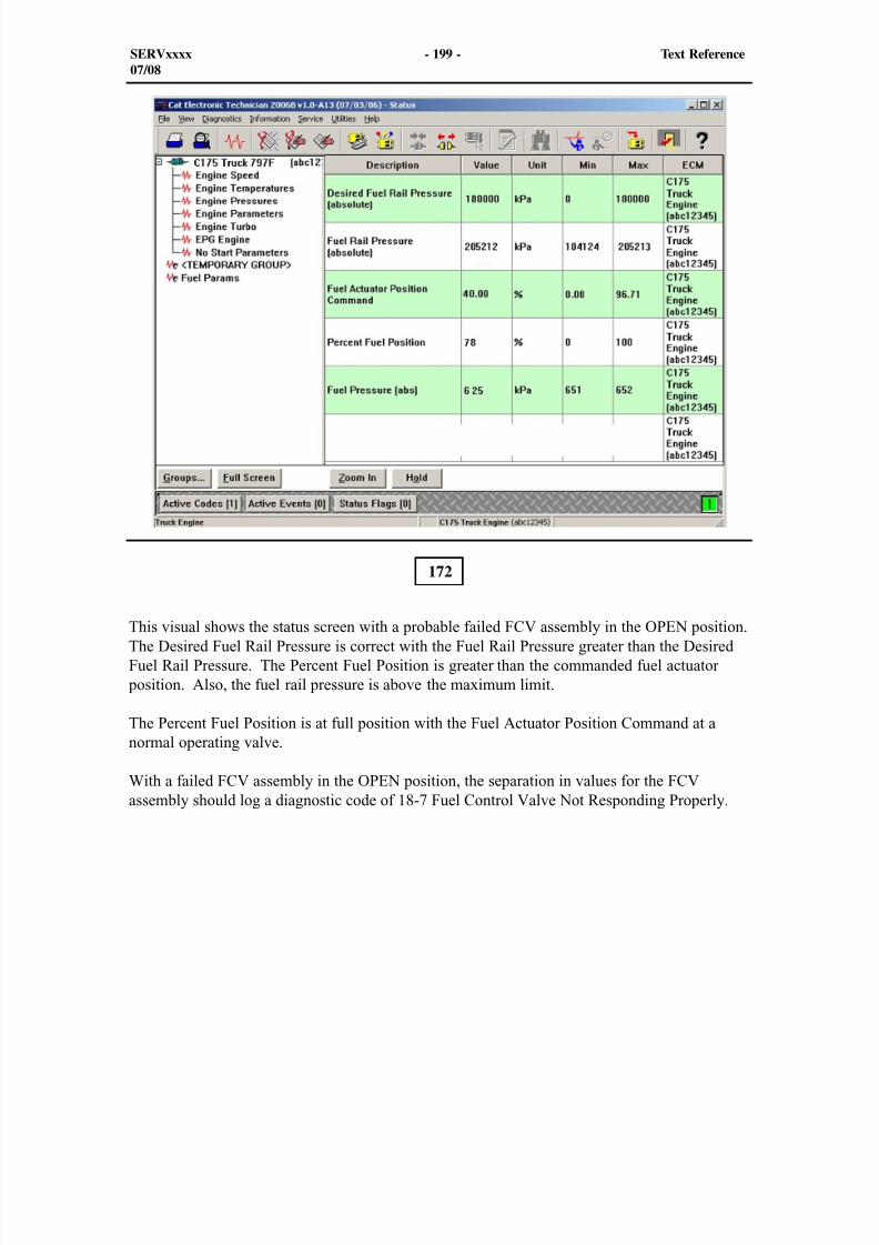
8/9/2019 797F HAA - Meeting Guide.pdf
http://slidepdf.com/reader/full/797f-haa-meeting-guidepdf 214/367
This visual shows the status screen with a probable failed FCV assembly in the OPEN position.The Desired Fuel Rail Pressure is correct with the Fuel Rail Pressure greater than the DesiredFuel Rail Pressure. The Percent Fuel Position is greater than the commanded fuel actuator
position. Also, the fuel rail pressure is above the maximum limit.
The Percent Fuel Position is at full position with the Fuel Actuator Position Command at anormal operating valve.
With a failed FCV assembly in the OPEN position, the separation in values for the FCVassembly should log a diagnostic code of 18-7 Fuel Control Valve Not Responding Properly.
172
SERVxxxx - 199 - Text Reference07/08
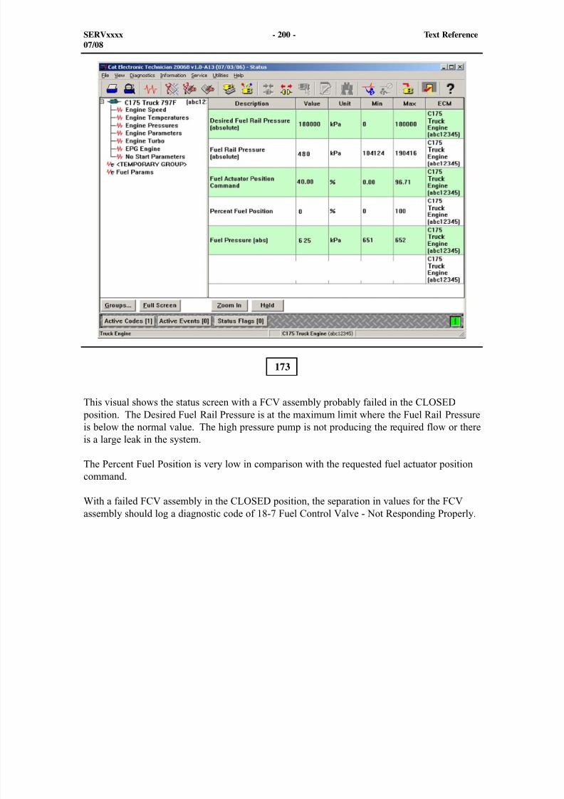
8/9/2019 797F HAA - Meeting Guide.pdf
http://slidepdf.com/reader/full/797f-haa-meeting-guidepdf 215/367
173
This visual shows the status screen with a FCV assembly probably failed in the CLOSED position. The Desired Fuel Rail Pressure is at the maximum limit where the Fuel Rail Pressureis below the normal value. The high pressure pump is not producing the required flow or thereis a large leak in the system.
The Percent Fuel Position is very low in comparison with the requested fuel actuator positioncommand.
With a failed FCV assembly in the CLOSED position, the separation in values for the FCVassembly should log a diagnostic code of 18-7 Fuel Control Valve - Not Responding Properly.
SERVxxxx - 200 - Text Reference07/08
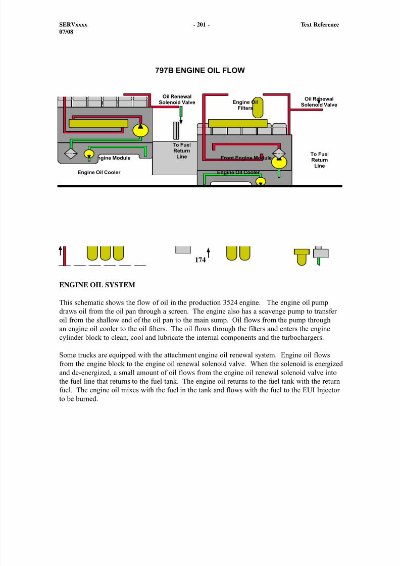
8/9/2019 797F HAA - Meeting Guide.pdf
http://slidepdf.com/reader/full/797f-haa-meeting-guidepdf 216/367
174
ENGINE OIL SYSTEM
This schematic shows the flow of oil in the production 3524 engine. The engine oil pumpdraws oil from the oil pan through a screen. The engine also has a scavenge pump to transferoil from the shallow end of the oil pan to the main sump. Oil flows from the pump throughan engine oil cooler to the oil filters. The oil flows through the filters and enters the enginecylinder block to clean, cool and lubricate the internal components and the turbochargers.
Some trucks are equipped with the attachment engine oil renewal system. Engine oil flowsfrom the engine block to the engine oil renewal solenoid valve. When the solenoid is energizedand de-energized, a small amount of oil flows from the engine oil renewal solenoid valve intothe fuel line that returns to the fuel tank. The engine oil returns to the fuel tank with the returnfuel. The engine oil mixes with the fuel in the tank and flows with the fuel to the EUI Injectorto be burned.
SERVxxxx - 201 - Text Reference07/08
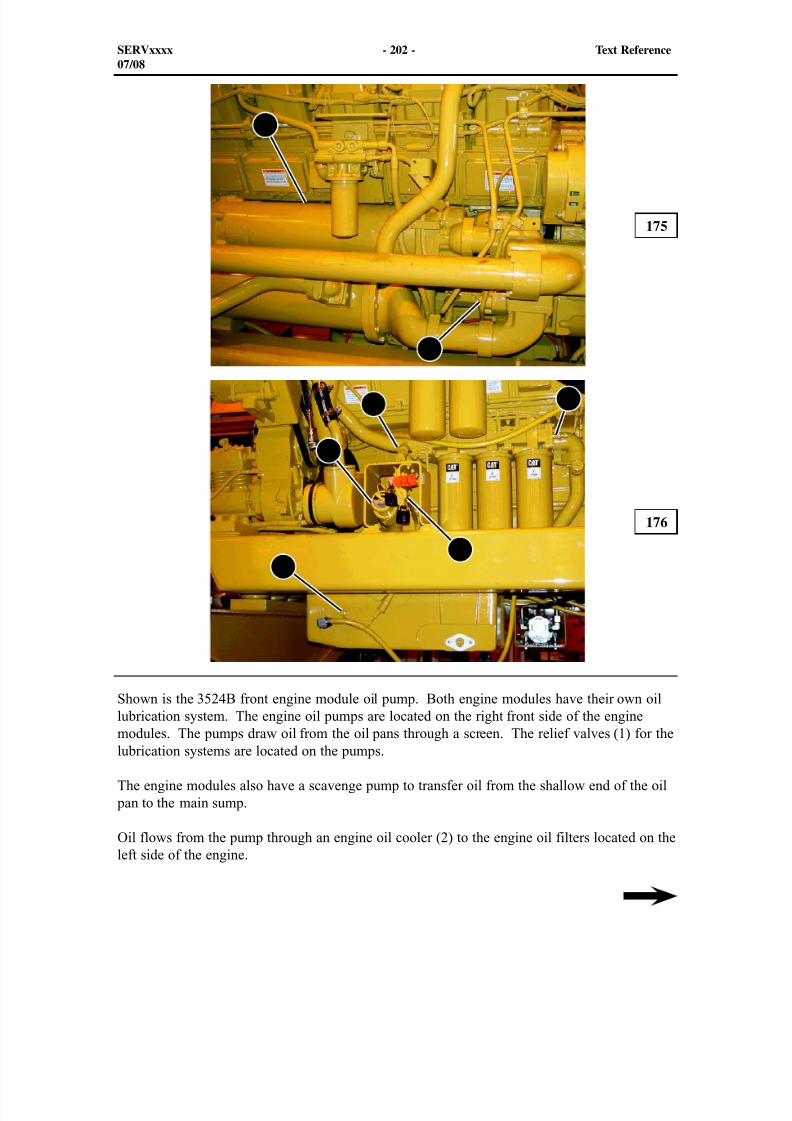
8/9/2019 797F HAA - Meeting Guide.pdf
http://slidepdf.com/reader/full/797f-haa-meeting-guidepdf 217/367
2
1
4
5
3
6
7
Shown is the 3524B front engine module oil pump. Both engine modules have their own oillubrication system. The engine oil pumps are located on the right front side of the engine
modules. The pumps draw oil from the oil pans through a screen. The relief valves (1) for thelubrication systems are located on the pumps.
The engine modules also have a scavenge pump to transfer oil from the shallow end of the oil pan to the main sump.
Oil flows from the pump through an engine oil cooler (2) to the engine oil filters located on theleft side of the engine.
175
176
SERVxxxx - 202 - Text Reference07/08
8/9/2019 797F HAA - Meeting Guide.pdf
http://slidepdf.com/reader/full/797f-haa-meeting-guidepdf 218/367
Oil flows from the engine oil coolers to the three oil filters located on the left side of bothengine modules. The oil flows through the filters and enters the engine cylinder block to clean,cool, and lubricate the internal components and the turbochargers. Engine oil should be addedat the fill tube (3) and checked with the dipstick (4).
The engine lubrication system is equipped with two oil pressure sensors (5). A sensor islocated on each end of the oil filter base. One sensor measures engine oil pressure beforethe filters. The other sensor measures oil pressure after the filters. The sensors provide inputsignals to the engine Slave ECMs. The engine Slave ECMs provide the input signals to theVIMS, which informs the operator of the engine oil pressure. Together, these sensors informthe operator if the engine oil filters are restricted.
An engine oil level switch (6) provides input signals to the engine Slave ECMs. The engineSlave ECMs provide the signal to the VIMS, which informs the operator of the engine oil level.
On both engine modules, the fitting (7) can be used to drain the engine oil that is trapped abovethe filters. Do not add oil through the fitting because unfiltered oil will enter the engine. Anycontamination could cause damage to the engine.
NOTE: When changing the engine oil filters, drain the engine oil that is trappedabove the oil filters through the fitting (5) to prevent spilling the oil. Oil added tothe engine through the fitting will go directly to the main oil galleries without goingthrough the engine oil filters. Adding oil to the engine through the fitting may introducecontaminant's into the system and cause damage to the engine.
SERVxxxx - 203 - Text Reference07/08
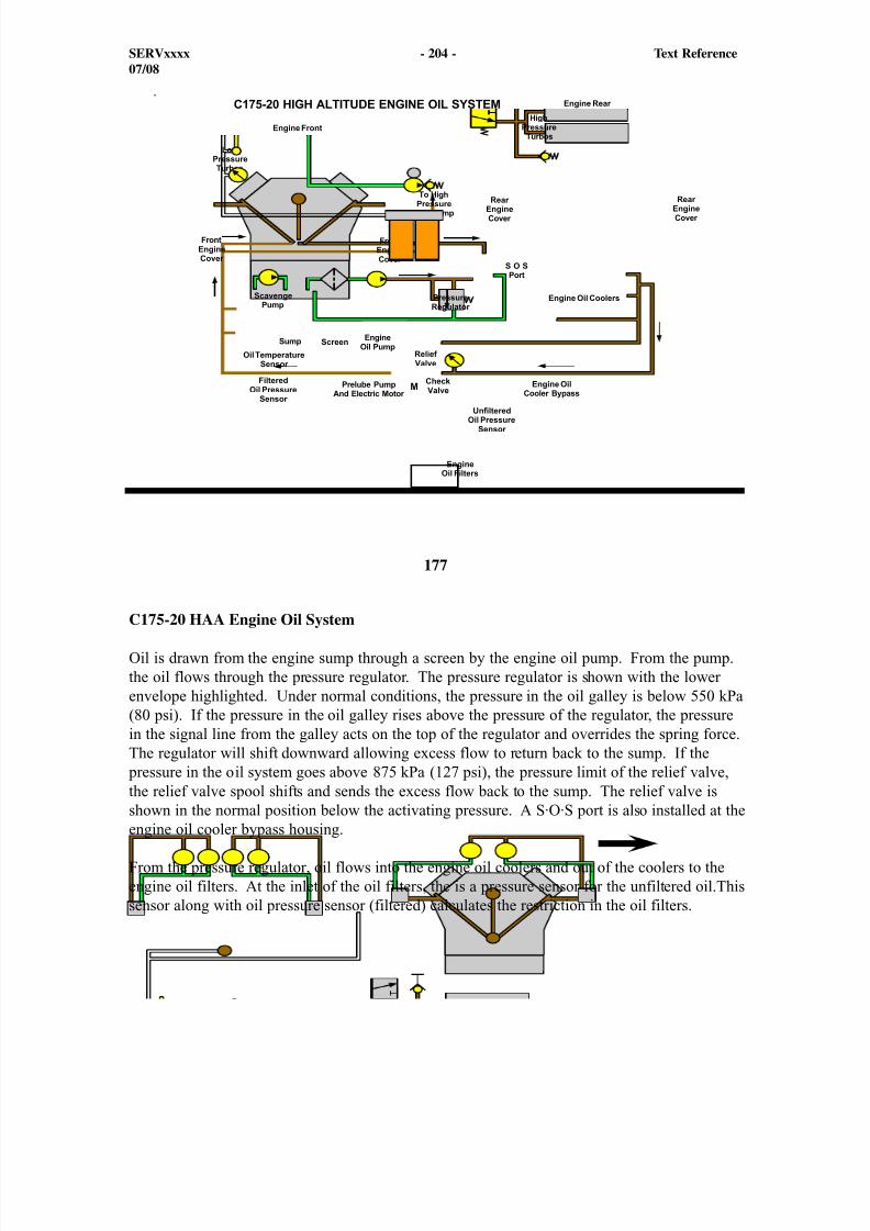
8/9/2019 797F HAA - Meeting Guide.pdf
http://slidepdf.com/reader/full/797f-haa-meeting-guidepdf 219/367
177
C175-20 HAA Engine Oil System
Oil is drawn from the engine sump through a screen by the engine oil pump. From the pump.the oil flows through the pressure regulator. The pressure regulator is shown with the lowerenvelope highlighted. Under normal conditions, the pressure in the oil galley is below 550 kPa(80 psi). If the pressure in the oil galley rises above the pressure of the regulator, the pressurein the signal line from the galley acts on the top of the regulator and overrides the spring force.The regulator will shift downward allowing excess flow to return back to the sump. If the
pressure in the oil system goes above 875 kPa (127 psi), the pressure limit of the relief valve,the relief valve spool shifts and sends the excess flow back to the sump. The relief valve isshown in the normal position below the activating pressure. A S·O·S port is also installed at theengine oil cooler bypass housing.
From the pressure regulator, oil flows into the engine oil coolers and out of the coolers to theengine oil filters. At the inlet of the oil filters, the is a pressure sensor for the unfiltered oil.Thissensor along with oil pressure sensor (filtered) calculates the restriction in the oil filters.
SERVxxxx - 204 - Text Reference07/08
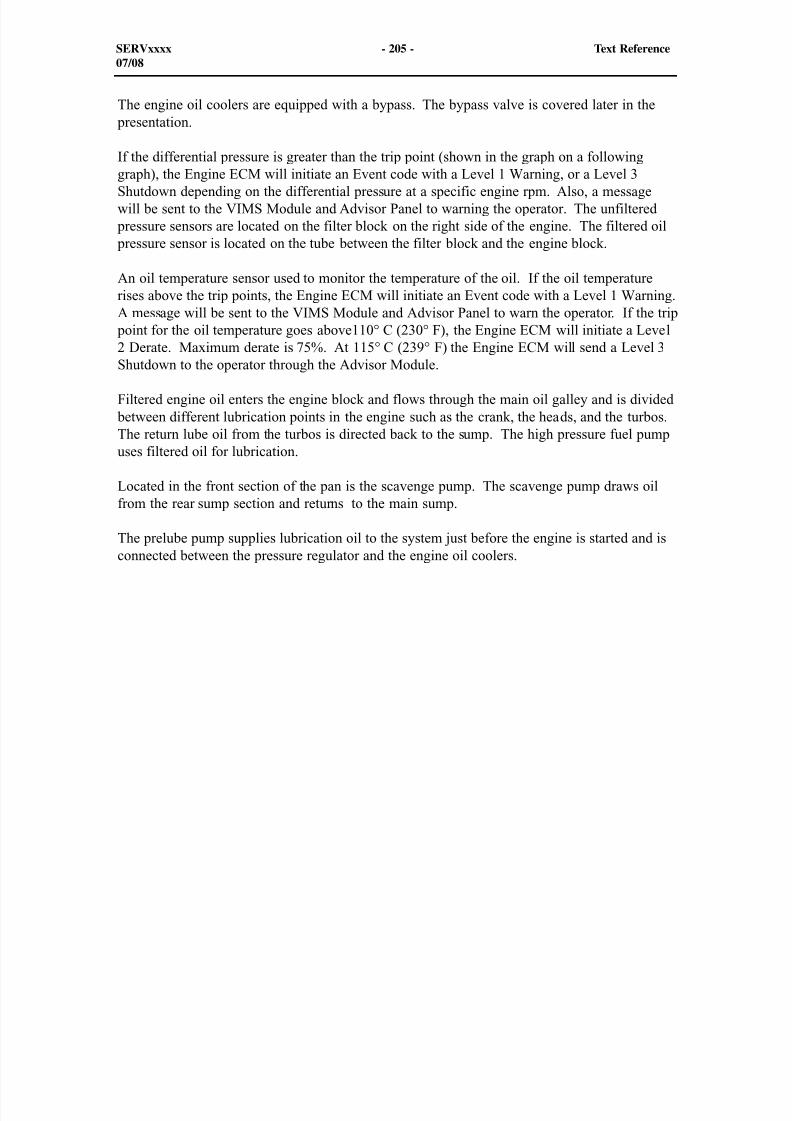
8/9/2019 797F HAA - Meeting Guide.pdf
http://slidepdf.com/reader/full/797f-haa-meeting-guidepdf 220/367
The engine oil coolers are equipped with a bypass. The bypass valve is covered later in the presentation.
If the differential pressure is greater than the trip point (shown in the graph on a followinggraph), the Engine ECM will initiate an Event code with a Level 1 Warning, or a Level 3Shutdown depending on the differential pressure at a specific engine rpm. Also, a messagewill be sent to the VIMS Module and Advisor Panel to warning the operator. The unfiltered
pressure sensors are located on the filter block on the right side of the engine. The filtered oil pressure sensor is located on the tube between the filter block and the engine block.
An oil temperature sensor used to monitor the temperature of the oil. If the oil temperaturerises above the trip points, the Engine ECM will initiate an Event code with a Level 1 Warning.A message will be sent to the VIMS Module and Advisor Panel to warn the operator. If the trip
point for the oil temperature goes above110° C (230° F), the Engine ECM will initiate a Level2 Derate. Maximum derate is 75%. At 115° C (239° F) the Engine ECM will send a Level 3
Shutdown to the operator through the Advisor Module.
Filtered engine oil enters the engine block and flows through the main oil galley and is divided between different lubrication points in the engine such as the crank, the heads, and the turbos.The return lube oil from the turbos is directed back to the sump. The high pressure fuel pumpuses filtered oil for lubrication.
Located in the front section of the pan is the scavenge pump. The scavenge pump draws oilfrom the rear sump section and returns to the main sump.
The prelube pump supplies lubrication oil to the system just before the engine is started and isconnected between the pressure regulator and the engine oil coolers.
SERVxxxx - 205 - Text Reference07/08
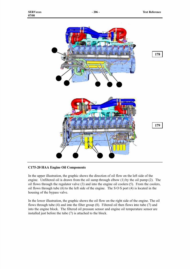
8/9/2019 797F HAA - Meeting Guide.pdf
http://slidepdf.com/reader/full/797f-haa-meeting-guidepdf 221/367
C175-20 HAA Engine Oil Components
In the upper illustration, the graphic shows the direction of oil flow on the left side of theengine. Unfiltered oil is drawn from the oil sump through elbow (1) by the oil pump (2). Theoil flows through the regulator valve (3) and into the engine oil coolers (5). From the coolers,oil flows through tube (6) to the left side of the engine. The S·O·S port (4) is located in thehousing of the bypass valve.
In the lower illustration, the graphic shows the oil flow on the right side of the engine. The oilflows through tube (4) and into the filter group (8). Filtered oil then flows into tube (7) andinto the engine block. The filtered oil pressure sensor and engine oil temperature sensor areinstalled just before the tube (7) is attached to the block.
178
179
SERVxxxx - 206 - Text Reference07/08
1
2
3
6
4 87 9
4 5
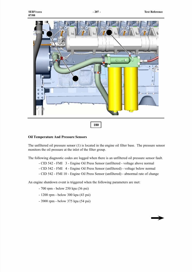
8/9/2019 797F HAA - Meeting Guide.pdf
http://slidepdf.com/reader/full/797f-haa-meeting-guidepdf 222/367
180
SERVxxxx - 207 - Text Reference07/08
12
3
Oil Temperature And Pressure Sensors
The unfiltered oil pressure sensor (1) is located in the engine oil filter base. The pressure sensormonitors the oil pressure at the inlet of the filter group.
The following diagnostic codes are logged when there is an unfiltered oil pressure sensor fault.
- CID 542 - FMI 3 - Engine Oil Press Sensor (unfiltered - voltage above normal
- CID 542 - FMI 4 - Engine Oil Press Sensor (unfiltered) - voltage below normal
- CID 542 - FMI 10 - Engine Oil Press Sensor (unfiltered) - abnormal rate of change
An engine shutdown event is triggered when the following parameters are met:
- 700 rpm - below 250 kpa (36 psi)
- 1200 rpm - below 300 kpa (43 psi)
- 2000 rpm - below 375 kpa (54 psi)
8/9/2019 797F HAA - Meeting Guide.pdf
http://slidepdf.com/reader/full/797f-haa-meeting-guidepdf 223/367
The filtered oil pressure sensor (2) is located in the tube on the right rear side going into theengine block. The sensor is used to assist the Engine ECM in monitoring engine oil pressurethrough the filter group. The Engine ECM uses the data from the pressure sensor to calculatethe differential pressure between the filtered oil pressure and the unfiltered oil pressure. Thisinformation is used to detect plugged or plugging oil filters. This pressure sensor initiates a
plugged oil filter E099 Event Level 1 Warning, with a warning sent to the Advisor Panel. Thiswill warn the operator
The filtered oil pressure sensor pressure data that is sent to the Engine ECM is also used as thedetermining pressure for the low engine oil pressure event control.
The following diagnostic codes maybe logged when there is a unfiltered oil pressure sensorfault.
- CID 100 - FMI 3 - Engine Oil Pressure Sensor (filtered) - voltage above normal
- CID 100 - FMI 4 - Engine Oil Pressure Sensor (Filtered) - voltage below normal - CID 100 - FMI 10 - Engine Oil Pressure Sensor (filtered) - abnormal rate of change
The engine oil temperature sensor (3) is located at the rear of the engine also in the tube asshown in the visual. The temperature sensor is used to monitor the engine oil temperaturefor engine protection strategies. The oil temperature must be monitored to inform theoperator through the Advisor panel that the oil temperature is above the limit. There is no oiltemperature sensor for the oil that is leaving the engine block.
Diagnostic Codes:
- CID 175 - FMI 3 - Engine oil temperature sensor voltage above normal
- CID 175 - FMI 4 - Engine oil temperature sensor voltage below normal
The engine oil temperature sensor signals the Engine ECM to initiate a high engine oiltemperature E197Level 1 Warning, a E197 Level 2 Derate, or a E197 Level 3 Shutdown event.The trip points are graphed out on the following page.
SERVxxxx - 208 - Text Reference07/08
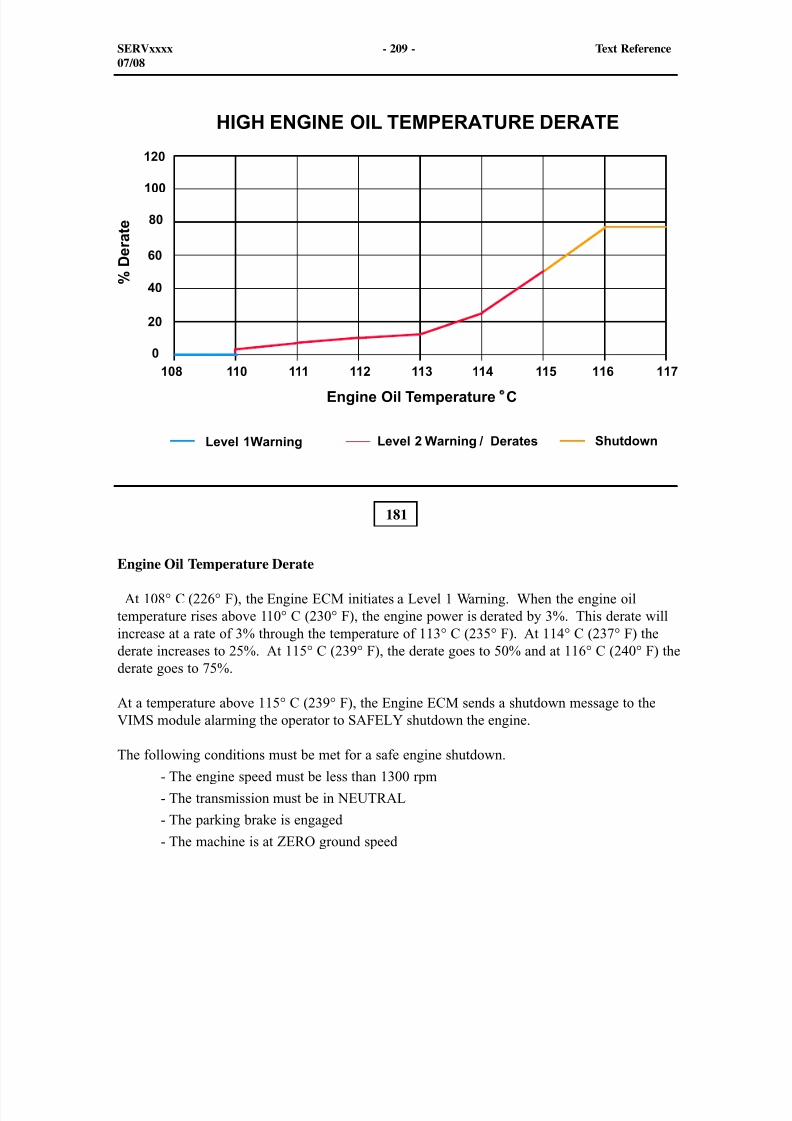
8/9/2019 797F HAA - Meeting Guide.pdf
http://slidepdf.com/reader/full/797f-haa-meeting-guidepdf 224/367
181
Engine Oil Temperature Derate
At 108° C (226° F), the Engine ECM initiates a Level 1 Warning. When the engine oiltemperature rises above 110° C (230° F), the engine power is derated by 3%. This derate willincrease at a rate of 3% through the temperature of 113° C (235° F). At 114° C (237° F) thederate increases to 25%. At 115° C (239° F), the derate goes to 50% and at 116° C (240° F) thederate goes to 75%.
At a temperature above 115° C (239° F), the Engine ECM sends a shutdown message to theVIMS module alarming the operator to SAFELY shutdown the engine.
The following conditions must be met for a safe engine shutdown.
- The engine speed must be less than 1300 rpm
- The transmission must be in NEUTRAL
- The parking brake is engaged
- The machine is at ZERO ground speed
SERVxxxx - 209 - Text Reference07/08
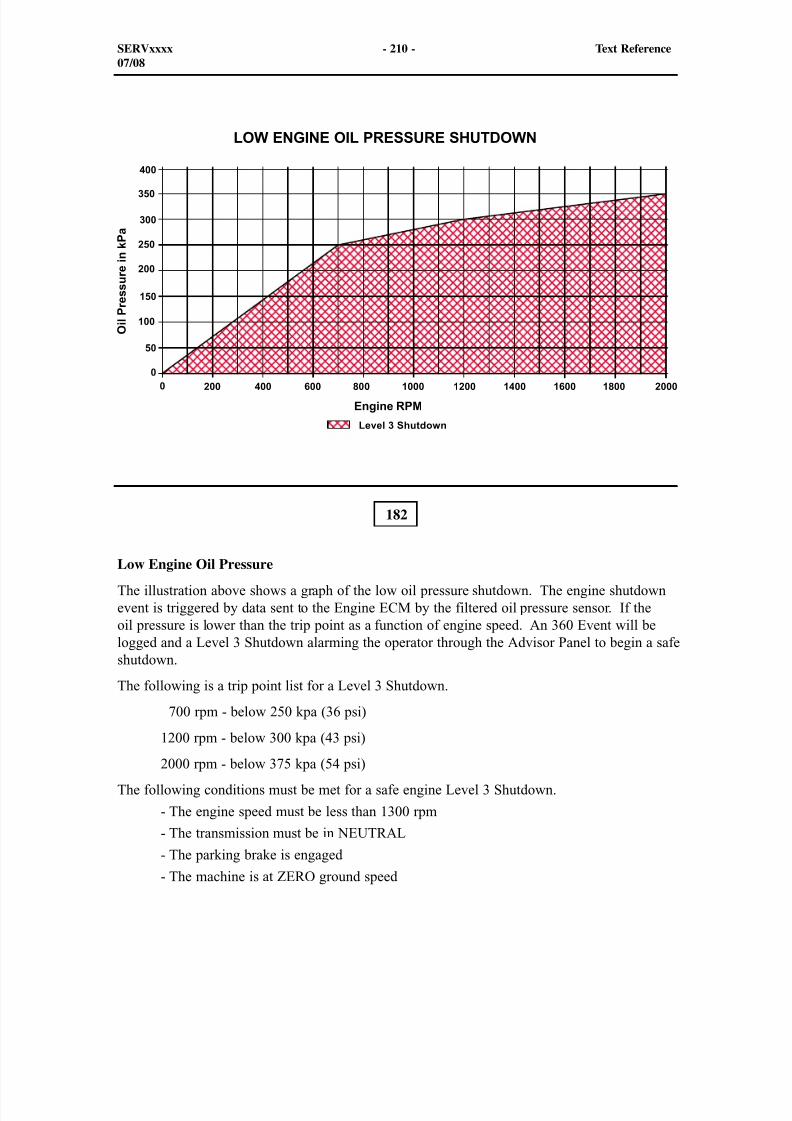
8/9/2019 797F HAA - Meeting Guide.pdf
http://slidepdf.com/reader/full/797f-haa-meeting-guidepdf 225/367
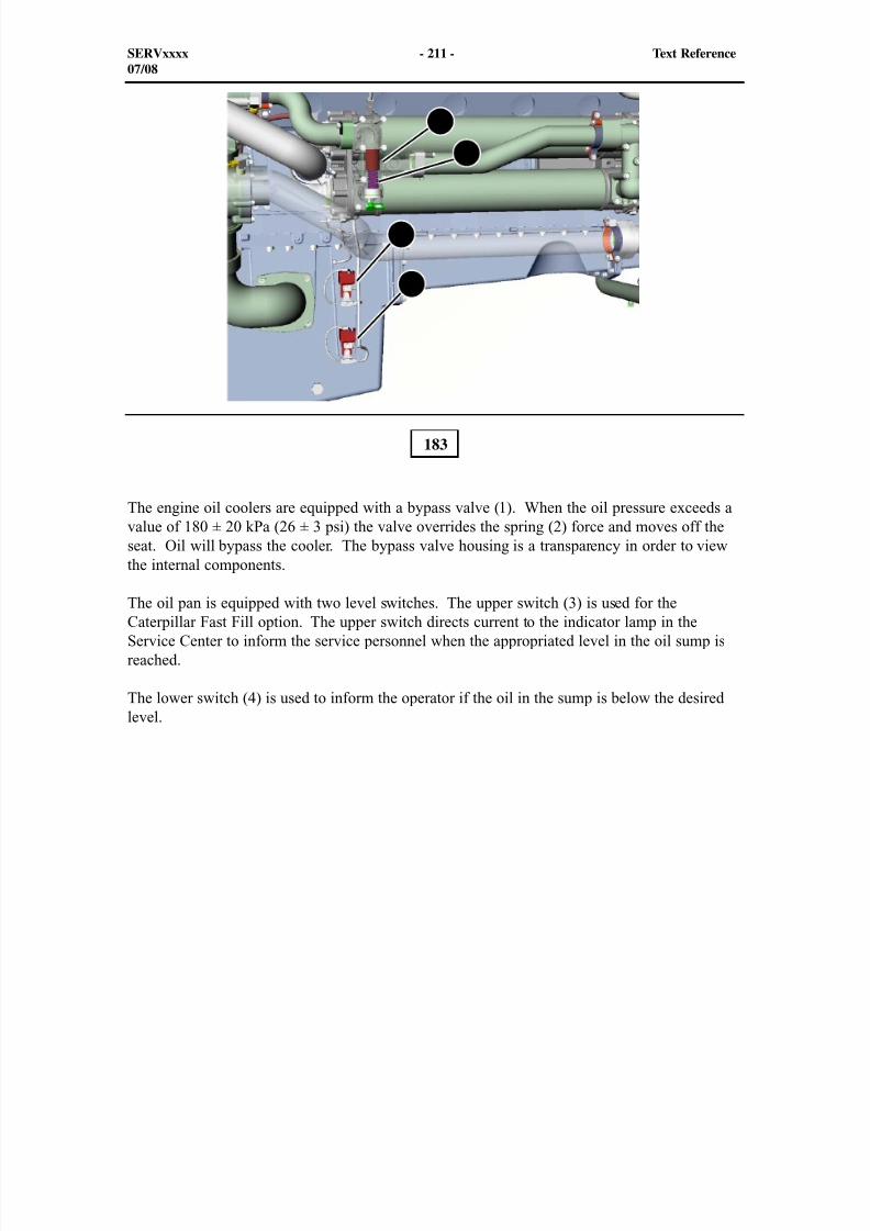
8/9/2019 797F HAA - Meeting Guide.pdf
http://slidepdf.com/reader/full/797f-haa-meeting-guidepdf 226/367
The engine oil coolers are equipped with a bypass valve (1). When the oil pressure exceeds avalue of 180 ± 20 kPa (26 ± 3 psi) the valve overrides the spring (2) force and moves off theseat. Oil will bypass the cooler. The bypass valve housing is a transparency in order to viewthe internal components.
The oil pan is equipped with two level switches. The upper switch (3) is used for theCaterpillar Fast Fill option. The upper switch directs current to the indicator lamp in theService Center to inform the service personnel when the appropriated level in the oil sump isreached.
The lower switch (4) is used to inform the operator if the oil in the sump is below the desiredlevel.
183
SERVxxxx - 211 - Text Reference07/08
1
2
3
4
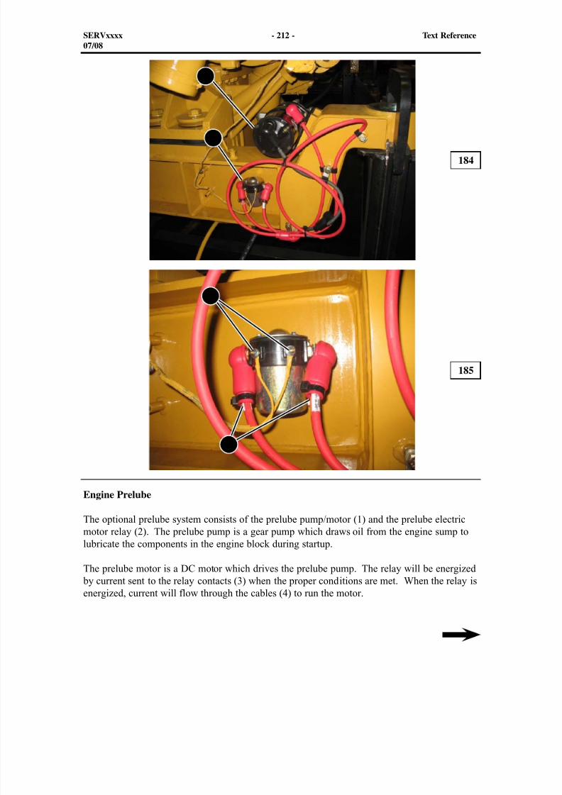
8/9/2019 797F HAA - Meeting Guide.pdf
http://slidepdf.com/reader/full/797f-haa-meeting-guidepdf 227/367
Engine Prelube
The optional prelube system consists of the prelube pump/motor (1) and the prelube electricmotor relay (2). The prelube pump is a gear pump which draws oil from the engine sump tolubricate the components in the engine block during startup.
The prelube motor is a DC motor which drives the prelube pump. The relay will be energized by current sent to the relay contacts (3) when the proper conditions are met. When the relay isenergized, current will flow through the cables (4) to run the motor.
184
185
SERVxxxx - 212 - Text Reference07/08
1
2
3
4

8/9/2019 797F HAA - Meeting Guide.pdf
http://slidepdf.com/reader/full/797f-haa-meeting-guidepdf 228/367
The prelube system has four states:
- Prelube is Off/Failed
- Prelube is ready to start or prelube continuous
- Prelube is waiting for oil (system waiting for a pressure gauge value of 6 kpa (1 psi)) - Prelube is disabled (not installed)
The prelube relay diagnostic codes are as follows
- CID 338 - FMI 5 - Engine Pre-lube pump relay: current below normal
- CID 338 - FMI 6 - Engine Pre-lube pump relay: current above normal
The prelube pump will run for 45 seconds or the pump will supply enough flow to supply
48 kPa (7 psi) before ending the cycle.
If the prelube pressure drops below 48 kPa (7 psi) the Engine ECM logs a E233 Event - LowEngine Pre-lube Pressure. The 233 Event event will initiate a Level 3 Shutdown.
SERVxxxx - 213 - Text Reference07/08
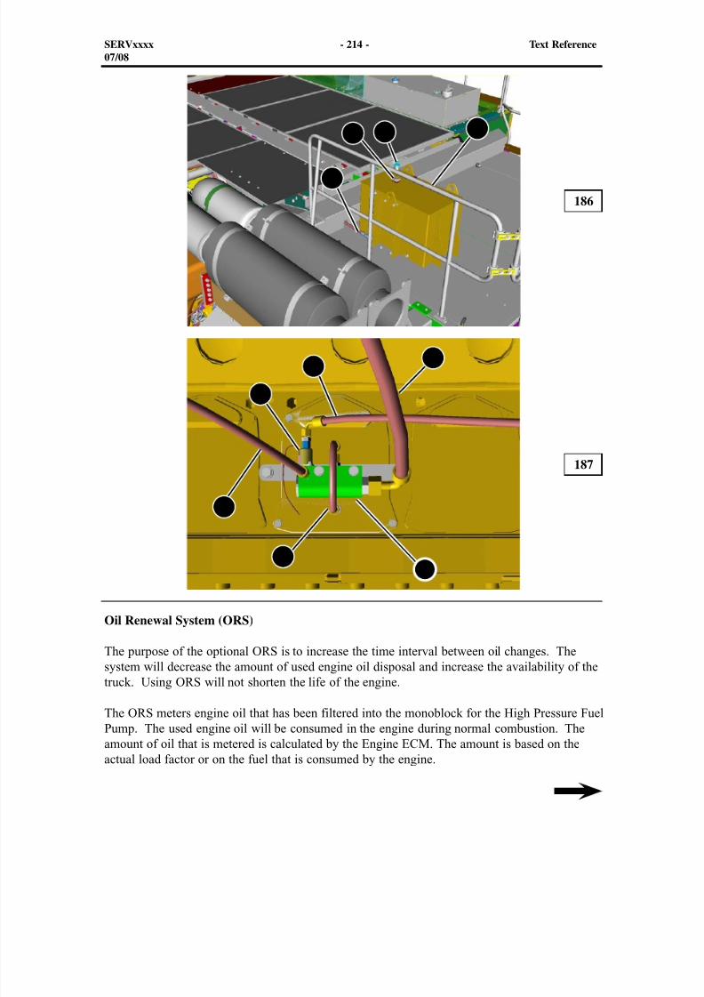
8/9/2019 797F HAA - Meeting Guide.pdf
http://slidepdf.com/reader/full/797f-haa-meeting-guidepdf 229/367
12
4
5
6
7
4
Oil Renewal System (ORS)
The purpose of the optional ORS is to increase the time interval between oil changes. Thesystem will decrease the amount of used engine oil disposal and increase the availability of thetruck. Using ORS will not shorten the life of the engine.
The ORS meters engine oil that has been filtered into the monoblock for the High Pressure FuelPump. The used engine oil will be consumed in the engine during normal combustion. Theamount of oil that is metered is calculated by the Engine ECM. The amount is based on theactual load factor or on the fuel that is consumed by the engine.
186
187
SERVxxxx - 214 - Text Reference07/08
8
3
9

8/9/2019 797F HAA - Meeting Guide.pdf
http://slidepdf.com/reader/full/797f-haa-meeting-guidepdf 230/367
Whenever used oil from the oil sump is injected into the return fuel line, oil from an optionalmakeup tank (1) is added to the oil sump through hose (8). Regular additions of new oil willallow the oil change interval to be extended. Regular S·O·S Oil Analysis will determinewhether an oil change is required.
The upper illustration shows the location of the ORS make-up tank (1) on top of the platform.The tank consists of a fill tube (3) and an oil level sensor (2). The sensor signals the EngineECM when the oil in the make-up tank is below the necessary level. Hose (4) is the supply linethat is connected between the make-up tank and the ORS valve.
The lower illustration shows the ORS valve (9) with the connections for the flow of used oil.Hose (7) supplies the used filtered oil from the oil filter to the ORS valve. Hose (5) routes theused filtered oil from the valve to the monoblock of the high pressure fuel pump.
Troubleshooting the ORS
Check to see if the ORS is enabled in Cat ET before troubleshooting the system.
Disconnect the rubber hose (5) from the monoblock (not shown). Connect the open end of thehose to a container. Install a plug in the monoblock connector before starting the engine.
Use the override function in Cat ET to enable the ORS. The ORS valve will operate whennormal operating parameters are met.
If oil does not flow out of the hose and fill the container, check the following items.
- Engine oil level
- Fuel level
- Engine oil filters
- Restricted hose
- Electronic faults
The following are diagnostic codes for the ORS solenoid valve. This valve has a MID 033Diagnostic Code which is engine.
- CID O569 - FMI 05 Solenoid valve, open or short to +battery
- CID O569 - FMI 06 Solenoid valve, short to ground
SERVxxxx - 215 - Text Reference07/08
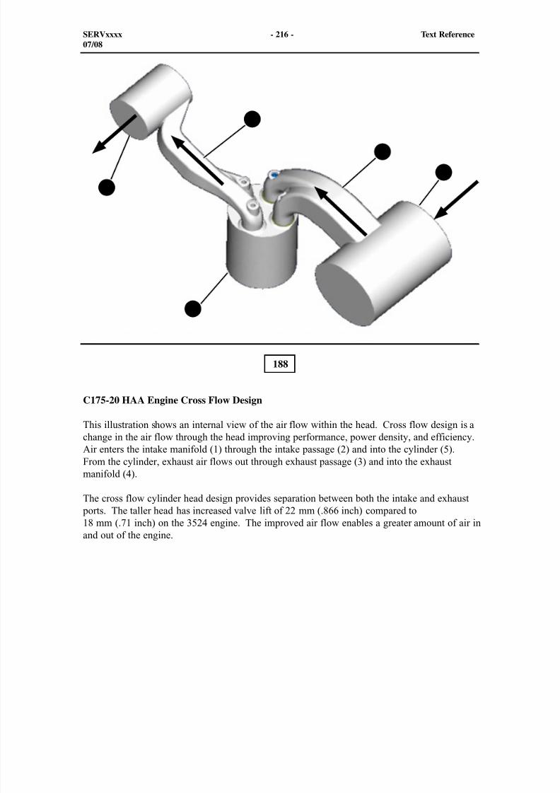
8/9/2019 797F HAA - Meeting Guide.pdf
http://slidepdf.com/reader/full/797f-haa-meeting-guidepdf 231/367
188
C175-20 HAA Engine Cross Flow Design
This illustration shows an internal view of the air flow within the head. Cross flow design is achange in the air flow through the head improving performance, power density, and efficiency.Air enters the intake manifold (1) through the intake passage (2) and into the cylinder (5).From the cylinder, exhaust air flows out through exhaust passage (3) and into the exhaustmanifold (4).
The cross flow cylinder head design provides separation between both the intake and exhaust ports. The taller head has increased valve lift of 22 mm (.866 inch) compared to18 mm (.71 inch) on the 3524 engine. The improved air flow enables a greater amount of air inand out of the engine.
SERVxxxx - 216 - Text Reference07/08
1
2
3
4
5
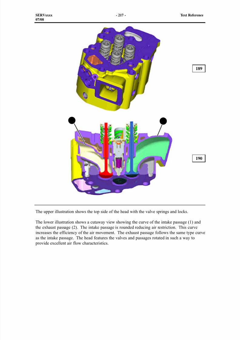
8/9/2019 797F HAA - Meeting Guide.pdf
http://slidepdf.com/reader/full/797f-haa-meeting-guidepdf 232/367
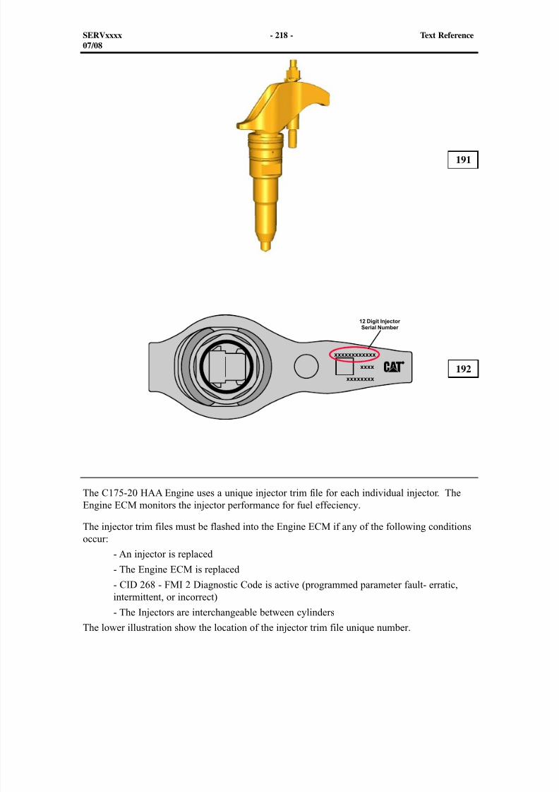
8/9/2019 797F HAA - Meeting Guide.pdf
http://slidepdf.com/reader/full/797f-haa-meeting-guidepdf 233/367
The C175-20 HAA Engine uses a unique injector trim file for each individual injector. TheEngine ECM monitors the injector performance for fuel effeciency.
The injector trim files must be flashed into the Engine ECM if any of the following conditionsoccur:
- An injector is replaced
- The Engine ECM is replaced
- CID 268 - FMI 2 Diagnostic Code is active (programmed parameter fault- erratic,intermittent, or incorrect)
- The Injectors are interchangeable between cylinders
The lower illustration show the location of the injector trim file unique number.
SERVxxxx - 218 - Text Reference07/08
191
192
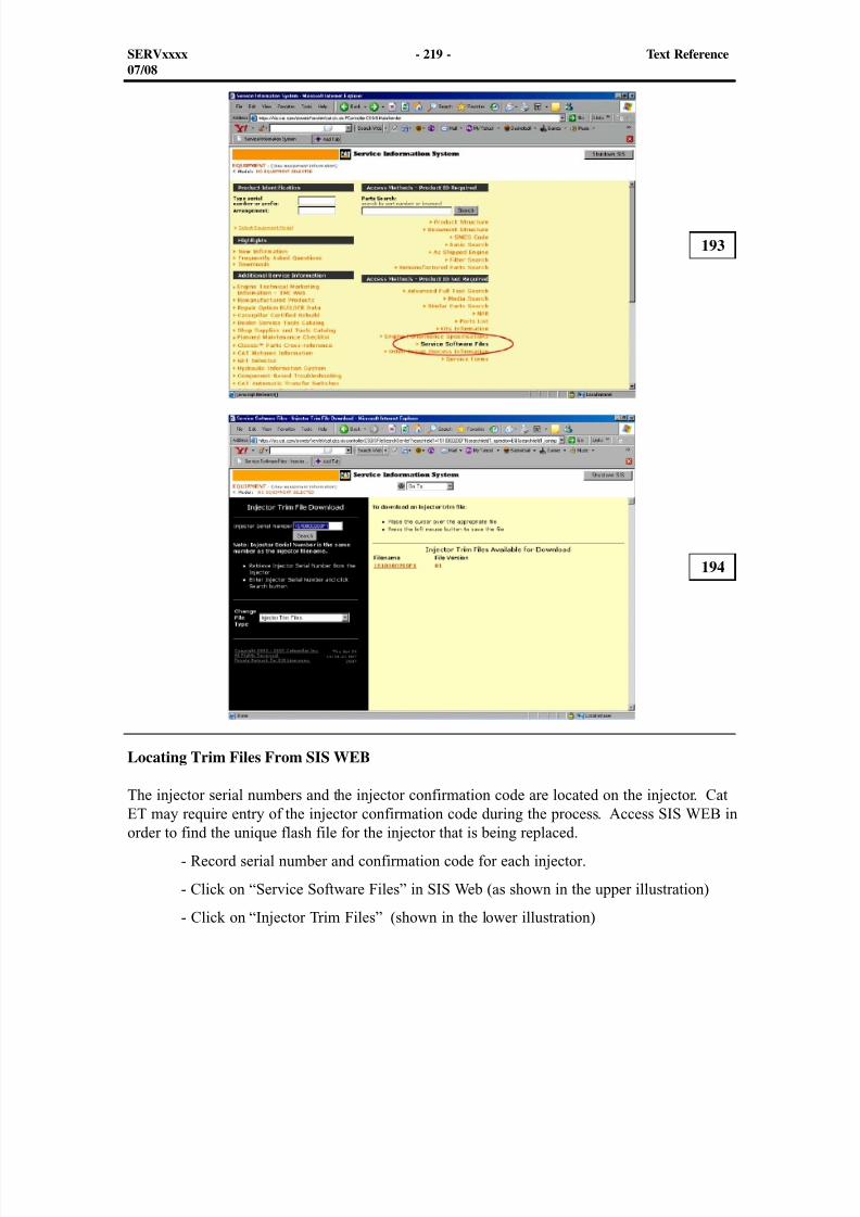
8/9/2019 797F HAA - Meeting Guide.pdf
http://slidepdf.com/reader/full/797f-haa-meeting-guidepdf 234/367
SERVxxxx - 219 - Text Reference07/08
193
194
Locating Trim Files From SIS WEB
The injector serial numbers and the injector confirmation code are located on the injector. CatET may require entry of the injector confirmation code during the process. Access SIS WEB inorder to find the unique flash file for the injector that is being replaced.
- Record serial number and confirmation code for each injector.
- Click on “Service Software Files” in SIS Web (as shown in the upper illustration)
- Click on “Injector Trim Files” (shown in the lower illustration)
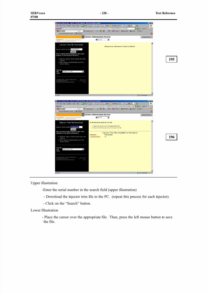
8/9/2019 797F HAA - Meeting Guide.pdf
http://slidepdf.com/reader/full/797f-haa-meeting-guidepdf 235/367
Upper illustration
-Enter the serial number in the search field (upper illustration)
- Download the injector trim file to the PC. (repeat this process for each injector).
- Click on the “Search” button.
Lower Illustration
- Place the cursor over the appropriate file. Then, press the left mouse button to savethe file.
196
195
SERVxxxx - 220 - Text Reference07/08
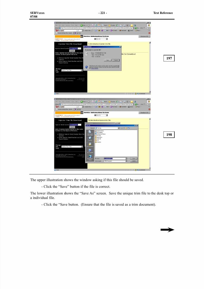
8/9/2019 797F HAA - Meeting Guide.pdf
http://slidepdf.com/reader/full/797f-haa-meeting-guidepdf 236/367
197
SERVxxxx - 221 - Text Reference07/08
The upper illustration shows the window asking if this file should be saved.
- Click the “Save” button if the file is correct.
The lower illustration shows the “Save As” screen. Save the unique trim file to the desk top ora individual file.
- Click the “Save button. (Ensure that the file is saved as a trim document).
198
8/9/2019 797F HAA - Meeting Guide.pdf
http://slidepdf.com/reader/full/797f-haa-meeting-guidepdf 237/367
SERVxxxx - 222 - Text Reference07/08
The flash file is read to be flashed. Perform the following steps in order to flash the injector.
- Connect Cat ET
- At the menu, select “Service”, “Calibrations”, and “Injector Trim Calibration”
- Select the appropriate cylinder - Click the “Change” button
- Select the appropriate injector trim file from the PC
- Click the “Open” button
- If you are prompted, enter the injector confirmation code
- Click the “OK” button (the injector trim file is loaded into Cat ET)
- Repeat the procedure for each cylinder, as required
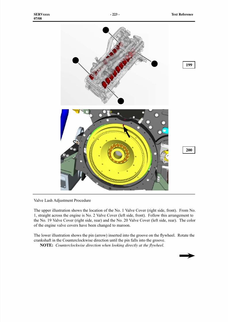
8/9/2019 797F HAA - Meeting Guide.pdf
http://slidepdf.com/reader/full/797f-haa-meeting-guidepdf 238/367
199
200
Valve Lash Adjustment Procedure
The upper illustration shows the location of the No. 1 Valve Cover (right side, front). From No.1, straight across the engine is No. 2 Valve Cover (left side, front). Follow this arrangement tothe No. 19 Valve Cover (right side, rear) and the No. 20 Valve Cover (left side, rear). The colorof the engine valve covers have been changed to maroon.
The lower illustration shows the pin (arrow) inserted into the groove on the ywheel. Rotate thecrankshaft in the Counterclockwise direction until the pin falls into the groove.
NOTE: Counterclockwise direction when looking directly at the flywheel.
SERVxxxx - 223 - Text Reference07/08
1
2
20
19

8/9/2019 797F HAA - Meeting Guide.pdf
http://slidepdf.com/reader/full/797f-haa-meeting-guidepdf 239/367
Caterpillar Part Number 269-0550 Timing Pin is located in the upper cover (3) in the upperillustration. Caterpillar Part Number 279-3473 Barring Group should be installed in the rightside of the flywheel to rotate the engine. Use a 34 mm socket and ratchet in order to rotate theengine in the counterclockwise direction.
NOTE: The proper direction of rotation is Counterclockwise, when looking at the flywheel.
When the pin is inserted into the groove in the flywheel, remove the valve cover for No. 1cylinder. Check the movement in the rocker arms. If the rocker arms are moveable, the engineis most likely on the compression stroke. If the rocker arms are not moveable, the engine ismost likely in the exhaust stroke. If the engine is on the wrong stroke, remove the pin androtate the engine 360°.
SERVxxxx - 224 - Text Reference07/08
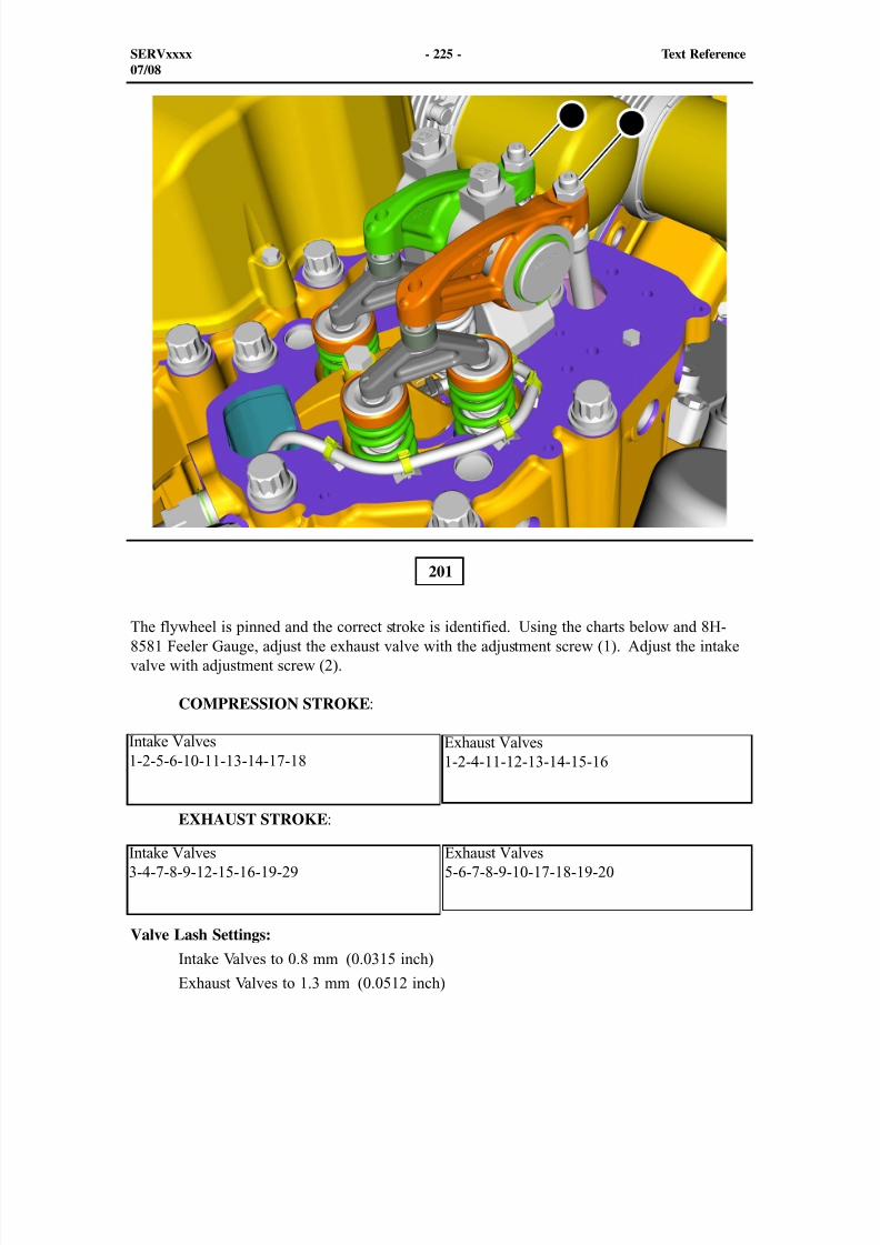
8/9/2019 797F HAA - Meeting Guide.pdf
http://slidepdf.com/reader/full/797f-haa-meeting-guidepdf 240/367
SERVxxxx - 225 - Text Reference07/08
201
The flywheel is pinned and the correct stroke is identified. Using the charts below and 8H-8581 Feeler Gauge, adjust the exhaust valve with the adjustment screw (1). Adjust the intakevalve with adjustment screw (2).
COMPRESSION STROKE :
EXHAUST STROKE :
Valve Lash Settings:
Intake Valves to 0.8 mm (0.0315 inch)
Exhaust Valves to 1.3 mm (0.0512 inch)
Intake Valves1-2-5-6-10-11-13-14-17-18
Exhaust Valves1-2-4-11-12-13-14-15-16
Intake Valves3-4-7-8-9-12-15-16-19-29
Exhaust Valves5-6-7-8-9-10-17-18-19-20
21
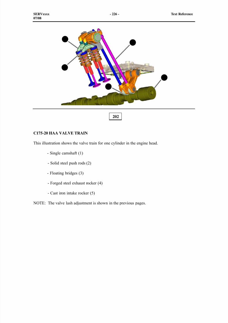
8/9/2019 797F HAA - Meeting Guide.pdf
http://slidepdf.com/reader/full/797f-haa-meeting-guidepdf 241/367
202
C175-20 HAA VALVE TRAIN
This illustration shows the valve train for one cylinder in the engine head.
- Single camshaft (1)
- Solid steel push rods (2)
- Floating bridges (3)
- Forged steel exhaust rocker (4)
- Cast iron intake rocker (5)
NOTE: The valve lash adjustment is shown in the previous pages.
SERVxxxx - 226 - Text Reference07/08
2
3
4
1
5
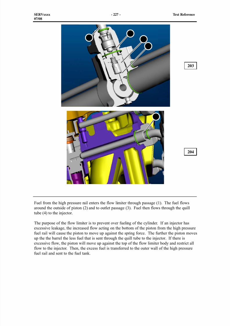
8/9/2019 797F HAA - Meeting Guide.pdf
http://slidepdf.com/reader/full/797f-haa-meeting-guidepdf 242/367
203
SERVxxxx - 227 - Text Reference07/08
204
Fuel from the high pressure rail enters the flow limiter through passage (1). The fuel flowsaround the outside of piston (2) and to outlet passage (3). Fuel then flows through the quill
tube (4) to the injector.
The purpose of the flow limiter is to prevent over fueling of the cylinder. If an injector hasexcessive leakage, the increased flow acting on the bottom of the piston from the high pressurefuel rail will cause the piston to move up against the spring force. The further the piston movesup the the barrel the less fuel that is sent through the quill tube to the injector. If there isexcessive flow, the piston will move up against the top of the flow limiter body and restrict allflow to the injector. Then, the excess fuel is transferred to the outer wall of the high pressurefuel rail and sent to the fuel tank.
32
1
4
4
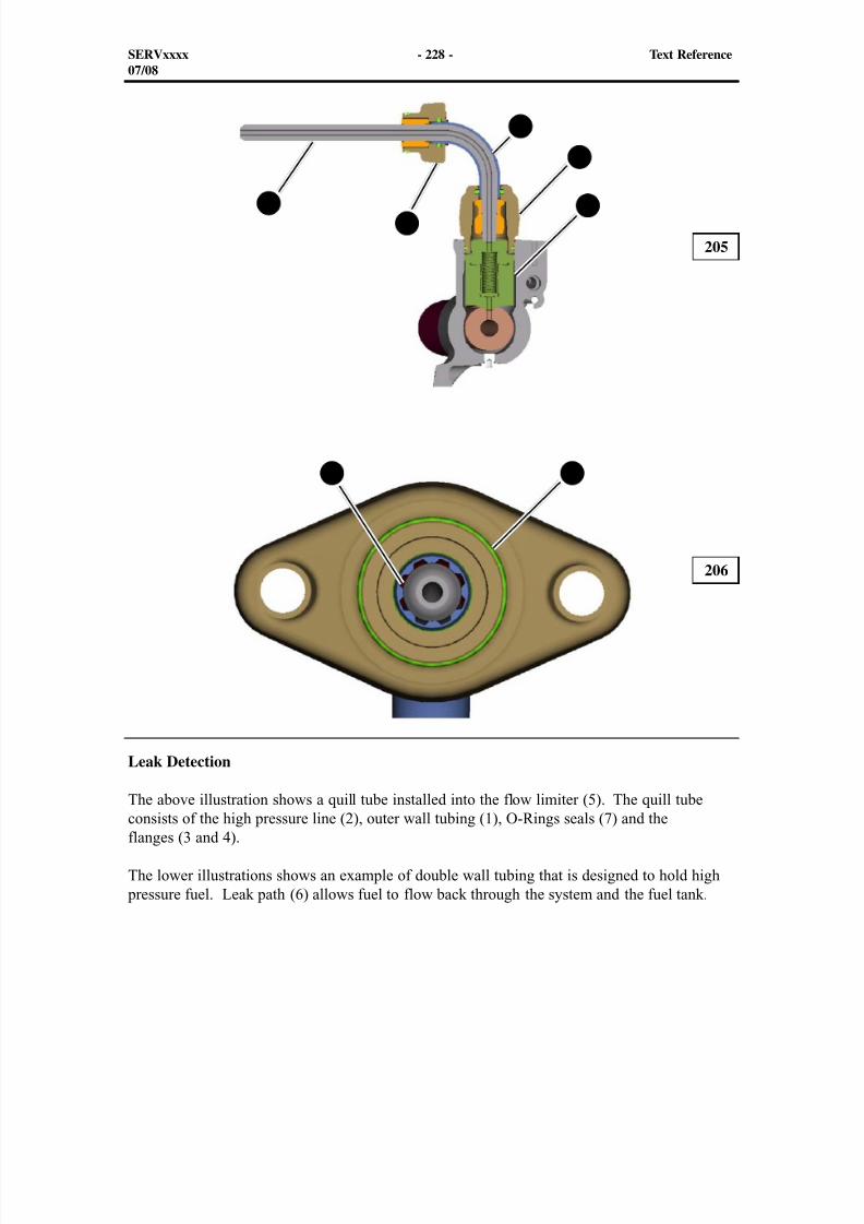
8/9/2019 797F HAA - Meeting Guide.pdf
http://slidepdf.com/reader/full/797f-haa-meeting-guidepdf 243/367
SERVxxxx - 228 - Text Reference07/08
205
206
Leak Detection
The above illustration shows a quill tube installed into the flow limiter (5). The quill tubeconsists of the high pressure line (2), outer wall tubing (1), O-Rings seals (7) and theflanges (3 and 4).
The lower illustrations shows an example of double wall tubing that is designed to hold high pressure fuel. Leak path (6) allows fuel to flow back through the system and the fuel tank.
1
4
53
2
6 7
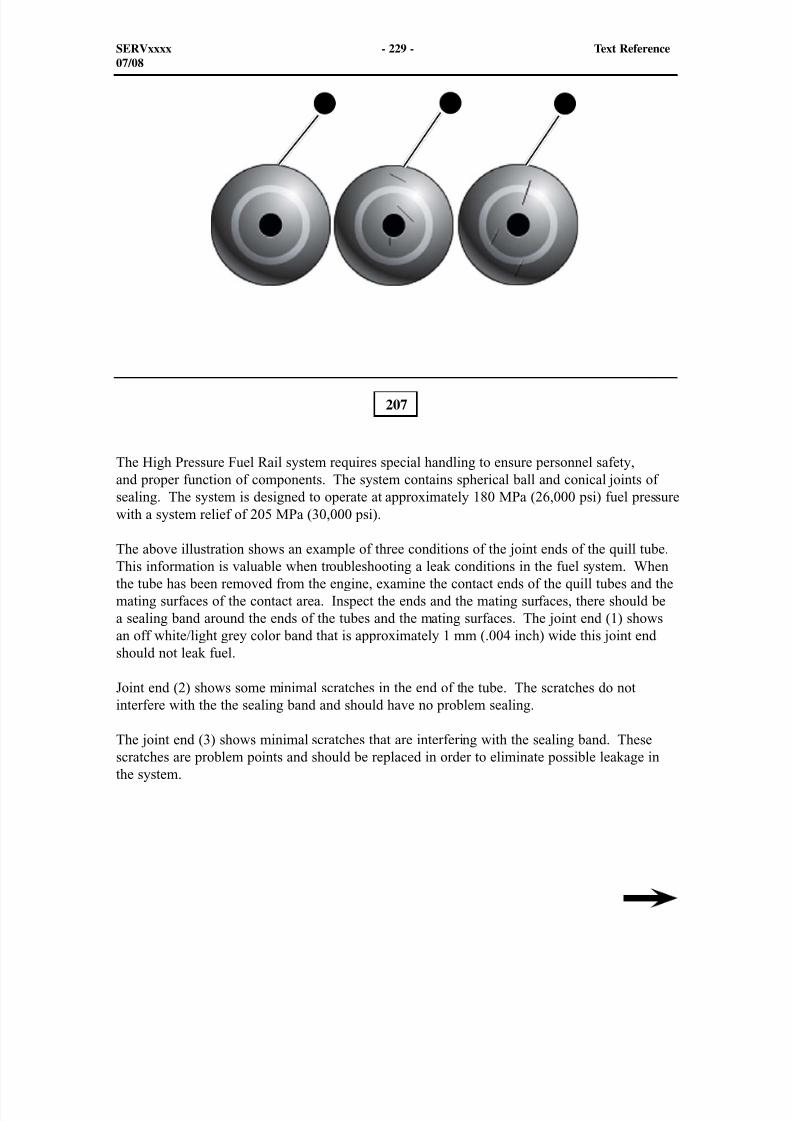
8/9/2019 797F HAA - Meeting Guide.pdf
http://slidepdf.com/reader/full/797f-haa-meeting-guidepdf 244/367
207
The High Pressure Fuel Rail system requires special handling to ensure personnel safety,and proper function of components. The system contains spherical ball and conical joints ofsealing. The system is designed to operate at approximately 180 MPa (26,000 psi) fuel pressurewith a system relief of 205 MPa (30,000 psi).
The above illustration shows an example of three conditions of the joint ends of the quill tube.This information is valuable when troubleshooting a leak conditions in the fuel system. Whenthe tube has been removed from the engine, examine the contact ends of the quill tubes and themating surfaces of the contact area. Inspect the ends and the mating surfaces, there should bea sealing band around the ends of the tubes and the mating surfaces. The joint end (1) showsan off white/light grey color band that is approximately 1 mm (.004 inch) wide this joint endshould not leak fuel.
Joint end (2) shows some minimal scratches in the end of the tube. The scratches do notinterfere with the the sealing band and should have no problem sealing.
The joint end (3) shows minimal scratches that are interfering with the sealing band. Thesescratches are problem points and should be replaced in order to eliminate possible leakage inthe system.
SERVxxxx - 229 - Text Reference07/08
1 2 3

8/9/2019 797F HAA - Meeting Guide.pdf
http://slidepdf.com/reader/full/797f-haa-meeting-guidepdf 245/367
SERVxxxx - 230 - Text Reference07/08
Leaks in the fuel system have been found to be caused by one of the following.
- Improper alignment of the system components causing scratches similar to those shownin the previous illustration.
- Paint flakes or other debris to the sealing surfaces of the conical and spherical joints. - The pressure sensor, adapters, or an O-ring seal
NOTE: When a fuel system leak is positively verified, document the rate of leak,engine hours, any recent service, and other issues with the engine. This informationwill then be used properly troubleshoot a fuel system leak.
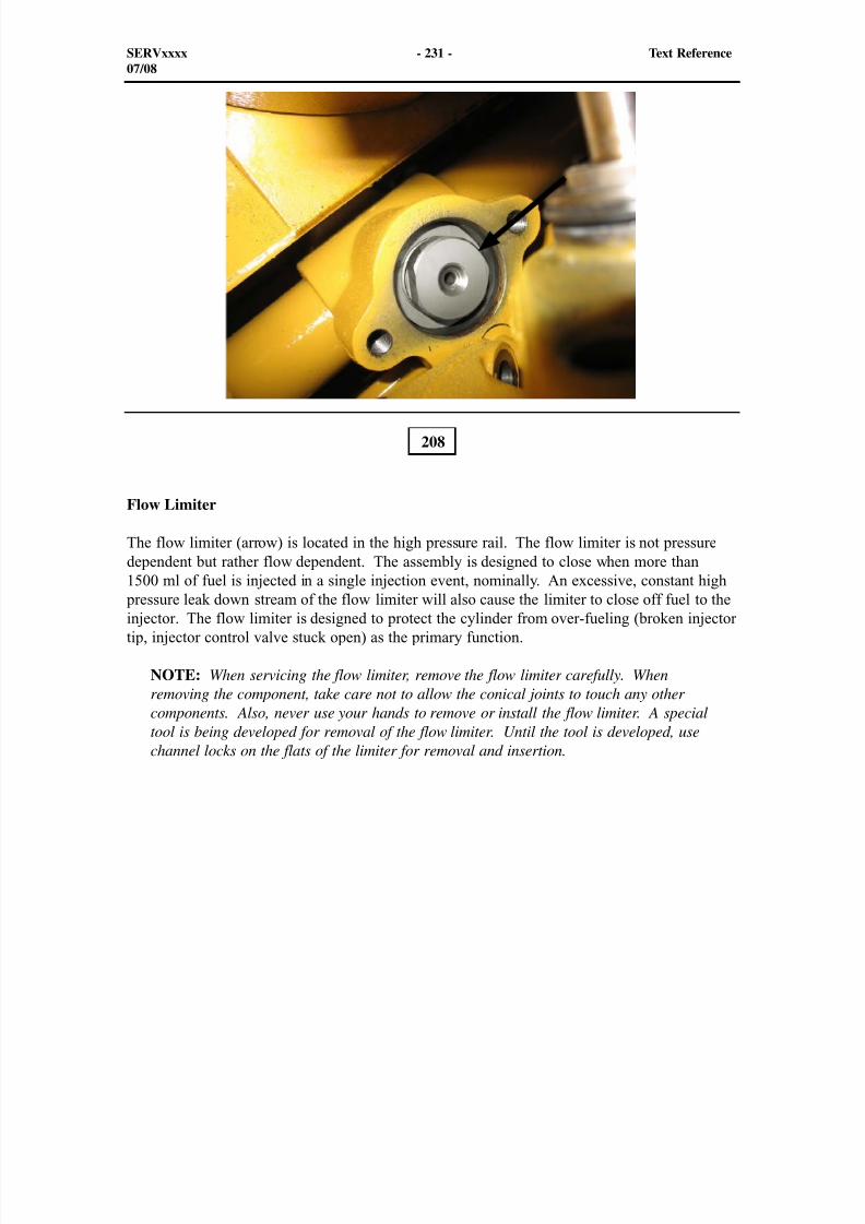
8/9/2019 797F HAA - Meeting Guide.pdf
http://slidepdf.com/reader/full/797f-haa-meeting-guidepdf 246/367
208
Flow Limiter
The flow limiter (arrow) is located in the high pressure rail. The flow limiter is not pressuredependent but rather flow dependent. The assembly is designed to close when more than1500 ml of fuel is injected in a single injection event, nominally. An excessive, constant high
pressure leak down stream of the flow limiter will also cause the limiter to close off fuel to theinjector. The flow limiter is designed to protect the cylinder from over-fueling (broken injectortip, injector control valve stuck open) as the primary function.
NOTE: When servicing the flow limiter, remove the flow limiter carefully. Whenremoving the component, take care not to allow the conical joints to touch any othercomponents. Also, never use your hands to remove or install the flow limiter. A specialtool is being developed for removal of the flow limiter. Until the tool is developed, usechannel locks on the flats of the limiter for removal and insertion.
SERVxxxx - 231 - Text Reference07/08
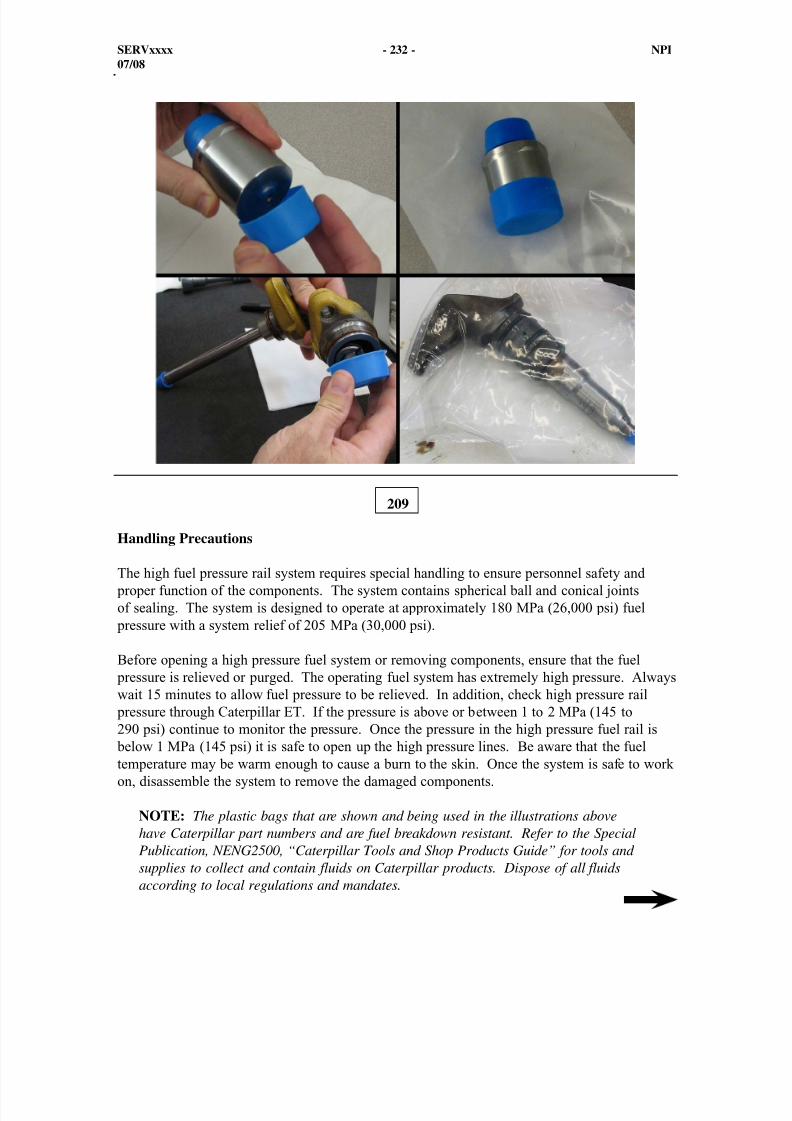
8/9/2019 797F HAA - Meeting Guide.pdf
http://slidepdf.com/reader/full/797f-haa-meeting-guidepdf 247/367
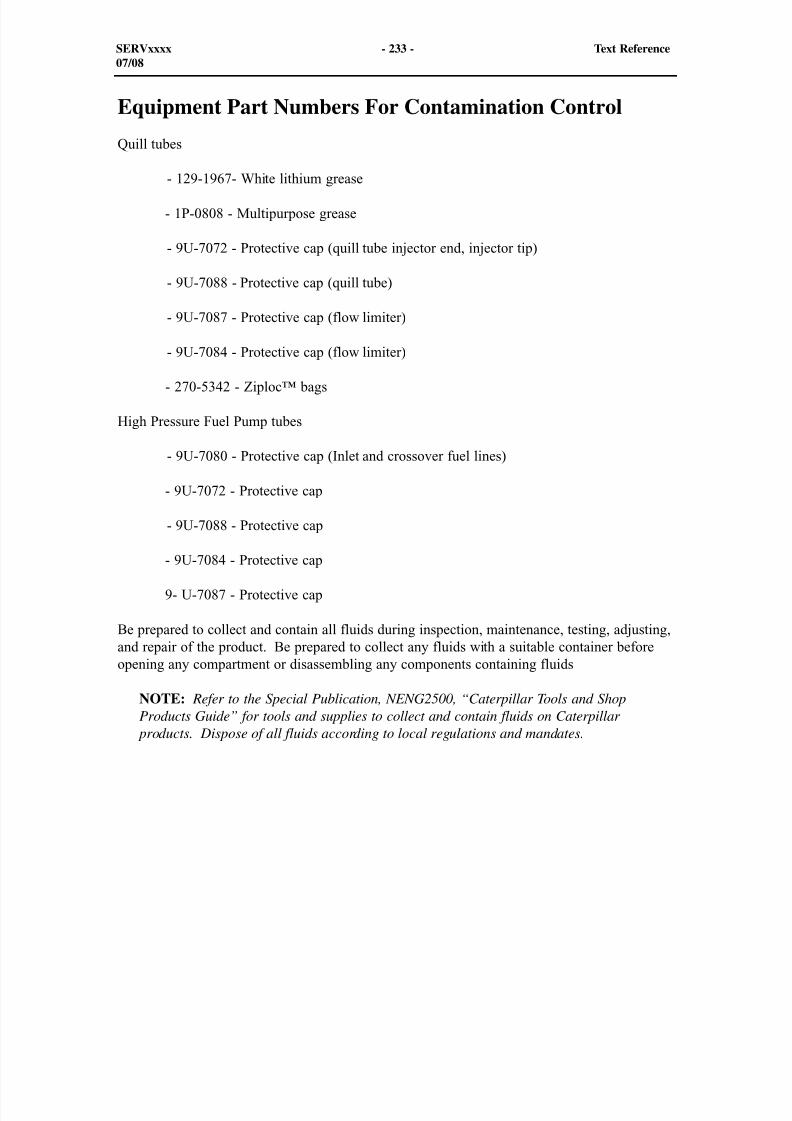
8/9/2019 797F HAA - Meeting Guide.pdf
http://slidepdf.com/reader/full/797f-haa-meeting-guidepdf 248/367
Equipment Part Numbers For Contamination Control
Quill tubes
- 129-1967- White lithium grease
- 1P-0808 - Multipurpose grease
- 9U-7072 - Protective cap (quill tube injector end, injector tip)
- 9U-7088 - Protective cap (quill tube)
- 9U-7087 - Protective cap (flow limiter)
- 9U-7084 - Protective cap (flow limiter)
- 270-5342 - Ziploc™ bags
High Pressure Fuel Pump tubes
- 9U-7080 - Protective cap (Inlet and crossover fuel lines)
- 9U-7072 - Protective cap
- 9U-7088 - Protective cap
- 9U-7084 - Protective cap
9- U-7087 - Protective cap
Be prepared to collect and contain all fluids during inspection, maintenance, testing, adjusting,and repair of the product. Be prepared to collect any fluids with a suitable container beforeopening any compartment or disassembling any components containing fluids
NOTE: Refer to the Special Publication, NENG2500, “Caterpillar Tools and ShopProducts Guide” for tools and supplies to collect and contain fluids on Caterpillar
products. Dispose of all fluids according to local regulations and mandates.
SERVxxxx - 233 - Text Reference07/08
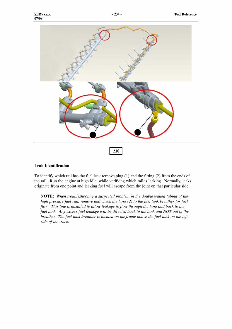
8/9/2019 797F HAA - Meeting Guide.pdf
http://slidepdf.com/reader/full/797f-haa-meeting-guidepdf 249/367
210
Leak Identification
To identify which rail has the fuel leak remove plug (1) and the fitting (2) from the ends ofthe rail. Run the engine at high idle, while verifying which rail is leaking. Normally, leaksoriginate from one point and leaking fuel will escape from the joint on that particular side.
NOTE: When troubleshooting a suspected problem in the double walled tubing of thehigh pressure fuel rail, remove and check the hose (2) to the fuel tank breather for fuel
flow. This line is installed to allow leakage to flow through the hose and back to the fuel tank. Any excess fuel leakage will be directed back to the tank and NOT out of thebreather. The fuel tank breather is located on the frame above the fuel tank on the leftside of the truck.
SERVxxxx - 234 - Text Reference07/08
1 2
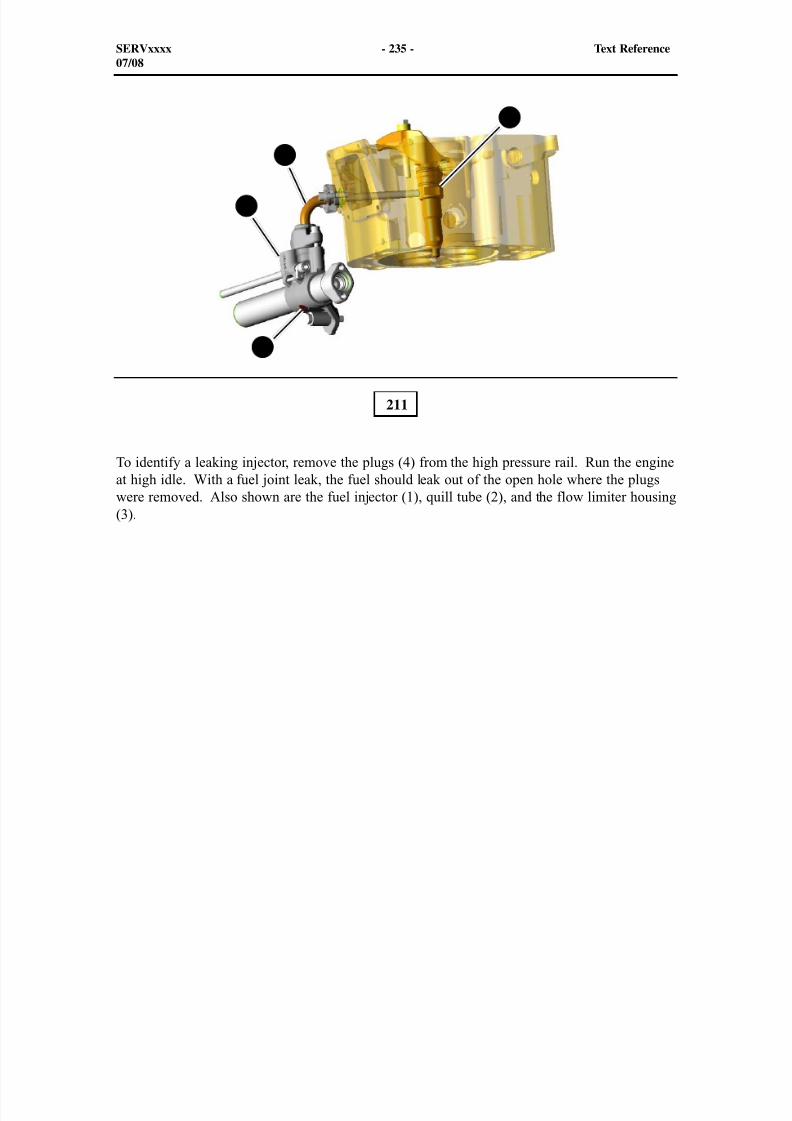
8/9/2019 797F HAA - Meeting Guide.pdf
http://slidepdf.com/reader/full/797f-haa-meeting-guidepdf 250/367
211
To identify a leaking injector, remove the plugs (4) from the high pressure rail. Run the engineat high idle. With a fuel joint leak, the fuel should leak out of the open hole where the plugswere removed. Also shown are the fuel injector (1), quill tube (2), and the flow limiter housing(3).
SERVxxxx - 235 - Text Reference07/08
1
2
3
4
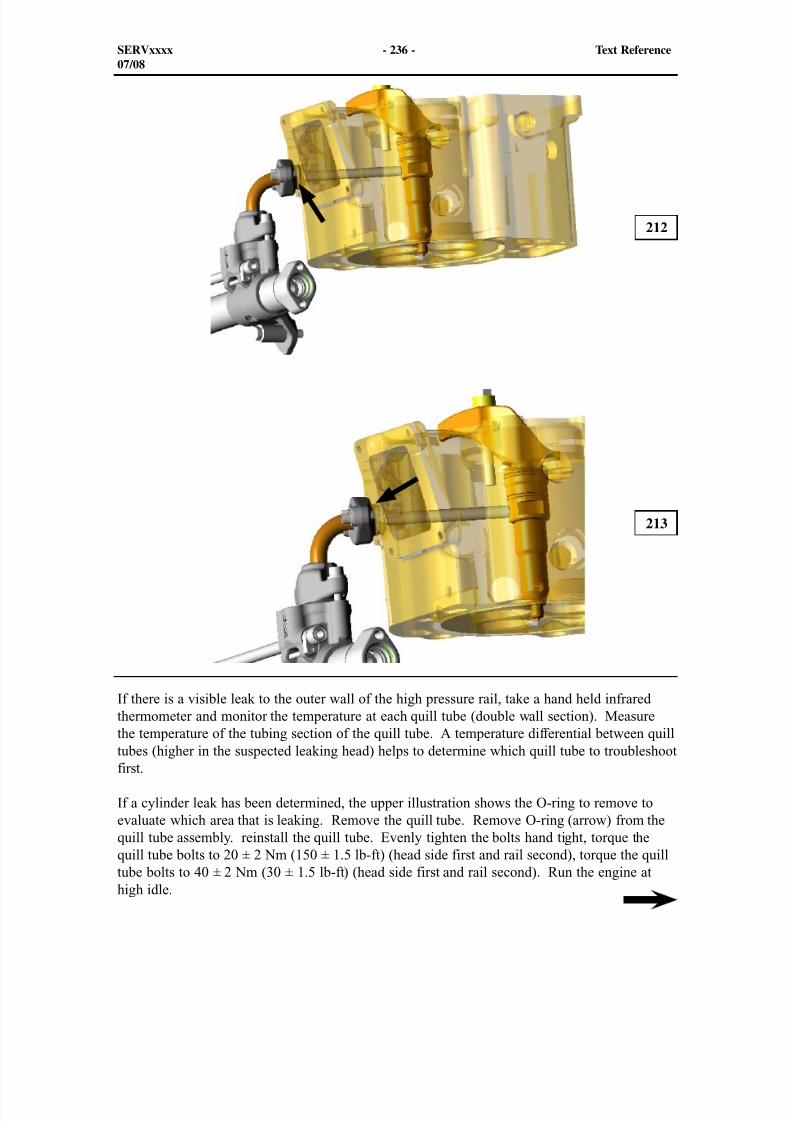
8/9/2019 797F HAA - Meeting Guide.pdf
http://slidepdf.com/reader/full/797f-haa-meeting-guidepdf 251/367
SERVxxxx - 236 - Text Reference07/08
212
213
If there is a visible leak to the outer wall of the high pressure rail, take a hand held infraredthermometer and monitor the temperature at each quill tube (double wall section). Measure
the temperature of the tubing section of the quill tube. A temperature differential between quilltubes (higher in the suspected leaking head) helps to determine which quill tube to troubleshootfirst.
If a cylinder leak has been determined, the upper illustration shows the O-ring to remove toevaluate which area that is leaking. Remove the quill tube. Remove O-ring (arrow) from thequill tube assembly. reinstall the quill tube. Evenly tighten the bolts hand tight, torque thequill tube bolts to 20 ± 2 Nm (150 ± 1.5 lb-ft) (head side first and rail second), torque the quilltube bolts to 40 ± 2 Nm (30 ± 1.5 lb-ft) (head side first and rail second). Run the engine athigh idle.
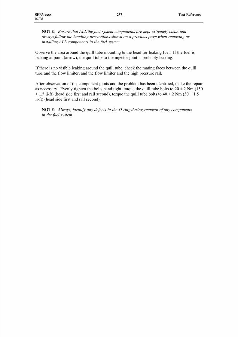
8/9/2019 797F HAA - Meeting Guide.pdf
http://slidepdf.com/reader/full/797f-haa-meeting-guidepdf 252/367
NOTE: Ensure that ALL the fuel system components are kept extremely clean andalways follow the handling precautions shown on a previous page when removing orinstalling ALL components in the fuel system.
Observe the area around the quill tube mounting to the head for leaking fuel. If the fuel isleaking at point (arrow), the quill tube to the injector joint is probably leaking.
If there is no visible leaking around the quill tube, check the mating faces between the quilltube and the flow limiter, and the flow limiter and the high pressure rail.
After observation of the component joints and the problem has been identified, make the repairsas necessary. Evenly tighten the bolts hand tight, torque the quill tube bolts to 20 ± 2 Nm (150± 1.5 li-ft) (head side first and rail second), torque the quill tube bolts to 40 ± 2 Nm (30 ± 1.5li-ft) (head side first and rail second).
NOTE: Always, identify any defects in the O-ring during removal of any componentsin the fuel system.
SERVxxxx - 237 - Text Reference07/08
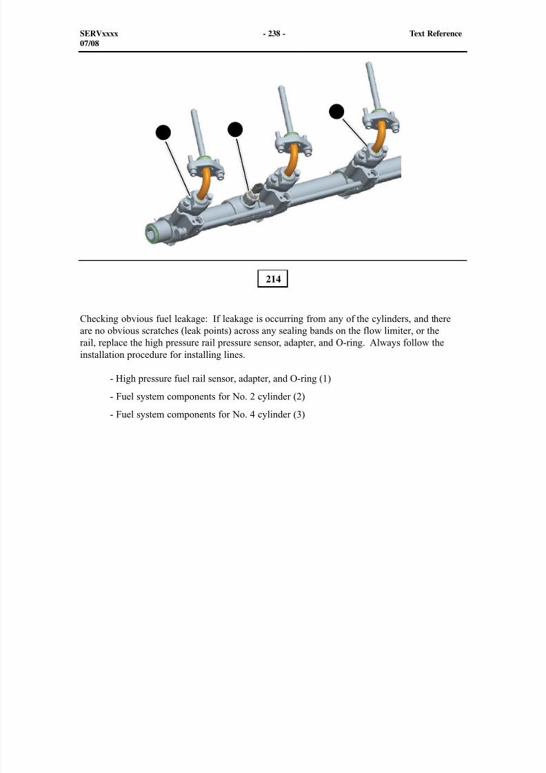
8/9/2019 797F HAA - Meeting Guide.pdf
http://slidepdf.com/reader/full/797f-haa-meeting-guidepdf 253/367
SERVxxxx - 238 - Text Reference07/08
214
Checking obvious fuel leakage: If leakage is occurring from any of the cylinders, and thereare no obvious scratches (leak points) across any sealing bands on the flow limiter, or therail, replace the high pressure rail pressure sensor, adapter, and O-ring. Always follow theinstallation procedure for installing lines.
- High pressure fuel rail sensor, adapter, and O-ring (1)- Fuel system components for No. 2 cylinder (2)
- Fuel system components for No. 4 cylinder (3)
1
3
2
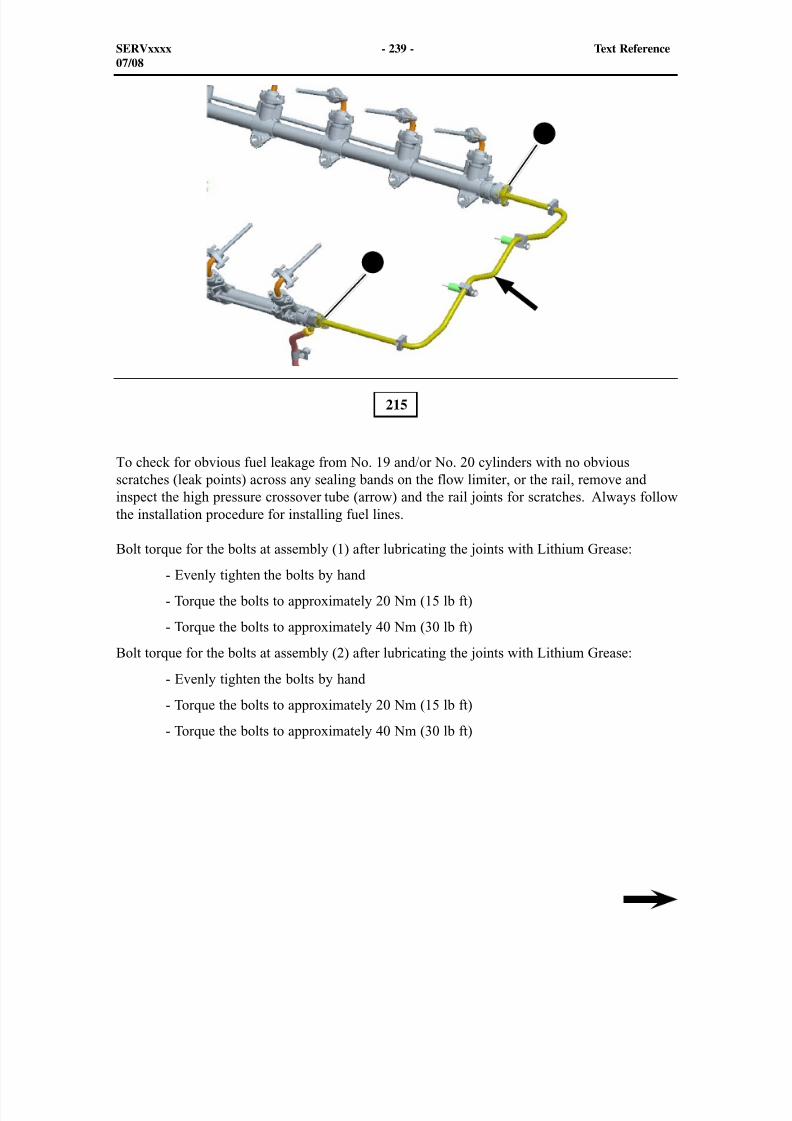
8/9/2019 797F HAA - Meeting Guide.pdf
http://slidepdf.com/reader/full/797f-haa-meeting-guidepdf 254/367
215
To check for obvious fuel leakage from No. 19 and/or No. 20 cylinders with no obviousscratches (leak points) across any sealing bands on the flow limiter, or the rail, remove andinspect the high pressure crossover tube (arrow) and the rail joints for scratches. Always followthe installation procedure for installing fuel lines.
Bolt torque for the bolts at assembly (1) after lubricating the joints with Lithium Grease: - Evenly tighten the bolts by hand
- Torque the bolts to approximately 20 Nm (15 lb ft)
- Torque the bolts to approximately 40 Nm (30 lb ft)
Bolt torque for the bolts at assembly (2) after lubricating the joints with Lithium Grease:
- Evenly tighten the bolts by hand
- Torque the bolts to approximately 20 Nm (15 lb ft)
- Torque the bolts to approximately 40 Nm (30 lb ft)
SERVxxxx - 239 - Text Reference07/08
1
2
8/9/2019 797F HAA - Meeting Guide.pdf
http://slidepdf.com/reader/full/797f-haa-meeting-guidepdf 255/367
SERVxxxx - 240 - Text Reference07/08
216
To check for obvious fuel leakage from No. 1 cylinder with no obvious scratches (leak points)across any sealing bands on the flow limiter, or the rail. Remove and inspect tube (1), and tube(2) that is connected to the high pressure pump. Also, check the sealing surfaces on the high
pressure rail for scratches. Replace any tubes with questionable sealing surfaces.
When assembling the the fuel system components, always keep all the components clean andfollow the torque procedures when connecting the tubes.
Bolt Torque for joint (3) assembly after lubrication the with Lithium Grease:
- Evenly tighten the bolts by hand
- Torque the bolts to approximately 20 Nm (15 li ft)
- Torque the bolts to approximately 40 Nm (30 li ft)
Bolt Torque for joint (4) assembly after lubrication with Lithium Grease. With tube (1)disconnected from block (7) torque the bolts:
- Evenly tighten the bolts by hand
-Torque the bolts to approximately 10 Nm (7.5 li ft)
7
5
4
12
3
6

8/9/2019 797F HAA - Meeting Guide.pdf
http://slidepdf.com/reader/full/797f-haa-meeting-guidepdf 256/367
SERVxxxx - 241 - Text Reference07/08
Bolt Torque for joint (6) assembly after lubrication with Lithium Grease.
- Evenly tighten the bolts by hand
- Torque the bolts to approximately 20 Nm (15 li ft)
- Torque the bolts to approximately 40 Nm (30 li ft)Bolt Torque for joint (5) assembly after lubrication with Lithium Grease.
- Evenly tighten the bolts by hand
- Torque the bolts to approximately 20 Nm (15 li ft)
- Torque the bolts to approximately 40 Nm (30 li ft)
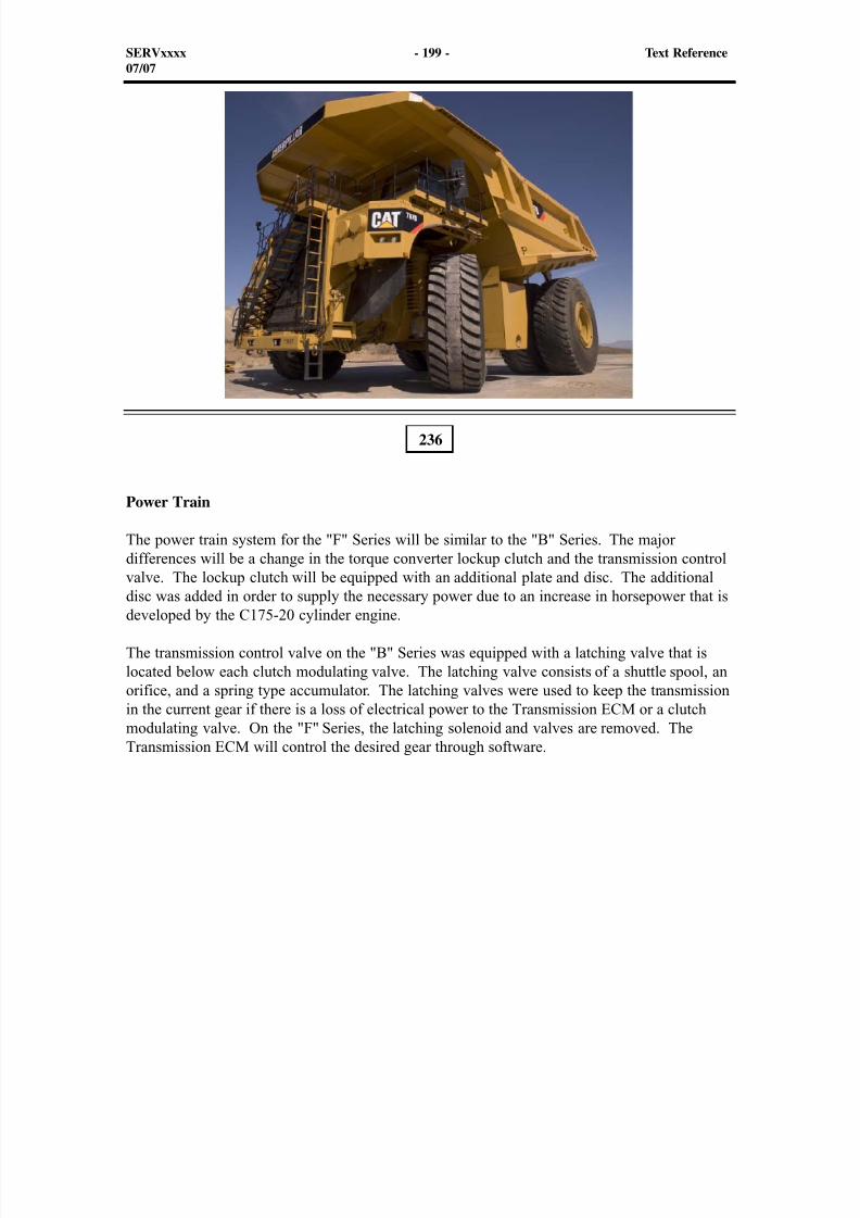
8/9/2019 797F HAA - Meeting Guide.pdf
http://slidepdf.com/reader/full/797f-haa-meeting-guidepdf 257/367
Power Train
The power train system for the "F" Series will be similar to the "B" Series. The majordifferences will be a change in the torque converter lockup clutch and the transmission controlvalve. The lockup clutch will be equipped with an additional plate and disc. The additional
disc was added in order to supply the necessary power due to an increase in horsepower that isdeveloped by the C175-20 cylinder engine.
The transmission control valve on the "B" Series was equipped with a latching valve that islocated below each clutch modulating valve. The latching valve consists of a shuttle spool, anorifice, and a spring type accumulator. The latching valves were used to keep the transmissionin the current gear if there is a loss of electrical power to the Transmission ECM or a clutchmodulating valve. On the "F" Series, the latching solenoid and valves are removed. TheTransmission ECM will control the desired gear through software.
236
SERVxxxx - 199 - Text Reference07/07
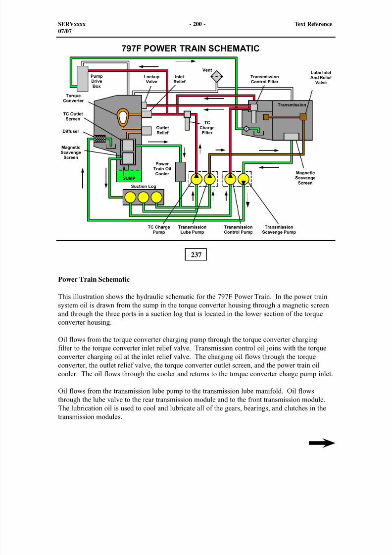
8/9/2019 797F HAA - Meeting Guide.pdf
http://slidepdf.com/reader/full/797f-haa-meeting-guidepdf 258/367
237
Power Train Schematic
This illustration shows the hydraulic schematic for the 797F Power Train. In the power trainsystem oil is drawn from the sump in the torque converter housing through a magnetic screenand through the three ports in a suction log that is located in the lower section of the torqueconverter housing.
Oil flows from the torque converter charging pump through the torque converter chargingfilter to the torque converter inlet relief valve. Transmission control oil joins with the torqueconverter charging oil at the inlet relief valve. The charging oil flows through the torqueconverter, the outlet relief valve, the torque converter outlet screen, and the power train oilcooler. The oil flows through the cooler and returns to the torque converter charge pump inlet.
Oil flows from the transmission lube pump to the transmission lube manifold. Oil flowsthrough the lube valve to the rear transmission module and to the front transmission module.The lubrication oil is used to cool and lubricate all of the gears, bearings, and clutches in thetransmission modules.
SERVxxxx - 200 - Text Reference07/07

8/9/2019 797F HAA - Meeting Guide.pdf
http://slidepdf.com/reader/full/797f-haa-meeting-guidepdf 259/367
Oil flows from the transmission control pump to the transmission control filter. Oil flowsthrough the control filter to the transmission control valves. When the control valve solenoidsare energized by the Transmission ECM, oil flows to the transmission clutches.
Oil also flows from the top of the transmission control filter to the torque converter lockupvalve. Transmission control oil is used by the lockup clutch in order to provide torqueconverter lockup when the requirements are met.
Transmission control and lubrication oil that falls to the bottom of the transmission case isdrawn through the magnetic scavenge screen (in the transmission housing) by the transmissionscavenge pump. Then, that oil is directed through a diffuser that is located within the torqueconverter housing. The scavenge oil flows to the torque converter sump.
SERVxxxx - 201 - Text Reference07/07
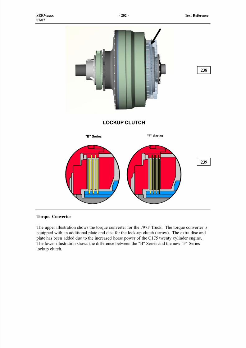
8/9/2019 797F HAA - Meeting Guide.pdf
http://slidepdf.com/reader/full/797f-haa-meeting-guidepdf 260/367
Torque Converter
The upper illustration shows the torque converter for the 797F Truck. The torque converter isequipped with an additional plate and disc for the lock-up clutch (arrow). The extra disc and plate has been added due to the increased horse power of the C175 twenty cylinder engine.The lower illustration shows the difference between the "B" Series and the new "F" Serieslockup clutch.
238
239
SERVxxxx - 202 - Text Reference07/07
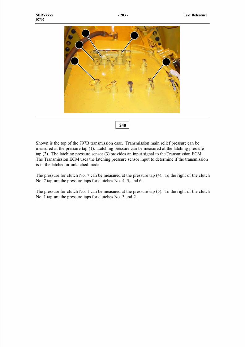
8/9/2019 797F HAA - Meeting Guide.pdf
http://slidepdf.com/reader/full/797f-haa-meeting-guidepdf 261/367
1
23
4
5
Shown is the top of the 797B transmission case. Transmission main relief pressure can bemeasured at the pressure tap (1). Latching pressure can be measured at the latching pressuretap (2). The latching pressure sensor (3) provides an input signal to the Transmission ECM.The Transmission ECM uses the latching pressure sensor input to determine if the transmissionis in the latched or unlatched mode.
The pressure for clutch No. 7 can be measured at the pressure tap (4). To the right of the clutch No. 7 tap are the pressure taps for clutches No. 4, 5, and 6.
The pressure for clutch No. 1 can be measured at the pressure tap (5). To the right of the clutch No. 1 tap are the pressure taps for clutches No. 3 and 2.
240
SERVxxxx - 203 - Text Reference07/07
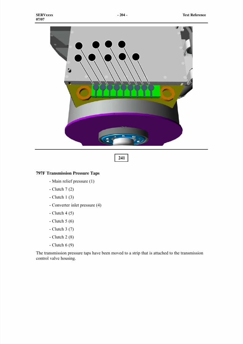
8/9/2019 797F HAA - Meeting Guide.pdf
http://slidepdf.com/reader/full/797f-haa-meeting-guidepdf 262/367
241
797F Transmission Pressure Taps
- Main relief pressure (1)
- Clutch 7 (2)
- Clutch 1 (3)
- Converter inlet pressure (4)
- Clutch 4 (5)
- Clutch 5 (6)
- Clutch 3 (7)
- Clutch 2 (8)
- Clutch 6 (9)
The transmission pressure taps have been moved to a strip that is attached to the transmissioncontrol valve housing.
SERVxxxx - 204 - Text Reference07/07
1
2
3
4
5
6
7
8
9
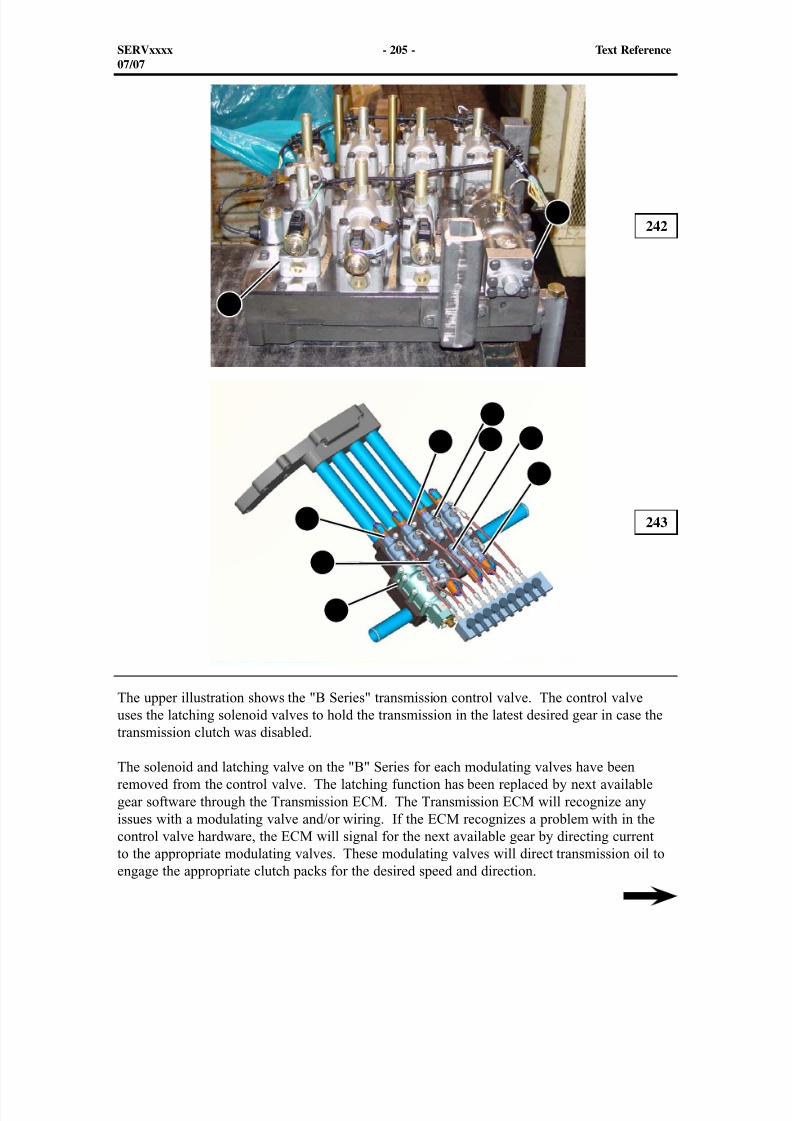
8/9/2019 797F HAA - Meeting Guide.pdf
http://slidepdf.com/reader/full/797f-haa-meeting-guidepdf 263/367
The upper illustration shows the "B Series" transmission control valve. The control valveuses the latching solenoid valves to hold the transmission in the latest desired gear in case the
transmission clutch was disabled.
The solenoid and latching valve on the "B" Series for each modulating valves have beenremoved from the control valve. The latching function has been replaced by next availablegear software through the Transmission ECM. The Transmission ECM will recognize anyissues with a modulating valve and/or wiring. If the ECM recognizes a problem with in thecontrol valve hardware, the ECM will signal for the next available gear by directing currentto the appropriate modulating valves. These modulating valves will direct transmission oil toengage the appropriate clutch packs for the desired speed and direction.
242
243
SERVxxxx - 205 - Text Reference07/07
1
2
1
2
3 4
5
6
7
8
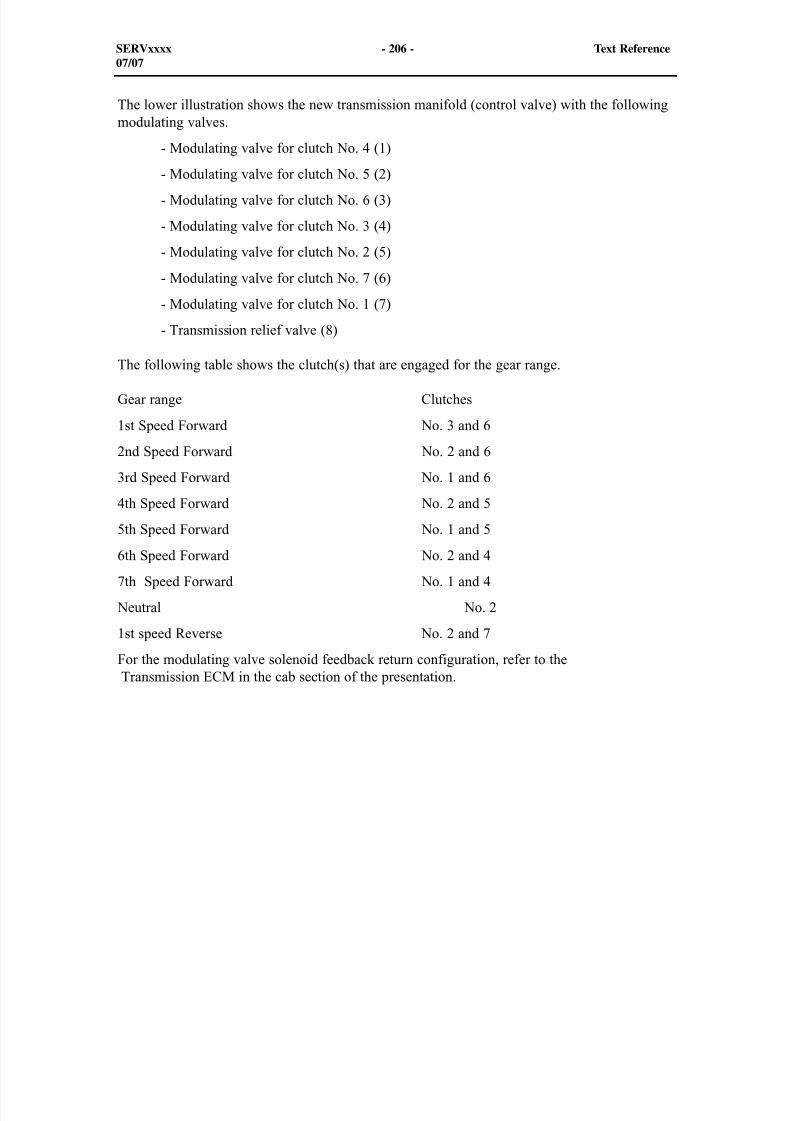
8/9/2019 797F HAA - Meeting Guide.pdf
http://slidepdf.com/reader/full/797f-haa-meeting-guidepdf 264/367
The lower illustration shows the new transmission manifold (control valve) with the followingmodulating valves.
- Modulating valve for clutch No. 4 (1)
- Modulating valve for clutch No. 5 (2)
- Modulating valve for clutch No. 6 (3)
- Modulating valve for clutch No. 3 (4)
- Modulating valve for clutch No. 2 (5)
- Modulating valve for clutch No. 7 (6)
- Modulating valve for clutch No. 1 (7)
- Transmission relief valve (8)
The following table shows the clutch(s) that are engaged for the gear range.
Gear range Clutches
1st Speed Forward No. 3 and 6
2nd Speed Forward No. 2 and 6
3rd Speed Forward No. 1 and 6
4th Speed Forward No. 2 and 5
5th Speed Forward No. 1 and 5
6th Speed Forward No. 2 and 4
7th Speed Forward No. 1 and 4
Neutral No. 2
1st speed Reverse No. 2 and 7
For the modulating valve solenoid feedback return configuration, refer to the Transmission ECM in the cab section of the presentation.
SERVxxxx - 206 - Text Reference07/07
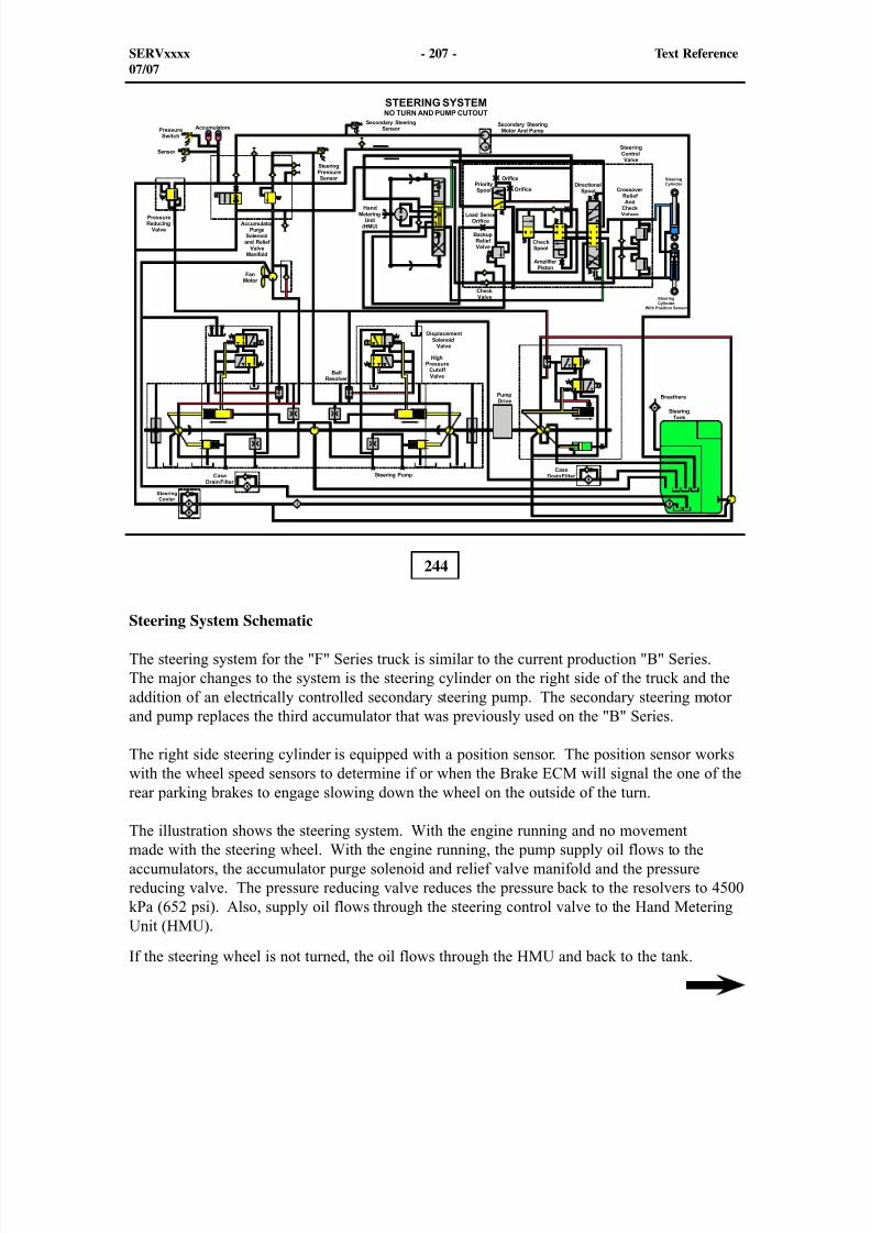
8/9/2019 797F HAA - Meeting Guide.pdf
http://slidepdf.com/reader/full/797f-haa-meeting-guidepdf 265/367
244
Steering System Schematic
The steering system for the "F" Series truck is similar to the current production "B" Series.The major changes to the system is the steering cylinder on the right side of the truck and theaddition of an electrically controlled secondary steering pump. The secondary steering motorand pump replaces the third accumulator that was previously used on the "B" Series.
The right side steering cylinder is equipped with a position sensor. The position sensor workswith the wheel speed sensors to determine if or when the Brake ECM will signal the one of therear parking brakes to engage slowing down the wheel on the outside of the turn.
The illustration shows the steering system. With the engine running and no movementmade with the steering wheel. With the engine running, the pump supply oil flows to theaccumulators, the accumulator purge solenoid and relief valve manifold and the pressurereducing valve. The pressure reducing valve reduces the pressure back to the resolvers to 4500kPa (652 psi). Also, supply oil flows through the steering control valve to the Hand MeteringUnit (HMU).
If the steering wheel is not turned, the oil flows through the HMU and back to the tank.
SERVxxxx - 207 - Text Reference07/07

8/9/2019 797F HAA - Meeting Guide.pdf
http://slidepdf.com/reader/full/797f-haa-meeting-guidepdf 266/367
Allowing oil to circulate through the HMU while the steering wheel is stationary provides a"thermal purge" condition, which maintains a temperature differential of less than 28°C (50°F)
between the HMU and the tank. This "thermal purge" prevents thermal seizure of the HMU(sticking steering wheel).
Oil on both sides of the pistons within the steering cylinders have trapped oil. This oil will be blocked until the steering wheel is moved and a pilot signal is induced at one side or the otherof the directional spool.
SERVxxxx - 208 - Text Reference07/07

8/9/2019 797F HAA - Meeting Guide.pdf
http://slidepdf.com/reader/full/797f-haa-meeting-guidepdf 267/367
Steering Pump
The steering pump is part of a double piston pump group. The steering and fan pump ismounted on the front of the pump drive. The pump drive is locate on the inside of the rightframe near the torque converter. The pump drive is driven by a drive shaft from the engine.This arrangement is similar on both series trucks
The steering pump operates only when the engine is running and provides the necessary flowof oil to the accumulators for steering system operation. The Chassis ECM controls the flow ofoil from the steering pump by the controlling the amount of current that is driving the solenoidvalve.
NOTE: The upper illustration shows the "B" Series steering and fan pump. The lowerillustration shows the "F" Series steering and fan pump.
245
246
SERVxxxx - 209 - Text Reference07/07
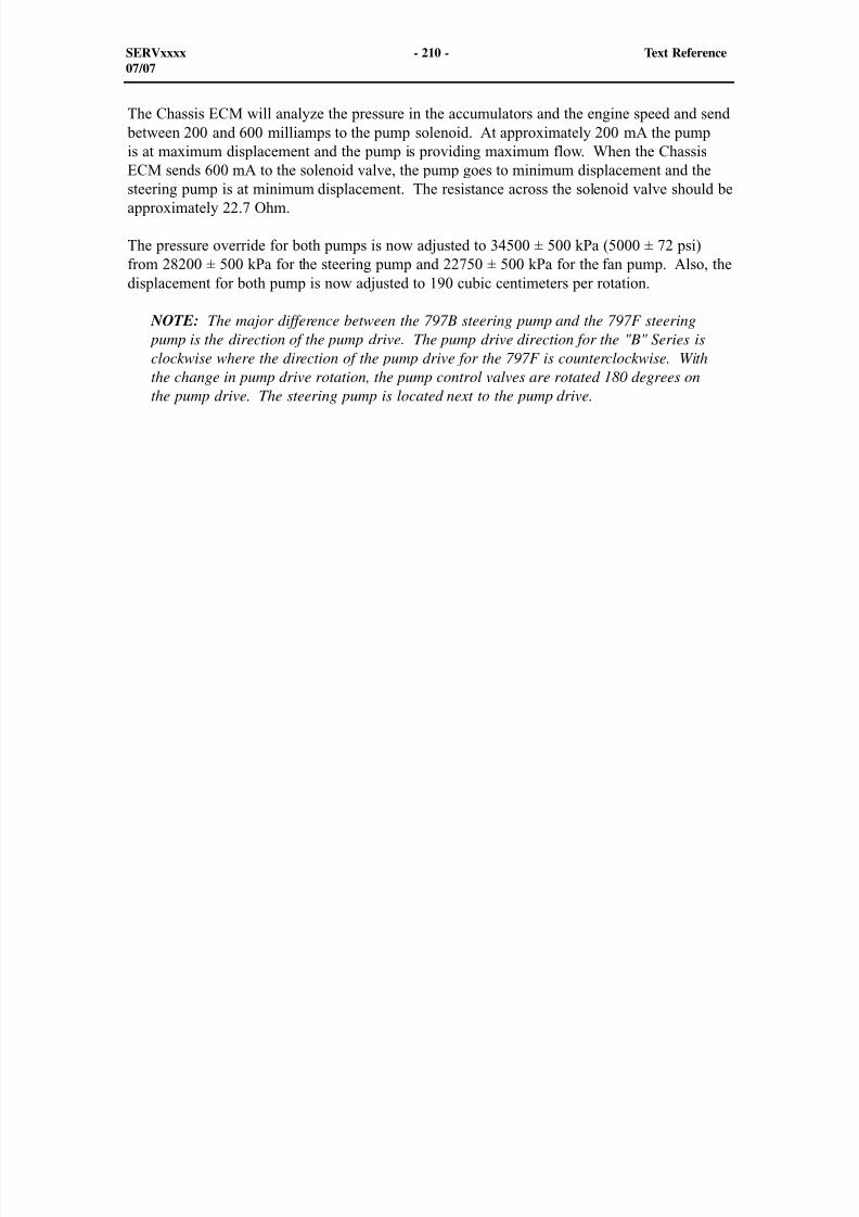
8/9/2019 797F HAA - Meeting Guide.pdf
http://slidepdf.com/reader/full/797f-haa-meeting-guidepdf 268/367
The Chassis ECM will analyze the pressure in the accumulators and the engine speed and send between 200 and 600 milliamps to the pump solenoid. At approximately 200 mA the pumpis at maximum displacement and the pump is providing maximum flow. When the ChassisECM sends 600 mA to the solenoid valve, the pump goes to minimum displacement and thesteering pump is at minimum displacement. The resistance across the solenoid valve should beapproximately 22.7 Ohm.
The pressure override for both pumps is now adjusted to 34500 ± 500 kPa (5000 ± 72 psi)from 28200 ± 500 kPa for the steering pump and 22750 ± 500 kPa for the fan pump. Also, thedisplacement for both pump is now adjusted to 190 cubic centimeters per rotation.
NOTE: The major difference between the 797B steering pump and the 797F steering pump is the direction of the pump drive. The pump drive direction for the "B" Series isclockwise where the direction of the pump drive for the 797F is counterclockwise. Withthe change in pump drive rotation, the pump control valves are rotated 180 degrees on
the pump drive. The steering pump is located next to the pump drive.
SERVxxxx - 210 - Text Reference07/07
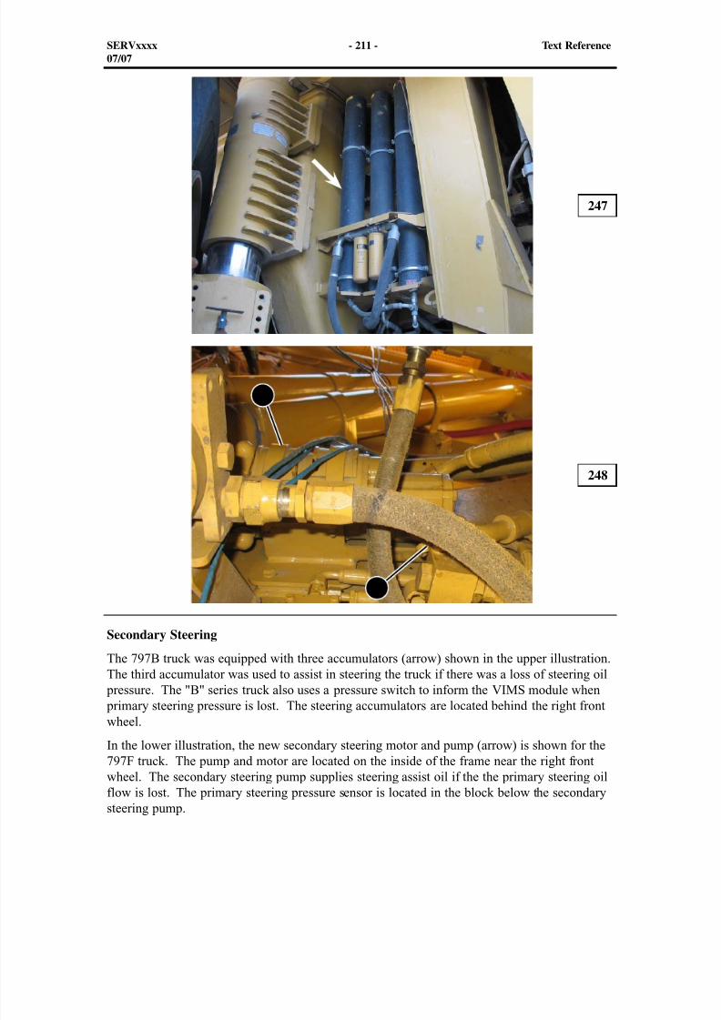
8/9/2019 797F HAA - Meeting Guide.pdf
http://slidepdf.com/reader/full/797f-haa-meeting-guidepdf 269/367
Secondary Steering
The 797B truck was equipped with three accumulators (arrow) shown in the upper illustration.The third accumulator was used to assist in steering the truck if there was a loss of steering oil
pressure. The "B" series truck also uses a pressure switch to inform the VIMS module when primary steering pressure is lost. The steering accumulators are located behind the right frontwheel.
In the lower illustration, the new secondary steering motor and pump (arrow) is shown for the797F truck. The pump and motor are located on the inside of the frame near the right frontwheel. The secondary steering pump supplies steering assist oil if the the primary steering oilflow is lost. The primary steering pressure sensor is located in the block below the secondarysteering pump.
247
248
SERVxxxx - 211 - Text Reference07/07
1
2
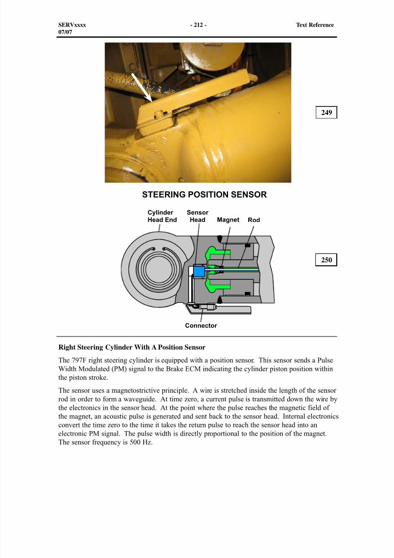
8/9/2019 797F HAA - Meeting Guide.pdf
http://slidepdf.com/reader/full/797f-haa-meeting-guidepdf 270/367
Right Steering Cylinder With A Position Sensor
The 797F right steering cylinder is equipped with a position sensor. This sensor sends a PulseWidth Modulated (PM) signal to the Brake ECM indicating the cylinder piston position withinthe piston stroke.
The sensor uses a magnetostrictive principle. A wire is stretched inside the length of the sensorrod in order to form a waveguide. At time zero, a current pulse is transmitted down the wire bythe electronics in the sensor head. At the point where the pulse reaches the magnetic field ofthe magnet, an acoustic pulse is generated and sent back to the sensor head. Internal electronicsconvert the time zero to the time it takes the return pulse to reach the sensor head into anelectronic PM signal. The pulse width is directly proportional to the position of the magnet.The sensor frequency is 500 Hz.
249
250
SERVxxxx - 212 - Text Reference07/07

8/9/2019 797F HAA - Meeting Guide.pdf
http://slidepdf.com/reader/full/797f-haa-meeting-guidepdf 271/367
The following is a list of the Diagnostic Codes for the steering cylinder position sensor. This position sensor Diagnostic Codes are activated through the Brake ECM.
CID - 2201 - FMI 03 Right Steering Cylinder Position Sensor - Voltage above normal
CID - 2201 - FMI 04 Right Steering Cylinder Position Sensor - Voltage below normal
CID - 2201- FMI 08 Right Steering Cylinder Position Sensor - Abnormal frequency, pulse width, or period
CID - 2201- FMI 13 Right Steering Cylinder Position Sensor - Out of calibration
SERVxxxx - 213 - Text Reference01/06
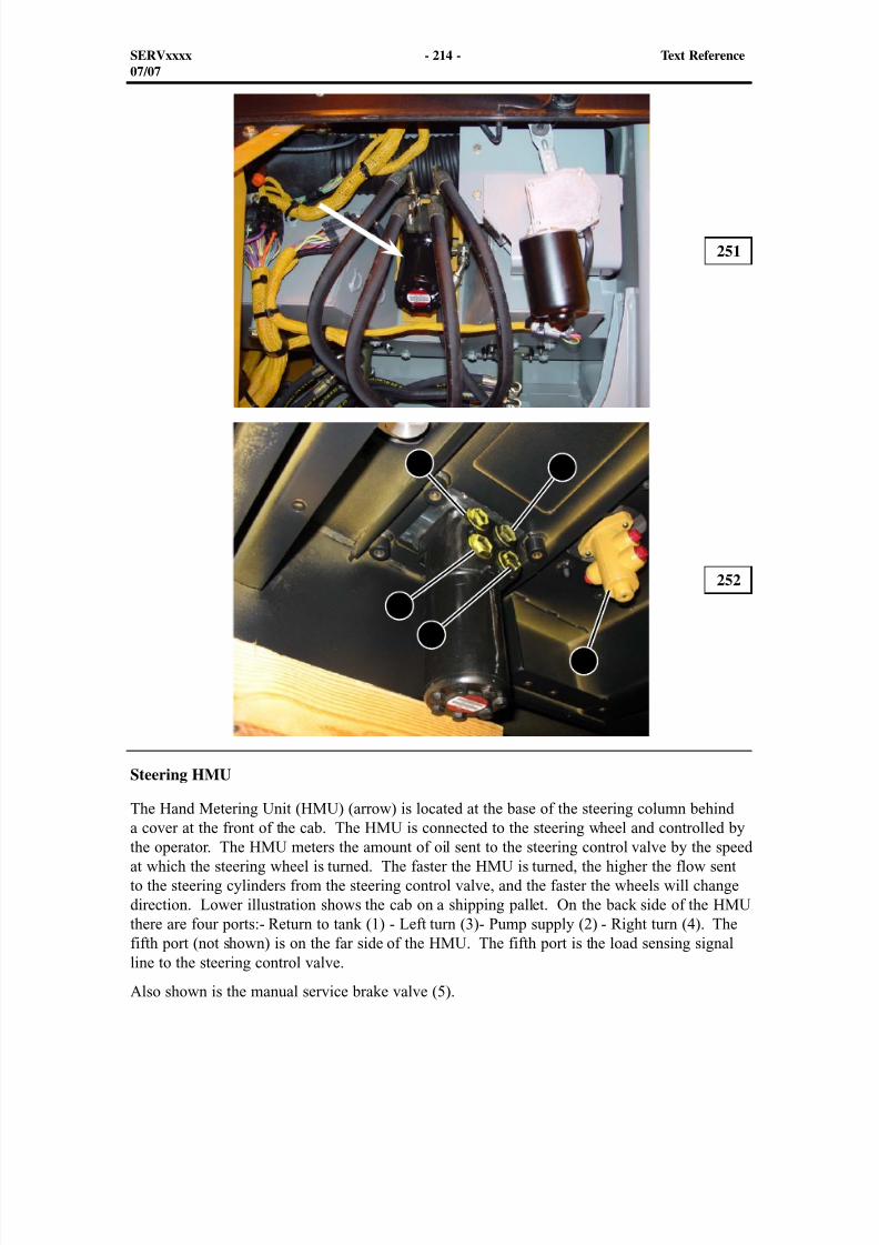
8/9/2019 797F HAA - Meeting Guide.pdf
http://slidepdf.com/reader/full/797f-haa-meeting-guidepdf 272/367
Steering HMU
The Hand Metering Unit (HMU) (arrow) is located at the base of the steering column behinda cover at the front of the cab. The HMU is connected to the steering wheel and controlled bythe operator. The HMU meters the amount of oil sent to the steering control valve by the speedat which the steering wheel is turned. The faster the HMU is turned, the higher the flow sentto the steering cylinders from the steering control valve, and the faster the wheels will changedirection. Lower illustration shows the cab on a shipping pallet. On the back side of the HMUthere are four ports:- Return to tank (1) - Left turn (3)- Pump supply (2) - Right turn (4). Thefifth port (not shown) is on the far side of the HMU. The fifth port is the load sensing signalline to the steering control valve.
Also shown is the manual service brake valve (5).
251
252
SERVxxxx - 214 - Text Reference07/07
1
2
3
4
5
8/9/2019 797F HAA - Meeting Guide.pdf
http://slidepdf.com/reader/full/797f-haa-meeting-guidepdf 273/367
BRAKE SYSTEM
Two separate brake systems are used on the 797F trucks. The two brake systems are: the parking brake system and the service/retarder brake system. The operation of the brake systemfor "F" Series is similar to the "B" Series. The major difference is the "F" Series has one
chassis brake valve compared to a two section chassis brake valve on the 797B truck.
The parking brakes are spring engaged and hydraulically released. The service/parking/retarder brakes are engaged hydraulically and spring released.
Diagnostic Codes concerning the Brake ECM and the braking system will be MID 74 unlessotherwise noted in the presentation.
253
SERVxxxx - 215 - Text Reference07/07

8/9/2019 797F HAA - Meeting Guide.pdf
http://slidepdf.com/reader/full/797f-haa-meeting-guidepdf 274/367
254
Braking System Schematic
The above illustration shows the pump drive rotating the pump group, and the brake systemwith the new chassis brake valve installed. This illustration shows the parking brake engagedand the accumulators are charged. When the accumulators are charged, the brake pump flow isunloaded.
Supply oil flows from the brake pump through the brake filter to the new chassis brake valve.The chassis brake valve supplies service and parking brake oil pressure, the hoist and tractioncontrol pilot supply, and oil flow to the brake oil cooler diverter valve. Also, the unloaded oil isdirected to the rear axle lube fan motor.
The supply pressure will increase until the brake accumulators are charged and the pressureincreases to 20670 ± 670 kPa (3000 ± 100 psi). When the accumulators are charged, the BrakeECM sends a signal to the unloader solenoid valve. The valve shifts upward. The oil pressure
between the orifice and the unloader solenoid valve, which is also the signal oil to the unloaderdiverter valve, drops to approximately tank level. System oil pressure is greater than the signal
pressure and the spring at the unloader diverter valve. The diverter valve shifts upward and isopen to tank. If the truck is equipped with rear axle lubrication, the system oil is diverted to theRear Axle Lube (RAXL) fan motor.
SERVxxxx - 216 - Text Reference07/07
8/9/2019 797F HAA - Meeting Guide.pdf
http://slidepdf.com/reader/full/797f-haa-meeting-guidepdf 275/367
The service brake accumulators supply oil to the brakes (service and ARC) and the parking brake accumulators supply oil to the parking brakes.
System oil also flows to the pressure reducing valve which regulates the system oil to pilot pressure of approximately 3700 kPa (535 psi). The pilot oil is supplied to the TCS valve, brakecooler diverter valve, and the hoist valve. The regulated oil directed to the hoist valve is usedfor pilot oil. In normal operation, the service check valve 2 blocks regulated pilot oil fromflowing back through the towing pump to tank.
System oil (unregulated) is directed to the pilot at the right side of the TCS pilot valve. The pilot oil is used to shift the pilot valve in order to direct pilot oil (regulated) oil to the TractionControl Valve (TCV). The pilot oil at the TCS pilot valve overrides the spring, the valve shiftsand allows regulated oil to flow to the pilot operated check valve in the TCS valve.
The braking system is also equipped with a towing enable motor and pump. In the case of a
loss of flow from the braking pump, the towing motor can be enabled through the brake releaseswitch in the cab. At this time, towing pump oil will be directed over service brake checkvalve 2 through the service check valve to the parking brake system.
SERVxxxx - 217 - Text Reference07/07
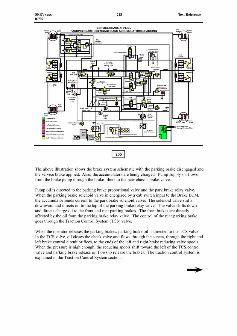
8/9/2019 797F HAA - Meeting Guide.pdf
http://slidepdf.com/reader/full/797f-haa-meeting-guidepdf 276/367
255
The above illustration shows the brake system schematic with the parking brake disengaged andthe service brake applied. Also, the accumulators are being charged. Pump supply oil flowsfrom the brake pump through the brake filters to the new chassis brake valve.
Pump oil is directed to the parking brake proportional valve and the park brake relay valve.When the parking brake solenoid valve in energized by a cab switch input to the Brake ECM,the accumulator sends current to the park brake solenoid valve. The solenoid valve shiftsdownward and directs oil to the top of the parking brake relay valve. The valve shifts downand directs charge oil to the front and rear parking brakes. The front brakes are directlyaffected by the oil from the parking brake relay valve. The control of the rear parking brakegoes through the Traction Control System (TCS) valve.
When the operator releases the parking brakes, parking brake oil is directed to the TCS valve.In the TCS valve, oil closes the check valve and flows through the screen, through the right andleft brake control circuit orifices, to the ends of the left and right brake reducing valve spools.When the pressure is high enough, the reducing spools shift toward the left of the TCS controlvalve and parking brake release oil flows to release the brakes. The traction control system isexplained in the Traction Control System section.
SERVxxxx - 218 - Text Reference07/07
8/9/2019 797F HAA - Meeting Guide.pdf
http://slidepdf.com/reader/full/797f-haa-meeting-guidepdf 277/367
As the operator depresses the service brake valve, the supply oil is directed to both the resolvervalves and the poppet in the resolvers blocks the port from the ARC solenoid valves. Theoil from the service brake valve flows to the pilot end of the relay valves. The oil pressureon the relay valves overrides the spring force and the relay valves shift to the right. Supplyoil is directed to the slack adjusters for the both the front and rear service brakes. Reduced
pressure oil then flows from the service brake relay valve to the two slack adjusters and the two brake control valves. The service brake relay valve provides the flow of oil to move the slackadjuster pistons, and control the brake pressure. The slack adjuster consists of just one pistonand spring to each wheel piston. As the oil pressure is applied to the brake cylinder, the oil
pressure overrides the spring force and the piston engages the service brake pads.
The oil flows from the service brake relay valve to the spring chambers of the slack adjustersand moves the pistons in the slack adjusters outward. The slack adjuster moves a high volumeof oil to move the wheel pistons quickly. At the same time, the oil from the service brake relayvalve flows through the rise rate orifices, to the sequence valves.
The orifices (rise rate) control the rate of flow through the brake control valve to the wheel pistons. At approximately 517 kPa (75 psi), the sequence valves, in the brake control valves,open and allow oil to flow around the slack adjuster to the wheel pistons. This pressuredependent bypass flow path restricts the flow of oil (via the rise rate orifice) that increases
brake pressure. This restriction, in conjunction with the line and brake cylinder volume, actsto dampen sudden pressure increases that occur upstream of the slack adjuster (at the brakes).How hard the brake pedal is depressed, or how far the manual or auto retarder is engaged willdetermine how much pressure is available at the wheel pistons. The maximum pressure at thewheels will be 5930 kPa (860 psi) when the pilot signal to the service brake relay valve is 6615kPa (960 psi).
When the operator releases the service brakes, the oil is drained from the slack adjusters andthe brake control valves through the service brake relay valve. An orifice in the service brakerelay valve drain port controls the rate at which the oil drains (located in a fitting at the chassis
brake valve). The wheel piston return springs push the wheel pistons away from the brakediscs and force the oil from the wheel piston oil chamber. This action causes the slack adjuster
pistons to move toward the center of the slack adjuster and compress the slack adjuster springs.The low reverse restriction to flow fulfills the need to maintain synchronization. This is done
by preventing the slack adjuster piston release movement until after the sequence valve closes,allowing unrestricted flow of oil (via the check valve) that reduces brake pressure.
When the brake pressure drops, the sequence valve closes. The brake piston return springs push the wheel pistons away from the brake discs. The slack adjuster will maintain an oilvolume to the brake piston chamber that positions it for consistent braking as the brake discswear. The residual pressure balances the brake piston return springs after they have extendedand returned the wheel piston. The brake discs separate allowing the cooling oil to flow
between the discs for cooling purposes.
SERVxxxx - 219 - Text Reference07/07
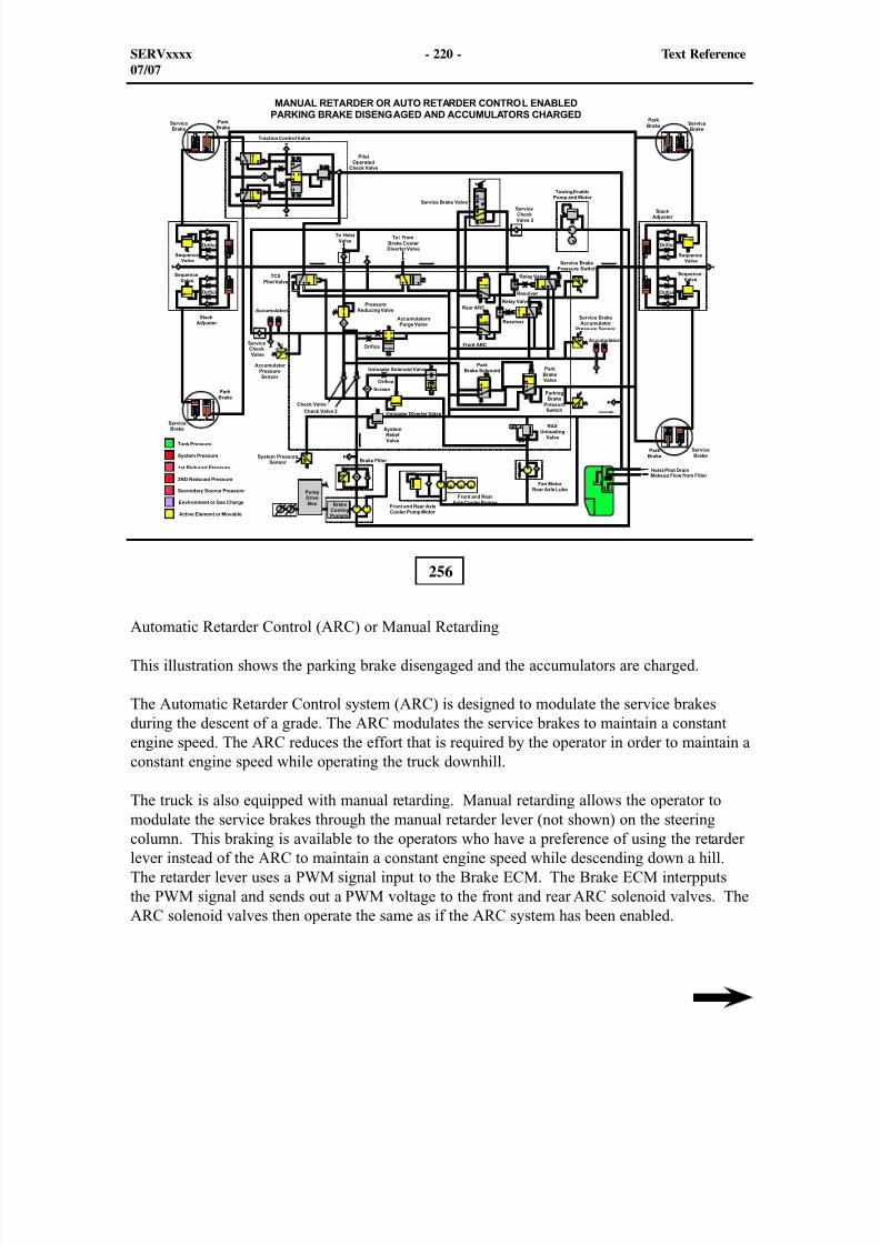
8/9/2019 797F HAA - Meeting Guide.pdf
http://slidepdf.com/reader/full/797f-haa-meeting-guidepdf 278/367
256
Automatic Retarder Control (ARC) or Manual Retarding
This illustration shows the parking brake disengaged and the accumulators are charged.
The Automatic Retarder Control system (ARC) is designed to modulate the service brakesduring the descent of a grade. The ARC modulates the service brakes to maintain a constantengine speed. The ARC reduces the effort that is required by the operator in order to maintain aconstant engine speed while operating the truck downhill.
The truck is also equipped with manual retarding. Manual retarding allows the operator tomodulate the service brakes through the manual retarder lever (not shown) on the steeringcolumn. This braking is available to the operators who have a preference of using the retarderlever instead of the ARC to maintain a constant engine speed while descending down a hill.The retarder lever uses a PWM signal input to the Brake ECM. The Brake ECM interpputsthe PWM signal and sends out a PWM voltage to the front and rear ARC solenoid valves. TheARC solenoid valves then operate the same as if the ARC system has been enabled.
SERVxxxx - 220 - Text Reference07/07
8/9/2019 797F HAA - Meeting Guide.pdf
http://slidepdf.com/reader/full/797f-haa-meeting-guidepdf 279/367
When ARC is enabled and the engine speed/timing sensor senses an increase in desired enginespeed, the Brake ECM sends a proportional current to the front and rear ARC solenoid valves.The solenoid valves shift downward sending a signal through the resolvers which the ballshifts upwards blocking flow to the signal line from the service brake valve. The signal flowsthrough the orifices to the pilot port on the relay valves. The pressure in the line between theslack adjuster and the relay valve will act on the right side of the relay valve and modulate themovement of the relay valve and the service brake actuation. The relay valves direct secondsource oil to the slack adjusters. From there, the slack adjusters act identical to the manualapplication of the service brakes.
The following conditions can cause the ARC function to be engaged: The position of the ARCswitch (not shown) in the cab will be engaged and displayed on the Advisor Module. Refer tothe display time line to observe which ARC feature is enabled. The VIMS with Advisor sectionin this presentation explains the display.
Normal operation occurs when the ARC On/Off switch is in ON position or the manual retarderis activated with the engine RPM above the desired engine speed. The operator should selectthe correct gear for the grade, the load, and the ground conditions. When the transmissionshifts up to the desired gear and the operator has released the throttle, the ARC will control theamount of service brakes keeping the engine speed at the desired engine speed. The desiredengine speed may be programmed by a service person by using Cat ET.
Refer to the Systems Operation manual for the "Machine Speed Limit Function" or "MachineOverload Speed Limit Function" for more information on the speed limits.
Overspeed protection occurs when the ARC detects an engine overspeed situation. The ARCwill engage the brakes regardless of the position of the ARC On/Off switch.
Speed limiting occurs when the Brake ECM receives a machine overspeed from theTransmission ECM. If conditions are correct, the Brake ECM will engage the brakes regardlessof the position of the ARC On/Off switch. The ARC system has several modes of operation.These modes of operation are visible in Cat ET.
Off Mode - This mode indicates that the ARC is not controlling the brakes.
Active Mode - This mode indicates that the ARC is active. However, the engine speed istoo low for the engagement of the brakes.
Retarding Mode - This mode indicates that the ARC is controlling the brakes in order tocontrol the engine speed.
Armed Mode - This mode indicates that the ARC system is inhibited because the throttleis depressed. The ARC will not engage the brakes in this mode.
SERVxxxx - 221 - Text Reference07/07
8/9/2019 797F HAA - Meeting Guide.pdf
http://slidepdf.com/reader/full/797f-haa-meeting-guidepdf 280/367
Fault Mode - This mode indicates that the ARC system may have a diagnostic problem.
Test Mode - This mode is used to test the operation of the ARC while the machine isstationary. This mode may only be entered via Cat ET.
Protect Mode - This mode indicates that there is some exceptional condition that isallowing the engine to overspeed. The ARC system is controlling the brakes in order to controlthe engine overspeed. The protect mode will activate the ARC when the ARC on/off switch isoff and the engine is overspeeding.
If the manual retarder lever and the ARC are ENGAGED at the same time, the control solenoidwill receive a current that corresponds to the system that is requiring the most braking.
Secondary Brake Pedal Is New
The truck is now equipped with a secondary brake pedal (red pedal that is located in the cab)with a position sensor which sends a PM position signal to the Brake ECM. The secondary
brake pedal is used to modulate the disengagement of the parking brakes. Depressing the pedal inputs changes the current output of Brake ECM to the parking brake solenoid. The production 797 truck has a hydraulic valve built into the foot pedal that decreased the pilot oilto the parking brake relay valve which applies the parking brake proportionally to the amountof secondary brake pedal downward movement.
Under normal operation of the parking brake, full current is directed to the parking brakesolenoid (designed to apply the the spring applied brakes if a problem arises with a loss ofcontrol current). Accumulator supplied oil is then directed to the side of the parking brake
piston which disengages the parking brake on all four wheels.
Depressing the secondary pedal sends an input to the Brake ECM. The ECM interpputsthe data. Then, the ECM sends a reduction of current to the parking brake solenoid. The
proportional valve moves in the upward direction and sends a portion of the pilot oil pressuregoing to the parking brake relay to tank. At that time, with a proportional amount of oil to the
parking brake being directed back to the hydraulic tank, with the drop of pressure retracting the parking brake piston, the spring applied parking brake begins to engage the parking brake padsslowing the movement of the truck.
NOTE: If the shift lever is in the park position, the parking brake is commanded tobe engaged and the ECM will not recognize the secondary brake pedal position sensorsignal.
SERVxxxx - 222 - Text Reference07/07
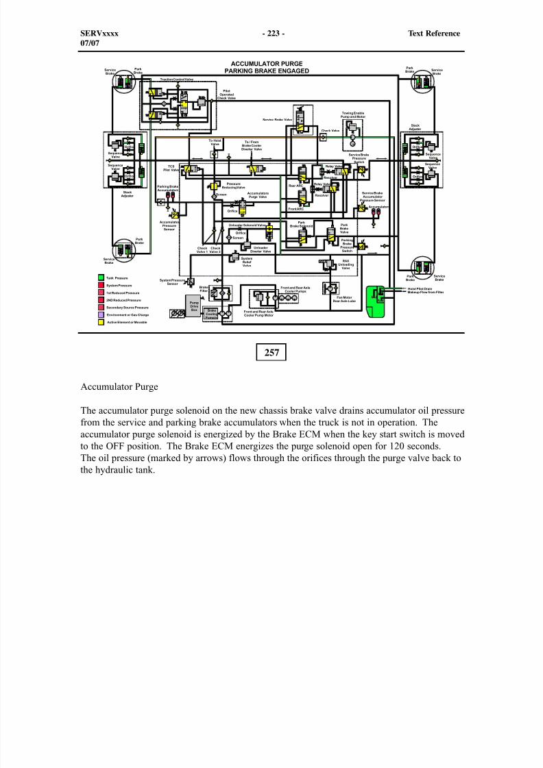
8/9/2019 797F HAA - Meeting Guide.pdf
http://slidepdf.com/reader/full/797f-haa-meeting-guidepdf 281/367
257
Accumulator Purge
The accumulator purge solenoid on the new chassis brake valve drains accumulator oil pressurefrom the service and parking brake accumulators when the truck is not in operation. Theaccumulator purge solenoid is energized by the Brake ECM when the key start switch is movedto the OFF position. The Brake ECM energizes the purge solenoid open for 120 seconds.The oil pressure (marked by arrows) flows through the orifices through the purge valve back tothe hydraulic tank.
SERVxxxx - 223 - Text Reference07/07
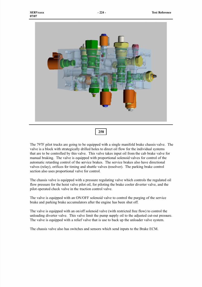
8/9/2019 797F HAA - Meeting Guide.pdf
http://slidepdf.com/reader/full/797f-haa-meeting-guidepdf 282/367
258
The 797F pilot trucks are going to be equipped with a single manifold brake chassis valve. Thevalve is a block with strategically drilled holes to direct oil flow for the individual systemsthat are to be controlled by this valve. This valve takes input oil from the cab brake valve formanual braking. The valve is equipped with proportional solenoid valves for control of theautomatic retarding control of the service brakes. The service brakes also have directionalvalves (relay), orifices for timing and shuttle valves (resolver). The parking brake controlsection also uses proportional valve for control.
The chassis valve is equipped with a pressure regulating valve which controls the regulated oilflow pressure for the hoist valve pilot oil, for piloting the brake cooler diverter valve, and the
pilot operated check valve in the traction control valve.
The valve is equipped with an ON/OFF solenoid valve to control the purging of the service brake and parking brake accumulators after the engine has been shut off.
The valve is equipped with an on/off solenoid valve (with restricted free flow) to control theunloading diverter valve. This valve limit the pump supply oil to the adjusted cut-out pressure.The valve is equipped with a relief valve that is use to back up the unloader valve system.
The chassis valve also has switches and sensors which send inputs to the Brake ECM.
SERVxxxx - 224 - Text Reference07/07
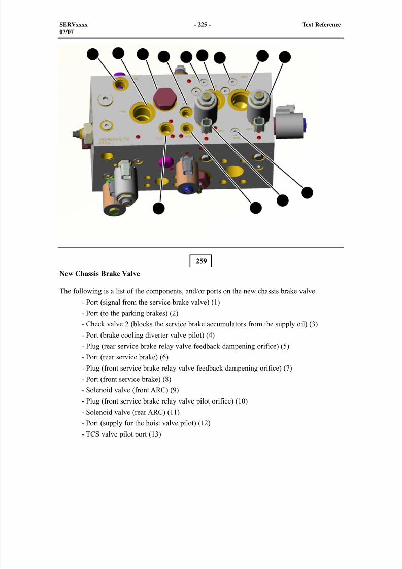
8/9/2019 797F HAA - Meeting Guide.pdf
http://slidepdf.com/reader/full/797f-haa-meeting-guidepdf 283/367
1 2 3 4 5 6 7
259
New Chassis Brake Valve
The following is a list of the components, and/or ports on the new chassis brake valve.
- Port (signal from the service brake valve) (1)
- Port (to the parking brakes) (2)
- Check valve 2 (blocks the service brake accumulators from the supply oil) (3)
- Port (brake cooling diverter valve pilot) (4)
- Plug (rear service brake relay valve feedback dampening orifice) (5)
- Port (rear service brake) (6)
- Plug (front service brake relay valve feedback dampening orifice) (7)
- Port (front service brake) (8)
- Solenoid valve (front ARC) (9)
- Plug (front service brake relay valve pilot orifice) (10)
- Solenoid valve (rear ARC) (11)
- Port (supply for the hoist valve pilot) (12)
- TCS valve pilot port (13)
SERVxxxx - 225 - Text Reference07/07
9
1011
1213
8
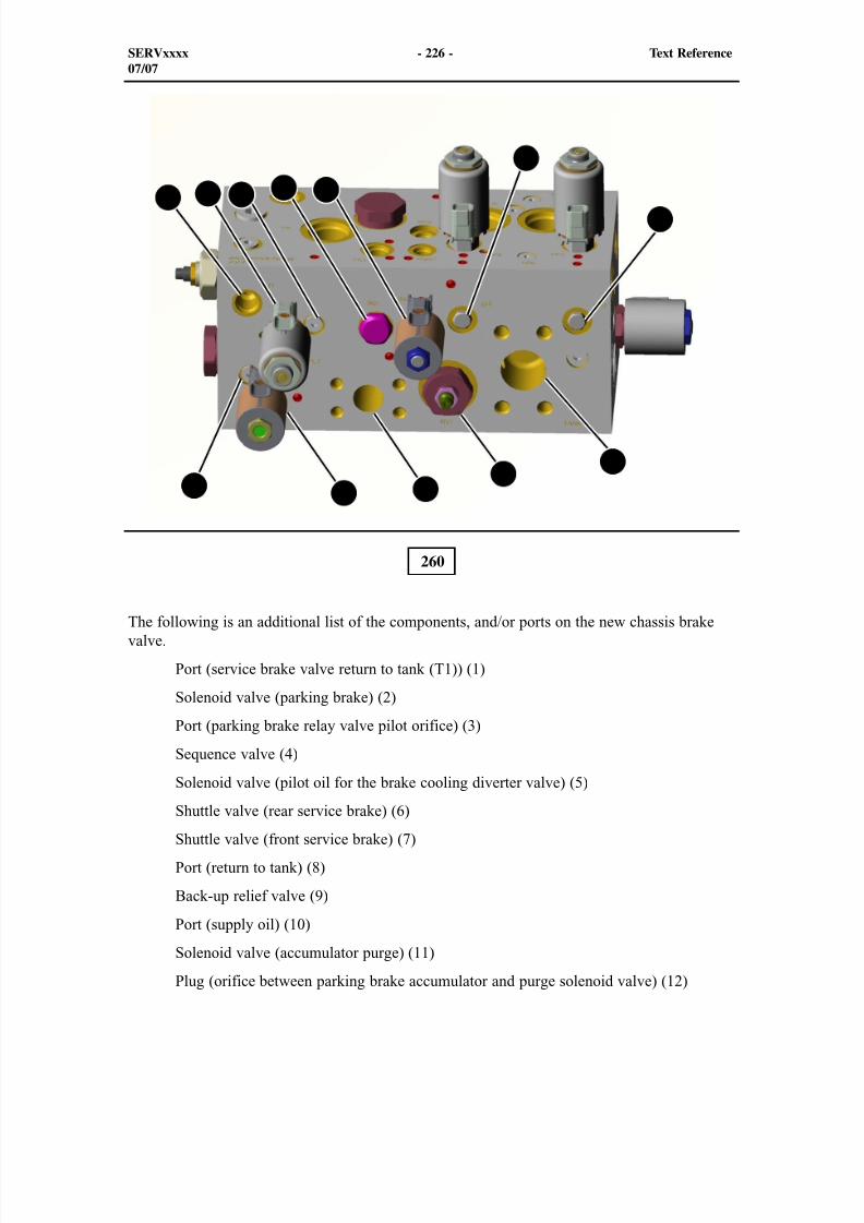
8/9/2019 797F HAA - Meeting Guide.pdf
http://slidepdf.com/reader/full/797f-haa-meeting-guidepdf 284/367
1 2 3 4 5
6
7
260
The following is an additional list of the components, and/or ports on the new chassis brakevalve.
Port (service brake valve return to tank (T1)) (1)
Solenoid valve (parking brake) (2)
Port (parking brake relay valve pilot orifice) (3)
Sequence valve (4)
Solenoid valve (pilot oil for the brake cooling diverter valve) (5)
Shuttle valve (rear service brake) (6)
Shuttle valve (front service brake) (7)
Port (return to tank) (8)
Back-up relief valve (9)
Port (supply oil) (10)
Solenoid valve (accumulator purge) (11)
Plug (orifice between parking brake accumulator and purge solenoid valve) (12)
SERVxxxx - 226 - Text Reference07/07
89
101112
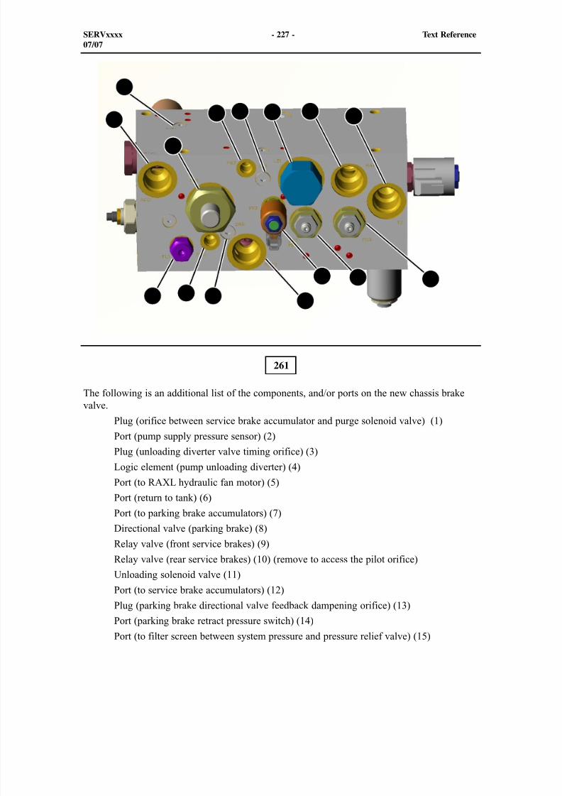
8/9/2019 797F HAA - Meeting Guide.pdf
http://slidepdf.com/reader/full/797f-haa-meeting-guidepdf 285/367
261
The following is an additional list of the components, and/or ports on the new chassis brakevalve.
Plug (orifice between service brake accumulator and purge solenoid valve) (1)
Port (pump supply pressure sensor) (2)
Plug (unloading diverter valve timing orifice) (3)
Logic element (pump unloading diverter) (4)
Port (to RAXL hydraulic fan motor) (5)
Port (return to tank) (6)
Port (to parking brake accumulators) (7)
Directional valve (parking brake) (8)
Relay valve (front service brakes) (9)
Relay valve (rear service brakes) (10) (remove to access the pilot orifice)
Unloading solenoid valve (11)
Port (to service brake accumulators) (12)
Plug (parking brake directional valve feedback dampening orifice) (13)
Port (parking brake retract pressure switch) (14)
Port (to filter screen between system pressure and pressure relief valve) (15)
SERVxxxx - 227 - Text Reference07/07
1
2 3 4 567
8
91011
12131415
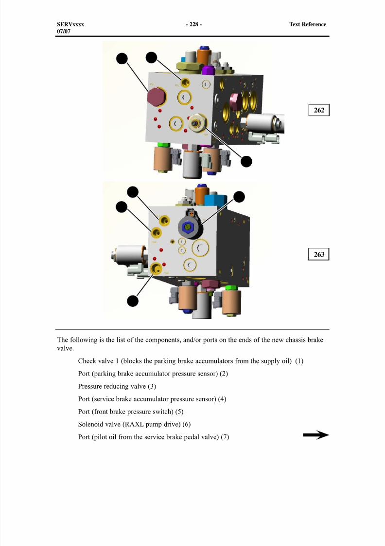
8/9/2019 797F HAA - Meeting Guide.pdf
http://slidepdf.com/reader/full/797f-haa-meeting-guidepdf 286/367
1 2
3
4
5
6
7
The following is the list of the components, and/or ports on the ends of the new chassis brakevalve.
Check valve 1 (blocks the parking brake accumulators from the supply oil) (1)
Port (parking brake accumulator pressure sensor) (2)
Pressure reducing valve (3)
Port (service brake accumulator pressure sensor) (4)
Port (front brake pressure switch) (5)
Solenoid valve (RAXL pump drive) (6)
Port (pilot oil from the service brake pedal valve) (7)
262
263
SERVxxxx - 228 - Text Reference07/07
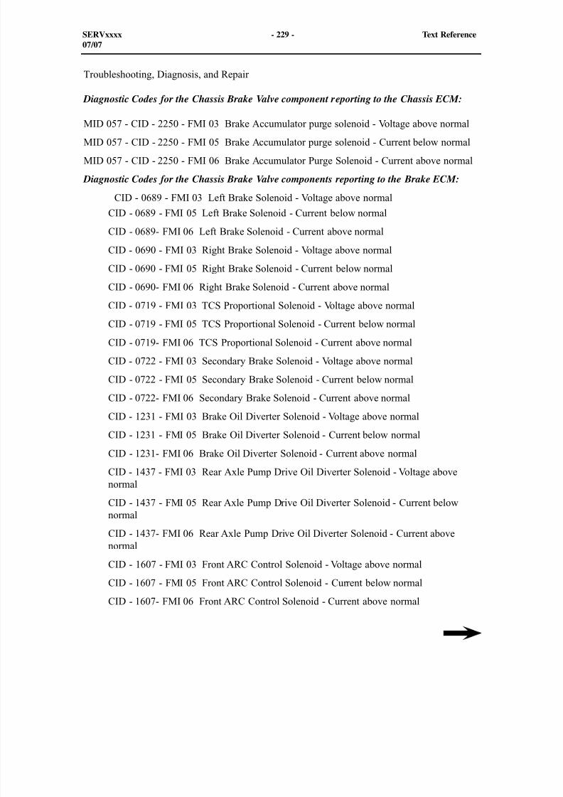
8/9/2019 797F HAA - Meeting Guide.pdf
http://slidepdf.com/reader/full/797f-haa-meeting-guidepdf 287/367
Troubleshooting, Diagnosis, and Repair
Diagnostic Codes for the Chassis Brake Valve component reporting to the Chassis ECM:
MID 057 - CID - 2250 - FMI 03 Brake Accumulator purge solenoid - Voltage above normal
MID 057 - CID - 2250 - FMI 05 Brake Accumulator purge solenoid - Current below normal
MID 057 - CID - 2250 - FMI 06 Brake Accumulator Purge Solenoid - Current above normal
Diagnostic Codes for the Chassis Brake Valve components reporting to the Brake ECM:
CID - 0689 - FMI 03 Left Brake Solenoid - Voltage above normal
CID - 0689 - FMI 05 Left Brake Solenoid - Current below normal
CID - 0689- FMI 06 Left Brake Solenoid - Current above normal
CID - 0690 - FMI 03 Right Brake Solenoid - Voltage above normal
CID - 0690 - FMI 05 Right Brake Solenoid - Current below normal
CID - 0690- FMI 06 Right Brake Solenoid - Current above normal
CID - 0719 - FMI 03 TCS Proportional Solenoid - Voltage above normal
CID - 0719 - FMI 05 TCS Proportional Solenoid - Current below normal
CID - 0719- FMI 06 TCS Proportional Solenoid - Current above normal
CID - 0722 - FMI 03 Secondary Brake Solenoid - Voltage above normal
CID - 0722 - FMI 05 Secondary Brake Solenoid - Current below normal
CID - 0722- FMI 06 Secondary Brake Solenoid - Current above normal
CID - 1231 - FMI 03 Brake Oil Diverter Solenoid - Voltage above normal
CID - 1231 - FMI 05 Brake Oil Diverter Solenoid - Current below normal
CID - 1231- FMI 06 Brake Oil Diverter Solenoid - Current above normal
CID - 1437 - FMI 03 Rear Axle Pump Drive Oil Diverter Solenoid - Voltage abovenormal
CID - 1437 - FMI 05 Rear Axle Pump Drive Oil Diverter Solenoid - Current belownormal
CID - 1437- FMI 06 Rear Axle Pump Drive Oil Diverter Solenoid - Current abovenormal
CID - 1607 - FMI 03 Front ARC Control Solenoid - Voltage above normal
CID - 1607 - FMI 05 Front ARC Control Solenoid - Current below normal
CID - 1607- FMI 06 Front ARC Control Solenoid - Current above normal
SERVxxxx - 229 - Text Reference07/07
8/9/2019 797F HAA - Meeting Guide.pdf
http://slidepdf.com/reader/full/797f-haa-meeting-guidepdf 288/367
CID - 1608 - FMI 03 Rear ARC Control Solenoid - Voltage above normal
CID - 1608 - FMI 05 Rear ARC Control Solenoid - Current below normal
CID - 1608- FMI 06 Rear ARC Control Solenoid - Current above normal
CID - 1961 - FMI 03 Service Brake Accumulator Pressure Sensor - Voltage abovenormal
CID - 1961 - FMI 04 Service Brake Accumulator Pressure Sensor - Voltage belownormal
CID - 1961- FMI 06 Service Brake Accumulator Pressure Sensor - Abnormal frequency, pulse width, or period normal
CID - 1963 - FMI 03 Brake Pump Unloading Solenoid - Voltage above normal
CID - 1963 - FMI 04 Brake Pump Unloading Solenoid - Voltage below normal
CID - 1963- FMI 08 Brake Pump Unloading Solenoid - Abnormal frequency, pulsewidth, or period
CID - 2813 - FMI 03 Secondary Brake Accumulator Pressure Sensor - Voltage abovenormal
CID - 2813 - FMI 05 Secondary Brake Accumulator Pressure Sensor- Current belownormal
CID - 2813- FMI 06 Secondary Brake Accumulator Pressure Sensor - Current abovenormal
NOTE: The Secondary Brake reference in the diagnostic code list will be called theParking Brake through out the rest of the documentation.
SERVxxxx - 230 - Text Reference07/07
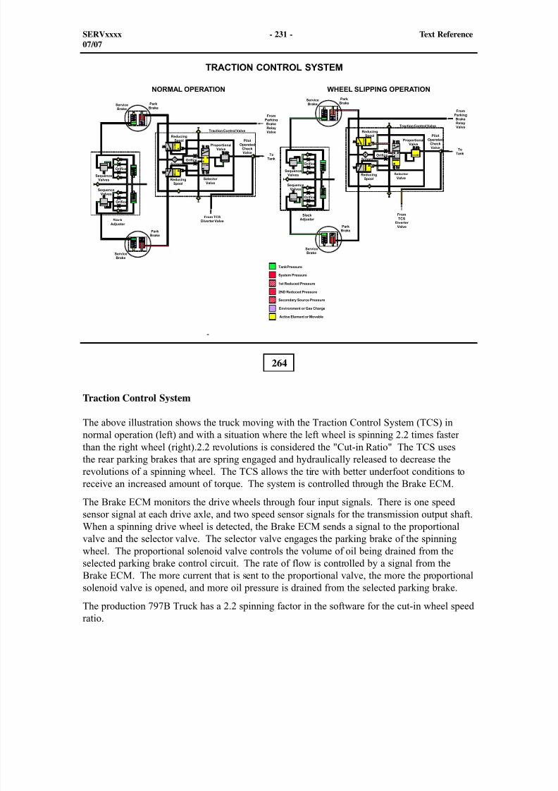
8/9/2019 797F HAA - Meeting Guide.pdf
http://slidepdf.com/reader/full/797f-haa-meeting-guidepdf 289/367
264
Traction Control System
The above illustration shows the truck moving with the Traction Control System (TCS) innormal operation (left) and with a situation where the left wheel is spinning 2.2 times fasterthan the right wheel (right).2.2 revolutions is considered the "Cut-in Ratio" The TCS usesthe rear parking brakes that are spring engaged and hydraulically released to decrease therevolutions of a spinning wheel. The TCS allows the tire with better underfoot conditions toreceive an increased amount of torque. The system is controlled through the Brake ECM.
The Brake ECM monitors the drive wheels through four input signals. There is one speed
sensor signal at each drive axle, and two speed sensor signals for the transmission output shaft.When a spinning drive wheel is detected, the Brake ECM sends a signal to the proportionalvalve and the selector valve. The selector valve engages the parking brake of the spinningwheel. The proportional solenoid valve controls the volume of oil being drained from theselected parking brake control circuit. The rate of flow is controlled by a signal from theBrake ECM. The more current that is sent to the proportional valve, the more the proportionalsolenoid valve is opened, and more oil pressure is drained from the selected parking brake.
The production 797B Truck has a 2.2 spinning factor in the software for the cut-in wheel speedratio.
SERVxxxx - 231 - Text Reference07/07
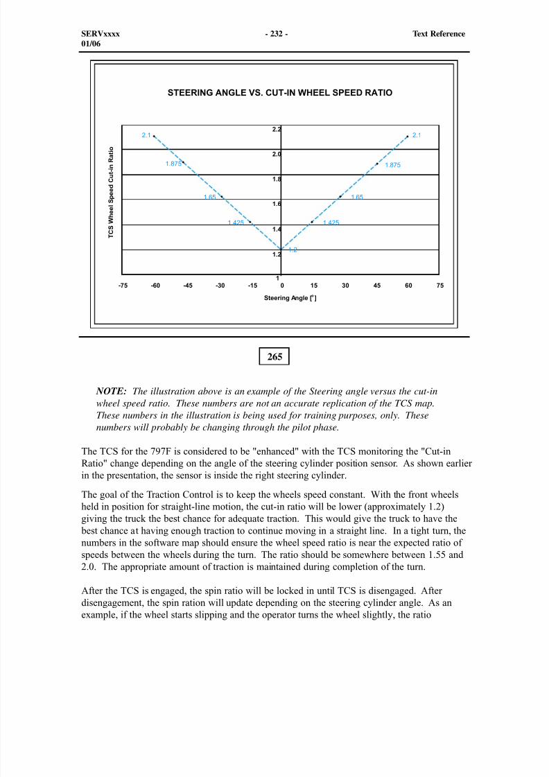
8/9/2019 797F HAA - Meeting Guide.pdf
http://slidepdf.com/reader/full/797f-haa-meeting-guidepdf 290/367
265
NOTE: The illustration above is an example of the Steering angle versus the cut-inwheel speed ratio. These numbers are not an accurate replication of the TCS map.These numbers in the illustration is being used for training purposes, only. Thesenumbers will probably be changing through the pilot phase.
The TCS for the 797F is considered to be "enhanced" with the TCS monitoring the "Cut-inRatio" change depending on the angle of the steering cylinder position sensor. As shown earlierin the presentation, the sensor is inside the right steering cylinder.
The goal of the Traction Control is to keep the wheels speed constant. With the front wheels
held in position for straight-line motion, the cut-in ratio will be lower (approximately 1.2)giving the truck the best chance for adequate traction. This would give the truck to have the best chance at having enough traction to continue moving in a straight line. In a tight turn, thenumbers in the software map should ensure the wheel speed ratio is near the expected ratio ofspeeds between the wheels during the turn. The ratio should be somewhere between 1.55 and2.0. The appropriate amount of traction is maintained during completion of the turn.
After the TCS is engaged, the spin ratio will be locked in until TCS is disengaged. Afterdisengagement, the spin ration will update depending on the steering cylinder angle. As anexample, if the wheel starts slipping and the operator turns the wheel slightly, the ratio
SERVxxxx - 232 - Text Reference01/06
8/9/2019 797F HAA - Meeting Guide.pdf
http://slidepdf.com/reader/full/797f-haa-meeting-guidepdf 291/367
will hold at the lower value no matter what the steering angle is. TCS will have a greaterimpact for regaining traction.
The TCS alert indicator will be illuminated steadily for the duration that the TCS is engaged.
TCS has two test modes: Traction control system dynamic test mode (manual) and(semi-automatic).
Manual Test
The operator initiates the test by holding down the TCS test switch (located in the cab overheadon the left side). This test will reduce the cut-in spin ratio to 1.3 and allow TCS to engageduring slight left or right turns.
Semi-automatic Test
The Traction Control System allows the operator to monitor the TCS Solenoid currents as theyautomatically cycle back and forth.
The operator or technician can initiate this test mode if the truck is in the following state.
Truck is stationary
Service brakes are applied
Parking brake is released
TCS test switch is depressed
The test is initiated through the service tool (ET) and following the on-screen instructions. TheTCS will oscillate the current of each TCS solenoid (right and left) one at a time. First, the leftsolenoid will be engaged, and the current in the TCS Proportional Solenoid will be ramped upto full current, then down to no current. Second, the right solenoid will be engaged and thecurrent in the TCS Proportional Solenoid will be ramped up to full current, then down to nocurrent. The test will continue until stopped by the operator.
Two Diagnostic Codes not covered in the earlier presented in the brake valve diagnostics.
CID - 0607- FMI 02 Left Rear Wheel Speed Sensor - Erratic signal
CID - 0607- FMI 08 Left Rear Wheel Speed Sensor- Abnormal frequency, pulse width,or period
CID - 0608- FMI 02 Right Rear Wheel Speed Sensor - Erratic signal
CID - 0608- FMI 08 Right Rear Wheel Speed Sensor- Abnormal frequency, pulse width,or period
SERVxxxx - 233 - Text Reference01/06
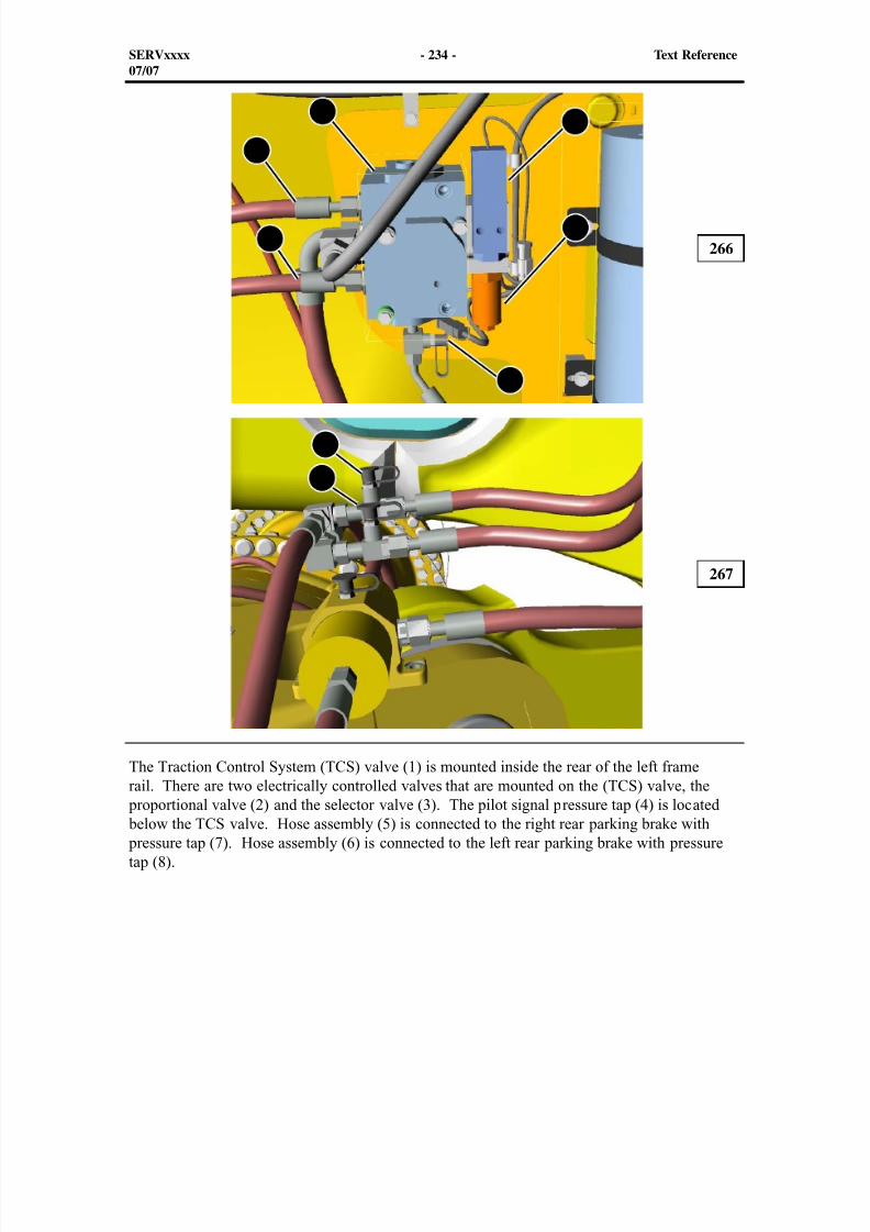
8/9/2019 797F HAA - Meeting Guide.pdf
http://slidepdf.com/reader/full/797f-haa-meeting-guidepdf 292/367
The Traction Control System (TCS) valve (1) is mounted inside the rear of the left framerail. There are two electrically controlled valves that are mounted on the (TCS) valve, the
proportional valve (2) and the selector valve (3). The pilot signal pressure tap (4) is located below the TCS valve. Hose assembly (5) is connected to the right rear parking brake with pressure tap (7). Hose assembly (6) is connected to the left rear parking brake with pressuretap (8).
266
267
SERVxxxx - 234 - Text Reference07/07
12
3
4
6
7
8
5
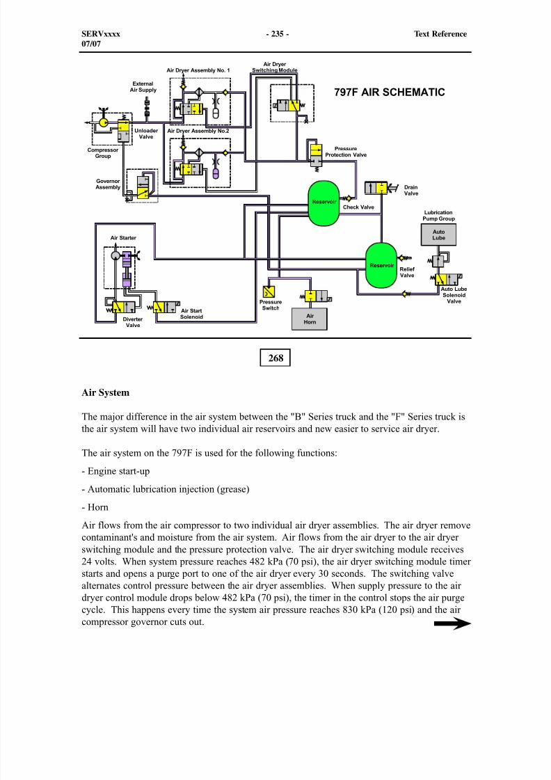
8/9/2019 797F HAA - Meeting Guide.pdf
http://slidepdf.com/reader/full/797f-haa-meeting-guidepdf 293/367
268
Air System
The major difference in the air system between the "B" Series truck and the "F" Series truck isthe air system will have two individual air reservoirs and new easier to service air dryer.
The air system on the 797F is used for the following functions:
- Engine start-up
- Automatic lubrication injection (grease)
- HornAir flows from the air compressor to two individual air dryer assemblies. The air dryer removecontaminant's and moisture from the air system. Air flows from the air dryer to the air dryerswitching module and the pressure protection valve. The air dryer switching module receives24 volts. When system pressure reaches 482 kPa (70 psi), the air dryer switching module timerstarts and opens a purge port to one of the air dryer every 30 seconds. The switching valvealternates control pressure between the air dryer assemblies. When supply pressure to the airdryer control module drops below 482 kPa (70 psi), the timer in the control stops the air purgecycle. This happens every time the system air pressure reaches 830 kPa (120 psi) and the aircompressor governor cuts out.
SERVxxxx - 235 - Text Reference07/07
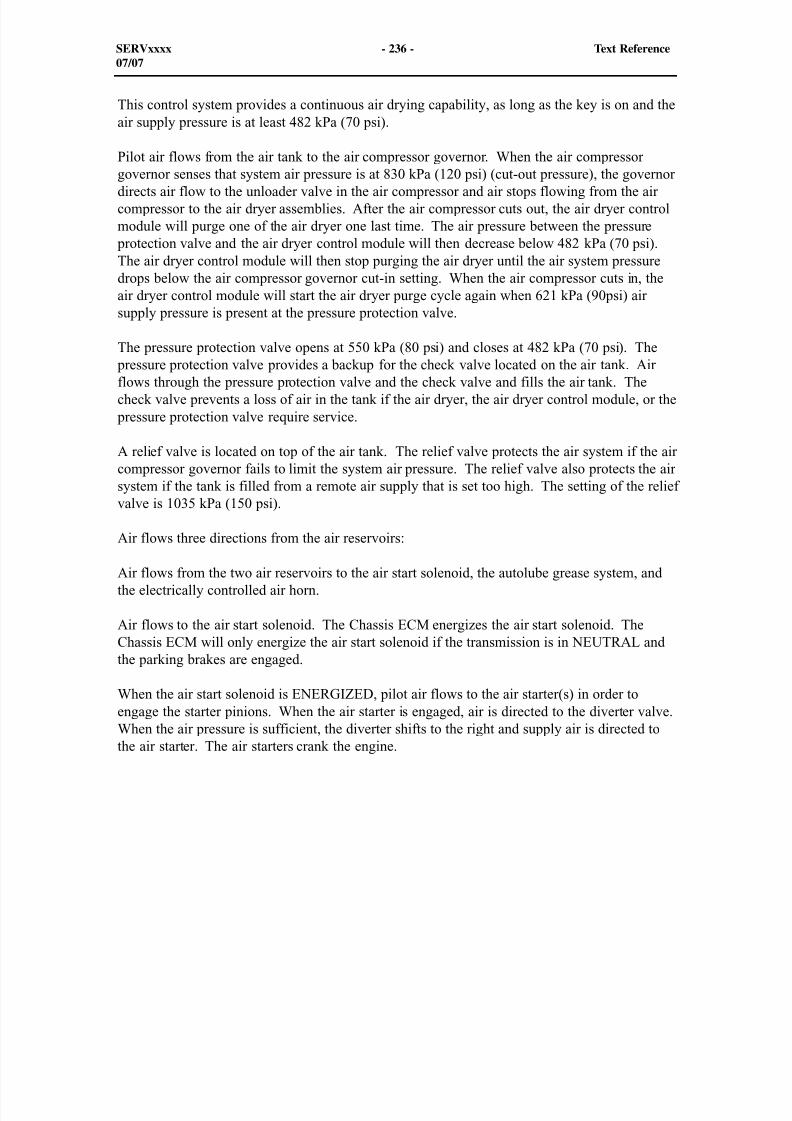
8/9/2019 797F HAA - Meeting Guide.pdf
http://slidepdf.com/reader/full/797f-haa-meeting-guidepdf 294/367
This control system provides a continuous air drying capability, as long as the key is on and theair supply pressure is at least 482 kPa (70 psi).
Pilot air flows from the air tank to the air compressor governor. When the air compressorgovernor senses that system air pressure is at 830 kPa (120 psi) (cut-out pressure), the governordirects air flow to the unloader valve in the air compressor and air stops flowing from the aircompressor to the air dryer assemblies. After the air compressor cuts out, the air dryer controlmodule will purge one of the air dryer one last time. The air pressure between the pressure
protection valve and the air dryer control module will then decrease below 482 kPa (70 psi).The air dryer control module will then stop purging the air dryer until the air system pressuredrops below the air compressor governor cut-in setting. When the air compressor cuts in, theair dryer control module will start the air dryer purge cycle again when 621 kPa (90psi) airsupply pressure is present at the pressure protection valve.
The pressure protection valve opens at 550 kPa (80 psi) and closes at 482 kPa (70 psi). The
pressure protection valve provides a backup for the check valve located on the air tank. Airflows through the pressure protection valve and the check valve and fills the air tank. Thecheck valve prevents a loss of air in the tank if the air dryer, the air dryer control module, or the
pressure protection valve require service.
A relief valve is located on top of the air tank. The relief valve protects the air system if the aircompressor governor fails to limit the system air pressure. The relief valve also protects the airsystem if the tank is filled from a remote air supply that is set too high. The setting of the reliefvalve is 1035 kPa (150 psi).
Air flows three directions from the air reservoirs:
Air flows from the two air reservoirs to the air start solenoid, the autolube grease system, andthe electrically controlled air horn.
Air flows to the air start solenoid. The Chassis ECM energizes the air start solenoid. TheChassis ECM will only energize the air start solenoid if the transmission is in NEUTRAL andthe parking brakes are engaged.
When the air start solenoid is ENERGIZED, pilot air flows to the air starter(s) in order toengage the starter pinions. When the air starter is engaged, air is directed to the diverter valve.
When the air pressure is sufficient, the diverter shifts to the right and supply air is directed tothe air starter. The air starters crank the engine.
SERVxxxx - 236 - Text Reference07/07
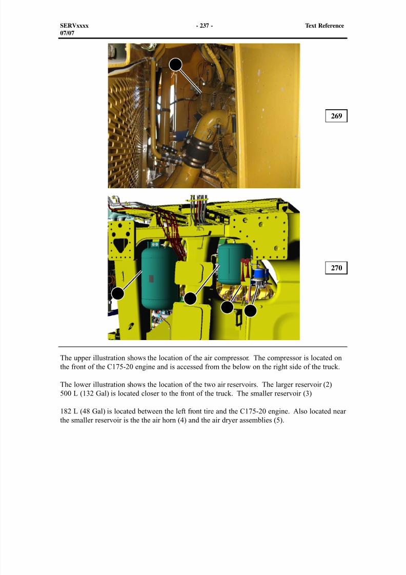
8/9/2019 797F HAA - Meeting Guide.pdf
http://slidepdf.com/reader/full/797f-haa-meeting-guidepdf 295/367
The upper illustration shows the location of the air compressor. The compressor is located onthe front of the C175-20 engine and is accessed from the below on the right side of the truck.
The lower illustration shows the location of the two air reservoirs. The larger reservoir (2)500 L (132 Gal) is located closer to the front of the truck. The smaller reservoir (3)
182 L (48 Gal) is located between the left front tire and the C175-20 engine. Also located nearthe smaller reservoir is the the air horn (4) and the air dryer assemblies (5).
269
270
SERVxxxx - 237 - Text Reference07/07
1
23
4 5
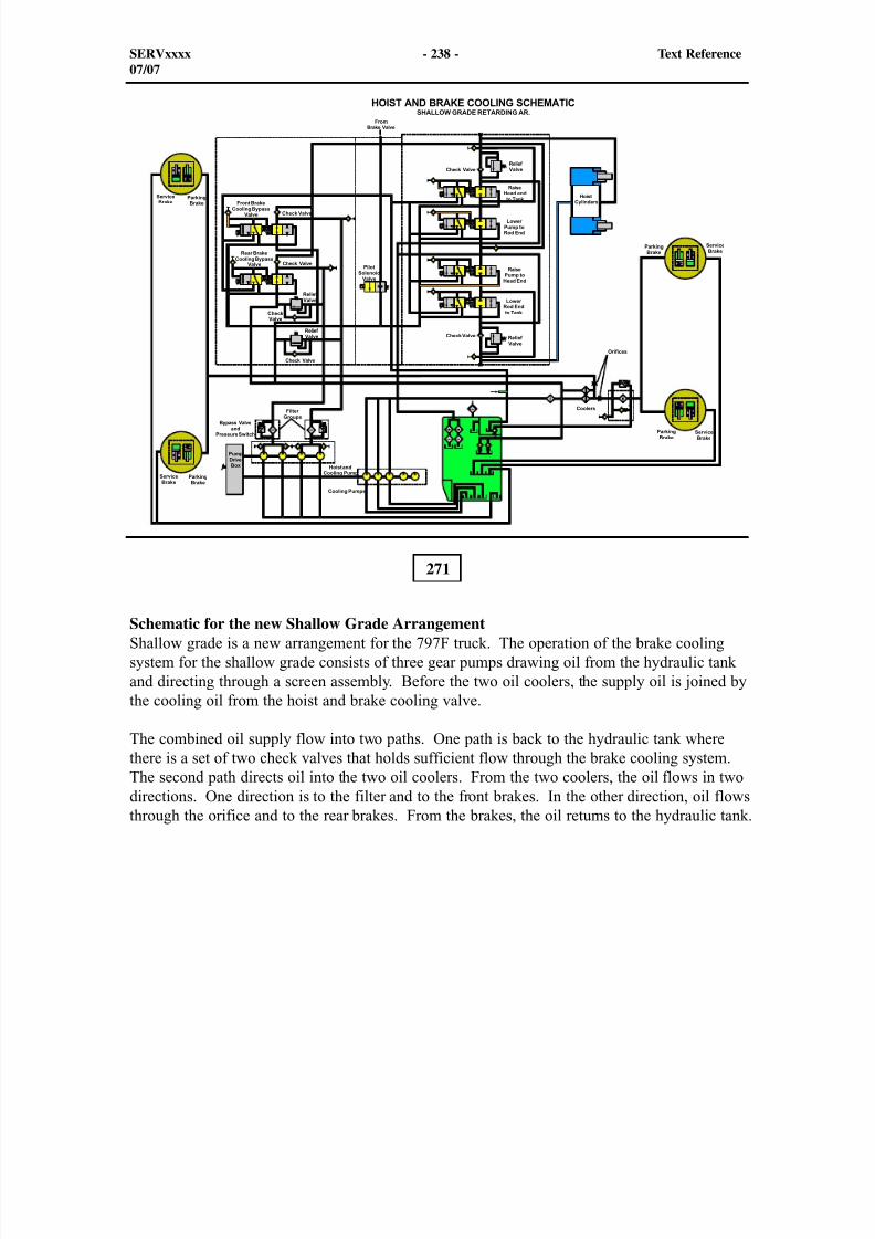
8/9/2019 797F HAA - Meeting Guide.pdf
http://slidepdf.com/reader/full/797f-haa-meeting-guidepdf 296/367
271
Schematic for the new Shallow Grade ArrangementShallow grade is a new arrangement for the 797F truck. The operation of the brake coolingsystem for the shallow grade consists of three gear pumps drawing oil from the hydraulic tankand directing through a screen assembly. Before the two oil coolers, the supply oil is joined bythe cooling oil from the hoist and brake cooling valve.
The combined oil supply flow into two paths. One path is back to the hydraulic tank wherethere is a set of two check valves that holds sufficient flow through the brake cooling system.The second path directs oil into the two oil coolers. From the two coolers, the oil flows in twodirections. One direction is to the filter and to the front brakes. In the other direction, oil flowsthrough the orifice and to the rear brakes. From the brakes, the oil returns to the hydraulic tank.
SERVxxxx - 238 - Text Reference07/07
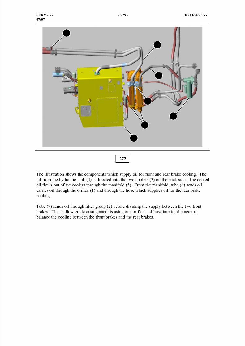
8/9/2019 797F HAA - Meeting Guide.pdf
http://slidepdf.com/reader/full/797f-haa-meeting-guidepdf 297/367
272
The illustration shows the components which supply oil for front and rear brake cooling. Theoil from the hydraulic tank (4) is directed into the two coolers (3) on the back side. The cooledoil flows out of the coolers through the manifold (5). From the manifold, tube (6) sends oilcarries oil through the orifice (1) and through the hose which supplies oil for the rear brakecooling.
Tube (7) sends oil through filter group (2) before dividing the supply between the two front brakes. The shallow grade arrangement is using one orifice and hose interior diameter to balance the cooling between the front brakes and the rear brakes.
SERVxxxx - 239 - Text Reference07/07
1
2
3
4
5
6
7
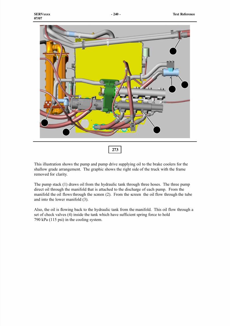
8/9/2019 797F HAA - Meeting Guide.pdf
http://slidepdf.com/reader/full/797f-haa-meeting-guidepdf 298/367
1
2
3
4
5
6
273
This illustration shows the pump and pump drive supplying oil to the brake coolers for theshallow grade arrangement. The graphic shows the right side of the truck with the frameremoved for clarity.
The pump stack (1) draws oil from the hydraulic tank through three hoses. The three pumpdirect oil through the manifold that is attached to the discharge of each pump. From themanifold the oil flows through the screen (2). From the screen the oil flow through the tubeand into the lower manifold (3).
Also, the oil is flowing back to the hydraulic tank from the manifold. This oil flow through aset of check valves (4) inside the tank which have sufficient spring force to hold790 kPa (115 psi) in the cooling system.
SERVxxxx - 240 - Text Reference07/07
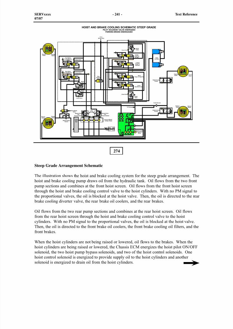
8/9/2019 797F HAA - Meeting Guide.pdf
http://slidepdf.com/reader/full/797f-haa-meeting-guidepdf 299/367
274
Steep Grade Arrangement Schematic
The illustration shows the hoist and brake cooling system for the steep grade arrangement. Thehoist and brake cooling pump draws oil from the hydraulic tank. Oil flows from the two front
pump sections and combines at the front hoist screen. Oil flows from the front hoist screenthrough the hoist and brake cooling control valve to the hoist cylinders. With no PM signal tothe proportional valves, the oil is blocked at the hoist valve. Then, the oil is directed to the rear
brake cooling diverter valve, the rear brake oil coolers, and the rear brakes.
Oil flows from the two rear pump sections and combines at the rear hoist screen. Oil flowsfrom the rear hoist screen through the hoist and brake cooling control valve to the hoistcylinders. With no PM signal to the proportional valves, the oil is blocked at the hoist valve.Then, the oil is directed to the front brake oil coolers, the front brake cooling oil filters, and thefront brakes.
When the hoist cylinders are not being raised or lowered, oil flows to the brakes. When thehoist cylinders are being raised or lowered, the Chassis ECM energizes the hoist pilot ON/OFFsolenoid, the two hoist pump bypass solenoids, and two of the hoist control solenoids. Onehoist control solenoid is energized to provide supply oil to the hoist cylinders and anothersolenoid is energized to drain oil from the hoist cylinders.
SERVxxxx - 241 - Text Reference07/07
8/9/2019 797F HAA - Meeting Guide.pdf
http://slidepdf.com/reader/full/797f-haa-meeting-guidepdf 300/367
Rear brake cooling oil flows through the diverter valve. The diverter valve is located behind onthe right side of the truck next to the brake system filter. When brake oil temperature is greaterthan 107°C (225°F), the Brake ECM sends +24 Volts to energize the brake cooling oil divertervalve solenoid. When the solenoid is energized, signal oil flows from the chassis brake valveto the diverter valve. When signal oil is present, oil flows through the diverter valve and therear brake oil coolers, to the rear brakes. When the solenoid is de-energized, the hoist pump oil
bypasses the rear brake oil coolers and flows directly to the rear brakes.
Hoist pilot oil pressure is controlled at the chassis brake valve by a pressure reducing valve.Hoist pilot oil flows to the hoist valve manifold. The pilot oil enable solenoid controls the flowof pilot oil to the top and bottom of all of the directional spools in the hoist valve.
A brake cooling drive pump is located at the bottom rear of the pump drive. Oil flows fromthe brake cooling drive pump to the brake cooling drive motor and drives three brake cooling
pumps located in the hydraulic tank. Oil flows from the rear brake cooling pump and joins
with the hoist oil to cool the front brakes. Oil flows from the two front pumps and joins withthe hoist oil to cool the rear brakes.
The Brake ECM controls a solenoid on the brake cooling drive pump. When brake oiltemperature is less than 102°C (215°F), the solenoid for the brake cooling drive pump is de-energized. The piston pump goes to low pressure standby. Only oil necessary for responseand lubrication is developed by the brake cooling pump. When brake oil temperature is greaterthan 102°C (215°F) but less than 107°C (225°F), the Brake ECM sends a PM signal to the
brake cooling drive pump to modulate the brake cooling flow from the pumps. When brake oiltemperature is greater than 107°C (225°F), the Brake/Cooling ECM sends a signal to the brakecooling drive pump to provide maximum brake cooling flow from the pumps.
The rotation of the hydraulic pumps that are driven by the pump drive have changed fromcounterclockwise direction to clockwise direction. The pump drive rotation has changed due tothe engine power out drive shaft rotation on the C175 engine is now reversed compared to the"B" series.
SERVxxxx - 242 - Text Reference07/07
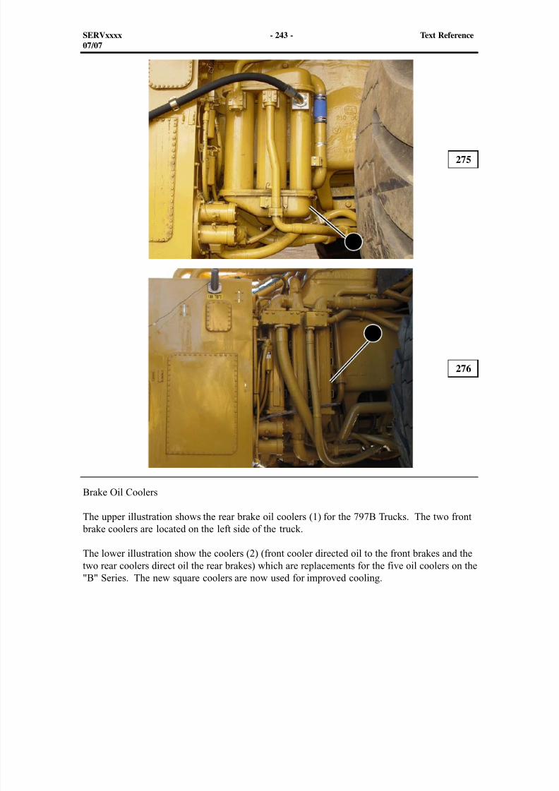
8/9/2019 797F HAA - Meeting Guide.pdf
http://slidepdf.com/reader/full/797f-haa-meeting-guidepdf 301/367
1
2
Brake Oil Coolers
The upper illustration shows the rear brake oil coolers (1) for the 797B Trucks. The two front brake coolers are located on the left side of the truck.
The lower illustration show the coolers (2) (front cooler directed oil to the front brakes and thetwo rear coolers direct oil the rear brakes) which are replacements for the five oil coolers on the"B" Series. The new square coolers are now used for improved cooling.
275
276
SERVxxxx - 243 - Text Reference07/07
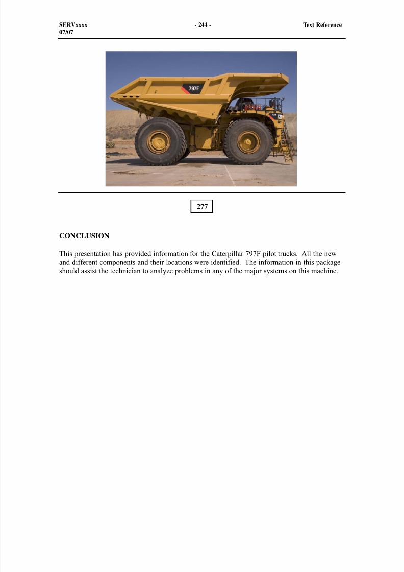
8/9/2019 797F HAA - Meeting Guide.pdf
http://slidepdf.com/reader/full/797f-haa-meeting-guidepdf 302/367
CONCLUSION
This presentation has provided information for the Caterpillar 797F pilot trucks. All the newand different components and their locations were identified. The information in this packageshould assist the technician to analyze problems in any of the major systems on this machine.
277
SERVxxxx - 244 - Text Reference07/07
8/9/2019 797F HAA - Meeting Guide.pdf
http://slidepdf.com/reader/full/797f-haa-meeting-guidepdf 303/367
LAB OBJECTIVESThis laboratory exercises measures your ability to identify, point out, and describe the systemson the 797F Pilot trucks.
In the labs, follow the directions in the worksheets to complete the labs. During the class presentation, take notes as the function, operation and location of different component discussedin the presentation about the new 797F Pilot Truck.
INDIVIDUAL LAB OBJECTIVES
1. Given a 797F Series Pilot Truck, locate and identify the C175-20components during the lab exercise.
2. Given a 797F Series Pilot Truck, locate and identify the Cabcomponents during the lab exercise.
3. Given a 797F Series Pilot Truck, match the operation at theleft with the callouts (graphic) for the new externally mountedtransmission pressure tap block.
4. Given a 797F Series Pilot Truck, with the provided writinginstrument, write a brief explanation about what is shown in the
brake graphic
5. Given a 797F Series Pilot Truck, with the provided writinginstrument, write a brief explanation about what is shown in thesecond brake graphic
6. Given a 797F Series Pilot Truck, with the provided writing
instrument, match the component numbers in the graphic withthe components listed to the right.
7. Given a 797F Series Pilot Truck, with the provided writinginstrument, write a brief explanation about what is shown in theschematic for the shallow grade (graphic)
LAB A:
LAB B:
LAB C:
LAB D:
LAB E:
LAB F:
LAB G:
SERVxxxx - 245 - LAB Questions07/07
8/9/2019 797F HAA - Meeting Guide.pdf
http://slidepdf.com/reader/full/797f-haa-meeting-guidepdf 304/367
SERVxxxx - 246 - LAB Questions07/07
Lab A: Caterpillar C175-20 Engine Component Identification Worksheet
Use this worksheet during the presentation to fill in the blank spaces indicating the locationand function of each component. If the instructor decides to use tags in the lab
exercise, match the tag attached to the component with the correct name.
797F Truck Engine Component Locations And Functions
___ Engine ECM Location:Function:
___ Engine oil low level switch Location:Function:
___ High pressure fuel rail pressure sensor Location:Function:
___ Engine oil cooler cores Location:Function:
___ Crankshaft speed/timing sensor Location:Function:
___ Engine oil sight glass Location:Function:
___ Coolant pump
Location:Function: .
___ Block coolant outlet temperature sensor Location:Function:
8/9/2019 797F HAA - Meeting Guide.pdf
http://slidepdf.com/reader/full/797f-haa-meeting-guidepdf 305/367
SERVxxxx - 247 - LAB Questions07/07
Lab A: Caterpillar C175-20 Engine Component Identification Worksheet (continued)
___ Intake manifold temperature sensor Location:Function:
___ Block oil pressure and temperature sensors Location:Function:
___ Fuel transfer pump and pressure sensor Location:
Function:
___ Camshaft speed/timing sensors Location:Function:
___ High pressure fuel pump and monoblock block Location:Function:
___ Secondary fuel filters and pressure sensors Location:Function:
___ Air conditioning compressor Location:Function:
___ Crankcase pressure sensors Location:Function:
___ Block coolant outlet pressure sensor Location:Function:
___ Atmospheric pressure sensor Location:Function:
8/9/2019 797F HAA - Meeting Guide.pdf
http://slidepdf.com/reader/full/797f-haa-meeting-guidepdf 306/367
SERVxxxx - 248 - LAB Questions07/07
Lab B: 797F Cab Component Identification Worksheet
Use this worksheet during the presentation to fill in the blank spaces indicating the locationand function of each component. If the instructor decides to use tags in the lab
exercise, match the tag attached to the component with the correct name.797F Truck Engine Component Locations And Functions
___ Transmission ECM Location:Function:
___ VIMS Main module Location:Function:
___ Service connector Location:Function:
___ Fuel accelerator pedal Location:Function:
___ 24 to 12 volt converter Location:
Function:
___ Secondary brake pedal sensor Location:Function:
___ Chassis ECM Location:Function: .
___ Service brake pedal Location:Function:
___ Left side light and switch Location:Function:
8/9/2019 797F HAA - Meeting Guide.pdf
http://slidepdf.com/reader/full/797f-haa-meeting-guidepdf 307/367
SERVxxxx - 249 - LAB Questions07/07
Lab B: Implement Hydraulic System Component Identification Worksheet(continued)
___ Traction control test switch
Location:Function:
___ Secondary steering test switch Location:Function:
___ Shift down button switch Location:Function:
___ Throttle lock switch Location:Function:
___ Brake retract switch Location:Function:
___ HVAC condenser relay Location:Function:
___ VIMS analysis module Location:Function:
___ Auto retarding switch Location:Function:
___ Left hand window rocker switch
Location:Function:
___ Transmission shift lever Location:Function:
___ Brake ECM Location:Function:
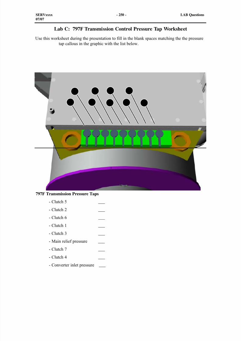
8/9/2019 797F HAA - Meeting Guide.pdf
http://slidepdf.com/reader/full/797f-haa-meeting-guidepdf 308/367
797F Transmission Pressure Taps
- Clutch 5 ___
- Clutch 2 ___
- Clutch 6 ___
- Clutch 1 ___
- Clutch 3 ___
- Main relief pressure ___
- Clutch 7 ___
- Clutch 4 ___
- Converter inlet pressure ___
SERVxxxx - 250 - LAB Questions07/07
1
2
3
4
5
6
7
8
9
Lab C: 797F Transmission Control Pressure Tap Worksheet
Use this worksheet during the presentation to fill in the blank spaces matching the the pressuretap callous in the graphic with the list below.
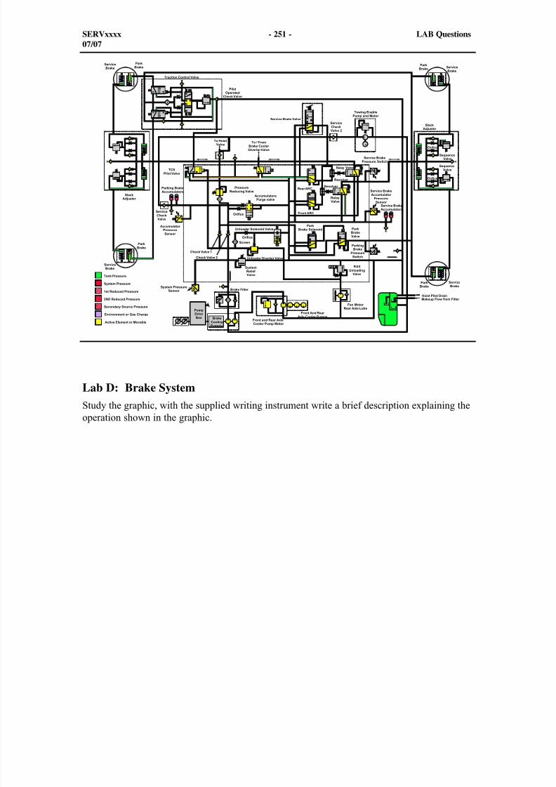
8/9/2019 797F HAA - Meeting Guide.pdf
http://slidepdf.com/reader/full/797f-haa-meeting-guidepdf 309/367
Lab D: Brake SystemStudy the graphic, with the supplied writing instrument write a brief description explaining theoperation shown in the graphic.
SERVxxxx - 251 - LAB Questions07/07

8/9/2019 797F HAA - Meeting Guide.pdf
http://slidepdf.com/reader/full/797f-haa-meeting-guidepdf 310/367
SERVxxxx - 252 - Text Reference07/07
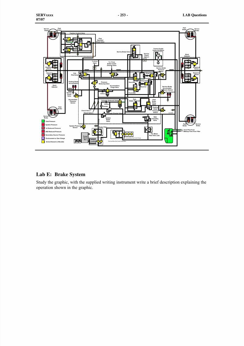
8/9/2019 797F HAA - Meeting Guide.pdf
http://slidepdf.com/reader/full/797f-haa-meeting-guidepdf 311/367
Lab E: Brake SystemStudy the graphic, with the supplied writing instrument write a brief description explaining theoperation shown in the graphic.
SERVxxxx - 253 - LAB Questions07/07

8/9/2019 797F HAA - Meeting Guide.pdf
http://slidepdf.com/reader/full/797f-haa-meeting-guidepdf 312/367
SERVxxxx - 254 - Text Reference07/07
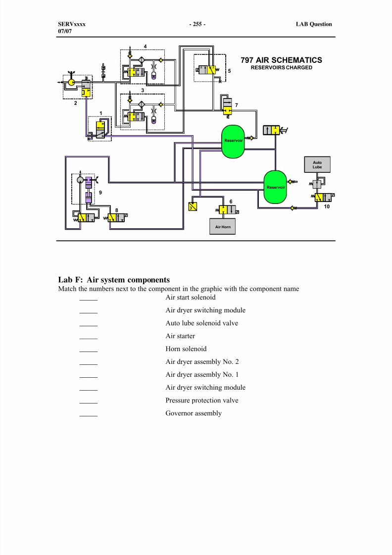
8/9/2019 797F HAA - Meeting Guide.pdf
http://slidepdf.com/reader/full/797f-haa-meeting-guidepdf 313/367
Lab F: Air system componentsMatch the numbers next to the component in the graphic with the component name _____ Air start solenoid
_____ Air dryer switching module
_____ Auto lube solenoid valve
_____ Air starter
_____ Horn solenoid
_____ Air dryer assembly No. 2 _____ Air dryer assembly No. 1
_____ Air dryer switching module
_____ Pressure protection valve
_____ Governor assembly
SERVxxxx - 255 - LAB Question07/07
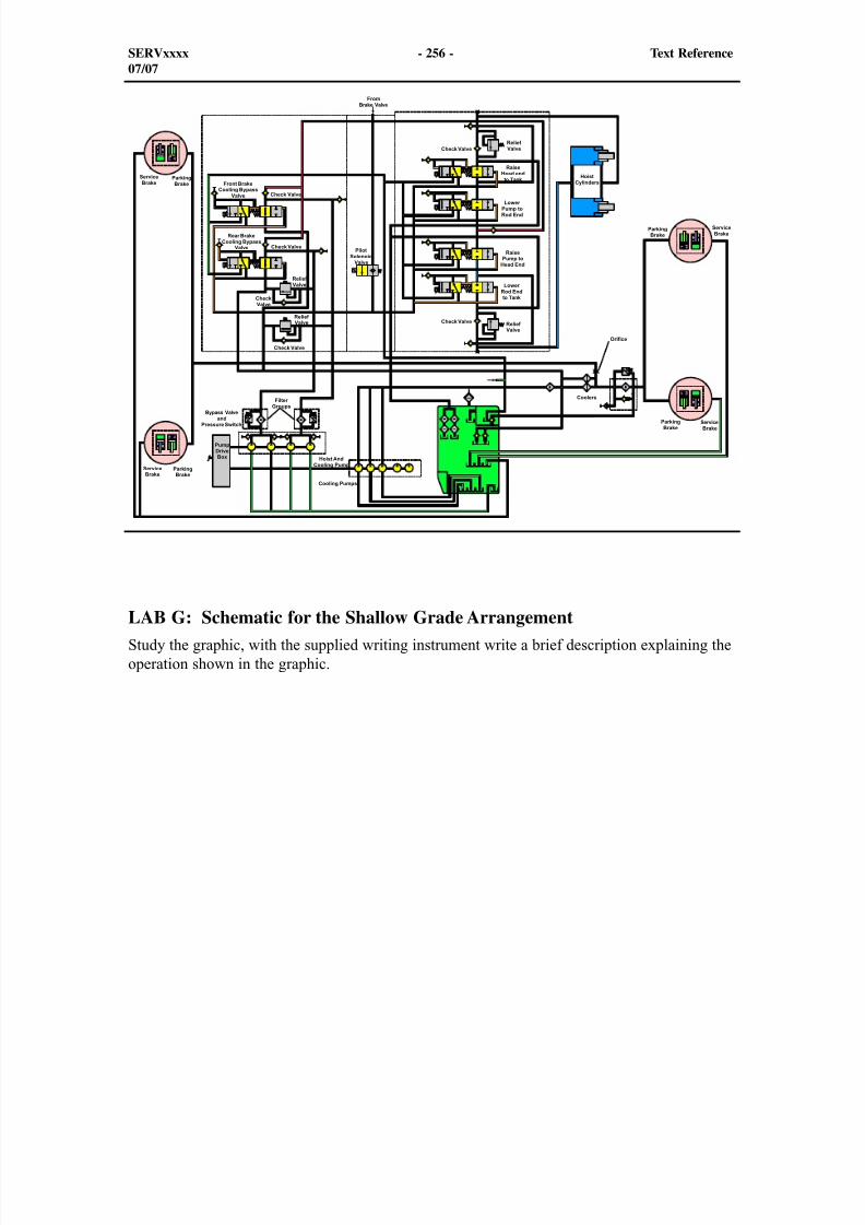
8/9/2019 797F HAA - Meeting Guide.pdf
http://slidepdf.com/reader/full/797f-haa-meeting-guidepdf 314/367
LAB G: Schematic for the Shallow Grade ArrangementStudy the graphic, with the supplied writing instrument write a brief description explaining theoperation shown in the graphic.
SERVxxxx - 256 - Text Reference07/07
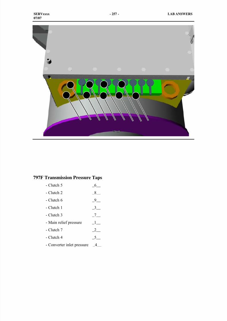
8/9/2019 797F HAA - Meeting Guide.pdf
http://slidepdf.com/reader/full/797f-haa-meeting-guidepdf 315/367
797F Transmission Pressure Taps
- Clutch 5 _6__
- Clutch 2 _8__
- Clutch 6 _9__
- Clutch 1 _3__
- Clutch 3 _7__
- Main relief pressure _1__
- Clutch 7 _2__
- Clutch 4 _5__
- Converter inlet pressure _4__
SERVxxxx - 257 - LAB ANSWERS07/07
1
2
3
4
5
6
7
8
9
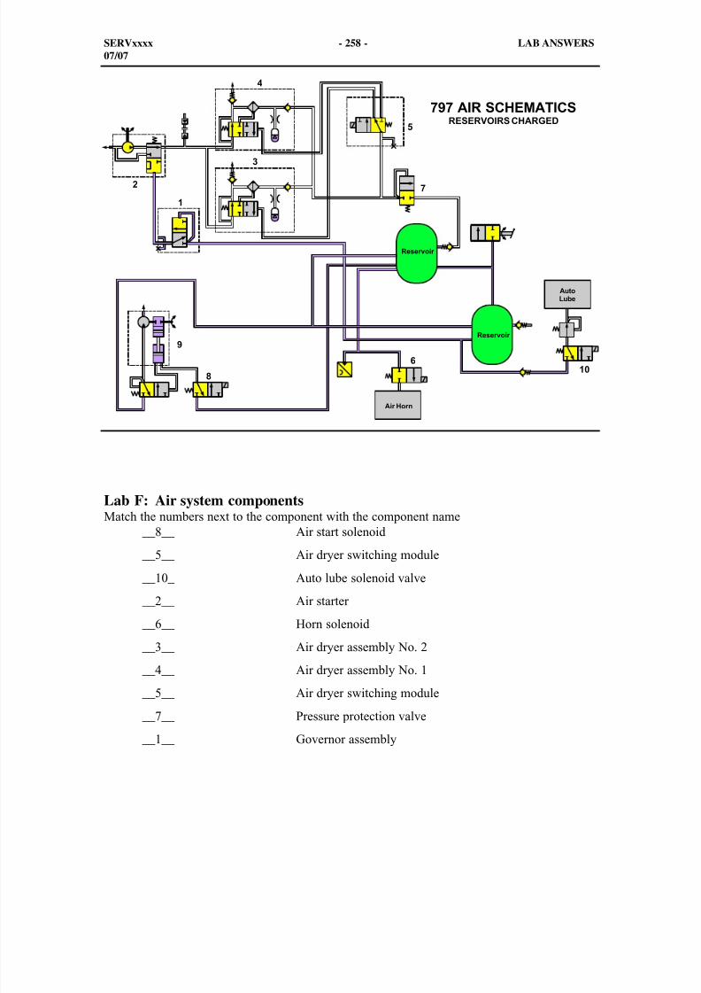
8/9/2019 797F HAA - Meeting Guide.pdf
http://slidepdf.com/reader/full/797f-haa-meeting-guidepdf 316/367
Lab F: Air system componentsMatch the numbers next to the component with the component name __8__ Air start solenoid
__5__ Air dryer switching module
__10_ Auto lube solenoid valve
__2__ Air starter
__6__ Horn solenoid
__3__ Air dryer assembly No. 2 __4__ Air dryer assembly No. 1
__5__ Air dryer switching module
__7__ Pressure protection valve
__1__ Governor assembly
SERVxxxx - 258 - LAB ANSWERS07/07

8/9/2019 797F HAA - Meeting Guide.pdf
http://slidepdf.com/reader/full/797f-haa-meeting-guidepdf 317/367
GLOBAL SERVICE LEARNING
TECHNICAL PRESENTATION
VIMS3GFOR THE 797F PILOT
LARGE OFF-HIGHWAY TRUCK
SERVxxxx April 2008
8/9/2019 797F HAA - Meeting Guide.pdf
http://slidepdf.com/reader/full/797f-haa-meeting-guidepdf 318/367
Internet Protocols In The Main Module
Connecting Cat ET to the truck for resetting the Internet Protocols (IP address). Beforeattempting to connect with the VIMS Main module, ensure that the computer being used isequipped with Caterpillar ET Version 2007C or later. Connect the new 305-5528 - Cable to theVIMS port in the cab and the serial plug of the cable to the serial port on the backside of theoff-board computer. Do not connect the Ethernet section of the cable at this time
To communicate between the off-board computer and the VIMS modules, there are somedirections that need to be followed.
Double click on the Cat ET icon on the off-board computer and follow the directions on thescreen. When the connections are correct, the screen will show a vertical list of the truckECMs.
The first step is to change the internet protocols in the VIMS Main Module. Follow thedirections to complete the setup.
1
SERVxxxx - 2 - Text Reference03/08
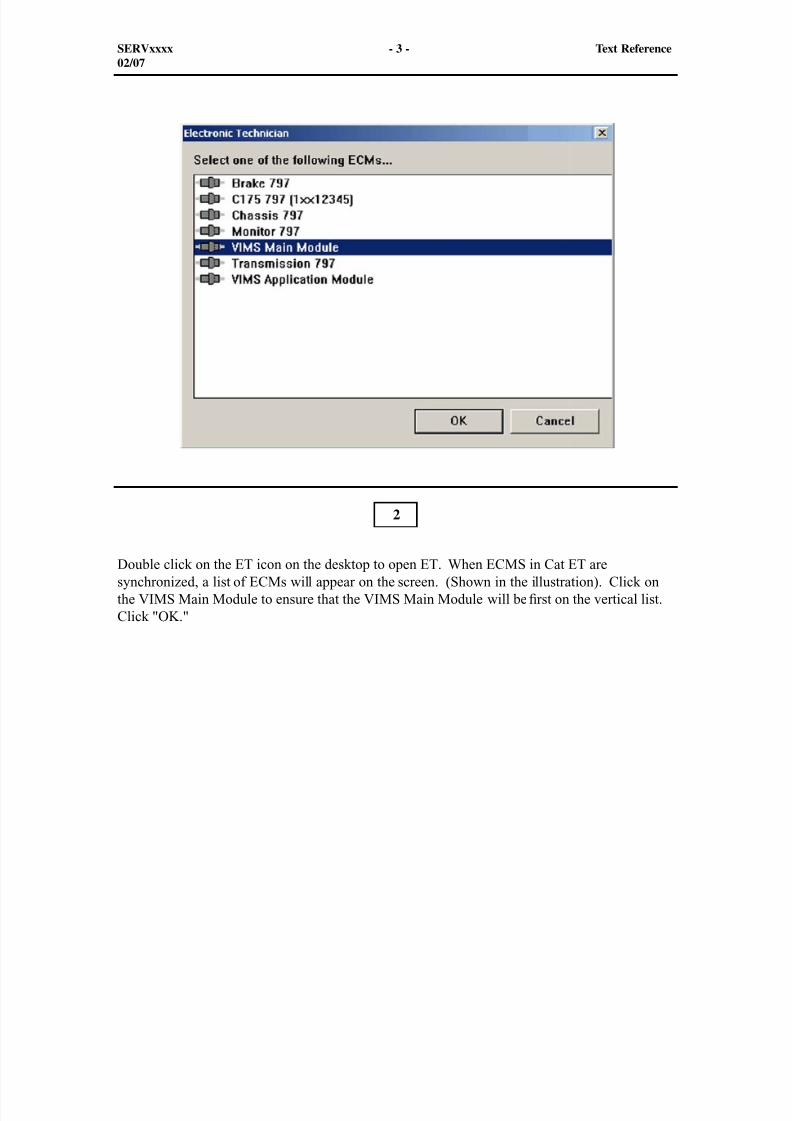
8/9/2019 797F HAA - Meeting Guide.pdf
http://slidepdf.com/reader/full/797f-haa-meeting-guidepdf 319/367
SERVxxxx - 3 - Text Reference02/07
Double click on the ET icon on the desktop to open ET. When ECMS in Cat ET aresynchronized, a list of ECMs will appear on the screen. (Shown in the illustration). Click onthe VIMS Main Module to ensure that the VIMS Main Module will be rst on the vertical list.Click "OK."
2
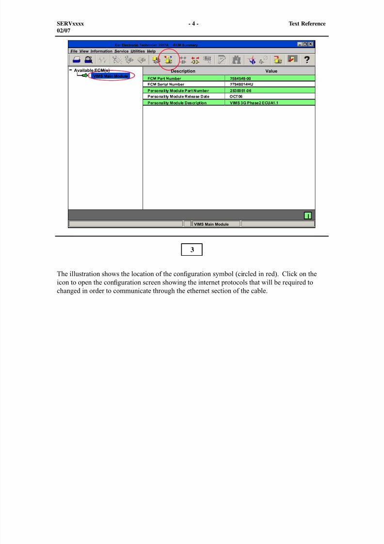
8/9/2019 797F HAA - Meeting Guide.pdf
http://slidepdf.com/reader/full/797f-haa-meeting-guidepdf 320/367
SERVxxxx - 4 - Text Reference02/07
3
The illustration shows the location of the con guration symbol (circled in red). Click on theicon to open the con guration screen showing the internet protocols that will be required tochanged in order to communicate through the ethernet section of the cable.
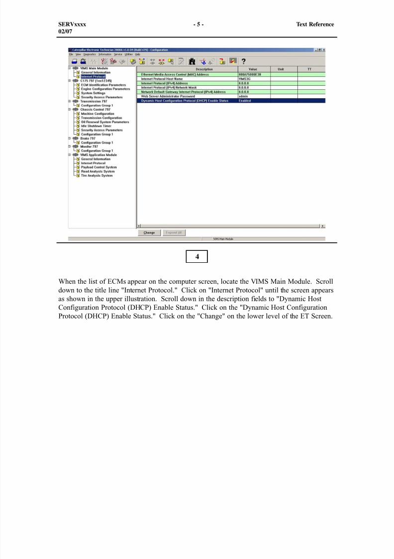
8/9/2019 797F HAA - Meeting Guide.pdf
http://slidepdf.com/reader/full/797f-haa-meeting-guidepdf 321/367
When the list of ECMs appear on the computer screen, locate the VIMS Main Module. Scrolldown to the title line "Internet Protocol." Click on "Internet Protocol" until the screen appearsas shown in the upper illustration. Scroll down in the description fields to "Dynamic HostConfiguration Protocol (DHCP) Enable Status." Click on the "Dynamic Host ConfigurationProtocol (DHCP) Enable Status." Click on the "Change" on the lower level of the ET Screen.
4
SERVxxxx - 5 - Text Reference02/07

8/9/2019 797F HAA - Meeting Guide.pdf
http://slidepdf.com/reader/full/797f-haa-meeting-guidepdf 322/367
SERVxxxx - 6 - Text Reference02/07
When the screen in the lower illustration appears, proceed to the "New Value:" drop down boxuntil Disabled appears. Then, click on the "OK" button.
5
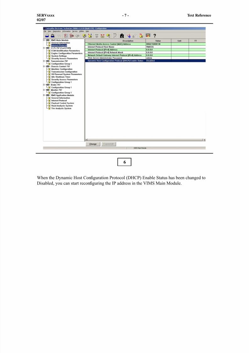
8/9/2019 797F HAA - Meeting Guide.pdf
http://slidepdf.com/reader/full/797f-haa-meeting-guidepdf 323/367
SERVxxxx - 7 - Text Reference02/07
When the Dynamic Host Con guration Protocol (DHCP) Enable Status has been changed toDisabled, you can start recon guring the IP address in the VIMS Main Module.
6
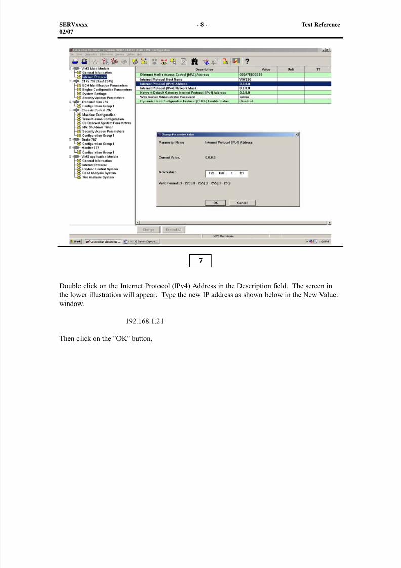
8/9/2019 797F HAA - Meeting Guide.pdf
http://slidepdf.com/reader/full/797f-haa-meeting-guidepdf 324/367
SERVxxxx - 8 - Text Reference02/07
Double click on the Internet Protocol (IPv4) Address in the Description field. The screen inthe lower illustration will appear. Type the new IP address as shown below in the New Value:window.
192.168.1.21
Then click on the "OK" button.
7
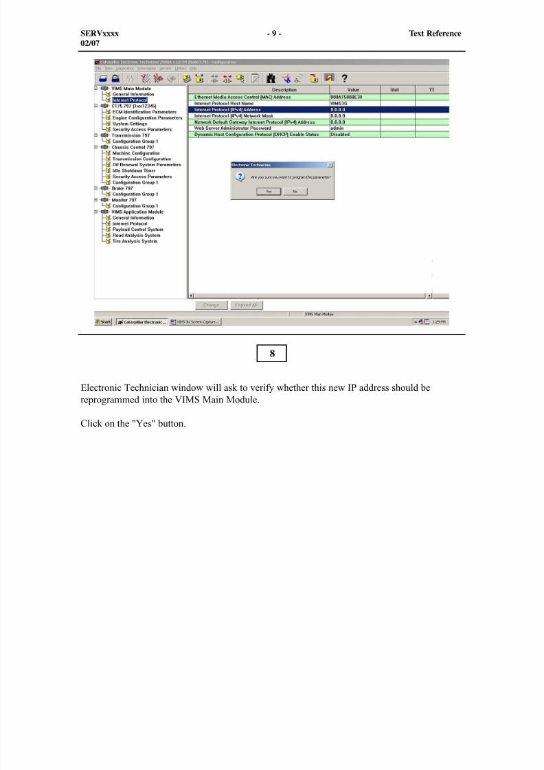
8/9/2019 797F HAA - Meeting Guide.pdf
http://slidepdf.com/reader/full/797f-haa-meeting-guidepdf 325/367
SERVxxxx - 9 - Text Reference02/07
Electronic Technician window will ask to verify whether this new IP address should bereprogrammed into the VIMS Main Module.
Click on the "Yes" button.
8
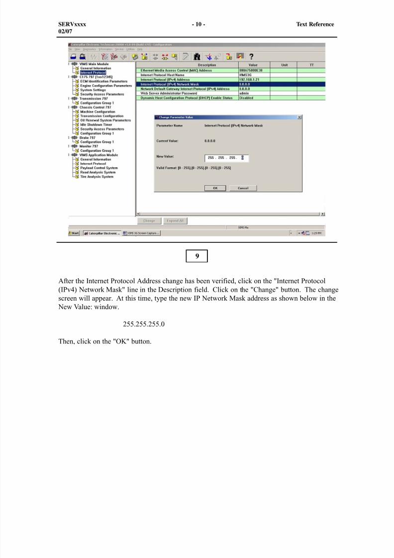
8/9/2019 797F HAA - Meeting Guide.pdf
http://slidepdf.com/reader/full/797f-haa-meeting-guidepdf 326/367
SERVxxxx - 10 - Text Reference02/07
After the Internet Protocol Address change has been verified, click on the "Internet Protocol(IPv4) Network Mask" line in the Description field. Click on the "Change" button. The changescreen will appear. At this time, type the new IP Network Mask address as shown below in the
New Value: window.
255.255.255.0
Then, click on the "OK" button.
9
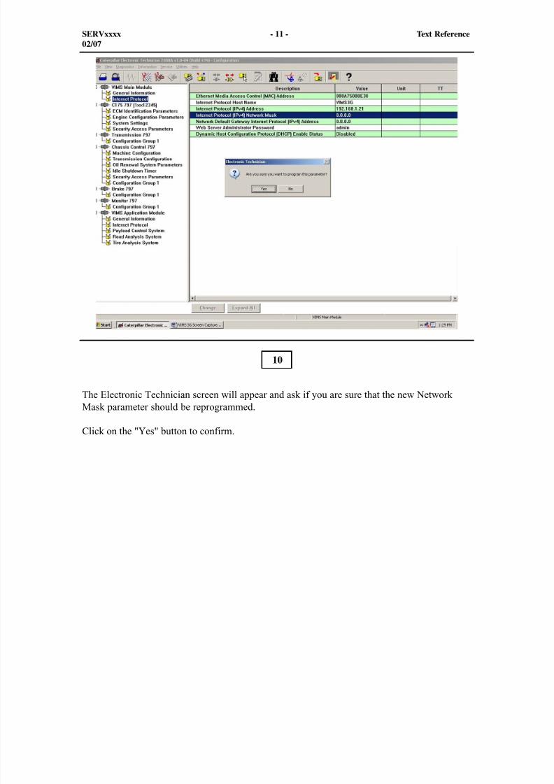
8/9/2019 797F HAA - Meeting Guide.pdf
http://slidepdf.com/reader/full/797f-haa-meeting-guidepdf 327/367
SERVxxxx - 11 - Text Reference02/07
The Electronic Technician screen will appear and ask if you are sure that the new NetworkMask parameter should be reprogrammed.
Click on the "Yes" button to confirm.
10
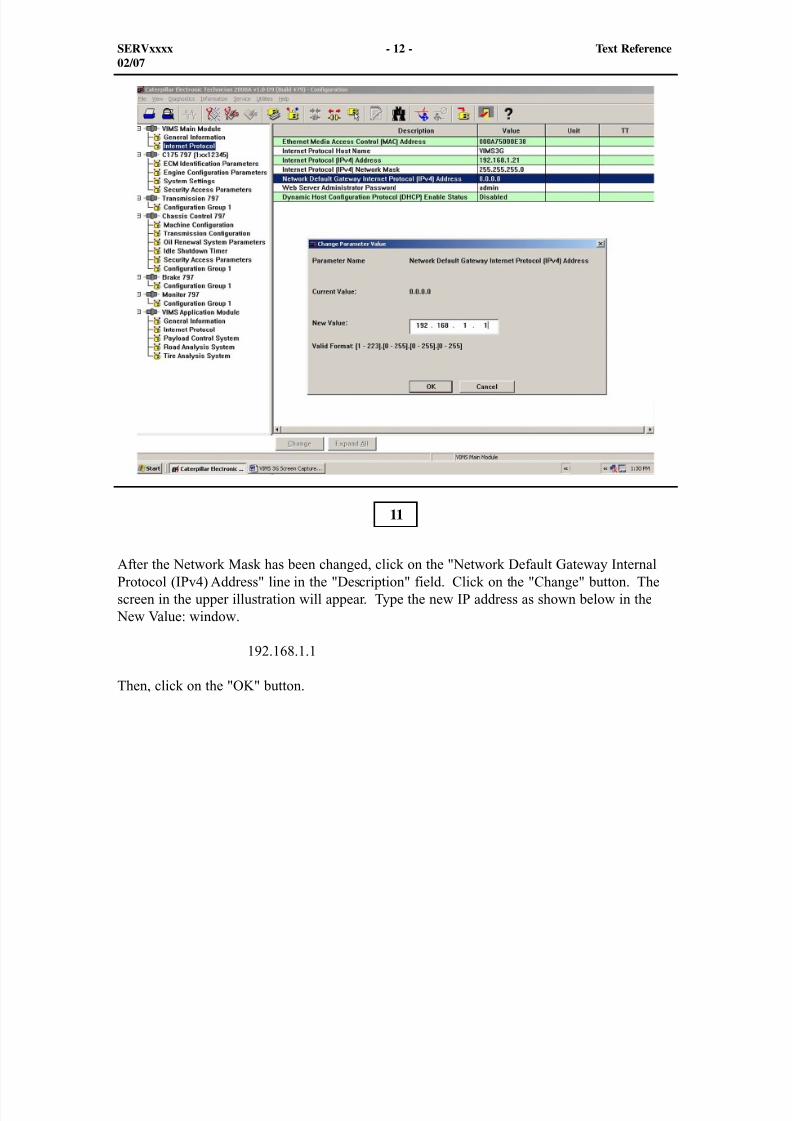
8/9/2019 797F HAA - Meeting Guide.pdf
http://slidepdf.com/reader/full/797f-haa-meeting-guidepdf 328/367
SERVxxxx - 12 - Text Reference02/07
After the Network Mask has been changed, click on the "Network Default Gateway InternalProtocol (IPv4) Address" line in the "Description" field. Click on the "Change" button. Thescreen in the upper illustration will appear. Type the new IP address as shown below in the
New Value: window.
192.168.1.1
Then, click on the "OK" button.
11
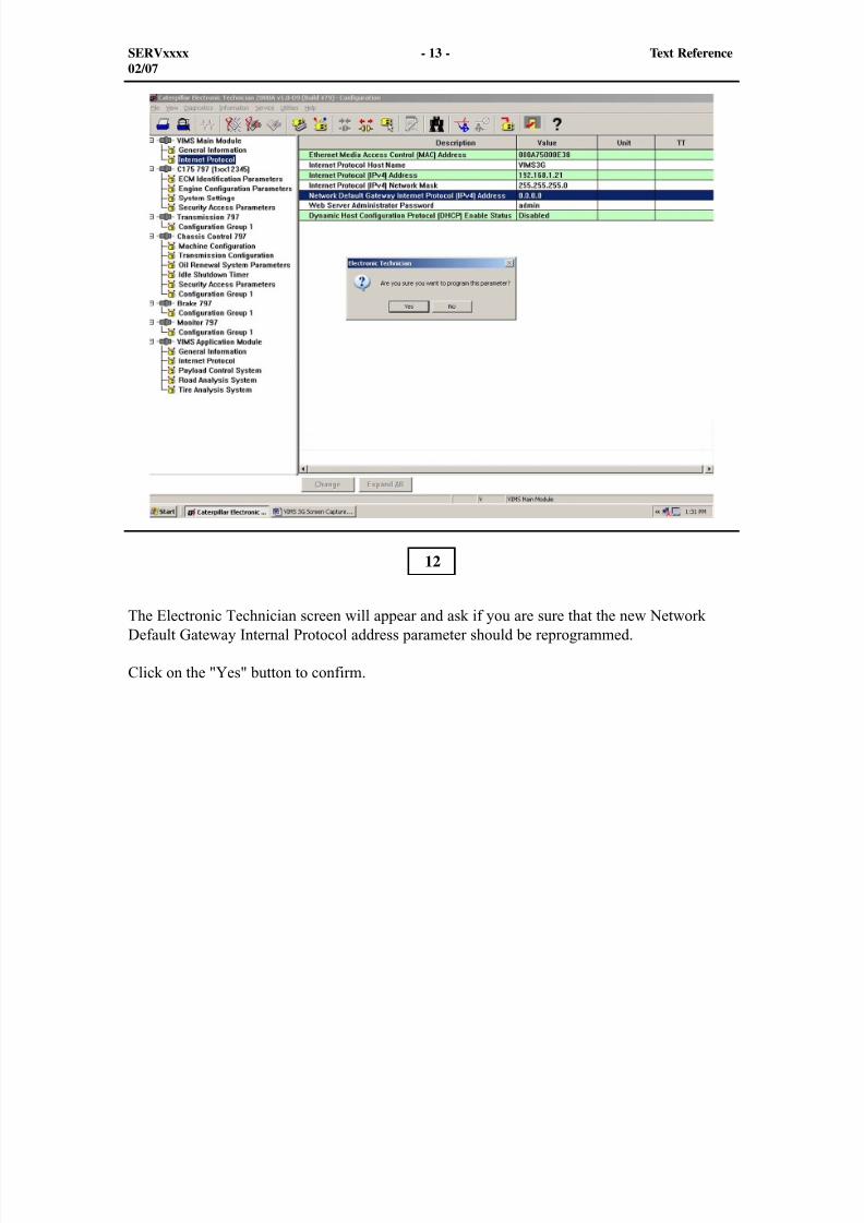
8/9/2019 797F HAA - Meeting Guide.pdf
http://slidepdf.com/reader/full/797f-haa-meeting-guidepdf 329/367
SERVxxxx - 13 - Text Reference02/07
The Electronic Technician screen will appear and ask if you are sure that the new NetworkDefault Gateway Internal Protocol address parameter should be reprogrammed.
Click on the "Yes" button to confirm.
12
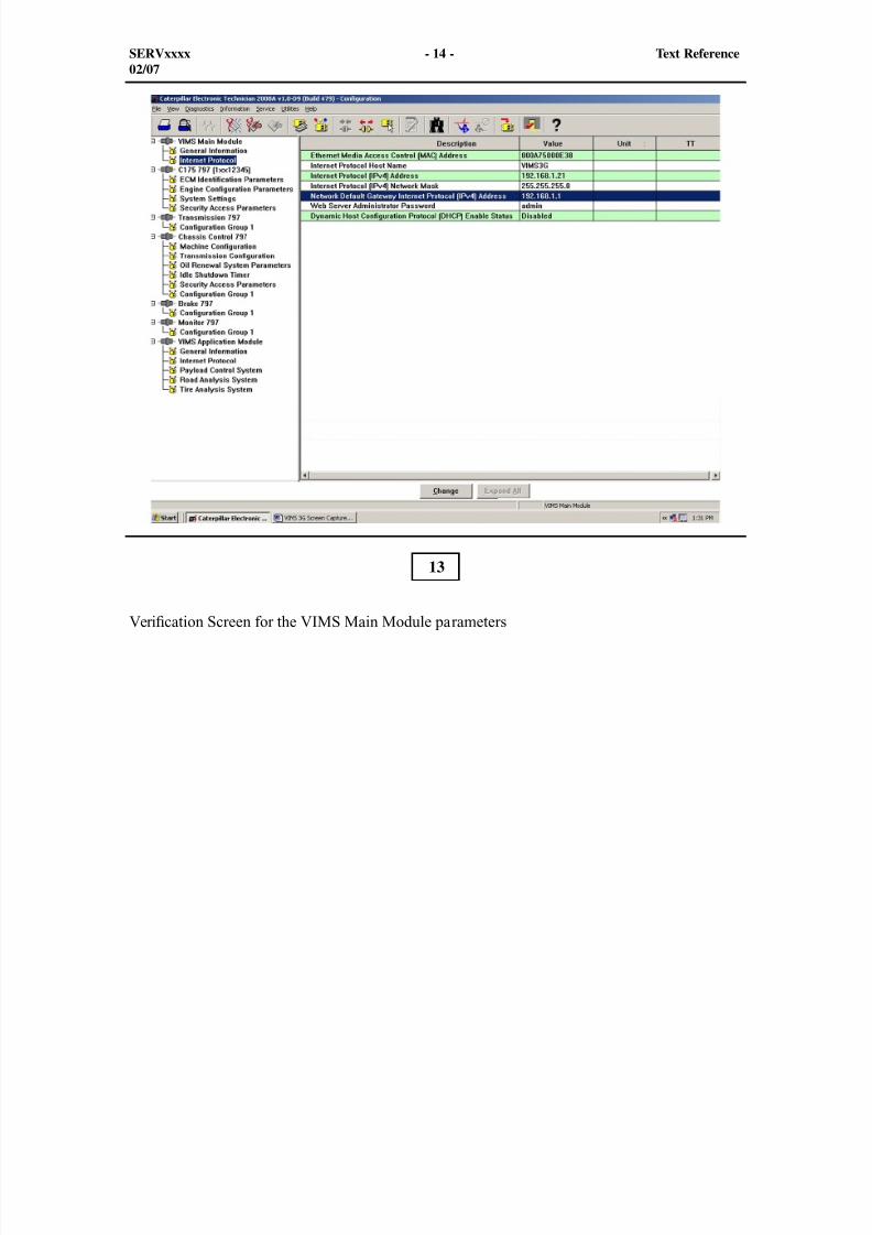
8/9/2019 797F HAA - Meeting Guide.pdf
http://slidepdf.com/reader/full/797f-haa-meeting-guidepdf 330/367
SERVxxxx - 14 - Text Reference02/07
Veri cation Screen for the VIMS Main Module parameters
13
8/9/2019 797F HAA - Meeting Guide.pdf
http://slidepdf.com/reader/full/797f-haa-meeting-guidepdf 331/367
SERVxxxx - 15 - Text Reference02/07
14
Internet Protocols In The Application Module
Connecting Cat ET to the truck for resetting the Internet Protocols (IP address). Beforeattempting to connect with the VIMS Application module, ensure that the computer being usedis equipped with Caterpillar ET Version 2007C or later. Connect the new 305-5528 - Cable tothe VIMS port in the cab and the serial plug of the cable to the serial port on the backside of theoff-board computer. The Ethernet cable is not plugged in at this time.
To communicate between the off-board computer and the VIMS modules, there are somedirections that need to be followed.
Double click on the Cat ET icon on the off-board computer and follow the directions on thescreen. When the connections are correct, the screen will show a vertical list of the truckECMs.
The first step is to change the internet protocols in the VIMS Application Module. Follow thedirections to complete the setup.
NOTE: To change the VIMS Application Module IP address, the Dynamic HostConfiguration Protocol Enable Status must be reprogrammed to be Disabled. Followthe instructions for disabling the DHCP that is in the VIMS Main Module section.

8/9/2019 797F HAA - Meeting Guide.pdf
http://slidepdf.com/reader/full/797f-haa-meeting-guidepdf 332/367
The illustration shows the location of the con guration symbol (circled in red). Click on theicon to open the con guration screen showing the internet protocols that will be required tochanged in order to communicate through the ethernet section of the cable. Refer to Page 4
SERVxxxx - 16 - Text Reference02/07
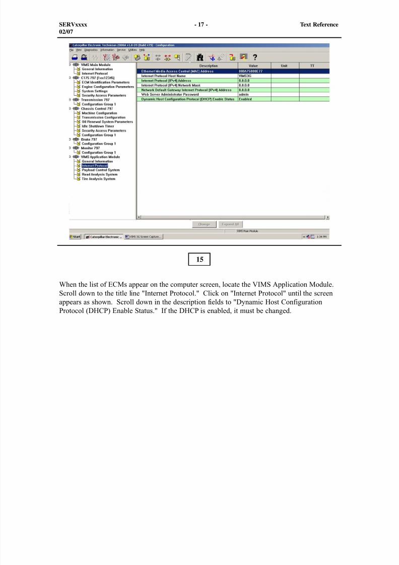
8/9/2019 797F HAA - Meeting Guide.pdf
http://slidepdf.com/reader/full/797f-haa-meeting-guidepdf 333/367
SERVxxxx - 17 - Text Reference02/07
When the list of ECMs appear on the computer screen, locate the VIMS Application Module.Scroll down to the title line "Internet Protocol." Click on "Internet Protocol" until the screenappears as shown. Scroll down in the description fields to "Dynamic Host ConfigurationProtocol (DHCP) Enable Status." If the DHCP is enabled, it must be changed.
15
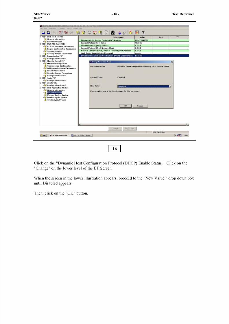
8/9/2019 797F HAA - Meeting Guide.pdf
http://slidepdf.com/reader/full/797f-haa-meeting-guidepdf 334/367
SERVxxxx - 18 - Text Reference02/07
Click on the "Dynamic Host Configuration Protocol (DHCP) Enable Status." Click on the"Change" on the lower level of the ET Screen.
When the screen in the lower illustration appears, proceed to the "New Value:" drop down boxuntil Disabled appears.
Then, click on the "OK" button.
16
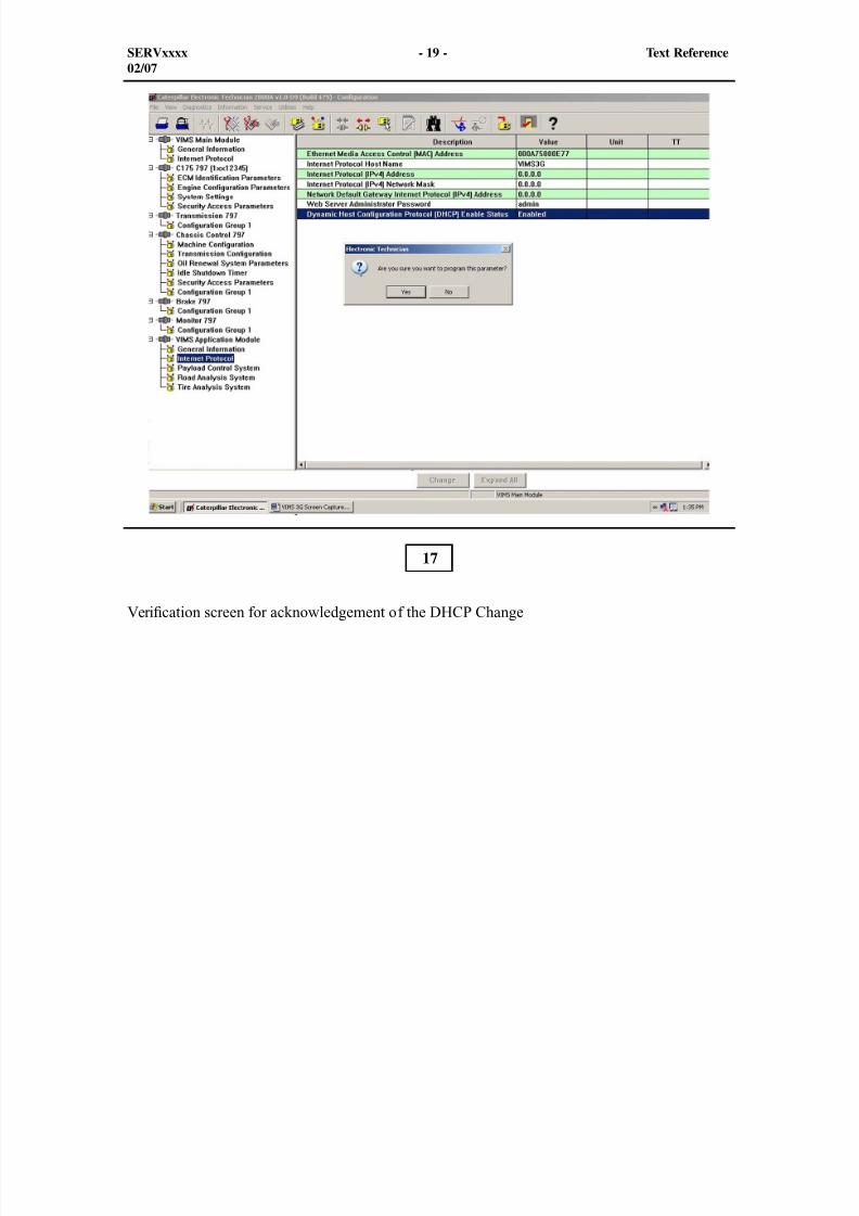
8/9/2019 797F HAA - Meeting Guide.pdf
http://slidepdf.com/reader/full/797f-haa-meeting-guidepdf 335/367
SERVxxxx - 19 - Text Reference02/07
Veri cation screen for acknowledgement of the DHCP Change
17
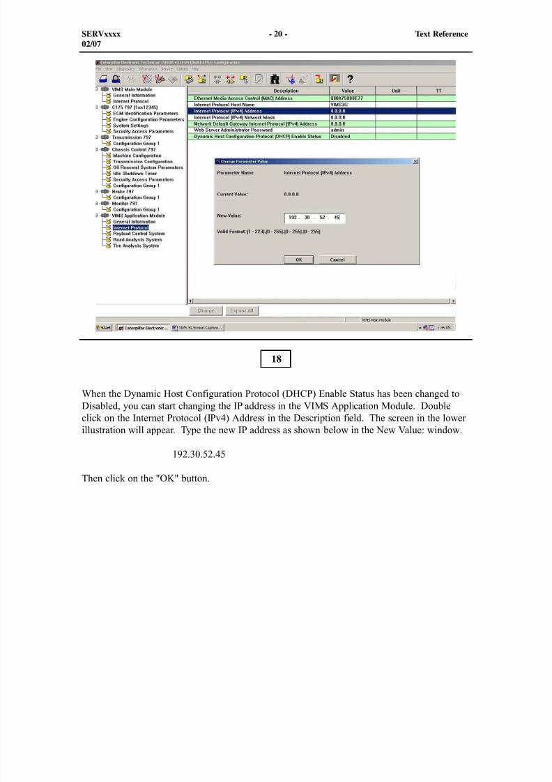
8/9/2019 797F HAA - Meeting Guide.pdf
http://slidepdf.com/reader/full/797f-haa-meeting-guidepdf 336/367
SERVxxxx - 20 - Text Reference02/07
When the Dynamic Host Configuration Protocol (DHCP) Enable Status has been changed toDisabled, you can start changing the IP address in the VIMS Application Module. Doubleclick on the Internet Protocol (IPv4) Address in the Description field. The screen in the lowerillustration will appear. Type the new IP address as shown below in the New Value: window.
192.30.52.45
Then click on the "OK" button.
18
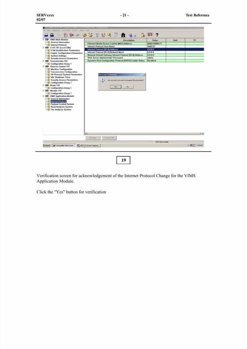
8/9/2019 797F HAA - Meeting Guide.pdf
http://slidepdf.com/reader/full/797f-haa-meeting-guidepdf 337/367
SERVxxxx - 21 - Text Reference02/07
Verification screen for acknowledgement of the Internet Protocol Change for the VIMSApplication Module.
Click the "Yes" button for verification
19
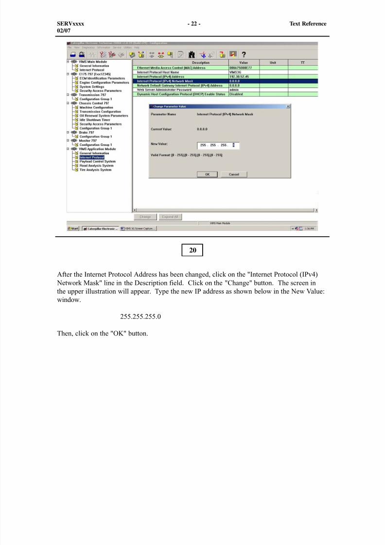
8/9/2019 797F HAA - Meeting Guide.pdf
http://slidepdf.com/reader/full/797f-haa-meeting-guidepdf 338/367
SERVxxxx - 22 - Text Reference02/07
After the Internet Protocol Address has been changed, click on the "Internet Protocol (IPv4) Network Mask" line in the Description field. Click on the "Change" button. The screen inthe upper illustration will appear. Type the new IP address as shown below in the New Value:window.
255.255.255.0
Then, click on the "OK" button.
20
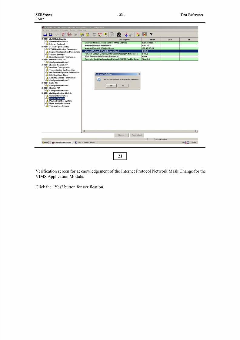
8/9/2019 797F HAA - Meeting Guide.pdf
http://slidepdf.com/reader/full/797f-haa-meeting-guidepdf 339/367
SERVxxxx - 23 - Text Reference02/07
Verification screen for acknowledgement of the Internet Protocol Network Mask Change for theVIMS Application Module.
Click the "Yes" button for verification.
21
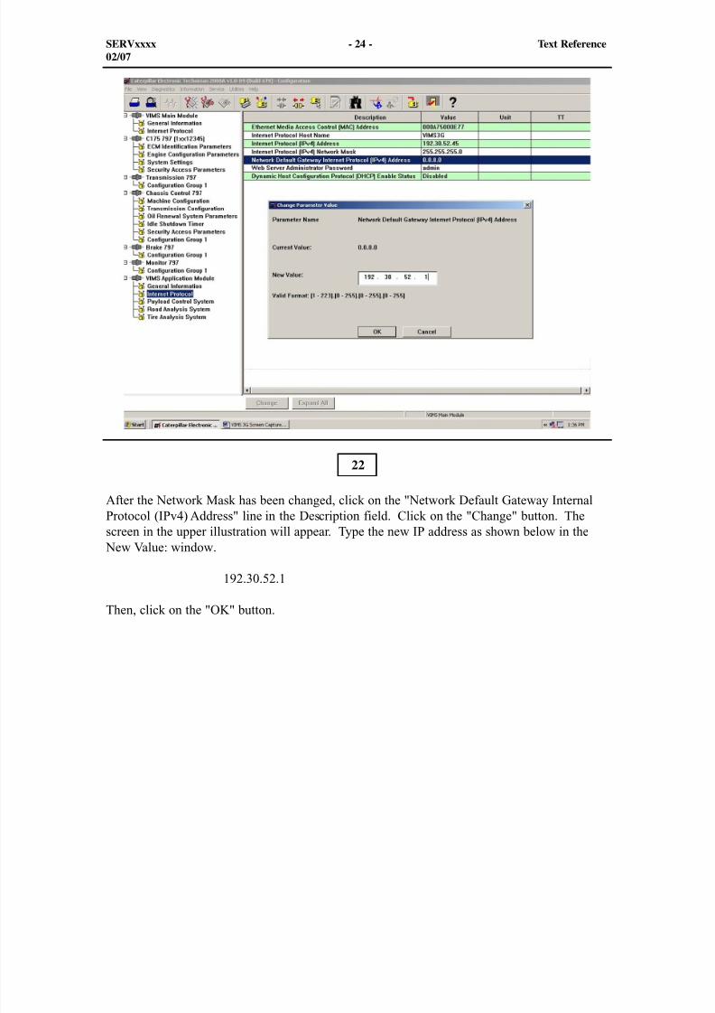
8/9/2019 797F HAA - Meeting Guide.pdf
http://slidepdf.com/reader/full/797f-haa-meeting-guidepdf 340/367
SERVxxxx - 24 - Text Reference02/07
After the Network Mask has been changed, click on the "Network Default Gateway InternalProtocol (IPv4) Address" line in the Description field. Click on the "Change" button. Thescreen in the upper illustration will appear. Type the new IP address as shown below in the
New Value: window.
192.30.52.1
Then, click on the "OK" button.
22
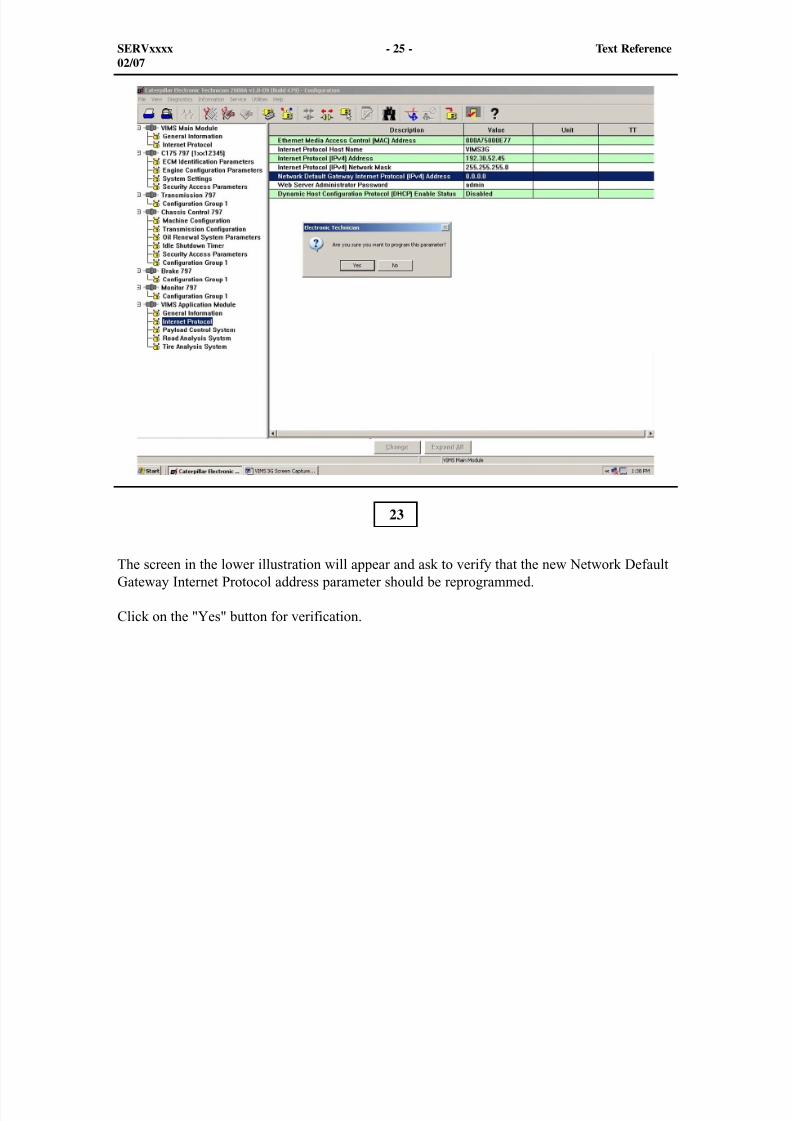
8/9/2019 797F HAA - Meeting Guide.pdf
http://slidepdf.com/reader/full/797f-haa-meeting-guidepdf 341/367
SERVxxxx - 25 - Text Reference02/07
The screen in the lower illustration will appear and ask to verify that the new Network DefaultGateway Internet Protocol address parameter should be reprogrammed.
Click on the "Yes" button for verification.
23
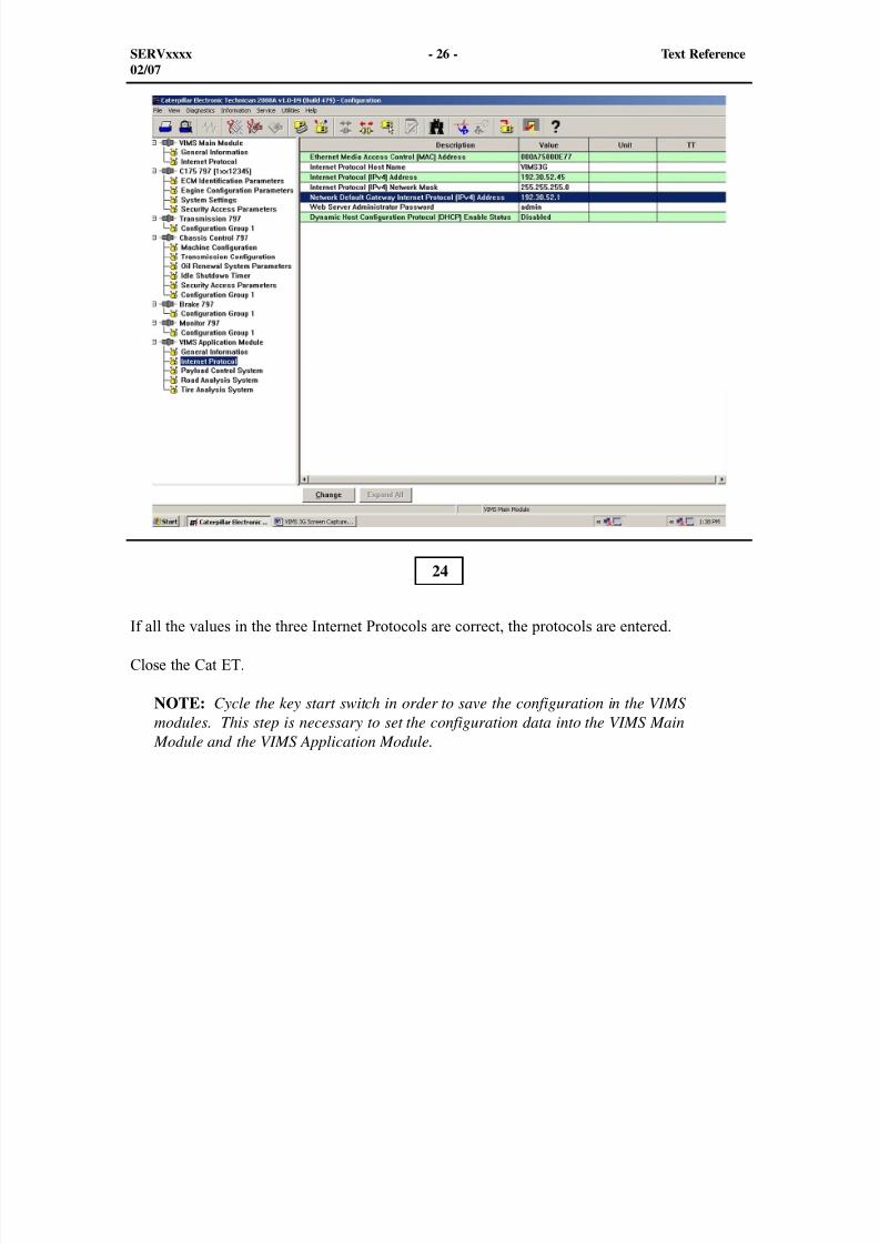
8/9/2019 797F HAA - Meeting Guide.pdf
http://slidepdf.com/reader/full/797f-haa-meeting-guidepdf 342/367
SERVxxxx - 26 - Text Reference02/07
If all the values in the three Internet Protocols are correct, the protocols are entered.
Close the Cat ET.
NOTE: Cycle the key start switch in order to save the configuration in the VIMSmodules. This step is necessary to set the configuration data into the VIMS Main
Module and the VIMS Application Module.
24
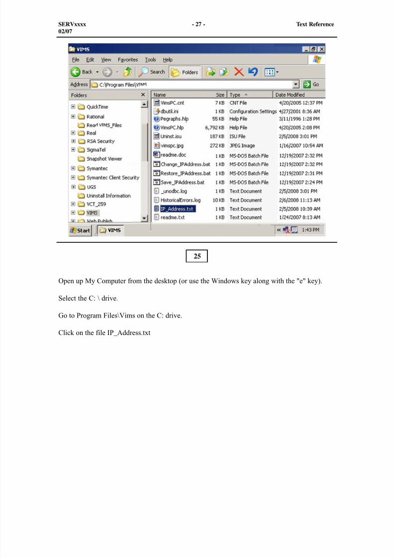
8/9/2019 797F HAA - Meeting Guide.pdf
http://slidepdf.com/reader/full/797f-haa-meeting-guidepdf 343/367
SERVxxxx - 27 - Text Reference02/07
Open up My Computer from the desktop (or use the Windows key along with the "e" key).
Select the C: \ drive.
Go to Program Files\Vims on the C: drive.
Click on the file IP_Address.txt
25
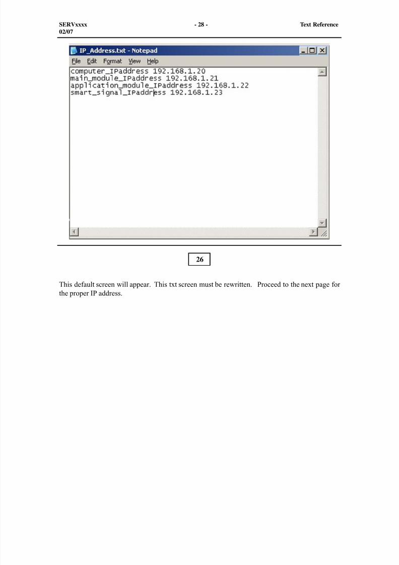
8/9/2019 797F HAA - Meeting Guide.pdf
http://slidepdf.com/reader/full/797f-haa-meeting-guidepdf 344/367
SERVxxxx - 28 - Text Reference02/07
This default screen will appear. This txt screen must be rewritten. Proceed to the next page forthe proper IP address.
26
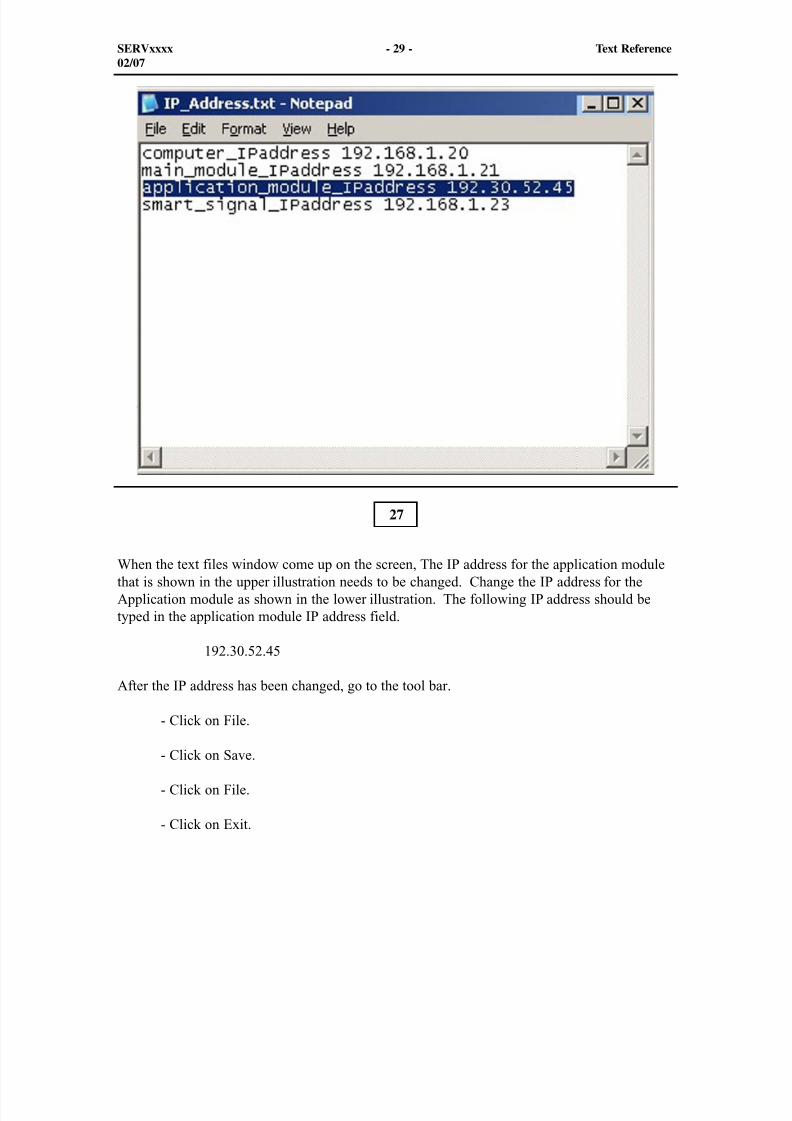
8/9/2019 797F HAA - Meeting Guide.pdf
http://slidepdf.com/reader/full/797f-haa-meeting-guidepdf 345/367
SERVxxxx - 29 - Text Reference02/07
When the text files window come up on the screen, The IP address for the application modulethat is shown in the upper illustration needs to be changed. Change the IP address for theApplication module as shown in the lower illustration. The following IP address should betyped in the application module IP address field.
192.30.52.45
After the IP address has been changed, go to the tool bar.
- Click on File.
- Click on Save.
- Click on File.
- Click on Exit.
27
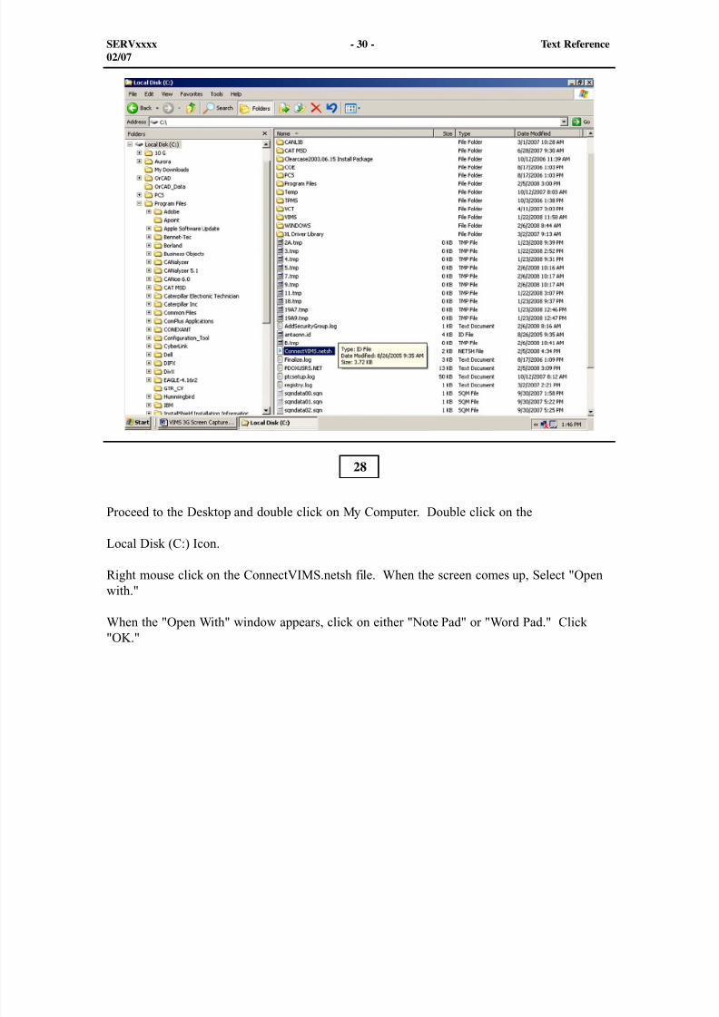
8/9/2019 797F HAA - Meeting Guide.pdf
http://slidepdf.com/reader/full/797f-haa-meeting-guidepdf 346/367
SERVxxxx - 30 - Text Reference02/07
Proceed to the Desktop and double click on My Computer. Double click on the
Local Disk (C:) Icon.
Right mouse click on the ConnectVIMS.netsh file. When the screen comes up, Select "Openwith."
When the "Open With" window appears, click on either "Note Pad" or "Word Pad." Click"OK."
28
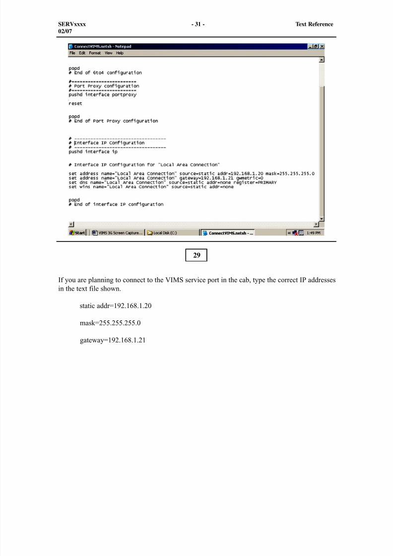
8/9/2019 797F HAA - Meeting Guide.pdf
http://slidepdf.com/reader/full/797f-haa-meeting-guidepdf 347/367
SERVxxxx - 31 - Text Reference02/07
If you are planning to connect to the VIMS service port in the cab, type the correct IP addressesin the text file shown.
static addr=192.168.1.20
mask=255.255.255.0
gateway=192.168.1.21
29
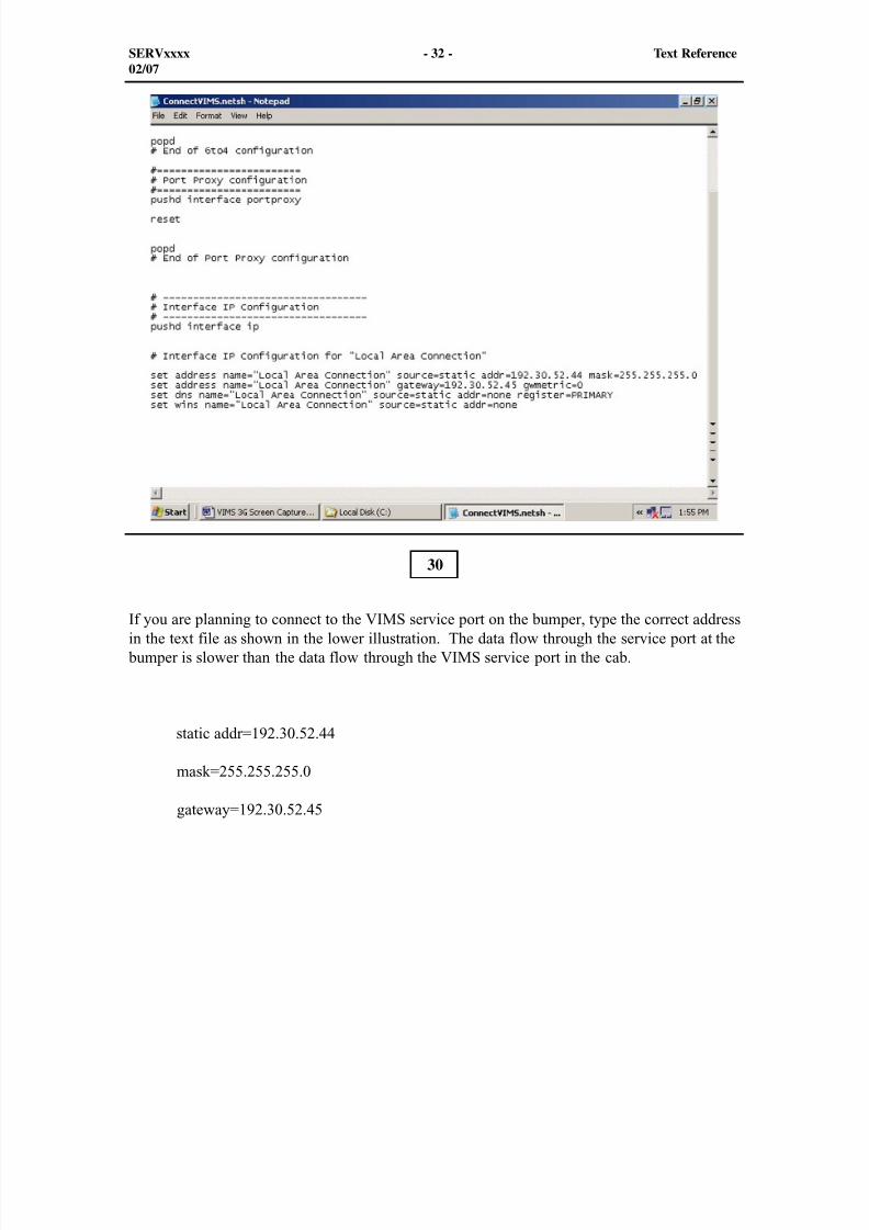
8/9/2019 797F HAA - Meeting Guide.pdf
http://slidepdf.com/reader/full/797f-haa-meeting-guidepdf 348/367
SERVxxxx - 32 - Text Reference02/07
If you are planning to connect to the VIMS service port on the bumper, type the correct addressin the text file as shown in the lower illustration. The data flow through the service port at the
bumper is slower than the data flow through the VIMS service port in the cab.
static addr=192.30.52.44
mask=255.255.255.0
gateway=192.30.52.45
30
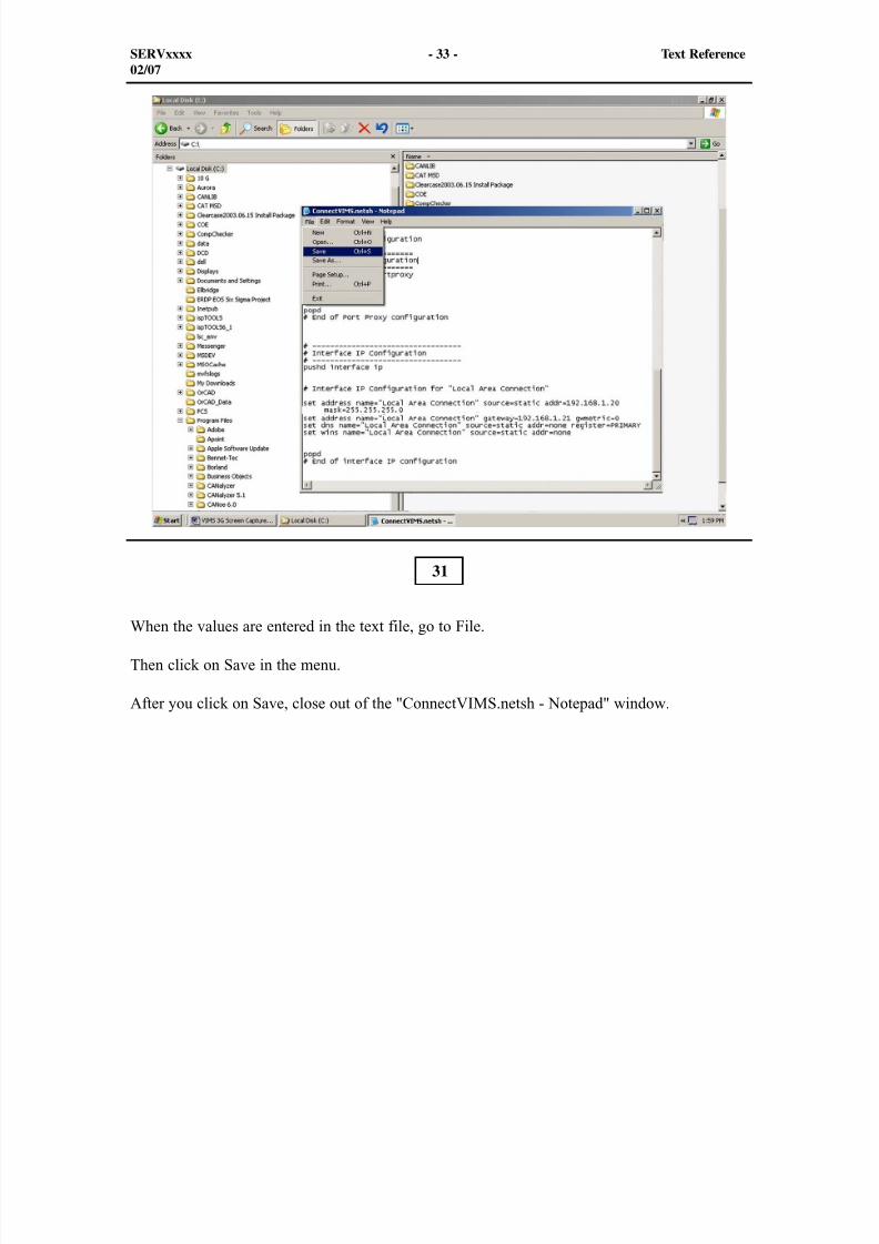
8/9/2019 797F HAA - Meeting Guide.pdf
http://slidepdf.com/reader/full/797f-haa-meeting-guidepdf 349/367
SERVxxxx - 33 - Text Reference02/07
When the values are entered in the text file, go to File.
Then click on Save in the menu.
After you click on Save, close out of the "ConnectVIMS.netsh - Notepad" window.
31
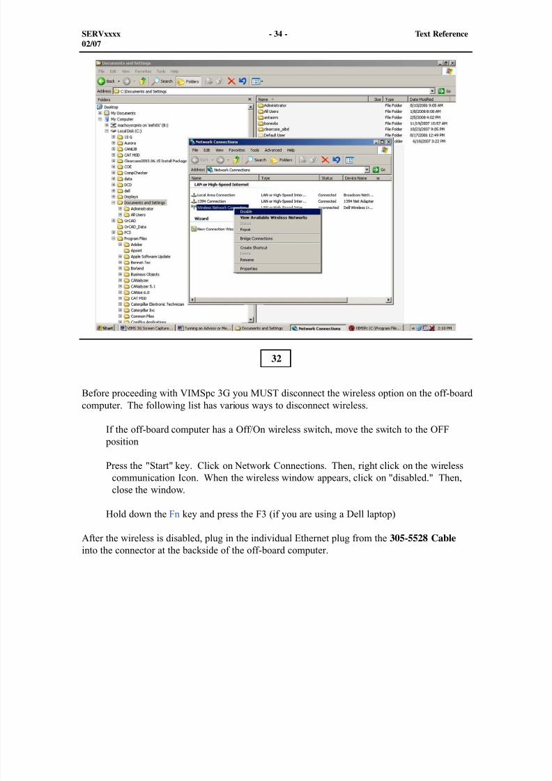
8/9/2019 797F HAA - Meeting Guide.pdf
http://slidepdf.com/reader/full/797f-haa-meeting-guidepdf 350/367
SERVxxxx - 34 - Text Reference02/07
Before proceeding with VIMSpc 3G you MUST disconnect the wireless option on the off-boardcomputer. The following list has various ways to disconnect wireless.
If the off-board computer has a Off/On wireless switch, move the switch to the OFF position
Press the "Start" key. Click on Network Connections. Then, right click on the wirelesscommunication Icon. When the wireless window appears, click on "disabled." Then,close the window.
Hold down the Fn key and press the F3 (if you are using a Dell laptop)
After the wireless is disabled, plug in the individual Ethernet plug from the 305-5528 Cable into the connector at the backside of the off-board computer.
32
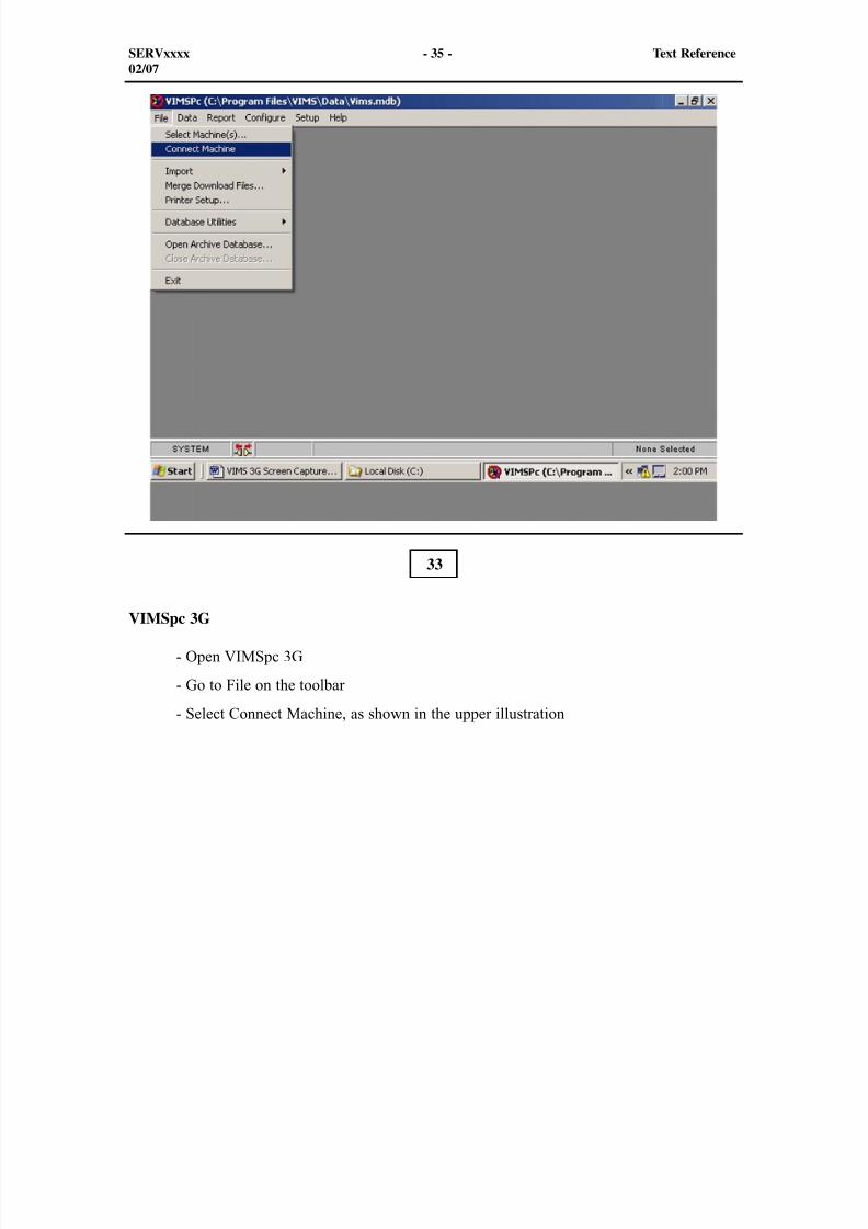
8/9/2019 797F HAA - Meeting Guide.pdf
http://slidepdf.com/reader/full/797f-haa-meeting-guidepdf 351/367
SERVxxxx - 35 - Text Reference02/07
33
VIMSpc 3G
- Open VIMSpc 3G
- Go to File on the toolbar
- Select Connect Machine, as shown in the upper illustration
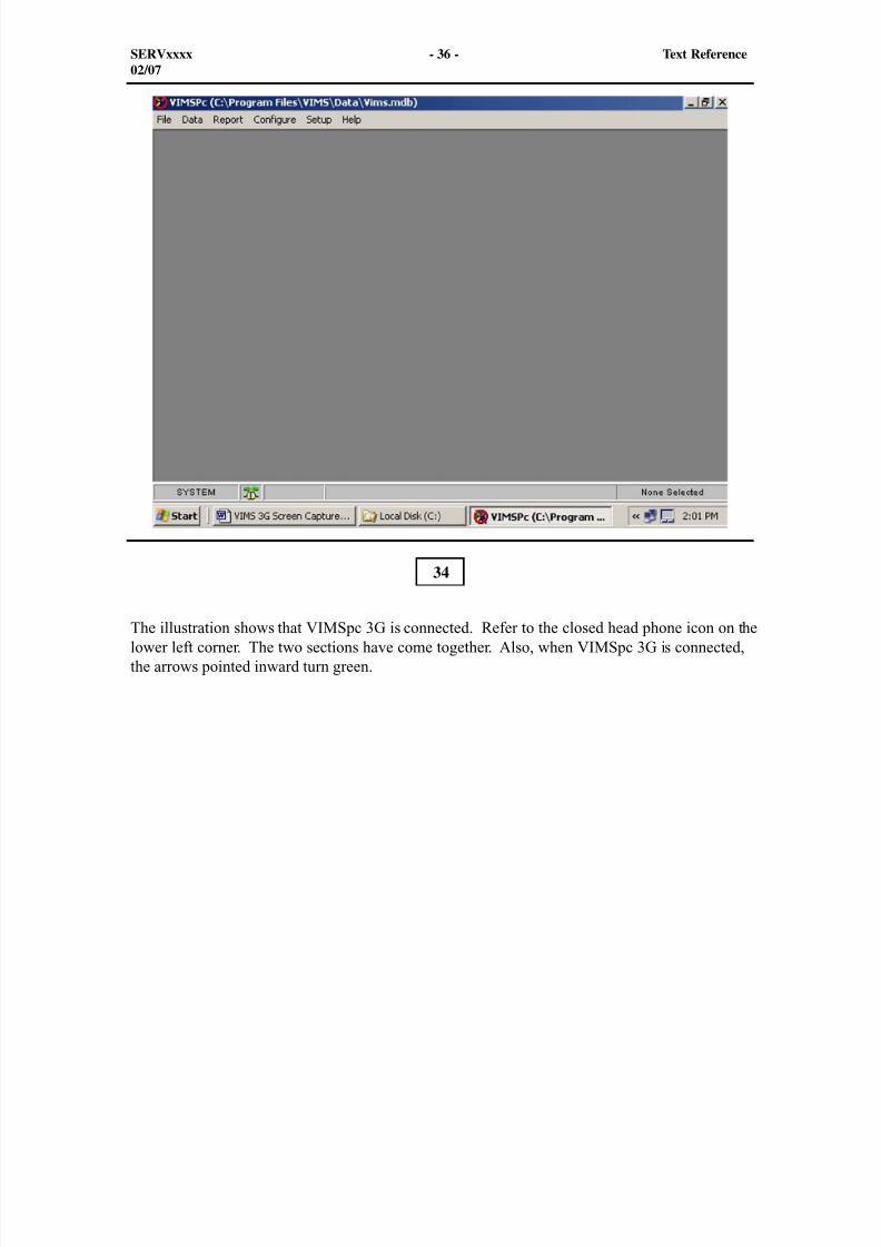
8/9/2019 797F HAA - Meeting Guide.pdf
http://slidepdf.com/reader/full/797f-haa-meeting-guidepdf 352/367
34
SERVxxxx - 36 - Text Reference02/07
The illustration shows that VIMSpc 3G is connected. Refer to the closed head phone icon on thelower left corner. The two sections have come together. Also, when VIMSpc 3G is connected,the arrows pointed inward turn green.
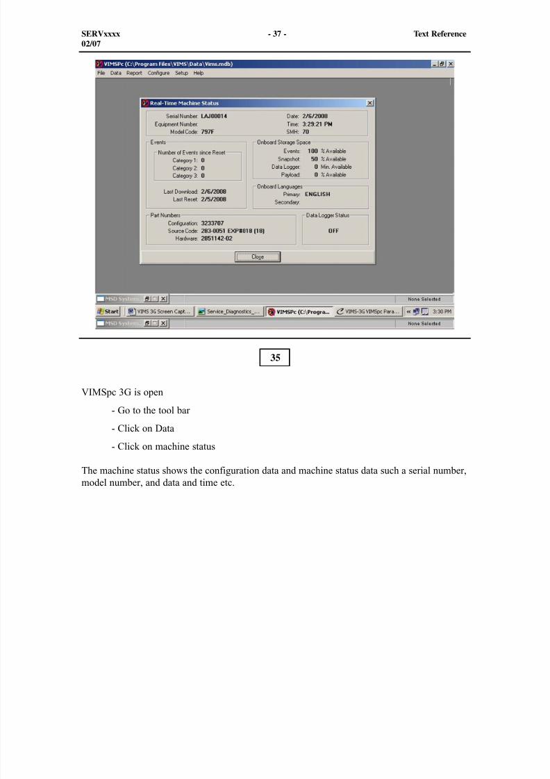
8/9/2019 797F HAA - Meeting Guide.pdf
http://slidepdf.com/reader/full/797f-haa-meeting-guidepdf 353/367
SERVxxxx - 37 - Text Reference02/07
35
VIMSpc 3G is open
- Go to the tool bar
- Click on Data
- Click on machine status
The machine status shows the configuration data and machine status data such a serial number,model number, and data and time etc.
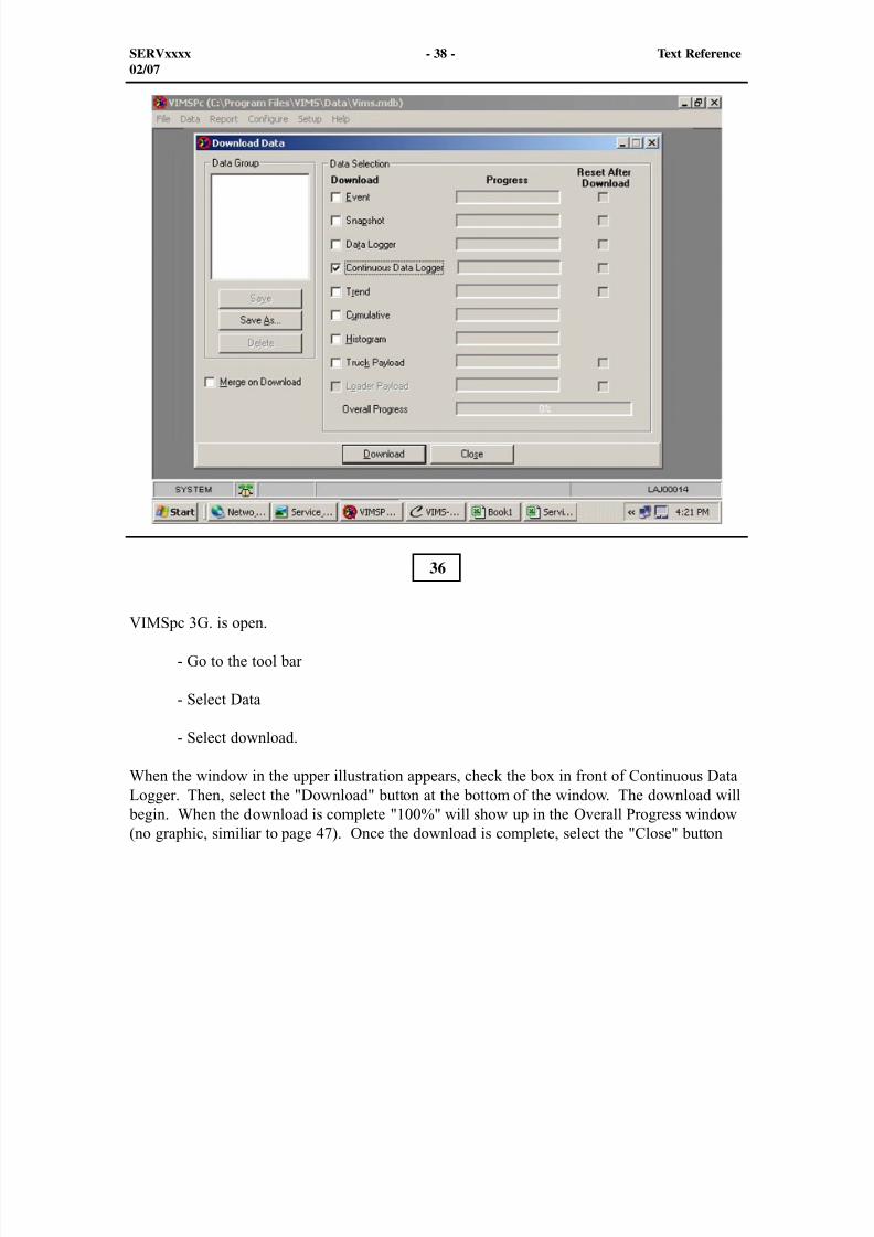
8/9/2019 797F HAA - Meeting Guide.pdf
http://slidepdf.com/reader/full/797f-haa-meeting-guidepdf 354/367
SERVxxxx - 38 - Text Reference02/07
VIMSpc 3G. is open.
- Go to the tool bar
- Select Data
- Select download.
When the window in the upper illustration appears, check the box in front of Continuous DataLogger. Then, select the "Download" button at the bottom of the window. The download will
begin. When the download is complete "100%" will show up in the Overall Progress window(no graphic, similiar to page 47). Once the download is complete, select the "Close" button
36
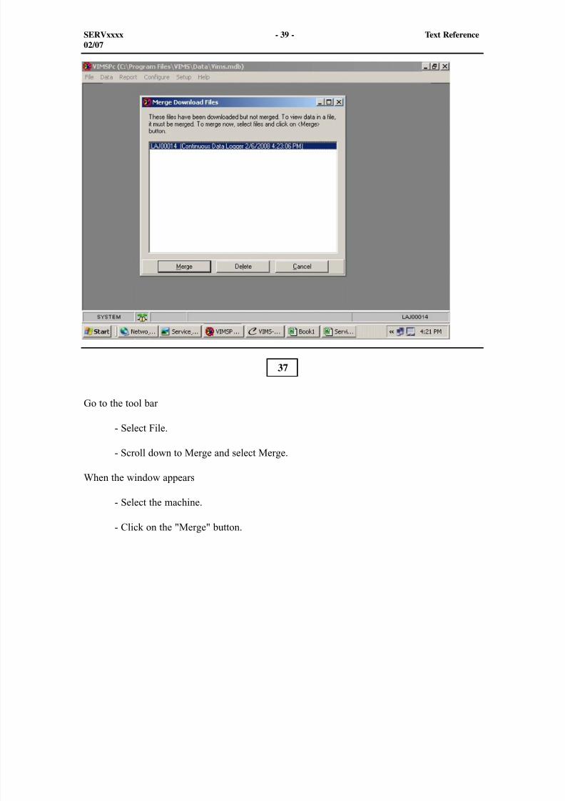
8/9/2019 797F HAA - Meeting Guide.pdf
http://slidepdf.com/reader/full/797f-haa-meeting-guidepdf 355/367
SERVxxxx - 39 - Text Reference02/07
Go to the tool bar
- Select File.
- Scroll down to Merge and select Merge.
When the window appears
- Select the machine.
- Click on the "Merge" button.
37
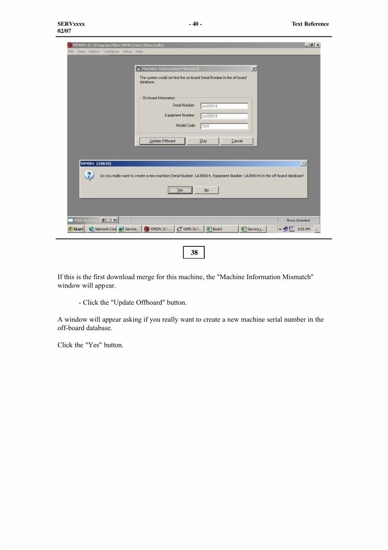
8/9/2019 797F HAA - Meeting Guide.pdf
http://slidepdf.com/reader/full/797f-haa-meeting-guidepdf 356/367
SERVxxxx - 40 - Text Reference02/07
If this is the first download merge for this machine, the "Machine Information Mismatch"window will appear.
- Click the "Update Offboard" button.
A window will appear asking if you really want to create a new machine serial number in theoff-board database.
Click the "Yes" button.
38
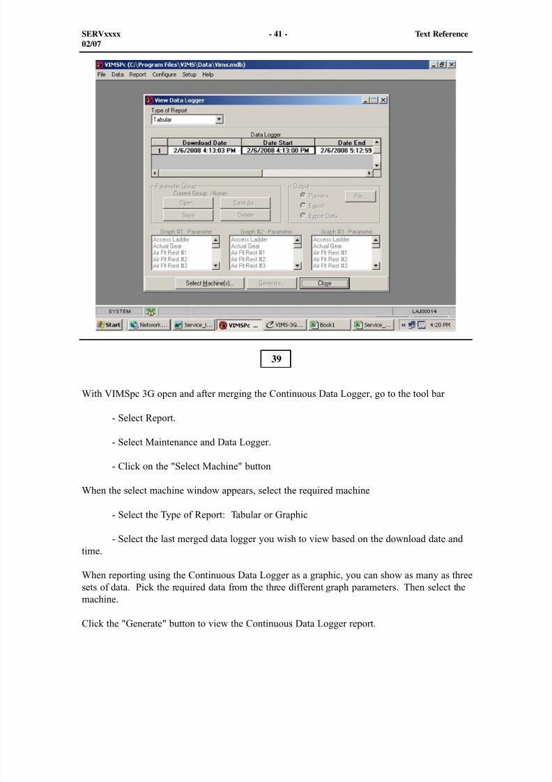
8/9/2019 797F HAA - Meeting Guide.pdf
http://slidepdf.com/reader/full/797f-haa-meeting-guidepdf 357/367
SERVxxxx - 41 - Text Reference02/07
With VIMSpc 3G open and after merging the Continuous Data Logger, go to the tool bar
- Select Report.
- Select Maintenance and Data Logger.
- Click on the "Select Machine" button
When the select machine window appears, select the required machine
- Select the Type of Report: Tabular or Graphic
- Select the last merged data logger you wish to view based on the download date andtime.
When reporting using the Continuous Data Logger as a graphic, you can show as many as threesets of data. Pick the required data from the three different graph parameters. Then select themachine.
Click the "Generate" button to view the Continuous Data Logger report.
39
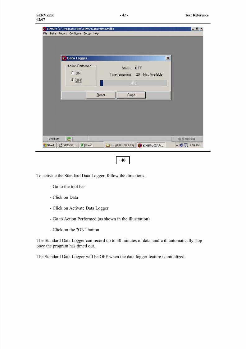
8/9/2019 797F HAA - Meeting Guide.pdf
http://slidepdf.com/reader/full/797f-haa-meeting-guidepdf 358/367
To activate the Standard Data Logger, follow the directions.
- Go to the tool bar
- Click on Data
- Click on Activate Data Logger
- Go to Action Performed (as shown in the illustration)
- Click on the "ON" button
The Standard Data Logger can record up to 30 minutes of data, and will automatically stoponce the program has timed out.
The Standard Data Logger will be OFF when the data logger feature is initialized.
40
SERVxxxx - 42 - Text Reference02/07
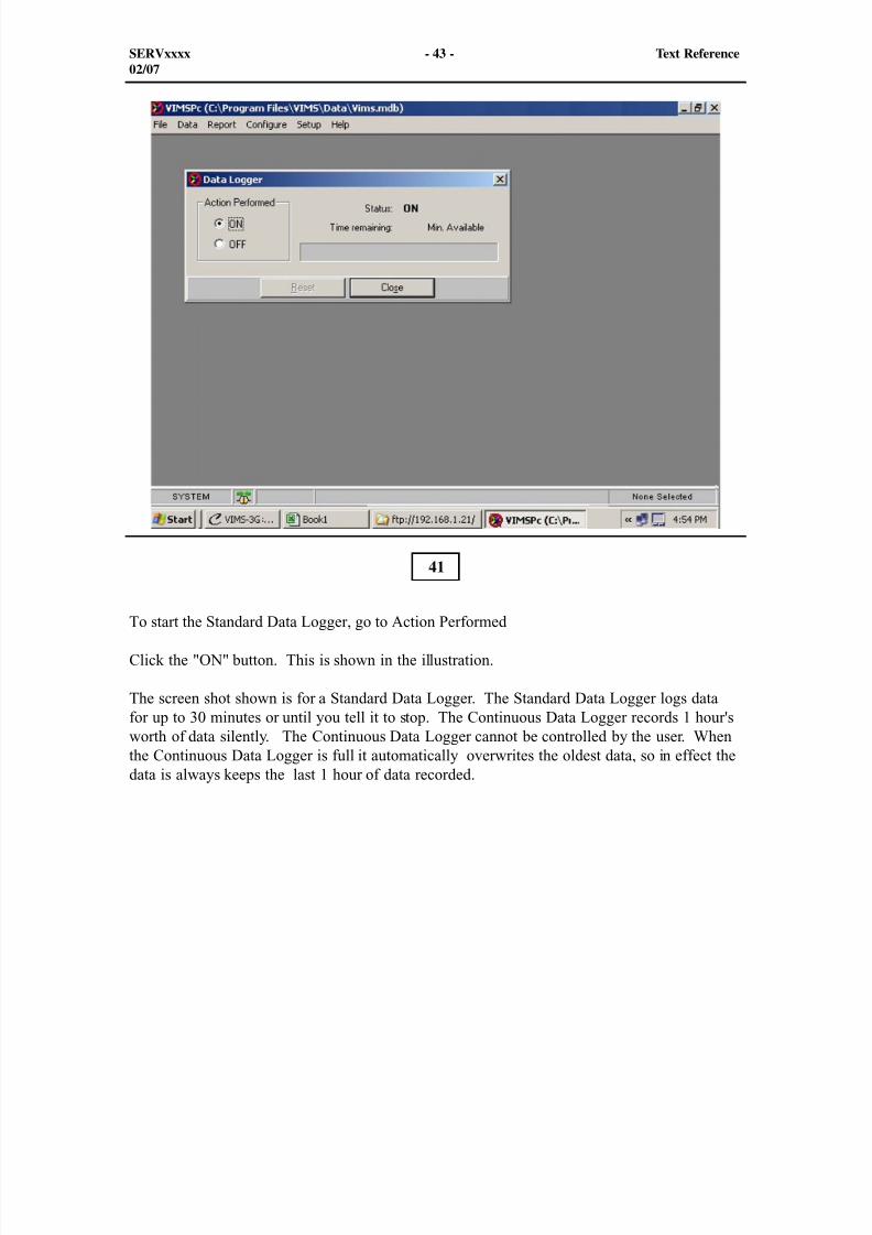
8/9/2019 797F HAA - Meeting Guide.pdf
http://slidepdf.com/reader/full/797f-haa-meeting-guidepdf 359/367
SERVxxxx - 43 - Text Reference02/07
To start the Standard Data Logger, go to Action Performed
Click the "ON" button. This is shown in the illustration.
The screen shot shown is for a Standard Data Logger. The Standard Data Logger logs datafor up to 30 minutes or until you tell it to stop. The Continuous Data Logger records 1 hour'sworth of data silently. The Continuous Data Logger cannot be controlled by the user. Whenthe Continuous Data Logger is full it automatically overwrites the oldest data, so in effect thedata is always keeps the last 1 hour of data recorded.
41
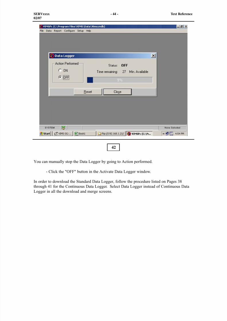
8/9/2019 797F HAA - Meeting Guide.pdf
http://slidepdf.com/reader/full/797f-haa-meeting-guidepdf 360/367
SERVxxxx - 44 - Text Reference02/07
You can manually stop the Data Logger by going to Action performed.
- Click the "OFF" button in the Activate Data Logger window.
In order to download the Standard Data Logger, follow the procedure listed on Pages 38through 41 for the Continuous Data Logger. Select Data Logger instead of Continuous DataLogger in all the download and merge screens.
42
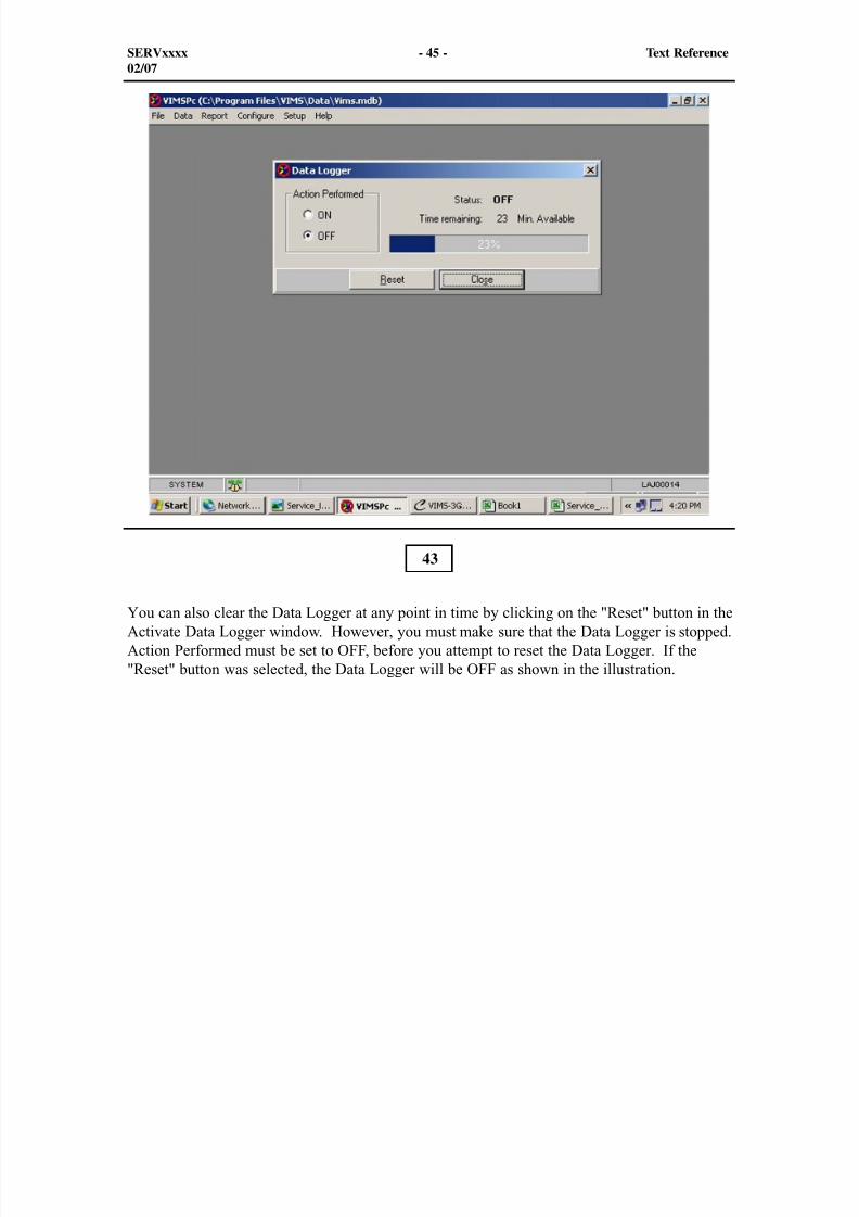
8/9/2019 797F HAA - Meeting Guide.pdf
http://slidepdf.com/reader/full/797f-haa-meeting-guidepdf 361/367
SERVxxxx - 45 - Text Reference02/07
You can also clear the Data Logger at any point in time by clicking on the "Reset" button in theActivate Data Logger window. However, you must make sure that the Data Logger is stopped.Action Performed must be set to OFF, before you attempt to reset the Data Logger. If the"Reset" button was selected, the Data Logger will be OFF as shown in the illustration.
43
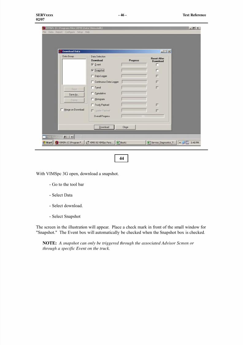
8/9/2019 797F HAA - Meeting Guide.pdf
http://slidepdf.com/reader/full/797f-haa-meeting-guidepdf 362/367
SERVxxxx - 46 - Text Reference02/07
With VIMSpc 3G open, download a snapshot.
- Go to the tool bar
- Select Data
- Select download.
- Select Snapshot
The screen in the illustration will appear. Place a check mark in front of the small window for"Snapshot." The Event box will automatically be checked when the Snapshot box is checked.
NOTE: A snapshot can only be triggered through the associated Advisor Screen orthrough a specific Event on the truck.
44
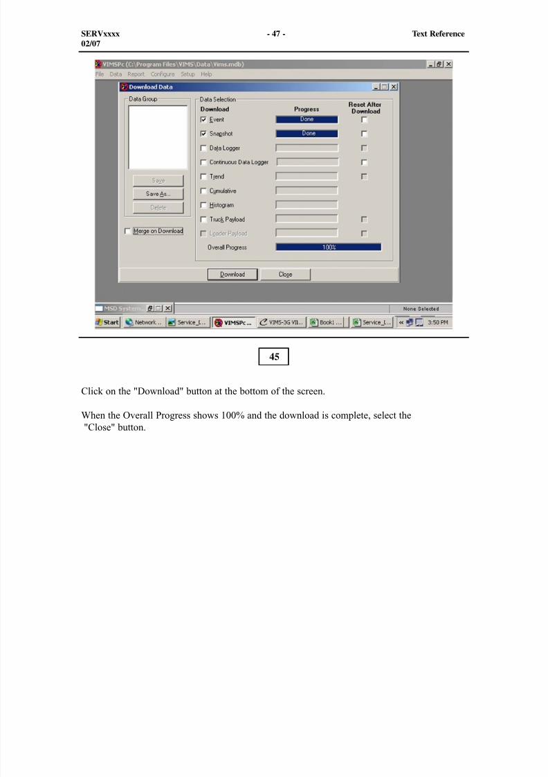
8/9/2019 797F HAA - Meeting Guide.pdf
http://slidepdf.com/reader/full/797f-haa-meeting-guidepdf 363/367
SERVxxxx - 47 - Text Reference02/07
Click on the "Download" button at the bottom of the screen.
When the Overall Progress shows 100% and the download is complete, select the "Close" button.
45
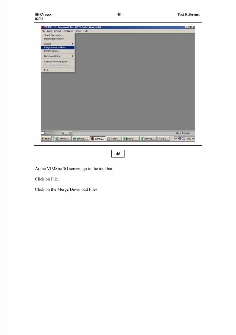
8/9/2019 797F HAA - Meeting Guide.pdf
http://slidepdf.com/reader/full/797f-haa-meeting-guidepdf 364/367
SERVxxxx - 48 - Text Reference02/07
At the VIMSpc 3G screen, go to the tool bar.
Click on File.
Click on the Merge Download Files.
46
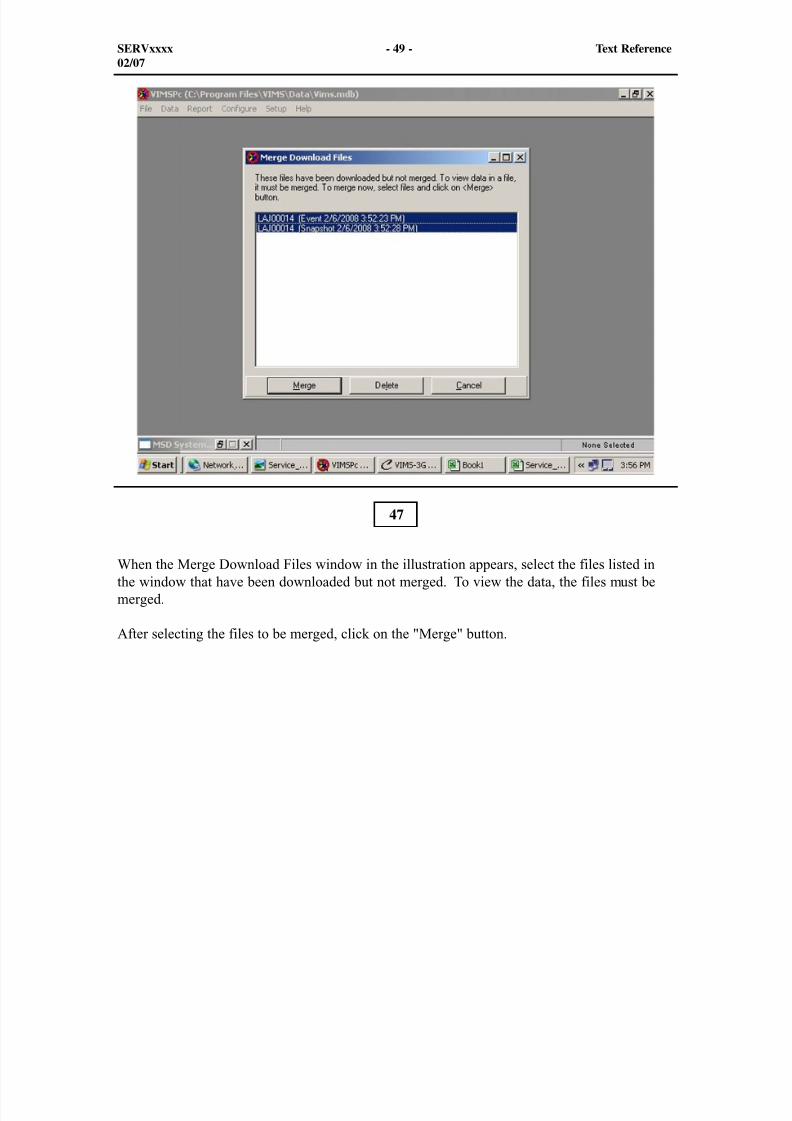
8/9/2019 797F HAA - Meeting Guide.pdf
http://slidepdf.com/reader/full/797f-haa-meeting-guidepdf 365/367
SERVxxxx - 49 - Text Reference02/07
When the Merge Download Files window in the illustration appears, select the files listed inthe window that have been downloaded but not merged. To view the data, the files must bemerged.
After selecting the files to be merged, click on the "Merge" button.
47
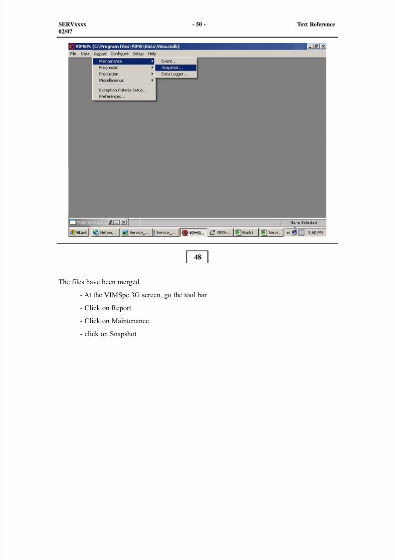
8/9/2019 797F HAA - Meeting Guide.pdf
http://slidepdf.com/reader/full/797f-haa-meeting-guidepdf 366/367
48
SERVxxxx - 50 - Text Reference02/07
The files have been merged.
- At the VIMSpc 3G screen, go the tool bar
- Click on Report
- Click on Maintenance
- click on Snapshot
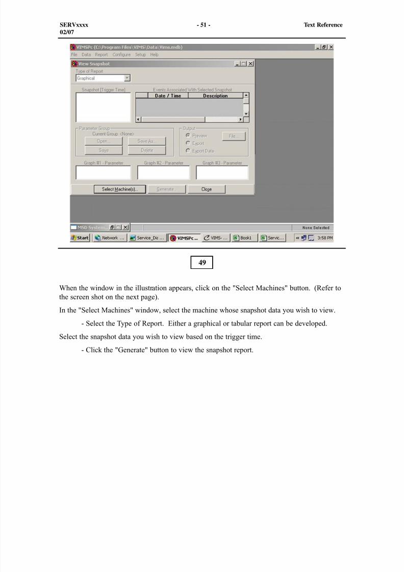
8/9/2019 797F HAA - Meeting Guide.pdf
http://slidepdf.com/reader/full/797f-haa-meeting-guidepdf 367/367
SERVxxxx - 51 - Text Reference02/07
49
When the window in the illustration appears, click on the "Select Machines" button. (Refer tothe screen shot on the next page).
In the "Select Machines" window, select the machine whose snapshot data you wish to view.
- Select the Type of Report. Either a graphical or tabular report can be developed.
Select the snapshot data you wish to view based on the trigger time.
- Click the "Generate" button to view the snapshot report.