7851 Cessna Ave. Gaithersburg, MD 20879 301-977- · PDF fileTECHNICAL INNOVATIONS 7851 Cessna...
49
HD10 observatory in Vermont, photo courtesy of Ray Gadue TECHNICAL INNOVATIONS 7851 Cessna Ave. Gaithersburg, MD 20879 301-977-9000 ©2002, NetLink Technologies, Inc. Chapter 1 Observatory Design Principles Chapter 2 The Fine Print — Definitions & Legal Issues Chapter 3 Constructing a Concrete Pad Chapter 4 Constructing Walls for a Dome Chapter 5 A Dome on a Home (or other building) Chapter 6 Pier Design and Construction Appendix Dome Dimensions Worksheet
Transcript of 7851 Cessna Ave. Gaithersburg, MD 20879 301-977- · PDF fileTECHNICAL INNOVATIONS 7851 Cessna...

HD10 observatory in Vermont, photo courtesy of Ray Gadue TECHNICAL INNOVATIONS
7851 Cessna Ave. Gaithersburg, MD 20879
301-977-9000
©2002, NetLink Technologies, Inc.
Chapter 1 Observatory Design Principles
Chapter 2 The Fine Print — Definitions & Legal Issues
Chapter 3 Constructing a Concrete Pad
Chapter 4 Constructing Walls for a Dome
Chapter 5 A Dome on a Home (or other building)
Chapter 6 Pier Design and Construction
Appendix Dome Dimensions Worksheet

Page 1-1
TECHNICAL INNOVATIONS
7851 Cessna Ave. Gaithersburg, MD 20879 USA
(301) 977-9000
Design Considerations Before we talk in detail about designing your observatory installation, let's review the various types of observatories. This will help you understand the many advantages of the dome observatory, or you may find that an alternative design best meets your needs! Any properly designed observatory will protect your observing equipment from most adverse weather effects (though not necessarily all of them). But there are other design goals as well: • view of the sky in all directions • security of equipment • protection from bugs and animals • power for computers, clockdrives, etc. • adequate storage and "moving-around" space The physical design (including the choice of materials) of the observatory must also take into account • the specific site, size, ground slope, and location • the type of observing you do • available funds • aesthetics • future plans for your property Interestingly, astronomers seem to have invented nearly as many observatory designs as they have telescope types! Nevertheless, as with telescopes, the designs suitable for home and small institutional observatories fall into a few basic categories.

Page 1-2
Observatory Types A temporary observatory is one that is installed only for a short time: one or a few observing sessions. A temporary observatory can provide weather protection for a few hours or days. Special purpose tents, or even just wind baffles, have been used for this purpose. But a temporary observatory can take a substantial time to erect, will generally not provide protection of equipment in severe weather, and may add to the complexity of a set up.
An interesting variation on the temporary observatory is the use of a small permanent observatory on an automobile trailer (e.g., HOME-DOME on a trailer). The structure is permanent, but the location can change, combining the advantages of both the temporary and permanent observatories. Permanent observatories should be designed for long life and for equipment safety in all weather conditions. The remainder of this chapter describes the various types of permanent observatories. We will classify permanent observatory designs according to how the designer has solved the problem of providing visual access to different parts of the sky.
If the observer does not need access to the whole sky, the observatory may be very simple. For example, a conventional building with simple openings (trap doors) in the roof or walls may allow the desired observations near the zenith, or over a selected portion of the ecliptic. However, most observers want to view all parts of the sky at will, so a "hole in a roof" design is very limiting. Since a transparent, optically perfect roof is too expensive for most of us, we need to find ways to look through a more conventional opaque roof structure. There are only two ways to construct a roof that will allow
viewing of the sky in any direction: • remove the all or most of the roof (and possibly the walls) when ready to observe • provide an opening in the roof, and then move the roof (or building) to the direction desired. Removable Roof Observatories The easiest ways to remove the roof are to • flop it down in parts, i.e., roof sections are hinged to hang down over the walls • slide it to one side, i.e., move the whole roof away from the
building The advantage of a flop down design is that there are no sliding parts: all moving parts are on hinges. Thus, the design is relatively simple, and it can be relatively inexpensive to build. However, the disadvantages of the flop-down are also significant: • Roof components are heavy. Opening and closing sections of roof can be very difficult, especially in high
winds or with just one person working. Counterweighting may be necessary, but tricky to do. • It is difficult to design joints that will not leak. • A flop down roof provides relatively little protection for the observer. When the roof is fully open, stray
lights and wind are not blocked.
FIGURE 1.1
FIGURE 1.2

Page 1-3
• It can be difficult to design a flop down that will give full access to the sky (especially in the larger sizes) since the roof flaps must meet and join at the peak of the roof, usually right above your telescope. Unless a structural member (e.g., a beam or rafter) is present, this joint can be a major area of weakness in the roof. The slide-off or roll-off observatory is a different way to remove the roof so you can view the sky. The roll-off observatory is usually rectangular, and the roof is
most often a single gable design, i.e., a simple peaked roof. The tops of two walls have rails or tracks that extend out past one end of the observatory, while the roof has rollers on the underside of its edges. To open the roof, the user unhooks latches that hold the roof against wind, and rolls the roof along the tracks to the side of the building. The advantages of the roll-off are: • Building joints are linear, so that simple rollers and
straight structural components will serve. • The skills involved in building the roll off are
similar to those in common home construction, so many people feel comfortable with it.
The disadvantages include: • The space requirement is twice that of other designs, because you need to store the rolled off roof. • The design must prevent rain from blowing in along the sides as well as at the ends of the closed roof. • The roof must be protected from blowing off in both the closed and open positions. • With the roof open, the observer is exposed to wind and stray light. • The force required to move the roof can be surprisingly high. This depends on the details of design and
construction, the weight of the roof, ground shifts that change the building alignments, and the choice of rollers and rails.
Most designs of flop-downs or roll-offs also involve a trade-off between being able to see down to the horizon vs. protection from wind and stray lights. If the wall is low (allowing you to sight the horizon), then wind and stray lights may be a problem. Portable baffles can help with this in some circumstances, but tend to be awkward, and may take valuable space in the observatory. This problem arises because all or most of the roof is being removed from the observatory, so the shielding effect is lost.
FIGURE 1.3
FIGURE 1.4

Page 1-4
Rotating Roof Observatories If we want to avoid removing the roof from the observatory, we can instead provide one or more openings in the roof, and then turn the remainder of the roof (or supporting building) to aim the aperture at any particular point in the sky. Since most of the building remains covered, the roof continues to block wind or stray lights. As the earth turns, the roof position must be adjusted to allow continued observation of the chosen point in the sky. The roof of such an observatory may be of any shape, but is usually circular to simplify the rotation system. The shutter covering the aperture must be weather-tight when closed, and must cope with wind loading when open. Problems of shutter design are some of the most difficult design issues for the common observatory, and their solutions largely dictate the design of the remainder of the roof. The roof doesn't have to be a hemisphere! For example, a roof may be conical, cylindrical, cubical, or other shape. One of the problems in most such designs is the difficulty in providing a clear shutter opening past the zenith. It is also difficult to make the shutters themselves. For example, many such designs require multiple shutters with overlapping joints or some sort of flexible shutters. In any case, problems can occur with weather tightness, expense, operation in strong wind, and, in some areas, ice. Corners and edges in the roof introduce areas of weakness, potential leaks, and difficulties in construction.
Odd observatory shapes are often appropriate for specialized astronomy, such as solar observing, in which the object ranges over a relatively limited part of the sky. But for the typical amateur who wants to be able to look easily in any direction, a roof without overhead edges or joints is more desirable. While a hemispherical roof is the natural answer, there are still other variations. For example, the shape may be
ellipsoidal, or the dome may be more or less than a hemisphere. And one need not necessarily stick with a horizontally rotating hemisphere: As the Porter turret telescope at Stellafane showed, there are some advantages (and disadvantages) to using a roof rotation axis that is not vertical. The Hemispherical Dome The hemispherical dome does have many advantages over other shapes. Not the least of these is its attractiveness: a well-designed and finished dome reminds us of Mt. Palomar and other great observatories. These aesthetic considerations are important: the owner and the neighbors will be looking at this structure for a long time! A well-designed dome also offers superb wind and stray light protection. And, with a generous shutter opening, a dome gives a wide field of view of the sky. Designing a dome observatory appears easy because it is a simple shape, based on the simplest figure, the circle. But, as is often the case, life is not that easy, so let's look at some of the design challenges for a hemispherical dome.
FIGURE 1.5

Page 1-5
Many people are not aware that a circle is one of the weakest structures: it can take very large forces if they are uniformly applied, but is amazingly easy to distort if non-uniform forces are applied. The "equator" of a hemispherical dome shares this property: if not designed properly, it can deform and become hard to turn when the user applies force to turn the dome. To obtain a properly rigid dome, one must reinforce the equator, and indeed, all the related arcs in the dome. In the HOME-DOME, wide internal flanges on all circular arcs provide this strength.
Shutter Design Another design challenge for astronomy domes is the shutter opening. The most obvious issue is how the shutter will open and close, including the ability to operate it either manually or by an electric motor. A less obvious problem is how to construct the opening itself so that it will have sufficient rigidity: recall that the opening is in a spherical shape without much resistance to deformation. When we try to design a shutter that opens past the zenith, we immediately run into another challenge: where does the opened shutter get stored? After all, if the dome is a hemisphere, a shutter opening that goes past the zenith requires a shutter that is longer than the storage space available on the back side of the dome. Will we just let the shutter hang down the back and perhaps flap in the wind? This design problem has had several different solutions: • Provide one or more shutter sections that can be lifted from the dome and stored elsewhere. This solution will
function for small domes, but in larger domes, the weight of the heavier shutters, and the effect of wind on their larger area, can cause major problems in handling.
• Use a flexible shutter that rolls or folds (in accordion pleats) out of the way. The problems are how to assure
smooth operation under cold and ice conditions, obtaining a long life for the shutter, and providing weather tight operation along the shutter edges.
• Use sideways shutters. This design is used in many large domes. However, it does require coordinated
movement of the top and bottom of the shutters on one or both sides of the opening. A strong frame must be attached to the dome to hold the shutters in both open and closed positions, and must function under all wind conditions. Sideways shutters have long joints susceptible to water leakage.
FIGURE 1.6

Page 1-6
• Use a two piece non-nesting shutter. The shutter is in two pieces, but cannot be stored out of the way. In one design, the upper shutter is moved up and over the dome, and the lower shutter is flopped down (open). In an alternative design, the upper shutter alone is moved up, thus allowing use of the upper part of the shutter opening. If one desires to use the lower part of the shutter opening, the lower shutter is attached to the upper shutter, which can pull it partway up. The major disadvantage is the inability to use the entire shutter opening, thus complicating the sequencing of observations at different altitudes, and reducing the amount of sky that is visible.
• Use a two-piece nesting shutter. Both the front and top piece move together, with automatic disconnecting and
nested storage on the back of the dome. This is the system (patent pending) used in HOME-DOME observatories, and provides for a fully open shutter, convenient storage of the shutters, and low wind resistance in both open and closed positions. And since the shutters straddle the shutter opening flanges, the system is weather tight without gaskets.
These are alternative designs for the mechanical design aspects of the shutter. But in addition to the physical opening and closing, the size of the shutter (i.e., the width of the slot) is of great importance. In general, you will want as wide a slot as feasible. A wider view of the sky allows more enjoyment of the night sky, and easier orientation for the observer. In addition, a wide slot allows you to use the telescope for longer periods, without turning the dome. However, as you might expect, the wider the slot, the tougher the design challenge! No matter how this design problem is solved, a shutter opening represents a cut into the hemisphere. There is no physical "center" at the top of the dome (since the zenith is open), so all forces in the dome have to "go around" the shutter opening. This requires that the opening be strongly framed, so that neither the dome nor shutter opening will distort under load. The HOME-DOME solves this challenge with wide flanges along the shutter opening (used also to guide the shutter and to provide the weather tight operation) and with cross bracing at the top rear of the shutter opening. Designing a Dome that Turns Having designed the shutter and shutter opening, we still must aim the aperture around the sky. The primary design challenge for a rotating roof observatory is to assure easy turning of the dome. As noted above, the equator of the dome is a circle that is relatively easy to deform. In fact, the very forces used to turn the dome deform the dome and introduce resistance to the rotation that can further increase deformation.
FIGURE 1.7

Page 1-7
To illustrate this, imagine yourself inside a small dome to be rotated by hand. As you push tangentially on the inside of the dome, you are also, in part, applying a radial force that tends to shift the dome off center. This causes the portion of the equator behind you to contact the wall (or other surface). As you push the dome, any drag behind you will increase that contact pressure, thus further increasing the drag. And as the drag increases, the dome equator can distort in such a way as to further increase the degree of contact. The result can be a dome that is difficult to turn. The HOME-DOME solves this problem in several ways. A radially rigid equator flange and easy rolling wheels reduce initial drag. When the dome is being pushed at one point on the interior (as is typical), the dome moves off center a maximum of about 1/4 inch and any sliding contact area will be between the
inside of the dome support ring and the outer base ring. Since both of these are smooth, gel coated surfaces, friction is low and the dome remains easy to turn. In larger domes, horizontal wheels may also be used to reduce drag. In observatories using electric drives, except for the smallest HOME-DOMES, two or more motors are symmetrically spaced around the circumference. This minimizes drag by balancing the radial forces acting to move the dome off center. Metal or wood domes are usually very much heavier than the fiberglass HOME-DOME. In these domes, the designer usually installs a track or pair of rails on the underside of the dome equator (and or on the top of the wall) to guide the wheels and reduce drag. Such tracks must be accurately circular and rigid. The tracks increase the overall dome weight, and often impose requirements for rigid and expensive walls. With the shutter and dome rotation design challenges solved, a dome observatory has the advantages of all-sky viewing while providing excellent weather and stray light protection. If provided in modular components, the dome is fast to install, and requires the minimum space --especially important for on-structure installations. The disadvantages of a dome observatory are that its construction does involve use of compound curves, which require precise manufacturing and good quality control. Inadequate designs for the shutter and dome rotation, or
poor material choice for the dome, will produce a dome that is at best awkward to use, and at worst, unusable. At Home in your Dome No matter what type of observatory you construct, you can make it comfortable and efficient to use. If you purchase a manufactured observatory, you will be able to purchase options that fit the observatory to your observing style. For example, you may want to purchase an electrically operated shutter, electrically operated dome rotation, or remote control systems. There are also many "comfort additions" you may want in your observatory including: • A variety of lights, from bright lights for working in the observatory to dim and red lights for night use • Shelves to store books and notes • A cabinet to store eyepieces, photo gear, and other equipment • Carpet to give warmth and comfort to your feet
FIGURE 1.8
FIGURE 1.9

Page 1-8
• A heating pad to put on your lap while observing, or to warm your gloves when you have to work bare-
handed • Power circuits for your computer, lights, etc. • A table for writing notes • An eyepiece holder on your pier for convenient use • A telephone or intercom (though for many of us, a night of observing is a chance to escape these devices!) Summary Here is the bottom line: there are usually several observatory designs that can, in varying degrees, meet your needs as an observer. But for convenience, weather resistance, long life, compactness, ease of use for general purpose astronomy, and elegance of design, a well designed hemispherical dome is hard to beat.
.

Page 2-1
TECHNICAL INNOVATIONS
7851 Cessna Ave. Gaithersburg, MD 20879 USA
(301) 977-9000
Introduction In this chapter, we review the definitions of some of the words we will use throughout this book. For example, what do we mean by "foundation"? In addition, we discuss legal and regulatory issues that may arise in your installation. For example, do you need a building permit? What permit issues arise when you want to put a dome on your house? And just how does the zoning law work? While many of us approach these as issues to be avoided, it is far better to deal with them up front, rather than to run afoul of government regulation later. To that end, this chapter will help you understand the system so that you can more easily achieve the installation right for you. Physical Definitions When we discuss the physical and legal aspects of the installation, we need to be sure of the meanings of certain words. Foundation. The foundation is the structure on which the base ring or wall of the observatory rests. The foundation may be a pad or other structure on the ground, or it may be the structural elements of the upper floor of a house on which the observatory is placed. The foundation provides stability to assure that the observatory remains level or at least, in a plane. If a HOME-DOME is to be used, you will find that it is light in weight. In contrast to the foundation of a house, the HOME-DOME observatory foundation does not have to resist significant weight from above, although it must provide enough strength to hold the structure in place during windstorms. Metal or wood domes, which are much heavier, may require much stronger foundation structures, especially if installed on a building. Floor. The floor is the interior surface of the observatory, where the observer stands and moves around. The floor may or may not be a part of the foundation that supports the observatory wall and dome. But the floor must be reasonably stable, and should be easy to clean and keep dust free. If possible, it should be comfortable for the feet: bare concrete can be very cold and hard. The floor should also be a reasonably permanent material: in tropical areas, untreated wood is a favorite food for bugs. Many people find that a wood floor, or a concrete floor with carpet, is attractive and comfortable.

Page 2-2
Pier. Using an observatory means you no longer need to move the telescope around, or put up with tripod legs that are always in the way. You will want a permanent, stable pier to support the telescope. If possible, the pier should be separated from both the floor and the foundation, so that wind on the dome or walls, or your own movement on the floor, does not cause either vibration or tilting of the telescope. Short rigid piers are preferred, but you should be aware that there is much mythology in pier design. What is needed depends very much on your type of observing. While one astronomer is satisfied with a thirty foot high pipe only 4.5 inches in diameter, another demands a twelve inch pipe set in concrete in bedrock! But whatever your needs, you must plan for the pier when you design the observatory or you may find the need to run a pipe down through your living room! In Chapter 7, we discuss a variety of pier designs suitable for a "Dome on a Home". Legal Definitions and Processes In addition to the "fun" challenges of designing a home observatory, there are the not-so-fun legal issues. These are important: inattention to legal issues can keep you from completing your project!
Legal issues arise from the requirements of local zoning law, requirements for building permits, and in many areas, community covenants. Let's try a few more definitions. Zoning Laws. The local town, city, or county usually imposes zoning laws. A zoning law establishes or defines different zones, each with a list of permitted uses. That is, the owner of property covered by that zone has the right to any of the permitted uses for that zone, within certain predetermined restrictions. Generally, uses not listed as permitted in a zone are forbidden. A typical zone might allow use for single family residential dwelling up to some particular size, with some minimum amount of land. If you meet these minimum restrictions, you can build any type of house you want as far as the zoning law is concerned. The zoning law usually also provides for special exception uses, i.e., uses that are granted subject to special conditions tailored
to the specific situation on a particular parcel of land. Once the laws establishing the zoning categories and uses are written, the parcels of land in the jurisdiction are assigned to zoning categories. Once imposed, the zone applied to a particular piece of land can be changed by application of the owner, or by legal action of the government. Some areas, especially very rural areas, are not covered by zoning laws. Accessory Building. In zoning law, a lot (parcel of land) will usually have a primary use that is associated with some particular structure. For example, a lot in a single-family zone will have a single-family house as the primary structure accommodating the primary use. The lot can usually also contain one or more accessory uses or buildings. Garages, garden sheds, and observatories are all accessory buildings. If you are in a single-family residential neighborhood, your lot is probably in a residential zone. Such zones almost always allow accessory buildings. The law (and supporting regulations) usually also place restrictions on the accessory buildings. For example, they may limit the size and height of structures, and may require accessory buildings to be placed in the side or back yard (i.e., not the front yard), with specified minimum distances to the lot line. In many jurisdictions, an accessory building less than a certain minimum size is specifically exempted from needing a building permit (see below). The minimum size is usually about 100 sq. feet, so a HOME-DOME up to ten-foot diameter is then exempted.
FIGURE 2.1

Page 2-3
Building Permits. Another set of local laws may require building permits. With certain exceptions, if you wish to build or modify any structure, you will apply for building permit (the term also includes electrical, plumbing, excavation, and other permits, as well). Your permit application includes drawings of your proposed work. When the government reviews the permit application, the staff look at the design and construction details to see whether they meet the building code requirements. They also look at the intended use of the building, and check it against the zoning law and the zone that is assigned to your lot. If there is a problem in any of these areas, you either make changes in your application, apply for a special exception or variance, or the government refuses to issue the permit. Zoning laws are usually enforced by the granting or withholding of building permits. With reference to observatories, the easiest building permit to get (if one is needed), is one to construct an observatory as an
accessory building on, say, a concrete pad. In contrast, constructing an observatory on an existing building can be more complex since you will likely be modifying the building. In this case, your permit application would need to show some of the existing building structure, and how your dome will be fastened to it. For an on-structure observatory (i.e., on a house or accessory building), one vital, but subtle, issue may be whether your observatory is ON the roof, or IN the roof:
• "ON the roof" means that the observatory, and its floor, rest on supports over the existing roof with minimal penetrations through the roof. • "IN the roof" means you have cut into the roof surface, and that the dome now serves as the roof. IN-the-roof installations raise structural issues, but also issues concerning roof material because you are now substituting the dome for what was part of the roof (as one would do when installing a skylight). With your dome now a part of the roof, it
must meet the same structural and fire requirements as the original roof. For example, a fiberglass dome may require special fire resistant resins to match the fire resistance of the original shingles. Thus, the "detail" of ON vs. IN the roof may trigger very different permit requirements. That is why it is best to resolve these issues before construction, and even before ordering your dome! If you need to apply for a building permit, the building permit folks, as well as common sense, will require that you prepare reasonably complete and accurate plans for the project. If you do not have structural plans for your building (and few of us do!), a combination of pictures and sketches showing the present construction will be needed. In general, permit authorities do not require fancy blueprints, but they will require accurate fully dimensioned drawings or sketches. The drawings must include all structural members, how the new work will be tied into the building, and details on how the dome will be supported. The staff may ask questions about the weight, thickness of fiberglass, and other characteristics of the dome itself. The specifications for the HOME-DOME, and the installation details in the instruction book, should go a long way to answer such questions. You will normally be charged a building permit fee, usually less than $50. And the building permit enforcement staff will likely visit your job site at least once, to check that the construction is done according to plan
FIGURE 2.2
FIGURE 2.3

Page 2-4
(and that the plan accurately reflects the actual situation). It is possible at some point that the enforcement staff will recommend or require a change in your plans. If you believe the change is reasonable, there is no problem. But if you do disagree with a requirement, you can usually negotiate some way to settle the issue. If an impasse occurs, you should be aware that there is usually an appeal process. What happens if you are required to get a permit, but do not do so? If you go ahead with a project that is legal except that you did not get a permit, you may have to pay a fine, and still have to go through the permit process. However, if your unpermitted project has some defect with respect to the law, you may have to rip out or modify part of your installation, or even remove it altogether. It is best to check first, and to comply with the law! Insuring your observatory is an additional consideration. Your observatory may be covered under your current homeowner policy; however, you should check with your insurance company to be sure. In any case, if you have not obtained proper permits, and some damage to the dome or house occurs, your insurance company may refuse to pay. Easement. An easement is permission to use part of your property that you or a previous owner granted to another party by deed. For example, there are usually easements for underground utilities that allow access by the utility company, and which limit your ability to construct a building over (on) the easement. Your property may have easements on it that affect where you could construct an observatory. You may have an underground septic tank and drainage field area, or even an underground power line, over which buildings cannot be placed. To find out what easements may be on your property, check the deed and plat which list the easements. You can also check with the zoning authority or utility companies, which often maintain maps showing the easements. Violations of easements are enforced by the building permit process, or by legal action of the easement holder. Covenant. Covenants are restrictions of property use that appear in the deed. For example, covenants might place some special limit on the type or size of an accessory building, or even on the use of outdoor lighting! In our context, however, the most relevant covenant is one that requires you to follow regulations established by a condominium or homeowners' association. These may set limits not only on the size and scale of structures, but also on style and color that you can use on your house. Accessory buildings may be very severely restricted. Government rarely imposes these types of controls. Covenants are restrictions over and above those imposed by zoning law. In some locales they are tied into the governmental building permit process, but in most areas the private association enforces them. The association may require its own building permit or certificate, the purpose of which is to determine whether your plans conform to the covenants and regulations. Enforcement is usually by moral suasion, imposition of fines, or by civil action in court. Some associations are liberal in their enforcement of covenants and are flexible in allowing for special projects, such as observatories. Others, however, are very inflexible, and maintain very strict control over what can be done. In either case, it is best to try to work within the system. Try to enlist the support of your neighbors before you apply for permits. Strengthen your case with a showing of your community spirit: community use of the observatory (an example is to work with scouts for merit badges) may help win approval of your observatory plan. Show sensitivity for community values by designing an observatory that fits into the neighborhood, by use of screenings, plantings, and choice of dome and wall color. You can also sign an agreement to remove the observatory when you sell the property. Finally, the whole issue of covenants applies to on-structure domes just as it does to stand-alone domes. If your property is covered by covenants, you should check ahead of time as to what is permitted, or ask for special permission as may be required.

Page 2-5
Summary An observatory project must satisfy the local legal requirements in your area. Because the issues are different in every locale, you need to understand what applies to your situation. In some areas, there are few restrictions, and virtually no approvals are necessary. At the other extreme, you may find many apparent roadblocks in the way. In this case, it is best to keep an open mind and a sense of humor! You might want to talk to others, such as architects or contractors, who have done successful projects in the area. You may want to seek compromises or project changes that will meet the objections of others, while still achieving your own goals.

Page 3-1
TECHNICAL INNOVATIONS
7851 Cessna Ave. Gaithersburg, MD 20879 USA
(301) 977-9000
Introduction In this chapter, we will discuss one of the most common installations - constructing an observatory on a concrete pad. Many people are unfamiliar with handling and finishing concrete, but could do so with a few hints. Therefore, we have included substantial detail on the actual construction of the pad, including the "magic" techniques used in finishing the concrete to produce a flat surface. A concrete pad will usually include pipes for power and signal cables, and an opening for the pier of choice. The minimum size of the pad is that needed to support the observatory. The pad may be circular if HOME-DOME walls are used, or rectangular if you are building your own observatory walls. However, there are often good reasons to construct a larger pad than the minimum. You may want to allow for a larger
observatory in the future, or you may just want space for lawn chairs. Or the observatory project may be an excuse to build a patio useful for other family activities. Also consider non-circular or rectangular pads. Kidney shaped pads lend themselves to attractive plantings, so you may want to incorporate some raised beds for flowers. Your observatory can be as beautiful to look at in the daytime, as the skies are at night!
Pier in a Pad In Figure 3.1, we show a pad with a hole left in the middle for a pier or post to hold the telescope. However, there are good reasons to construct a pier for your telescope before you pour your pad. You may want to look ahead to Chapter 7, which discusses pier design. Figure 3.2 shows a pad and pier cross-section. A typical design for a pier would use a 4 to 12 inch diameter pipe embedded in a concrete footing of 3-4 feet
FIGURE 3.1

Page 3-2
in diameter and 3-4 feet deep. You would not want this big a hole in your pad, since it will create an uneven floor near the pier. Therefore, you would likely want to pour the footing before you pour the pad, so that the pad can extend over the footing (but not touching the pier). But if you do that, how can you change the pier height later if you get a different telescope? One way to keep your options open, and to pour both the footing and the pad at one time is to proceed as follows: •Excavate the pier footing as desired. You do not normally need to put smooth forms on the inside of the hole. •Install a length of pipe of larger diameter than your intended pier, and extending a few inches above your planned pad. Brace the pipe in the hole so that it is reasonably vertical. •Complete the form for the pad, as described below. •Pour the footing around the pipe. •Cover the footing (while it is wet) with previously prepared cushioning material.
•Pour and finish the pad as described below (avoid walking over the footing). After the pad and footing are cured, you can insert a pier pipe of the desired diameter and height, and fill the annular ring around it with concrete. Because only a small amount is needed, this will be easy to prepare using pre-bagged "sand mix" (cement plus sand as the aggregate). You might even consider tamping in sand instead of concrete, so that you can easily remove it later. Cost of a Concrete Pad Advantages of a concrete pad are that it is permanent, stable, can be made moisture tight. A pad can be built by a do-it-yourself person (even with no experience), and is relatively cheap. A pad is also quick to produce, in contrast to constructing a building. For example, one might typically spend a day preparing the pad area (leveling the area and laying down a few inches of stone) and building a simple form.
For a ten-foot diameter pad with a four-inch thickness, about one cubic yard of concrete is needed. This is more than you can mix by hand, and more than most people with a small mixer want to do. But this is a small load for a concrete truck, which in many areas will deliver a cubic yard for about $200. After about four hours of work in spreading and finishing the concrete (and a few days for curing of the concrete), you will have a beautiful pad ready for your dome. As you design your pad, consider what shape and size you want. As we noted above, you may want to incorporate an entrance step or stoop in the pad, and you may want to make the pad large enough to serve as a patio or picnic table area. Consider incorporating planters, or raised beds for flowers, so that your overall installation will be beautiful even for non-astronomers. Be sure to construct a pad at least a little larger than the minimum needed. For example, a ten-foot HOME-DOME has an outer wall diameter of 119 inches. However, if you try to make the pad exactly 119 inches, errors in measurement, or movement of the form, may result in some areas where the wall will not be fully supported by the pad. Even more troublesome, you will find that the few inches of the pad closest to the edge are the most difficult to level accurately. Bumps or slopes in this area may then make installation more
FIGURE 3.2

Page 3-3
difficult. Finally, a pad larger than the observatory wall prevents lawnmowers and other machines from striking and damaging the wall. Overall, the small amount of extra material needed is well worth the cost. Preparing the Form There are several methods of preparing the form for the pad and then smoothing (finishing) the concrete. The easiest, of course, is to get a friend who has done concrete work to do the job. But that avenue means YOU won't get the pleasure of learning this mystical craft! One method that might occur to you is to build the form to exactly the "correct" height so that the concrete will fill it precisely to the brim. If the top edges of the form are precisely uniform and level, one could then run a long board (a "screed") across the pad to level the concrete and finish it smooth. However, most of us find such a "simple" solution to be unworkable in practice for a variety of reasons: •Making the form edges precisely level and uniform is very difficult, especially if scrap lumber is used. •Stakes cannot project above the form edge. •The aggregate (rock) in the concrete makes using a screed to move the wet concrete very difficult. •The amount of concrete and the volume of the form may not be an exact match. •The quality of the surface finish one can obtain is relatively poor. Using the methods described below you can actually construct a pad when working alone, and without special tools. Of course, pad building is easier and more fun with another person helping.
It is easiest to make the form of wood. The only real trick is to realize that the concrete is quite heavy. Even for a typical thickness of only four inches, wet concrete will push outward on the form with many tens of pounds of force. So you must brace strongly the outside of the form. If you make a curved or circular form, install stakes about every foot or so, and brace the stakes if necessary. For the form material itself, use one or more thicknesses of thin plywood, Masonite, or other veneer material to
make the curves. For a square or rectangular form, use pieces of wood planking, braced with stakes at the ends and along the middle. As you construct the form, be sure the dirt under the pad is well compacted and level. If the soil is loose, it will settle and could lead to cracks in the pad, or even creation of a tilted pad. You can compact the dirt by running vehicles over it, tamping it by hand (the harder the better), or renting a tamping machine. You also need to assure that the dirt is reasonably level (+/- 0.5 inch). The easiest way to do this is with a water level, available at larger hardware stores for about $10. The water level can be used for other parts of the project, as well. After preparing the dirt and the form, place about two inches of crushed stone over the dirt to promote drainage under the pad. Then install a layer of plastic (ordinary polyethylene will do) on the stone. This will help keep water in the ground from dampening the concrete pad. Finally, lay reinforcing wire on the plastic. The purpose of the wire is to ensure that any small cracks that might occur remain small in size. That is, the wire will help hold the pad together and level, even if it should crack due to uneven settling of the soil, for example. You can buy reinforcing wire, or you can use old fencing, bedsprings, or other material. It does not all have to be one piece or wired together - what counts is that the pieces of wire overlap so that the concrete will bond it together.
BRACING THE FORM
FIGURE 3.3

Page 3-4
Now is the time to install conduit or piping (plastic is easiest) so that you can route cables under the pad to the inside wall of the dome, and to the central pier. Plug the ends of the piping so concrete doesn't get inside. If you want to have a knockout hole in the pad, you can place a can or bucket upside down, with the "bottom" of the container 1/4 inch below the elevation of the finished floor. This will give you a smooth floor, yet will allow easy access to the hole below (if you remember where it is!). Finally, mark the inside of the form to show the expected finish height of the concrete (e.g., four inches above the stone). Use a dark line, because it will become splattered with concrete. You may want to put a second line one inch above the expected finish line in case there is more concrete than you expected. You may also want to put wooden pegs into the dirt floor of the form. These will penetrate the plastic. The top of each peg should be at the same height as the finish height marks on the form. When finishing the concrete surface later, you can remove the pegs or just hammer them below the concrete surface (entombed forever). Use your water level to establish the proper elevations for the perimeter lines and stakes. Final Preparations Now you are almost ready for the concrete (and be sure you are ready - most concrete trucks add additional charges if they have to wait while you finish preparation!). What is left to do? You need tools, and you need clothing. Some of the essentials are shown in Figure 3.4 below.
The tools are simple. You will need a steel rake or hoe for leveling and moving concrete, and a wide, rectangular cement trowel to finish the concrete. You should also prepare the wood tools shown in the figure. And you need at least three boards or pieces of 3/4 inch plywood at least 18 in. square to kneel on, and to use in the concrete finishing process described below. The clothing is also simple. Concrete is caustic: wear gloves. Plan to wear glasses or safety glasses: Concrete droplets in the eye are very unpleasant. You will need to walk in the concrete
for all but the smallest pads, so you will need to protect your feet. You can use boots, or you can put your feet in a couple of plastic bags, and wear an old pair of tennis shoes, which later become a permanent souvenir of your project. An important concern is whether the concrete truck can deliver the concrete directly to the pad. Is there a driveway that reaches your pad? If not, can you accept the damage that a truck will do to your lawn or bushes? The trucks are very big, and very heavy. The truck will have a chute that is about ten feet long, which can be swung to about 45 degrees on each side. If you need an additional 5-8 feet of chute, you can make a wooden chute extension ahead of time. But if you must use wheelbarrows to move the concrete, be sure to have a group of people and barrows ready since this will be a time consuming and tiring process. If you take too long for your delivery, there is an additional charge. Even worse, the concrete will begin to set, making the finish work very difficult. So now you are ready. Order the concrete several days before you plan to pour the pad. Get the type of concrete used for garage floors in your area. It will contain cement, sand, and aggregate (rocks up to about 1 1/2 inch in size). Most concrete haulers require that you pay in advance, or in cash, when the concrete is delivered. If you want to use a check, be sure the driver will accept it. Be sure and ask how much delivery time is included in the charge, and how expensive additional time is. The Concrete Arrives
CONCRETE TOOLS
FIGURE 3.4

Page 3-5
Now comes the truck - twice as big as you expected! When you have directed the truck to the pouring point, have the driver run a small amount of concrete onto the pad (about one wheelbarrow's worth). The concrete should be relatively soupy: you can ask the driver to change the viscosity. If too soupy, it will take forever to cure, but if too thick, will be hard to handle. Using a shovel, put dollops of concrete every few feet on the reinforcing wire. Use the hoe or rake to lift the wire onto the top of the dollops. After the remainder of the concrete is poured, this will assure that a major part of the wire will be in the concrete, rather than under it. After you have the wire on the dollops, have the truck driver run the concrete into the form, while you spread it around by moving the chute. Don't hesitate to ask the driver to pour the concrete in bursts, so that you can gain familiarity with it. Some drivers are willing to give you some tips as you work, but don't expect the driver to help in the actual work. Take your time as you work: most deliveries allow an hour or even more for the delivery activity. But also don't waste time: the concrete is setting up with every minute. Once the concrete is in the form, the truck goes away, and you are left with several tons of very lumpy stuff getting hard! But don't panic: you have plenty of time. Leveling and finishing The concrete will be uneven in thickness, and will show large rock (aggregate) on its surface. The next task is to level it. DO NOT move concrete around the pad by using the hoe or rake with the points aimed down, as you normally would. If you do, when you pull the rake or hoe toward you, you will inevitably hook the reinforcing wire and pull it up to the surface. Once on the surface, the wire it is VERY hard get back under the surface. Instead, use the back of the hoe or rake to push the concrete, and lift the rake or hoe out of the concrete when pulling it back to you. In a few minutes of work, you will have the concrete approximately leveled, using the perimeter marks around the form, your height stakes (if any), and your eye as guides. This method of rough leveling is much easier than trying to drag a board across the often uneven top edge of the form. The next task is to get the aggregate down below the surface so that the finished concrete surface will be formed of the finer sand/cement mixture. This is actually fun to do! Using Figure 3.4 as a guide, you will have prepared a 2x6 pusher (sometimes called a "rule") about thirty inches long, preferably with two
handles screwed onto it. As shown in Figure 3.5, stand in the concrete (in your boots), and place the long edge of the pusher into the mushy concrete surface. Push it down, then lift it up about two inches, working your way backwards across the pad at about two inches per cycle (like a washboard). Work from the center towards the perimeter, and your footprints will be filled as you go. This activity moves the large aggregate downward, and
brings the cement and sand up towards the surface. After you go over the pad twice doing this, you will see that virtually all traces of the big rock are gone! This will take about ten minutes. Because of the stooping over, it's a little hard on your back, but not a tough job. You can skip the next step if you want, but the overall job will go easier and faster if you do it. Using your large "trowel" made from 2x4s (called a Darby in the trade), stand on the outside of the form, and sweep the "trowel" in wide arcs across the pad. The lower surface of the "trowel" will be almost flat on the concrete, but angled just enough to smooth the concrete. You will want to go over the pad a half dozen times from all positions. The goal is to smooth the surface, and to redistribute the concrete into a more planar
PUSHING DOWN AGGREGATE
FIGURE 3.5

Page 3-6
surface. In this, as in the finishing steps described below, the object is to make numerous small modifications to the surface that tend toward the desired surface, rather than try to make a correct surface immediately. You will now begin a cycle of working the concrete, and then letting it partially set (cure) before working it again. You will know it is time to rework the surface when it becomes distinctly harder as compared to the last working. During each cycle, you will spend about fifteen minutes working the concrete, then wait 30-60 minutes for additional curing to take place.
When the concrete is ready for another round of finishing, if it is still soft, you can use the Darby. But if it is about strong enough to support your weight on a board without denting more than 1/2 inch, you are ready to trowel the concrete. Place three pieces of board or plywood on the pad. Kneel on one of them; use the second as a place to lean on. As you finish working the
concrete within easy arm's reach, move from place to place on the pad using the third piece to hold you while moving one of the others. You may need extra pieces under your feet so your toes don't dig into the concrete. The first time or two you do this, the boards will make dents in the concrete that you will have to smooth out. After putting the boards on the pad, kneel down, and sweep the steel trowel in wide arcs to smooth the concrete. You will quickly see that some areas are higher or lower than others. Angle the trowel so that you use the flat of the trowel and its trailing edge to sweep the concrete level. Don't try to move the concrete by scraping; instead, move it by continued smoothing actions. As the concrete becomes level, you can use a hammer to knock your wooden height guide sticks down below the surface. Moving over the pad from different positions, you will end up averaging the sweeps so that the pad will become increasingly planar. This is a good time to carry out that most important of activities: carve your initials and the date (and maybe your child's footprint) into the pad! After two cycles around the pad from different directions, get off the pad, and let it cure for another 45 minutes or so, then do it again. After several complete cycles of troweling, you will find the concrete increasingly stiff, and you will put relatively more effort into smoothing and hardening the surface for a fine finish as the leveling takes care of itself. Neat! After three or four complete cycles of smoothing the concrete, it will have set hard enough that you can do little more. After another 6-12 hours, you should remove the form. You will find that the concrete has a ridge where it joined the form. If left in place, the ridge will prevent water from draining off the pad. With the form removed, but with the concrete still relatively soft, use a trowel edge, or cold chisel, and bevel the edge of the concrete. After finishing your work on the pad, cover the concrete with plastic sheet, so that the surface does not dry out. Concrete hardens by the cement chemically combining with the water, not by "drying out". If you do not cover the concrete, the surface drying will deny water needed to combine with the cement. The result can be a surface that releases excessive concrete dust. After about two days, the pad will be sufficiently cured to walk on or to drill holes and install anchors for the observatory base ring. Be careful when working on it for the first week or so because concrete does not fully harden for several weeks.
FINISHING CONCRETE
FIGURE 3.6

Page 3-7
Non-Pad Foundations While this chapter deals primarily with constructing a concrete pad, there are other types of foundations that can be used. Two common types are a ring foundation and pilings.
A ring foundation is a "wall" in the ground to support the observatory. The foundation will usually rest on a footing of concrete poured on the bottom of the trench. The footing spreads the weight, and provides a reasonably level base for the foundation. The foundation itself may be constructed of poured concrete or of concrete block. If poured concrete, the ring is usually about 5 inches thick and 24-36 inches deep. If constructed from concrete block, the ring will be about 8 inches thick. In any case, leave holes for wires to pass through the foundation.
An entrance stoop or stairs may or may not be constructed as part of the foundation. A big advantage of a ring foundation made of concrete block is that it can be constructed in stages, by hand, without pouring large amounts of concrete. The observatory floor may be made of concrete poured at a later time, or may be made of wood supported above the ground. If the observatory walls are to be masonry, they will likely require a ring foundation. Pilings are supporting posts spaced around the perimeter of the walls. A ten-foot diameter dome might have eight or more pilings. A piling might be a treated wood post sunk into the ground, or it might be constructed of block or poured concrete. Usually a sill of some sort is constructed that connects the tops of the pilings. For example, eight wood pilings might have 2x8s bolted to the pilings to form a continuous octagonal support for the base of the observatory. A wood floor can easily be built onto such a sill. The advantage of pilings is that the whole foundation can be done with no concrete at all - an important advantage for a remote observatory. Also, there is much less excavation for pilings than for a ring foundation. Finally, pilings are probably the least costly foundation. Attaching the Observatory to the Pad So far, we have described how the foundation is built, but we have not talked about attaching the observatory to the foundation. After all this work, we don't want the observatory to blow away! The details of attachment, such as the number of bolts, use of washers, etc., depend on the details of the observatory design. However, there are several typical methods used to provide anchor bolts into concrete, and each has advantages and disadvantages. One method of providing bolt attachments to a concrete pad is to cast threaded rod into the concrete. This sounds easy, but is not so easy in practice. •Each bolt location must be accurately surveyed: changes after the fact are difficult. •Each bolt must be held in a rigid, vertical position, even when concrete is pushed up against it. •Threads must be protected from the concrete. •Transferring the bolt locations to the mounting ring of the observatory is difficult, especially if the bolts are not vertical and of uniform height.
ALTERNATIVE FOUNDATIONS
FIGURE 3.7

Page 3-8
While these problems occur, a major advantage is that you will not have to drill holes in concrete at a later time. This is a big advantage for remote locations, where power may not be available. A second anchoring method is to cast female threaded anchors into the concrete. These anchors are available at building supply stores, and some can even be inserted into wet concrete. However, there are still the problems of locating exactly where you want them, and of wasting the effort if you later change your mind on bolt locations. An advantage is that if you do change your mind, you don't have protruding, cast-in bolts that are difficult to remove. A third anchoring method is to wait for the concrete to cure, then drill holes in the concrete where you want the foundation bolts. You can drill these holes quite easily with a 1/2-inch power drill with a masonry bit, which you can rent, if needed. After the hole is drilled, you insert an anchor. When drilling holes in concrete, you will find that the aggregate in the concrete moves the bit off your intended location. You can minimize this by drilling a "small" pilot hole of perhaps 5/16 or 3/8 inch, then redrilling it to the final size. Again, different types of anchors are available for insertion into the hole. Some types of anchors are grouted or epoxied in place. These are easy to use; however, the bond may not be good if the concrete is damp or the temperatures are low. In contrast to these, other types are designed to expand when the bolt is inserted and tightened, thus gripping the inside of the hole. Some anchors accept machine bolts, while others take lag bolts (large, coarsely threaded bolts). Look over the selection at a large hardware or industrial supply store, and select the anchor and bolt system that fits your needs. You will probably want to use at least 3/8-inch diameter bolts with large washers. Anchors for 3/8 bolts usually require holes of 5/8 or 3/4-inch diameter. The anchors should be at least 1 1/2 inches long, and the holes should be at least 3 inches deep so that there is plenty of room for the anchor bolt. This issue of bolt locations is most important for observatories that have pre-drilled foundation bolt holes requiring precise anchor bolt locations. However, the HOME-DOME base ring is designed so that the installer can choose where to put the foundation holes. Thus, we recommend that the desired foundation bolt locations be marked on the pad, then drilled, and anchors installed. If several triangulation lines are drawn to each anchor, when the base ring is placed on the pad over the anchors, the actual anchor locations will be easy to transfer to the base ring. Then holes can be drilled in the base ring that accurately fit the foundation anchors. Observatory Installation If constructed with a reasonable care, your pad should be flat and level to better than 1/4 inch as shown by measurements with your water level or other survey device. When you install your observatory, it is often best to insert shims at the bolt locations to correct for variations in the pad. You can make the shims from 1/8-inch plastic or other material. If you cut a 1/2-inch wide slot in the shim, you can then slide one or more shims under the foundation anchor bolts to level the base ring. When you are satisfied with the installation, tighten the bolts, holding the shims in place.

Page 3-9
You then have a gap that might range from 1/8 to 1/2 inch under the base ring. The easiest way to handle this is to inject expanding foam under the base ring to achieve a watertight seal to the foundation. The foam will ooze out from under the base ring flange, but it is easy to trim with a razor knife after it hardens. The job will look especially finished if you paint the foam with exterior latex paint that matches your observatory color. Summary Constructing and finishing a concrete pad is an amazingly satisfying
job. If you are reasonably patient and consistent in your work, you will find that the surface is well finished (though it will likely have some trowel marks) and it will probably be planar to better than 1/4 in. Pretty good for an amateur!
ANCHORING BASE RING TO PAD
FIGURE 3.8

Page 4-1
TECHNICAL INNOVATIONS
7851 Cessna Ave. Gaithersburg, MD 20879 USA
(301) 977-9000
Introduction This chapter discusses how to design an observatory using walls that you construct. The next chapter discusses how to put a dome on a ready-made building (garden shed, garage, or a house). HOME-DOMEs may be installed on walls assembled from matching rings placed on a foundation. However, many users choose to install their dome on some other type of small building that they build for themselves. This may be as simple as a four sided, four foot high "box" constructed of home made walls, with a "duck under" door entrance, i.e., a door less than a person's height. Such a structure would often be built on a concrete pad, constructed as described in Chapter 3. The walls which support an observatory must provide a circular, flat, level surface for mounting the base ring. The wall must be strong enough to resist wind forces, and should be mounted on a foundation that resists
other weather forces such as frost. Observatory Shape and Size The wall of the observatory may be circular, octagonal, square, rectangular, or any other shape that you wish to fabricate. It may match the dome size or be somewhat larger. Special circumstances may require a building smaller than the dome. For ease of construction, most people construct square buildings. A square or rectangular shape also provides for substantial additional space within the observatory, an important benefit when using the smaller dome sizes. For example, a six-foot dome placed on a square building six or seven feet square gives a surprising amount of useful space.
How high to make the walls depends on your application. Assuming you want to be able to look down close to the horizon, the height of the wall plus base ring should be just below the telescope axis when it is swung
FIGURE 4.1

Page 4-2
down horizontal. A three or four foot high wall is about right for a typical Schmidt-Cassegrain or a 6-8 inch Newtonian on a German equatorial mount. Obviously, if you do not want to look down to the horizon, a taller wall (compared to the pier height) may be desirable. A fork mounted Newtonian or Dobsonian usually requires shorter walls (or a raised pier). A refractor is usually placed on a relatively high pier, thus requiring relatively high walls. The height of the walls also depends on your own height, the size of the observatory, and the likelihood of visitors. A taller wall gives more inside space, but usually requires a taller pier, and possible use of an observing ladder or a raised floor. If the observatory roof is higher than 7-8 feet above the floor, you may have difficulty opening the shutters without ladders or electrical assistance. The height of the walls also affects the design of the entry door. If the wall is relatively low (under four feet) you can install one or two steps and enter the observatory by stepping over the wall through the slot or roof opening. If entry is to be through a door in the wall, a taller wall allows a taller door, and less stooping over to enter the observatory (and easier equipment movement). As noted in the Appendix, the HOME-DOME wall design using wall rings allows you to install a full height door even in a low wall, by using the slot opening for
the upper portion of the door, and a swing-out portion of the wall for the lower door. Finally, if you are building your own walls, consider including one or more windows. They make working in your observatory a pleasure in the daytime! Wall Construction Techniques A wall may be built of bricks or block, but many people find such a wall expensive and hard to build. In addition, a masonry wall tends to retain the daytime heat, and may affect observing quality into the evening. A simpler, more typical, wall is built with 2x4s and outdoor plywood usually covered with vinyl or aluminum siding. You can use horizontal 2x4s (sills) on the foundation, vertical 2x4s (studs) on 16-inch centers to provide the height and hold the siding, and horizontal 2x4s (headers) to form the top. You may want to use pressure treated 2x4s for the sills. When constructing the frame, be sure to measure and cut accurately, so that the walls are square and vertical. Use temporary triangular braces to make assembly easier. You may even want to prefabricate the walls and door in your shop, then erect them on site. Bolt the sills to the foundation using lag bolts or other anchors. The exterior walls can be covered with outdoor plywood or siding. If you want to keep interior temperatures low, you should use a
bright white exterior surface, as is provided on the HOME-DOME. You can use nails or construction glue to fasten the siding, or dry wall screws with an electric screwdriver. The door can be constructed on site, or custom made. Sometimes you can buy a full size door, cut off part of it, and use the remainder for the low door. You will probably want to install some type of finished surface on the inside of your building. Interior plywood or paneling is suitable, as is drywall, which is non-flammable, and a better insulator. A reasonably dark paint inside will help keep your eyes dark-adapted. Be sure to install power outlets, phone wires, and other in-wall services and insulation before you install your interior wall surface! Transition from Square to Circular
FIGURE 4.2

Page 4-3
After you choose the construction technique and establish the dimensions of the wall, the only other major issue is how to make the transition from the flat top edge of your wall structure (usually square or rectangular) to the circular base ring of the dome. The transition is very important: it serves both to keep out the weather and to support the base ring and dome. If you are using a manufactured observatory, the supplier should be able to provide a suitable transition. For the HOME-DOME, Technical Innovations can provide a fiberglass transition, called the "rectangular skirt", that makes the transition from the circular base ring downward four inches to a square that is eight inches longer on each side than the diameter of the dome. For example, the rectangular skirt for the six-foot dome will match the dome to a square wall of 6'8" outside dimension. The rectangular skirt will overhang the wall, providing a watertight joint.
If properly anchored at its edges, the rectangular skirt can also provide all the needed support for the dome, without complex carpentry and flashing under the dome itself (and the space below the base ring will be clear, i.e., without structural material to get in the way). If the dome is to be placed on a wall larger than 6'8", this can also be accommodated so long as a sloping roof is provided to within the 6'8" square so the skirt can be attached. A rectangular skirt is also available for the ten-foot dome. This skirt is also designed to fit to a square eight inches larger than the dome. However, due to the greater weight of the ten foot dome, bracing is required under the skirt to support the dome. On the other hand, many persons want to provide their own custom roof transition design. This is relatively easy to do, but does
require attention to detail to provide structural stability and long term weather tight operation. The simplest transition is a flat, square surface with a hole cut in it that matches the INNER diameter of the base ring. The transition may be constructed from 3/4-inch plywood sections, with suitable bracing on the underside, usually by 2x4s or 2x6s across the corners to form an octagonal support. The biggest issue with the flat transition is how to handle rainfall, snow, and ice so that leakage and deterioration do not occur. You must prevent water from leaking under the base ring, and you also need a good drip line to keep water off the walls. Since it is always possible for some leakage to occur, both plywood and structural members should be protected from rot. If you rely on caulk for the joints and paint to waterproof the flat horizontal surfaces, you will have to pay close attention to maintenance or the system will fail by leakage and rot. In the long run, it is better to design a transition with sloping surfaces, and to cover the plywood with a material that is inherently waterproof. One way to solve this problem is to install sheet metal over the entire transition surface, including under the dome base ring as shown in Figure 4.4. On the inside of the base ring, the metal can even curve up over the lower flange of the base ring. Along the outer edge of the transition, the flashing can hang over the edge of the wall to provide a proper drip line. Pieces of flashing can be joined by soldering (if copper), or by roofing pitch or tar. This solution works well on either a flat or sloping transition.
FIGURE 4.3

Page 4-4
USE OF FLASHING ON FLAT TRANSITION
FIGURE 4.4 An alternative to sheet metal is fiberglass. You can apply fiberglass to the entire horizontal surface of the plywood, carrying the fiberglass under the base ring, and out to and around the edge of the wall. Such a fiberglass job is easy to do on surfaces that are simple, horizontal, and easy to get at. This surface won't show in most installations, so a less than beautiful fiberglass job will be known by no one (except you). Since its only purpose is waterproofing, you will need only one layer. If this is your introduction to fiberglass work, you will find this material a wonderful solution for many structural and fabrication problems. You can obtain fiberglass supplies from your local boat, fiberglass, or plastics supplier (check your Yellow Pages). You will need polyester resin and catalyst, fiberglass cloth, and white gelcoat for the coating. Throwaway brushes for spreading the resin, some acetone for cleanup, plastic gloves for your hands, and a fiberglass roller will also be useful. Be sure to wear eye protection. What we call fiberglass is really polyester resin with fiberglass reinforcing: the correct term is fiberglass reinforced plastic (FRP). The purpose of the fiberglass is to strengthen the resin, and to prevent the propagation of any tiny cracks. The fiberglass serves the same purpose as the reinforcing wire in concrete! Fiberglass is used instead of wire or other fibers because it is flexible, strong, and inexpensive. Fiberglassing should be done at temperatures above about 65 degrees, and in dry weather. To construct the fiberglass surface, proceed as follows: • Using heavy shears, cut your fiberglass cloth into pieces convenient to handle (say 12x24 inches). Cut a
sufficient number of pieces to cover the surface, including overlap. • Mix the resin in small quantities until you are familiar with it. Pour about 6-8 oz. of resin into a small
disposable container, such as a cat food can. Pour in the proper amount of catalyst (usually, about 10-15 drops per ounce), and stir thoroughly.
• Using your disposable brush, brush on a thick coat of resin on the area to be covered by the first piece of fiberglass cloth.
• Place the fiberglass cloth on the wet resin, trying not to wrinkle it, as it is messy to straighten out. • Brush more resin into the pores of the fiberglass cloth: your object is to soak the cloth thoroughly with resin.
Be sure to work out any air bubbles under the fiberglass (use the fiberglass roller, if you have one).

Page 4-5
• After about fifteen minutes, the resin in the container will get hard, and you will have to discard the remainder and mix a new batch.
Following this general procedure, you can cover the entire surface of the transition with overlapping pieces of fiberglass. After the fiberglass has cured (about 6-12 hours), mix your gelcoat just as you did your resin, and paint a thick coat onto the fiberglass surface. The purpose of the gelcoat is to protect the underlying resin from the ultraviolet light of the sun. An alternative to a flat transition is to construct a sloping surface. The simplest way to achieve this is to construct a flat transition, build a slope on it (say, with concrete or even Styrofoam), and then fiberglass it. More complex would be to construct a pyramidal roof for your walls. While amateurs have built such roofs, it is more difficult to achieve an attractive, strong, and long lasting result. Summary It is entirely feasible to install a HOME-DOME on your own home-built walls. You may also be able to install domes from other manufacturers on your own walls; however, their greater weights and structural requirements may impose higher costs. If you do the work yourself, you can save substantial amounts of money, and derive the enjoyment of accomplishing a result that is attractive, and long lasting. Possible disadvantages include the time and labor involved, and depending on your skill level, the result may not be as finished looking as you would like. If these possible disadvantages are a major roadblock, you may want to find a local craftsman or contractor who will do the job for you.

Page 5-1
TECHNICAL INNOVATIONS
7851 Cessna Ave. Gaithersburg, MD 20879 USA
(301) 977-9000
Introduction For many astronomers, installing the observatory on an existing building is the ideal solution. Perhaps ground space is limited, or you may need a greater height to avoid trees and improve visibility. Sometimes costs must be reduced, or perhaps an on-building installation gives more convenient computer access. Many of us believe that the ultimate location for a dome is on one's own home, while for others, a garage or garden shed is the ideal. Whatever the building, the design and construction issues are similar. However, installing a dome into the structure of a house is likely to raise the greatest challenge. As discussed in Chapter 2, the ON-roof installation usually has fewer legal and permit complications and is simpler to design and construct than an IN-roof installation. Similarly, adding an observatory to a garden shed or garage is simpler than integrating a dome into a house. However, many astronomers find the benefits of an IN-roof, in-the-home installation to be worth the effort. In general, when constructing an observatory on a building, you need to consider all the issues raised earlier in this book, including legal issues that affect design. Additional issues arise because the structure on which the dome is to be built is usually more complex than a simple "dome on a box". Indeed, when installing the dome on a house, additional concerns arise because the building is inhabited. Some of these concerns are regulatory: for example, physical changes to inhabited buildings are more closely regulated than changes to uninhabited buildings. Others are environmental: for example, an inhabited building is heated and contains
FIGURE 5.1

Page 5-2
more water vapor than a garage or garden shed. Movements of persons in the house may affect observations. Clearly, the interaction of the observatory and the living space must be considered. As you evaluate different designs for your observatory, you may find that understanding the spatial relationships becomes very complex, especially if the roof of the structure contains many facets or surfaces. For example, Figures 5.2 and 5.3 show a few of the common roof and dormer designs. Most structures are more complex than these, and even relatively simple buildings may incorporate a variety of roof and dormer styles. You will need to prepare a good set of plans for the relevant portions of your structure. These should include floor layouts, ceiling
heights, wall and ceiling thickness, and relative locations of walls and other structures. While your measurements at the early design stage need only be accurate to a few inches, you might wish to do a more accurate set of plans to support your later, detailed design. You may also want to make a scale model of your structure and proposed
observatory. This is fairly easy to do using cardboard and a hot glue gun. Be sure to allow for the proper thickness of walls and ceilings, however. Location on the Structure. Location of the observatory on the structure and the access to it are tightly inter-related issues. For example, the location cannot be chosen without immediately considering how you will get into the dome and the elevation of the floor relative to other floors in the structure. In contrast, design of the pier, and even structural design issues are best analyzed after a preliminary design choice is made. Determining the location of the observatory on the building is easy if the structure is a garden shed, but not so easy for a garage or house. Roof designs may be very complex, including combinations of different types of roofs. Dormers may offer ready-made bases for the observatory, or may interfere with where you want to put a dome. The way your family uses the rooms adjacent to or under the proposed observatory location will affect your design. Your most obvious goal is to place the observatory in a location with the best view to the desired part of the sky. If most of your observing is of planets, then access to the northern sky is not completely necessary (assuming you are in the northern hemisphere). Likewise, access to the horizon may not be needed. Try to place the observatory so that it does not look out over chimneys (whose hot gasses will distort the view) or other sources of heat. Locating the dome in an area of minimum stray light is also desirable. In addition to the issue of what you see from the observatory, is the issue of what others see when they look at the observatory on your structure. Personal taste, neighbor concerns, or legal requirements may dictate placing the dome on the rear of the structure, rather than in front. Or you might place it behind another part of your building to shield the observatory from view. Access into Your Dome A major design challenge for your dome is how to get into and out of it. If the observatory will be a stand-alone facility ON a roof or deck, you will likely enter it as if it were on the ground, i.e., from the outside of the observatory. You might want to provide an outside stairway from the ground, as shown in Figure 3.3. Or, perhaps you can convert a window of your building into a door, and provide a safe walkway across the roof to the dome as shown in Figure 5.4. The walkway, and the perimeter of the dome, should have railings to assure safety,
ROOF TYPES
FIGURE 5.2
DORMER TYPES
FIGURE 5.3

Page 5-3
especially for guests unfamiliar with the installation. And be sure to consider the effects of weather: the walkway may be wet from rain or dew, or covered with snow or ice. If the observatory is IN, rather than ON, the roof, then access will be directly into the dome from inside the building. It sounds easy, but how do you really do it? Figure 2.3 showed an example of such an access into a dome mounted on a shed roof on a house. Figure 5.5 shows a perspective view of the inside entry for a dome built on a relatively large structure, which might be on the ground or on another building. Your access to the dome will depend greatly on the size of the dome, geometry of the area of the building to be used for the observatory, and, of course, on the ease of construction. Let's look at some examples. Case 1. If the dome and structure are large enough, access may be quite easy. For example, if a ten-foot dome is placed on a 12-foot square, 7 foot high building, there is sufficient room for a simple interior stairway to enter the dome without having to duck one's head. A simple trapdoor in the floor of the dome closes the top of the stairs. Case 2. If you place the dome on an existing dormer of a bedroom in your house, the access is the regular door into the bedroom (but you'll need to take care of the environmental issues - see below). You will probably also need to install a raised floor in the portion of the bedroom directly under the dome so that you have
the correct observing elevation. We'll discuss this example more below. Case 3. If you want to construct a new dormer, you can do so, as shown in Figure 5.6. You may be able to identify a room with a sloping ceiling (with the roof immediately above), an attic, or a crawl space under the eaves. You will need to cut out a section of the roof, and construct a supporting structure and walls outward from the roof, framing the structure to support the base ring foundation. By converting a bedroom or using a portion of an attic, you may be able to get access directly into the dome, perhaps with a stoop entrance. But if you need to enter the observatory from below, a special approach is needed.
You might consider an entrance into the dome using a ladder instead of stairs. However, this usually violates building codes, is dangerous, and is difficult to use for moving equipment into the dome. Stairs are better.
DOME ON A HOUSE
FIGURE 5.4
INSIDE ACCESS
FIGURE 5.5

Page 5-4
If the floor dimensions of the new dome dormer are small (say, 6'8" square), a stairway leading directly up into the floor will not have the necessary space to allow headroom on the staircase. For example, even with a steep, 45-degree stair, it takes six feet of "run" to achieve six feet of rise. Thus, a straight stair into the observatory floor cannot be built that provides six feet of headroom. You can, however, achieve a workable stairway if you provide a bend in the stairs, or use a spiral staircase. While feasible, these can be complex and expensive. In addition, the trap door in the floor of the observatory will be more than six feet long, and either L-shaped or curved. For a small dome, a better solution is to use both a portion of the wall and the floor for the actual entrance into the dome as shown in Figure 5.7. This approach gives greater headroom height on the stairway, and also reduces the amount of observatory floor that must be dedicated to the trapdoor. This approach also allows you to begin the stairs outside the perimeter of the dome. Exactly where to begin stairs, and how to route them, depends on the exact dimensions and shape of the available space. The drawings in this book will help you or your architect visualize alternative ways to design the best access for your observatory. Another challenge is what to do about the opening to the stairway in the floor (and/or wall) of the observatory. Since floor area in a small observatory is always at a premium, you will likely need a
counterweighted trap door for the floor opening. If you hinge it toward the center of the dome, it will form a railing when open. Obviously, safety is a major concern: you MUST make the entrance safe. You, or guests, will be moving around in the dark, and it is amazingly easy to become disoriented in a darkened, rotated dome. If you plan no trapdoor, and want a railing around the opening, be sure also to provide a chain or bar across the opening to the stair. Any opening in the wall or floor must be protected at all times.
INSTALL NEW DORMER
FIGURE 5.6
SIX FOOT DOME ON SIX FOOT SQUARE BASE
FIGURE 5.7

Page 5-5
Case 4. A very different design possibility is to build the opposite of a dormer. That is, instead of cutting a roof hole and constructing upward and outward, you might cut a hole and establish a recess into the roof
(or use an existing recess). The recess might have a flat or gently sloping "floor" (forming part of the roof) on which the walls of the observatory rest. Such a recess raises some immediate challenges of design, particularly in assuring weather tight joints where the walls meet the recessed roof surface. You also need to check that you are able to view the desired parts of the sky, and are not blocked by rooflines. You also will have to consider accumulations of leaves and other debris. But the design offers some great advantages! A major advantage is that if you build the recess "floor" to meet the permit requirements for a roof, and if you exit the house onto the recess before entering the dome, then the dome would NOT be considered a part of the roof of the house. You have, in effect, built a stand-alone observatory on top of your
house! Even more intriguing is that if you build the floor to "roof" standards, you might be able to connect the dome entrance directly into the house (maybe with a fire proof door), and still claim it as a stand alone, ON-roof observatory. A big advantage of the recess into a roof is that you will usually build the observatory/recess floor at the same elevation as the interior floor. This will be usually be substantially lower than if a typical dormer were built, and simplifies design and construction. While the lower elevation may restrict viewing, it also lowers the dome so that it is less obtrusive for neighbors, meets covenants, or just makes a more attractive installation.
Figure 5.9 shows a schematic of your choice between a dormer (above the roof) and a recess (below the roof) design. Which approach is best for you? This depends on your personal preferences, your house design, and your need to build the dome at the highest possible elevation vs. a lower one, and even the type of telescope and mounting (which helps determine the wall height you need.) There is no single answer: play with different designs, and see what works best for you. Floor Height and Stability Once you have a location that works, and a general idea of how to get in and out of the observatory,
consider whether the floor will be at the correct height (elevation). The height of the floor upon which the observer stands, and the height of the walls of the observatory must be defined. In general, the considerations are the same as when designing a stand-alone observatory: one usually wants to be able to observe down to the horizon, as well as be in a physically comfortable observing position. In estimating wall heights, don't forget to allow for the height of the dome base ring, which adds to the wall height. Some people equip their observatories with two floors: one at the appropriate height adjacent to the pier, and a second, lower or higher, away from the pier. The observer then steps up or down from the observing floor. This approach may offer some design opportunities for your installation, but can introduce significant risks of falling.
RECESSED DORMER/DOME
FIGURE 5.8
FIGURE 5.9

Page 5-6
You now have a tentative location for your dome, and know how to get into it. But can your installation provide a steady observing platform for you and your telescope? Any floor constructed according to the usual standards will be sufficiently steady for the observer. However, the observing floor may or may not be rigid enough to give steady support for a pier or tripod. The design of a pier that is isolated from the floor will affect the overall design of the observatory. Pier design considerations are discussed in detail in the next chapter. Environmental Issues. One of the advantages of an IN-roof observatory is that you can get into the dome easily without going outside. In effect, the interior of the observatory has become a room of the house. However, while you can go into the dome easily, so can the heat and humidity from within the house. Conversely, the cold in winter and the heat in summer can easily enter the house from the dome. Both of these potential problems can be avoided by using careful building techniques that incorporate insulating doors, vapor barriers (usually plastic sheeting), and substantial insulation. In effect, you want to seal off the observatory from the rest of the house. This means insulation under the observatory floor, as well as in the walls. Any doorway between the house and observatory should have a weather tight door, or better yet, use two doors. Each door should have thorough weather stripping to provide a tight air seal. If desired, a small fan can be used to ventilate the observatory; however, with proper sealing and insulation, this should not be necessary.
Heat (or cold) entering the dome from the house will not only waste energy, but will also create a temperature difference between the inside of the dome and the outside air. This will cause air currents to circulate within the observatory, and more importantly, will cause air currents to move in and out of the open shutter. Since these air currents are of different temperatures, the air in them has differing amounts of light refraction. These air currents will result in reduced quality of seeing; as you look through your telescope, the images will waver or shimmer (just as when looking at stars close to the horizon). The solution is to maintain an equal temperature between the dome interior and the outside air. As an aside, one easy way for you to add some comfort for winter observing is to use a heating pad. Placed on your lap
or thighs, the pad will help keep you warm, without significantly disturbing the viewing. And the pad is a great place to put your gloves, when you have to take them off to make a fine adjustment! Water vapor can also enter the dome, especially from inside the house. During the cool months, the interior (heated) air of the house has higher water content than the outside air. Water vapor and heat are both caused by humans and other living or mechanical things in the house. When air that contains this water vapor enters the dome, it meets the skin of the dome that is lower in temperature than the house. This air adjacent to the dome skin (interior surface) will be cooled. If this cooling lowers the air temperature sufficiently to raise its relative humidity to above 100%, then water can condense on the inside surface of the dome. You may be surprised to learn that the air in a ten-foot dome can easily contain as much as a pint of water. So if some of this moisture condenses on the inner surface of the dome, and if additional water vapor is constantly supplied from the house, you can literally create rain! Water condensing near the top of the dome can drip directly down - not good! Water condensing on the slopes of the dome will simply run down the side and cause no problem, unless there is so much that it wets the floor. In any case, condensation is easily prevented by careful attention to sealing the dome from the house and by keeping the doors closed. Structural Design and Materials
FIGURE 5.10

Page 5-7
Note: unless you have substantial construction experience, you should consider working with a builder or architect to complete the final detailed designs for your observatory. Structural support for a HOME-DOME installation is relatively simple, because of the lightweight, and the strength of the construction. A six or ten foot HOME-DOME only weighs about 200-300 LB, which is a very light loading for any reasonable structure. In general, construction using 2x6 lumber will be more than strong enough to handle the various loads that the dome imposes on the building. Of course, an observatory of different and/or heavier design may require much more support structure. If you intend to use the floor to support the telescope pier or tripod, you may want much more robust floor construction. This may include multiple joists bolted together, extensive bracing, or the addition of steel structural members. If obtaining high rigidity in your design is important, don't restrict yourself to standard building techniques using structural members such as 2x6s as simple beams. For example, you might be able to gain rigidity by using steel cable in tension. Or consider the extensive use of plywood or metal panels to increase the rigidity of your design. Shape and Slope Transitions The match of the circular base ring to the usual linear building structure is often one of the hardest to visualize. So, rather than discuss the abstract issue, let's look at some typical situations. In many cases, an existing dormer will be used for at least a portion of the observatory wall, or a new hole will be cut into the roof, and a wall and base ring support structure will be built upward and outward from the hole. In either case, the dormer will likely be a square or rectangular shape. If that is the case, the design problem is simple, and the solutions discussed in Chapter 5 will be appropriate. However, even with a rectangular skirt or other transition, the intersection of the dormer with the house may have one or more strange angles and shapes. Usually, this transition area can be bridged by using plywood to form a small section of roof. The plywood is then covered with shingles, metal flashing, or other material as desired. Make sure the result is rain and weather tight, and sloped sufficiently that snow or ice will not back up on it and cause leaks. Finally, even if you have designed a good, weather tight system, those who construct the observatory may take short cuts that defeat your design. Therefore, either you or some independent inspector should watch carefully how the work is carried out and the quality of the materials used. You can also help assure good construction if you discuss the reasons for the design with the people actually doing the work. Access Details Once you have the concept of the access design, the details are relatively straightforward. Be sure your installation is safe to use in the dark, including by persons not familiar with the installation. If your observatory has stairs, they must be strong and rigid, and meet required and customary standards for step depth and rise. No matter how short or steep the staircase, be sure all steps are the same height. And don't forget the handrail. Mark and cushion areas of low headroom. Provide good lighting for stairs, operable from both top and bottom of the staircase. If a trapdoor is used, you will likely want to counterweight it to make opening easy. In designing the counterweight, try to keep the weight and cables out of the way of the user, whether the trapdoor is in the open or the closed position. You should also provide a strong latch to hold the trapdoor in the open position. Be sure to paint the edges of the door and of the opening with white paint so that you know where they are in the dark. Railings must be waist height, and strong.

Page 5-8
If a raised observing platform of any type is used, pay special attention to the design of the step(s) up to it, and paint the edges white. Remember, you will be observing in the dark: it is very easy to forget just where the edges are. You do not want to break a leg in your new observatory! Removing the Observatory A final design issue for many people is their concern that an observatory on a house or garage may affect the property value, or the ability to sell a house. Whatever the actual effect, it will be reduced to the degree that the installation is well designed and executed. Obviously, an observatory built ON the roof is easier to remove than one built INto the roof. Thoughtful design can make re-conversion of the observatory space much easier. For example, you may wish to modify the design to make it easier to add a roof over the space at a later time. Or, if the original floor is too low to use as the observing floor, leave it in place, and install a higher false floor for the observatory. The false floor can then be removed easily, and the original room height restored. When the time comes, a fiberglass dome is easy to remove. For example, HOME-DOMEs can be disassembled in an hour or two. In most installations, the dome can be disassembled in place, without cranes or scaffolding. The parts of the dome can be carried to the ground from within the building, or lowered to the ground with ropes on the outside. Home made observatories or metal domes may be much more difficult to remove, especially if one wants to sell or reuse them elsewhere. If an observatory is removed from an IN-house installation, the remaining problem is what to do with the dormer or other support structure. If the dome was placed on a dormer, there will be a space beneath the roof, i.e., a room. If unfinished, this room can easily be completed into a closet, bedroom, or other useful space. You may want to cover completely the opening in the roof, or you might take the opportunity to install one or more skylights! An observatory built into a recessed roof is even easier to remove, and the inset itself can be converted to a small porch or left empty. The access door from the house could be left, or converted to a tall window. In either case, there should be very little difficulty in reconverting the space to non-astronomical uses (though why anyone would want to do so, we find hard to understand!). While ultimate removal is usually not a major concern for the user, it is worth a little effort to identify possible re-conversion uses for the space, and to provide for them in the design. It will certainly be desirable to maintain a copy of the design plans in some safe location, so that a re-conversion twenty years down the road will be easier!

Page 6-1
TECHNICAL INNOVATIONS
7851 Cessna Ave. Gaithersburg, MD 20879 USA
(301) 977-9000
Introduction One of the big advantages of an observatory is that you can now install your equipment on a pier, i.e., a permanent vertical pipe. No more tripod legs to trip over in the dark! But you will find few issues that bring forth higher levels of astronomical passion than "what is a good pier design?" Many people believe that a pier has never been built that is too strong or too rigid. Indeed, "mine is bigger than yours" is a common element in pier design discussions. It is certainly true that a big, strong pier almost always will give good performance. However, in many cases, the astronomer does not have the luxury of constructing a conventional steel and concrete pier. This is particularly true for observers who install a dome on their home. This chapter discusses many aspects of pier design, and provides suggestions for a variety of installations both in the ground, and on buildings. We also discuss some of the ways you can construct a pier - including the plate that holds your telescope mount - without having access to a machine shop. A pier, i.e., a column with no outrigger legs, is preferred to a tripod because it takes less space, can be more stable, and can carry more weight. The purpose of the pier is to support the mounting and the telescope so that when the telescope is directed toward a particular object, you can observe without interference from the outside world. The "outside world" can include movement of the observer or guests, wind, temperature changes, and movements of the structure on which the pier is located. For purposes of this discussion, we will treat a tripod as simply one type of pier. However, in general, a tripod is placed on the observing floor, and is subject to all the movements of the floor. In contrast, although a pier can be constructed on a floor, it is usually independent of or isolated from the floor. Translation and Rotation Now for a short physics lesson! It is important to understand how the various movements of the pier can affect the image seen in the telescope. While some of these effects are obvious, others are not. With a good understanding of the physics of the pier, you will be able to understand more clearly why certain pier designs

Page 6-2
function better than others, and how you can design one that gives the performance you want within your constraints. Assume a telescope is aimed in a particular direction, say at the exact center of a star. Let's look at the three different kinds of movements that can happen to a pier and its attached telescope. You can move the telescope in translation. That is, in your mind's eye, move the telescope (and pier) sideways without changing its direction in space. If you translate the telescope ten feet, you will now be aimed at a point ten feet off the center of the star. Obviously, if you are observing the star, you will not notice any change in the location of the image in your eyepiece! That is, translation, or lateral movement of the telescope, does not affect the image. You can also move the telescope in rotation, i.e., keep the telescope at the same location, but change the direction of its optical axis. If you rotate the telescope 20 seconds of arc (equivalent to shifting a one-foot long
telescope by .001 inch), you will see the star shift away from the center of the field of view. That is, rotation of the telescope does affect the image. You can also move a telescope BOTH in translation and rotation. Let us consider a telescope on a simple pier (a pipe in the ground) as shown in Figure 6.1. If you push the top of the pier with your hand (or if the wind pushes the telescope), the top of the pier and the attached telescope will move laterally (perhaps .001 inch). This causes no effect on the image. However, because the base of the pier is fixed, the force will also make the pier bend, thus tilting (rotating) the head of the pier and the attached telescope. Depending on the pier dimensions, and the flexibility of the pier and footing, the attached telescope will rotate - in this case, some tens of seconds of arc, normally an unacceptable amount! No wonder astronomers want solid piers! Vibration Now let's consider vibration of the scope and pier.
Vibration is a cyclic or repetitive movement that would cause the telescope to tilt (rotate) and cause the image to move back and forth. If we push and release the pier once a second, we will be causing the telescope to vibrate. Vibrations occur with a specific frequency (cycles per second or Hertz) and with a particular amplitude (measured by the amount of movement - inches for translation and degrees for a rotation). A simple device such as a pendulum will vibrate with a single frequency and amplitude. However, a complex object, such as a telescope, mount, and pier, may vibrate simultaneously in many ways or modes, i.e., its different parts can vibrate with different frequencies and amplitudes. These various vibration modes will involve different interactions and movements of the telescope and mount, and will cause different mixtures of translation and rotation. Vibration of one part can even cause other parts to vibrate. Vibration results from a disturbance or perturbation of a system. You can excite different vibrations, depending on how you perturb the system. You can have a single push (e.g., touch the telescope), or you can have a repetitive or cyclic force (e.g., an applied vibration). After the excitation is removed, the induced vibration in the scope/pier/mount will die out as friction removes energy from the movement. How fast this decay or damping occurs is measured by the Q (quality factor) of the system. Roughly, the Q equals the number of cycles of vibration that occur before the amplitude drops to about 1/3 the starting value. A large Q means the damping is small, and the vibration continues for a relatively large number of cycles. The Qs for typical mechanical systems range from 1-3 up to perhaps 100. The Q of the suspension of your car is about 1 when the
IMAGE EFFECT OF TILTING PIER
FIGURE 6.1

Page 6-3
shock absorber is working properly; i.e., vibration is damped quickly. A hacksaw blade vibrating in a vise will show a Q of about 20 to 30. How does all this affect telescopes? Movements of a telescope occur when some force moves the system (pier, mount, or scope). If the force occurs and then is steady and unchanging, the scope will move and then be still. However, if the force is applied, then removed, vibration(s) will occur, which will then die out according to the Q of the system. If the force is applied and/or released very quickly rather than slowly and gently, a wider variety of vibrations will be excited.
If the exciting force is repeatedly applied in a cyclic manner and occurs at a frequency matching one of the natural frequencies of the system, large vibrations can occur, even from small excitations. The greater the rotation component of a vibration, the greater the shifting back and forth of the image. The lower the Q (the greater the damping), the faster the vibration will die out after the excitation is removed. In summary, our ideal telescope mount and pier will be designed to have high natural frequencies of vibration (giving low amplitudes) and a low Q (to dampen vibrations quickly). Even better, no vibration inducing forces will get to it, i.e., it
will be perfectly isolated from outside forces. Effects of Vibration or Telescope Movement Whether a given image shift causes you a problem depends on its frequency, the amplitude of the rotational component, how long it lasts, and your own observing pattern. Examples include: • If you are using low power in casual visual observing, and the shift occurs very slowly, say, over a period of
hours (e.g., as one side of a house cools faster than the other side) the shift may not be a problem. • If you are doing a time exposure at high magnification, a shift of a few seconds of arc during the exposure,
or an oscillation back and forth during the exposure, may cause distinct errors in the image. • If your telescope system has a natural frequency of one cycle per second and a Q of 20 for a particular
vibration, touching the scope may cause it to vibrate for more than 20 seconds. You have a problem! • If the same telescope and mount have been modified to reduce the Q to 2-3, or if the natural frequency has
been raised to 10 cycles per second, vibrations may cease quickly enough for you to tolerate. Options for Solving Vibration Problems If you have some of these problems, you can take steps to improve your observing. Some are simple, and some are complex. They include the following (details will be discussed below). • Accept some vibration, and limit your observing in accordance with the quality of your system. For
example, if wind causes vibration, do not try to do high-resolution work when it is windy. • Use active feedback to correct the image shift electronically. While we do not discuss these methods in this
book, they are entirely feasible for visual, photographic, and CCD imaging. • Construct a pier and mount with extremely high rigidity. This ensures a high frequency of vibration. For a
given Q, vibration will die out more quickly. High rigidity also tends to imply a smaller amplitude of vibration resulting from a particular excitation. High rigidity can be achieved by using rigid or stiff materials
HIGH Q
LOW Q
RIGID FLEXIBLE PIER/MOUNTING CHARACTERISTICS
FIGURE 6.2

Page 6-4
and shapes in the mount, including the use of triangular bracing. Reducing component weight, and designing for minimum moments of inertia by keeping masses close to points of supports, also increase the natural frequency. This is important because simply adding more steel to a mounting may make matters worse. More strength may increase the frequency of one vibration mode, but the increased mass may reduce the frequency and increase the problems from other vibration modes.
• Construct a pier and mount with very low Q, i.e., high damping. This requires that you design the system to
dissipate rapidly the energy of any vibrations of concern. Filling hollow components with sand is a common method. However, the use of more sophisticated materials including lead or rubber and plastic bonded to the vibrating components can also increase damping.
• Prevent perturbations and exciting forces from reaching the system, so that vibrations do not develop. This
approach includes use of electric focusing (so that one does not touch the telescope as frequently), use of a well-designed dome to shield the system from the wind, and isolation of the pier from the surrounding environment.
• Design a pier system that tends to respond to perturbations by translation, rather than rotation, thus reducing
the resulting image shift. Many observatory and pier installations combine several of these approaches, except for the last one, which has received little attention. However, the designer must be aware that "everything is connected". In evaluating an existing vibration problem, one must pay attention to the pier itself, what the pier is connected to, the mount, the telescope, and all other parts of the observatory. Likewise, if problems are found, the solutions may affect more than just one portion of the support system. The Foundation Structure Foundation structure refers to the underlying building structure that will support the dome, floor, and pier. In Section 3, we discussed constructing a pad and how to install a pier (or at least, prepare for one) at the same time. Figure 3.2 showed a typical pad and pier setup. In this case, the concrete footing is the foundation of the pier, while the soil under the pad is the foundation for the pad (observing floor). The only significant way for vibration to be transmitted between the pier and the pad is via the soil. Depending on the soil types this coupling may or may not be significant. For example, we visited the Visitor's Center at McDonald Observatory in Texas, where piers for amateur observing are kindly provided. When we put our hands on a four-inch steel pier, we could easily feel the vibration from striking a second pier more than twenty feet away! In contrast, in the otherwise awful clay soils in our native Maryland, jumping up and down next to a pier may be barely detectable. If the observatory is on a house or building, rather than a concrete pad, the foundation structure is usually the frame of a house, garage, or small building. The building structure will have some flexure, i.e., it will move in response to exciting forces. If the pier rests on the floor, then movement of the astronomer on the floor may tilt the telescope resulting in an image shift. For this reason, most people want the pier isolated from the observatory floor/dome. At one extreme, the pier can be separated from the entire building structure by sinking the pier to bedrock. Or, the pier may be partially isolated; i.e. it may use some of the same support or foundation structure as the floor. Partial, rather than complete isolation may be all you need to reduce sufficiently the problems generated by movements of persons. However, wind pressing against the side of a house, or moisture and temperature changes, may still produce movements of the scope that adversely affect some observations. Remember, the degree of isolation needed depends on the type of observing you do. If you do relatively casual visual observing, then the floor (even in an on-home installation) may be sufficiently rigid to

Page 6-5
allow placing the pier (or tripod) directly on the floor. However, if you do high magnification visual observing, have frequent visitors who may move around, or perform moderately high magnification photographic or CCD observing, then a more stable pier is likely needed. There is much mythology about this issue, so don't hesitate to test the structure with a telescope, and see for yourself what is needed. Foundation Structure Tests We performed a series of tests on several foundation structures to measure the effects of personal movement on image stability. We performed several measurements on a concrete pad constructed as described in Chapter 3. We found sag of less than .0005 inch under a person, with the pad more-or-less rising back to its original position when the person moved away. We also used a small telescope on a tripod resting on the pad to measure the direct image shift arising from tilting the telescope as a person moved back and forth. We observed an image
shift of about 5 arc seconds. In most amateur observing situations, a slow or occasional shift of this magnitude would not cause a problem. Of course, a continuing vibration of this magnitude would very seriously degrade the image: no Mars canals for you! A telescope mounted on a pier isolated from the pad would have had undetectable tilt in this test. A more interesting set of tests involved placing a telescope on various roof and floor structures of a frame house. In theory, if a floor supporting a tripod or pier sinks 0.1 inch in a 10 foot span from the weight of a person, the image shift could be as high as 30' arc - equal to the apparent diameter of the moon. However, as shown in Figure 6.4 on the next page, if the telescope and the observer were at the exact center of the roof, the image shift would be zero, since the scope only moves up and down, and does not tilt (rotate).
To observe this effect in the real world, we tested a telescope resting at the center of a 16 foot porch roof span made of 2x6s on 16 inch centers - a very marginal roof that bounces noticeably when walking on it. Although the roof sags about 3/16 inch when a person moved to its center, we found that the test telescope tilted only 10' arc. If we sat reasonably still, then the image would remain steady within about 20" arc. Obviously, this is a terrible roof to use for supporting the pier or tripod of a telescope. However, even in this case, it could be usable for some observations, especially if the observer were to sit still while using the telescope. We also tested much stronger interior floors in the same frame house, using a telescope placed in the middle of the room. There we found only 1.2' arc tilt from a person moving from one side of the telescope to another. This was much better than on the porch roof and stable enough for many non-critical uses. We could not detect any movement while sitting still for many minutes at a time. The point of showing the stability of typical structures is not to dissuade you from constructing the highest quality pier that is feasible. Rather, the measurements show the potential for using existing structures for at least a part of your pier support. With care, and with careful attention to how the pier responds to movement of the foundation structure, you may even find that your pier does not necessarily have to be isolated from the floor/dome support structure to the degree you might have expected. Piers and Pads If the observatory is to be on a pad on the ground, the classic approach is to install a pier through a hole in the center of the pad. This type of installation is commonly used for any situation where the pier is to be supported in the ground.
PAD & PIER TILT FROM PERSON
FIGURE 6.3
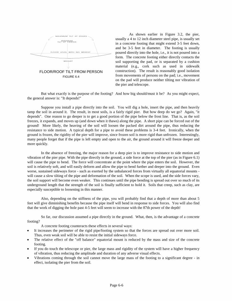
Page 6-6
As shown earlier in Figure 3.2, the pier, usually a 4 to 12 inch diameter steel pipe, is usually set in a concrete footing that might extend 3-5 feet down, and be 3-5 feet in diameter. The footing is usually poured directly into the hole, i.e., it is not poured into a form. The concrete footing either directly contacts the soil supporting the pad, or is separated by a cushion material (e.g., cork such as used in sidewalk construction). The result is reasonably good isolation from movements of persons on the pad; i.e., movement on the pad will produce neither tilting nor vibration of the pier and telescope.
But what exactly is the purpose of the footing? And how big should/must it be? As you might expect, the general answer is: "It depends!" Suppose you install a pipe directly into the soil. You will dig a hole, insert the pipe, and then heavily tamp the soil in around it. The result, in most soils, is a fairly rigid pier. But how deep do we go? Again, "it depends". One reason to go deeper is to get a good portion of the pipe below the frost line. That is, as the soil freezes, it expands, and moves up (and down when it thaws) along the pipe. A short pipe can be forced out of the ground! More likely, the heaving of the soil will loosen the packed dirt around the pipe, thus reducing the resistance to side motion. A typical depth for a pipe to avoid these problems is 3-4 feet. Ironically, when the ground is frozen, the rigidity of the pier will improve, since frozen soil is more rigid than unfrozen. Interestingly, many people forget that if the pipe is left empty and open to the air, the ground around it will freeze deeper and more quickly. In the absence of freezing, the major reason for a deep pier is to improve resistance to side motion and vibration of the pier pipe. With the pipe directly in the ground, a side force at the top of the pier (as in Figure 6.1) will cause the pipe to bend. The force will concentrate at the point where the pipe enters the soil. However, the soil is relatively soft, and will easily deform and allow the pipe to bend further and deeper into the ground. Even worse, sustained sideways force - such as exerted by the unbalanced forces from virtually all equatorial mounts - will cause a slow tilting of the pipe and deformation of the soil. When the scope is used, and the side forces vary, the soil support will become even weaker. This continues until the pipe bending is spread out over so much of its underground length that the strength of the soil is finally sufficient to hold it. Soils that creep, such as clay, are especially susceptible to loosening in this manner. Also, depending on the stiffness of the pipe, you will probably find that a depth of more than about 5 feet will give diminishing benefits because the pipe itself will bend in response to side forces. You will also find that the work of digging the hole past 4-5 feet will seem to increase with the 87th power of the depth! So far, our discussion assumed a pipe directly in the ground. What, then, is the advantage of a concrete footing? A concrete footing counteracts these effects in several ways: • It increases the perimeter of the rigid pipe/footing system so that the forces are spread out over more soil.
Thus, even weak soil will be able to resist the initial sideways force. • The relative effect of the "off balance" equatorial mount is reduced by the mass and size of the concrete
footing. • If you do touch the telescope or pier, the large mass and rigidity of the system will have a higher frequency
of vibration, thus reducing the amplitude and duration of any adverse visual effects. • Vibrations coming through the soil cannot move the large mass of the footing to a significant degree - in
effect, isolating the pier from the soil.
FLOOR/ROOF TILT FROM PERSON
FIGURE 6.4

Page 6-7
Before leaving the pier design, we should mention that a steel pipe is not the only feasible material for a pier. Another option is to construct a pier and footing of concrete block, tied together with reinforcing bar and small amounts of concrete. A more common approach is to pour concrete (or sand) into a tube or pipe made of plastic, cardboard, sheet metal, short lengths of concrete pipe, or other material. Such a pier can be constructed in one or multiple pours. The footing might be poured separately (as described in Chapter 3), and with the addition of reinforcing steel, the pier itself can be poured in a series of small pours to construct the height desired. You can also use piers made of wood. In most areas, such a pier (even in concrete) should be treated to resist rot. Be aware, however, that because wood is relatively flexible, you will need to use strong woods in large amounts to achieve a quality pier. All in all, the conventional wisdom is correct: a strong and massive pier and footing will give good results, and is always a desirable alternative. However, if you face constraints of money, access to concrete, or other factors, better understanding of the design tradeoffs will help you design a successful pier. Pier On
So, the idea is to fix the telescope pier directly to the surface of the concrete pad. A simple design would be a steel plate with leveling screws anchored to the pad. The pier column would be welded or bolted to the steel plate. Bad News: This design will be very vibration-prone, because a steel plate anchored at only three or four points is very subject to flexure. However, problem is also easy to fix. After leveling, one introduces grout (an expanding concrete) under the plate, thus providing support across the whole plate area, and preventing flexure. Alternatively, one can introduce leveling into the head of the mount itself so you can bolt the plate directly to the concrete (with grout or concrete to provide the continuous support needed to prevent flexure).
a Pad The designs using separate pads and piers discussed above work well, but may be more expensive and complex than needed. For example, if the pad is constructed at all well, there is usually little need for vibration damping and the pad will tilt very little as persons walk around. Thus, if the pad is stable, why not use it directly as a telescope foundation? Why pour 5-10 tons of concrete and not use it to support the telescope? Although this approach violates much pier mythology, if constructed following a few essential ideas, you may be able to use the pad (even a pad without footings) directly as the footing for the telescope. There are a few cautions. In an area where the soil under the pad can expand/contract with seasons (high clay content that swells with water getting under the pad, or freeze/thaw cycles), the pad may rise and fall by as much an inch. If the pad is not on uniform ground (e.g., was cut into a slope), it may experience a net tilt of a much as 1 in. in ten feet. This could produce as much as 0.5 deg. temporary shift in the telescope alignment. This would not affect visual or even most CCD work, but could adversely affect long time exposures and the ability of computer telescopes to find an object. Pad footings will largely solve the problem (they are often required by building codes, anyway). In addition to weather related pad shift, one would always be concerned about the effects of walking on the pad. As discussed above, the most common potential problem is the tilt of a pad resulting from the shift of a person’s weight from one side of the pad to another during an exposure. We have found that a well constructed pad/pier will typically show a tilt of about a second of arc, which is normally not a problem. Pad footings will likely help this problem, too.

Page 6-8
In any case, it is also important to have sufficient triangular gussets joining the column to the plate. Use three or four, preferably of steel. For a typical four foot column, they might be 10-12 in. away from the column at the base, and reach about 24-30 in. high. These can be either bolted or welded. An even easier pad-pier design is simply to rest the column on the pad (maybe with a simple centering pin or bolt). About 2/3 of the way up the column, attach three or four eyebolts (or simple brackets) around the perimeter. Attach three or four eyebolts into the pad a foot or so away from the column base, using standard concrete anchors. Then join the each of the upper and lower eyebolts with a piece of 3/8 steel rod and a turnbuckle (you can bend hooks onto the rods with a propane torch). You now have three (four) angled tie downs. You can adjust the level(vertical) of the column, and using the turnbuckles, you can fasten the column tightly to the pad. It is simple, inexpensive, easy to adjust or even remove, and very effective and very rigid because the tie-downs are under high tension. This is in fact the pier design we use. Pier and a Deck If the observatory is to be placed on, for example, a five-foot high deck, you might well have a separate pier down through a hole in the deck. The pier might be a steel pipe, column of concrete, or it might be built up using concrete block as described above. . However, suppose for some reason you cannot build a pier down to the ground and you need to have the pier supported by the deck itself. You would probably design the deck support structure to be as open as possible so that wind forces would have relatively little effect. In addition, you might deliberately design the deck so that its sideways movements result in translation, rather than rotation of the floor. For example, if the deck is supported on parallel vertical posts, you could install deck fastenings that are designed to flex. As shown in Figure 6.5, pressure of the wind will then tend to bend the deck supports, but the deck will tend to move sideways, rather than tilt. Thus, within limits, "loose" or flexible fastenings may be superior to "tight" fastenings!
In theory, one could build the pier itself of four relatively small pipes with a pier head designed to stay level in the presence of sideways pier forces. Such a design would require great care, because changes in the center of gravity of the scope as the scope follows the stars might introduce tracking errors if the pier head flexes. Keep in mind that this approach is not generally preferable to a more conventional rigid, massive pier and footing. However, if circumstances prevent a conventional pier design, this type of approach may lead to a pier design that satisfies your needs.
Examples of On-Building Pier Designs For most IN-roof or ON-roof installations, you will want a pier that is at least partly isolated from the observing floor and dome structural support. You can accomplish this in several ways. The most straightforward isolated pier for an on-house installation is a vertical pier constructed independent of the floor, with the pier reaching from the base of the telescope into the ground to bedrock or a firm base as shown in Figure 6.6. Such a pier is sometimes very easy to fit into a building (e.g., down between the cars in a two car garage), but in other cases, requires either creative thinking or a changed set of values. Can your family accept a steel pipe down through the middle of the living room? A tall pier reaching to an upper floor may require cables or rods to stiffen it and help prevent sway or vibration.
MAGIC DECK OR PIER
FIGURE 6.5

Page 6-9
If you do have a tall pier, such as needed to reach to a second floor, it will have a low frequency of vibration (often slower than once per second), a relatively high Q (perhaps ten or more), and a relatively unstable direction (small earth movements or temperature shifts tilt or bend the pipe). These characteristics can result in a long duration of oscillation lasting many seconds while the pier swings back and forth after you touch the scope. However, even with a low frequency of vibration, you may be able to achieve success if you provide appropriate damping, i.e., lower the Q. For example, one astronomer having a tall pier uses a circle of carpet surrounding the pipe. The carpet dampens the pier oscillation, yet does not transmit vertical movement of the floor to the pier. This is a very simple and elegant solution even though the whole installation violates most pier mythology.
If you use a pipe for the pier, you can easily increase the rigidity and increase the frequency of vibration by filling the pipe with concrete. The stiffness of concrete more than offsets the larger weight which would cause slower vibration. A different approach is to fill the pipe with sand to increase the damping and to stiffen the pipe. In this solution, the sand grains rub together to dissipate the energy of vibration, thus reducing the Q of the pier. Both approaches seem to work well. Rather than construct a pier completely separate from the foundation structure, another approach for on-house installations is to construct a pier that is only partially isolated from the house. A pier tied into the wall structure, but isolated from the floor holding the dome and astronomer, will be isolated from virtually all the personal movement (which is usually the major problem), while still providing a stiff support. Properly designed, it would be immune from all but actual tilts of the house and very slow weather related changes in dimensions of the house structure. Let's assume your house has an observatory resting on a wood floor built of 2x10 joists. You can build a semi-isolated pier on a pair of 2x6s (or steel beams) supported at the walls of the room (i.e., tied into the house structural members forming the base of the wall). The 2x6s supporting your pier would extend across the middle of the room, but would be raised off the floor. If you used two pairs of 2x6s at right angles, then the pier would have stiffness against tilting in both East-west or North-south directions. Of course, 2x6s above the floor will introduce some real impediments for your astronomy! However, such a structure is entirely feasible if built below the ceiling in the room below the observatory, with the pier projecting up through a hole in the floor. A more elegant solution is to take advantage of the floor joists being on 16 in. centers, giving space between them for a separate pier support as shown in Figure 6.7. This will let you work between the floor and the ceiling below. You can remove a portion of the floor to expose the lengths of two floor joists. Then insert two or more 2x8s or other
DOME/PIER FOUNDATION SUPPORT DESIGNS
FIGURE 6.6
PIER WITHIN FLOOR STRUCTURE
FIGURE 6.7

Page 6-10
members between the joists, allowing vertical clearance from both the observatory floor and the ceiling below. The pier support joists must be strongly cross-braced, so that the pier cannot flex or twist easily side to side. For a stronger design, use steel structural members, instead of wood. You may also want to skip across several joists so that the pier is supported by a much wider “footprint”, thus giving improved support against vibration in both directions. Support the ends of the new beams at the walls. You can then replace all the flooring, except for a hole for the base of the pier. The result is an independent support for the pier, not directly affected by movements of the observer on the floor in the immediate area. When using these techniques, it may be desirable not to connect the pier beams rigidly into the wall structure. Rather, you might simply rest the beams on supports at each wall as shown in Figure 6.8, so that twisting of the house wall structural members will not cause the pier support beams to twist or tilt. Thus, even as the house "bends over" in the wind, the twisting of the wall will not (to first order) tilt or twist the pier beams. Pier Fabrication We have been discussing various schemes for pier installation. However, a more immediate problem for many people is finding the material and accomplishing the machine work necessary for the pier itself. There are two parts to fabricate (1) the pier or column itself, and (2), the head or cap on the pier that will accommodate your telescope mount. You can have a local machine shop or blacksmith construct the pier and pier head; however, you may want to do more of the work yourself. You will not need special tools or skills to construct a concrete pier by filling a pipe or other form with concrete. However, how do you even find the steel pipe for the pier? And what kinds of pipes are suitable for piers? Steel pipe is used in plumbing as well as in building structures, and comes in a wide variety of diameters, wall thickness, and strengths. Various types of steel are available, including black iron, galvanized iron, and stainless steel. While we emphasize steel pipe, you may find aluminum or other materials entirely suitable.
A typical pipe for a pier might be 4-8 in. diameter, with a wall thickness of at least 1/4 in. The length needed will depend on how deep a hole you are willing to dig (say, 4 ft.), and the type of telescope and mounting. A typical aboveground pier height might be three feet for a ten-inch Schmidt-Cassegrain. Thus a pipe length of about seven feet is what is needed. If you buy new pipe, you will probably have to buy a 20-foot minimum (and it weighs a lot, so transport is not trivial). The best alternative is to use second hand pipe. Good sources include junk yards, recycling businesses, scrap metal dealers, plumbers, and construction companies. We've seen great prices even for stainless pipe at our own favorite junkyard called - what else, "Reliable Junk" in Frederick, Md. Another excellent source or second hand pipe is a well drilling company: well casing is perfect for piers.
The supplier of the pipe can often cut the pipe for you. However, be aware that they may cut it using a torch or other means that leaves a very rough edge. While this is fine for the lower end of the pipe, you will want a reasonably good edge at the top. You can also cut the pipe yourself with a hacksaw. Use good blades, and lots of oil. You will find that the cutting goes pretty quickly, e.g., a six-inch pipe can be cut in about ten minutes. The easiest way to remove bumps or to square off the end of the pipe (assuming you do not have a large lathe) is to grind the end with a hand-held angle grinder. This very useful power tool can be purchased for under $100, or rented by the hour. Use eye and ear protection, and watch the sparks fly! With care, you can grind the end of the pipe not only smooth, but square to the pipe axis to as good an accuracy as you can measure (better than 0.01 inch).
PIER STRUCTURE
WALL CONNECTION FIGURE 6.8

Page 6-11
The second component of a pier is the head, which holds the telescope mount. The head should include some leveling adjustments to compensate for a pier that is not quite vertical. The detailed head design will depend on the mounting requirements for your telescope mount. However, most mounts have central pivot bolt of about 1/2 in. diameter, and several additional bolts for use after the mount is aligned. If you have a tripod, you should use its head as the pattern for your pier head. Now the challenge is to obtain the head material, shape it, drill mounting holes, and attaching it to the pier pipe. The same shops and businesses you visited for the pipe are good sources for the pier head material. A good material to use is steel plate, 1/2 inch thick, preferably in a circular shape an inch or so bigger than your pier pipe. Aluminum plate is also suitable. It is easier to work than steel, but not as rigid. Aluminum cannot be welded to steel, so your pier head attachment options are more limited. Whatever the material, you may find it much easier and cheaper to use a square plate, then using your grinder to round the corners. A standard drill press, 1/2-in. bit, and plenty of oil will give you the holes needed. But how do you attach the head to the pier pipe? You might want to construct the head on a threaded coupling, and simply screw it onto the pipe. With good design, this approach is great, except that in most areas it is extremely difficult to find places that will thread pipe more than 3 to 4 inches in diameter. Another option, and often the best solution, is to weld the head onto the pipe using either electric or gas welding. However, modifications will be difficult if you make a mistake, if the pier is not vertical, or if you later want to change the head or add a length of pipe to increase the pier height.
An alternative is to bolt the head to the pipe. There are a variety of methods. You can make simple L-brackets using 1x1/8 in. steel bar, and use 5/16-in. bolts to fasten the parts together. The L-brackets can be mounted on the outside of the pipe. However, you can make a neater job if you thread the holes in the L-bracket. Then you can put the brackets inside the pipe, and use bolts inserted from the outside. In both cases, oversize mounting holes will give you some latitude for leveling the head.
If you can leave all or part of your pier pipe empty, you can run power wires up the inside, and have a very convenient power outlet on the pier. You can also drill and thread holes at later times so you can mount other things to the pier (e.g., eyepiece tray, electronics, bracket to hold telescope control, etc.). Finally, if you do have metal pier, you should remember to ground it to reduce any risk of shock, or of electronic interference. Summary Many astronomy applications require a very strong, very rigid pier system, but others do not. While a strong, rigid pier is easy to construct in an on-the-ground observatory, it may be very difficult for an on-house installation. However, even on a house, it may be feasible to use the existing structure to support both the observing floor and the pier. It is also feasible to construct isolated piers, even on the upper floors of homes. You can have a local machine shop construct the pier and pier head, or you can find the material and do it yourself, without special tools, and at low expense.
ALTERNATIVE PIER HEADS
FIGURE 6.9

TECHNICAL INNOVATIONS 7851 Cessna Ave.
Gaithersburg, MD 20879 301-977-9000 FAX 301-977-1106
OBSERVATORY DIMENSION WORKSHEET
This worksheet will help you select the diameter and other dimensions of your HOME-DOME® or PRO-DOME™ observatory, based on your telescope and the way you plan to use the dome. You can use this sheet in three ways: • Use suggested Sizes. We've provided a table showing typical dome sizes for several common telescope types and sizes. • Do-it-yourself. We give directions to estimate the size dome and walls you will need. • Send-it-to-us. Write down all the information requested in the tables and send the form to us for suggestions.. We emphasize that the design of your observatory must reflect your particular needs and values. The estimates on this sheet do NOT take into account special requirements for institutional users, including the need for handicap access (" The Americans with Disabilities Act") or the desirability of relatively high walls. In any case, please call or write to us for assistance in planning your observatory. And don't forget our book "At Home in a Dome," which will help you evaluate various observatory design issues. Observatory Sizing Factors The diameter and wall height of the observatory depend on the physical space needed by the telescope and the people using it. These include • The height of the observatory wall should be low enough so that the telescope can see down to the horizon. It must be high enough
for the scope to swing up to zenith without touching the dome. • The dome diameter must be large enough so the telescope can point in all directions. • The dome diameter should allow at least two feet around the telescope for a single user, but more if multiple persons or substantial
equipment will be present. 1. Suggested Sizes. This table shows several of the more common telescopes and mountings, and gives suggested dome and wall measurements for each. The two columns on the right give recommendations for two cases: (1), only one user most of the time,and little need for equipment or work space, and (2), if groups use the dome, or if there is need for work tables, storage, or equipment space. In either case, the wall heights will be the same.
Scope Type Mounting Typical Total Wall
Height
Number of Extra Rings
Suggested Dome Diameter One User Multi-user
Schmidt-Cass up to 10 in. or Refractor less than 36 in. long
Yoke or German 3-4 ft. 2-3 6 ft. 10 ft
Schmidt-Cass up to 16 in. Yoke or German 3-4 ft. 2-3 10 ft 15 ft Newtonian up to 14 in. German 3-4 ft. 2-3 10 ft 15 ft Newtonian over 14 in. German 4-ft. 3-4 15 ft 15 ft Newtonian/Dobsonian Yoke 1-2 ft. 0-1 dome dia=2 x tube length Refractor tube length up to 5 ft. German 5-6 ft 4-5 10 ft 15 ft
2. Do-It -Yourself. Using the telescope cartoons on the next page, identify the type of mounting that fits your situation. If you can set up your scope and mounting, measure the dimensions listed below. If you cannot set up the scope, use drawings from the manufacturer or photos to estimate the dimensions. The measurements you need are: D--Optical Diameter of the Scope (objective or mirror diameter) L--Physical length of the scope, excluding the eyepiece holder W--Height above the floor of the lower edge of the scope when the scope is horizontal H--Maximum height above the floor when the scope is vertical

The total wall height will be equal to W if you wish to see down to the horizon. Because a PRO-DOME or HOME-DOME® includes a one foot height base ring, the additional wall needed is W minus one foot. The radius of the minimum size dome to accommodate your scope will be H minus W. Multiply by two for the minimum diameter. The actual size of your observatory must allow for people as well as the telescope. The observer and visitors must be able to move around without bumping the telescope, and space is needed for a storage cabinet, electronics, table, etc. If the telescope is a Newtonian, space is needed near the "top" end for the person's head at the eyepiece, and floor space is likely needed for a ladder of some type. If the observatory will usually have only one person inside, add three to four feet to the minimum domediameter needed for the telescope. This gives 1 1/2 to 2 feet for your body on any side of the scope.) With less space than that, you increase the risk of bumping the scope while moving around, and will have little space for working. If the observatory will frequently contain groups of people, you will need even more added diameter (especially in cold weather). Your final dome diameter equals the minimum diameter plus allowance for people. Example. Assume the minimum dome diameter for your telescope is five feet. If several people will frequently be present in the dome, you might allow three feet on all sides of the telescope. Three feet on each side adds six feet to the diameter. Thus, the total diameter needed is five plus six or eleven feet. This shows that a ten foot diameter dome will be a little on the tight side, while a fifteen foot diameter will provide more than sufficient space. The choice between the two will then be a matter of your own judgment. 3. Send it to us. We can advise you on dome size if you fill in the table below, and send it to us. We will review the information, and make recommendations for your observatory. If your telescope, mounting, or use is relatively unusual, or if the telescope will be a tight "squeeze" into the dome, we may need to talk to you in more detail, and may carry out additional analysis to help you in your decision. Brand of Scope and Model Type (Newtonian, Refractor, S-C, Dobsonian, etc.) Physical Tube Diameter Type of Mount D = L = W = H = Number persons usually present. Types of Use (visual astronomy, photos, CCD, group instruction, research, etc.) Amount of extra equipment present
worksheet2