76-100 SERIES STAINLESS STEEL BALL VALVE W ......• Meets NACE MR0175 (2000) & MR0103 (2012) •...
8
A-14 Customer Service (704) 841-6000 www.apolloflowcontrols.com “Apollo” Flow Controls FEATURES • Investment cast components • Reinforced seats • Mounting pad for easy actuator mounting • Blowout-proof stem design • Adjustable packing gland • Stainless steel lever and nut • Fire safe to API 607 (requires -24 suffix) • Meets NACE MR0175 (2000) & MR0103 (2012) • CSA CGA 3.16-M88 (Requires “GS” suffix) • NSF/ANSI 61 Section 8, Annex G • NSF-372, Drinking Water System Components - Lead Content STANDARD MATERIAL LIST PART MATERIAL 1 Lever and grip 304 SS w/vinyl 2 Stem packing MPTFE 3 Stem bearing RPTFE 4 Ball A276-316 Stainless Steel 5 Seat (2) RPTFE 6 Retainer A351-CF8M SS or A276-316 SS 7 Gland nut A276-316 Stainless Steel 8 Stem A276-316 Stainless Steel 9 Lever nut 18-8 Stainless Steel 10 Body seal PTFE 11 Body A351-CF8M Stainless Steel OPTIONS AVAILABLE: (MORE INFORMATION IN SECTION J) • Minimum quantities apply • To specify an option, replace the “01” standard suffix with the suffix of the option. • To specify multiple options, replace the “01” suffix with the desired suffixes in the numerical order shown below. NOTE: Not all suffixes can be combined together. (SUFFIX) OPTION SIZES -01 Standard Configuration All -P -01- BSPP (Parallel) Thread Connection 1/4” to 3” -T -01- BSPT (Tapered) Thread Connection 1/4” to 3” -02- Stem Grounded 1/4” to 3” -04- 2.25” Stem Extension (Carbon Steel, Zinc Plated) 1/4” to 3” -07- Steel Tee Handle 1/4” to 2” -08- 90º Reversed Stem 1/4” to 3” -14- Side Vented Ball (Uni-Directional) 1/4” to 2” -15- Wheel Handle, Steel 1/4” to 2” -16- Chain Lever - Vertical 3/4” to 2” -19- Lock Plate 1/4” to 2” -21- UHMWPE Trim (Non-PTFE) 1/4” to 3” -24- Graphite packing, PTFE body seal, RPTFE bearing (Fire Safe API 607, 6th edition, ISO 10497:2010) 1/4” to 3” -27- SS Latch-Lock Lever & Nut 1/4” to 3” -30- Cam-Lock and Grounded 1/4” to 2” -32- SS Tee Handle & Nut 1/4” to 2” -35- PTFE Trim 1/4” to 3” -39- SS Hi-Rise Locking Wheel Handle, SS Nut 1/4” to 2” -40- Cyl-Loc and Grounded 1/4” to 2” -44- Seal Welded 1/4” to 2” -45- Less Lever & Nut 1/4” to 3” -46- Latch Lock Lever - Lock in Closed Position Only 1/4” to 3” -47- SS Latch Lock Oval Handle 1/4” to 2” -48- SS Oval Handle (No Latch) & Nut 1/4” to 2” -49- No Lubrication. Assembled Dry. 1/4” to 3” -50- 2.25” CS Locking Stem Extension 1/4” to 3” -57- Oxygen Cleaned 1/4” to 3” -58- Chain Lever - Horizontal 3/4” to 2” -60- Static Grounded Ball & Stem 1/4” to 3” -64- 250# Steam Trim (MPTFE Seats & Packing) 1/4” to 3” -GS CSA CGA 3.16 All Pressure/Temperature Ratings - Page M-14, Graph No. 14 DIMENSIONS PRODUCT NUMBER SIZE A B C D E F G H J K L M N WT. 76-101-01A 1/4” 0.37 1.02 2.05 1.71 3.85 0.50 1.12 0.88 0.34 0.53 0.375 0.234 1.16 0.58 76-102-01A 3/8” 0.37 1.02 2.05 1.71 3.85 0.50 1.12 0.88 0.34 0.53 0.375 0.234 1.16 0.55 76-103-01A 1/2” 0.50 1.12 2.23 1.79 3.85 0.50 1.12 0.90 0.34 0.59 0.375 0.234 1.38 0.63 76-104-01A 3/4” 0.68 1.47 2.96 2.03 4.75 0.87 1.37 1.02 0.42 0.78 0.437 0.256 1.75 1.30 76-105-01A 1” 0.87 1.67 3.34 2.16 4.75 0.87 1.37 1.02 0.42 0.91 0.437 0.256 1.94 1.60 REV. 11APR16 76-100 SERIES STAINLESS STEEL BALL VALVE W/ MOUNTING PAD (1/4” - 1”) Female NPT Thread, 2000 CWP (psig). Cold Non-Shock. (See referenced P/T chart) 150 psig Saturated Steam. Vacuum Service to 29 inches Hg. MSS SP-110 compliant. * LEAD FREE: The wetted surfaces of this product shall contain no more than 0.25% lead by weighted average. Complies with Federal Public Law 111-380. ANSI 3rd party approved and listed.
Transcript of 76-100 SERIES STAINLESS STEEL BALL VALVE W ......• Meets NACE MR0175 (2000) & MR0103 (2012) •...

A-14Customer Service (704) 841-6000 www.apolloflowcontrols.com
“Apollo” Flow Controls
FEATURES• Investment cast components • Reinforced seats • Mounting pad for easy actuator mounting • Blowout-proof stem design • Adjustable packing gland• Stainless steel lever and nut
• Fire safe to API 607 (requires -24 suffix)• Meets NACE MR0175 (2000) & MR0103 (2012)• CSA CGA 3.16-M88 (Requires “GS” suffix)• NSF/ANSI 61 Section 8, Annex G• NSF-372, Drinking Water System Components - Lead Content
STANDARD MATERIAL LISTPART MATERIAL
1 Lever and grip 304 SS w/vinyl2 Stem packing MPTFE3 Stem bearing RPTFE4 Ball A276-316 Stainless Steel5 Seat (2) RPTFE6 Retainer A351-CF8M SS or A276-316 SS7 Gland nut A276-316 Stainless Steel8 Stem A276-316 Stainless Steel9 Lever nut 18-8 Stainless Steel10 Body seal PTFE11 Body A351-CF8M Stainless Steel
OPTIONS AVAILABLE: (MORE INFORMATION IN SECTION J)• Minimum quantities apply• To specify an option, replace the “01” standard suffix with the suffix of the option.• To specify multiple options, replace the “01” suffix with the desired suffixes in the
numerical order shown below. NOTE: Not all suffixes can be combined together.
(SUFFIX) OPTION SIZES-01 Standard Configuration All
-P -01- BSPP (Parallel) Thread Connection 1/4” to 3”-T -01- BSPT (Tapered) Thread Connection 1/4” to 3”
-02- Stem Grounded 1/4” to 3”-04- 2.25” Stem Extension (Carbon Steel, Zinc Plated) 1/4” to 3”-07- Steel Tee Handle 1/4” to 2”-08- 90º Reversed Stem 1/4” to 3”-14- Side Vented Ball (Uni-Directional) 1/4” to 2”-15- Wheel Handle, Steel 1/4” to 2”-16- Chain Lever - Vertical 3/4” to 2”-19- Lock Plate 1/4” to 2”-21- UHMWPE Trim (Non-PTFE) 1/4” to 3”
-24- Graphite packing, PTFE body seal, RPTFE bearing (Fire Safe API 607, 6th edition, ISO 10497:2010)
1/4” to 3”
-27- SS Latch-Lock Lever & Nut 1/4” to 3”-30- Cam-Lock and Grounded 1/4” to 2”-32- SS Tee Handle & Nut 1/4” to 2”-35- PTFE Trim 1/4” to 3”-39- SS Hi-Rise Locking Wheel Handle, SS Nut 1/4” to 2”-40- Cyl-Loc and Grounded 1/4” to 2”-44- Seal Welded 1/4” to 2”-45- Less Lever & Nut 1/4” to 3”-46- Latch Lock Lever - Lock in Closed Position Only 1/4” to 3”-47- SS Latch Lock Oval Handle 1/4” to 2”-48- SS Oval Handle (No Latch) & Nut 1/4” to 2”-49- No Lubrication. Assembled Dry. 1/4” to 3”-50- 2.25” CS Locking Stem Extension 1/4” to 3”-57- Oxygen Cleaned 1/4” to 3”-58- Chain Lever - Horizontal 3/4” to 2”-60- Static Grounded Ball & Stem 1/4” to 3”-64- 250# Steam Trim (MPTFE Seats & Packing) 1/4” to 3”-GS CSA CGA 3.16 All
Pressure/Temperature Ratings - Page M-14, Graph No. 14DIMENSIONSPRODUCT NUMBER SIZE A B C D E F G H J K L M N WT.
76-101-01A 1/4” 0.37 1.02 2.05 1.71 3.85 0.50 1.12 0.88 0.34 0.53 0.375 0.234 1.16 0.5876-102-01A 3/8” 0.37 1.02 2.05 1.71 3.85 0.50 1.12 0.88 0.34 0.53 0.375 0.234 1.16 0.5576-103-01A 1/2” 0.50 1.12 2.23 1.79 3.85 0.50 1.12 0.90 0.34 0.59 0.375 0.234 1.38 0.6376-104-01A 3/4” 0.68 1.47 2.96 2.03 4.75 0.87 1.37 1.02 0.42 0.78 0.437 0.256 1.75 1.3076-105-01A 1” 0.87 1.67 3.34 2.16 4.75 0.87 1.37 1.02 0.42 0.91 0.437 0.256 1.94 1.60
REV. 11APR16
76-100 SERIESSTAINLESS STEEL BALL VALVE W/ MOUNTING PAD (1/4” - 1”)
Female NPT Thread, 2000 CWP (psig). Cold Non-Shock. (See referenced P/T chart)150 psig Saturated Steam.Vacuum Service to 29 inches Hg.MSS SP-110 compliant.
* LEAD FREE: The wetted surfaces of this product shall contain no more than 0.25% lead by weighted average. Complies with Federal Public Law 111-380. ANSI 3rd party approved and listed.

A-15Customer Service (704) 841-6000industrial.apollovalves.com
“Apollo” Flow Controls
Female NPT Thread, 1500 CWP (psig). Cold Non-Shock. (See referenced P/T chart)150 psig Saturated Steam.Vacuum Service to 29 inches Hg.MSS SP-110 compliant.
FEATURES• Investment cast components • Reinforced seats • Mounting pad for easy actuator mounting • Blowout-proof stem design • Adjustable packing gland• Stainless steel lever and nut
• Fire safe to API 607 (requires -24 suffix)• Meets NACE MR0175 (2000) & MR0103 (2012)• CSA CGA 3.16-M88 (Requires “GS” suffix)• NSF/ANSI 61 Section 8, Annex G• NSF-372, Drinking Water System Components - Lead Content
OPTIONS AVAILABLE: (MORE INFORMATION IN SECTION J)• Minimum quantities apply• To specify an option, replace the “01” standard suffix with the suffix of the option.• To specify multiple options, replace the “01” suffix with the desired suffixes in the • numerical order shown below. NOTE: Not all suffixes can be combined together.
(SUFFIX) OPTION SIZES-01 Standard Configuration All
-P -01- BSPP (Parallel) Thread Connection 1/4” to 3”-T -01- BSPT (Tapered) Thread Connection 1/4” to 3”
-02- Stem Grounded 1/4” to 3”-04- 2.25” Stem Extension (Carbon Steel, Zinc Plated) 1/4” to 3”-07- Steel Tee Handle 1/4” to 2”-08- 90º Reversed Stem 1/4” to 3”-14- Side Vented Ball (Uni-Directional) 1/4” to 2”-15- Wheel Handle, Steel 1/4” to 2”-16- Chain Lever - Vertical 3/4” to 2”-19- Lock Plate 1/4” to 2”-21- UHMWPE Trim (Non-PTFE) 1/4” to 3”
-24- Graphite packing, PTFE body seal, RPTFE bearing (Fire Safe API 607, 6th edition, ISO 10497:2010)
1/4” to 3”
-27- SS Latch-Lock Lever & Nut 1/4” to 3”-30- Cam-Lock and Grounded 1/4” to 2”-32- SS Tee Handle & Nut 1/4” to 2”-35- PTFE Trim 1/4” to 3”-39- SS Hi-Rise Locking Wheel Handle, SS Nut 1/4” to 2”-40- Cyl-Loc and Grounded 1/4” to 2”-44- Seal Welded 1/4” to 2”-45- Less Lever & Nut 1/4” to 3”-46- Latch Lock Lever - Lock in Closed Position Only 1/4” to 3”-47- SS Latch Lock Oval Handle 1/4” to 2”-48- SS Oval Handle (No Latch) & Nut 1/4” to 2”-49- No Lubrication. Assembled Dry. 1/4” to 3”-50- 2.25” CS Locking Stem Extension 1/4” to 3”-57- Oxygen Cleaned 1/4” to 3”-58- Chain Lever - Horizontal 3/4” to 2”-60- Static Grounded Ball & Stem 1/4” to 3”-64- 250# Steam Trim (MPTFE Seats & Packing) 1/4” to 3”-GS CSA CGA 3.16 All
STANDARD MATERIAL LISTPART MATERIAL
1 Lever and grip 304 SS w/vinyl2 Stem packing MPTFE3 Stem bearing RPTFE4 Ball A276-316 Stainless Steel5 Seat (2) RPTFE6 Retainer A351-CF8M Stainless Steel7 Gland nut A276-316 Stainless Steel8 Stem A276-316 Stainless Steel9 Lever nut 18-8 Stainless Steel10 Body seal PTFE11 Body A351-CF8M Stainless Steel
Pressure/Temperature Ratings - Page M-13, Graph No. 12DIMENSIONS
PRODUCT NUMBER SIZE A B C D E F G H J K L M WT.
76-106-01 1.25” 1.00 2.00 4.00 2.68 5.40 0.94 1.50 1.50 0.60 1.12 0.625 0.377 3.1076-107-01 1.5” 1.25 2.17 4.34 3.25 7.75 0.94 1.50 1.50 0.60 1.28 0.625 0.377 4.2076-108-01 2” 1.50 2.69 5.43 3.24 7.75 0.94 1.50 1.46 0.60 1.50 0.625 0.377 6.10
REV. 11APR16
76-100 SERIESSTAINLESS STEEL BALL VALVE W/ MOUNTING PAD (1-1/4” - 2”)
* LEAD FREE: The wetted surfaces of this product shall contain no more than 0.25% lead by weighted average. Complies with Federal Public Law 111-380. ANSI 3rd party approved and listed.

A-16Customer Service (704) 841-6000 www.apolloflowcontrols.com
“Apollo” Flow Controls
Female NPT Thread, 1000 CWP (psig). Cold Non-Shock. (See referenced P/T chart)150 psig Saturated Steam.Vacuum Service to 29 inches Hg.MSS SP-110 compliant.
FEATURES• Investment cast components • Reinforced seats • Mounting pad for easy actuator mounting • Blowout-proof stem design • Adjustable packing gland• Stainless steel lever and nut
• Fire safe to API 607 (requires -24 suffix)• Meets NACE MR0175 (2000) & MR0103 (2012)• CSA CGA 3.16-M88 (Requires “GS” suffix)• NSF/ANSI 61 Section 8, Annex G• NSF-372, Drinking Water System Components - Lead Content
OPTIONS AVAILABLE: (MORE INFORMATION IN SECTION J)• Minimum quantities apply• To specify an option, replace the “01” standard suffix with the suffix of the option.• To specify multiple options, replace the “01” suffix with the desired suffixes in the
numerical order shown below. NOTE: Not all suffixes can be combined together.
(SUFFIX) OPTION SIZES-01 Standard Configuration All
-02- Stem Grounded 1/4” to 3”-04- 2.25” Stem Extension (Carbon Steel, Zinc Plated) 1/4” to 3”-07- Steel Tee Handle 1/4” to 2”-08- 90º Reversed Stem 1/4” to 3”-14- Side Vented Ball (Uni-Directional) 1/4” to 2”-15- Wheel Handle, Steel 1/4” to 2”-16- Chain Lever - Vertical 3/4” to 2”-19- Lock Plate 1/4” to 2”-21- UHMWPE Trim (Non-PTFE) 1/4” to 3”
-24- Graphite packing, PTFE body seal, RPTFE bearing (Fire Safe API 607, 6th edition, ISO 10497:2010)
1/4” to 3”
-27- SS Latch-Lock Lever & Nut 1/4” to 3”-30- Cam-Lock and Grounded 1/4” to 2”-32- SS Tee Handle & Nut 1/4” to 2”-35- PTFE Trim 1/4” to 3”-39- SS Hi-Rise Locking Wheel Handle, SS Nut 1/4” to 2”-40- Cyl-Loc and Grounded 1/4” to 2”-44- Seal Welded 1/4” to 2”-45- Less Lever & Nut 1/4” to 3”-46- Latch Lock Lever - Lock in Closed Position Only 1/4” to 3”-47- SS Latch Lock Oval Handle 1/4” to 2”-48- SS Oval Handle (No Latch) & Nut 1/4” to 2”-49- No Lubrication. Assembled Dry. 1/4” to 3”-50- 2.25” CS Locking Stem Extension 1/4” to 3”-57- Oxygen Cleaned 1/4” to 3”-58- Chain Lever - Horizontal 3/4” to 2”-60- Static Grounded Ball & Stem 1/4” to 3”-64- 250# Steam Trim (MPTFE Seats & Packing) 1/4” to 3”-GS CSA CGA 3.16 All
Pressure/Temperature Ratings - Page M-12, Graph No. 8
STANDARD MATERIAL LISTPART MATERIAL
1 Lever and grip 304 SS w/vinyl2 Stem packing MPTFE3 Stem bearing RPTFE4 Ball A276-316 Stainless Steel5 Seat (2) RPTFE6 Retainer A351-CF8M Stainless Steel7 Gland nut A276-316 Stainless Steel8 Stem A276-316 Stainless Steel9 Lever nut 18-8 Stainless Steel10 Body seal PTFE11 Body A351-CF8M Stainless Steel
DIMENSIONSPRODUCT NUMBER SIZE A B C D E F G H J K L M WT.
76-109-01 2.5” 2.50 3.38 6.75 4.03 7.75 1.38 3.37 1.71 0.60 2.00 0.625 0.377 15.6076-100-01 3” 2.50 3.38 6.75 4.03 7.75 1.38 3.37 1.71 0.60 2.00 0.625 0.377 16.50
REV. 11APR16
76-100 SERIESSTAINLESS STEEL BALL VALVE W/ MOUNTING PAD (2-1/2” - 3”)
* LEAD FREE: The wetted surfaces of this product shall contain no more than 0.25% lead by weighted average. Complies with Federal Public Law 111-380. ANSI 3rd party approved and listed.

M-3Customer Service (704) 841-6000industrial.apollovalves.com
“Apollo” Flow Controls
The listed Cv “factors” are derived from actual flow testing, in the Apollo® Ball Valve Division, Conbraco Industries, Inc., Pageland, South Carolina. These tests were completed using standard “off the shelf” valves with no special preparation and utilizing standard schedule 40 pipe. It should be understood that these factors are for the valve only and also include the connection configuration. The flow testing is done utilizing water as a fluid media and is a direct statement of the gallons of water flowed per minute with a 1 psig pressure differential across the valve/connection unit. Line pressure is not a factor. Because the Cv is a factor, the formula can be used to estimate flow of most media for valve sizing.
Cv FACTORS FOR APOLLO VALVES (continued on M-4)
VALVE SIZE (IN.)1/4 3/8 1/2 3/4 1 1.25 1.5 2 2.5 3 4 6 8 10 12
70B-140 Series 8.4 7.2 15 30 43 48 84 108 190 370 670 -- -- -- --70-100/200 Series 8.4 7.2 15 30 43 48 84 108 190 370 670 -- -- -- ---70-300/400 Series -- -- 15 30 43 48 84 108 -- -- -- -- -- -- --
70-600 Series 2.3 4.5 5.4 12 14 21 34 47 -- -- -- -- -- -- --70-800 Series 8.4 7.2 15 30 43 48 84 -- -- -- -- -- -- -- --71-AR Series -- -- -- 30 43 48 84 108 190 370 -- -- -- -- --
71-100/200 Series -- -- -- 30 43 48 84 108 190 370 -- -- -- -- --72-100/900 Series -- -- 26 48 65 125 170 216 -- -- -- -- -- -- --
72-1xx-A/72-9xx-A Series -- -- 26 48 65 125 170 245 -- -- -- -- -- -- --73A-100 Series 8.4 7.2 15 30 43 48 84 108 -- -- -- -- -- -- --
73-300/400 Series -- -- 26 48 65 125 170 216 -- -- -- -- -- -- --74-100 Series 8.4 7.2 15 30 43 48 84 108 190 370 670 -- -- -- --75-100 Series 8.4 7.2 15 30 43 48 84 108 190 370 670 -- -- -- --76-AR Series 8.4 7.2 15 30 43 48 84 108 190 370 670 -- -- -- --
76F-100 Series 8.1 15 15 51 68 125 177 389 -- -- -- -- -- -- --76FJ-100 Series 8.1 15 15 51 68 125 177 389 -- -- -- -- -- -- --76FK-100 Series 8.1 15 15 51 68 125 177 389 -- -- -- -- -- -- --
76-100 Series 8.4 7.2 15 30 43 48 84 108 190 370 -- -- -- -- --76-300/400 Series -- -- 26 48 65 125 170 216 -- -- -- -- -- -- --
76-600 Series 2.3 4.5 5.4 12 14 21 34 47 -- -- -- -- -- -- --76J-100 Series 8.4 7.2 15 30 43 48 84 108 190 370 -- -- -- -- --76J-AR Series 8.4 7.2 15 30 43 48 84 108 190 370 670 -- -- -- --76K-100 Series 8.4 7.2 15 30 43 48 84 108 190 370 -- -- -- -- --76K-AR Series 8.4 7.2 15 30 43 48 84 108 190 370 670 -- -- -- --7K-100 Series -- -- 15 51 68 125 177 389 503 -- -- -- -- -- --77-AR Series 8.1 15 15 51 68 -- 177 389 -- -- -- -- -- -- --
∆PSpGr
Q = CV√FLOW OF LIQUID
WHERE:• Q = Flow in US gpm• ∆P = Pressure drop (psig)• SpGr = Specific gravity at flowing temperature• Cv = Valve constant
FLOW OF GAS
WHERE:• Q = Flow in SCFH• ∆P = Pressure drop (psig)• SpGr = Specific gravity (based on air = 1.0)• P2 = Outlet pressure–psia (psig + 14.7)• T = (temp. °F + 460)• Cv = Valve constant
(Q)2 (SpGr)(Cv)
2 or ∆P =
(∆P) (P2)(SpGr) (T)
Q = 1360 CV √5.4 x 10⁻⁷ (SpGr) (T) (Q)2
(Cv)2 (P2) or ∆P =
CAUTION: The gas equation shown, is valid at very low pressure drop ratios. The gas equation is NOT valid when the ratio of pressure drop (∆P) to inlet pressure (P1) exceeds 0.02.
NOTE: Only use the gas equation shown if (P1-P2)/P1 is less than 0.02.
REV. 21APR17
FLOW DATAFOR APOLLO® BALL VALVES

M-4Customer Service (704) 841-6000 www.apolloflowcontrols.com
“Apollo” Flow Controls
Cv FACTORS FOR APOLLO VALVES (continued from M-3)
FLOW DATA FOR APOLLO® BALL VALVES
VALVE SIZE (IN.)1/4 3/8 1/2 3/4 1 1.25 1.5 2 2.5 3 4 6 8 10 12
77C-100/200 Series 4.5 7.2 16 36 68 125 177 389 503 -- -- -- -- -- --77D-140 Series 4.5 7.2 16 36 68 125 177 389 -- -- -- -- -- -- --77D-640 Series -- -- -- 11 24 35 -- -- -- -- -- -- -- -- --77G-UL Series 4.5 7.2 16 36 68 125 177 389 503 -- -- -- -- -- --
77W Series -- -- 16 36 68 125 177 389 -- -- -- -- -- -- --77-100/200 Series 8.1 15 15 51 68 125 177 389 503 -- -- -- -- -- --
79 Series 8.5 8.5 9.8 32 44 66 148 218 440 390 -- -- -- -- --80 Series 8.4 7.2 15 30 43 48 84 108 190 370 -- -- -- -- --
82-100/200 Series 8.1 14 26 51 68 120 170 376 510 996 1893 -- -- -- --83A/83B Series 8.1 14 26 51 68 120 170 376 -- -- -- -- -- -- --
83R-100/200 Series -- -- -- -- -- -- 170 376 -- 996 1893 -- -- -- --86A/86B Series 8.1 14 26 51 68 120 170 376 -- -- -- -- -- -- --
86R-100/200 Series -- -- -- -- -- -- 170 376 -- 996 1893 -- -- -- --87A-100 Series -- -- -- -- -- -- 86 104 234 375 673 1099 1902 3890 --87A-200 Series -- -- 15 19 75 -- 195 410 545 1021 2016 4837 9250 15170 2239087A-700 Series -- -- -- -- -- -- 86 104 234 375 673 1099 1902 3890 --87A-900 Series -- -- 15 19 75 -- 195 410 545 1021 2016 4837 9250 15170 2239087A-F00 Series -- -- -- -- 75 -- 195 410 545 1021 2016 4837 -- -- --87B-100 Series -- -- -- -- -- -- -- -- -- 375 673 1099 1902 3890 --87J-100 Series -- -- -- -- -- -- 86 104 234 375 673 1099 1902 3890 --87J-200 Series -- -- 15 19 75 -- 195 410 545 1021 2016 4837 9250 15170 2239087J-700 Series -- -- -- -- -- -- 86 104 234 375 673 1099 1902 3890 --87J-900 Series -- -- 15 19 75 -- 195 410 545 1021 2016 4837 9250 15170 2239087K-100 Series -- -- -- -- -- -- 86 104 234 375 673 1099 1902 3890 --87K-200 Series -- -- 15 19 75 -- 195 410 545 1021 2016 4837 9250 15170 2239087K-700 Series -- -- -- -- -- -- 86 104 234 375 673 1099 1902 3890 --87K-900 Series -- -- 15 19 75 -- 195 410 545 1021 2016 4837 9250 15170 2239088A-100 Series -- -- -- -- -- -- 86 104 234 375 673 1099 1902 3890 --88A-200 Series -- -- 15 19 75 -- 195 410 545 1021 2016 4837 9250 15170 2239088A-700 Series -- -- -- -- -- -- 86 104 234 375 673 1099 1902 3890 --88A-900 Series -- -- 15 19 75 -- 195 410 545 1021 2016 4837 9250 15170 2239088A-F00 Series -- -- -- -- 75 -- 195 410 545 1021 2016 4837 -- -- --88B-100 Series -- -- -- -- -- -- -- -- -- 375 673 1099 1902 3890 --89-100 Series 8.4 7.2 15 30 43 48 84 108 190 370 -- -- -- -- --9A-100 Series 8.3 6.7 5.7 10 16 25 40 62 -- -- -- -- -- -- --90-100 Series 8.3 6.7 5.7 10 16 25 40 62 -- -- -- -- -- -- --92-100 Series 8.3 6.7 5.7 10 16 25 40 62 -- -- -- -- -- -- --93-100 Series 8.3 6.7 5.7 10 16 25 40 62 -- -- -- -- -- -- --
94A-100/200 Series 6 7 19 34 50 104 268 309 629 1018 1622 -- -- -- --96-100 Series 8.3 6.7 5.7 10 16 25 40 62 -- -- -- -- -- -- --
399-100 Series 8.4 7.2 15 30 43 48 84 108 190 370 -- -- -- -- --489-100 Series 8.4 7.2 15 30 43 48 84 108 190 370 -- -- -- -- --
M-14Customer Service (704) 841-6000 www.apolloflowcontrols.com
“Apollo” Flow Controls
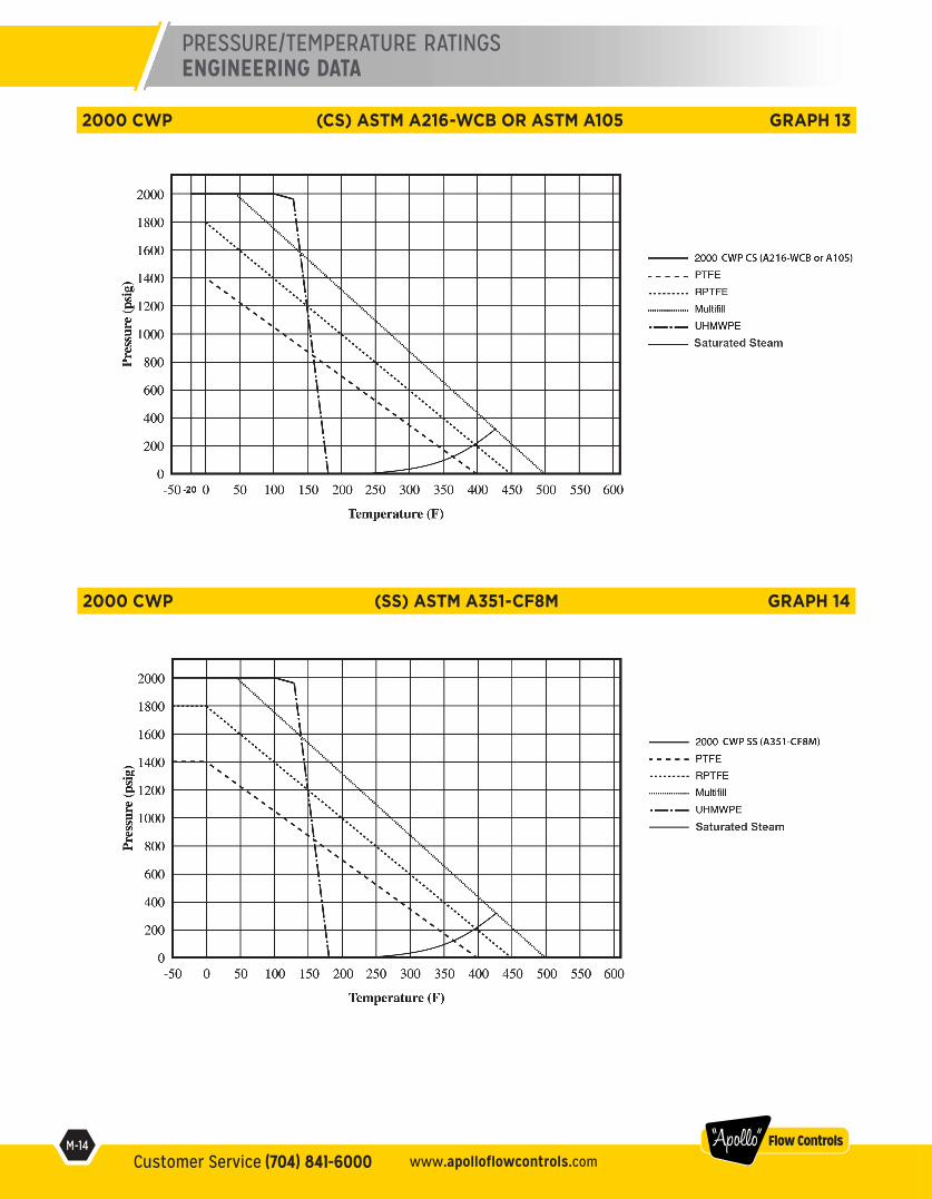
2000 CWP (SS) ASTM A351-CF8M GRAPH 14
2000 CWP (CS) ASTM A216-WCB OR ASTM A105 GRAPH 13
PRESSURE/TEMPERATURE RATINGSENGINEERING DATA

M-13Customer Service (704) 841-6000industrial.apollovalves.com
“Apollo” Flow Controls
1500 CWP (SS) ASTM A351-CF8M GRAPH 12
1500 CWP (CS) ASTM A216-WCB OR ASTM A105 GRAPH 11
PRESSURE/TEMPERATURE RATINGSENGINEERING DATA
M-12Customer Service (704) 841-6000 www.apolloflowcontrols.com
“Apollo” Flow Controls
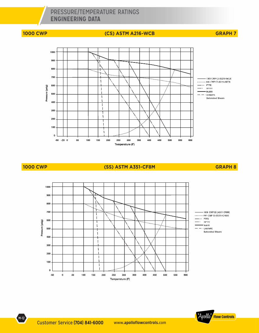
1000 CWP (SS) ASTM A351-CF8M GRAPH 8
1000 CWP (CS) ASTM A216-WCB GRAPH 7
PRESSURE/TEMPERATURE RATINGSENGINEERING DATA