
75/80/90/100/115 EFI FourStroke -...
149
eng i Thank You for your purchase of one of the finest outboards available. You have made a sound investment in boating pleasure. Your outboard has been manufactured by Mercury Marine, a world leader in marine technology and outboard manufacturing since 1939. These years of experience have been committed to the goal of producing the finest quality products. This led to Mercury Marine's reputation for strict quality control, excellence, durability, lasting performance, and being the best at providing after the sale support. Please read this manual carefully before operating your outboard. This manual has been prepared to assist you in the operation, safe use, and care of your outboard. All of us at Mercury Marine took pride in building your outboard and wish you many years of happy and safe boating. Again, thank you for your confidence in Mercury Marine. EPA Emissions Regulations Outboards sold by Mercury Marine in the United States are certified to the United States Environmental Protection Agency as conforming to the requirements of the regulations for the control of air pollution from new outboard motors. This certification is contingent on certain adjustments being set to factory standards. For this reason, the factory procedure for servicing the product must be strictly followed and, wherever practicable, returned to the original intent of the design. Maintenance, replacement, or repair of the emission control devices and systems may be performed by any marine engine repair establishment or individual. Engines are labeled with an Emission Control Information decal as permanent evidence of EPA certification. ! WARNING The engine exhaust from this product contains chemicals known to the state of California to cause cancer, birth defects or other reproductive harm. © 2012 Mercury Marine 75/80/90/100/115 EFI FourStroke 90-8M0055679 311
Transcript of 75/80/90/100/115 EFI FourStroke -...
eng i
Thank Youfor your purchase of one of the finest outboards available.You have made a sound investment in boating pleasure.Your outboard has been manufactured by Mercury Marine, aworld leader in marine technology and outboardmanufacturing since 1939. These years of experience havebeen committed to the goal of producing the finest qualityproducts. This led to Mercury Marine's reputation for strictquality control, excellence, durability, lasting performance,and being the best at providing after the sale support.Please read this manual carefully before operating youroutboard. This manual has been prepared to assist you inthe operation, safe use, and care of your outboard.All of us at Mercury Marine took pride in building youroutboard and wish you many years of happy and safeboating.Again, thank you for your confidence in Mercury Marine.
EPA Emissions RegulationsOutboards sold by Mercury Marine in the United States arecertified to the United States Environmental ProtectionAgency as conforming to the requirements of the regulationsfor the control of air pollution from new outboard motors.This certification is contingent on certain adjustments beingset to factory standards. For this reason, the factoryprocedure for servicing the product must be strictly followedand, wherever practicable, returned to the original intent ofthe design. Maintenance, replacement, or repair of theemission control devices and systems may beperformed by any marine engine repair establishment orindividual.Engines are labeled with an Emission Control Informationdecal as permanent evidence of EPA certification.
! WARNINGThe engine exhaust from this product contains chemicalsknown to the state of California to cause cancer, birthdefects or other reproductive harm.
© 2
012
Mer
cury
Mar
ine
75/8
0/90
/100
/115
EFI
Fou
rStro
ke90
-8M
0055
679
311
ii eng
Warranty MessageThe product you have purchased comes with a limited warrantyfrom Mercury Marine, the terms of the warranty are set forth inthe Warranty Information section of this manual. The warrantystatement contains a description of what is covered, what is notcovered, the duration of coverage, how to best obtain warrantycoverage, important disclaimers and limitations of damages,and other related information. Please review this importantinformation.The description and specifications contained herein were ineffect at the time this manual was approved for printing. MercuryMarine, whose policy is one of continued improvement, reservesthe right to discontinue models at any time, to changespecifications, designs, methods, or procedures without noticeand without incurring obligation.Mercury Marine, Fond du Lac, Wisconsin U.S.A.Litho in U.S.A.© 2011, Mercury MarineMercury, Mercury Marine, MerCruiser, Mercury MerCruiser,Mercury Racing, Mercury Precision Parts, Mercury Propellers,Mariner, Quicksilver, #1 On The Water, Alpha, Bravo, Pro Max,OptiMax, Sport‑Jet, K‑Planes, MerCathode, RideGuide,SmartCraft, Zero Effort, M with Waves logo, Mercury with Waveslogo, and SmartCraft logo are all registered trademarks ofBrunswick Corporation. Mercury Product Protection logo is aregistered service mark of Brunswick Corporation.
Mercury Premier ServiceMercury evaluates the service performance of its dealers andassigns its highest rating of "Mercury Premier" to thosedemonstrating an exceptional commitment to service.Earning a Mercury Premier Service rating means a dealer:• Achieves a high 12 month service CSI (Customer
Satisfaction Index) score for warranty service.• Possesses all necessary service tools, test equipment,
manuals, and parts books.• Employs at least one Certified or Master technician.
eng iii
• Provides timely service for all Mercury Marine customers.• Offers extended service hours and mobile service, when
appropriate.• Uses, displays, and stocks adequate inventory of genuine
Mercury Precision Parts.• Offers a clean, neat shop with well organized tools and
service literature.
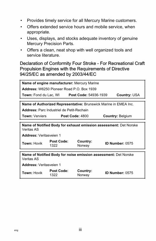
Declaration of Conformity Four Stroke ‑ For Recreational CraftPropulsion Engines with the Requirements of Directive94/25/EC as amended by 2003/44/EC
Name of engine manufacturer: Mercury MarineAddress: W6250 Pioneer Road P.O. Box 1939Town: Fond du Lac, WI Post Code: 54936‑1939 Country: USA
Name of Authorized Representative: Brunswick Marine in EMEA Inc.Address: Parc Industriel de Petit‑RechainTown: Verviers Post Code: 4800 Country: Belgium
Name of Notified Body for exhaust emission assessment: Det NorskeVeritas ASAddress: Veritasveien 1
Town: Hovik Post Code:1322
Country:Norway ID Number: 0575
Name of Notified Body for noise emission assessment: Det NorskeVeritas ASAddress: Veritasveien 1
Town: Hovik Post Code:1322
Country:Norway ID Number: 0575
iv eng
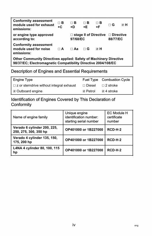
Conformity assessmentmodule used for exhaustemissions:
☐ B+C
☐ B+D
☐ B+E
☐ B+F ☐ G ☒ H
or engine type approvedaccording to:
☐ stage II of Directive97/68/EC
☐ Directive88/77/EC
Conformity assessmentmodule used for noiseemissions:
☐ A ☐ Aa ☐ G ☒ H
Other Community Directives applied: Safety of Machinery Directive98/37/EC; Electromagnetic Compatibility Directive 2004/108/EC
Description of Engines and Essential Requirements
Engine Type Fuel Type Combustion Cycle☐ z or sterndrive without integral exhaust ☐ Diesel ☐ 2 stroke☒ Outboard engine ☒ Petrol ☒ 4 stroke
Identification of Engines Covered by This Declaration ofConformity
Name of engine familyUnique engineidentification number:starting serial number
EC Module Hcertificatenumber
Verado 6 cylinder 200, 225,250, 275, 300, 350 hp OP401000 or 1B227000 RCD‑H‑2
Verado 4 cylinder 135, 150,175, 200 hp OP401000 or 1B227000 RCD‑H‑2
L4NA 4 cylinder 80, 100, 115hp OP401000 or 1B227000 RCD‑H‑2
eng v
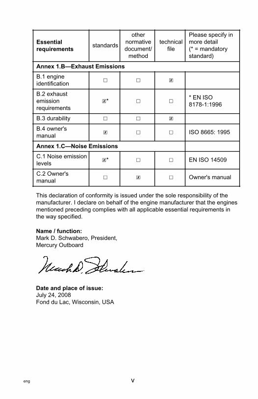
Essentialrequirements standards
othernormativedocument/
method
technicalfile
Please specify inmore detail(* = mandatorystandard)
Annex 1.B—Exhaust EmissionsB.1 engineidentification ☐ ☐ ☒
B.2 exhaustemissionrequirements
☒* ☐ ☐ * EN ISO8178‑1:1996
B.3 durability ☐ ☐ ☒
B.4 owner'smanual ☒ ☐ ☐ ISO 8665: 1995
Annex 1.C—Noise EmissionsC.1 Noise emissionlevels ☒* ☐ ☐ EN ISO 14509
C.2 Owner'smanual ☐ ☒ ☐ Owner's manual
This declaration of conformity is issued under the sole responsibility of themanufacturer. I declare on behalf of the engine manufacturer that the enginesmentioned preceding complies with all applicable essential requirements inthe way specified.
Name / function:Mark D. Schwabero, President,Mercury Outboard
Date and place of issue:July 24, 2008Fond du Lac, Wisconsin, USA

vi eng
eng vii
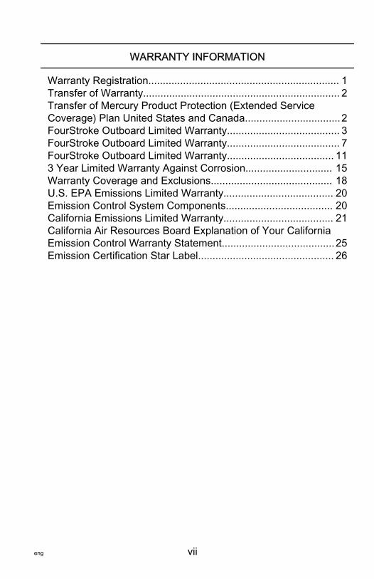
WARRANTY INFORMATION
Warranty Registration.................................................................. 1Transfer of Warranty.................................................................... 2Transfer of Mercury Product Protection (Extended ServiceCoverage) Plan United States and Canada.................................2FourStroke Outboard Limited Warranty....................................... 3FourStroke Outboard Limited Warranty....................................... 7FourStroke Outboard Limited Warranty..................................... 113 Year Limited Warranty Against Corrosion.............................. 15Warranty Coverage and Exclusions.......................................... 18U.S. EPA Emissions Limited Warranty...................................... 20Emission Control System Components..................................... 20California Emissions Limited Warranty...................................... 21California Air Resources Board Explanation of Your CaliforniaEmission Control Warranty Statement.......................................25Emission Certification Star Label............................................... 26
viii eng
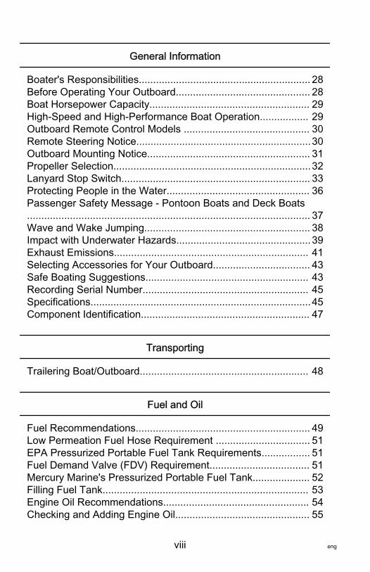
General Information
Boater's Responsibilities............................................................ 28Before Operating Your Outboard............................................... 28Boat Horsepower Capacity........................................................ 29High‑Speed and High‑Performance Boat Operation................. 29Outboard Remote Control Models ............................................ 30Remote Steering Notice.............................................................30Outboard Mounting Notice......................................................... 31Propeller Selection.....................................................................32Lanyard Stop Switch.................................................................. 33Protecting People in the Water.................................................. 36Passenger Safety Message ‑ Pontoon Boats and Deck Boats................................................................................................... 37Wave and Wake Jumping.......................................................... 38Impact with Underwater Hazards...............................................39Exhaust Emissions.................................................................... 41Selecting Accessories for Your Outboard.................................. 43Safe Boating Suggestions......................................................... 43Recording Serial Number.......................................................... 45Specifications.............................................................................45Component Identification........................................................... 47
Transporting
Trailering Boat/Outboard........................................................... 48
Fuel and Oil
Fuel Recommendations............................................................. 49Low Permeation Fuel Hose Requirement ................................. 51EPA Pressurized Portable Fuel Tank Requirements................. 51Fuel Demand Valve (FDV) Requirement................................... 51Mercury Marine's Pressurized Portable Fuel Tank.................... 52Filling Fuel Tank........................................................................ 53Engine Oil Recommendations................................................... 54Checking and Adding Engine Oil............................................... 55
eng ix
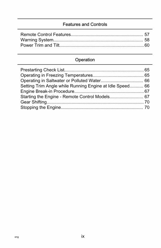
Features and Controls
Remote Control Features.......................................................... 57Warning System........................................................................ 58Power Trim and Tilt....................................................................60
Operation
Prestarting Check List................................................................65Operating in Freezing Temperatures......................................... 65Operating in Saltwater or Polluted Water.................................. 66Setting Trim Angle while Running Engine at Idle Speed........... 66Engine Break‑in Procedure........................................................67Starting the Engine ‑ Remote Control Models........................... 67Gear Shifting.............................................................................. 70Stopping the Engine.................................................................. 70
x eng
Maintenance
Outboard Care........................................................................... 71EPA Emissions Regulations...................................................... 71Inspection and Maintenance Schedule...................................... 72Flushing the Cooling System..................................................... 75Top Cowl Removal and Installation........................................... 77Flywheel Cover Removal and Installation..................................78Cleaning Care for Top and Bottom Cowls................................. 78Cleaning Care for the Powerhead (Saltwater Use)....................79Battery Inspection ..................................................................... 79Air Filter..................................................................................... 80Fuel System............................................................................... 81Corrosion Control Anode........................................................... 85Propeller Replacement.............................................................. 86Spark Plug Inspection and Replacement...................................90Fuse Replacement.....................................................................92Alternator Drive Belt Inspection................................................. 94Lubrication Points...................................................................... 94Checking Power Trim Fluid........................................................97Changing Engine Oil ................................................................. 97Gearcase Lubrication.................................................................99
Storage
Storage Preparation.................................................................102Protecting External Outboard Components............................. 103Protecting Internal Engine Components.................................. 103Gearcase................................................................................. 103Positioning Outboard for Storage............................................ 104Battery Storage........................................................................ 104
eng xi
Troubleshooting
Starter Motor Will Not Crank the Engine..................................105Engine Will Not Start................................................................105Engine Runs Erratically........................................................... 105Performance Loss....................................................................106Battery Will Not Hold Charge................................................... 106
Owner Service Assistance
Local Repair Service................................................................107Service Away from Home........................................................ 107Parts and Accessories Inquiries.............................................. 107Service Assistance.................................................................. 107Mercury Marine Service Offices...............................................108
Outboard Installation
Important Information...............................................................110Boat Horsepower Capacity...................................................... 110Start in Gear Protection........................................................... 111Selecting Accessories for Your Outboard................................ 111Fuel System............................................................................. 111Installation Specifications........................................................ 113Lifting Outboard....................................................................... 114Steering Cable ‑ Starboard Side Routed Cable....................... 115Steering Link Rod Fasteners................................................... 116Determining Recommended Outboard Mounting Height......... 118Drilling Outboard Mounting Holes............................................ 119Fastening the Outboard to the Transom.................................. 120Electrical, Fuel Hose, and Control Cables............................... 124Trim In Pin............................................................................... 135
Maintenance Log
Maintenance Log..................................................................... 137

xii eng
WARRANTY INFORMATION
eng 1
Warranty RegistrationUNITED STATES AND CANADATo be eligible for warranty coverage, the product must beregistered with Mercury Marine.At the time of sale, the selling dealer should complete thewarranty registration and immediately submit it to MercuryMarine via MercNET, e‑mail, or mail. Upon receipt of thiswarranty registration, Mercury Marine will record the registration.A copy of the warranty registration should be provided to you byyour selling dealer.NOTE: Registration lists must be maintained by Mercury Marineand any dealer on marine products sold in the United States,should a safety recall notification under the Federal Safety Actbe required.You may change your address at any time, including at time ofwarranty claim, by calling Mercury Marine or sending a letter orfax with your name, old address, new address, and engine serialnumber to Mercury Marine’s warranty registration department.Your dealer can also process this change of information.Mercury MarineAttn: Warranty Registration DepartmentW6250 W. Pioneer RoadP.O. Box 1939Fond du Lac, WI 54936-1939920-929-5054Fax +1 920 929 5893
OUTSIDE UNITED STATES AND CANADAFor products purchased outside the United States and Canada,contact the distributor in your country, or the Marine PowerService Center closest to you.
WARRANTY INFORMATION
2 eng
Transfer of WarrantyUNITED STATES AND CANADAThe limited warranty is transferable to a subsequent purchaser,but only for the remainder of the unused portion of the limitedwarranty. This will not apply to products used for commercialapplications.To transfer the warranty to the subsequent owner, send or fax acopy of the bill of sale or purchase agreement, new owner’sname, address, and engine serial number to Mercury Marine’swarranty registration department. In the United States andCanada, mail to:Mercury MarineAttn: Warranty Registration DepartmentW6250 W. Pioneer RoadP.O. Box 1939Fond du Lac, WI 54936-1939920-929-5054Fax +1 920 929 5893Upon processing the transfer of warranty, Mercury Marine willrecord the new owner's information.There is no charge for this service.
OUTSIDE THE UNITED STATES AND CANADAFor products purchased outside the United States and Canada,contact the distributor in your country, or the Marine PowerService Center closest to you.
Transfer of Mercury Product Protection (ExtendedService Coverage) Plan United States and CanadaThe remaining coverage period of the Product Protection Plan istransferable to the subsequent purchaser of the engine withinthirty (30) days from the date of sale. Contracts not transferredwithin thirty (30) days of the subsequent purchase will no longerbe valid and the product will no longer be eligible for coverageunder the terms of the contract.
WARRANTY INFORMATION
eng 3
To transfer the plan to the subsequent owner, contact MercuryProduct Protection or an authorized dealer to receive a Requestfor Transfer form. Submit to Mercury Product Protection areceipt/bill of sale, a completed Request of Transfer form, and acheck payable to Mercury Marine in the amount of $50.00 (perengine) to cover the transfer fee.Plan coverage is not transferable from one product to anotherproduct or for non‑eligible applications.The Certified Pre‑Owned engine plans are not transferable.For help or assistance, contact Mercury Product ProtectionDepartment at 1‑888‑427‑5373 from 7:30 a.m. to 4:30 p.m. CST,Monday–Friday or email [email protected].
FourStroke Outboard Limited WarrantyUNITED STATES AND CANADAOutside the United States and Canada ‑ Check with your localdistributor.WHAT IS COVERED: Mercury Marine warrants its new productsto be free of defects in material and workmanship during theperiod described below.
WARRANTY INFORMATION
4 eng
DURATION OF COVERAGE: This Limited Warranty providescoverage for three (3) years from the date the product is first soldto a recreational use retail purchaser, or the date on which theproduct is first put into service, whichever occurs first.Commercial users of these products receive warranty coverageof one (1) year from the date of first retail sale, or one (1) yearfrom the date on which the product was first put into service,whichever occurs first. Commercial use is defined as any work oremployment related use of the product, or any use of the productwhich generates income, for any part of the warranty period,even if the product is only occasionally used for such purposes.The repair or replacement of parts, or the performance of serviceunder this warranty, does not extend the life of this warrantybeyond its original expiration date. Unexpired warranty coveragecan be transferred from one recreational use customer to asubsequent recreational use customer upon proper reregistrationof the product. Unexpired warranty coverage cannot betransferred either to or from a commercial use customer.Warranty coverage may be terminated for used repossessedproduct; or product purchased at auction, from a salvage yard, orfrom an insurance company.CONDITIONS THAT MUST BE MET IN ORDER TO OBTAINWARRANTY COVERAGE: Warranty coverage is available onlyto retail customers that purchase from a Dealer authorized byMercury Marine to distribute the product in the country in whichthe sale occurred, and then only after the Mercury Marinespecified predelivery inspection process is completed anddocumented. Warranty coverage becomes available upon properregistration of the product by the authorized dealer. Inaccuratewarranty registration information regarding recreational use, orsubsequent change of use from recreational to commercial(unless properly reregistered) may void the warranty at the solediscretion of Mercury Marine. Routine maintenance outlined inthe Operation and Maintenance Manual must be timelyperformed in order to maintain warranty coverage. MercuryMarine reserves the right to make warranty coverage contingentupon proof of proper maintenance.

WARRANTY INFORMATION
eng 5
WHAT MERCURY WILL DO: Mercury's sole and exclusiveobligation under this warranty is limited to, at our option,repairing a defective part, replacing such part or parts with newor Mercury Marine certified remanufactured parts, or refundingthe purchase price of the Mercury product. Mercury reserves theright to improve or modify products from time to time withoutassuming an obligation to modify products previouslymanufactured.HOW TO OBTAIN WARRANTY COVERAGE: The customermust provide Mercury with a reasonable opportunity to repair,and reasonable access to the product for warranty service.Warranty claims shall be made by delivering the product forinspection to a Mercury dealer authorized to service the product.If purchaser cannot deliver the product to such a dealer, writtennotice must be given to Mercury. We will then arrange for theinspection and any covered repair. Purchaser, in that case, shallpay for all related transportation charges and/or travel time. If theservice provided is not covered by this warranty, purchaser shallpay for all related labor and material, and any other expensesassociated with that service. Purchaser shall not, unlessrequested by Mercury, ship the product or parts of the productdirectly to Mercury. Proof of registered ownership must bepresented to the dealer at the time warranty service is requestedin order to obtain coverage.
WARRANTY INFORMATION
6 eng
WHAT IS NOT COVERED: This limited warranty does not coverroutine maintenance items, tune‑ups, adjustments, normal wearand tear, damage caused by abuse, abnormal use, use of apropeller or gear ratio that does not allow the engine to run in itsrecommended wide‑open throttle RPM range (see the Operationand Maintenance Manual), operation of the product in a mannerinconsistent with the recommended operation/duty cycle sectionof the Operation and Maintenance Manual, neglect, accident,submersion, improper installation (proper installationspecifications and techniques are set forth in the installationinstructions for the product), improper service, use of anaccessory or part not manufactured or sold by us, jet pumpimpellers and liners, operation with fuels, oils, or lubricants whichare not suitable for use with the product (see the Operation andMaintenance Manual), alteration or removal of parts, waterentering the engine through the fuel intake, air intake or exhaustsystem, or damage to the product from insufficient cooling watercaused by blockage of the cooling system by a foreign body,running the engine out of water, mounting the engine too high onthe transom, or running the boat with the engine trimmed out toofar. Use of the product for racing or other competitive activity, oroperating with a racing type lower unit, at any point, even by aprior owner of the product, voids the warranty.Expenses related to haul‑out, launch, towing, storage, telephone,rental, inconvenience, slip fees, insurance coverage, loanpayments, loss of time, loss of income, or any other type ofincidental or consequential damages are not covered by thiswarranty. Also, expenses associated with the removal and/orreplacement of boat partitions or material caused by boat designfor access to the product are not covered by this warranty.No individual or entity, including Mercury Marine authorizeddealers, has been given authority by Mercury Marine to makeany affirmation, representation, or warranty regarding theproduct, other than those contained in this limited warranty, andif made, shall not be enforceable against Mercury Marine.
WARRANTY INFORMATION
eng 7
For additional information regarding events and circumstancescovered by this warranty, and those that are not, see theWarranty Coverage section of the Operation and MaintenanceManual, incorporated by reference into this warranty.
DISCLAIMERS AND LIMITATIONS:
THE IMPLIED WARRANTIES OF MERCHANTABILITY AND FITNESS FORA PARTICULAR PURPOSE ARE EXPRESSLY DISCLAIMED. TO THEEXTENT THAT THEY CANNOT BE DISCLAIMED, THE IMPLIEDWARRANTIES ARE LIMITED IN DURATION TO THE LIFE OF THEEXPRESS WARRANTY. INCIDENTAL AND CONSEQUENTIAL DAMAGESARE EXCLUDED FROM COVERAGE UNDER THIS WARRANTY. SOMESTATES/COUNTRIES DO NOT ALLOW FOR THE DISCLAIMERS,LIMITATIONS AND EXCLUSIONS IDENTIFIED ABOVE, AS A RESULT,THEY MAY NOT APPLY TO YOU. THIS WARRANTY GIVES YOUSPECIFIC LEGAL RIGHTS, AND YOU MAY ALSO HAVE OTHER LEGALRIGHTS WHICH VARY FROM STATE TO STATE AND COUNTRY TOCOUNTRY.
FourStroke Outboard Limited WarrantyEUROPE AND CONFEDERATION OF INDEPENDENTSTATESOutside Europe and Confederation of Independent States ‑check with local distributor.WHAT IS COVERED: Mercury Marine warrants its new productsto be free of defects in material and workmanship during theperiod described below.
WARRANTY INFORMATION
8 eng
DURATION OF COVERAGE: This Limited Warranty providescoverage for two (2) years from the date the product is first soldto a recreational use retail purchaser, or the date on which theproduct is first put into service, whichever occurs first.Commercial users of these products receive warranty coverageof one (1) year from the date of first retail sale, or one (1) yearfrom the date in which the product was first put into service,whichever occurs first. Commercial use is defined as any work oremployment related use of the product, or any use of the productwhich generates income, for any part of the warranty period,even if the product is only occasionally used for such purposes.The repair or replacement of parts, or the performance of serviceunder this warranty, does not extend the life of this warrantybeyond its original expiration date. Unexpired warranty coveragecan be transferred from one recreational use customer to asubsequent recreational use customer upon proper reregistrationof the product. Unexpired warranty coverage cannot betransferred either to or from a commercial use customer.Warranty coverage may be terminated for used or repossessedproduct; or product purchased at auction, from a salvage yard, orfrom an insurance company.CONDITIONS THAT MUST BE MET IN ORDER TO OBTAINWARRANTY COVERAGE: Warranty coverage is available onlyto retail customers that purchase from a Dealer authorized byMercury Marine to distribute the product in the country in whichthe sale occurred, and then only after the Mercury Marinespecified predelivery inspection process is completed anddocumented. Warranty coverage becomes available upon properregistration of the product by the authorized dealer. Routinemaintenance outlined in the Operation and Maintenance Manualmust be timely performed in order to maintain warrantycoverage. Mercury Marine reserves the right to make futurewarranty coverage contingent on proof of proper maintenance.
WARRANTY INFORMATION
eng 9
WHAT MERCURY WILL DO: Mercury’s sole and exclusiveobligation under this warranty is limited to, at our option,repairing a defective part, replacing such part or parts with newor Mercury Marine certified remanufactured parts, or refundingthe purchase price of the Mercury product. Mercury reserves theright to improve or modify products from time to time withoutassuming an obligation to modify products previouslymanufactured.HOW TO OBTAIN WARRANTY COVERAGE: The customermust provide Mercury with a reasonable opportunity to repair,and reasonable access to the product for warranty service.Warranty claims shall be made by delivering the product forinspection to a Mercury dealer authorized to service the product.If purchaser cannot deliver the product to such a dealer, writtennotice must be given to Mercury. We will then arrange for theinspection and any covered repair. Purchaser in that case shallpay for all related transportation charges and/or travel time. If theservice provided is not covered by this warranty, purchaser shallpay for all related labor and material, and any other expensesassociated with that service. Purchaser shall not, unlessrequested by Mercury, ship the product or parts of the productdirectly to Mercury. Proof of registered ownership must bepresented to the dealer at the time warranty service is requestedin order to obtain coverage.
WARRANTY INFORMATION
10 eng
WHAT IS NOT COVERED: This limited warranty does not coverroutine maintenance items, tune‑ups, adjustments, normal wearand tear, damage caused by abuse, abnormal use, use of apropeller or gear ratio that does not allow the engine to run in itsrecommended wide‑open throttle RPM range (see the Operationand Maintenance Manual), operation of the product in a mannerinconsistent with the recommended operation/duty cycle sectionof the Operation and Maintenance Manual, neglect, accident,submersion, improper installation (proper installationspecifications and techniques are set forth in the installationinstructions for the product), improper service, use of anaccessory or part not manufactured or sold by us, jet pumpimpellers and liners, operation with fuels, oils or lubricants whichare not suitable for use with the product (see the Operation andMaintenance Manual), alteration or removal of parts, or waterentering the engine through the fuel intake, air intake or exhaustsystem, or damage to the product from insufficient cooling watercaused by blockage of the cooling system by a foreign body,running the engine out of water, mounting the engine too high onthe transom, or running the boat with the engine trimmed out toofar. Use of the product for racing or other competitive activity, oroperating with a racing type lower unit, at any point, even by aprior owner of the product, voids the warranty.Expenses related to haul out, launch, towing, storage, telephone,rental, inconvenience, slip fees, insurance coverage, loanpayments, loss of time, loss of income, or any other type ofincidental or consequential damages are not covered by thiswarranty. Also, expenses associated with the removal and/orreplacement of boat partitions or material caused by boat designfor access to the product are not covered by this warranty.No individual or entity, including Mercury Marine authorizeddealers, has been given authority by Mercury Marine to makeany affirmation, representation or warranty regarding theproduct, other than those contained in this limited warranty, andif made, shall not be enforceable against Mercury Marine.
WARRANTY INFORMATION
eng 11
For additional information regarding events and circumstancescovered by this warranty, and those that are not, see theWarranty Coverage section of the Operation and MaintenanceManual, incorporated by reference into this warranty.
DISCLAIMERS AND LIMITATIONS:
THE IMPLIED WARRANTIES OF MERCHANTABILITY AND FITNESS FORA PARTICULAR PURPOSE ARE EXPRESSLY DISCLAIMED. TO THEEXTENT THAT THEY CANNOT BE DISCLAIMED, THE IMPLIEDWARRANTIES ARE LIMITED IN DURATION TO THE LIFE OF THEEXPRESS WARRANTY. INCIDENTAL AND CONSEQUENTIAL DAMAGESARE EXCLUDED FROM COVERAGE UNDER THIS WARRANTY. SOMESTATES/COUNTRIES DO NOT ALLOW FOR THE DISCLAIMERS,LIMITATIONS AND EXCLUSIONS IDENTIFIED ABOVE, AS A RESULT,THEY MAY NOT APPLY TO YOU. THIS WARRANTY GIVES YOUSPECIFIC LEGAL RIGHTS, AND YOU MAY ALSO HAVE OTHER LEGALRIGHTS WHICH VARY FROM STATE TO STATE AND COUNTRY TOCOUNTRY.
FourStroke Outboard Limited WarrantyMIDDLE-EAST AND AFRICAWHAT IS COVERED: Mercury Marine warrants its newOutboard and Jet Products to be free of defects in material andworkmanship during the period described below.
WARRANTY INFORMATION
12 eng
DURATION OF COVERAGE: This Limited Warranty providescoverage for one (1) year from the date the product is first sold toa recreational use retail purchaser, or the date on which theproduct is first put into service, whichever occurs first.Commercial users of these products receive warranty coverageof one (1) years from the date of first retail sale, or one (1) yearfrom the date on which the product was first put into service,whichever occurs first. Commercial use is defined as any work oremployment related use of the product, or any use of the productwhich generates income, for any part of the warranty period,even if the product is only occasionally used for such purposes.The repair or replacement of parts, or the performance of serviceunder this warranty, does not extend the life of this warrantybeyond its original expiration date. Unexpired warranty coveragecan be transferred from one recreational use customer to asubsequent recreational use customer upon proper reregistrationof the product. Unexpired warranty coverage cannot betransferred either to or from a commercial use customer.CONDITIONS THAT MUST BE MET IN ORDER TO OBTAINWARRANTY COVERAGE: Warranty coverage is available onlyto retail customers that purchase from a Dealer authorized byMercury Marine to distribute the product in the country in whichthe sale occurred, and then only after the Mercury Marinespecified predelivery inspection process is completed anddocumented. Warranty coverage becomes available upon properregistration of the product by the authorized dealer. Routinemaintenance outlined in the Operation and Maintenance Manualmust be timely performed in order to maintain warrantycoverage. Mercury Marine reserves the right to make warrantycoverage contingent on proof of proper maintenance.WHAT MERCURY WILL DO: Mercury’s sole and exclusiveobligation under this warranty is limited to, at our option,repairing a defective part, replacing such part or parts with newor Mercury Marine certified remanufactured parts, or refundingthe purchase price of the Mercury product. Mercury reserves theright to improve or modify products from time to time withoutassuming an obligation to modify products previouslymanufactured.
WARRANTY INFORMATION
eng 13
HOW TO OBTAIN WARRANTY COVERAGE: The customermust provide Mercury with a reasonable opportunity to repair,and reasonable access to the product for warranty service.Warranty claims shall be made by delivering the product forinspection to a Mercury dealer authorized to service the product.If purchaser cannot deliver the product to such a dealer, writtennotice must be given to Mercury. We will then arrange for theinspection and any covered repair. Purchaser in that case shallpay for all related transportation charges and/or travel time. If theservice provided is not covered by this warranty, purchaser shallpay for all related labor and material, and any other expensesassociated with that service. Purchaser shall not, unlessrequested by Mercury, ship the product or parts of the productdirectly to Mercury. Proof of registered ownership must bepresented to the dealer at the time warranty service is requestedin order to obtain coverage.WHAT IS NOT COVERED: This limited warranty does not coverroutine maintenance items, tune‑ups, adjustments, normal wearand tear, damage caused by abuse, abnormal use, use of apropeller or gear ratio that does not allow the engine to run in itsrecommended wide‑open throttle RPM range (see the Operationand Maintenance Manual), operation of the product in a mannerinconsistent with the recommended operation/duty cycle sectionof the Operation and Maintenance Manual, neglect, accident,submersion, improper installation (proper installationspecifications and techniques are set forth in the installationinstructions for the product), improper service, use of anaccessory or part not manufactured or sold by us, jet pumpimpellers and liners, operation with fuels, oils or lubricants whichare not suitable for use with the product (see the Operation andMaintenance Manual), alteration or removal of parts, or waterentering the engine through the fuel intake, air intake or exhaustsystem, or damage to the product from insufficient cooling watercaused by blockage of the cooling system by foreign body,running the engine out of water, mounting the engine too high onthe transom, or running the boat with the engine trimmed out toofar.
WARRANTY INFORMATION
14 eng
Use of the product for racing or other competitive activity, oroperating with a racing type lower unit, at any point, even by aprior owner of the product, voids the warranty.Expenses related to haul out, launch, towing, storage, telephone,rental, inconvenience, slip fees, insurance coverage, loanpayments, loss of time, loss of income, or any other type ofincidental or consequential damages are not covered by thiswarranty. Also, expenses associated with the removal and/orreplacement of boat partitions or material caused by boat designfor access to the product are not covered by this warranty.No individual or entity, including Mercury Marine authorizeddealers, has been given authority by Mercury Marine to makeany affirmation, representation or warranty regarding theproduct, other than those contained in this limited warranty, andif made, shall not be enforceable against Mercury Marine.For additional information regarding events and circumstancescovered by this warranty, and those that are not, see theWarranty Coverage section of the Operation and MaintenanceManual, incorporated by reference into this warranty.
DISCLAIMERS AND LIMITATIONS:
THE IMPLIED WARRANTIES OF MERCHANTABILITY AND FITNESS FORA PARTICULAR PURPOSE ARE EXPRESSLY DISCLAIMED. TO THEEXTENT THAT THEY CANNOT BE DISCLAIMED, THE IMPLIEDWARRANTIES ARE LIMITED IN DURATION TO THE LIFE OF THEEXPRESS WARRANTY. INCIDENTAL AND CONSEQUENTIAL DAMAGESARE EXCLUDED FROM COVERAGE UNDER THIS WARRANTY. SOMESTATES/COUNTRIES DO NOT ALLOW FOR THE DISCLAIMERS,LIMITATIONS AND EXCLUSIONS IDENTIFIED ABOVE, AS A RESULT,THEY MAY NOT APPLY TO YOU. THIS WARRANTY GIVES YOUSPECIFIC LEGAL RIGHTS, AND YOU MAY ALSO HAVE OTHER LEGALRIGHTS WHICH VARY FROM STATE TO STATE AND COUNTRY TOCOUNTRY.
WARRANTY INFORMATION
eng 15
3 Year Limited Warranty Against CorrosionWHAT IS COVERED: Mercury Marine warrants that each newMercury, Mariner, Mercury Racing, Sport Jet, M2 Jet Drive,Tracker by Mercury Marine Outboard, Mercury MerCruiserInboard or Sterndrive Engine (Product) will not be renderedinoperative as a direct result of corrosion for the period of timedescribed below.DURATION OF COVERAGE: This limited corrosion warrantyprovides coverage for three (3) years from either the date theproduct is first sold, or the date on which the product is first putinto service, whichever occurs first. The repair or replacement ofparts, or the performance of service under this warranty, doesnot extend the life of this warranty beyond its original expirationdate. Unexpired warranty coverage can be transferred tosubsequent (noncommercial use) purchaser upon properreregistration of the product.CONDITIONS THAT MUST BE MET IN ORDER TO OBTAINWARRANTY COVERAGE: Warranty coverage is available onlyto retail customers that purchase from a Dealer authorized byMercury Marine to distribute the product in the country in whichthe sale occurred, and then only after the Mercury Marinespecified predelivery inspection process is completed anddocumented. Warranty coverage becomes available upon properregistration of the product by the authorized dealer. Corrosionprevention devices specified in the Operation and MaintenanceManual must be in use on the boat, and routine maintenanceoutlined in the Operation and Maintenance Manual must betimely performed (including, without limitation, the replacement ofsacrificial anodes, use of specified lubricants, and touch‑up ofnicks and scratches) in order to maintain warranty coverage.Mercury Marine reserves the right to make warranty coveragecontingent upon proof of proper maintenance.
WARRANTY INFORMATION
16 eng
WHAT MERCURY WILL DO: Mercury's sole and exclusiveobligation under this warranty is limited to, at our option,repairing a corroded part, replacing such part or parts with newor Mercury Marine certified remanufactured parts, or refundingthe purchase price of the Mercury product. Mercury reserves theright to improve or modify products from time to time withoutassuming an obligation to modify products previouslymanufactured.HOW TO OBTAIN WARRANTY COVERAGE: The customermust provide Mercury with a reasonable opportunity to repair,and reasonable access to the product for warranty service.Warranty claims shall be made by delivering the product forinspection to a Mercury dealer authorized to service the product.If purchaser cannot deliver the product to such a dealer, writtennotice must be given to Mercury. We will then arrange for theinspection and any covered repair. Purchaser, in that case, shallpay for all related transportation charges and/or travel time. If theservice provided is not covered by this warranty, purchaser shallpay for all related labor and material, and any other expensesassociated with that service. Purchaser shall not, unlessrequested by Mercury, ship the product or parts of the productdirectly to Mercury. Proof of registered ownership must bepresented to the dealer at the time warranty service is requestedin order to obtain coverage.WHAT IS NOT COVERED: This limited warranty does not coverelectrical system corrosion; corrosion resulting from damage,corrosion which causes purely cosmetic damage, abuse, orimproper service; corrosion to accessories, instruments, steeringsystems; corrosion to factory installed jet drive unit; damage dueto marine growth; product sold with less than a one year limitedProduct warranty; replacement parts (parts purchased bycustomer); products used in a commercial application.Commercial use is defined as any work or employment relateduse of the product, or any use of the product which generatesincome, for any part of the warranty period, even if the product isonly occasionally used for such purposes.
WARRANTY INFORMATION
eng 17
Corrosion damage caused by stray electrical currents (onshorepower connections, nearby boats, submerged metal) is notcovered by this corrosion warranty and should be protectedagainst by the use of a corrosion protection system, such as theMercury Precision Parts or Quicksilver MerCathode systemand/or Galvanic Isolator. Corrosion damage caused by improperapplication of copper base antifouling paints is also not coveredby this limited warranty. If antifouling protection is required,Tri‑Butyl‑Tin‑Adipate (TBTA) base antifouling paints arerecommended on Outboard and MerCruiser boating applications.In areas where TBTA base paints are prohibited by law, copperbase paints can be used on the hull and transom. Do not applypaint to the outboard or MerCruiser product. In addition, caremust be taken to avoid an electrical interconnection between thewarranted product and the paint. For MerCruiser product, anunpainted gap of at least 38 mm (1.5 in.) should be left aroundthe transom assembly. Refer to the Operation and MaintenanceManual for additional details.For additional information regarding events and circumstancescovered by this warranty, and those that are not, see theWarranty Coverage section of the Operation and MaintenanceManual, incorporated by reference into this warranty.
DISCLAIMERS AND LIMITATIONS:
THE IMPLIED WARRANTIES OF MERCHANTABILITY AND FITNESS FORA PARTICULAR PURPOSE ARE EXPRESSLY DISCLAIMED. TO THEEXTENT THAT THEY CANNOT BE DISCLAIMED, THE IMPLIEDWARRANTIES ARE LIMITED IN DURATION TO THE LIFE OF THEEXPRESS WARRANTY. INCIDENTAL AND CONSEQUENTIAL DAMAGESARE EXCLUDED FROM COVERAGE UNDER THIS WARRANTY. SOMESTATES/COUNTRIES DO NOT ALLOW FOR THE DISCLAIMERS,LIMITATIONS AND EXCLUSIONS IDENTIFIED ABOVE, AS A RESULT,THEY MAY NOT APPLY TO YOU. THIS WARRANTY GIVES YOUSPECIFIC LEGAL RIGHTS, AND YOU MAY ALSO HAVE OTHER LEGALRIGHTS WHICH VARY FROM STATE TO STATE AND COUNTRY TOCOUNTRY.
WARRANTY INFORMATION
18 eng
Warranty Coverage and ExclusionsThe purpose of this section is to help eliminate some of the morecommon misunderstandings regarding warranty coverage. Thefollowing information explains some of the types of services thatare not covered by warranty. The provisions set forth followinghave been incorporated by reference into the Three Year LimitedWarranty Against Corrosion Failure, the International LimitedOutboard Warranty, and the United States and Canada LimitedOutboard Warranty.Keep in mind that warranty covers repairs that are needed withinthe warranty period because of defects in material andworkmanship. Installation errors, accidents, normal wear, and avariety of other causes that affect the product are not covered.Warranty is limited to defects in material or workmanship, butonly when the consumer sale is made in the country to whichdistribution is authorized by us.Should you have any questions concerning warranty coverage,contact your authorized dealer. They will be pleased to answerany questions that you may have.
GENERAL EXCLUSIONS FROM WARRANTY1. Minor adjustments and tune‑ups, including checking,
cleaning, or adjusting spark plugs, ignition components,carburetor settings, filters, belts, controls, and checkinglubrication made in connection with normal services.
2. Factory installed jet drive units ‑ Specific parts excludedfrom the warranty are: the jet drive impeller and jet driveliner damaged by impact or wear, and water damageddriveshaft bearings as a result of improper maintenance.
3. Damage caused by neglect, lack of maintenance, accident,abnormal operation, or improper installation or service.
4. Haul‑out, launch, towing charges, removal and/orreplacement of boat partitions or material because of boatdesign for necessary access to the product, all relatedtransportation charges and/or travel time, etc. Reasonableaccess must be provided to the product for warranty service.Customer must deliver product to an authorized dealer.
WARRANTY INFORMATION
eng 19
5. Additional service work requested by customer other thanthat necessary to satisfy the warranty obligation.
6. Labor performed by other than an authorized dealer may becovered only under the following circumstances: whenperformed on emergency basis (providing there are noauthorized dealers in the area who can perform the workrequired or have no facilities to haul‑out, etc., and priorfactory approval has been given to have the work performedat this facility).
7. All incidental and/or consequential damages (storagecharges, telephone or rental charges of any type,inconvenience or loss of time or income) are the owner'sresponsibility.
8. Use of other than Mercury Precision or Quicksilver partswhen making warranty repairs.
9. Oils, lubricants, or fluids changed as a matter of normalmaintenance is customer's responsibility unless loss orcontamination of same is caused by product failure thatwould be eligible for warranty consideration.
10.Participating in or preparing for racing or other competitiveactivity or operating with a racing type lower unit.
11.Engine noise does not necessarily indicate a serious engineproblem. If diagnosis indicates a serious internal enginecondition which could result in a failure, conditionresponsible for noise should be corrected under thewarranty.
12.Lower unit and/or propeller damage caused by striking asubmerged object is considered a marine hazard.
13.Water entering engine through the fuel intake, air intake, orexhaust system or submersion.
14.Failure of any parts caused by lack of cooling water, whichresults from starting motor out of water, foreign materialblocking inlet holes, motor being mounted too high, ortrimmed too far out.
15.Use of fuels and lubricants which are not suitable for usewith or on the product. Refer to the Maintenance section.
WARRANTY INFORMATION
20 eng
16.Our limited warranty does not apply to any damage to ourproducts caused by the installation or use of parts andaccessories which are not manufactured or sold by us.Failures which are not related to the use of those parts oraccessories are covered under warranty if they otherwisemeet the terms of the limited warranty for that product.
U.S. EPA Emissions Limited WarrantyConsistent with the obligations created by 40 CFR Part 1045,Subpart B, Mercury Marine provides a five year or 175 hours ofengine use, whichever occurs first, to the retail customer, thatthe engine is designed, built, and equipped so as to conform atthe time of sale with applicable regulations under section 213 ofthe Clean Air Act, and that the engine is free from defects inmaterials and workmanship which cause the engine to fail toconform with applicable regulations. This emission‑relatedwarranty covers all the components listed in the EmissionControl System Components.
Emission Control System ComponentsThe EPA and Califormia emission‑related warranty covers all thefollowing list of components:
COMPONENTS OF THE EMISSIONS CONTROL SYSTEM:1. Fuel metering system
a. Carburetor and internal parts (and/or pressure regulatoror fuel injection system)
b. Cold start enrichment systemc. Intake valves
2. Air induction systema. Intake manifoldb. Turbocharger or supercharger systems (where
applicable)3. Ignition system
a. Spark plugsb. Magneto or electronic ignition systemc. Spark advance/retard system
WARRANTY INFORMATION
eng 21
d. Ignition coil and/or control modulee. Ignition wires
4. Lubrication system (4‑Stroke engines excluded)a. Oil pump and internal partsb. Oil injectorsc. Oil meter
5. Exhaust systema. Exhaust manifoldb. Exhaust valves
6. Miscellaneous items used in above systemsa. Hoses, clamps, fittings, tubing, sealing gaskets or
devices, and mounting hardwareb. Pulleys, belts, and idlersc. Vacuum, temperature, check and time sensitive valves
and switchesd. Electronic controls
The emission‑related warranty does not cover componentswhose failure would not increase an engine's emissions on anyregulated pollutant.
California Emissions Limited WarrantyThe California Air Resources Board has promulgated airemission regulations for outboard engines. The regulations applyto all outboard engines sold to retail consumers in California, andwhich were manufactured for the 2001 model year and later.Mercury Marine, in compliance with those regulations, providesthis limited warranty for the emission control systems (see thecomponents listed in the Emission Control SystemComponents), and further warrants that the outboard enginewas designed, built, and equipped to conform with all applicableregulations adopted by the California Air Resources Boardpursuant to its authority in Chapters 1 and 2, Part 5, Division 26of the Health and Safety Code. For information regarding thelimited warranty for the nonemission‑related components of theoutboard, please see the limited warranty statement for youroutboard.
WARRANTY INFORMATION
22 eng
WHAT IS COVERED: Mercury Marine warrants the componentsof the emissions control systems (see the components listed inthe Emission Control System Components) of its new, 2001model year and later outboards, sold by a California dealer toretail customers residing in California, to be free from defects inmaterial or workmanship, that cause the failure of a warrantedpart to be identical in all material respects to that part asdescribed in the application of Mercury Marine for certificationfrom the California Air Resources Board, for the period of time,and under the conditions, identified below. The cost to diagnosea warranty failure is covered under the warranty (if the warrantyclaim is approved). Damage to other engine components causedby the failure of a warranted part will also be repaired underwarranty.DURATION OF COVERAGE: This limited warranty providescoverage for the components of the emissions control systems ofnew, 2001 model year and later outboards, sold to retailcustomers in California for four (4) years from either the date theproduct is first sold, or first put into service, whichever occursfirst, or the accumulation of 250 hours of engine operation (asdetermined by the engine's hour meter, if any). Emission‑relatednormal maintenance items such as spark plugs and filters, thatare on the warranted parts list, are warranted up to their firstrequired replacement interval only. Refer to Emission ControlSystem Components and Maintenance Schedule. The repair orreplacement of parts, or the performance of service under thiswarranty, does not extend the life of this warranty beyond itsoriginal expiration date. Unexpired warranty coverage can betransferred to a subsequent purchaser. (See instructions ontransfer of warranty.)

WARRANTY INFORMATION
eng 23
HOW TO OBTAIN WARRANTY COVERAGE: The customermust provide Mercury with a reasonable opportunity to repairand reasonable access to the product for warranty service.Warranty claims shall be made by delivering the product forinspection to a Mercury dealer authorized to service the product.If purchaser cannot deliver the product to such a dealer, pleasenotify Mercury Marine and Mercury will then arrange for theinspection and any covered repair. Purchaser, in that case, shallpay for all related transportation charges and/or travel time. If theservice provided is not covered by this warranty, purchaser shallpay for all related labor and material, and any other expensesassociated with that service. Purchaser shall not, unlessrequested by Mercury, ship the product or parts of the productdirectly to Mercury.WHAT MERCURY WILL DO: Mercury Marine's sole andexclusive obligation under this warranty is limited to, at ourexpense and at our option, repairing or replacing defective partswith new or Mercury Marine certified remanufactured parts, orrefunding the purchase price of the Mercury product. Mercuryreserves the right to improve or modify products from time totime without assuming an obligation to modify productspreviously manufactured.WHAT IS NOT COVERED: This limited warranty does not coverroutine maintenance items, tune‑ups, adjustments, normal wearand tear, damage caused by abuse, abnormal use, use of apropeller or gear ratio that does not allow the engine to run in itsrecommended wide‑open throttle RPM range (see GeneralInformation ‑ Specifications), operation of the product in amanner inconsistent with the recommended operationprocedures, neglect, accident, submersion, improper installation(proper installation specifications and techniques are set forth inthe installation instructions for the product), improper service, jetpump impellers and liners, operation with fuels, oils, or lubricantswhich are not suitable for use with the product (see Fuel andOil), alteration or removal of parts.
WARRANTY INFORMATION
24 eng
Expenses related to haul‑out, launch, towing, storage, telephone,rental, inconvenience, slip fees, insurance coverage, loanpayments, loss of time, loss of income, or any other type ofincidental or consequential damages are not covered by thiswarranty. Also, expenses associated with the removal and/orreplacement of boat partitions or material caused by boat designfor access to the product are not covered by this warranty.Nonwarranty maintenance, replacement, or repair of emissioncontrol devices and systems may be performed by any marineengine repair establishment or individual. The use ofnon‑Mercury parts for nonwarranty maintenance or repairs willnot be grounds for disallowing other warranty work. The use ofadd‑on (as defined at section 1900 (b)(1) and (b)(10) of Title 13of the California Code of Regulations) or modified parts notexempted by the California Air Resources Board may begrounds for disallowing a warranty claim, at the discretion ofMercury Marine. Failures of warranted parts caused by the useof a nonexempted add‑on or modified part will not be covered.
DISCLAIMERS AND LIMITATIONSTHE IMPLIED WARRANTIES OF MERCHANTABILITY AND FITNESS FORA PARTICULAR PURPOSE ARE EXPRESSLY DISCLAIMED. TO THEEXTENT THAT THEY CANNOT BE DISCLAIMED, THE IMPLIEDWARRANTIES ARE LIMITED IN DURATION TO THE LIFE OF THEEXPRESS WARRANTY. INCIDENTAL AND CONSEQUENTIAL DAMAGESARE EXCLUDED FROM COVERAGE UNDER THIS WARRANTY. SOMESTATES/COUNTRIES DO NOT ALLOW FOR THE DISCLAIMERS,LIMITATIONS AND EXCLUSIONS IDENTIFIED ABOVE, AS A RESULT,THEY MAY NOT APPLY TO YOU. THIS WARRANTY GIVES YOUSPECIFIC LEGAL RIGHTS, AND YOU MAY ALSO HAVE OTHER LEGALRIGHTS WHICH VARY FROM STATE TO STATE AND COUNTRY TOCOUNTRY.
If you have any questions regarding your warranty rights andresponsibilities, you should contact Mercury Marine at1‑920‑929‑5040.
WARRANTY INFORMATION
eng 25
California Air Resources Board Explanation ofYour California Emission Control WarrantyStatementYOUR WARRANTY RIGHTS AND OBLIGATIONS: TheCalifornia Air Resources Board is pleased to explain theemission control system warranty on your 2001 model year andlater outboard engine. In California, new outboard engines mustbe designed, built, and equipped to meet the State's stringentanti‑smog standards. Mercury Marine must warrant the emissioncontrol system on your outboard engine for the periods of timelisted below, provided there has been no abuse, neglect, orimproper maintenance of your outboard engine.Your emission control system may include parts such as thecarburetor or fuel injection system, the ignition system, andcatalytic converter. Also included may be hoses, belts,connectors, and other emission‑related assemblies.Where a warrantable condition exists, Mercury Marine will repairyour outboard engine at no cost to you, including diagnosis,parts, and labor.MANUFACTURER'S WARRANTY COVERAGE: Select emissioncontrol parts from model year 2001 and later outboard enginesare warranted for four (4) years, or for 250 hours of use,whichever occurs first. However, warranty coverage based onthe hourly period is only permitted for outboard engines andpersonal watercraft equipped with appropriate hour meters ortheir equivalent. If any emission‑related part on your engine isdefective under warranty, the part will be repaired or replaced byMercury Marine.OWNER'S WARRANTY RESPONSIBILITIES: As the outboardengine owner, you are responsible for the performance of therequired maintenance listed in the Maintenance section.Mercury Marine recommends that you retain all receipts coveringmaintenance on your outboard engine, but Mercury Marinecannot deny warranty solely for the lack of receipts or yourfailure to ensure the performance of all scheduled maintenance.
WARRANTY INFORMATION
26 eng
As the outboard engine owner, you should, however, be awarethat Mercury Marine may deny you warranty coverage if youroutboard engine or a part has failed due to abuse, neglect,improper maintenance, or unapproved modifications.You are responsible for presenting your outboard to a Mercurydealer authorized to service the product as soon as a problemexists. The warranty repairs will be completed in a reasonableamount of time, not to exceed 30 days.If you have any questions regarding your warranty rights andresponsibilities, you should contact Mercury Marine at1‑920‑929‑5040.
Emission Certification Star LabelOutboards are labeled on the cowl with one of the following starlabels.The symbol for a cleaner marine engine means:Cleaner air and water ‑ for a healthier lifestyle and environment.Better fuel economy ‑ burns up to 30–40 percent less gas and oilthan conventional carbureted two‑stroke engines, saving moneyand resources.Longer emission warranty ‑ protects consumer for worry‑freeoperation.
22531
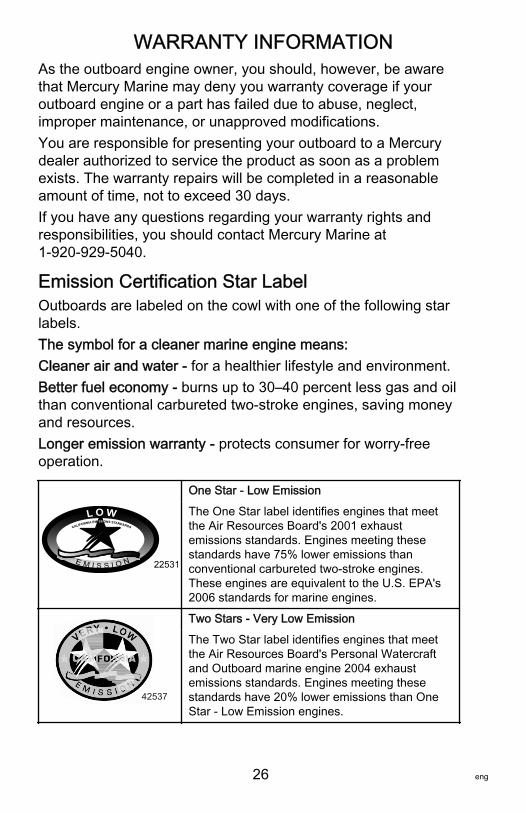
One Star ‑ Low Emission
The One Star label identifies engines that meetthe Air Resources Board's 2001 exhaustemissions standards. Engines meeting thesestandards have 75% lower emissions thanconventional carbureted two‑stroke engines.These engines are equivalent to the U.S. EPA's2006 standards for marine engines.
42537
Two Stars ‑ Very Low Emission
The Two Star label identifies engines that meetthe Air Resources Board's Personal Watercraftand Outboard marine engine 2004 exhaustemissions standards. Engines meeting thesestandards have 20% lower emissions than OneStar ‑ Low Emission engines.
WARRANTY INFORMATION
eng 27
42538
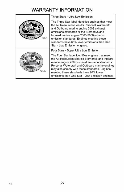
Three Stars ‑ Ultra Low Emission
The Three Star label identifies engines that meetthe Air Resources Board's Personal Watercraftand Outboard marine engine 2008 exhaustemissions standards or the Sterndrive andInboard marine engine 2003‑2008 exhaustemission standards. Engines meeting thesestandards have 65% lower emissions than OneStar ‑ Low Emission engines.
42539
Four Stars ‑ Super Ultra Low Emission
The Four Star label identifies engines that meetthe Air Resources Board's Sterndrive and Inboardmarine engine 2009 exhaust emission standards.Personal Watercraft and Outboard marine enginesmay also comply with these standards. Enginesmeeting these standards have 90% loweremissions than One Star ‑ Low Emission engines.
GENERAL INFORMATION
28 eng
Boater's ResponsibilitiesThe operator (driver) is responsible for the correct and safeoperation of the boat and safety of its occupants and generalpublic. It is strongly recommended that each operator (driver)read and understand this entire manual before operating theoutboard.Be sure at least one additional person onboard is instructed inthe basics of starting and operating the outboard and boathandling in case the driver is unable to operate the boat.
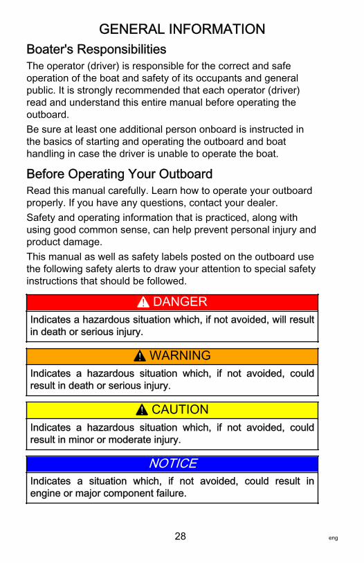
Before Operating Your OutboardRead this manual carefully. Learn how to operate your outboardproperly. If you have any questions, contact your dealer.Safety and operating information that is practiced, along withusing good common sense, can help prevent personal injury andproduct damage.This manual as well as safety labels posted on the outboard usethe following safety alerts to draw your attention to special safetyinstructions that should be followed.
! DANGERIndicates a hazardous situation which, if not avoided, will resultin death or serious injury.
! WARNINGIndicates a hazardous situation which, if not avoided, couldresult in death or serious injury.
! CAUTIONIndicates a hazardous situation which, if not avoided, couldresult in minor or moderate injury.
NOTICEIndicates a situation which, if not avoided, could result inengine or major component failure.
GENERAL INFORMATION
eng 29
Boat Horsepower Capacity
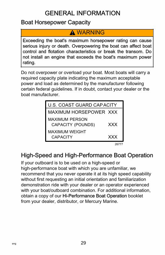
! WARNINGExceeding the boat's maximum horsepower rating can causeserious injury or death. Overpowering the boat can affect boatcontrol and flotation characteristics or break the transom. Donot install an engine that exceeds the boat's maximum powerrating.
Do not overpower or overload your boat. Most boats will carry arequired capacity plate indicating the maximum acceptablepower and load as determined by the manufacturer followingcertain federal guidelines. If in doubt, contact your dealer or theboat manufacturer.
U.S. COAST GUARD CAPACITYMAXIMUM HORSEPOWER XXXMAXIMUM PERSON CAPACITY (POUNDS) XXXMAXIMUM WEIGHT CAPACITY XXX
26777
High‑Speed and High‑Performance Boat OperationIf your outboard is to be used on a high‑speed orhigh‑performance boat with which you are unfamiliar, werecommend that you never operate it at its high speed capabilitywithout first requesting an initial orientation and familiarizationdemonstration ride with your dealer or an operator experiencedwith your boat/outboard combination. For additional information,obtain a copy of our Hi‑Performance Boat Operation bookletfrom your dealer, distributor, or Mercury Marine.
GENERAL INFORMATION
30 eng
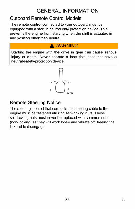
Outboard Remote Control ModelsThe remote control connected to your outboard must beequipped with a start in neutral only protection device. Thisprevents the engine from starting when the shift is actuated inany position other than neutral.
! WARNINGStarting the engine with the drive in gear can cause seriousinjury or death. Never operate a boat that does not have aneutral‑safety‑protection device.
26779
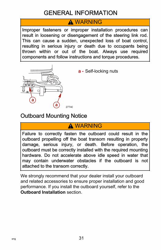
Remote Steering NoticeThe steering link rod that connects the steering cable to theengine must be fastened utilizing self‑locking nuts. Theseself‑locking nuts must never be replaced with common nuts(non‑locking) as they will work loose and vibrate off, freeing thelink rod to disengage.
GENERAL INFORMATION
eng 31
! WARNINGImproper fasteners or improper installation procedures canresult in loosening or disengagement of the steering link rod.This can cause a sudden, unexpected loss of boat control,resulting in serious injury or death due to occupants beingthrown within or out of the boat. Always use requiredcomponents and follow instructions and torque procedures.
a - Self‑locking nuts
Outboard Mounting Notice
! WARNINGFailure to correctly fasten the outboard could result in theoutboard propelling off the boat transom resulting in propertydamage, serious injury, or death. Before operation, theoutboard must be correctly installed with the required mountinghardware. Do not accelerate above idle speed in water thatmay contain underwater obstacles if the outboard is notattached to the transom correctly.
We strongly recommend that your dealer install your outboardand related accessories to ensure proper installation and goodperformance. If you install the outboard yourself, refer to theOutboard Installation section.
aa 27740
GENERAL INFORMATION
32 eng
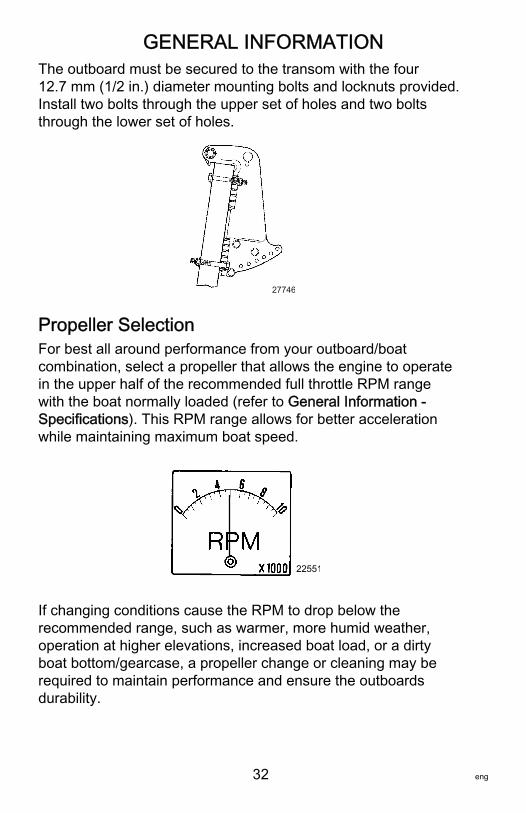
The outboard must be secured to the transom with the four12.7 mm (1/2 in.) diameter mounting bolts and locknuts provided.Install two bolts through the upper set of holes and two boltsthrough the lower set of holes.
27746
Propeller SelectionFor best all around performance from your outboard/boatcombination, select a propeller that allows the engine to operatein the upper half of the recommended full throttle RPM rangewith the boat normally loaded (refer to General Information ‑Specifications). This RPM range allows for better accelerationwhile maintaining maximum boat speed.
22551
If changing conditions cause the RPM to drop below therecommended range, such as warmer, more humid weather,operation at higher elevations, increased boat load, or a dirtyboat bottom/gearcase, a propeller change or cleaning may berequired to maintain performance and ensure the outboardsdurability.
GENERAL INFORMATION
eng 33
Check full‑throttle RPM, using an accurate tachometer, with theengine trimmed out to a balanced‑steering condition (steeringeffort equal in both directions) without causing the propeller tobreak loose.
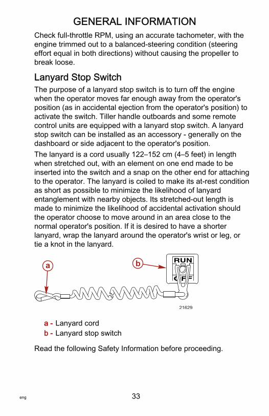
Lanyard Stop SwitchThe purpose of a lanyard stop switch is to turn off the enginewhen the operator moves far enough away from the operator'sposition (as in accidental ejection from the operator's position) toactivate the switch. Tiller handle outboards and some remotecontrol units are equipped with a lanyard stop switch. A lanyardstop switch can be installed as an accessory ‑ generally on thedashboard or side adjacent to the operator's position.The lanyard is a cord usually 122–152 cm (4–5 feet) in lengthwhen stretched out, with an element on one end made to beinserted into the switch and a snap on the other end for attachingto the operator. The lanyard is coiled to make its at‑rest conditionas short as possible to minimize the likelihood of lanyardentanglement with nearby objects. Its stretched‑out length ismade to minimize the likelihood of accidental activation shouldthe operator choose to move around in an area close to thenormal operator's position. If it is desired to have a shorterlanyard, wrap the lanyard around the operator's wrist or leg, ortie a knot in the lanyard.
a - Lanyard cordb - Lanyard stop switch
Read the following Safety Information before proceeding.
21629
a b
GENERAL INFORMATION
34 eng
Important Safety Information: The purpose of a lanyard stopswitch is to stop the engine when the operator moves far enoughaway from the operator's position to activate the switch. Thiswould occur if the operator accidentally falls overboard or moveswithin the boat a sufficient distance from the operator's position.Falling overboard and accidental ejections are more likely tooccur in certain types of boats such as low sided inflatables,bass boats, high performance boats, and light, sensitive handlingfishing boats operated by a hand tiller. Falling overboard andaccidental ejections are also likely to occur as a result of pooroperating practices such as sitting on the back of the seat orgunwale at planing speeds, standing at planing speeds, sittingon elevated fishing boat decks, operating at planing speeds inshallow or obstacle infested waters, releasing your grip on asteering wheel or tiller handle that is pulling in one direction,drinking alcohol or consuming drugs, or daring high speed boatmaneuvers.While activation of the lanyard stop switch will stop the engineimmediately, a boat will continue to coast for some distancedepending upon the velocity and degree of any turn at shutdown. However, the boat will not complete a full circle. While theboat is coasting, it can cause injury to anyone in the boat's pathas seriously as the boat would when under power.We strongly recommend that other occupants be instructed onproper starting and operating procedures should they berequired to operate the engine in an emergency (e.g. if theoperator is accidentally ejected).
! WARNINGIf the operator falls out of the boat, stop the engine immediatelyto reduce the possibility of serious injury or death from beingstruck by the boat. Always properly connect the operator to thestop switch using a lanyard.
GENERAL INFORMATION
eng 35
! WARNINGAvoid serious injury or death from deceleration forces resultingfrom accidental or unintended stop switch activation. The boatoperator should never leave the operator's station without firstdisconnecting the stop switch lanyard from the operator.
Accidental or unintended activation of the switch during normaloperation is also a possibility. This could cause any, or all, of thefollowing potentially hazardous situations:• Occupants could be thrown forward due to unexpected loss
of forward motion ‑ a particular concern for passengers inthe front of the boat who could be ejected over the bow andpossibly struck by the gearcase or propeller.
• Loss of power and directional control in heavy seas, strongcurrent, or high winds.
• Loss of control when docking.
KEEP THE LANYARD STOP SWITCH AND LANYARDCORD IN GOOD OPERATING CONDITIONBefore each use, check to ensure the lanyard stop switch worksproperly. Start the engine and stop it by pulling the lanyard cord.If the engine does not stop, have the switch repaired beforeoperating the boat.Before each use, visually inspect the lanyard cord to ensure it isin good working condition and that there are no breaks, cuts, orwear to the cord. Check that the clips on the ends of the cord arein good condition. Replace any damaged or worn lanyard cords.
GENERAL INFORMATION
36 eng
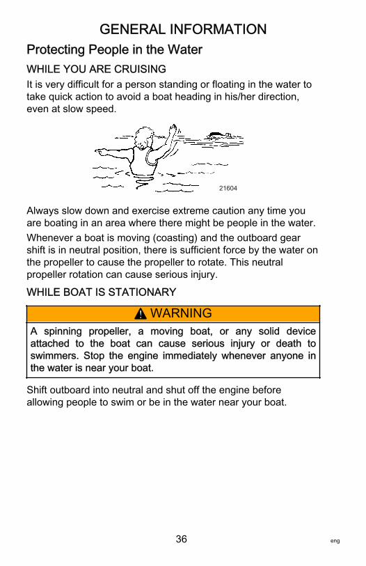
Protecting People in the WaterWHILE YOU ARE CRUISINGIt is very difficult for a person standing or floating in the water totake quick action to avoid a boat heading in his/her direction,even at slow speed.
21604
Always slow down and exercise extreme caution any time youare boating in an area where there might be people in the water.Whenever a boat is moving (coasting) and the outboard gearshift is in neutral position, there is sufficient force by the water onthe propeller to cause the propeller to rotate. This neutralpropeller rotation can cause serious injury.
WHILE BOAT IS STATIONARY
! WARNINGA spinning propeller, a moving boat, or any solid deviceattached to the boat can cause serious injury or death toswimmers. Stop the engine immediately whenever anyone inthe water is near your boat.
Shift outboard into neutral and shut off the engine beforeallowing people to swim or be in the water near your boat.

GENERAL INFORMATION
eng 37
Passenger Safety Message ‑ Pontoon Boats andDeck BoatsWhenever the boat is in motion, observe the location of allpassengers. Do not allow any passengers to stand or use seatsother than those designated for traveling faster than idle speed.A sudden reduction in boat speed, such as plunging into a largewave or wake, a sudden throttle reduction, or a sharp change ofboat direction, could throw them over the front of the boat.Falling over the front of the boat between the two pontoons willposition them to be run over by the outboard.
BOATS HAVING AN OPEN FRONT DECKNo one should ever be on the deck in front of the fence while theboat is in motion. Keep all passengers behind the front fence orenclosure.Persons on the front deck could easily be thrown overboard orpersons dangling their feet over the front edge could get theirlegs caught by a wave and pulled into the water.
26782
! WARNINGSitting or standing in an area of the boat not designed forpassengers at speeds above idle can cause serious injury ordeath. Stay back from the front end of deck boats or raisedplatforms and remain seated while the boat is in motion.
GENERAL INFORMATION
38 eng
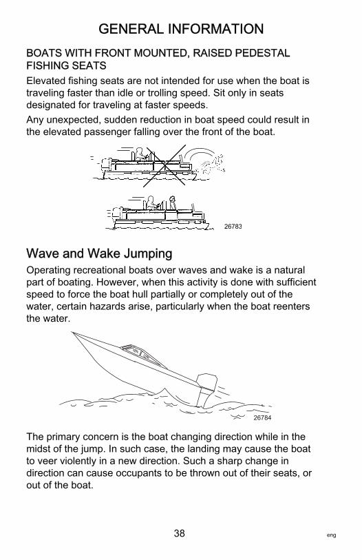
BOATS WITH FRONT MOUNTED, RAISED PEDESTALFISHING SEATSElevated fishing seats are not intended for use when the boat istraveling faster than idle or trolling speed. Sit only in seatsdesignated for traveling at faster speeds.Any unexpected, sudden reduction in boat speed could result inthe elevated passenger falling over the front of the boat.
26783
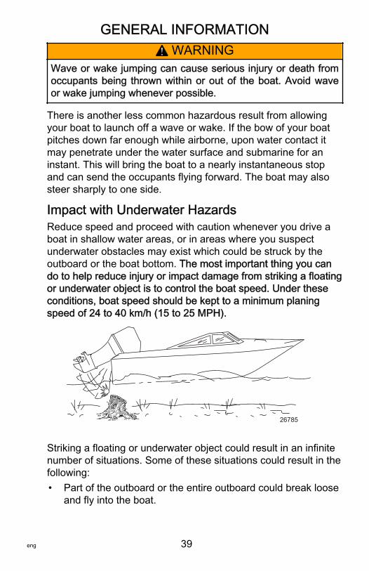
Wave and Wake JumpingOperating recreational boats over waves and wake is a naturalpart of boating. However, when this activity is done with sufficientspeed to force the boat hull partially or completely out of thewater, certain hazards arise, particularly when the boat reentersthe water.
26784
The primary concern is the boat changing direction while in themidst of the jump. In such case, the landing may cause the boatto veer violently in a new direction. Such a sharp change indirection can cause occupants to be thrown out of their seats, orout of the boat.
GENERAL INFORMATION
eng 39
! WARNINGWave or wake jumping can cause serious injury or death fromoccupants being thrown within or out of the boat. Avoid waveor wake jumping whenever possible.
There is another less common hazardous result from allowingyour boat to launch off a wave or wake. If the bow of your boatpitches down far enough while airborne, upon water contact itmay penetrate under the water surface and submarine for aninstant. This will bring the boat to a nearly instantaneous stopand can send the occupants flying forward. The boat may alsosteer sharply to one side.
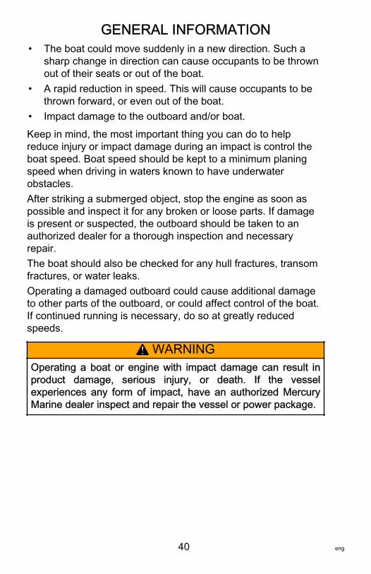
Impact with Underwater HazardsReduce speed and proceed with caution whenever you drive aboat in shallow water areas, or in areas where you suspectunderwater obstacles may exist which could be struck by theoutboard or the boat bottom. The most important thing you cando to help reduce injury or impact damage from striking a floatingor underwater object is to control the boat speed. Under theseconditions, boat speed should be kept to a minimum planingspeed of 24 to 40 km/h (15 to 25 MPH).
26785
Striking a floating or underwater object could result in an infinitenumber of situations. Some of these situations could result in thefollowing:• Part of the outboard or the entire outboard could break loose
and fly into the boat.
GENERAL INFORMATION
40 eng
• The boat could move suddenly in a new direction. Such asharp change in direction can cause occupants to be thrownout of their seats or out of the boat.
• A rapid reduction in speed. This will cause occupants to bethrown forward, or even out of the boat.
• Impact damage to the outboard and/or boat.
Keep in mind, the most important thing you can do to helpreduce injury or impact damage during an impact is control theboat speed. Boat speed should be kept to a minimum planingspeed when driving in waters known to have underwaterobstacles.After striking a submerged object, stop the engine as soon aspossible and inspect it for any broken or loose parts. If damageis present or suspected, the outboard should be taken to anauthorized dealer for a thorough inspection and necessaryrepair.The boat should also be checked for any hull fractures, transomfractures, or water leaks.Operating a damaged outboard could cause additional damageto other parts of the outboard, or could affect control of the boat.If continued running is necessary, do so at greatly reducedspeeds.
! WARNINGOperating a boat or engine with impact damage can result inproduct damage, serious injury, or death. If the vesselexperiences any form of impact, have an authorized MercuryMarine dealer inspect and repair the vessel or power package.

GENERAL INFORMATION
eng 41
Exhaust EmissionsBE ALERT TO CARBON MONOXIDE POISONINGCarbon monoxide (CO) is a deadly gas that is present in theexhaust fumes of all internal combustion engines, including theengines that propel boats, and the generators that power boataccessories. By itself, CO is odorless, colorless, and tasteless,but if you can smell or taste engine exhaust, you are inhalingCO.Early symptoms of carbon monoxide poisoning, which are similarto the symptoms of seasickness and intoxication, includeheadache, dizziness, drowsiness, and nausea.
! WARNINGInhaling engine exhaust gases can result in carbon monoxidepoisoning, which can lead to unconsciousness, brain damage,or death. Avoid exposure to carbon monoxide.Stay clear from exhaust areas when engine is running. Keepthe boat well‑ventilated while at rest or underway.
STAY CLEAR OF EXHAUST AREAS
41127
Engine exhaust gases contain harmful carbon monoxide. Avoidareas of concentrated engine exhaust gases. When engines arerunning, keep swimmers away from the boat, and do not sit, lie,or stand on swim platforms or boarding ladders. While underway,do not allow passengers to be positioned immediately behind theboat (platform dragging, teak/body surfing). This dangerouspractice not only places a person in an area of high engineexhaust concentration, but also subjects them to the possibility ofinjury from the boat propeller.
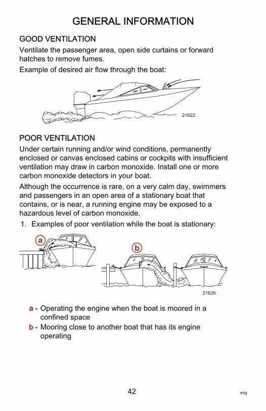
GENERAL INFORMATION
42 eng
GOOD VENTILATIONVentilate the passenger area, open side curtains or forwardhatches to remove fumes.Example of desired air flow through the boat:
21622
POOR VENTILATIONUnder certain running and/or wind conditions, permanentlyenclosed or canvas enclosed cabins or cockpits with insufficientventilation may draw in carbon monoxide. Install one or morecarbon monoxide detectors in your boat.Although the occurrence is rare, on a very calm day, swimmersand passengers in an open area of a stationary boat thatcontains, or is near, a running engine may be exposed to ahazardous level of carbon monoxide.1. Examples of poor ventilation while the boat is stationary:
a - Operating the engine when the boat is moored in aconfined space
b - Mooring close to another boat that has its engineoperating
21626
ab
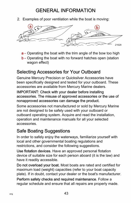
GENERAL INFORMATION
eng 43
2. Examples of poor ventilation while the boat is moving:
a - Operating the boat with the trim angle of the bow too highb - Operating the boat with no forward hatches open (station
wagon effect)
Selecting Accessories for Your OutboardGenuine Mercury Precision or Quicksilver Accessories havebeen specifically designed and tested for your outboard. Theseaccessories are available from Mercury Marine dealers.IMPORTANT: Check with your dealer before installingaccessories. The misuse of approved accessories or the use ofnonapproved accessories can damage the product.Some accessories not manufactured or sold by Mercury Marineare not designed to be safely used with your outboard oroutboard operating system. Acquire and read the installation,operation and maintenance manuals for all your selectedaccessories.
Safe Boating SuggestionsIn order to safely enjoy the waterways, familiarize yourself withlocal and other governmental boating regulations andrestrictions, and consider the following suggestions.Use flotation devices. Have an approved personal flotationdevice of suitable size for each person aboard (it is the law) andhave it readily accessible.Do not overload your boat. Most boats are rated and certified formaximum load (weight) capacities (refer to your boat capacityplate). If in doubt, contact your dealer or the boat's manufacturer.Perform safety checks and required maintenance. Follow aregular schedule and ensure that all repairs are properly made.
a b
21628
GENERAL INFORMATION
44 eng
Know and obey all nautical rules and laws of the waterways.Boat operators should complete a boating safety course.Courses are offered in the U.S.A. by 1) the U.S. Coast GuardAuxiliary, 2) the Power Squadron, 3) the Red Cross, and 4) yourstate boating law enforcement agency. Inquiries may be made tothe Boating Hotline, 1‑800‑368‑5647 or the Boat U.S. Foundationinformation number 1‑800‑336‑BOAT.Make sure everyone in the boat is properly seated. Do not allowanyone to sit or ride on any part of the boat that was notintended for such use. This includes the back of seats,gunwales, transom, bow, decks, raised fishing seats, anyrotating fishing seat; or anywhere that an unexpectedacceleration, sudden stopping, unexpected loss of boat control,or sudden boat movement could cause a person to be thrownoverboard or into the boat.Never be under the influence of alcohol or drugs while boating (itis the law). Alcohol or drug use impairs your judgment andgreatly reduces your ability to react quickly.Prepare other boat operators. Instruct at least one other persononboard in the basics of starting and operating the outboard, andboat handling, in case the driver becomes disabled or fallsoverboard.Passenger boarding. Stop the engine whenever passengers areboarding, unloading, or are near the back (stern) of the boat.Just shifting the outboard into neutral is not sufficient.Be alert. The operator of the boat is responsible by law tomaintain a proper lookout by sight and hearing. The operatormust have an unobstructed view particularly to the front. Nopassengers, load, or fishing seats should block the operator'sview when operating the boat above idle speed.Never drive your boat directly behind a water‑skier in case theskier falls. As an example, your boat traveling at 40 km/h(25 MPH) will overtake a fallen skier 61 m (200 ft) in front of youin 5 seconds.
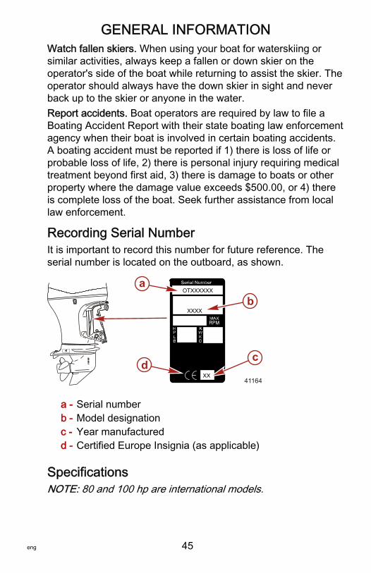
GENERAL INFORMATION
eng 45
Watch fallen skiers. When using your boat for waterskiing orsimilar activities, always keep a fallen or down skier on theoperator's side of the boat while returning to assist the skier. Theoperator should always have the down skier in sight and neverback up to the skier or anyone in the water.Report accidents. Boat operators are required by law to file aBoating Accident Report with their state boating law enforcementagency when their boat is involved in certain boating accidents.A boating accident must be reported if 1) there is loss of life orprobable loss of life, 2) there is personal injury requiring medicaltreatment beyond first aid, 3) there is damage to boats or otherproperty where the damage value exceeds $500.00, or 4) thereis complete loss of the boat. Seek further assistance from locallaw enforcement.
Recording Serial NumberIt is important to record this number for future reference. Theserial number is located on the outboard, as shown.
a - Serial numberb - Model designationc - Year manufacturedd - Certified Europe Insignia (as applicable)
SpecificationsNOTE: 80 and 100 hp are international models.
XX
OTXXXXXX
XXXX
ab
cd
41164
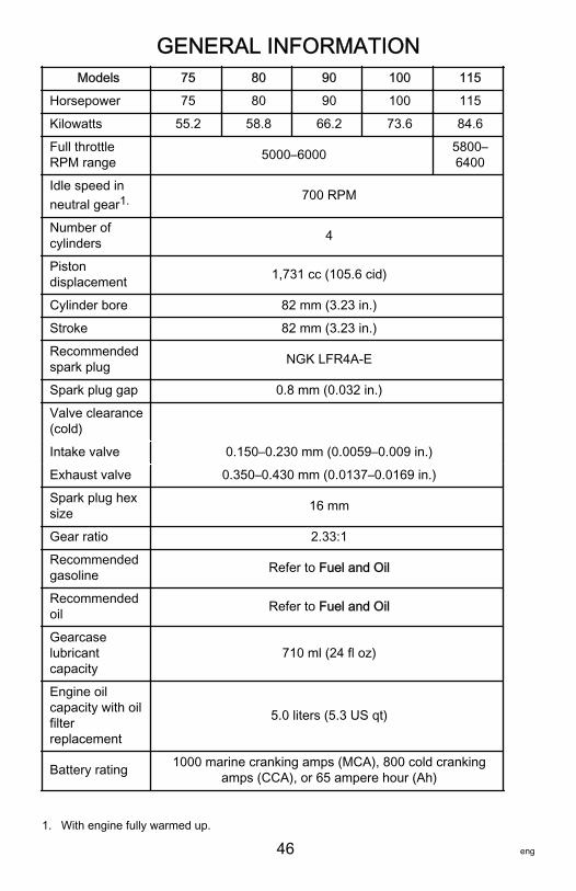
GENERAL INFORMATION
46 eng
Models 75 80 90 100 115
Horsepower 75 80 90 100 115
Kilowatts 55.2 58.8 66.2 73.6 84.6
Full throttleRPM range 5000–6000 5800–
6400
Idle speed inneutral gear1. 700 RPM
Number ofcylinders 4
Pistondisplacement 1,731 cc (105.6 cid)
Cylinder bore 82 mm (3.23 in.)
Stroke 82 mm (3.23 in.)
Recommendedspark plug NGK LFR4A‑E
Spark plug gap 0.8 mm (0.032 in.)
Valve clearance(cold)
Intake valve 0.150–0.230 mm (0.0059–0.009 in.)
Exhaust valve 0.350–0.430 mm (0.0137–0.0169 in.)
Spark plug hexsize 16 mm
Gear ratio 2.33:1
Recommendedgasoline Refer to Fuel and Oil
Recommendedoil Refer to Fuel and Oil
Gearcaselubricantcapacity
710 ml (24 fl oz)
Engine oilcapacity with oilfilterreplacement
5.0 liters (5.3 US qt)
Battery rating 1000 marine cranking amps (MCA), 800 cold crankingamps (CCA), or 65 ampere hour (Ah)
1. With engine fully warmed up.
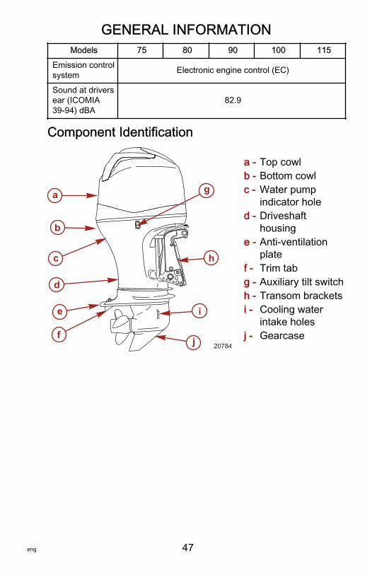
GENERAL INFORMATION
eng 47
Models 75 80 90 100 115
Emission controlsystem Electronic engine control (EC)
Sound at driversear (ICOMIA39‑94) dBA
82.9
Component Identification
a - Top cowlb - Bottom cowlc - Water pump
indicator holed - Driveshaft
housinge - Anti‑ventilation
platef - Trim tabg - Auxiliary tilt switchh - Transom bracketsi - Cooling water
intake holesj - Gearcase
a
b
c
d
e
f
g
h
i
j 20784
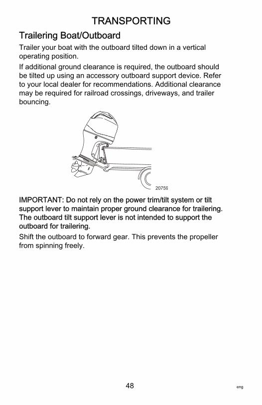
TRANSPORTING
48 eng
Trailering Boat/OutboardTrailer your boat with the outboard tilted down in a verticaloperating position.If additional ground clearance is required, the outboard shouldbe tilted up using an accessory outboard support device. Referto your local dealer for recommendations. Additional clearancemay be required for railroad crossings, driveways, and trailerbouncing.
20759
IMPORTANT: Do not rely on the power trim/tilt system or tiltsupport lever to maintain proper ground clearance for trailering.The outboard tilt support lever is not intended to support theoutboard for trailering.Shift the outboard to forward gear. This prevents the propellerfrom spinning freely.
FUEL AND OIL
eng 49
Fuel RecommendationsIMPORTANT: Use of improper gasoline can damage yourengine. Engine damage resulting from the use of impropergasoline is considered misuse of the engine, and damagecaused thereby will not be covered under the limitedwarranty.FUEL RATINGSMercury Marine engines will operate satisfactorily when using amajor brand of unleaded gasoline meeting the followingspecifications:USA and Canada ‑ having a posted pump Octane Rating of 87(R+M)/2 minimum. Premium gasoline [92 (R+M)/2 Octane] isalso acceptable. Do not use leaded gasoline.Outside USA and Canada ‑ having a posted pump OctaneRating of 90 RON minimum. Premium gasoline (98 RON) is alsoacceptable. Do not use leaded gasoline.
USING REFORMULATED (OXYGENATED) GASOLINES(USA ONLY)This type of gasoline is required in certain areas of the USA. The2 types of oxygenates used in these fuels are Alcohol (Ethanol)or Ether (MTBE or ETBE). If Ethanol is the oxygenate that isused in the gasoline in your area, refer to Gasolines ContainingAlcohol.These Reformulated Gasolines are acceptable for use in yourMercury Marine engine.
GASOLINES CONTAINING ALCOHOLIf the gasoline in your area contains either methanol (methylalcohol) or ethanol (ethyl alcohol), you should be aware ofcertain adverse effects that can occur. These adverse effects aremore severe with methanol. Increasing the percentage of alcoholin the fuel can also worsen these adverse effects.Some of these adverse effects are caused because the alcoholin the gasoline can absorb moisture from the air, resulting in aseparation of the water/alcohol from the gasoline in the fuel tank.
FUEL AND OIL
50 eng
The fuel system components on your Mercury Marine engine willwithstand up to 10% alcohol content in the gasoline. We do notknow what percentage your boat's fuel system will withstand.Contact your boat manufacturer for specific recommendations onthe boat's fuel system components (fuel tanks, fuel lines, andfittings). Be aware that gasolines containing alcohol may causeincreased:• Corrosion of metal parts• Deterioration of rubber or plastic parts• Fuel permeation through rubber fuel lines• Starting and operating difficulties
! WARNINGFuel leakage is a fire or explosion hazard, which can causeserious injury or death. Periodically inspect all fuel systemcomponents for leaks, softening, hardening, swelling, orcorrosion, particularly after storage. Any sign of leakage ordeterioration requires replacement before further engineoperation.
Because of possible adverse effects of alcohol in gasoline, it isrecommended that only alcohol‑free gasoline be used wherepossible. If only fuel containing alcohol is available, or if thepresence of alcohol is unknown, increased inspection frequencyfor leaks and abnormalities is required.IMPORTANT: When operating a Mercury Marine engine ongasoline containing alcohol, storage of gasoline in the fuel tankfor long periods should be avoided. Long periods of storage,common to boats, create unique problems. In cars, alcohol‑blendfuels normally are consumed before they can absorb enoughmoisture to cause trouble, but boats often sit idle long enough forphase separation to take place. In addition, internal corrosionmay take place during storage if alcohol has washed protectiveoil films from internal components.
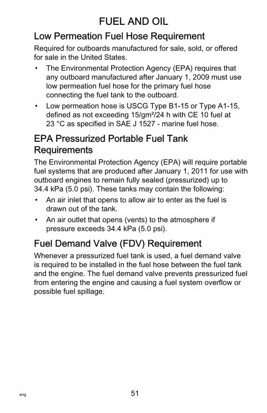
FUEL AND OIL
eng 51
Low Permeation Fuel Hose RequirementRequired for outboards manufactured for sale, sold, or offeredfor sale in the United States.• The Environmental Protection Agency (EPA) requires that
any outboard manufactured after January 1, 2009 must uselow permeation fuel hose for the primary fuel hoseconnecting the fuel tank to the outboard.
• Low permeation hose is USCG Type B1‑15 or Type A1‑15,defined as not exceeding 15/gm²/24 h with CE 10 fuel at23 °C as specified in SAE J 1527 ‑ marine fuel hose.
EPA Pressurized Portable Fuel TankRequirementsThe Environmental Protection Agency (EPA) will require portablefuel systems that are produced after January 1, 2011 for use withoutboard engines to remain fully sealed (pressurized) up to34.4 kPa (5.0 psi). These tanks may contain the following:• An air inlet that opens to allow air to enter as the fuel is
drawn out of the tank.• An air outlet that opens (vents) to the atmosphere if
pressure exceeds 34.4 kPa (5.0 psi).
Fuel Demand Valve (FDV) RequirementWhenever a pressurized fuel tank is used, a fuel demand valveis required to be installed in the fuel hose between the fuel tankand the engine. The fuel demand valve prevents pressurized fuelfrom entering the engine and causing a fuel system overflow orpossible fuel spillage.
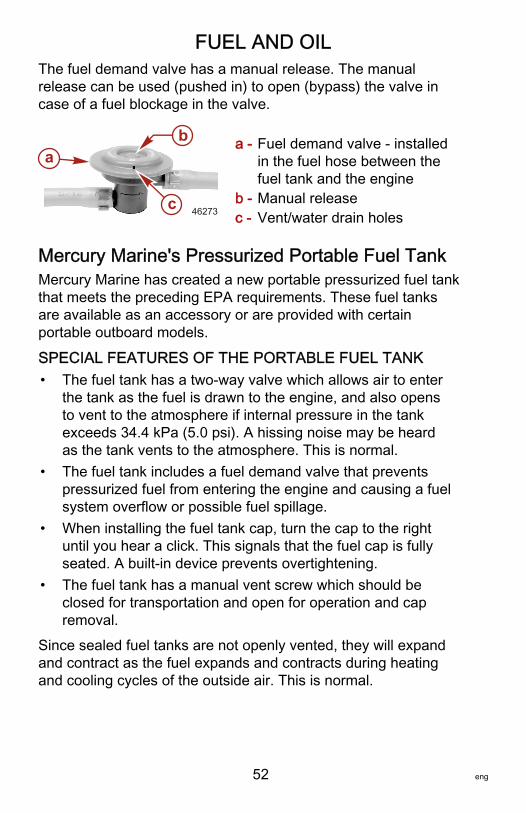
FUEL AND OIL
52 eng
The fuel demand valve has a manual release. The manualrelease can be used (pushed in) to open (bypass) the valve incase of a fuel blockage in the valve.
a - Fuel demand valve ‑ installedin the fuel hose between thefuel tank and the engine
b - Manual releasec - Vent/water drain holes
Mercury Marine's Pressurized Portable Fuel TankMercury Marine has created a new portable pressurized fuel tankthat meets the preceding EPA requirements. These fuel tanksare available as an accessory or are provided with certainportable outboard models.
SPECIAL FEATURES OF THE PORTABLE FUEL TANK• The fuel tank has a two‑way valve which allows air to enter
the tank as the fuel is drawn to the engine, and also opensto vent to the atmosphere if internal pressure in the tankexceeds 34.4 kPa (5.0 psi). A hissing noise may be heardas the tank vents to the atmosphere. This is normal.
• The fuel tank includes a fuel demand valve that preventspressurized fuel from entering the engine and causing a fuelsystem overflow or possible fuel spillage.
• When installing the fuel tank cap, turn the cap to the rightuntil you hear a click. This signals that the fuel cap is fullyseated. A built‑in device prevents overtightening.
• The fuel tank has a manual vent screw which should beclosed for transportation and open for operation and capremoval.
Since sealed fuel tanks are not openly vented, they will expandand contract as the fuel expands and contracts during heatingand cooling cycles of the outside air. This is normal.
a
c
b
46273
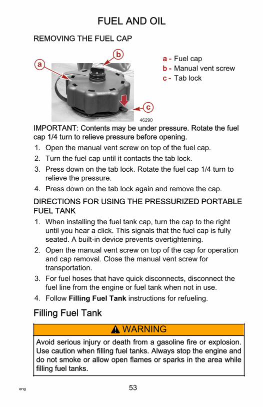
FUEL AND OIL
eng 53
REMOVING THE FUEL CAP
a - Fuel capb - Manual vent screwc - Tab lock
IMPORTANT: Contents may be under pressure. Rotate the fuelcap 1/4 turn to relieve pressure before opening.1. Open the manual vent screw on top of the fuel cap.2. Turn the fuel cap until it contacts the tab lock.3. Press down on the tab lock. Rotate the fuel cap 1/4 turn to
relieve the pressure.4. Press down on the tab lock again and remove the cap.
DIRECTIONS FOR USING THE PRESSURIZED PORTABLEFUEL TANK1. When installing the fuel tank cap, turn the cap to the right
until you hear a click. This signals that the fuel cap is fullyseated. A built‑in device prevents overtightening.
2. Open the manual vent screw on top of the cap for operationand cap removal. Close the manual vent screw fortransportation.
3. For fuel hoses that have quick disconnects, disconnect thefuel line from the engine or fuel tank when not in use.
4. Follow Filling Fuel Tank instructions for refueling.
Filling Fuel Tank
! WARNINGAvoid serious injury or death from a gasoline fire or explosion.Use caution when filling fuel tanks. Always stop the engine anddo not smoke or allow open flames or sparks in the area whilefilling fuel tanks.
ab
c46290
FUEL AND OIL
54 eng
Fill fuel tanks outdoors away from heat, sparks, and openflames.Remove portable fuel tanks from boat to refill them.Always stop engine before refilling tanks.Do not completely fill the fuel tanks. Leave approximately 10% ofthe tank volume unfilled. Fuel will expand in volume as itstemperature rises and can leak under pressure if the tank iscompletely filled.
PORTABLE FUEL TANK PLACEMENT IN THE BOATPlace the fuel tank in the boat so the vent is higher than the fuellevel under normal boat operating conditions.
Engine Oil RecommendationsMercury or Quicksilver NMMA FC‑W certified synthetic blend25W‑40 multi‑viscosity 4‑Stroke Outboard Oil is recommendedfor general, all‑temperature use. If the recommended Mercury orQuicksilver NMMA FC‑W certified oil is not available, a majorbrand of NMMA FC‑W certified 4‑Stroke Outboard Oil of similarviscosity may be used.IMPORTANT: The use of non‑detergent oils, multi‑viscosity oils(other than Mercury or Quicksilver NMMA FC‑W certified oil or amajor brand NMMA FC‑W certified oil), synthetic oils, low qualityoils or oils that contain solid additives are not recommended.
C
+100+80+60+40+20
0
+38+120 +49
+27+16+4-7-18
F
MERCURY 4-STROKE ENGINE OILOIL CAPACITY: 5.0L (5.3 U.S.qt.)
20862
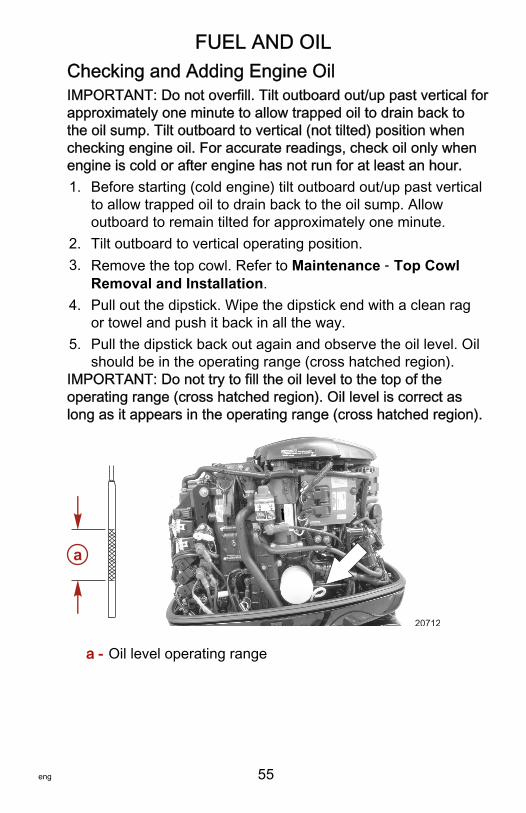
FUEL AND OIL
eng 55
Checking and Adding Engine OilIMPORTANT: Do not overfill. Tilt outboard out/up past vertical forapproximately one minute to allow trapped oil to drain back tothe oil sump. Tilt outboard to vertical (not tilted) position whenchecking engine oil. For accurate readings, check oil only whenengine is cold or after engine has not run for at least an hour.1. Before starting (cold engine) tilt outboard out/up past vertical
to allow trapped oil to drain back to the oil sump. Allowoutboard to remain tilted for approximately one minute.
2. Tilt outboard to vertical operating position.3. Remove the top cowl. Refer to Maintenance ‑ Top Cowl
Removal and Installation.4. Pull out the dipstick. Wipe the dipstick end with a clean rag
or towel and push it back in all the way.5. Pull the dipstick back out again and observe the oil level. Oil
should be in the operating range (cross hatched region).IMPORTANT: Do not try to fill the oil level to the top of theoperating range (cross hatched region). Oil level is correct aslong as it appears in the operating range (cross hatched region).
a - Oil level operating range
a
20712
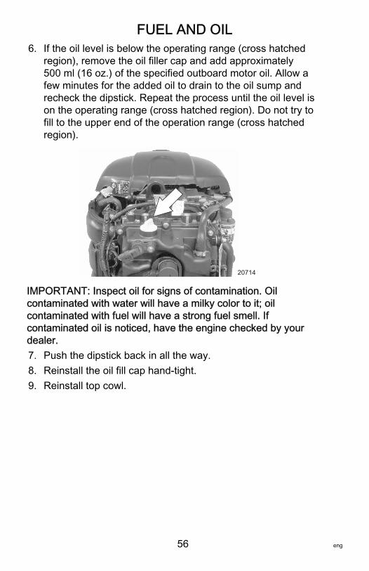
FUEL AND OIL
56 eng
6. If the oil level is below the operating range (cross hatchedregion), remove the oil filler cap and add approximately500 ml (16 oz.) of the specified outboard motor oil. Allow afew minutes for the added oil to drain to the oil sump andrecheck the dipstick. Repeat the process until the oil level ison the operating range (cross hatched region). Do not try tofill to the upper end of the operation range (cross hatchedregion).
20714
IMPORTANT: Inspect oil for signs of contamination. Oilcontaminated with water will have a milky color to it; oilcontaminated with fuel will have a strong fuel smell. Ifcontaminated oil is noticed, have the engine checked by yourdealer.7. Push the dipstick back in all the way.8. Reinstall the oil fill cap hand‑tight.9. Reinstall top cowl.
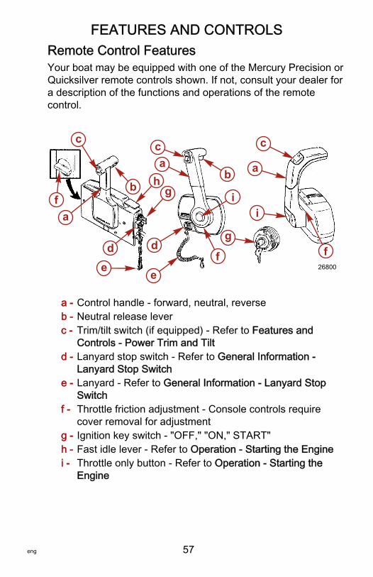
FEATURES AND CONTROLS
eng 57
Remote Control FeaturesYour boat may be equipped with one of the Mercury Precision orQuicksilver remote controls shown. If not, consult your dealer fora description of the functions and operations of the remotecontrol.
a - Control handle ‑ forward, neutral, reverseb - Neutral release leverc - Trim/tilt switch (if equipped) ‑ Refer to Features and
Controls ‑ Power Trim and Tiltd - Lanyard stop switch ‑ Refer to General Information ‑
Lanyard Stop Switche - Lanyard ‑ Refer to General Information ‑ Lanyard Stop
Switchf - Throttle friction adjustment ‑ Console controls require
cover removal for adjustmentg - Ignition key switch ‑ "OFF," "ON," START"h - Fast idle lever ‑ Refer to Operation ‑ Starting the Enginei - Throttle only button ‑ Refer to Operation ‑ Starting the
Engine
fa
c
de
b h
ca
g
d
e
b
i
f
g
i
c
a
f26800
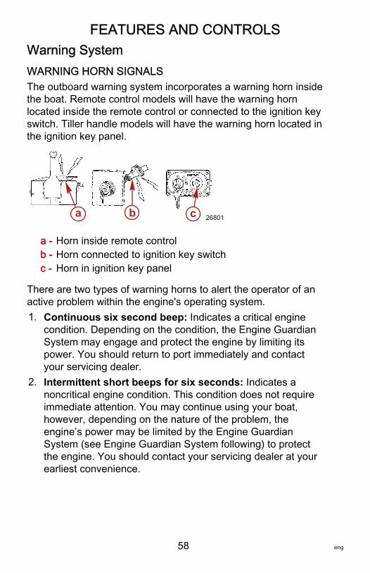
FEATURES AND CONTROLS
58 eng
Warning SystemWARNING HORN SIGNALSThe outboard warning system incorporates a warning horn insidethe boat. Remote control models will have the warning hornlocated inside the remote control or connected to the ignition keyswitch. Tiller handle models will have the warning horn located inthe ignition key panel.
a - Horn inside remote controlb - Horn connected to ignition key switchc - Horn in ignition key panel
There are two types of warning horns to alert the operator of anactive problem within the engine's operating system.1. Continuous six second beep: Indicates a critical engine
condition. Depending on the condition, the Engine GuardianSystem may engage and protect the engine by limiting itspower. You should return to port immediately and contactyour servicing dealer.
2. Intermittent short beeps for six seconds: Indicates anoncritical engine condition. This condition does not requireimmediate attention. You may continue using your boat,however, depending on the nature of the problem, theengine’s power may be limited by the Engine GuardianSystem (see Engine Guardian System following) to protectthe engine. You should contact your servicing dealer at yourearliest convenience.
a b c 26801
FEATURES AND CONTROLS
eng 59
It is important to note that in either of the above scenarios, thehorn will only sound one time. If you key the engine off andrestart it, the horn will sound again, one time, if the fault is stillpresent. For visual display of the specific engine functions andadditional engine data, refer to SmartCraft Product information,following.The operator is able to correct a couple engine problemsindicated by the warning horn. These conditions are as follows:• Cooling system (water pressure or engine temperature)
problem. The warning horn will sound Intermittent shortbeeps for six seconds. Stop the engine and check the waterintake holes in the gearcase for obstruction.
• Low oil pressure problem. The warning horn will sound acontinuous six second beep. Stop the engine and check forlow engine oil level. Refer to Fuel and Oil – Checking andAdding Engine Oil.
ENGINE GUARDIAN SYSTEMThe Engine Guardian System monitors the critical sensors onthe engine for any early indications of problems. EngineGuardian is functional whenever your engine is operating, so younever have to be concerned about whether or not you areprotected. The system will respond to a problem by sounding thewarning horn for six seconds and/or reducing engine power inorder to provide engine protection.If the Guardian System has been activated, reduce throttlespeed. The problem will need to be identified and corrected, ifpossible. The system must be reset before the engine willoperate at higher speeds. Moving the throttle lever back to theidle position will reset the system.
SMARTCRAFT PRODUCTA Mercury SmartCraft System instrument package can bepurchased for this outboard. A few of the functions theinstrument package will display are engine RPM, coolanttemperature, oil pressure, water pressure, battery voltage, fuelconsumption, and engine operating hours.
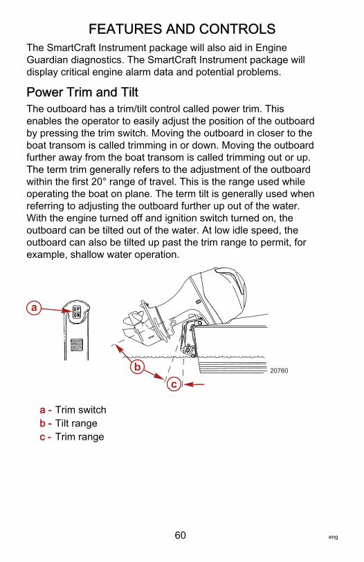
FEATURES AND CONTROLS
60 eng
The SmartCraft Instrument package will also aid in EngineGuardian diagnostics. The SmartCraft Instrument package willdisplay critical engine alarm data and potential problems.
Power Trim and TiltThe outboard has a trim/tilt control called power trim. Thisenables the operator to easily adjust the position of the outboardby pressing the trim switch. Moving the outboard in closer to theboat transom is called trimming in or down. Moving the outboardfurther away from the boat transom is called trimming out or up.The term trim generally refers to the adjustment of the outboardwithin the first 20° range of travel. This is the range used whileoperating the boat on plane. The term tilt is generally used whenreferring to adjusting the outboard further up out of the water.With the engine turned off and ignition switch turned on, theoutboard can be tilted out of the water. At low idle speed, theoutboard can also be tilted up past the trim range to permit, forexample, shallow water operation.
a - Trim switchb - Tilt rangec - Trim range
a
cb 20760
FEATURES AND CONTROLS
eng 61
POWER TRIM OPERATIONWith most boats, operating around the middle of the trim rangewill give satisfactory results. However, to take full advantage ofthe trimming capability there may be times when you choose totrim your outboard all the way in or out. Along with animprovement in some performance aspects comes a greaterresponsibility for the operator, and this is being aware of somepotential control hazards.The most significant control hazard is a pull or torque that can befelt on the steering wheel or tiller handle. This steering torqueresults from the outboard being trimmed so the propeller shaft isnot parallel to the water surface.
! WARNINGTrimming the outboard beyond a neutral steering conditionmay result in a pull on the steering wheel or tiller handle andloss of boat control. Maintain control of the boat if trimmingbeyond a neutral steering condition.
Consider the following lists carefully.1. Trimming in or down can:
• Lower the bow• Result in quicker planing off, especially with a heavy load
or a stern heavy boat• Generally improve the ride in choppy water• Increase steering torque or pull to the right (with the
normal right‑hand rotation propeller)• In excess, can lower the bow of some boats to a point
where they begin to plow with their bow in the water whileon plane. This can result in an unexpected turn in eitherdirection (called bow steering or oversteering) if any turnis attempted, or if a significant wave is encountered.
FEATURES AND CONTROLS
62 eng
! WARNINGOperating the boat at high speeds with the outboard trimmedtoo far under can create excessive bow steer, resulting in theoperator losing control of the boat. Install the trim limit pin in aposition that prevents excessive trim under and operate theboat in a safe manner.
• In rare circumstances, the owner may decide to limit thetrim in. This can be accomplished by purchasing astainless steel tilt pin from your dealer and inserting it inwhatever adjustment hole in the transom brackets isdesired. The nonstainless steel shipping bolt should notbe used in this application other than on a temporarybasis.
2. Trimming out or up can:• Lift the bow higher out of the water• Generally increase top speed• Increase clearance over submerged objects or a shallow
bottom• Increase steering torque or pull to the left at a normal
installation height (with the normal right‑hand rotationpropeller)
• In excess, can cause boat porpoising (bouncing) orpropeller ventilation
• Cause engine overheating if any cooling water intakeholes are above the waterline
TILTING OPERATIONTo tilt outboard, shut off the engine and press the trim/tilt switchor auxiliary tilt switch to the up position. The outboard will tilt upuntil the switch is released or it reaches its maximum tilt position.1. Engage the tilt support lever by rotating the knob to bring the
support lever upward.2. Lower the outboard to rest on the tilt support lever.

FEATURES AND CONTROLS
eng 63
3. Disengage the tilt support lever by raising the outboard offthe support lever and rotating the lever down. Lower theoutboard.
a - Tilt support leverb - Knob
MANUAL TILTINGIf the outboard cannot be tilted using the power trim/tilt switch,the outboard can be manually tilted.NOTE: The manual tilt release valve must be tightened beforeoperating the outboard to prevent the outboard from tilting upduring reverse operation.Turn out the manual tilt release valve three turnscounterclockwise. This allows manual tilting of the outboard. Tiltthe outboard to the desired position and tighten the manual tiltrelease valve.
22362
b
a
27778
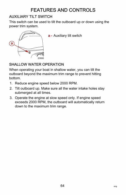
FEATURES AND CONTROLS
64 eng
AUXILIARY TILT SWITCHThis switch can be used to tilt the outboard up or down using thepower trim system.
a - Auxiliary tilt switch
SHALLOW WATER OPERATIONWhen operating your boat in shallow water, you can tilt theoutboard beyond the maximum trim range to prevent hittingbottom.1. Reduce engine speed below 2000 RPM.2. Tilt outboard up. Make sure all the water intake holes stay
submerged at all times.3. Operate the engine at slow speed only. If engine speed
exceeds 2000 RPM, the outboard will automatically returndown to the maximum trim range.
a
20886
OPERATION
eng 65
Prestarting Check List• Operator knows safe navigation, boating, and operating
procedures.• An approved personal flotation device of suitable size for
each person aboard and readily accessible (it is the law).• A ring type life buoy or buoyant cushion designed to be
thrown to a person in the water.• Know your boats' maximum load capacity. Look at the boat
capacity plate.• Fuel supply OK.• Arrange passengers and load in the boat so the weight is
distributed evenly and everyone is seated in a proper seat.• Tell someone where you are going and when you expect to
return.• It is illegal to operate a boat while under the influence of
alcohol or drugs.• Know the waters and area you will be boating; tides,
currents, sand bars, rocks, and other hazards.• Make inspection checks listed in Maintenance ‑ Inspection
and Maintenance Schedule.
Operating in Freezing TemperaturesWhen using your outboard or having your outboard moored infreezing or near freezing temperatures, keep the outboard tilteddown at all times so the gearcase is submerged. This preventsthe trapped water in the gearcase from freezing and causingpossible damage to the water pump and other components.If there is a chance of ice forming on the water, the outboardshould be removed and drained completely of water. If iceshould form at the water level inside the outboard driveshafthousing, it will block water flow to the engine causing possibledamage.
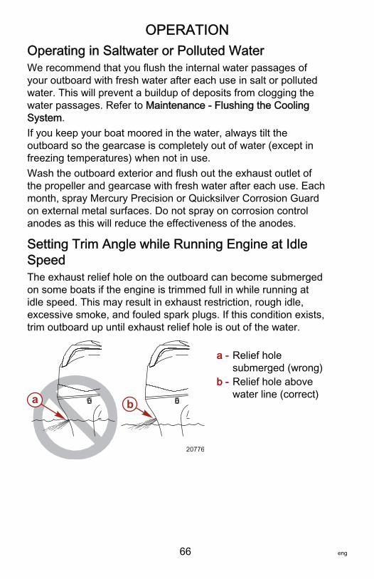
OPERATION
66 eng
Operating in Saltwater or Polluted WaterWe recommend that you flush the internal water passages ofyour outboard with fresh water after each use in salt or pollutedwater. This will prevent a buildup of deposits from clogging thewater passages. Refer to Maintenance ‑ Flushing the CoolingSystem.If you keep your boat moored in the water, always tilt theoutboard so the gearcase is completely out of water (except infreezing temperatures) when not in use.Wash the outboard exterior and flush out the exhaust outlet ofthe propeller and gearcase with fresh water after each use. Eachmonth, spray Mercury Precision or Quicksilver Corrosion Guardon external metal surfaces. Do not spray on corrosion controlanodes as this will reduce the effectiveness of the anodes.
Setting Trim Angle while Running Engine at IdleSpeedThe exhaust relief hole on the outboard can become submergedon some boats if the engine is trimmed full in while running atidle speed. This may result in exhaust restriction, rough idle,excessive smoke, and fouled spark plugs. If this condition exists,trim outboard up until exhaust relief hole is out of the water.
a - Relief holesubmerged (wrong)
b - Relief hole abovewater line (correct)a b
20776
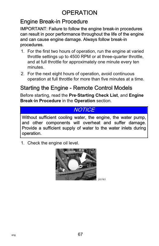
OPERATION
eng 67
Engine Break‑in ProcedureIMPORTANT: Failure to follow the engine break‑in procedurescan result in poor performance throughout the life of the engineand can cause engine damage. Always follow break‑inprocedures.1. For the first two hours of operation, run the engine at varied
throttle settings up to 4500 RPM or at three‑quarter throttle,and at full throttle for approximately one minute every tenminutes.
2. For the next eight hours of operation, avoid continuousoperation at full throttle for more than five minutes at a time.
Starting the Engine ‑ Remote Control ModelsBefore starting, read the Pre‑Starting Check List, and EngineBreak‑in Procedure in the Operation section.
NOTICEWithout sufficient cooling water, the engine, the water pump,and other components will overheat and suffer damage.Provide a sufficient supply of water to the water inlets duringoperation.
1. Check the engine oil level.
20783
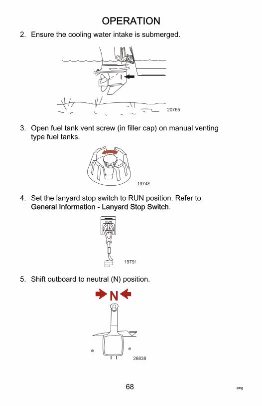
OPERATION
68 eng
2. Ensure the cooling water intake is submerged.
20765
3. Open fuel tank vent screw (in filler cap) on manual ventingtype fuel tanks.
19748
4. Set the lanyard stop switch to RUN position. Refer toGeneral Information ‑ Lanyard Stop Switch.
19791
5. Shift outboard to neutral (N) position.
N
26838
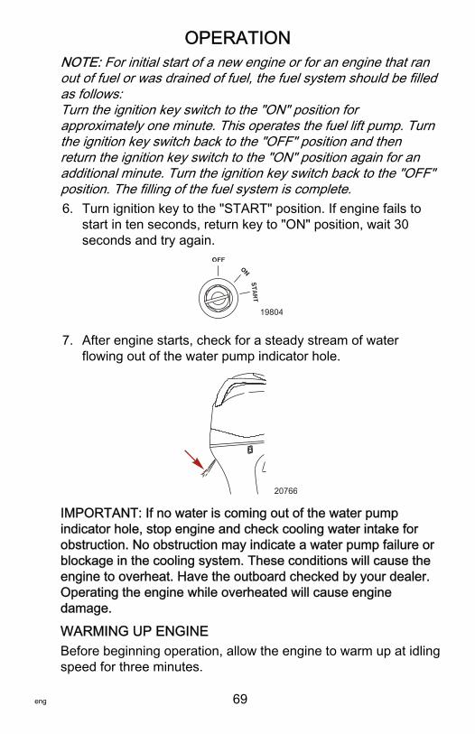
OPERATION
eng 69
NOTE: For initial start of a new engine or for an engine that ranout of fuel or was drained of fuel, the fuel system should be filledas follows:Turn the ignition key switch to the "ON" position forapproximately one minute. This operates the fuel lift pump. Turnthe ignition key switch back to the "OFF" position and thenreturn the ignition key switch to the "ON" position again for anadditional minute. Turn the ignition key switch back to the "OFF"position. The filling of the fuel system is complete.6. Turn ignition key to the "START" position. If engine fails to
start in ten seconds, return key to "ON" position, wait 30seconds and try again.
19804
7. After engine starts, check for a steady stream of waterflowing out of the water pump indicator hole.
20766
IMPORTANT: If no water is coming out of the water pumpindicator hole, stop engine and check cooling water intake forobstruction. No obstruction may indicate a water pump failure orblockage in the cooling system. These conditions will cause theengine to overheat. Have the outboard checked by your dealer.Operating the engine while overheated will cause enginedamage.
WARMING UP ENGINEBefore beginning operation, allow the engine to warm up at idlingspeed for three minutes.
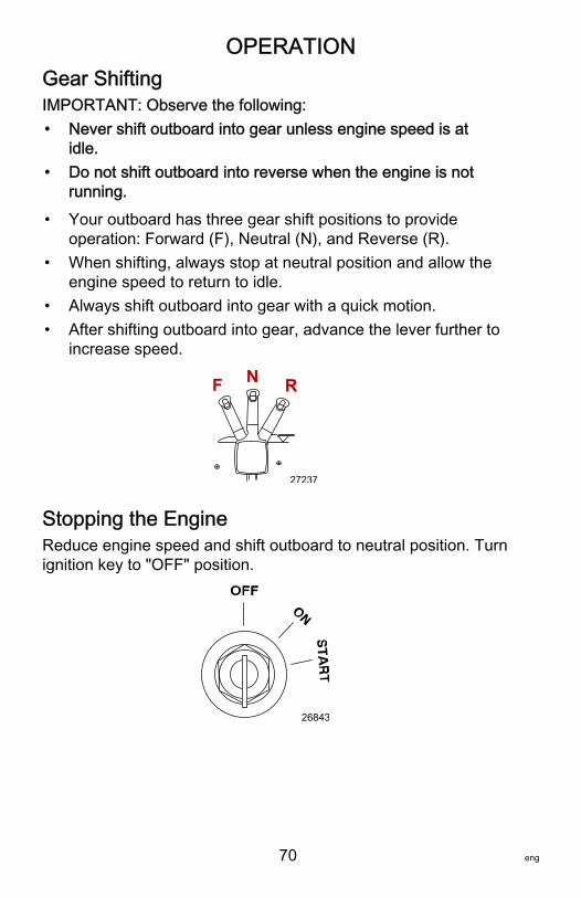
OPERATION
70 eng
Gear ShiftingIMPORTANT: Observe the following:• Never shift outboard into gear unless engine speed is at
idle.• Do not shift outboard into reverse when the engine is not
running.
• Your outboard has three gear shift positions to provideoperation: Forward (F), Neutral (N), and Reverse (R).
• When shifting, always stop at neutral position and allow theengine speed to return to idle.
• Always shift outboard into gear with a quick motion.• After shifting outboard into gear, advance the lever further to
increase speed.
N RF
27237
Stopping the EngineReduce engine speed and shift outboard to neutral position. Turnignition key to "OFF" position.
26843
MAINTENANCE
eng 71
Outboard CareTo keep your outboard in the best operating condition, it isimportant that your outboard receive the periodic inspections andmaintenance listed in the Inspection and MaintenanceSchedule. We urge you to keep it maintained properly to ensurethe safety of you and your passengers, and retain itsdependability.Record maintenance performed in the Maintenance Log at theback of this book. Save all maintenance work orders andreceipts.
SELECTING REPLACEMENT PARTS FOR YOUROUTBOARDWe recommend using original Mercury Precision or Quicksilverreplacement parts and Genuine Lubricants.
EPA Emissions RegulationsAll new outboards manufactured by Mercury Marine are certifiedto the United States Environmental Protection Agency, asconforming to the requirements of the regulations for the controlof air pollution from new outboard motors. This certification iscontingent on certain adjustments set to factory standards. Forthis reason, the factory procedure for servicing the product mustbe strictly followed and, wherever practicable, returned to theoriginal intent of the design. Maintenance, replacement, or repairof the emission control devices and systems may be performedby any marine spark ignition (SI) engine repair establishment orindividual.
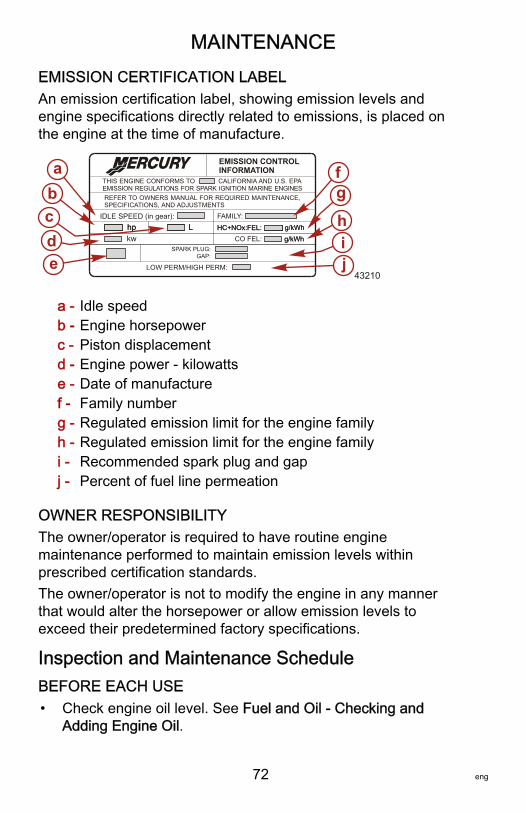
MAINTENANCE
72 eng
EMISSION CERTIFICATION LABELAn emission certification label, showing emission levels andengine specifications directly related to emissions, is placed onthe engine at the time of manufacture.
a - Idle speedb - Engine horsepowerc - Piston displacementd - Engine power ‑ kilowattse - Date of manufacturef - Family numberg - Regulated emission limit for the engine familyh - Regulated emission limit for the engine familyi - Recommended spark plug and gapj - Percent of fuel line permeation
OWNER RESPONSIBILITYThe owner/operator is required to have routine enginemaintenance performed to maintain emission levels withinprescribed certification standards.The owner/operator is not to modify the engine in any mannerthat would alter the horsepower or allow emission levels toexceed their predetermined factory specifications.
Inspection and Maintenance ScheduleBEFORE EACH USE• Check engine oil level. See Fuel and Oil ‑ Checking and
Adding Engine Oil.
SPARK PLUG:GAP:
EMISSION CONTROLINFORMATION
THIS ENGINE CONFORMS TOEMISSION REGULATIONS FOR SPARK IGNITION MARINE ENGINES
CALIFORNIA AND U.S. EPA
REFER TO OWNERS MANUAL FOR REQUIRED MAINTENANCE,SPECIFICATIONS, AND ADJUSTMENTS
IDLE SPEED (in gear): FAMILY:
HC+NOx:FEL:
LOW PERM/HIGH PERM:
g/kWhhp L
edcba f
g
hi
HC+NOx:FEL: g/kWhhp LCO FEL: g/kWhkw g/kWh
j43210
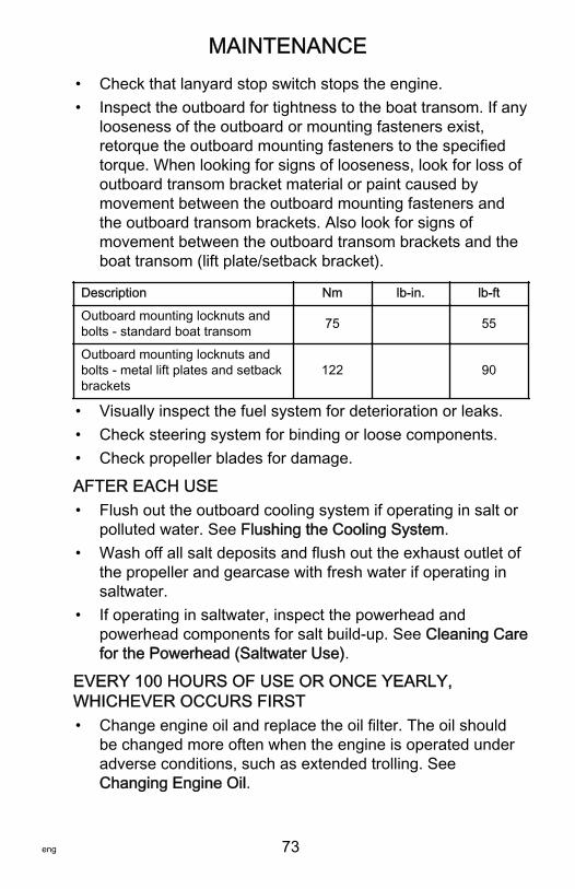
MAINTENANCE
eng 73
• Check that lanyard stop switch stops the engine.• Inspect the outboard for tightness to the boat transom. If any
looseness of the outboard or mounting fasteners exist,retorque the outboard mounting fasteners to the specifiedtorque. When looking for signs of looseness, look for loss ofoutboard transom bracket material or paint caused bymovement between the outboard mounting fasteners andthe outboard transom brackets. Also look for signs ofmovement between the outboard transom brackets and theboat transom (lift plate/setback bracket).
Description Nm lb‑in. lb‑ft
Outboard mounting locknuts andbolts ‑ standard boat transom 75 55
Outboard mounting locknuts andbolts ‑ metal lift plates and setbackbrackets
122 90
• Visually inspect the fuel system for deterioration or leaks.• Check steering system for binding or loose components.• Check propeller blades for damage.
AFTER EACH USE• Flush out the outboard cooling system if operating in salt or
polluted water. See Flushing the Cooling System.• Wash off all salt deposits and flush out the exhaust outlet of
the propeller and gearcase with fresh water if operating insaltwater.
• If operating in saltwater, inspect the powerhead andpowerhead components for salt build‑up. See Cleaning Carefor the Powerhead (Saltwater Use).
EVERY 100 HOURS OF USE OR ONCE YEARLY,WHICHEVER OCCURS FIRST• Change engine oil and replace the oil filter. The oil should
be changed more often when the engine is operated underadverse conditions, such as extended trolling. SeeChanging Engine Oil.
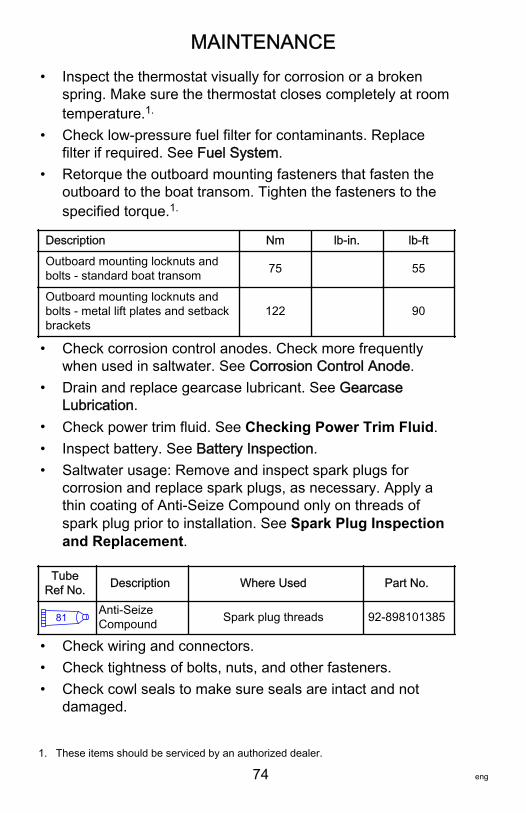
MAINTENANCE
74 eng
• Inspect the thermostat visually for corrosion or a brokenspring. Make sure the thermostat closes completely at roomtemperature.1.
• Check low‑pressure fuel filter for contaminants. Replacefilter if required. See Fuel System.
• Retorque the outboard mounting fasteners that fasten theoutboard to the boat transom. Tighten the fasteners to thespecified torque.1.
Description Nm lb‑in. lb‑ft
Outboard mounting locknuts andbolts ‑ standard boat transom 75 55
Outboard mounting locknuts andbolts ‑ metal lift plates and setbackbrackets
122 90
• Check corrosion control anodes. Check more frequentlywhen used in saltwater. See Corrosion Control Anode.
• Drain and replace gearcase lubricant. See GearcaseLubrication.
• Check power trim fluid. See Checking Power Trim Fluid.• Inspect battery. See Battery Inspection.• Saltwater usage: Remove and inspect spark plugs for
corrosion and replace spark plugs, as necessary. Apply athin coating of Anti‑Seize Compound only on threads ofspark plug prior to installation. See Spark Plug Inspectionand Replacement.
TubeRef No. Description Where Used Part No.
81 Anti-SeizeCompound Spark plug threads 92-898101385
• Check wiring and connectors.• Check tightness of bolts, nuts, and other fasteners.• Check cowl seals to make sure seals are intact and not
damaged.
1. These items should be serviced by an authorized dealer.
MAINTENANCE
eng 75
• Check internal cowl sound reduction foam (if equipped) tomake sure foam is intact and not damaged.
• Check that the intake silencer (if equipped) is in place.• Check that the idle relief muffler (if equipped) is in place.• Check for loose hose clamps and rubber boots (if equipped)
on the air intake assembly.
EVERY 300 HOURS OF USE OR THREE YEARS• Replace water pump impeller (more often if overheating
occurs or reduced water pressure is noted).1.
• Replace high‑pressure in‑line fuel filter.1.
• Replace spark plugs after the first 300 hours or three years.After that, inspect spark plugs every 300 hours or threeyears. Replace spark plugs as needed. See Spark PlugInspection and Replacement.
• Replace accessory drive belt. See Accessory Drive BeltInspection.1.
BEFORE PERIODS OF STORAGE• See Storage section.
Flushing the Cooling SystemFlush the internal water passages of the outboard with freshwater after each use in salt, polluted, or muddy water. This willhelp prevent a build‑up of deposits from clogging the internalwater passages.IMPORTANT: The engine must be run during flushing in order toopen the thermostat and circulate water through the waterpassages.NOTE: You can have the outboard tilted or in the verticaloperating position during flushing.
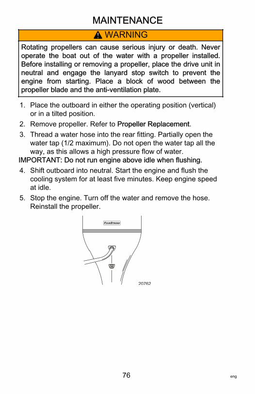
MAINTENANCE
76 eng
! WARNINGRotating propellers can cause serious injury or death. Neveroperate the boat out of the water with a propeller installed.Before installing or removing a propeller, place the drive unit inneutral and engage the lanyard stop switch to prevent theengine from starting. Place a block of wood between thepropeller blade and the anti‑ventilation plate.
1. Place the outboard in either the operating position (vertical)or in a tilted position.
2. Remove propeller. Refer to Propeller Replacement.3. Thread a water hose into the rear fitting. Partially open the
water tap (1/2 maximum). Do not open the water tap all theway, as this allows a high pressure flow of water.
IMPORTANT: Do not run engine above idle when flushing.4. Shift outboard into neutral. Start the engine and flush the
cooling system for at least five minutes. Keep engine speedat idle.
5. Stop the engine. Turn off the water and remove the hose.Reinstall the propeller.
OUR TRF S OKE
20762

MAINTENANCE
eng 77
Top Cowl Removal and InstallationREMOVAL1. Pull out the front cowl latch.
20739
2. Pull down the rear cowl latch. Remove the top cowl.
20741
INSTALLATION1. Lower the top cowl into position over the engine.2. Pull up the rear cowl latch to lock down the rear. Push in the
front cowl latch to lock down the front.
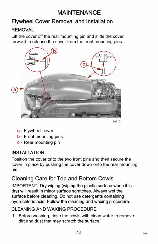
MAINTENANCE
78 eng
Flywheel Cover Removal and InstallationREMOVALLift the cover off the rear mounting pin and slide the coverforward to release the cover from the front mounting pins.
a - Flywheel coverb - Front mounting pinsc - Rear mounting pin
INSTALLATIONPosition the cover onto the two front pins and then secure thecover in place by pushing the cover down onto the rear mountingpin.
Cleaning Care for Top and Bottom CowlsIMPORTANT: Dry wiping (wiping the plastic surface when it isdry) will result in minor surface scratches. Always wet thesurface before cleaning. Do not use detergents containinghydrochloric acid. Follow the cleaning and waxing procedure.
CLEANING AND WAXING PROCEDURE1. Before washing, rinse the cowls with clean water to remove
dirt and dust that may scratch the surface.
20910
a
b
c
MAINTENANCE
eng 79
2. Wash the cowls with clean water and a mild nonabrasivesoap. Use a soft clean cloth when washing.
3. Dry thoroughly with a soft clean cloth.4. Wax the surface using a nonabrasive automotive polish
(polish designed for clear coat finishes). Remove the appliedwax by hand using a clean soft cloth.
5. To remove minor scratches, use Mercury Marine CowlFinishing Compound (92‑859026K 1).
Cleaning Care for the Powerhead (Saltwater Use)If the outboard is operated in saltwater, remove the top cowl andflywheel cover. Inspect the powerhead and powerheadcomponents for salt buildup. Wash off any salt buildup from thepowerhead and powerhead components with fresh water. Keepwater spray out of the air filter/intake and alternator. Afterwashing, allow the powerhead and components to dry. ApplyQuicksilver or Mercury Precision Lubricants Corrosion Guardspray on the external metal surfaces of the powerhead andpowerhead components. Do not allow the Corrosion Guard sprayto come in contact with the alternator drive belt or belt pulleys.IMPORTANT: Do not allow lubricant or Corrosion Guard spray tocome in contact with the alternator drive belt or the belt pulleys.The alternator drive belt could slip and be damaged if it becomescoated with any lubricant or Corrosion Guard spray.
Tube RefNo. Description Where Used Part No.
120 Corrosion GuardExternal metal surfaces of thepowerhead and powerhead
components.92-802878 55
Battery InspectionThe battery should be inspected at periodic intervals to ensureproper engine starting capability.IMPORTANT: Read the safety and maintenance instructionswhich accompany your battery.1. Turn off the engine before servicing the battery.
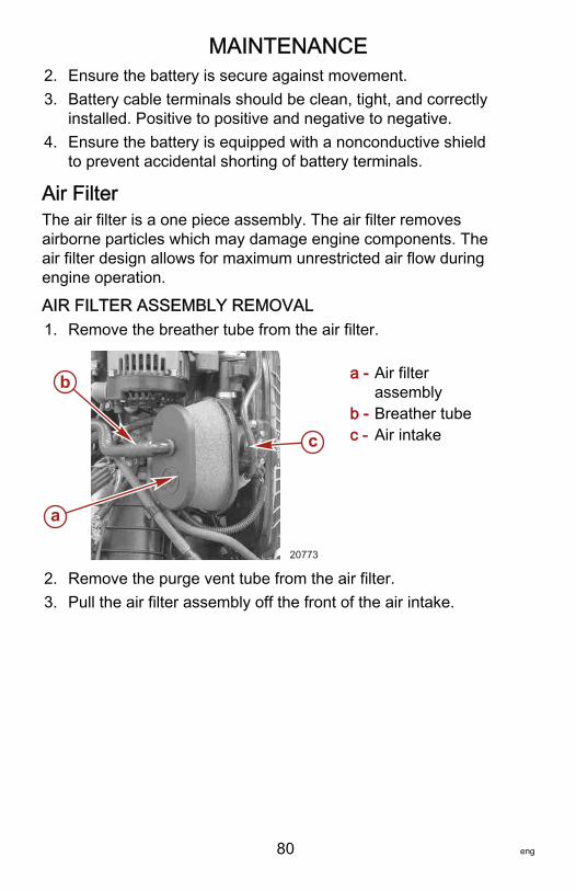
MAINTENANCE
80 eng
2. Ensure the battery is secure against movement.3. Battery cable terminals should be clean, tight, and correctly
installed. Positive to positive and negative to negative.4. Ensure the battery is equipped with a nonconductive shield
to prevent accidental shorting of battery terminals.
Air FilterThe air filter is a one piece assembly. The air filter removesairborne particles which may damage engine components. Theair filter design allows for maximum unrestricted air flow duringengine operation.
AIR FILTER ASSEMBLY REMOVAL1. Remove the breather tube from the air filter.
a - Air filterassembly
b - Breather tubec - Air intake
2. Remove the purge vent tube from the air filter.3. Pull the air filter assembly off the front of the air intake.
a
b
20773
c
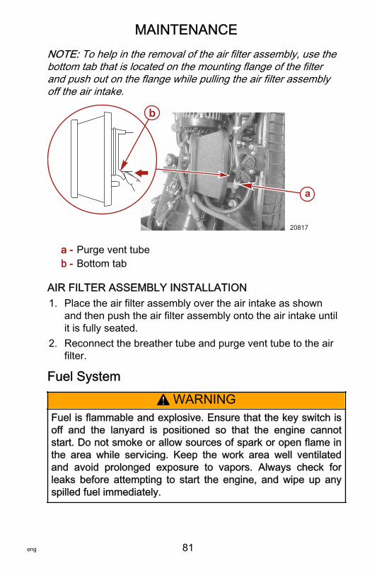
MAINTENANCE
eng 81
NOTE: To help in the removal of the air filter assembly, use thebottom tab that is located on the mounting flange of the filterand push out on the flange while pulling the air filter assemblyoff the air intake.
a - Purge vent tubeb - Bottom tab
AIR FILTER ASSEMBLY INSTALLATION1. Place the air filter assembly over the air intake as shown
and then push the air filter assembly onto the air intake untilit is fully seated.
2. Reconnect the breather tube and purge vent tube to the airfilter.
Fuel System
! WARNINGFuel is flammable and explosive. Ensure that the key switch isoff and the lanyard is positioned so that the engine cannotstart. Do not smoke or allow sources of spark or open flame inthe area while servicing. Keep the work area well ventilatedand avoid prolonged exposure to vapors. Always check forleaks before attempting to start the engine, and wipe up anyspilled fuel immediately.
a
20817
b
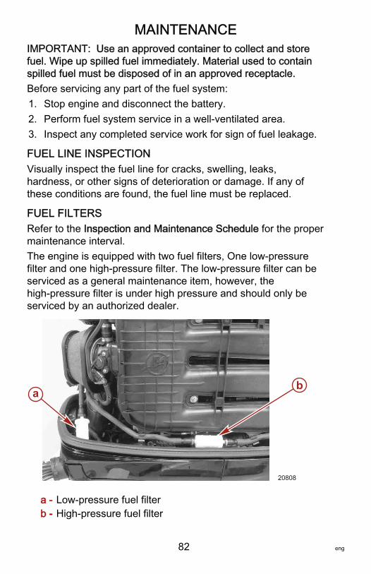
MAINTENANCE
82 eng
IMPORTANT: Use an approved container to collect and storefuel. Wipe up spilled fuel immediately. Material used to containspilled fuel must be disposed of in an approved receptacle.Before servicing any part of the fuel system:1. Stop engine and disconnect the battery.2. Perform fuel system service in a well‑ventilated area.3. Inspect any completed service work for sign of fuel leakage.
FUEL LINE INSPECTIONVisually inspect the fuel line for cracks, swelling, leaks,hardness, or other signs of deterioration or damage. If any ofthese conditions are found, the fuel line must be replaced.
FUEL FILTERSRefer to the Inspection and Maintenance Schedule for the propermaintenance interval.The engine is equipped with two fuel filters, One low‑pressurefilter and one high‑pressure filter. The low‑pressure filter can beserviced as a general maintenance item, however, thehigh‑pressure filter is under high pressure and should only beserviced by an authorized dealer.
a - Low‑pressure fuel filterb - High‑pressure fuel filter
ab
20808
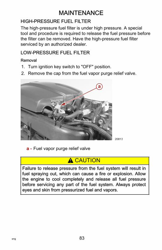
MAINTENANCE
eng 83
HIGH-PRESSURE FUEL FILTERThe high‑pressure fuel filter is under high pressure. A specialtool and procedure is required to release the fuel pressure beforethe filter can be removed. Have the high‑pressure fuel filterserviced by an authorized dealer.
LOW-PRESSURE FUEL FILTERRemoval1. Turn ignition key switch to "OFF" position.2. Remove the cap from the fuel vapor purge relief valve.
a - Fuel vapor purge relief valve
! CAUTIONFailure to release pressure from the fuel system will result infuel spraying out, which can cause a fire or explosion. Allowthe engine to cool completely and release all fuel pressurebefore servicing any part of the fuel system. Always protecteyes and skin from pressurized fuel and vapors.
a
20813
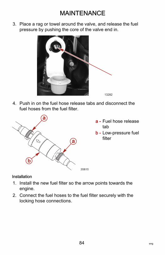
MAINTENANCE
84 eng
3. Place a rag or towel around the valve, and release the fuelpressure by pushing the core of the valve end in.
13282
4. Push in on the fuel hose release tabs and disconnect thefuel hoses from the fuel filter.
a - Fuel hose releasetab
b - Low‑pressure fuelfilter
Installation1. Install the new fuel filter so the arrow points towards the
engine.2. Connect the fuel hoses to the fuel filter securely with the
locking hose connections.
a
a
20815
b
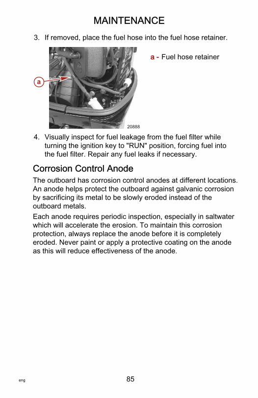
MAINTENANCE
eng 85
3. If removed, place the fuel hose into the fuel hose retainer.
a - Fuel hose retainer
4. Visually inspect for fuel leakage from the fuel filter whileturning the ignition key to "RUN" position, forcing fuel intothe fuel filter. Repair any fuel leaks if necessary.
Corrosion Control AnodeThe outboard has corrosion control anodes at different locations.An anode helps protect the outboard against galvanic corrosionby sacrificing its metal to be slowly eroded instead of theoutboard metals.Each anode requires periodic inspection, especially in saltwaterwhich will accelerate the erosion. To maintain this corrosionprotection, always replace the anode before it is completelyeroded. Never paint or apply a protective coating on the anodeas this will reduce effectiveness of the anode.
a
20888
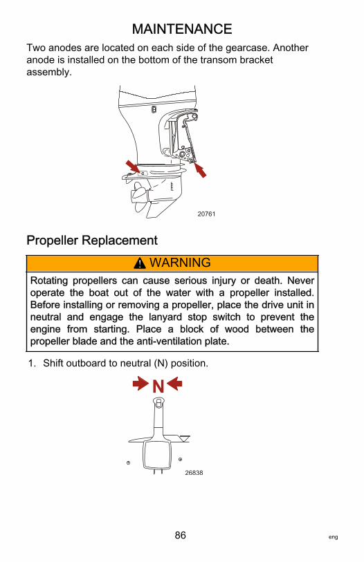
MAINTENANCE
86 eng
Two anodes are located on each side of the gearcase. Anotheranode is installed on the bottom of the transom bracketassembly.
20761
Propeller Replacement
! WARNINGRotating propellers can cause serious injury or death. Neveroperate the boat out of the water with a propeller installed.Before installing or removing a propeller, place the drive unit inneutral and engage the lanyard stop switch to prevent theengine from starting. Place a block of wood between thepropeller blade and the anti‑ventilation plate.
1. Shift outboard to neutral (N) position.
N
26838
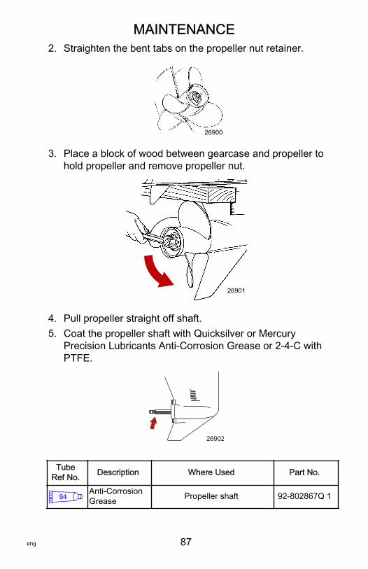
MAINTENANCE
eng 87
2. Straighten the bent tabs on the propeller nut retainer.
26900
3. Place a block of wood between gearcase and propeller tohold propeller and remove propeller nut.
26901
4. Pull propeller straight off shaft.5. Coat the propeller shaft with Quicksilver or Mercury
Precision Lubricants Anti‑Corrosion Grease or 2‑4‑C withPTFE.
26902
TubeRef No. Description Where Used Part No.
94Anti-CorrosionGrease Propeller shaft 92-802867Q 1
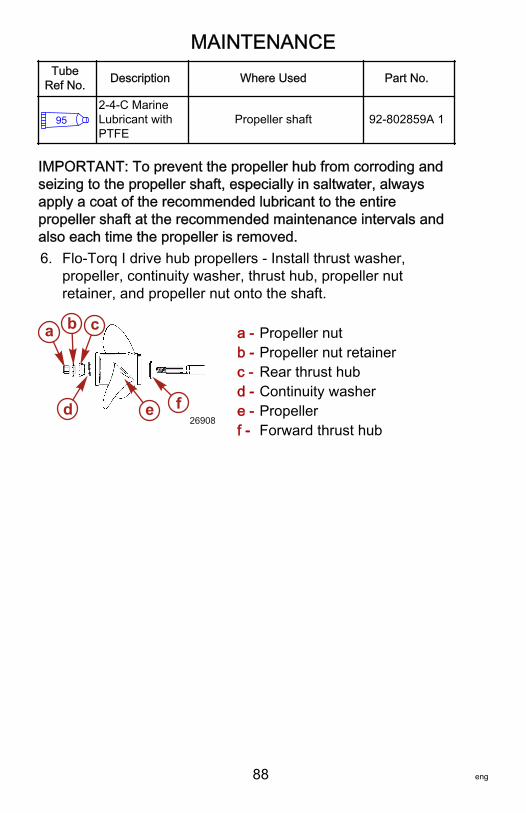
MAINTENANCE
88 eng
TubeRef No. Description Where Used Part No.
952-4-C MarineLubricant withPTFE
Propeller shaft 92-802859A 1
IMPORTANT: To prevent the propeller hub from corroding andseizing to the propeller shaft, especially in saltwater, alwaysapply a coat of the recommended lubricant to the entirepropeller shaft at the recommended maintenance intervals andalso each time the propeller is removed.6. Flo‑Torq I drive hub propellers ‑ Install thrust washer,
propeller, continuity washer, thrust hub, propeller nutretainer, and propeller nut onto the shaft.
a - Propeller nutb - Propeller nut retainerc - Rear thrust hubd - Continuity washere - Propellerf - Forward thrust hub
a b c
d e f26908
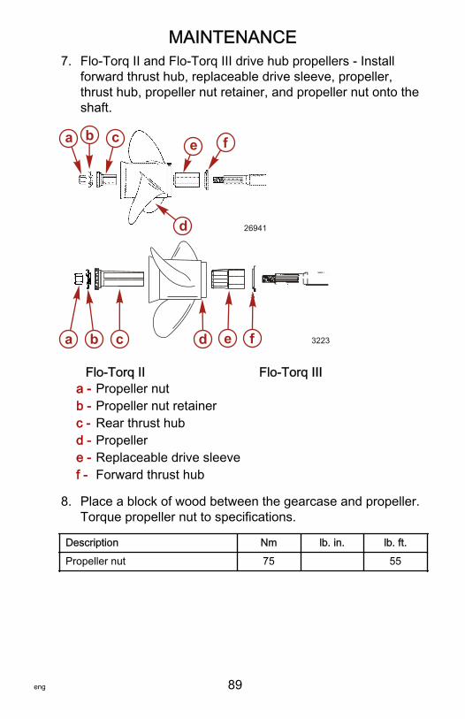
MAINTENANCE
eng 89
7. Flo‑Torq II and Flo‑Torq III drive hub propellers ‑ Installforward thrust hub, replaceable drive sleeve, propeller,thrust hub, propeller nut retainer, and propeller nut onto theshaft.
Flo-Torq II Flo-Torq IIIa - Propeller nutb - Propeller nut retainerc - Rear thrust hubd - Propellere - Replaceable drive sleevef - Forward thrust hub
8. Place a block of wood between the gearcase and propeller.Torque propeller nut to specifications.
Description Nm lb. in. lb. ft.
Propeller nut 75 55
a b c
d
e f
26941
3223a b c d e f
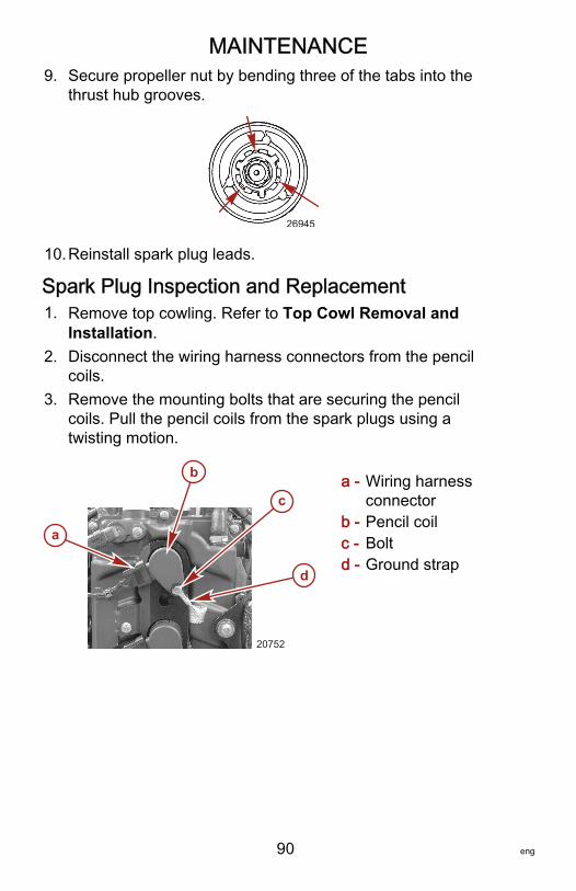
MAINTENANCE
90 eng
9. Secure propeller nut by bending three of the tabs into thethrust hub grooves.
26945
10.Reinstall spark plug leads.
Spark Plug Inspection and Replacement1. Remove top cowling. Refer to Top Cowl Removal and
Installation.2. Disconnect the wiring harness connectors from the pencil
coils.3. Remove the mounting bolts that are securing the pencil
coils. Pull the pencil coils from the spark plugs using atwisting motion.
a - Wiring harnessconnector
b - Pencil coilc - Boltd - Ground strap
a
b
d
c
20752
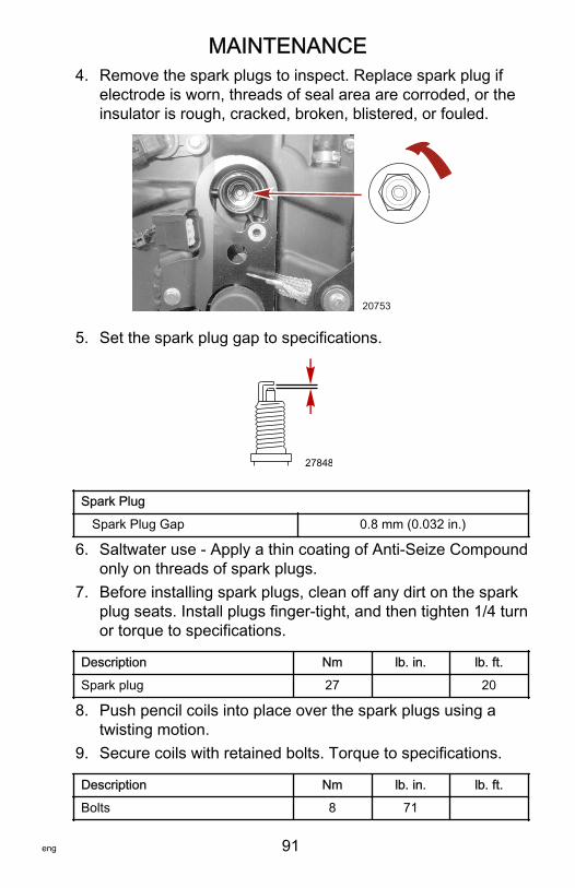
MAINTENANCE
eng 91
4. Remove the spark plugs to inspect. Replace spark plug ifelectrode is worn, threads of seal area are corroded, or theinsulator is rough, cracked, broken, blistered, or fouled.
20753
5. Set the spark plug gap to specifications.
27848
Spark Plug
Spark Plug Gap 0.8 mm (0.032 in.)
6. Saltwater use ‑ Apply a thin coating of Anti‑Seize Compoundonly on threads of spark plugs.
7. Before installing spark plugs, clean off any dirt on the sparkplug seats. Install plugs finger‑tight, and then tighten 1/4 turnor torque to specifications.
Description Nm lb. in. lb. ft.
Spark plug 27 20
8. Push pencil coils into place over the spark plugs using atwisting motion.
9. Secure coils with retained bolts. Torque to specifications.
Description Nm lb. in. lb. ft.
Bolts 8 71
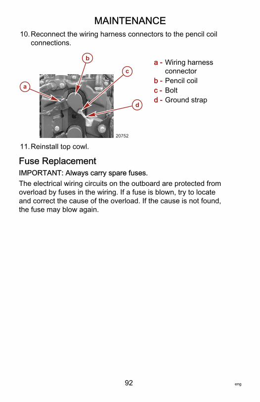
MAINTENANCE
92 eng
10.Reconnect the wiring harness connectors to the pencil coilconnections.
a - Wiring harnessconnector
b - Pencil coilc - Boltd - Ground strap
11.Reinstall top cowl.
Fuse ReplacementIMPORTANT: Always carry spare fuses.The electrical wiring circuits on the outboard are protected fromoverload by fuses in the wiring. If a fuse is blown, try to locateand correct the cause of the overload. If the cause is not found,the fuse may blow again.
a
b
d
c
20752
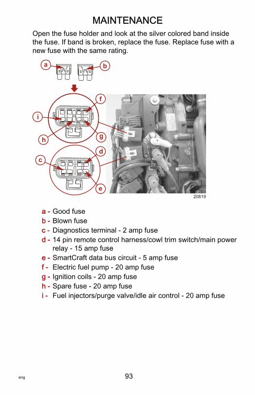
MAINTENANCE
eng 93
Open the fuse holder and look at the silver colored band insidethe fuse. If band is broken, replace the fuse. Replace fuse with anew fuse with the same rating.
a - Good fuseb - Blown fusec - Diagnostics terminal ‑ 2 amp fused - 14 pin remote control harness/cowl trim switch/main power
relay ‑ 15 amp fusee - SmartCraft data bus circuit ‑ 5 amp fusef - Electric fuel pump ‑ 20 amp fuseg - Ignition coils ‑ 20 amp fuseh - Spare fuse ‑ 20 amp fusei - Fuel injectors/purge valve/idle air control ‑ 20 amp fuse
a b
52
15c
d
e
2020
20
20
f
gh
i
20819
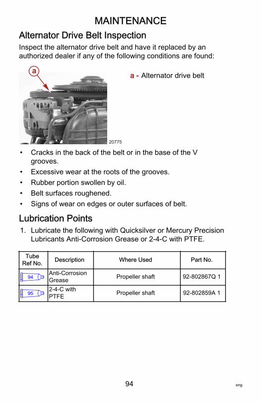
MAINTENANCE
94 eng
Alternator Drive Belt InspectionInspect the alternator drive belt and have it replaced by anauthorized dealer if any of the following conditions are found:
a - Alternator drive belt
• Cracks in the back of the belt or in the base of the Vgrooves.
• Excessive wear at the roots of the grooves.• Rubber portion swollen by oil.• Belt surfaces roughened.• Signs of wear on edges or outer surfaces of belt.
Lubrication Points1. Lubricate the following with Quicksilver or Mercury Precision
Lubricants Anti‑Corrosion Grease or 2‑4‑C with PTFE.
TubeRef No. Description Where Used Part No.
94Anti-CorrosionGrease Propeller shaft 92-802867Q 1
952-4-C withPTFE Propeller shaft 92-802859A 1
a
20775
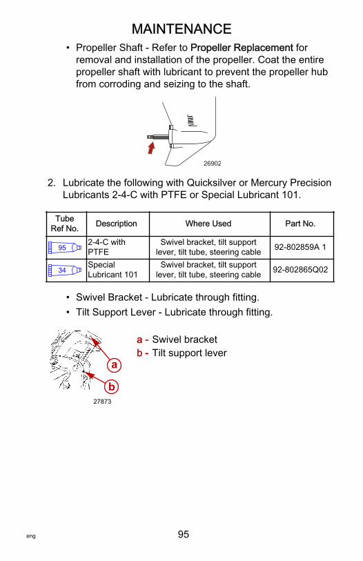
MAINTENANCE
eng 95
• Propeller Shaft ‑ Refer to Propeller Replacement forremoval and installation of the propeller. Coat the entirepropeller shaft with lubricant to prevent the propeller hubfrom corroding and seizing to the shaft.
26902
2. Lubricate the following with Quicksilver or Mercury PrecisionLubricants 2‑4‑C with PTFE or Special Lubricant 101.
TubeRef No. Description Where Used Part No.
952-4-C withPTFE
Swivel bracket, tilt supportlever, tilt tube, steering cable 92-802859A 1
34SpecialLubricant 101
Swivel bracket, tilt supportlever, tilt tube, steering cable 92-802865Q02
• Swivel Bracket ‑ Lubricate through fitting.• Tilt Support Lever ‑ Lubricate through fitting.
a - Swivel bracketb - Tilt support lever
a
b27873
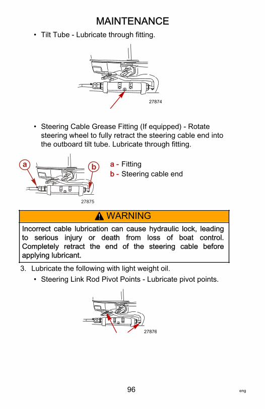
MAINTENANCE
96 eng
• Tilt Tube ‑ Lubricate through fitting.
27874
• Steering Cable Grease Fitting (If equipped) ‑ Rotatesteering wheel to fully retract the steering cable end intothe outboard tilt tube. Lubricate through fitting.
a - Fittingb - Steering cable end
! WARNINGIncorrect cable lubrication can cause hydraulic lock, leadingto serious injury or death from loss of boat control.Completely retract the end of the steering cable beforeapplying lubricant.
3. Lubricate the following with light weight oil.• Steering Link Rod Pivot Points ‑ Lubricate pivot points.
27876
a b
27875
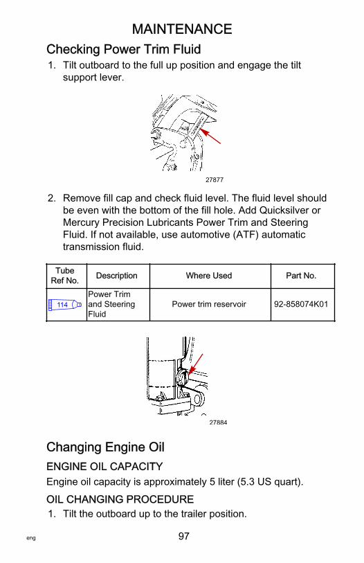
MAINTENANCE
eng 97
Checking Power Trim Fluid1. Tilt outboard to the full up position and engage the tilt
support lever.
27877
2. Remove fill cap and check fluid level. The fluid level shouldbe even with the bottom of the fill hole. Add Quicksilver orMercury Precision Lubricants Power Trim and SteeringFluid. If not available, use automotive (ATF) automatictransmission fluid.
TubeRef No. Description Where Used Part No.
114Power Trimand SteeringFluid
Power trim reservoir 92-858074K01
27884
Changing Engine OilENGINE OIL CAPACITYEngine oil capacity is approximately 5 liter (5.3 US quart).
OIL CHANGING PROCEDURE1. Tilt the outboard up to the trailer position.
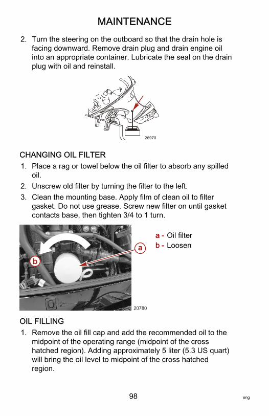
MAINTENANCE
98 eng
2. Turn the steering on the outboard so that the drain hole isfacing downward. Remove drain plug and drain engine oilinto an appropriate container. Lubricate the seal on the drainplug with oil and reinstall.
26970
CHANGING OIL FILTER1. Place a rag or towel below the oil filter to absorb any spilled
oil.2. Unscrew old filter by turning the filter to the left.3. Clean the mounting base. Apply film of clean oil to filter
gasket. Do not use grease. Screw new filter on until gasketcontacts base, then tighten 3/4 to 1 turn.
a - Oil filterb - Loosen
OIL FILLING1. Remove the oil fill cap and add the recommended oil to the
midpoint of the operating range (midpoint of the crosshatched region). Adding approximately 5 liter (5.3 US quart)will bring the oil level to midpoint of the cross hatchedregion.
ab
20780
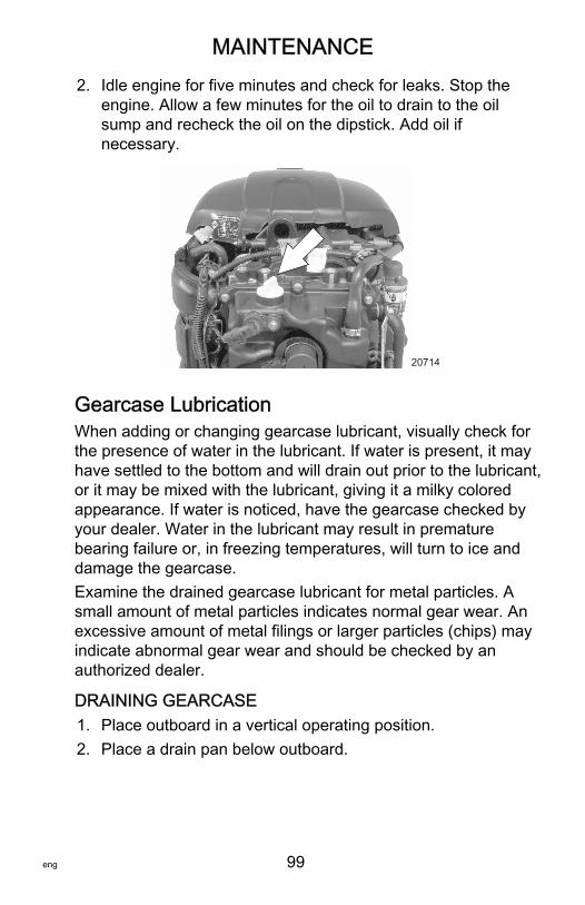
MAINTENANCE
eng 99
2. Idle engine for five minutes and check for leaks. Stop theengine. Allow a few minutes for the oil to drain to the oilsump and recheck the oil on the dipstick. Add oil ifnecessary.
20714
Gearcase LubricationWhen adding or changing gearcase lubricant, visually check forthe presence of water in the lubricant. If water is present, it mayhave settled to the bottom and will drain out prior to the lubricant,or it may be mixed with the lubricant, giving it a milky coloredappearance. If water is noticed, have the gearcase checked byyour dealer. Water in the lubricant may result in prematurebearing failure or, in freezing temperatures, will turn to ice anddamage the gearcase.Examine the drained gearcase lubricant for metal particles. Asmall amount of metal particles indicates normal gear wear. Anexcessive amount of metal filings or larger particles (chips) mayindicate abnormal gear wear and should be checked by anauthorized dealer.
DRAINING GEARCASE1. Place outboard in a vertical operating position.2. Place a drain pan below outboard.
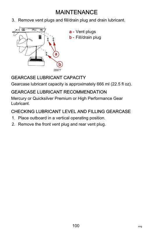
MAINTENANCE
100 eng
3. Remove vent plugs and fill/drain plug and drain lubricant.
a - Vent plugsb - Fill/drain plug
GEARCASE LUBRICANT CAPACITYGearcase lubricant capacity is approximately 666 ml (22.5 fl oz).
GEARCASE LUBRICANT RECOMMENDATIONMercury or Quicksilver Premium or High Performance GearLubricant.
CHECKING LUBRICANT LEVEL AND FILLING GEARCASE1. Place outboard in a vertical operating position.2. Remove the front vent plug and rear vent plug.
b
a
26977
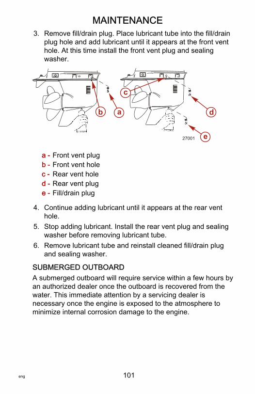
MAINTENANCE
eng 101
3. Remove fill/drain plug. Place lubricant tube into the fill/drainplug hole and add lubricant until it appears at the front venthole. At this time install the front vent plug and sealingwasher.
a - Front vent plugb - Front vent holec - Rear vent holed - Rear vent pluge - Fill/drain plug
4. Continue adding lubricant until it appears at the rear venthole.
5. Stop adding lubricant. Install the rear vent plug and sealingwasher before removing lubricant tube.
6. Remove lubricant tube and reinstall cleaned fill/drain plugand sealing washer.
SUBMERGED OUTBOARDA submerged outboard will require service within a few hours byan authorized dealer once the outboard is recovered from thewater. This immediate attention by a servicing dealer isnecessary once the engine is exposed to the atmosphere tominimize internal corrosion damage to the engine.
27001
b a
c
d
e
STORAGE
102 eng
Storage PreparationThe major consideration in preparing your outboard for storage isto protect it from rust, corrosion, and damage caused by freezingof trapped water.The following storage procedures should be followed to prepareyour outboard for out of season storage or prolonged storage(two months or longer).
NOTICEWithout sufficient cooling water, the engine, the water pump,and other components will overheat and suffer damage.Provide a sufficient supply of water to the water inlets duringoperation.
FUEL SYSTEMIMPORTANT: Gasoline containing alcohol (ethanol or methanol)can cause a formation of acid during storage and can damagethe fuel system. If the gasoline being used contains alcohol, it isadvisable to drain as much of the remaining gasoline as possiblefrom the fuel tank, remote fuel line, and engine fuel system.IMPORTANT: This outboard is equipped with a closed fuelsystem when the engine is not running. With this closed system,fuel within the engine's fuel system, other than the fuel tank, willremain stable during normal storage periods without the additionof fuel treatment stabilizers.Fill the fuel tank and engine fuel system with treated (stabilized)fuel to help prevent formation of varnish and gum. Proceed withthe following instructions.• Portable fuel tank ‑ Pour the required amount of Fuel
System Treatment and Stabilizer (follow instructions oncontainer) into fuel tank. Tip fuel tank back and forth to mixstabilizer with the fuel.
• Permanently installed fuel tank ‑ Pour the required amountof Fuel System Treatment and Stabilizer (follow instructionson container) into a separate container and mix withapproximately one liter (one quart) of gasoline. Pour thismixture into fuel tank.
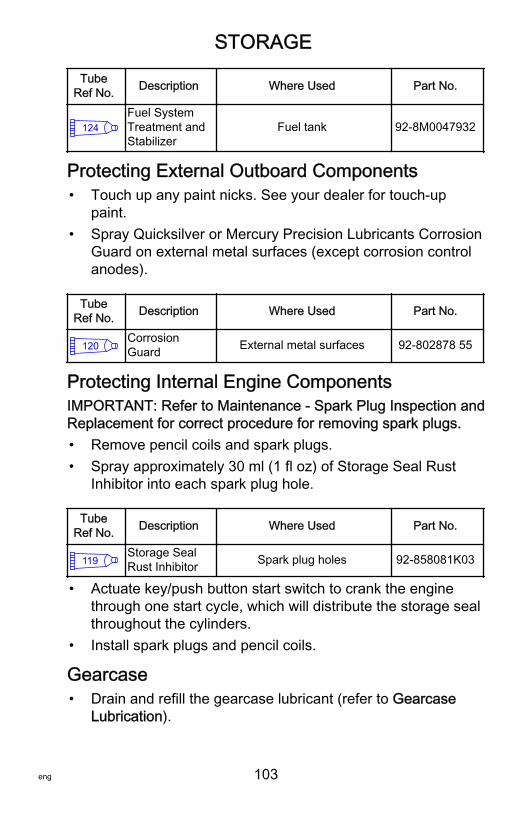
STORAGE
eng 103
TubeRef No. Description Where Used Part No.
124Fuel SystemTreatment andStabilizer
Fuel tank 92-8M0047932
Protecting External Outboard Components• Touch up any paint nicks. See your dealer for touch‑up
paint.• Spray Quicksilver or Mercury Precision Lubricants Corrosion
Guard on external metal surfaces (except corrosion controlanodes).
TubeRef No. Description Where Used Part No.
120CorrosionGuard External metal surfaces 92-802878 55
Protecting Internal Engine ComponentsIMPORTANT: Refer to Maintenance ‑ Spark Plug Inspection andReplacement for correct procedure for removing spark plugs.• Remove pencil coils and spark plugs.• Spray approximately 30 ml (1 fl oz) of Storage Seal Rust
Inhibitor into each spark plug hole.
TubeRef No. Description Where Used Part No.
119Storage SealRust Inhibitor Spark plug holes 92-858081K03
• Actuate key/push button start switch to crank the enginethrough one start cycle, which will distribute the storage sealthroughout the cylinders.
• Install spark plugs and pencil coils.
Gearcase• Drain and refill the gearcase lubricant (refer to Gearcase
Lubrication).
STORAGE
104 eng
Positioning Outboard for StorageStore outboard in an upright (vertical) position to allow water todrain out of the outboard.
NOTICEStoring the outboard in a tilted position can damage theoutboard. Water trapped in the cooling passages or rain watercollected in the propeller exhaust outlet in the gearcase canfreeze. Store the outboard in the full down position.
Battery Storage• Follow the battery manufacturer's instructions for storage
and recharging.• Remove the battery from the boat and check water level.
Recharge if necessary.• Store the battery in a cool, dry place.• Periodically check the water level and recharge the battery
during storage.
TROUBLESHOOTING
eng 105
Starter Motor Will Not Crank the EnginePOSSIBLE CAUSES• Lanyard stop switch not in "RUN" position.• Blown 15 amp fuse. Check 14 pin remote control harness/
cowl trim switch/main power relay fuse. Refer toMaintenance section.
• Outboard is not shifted to neutral position.• Weak battery or battery connections are loose or corroded.• Ignition key switch failure.• Wiring or electrical connection faulty.• Starter motor solenoid or slave solenoid failure.
Engine Will Not StartPOSSIBLE CAUSES• Incorrect starting procedure. Refer to Operation section.• Old or contaminated gasoline.• Fuel is not reaching the engine.
• Fuel tank is empty.• Fuel tank vent not open or restricted.• Fuel line is disconnected or kinked.• Fuel filter is obstructed. Refer to Maintenance section.• Fuel pump failure.• Fuel tank filter obstructed.
• Ignition system component failure.• Spark plugs fouled or defective. Refer to Maintenance
section.
Engine Runs ErraticallyPOSSIBLE CAUSES• Overheating ‑ Warning horn not working.• Low oil pressure. Check oil level.• Spark plugs fouled or defective. Refer to Maintenance
section.
TROUBLESHOOTING
106 eng
• Incorrect setup and adjustments.• Fuel is being restricted to the engine.
a. Engine fuel filter is obstructed. Refer to Maintenancesection.
b. Fuel tank filter obstructed.c. Stuck anti‑siphon valve located on permanently built‑in
type fuel tanks.d. Fuel line is kinked or pinched.
• Fuel pump failure.• Ignition system component failure.
Performance LossPOSSIBLE CAUSES• Overheating ‑ Warning horn not working.• Low oil pressure. Check oil level.• Throttle not opening fully.• Damaged propeller or improper propeller size.• Incorrect engine timing, adjustment, or setup.• Boat overloaded or load improperly distributed.• Excessive water in bilge.• Boat bottom is dirty or damaged.
Battery Will Not Hold ChargePOSSIBLE CAUSES• Battery connections are loose or corroded.• Low electrolyte level in battery.• Worn out or inefficient battery.• Excessive use of electrical accessories.• Defective rectifier, alternator, or voltage regulator.• Open circuit in the alternator output wire (fused link).
OWNER SERVICE ASSISTANCE
eng 107
Local Repair ServiceAlways return your outboard to your local authorized dealershould the need for service arise. Only he has the factory trainedmechanics, knowledge, special tools, equipment, and genuineparts and accessories to properly service your engine should theneed occur. He knows your engine best.
Service Away from HomeIf you are away from your local dealer and the need arises forservice, contact the nearest authorized dealer. Refer to theYellow Pages of the telephone directory. If, for any reason, youcannot obtain service, contact the nearest Mercury MarineService Office.
Parts and Accessories InquiriesAll inquiries concerning genuine replacement parts andaccessories should be directed to your local authorized dealer.The dealer has the necessary information to order parts andaccessories for you. When inquiring on parts and accessories,the dealer requires the model and serial number to order thecorrect parts.
Service AssistanceYour satisfaction with your outboard product is very important toyour dealer and to us. If you ever have a problem, question orconcern about your outboard product, contact your dealer or anyauthorized Mercury Marine dealership. If additional assistance isrequired, take these steps.1. Talk with the dealership's sales manager or service
manager. If this has already been done, then contact theowner of the dealership.
2. Should you have a question, concern, or problem thatcannot be resolved by your dealership, please contactMercury Marine Service Office for assistance. MercuryMarine will work with you and your dealership to resolve allproblems.
The following information will be needed by the service office:
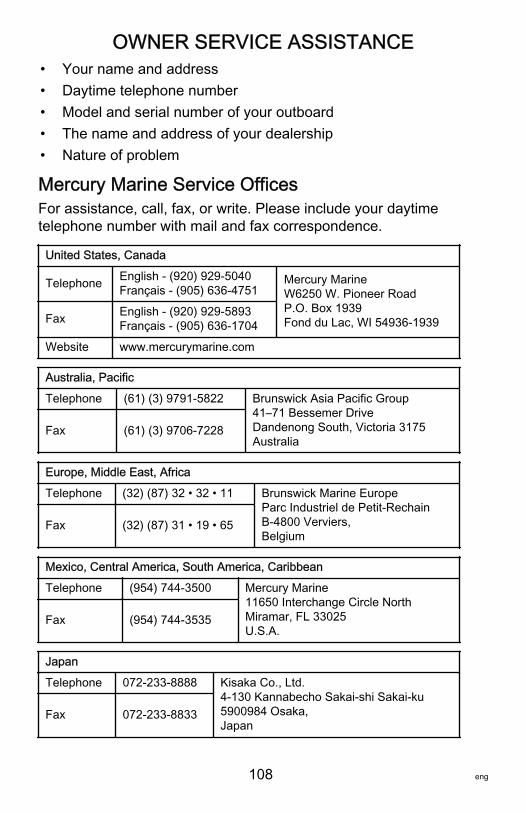
OWNER SERVICE ASSISTANCE
108 eng
• Your name and address• Daytime telephone number• Model and serial number of your outboard• The name and address of your dealership• Nature of problem
Mercury Marine Service OfficesFor assistance, call, fax, or write. Please include your daytimetelephone number with mail and fax correspondence.
United States, Canada
Telephone English ‑ (920) 929‑5040Français ‑ (905) 636‑4751
Mercury MarineW6250 W. Pioneer RoadP.O. Box 1939Fond du Lac, WI 54936-1939Fax English ‑ (920) 929‑5893
Français ‑ (905) 636‑1704
Website www.mercurymarine.com
Australia, Pacific
Telephone (61) (3) 9791‑5822 Brunswick Asia Pacific Group41–71 Bessemer DriveDandenong South, Victoria 3175Australia
Fax (61) (3) 9706‑7228
Europe, Middle East, Africa
Telephone (32) (87) 32 • 32 • 11 Brunswick Marine EuropeParc Industriel de Petit-RechainB-4800 Verviers,Belgium
Fax (32) (87) 31 • 19 • 65
Mexico, Central America, South America, Caribbean
Telephone (954) 744‑3500 Mercury Marine11650 Interchange Circle NorthMiramar, FL 33025U.S.A.
Fax (954) 744‑3535
Japan
Telephone 072‑233‑8888 Kisaka Co., Ltd.4-130 Kannabecho Sakai-shi Sakai-ku5900984 Osaka,Japan
Fax 072‑233‑8833
OWNER SERVICE ASSISTANCE
eng 109
Asia, Singapore
Telephone (65) 65466160 Brunswick Asia Pacific GroupT/A Mercury Marine Singapore Pte Ltd29 Loyang DriveSingapore, 508944
Fax (65) 65467789

OUTBOARD INSTALLATION
110 eng
Important InformationRigging boats, which includes proper engine installation hasbecome more complex over the years. As a result, MercuryMarine recommends that engines be installed only by Mercuryauthorized dealers. If you intend to disregard thisrecommendation, and install the engine yourself, please makesure to read and comply with these instructions. Failure tocomply with these installation instructions could lead to seriousinjury or death.NOTE: Do not install an accessory electric fuel pump or a fuelline primer bulb into the fuel system of this engine.
Boat Horsepower Capacity
! WARNINGExceeding the boat's maximum horsepower rating can causeserious injury or death. Overpowering the boat can affect boatcontrol and flotation characteristics or break the transom. Donot install an engine that exceeds the boat's maximum powerrating.
Do not overpower or overload your boat. Most boats will carry arequired capacity plate indicating the maximum acceptablepower and load as determined by the manufacturer followingcertain federal guidelines. If in doubt, contact your dealer or theboat manufacturer.
U.S. COAST GUARD CAPACITYMAXIMUM HORSEPOWER XXXMAXIMUM PERSON CAPACITY (POUNDS) XXXMAXIMUM WEIGHT CAPACITY XXX
26777
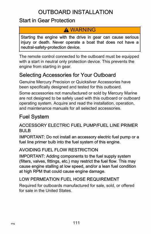
OUTBOARD INSTALLATION
eng 111
Start in Gear Protection
! WARNINGStarting the engine with the drive in gear can cause seriousinjury or death. Never operate a boat that does not have aneutral‑safety‑protection device.
The remote control connected to the outboard must be equippedwith a start in neutral only protection device. This prevents theengine from starting in gear.
Selecting Accessories for Your OutboardGenuine Mercury Precision or Quicksilver Accessories havebeen specifically designed and tested for this outboard.Some accessories not manufactured or sold by Mercury Marineare not designed to be safely used with this outboard or outboardoperating system. Acquire and read the installation, operation,and maintenance manuals for all selected accessories.
Fuel SystemACCESSORY ELECTRIC FUEL PUMP/FUEL LINE PRIMERBULBIMPORTANT: Do not install an accessory electric fuel pump or afuel line primer bulb into the fuel system of this engine.
AVOIDING FUEL FLOW RESTRICTIONIMPORTANT: Adding components to the fuel supply system(filters, valves, fittings, etc.) may restrict the fuel flow. This maycause engine stalling at low speed, and/or a lean fuel conditionat high RPM that could cause engine damage.
LOW PERMEATION FUEL HOSE REQUIREMENTRequired for outboards manufactured for sale, sold, or offeredfor sale in the United States.
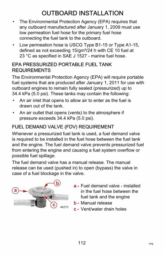
OUTBOARD INSTALLATION
112 eng
• The Environmental Protection Agency (EPA) requires thatany outboard manufactured after January 1, 2009 must uselow permeation fuel hose for the primary fuel hoseconnecting the fuel tank to the outboard.
• Low permeation hose is USCG Type B1‑15 or Type A1‑15,defined as not exceeding 15/gm²/24 h with CE 10 fuel at23 °C as specified in SAE J 1527 ‑ marine fuel hose.
EPA PRESSURIZED PORTABLE FUEL TANKREQUIREMENTSThe Environmental Protection Agency (EPA) will require portablefuel systems that are produced after January 1, 2011 for use withoutboard engines to remain fully sealed (pressurized) up to34.4 kPa (5.0 psi). These tanks may contain the following:• An air inlet that opens to allow air to enter as the fuel is
drawn out of the tank.• An air outlet that opens (vents) to the atmosphere if
pressure exceeds 34.4 kPa (5.0 psi).
FUEL DEMAND VALVE (FDV) REQUIREMENTWhenever a pressurized fuel tank is used, a fuel demand valveis required to be installed in the fuel hose between the fuel tankand the engine. The fuel demand valve prevents pressurized fuelfrom entering the engine and causing a fuel system overflow orpossible fuel spillage.The fuel demand valve has a manual release. The manualrelease can be used (pushed in) to open (bypass) the valve incase of a fuel blockage in the valve.
a - Fuel demand valve ‑ installedin the fuel hose between thefuel tank and the engine
b - Manual releasec - Vent/water drain holes
a
c
b
46273
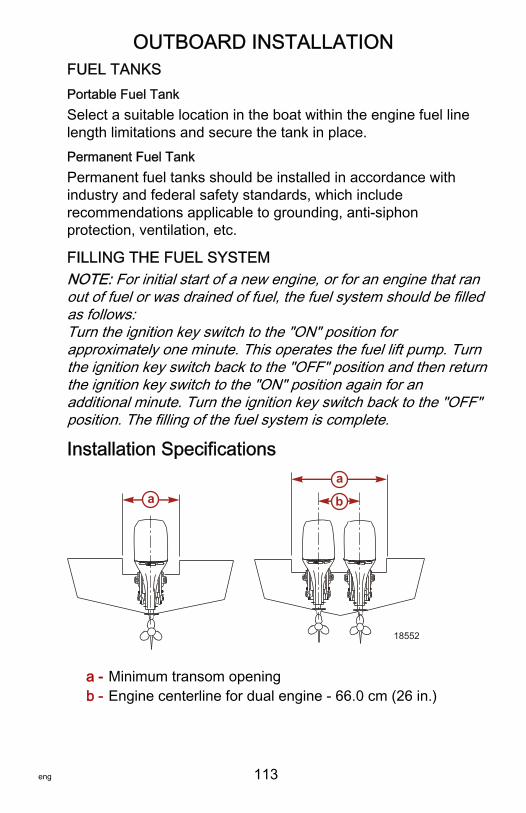
OUTBOARD INSTALLATION
eng 113
FUEL TANKSPortable Fuel TankSelect a suitable location in the boat within the engine fuel linelength limitations and secure the tank in place.Permanent Fuel TankPermanent fuel tanks should be installed in accordance withindustry and federal safety standards, which includerecommendations applicable to grounding, anti‑siphonprotection, ventilation, etc.
FILLING THE FUEL SYSTEMNOTE: For initial start of a new engine, or for an engine that ranout of fuel or was drained of fuel, the fuel system should be filledas follows:Turn the ignition key switch to the "ON" position forapproximately one minute. This operates the fuel lift pump. Turnthe ignition key switch back to the "OFF" position and then returnthe ignition key switch to the "ON" position again for anadditional minute. Turn the ignition key switch back to the "OFF"position. The filling of the fuel system is complete.
Installation Specifications
a - Minimum transom openingb - Engine centerline for dual engine ‑ 66.0 cm (26 in.)
18552
aa
b
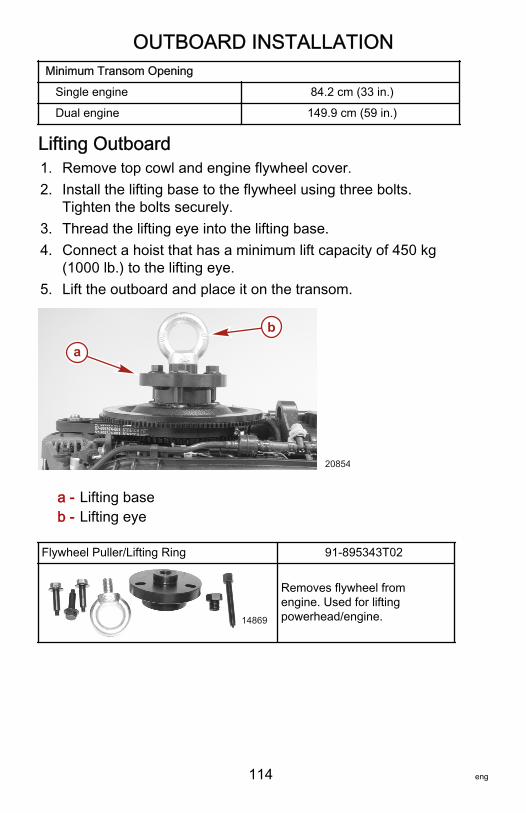
OUTBOARD INSTALLATION
114 eng
Minimum Transom Opening
Single engine 84.2 cm (33 in.)
Dual engine 149.9 cm (59 in.)
Lifting Outboard1. Remove top cowl and engine flywheel cover.2. Install the lifting base to the flywheel using three bolts.
Tighten the bolts securely.3. Thread the lifting eye into the lifting base.4. Connect a hoist that has a minimum lift capacity of 450 kg
(1000 lb.) to the lifting eye.5. Lift the outboard and place it on the transom.
a - Lifting baseb - Lifting eye
Flywheel Puller/Lifting Ring 91‑895343T02
14869
Removes flywheel fromengine. Used for liftingpowerhead/engine.
a
b
20854
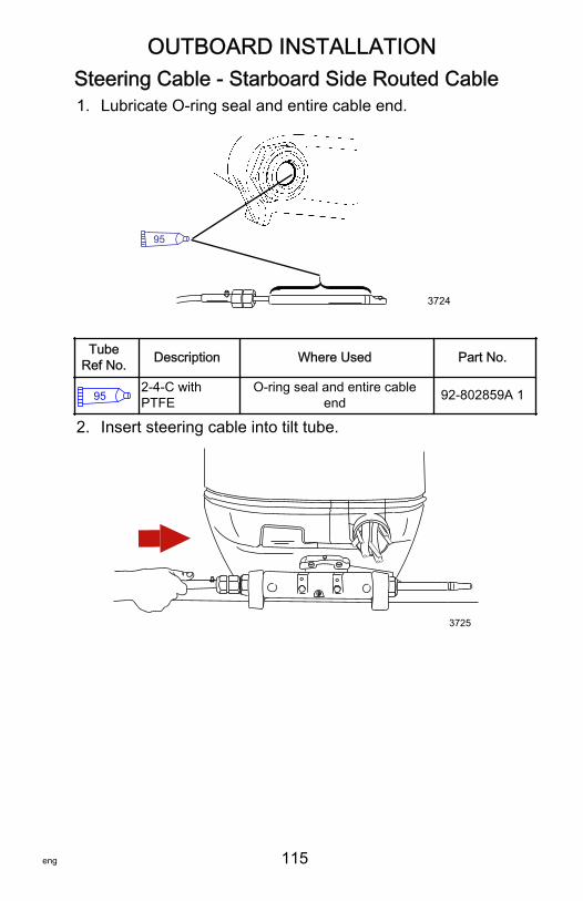
OUTBOARD INSTALLATION
eng 115
Steering Cable ‑ Starboard Side Routed Cable1. Lubricate O‑ring seal and entire cable end.
3724
95
TubeRef No. Description Where Used Part No.
952-4-C withPTFE
O-ring seal and entire cableend 92-802859A 1
2. Insert steering cable into tilt tube.
3725
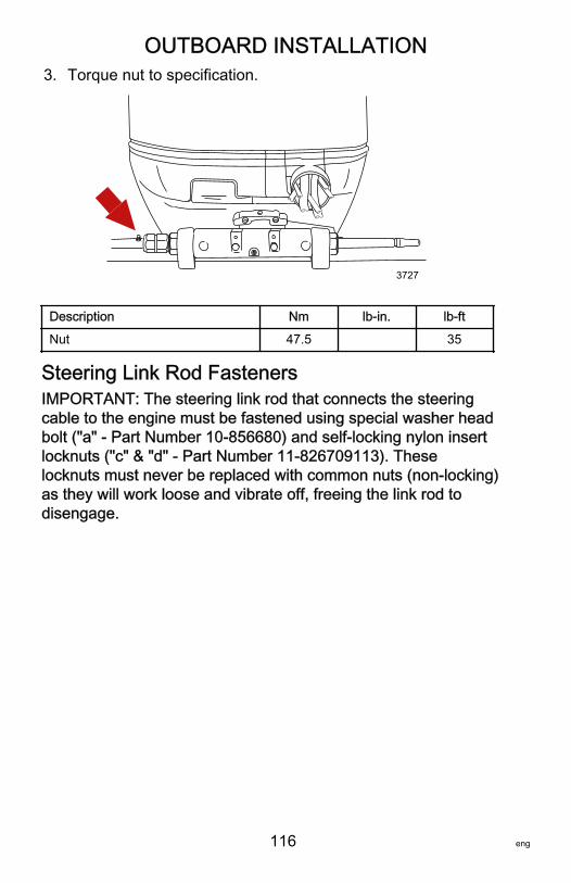
OUTBOARD INSTALLATION
116 eng
3. Torque nut to specification.
3727
Description Nm lb‑in. lb‑ft
Nut 47.5 35
Steering Link Rod FastenersIMPORTANT: The steering link rod that connects the steeringcable to the engine must be fastened using special washer headbolt ("a" ‑ Part Number 10‑856680) and self‑locking nylon insertlocknuts ("c" & "d" ‑ Part Number 11‑826709113). Theselocknuts must never be replaced with common nuts (non‑locking)as they will work loose and vibrate off, freeing the link rod todisengage.
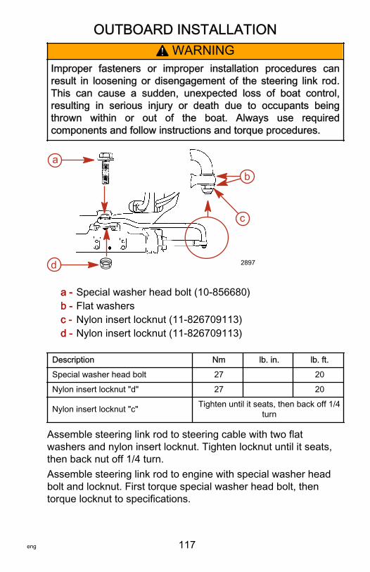
OUTBOARD INSTALLATION
eng 117
! WARNINGImproper fasteners or improper installation procedures canresult in loosening or disengagement of the steering link rod.This can cause a sudden, unexpected loss of boat control,resulting in serious injury or death due to occupants beingthrown within or out of the boat. Always use requiredcomponents and follow instructions and torque procedures.
a - Special washer head bolt (10‑856680)b - Flat washersc - Nylon insert locknut (11‑826709113)d - Nylon insert locknut (11‑826709113)
Description Nm lb. in. lb. ft.
Special washer head bolt 27 20
Nylon insert locknut "d" 27 20
Nylon insert locknut "c" Tighten until it seats, then back off 1/4turn
Assemble steering link rod to steering cable with two flatwashers and nylon insert locknut. Tighten locknut until it seats,then back nut off 1/4 turn.Assemble steering link rod to engine with special washer headbolt and locknut. First torque special washer head bolt, thentorque locknut to specifications.
2897
ab
c
d
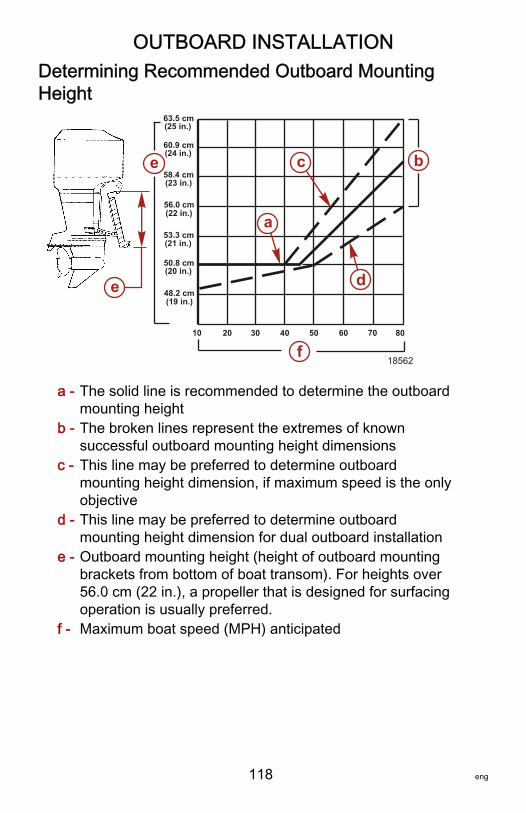
OUTBOARD INSTALLATION
118 eng
Determining Recommended Outboard MountingHeight
a - The solid line is recommended to determine the outboardmounting height
b - The broken lines represent the extremes of knownsuccessful outboard mounting height dimensions
c - This line may be preferred to determine outboardmounting height dimension, if maximum speed is the onlyobjective
d - This line may be preferred to determine outboardmounting height dimension for dual outboard installation
e - Outboard mounting height (height of outboard mountingbrackets from bottom of boat transom). For heights over56.0 cm (22 in.), a propeller that is designed for surfacingoperation is usually preferred.
f - Maximum boat speed (MPH) anticipated
(20 in.)
(21 in.)
(22 in.)
(23 in.)
(24 in.)
(25 in.)
(19 in.)
10 20 30 40 50 60 70 80
63.5 cm
60.9 cm
58.4 cm
56.0 cm
53.3 cm
50.8 cm
48.2 cm
f
bc
d
a
18562
e
e
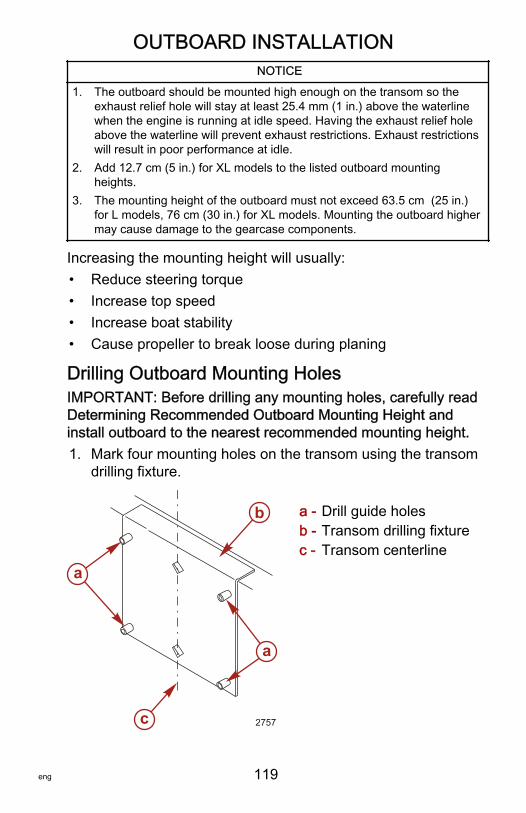
OUTBOARD INSTALLATION
eng 119
NOTICE
1. The outboard should be mounted high enough on the transom so theexhaust relief hole will stay at least 25.4 mm (1 in.) above the waterlinewhen the engine is running at idle speed. Having the exhaust relief holeabove the waterline will prevent exhaust restrictions. Exhaust restrictionswill result in poor performance at idle.
2. Add 12.7 cm (5 in.) for XL models to the listed outboard mountingheights.
3. The mounting height of the outboard must not exceed 63.5 cm (25 in.)for L models, 76 cm (30 in.) for XL models. Mounting the outboard highermay cause damage to the gearcase components.
Increasing the mounting height will usually:• Reduce steering torque• Increase top speed• Increase boat stability• Cause propeller to break loose during planing
Drilling Outboard Mounting HolesIMPORTANT: Before drilling any mounting holes, carefully readDetermining Recommended Outboard Mounting Height andinstall outboard to the nearest recommended mounting height.1. Mark four mounting holes on the transom using the transom
drilling fixture.
a - Drill guide holesb - Transom drilling fixturec - Transom centerline
2757
a
a
b
c

OUTBOARD INSTALLATION
120 eng
Transom Drilling Fixture 91‑98234A2
5489
Aids in engine installation byacting as a template for enginemounting holes.
2. Drill four 13.5 mm (17/32 in.) mounting holes.
3973
Fastening the Outboard to the TransomMOUNTING BOLTS
Outboard Transom Mounting Hardware ‑ Supplied with Outboard
Part Number Part Name Description
10‑67755‑1 Outboard mounting bolt ½‑20 x 4.50 in. long (2.25 in.thread)
11‑826711‑17 Nylon insert locknut ½‑20
12‑28421 Flat washer 1‑1/2 in. diameter
12‑54012 Flat washer 7/8 in. diameter
Available Outboard Mounting Bolts
Part Number Description
10‑67755005 ½‑20 x 2.50 in. long (1.25 in. thread)
10‑67755006 ½‑20 x 3.50 in. long (1.25 in. thread)
10‑814259 ½‑20 x 4.00 in. long (2.25 in. thread)
10‑67755‑1 ½‑20 x 4.50 in. long (2.25 in. thread)
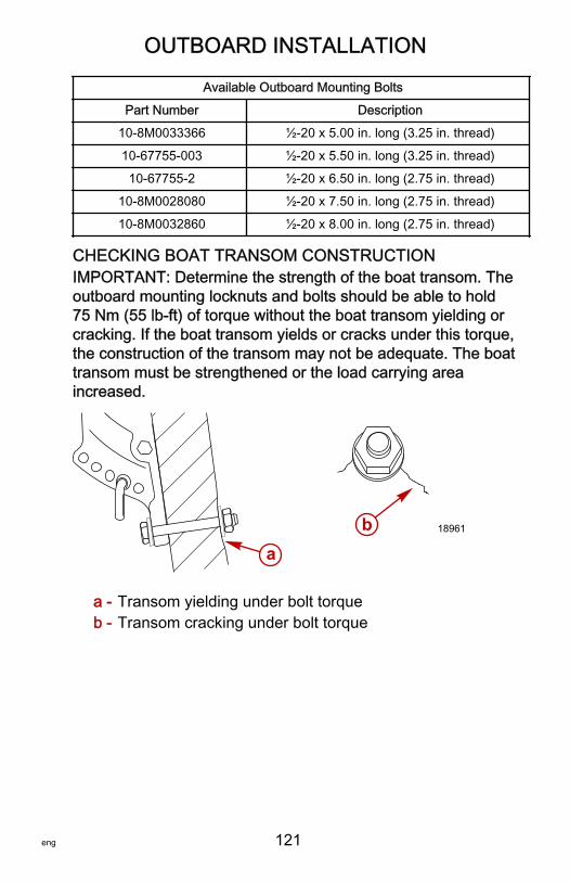
OUTBOARD INSTALLATION
eng 121
Available Outboard Mounting Bolts
Part Number Description
10‑8M0033366 ½‑20 x 5.00 in. long (3.25 in. thread)
10‑67755‑003 ½‑20 x 5.50 in. long (3.25 in. thread)
10‑67755‑2 ½‑20 x 6.50 in. long (2.75 in. thread)
10‑8M0028080 ½‑20 x 7.50 in. long (2.75 in. thread)
10‑8M0032860 ½‑20 x 8.00 in. long (2.75 in. thread)
CHECKING BOAT TRANSOM CONSTRUCTIONIMPORTANT: Determine the strength of the boat transom. Theoutboard mounting locknuts and bolts should be able to hold75 Nm (55 lb‑ft) of torque without the boat transom yielding orcracking. If the boat transom yields or cracks under this torque,the construction of the transom may not be adequate. The boattransom must be strengthened or the load carrying areaincreased.
a - Transom yielding under bolt torqueb - Transom cracking under bolt torque
18961
ab
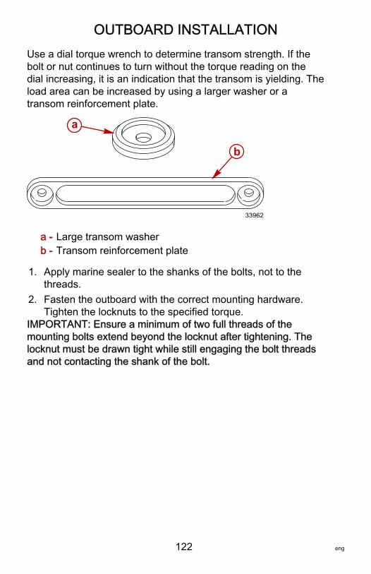
OUTBOARD INSTALLATION
122 eng
Use a dial torque wrench to determine transom strength. If thebolt or nut continues to turn without the torque reading on thedial increasing, it is an indication that the transom is yielding. Theload area can be increased by using a larger washer or atransom reinforcement plate.
a - Large transom washerb - Transom reinforcement plate
1. Apply marine sealer to the shanks of the bolts, not to thethreads.
2. Fasten the outboard with the correct mounting hardware.Tighten the locknuts to the specified torque.
IMPORTANT: Ensure a minimum of two full threads of themounting bolts extend beyond the locknut after tightening. Thelocknut must be drawn tight while still engaging the bolt threadsand not contacting the shank of the bolt.
a
b
33962
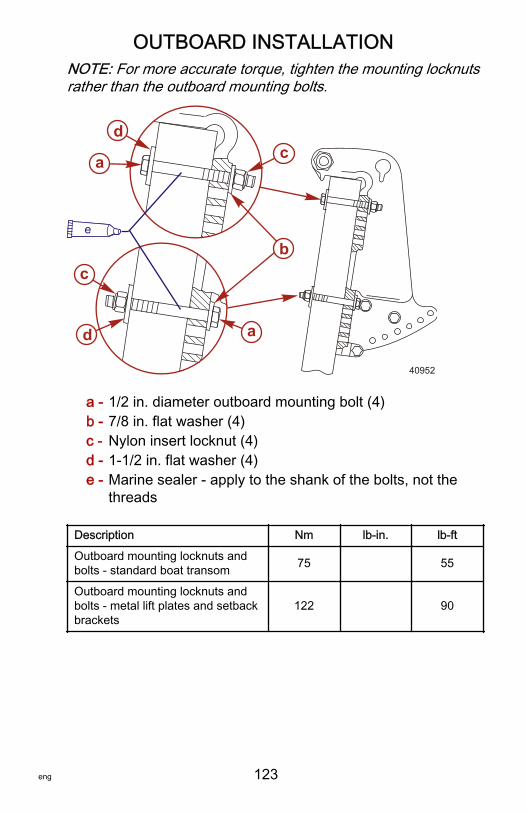
OUTBOARD INSTALLATION
eng 123
NOTE: For more accurate torque, tighten the mounting locknutsrather than the outboard mounting bolts.
a - 1/2 in. diameter outboard mounting bolt (4)b - 7/8 in. flat washer (4)c - Nylon insert locknut (4)d - 1‑1/2 in. flat washer (4)e - Marine sealer ‑ apply to the shank of the bolts, not the
threads
Description Nm lb‑in. lb‑ft
Outboard mounting locknuts andbolts ‑ standard boat transom 75 55
Outboard mounting locknuts andbolts ‑ metal lift plates and setbackbrackets
122 90
a
c
d
ca
d
40952
be
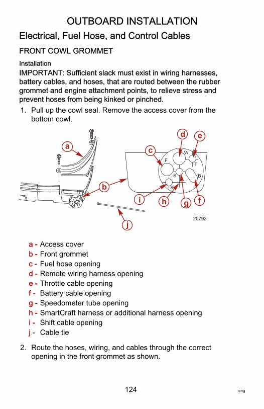
OUTBOARD INSTALLATION
124 eng
Electrical, Fuel Hose, and Control CablesFRONT COWL GROMMETInstallationIMPORTANT: Sufficient slack must exist in wiring harnesses,battery cables, and hoses, that are routed between the rubbergrommet and engine attachment points, to relieve stress andprevent hoses from being kinked or pinched.1. Pull up the cowl seal. Remove the access cover from the
bottom cowl.
a - Access coverb - Front grommetc - Fuel hose openingd - Remote wiring harness openinge - Throttle cable openingf - Battery cable openingg - Speedometer tube openingh - SmartCraft harness or additional harness openingi - Shift cable openingj - Cable tie
2. Route the hoses, wiring, and cables through the correctopening in the front grommet as shown.
a
bf
c
d e
g
20792
hi
j
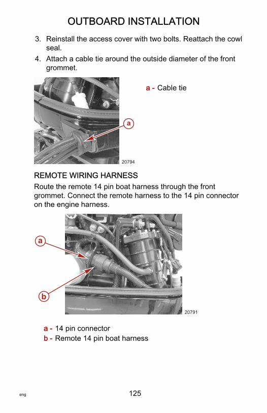
OUTBOARD INSTALLATION
eng 125
3. Reinstall the access cover with two bolts. Reattach the cowlseal.
4. Attach a cable tie around the outside diameter of the frontgrommet.
a - Cable tie
REMOTE WIRING HARNESSRoute the remote 14 pin boat harness through the frontgrommet. Connect the remote harness to the 14 pin connectoron the engine harness.
a - 14 pin connectorb - Remote 14 pin boat harness
a
20794
a
b
20791
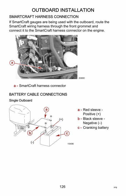
OUTBOARD INSTALLATION
126 eng
SMARTCRAFT HARNESS CONNECTIONIf SmartCraft gauges are being used with the outboard, route theSmartCraft wiring harness through the front grommet andconnect it to the SmartCraft harness connector on the engine.
a - SmartCraft harness connector
BATTERY CABLE CONNECTIONSSingle Outboard
a - Red sleeve ‑Positive (+)
b - Black sleeve ‑Negative (–)
c - Cranking battery
a
20895
(+)
(-)
b
a
c
15496
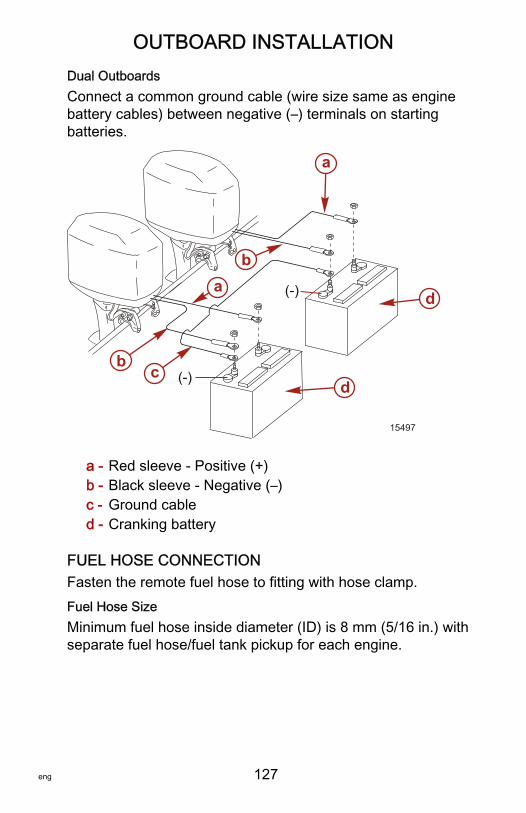
OUTBOARD INSTALLATION
eng 127
Dual OutboardsConnect a common ground cable (wire size same as enginebattery cables) between negative (–) terminals on startingbatteries.
a - Red sleeve ‑ Positive (+)b - Black sleeve ‑ Negative (–)c - Ground cabled - Cranking battery
FUEL HOSE CONNECTIONFasten the remote fuel hose to fitting with hose clamp.Fuel Hose SizeMinimum fuel hose inside diameter (ID) is 8 mm (5/16 in.) withseparate fuel hose/fuel tank pickup for each engine.
(-)
(-)
a
ab
b c
d
d
15497
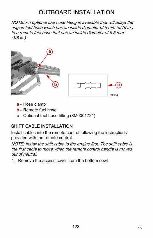
OUTBOARD INSTALLATION
128 eng
NOTE: An optional fuel hose fitting is available that will adapt theengine fuel hose which has an inside diameter of 8 mm (5/16 in.)to a remote fuel hose that has an inside diameter of 9.5 mm(3/8 in.).
a - Hose clampb - Remote fuel hosec - Optional fuel hose fitting (8M0001721)
SHIFT CABLE INSTALLATIONInstall cables into the remote control following the instructionsprovided with the remote control.NOTE: Install the shift cable to the engine first. The shift cable isthe first cable to move when the remote control handle is movedout of neutral.1. Remove the access cover from the bottom cowl.
a
b
22914
c
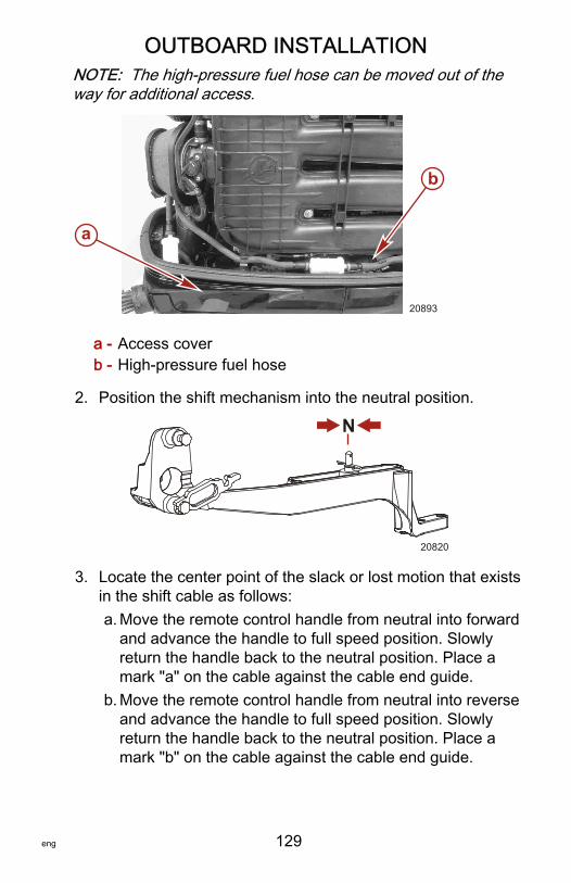
OUTBOARD INSTALLATION
eng 129
NOTE: The high‑pressure fuel hose can be moved out of theway for additional access.
a - Access coverb - High‑pressure fuel hose
2. Position the shift mechanism into the neutral position.
N
20820
3. Locate the center point of the slack or lost motion that existsin the shift cable as follows:a. Move the remote control handle from neutral into forward
and advance the handle to full speed position. Slowlyreturn the handle back to the neutral position. Place amark "a" on the cable against the cable end guide.
b. Move the remote control handle from neutral into reverseand advance the handle to full speed position. Slowlyreturn the handle back to the neutral position. Place amark "b" on the cable against the cable end guide.
a
b
20893
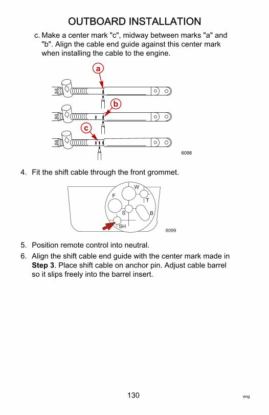
OUTBOARD INSTALLATION
130 eng
c. Make a center mark "c", midway between marks "a" and"b". Align the cable end guide against this center markwhen installing the cable to the engine.
6098
b
c
a
4. Fit the shift cable through the front grommet.
6099
5. Position remote control into neutral.6. Align the shift cable end guide with the center mark made in
Step 3. Place shift cable on anchor pin. Adjust cable barrelso it slips freely into the barrel insert.
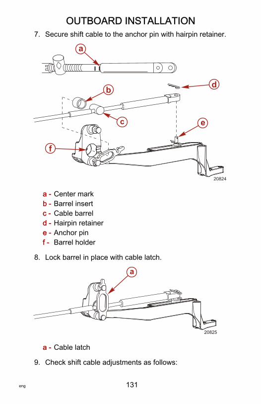
OUTBOARD INSTALLATION
eng 131
7. Secure shift cable to the anchor pin with hairpin retainer.
a - Center markb - Barrel insertc - Cable barreld - Hairpin retainere - Anchor pinf - Barrel holder
8. Lock barrel in place with cable latch.
a - Cable latch
9. Check shift cable adjustments as follows:
a
b d
f
e
20824
c
a
20825
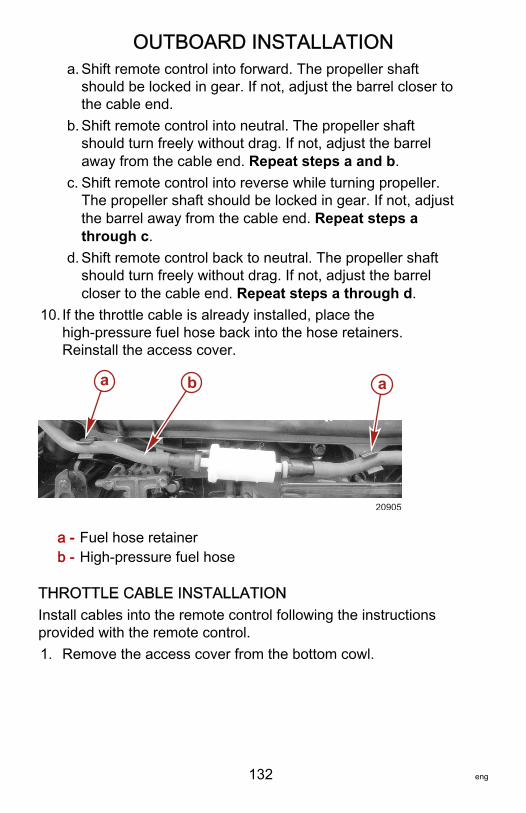
OUTBOARD INSTALLATION
132 eng
a. Shift remote control into forward. The propeller shaftshould be locked in gear. If not, adjust the barrel closer tothe cable end.
b. Shift remote control into neutral. The propeller shaftshould turn freely without drag. If not, adjust the barrelaway from the cable end. Repeat steps a and b.
c. Shift remote control into reverse while turning propeller.The propeller shaft should be locked in gear. If not, adjustthe barrel away from the cable end. Repeat steps athrough c.
d. Shift remote control back to neutral. The propeller shaftshould turn freely without drag. If not, adjust the barrelcloser to the cable end. Repeat steps a through d.
10. If the throttle cable is already installed, place thehigh‑pressure fuel hose back into the hose retainers.Reinstall the access cover.
a - Fuel hose retainerb - High‑pressure fuel hose
THROTTLE CABLE INSTALLATIONInstall cables into the remote control following the instructionsprovided with the remote control.1. Remove the access cover from the bottom cowl.
ba a
20905
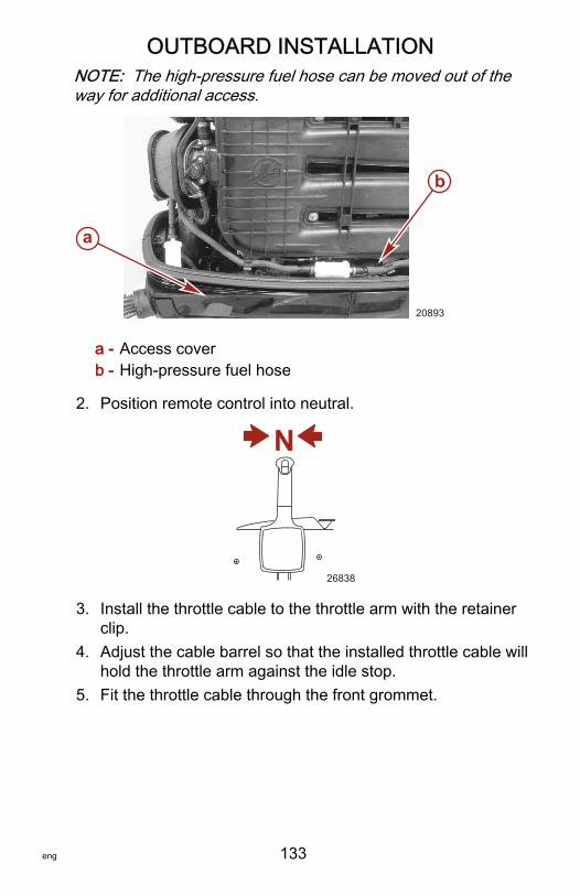
OUTBOARD INSTALLATION
eng 133
NOTE: The high‑pressure fuel hose can be moved out of theway for additional access.
a - Access coverb - High‑pressure fuel hose
2. Position remote control into neutral.
N
26838
3. Install the throttle cable to the throttle arm with the retainerclip.
4. Adjust the cable barrel so that the installed throttle cable willhold the throttle arm against the idle stop.
5. Fit the throttle cable through the front grommet.
a
b
20893
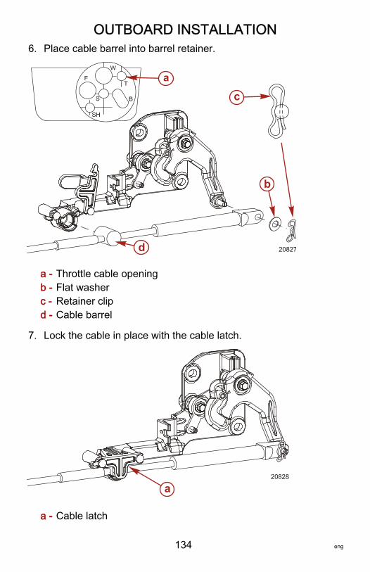
OUTBOARD INSTALLATION
134 eng
6. Place cable barrel into barrel retainer.
a - Throttle cable openingb - Flat washerc - Retainer clipd - Cable barrel
7. Lock the cable in place with the cable latch.
a - Cable latch
a
d
b
c
20827
20828
a
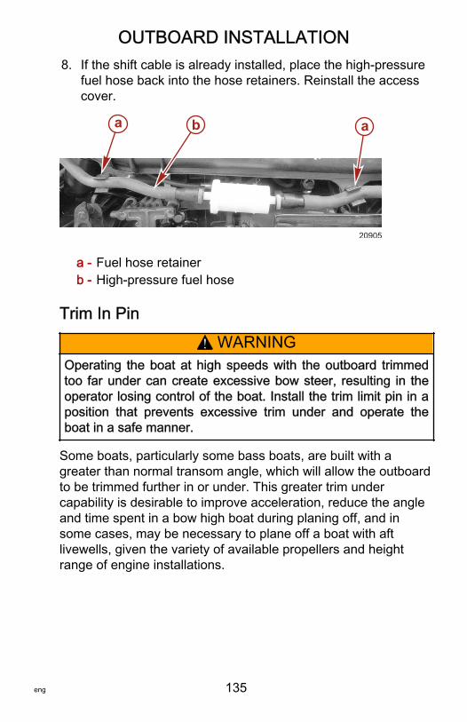
OUTBOARD INSTALLATION
eng 135
8. If the shift cable is already installed, place the high‑pressurefuel hose back into the hose retainers. Reinstall the accesscover.
a - Fuel hose retainerb - High‑pressure fuel hose
Trim In Pin
! WARNINGOperating the boat at high speeds with the outboard trimmedtoo far under can create excessive bow steer, resulting in theoperator losing control of the boat. Install the trim limit pin in aposition that prevents excessive trim under and operate theboat in a safe manner.
Some boats, particularly some bass boats, are built with agreater than normal transom angle, which will allow the outboardto be trimmed further in or under. This greater trim undercapability is desirable to improve acceleration, reduce the angleand time spent in a bow high boat during planing off, and insome cases, may be necessary to plane off a boat with aftlivewells, given the variety of available propellers and heightrange of engine installations.
ba a
20905
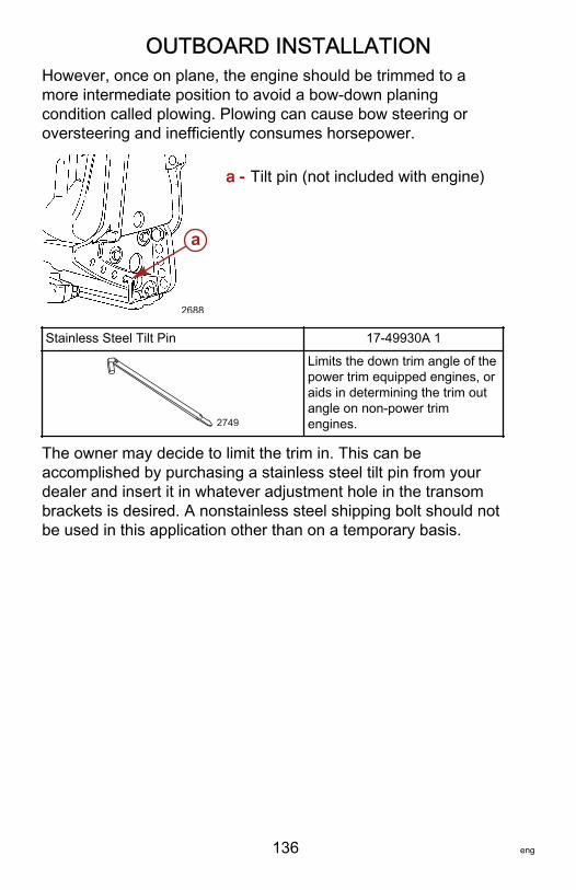
OUTBOARD INSTALLATION
136 eng
However, once on plane, the engine should be trimmed to amore intermediate position to avoid a bow‑down planingcondition called plowing. Plowing can cause bow steering oroversteering and inefficiently consumes horsepower.
a - Tilt pin (not included with engine)
Stainless Steel Tilt Pin 17‑49930A 1
2749
Limits the down trim angle of thepower trim equipped engines, oraids in determining the trim outangle on non‑power trimengines.
The owner may decide to limit the trim in. This can beaccomplished by purchasing a stainless steel tilt pin from yourdealer and insert it in whatever adjustment hole in the transombrackets is desired. A nonstainless steel shipping bolt should notbe used in this application other than on a temporary basis.
2688
a
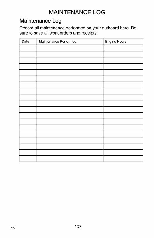
MAINTENANCE LOG
eng 137
Maintenance LogRecord all maintenance performed on your outboard here. Besure to save all work orders and receipts.
Date Maintenance Performed Engine Hours


![HOW TO GUIDE - EFI guides/How to- EFI... · EFI Optitex Fabric List and Parameters. 2 [OP01] Knit_Interlock (100%Cotton) Bend X: 90 dyn*cm Bend Y: 18 dyn*cm Stretch X: 62.18 grf/cm](https://static.fdocuments.us/doc/165x107/5e6b25bedc8a9c7ca01c3ce2/how-to-guide-efi-guideshow-to-efi-efi-optitex-fabric-list-and-parameters.jpg)
