756 IEEE TRANSACTIONS ON CONTROL SYSTEMS …
12
756 IEEE TRANSACTIONS ON CONTROL SYSTEMS TECHNOLOGY, VOL. 17, NO. 4, JULY 2009 Incremental Step Reference Governor for Load Conditioning of Hybrid Fuel Cell and Gas Turbine Power Plants Vasilis Tsourapas, Jing Sun, Fellow, IEEE, and Anna Stefanopoulou Abstract—A hybrid solid oxide fuel cell and gas turbine (SOFC/GT) system exploits the complementary features of the two power plants, where the GT recuperates the energy in the SOFC exhaust stream and thereby boosting the overall system efficiency. Through model based transient analysis, however, it is shown that the intricate coupling dynamics make the transient load following very challenging. Power shutdown has been ob- served when the load is changed abruptly in the generator. In this work, a novel closed-loop reference governor controller is proposed to mitigate the shutdown phenomenon. The reference governor utilizes the region of attraction of a reduced order SOFC/GT model to determine if an incremental step change is allowable, i.e., it does not cause a shutdown. It is shown that with a moderate computational cost, the speed of the hybrid power system response can be improved significantly compared to the fastest conventional load filter. Several design parameters, such as the sampling rate and incremental step-size, are also explored to understand the trade-offs between computational complexity and performance improvement. Index Terms—Dynamics, feedback control, fuel cells (FCs), hy- brid, modeling, solid oxide fuel cell (SOFC). NOMENCLATURE Symbols Concentration of species (mole). Heat capacity (J/kgK). Absolute enthalpy (J/kg). Current density (A m ). Stack current–input (A). Shaft inertia (kgm ). Mass (kg). Manuscript received May 04, 2008; revised August 22, 2008. Manuscript received in final form November 06, 2008. First published April 17, 2009; current version published June 24, 2009. Recommended by Associate Editor N. Kazantzis. This work was supported in part by the ONR under Contract N00014-06-1-0209 and NSF ECS-0501284. V. Tsourapas is with Eaton Corporation, Innovation Center, Southfield, MI 48076 USA (e-mail: [email protected]). J. Sun is with the Department of Naval Architecture and Marine Engi- neering, University of Michigan, Ann Arbor, MI 48109-2145 USA (e-mail: [email protected]). A. Stefanopoulou is with the Department of Mechanical Engineering, Univer- sity of Michigan, Ann Arbor, MI 48109-2121 USA (e-mail: annastef@umich. edu). Color versions of one or more of the figures in this paper are available online at http://ieeexplore.ieee.org. Digital Object Identifier 10.1109/TCST.2008.2010554 Molar Weight (kg/mole). Shaft rotational speed (r/min). Pressure of (Pa). Power (W). Region of attraction. Temperature (K). Voltage (V). Reference governor command. Volume (m ). Flow (kg/s). Molar fraction of species . Abbreviations C Compressor. CB Catalytic burner. ERD Energy recuperation device. FC Fuel cell. FOM Full order model. GEN Generator. GT Gas Turbine. IS-RG Incremental step reference governor. RG Reference governor. ROM Reduced order model. SOFC Solid oxide fuel cell. T Turbine. I. INTRODUCTION F UEL cell (FC)-based power plants offer high efficiency and low emissions compared to conventional power pro- duction technologies such as diesel or gasoline engines. Inte- grating fuel cell based power systems with energy recuperation devices (ERDs) can further improve the system efficiency by reducing the exhaust energy losses. Such integration often re- sults in hybrid power systems, of which the combination of the 1063-6536/$25.00 © 2009 IEEE Authorized licensed use limited to: Jing Sun. Downloaded on November 10, 2009 at 23:06 from IEEE Xplore. Restrictions apply.
Transcript of 756 IEEE TRANSACTIONS ON CONTROL SYSTEMS …

756 IEEE TRANSACTIONS ON CONTROL SYSTEMS TECHNOLOGY, VOL. 17, NO. 4, JULY 2009
Incremental Step Reference Governor for LoadConditioning of Hybrid Fuel Cell and Gas
Turbine Power PlantsVasilis Tsourapas, Jing Sun, Fellow, IEEE, and Anna Stefanopoulou
Abstract—A hybrid solid oxide fuel cell and gas turbine(SOFC/GT) system exploits the complementary features of thetwo power plants, where the GT recuperates the energy in theSOFC exhaust stream and thereby boosting the overall systemefficiency. Through model based transient analysis, however, it isshown that the intricate coupling dynamics make the transientload following very challenging. Power shutdown has been ob-served when the load is changed abruptly in the generator. Inthis work, a novel closed-loop reference governor controller isproposed to mitigate the shutdown phenomenon. The referencegovernor utilizes the region of attraction of a reduced orderSOFC/GT model to determine if an incremental step change isallowable, i.e., it does not cause a shutdown. It is shown that witha moderate computational cost, the speed of the hybrid powersystem response can be improved significantly compared to thefastest conventional load filter. Several design parameters, such asthe sampling rate and incremental step-size, are also explored tounderstand the trade-offs between computational complexity andperformance improvement.
Index Terms—Dynamics, feedback control, fuel cells (FCs), hy-brid, modeling, solid oxide fuel cell (SOFC).
NOMENCLATURE
Symbols
Concentration of species (mole).
Heat capacity (J/kgK).
Absolute enthalpy (J/kg).
Current density (A m ).
Stack current–input (A).
Shaft inertia (kgm ).
Mass (kg).
Manuscript received May 04, 2008; revised August 22, 2008. Manuscriptreceived in final form November 06, 2008. First published April 17, 2009;current version published June 24, 2009. Recommended by Associate EditorN. Kazantzis. This work was supported in part by the ONR under ContractN00014-06-1-0209 and NSF ECS-0501284.
V. Tsourapas is with Eaton Corporation, Innovation Center, Southfield, MI48076 USA (e-mail: [email protected]).
J. Sun is with the Department of Naval Architecture and Marine Engi-neering, University of Michigan, Ann Arbor, MI 48109-2145 USA (e-mail:[email protected]).
A. Stefanopoulou is with the Department of Mechanical Engineering, Univer-sity of Michigan, Ann Arbor, MI 48109-2121 USA (e-mail: [email protected]).
Color versions of one or more of the figures in this paper are available onlineat http://ieeexplore.ieee.org.
Digital Object Identifier 10.1109/TCST.2008.2010554
Molar Weight (kg/mole).
Shaft rotational speed (r/min).
Pressure of (Pa).
Power (W).
Region of attraction.
Temperature (K).
Voltage (V).
Reference governor command.
Volume (m ).
Flow (kg/s).
Molar fraction of species .
Abbreviations
C Compressor.
CB Catalytic burner.
ERD Energy recuperation device.
FC Fuel cell.
FOM Full order model.
GEN Generator.
GT Gas Turbine.
IS-RG Incremental step reference governor.
RG Reference governor.
ROM Reduced order model.
SOFC Solid oxide fuel cell.
T Turbine.
I. INTRODUCTION
F UEL cell (FC)-based power plants offer high efficiencyand low emissions compared to conventional power pro-
duction technologies such as diesel or gasoline engines. Inte-grating fuel cell based power systems with energy recuperationdevices (ERDs) can further improve the system efficiency byreducing the exhaust energy losses. Such integration often re-sults in hybrid power systems, of which the combination of the
1063-6536/$25.00 © 2009 IEEE
Authorized licensed use limited to: Jing Sun. Downloaded on November 10, 2009 at 23:06 from IEEE Xplore. Restrictions apply.
TSOURAPAS et al.: INCREMENTAL STEP REFERENCE GOVERNOR FOR LOAD CONDITIONING OF HYBRID FUEL CELL AND GAS TURBINE POWER PLANTS 757
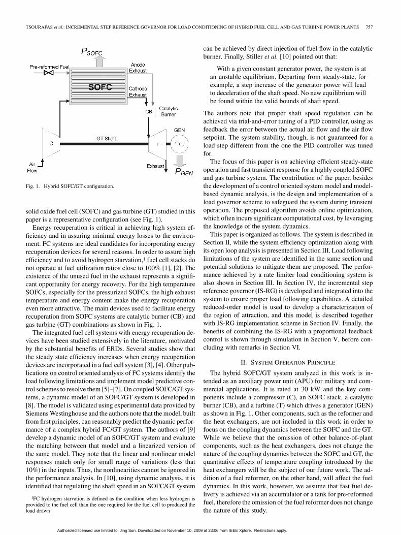
Fig. 1. Hybrid SOFC/GT configuration.
solid oxide fuel cell (SOFC) and gas turbine (GT) studied in thispaper is a representative configuration (see Fig. 1).
Energy recuperation is critical in achieving high system ef-ficiency and in assuring minimal energy losses to the environ-ment. FC systems are ideal candidates for incorporating energyrecuperation devices for several reasons. In order to assure highefficiency and to avoid hydrogen starvation,1 fuel cell stacks donot operate at fuel utilization ratios close to 100% [1], [2]. Theexistence of the unused fuel in the exhaust represents a signifi-cant opportunity for energy recovery. For the high temperatureSOFCs, especially for the pressurized SOFCs, the high exhausttemperature and energy content make the energy recuperationeven more attractive. The main devices used to facilitate energyrecuperation from SOFC systems are catalytic burner (CB) andgas turbine (GT) combinations as shown in Fig. 1.
The integrated fuel cell systems with energy recuperation de-vices have been studied extensively in the literature, motivatedby the substantial benefits of ERDs. Several studies show thatthe steady state efficiency increases when energy recuperationdevices are incorporated in a fuel cell system [3], [4]. Other pub-lications on control oriented analysis of FC systems identify theload following limitations and implement model predictive con-trol schemes to resolve them [5]–[7]. On coupled SOFC/GT sys-tems, a dynamic model of an SOFC/GT system is developed in[8]. The model is validated using experimental data provided bySiemens Westinghouse and the authors note that the model, builtfrom first principles, can reasonably predict the dynamic perfor-mance of a complex hybrid FC/GT system. The authors of [9]develop a dynamic model of an SOFC/GT system and evaluatethe matching between that model and a linearized version ofthe same model. They note that the linear and nonlinear modelresponses match only for small range of variations (less that10%) in the inputs. Thus, the nonlinearities cannot be ignored inthe performance analysis. In [10], using dynamic analysis, it isidentified that regulating the shaft speed in an SOFC/GT system
1FC hydrogen starvation is defined as the condition when less hydrogen isprovided to the fuel cell than the one required for the fuel cell to produced theload drawn
can be achieved by direct injection of fuel flow in the catalyticburner. Finally, Stiller et al. [10] pointed out that:
With a given constant generator power, the system is atan unstable equilibrium. Departing from steady-state, forexample, a step increase of the generator power will leadto deceleration of the shaft speed. No new equilibrium willbe found within the valid bounds of shaft speed.
The authors note that proper shaft speed regulation can beachieved via trial-and-error tuning of a PID controller, using asfeedback the error between the actual air flow and the air flowsetpoint. The system stability, though, is not guaranteed for aload step different from the one the PID controller was tunedfor.
The focus of this paper is on achieving efficient steady-stateoperation and fast transient response for a highly coupled SOFCand gas turbine system. The contribution of the paper, besidesthe development of a control oriented system model and model-based dynamic analysis, is the design and implementation of aload governor scheme to safeguard the system during transientoperation. The proposed algorithm avoids online optimization,which often incurs significant computational cost, by leveragingthe knowledge of the system dynamics.
This paper is organized as follows. The system is described inSection II, while the system efficiency optimization along withits open loop analysis is presented in Section III. Load followinglimitations of the system are identified in the same section andpotential solutions to mitigate them are proposed. The perfor-mance achieved by a rate limiter load conditioning system isalso shown in Section III. In Section IV, the incremental stepreference governor (IS-RG) is developed and integrated into thesystem to ensure proper load following capabilities. A detailedreduced-order model is used to develop a characterization ofthe region of attraction, and this model is described togetherwith IS-RG implementation scheme in Section IV. Finally, thebenefits of combining the IS-RG with a proportional feedbackcontrol is shown through simulation in Section V, before con-cluding with remarks in Section VI.
II. SYSTEM OPERATION PRINCIPLE
The hybrid SOFC/GT system analyzed in this work is in-tended as an auxiliary power unit (APU) for military and com-mercial applications. It is rated at 30 kW and the key com-ponents include a compressor (C), an SOFC stack, a catalyticburner (CB), and a turbine (T) which drives a generator (GEN)as shown in Fig. 1. Other components, such as the reformer andthe heat exchangers, are not included in this work in order tofocus on the coupling dynamics between the SOFC and the GT.While we believe that the omission of other balance-of-plantcomponents, such as the heat exchangers, does not change thenature of the coupling dynamics between the SOFC and GT, thequantitative effects of temperature coupling introduced by theheat exchangers will be the subject of our future work. The ad-dition of a fuel reformer, on the other hand, will affect the fueldynamics. In this work, however, we assume that fast fuel de-livery is achieved via an accumulator or a tank for pre-reformedfuel, therefore the omission of the fuel reformer does not changethe nature of this study.
Authorized licensed use limited to: Jing Sun. Downloaded on November 10, 2009 at 23:06 from IEEE Xplore. Restrictions apply.
758 IEEE TRANSACTIONS ON CONTROL SYSTEMS TECHNOLOGY, VOL. 17, NO. 4, JULY 2009
The air to the SOFC is supplied to the cathode side by acompressor, while fuel is fed to the anode side. The exhaustfrom the SOFC outlet passes through the CB where the unusedfuel is burned to increase the temperature and pressure of theflow. The high temperature and high pressure flow from the CBthen powers the turbine, thereby providing a mechanism to re-cuperate the exhaust energy. The turbine drives both the com-pressor and the generator through a mechanical shaft; the formerdelivers the air needed for the SOFC stack operation and thelatter provides additional electrical power for the system. Thenet power output is the sum of the electric power from the SOFCand the generator. In order to explore the dynamic characteris-tics of the integrated SOFC/GT system, our effort is initiallydevoted to developing a dynamic model that captures both thesteady state and dynamic behavior of the system. The modelingdetails for components can be found in [1], [11] for the SOFCand in [2], [12]–[14] for the CB, GT, and the integrated system.
The integrated model has 55 states, of which 52 are the nec-essary states for capturing the SOFC dynamics from [1], 2 arefrom the CB and 1 is from the GT shaft dynamics. The mainSOFC states include the temperature, flow and chemical ki-netics. The input variables to the system are the fuel flow, ,the current drawn from the SOFC stack and the generatorload . The optimal setpoints for these inputs to achieve thebest system efficiency are determined by an optimization, aselaborated in the next section, while a simplified model used toexplain the control methodology proposed in this work is alsodeveloped in subsequent sections.
III. OPEN-LOOP ANALYSIS
In this section, we first perform the model-based optimizationto determine the setpoints for the fuel flow, the generator loadand the SOFC current. It is shown that the system is susceptibleto power shutdown when an abrupt load increase is applied. Themodel-based analysis shows that shutdown occurs even when asmall load step is applied, thereby rendering the feedforwardcontrol based on the optimized setpoints not feasible for thishighly integrated system. Further analysis reveals that this phe-nomenon is largely attributed to the shaft rotational dynamicsand the rapid increase in the generator load.
A. Steady-State Optimization
The hybrid SOFC/GT system involves multiple actuators andinputs whose setting will dictate the system operation safety andefficiency. In this study, three inputs: the fuel flow supply, thecurrent drawn from the SOFC and the load applied to the gen-erator, are considered. For a given fuel flow, different combina-tions of current drawn from the SOFC and load applied to thegenerator will yield different net power. Note that the net power,
, of the system is defined as the sum of the power output ofthe fuel cell and the power output of the generator
(1)
In order to determine the maximum steady-state net poweroutput for a given fuel flow, the following optimization problemis solved using the developed model and gradient optimization:
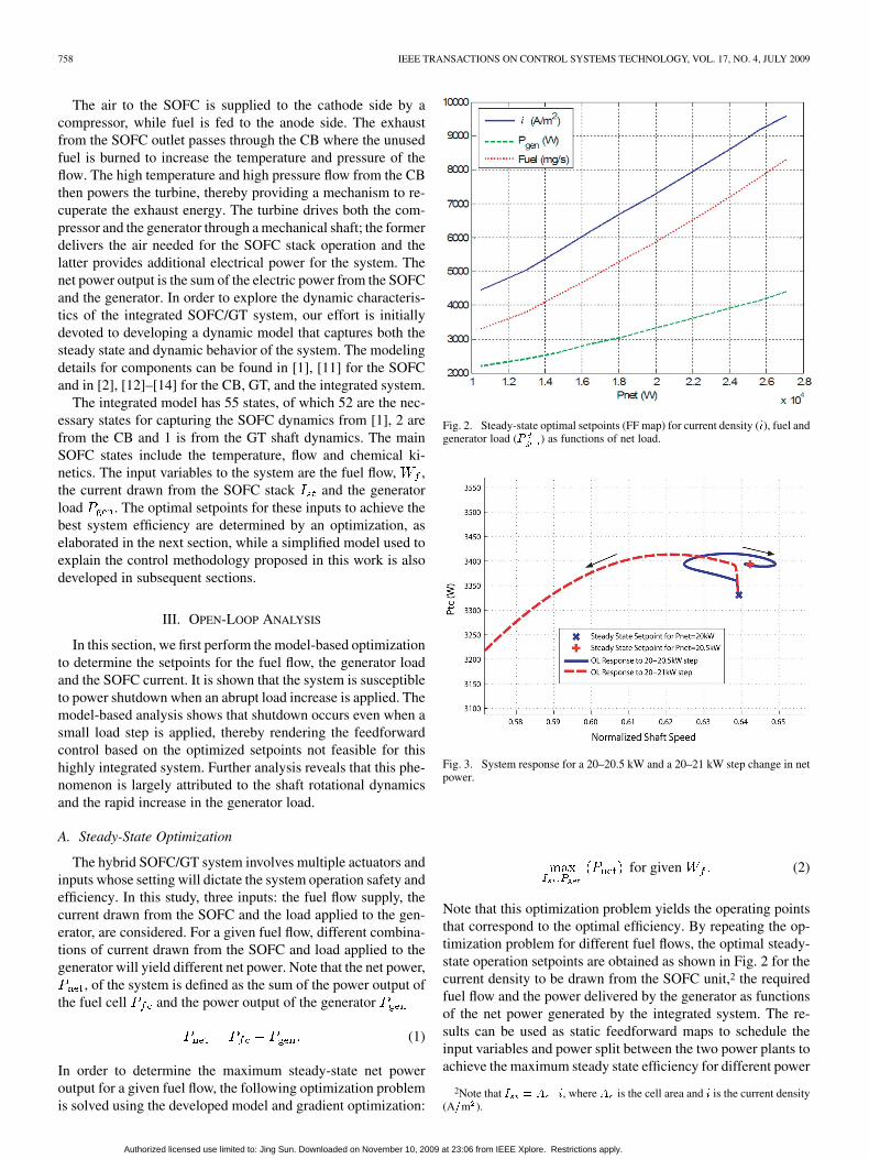
Fig. 2. Steady-state optimal setpoints (FF map) for current density (�), fuel andgenerator load (� ) as functions of net load.
Fig. 3. System response for a 20–20.5 kW and a 20–21 kW step change in netpower.
for given (2)
Note that this optimization problem yields the operating pointsthat correspond to the optimal efficiency. By repeating the op-timization problem for different fuel flows, the optimal steady-state operation setpoints are obtained as shown in Fig. 2 for thecurrent density to be drawn from the SOFC unit,2 the requiredfuel flow and the power delivered by the generator as functionsof the net power generated by the integrated system. The re-sults can be used as static feedforward maps to schedule theinput variables and power split between the two power plants toachieve the maximum steady state efficiency for different power
2Note that � � � � �, where � is the cell area and � is the current density(A�m ).
Authorized licensed use limited to: Jing Sun. Downloaded on November 10, 2009 at 23:06 from IEEE Xplore. Restrictions apply.
TSOURAPAS et al.: INCREMENTAL STEP REFERENCE GOVERNOR FOR LOAD CONDITIONING OF HYBRID FUEL CELL AND GAS TURBINE POWER PLANTS 759
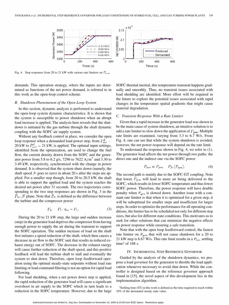
Fig. 4. Step responses from 20 to 21 kW with various rate limiters on � .
demands. This operation strategy, where the inputs are deter-mined as functions of the net power demand, is referred to inthis work as the open-loop control scheme.
B. Shutdown Phenomenon of the Open-Loop System
In this section, dynamic analysis is performed to understandthe open-loop system dynamic characteristics. It is shown thatthe system is susceptible to power shutdown when an abruptload increase is applied. The analysis here reveals that the shut-down is initiated by the gas turbine through the shaft dynamiccoupling with the SOFC air supply system.
Without any feedback control in place, we consider the openloop response when a demanded load power step, from20 kW to 21 kW, is applied. The optimal input settings,identified from the optimization, are used to change the fuelflow, the current density drawn from the SOFC and the gener-ator power from 5.8 to 6.2 g/s, 7296 to 7622 A m and 3.30 to3.49 kW, respectively, synchronized with the change in powerdemand. It is observed that the system shuts down (namely, theshaft speed goes to zero) in about 20 s after the steps are ap-plied. For a smaller step though, from 20 to 20.5 kW, the shaftis able to support the applied load and the system reaches thedesired net power after 31 seconds. The two trajectories corre-sponding to the two step responses are shown in Fig. 3 in the
, plane. Note that is defined as the difference betweenthe turbine and the compressor power
(3)
During the 20 to 21 kW step, the large and sudden increase(step) in the generator load deprives the compressor from havingenough power to supply the air during the transient to supportthe SOFC operation. The sudden increase of load on the shaftfirst initiates a speed reduction of the shaft, which then causes adecrease in air flow to the SOFC unit that results in reduced ex-haust energy out of SOFC. The decrease in the exhaust energywill cause further reduction of the shaft speed, and this positivefeedback will lead the turbine shaft to stall and eventually thesystem to shut down. Therefore, open loop feedforward oper-ation using the optimal steady-state setpoints without load ratelimiting or load command filtering is not an option for rapid loadfollowing.
For load shedding, when a net power down step is applied,the rapid reduction of the generator load will cause a significantovershoot in air supply to the SOFC which in turn leads to areduction in the SOFC temperature. However, due to the large
SOFC thermal inertial, this temperature transient happens grad-ually and smoothly. Thus, no transient issues associated withload shedding are identified. More effort will be required inthe future to explore the potential issues associated with rapidchanges in the temperature spatial gradients that might causematerial degradation.
C. Transient Response With a Rate Limiter
Given that a rapid increase in the generator load was shown tobe the main cause of system shutdown, an intuitive solution is toadd a rate limiter to slow down the application of . Multiplerate limits are examined, varying from 3.3 to 6.7 W/s. FromFig. 4, one can see that while the system shutdown is avoided,however, the net power response will depend on the rate limit.
To understand the response shown in Fig. 4, we refer to (1).The generator load affects the net power through two paths: thedirect one and the indirect one via the SOFC power
(4)
The second path is mainly due to the SOFC-GT coupling. Notethat lower will lead to more air being delivered to theSOFC, which results in lower SOFC temperature and thus lowerSOFC power. Therefore, the power response will have doublepenalty when is slowed down. Another issue with a con-stant rate limiter is that when it is optimized for a given step, itwill be suboptimal for smaller steps and insufficient for largersteps. In order to optimize the performance for all operating con-ditions, the limiter has to be scheduled not only for different stepsizes, but also for different state conditions. This motivates us toseek for other solutions that can minimize the negative effectson power response while ensuring a safe transition.
Note that with the open loop feedforward control, the fastestrate limiter on that will not cause shutdown for a 20 to21 kW step is 6.67 W/s. This rate limit results in a settlingtime3 of 168 s.
IV. INCREMENTAL STEP REFERENCE GOVERNOR
Guided by the analysis of the shutdown dynamics, we pro-pose a load governor for the generator to throttle the load appli-cation whenever necessary to avoid shut down. While the con-troller is designed based on the reference governor approachfound in [15], the novel aspect of this development lies in theimplementation algorithm.
3Settling time (ST) in this work is defined as the time required to reach within10% of the demanded steady state value.
Authorized licensed use limited to: Jing Sun. Downloaded on November 10, 2009 at 23:06 from IEEE Xplore. Restrictions apply.
760 IEEE TRANSACTIONS ON CONTROL SYSTEMS TECHNOLOGY, VOL. 17, NO. 4, JULY 2009
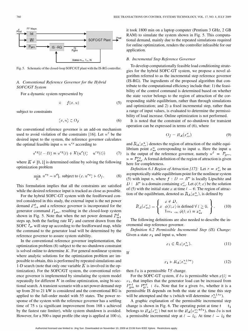
Fig. 5. Schematic of the closed-loop SOFC/GT plant with the IS-RG controller.
A. Conventional Reference Governor for the HybridSOFC/GT System
For a dynamic system represented by
(5)
subject to constraints
(6)
the conventional reference governor is an add-on mechanismused to avoid violation of the constraints [16]. Let be thedesired input to the system, the reference governor calculatesthe optimal feasible input according to
(7)
where is determined online by solving the followingoptimization problem
subject to (8)
This formulation implies that all the constraints are satisfiedwhile the desired reference input is tracked as close as possible.
For the hybrid SOFC-GT system with the feedforward con-trol considered in this study, the external input is the net powerdemand and a reference governor is incorporated for thegenerator command , resulting in the closed-loop systemshown in Fig. 5. Note that when the net power demandsteps up, both the fueling rate and current drawn from theSOFC will step up according to the feedforward map, whilethe command to the generator load will be determined by thereference governor to assure system stability.
In the conventional reference governor implementation, theoptimization problem (8) subject to the no-shutdown constraintis solved online to determine . For general nonlinear systemswhere analytic solutions for the optimization problem are im-possible to obtain, this is performed by repeated simulations and1-D search (note that only one variable is involved in the op-timization). For the SOFC/GT system, the conventional refer-ence governor is implemented by simulating the system modelrepeatedly for different in online optimization, using bi-sec-tional search. A transient scenario with a net power demand stepup from 20 to 21 kW is considered and the conventional RG isapplied to the full-order model with 55 states. The power re-sponse of the system with the reference governor has a settlingtime of 75 s (a significant improvement from 168 s achievedby the fastest rate limiter), while system shutdown is avoided.However, for a 500-s input profile (the step is applied at 100 s),
it took 1800 min on a laptop computer (Pentium 3 GHz, 2 GBRAM) to simulate the system shown in Fig. 5. This computa-tional demand, mainly due to the repeated simulations requiredfor online optimization, renders the controller infeasible for ourapplication.
B. Incremental Step Reference Governor
To develop computationally feasible load conditioning strate-gies for the hybrid SOFC-GT system, we propose a novel al-gorithm referred to as the incremental step reference governor(IS-RG). The ingredients of the proposed algorithm that con-tribute to the computational efficiency include that: 1) the feasi-bility of the control command is determined based on whetherthe state vector belongs to the region of attraction of the cor-responding stable equilibrium, rather than through simulationsand optimization; and 2) a fixed incremental step, rather thana range of input values, is evaluated to determine the permissi-bility of load increase. Online optimization is not performed.
It is noted that the constraint of no-shutdown for transientoperation can be expressed in terms of (6), where
(9)
and denotes the region of attraction of the stable equi-librium point corresponding to input . Here the inputis the output of the reference governor, namely ,
. A formal definition of the region of attraction is givenhere for completeness.
Definition 6.1 Region of Attraction [17]: Let be anasymptotically stable equilibrium point for the nonlinear system(5) with input , where is locally Lipschitz and
is a domain containing . Let be the solutionof (5) with the initial state at time . The region of attrac-tion of the equilibrium, denoted as , is defined by
is defined (10)
The following definitions are also needed to describe the in-cremental step reference governor.
Definition 6.2 Permissible Incremental Step (IS) Change:Given a state and input , where
(11)
If
(12)
then is a permissible change.For the SOFC-GT system, if is permissible when, that implies that the generator load can be increased from
to . Note that for a given , whether it is apermissible IS depends on both the state at the time this stepwill be attempted and the (which will determine ).
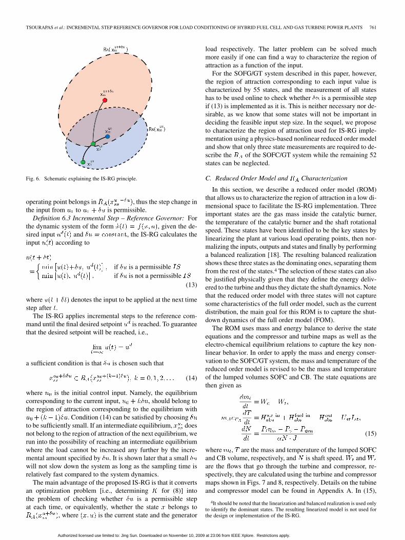
A graphic explanation of the permissible incremental stepchange is shown in Fig. 6. The operating point at timebelongs to but not to the , thus is nota permissible incremental step at . At time the
Authorized licensed use limited to: Jing Sun. Downloaded on November 10, 2009 at 23:06 from IEEE Xplore. Restrictions apply.
TSOURAPAS et al.: INCREMENTAL STEP REFERENCE GOVERNOR FOR LOAD CONDITIONING OF HYBRID FUEL CELL AND GAS TURBINE POWER PLANTS 761
Fig. 6. Schematic explaining the IS-RG principle.
operating point belongs in , thus the step change inthe input from to is permissible.
Definition 6.3 Incremental Step – Reference Governor: Forthe dynamic system of the form , given the de-sired input and , the IS-RG calculates theinput according to
if is a permissibleif is not a permissible
(13)
where denotes the input to be applied at the next timestep after .
The IS-RG applies incremental steps to the reference com-mand until the final desired setpoint is reached. To guaranteethat the desired setpoint will be reached, i.e.,
a sufficient condition is that is chosen such that
(14)
where is the initial control input. Namely, the equilibriumcorresponding to the current input, , should belong tothe region of attraction corresponding to the equilibrium with
. Condition (14) can be satisfied by choosingto be sufficiently small. If an intermediate equilibrium, doesnot belong to the region of attraction of the next equilibrium, werun into the possibility of reaching an intermediate equilibriumwhere the load cannot be increased any further by the incre-mental amount specified by . It is shown later that a smallwill not slow down the system as long as the sampling time isrelatively fast compared to the system dynamics.
The main advantage of the proposed IS-RG is that it convertsan optimization problem [i.e., determining for (8)] intothe problem of checking whether is a permissible stepat each time, or equivalently, whether the state belongs to
, where is the current state and the generator
load respectively. The latter problem can be solved muchmore easily if one can find a way to characterize the region ofattraction as a function of the input.
For the SOFG/GT system described in this paper, however,the region of attraction corresponding to each input value ischaracterized by 55 states, and the measurement of all stateshas to be used online to check whether is a permissible stepif (13) is implemented as it is. This is neither necessary nor de-sirable, as we know that some states will not be important indeciding the feasible input step size. In the sequel, we proposeto characterize the region of attraction used for IS-RG imple-mentation using a physics-based nonlinear reduced order modeland show that only three state measurements are required to de-scribe the of the SOFC/GT system while the remaining 52states can be neglected.
C. Reduced Order Model and Characterization
In this section, we describe a reduced order model (ROM)that allows us to characterize the region of attraction in a low di-mensional space to facilitate the IS-RG implementation. Threeimportant states are the gas mass inside the catalytic burner,the temperature of the catalytic burner and the shaft rotationalspeed. These states have been identified to be the key states bylinearizing the plant at various load operating points, then nor-malizing the inputs, outputs and states and finally by performinga balanced realization [18]. The resulting balanced realizationshows these three states as the dominating ones, separating themfrom the rest of the states.4 The selection of these states can alsobe justified physically given that they define the energy deliv-ered to the turbine and thus they dictate the shaft dynamics. Notethat the reduced order model with three states will not capturesome characteristics of the full order model, such as the currentdistribution, the main goal for this ROM is to capture the shut-down dynamics of the full order model (FOM).
The ROM uses mass and energy balance to derive the stateequations and the compressor and turbine maps as well as theelectro-chemical equilibrium relations to capture the key non-linear behavior. In order to apply the mass and energy conser-vation to the SOFC/GT system, the mass and temperature of thereduced order model is revised to be the mass and temperatureof the lumped volumes SOFC and CB. The state equations arethen given as
(15)
where , are the mass and temperature of the lumped SOFCand CB volume, respectively, and is shaft speed. andare the flows that go through the turbine and compressor, re-spectively, they are calculated using the turbine and compressormaps shown in Figs. 7 and 8, respectively. Details on the tubineand compressor model can be found in Appendix A. In (15),
4It should be noted that the linearization and balanced realization is used onlyto identify the dominant states. The resulting linearized model is not used forthe design or implementation of the IS-RG.
Authorized licensed use limited to: Jing Sun. Downloaded on November 10, 2009 at 23:06 from IEEE Xplore. Restrictions apply.

762 IEEE TRANSACTIONS ON CONTROL SYSTEMS TECHNOLOGY, VOL. 17, NO. 4, JULY 2009
Fig. 7. Compressor map used for both FOM and ROM.
2.84 kg is the total mass of the SOFC and CB,500 J/kg/K is the average heat capacity of all the SOFC solidlayers (including the inter-connector and PEN) and is theabsolute enthalpy defined as the enthalpy at inlet or outlet tem-perature, minus the enthalpy at reference temperature (273 K) plus the enthalpy of formation:
(16)
Note that, is the absolute enthalpy of the incoming airfrom the compressor, is the absolute enthalpy of the in-coming fuel and is the sum of the absolute enthalpy of theoutlet flow species. Seven species are assumed in the CB outletflow, namely , , , , , , . Furthermore,
and are the mole fraction and formation enthalpy of theth species. Note that is calculated from the FOM as a func-
tion of the load and implemented in the ROM as look-uptables. An example of such a lookup table for the species isgiven in Fig. 9. Similar maps are integrated for all eight species.This simplification was done based on the results of [11], whereit is shown that the reaction kinetics are very fast compared tothe temperature dynamics and thus can be ignored.
Furthermore, the pressure in the lumped unit is calculatedfrom the ideal gas law as , with being the pressure,
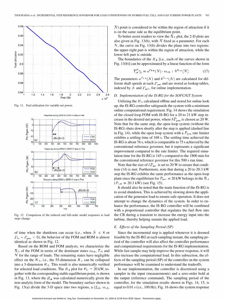
is the sum of moles in the volume and is the volume of theSOFC and CB. Finally, and are the SOFC stack voltageand current respectively and are calculated from the FOM. Thestack voltage-current relationship is shown in Fig. 10. Note thatFig. 10 is not the polarization curve of the SOFC stack, forwhich the partial pressure of reactants and temperature are oftenheld as constant. Instead, Fig. 10 reflects the fact that fuel uti-lization is changed for different load (current) over the load (cur-rent) range according to the optimization results. The fuel uti-lization as a function of net power is shown in Fig. 11, wherefuel utilization is defined as the amount of fuel provided to theSOFC over the amount of fuel that is exiting the SOFC.
Fig. 8. Turbine map used for both FOM and ROM.
Fig. 9. CO molar fraction in ROM as a function of load.
Fig. 10. Stack voltage-current relationship for the SOFC with the feedforwardcontrol.
Comparing the response of the FOM and the ROM in terms ofthe shaft power, the two models match well as shown in Fig. 12.Most importantly, the shutdown effect is captured during a 660W step as shown in Fig. 12(c). Note that during the period
Authorized licensed use limited to: Jing Sun. Downloaded on November 10, 2009 at 23:06 from IEEE Xplore. Restrictions apply.
TSOURAPAS et al.: INCREMENTAL STEP REFERENCE GOVERNOR FOR LOAD CONDITIONING OF HYBRID FUEL CELL AND GAS TURBINE POWER PLANTS 763
Fig. 11. Fuel utilization for variable net power.
Fig. 12. Comparison of the reduced and full-order model responses to loadsteps change.
of time when the shutdown can occur (i.e., when or), the behavior of the FOM and ROM is almost
identical as shown in Fig. 12.Based on the ROM and FOM analysis, we characterize the
of the FOM in terms of the dominant states , andfor the range of loads. The remaining states have negligible
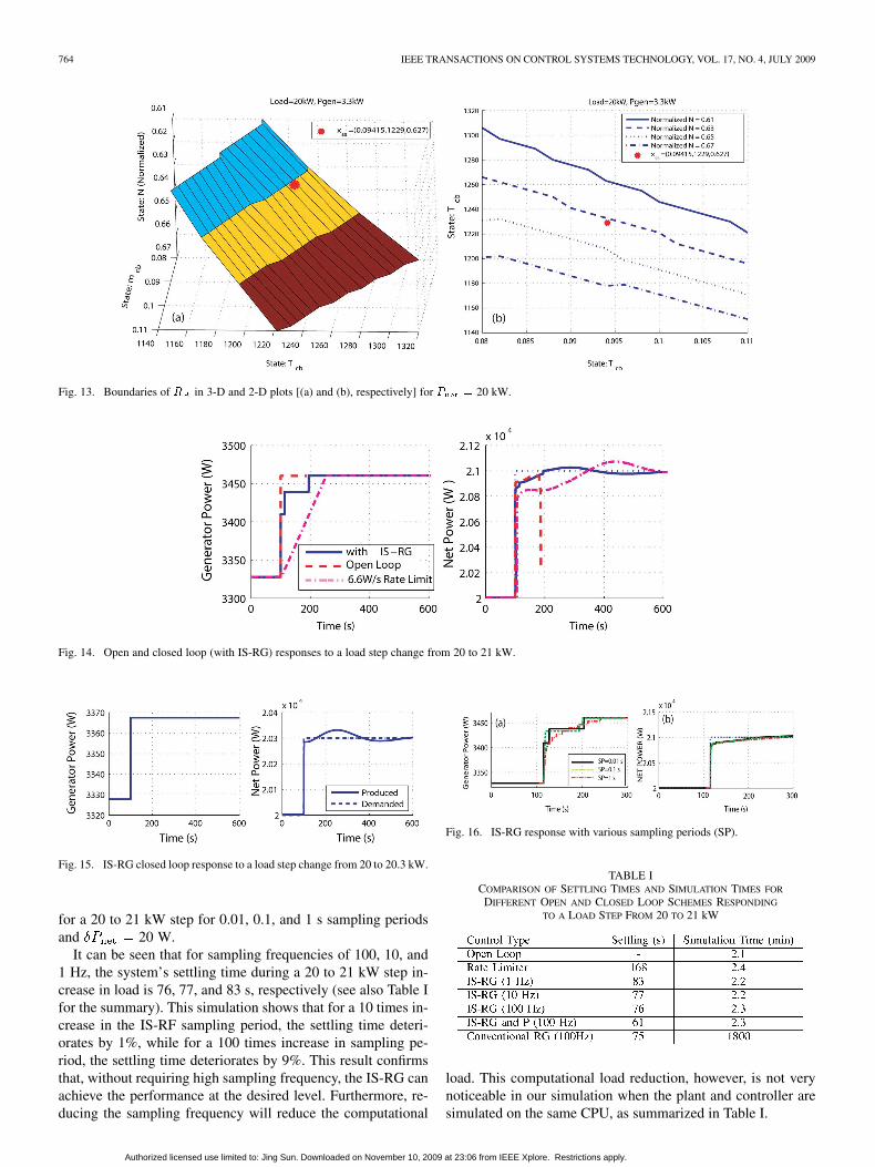
effect on the , i.e., the 55-dimension can be collapsedinto a 3-dimension . This result is also numerically verifiedfor selected load conditions. The plot for 20 kW, to-gether with the corresponding stable equilibrium point, is shownin Fig. 13, where the was calculated numerically given thenon-analytic form of the model. The boundary surface shown inFig. 13(a) divide the 3-D space into two regions, a ( , ,
) point is considered to be within the region of attraction if itis on the same side as the equilibrium point.
To better assist readers to view the plot, the 2-D plots arealso given in Fig. 13(b), with fixed as a parameter. For each
, the curve on Fig. 13(b) divides the plane into two regions:the upper-right part is within the region of attraction, while thelower-left part is outside.
The boundaries of the [i.e., each of the curves shown inFig. 13(b)] can be approximated by a linear function of the form
(17)
The parameters and are calculated for dif-ferent shaft speeds at each and are stored as lookup tables,indexed by and , for online implementation.
D. Implementation of the IS-RG for the SOFC/GT System
Utilizing the calculated offline and stored for online lookup, the IS-RG controller safeguards the system with a minimumonline computational requirement. Fig. 14 shows the simulationof the closed loop FOM with IS-RG for a 20 to 21 kW step in-crease in the desired net power, where is chosen as 20 W.Note that for the same step, the open-loop system (without theIS-RG) shuts down shortly after the step is applied (dashed linein Fig. 14), while the open loop system with a rate limiterexhibits a settling time of 168 s. The settling time achieved theIS-RG is about 76 s, which is comparable to 75 s achieved by theconventional reference governor, but it represents a significantimprovement compared to the rate limiter. The required simu-lation time for the IS-RG is 145 s compared to the 1800 min forthe conventional reference governor for this 500 s run time.
Note that the size of is set to 20 W to ensure that condi-tion (14) is met. Furthermore, note that during a 20 to 20.3 kWstep the IS-RG exhibits the same performance as the open-loopplant since the equilibrium for 20 kW belongs in the( 20.3 kW) (see Fig. 15).
It should also be noted that the main function of the IS-RG isto avoid shutdown. This is achieved by slowing down the appli-cation of the generator load to ensure safe operation. It does notattempt to change the dynamics of the system. In order to en-hance the performance, the IS-RG controller will be combinedwith a proportional controller that regulates the fuel flow intothe CB during a transient to increase the energy input into theturbine, thereby helping sustain the applied load.
E. Effects of the Sampling Period (SP)
Since the incremental step is applied whenever it is deemedfeasible by the IS-RG at each sampling instant, the sampling pe-riod of the controller will also affect the controller performanceand computational requirements for the IS-RG implementation.While fast sample may help improve the power response, it willalso increase the computational load. In this subsection, the ef-fects of the sampling period (SP) of the controller on the systemperformance will be examined to understand the tradeoffs.
In our implementation, the controller is discretized using asampler in the input (measurements) and a zero-order hold atthe output (reference command). The sampling period of thecontroller, for the simulation results shown in Figs. 14, 15, isequal to 0.01 s (i.e., 100 Hz). Fig. 16 shows the system response
Authorized licensed use limited to: Jing Sun. Downloaded on November 10, 2009 at 23:06 from IEEE Xplore. Restrictions apply.
764 IEEE TRANSACTIONS ON CONTROL SYSTEMS TECHNOLOGY, VOL. 17, NO. 4, JULY 2009
Fig. 13. Boundaries of � in 3-D and 2-D plots [(a) and (b), respectively] for � � 20 kW.
Fig. 14. Open and closed loop (with IS-RG) responses to a load step change from 20 to 21 kW.
Fig. 15. IS-RG closed loop response to a load step change from 20 to 20.3 kW.
for a 20 to 21 kW step for 0.01, 0.1, and 1 s sampling periodsand 20 W.
It can be seen that for sampling frequencies of 100, 10, and1 Hz, the system’s settling time during a 20 to 21 kW step in-crease in load is 76, 77, and 83 s, respectively (see also Table Ifor the summary). This simulation shows that for a 10 times in-crease in the IS-RF sampling period, the settling time deteri-orates by 1%, while for a 100 times increase in sampling pe-riod, the settling time deteriorates by 9%. This result confirmsthat, without requiring high sampling frequency, the IS-RG canachieve the performance at the desired level. Furthermore, re-ducing the sampling frequency will reduce the computational
Fig. 16. IS-RG response with various sampling periods (SP).
TABLE ICOMPARISON OF SETTLING TIMES AND SIMULATION TIMES FOR
DIFFERENT OPEN AND CLOSED LOOP SCHEMES RESPONDING
TO A LOAD STEP FROM 20 TO 21 kW
load. This computational load reduction, however, is not verynoticeable in our simulation when the plant and controller aresimulated on the same CPU, as summarized in Table I.
Authorized licensed use limited to: Jing Sun. Downloaded on November 10, 2009 at 23:06 from IEEE Xplore. Restrictions apply.
TSOURAPAS et al.: INCREMENTAL STEP REFERENCE GOVERNOR FOR LOAD CONDITIONING OF HYBRID FUEL CELL AND GAS TURBINE POWER PLANTS 765
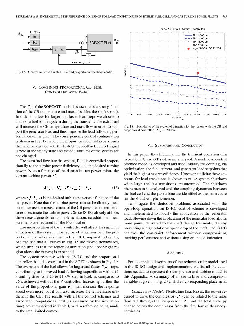
Fig. 17. Control schematic with IS-RG and proportional feedback control.
V. COMBINING PROPORTIONAL CB FUEL
CONTROLLER WITH IS-RG
The of the SOFC/GT model is shown to be a strong func-tion of the CB temperature and mass (besides the shaft speed).In order to allow for larger and faster load steps we choose toadd extra fuel to the system during the transient. The extra fuelwill increase the CB temperature and mass flow in order to sup-port the generator load and thus improve the load following per-formance of the plant. The corresponding control configurationis shown in Fig. 17, where the proportional control is used suchthat when integrated with the IS-RG, the feedback control signalis zero at the steady state and the equilibriums of the system arenot changed.
The extra fuel flow into the system, , is controlled propor-tionally to the turbine power deficiency, i.e., the desired turbinepower as a function of the demanded net power minus thecurrent turbine power
(18)
where is the desired turbine power as a function of thenet power. Note that the turbine power cannot be directly mea-sured, we use the measurement of the CB pressure and tempera-tures to estimate the turbine power. Since IS-RG already utilizesthese measurements for its implementation, no additional mea-surements are required for the P controller.
The incorporation of the controller will affect the region ofattraction of the system. The region of attraction with the pro-portional controller is shown in Fig. 18. Compared to Fig. 13,one can see that all curves in Fig. 18 are moved downwards,which implies that the region of attraction (the upper-right re-gion above the curves) is expanded.
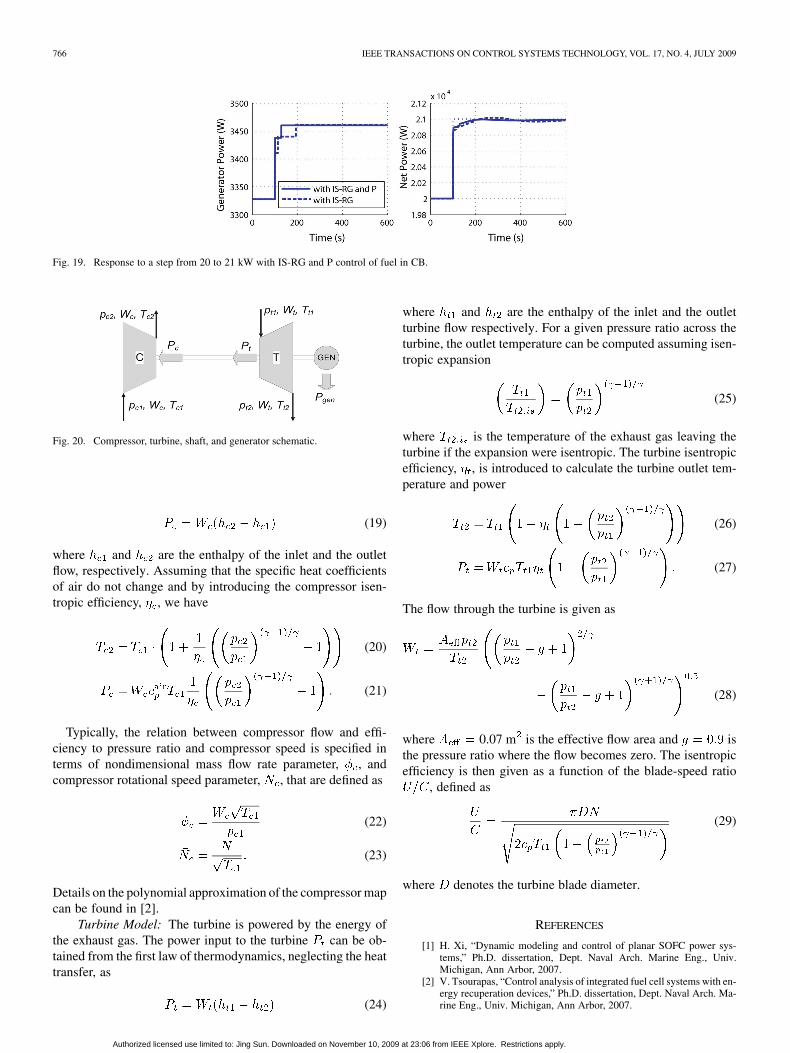
The system response with the IS-RG and the proportionalcontroller that adds extra fuel in the SOFC is shown in Fig. 19.The overshoot of the fuel allows for larger and faster steps,contributing to improved load following capabilities with a 61s settling time for a 20 to 21 kW step in load, as compared to76 s achieved without the P controller. Increasing further thevalue of the proportional gain will increase the responsespeed even more, but it will also increase the temperature gra-dient in the CB. The results with all the control schemes andassociated computational cost (as measured by the simulationtime) are summarized in Table I, with a reference being madeto the rate limited control.
Fig. 18. Boundaries of the region of attraction for the system with the CB fuelproportional controller, � � 20 kW.
VI. SUMMARY AND CONCLUSION
In this paper, the efficiency and the transient operation of ahybrid SOFC and GT system are analyzed. A nonlinear, controloriented model is developed and used initially for defining, viaoptimization, the fuel, current, and generator load setpoints thatyield the highest system efficiency. However, utilizing these set-points for load transitions is shown to cause system shutdownwhen large and fast transitions are attempted. The shutdownphenomenon is analyzed and the coupling dynamics betweenthe fuel cell and the gas turbine are identified as the main causefor the shutdown phenomenon.
To mitigate the shutdown problems associated with theopen-loop operation, an IS-RG control scheme is developedand implemented to modify the application of the generatorload. Slowing down the application of the generator load allowsmore power delivered to the shaft during transients, therebypreventing a large rotational speed drop of the shaft. The IS-RGachieves the constraint enforcement without compromisingtracking performance and without using online optimization.
APPENDIX
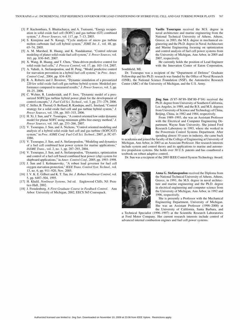
For a complete description of the reduced-order model usedin the IS-RG design and implementation, we list all the equa-tions needed to represent the compressor and turbine model inthis Appendix. A summary of all the turbine and compressorvariables is given in Fig. 20 with their corresponding placement.
Compressor Model: Neglecting heat losses, the power re-quired to drive the compressor ( ) can be related to the massflow rate through the compressor, , and the total enthalpychange across the compressor from the first law of thermody-namics as
Authorized licensed use limited to: Jing Sun. Downloaded on November 10, 2009 at 23:06 from IEEE Xplore. Restrictions apply.
766 IEEE TRANSACTIONS ON CONTROL SYSTEMS TECHNOLOGY, VOL. 17, NO. 4, JULY 2009
Fig. 19. Response to a step from 20 to 21 kW with IS-RG and P control of fuel in CB.
Fig. 20. Compressor, turbine, shaft, and generator schematic.
(19)
where and are the enthalpy of the inlet and the outletflow, respectively. Assuming that the specific heat coefficientsof air do not change and by introducing the compressor isen-tropic efficiency, , we have
(20)
(21)
Typically, the relation between compressor flow and effi-ciency to pressure ratio and compressor speed is specified interms of nondimensional mass flow rate parameter, , andcompressor rotational speed parameter, , that are defined as
(22)
(23)
Details on the polynomial approximation of the compressor mapcan be found in [2].
Turbine Model: The turbine is powered by the energy ofthe exhaust gas. The power input to the turbine can be ob-tained from the first law of thermodynamics, neglecting the heattransfer, as
(24)
where and are the enthalpy of the inlet and the outletturbine flow respectively. For a given pressure ratio across theturbine, the outlet temperature can be computed assuming isen-tropic expansion
(25)
where is the temperature of the exhaust gas leaving theturbine if the expansion were isentropic. The turbine isentropicefficiency, , is introduced to calculate the turbine outlet tem-perature and power
(26)
(27)
The flow through the turbine is given as
(28)
where 0.07 m is the effective flow area and isthe pressure ratio where the flow becomes zero. The isentropicefficiency is then given as a function of the blade-speed ratio
, defined as
(29)
where denotes the turbine blade diameter.
REFERENCES
[1] H. Xi, “Dynamic modeling and control of planar SOFC power sys-tems,” Ph.D. dissertation, Dept. Naval Arch. Marine Eng., Univ.Michigan, Ann Arbor, 2007.
[2] V. Tsourapas, “Control analysis of integrated fuel cell systems with en-ergy recuperation devices,” Ph.D. dissertation, Dept. Naval Arch. Ma-rine Eng., Univ. Michigan, Ann Arbor, 2007.
Authorized licensed use limited to: Jing Sun. Downloaded on November 10, 2009 at 23:06 from IEEE Xplore. Restrictions apply.
TSOURAPAS et al.: INCREMENTAL STEP REFERENCE GOVERNOR FOR LOAD CONDITIONING OF HYBRID FUEL CELL AND GAS TURBINE POWER PLANTS 767
[3] P. Kuchonthara, S. Bhattacharya, and A. Tsutsumi, “Energy recuper-ation in solid oxide fuel cell (SOFC) and gas turbine (GT) combinedsystem,” J. Power Sources, vol. 117, pp. 7–13, 2003.
[4] S. Kimijima and N. Kasagi, “Cycle analysis of micro gas turbinemolten carbonate fuel cell hybrid system,” JSME Int. J., vol. 48, pp.65–74, 2005.
[5] A. M. Murshed, B. Huang, and K. Nandakumar, “Control relevantmodeling of planer solid oxide fuel cell system,” J. Power Sources, vol.163, pp. 830–845, 2007.
[6] X. Wang, B. Huang, and T. Chen, “Data-driven predictive control forsolid oxide fuel cells,” J. Process Control, vol. 17, pp. 103–114, 2007.
[7] A. Vahidi, A. Stefanopoulou, and H. Peng, “Model predictive controlfor starvation prevention in a hybrid fuel cell system,” in Proc. Amer.Control Conf., 2004, pp. 834–839.
[8] R. A. Roberts and J. Brouwer, “Dynamic simulation of a pressurized220 kw solid oxide fuel-cell gas-turbine hybrid system: Modeled per-formance compared to measured results,” J. Power Sources, vol. 3, pp.18–25, 2006.
[9] C. Wchter, R. Lunderstädt, and F. Joos, “Dynamic model of a pres-surized SOFC/gas turbine hybrid power plant for the development ofcontrol concepts,” J. Fuel Cell Sci. Technol., vol. 3, pp. 271–279, 2006.
[10] C. Stiller, B. Thorud, O. Bolland, R. Kandepu, and L. Imsland, “Controlstrategy for a solid oxide fuel cell and gas turbine hybrid system,” J.Power Sources, vol. 158, pp. 303–315, 2006.
[11] H. Xi, J. Sun, and V. Tsourapas, “A control oriented low order dynamicmodel for planar SOFC using minimum gibbs free energy method,” J.Power Sources, vol. 165, pp. 253–266, 2007.
[12] V. Tsourapas, J. Sun, and A. Nickens, “Control oriented modeling andanalysis of a hybrid solid oxide fuel cell and gas turbine (SOFC/GT)system,” in Proc. ASME Conf. Fuel Cell Sci. Technol., 2007, p. FC-07-1086.
[13] V. Tsourapas, J. Sun, and A. Stefanopoulou, “Modeling and dynamicsof a fuel cell combined heat power system for marine applications,”IASME Trans., vol. 2, no. 1, pp. 287–293, 2004.
[14] V. Tsourapas, J. Sun, and A. Stefanopoulou, “Dynamics, optimizationand control of a fuel cell based combined heat power (chp) system forshipboard applications,” in Amer. Control Conf., 2005, pp. 1993–1998.
[15] J. Sun and I. Kolmanovsky, “A robust load governor for fuel celloxygen starvation protection,” IEEE Trans. Control Syst. Technol., vol.13, no. 6, pp. 911–920, Nov. 2005.
[16] I. V. K. E. Gilbert and K. T. Tan, Int. J. Robust Nonlinear Control, vol.5, pp. 6487–504, 1995.
[17] H. Khalil, Nonlinear Systems, 3rd ed. Englewood Cliffs, NJ: Pren-tice-Hall, 2002.
[18] J. Freudenberg, A First Graduate Course in Feedback Control. AnnArbor: University of Michigan, 2002, EECS 565 Coursepack.
Vasilis Tsourapas received the M.S. degree innaval architecture and marine engineering from theNational Technical University of Athens, Athens,Greece, in 2003, the M.S. degree in mechanical en-gineering and the Ph.D. degree in Naval Architectureand Marine Engineering focusing on optimizationand control analysis of fuel cell power systems fromthe University of Michigan, Ann Arbor, in 2005 and2007, respectively.
He currently holds the position of Lead Engineerwith the Innovation Center of Eaton Corporation,
Southfield, MI.Dr. Tsourapas was a recipient of the “Department of Defense” Graduate
Fellowship and his Ph.D. research was funded by the Office of Naval Research(ONR), the National Science Foundation (NSF), the Automotive ResearchCenter (ARC) of the University of Michigan, and the U.S. Army.
Jing Sun (S’87–M’89–SM’00–F’04) received thePh.D. degree from University of Southern California,Los Angeles, in 1989, and the B.S. and M.S. degreesfrom University of Science and Technology of China,Beijing, China, in 1982 and 1984, respectively.
From 1989–1993, she was an Assistant Professorwith the Electrical and Computer Engineering De-partment, Wayne State University. She joined FordResearch Laboratory in 1993, where she worked inthe Powertrain Control Systems Department. Afterspending almost 10 years in industry, she came back
to academia and joined the faculty of the College of Engineering at University ofMichigan, Ann Arbor, in 2003 as an Associate Professor. Her research interestsinclude system and control theory and its applications to marine and automo-tive propulsion systems. She holds over 30 U.S. patents and has coauthored atextbook on robust adaptive control.
Dr. Sun was a recipient of the 2003 IEEE Control System Technology Award.
Anna G. Stefanopoulou received the Diploma fromthe National Technical University of Athens, Athens,Greece, in 1991, the M.S. degree in naval architec-ture and marine engineering and the Ph.D. degreein electrical engineering and computer science fromthe University of Michigan, Ann Arbor, in 1992 and1996, respectively.
She is presently a Professor with the MechanicalEngineering Department, University of Michigan.She was an Assistant Professor (1998–2000) atthe University of California, Santa Barbara, and
a Technical Specialist (1996–1997) at the Scientific Research Laboratoriesat Ford Motor Company. Her current research interests include control ofadvanced internal combustion engines and fuel cell power systems.
Authorized licensed use limited to: Jing Sun. Downloaded on November 10, 2009 at 23:06 from IEEE Xplore. Restrictions apply.