7377 Riverside Drive Application Checklist - Dublin, Ohio,...
52
7377 Riverside Drive Application Checklist 1. Application Fee – attached 2. CD’s - attached 3. Original Signed/Notarized Application Form-attached 4. Legal Description – As Built Survey 5. List of Property Owners – Not supplied as this is an existing facility with no substantial changes being made. 6. Application Statement – Installing three new antennas with no ground work 7. Notarized Statement for Co-location – Existing Facility agreement in place. 8. 24 – Hour Emergency contact- Existing Facility agreement in place. 9. An inventory of the existing structures- Not supplied as this is an existing facility with no substantial changes being made and is just maintenance of equipment. 10. Site Plan – Attached as built. We are using the same ground layout and RAD center that already exists for Sprint. 11. Landscape Plan – Same as #10 12. Elevations- Tower Drawing as existing 13. Materials – included in CX drawings for Sprint 2.5 14. Proposed Signs – N/A no signage being added
Transcript of 7377 Riverside Drive Application Checklist - Dublin, Ohio,...

7377 Riverside Drive
Application Checklist 1. Application Fee – attached 2. CD’s - attached 3. Original Signed/Notarized Application Form-attached 4. Legal Description – As Built Survey 5. List of Property Owners – Not supplied as this is an existing facility with no substantial
changes being made. 6. Application Statement – Installing three new antennas with no ground work 7. Notarized Statement for Co-location – Existing Facility agreement in place. 8. 24 – Hour Emergency contact- Existing Facility agreement in place. 9. An inventory of the existing structures- Not supplied as this is an existing facility with no
substantial changes being made and is just maintenance of equipment. 10. Site Plan – Attached as built. We are using the same ground layout and RAD center that
already exists for Sprint. 11. Landscape Plan – Same as #10 12. Elevations- Tower Drawing as existing 13. Materials – included in CX drawings for Sprint 2.5 14. Proposed Signs – N/A no signage being added

T-1
TITLE SHEET
2.5 EQUIPMENT DEPLOYMENT
DUBLIN SCIOTO PARK
CB03XC026-D
875268
7377 RIVERSIDE DRIVEDUBLIN, OH 43017
100.0' MONOPOLE
SITE ADDRESS:
PROPERTY OWNER:
GEOGRAPHIC COORDINATES:
ZONING JURISDICTION:
CROWN DISTRICT:
POWER COMPANY:
AAV PROVIDER:
Know what's
R
N
N
REVISIONS:
ENGINEERING LICENSE:
DRAWING NOTICE:
THESE DOCUMENTS ARE CONFIDENTIAL ANDARE THE SOLE PROPERTY OF SPRINT AND MAY
NOT BE REPRODUCED, DISSEMINATED ORREDISTRIBUTED WITHOUT THE EXPRESS
WRITTEN CONSENT OF SPRINT.
Sprint6580 Sprint Parkway
Overland Park,Kansas 66251
PLANS PREPARED FOR:
PLANS PREPARED BY:
MLA PARTNER:
SHEET DESCRIPTION:
SHEET NUMBER:
SITE CASCADE:
SITE ADDRESS:
SITE NAME:
7377 RIVERSIDE DRIVE
DUBLIN, OH 43017
Phone: (812) 683-3049
PO Box 5 318 North Main Street
Huntingburg, Indiana 47542
WWebb
Approved

”
”
” ”
”
”
”
SP-1
SPRINT
SPECIFICATIONS
REVISIONS:
ENGINEERING LICENSE:
DRAWING NOTICE:
THESE DOCUMENTS ARE CONFIDENTIAL ANDARE THE SOLE PROPERTY OF SPRINT AND MAY
NOT BE REPRODUCED, DISSEMINATED ORREDISTRIBUTED WITHOUT THE EXPRESS
WRITTEN CONSENT OF SPRINT.
Sprint6580 Sprint Parkway
Overland Park,Kansas 66251
PLANS PREPARED FOR:
PLANS PREPARED BY:
MLA PARTNER:
SHEET DESCRIPTION:
SHEET NUMBER:
SITE CASCADE:
SITE ADDRESS:
SITE NAME:
7377 RIVERSIDE DRIVE
DUBLIN, OH 43017
Phone: (812) 683-3049
PO Box 5 318 North Main Street
Huntingburg, Indiana 47542
SP-2
SPRINT
SPECIFICATIONS

REVISIONS:
ENGINEERING LICENSE:
DRAWING NOTICE:
THESE DOCUMENTS ARE CONFIDENTIAL ANDARE THE SOLE PROPERTY OF SPRINT AND MAY
NOT BE REPRODUCED, DISSEMINATED ORREDISTRIBUTED WITHOUT THE EXPRESS
WRITTEN CONSENT OF SPRINT.
Sprint6580 Sprint Parkway
Overland Park,Kansas 66251
PLANS PREPARED FOR:
PLANS PREPARED BY:
MLA PARTNER:
SHEET DESCRIPTION:
SHEET NUMBER:
SITE CASCADE:
SITE ADDRESS:
SITE NAME:
7377 RIVERSIDE DRIVE
DUBLIN, OH 43017
Phone: (812) 683-3049
PO Box 5 318 North Main Street
Huntingburg, Indiana 47542
SITE PLAN
SEE GRAPHIC SCALE BAR AND LABEL
A-1
SITE PLAN
1

A-2
TOWER ELEVATIONS &
ANTENNA DETAILS
EXISTING ANTENNA & RRU LAYOUT
SCALE: N.T.S.
N
FINAL ANTENNA & RRU LAYOUT
SCALE: N.T.S.
REVISIONS:
ENGINEERING LICENSE:
DRAWING NOTICE:
THESE DOCUMENTS ARE CONFIDENTIAL ANDARE THE SOLE PROPERTY OF SPRINT AND MAY
NOT BE REPRODUCED, DISSEMINATED ORREDISTRIBUTED WITHOUT THE EXPRESS
WRITTEN CONSENT OF SPRINT.
Sprint6580 Sprint Parkway
Overland Park,Kansas 66251
PLANS PREPARED FOR:
PLANS PREPARED BY:
MLA PARTNER:
SHEET DESCRIPTION:
SHEET NUMBER:
SITE CASCADE:
SITE ADDRESS:
SITE NAME:
7377 RIVERSIDE DRIVE
DUBLIN, OH 43017
Phone: (812) 683-3049
PO Box 5 318 North Main Street
Huntingburg, Indiana 47542
FINAL TOWER ELEVATION
SCALE: N.T.S.
3
2
1
N

2.5 RRU DETAIL
SCALE: N.T.S.
2.5 ANTENNA DETAIL
SCALE: N.T.S.
ANTENNA MOUNT DETAIL
SCALE: N.T.S.
SCALE: N.T.S.
1 2
3
1
ANTENNA MOUNT DETAIL
SCALE: N.T.S.
ANTENNA & HYBRID
CABLE DETAILS
REVISIONS:
ENGINEERING LICENSE:
DRAWING NOTICE:
THESE DOCUMENTS ARE CONFIDENTIAL ANDARE THE SOLE PROPERTY OF SPRINT AND MAY
NOT BE REPRODUCED, DISSEMINATED ORREDISTRIBUTED WITHOUT THE EXPRESS
WRITTEN CONSENT OF SPRINT.
Sprint6580 Sprint Parkway
Overland Park,Kansas 66251
PLANS PREPARED FOR:
PLANS PREPARED BY:
MLA PARTNER:
SHEET DESCRIPTION:
SHEET NUMBER:
SITE CASCADE:
SITE ADDRESS:
SITE NAME:
7377 RIVERSIDE DRIVE
DUBLIN, OH 43017
Phone: (812) 683-3049
PO Box 5 318 North Main Street
Huntingburg, Indiana 47542
A-3

HYBRID BREAKOUT DETAIL
SCALE: N.T.S.
1
43
SCALE: N.T.S.
EXISTING OUTDOOR MMBS CABINET
SCALE: N.T.S.
SCALE: N.T.S.
2
BREAKOUT &
EQUIPMENT DETAILS
REVISIONS:
ENGINEERING LICENSE:
DRAWING NOTICE:
THESE DOCUMENTS ARE CONFIDENTIAL ANDARE THE SOLE PROPERTY OF SPRINT AND MAY
NOT BE REPRODUCED, DISSEMINATED ORREDISTRIBUTED WITHOUT THE EXPRESS
WRITTEN CONSENT OF SPRINT.
Sprint6580 Sprint Parkway
Overland Park,Kansas 66251
PLANS PREPARED FOR:
PLANS PREPARED BY:
MLA PARTNER:
SHEET DESCRIPTION:
SHEET NUMBER:
SITE CASCADE:
SITE ADDRESS:
SITE NAME:
7377 RIVERSIDE DRIVE
DUBLIN, OH 43017
Phone: (812) 683-3049
PO Box 5 318 North Main Street
Huntingburg, Indiana 47542
A-4

1
TWO HOLE LUG
SCALE: N.T.S.
SCALE: N.T.S.
ANTENNA GROUNDING PLAN
SCALE: N.T.S.
EQUIPMENT GROUNDING PLAN
SEE GRAPHIC SCALE BAR & LABEL
GROUNDING RISER DIAGRAM
SCALE: N.T.S.
2 3
4 5
REVISIONS:
ENGINEERING LICENSE:
DRAWING NOTICE:
THESE DOCUMENTS ARE CONFIDENTIAL ANDARE THE SOLE PROPERTY OF SPRINT AND MAY
NOT BE REPRODUCED, DISSEMINATED ORREDISTRIBUTED WITHOUT THE EXPRESS
WRITTEN CONSENT OF SPRINT.
Sprint6580 Sprint Parkway
Overland Park,Kansas 66251
PLANS PREPARED FOR:
PLANS PREPARED BY:
MLA PARTNER:
SHEET DESCRIPTION:
SHEET NUMBER:
SITE CASCADE:
SITE ADDRESS:
SITE NAME:
7377 RIVERSIDE DRIVE
DUBLIN, OH 43017
Phone: (812) 683-3049
PO Box 5 318 North Main Street
Huntingburg, Indiana 47542
GROUNDING DETAILS
E-1
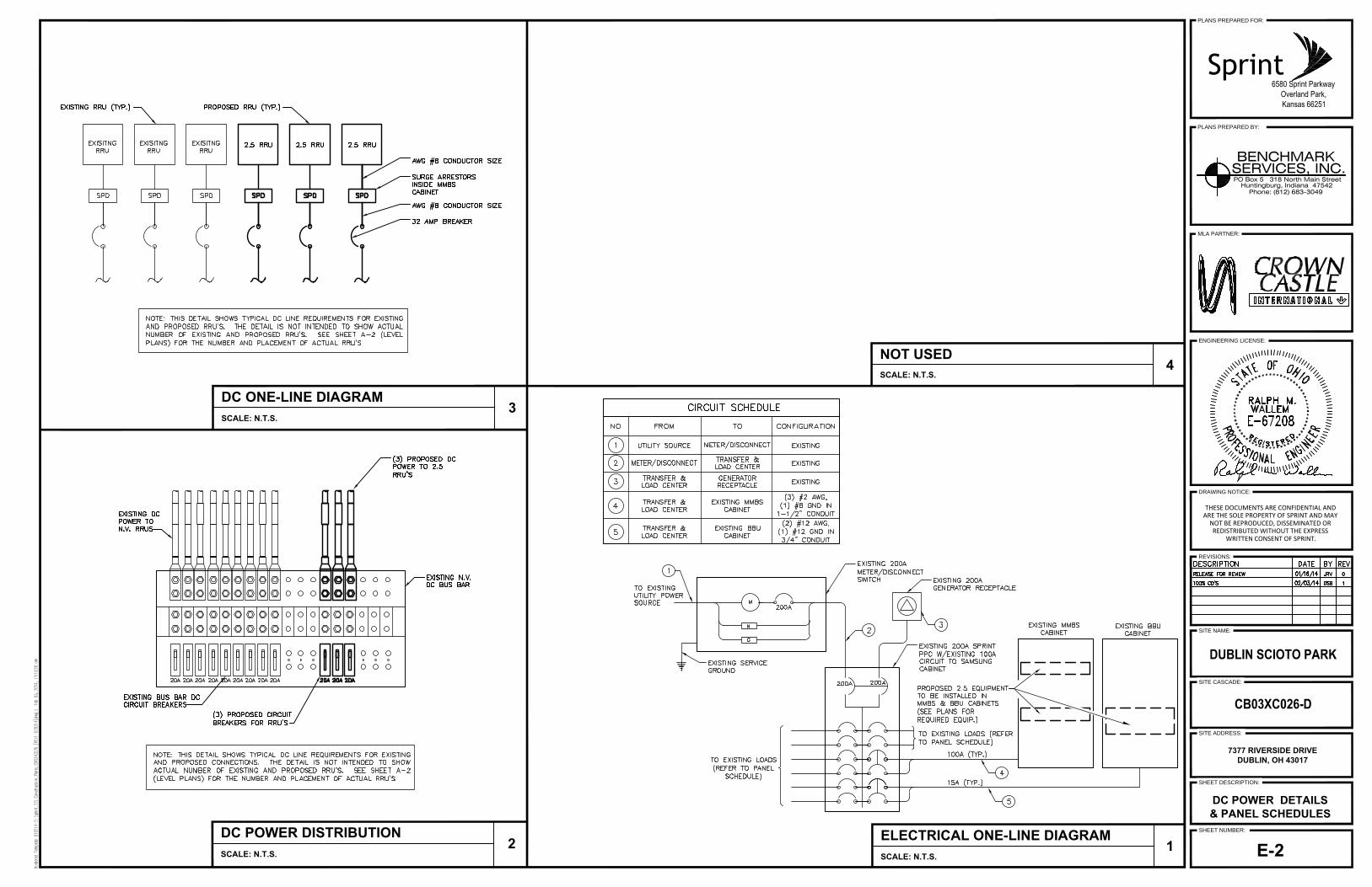
DC POWER DISTRIBUTION
SCALE: N.T.S.
DC ONE-LINE DIAGRAM
SCALE: N.T.S.
NOT USED
SCALE: N.T.S.
4
3
2
ELECTRICAL ONE-LINE DIAGRAM
SCALE: N.T.S.
1
REVISIONS:
ENGINEERING LICENSE:
DRAWING NOTICE:
THESE DOCUMENTS ARE CONFIDENTIAL ANDARE THE SOLE PROPERTY OF SPRINT AND MAY
NOT BE REPRODUCED, DISSEMINATED ORREDISTRIBUTED WITHOUT THE EXPRESS
WRITTEN CONSENT OF SPRINT.
Sprint6580 Sprint Parkway
Overland Park,Kansas 66251
PLANS PREPARED FOR:
PLANS PREPARED BY:
MLA PARTNER:
SHEET DESCRIPTION:
SHEET NUMBER:
SITE CASCADE:
SITE ADDRESS:
SITE NAME:
7377 RIVERSIDE DRIVE
DUBLIN, OH 43017
Phone: (812) 683-3049
PO Box 5 318 North Main Street
Huntingburg, Indiana 47542
DC POWER DETAILS
& PANEL SCHEDULES
E-2


December 06, 2013 100 Ft Monopole Tower Structural Analysis CCI BU No 875268 Project Number OH-0083-B, Application 206097, Revision 2 Page 2
tnxTower Report - version 6.1.3.1
TABLE OF CONTENTS 1) INTRODUCTION 2) ANALYSIS CRITERIA Table 1 - Proposed Antenna and Cable Information Table 2 - Existing Antenna and Cable Information Table 3 - Design Antenna and Cable Information 3) ANALYSIS PROCEDURE Table 4 - Documents Provided 3.1) Analysis Method 3.2) Assumptions 4) ANALYSIS RESULTS Table 5 - Section Capacity (Summary) Table 6 – Tower Components vs. Capacity 4.1) Recommendations 5) APPENDIX A tnxTower Output 6) APPENDIX B Base Level Drawing 7) APPENDIX C Additional Calculations

December 06, 2013 100 Ft Monopole Tower Structural Analysis CCI BU No 875268 Project Number OH-0083-B, Application 206097, Revision 2 Page 3
tnxTower Report - version 6.1.3.1
1) INTRODUCTION This tower is a 100ft Monopole tower designed by VALMONT in October of 1998. The tower was originally designed for a wind speed of 80 mph per TIA/EIA-222-F. 2) ANALYSIS CRITERIA The structural analysis was performed for this tower in accordance with the requirements of TIA-222-G Structural Standards for Steel Antenna Towers and Antenna Supporting Structures using a 3-second gust wind speed of 90 mph with no ice, 40 mph with 0.75 inch ice thickness and 60 mph under service loads, exposure category C.
Table 1 - Proposed Antenna and Cable Information
Mounting Level (ft)
Center Line
Elevation (ft)
Number of
Antennas
Antenna Manufacturer
Antenna Model Number of Feed Lines
Feed Line
Size (in) Note
96.0 97.0
3 kmw
communications ET-X-TS-70-15-62-18-iR-
RD w/ Mount Pipe
3 1-5/8 -
3 kmw
communications ET-X-WM-18-65-8P
w/ Mount Pipe
3 samsung
telecommunications 2.5G 8T8R RADAR
FILTER
3 samsung
telecommunications 2.5GHz RRH-V3
3 samsung
telecommunications OPTIC FIBER JUNCTION
CYLINDER
3 samsung
telecommunications POWER JUNCTION
CYLINDER
3 samsung
telecommunications RRH-C2A w/EXT FILTER
3 samsung
telecommunications RRH-P4
Table 2 - Existing Antenna and Cable Information
Mounting Level (ft)
Center Line
Elevation (ft)
Number of
Antennas
Antenna Manufacturer
Antenna Model Number of Feed Lines
Feed Line
Size (in) Note
100.0 100.0 1 miscl Valmont 1 Tree Pole
Branch - - 1
96.0
97.0 3 ems wireless FV65-14-00NA2 w/ Mount Pipe
6 7/8 2
96.0
1 tower mounts Miscellaneous [NA 502-1]
- - 1 1 tower mounts
Side Arm Mount [SO 701-3]
86.5 86.5 1 miscl Valmont 1 Tree Pole
Branch - - 1
83.5 83.5 1 miscl Valmont 1 Tree Pole
Branch - - 1
80.5 80.5 1 miscl Valmont 1 Tree Pole
Branch - - 1

December 06, 2013 100 Ft Monopole Tower Structural Analysis CCI BU No 875268 Project Number OH-0083-B, Application 206097, Revision 2 Page 4
tnxTower Report - version 6.1.3.1
Mounting Level (ft)
Center Line
Elevation (ft)
Number of
Antennas
Antenna Manufacturer
Antenna Model Number of Feed Lines
Feed Line
Size (in) Note
80.0 80.0 1 tower mounts Miscellaneous [NA 502-1] - - 3
77.5 77.5 1 miscl Valmont 1 Tree Pole
Branch - - 1
74.5 74.5 1 miscl Valmont 1 Tree Pole
Branch - - 1
70.0 70.0 1 miscl Valmont 1 Tree Pole
Branch - - 1
Notes: 1) Existing Equipment 2) Equipment to Be Removed was not considered in this analysis. 3) Empty Mount
Table 3 - Design Antenna and Cable Information
Mounting Level (ft)
Center Line
Elevation (ft)
Number of
Antennas
Antenna Manufacturer
Antenna Model Number of Feed Lines
Feed Line
Size (in)
100 100 1 Generic Tree Pole Branches and
Antenna top group - -
86.5 86.5 1 Generic Tree Pole Branches - -
83.5 83.5 1 Generic Tree Pole Branches - -
80.5 80.5 1 Generic Tree Pole Branches - -
77.5 77.5 1 Generic Tree Pole Branches - -
74.5 74.5 1 Generic Tree Pole Branches - -
70 70 1 Generic Tree Pole Branches - -
3) ANALYSIS PROCEDURE
Table 4 - Documents Provided
Document Remarks Reference Source
4-GEOTECHNICAL REPORTS G2 Consulting Group,
Project #98512A 1517280 CCISITES
4-TOWER FOUNDATION DRAWINGS/DESIGN/SPECS
G2 Consulting Group, Project #98512A
1432890 CCISITES
4-TOWER MANUFACTURER DRAWINGS
Valmont, Order #17946-98 1518356 CCISITES
4-TOWER STRUCTURAL ANALYSIS REPORTS
Selective Site Consultants, Project #OH-0083-A
3485246 CCISITES
3.1) Analysis Method
tnxTower (version 6.1.3.1), a commercially available analysis software package, was used to create a three-dimensional model of the tower and calculate member stresses for various loading cases. Selected output from the analysis is included in Appendix A.

December 06, 2013 100 Ft Monopole Tower Structural Analysis CCI BU No 875268 Project Number OH-0083-B, Application 206097, Revision 2 Page 5
tnxTower Report - version 6.1.3.1
3.2) Assumptions
1) Tower and structures were built in accordance with the manufacturer’s specifications. 2) The tower and structures have been maintained in accordance with the manufacturer’s
specification. 3) The configuration of antennas, transmission cables, mounts and other appurtenances are as
specified in Tables 1 and 2 and the referenced drawings. This analysis may be affected if any assumptions are not valid or have been made in error. Selective Site Consultants should be notified to determine the effect on the structural integrity of the tower.
4) ANALYSIS RESULTS
Table 5 - Section Capacity (Summary)
Section No. Elevation (ft) Component Type Size Critical
Element P (K) SF*P_allow (K)
% Capacity Pass / Fail
L1 100 - 49.5833 Pole TP26.4x17.06x0.281 1 -8.19 1669.45 66.0 Pass
L2 49.5833 - 0 Pole TP35x25.0198x0.406 2 -18.77 3333.57 73.0 Pass
Summary
Pole (L2) 73.0 Pass
RATING = 73.0 Pass
Table 6 - Tower Component Stresses vs. Capacity – LC5
Notes Component Elevation (ft) % Capacity Pass / Fail
1 Anchor Rods 0 63.1 Pass
1 Base Plate 0 38.9 Pass
1 Base Foundation 0 32.1 Pass
1 Base Foundation Soil Interaction
0 25.6 Pass
Structure Rating (max from all components) = 73.0%
Notes: 1) See additional documentation in “Appendix C – Additional Calculations” for calculations supporting the % capacity
consumed. 4.1) Recommendations
The tower and its foundation have sufficient capacity to carry the existing and proposed loads. No modifications are required at this time.

December 06, 2013 100 Ft Monopole Tower Structural Analysis CCI BU No 875268 Project Number OH-0083-B, Application 206097, Revision 2 Page 6
tnxTower Report - version 6.1.3.1
APPENDIX A
TNXTOWER OUTPUT

Selective Site Consultants
9900 W 109th Street Suite 300
Overland Park, Kansas 66210 Phone: (913)-438-7700
FAX: (913)-438-7777
Job: OH-0083-B, Dublin Scioto Park, BU #875268
Project: 100ft Monopine Client: Crown Castle Drawn by: bsisk App'd:
Code: TIA-222-G Date: 12/06/13 Scale: NTS Path:
O:\Tower Analysis\OH-0083\OH-0083-B\tnx analysis\OH-0083-B (G).eri Dwg No. E-1
100.0 ft
49.6 ft
0.0 ft
REACTIONS - 90 mph WIND
23 KSHEAR
1696 kip-ftMOMENT
19 K
AXIAL
40 mph WIND - 0.7500 in ICE
3 K
SHEAR
265 kip-ft
MOMENT
34 KAXIAL
ARE FACTOREDALL REACTIONS
S
ection
12
Length
(ft)
50.4
254.0
0
N
um
ber
of S
ides
12
12
T
hic
kness (
in)
0.2
810
0.4
060
S
ocket Length
(ft)
4.4
2
T
op D
ia (
in)
17.0
600
25.0
198
B
ot D
ia (
in)
26.4
000
35.0
000
G
rade
A572-6
5
W
eig
ht (K
)3.3
7.1
10.4
Valmont 1 Tree Pole Branch 100 ET-X-WM-18-65-8P w/ Mount Pipe 96 2.5G 8T8R RADAR FILTER 96 2.5GHz RRH-V3 96 OPTIC FIBER JUNCTION CYLINDER 96 POWER JUNCTION CYLINDER 96 RRH-C2A w/EXT FILTER 96 RRH-P4 96 ET-X-TS-70-15-62-18-iR-RD w/ Mount Pipe
96 ET-X-WM-18-65-8P w/ Mount Pipe 96 2.5G 8T8R RADAR FILTER 96 2.5GHz RRH-V3 96 OPTIC FIBER JUNCTION CYLINDER 96 POWER JUNCTION CYLINDER 96 RRH-C2A w/EXT FILTER 96 RRH-P4 96 ET-X-TS-70-15-62-18-iR-RD w/ Mount Pipe
96 ET-X-WM-18-65-8P w/ Mount Pipe 96 2.5G 8T8R RADAR FILTER 96 2.5GHz RRH-V3 96 OPTIC FIBER JUNCTION CYLINDER 96 POWER JUNCTION CYLINDER 96 RRH-C2A w/EXT FILTER 96 RRH-P4 96 Side Arm Mount [SO 701-3] 96 Miscellaneous [NA 502-1] 96 ET-X-TS-70-15-62-18-iR-RD w/ Mount Pipe
96 Valmont 1 Tree Pole Branch 86.5 Valmont 1 Tree Pole Branch 83.5 Valmont 1 Tree Pole Branch 80.5 Miscellaneous [NA 502-1] 80 Valmont 1 Tree Pole Branch 77.5 Valmont 1 Tree Pole Branch 74.5 Valmont 1 Tree Pole Branch 70DESIGNED APPURTENANCE LOADING
TYPE TYPEELEVATION ELEVATION Valmont 1 Tree Pole Branch 100
ET-X-WM-18-65-8P w/ Mount Pipe 96
2.5G 8T8R RADAR FILTER 96
2.5GHz RRH-V3 96
OPTIC FIBER JUNCTION CYLINDER 96
POWER JUNCTION CYLINDER 96
RRH-C2A w/EXT FILTER 96
RRH-P4 96
ET-X-TS-70-15-62-18-iR-RD w/ Mount Pipe
96
ET-X-WM-18-65-8P w/ Mount Pipe 96
2.5G 8T8R RADAR FILTER 96
2.5GHz RRH-V3 96
OPTIC FIBER JUNCTION CYLINDER 96
POWER JUNCTION CYLINDER 96
RRH-C2A w/EXT FILTER 96
RRH-P4 96
ET-X-TS-70-15-62-18-iR-RD w/ Mount Pipe
96
ET-X-WM-18-65-8P w/ Mount Pipe 96
2.5G 8T8R RADAR FILTER 96
2.5GHz RRH-V3 96
OPTIC FIBER JUNCTION CYLINDER 96
POWER JUNCTION CYLINDER 96
RRH-C2A w/EXT FILTER 96
RRH-P4 96
Side Arm Mount [SO 701-3] 96
Miscellaneous [NA 502-1] 96
ET-X-TS-70-15-62-18-iR-RD w/ Mount Pipe
96
Valmont 1 Tree Pole Branch 86.5
Valmont 1 Tree Pole Branch 83.5
Valmont 1 Tree Pole Branch 80.5
Miscellaneous [NA 502-1] 80
Valmont 1 Tree Pole Branch 77.5
Valmont 1 Tree Pole Branch 74.5
Valmont 1 Tree Pole Branch 70
MATERIAL STRENGTHGRADE GRADEFy FyFu Fu
A572-65 65 ksi 80 ksi
TOWER DESIGN NOTES1. Tower is located in Franklin County, Ohio.2. Tower designed for Exposure C to the TIA-222-G Standard.3. Tower designed for a 90 mph basic wind in accordance with the TIA-222-G Standard.4. Tower is also designed for a 40 mph basic wind with 0.75 in ice. Ice is considered to increase
in thickness with height.5. Deflections are based upon a 60 mph wind.6. Tower Structure Class II.7. Topographic Category 1 with Crest Height of 0.00 ft8. TOWER RATING: 73%

December 06, 2013 100 Ft Monopole Tower Structural Analysis CCI BU No 875268 Project Number OH-0083-B, Application 206097, Revision 2 Page 7
tnxTower Report - version 6.1.3.1
Tower Input Data There is a pole section. This tower is designed using the TIA-222-G standard. The following design criteria apply:
Tower is located in Franklin County, Ohio. Basic wind speed of 90 mph. Structure Class II. Exposure Category C. Topographic Category 1. Crest Height 0.00 ft. Nominal ice thickness of 0.7500 in. Ice thickness is considered to increase with height. Ice density of 56pcf. A wind speed of 40 mph is used in combination with ice. Temperature drop of 60 °F. Deflections calculated using a wind speed of 60 mph. A non-linear (P-delta) analysis was used. Pressures are calculated at each section. Stress ratio used in pole design is 1. Local bending stresses due to climbing loads, feed line supports, and appurtenance mounts are not
considered.
Options
Consider Moments - Legs Distribute Leg Loads As Uniform Treat Feedline Bundles As Cylinder
Consider Moments - Horizontals Assume Legs Pinned Use ASCE 10 X-Brace Ly Rules
Consider Moments - Diagonals √ Assume Rigid Index Plate Calculate Redundant Bracing Forces
Use Moment Magnification √ Use Clear Spans For Wind Area Ignore Redundant Members in FEA
√ Use Code Stress Ratios Use Clear Spans For KL/r SR Leg Bolts Resist Compression
√ Use Code Safety Factors - Guys Retension Guys To Initial Tension All Leg Panels Have Same Allowable
Escalate Ice √ Bypass Mast Stability Checks Offset Girt At Foundation
Always Use Max Kz √ Use Azimuth Dish Coefficients √ Consider Feedline Torque
Use Special Wind Profile √ Project Wind Area of Appurt. Include Angle Block Shear Check
Include Bolts In Member Capacity Autocalc Torque Arm Areas Poles
Leg Bolts Are At Top Of Section SR Members Have Cut Ends √ Include Shear-Torsion Interaction
Secondary Horizontal Braces Leg Sort Capacity Reports By Component Always Use Sub-Critical Flow
Use Diamond Inner Bracing (4 Sided) Triangulate Diamond Inner Bracing Use Top Mounted Sockets
Add IBC .6D+W Combination Use TIA-222-G Tension Splice
Capacity Exemption
Tapered Pole Section Geometry
Section Elevation
ft
Section
Length
ft
Splice
Length
ft
Number
of
Sides
Top
Diameter
in
Bottom
Diameter
in
Wall
Thickness
in
Bend
Radius
in
Pole Grade
L1 100.00-49.58 50.42 4.42 12 17.0600 26.4000 0.2810 1.1240 A572-65
(65 ksi)
L2 49.58-0.00 54.00 12 25.0198 35.0000 0.4060 1.6240 A572-65
(65 ksi)

December 06, 2013 100 Ft Monopole Tower Structural Analysis CCI BU No 875268 Project Number OH-0083-B, Application 206097, Revision 2 Page 8
tnxTower Report - version 6.1.3.1
Tapered Pole Properties
Section Tip Dia.
in
Area
in2
I
in4
r
in
C
in
I/C
in3
J
in4
It/Q
in2
w
in
w/t
L1 17.6618 15.1820 545.5648 6.0069 8.8371 61.7359 1105.4623 7.4721 3.8190 13.591
27.3313 23.6330 2057.8693 9.3506 13.6752 150.4818 4169.8010 11.6314 6.3221 22.499
L2 26.7475 32.1781 2488.3019 8.8117 12.9602 191.9949 5041.9742 15.8371 5.6172 13.836
36.2347 45.2254 6908.2842 12.3847 18.1300 381.0416 13998.056
8
22.2586 8.2919 20.423
Tower
Elevation
ft
Gusset
Area
(per face)
ft2
Gusset
Thickness
in
Gusset Grade Adjust. Factor
Af
Adjust.
Factor
Ar
Weight Mult.
Double Angle
Stitch Bolt
Spacing
Diagonals
in
Double Angle
Stitch Bolt
Spacing
Horizontals
in
L1 100.00-
49.58
1 1 1
L2 49.58-0.00 1 1 1
Feed Line/Linear Appurtenances - Entered As Area
Description Face
or
Leg
Allow
Shield
Component
Type
Placement
ft
Total
Number
CAAA
ft2/ft
Weight
plf
*96*
TYPE 7( 1 5/8'') A No Inside Pole 96.00 - 0.00 3 No Ice
1/2'' Ice
1'' Ice
0.00
0.00
0.00
2.20
2.20
2.20
Feed Line/Linear Appurtenances Section Areas
Tower
Sectio
n
Tower
Elevation
ft
Face AR
ft2
AF
ft2
CAAA
In Face
ft2
CAAA
Out Face
ft2
Weight
K
L1 100.00-49.58 A
B
C
0.000
0.000
0.000
0.000
0.000
0.000
0.000
0.000
0.000
0.000
0.000
0.000
0.31
0.00
0.00
L2 49.58-0.00 A
B
C
0.000
0.000
0.000
0.000
0.000
0.000
0.000
0.000
0.000
0.000
0.000
0.000
0.33
0.00
0.00
Feed Line/Linear Appurtenances Section Areas - With Ice
Tower
Sectio
n
Tower
Elevation
ft
Face
or
Leg
Ice
Thickness
in
AR
ft2
AF
ft2
CAAA
In Face
ft2
CAAA
Out Face
ft2
Weight
K
L1 100.00-49.58 A
B
C
1.625 0.000
0.000
0.000
0.000
0.000
0.000
0.000
0.000
0.000
0.000
0.000
0.000
0.31
0.00
0.00
L2 49.58-0.00 A
B
C
1.457 0.000
0.000
0.000
0.000
0.000
0.000
0.000
0.000
0.000
0.000
0.000
0.000
0.33
0.00
0.00

December 06, 2013 100 Ft Monopole Tower Structural Analysis CCI BU No 875268 Project Number OH-0083-B, Application 206097, Revision 2 Page 9
tnxTower Report - version 6.1.3.1
Feed Line Center of Pressure
Section Elevation
ft
CPX
in
CPZ
in
CPX
Ice
in
CPZ
Ice
in
L1 100.00-49.58 0.0000 0.0000 0.0000 0.0000
L2 49.58-0.00 0.0000 0.0000 0.0000 0.0000
Shielding Factor Ka
Tower
Section
Feed Line
Record No.
Description Feed Line
Segment
Elev.
Ka
No Ice
Ka
Ice
Discrete Tower Loads
Description Face
or
Leg
Offset
Type
Offsets:
Horz
Lateral
Vert
ft
ft
ft
Azimuth
Adjustmen
t
°
Placement
ft
CAAA
Front
ft2
CAAA
Side
ft2
Weight
K
*96*
*Sector A*
ET-X-TS-70-15-62-18-iR-
RD w/ Mount Pipe
A From Leg 3.00
0.00
1.00
0.0000 96.00 No Ice
1/2''
Ice
1'' Ice
8.70
9.37
10.00
6.49
7.69
8.62
0.07
0.13
0.21
ET-X-WM-18-65-8P w/
Mount Pipe
A From Leg 3.00
0.00
1.00
0.0000 96.00 No Ice
1/2''
Ice
1'' Ice
7.35
7.92
8.46
4.43
5.32
6.08
0.06
0.11
0.17
2.5G 8T8R RADAR
FILTER
A From Leg 3.00
0.00
1.00
0.0000 96.00 No Ice
1/2''
Ice
1'' Ice
0.94
1.08
1.22
0.35
0.46
0.57
0.02
0.03
0.04
2.5GHz RRH-V3 A From Leg 3.00
0.00
1.00
0.0000 96.00 No Ice
1/2''
Ice
1'' Ice
2.80
3.03
3.26
1.42
1.59
1.76
0.06
0.08
0.10
OPTIC FIBER JUNCTION
CYLINDER
A From Leg 3.00
0.00
1.00
0.0000 96.00 No Ice
1/2''
Ice
1'' Ice
0.45
0.55
0.67
0.45
0.55
0.67
0.00
0.01
0.01
POWER JUNCTION
CYLINDER
A From Leg 3.00
0.00
1.00
0.0000 96.00 No Ice
1/2''
Ice
1'' Ice
0.43
0.53
0.64
0.43
0.53
0.64
0.00
0.01
0.01
RRH-C2A w/EXT FILTER A From Leg 3.00
0.00
1.00
0.0000 96.00 No Ice
1/2''
Ice
1'' Ice
3.09
3.35
3.61
5.54
5.86
6.19
0.05
0.09
0.13
RRH-P4 A From Leg 3.00
0.00
1.00
0.0000 96.00 No Ice
1/2''
Ice
1'' Ice
3.19
3.44
3.70
2.07
2.29
2.52
0.06
0.08
0.11
*Sector B*
ET-X-TS-70-15-62-18-iR-
RD w/ Mount Pipe
B From Leg 3.00
0.00
0.0000 96.00 No Ice
1/2''
8.70
9.37
6.49
7.69
0.07
0.13

December 06, 2013 100 Ft Monopole Tower Structural Analysis CCI BU No 875268 Project Number OH-0083-B, Application 206097, Revision 2 Page 10
tnxTower Report - version 6.1.3.1
Description Face
or
Leg
Offset
Type
Offsets:
Horz
Lateral
Vert
ft
ft
ft
Azimuth
Adjustmen
t
°
Placement
ft
CAAA
Front
ft2
CAAA
Side
ft2
Weight
K
1.00 Ice
1'' Ice
10.00 8.62 0.21
ET-X-WM-18-65-8P w/
Mount Pipe
B From Leg 3.00
0.00
1.00
0.0000 96.00 No Ice
1/2''
Ice
1'' Ice
7.35
7.92
8.46
4.43
5.32
6.08
0.06
0.11
0.17
2.5G 8T8R RADAR
FILTER
B From Leg 3.00
0.00
1.00
0.0000 96.00 No Ice
1/2''
Ice
1'' Ice
0.94
1.08
1.22
0.35
0.46
0.57
0.02
0.03
0.04
2.5GHz RRH-V3 B From Leg 3.00
0.00
1.00
0.0000 96.00 No Ice
1/2''
Ice
1'' Ice
2.80
3.03
3.26
1.42
1.59
1.76
0.06
0.08
0.10
OPTIC FIBER JUNCTION
CYLINDER
B From Leg 3.00
0.00
1.00
0.0000 96.00 No Ice
1/2''
Ice
1'' Ice
0.45
0.55
0.67
0.45
0.55
0.67
0.00
0.01
0.01
POWER JUNCTION
CYLINDER
B From Leg 3.00
0.00
1.00
0.0000 96.00 No Ice
1/2''
Ice
1'' Ice
0.43
0.53
0.64
0.43
0.53
0.64
0.00
0.01
0.01
RRH-C2A w/EXT FILTER B From Leg 3.00
0.00
1.00
0.0000 96.00 No Ice
1/2''
Ice
1'' Ice
3.09
3.35
3.61
5.54
5.86
6.19
0.05
0.09
0.13
RRH-P4 B From Leg 3.00
0.00
1.00
0.0000 96.00 No Ice
1/2''
Ice
1'' Ice
3.19
3.44
3.70
2.07
2.29
2.52
0.06
0.08
0.11
*Sector C*
ET-X-TS-70-15-62-18-iR-
RD w/ Mount Pipe
C From Leg 3.00
0.00
1.00
0.0000 96.00 No Ice
1/2''
Ice
1'' Ice
8.70
9.37
10.00
6.49
7.69
8.62
0.07
0.13
0.21
ET-X-WM-18-65-8P w/
Mount Pipe
C From Leg 3.00
0.00
1.00
0.0000 96.00 No Ice
1/2''
Ice
1'' Ice
7.35
7.92
8.46
4.43
5.32
6.08
0.06
0.11
0.17
2.5G 8T8R RADAR
FILTER
C From Leg 3.00
0.00
1.00
0.0000 96.00 No Ice
1/2''
Ice
1'' Ice
0.94
1.08
1.22
0.35
0.46
0.57
0.02
0.03
0.04
2.5GHz RRH-V3 C From Leg 3.00
0.00
1.00
0.0000 96.00 No Ice
1/2''
Ice
1'' Ice
2.80
3.03
3.26
1.42
1.59
1.76
0.06
0.08
0.10
OPTIC FIBER JUNCTION
CYLINDER
C From Leg 3.00
0.00
1.00
0.0000 96.00 No Ice
1/2''
Ice
1'' Ice
0.45
0.55
0.67
0.45
0.55
0.67
0.00
0.01
0.01
POWER JUNCTION
CYLINDER
C From Leg 3.00
0.00
1.00
0.0000 96.00 No Ice
1/2''
Ice
1'' Ice
0.43
0.53
0.64
0.43
0.53
0.64
0.00
0.01
0.01
RRH-C2A w/EXT FILTER C From Leg 3.00 0.0000 96.00 No Ice 3.09 5.54 0.05

December 06, 2013 100 Ft Monopole Tower Structural Analysis CCI BU No 875268 Project Number OH-0083-B, Application 206097, Revision 2 Page 11
tnxTower Report - version 6.1.3.1
Description Face
or
Leg
Offset
Type
Offsets:
Horz
Lateral
Vert
ft
ft
ft
Azimuth
Adjustmen
t
°
Placement
ft
CAAA
Front
ft2
CAAA
Side
ft2
Weight
K
0.00
1.00
1/2''
Ice
1'' Ice
3.35
3.61
5.86
6.19
0.09
0.13
RRH-P4 C From Leg 3.00
0.00
1.00
0.0000 96.00 No Ice
1/2''
Ice
1'' Ice
3.19
3.44
3.70
2.07
2.29
2.52
0.06
0.08
0.11
Side Arm Mount [SO 701-
3]
C None 0.0000 96.00 No Ice
1/2''
Ice
1'' Ice
2.83
3.92
5.01
2.83
3.92
5.01
0.20
0.24
0.28
Miscellaneous [NA 502-1] C None 0.0000 96.00 No Ice
1/2''
Ice
1'' Ice
11.44
15.96
20.48
11.44
15.96
20.48
0.66
0.81
0.95
*80*
*Empty Mount*
Miscellaneous [NA 502-1] C None 0.0000 80.00 No Ice
1/2''
Ice
1'' Ice
11.44
15.96
20.48
11.44
15.96
20.48
0.66
0.81
0.95
*misc*
Valmont 1 Tree Pole
Branch
C None 0.0000 100.00 No Ice
1/2''
Ice
1'' Ice
37.00
37.00
37.00
37.00
37.00
37.00
0.30
0.57
0.84
Valmont 1 Tree Pole
Branch
C None 0.0000 86.50 No Ice
1/2''
Ice
1'' Ice
37.00
37.00
37.00
37.00
37.00
37.00
0.30
0.57
0.84
Valmont 1 Tree Pole
Branch
C None 0.0000 83.50 No Ice
1/2''
Ice
1'' Ice
37.00
37.00
37.00
37.00
37.00
37.00
0.30
0.57
0.84
Valmont 1 Tree Pole
Branch
C None 0.0000 80.50 No Ice
1/2''
Ice
1'' Ice
37.00
37.00
37.00
37.00
37.00
37.00
0.30
0.57
0.84
Valmont 1 Tree Pole
Branch
C None 0.0000 77.50 No Ice
1/2''
Ice
1'' Ice
37.00
37.00
37.00
37.00
37.00
37.00
0.30
0.57
0.84
Valmont 1 Tree Pole
Branch
C None 0.0000 74.50 No Ice
1/2''
Ice
1'' Ice
37.00
37.00
37.00
37.00
37.00
37.00
0.30
0.57
0.84
Valmont 1 Tree Pole
Branch
C None 0.0000 70.00 No Ice
1/2''
Ice
1'' Ice
37.00
37.00
37.00
37.00
37.00
37.00
0.30
0.57
0.84
December 06, 2013 100 Ft Monopole Tower Structural Analysis CCI BU No 875268 Project Number OH-0083-B, Application 206097, Revision 2 Page 12
tnxTower Report - version 6.1.3.1
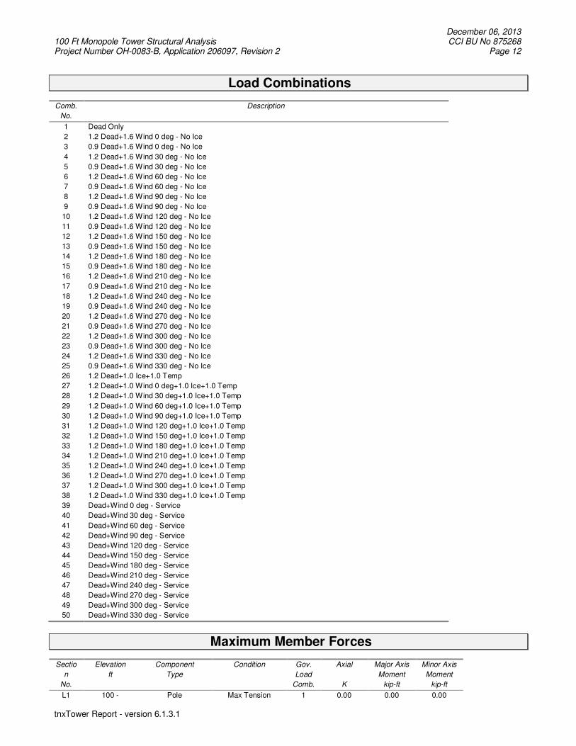
Load Combinations
Comb.
No.
Description
1 Dead Only
2 1.2 Dead+1.6 Wind 0 deg - No Ice
3 0.9 Dead+1.6 Wind 0 deg - No Ice
4 1.2 Dead+1.6 Wind 30 deg - No Ice
5 0.9 Dead+1.6 Wind 30 deg - No Ice
6 1.2 Dead+1.6 Wind 60 deg - No Ice
7 0.9 Dead+1.6 Wind 60 deg - No Ice
8 1.2 Dead+1.6 Wind 90 deg - No Ice
9 0.9 Dead+1.6 Wind 90 deg - No Ice
10 1.2 Dead+1.6 Wind 120 deg - No Ice
11 0.9 Dead+1.6 Wind 120 deg - No Ice
12 1.2 Dead+1.6 Wind 150 deg - No Ice
13 0.9 Dead+1.6 Wind 150 deg - No Ice
14 1.2 Dead+1.6 Wind 180 deg - No Ice
15 0.9 Dead+1.6 Wind 180 deg - No Ice
16 1.2 Dead+1.6 Wind 210 deg - No Ice
17 0.9 Dead+1.6 Wind 210 deg - No Ice
18 1.2 Dead+1.6 Wind 240 deg - No Ice
19 0.9 Dead+1.6 Wind 240 deg - No Ice
20 1.2 Dead+1.6 Wind 270 deg - No Ice
21 0.9 Dead+1.6 Wind 270 deg - No Ice
22 1.2 Dead+1.6 Wind 300 deg - No Ice
23 0.9 Dead+1.6 Wind 300 deg - No Ice
24 1.2 Dead+1.6 Wind 330 deg - No Ice
25 0.9 Dead+1.6 Wind 330 deg - No Ice
26 1.2 Dead+1.0 Ice+1.0 Temp
27 1.2 Dead+1.0 Wind 0 deg+1.0 Ice+1.0 Temp
28 1.2 Dead+1.0 Wind 30 deg+1.0 Ice+1.0 Temp
29 1.2 Dead+1.0 Wind 60 deg+1.0 Ice+1.0 Temp
30 1.2 Dead+1.0 Wind 90 deg+1.0 Ice+1.0 Temp
31 1.2 Dead+1.0 Wind 120 deg+1.0 Ice+1.0 Temp
32 1.2 Dead+1.0 Wind 150 deg+1.0 Ice+1.0 Temp
33 1.2 Dead+1.0 Wind 180 deg+1.0 Ice+1.0 Temp
34 1.2 Dead+1.0 Wind 210 deg+1.0 Ice+1.0 Temp
35 1.2 Dead+1.0 Wind 240 deg+1.0 Ice+1.0 Temp
36 1.2 Dead+1.0 Wind 270 deg+1.0 Ice+1.0 Temp
37 1.2 Dead+1.0 Wind 300 deg+1.0 Ice+1.0 Temp
38 1.2 Dead+1.0 Wind 330 deg+1.0 Ice+1.0 Temp
39 Dead+Wind 0 deg - Service
40 Dead+Wind 30 deg - Service
41 Dead+Wind 60 deg - Service
42 Dead+Wind 90 deg - Service
43 Dead+Wind 120 deg - Service
44 Dead+Wind 150 deg - Service
45 Dead+Wind 180 deg - Service
46 Dead+Wind 210 deg - Service
47 Dead+Wind 240 deg - Service
48 Dead+Wind 270 deg - Service
49 Dead+Wind 300 deg - Service
50 Dead+Wind 330 deg - Service
Maximum Member Forces
Sectio
n
No.
Elevation
ft
Component
Type
Condition Gov.
Load
Comb.
Axial
K
Major Axis
Moment
kip-ft
Minor Axis
Moment
kip-ft
L1 100 - Pole Max Tension 1 0.00 0.00 0.00

December 06, 2013 100 Ft Monopole Tower Structural Analysis CCI BU No 875268 Project Number OH-0083-B, Application 206097, Revision 2 Page 13
tnxTower Report - version 6.1.3.1
Sectio
n
No.
Elevation
ft
Component
Type
Condition Gov.
Load
Comb.
Axial
K
Major Axis
Moment
kip-ft
Minor Axis
Moment
kip-ft
49.5833
Max. Compression 26 -21.43 0.00 0.00
Max. Mx 8 -8.19 -561.54 0.00
Max. My 2 -8.19 0.00 561.54
Max. Vy 8 18.88 -561.54 0.00
Max. Vx 2 -18.88 0.00 561.54
Max. Torque 12 0.00
L2 49.5833 - 0 Pole Max Tension 1 0.00 0.00 0.00
Max. Compression 26 -34.16 0.00 0.00
Max. Mx 8 -18.77 -1695.61 0.00
Max. My 14 -18.77 0.00 -1695.61
Max. Vy 8 22.92 -1695.61 0.00
Max. Vx 2 -22.92 0.00 1695.61
Max. Torque 12 0.00
Maximum Reactions
Location Condition Gov.
Load
Comb.
Vertical
K
Horizontal, X
K
Horizontal, Z
K
Pole Max. Vert 27 34.16 0.00 3.48
Max. Hx 20 18.80 22.89 0.00
Max. Hz 2 18.80 0.00 22.89
Max. Mx 2 1695.61 0.00 22.89
Max. Mz 8 1695.61 -22.89 0.00
Max. Torsion 12 0.00 -11.44 -19.82
Min. Vert 11 14.10 -19.82 -11.44
Min. Hx 8 18.80 -22.89 0.00
Min. Hz 14 18.80 0.00 -22.89
Min. Mx 14 -1695.61 0.00 -22.89
Min. Mz 20 -1695.61 22.89 0.00
Min. Torsion 16 -0.00 11.44 -19.82
Tower Mast Reaction Summary
Load
Combination
Vertical
K
Shearx
K
Shearz
K
Overturning
Moment, Mx kip-ft
Overturning
Moment, Mz kip-ft
Torque
kip-ft
Dead Only 15.67 0.00 0.00 0.00 0.00 0.00
1.2 Dead+1.6 Wind 0 deg -
No Ice
18.80 0.00 -22.89 -1695.61 0.00 0.00
0.9 Dead+1.6 Wind 0 deg -
No Ice
14.10 0.00 -22.89 -1684.09 0.00 0.00
1.2 Dead+1.6 Wind 30 deg -
No Ice
18.80 11.44 -19.82 -1468.45 -847.81 0.00
0.9 Dead+1.6 Wind 30 deg -
No Ice
14.10 11.44 -19.82 -1458.46 -842.04 0.00
1.2 Dead+1.6 Wind 60 deg -
No Ice
18.80 19.82 -11.44 -847.81 -1468.45 -0.00
0.9 Dead+1.6 Wind 60 deg -
No Ice
14.10 19.82 -11.44 -842.04 -1458.46 -0.00
1.2 Dead+1.6 Wind 90 deg -
No Ice
18.80 22.89 0.00 0.00 -1695.61 0.00
0.9 Dead+1.6 Wind 90 deg -
No Ice
14.10 22.89 0.00 0.00 -1684.09 0.00
1.2 Dead+1.6 Wind 120 deg 18.80 19.82 11.44 847.81 -1468.45 0.00

December 06, 2013 100 Ft Monopole Tower Structural Analysis CCI BU No 875268 Project Number OH-0083-B, Application 206097, Revision 2 Page 14
tnxTower Report - version 6.1.3.1
Load
Combination
Vertical
K
Shearx
K
Shearz
K
Overturning
Moment, Mx kip-ft
Overturning
Moment, Mz kip-ft
Torque
kip-ft
- No Ice
0.9 Dead+1.6 Wind 120 deg
- No Ice
14.10 19.82 11.44 842.04 -1458.46 0.00
1.2 Dead+1.6 Wind 150 deg
- No Ice
18.80 11.44 19.82 1468.45 -847.81 -0.00
0.9 Dead+1.6 Wind 150 deg
- No Ice
14.10 11.44 19.82 1458.46 -842.04 -0.00
1.2 Dead+1.6 Wind 180 deg
- No Ice
18.80 0.00 22.89 1695.61 0.00 0.00
0.9 Dead+1.6 Wind 180 deg
- No Ice
14.10 0.00 22.89 1684.09 0.00 0.00
1.2 Dead+1.6 Wind 210 deg
- No Ice
18.80 -11.44 19.82 1468.45 847.81 0.00
0.9 Dead+1.6 Wind 210 deg
- No Ice
14.10 -11.44 19.82 1458.46 842.04 0.00
1.2 Dead+1.6 Wind 240 deg
- No Ice
18.80 -19.82 11.44 847.81 1468.45 -0.00
0.9 Dead+1.6 Wind 240 deg
- No Ice
14.10 -19.82 11.44 842.04 1458.46 -0.00
1.2 Dead+1.6 Wind 270 deg
- No Ice
18.80 -22.89 0.00 0.00 1695.61 0.00
0.9 Dead+1.6 Wind 270 deg
- No Ice
14.10 -22.89 0.00 0.00 1684.09 0.00
1.2 Dead+1.6 Wind 300 deg
- No Ice
18.80 -19.82 -11.44 -847.81 1468.45 0.00
0.9 Dead+1.6 Wind 300 deg
- No Ice
14.10 -19.82 -11.44 -842.04 1458.46 0.00
1.2 Dead+1.6 Wind 330 deg
- No Ice
18.80 -11.44 -19.82 -1468.45 847.81 -0.00
0.9 Dead+1.6 Wind 330 deg
- No Ice
14.10 -11.44 -19.82 -1458.46 842.04 -0.00
1.2 Dead+1.0 Ice+1.0 Temp 34.16 0.00 0.00 0.00 0.00 0.00
1.2 Dead+1.0 Wind 0
deg+1.0 Ice+1.0 Temp
34.16 0.00 -3.48 -265.34 0.00 0.00
1.2 Dead+1.0 Wind 30
deg+1.0 Ice+1.0 Temp
34.16 1.74 -3.01 -229.79 -132.67 0.00
1.2 Dead+1.0 Wind 60
deg+1.0 Ice+1.0 Temp
34.16 3.01 -1.74 -132.67 -229.79 -0.00
1.2 Dead+1.0 Wind 90
deg+1.0 Ice+1.0 Temp
34.16 3.48 0.00 0.00 -265.34 0.00
1.2 Dead+1.0 Wind 120
deg+1.0 Ice+1.0 Temp
34.16 3.01 1.74 132.67 -229.79 0.00
1.2 Dead+1.0 Wind 150
deg+1.0 Ice+1.0 Temp
34.16 1.74 3.01 229.79 -132.67 -0.00
1.2 Dead+1.0 Wind 180
deg+1.0 Ice+1.0 Temp
34.16 0.00 3.48 265.34 0.00 0.00
1.2 Dead+1.0 Wind 210
deg+1.0 Ice+1.0 Temp
34.16 -1.74 3.01 229.79 132.67 0.00
1.2 Dead+1.0 Wind 240
deg+1.0 Ice+1.0 Temp
34.16 -3.01 1.74 132.67 229.79 -0.00
1.2 Dead+1.0 Wind 270
deg+1.0 Ice+1.0 Temp
34.16 -3.48 0.00 0.00 265.34 0.00
1.2 Dead+1.0 Wind 300
deg+1.0 Ice+1.0 Temp
34.16 -3.01 -1.74 -132.67 229.79 0.00
1.2 Dead+1.0 Wind 330
deg+1.0 Ice+1.0 Temp
34.16 -1.74 -3.01 -229.79 132.67 -0.00
Dead+Wind 0 deg - Service 15.67 0.00 -5.69 -420.16 0.00 0.00
Dead+Wind 30 deg - Service 15.67 2.84 -4.93 -363.87 -210.08 0.00
Dead+Wind 60 deg - Service 15.67 4.93 -2.84 -210.08 -363.87 -0.00
Dead+Wind 90 deg - Service 15.67 5.69 0.00 0.00 -420.16 0.00

December 06, 2013 100 Ft Monopole Tower Structural Analysis CCI BU No 875268 Project Number OH-0083-B, Application 206097, Revision 2 Page 15
tnxTower Report - version 6.1.3.1
Load
Combination
Vertical
K
Shearx
K
Shearz
K
Overturning
Moment, Mx kip-ft
Overturning
Moment, Mz kip-ft
Torque
kip-ft
Dead+Wind 120 deg -
Service
15.67 4.93 2.84 210.08 -363.87 0.00
Dead+Wind 150 deg -
Service
15.67 2.84 4.93 363.87 -210.08 -0.00
Dead+Wind 180 deg -
Service
15.67 0.00 5.69 420.16 0.00 0.00
Dead+Wind 210 deg -
Service
15.67 -2.84 4.93 363.87 210.08 0.00
Dead+Wind 240 deg -
Service
15.67 -4.93 2.84 210.08 363.87 -0.00
Dead+Wind 270 deg -
Service
15.67 -5.69 0.00 0.00 420.16 0.00
Dead+Wind 300 deg -
Service
15.67 -4.93 -2.84 -210.08 363.87 0.00
Dead+Wind 330 deg -
Service
15.67 -2.84 -4.93 -363.87 210.08 -0.00
Solution Summary
Load
Comb.
Sum of Applied Forces Sum of Reactions
% Error PX
K
PY
K
PZ
K
PX
K
PY
K
PZ
K
1 0.00 -15.67 0.00 0.00 15.67 0.00 0.000%
2 0.00 -18.80 -22.89 0.00 18.80 22.89 0.000%
3 0.00 -14.10 -22.89 0.00 14.10 22.89 0.000%
4 11.44 -18.80 -19.82 -11.44 18.80 19.82 0.000%
5 11.44 -14.10 -19.82 -11.44 14.10 19.82 0.000%
6 19.82 -18.80 -11.44 -19.82 18.80 11.44 0.000%
7 19.82 -14.10 -11.44 -19.82 14.10 11.44 0.000%
8 22.89 -18.80 0.00 -22.89 18.80 0.00 0.000%
9 22.89 -14.10 0.00 -22.89 14.10 0.00 0.000%
10 19.82 -18.80 11.44 -19.82 18.80 -11.44 0.000%
11 19.82 -14.10 11.44 -19.82 14.10 -11.44 0.000%
12 11.44 -18.80 19.82 -11.44 18.80 -19.82 0.000%
13 11.44 -14.10 19.82 -11.44 14.10 -19.82 0.000%
14 0.00 -18.80 22.89 0.00 18.80 -22.89 0.000%
15 0.00 -14.10 22.89 0.00 14.10 -22.89 0.000%
16 -11.44 -18.80 19.82 11.44 18.80 -19.82 0.000%
17 -11.44 -14.10 19.82 11.44 14.10 -19.82 0.000%
18 -19.82 -18.80 11.44 19.82 18.80 -11.44 0.000%
19 -19.82 -14.10 11.44 19.82 14.10 -11.44 0.000%
20 -22.89 -18.80 0.00 22.89 18.80 0.00 0.000%
21 -22.89 -14.10 0.00 22.89 14.10 0.00 0.000%
22 -19.82 -18.80 -11.44 19.82 18.80 11.44 0.000%
23 -19.82 -14.10 -11.44 19.82 14.10 11.44 0.000%
24 -11.44 -18.80 -19.82 11.44 18.80 19.82 0.000%
25 -11.44 -14.10 -19.82 11.44 14.10 19.82 0.000%
26 0.00 -34.16 0.00 0.00 34.16 0.00 0.000%
27 0.00 -34.16 -3.48 0.00 34.16 3.48 0.000%
28 1.74 -34.16 -3.01 -1.74 34.16 3.01 0.000%
29 3.01 -34.16 -1.74 -3.01 34.16 1.74 0.000%
30 3.48 -34.16 0.00 -3.48 34.16 0.00 0.000%
31 3.01 -34.16 1.74 -3.01 34.16 -1.74 0.000%
32 1.74 -34.16 3.01 -1.74 34.16 -3.01 0.000%
33 0.00 -34.16 3.48 0.00 34.16 -3.48 0.000%
34 -1.74 -34.16 3.01 1.74 34.16 -3.01 0.000%
35 -3.01 -34.16 1.74 3.01 34.16 -1.74 0.000%
36 -3.48 -34.16 0.00 3.48 34.16 0.00 0.000%

December 06, 2013 100 Ft Monopole Tower Structural Analysis CCI BU No 875268 Project Number OH-0083-B, Application 206097, Revision 2 Page 16
tnxTower Report - version 6.1.3.1
Load
Comb.
Sum of Applied Forces Sum of Reactions
% Error PX
K
PY
K
PZ
K
PX
K
PY
K
PZ
K
37 -3.01 -34.16 -1.74 3.01 34.16 1.74 0.000%
38 -1.74 -34.16 -3.01 1.74 34.16 3.01 0.000%
39 0.00 -15.67 -5.69 0.00 15.67 5.69 0.000%
40 2.84 -15.67 -4.93 -2.84 15.67 4.93 0.000%
41 4.93 -15.67 -2.84 -4.93 15.67 2.84 0.000%
42 5.69 -15.67 0.00 -5.69 15.67 0.00 0.000%
43 4.93 -15.67 2.84 -4.93 15.67 -2.84 0.000%
44 2.84 -15.67 4.93 -2.84 15.67 -4.93 0.000%
45 0.00 -15.67 5.69 0.00 15.67 -5.69 0.000%
46 -2.84 -15.67 4.93 2.84 15.67 -4.93 0.000%
47 -4.93 -15.67 2.84 4.93 15.67 -2.84 0.000%
48 -5.69 -15.67 0.00 5.69 15.67 0.00 0.000%
49 -4.93 -15.67 -2.84 4.93 15.67 2.84 0.000%
50 -2.84 -15.67 -4.93 2.84 15.67 4.93 0.000%
Non-Linear Convergence Results
Load
Combination
Converged? Number
of Cycles
Displacement
Tolerance
Force
Tolerance
1 Yes 4 0.00000001 0.00000001
2 Yes 4 0.00000001 0.00004886
3 Yes 4 0.00000001 0.00001225
4 Yes 5 0.00000001 0.00011231
5 Yes 5 0.00000001 0.00004172
6 Yes 5 0.00000001 0.00011231
7 Yes 5 0.00000001 0.00004172
8 Yes 4 0.00000001 0.00004886
9 Yes 4 0.00000001 0.00001225
10 Yes 5 0.00000001 0.00011231
11 Yes 5 0.00000001 0.00004172
12 Yes 5 0.00000001 0.00011231
13 Yes 5 0.00000001 0.00004172
14 Yes 4 0.00000001 0.00004886
15 Yes 4 0.00000001 0.00001225
16 Yes 5 0.00000001 0.00011231
17 Yes 5 0.00000001 0.00004172
18 Yes 5 0.00000001 0.00011231
19 Yes 5 0.00000001 0.00004172
20 Yes 4 0.00000001 0.00004886
21 Yes 4 0.00000001 0.00001225
22 Yes 5 0.00000001 0.00011231
23 Yes 5 0.00000001 0.00004172
24 Yes 5 0.00000001 0.00011231
25 Yes 5 0.00000001 0.00004172
26 Yes 4 0.00000001 0.00000001
27 Yes 4 0.00000001 0.00060028
28 Yes 4 0.00000001 0.00067117
29 Yes 4 0.00000001 0.00067117
30 Yes 4 0.00000001 0.00060028
31 Yes 4 0.00000001 0.00067117
32 Yes 4 0.00000001 0.00067117
33 Yes 4 0.00000001 0.00060028
34 Yes 4 0.00000001 0.00067117
35 Yes 4 0.00000001 0.00067117
36 Yes 4 0.00000001 0.00060028
37 Yes 4 0.00000001 0.00067117
38 Yes 4 0.00000001 0.00067117
39 Yes 4 0.00000001 0.00000001
December 06, 2013 100 Ft Monopole Tower Structural Analysis CCI BU No 875268 Project Number OH-0083-B, Application 206097, Revision 2 Page 17
tnxTower Report - version 6.1.3.1
40 Yes 4 0.00000001 0.00011298
41 Yes 4 0.00000001 0.00011298
42 Yes 4 0.00000001 0.00000001
43 Yes 4 0.00000001 0.00011298
44 Yes 4 0.00000001 0.00011298
45 Yes 4 0.00000001 0.00000001
46 Yes 4 0.00000001 0.00011298
47 Yes 4 0.00000001 0.00011298
48 Yes 4 0.00000001 0.00000001
49 Yes 4 0.00000001 0.00011298
50 Yes 4 0.00000001 0.00011298
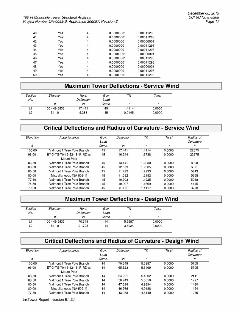
Maximum Tower Deflections - Service Wind
Section
No.
Elevation
ft
Horz.
Deflection
in
Gov.
Load
Comb.
Tilt
°
Twist
°
L1 100 - 49.5833 17.441 45 1.4114 0.0000
L2 54 - 0 5.383 45 0.9145 0.0000
Critical Deflections and Radius of Curvature - Service Wind
Elevation
ft
Appurtenance Gov.
Load
Comb.
Deflection
in
Tilt
°
Twist
°
Radius of
Curvature
ft
100.00 Valmont 1 Tree Pole Branch 45 17.441 1.4114 0.0000 22675
96.00 ET-X-TS-70-15-62-18-iR-RD w/
Mount Pipe
45 16.244 1.3738 0.0000 22675
86.50 Valmont 1 Tree Pole Branch 45 13.441 1.2830 0.0000 8398
83.50 Valmont 1 Tree Pole Branch 45 12.579 1.2535 0.0000 6871
80.50 Valmont 1 Tree Pole Branch 45 11.732 1.2233 0.0000 5813
80.00 Miscellaneous [NA 502-1] 45 11.592 1.2182 0.0000 5668
77.50 Valmont 1 Tree Pole Branch 45 10.903 1.1925 0.0000 5038
74.50 Valmont 1 Tree Pole Branch 45 10.097 1.1609 0.0000 4445
70.00 Valmont 1 Tree Pole Branch 45 8.933 1.1117 0.0000 3778
Maximum Tower Deflections - Design Wind
Section
No.
Elevation
ft
Horz.
Deflection
in
Gov.
Load
Comb.
Tilt
°
Twist
°
L1 100 - 49.5833 70.349 14 5.6987 0.0000
L2 54 - 0 21.725 14 3.6924 0.0000
Critical Deflections and Radius of Curvature - Design Wind
Elevation
ft
Appurtenance Gov.
Load
Comb.
Deflection
in
Tilt
°
Twist
°
Radius of
Curvature
ft
100.00 Valmont 1 Tree Pole Branch 14 70.349 5.6987 0.0000 5705
96.00 ET-X-TS-70-15-62-18-iR-RD w/
Mount Pipe
14 65.523 5.5469 0.0000 5705
86.50 Valmont 1 Tree Pole Branch 14 54.221 5.1802 0.0000 2111
83.50 Valmont 1 Tree Pole Branch 14 50.743 5.0610 0.0000 1727
80.50 Valmont 1 Tree Pole Branch 14 47.328 4.9394 0.0000 1460
80.00 Miscellaneous [NA 502-1] 14 46.766 4.9188 0.0000 1424
77.50 Valmont 1 Tree Pole Branch 14 43.988 4.8149 0.0000 1265
December 06, 2013 100 Ft Monopole Tower Structural Analysis CCI BU No 875268 Project Number OH-0083-B, Application 206097, Revision 2 Page 18
tnxTower Report - version 6.1.3.1
Elevation
ft
Appurtenance Gov.
Load
Comb.
Deflection
in
Tilt
°
Twist
°
Radius of
Curvature
ft
74.50 Valmont 1 Tree Pole Branch 14 40.735 4.6872 0.0000 1115
70.00 Valmont 1 Tree Pole Branch 14 36.042 4.4885 0.0000 947
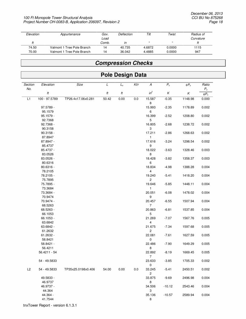
Compression Checks
Pole Design Data
Section
No.
Elevation
ft
Size
L
ft
Lu
ft
Kl/r
A
in2
Pu
K
φPn
K
Ratio
Pu
φPn
L1 100 - 97.5789 TP26.4x17.06x0.281 50.42 0.00 0.0 15.587
8
-0.35 1148.98 0.000
97.5789 -
95.1579
15.993
6
-2.35 1178.89 0.002
95.1579 -
92.7368
16.399
5
-2.52 1208.80 0.002
92.7368 -
90.3158
16.805
3
-2.68 1238.72 0.002
90.3158 -
87.8947
17.211
1
-2.86 1268.63 0.002
87.8947 -
85.4737
17.616
9
-3.24 1298.54 0.002
85.4737 -
83.0526
18.022
8
-3.63 1328.46 0.003
83.0526 -
80.6316
18.428
6
-3.82 1358.37 0.003
80.6316 -
78.2105
18.834
4
-4.98 1388.28 0.004
78.2105 -
75.7895
19.240
2
-5.41 1418.20 0.004
75.7895 -
73.3684
19.646
1
-5.85 1448.11 0.004
73.3684 -
70.9474
20.051
9
-6.08 1478.02 0.004
70.9474 -
68.5263
20.457
7
-6.55 1507.94 0.004
68.5263 -
66.1053
20.863
5
-6.81 1537.85 0.004
66.1053 -
63.6842
21.269
4
-7.07 1567.76 0.005
63.6842 -
61.2632
21.675
2
-7.34 1597.68 0.005
61.2632 -
58.8421
22.081
0
-7.61 1627.59 0.005
58.8421 -
56.4211
22.486
8
-7.90 1649.29 0.005
56.4211 - 54 22.892
7
-8.19 1669.45 0.005
54 - 49.5833 23.633
0
-3.85 1705.33 0.002
L2 54 - 49.5833 TP35x25.0198x0.406 54.00 0.00 0.0 33.245
2
-5.41 2450.51 0.002
49.5833 -
46.9737
33.875
8
-9.69 2496.98 0.004
46.9737 -
44.364
34.506
3
-10.12 2543.46 0.004
44.364 -
41.7544
35.136
8
-10.57 2589.94 0.004

December 06, 2013 100 Ft Monopole Tower Structural Analysis CCI BU No 875268 Project Number OH-0083-B, Application 206097, Revision 2 Page 19
tnxTower Report - version 6.1.3.1
Section
No.
Elevation
ft
Size
L
ft
Lu
ft
Kl/r
A
in2
Pu
K
φPn
K
Ratio
Pu
φPn
41.7544 -
39.1447
35.767
4
-11.02 2636.41 0.004
39.1447 -
36.5351
36.397
9
-11.48 2682.89 0.004
36.5351 -
33.9254
37.028
5
-11.94 2729.37 0.004
33.9254 -
31.3158
37.659
0
-12.42 2775.84 0.004
31.3158 -
28.7061
38.289
5
-12.90 2822.32 0.005
28.7061 -
26.0965
38.920
1
-13.40 2868.80 0.005
26.0965 -
23.4868
39.550
6
-13.90 2915.27 0.005
23.4868 -
20.8772
40.181
1
-14.41 2961.75 0.005
20.8772 -
18.2675
40.811
7
-14.93 3008.23 0.005
18.2675 -
15.6579
41.442
2
-15.45 3054.71 0.005
15.6579 -
13.0482
42.072
7
-15.98 3101.18 0.005
13.0482 -
10.4386
42.703
3
-16.53 3147.66 0.005
10.4386 -
7.82895
43.333
8
-17.07 3194.14 0.005
7.82895 -
5.2193
43.964
4
-17.63 3240.61 0.005
5.2193 -
2.60965
44.594
9
-18.19 3287.09 0.006
2.60965 - 0 45.225
4
-18.77 3333.57 0.006
Pole Bending Design Data
Section
No.
Elevation
ft
Size
Mux
kip-ft
φMnx
kip-ft
Ratio
Mux
φMnx
Muy
kip-ft
φMny
kip-ft
Ratio
Muy
φMny
L1 100 - 97.5789 TP26.4x17.06x0.281 4.21 399.93 0.011 0.00 399.93 0.000
97.5789 -
95.1579
14.73 421.19 0.035 0.00 421.19 0.000
95.1579 -
92.7368
28.64 443.01 0.065 0.00 443.01 0.000
92.7368 -
90.3158
42.99 465.38 0.092 0.00 465.38 0.000
90.3158 -
87.8947
57.78 488.30 0.118 0.00 488.30 0.000
87.8947 -
85.4737
74.66 511.77 0.146 0.00 511.77 0.000
85.4737 -
83.0526
94.95 535.79 0.177 0.00 535.79 0.000
83.0526 -
80.6316
118.83 560.37 0.212 0.00 560.37 0.000
80.6316 -
78.2105
147.76 585.49 0.252 0.00 585.49 0.000
78.2105 -
75.7895
180.40 611.16 0.295 0.00 611.16 0.000

December 06, 2013 100 Ft Monopole Tower Structural Analysis CCI BU No 875268 Project Number OH-0083-B, Application 206097, Revision 2 Page 20
tnxTower Report - version 6.1.3.1
Section
No.
Elevation
ft
Size
Mux
kip-ft
φMnx
kip-ft
Ratio
Mux
φMnx
Muy
kip-ft
φMny
kip-ft
Ratio
Muy
φMny
75.7895 -
73.3684
216.37 637.39 0.339 0.00 637.39 0.000
73.3684 -
70.9474
254.81 664.17 0.384 0.00 664.17 0.000
70.9474 -
68.5263
295.97 691.49 0.428 0.00 691.49 0.000
68.5263 -
66.1053
339.06 719.37 0.471 0.00 719.37 0.000
66.1053 -
63.6842
382.61 747.80 0.512 0.00 747.80 0.000
63.6842 -
61.2632
426.63 776.78 0.549 0.00 776.78 0.000
61.2632 -
58.8421
471.13 806.32 0.584 0.00 806.32 0.000
58.8421 -
56.4211
516.10 832.25 0.620 0.00 832.25 0.000
56.4211 - 54 561.54 857.80 0.655 0.00 857.80 0.000
54 - 49.5833 277.02 904.88 0.306 0.00 904.88 0.000
L2 54 - 49.5833 TP35x25.0198x0.406 368.80 1259.50 0.293 0.00 1259.50 0.000
49.5833 -
46.9737
696.46 1308.12 0.532 0.00 1308.12 0.000
46.9737 -
44.364
747.64 1357.65 0.551 0.00 1357.65 0.000
44.364 -
41.7544
799.37 1408.10 0.568 0.00 1408.10 0.000
41.7544 -
39.1447
851.64 1459.47 0.584 0.00 1459.47 0.000
39.1447 -
36.5351
904.44 1511.77 0.598 0.00 1511.77 0.000
36.5351 -
33.9254
957.77 1564.98 0.612 0.00 1564.98 0.000
33.9254 -
31.3158
1011.61 1619.12 0.625 0.00 1619.12 0.000
31.3158 -
28.7061
1065.96 1674.18 0.637 0.00 1674.18 0.000
28.7061 -
26.0965
1120.82 1730.15 0.648 0.00 1730.15 0.000
26.0965 -
23.4868
1176.17 1787.05 0.658 0.00 1787.05 0.000
23.4868 -
20.8772
1232.02 1844.87 0.668 0.00 1844.87 0.000
20.8772 -
18.2675
1288.35 1903.60 0.677 0.00 1903.60 0.000
18.2675 -
15.6579
1345.15 1963.26 0.685 0.00 1963.26 0.000
15.6579 -
13.0482
1402.43 2023.84 0.693 0.00 2023.84 0.000
13.0482 -
10.4386
1460.17 2085.34 0.700 0.00 2085.34 0.000
10.4386 -
7.82895
1518.37 2147.77 0.707 0.00 2147.77 0.000
7.82895 -
5.2193
1577.01 2211.10 0.713 0.00 2211.10 0.000
5.2193 -
2.60965
1636.10 2275.37 0.719 0.00 2275.37 0.000
2.60965 - 0 1695.62 2340.55 0.724 0.00 2340.55 0.000

December 06, 2013 100 Ft Monopole Tower Structural Analysis CCI BU No 875268 Project Number OH-0083-B, Application 206097, Revision 2 Page 21
tnxTower Report - version 6.1.3.1
Pole Shear Design Data
Section
No.
Elevation
ft
Size
Actual
Vu
K
φVn
K
Ratio
Vu
φVn
Actual
Tu
kip-ft
φTn
kip-ft
Ratio
Tu
φTn
L1 100 - 97.5789 TP26.4x17.06x0.281 1.82 559.53 0.003 0.00 810.93 0.000
97.5789 -
95.1579
5.66 574.49 0.010 0.00 854.05 0.000
95.1579 -
92.7368
5.84 589.45 0.010 0.00 898.29 0.000
92.7368 -
90.3158
6.02 604.40 0.010 0.00 943.65 0.000
90.3158 -
87.8947
6.20 619.36 0.010 0.00 990.13 0.000
87.8947 -
85.4737
7.99 634.32 0.013 0.00 1037.72 0.000
85.4737 -
83.0526
9.77 649.27 0.015 0.00 1086.43 0.000
83.0526 -
80.6316
9.96 664.23 0.015 0.00 1136.25 0.000
80.6316 -
78.2105
12.28 679.18 0.018 0.00 1187.19 0.000
78.2105 -
75.7895
14.04 694.14 0.020 0.00 1239.25 0.000
75.7895 -
73.3684
15.79 709.10 0.022 0.00 1292.43 0.000
73.3684 -
70.9474
15.98 724.05 0.022 0.00 1346.72 0.000
70.9474 -
68.5263
17.71 739.01 0.024 0.00 1402.13 0.000
68.5263 -
66.1053
17.90 753.97 0.024 0.00 1458.67 0.000
66.1053 -
63.6842
18.10 768.92 0.024 0.00 1516.31 0.000
63.6842 -
61.2632
18.29 783.88 0.023 0.00 1575.08 0.000
61.2632 -
58.8421
18.49 798.84 0.023 0.00 1634.96 0.000
58.8421 -
56.4211
18.69 813.79 0.023 0.00 1687.55 0.000
56.4211 - 54 18.88 824.65 0.023 0.00 1739.34 0.000
54 - 49.5833 8.39 834.72 0.010 0.00 1834.83 0.000
L2 54 - 49.5833 TP35x25.0198x0.406 10.92 1185.92 0.009 0.00 2553.88 0.000
49.5833 -
46.9737
19.52 1225.25 0.016 0.00 2652.45 0.000
46.9737 -
44.364
19.73 1248.49 0.016 0.00 2752.88 0.000
44.364 -
41.7544
19.94 1271.73 0.016 0.00 2855.19 0.000
41.7544 -
39.1447
20.15 1294.97 0.016 0.00 2959.36 0.000
39.1447 -
36.5351
20.35 1318.21 0.015 0.00 3065.39 0.000
36.5351 -
33.9254
20.55 1364.68 0.015 0.00 3173.30 0.000
33.9254 -
31.3158
20.75 1387.92 0.015 0.00 3283.07 0.000
31.3158 -
28.7061
20.95 1411.16 0.015 0.00 3394.70 0.000
28.7061 -
26.0965
21.14 1434.40 0.015 0.00 3508.21 0.000
26.0965 - 21.33 1457.64 0.015 0.00 3623.57 0.000

December 06, 2013 100 Ft Monopole Tower Structural Analysis CCI BU No 875268 Project Number OH-0083-B, Application 206097, Revision 2 Page 22
tnxTower Report - version 6.1.3.1
Section
No.
Elevation
ft
Size
Actual
Vu
K
φVn
K
Ratio
Vu
φVn
Actual
Tu
kip-ft
φTn
kip-ft
Ratio
Tu
φTn
23.4868
23.4868 -
20.8772
21.52 1480.88 0.015 0.00 3740.81 0.000
20.8772 -
18.2675
21.70 1504.11 0.014 0.00 3859.92 0.000
18.2675 -
15.6579
21.88 1527.35 0.014 0.00 3980.88 0.000
15.6579 -
13.0482
22.06 1550.59 0.014 0.00 4103.72 0.000
13.0482 -
10.4386
22.24 1573.83 0.014 0.00 4228.43 0.000
10.4386 -
7.82895
22.41 1597.07 0.014 0.00 4354.99 0.000
7.82895 -
5.2193
22.59 1620.31 0.014 0.00 4483.43 0.000
5.2193 -
2.60965
22.75 1643.54 0.014 0.00 4613.73 0.000
2.60965 - 0 22.92 1666.78 0.014 0.00 4745.90 0.000
Pole Interaction Design Data
Section
No.
Elevation
ft
Ratio
Pu
φPn
Ratio
Mux
φMnx
Ratio
Muy
φMny
Ratio
Vu
φVn
Ratio
Tu
φTn
Comb.
Stress
Ratio
Allow.
Stress
Ratio
Criteria
L1 100 - 97.5789 0.000 0.011 0.000 0.003 0.000 0.011
1.000 4.8.2
97.5789 -
95.1579
0.002 0.035 0.000 0.010 0.000 0.037
1.000 4.8.2
95.1579 -
92.7368
0.002 0.065 0.000 0.010 0.000 0.067
1.000 4.8.2
92.7368 -
90.3158
0.002 0.092 0.000 0.010 0.000 0.095
1.000 4.8.2
90.3158 -
87.8947
0.002 0.118 0.000 0.010 0.000 0.121
1.000 4.8.2
87.8947 -
85.4737
0.002 0.146 0.000 0.013 0.000 0.149
1.000 4.8.2
85.4737 -
83.0526
0.003 0.177 0.000 0.015 0.000 0.180
1.000 4.8.2
83.0526 -
80.6316
0.003 0.212 0.000 0.015 0.000 0.215
1.000 4.8.2
80.6316 -
78.2105
0.004 0.252 0.000 0.018 0.000 0.256
1.000 4.8.2
78.2105 -
75.7895
0.004 0.295 0.000 0.020 0.000 0.299
1.000 4.8.2
75.7895 -
73.3684
0.004 0.339 0.000 0.022 0.000 0.344
1.000 4.8.2
73.3684 -
70.9474
0.004 0.384 0.000 0.022 0.000 0.388
1.000 4.8.2
70.9474 -
68.5263
0.004 0.428 0.000 0.024 0.000 0.433
1.000 4.8.2
68.5263 -
66.1053
0.004 0.471 0.000 0.024 0.000 0.476
1.000 4.8.2
66.1053 - 0.005 0.512 0.000 0.024 0.000 0.517 1.000 4.8.2

December 06, 2013 100 Ft Monopole Tower Structural Analysis CCI BU No 875268 Project Number OH-0083-B, Application 206097, Revision 2 Page 23
tnxTower Report - version 6.1.3.1
Section
No.
Elevation
ft
Ratio
Pu
φPn
Ratio
Mux
φMnx
Ratio
Muy
φMny
Ratio
Vu
φVn
Ratio
Tu
φTn
Comb.
Stress
Ratio
Allow.
Stress
Ratio
Criteria
63.6842
63.6842 -
61.2632
0.005 0.549 0.000 0.023 0.000 0.554
1.000 4.8.2
61.2632 -
58.8421
0.005 0.584 0.000 0.023 0.000 0.590
1.000 4.8.2
58.8421 -
56.4211
0.005 0.620 0.000 0.023 0.000 0.625
1.000 4.8.2
56.4211 - 54 0.005 0.655 0.000 0.023 0.000 0.660
1.000 4.8.2
54 - 49.5833 0.002 0.306 0.000 0.010 0.000 0.309
1.000 4.8.2
L2 54 - 49.5833 0.002 0.293 0.000 0.009 0.000 0.295
1.000 4.8.2
49.5833 -
46.9737
0.004 0.532 0.000 0.016 0.000 0.537
1.000 4.8.2
46.9737 -
44.364
0.004 0.551 0.000 0.016 0.000 0.555
1.000 4.8.2
44.364 -
41.7544
0.004 0.568 0.000 0.016 0.000 0.572
1.000 4.8.2
41.7544 -
39.1447
0.004 0.584 0.000 0.016 0.000 0.588
1.000 4.8.2
39.1447 -
36.5351
0.004 0.598 0.000 0.015 0.000 0.603
1.000 4.8.2
36.5351 -
33.9254
0.004 0.612 0.000 0.015 0.000 0.617
1.000 4.8.2
33.9254 -
31.3158
0.004 0.625 0.000 0.015 0.000 0.629
1.000 4.8.2
31.3158 -
28.7061
0.005 0.637 0.000 0.015 0.000 0.641
1.000 4.8.2
28.7061 -
26.0965
0.005 0.648 0.000 0.015 0.000 0.653
1.000 4.8.2
26.0965 -
23.4868
0.005 0.658 0.000 0.015 0.000 0.663
1.000 4.8.2
23.4868 -
20.8772
0.005 0.668 0.000 0.015 0.000 0.673
1.000 4.8.2
20.8772 -
18.2675
0.005 0.677 0.000 0.014 0.000 0.682
1.000 4.8.2
18.2675 -
15.6579
0.005 0.685 0.000 0.014 0.000 0.690
1.000 4.8.2
15.6579 -
13.0482
0.005 0.693 0.000 0.014 0.000 0.698
1.000 4.8.2
13.0482 -
10.4386
0.005 0.700 0.000 0.014 0.000 0.706
1.000 4.8.2
10.4386 -
7.82895
0.005 0.707 0.000 0.014 0.000 0.712
1.000 4.8.2
7.82895 -
5.2193
0.005 0.713 0.000 0.014 0.000 0.719
1.000 4.8.2
5.2193 -
2.60965
0.006 0.719 0.000 0.014 0.000 0.725
1.000 4.8.2
2.60965 - 0 0.006 0.724 0.000 0.014 0.000 0.730
1.000 4.8.2

December 06, 2013 100 Ft Monopole Tower Structural Analysis CCI BU No 875268 Project Number OH-0083-B, Application 206097, Revision 2 Page 24
tnxTower Report - version 6.1.3.1
Section Capacity Table
Section
No.
Elevation
ft
Component
Type
Size Critical
Element
P
K
øPallow
K
%
Capacity
Pass
Fail
L1 100 - 49.5833 Pole TP26.4x17.06x0.281 1 -8.19 1669.45 66.0 Pass
L2 49.5833 - 0 Pole TP35x25.0198x0.406 2 -18.77 3333.57 73.0 Pass
Summary
Pole (L2) 73.0 Pass
RATING = 73.0 Pass

December 06, 2013 100 Ft Monopole Tower Structural Analysis CCI BU No 875268 Project Number OH-0083-B, Application 206097, Revision 2 Page 25
tnxTower Report - version 6.1.3.1
APPENDIX B
BASE LEVEL DRAWING


December 06, 2013 100 Ft Monopole Tower Structural Analysis CCI BU No 875268 Project Number OH-0083-B, Application 206097, Revision 2 Page 26
tnxTower Report - version 6.1.3.1
APPENDIX C
ADDITIONAL CALCULATIONS

Selective Site Consultants Page 1/3
CAISSON Version 12.10 2:30:39 PM Thursday, December 05, 2013
Selective Site Consultants
**************************************************************************************************
* *
* CAISSON - Pier Foundations Analysis and Design - Copyright Power Line Systems, Inc. 1993-2011 *
* *
**************************************************************************************************
Project Title: OH-0083-B, Dublin Scioto Park, BU #875268
Project Notes:
Calculation Method: Full 8CD
******* I N P U T D A T A
Pier Properties
Diameter Distance Concrete Steel
of Top of Pier Strength Yield
above Ground Strength
(ft) (ft) (ksi) (ksi)
------------------------------------------------ 6.00 1.00 4.00 60.00
Soil Properties
Layer Type Thickness Depth at Top Density CU KP PHI
of Layer
(ft) (ft) (lbs/ft^3) (psf) (deg)
---------------------------------------------------------------------------------------- 1 Clay 3.33 0.00 125.0
2 Clay 0.17 3.33 125.0 3000.0
3 Clay 4.50 3.50 130.0 4500.0
4 Clay 10.00 8.00 135.0 5000.0
Design (Factored) Loads at Top of Pier
Moment Axial Shear Additional Safety
Load Load Factor Against
Soil Failure
(ft-k) (kips) (kips)

Selective Site Consultants Page 2/3
----------------------------------------------- 1696.0 19.0 23.00 5.20
******* R E S U L T S
Calculated Pier Properties
Length Weight Pressure Pressure Total
Due To Due To End-Bearing
Axial Load Weight Pressure
(ft) (kips) (psf) (psf) (psf)
--------------------------------------------------------------- 18.000 76.341 672.0 2700.0 3372.0
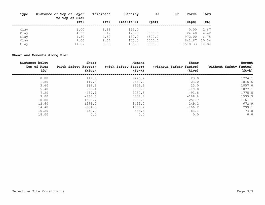
Ultimate Resisting Forces Along Pier
Selective Site Consultants Page 3/3
Type Distance of Top of Layer Thickness Density CU KP Force Arm
to Top of Pier
(ft) (ft) (lbs/ft^3) (psf) (kips) (ft)
--------------------------------------------------------------------------------------------------- Clay 1.00 3.33 125.0 0.00 2.67
Clay 4.33 0.17 125.0 3000.0 24.48 4.42
Clay 4.50 4.50 130.0 4500.0 972.00 6.75
Clay 9.00 2.67 135.0 5000.0 641.67 10.34
Clay 11.67 6.33 135.0 5000.0 -1518.33 14.84
Shear and Moments Along Pier
Distance below Shear Moment Shear Moment
Top of Pier (with Safety Factor) (with Safety Factor) (without Safety Factor) (without Safety Factor)
(ft) (kips) (ft-k) (kips) (ft-k)
------------------------------------------------------------------------------------------------------------------------ 0.00 119.8 9225.2 23.0 1774.1
1.80 119.8 9440.9 23.0 1815.6
3.60 119.8 9656.6 23.0 1857.0
5.40 -99.1 9760.7 -19.0 1877.1
7.20 -487.9 9232.5 -93.8 1775.5
9.00 -876.7 8004.4 -168.6 1539.3
10.80 -1308.7 6037.6 -251.7 1161.1
12.60 -1296.0 3499.2 -249.2 672.9
14.40 -864.0 1555.2 -166.2 299.1
16.20 -432.0 388.8 -83.1 74.8
18.00 0.0 0.0 0.0 0.0

TIA Rev G
Site Data
BU#: 1696 ft-kips
Site Name: 19 kips
App #: 23 kips
Other Eta Factor, η 0.5 TIA G (Fig. 4-4)
If No stiffeners, Criteria: AISC LRFD <-Only Applcable to Unstiffened Cases
Qty: 12
Diam: 2.25 in
Rod Material: A615-J Anchor Rod Results Rigid
Strength (Fu): 100 ksi Max Rod (Cu+ Vu/ή): 164.1 Kips AISC LRFD
Yield (Fy): 75 ksi Allowable Axial, Φ*Fu*Anet: 260.0 Kips φ*Tn
Bolt Circle: 42.74 in Anchor Rod Stress Ratio: 63.1% Pass
Diam: 48.74 in Base Plate Results Flexural Check Rigid
Thick: 2.75 in Base Plate Stress: 21.0 ksi AISC LRFD
Grade: 60 ksi Allowable Plate Stress: 54.0 ksi φ*Fy
Single-Rod B-eff: 9.38 in Base Plate Stress Ratio: 38.9% Pass Y.L. Length:
24.53
n/a
Config: 0 * Stiffener Results
Weld Type: Horizontal Weld : n/a
Groove Depth: in ** Vertical Weld: n/a
Groove Angle: degrees Plate Flex+Shear, fb/Fb+(fv/Fv)^2: n/a
Fillet H. Weld: <-- Disregard Plate Tension+Shear, ft/Ft+(fv/Fv)^2:n/a
Fillet V. Weld: in Plate Comp. (AISC Bracket): n/a
Width: in
Height: in Pole Results
Thick: in Pole Punching Shear Check: n/a
Notch: in
Grade: ksi
Weld str.: ksi
Diam: 35 in
Thick: 0.406 in
Grade: 65 ksi
# of Sides: 12 "0" IF Round
Fu 80 ksi
Reinf. Fillet Weld 0 "0" if None
* 0 = none, 1 = every bolt, 2 = every 2 bolts, 3 = 2 per bolt
** Note: for complete joint penetration groove welds the groove depth must be exactly 1/2 the stiffener thickness for calculation purposes
Stiffener Data (Welding at both sides)
875268
Reactions
Mu:
Axial, Pu:
Shear, Vu:
Dublin Scioto Park
Pole Manufacturer:
Assumption: Clear space between bottom of leveling nut and top of concrete not exceeding (1)*(Rod Diameter)
Stiffened or Unstiffened, Ungrouted, Circular Base Plate - Any Rod Material
206097 Rev #2
Pole Data
Anchor Rod Data
Plate Data
CCIplate 1.5 - Circular Base G 1.3, Effective March 19, 2012 Analysis Date: 12/6/2013

Site Data
BU#: G
Site Name: 1884.8 ft-kips (* Note)
App #: 19 kips
Comp.
For M (WL) 1.3 <----Disregard
For P (DL) 1.3 <----Disregard Load Factor
1.00 Mu: 1884.8 ft-kips
1.00 Pu: 19 kips
Concrete:
6.0 ft
4071.5 in2
4000 psi
60 ksi
Reinforcement: 29000 ksi
8.00 in 0.00207
Horiz. Tie Bar Size= 4 0.003
4.47 ft
53.59 in 2005
11
1.41 in D
1.56 in2
Seismic Risk = High
32
As Total= 49.92 in2
Solve <-- Press Upon Completing All Input
A s/ Aconc, Rho: 0.0123 1.23% (Run)
ACI 10.5 , ACI 21.10.4, and IBC 1810. Results:Min As for Flexural, Tension Controlled, Shafts: Governing Orientation Case: 1
(3)*(Sqrt(f'c)/Fy: 0.0032
200 / Fy: 0.0033
Dist. From Edge to Neutral Axis: 15.99 in
Extreme Steel Strain, єt: 0.0088
Minimum Rho Check:
Actual Req'd Min. Rho: 0.33% Flexural Reduction Factor,φ: 0.900Provided Rho: 1.23% OK
Ref. Shaft Max Axial Capacities, φ Max(Pn or Tn):
Output Note: Negative Pu=Tension
8667.66 kips For Axial Compression, φ Pn = Pu: 19.00 kips
4234.40 ft-kips Drilled Shaft Moment Capacity, φMn: 5875.78 ft-kips
Drilled Shaft Superimposed Mu: 1884.80 ft-kips
2695.68 kips
0.00 ft-kips 32.1%
ACI 318 Code
Select Analysis ACI Code=
Note: Shaft assumed to have ties, not spiral, transverse reinforcing
Reinforcing Modulus of Elasticity, E =
Reinforcement yield strain =
875268
Dublin Scioto Park
206097 Rev #2
(*) Note: Max Shaft Superimposed Moment does not necessarily
equal to the shaft top reaction moment
Clear Cover to Tie=
Moment Capacity of Drilled Concrete Shaft (Caisson) for TIA Rev F or G
TIA Revision:
Max. Factored Shaft Mu:
Max. Factored Shaft Pu:
Maximum Shaft Superimposed Forces
Max Axial Force Type:
Seismic Design Category =
Vert. Cage Diameter =
Loads Already Factored
Shaft Factored Loads
Bar Area =
Pier Properties
Pier Diameter =
Concrete Comp. strength, f'c =
Reinforcement yield strength, Fy =
Concrete Area =
Max Tu, (φ=0.9) Tn =
at Mu=φ=(0.90)Mn=
at Mu=(φ=0.65)Mn=
Max Pu = (φ=0.65) Pn.
Pn per ACI 318 (10-2)
(Mu/φMn, Drilled Shaft Flexure CSR:
єt > 0.0050, Tension Controlled
Case 1 Case 2
Limiting compressive strain =
Vertical Bar Size = Seismic Properties
Bar Diameter =
Material Properties
Number of Bars =
Vert. Cage Diameter =
Mu Mu
EQ EQ
Drilled_Shaft_Moment_Capacity, DSMC, Version 1.1 - Effective 04/01/ 2010 Analysis Date: 12/6/2013

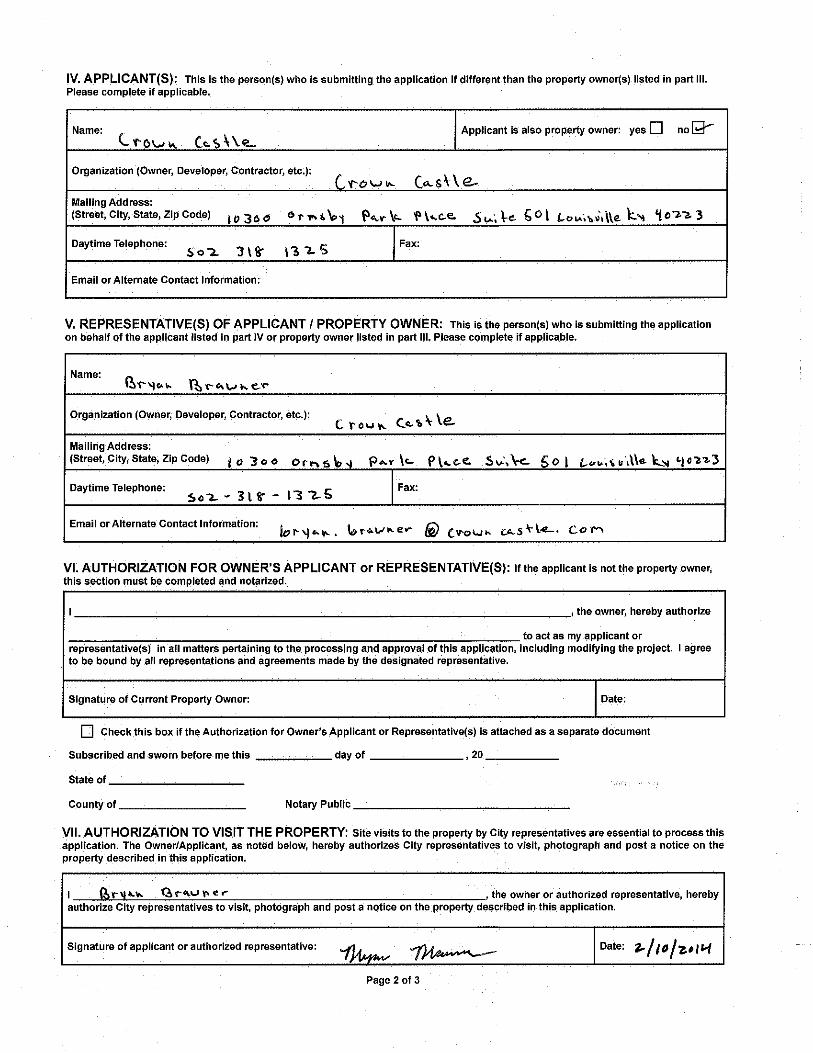


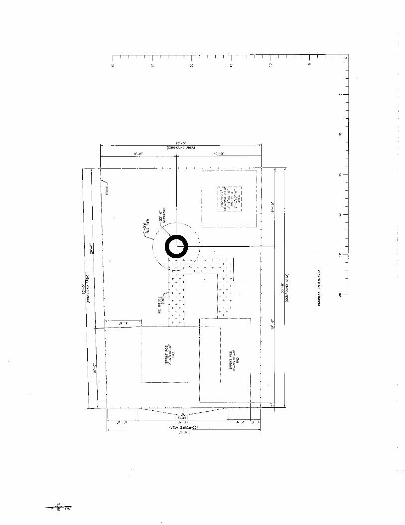

![The OpenCV Tutorials · •ffmpeg or libav development packages: libavcodec-dev, libavformat-dev, libswscale-dev; •[optional] libdc1394 2.x; •[optional] libjpeg-dev, libpng-dev,](https://static.fdocuments.us/doc/165x107/6053a6970cae8c6eef1624b2/the-opencv-affmpeg-or-libav-development-packages-libavcodec-dev-libavformat-dev.jpg)