7300 Operator Manual - Tennant Co · 7300 *330610* Rider Scrubber Operator Manual 330610 Rev. 19...
128
7300 *330610* Rider Scrubber Operator Manual 330610 Rev. 19 (6-2014) The Safe Scrubbing Alternative R ES R Extended Scrub System Tennant True R Parts IRIS R a Tennant Technology (Battery) North America / International R For latest parts manual or other Operator language manual, visit: www.tennantco.com/manuals
-
Upload
nguyenkiet -
Category
Documents
-
view
224 -
download
0
Transcript of 7300 Operator Manual - Tennant Co · 7300 *330610* Rider Scrubber Operator Manual 330610 Rev. 19...

7300
*330610*
Rider ScrubberOperator Manual
330610Rev. 19 (6-2014)
The Safe Scrubbing Alternative�
ES� Extended Scrub SystemTennantTrue� Parts
IRIS� a Tennant Technology
(Battery)
North America / International
�
For latest parts manual or otherOperator language manual, visit:
www.tennantco.com/manuals

This manual is furnished with each new model. It provides necessary operation and maintenance instructions.
Read this manual completely and understand the machine before operating or servicing it.
This machine will provide excellent service. However, the best results will be obtained at minimum costs if:
� The machine is operated with reasonable care.
� The machine is maintained regularly - per the machine maintenance instructions provided.
� The machine is maintained with manufacturer supplied or equivalent parts.
PROTECT THE ENVIRONMENTPlease dispose of packaging materials,old machine components such asbatteries, hazardous fluids such asantifreeze and oil, in an environmentallysafe way according to local wastedisposal regulations.
Always remember to recycle.
MACHINE DATA
Please fill out at time of installation for future reference.
Model No. −
Serial No. −
Machine Options −
Sales Rep. −
Sales Rep. phone no. −
Customer Number −
Installation Date −
Tennant CompanyPO Box 1452Minneapolis, MN 55440Phone: (800) 553−8033 or (763) 513−2850www.tennantco.com
Thermo−Sentry, SmartRelease, SuperScrub, and MaxPro are US registered and unregistered trademarks of Tennant Company.
Specifications and parts are subject to change without notice.
Copyright � 2000 − 2002, 2004 − 2014 TENNANT Company, Printed in U.S.A.

CONTENTS
17300 330610 (6−09)
CONTENTS
PageSafety Precautions 3. . . . . . . . . . . . . . . . . . . . . . .Operation 5. . . . . . . . . . . . . . . . . . . . . . . . . . . . . . .
Operator Responsibility 5. . . . . . . . . . . . . . . . .Machine Components 6. . . . . . . . . . . . . . . . . .Symbol Definitions 7. . . . . . . . . . . . . . . . . . . . .Symbol Definitions 8. . . . . . . . . . . . . . . . . . . . .Controls And Instruments 9. . . . . . . . . . . . . . .Operation Of Controls 10. . . . . . . . . . . . . . . . . .
Brake Pedal 10. . . . . . . . . . . . . . . . . . . . . . .Parking Brake Pedal 10. . . . . . . . . . . . . . . .Directional Pedal 10. . . . . . . . . . . . . . . . . . .Steering Wheel 11. . . . . . . . . . . . . . . . . . . . .On-off Key Switch 12. . . . . . . . . . . . . . . . . .Horn Button 12. . . . . . . . . . . . . . . . . . . . . . . .Power Kill Switch 13. . . . . . . . . . . . . . . . . . .Operating Lights Switch 13. . . . . . . . . . . . .Power Wand Switch (Option) 13. . . . . . . . .Solution Flow Lever 14. . . . . . . . . . . . . . . . .Steering Column Tilt Lever 14. . . . . . . . . . .FaST Switch 14. . . . . . . . . . . . . . . . . . . . . . .ec−H20 Switch 15. . . . . . . . . . . . . . . . . . . . .Control Panel 15. . . . . . . . . . . . . . . . . . . . . .Changing Display Language 16. . . . . . . . .Battery Discharge Indicator 17. . . . . . . . . .Hourmeter 17. . . . . . . . . . . . . . . . . . . . . . . . .Display Clock 18. . . . . . . . . . . . . . . . . . . . . .Setting The Display Clock 18. . . . . . . . . . . .Scrub Switch 19. . . . . . . . . . . . . . . . . . . . . . .Super Scrub Switch (For machines without Optional Side Brush) 20. . . . . . . . .Super Scrub Switch (For machines with Optional Side Brush) 20. . . . . . . . . . . .Recovery Tank Full Indicator 21. . . . . . . . .ES Switch (Option) 21. . . . . . . . . . . . . . . . .Edge Scrub Switch 21. . . . . . . . . . . . . . . . .Rear Squeegee Switch 22. . . . . . . . . . . . . .Side Brush Switch (Option) 23. . . . . . . . . .Detergent Pump Switch (Option) 24. . . . . .Maintenance Mode 24. . . . . . . . . . . . . . . . .Resetting The Maintenance Timers 25. . .Disabling The Maintenance Mode 26. . . . .Fuses 27. . . . . . . . . . . . . . . . . . . . . . . . . . . . .Circuit Breakers 28. . . . . . . . . . . . . . . . . . . .Solution Tank Drain Hose (Option) 30. . . .Recovery Tank Drain Hose 30. . . . . . . . . . .Positive Solution Control Drain
(Option) 30. . . . . . . . . . . . . . . . . . . . . . . .Latches 30. . . . . . . . . . . . . . . . . . . . . . . . . . .Operator Seat 31. . . . . . . . . . . . . . . . . . . . . .Deluxe Suspension Seat (Option) 31. . . . .Side Brush Adjustment Knob (Option) 32.
How The Machine Works 33. . . . . . . . . . . . . . .FaST Scrubbing System 34. . . . . . . . . . . . . . . .ec−H2O System (Option) 35. . . . . . . . . . . . . . .
PagePre-operation Checklist 36. . . . . . . . . . . . . . . . .Installing FaST PAK Agent 37. . . . . . . . . . . . . .Starting The Machine 39. . . . . . . . . . . . . . . . . .Filling The Tanks 40. . . . . . . . . . . . . . . . . . . . . .Sweeping, Scrubbing And Brush
Information 43. . . . . . . . . . . . . . . . . . . . . . . .Scrubbing 45. . . . . . . . . . . . . . . . . . . . . . . . . .Double Scrubbing 50. . . . . . . . . . . . . . . . . . . . .Stop Scrubbing 50. . . . . . . . . . . . . . . . . . . . . . . .Draining And Cleaning The Tanks 51. . . . . . . .Stop The Machine 56. . . . . . . . . . . . . . . . . . . . .Post-operation Checklist 57. . . . . . . . . . . . . . . .Operation On Inclines 58. . . . . . . . . . . . . . . . . .Options 58. . . . . . . . . . . . . . . . . . . . . . . . . . . . . .
Vacuum Wand 58. . . . . . . . . . . . . . . . . . . . .Power Wand 62. . . . . . . . . . . . . . . . . . . . . . .
Machine Troubleshooting 68. . . . . . . . . . . . . . .Maintenance 70. . . . . . . . . . . . . . . . . . . . . . . . . . . . .
Maintenance Chart 70. . . . . . . . . . . . . . . . . . . .Lubrication 72. . . . . . . . . . . . . . . . . . . . . . . . . . .
Propelling Gearbox 72. . . . . . . . . . . . . . . . .Front Wheel Support Bearing 72. . . . . . . . .Scrub Head Drag Link Arms
(S/N 000000−003695) 73. . . . . . . . . . . .Rear Wheel Bearings 74. . . . . . . . . . . . . . .Steering Gear Chain 74. . . . . . . . . . . . . . . .
Hydraulics (Option) 75. . . . . . . . . . . . . . . . . . . .Hydraulic Fluid Reservoir 75. . . . . . . . . . . .Hydraulic Fluid 76. . . . . . . . . . . . . . . . . . . . .Hydraulic Hoses 76. . . . . . . . . . . . . . . . . . . .
Batteries 77. . . . . . . . . . . . . . . . . . . . . . . . . . . . .Charging The Batteries 78. . . . . . . . . . . . . .
Control Panel 80. . . . . . . . . . . . . . . . . . . . . . . . .Electric Motors 82. . . . . . . . . . . . . . . . . . . . . . . .Propelling Circuit 82. . . . . . . . . . . . . . . . . . . . . .Scrub Head 83. . . . . . . . . . . . . . . . . . . . . . . . . . .
Scrub Head Gas Spring 83. . . . . . . . . . . . .Scrub Head Adjustments 83. . . . . . . . . . . .
Scrub Brushes 84. . . . . . . . . . . . . . . . . . . . . . . .Disk Brushes 84. . . . . . . . . . . . . . . . . . . . . . .Replacing The Disk Brushes 84. . . . . . . . .Cylindrical Brushes 87. . . . . . . . . . . . . . . . .
Checking And Adjusting Cylindrical Brush Pattern 87. . . . . . . . . . . . . . . .
Replacing The Cylindrical Brushes 90.Side Sweeping Brush (Option) 92. . . . . . . . . .
Replacing And Adjusting The Side Sweeping Brush(Es) 92. . . . . . . . . . . . .
Solution System 93. . . . . . . . . . . . . . . . . . . . . . .Solution Valve 93. . . . . . . . . . . . . . . . . . . . . .Recovery Tank 93. . . . . . . . . . . . . . . . . . . . .Solution Tank 94. . . . . . . . . . . . . . . . . . . . . .
CONTENTS
7300 330610 (6−09)2
PageFaST System 95. . . . . . . . . . . . . . . . . . . . . . . . .
FaST Supply Hose Connector 95. . . . . . . .FaST System Filter Screen 95. . . . . . . . . .FaST System Air Pump Filter
(S/N 000000−003746) 95. . . . . . . . . . . .FaST System Air Pump Filter
(S/N 003747− ) 96. . . . . . . . . . . . .ec−H2O Module Flush Procedure 97. . . . . . . .Squeegees 99. . . . . . . . . . . . . . . . . . . . . . . . . .
Rear Squeegee 99. . . . . . . . . . . . . . . . . . . .Leveling The Rear Squeegee 99. . . . . .Adjusting Rear Squeegee Blade
Deflection 100. . . . . . . . . . . . . . . . . . .Removing The Rear Squeegee
Assembly 101. . . . . . . . . . . . . . . . . . .Side Squeegee 102. . . . . . . . . . . . . . . . . . . .
Adjusting The Side Squeegee 102. . . .Squeegee Blades 102. . . . . . . . . . . . . . . . . . . . .
Rear Squeegee Blades 102. . . . . . . . . . . . .Replacing Or Rotating The Rear
Squeegee Blades 102. . . . . . . . . . . .Side Squeegees Blades 104. . . . . . . . . . . .
Replacing The Side Squeegee Blades 104. . . . . . . . . . . . . . . . . . . . . .
Belts And Chains 105. . . . . . . . . . . . . . . . . . . . .Brush Drive Belts 105. . . . . . . . . . . . . . . . . .Steering Gear Chain 105. . . . . . . . . . . . . . .Static Drag Chain 105. . . . . . . . . . . . . . . . . .
Skirts And Seals 106. . . . . . . . . . . . . . . . . . . . . .Scrub Head Floor Skirts 106. . . . . . . . . . . .Front Cover Seals 106. . . . . . . . . . . . . . . . .Solution Tank Cover Seal 107. . . . . . . . . . .Recovery Tank Cover Seal 107. . . . . . . . . .
Brakes And Tires 108. . . . . . . . . . . . . . . . . . . . .Brakes 108. . . . . . . . . . . . . . . . . . . . . . . . .Tires 108. . . . . . . . . . . . . . . . . . . . . . . . . . . .Front Wheel 108. . . . . . . . . . . . . . . . . . . . . .
Pushing, Towing, And Transporting The Machine 109. . . . . . . . . . . . . . . . . . . . . . . . .Pushing Or Towing The Machine 109. . . . .Transporting The Machine 109. . . . . . . . . .
Machine Jacking 111. . . . . . . . . . . . . . . . . . . . .Storage Information 112. . . . . . . . . . . . . . . . . . .
Freeze Protection (Machines Without Optional ec−H2O System) 112. . . . . . .
Freeze Protecting The ec−H2O System 113. . . . . . . . . . . . . . . .
Flushing Antifreeze From The ec−H2O Module 115. . . . . . . . . . . . . . . .
PageSpecifications 116. . . . . . . . . . . . . . . . . . . . . . . . . . .
General Machine Dimensions/Capacities 116Fast System 116. . . . . . . . . . . . . . . . . . . . . . . . .General Machine Performance 116. . . . . . . . .Power Type 117. . . . . . . . . . . . . . . . . . . . . . . . . .Steering 118. . . . . . . . . . . . . . . . . . . . . . . . . . . . .Hydraulic System 118. . . . . . . . . . . . . . . . . . . . .Braking System 118. . . . . . . . . . . . . . . . . . . . . .Tires 118. . . . . . . . . . . . . . . . . . . . . . . . . . . . . . . .ec−H2O System 118. . . . . . . . . . . . . . . . . . . . . .Machine Dimensions 119. . . . . . . . . . . . . . . . . .
Index 120. . . . . . . . . . . . . . . . . . . . . . . . . . . . . . . . . .

SAFETY PRECAUTIONS
37300 330610 (7−2012)
SAFETY PRECAUTIONS
The following symbols are used throughout thismanual as indicated in their description:
WARNING: To warn of hazards orunsafe practices that could result insevere personal injury or death.
FOR SAFETY: To identify actions thatmust be followed for safe operation ofequipment.
The following information signals potentiallydangerous conditions to the operator orequipment. Read this manual carefully. Knowwhen these conditions can exist. Locate all safetydevices on the machine. Then, take necessarysteps to train machine operating personnel.Report machine damage or faulty operationimmediately. Do not use the machine if it is not inproper operating condition.
WARNING: Batteries emit hydrogen gas.Explosion or fire can result. Keepsparks and open flame away. Keepcovers open when charging.
WARNING: Flammable materials cancause an explosion or fire. Do not useflammable materials in tank(s).
WARNING: Flammable materials orreactive metals can cause explosion orfire. Do not pick up.
FOR SAFETY:
This machine may be equiped withtechnology that automatically communicatesover the cellular network. If this machine willbe operated where cell phone use is restrictedbecause of concerns related to equipmentinterference, please contact a Tennantrepresentative for information on how todisable the cellular communicationfunctionality.
1. Do not operate machine:− Unless trained and authorized.− Unless operation manual is read and
understood.− Unless mentally and physically
capable of following machineinstructions.
− In flammable or explosive areas unlessdesigned for use in those areas.
− In areas with possible falling objectsunless equipped with overhead guard.
2. Before starting machine:− Make sure all safety devices are in
place and operate properly.− Check brakes and steering for proper
operation.
3. When starting machine:− Keep foot on brake and directional
pedal in neutral.
4. When using machine:− Use brakes to stop machine.− Go slow on inclines and slippery
surfaces.− Use care when backing machine.− Do not carry riders on machine.− Follow mixing and handling
instructions on chemical containers.− Always follow safety and traffic rules.− Report machine damage or faulty
operation immediately.− Follow safety guidelines concerning
wet floors.
5. Before leaving or servicing machine:− Stop on level surface.− Set parking brake.− Turn off machine and remove key.
6. When servicing machine:− Avoid moving parts. Do not wear loose
jackets, shirts, or sleeves whenworking on machine.
− Block machine tires before jackingmachine up.
− Jack machine up at designatedlocations only. Block machine up withjack stands.
− Use hoist or jack that will support theweight of the machine.
− Wear eye and ear protection whenusing pressurized air or water.
− Disconnect battery connections beforeworking on machine.
− Wear protective gloves and eyeprotection when handling vinegar.
− Avoid contact with battery acid.− Use Tennant supplied or equivalent
replacement parts.

SAFETY PRECAUTIONS
7300 330610 (NIL)4
7. When loading/unloading machineonto/off truck or trailer:− Turn off machine.− Use truck or trailer that will support
the weight of the machine.− Use winch. Do not drive the machine
onto/off the truck or trailer unless theload height is 380 mm (15 in) or lessfrom the ground.
− Set parking brake after machine isloaded.
− Block machine tires.− Tie machine down to truck or trailer.

SAFETY PRECAUTIONS
57300 330610 (10−09)
The safety labels appear on the machine in thelocations indicated. If these or any label becomesdamaged or illegible, install a new label in itsplace.
BATTERYCHARGING LABEL −LOCATED ON THELINTEL.
FOR SAFETY LABEL −LOCATED ON THE INSIDEOF THE OPERATORCOMPARTMENT.
FLAMMABLE SPILLS LABEL −LOCATED ON THE INSIDE OF THEOPERATOR COMPARTMENT.
FLAMMABLE MATERIALSLABEL − LOCATED ON THEINSIDE OF THE SOLUTIONTANK COVER.
353374

OPERATION
7300 330610 (6−00)6
OPERATION
OPERATOR RESPONSIBILITY
� The operator’s responsibility is to take careof the daily maintenance and checkups ofthe machine to keep it in good workingcondition. The operator must inform theservice mechanic or supervisor when themaintenance intervals are required as statedin the MAINTENANCE section of thismanual.
� Read this manual carefully before operatingthis machine.
FOR SAFETY: Do not operate machine,unless operation manual is read andunderstood.
� Check the machine for shipping damage.Check to make sure the machine iscomplete per shipping instructions.
� Keep your machine regularly maintained byfollowing the maintenance information in thismanual. We recommend taking advantageof a regularly scheduled service contractfrom your Tennant representative.
� Order parts and supplies directly from yourauthorized Tennant representative. Use theparts manual provided when ordering parts.
� After the first 50 hours of operation, followthe recommended procedures stated in theMAINTENANCE CHART.
07324

OPERATION
77300 330610 (6−09)
MACHINE COMPONENTS
B
C
D
J F
D
C
E
G
GH
I
J
A
E
K
L
L
A. Operator seatB. Steering wheelC. Machine coverD. Recovery tankE. Solution tankF. Rear squeegeeG. Side squeegeeH. Solution tank drainI. Recovery tank drainJ. Rear wheelK. Side Brush (Option)L. FaST solution system
ec−H2O System Module (Option)

OPERATION
7300 330610 (12−01)8
SYMBOL DEFINITIONS
These symbols identify controls, displays, andfeatures on the machine:
Battery charging system Solution tank full
Hourmeter Solution tank low
Recovery tank full Variable pressure
ES (option) Steering tilt
Scrub switch Circuit breaker #1
Scrub brush up and off Circuit breaker #2
Scrub brush down pressure Circuit breaker #3
Super scrub Circuit breaker #4
Scrub brush edge clean Circuit breaker #5
Squeegee up Circuit breaker #6
Squeegee down Circuit breaker #7
Key switch Circuit breaker #8
Operating lights Circuit breaker #9
Hazard light (option) Circuit breaker #10

OPERATION
97300 330610 (6−09)
SYMBOL DEFINITIONS
Horn Circuit breaker #11
50 hour required maintenance interval Circuit breaker #12
100 hour required maintenance interval Circuit breaker #13
500 hour required maintenance interval Circuit breaker #14
1000 hour required maintenance interval Circuit breaker #15
Detergent flow on (option) Circuit breaker #16
Detergent flow heavy (option) Circuit breaker #17
Detergent flow off (option) Circuit breaker #18
Side brush down and on (option) Diagnostics
Side Brush up and off (option) Power Wand (option)
ec−H20 (option) Jackpoint

OPERATION
7300 330610 (6−09)10
CONTROLS AND INSTRUMENTS
A B
D
C
H
I
K
F
E
G
J
L
M
N
OP
Q
R
A. Steering wheelB. Horn buttonC. Operating lights switchD. Power kill switchE. Power wand switch (option)F. On/Off key switchG. Steering column tilt leverH. Parking brake pedalI. Brake pedalJ. Directional pedalK. Operator seatL. Solution flow leverM. Display screenN. Multi−function switches (6)O. TENNANT logo switchP. Control panelQ. FaST switch
ec−H2O system on/off switch (option)R. ec−H2O system indicator light (option)

OPERATION
117300 330610 (6−09)
OPERATION OF CONTROLS
BRAKE PEDAL
The brake pedal stops the machine.
Stop: Take your foot off the directional pedal andlet it return to the neutral position. Step on thebrake pedal.
PARKING BRAKE PEDAL
The parking brake pedal sets and releases both ofthe rear wheel brakes.
Set: Press the brake pedal down as far aspossible, then press on the parking brake pedalwith the toe of your foot to lock the parking brakepedal in place.
FOR SAFETY: Before leaving orservicing machine, stop on levelsurface, set parking brake, turn offmachine, and remove key.
Release: Press down on the brake pedal until theparking brake releases.
DIRECTIONAL PEDAL
The directional pedal controls direction of traveland the propelling speed of the machine. Youchange the speed of the machine with thepressure of your foot; the harder you press thefaster the machine travels.
When the machine is moving forward and thedirectional pedal is reversed, the machine willcoast for a short distance before changingdirection. Use the brake pedal to stop themachine.
Forward: Press the top of the directional pedalwith the toe of your foot.

OPERATION
7300 330610 (6−09)12
Reverse: Press the bottom of the directionalpedal with the heel of your foot.
Neutral: Take your foot off the directional pedaland it will return to the neutral position.
STEERING WHEEL
The steering wheel controls the machine’sdirection. The machine is very responsive to thesteering wheel movements.
Left: Turn the steering wheel to the left.
Right: Turn the steering wheel to the right.
OPERATION
137300 330610 (6−00)
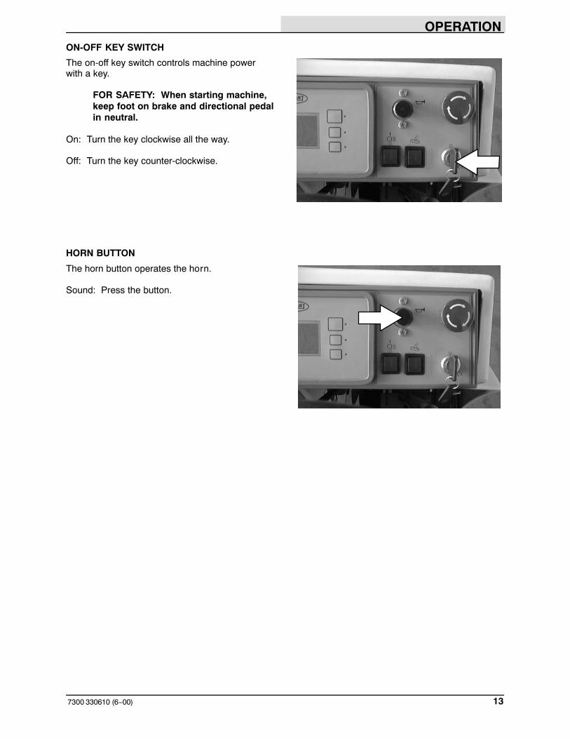
ON-OFF KEY SWITCH
The on-off key switch controls machine powerwith a key.
FOR SAFETY: When starting machine,keep foot on brake and directional pedalin neutral.
On: Turn the key clockwise all the way.
Off: Turn the key counter-clockwise.
HORN BUTTON
The horn button operates the horn.
Sound: Press the button.

OPERATION
7300 330610 (6−00)14
POWER KILL SWITCH
The power kill switch halts all power to themachine.
FOR SAFETY: When starting machine,keep foot on brake and directional pedalin neutral.
Halt: Push the power kill switch in.
Restart: Turn off the machine with the on/offswitch. Turn the power kill switch to the right torelease the switch. Turn on the machine with theon/off key switch.
OPERATING LIGHTS SWITCH
The operating lights switch powers on and off theheadlights and taillights.
On: Press the top of the operating lights switch.
Off: Press the bottom of the operating lightsswitch.
POWER WAND SWITCH (OPTION)
The power wand switch turns on and off thepower wand solution system option.
On: Press the top of the switch.
Off: Press the bottom of the switch.
OPERATION
157300 330610 (6−09)
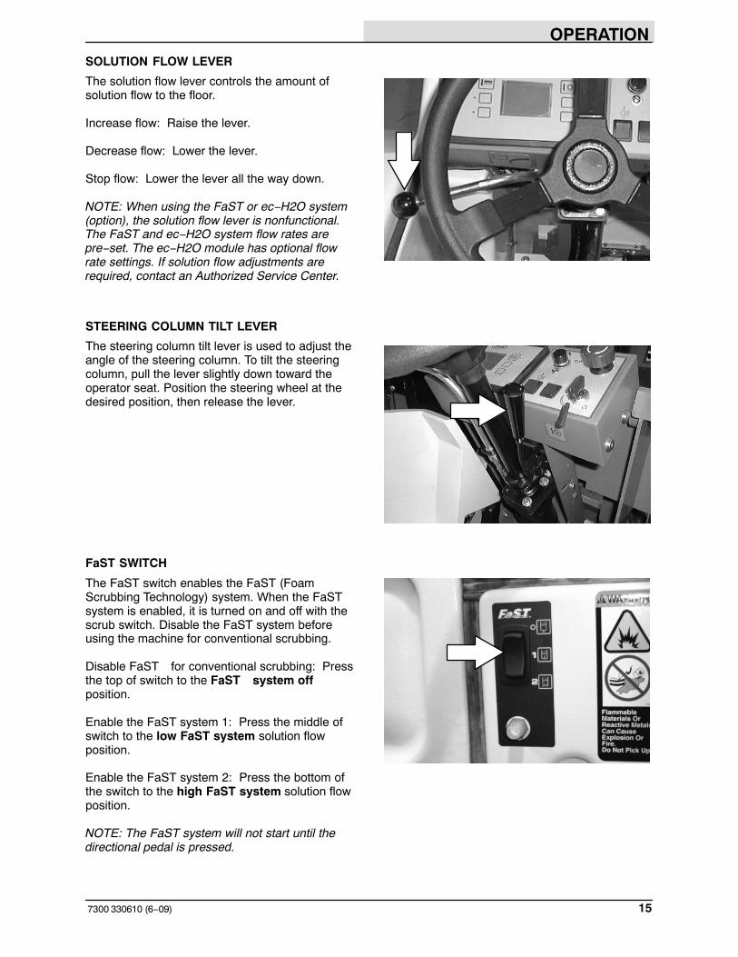
SOLUTION FLOW LEVER
The solution flow lever controls the amount ofsolution flow to the floor.
Increase flow: Raise the lever.
Decrease flow: Lower the lever.
Stop flow: Lower the lever all the way down.
NOTE: When using the FaST or ec−H2O system(option), the solution flow lever is nonfunctional.The FaST and ec−H2O system flow rates arepre−set. The ec−H2O module has optional flowrate settings. If solution flow adjustments arerequired, contact an Authorized Service Center.
STEERING COLUMN TILT LEVER
The steering column tilt lever is used to adjust theangle of the steering column. To tilt the steeringcolumn, pull the lever slightly down toward theoperator seat. Position the steering wheel at thedesired position, then release the lever.
FaST SWITCH
The FaST switch enables the FaST (FoamScrubbing Technology) system. When the FaSTsystem is enabled, it is turned on and off with thescrub switch. Disable the FaST system beforeusing the machine for conventional scrubbing.
Disable FaST for conventional scrubbing: Pressthe top of switch to the FaST system offposition.
Enable the FaST system 1: Press the middle ofswitch to the low FaST system solution flowposition.
Enable the FaST system 2: Press the bottom ofthe switch to the high FaST system solution flowposition.
NOTE: The FaST system will not start until thedirectional pedal is pressed.

OPERATION
7300 330610 (6−09)16
ec−H2O SWITCH (OPTION)
The ec−H2O switch (option) enables the ec−H2O(Electrically activated water) system. When theec−H2O system is enabled, it is turned on and offwith the scrub switch.
ec−H2O low setting: Press the top of the ec−H2Oswitch.
ec−H2O high setting: Place the ec−H2O switchinto the middle position.
Conventional scrubbing: Press the bottom of theec−H2O switch.
NOTE: The ec−H2O system will not start until themachine starts scrubbing.
NOTE: Do not enable the ec−H2O system withconventional cleaning detergents in the solutiontank. Drain, raise and refill the solution tank withclear cool water only before operating the ec−H2Osystem. Conventional cleaning detergents/restorers may cause failure to the ec−H2Osolution system.
CONTROL PANEL
The scrubbing and optional sweeping functionsare activated by the control panel. Features of thecontrol panel include six multi−function buttonsand graphics icons which display the current stateof the scrubbing and optional sweeping functions.The control panel also features a display clock foroperator convenience, and a maintenance modethat prompts the operator when to perform routinemachine maintenance.
By pressing the TENNANT logo switch, theoperator can cycle the control panel displaythrough the different function screens. Eachfunction screen allows the operator to enable ordisable different scrubbing functions.
0020
12 : 16 PM
353550

OPERATION
177300 330610 (12−00)
CHANGING DISPLAY LANGUAGE
1. Turn the machine power off.
2. Press and hold the logo switch.
3. Turn the machine power on.
4. Continue pressing the logo switch for 15seconds or until the down pressure displayscreen appears.
5. Press and release the logo switch 3 times toscroll to the language select mode.
6. Press the first switch on the control panel toscroll through the list of languages until thedesired language is displayed.
7. Turn the machine power off, and the newlanguage will be stored in the control panel.
353556
ENGLISH
Restrict Press.
Enable sweep
353555
OPERATION
7300 330610 (12−00)18
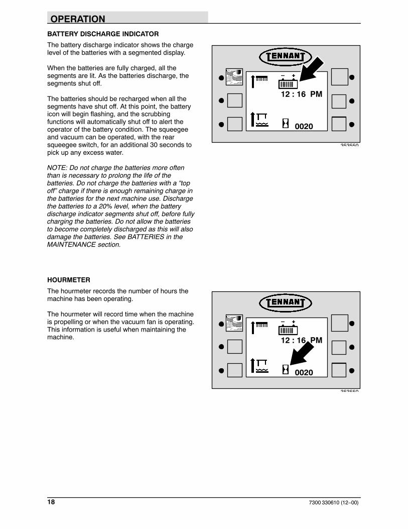
BATTERY DISCHARGE INDICATOR
The battery discharge indicator shows the chargelevel of the batteries with a segmented display.
When the batteries are fully charged, all thesegments are lit. As the batteries discharge, thesegments shut off.
The batteries should be recharged when all thesegments have shut off. At this point, the batteryicon will begin flashing, and the scrubbingfunctions will automatically shut off to alert theoperator of the battery condition. The squeegeeand vacuum can be operated, with the rearsqueegee switch, for an additional 30 seconds topick up any excess water.
NOTE: Do not charge the batteries more oftenthan is necessary to prolong the life of thebatteries. Do not charge the batteries with a “topoff” charge if there is enough remaining charge inthe batteries for the next machine use. Dischargethe batteries to a 20% level, when the batterydischarge indicator segments shut off, before fullycharging the batteries. Do not allow the batteriesto become completely discharged as this will alsodamage the batteries. See BATTERIES in theMAINTENANCE section.
HOURMETER
The hourmeter records the number of hours themachine has been operating.
The hourmeter will record time when the machineis propelling or when the vacuum fan is operating.This information is useful when maintaining themachine.
0020
12 : 16 PM
353550
0020
12 : 16 PM
353550

OPERATION
197300 330610 (12−00)
DISPLAY CLOCK
The display clock shows the time of day below thebattery discharge indicator.
SETTING THE DISPLAY CLOCK
1. Turn the machine off.
2. Press and hold the logo switch.
3. Turn the machine power on.
4. Continue pressing the logo switch for 15seconds or until the down pressure displayscreen appears.
5. Press and release the logo switch one time to scroll to the adjust time mode.
6. Press the switch next to ADJUST TIME.
7. Set the time, date, and choose between the12 or 24 hour clock modes by moving theunderline through the display by pressingthe switches next to the direction arrows.Increase the value of the underlinedsegment by pressing the switch next to thepositive (+) icon. Decrease the value of theunderlined segment by pressing the switchnext to the negative (−) icon.
8. Exit the ADJUST TIME function by pressingthe TENNANT logo switch.
9. Turn the key to the off position.
0020
12 : 16 PM
353550
Input Display
Adjust Time
Enable Edge
353553
353557
+_12
12 : 00 AM−01 / 01 / 97

OPERATION
7300 330610 (6−09)20
SCRUB SWITCH
The scrub switch controls the scrubbing andoptional sweeping operations. The scrub switchalso sets the scrub brush pressure.
The scrubbing operations include the following:The scrub head lowers and the scrub brushesturn on. The rear squeegee will lower and thevacuum fan will start. The optional sweeping sidebrush(es) lowers and the sweeping brushes turnon. The solution system will start, if the solutionflow lever is on. The optional FaST, ec−H20, orES system and detergent pump will start, if theswitches are on.
Start scrubbing: Press the scrub switch. Theindicator light next to the switch will illuminate.The scrubbing system will start when the machinemoves forward.
NOTE: The brush pressure setting, the FaST /ec−H20 system, the detergent flow rate, the edgescrub, and the ES system will default to the lastsetting used when the scrubbing operations arestarted again.
Stop scrubbing: Press the scrub switch. Theindicator light next to the switch will go off. Firstthe scrub brushes will stop and raise, then therear squeegee will raise and the vacuum will shutoff.
Scrub brush pressure: Press and hold the scrubswitch. The brush pressure will scroll throughthree settings indicated by the small arrows abovethe brush icon. Each arrow indicates a heavierbrush pressure setting.
There is also a fourth brush pressure settingindicated by one large arrow above the brush iconand for machines without the optional side brush,a large arrow will appear in the upper right handcorner of the display screen. It is the heaviestbrush pressure setting, and it is called SuperScrub. It is activated for 30 seconds by pressingthe scrub switch twice quickly, or by pressing theSuper Scrub switch once. See the SUPERSCRUB SWITCH section of the manual.
The pressure setting selected when the scrubswitch is released will be the new default brushpressure setting.
353562
353567
353563

OPERATION
217300 330610 (6−09)
Under normal conditions, the brush pressureshould be set in the minimum settings (one or twodownward arrows). Under heavy grime conditions,the brush pressure should be set in the maximumsettings (three downward arrows or one largearrow). Travel speed and floor conditions willaffect the scrubbing performance.
NOTE: The rear squeegee will raise and thevacuum will shut off when the machine travels inreverse. The squeegee will lower and the vacuumstarts again when the machine travels forward.
NOTE: The scrub brushes will stop when themachine is stopped for a short time. The brusheswill start again when the machine travels forward.
NOTE: The scrub switch also controls theFaST/ec−H2O system (option) when theFaST/ec−H2O system is enabled with theFaST/ec−H2O switch.
SUPER SCRUB SWITCH(For machines without Optional Side Brush)
The Super Scrub switch activates the heaviestor fourth scrub brush pressure setting for 30seconds.
On: Press the switch. The indicator light next tothe switch will illuminate.
Off: Press the switch. The indicator light next tothe switch will go off. (Super Scrub willautomatically shut off after 30 seconds)
NOTE: The Super Scrub icon only appears afterthe scrub functions have been activated.
NOTE: The Super Scrub can also be activated bypressing the scrub switch twice quickly.
SUPER SCRUB SWITCH(For machines with Optional Side Brush)
The Scrub Brush switch activates the heaviestor fourth scrub brush pressure setting for 30seconds.
On: Pressing the scrub switch twice quickly. Onelarge arrow above the brush icon will appear.
Off: Press the switch (Super Scrub willautomatically shut off after 30 seconds). The largearrow above the brush icon will disappear.
353562
353562

OPERATION
7300 330610 (9−02)22
RECOVERY TANK FULL INDICATOR
The recovery tank full indicator comes on whenthe recovery tank is full.
If the recovery tank full indicator stays on for morethan 7 seconds, the “Rec. Tank Full” message willappear in the hourmeter display. The scrubbrushes and vacuum will shut off, and the rearsqueegee will raise.
To pick up excess water after the vacuum hasshut off and the rear squeegee has raised, pressand hold the rear squeegee switch.
NOTE: Do not overfill the recovery tank.Overfilling the recovery tank may damage thevacuum fans.
ES SWITCH (OPTION)
The ES (Extended Scrub) switch turns on and offthe solution recycling system. When the scrubbingfunctions have started, the ES will default to thelast setting used.
On: Press the switch. The indicator light next tothe switch will illuminate.
Off: Press the switch. The indicator light next tothe switch will go off.
NOTE: The ES icon only appears after the scrubfunctions have been activated.
NOTE: When using the ES (option), the recoverytank 1/2 full float must be active for the pump tooperate.
EDGE SCRUB SWITCH
The edge scrub switch extends the scrub head tothe right to allow close edge scrubbing. When thescrubbing functions have started, the edge scrubwill default to the last setting used.
NOTE: The edge scrub icon only appears afterthe scrub functions have been activated.
On: Press the switch during normal scrubbing.The indicator light next to the switch willilluminate.
Off: Press the switch again. The indicator lightnext to the switch will go off.
353563
353562
353562
OPERATION
237300 330610 (12−00)
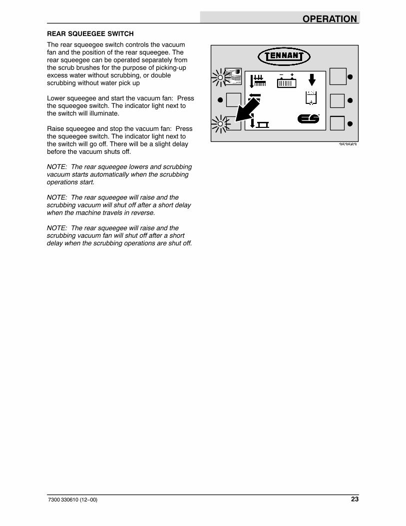
REAR SQUEEGEE SWITCH
The rear squeegee switch controls the vacuumfan and the position of the rear squeegee. Therear squeegee can be operated separately fromthe scrub brushes for the purpose of picking-upexcess water without scrubbing, or doublescrubbing without water pick up
Lower squeegee and start the vacuum fan: Pressthe squeegee switch. The indicator light next tothe switch will illuminate.
Raise squeegee and stop the vacuum fan: Pressthe squeegee switch. The indicator light next tothe switch will go off. There will be a slight delaybefore the vacuum shuts off.
NOTE: The rear squeegee lowers and scrubbingvacuum starts automatically when the scrubbingoperations start.
NOTE: The rear squeegee will raise and thescrubbing vacuum will shut off after a short delaywhen the machine travels in reverse.
NOTE: The rear squeegee will raise and thescrubbing vacuum fan will shut off after a shortdelay when the scrubbing operations are shut off.
353563

OPERATION
7300 330610 (9−02)24
SIDE BRUSH SWITCH (OPTION)
The side brush switch controls the side brushposition and rotation. The scrubbing brush mustbe operating for the side brush to work. Thisoption is available only on cylindrical scrub headmachines.
NOTE: The side brush operates automaticallywhen the scrub brush starts operating. To scrubwithout using the side brush, press the side brushswitch.
Down and On: Press the side brush switch. Theindicator light next to the switch will illuminate,then the side brush will lower and activate.
Up and Off: Press the side brush switch. Theindicator light next to the switch will go out, thenthe side brush will stop and raise.

OPERATION
257300 330610 (6−09)
DETERGENT PUMP SWITCH (OPTION)
The detergent pump switch controls the amount ofdetergent that flows to the floor while scrubbing.When the scrubbing functions have started, thedetergent pump switch will default to the lastsetting used.
NOTE: The detergent icon only appears after thescrub functions have been activated.
NOTE: The detergent pump switch will notactivate unless the main scrub brushes are activeand the solution flow lever is on.
High: Press and hold the detergent pump switchuntil two downward pointing arrows appear on theicon next to the switch. Release the switch. Theindicator light next to the switch will illuminate.
Low: Press and hold the detergent pump switchuntil one downward pointing arrow appears on theicon next to the switch. Release the switch. Theindicator light next to the switch will illuminate.
Off: Press and release the detergent pumpswitch. An ’X’ will appear under the detergentpump icon. The indicator light next to the switchwill go off.
NOTE: When using the ec−H2O system (option),the detergent pump switch is nonfunctional.
MAINTENANCE MODE
The maintenance mode allows the operator tomonitor and reset the elapsed time between thefour different regular maintenance requirements.
When the maintenance mode is enabled, analarm will sound, and one of several servicemaintenance icons will appear on the display eachtime the machine is started. This will happen ifone or more of the maintenance timers goes pastits recommended interval. Each time the requiredmaintenance function is performed, the timer forthat function should be reset.
353551
0020
353558

OPERATION
7300 330610 (12−00)26
RESETTING THE MAINTENANCE TIMERS
1. Turn the machine off.
2. Press and hold the logo switch.
3. Turn the machine power on.
4. Continue pressing the logo switch for 15seconds or until the down pressure displayscreen appears.
5. Press and release the logo switch two moretimes. The SELF TEST screen will appearon the display.
6. Press the switch next to DISPLAY MAINT.
Each maintenance item is represented by anicon with the recommended maintenanceinterval printed in hours below it. The lowerright−hand corner of the screen displays thenumber of hours that have elapsed since themaintenance timer was last reset and thedate it was last reset. The switch at theupper right−hand corner of the screen willreset the hour counter for each maintenanceitem. Reset the maintenance timer eachtime the maintenance function representedby the icon is performed. The operator canscroll through the four maintenance functionscreens by pressing the logo switch.
To determine which routine maintenancefunction each icon represents, see theSYMBOL DEFINITIONS section of thismanual.
0020
12 : 16 PM
353550
Self Test
Display Maint.
Enable Maint.
353560
0020
0
01 / 01 / 97
800
353559

OPERATION
277300 330610 (12−00)
7. Exit the DISPLAY MAINT. function bypressing the logo switch until all fourmaintenance mode screens have beendisplayed.
8. Turn the key to the off position.
DISABLING THE MAINTENANCE MODE
When the maintenance mode is disabled, theflashing icon and alarm will not appear and soundwhen the machine is started if one or more of themaintenance timers goes past its recommendedinterval.
1. Turn the machine off.
2. Press and hold the logo switch.
3. Turn the machine power on.
4. Continue pressing the logo switch for 15seconds or until the down pressure displayscreen appears.
5. Press and release the logo switch two moretimes. The SELF TEST screen will appearon the display.
6. Press the switch next to ENABLE MAINT..
NOTE: If the light next to the ENABLE MAINT.switch is not illuminated, the maintenance mode iscurrently disabled.
NOTE: When the maintenance mode is disabled,the maintenance timers continue to record theelapsed time between maintenance intervals. Toview the elapsed time between each of the sixdefault maintenance intervals, press the switchnext to Display Maint.. Press the logo switch toscroll through the maintenance function screens.
0020
12 : 16 PM
353550
Self Test
Display Maint.
Enable Maint.
353560

OPERATION
7300 330610 (12−02)28
FUSES
The fuses are one-time circuit protection devicesdesigned to stop the flow of current in the event ofa circuit overload. Never substitute higher valuefuses than those specified in this manual.
The main propelling fuse is located under thecircuit breakers in the electrical panel.The two actuator fuses are located in the controlpanel.
Fuse Rating Circuit ProtectedFU 1 150 A Propelling
FU 2 10 A Electronic Actuator
FU 3 10 A Electronic Actuator
OPERATION
297300 330610 (3−11)
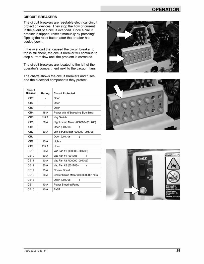
CIRCUIT BREAKERS
The circuit breakers are resetable electrical circuitprotection devices. They stop the flow of currentin the event of a circuit overload. Once a circuitbreaker is tripped, reset it manually by pressing/flipping the reset button after the breaker hascooled down.
If the overload that caused the circuit breaker totrip is still there, the circuit breaker will continue tostop current flow until the problem is corrected.
The circuit breakers are located to the left of theoperator’s compartment next to the vacuum fans.
The charts shows the circuit breakers and fuses,and the electrical components they protect.
CircuitBreaker Rating Circuit Protected
CB1 − Open
CB2 − Open
CB3 − Open
CB4 15 A Power Wand/Sweeping Side Brush
CB5 2.5 A Key Switch
CB6 50 A Right Scrub Motor (000000−001705)
CB6 Open (001706− )
CB7 50 A Left Scrub Motor (000000−001705)
CB7 Open (001706− )
CB8 15 A Lights
CB9 2.5 A Horn
CB10 20 A Vac Fan #1 (000000−001705)
CB10 30 A Vac Fan #1 (001706− )
CB11 20 A Vac Fan #2 (000000−001705)
CB11 30 A Vac Fan #2 (001706− )
CB12 25 A Control Board
CB13 50 A Center Scrub Motor (000000−001705)
CB13 Open (001706− )
CB14 40 A Power Steering Pump
CB15 10 A FaST

OPERATION
7300 330610 (6−09)30
This chart shows the magnetic circuit breakersused on machines serial number 001706 and upfor all cylindrical scrub heads.
CircuitBreaker Rating Circuit Protected
CB6 45 Right Scrub Motor
CB7 45 Left Scrub Motor
CB13 Open
This chart shows the magnetic circuit breakersused on machines serial number 001706 and upwith Max Pro 1000 standard motor disk scrubheads.
CircuitBreaker Rating Circuit Protected
CB6 40 Right Scrub Motor
CB7 40 Left Scrub Motor
CB13 Open
This chart shows the magnetic circuit breakersused on machines serial number 001706 and upwith Max Pro 1000 heavy duty motor diskscrub heads.
CircuitBreaker Rating Circuit Protected
CB6 45 Right Scrub Motor
CB7 45 Left Scrub Motor
CB13 Open
This chart shows the magnetic circuit breakersused on machines serial number 001706 and upwith Max Pro 1200 disk scrub heads.
CircuitBreaker Rating Circuit Protected
CB6 40 Right Scrub Motor
CB7 40 Left Scrub Motor
CB13 40 Center Scrub Motor
This chart shows the magnetic circuit breakersused on machines with an ec−H20 system.
CircuitBreaker Rating Circuit Protected
CB16 2.0 Water Valve
CB17 2.0 ec−H20 Module
CB18 2.0 Solution Pump

OPERATION
317300 330610 (6−00)
SOLUTION TANK DRAIN HOSE (OPTION)
The solution tank drain hose is used to drain thesolution tank after using the ES system. Drain thesolution tank by removing the drain hose cap fromthe tank access cap. Pull out the solution tankhose and remove the drain hose end cap.
RECOVERY TANK DRAIN HOSE
The recovery tank drain hose is used to drain therecovery tank. Drain the recovery tank byremoving the drain hose cap from the tank accesscap. Pull out the recovery tank hose and removethe drain hose end cap.
POSITIVE SOLUTION CONTROL DRAIN(OPTION)
For machines with the positive solution controldrain option, remove the dust cap. Connect thedrain hose to the solution control drain and openthe drain valve by pulling the lever.
LATCHES
The front machine cover is secured with a latch.
Open: Press the raised part of the latch.
Close: Press the flat part of the latch.

OPERATION
7300 330610 (9−02)32
OPERATOR SEAT
The operator set is a fixed back style with aforward-backward adjustment.
Adjust: Pull the lever outward and slide the seatto the desired position, then release the lever.
DELUXE SUSPENSION SEAT (OPTION)
The deluxe suspension seat has fouradjustments. The adjustments are for the lumbarsupport, backrest angle, operator weightadjustment and front to back adjustment.
The lumbar adjustment knob controls the firmnessof the lumbar support.
Increase firmness:Turn knob clockwise.
Decrease firmness:Turn knob counterclockwise.
The back rest angle knob adjusts the angle of theback rest.
Increase angle: Turn the angle adjustment knobcounterclockwise.
Decrease angle: Turn the angle adjustment knobclockwise.
The weight adjustment knob controls the firmnessof the operator’s seat.
Increase firmness: Turn the weight adjustmentknob clockwise.
Decrease firmness: Turn the weight adjustmentknob counterclockwise.
OPERATION
337300 330610 (9−02)
Use the gauge next to the weight adjustment knobto help determine proper seat firmness for theoperator.
The front−to−back adjustment lever adjusts theseat position.
Adjust: Pull the lever out and slide the seatforward or backward to the desired position.Release the lever.
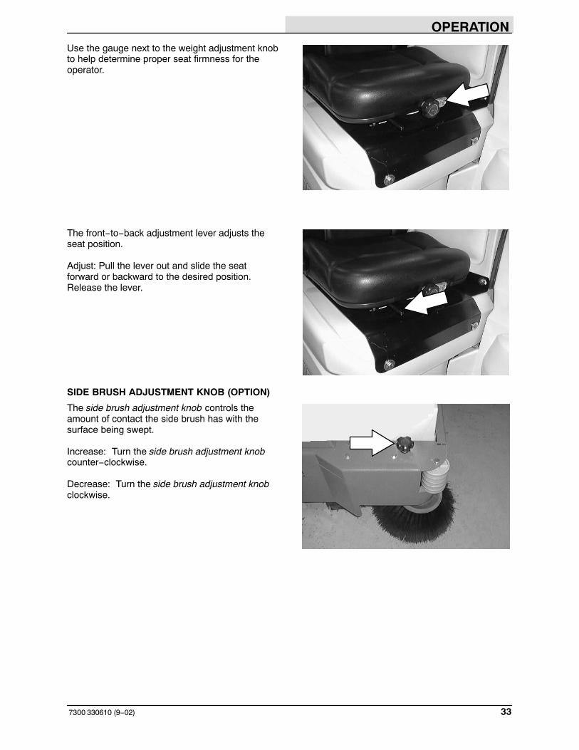
SIDE BRUSH ADJUSTMENT KNOB (OPTION)
The side brush adjustment knob controls theamount of contact the side brush has with thesurface being swept.
Increase: Turn the side brush adjustment knobcounter−clockwise.
Decrease: Turn the side brush adjustment knobclockwise.

OPERATION
7300 330610 (9−02)34
HOW THE MACHINE WORKS
The steering wheel controls the direction ofmachine travel. The directional pedal controls thespeed and forward/reverse directions. The brakepedal slows and stops the machine.
The scrub components of the machine are asolution tank, scrub brushes, rear and sidesqueegees, a vacuum system, and a recoverytank.
Water and detergent, from the solution tank, flowto the floor through a solution valve to the scrubbrushes. The brushes scrub the floor. As themachine is moved forward, the squeegees wipethe dirty solution off the floor, which is then pickedup and drawn into the recovery tank.
The optional side brush(es), available only on thecylindrical scrub head machines, sweep lightdebris into the scrubbing path of the machine. Thescrub brushes sweep the debris into the debristrough.
When using the ES mode (option), the solution inthe recovery tank is filtered and returned to thesolution tank to be reused.
The five available scrub head types use disk orcylindrical brushes.
Two different widths of scrub heads are availablefor each type. The MaxPro 1000 disk scrub head contains twodisk scrub brushes, and is available with standardor heavy duty scrubbing motors. The MaxPro1000 disk scrub head is 1016 mm (40 in).The MaxPro 1200 disk scrub head contains threedisk scrub brushes, and is 1220 mm (48 in).
The MaxPro 1000 cylindrical scrub head is 1016mm (40 in). The MaxPro 1200 cylindrical scrub head is 1220 mm (48 in).
NOTE: The amount and type of soilage play animportant role in determining the type of brushesto be used. For specific recommendations,contact your Tennant representative.
When finished scrubbing, drain and clean therecovery tank. If using the ES system (option),drain and clean the solution tank, and clean theES filter.

OPERATION
357300 330610 (6−09)
FaST SCRUBBING SYSTEM
Unlike conventional scrubbing, the FaST (FoamScrubbing Technology) system operates byinjecting the FaST PAK concentrate agent into thesystem with a small amount of water andcompressed air. This mixture creates a largevolume of expanded wet foam.
The expanded foam mixture is then dispersedonto the floor while the machine is scrubbing.When the squeegee picks up the mixture, thepatented foaming agent has collapsed and isrecovered into the recovery tank.
The FaST system can be used with all doublescrubbing and heavy duty scrubbing applications.
Using the FaST system can increaseproductivity by 30% by reducing your dump/fillcycle. It will also reduce chemical usage andstorage space. One FaST PAK of concentratedagent can scrub up to 1 million sq. ft.
NOTE: Do not use the FaST system withconventional cleaning detergents in the solutiontank. Drain, rinse and refill the solution tank withclear cool water before operating the FaSTsystem. Conventional cleaning detergents andrestorers may cause a FaST system failure.
NOTE: Storing or transporting machines equippedwith the ES or the FaST system in freezingtemperatures requires special procedures.Consult a TENNANT representative for moreinformation.

OPERATION
7300 330610 (6−09)36
ec−H2O SYSTEM (OPTION)
The ec−H2O (electrically converted water) systemoperates by producing electrically converted waterfor cleaning.
Normal water passes through a module where it isoxygenated and charged with an electric current.The electrically converted water changes into ablended acidic and alkaline solution forming aneutral pH cleaner. The converted water attacksthe dirt, breaks it into smaller particles, and pulls itoff the floor surface allowing the machine to easilyscrub away the suspended soil. The convertedwater then returns to normal water in the recoverytank.
The ec−H2O system can be used with all doublescrubbing applications.
NOTE: Do not enable the ec−H2O system withconventional cleaning detergents in the solutiontank. Drain, raise and refill the solution tank withclear cool water only before operating the ec−H2Osystem. Conventional cleaning detergents/restorers may cause failure to the ec−H2Osolution system.
NOTE: Storage or transporting machinesequipped with ec−H2O in freezing temperaturesrequires special procedures. Follow the freezeprotection procedure located in the STORAGEINFORMATION section.

OPERATION
377300 330610 (6−09)
PRE-OPERATION CHECKLIST
Check over this list of items before operating themachine:
� Check the hydraulic fluid level. (if applicable)
� Check the battery fluid and charge level.
� Check the tank cover seals for damage andwear.
� Clean the vacuum fan inlet filter.
� Check the condition of the scrubbingbrushes. Remove any string, banding,plastic wrap, or other debris wrapped around them.
� Check the squeegees for damage, wear andfor deflection adjustment.
� Check the vacuum hose for debris orblockage.
� ES machines; check the detergent tanklevel.
� Drain and clean the recovery tank.
� ES machines; drain and clean the solutiontank and ES filter. Rinse level sensors.
� Check the brakes and steering for properoperation.
� Empty and clean the debris tray. (ifapplicable).
� Check the service records to determinemaintenance requirements.
� FAST Scrubbing: Check the FaST PAKconcentrate agent level, replace carton asneeded. See the INSTALLING THE FaSTPAK AGENT section of the manual.
� For FaST or ec−H2O Scrubbing: Check thatall conventional cleaning agents/restorersare drained and rinsed from the solutiontank.
� For FaST or ec−H2O Scrubbing: Check thatthe solution tank is filled with clear coolwater only.

OPERATION
7300 330610 (6−09)38
INSTALLING FaST PAK AGENT
NOTE: Machine must be equipped with FaSTbefore the FaST PAK agent can be installed.
1. Turn the machine power off.
FOR SAFETY: Before leaving orservicing machine, stop on levelsurface, set parking brake, turn offmachine, and remove key.
2. Remove the perforated knock−outs from theFaST PAK Floor Cleaning Concentratecarton. Do not remove the bag from thecarton. Pull out the bag’s hose connector onthe bottom of the bag and remove the hosecap from the connector.
NOTE: The FaST PAK Floor CleaningConcentrate is specifically designed for usewith the FaST system scrubbing application.NEVER use a substitute, machine damage willresult.
FOR SAFETY: When using machine,always follow the handling instructionson chemical container.
3. Empty the solution tank. See the DRAININGAND CLEANING THE TANKS section of themanual.
NOTE: When scrubbing with the FaST systemoption, use clean water only. Do not add cleaningagents in the solution tank. Conventional cleaningagents/restorers may cause failure to the FaSTsolution system..
4. Raise the front cover to access the FaSTPAK carton.

OPERATION
397300 330610 (6−09)
5. Place the FaST PAK carton in the cartonholder under the front cover of the machine.Connect the supply hose to the FaST PAKbag.
NOTE: If any dried concentrate is visible on thesupply hose connector or the on the FaST PAKconnector, soak and clean with warm water.
6. Make sure to connect the supply hose ontothe hose storing plug when the supply hoseis not connected to the FaST PAK. This willprevent the FaST solution system fromdrying out and clogging up the hose.
7. The FaST solution system must be primedfor first time use only. To prime system,unplug the electrical connector from thesolution pump, and operate the machine inthe FaST Scrub Mode for seven to tenminutes. Reconnect the solution pumpconnector.
8. When replacing an empty FaST PAK carton,allow the new FaST PAK detergent togravity feed into the system for severalminutes prior to operating the FaST system.If the detergent does not flow out of theFaST PAK, simply squeeze and release thehose several times. If the previous FaSTPAK was run dry, it may take up to 7−10minutes of operation to remove any airpockets in the system before you achievemaximum foaming.

OPERATION
7300 330610 (6−09)40
STARTING THE MACHINE
1. You must be in the operator’s seat with thedirectional pedal in neutral, and your foot onthe brake pedal or with the parking brakeset.
FOR SAFETY: When starting machine,keep foot on brake and directional pedalin neutral.
2. Turn the machine power on.
3. Release the machine parking brake.
4. Drive the machine to the area to be cleaned.

OPERATION
417300 330610 (6−09)
FILLING THE TANKS
1. Turn the machine power on.
FOR SAFETY: When starting machine,keep foot on brake and directional pedalin neutral.
2. Drive the machine to the filling site.
3. Turn the machine power off.
4. Set the parking brake.
FOR SAFETY: Before leaving orservicing machine; stop on levelsurface, set parking brake, turn offmachine and remove key.

OPERATION
7300 330610 (6−09)42
5. CONVENTIONAL SCRUBBING: Open thesolution tank cover. Measure and pour in thecorrect amount of detergent. Fill the rest ofthe solution tank with water up to the FULLline near the top of the tank.
NOTE: Floor conditions, water condition, amountof soilage, types of soilage, and brush action allplay an important role in determining the type andconcentration of detergent used. For specificrecommendations, contact your Tennantrepresentative.
WARNING: Flammable materials cancause an explosion or fire. Do not useflammable materials in tank(s).
FOR SAFETY: When using machine,follow mixing and handling instructionson chemical containers.
6. FaST or ec−H2O SCRUBBING: Open thesolution tank cover and fill the solution tankwith clear cool water only.
NOTE: When cleaning using the FaST orec−H2O option, USE CLEAR COOL WATERONLY. DO NOT add cleaning agents insolution tank. Conventional cleaningagents/restorers may cause failure to thesystem.
7. ES MODE: Remove the detergent tank(option) lid. Fill the tank almost to the top.Be sure to use only the proper detergent foryour scrubbing application. Put the lid backon the detergent tank.
WARNING: Flammable materials cancause an explosion or fire. Do not useflammable materials in tank(s).
NOTE: Floor conditions, water condition, amountof soilage, type of soilage, and brush action allplay an important role in determining the type andconcentration of detergent used. For specificrecommendations, contact your TENNANTrepresentative.

OPERATION
437300 330610 (6−00)
8. ES mode with auto fill : Connect the hosefrom the water source to the auto-fillconnection on the machine. Turn themachine power on, and turn on the watersource. The auto-fill will automatically fill thetanks to the proper level for ES operationand automatically shut-off.
NOTE: An alarm will sound when the solutiontank is full.
NOTE: If you DO NOT want to use the ESsystem, DO NOT put water in the recovery tank.Turn the ES� switch OFF.
9. Close the solution tank cover.

OPERATION
7300 330610 (9−02)44
SWEEPING, SCRUBBING AND BRUSHINFORMATION
Pick up oversized debris before cleaning. Pick uppieces of wire, string, twine, etc., which couldbecome wrapped around the sweeping orscrubbing brushes.
Optional side brush sweeping is available only onthe cylindrical scrub head machines.
Plan the sweeping and scrubbing in advance. Tryto arrange long runs with minimum stopping andstarting. Sweep debris from very narrow aislesinto main aisles ahead of time. Do an entire flooror section at one time.
Drive as straight a path as possible. Avoidbumping into posts or scraping the sides of themachine. Overlap the scrub paths by severalcentimeters (a few inches).
Avoid turning the steering wheel too sharply whenthe machine is in motion. The machine is veryresponsive to the movement of the steeringwheel. Avoid sudden turns, except inemergencies.
When scrubbing dead end aisles, start at theclosed end of the aisle and scrub your way out.
Adjust the machine speed, scrub brush pressure,and solution flow as required when scrubbing. Use minimum scrub brush pressure and solutionflow required for the best results. The machinehas an edge clean feature for all MaxPro� 1000scrub heads, for scrubbing against an edge.
If you see poor scrubbing performance, stopscrubbing and refer to MACHINETROUBLESHOOTING .
For best results, use the correct brush type foryour cleaning application. The following arerecommended brush applications.
Polypropylene side sweeping brush − Ageneral purpose brush for sweeping light tomedium debris in both indoor and outdoorapplications. This brush is recommended inplaces where the bristles may get wet.
Non-scuff polypropylene scrub brush − Thisbrush uses a softer, general purposepolypropylene bristle to lift lightly compactedsoilage without scuffing high-gloss coated floors. 05939
OPERATION
457300 330610 (6−09)
Nylon scrub brush − Recommended forscrubbing coated floors. Cleans without scuffing.
Super abrasive bristle scrub brush − Nylonfiber impregnated with abrasive grit to removestains and soilage. Strong action on any surface,performing well on buildup, grease, or tire marks.
Stripping pad − This brown pad is for strippingfloors. Quickly and easily cuts through old finish toprepare the floor for re-coating.
Surface preparation pad − This maroon pad isfor very aggressive stripping without chemicals.
Scrubbing pad − This blue pad is for scrubbingfloors. Removes dirt, spills and scuffs, leaving aclean surface ready for re-coating.
Buffing pad − This red pad is for buffing floors.Quickly cleans and removes scuff marks whilepolishing the floor to a high gloss.
Polishing pad − This white pad is for polishingfloors. Maintains a high gloss. Use for buffing verysoft finishes and lower traffic areas, or use forpolishing soft waxes on wood floors.
Cylindrical polypropylene scrub brush − Thiscylindrical brush uses a softer, general purposepolypropylene bristle to lift lightly compactedsoilage without scuffing high-gloss coated floors.
Cylindrical nylon scrub brush − This cylindricalbrush is recommended for scrubbing coatedfloors. Cleans without scuffing.
Cylindrical super abrasive bristle scrub brush− Nylon fiber impregnated with abrasive grit toremove stains and soilage. Strong action on anysurface, performing well on buildup, grease, or tiremarks.
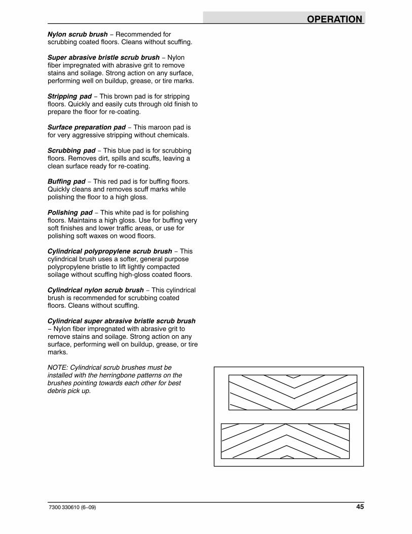
NOTE: Cylindrical scrub brushes must beinstalled with the herringbone patterns on thebrushes pointing towards each other for bestdebris pick up.

OPERATION
7300 330610 (6−09)46
SCRUBBING
1. Start the machine.
FOR SAFETY: When starting machine,keep foot on brake and directional pedalin neutral.
2. Drive the machine to the area to be cleaned.
3. FaST SCRUBBING: Press the FaSTswitch to the desired solution flow. See theFaST SWITCH section of the manual.
NOTE: Leave the FaST switch in theCONVENTIONAL SCRUBBING position if notusing the FaST system.
ec−H2O Scrubbing: Press the ec−H2Oswitch to the desired solution flow. See theec−H2O SWITCH section of the manual.
NOTE:The ec−H2O system indicator light will notturn on until the machine starts scrubbing.
ec−H2O Model: If an alarm sounds and theec−H2O system indicator light begins toblink red, the ec−H2O module must beflushed to resume ec−H2O operation (Seeec−H2O MODULE FLUSH PROCEDURE).
NOTE: When the alarm sounds and the lightblinks red, the machine will bypass the ec−H2Osystem. To continue scrubbing, press the ec−H2Oswitch to conventional scrubbing.
OPERATION
477300 330610 (6−09)
ATTENTION: (ec−H2O model) Do not allowsolution tank to run dry. ec−H2O modulefailure may result if operated without water foran extended period.
ec−H2O SYSTEMINDICATOR LIGHTCODE
CONDITION
Solid green Normal operation
Blinking red Flush ec−H2O module
Solid red Contact Service Center
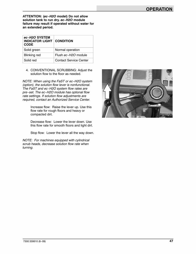
4. CONVENTIONAL SCRUBBING: Adjust thesolution flow to the floor as needed.
NOTE: When using the FaST or ec−H2O system(option), the solution flow lever is nonfunctional.The FaST and ec−H2O system flow rates arepre−set. The ec−H2O module has optional flowrate settings. If solution flow adjustments arerequired, contact an Authorized Service Center.
Increase flow: Raise the lever up. Use thisflow rate for rough floors and heavy orcompacted dirt.
Decrease flow: Lower the lever down. Usethis flow rate for smooth floors and light dirt.
Stop flow: Lower the lever all the way down.
NOTE: For machines equipped with cylindricalscrub heads, decrease solution flow rate whenturning.

OPERATION
7300 330610 (6−09)48
5. Press the scrub switch to start the scrubbingoperations. See the SCRUB SWITCHsection of the manual
WARNING: Flammable materials or reactive metals can cause explosion or fire. Do not pick up.
As long as the machine is moving forwardthe scrub head will lower and the scrubbrushes will start. The optional sweepingside brush(es) will lower and start. The rearsqueegee will lower and the vacuum fan willstart. The solution system will start when themachine first begins to move forward, butonly if the solution flow lever is on. Thedetergent pump will start and the optionalFaST, ec−H20, or ES systems if theswitches are on.
NOTE: The scrub head and optional sweepingside brush(es) will raise when the directional pedalis in the neutral or reverse position. The rearsqueegee will raise when the directional pedal isin the reverse position.
NOTE: If an excess of water in the recovery tanktriggers the ‘tank full’ switch, a tank full alarm willsound for ten seconds and a tank full icon willappear on the control panel. All scrubbingfunctions will be canceled. To make the overflowicon disappear, drain the recovery tank, thenpress the scrub switch.
NOTE: A low battery and a no brush currentsensed will also cancel the scrub system.
6. Adjust brush pressure for cleaningapplication. See the SCRUB SWITCHsection of the manual.
353562
353562

OPERATION
497300 330610 (2−04)
7. Press the edge scrub switch if edgescrubbing is necessary.
8. Adjust detergent flow with detergent flowswitch (option).
9. Press the ES switch (option) if extendedscrubbing is necessary.
NOTE: When using the ES (option), the recoverytank 1/2 full float must be active for the pump tooperate.
NOTE: A full solution tank will turn off the ESpump
NOTE: If you do not want to use the ES system,make sure the indicator next to the ES switch isoff.
353564
353551
353562
353562
OPERATION
7300 330610 (NIL)50
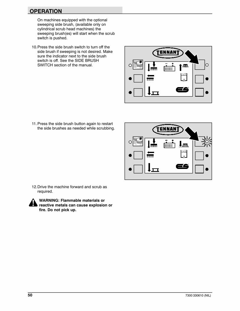
On machines equipped with the optionalsweeping side brush, (available only oncylindrical scrub head machines) thesweeping brush(es) will start when the scrubswitch is pushed.
10.Press the side brush switch to turn off theside brush if sweeping is not desired. Makesure the indicator next to the side brushswitch is off. See the SIDE BRUSHSWITCH section of the manual.
11.Press the side brush button again to restartthe side brushes as needed while scrubbing.
12.Drive the machine forward and scrub asrequired.
WARNING: Flammable materials or reactive metals can cause explosion or fire. Do not pick up.
OPERATION
517300 330610 (6−09)
DOUBLE SCRUBBING
Double scrubbing is the process of making two ormore passes over a heavily soiled area. The firstpass is made with the rear and side squeegeesraised to allow the solution to soak into the floor.
Double scrubbing can be performed using the FaST SCRUBBING SYSTEM (option), ec−H2O SCRUBBING SYSTEM (option) or CONVENTIONAL SCRUBBING methods.
Use the maximum solution and detergent flowsettings. Use a higher brush pressure setting. Letthe solution remain on the floor for 5 to 15minutes, then make a second scrubbing passwith the rear and side squeegees down.
NOTE: When using the FaST or ec−H2O system(option), the solution flow lever is nonfunctional.The FaST and ec−H2O system flow rates arepre−set. The ec−H2O module has optional flowrate settings. If solution flow adjustments arerequired, contact an Authorized Service Center.
FOR SAFETY: When using machine, goslow on inclines and slippery surfaces.
STOP SCRUBBING
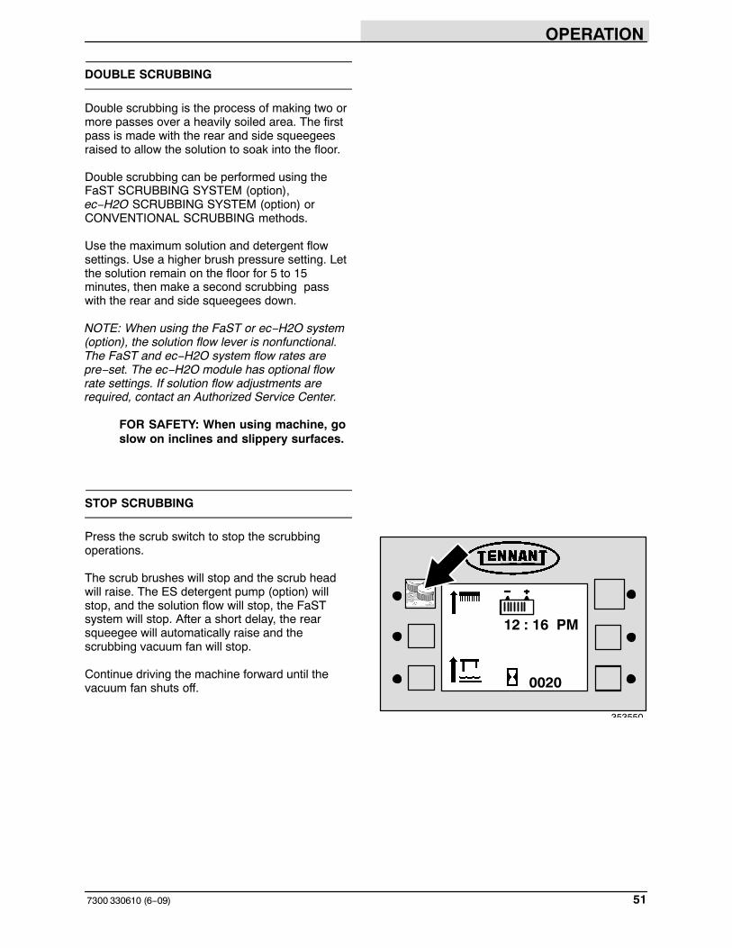
Press the scrub switch to stop the scrubbingoperations.
The scrub brushes will stop and the scrub headwill raise. The ES detergent pump (option) willstop, and the solution flow will stop, the FaSTsystem will stop. After a short delay, the rearsqueegee will automatically raise and thescrubbing vacuum fan will stop.
Continue driving the machine forward until thevacuum fan shuts off. 0020
12 : 16 PM
353550

OPERATION
7300 330610 (6−09)52
DRAINING AND CLEANING THE TANKS
When you are finished scrubbing, or when therecovery tank full indicator comes on, therecovery tank should be drained and cleaned. Thesolution tank can then be filled again for additionalscrubbing.
If you used the machine in ES mode, the solutiontank should also be drained and cleaned whenyou are finished scrubbing.
1. Stop scrubbing.
2. Drive the machine next to an appropriatedisposal site.
3. Turn the machine power off.
FOR SAFETY: Before leaving orservicing machine; stop on levelsurface, set parking brake, turn offmachine and remove key.
4. Set the parking brake.

OPERATION
537300 330610 (6−00)
5. Unscrew the drain hose cap from therecovery tank drain access cap.
6. Pull out and place the drain hose next to thefloor drain. Remove the drain end cap fromthe hose. Stand back because the solutionrushes out of the drain hose.
ES mode: Unscrew the drain hose cap fromthe solution tank drain access cap and drainthe solution tank.
For machines with the positive solutioncontrol drain option, remove the drain capand connect the hose. Place the hose endnext to the floor drain and open the drainvalve by pulling the lever.
7. Open the recovery tank cover.
8. Spray the inside of the recovery tank withclean water. DO NOT allow any water toenter the vacuum fan air intake openingtowards the front of the tank.
NOTE: DO NOT use steam to clean the tanks.Excessive heat can damage the tanks andcomponents.
05914

OPERATION
7300 330610 (2−04)54
9. Remove the large drain cap and flush outthe bottom on the recovery tank.
10. ES mode: Locate the ES cleanout wandunder the battery cover. Remove it andattach it to a water supply hose to use forcleaning.
11. ES mode: Lift up the ES filter by the handleuntil the mesh is exposed and rinse itthoroughly.
12. Rinse off the float sensor(s) on the inside ofthe recovery tank.

OPERATION
557300 330610 (6−00)
13. ES mode: Drain the solution tank. Flush outthe solution tank with clean water. Rinse thesolution outlet filters at the bottom of thetank through the drain access.
14. ES mode: Rinse the sensor float tubes nearthe top of the solution tank.
NOTE: DO NOT use steam to clean the tanks.Excessive heat can damage the tanks andcomponents.
15. Cylindrical scrub head: Press down on theright side squeegee support guard latch untilthe right side squeegee support guardopens. Swing the squeegee support guardaway from the scrub head.

OPERATION
7300 330610 (6−00)56
16. Cylindrical scrub head: Remove and cleanthe debris trough from the right hand side ofthe machine. Place the trough back in thescrub head when clean.
NOTE: The debris trough can be removed fromthe right hand side of the machine only.
17. Remove the vacuum fan filter from therecovery tank cover.
18. Clean the vacuum fan filter by using lowpressure air, or rinsing pleats with lowpressure water.
19. Insert the filter back into the recovery tankcover. Close the tank covers.
20. Place the drain end caps on the tank drainhoses. Push the drain hoses back into thetanks.
For machines with the positive solutioncontrol drain option, close the drain valve.Remove the hose and connect the draincap.

OPERATION
577300 330610 (6−09)
STOP THE MACHINE
1. Stop scrubbing. See the STOPSCRUBBING section of the manual.
2. Take your foot off the directional pedal. Stepon the brake pedal.
NOTE: The machine may coast for a shortdistance when your foot is removed from thedirectional pedal. Use the brake pedal to stop themachine.
3. Turn the machine power off.
4. Set the machine parking brake.
FOR SAFETY: Before leaving orservicing machine; stop on levelsurface, set parking brake, turn offmachine and remove key.
OPERATION
7300 330610 (2−04)58
POST-OPERATION CHECKLIST
Check over this list of items after you havefinished scrubbing with the machine powered on:
� Check the hydraulic fluid level. (if applicable)
� Check the battery fluid and charge level.
� Check the tank cover seals for damage andwear.
� Clean the vacuum fan inlet filter.
� Check the condition of the scrubbingbrushes. Remove any string, banding,plastic wrap, or other debris wrapped around them.
� Check the squeegees for damage, wear andfor deflection adjustment.
� Check the vacuum hose for debris orblockage.
� ES machines; check the detergent tanklevel.
� Drain and clean the recovery tank.
� ES machines; drain and clean the solutiontank and ES filter. Rinse level sensors.
� Check the brakes and steering for properoperation.
� Empty and clean the debris tray. (ifapplicable).
� Check the service records to determinemaintenance requirements.
� FaST Scrubbing: If FaST PAK is empty afterscrubbing, install a new FaST PAK orconnect supply hose to the storage plug.

OPERATION
597300 330610 (6−09)
OPERATION ON INCLINES
Drive the machine slowly on inclines.
FOR SAFETY: When using machine, goslow on inclines and slippery surfaces.
The maximum rated climb and descent inclinewith empty tanks is 8�, and with full tanks is 6�.
OPTIONS
VACUUM WAND
The vacuum wand uses the machine’s vacuumsystem. The vacuum wand and hose allowspick-up of spills that are out of reach of themachine.
WARNING: Flammable materials orreactive metals can cause explosion orfire. Do not pick up.
1. Turn the machine power off.
FOR SAFETY: Before leaving orservicing machine; stop on levelsurface, turn off machine.
2. Set the parking brake.
OPERATION
7300 330610 (6−00)60
3. Remove the vacuum wand equipment fromthe tank cover.
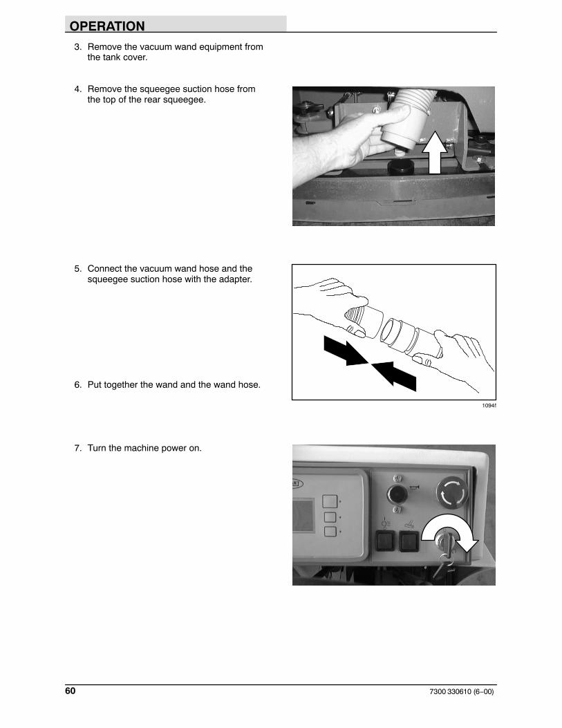
4. Remove the squeegee suction hose fromthe top of the rear squeegee.
5. Connect the vacuum wand hose and thesqueegee suction hose with the adapter.
6. Put together the wand and the wand hose.
7. Turn the machine power on.
10945

OPERATION
617300 330610 (12−00)
8. Press the rear squeegee switch to turn onthe vacuum.
9. Vacuum the floor.
10. When finished, shut off the vacuum with therear squeegee switch.
0020
353565
06599
0020
12 : 16 PM
353550

OPERATION
7300 330610 (6−00)62
11. Turn the machine power off.
12.Disconnect the vacuum hose from thesqueegee suction hose.
13. Reconnect the squeegee suction hose to thetop of the squeegee.
14. Clean and rinse the vacuum wandequipment.
15. Secure the vacuum wand equipment on topof the tank cover.
10946
OPERATION
637300 330610 (6−09)
POWER WAND
The power wand uses the machine’s vacuum andsolution systems. The power wand allowsscrubbing of floors that are out of reach of themachine.
WARNING: Flammable materials orreactive metals can cause explosion orfire. Do not pick up.
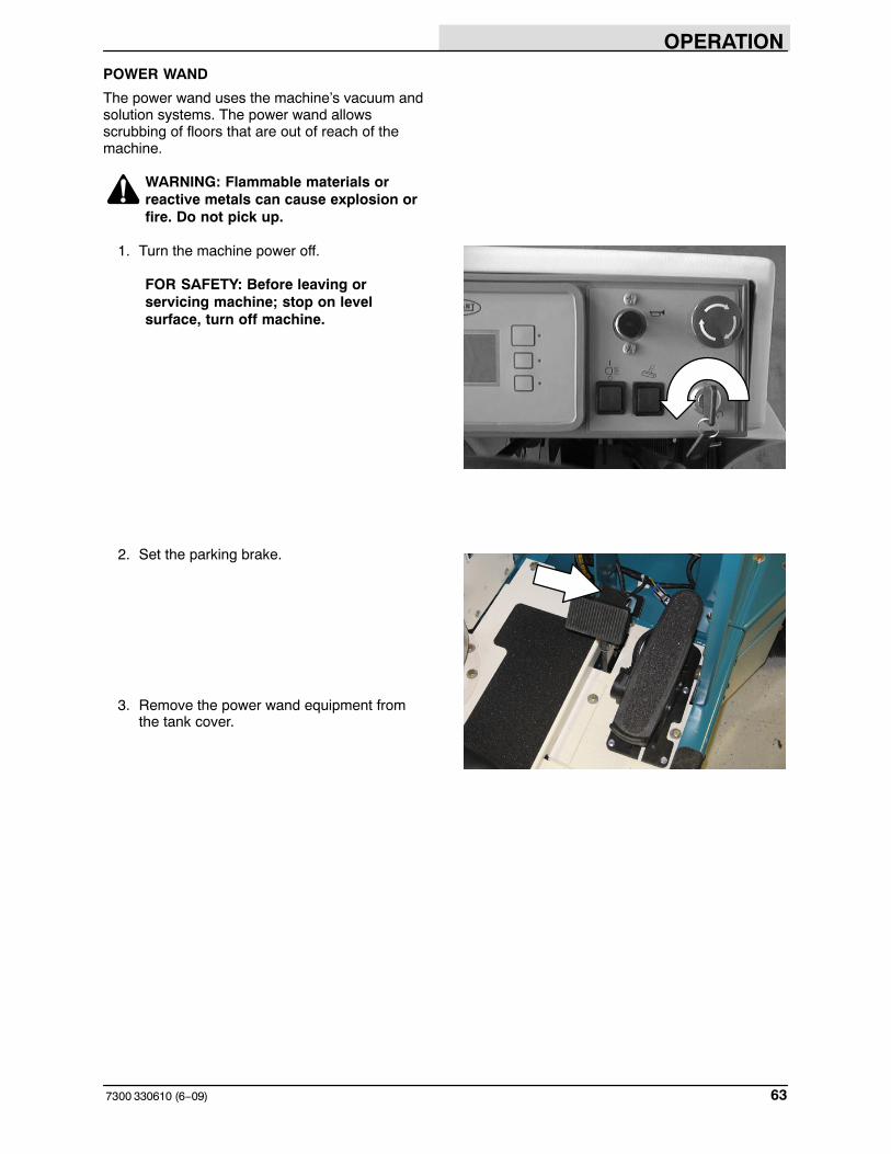
1. Turn the machine power off.
FOR SAFETY: Before leaving orservicing machine; stop on levelsurface, turn off machine.
2. Set the parking brake.
3. Remove the power wand equipment fromthe tank cover.
OPERATION
7300 330610 (6−00)64
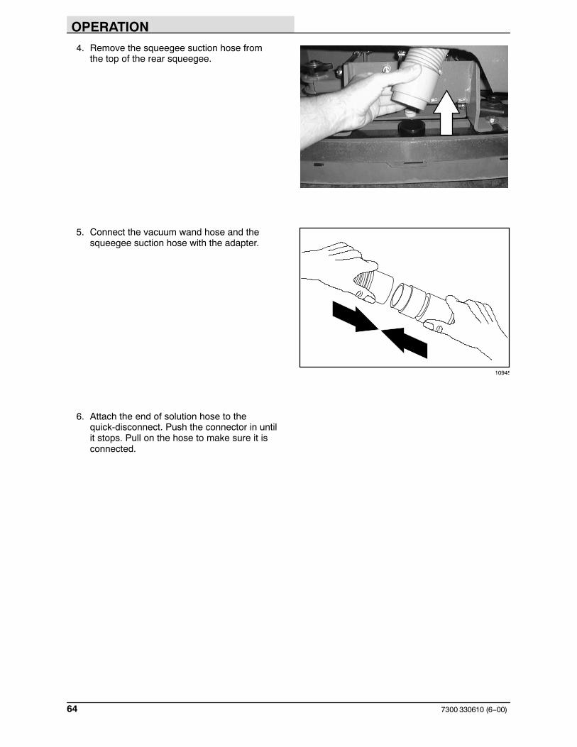
4. Remove the squeegee suction hose fromthe top of the rear squeegee.
5. Connect the vacuum wand hose and thesqueegee suction hose with the adapter.
6. Attach the end of solution hose to thequick-disconnect. Push the connector in untilit stops. Pull on the hose to make sure it isconnected.
10945

OPERATION
657300 330610 (12−00)
7. Attach the other ends of the solution andvacuum hoses to the power wand.
8. Turn the machine power on.
9. Press the rear squeegee switch to turn onthe vacuum.
NOTE: The rear squeegee will also lower.
07320
0020
12 : 16 PM
353565

OPERATION
7300 330610 (6−00)66
10. Press the top of the power wand switch toturn the power wand on.
11. Squeeze the solution lever on the powerwand to spray solution on the floor. Scrubthe floor with the brush side of the cleaningtool.
12. Vacuum up the solution by turning over thecleaning tool so the squeegee side is down.
06601
06202

OPERATION
677300 330610 (12−00)
If the cleaning tool is hard to push or is notpicking up the solution very well, adjust theroller wheels on the tool by turning the blackadjustment knob.
NOTE: The wheels are properly adjusted whenthe squeegee blades deflect slightly while the toolis pushed back and forth.
13. When finished, press the bottom of thepower wand switch to turn off the powerwand.
14. Press the rear squeegee switch to shut offthe vacuum.
06604
0020
12 : 16 PM
353550

OPERATION
7300 330610 (6−00)68
15. Turn the machine power off.
16. Disconnect the solution hose from themachine.
17. Remove the vacuum hose from thesqueegee suction hose.
18. Reconnect the squeegee suction hose to thesqueegee.
19. Disconnect the other ends of the solutionand vacuum hoses from the power wand.
20. Secure the power wand equipment on top ofthe tank cover.
10946
07321

OPERATION
697300 330610 (6−09)
MACHINE TROUBLESHOOTING
Problem Cause Remedy
Trailing water − poor or nowater pickup.
Rear squeegee blades worn Rotate or replace blades
Rear squeegee out of adjustment Adjust rear squeegee
Rear squeegee raised Lower rear squeegee
Rear squeegee tube clogged Flush squeegee tube
Side squeegees raised Lower side squeegees
Side squeegee blades worn Replace side squeegee blades
Side squeegees out of adjustment Adjust side squeegees
Too much solution flow to floor Reduce solution flow to floor
Vacuum hose clogged Flush vacuum hoses
Recovery tank cover not seated Reseat tank cover
Recovery tank cover seal worn Replace seal
Recovery tank full. Drain recovery tank
Float stuck shutting off vacuum Clean float
Debris caught on rear squeegee Remove debris
Foam filling recovery tank Empty recovery tank; use less orchange detergent
Vacuum hose to rear squeegeedisconnected or damaged
Reconnect or replace vacuum hose
Vacuum fan will not turn on Recovery tank full Drain recovery tank
Vacuum fan circuit breaker tripped Reset circuit breaker
Machine in reverse or neutral Propel forward
Vacuum fan failure Contact Tennant servicerepresentative
Little or no solution flow tothe floor.
Solution tank empty Fill solution tank
Solution flow lever off Open solution flow lever
Solution supply lines plugged Flush solution supply lines
ES switch off Turn ES switch on
Manual control valve closed Open valve more
Brush pressure light blinksand changes to a lowerpressure setting.
Brush pressure set to heavy for theapplication
Decrease brush pressure setting
OPERATION
7300 330610 (6−09)70
Problem Cause Remedy
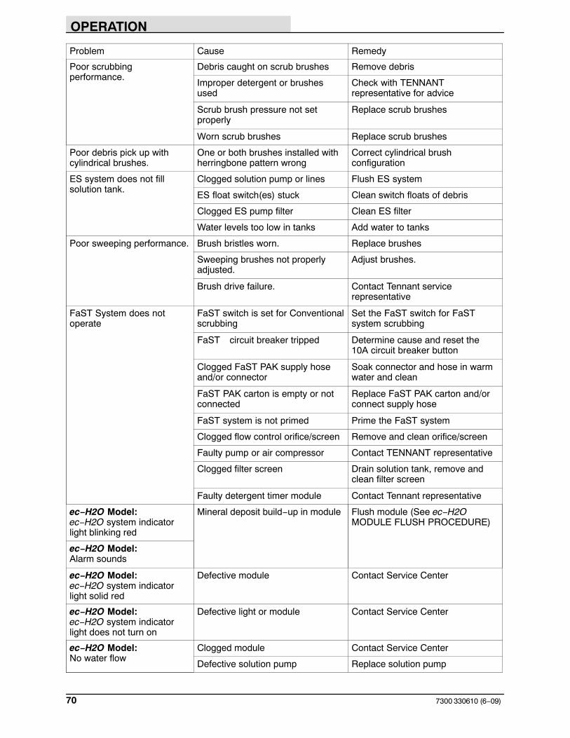
Poor scrubbingperformance.
Debris caught on scrub brushes Remove debris
Improper detergent or brushesused
Check with TENNANTrepresentative for advice
Scrub brush pressure not setproperly
Replace scrub brushes
Worn scrub brushes Replace scrub brushes
Poor debris pick up withcylindrical brushes.
One or both brushes installed withherringbone pattern wrong
Correct cylindrical brushconfiguration
ES system does not fillsolution tank.
Clogged solution pump or lines Flush ES system
ES float switch(es) stuck Clean switch floats of debris
Clogged ES pump filter Clean ES filter
Water levels too low in tanks Add water to tanks
Poor sweeping performance. Brush bristles worn. Replace brushes
Sweeping brushes not properlyadjusted.
Adjust brushes.
Brush drive failure. Contact Tennant servicerepresentative
FaST System does notoperate
FaST switch is set for Conventionalscrubbing
Set the FaST switch for FaSTsystem scrubbing
FaST circuit breaker tripped Determine cause and reset the10A circuit breaker button
Clogged FaST PAK supply hoseand/or connector
Soak connector and hose in warmwater and clean
FaST PAK carton is empty or notconnected
Replace FaST PAK carton and/orconnect supply hose
FaST system is not primed Prime the FaST system
Clogged flow control orifice/screen Remove and clean orifice/screen
Faulty pump or air compressor Contact TENNANT representative
Clogged filter screen Drain solution tank, remove andclean filter screen
Faulty detergent timer module Contact Tennant representative
ec−H2O Model:ec−H2O system indicatorlight blinking red
Mineral deposit build−up in module Flush module (See ec−H2OMODULE FLUSH PROCEDURE)
ec−H2O Model:Alarm sounds
ec−H2O Model: ec−H2O system indicatorlight solid red
Defective module Contact Service Center
ec−H2O Model: ec−H2O system indicatorlight does not turn on
Defective light or module Contact Service Center
ec−H2O Model: No water flow
Clogged module Contact Service Center
Defective solution pump Replace solution pump

MAINTENANCE
717300 330610 (2−04)
MAINTENANCE
1
1 2
3
4
5
61 7
88
9
710
11
11
12
12
12
13
14
15
15
16
16 17
18
1920
21
MAINTENANCE CHART
NOTE: Check procedures indicated (�) after the first 50-hours of operation.
Interval Key Description ProcedureLubricant/
Fluid
No. ofServicePoints
Daily 1 Rear and side squeegees Check for damage, wear and adjustment
− 3− 1
2 Scrub brushes Check for damage and wear − 2Check for debris − 2
20 Side brush(es) (option) Check for damage and wear − 1, 2Check for debris − 1, 2
3 Recovery tank Clean − 13 Recovery tank, ES mode Clean ES filter − 14 Solution tank, ES mode Clean and flush − 15 Vacuum fan filter Clean and flush − 16 Debris trough
(Cylindrical brushes only)Check and clean − 1
21 FaST PAK supply hoseand connector
Clean and connect hose to stor-ing plug when not in use
− 1
− Machine Check for leaks − 1
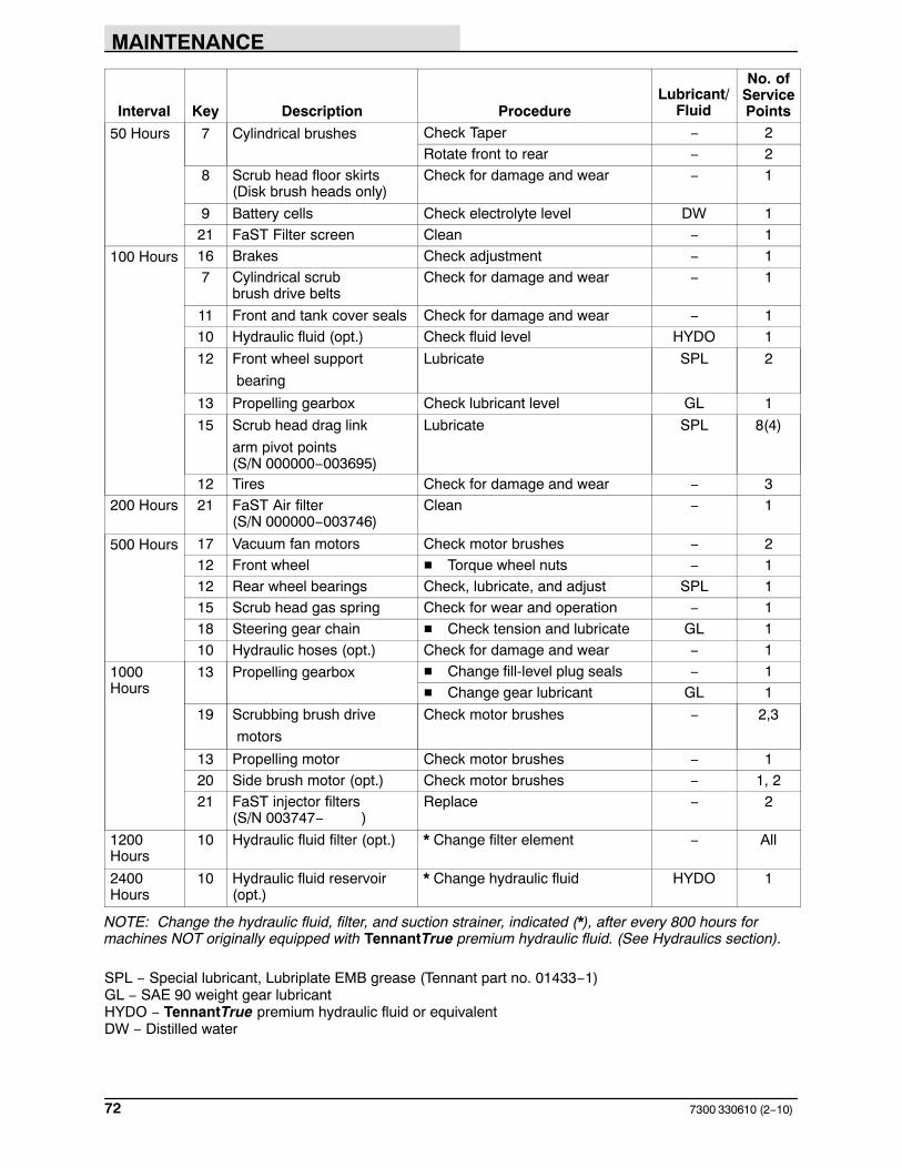
MAINTENANCE
7300 330610 (2−10)72
Interval Key Description ProcedureLubricant/
Fluid
No. ofServicePoints
50 Hours 7 Cylindrical brushes Check Taper − 2Rotate front to rear − 2
8 Scrub head floor skirts (Disk brush heads only)
Check for damage and wear − 1
9 Battery cells Check electrolyte level DW 121 FaST Filter screen Clean − 1
100 Hours 16 Brakes Check adjustment − 17 Cylindrical scrub
brush drive beltsCheck for damage and wear − 1
11 Front and tank cover seals Check for damage and wear − 110 Hydraulic fluid (opt.) Check fluid level HYDO 1
12 Front wheel support
bearing
Lubricate SPL 2
13 Propelling gearbox Check lubricant level GL 1
15 Scrub head drag link
arm pivot points(S/N 000000−003695)
Lubricate SPL 8(4)
12 Tires Check for damage and wear − 3200 Hours 21 FaST Air filter
(S/N 000000−003746)Clean − 1
500 Hours 17 Vacuum fan motors Check motor brushes − 212 Front wheel � Torque wheel nuts − 112 Rear wheel bearings Check, lubricate, and adjust SPL 115 Scrub head gas spring Check for wear and operation − 118 Steering gear chain � Check tension and lubricate GL 110 Hydraulic hoses (opt.) Check for damage and wear − 1
1000Hours
13 Propelling gearbox � Change fill-level plug seals − 1� Change gear lubricant GL 1
19 Scrubbing brush drive
motors
Check motor brushes − 2,3
13 Propelling motor Check motor brushes − 120 Side brush motor (opt.) Check motor brushes − 1, 221 FaST injector filters
(S/N 003747− )Replace − 2
1200Hours
10 Hydraulic fluid filter (opt.) * Change filter element − All
2400Hours
10 Hydraulic fluid reservoir(opt.)
* Change hydraulic fluid HYDO 1
NOTE: Change the hydraulic fluid, filter, and suction strainer, indicated (*), after every 800 hours formachines NOT originally equipped with TennantTrue premium hydraulic fluid. (See Hydraulics section).
SPL − Special lubricant, Lubriplate EMB grease (Tennant part no. 01433−1)GL − SAE 90 weight gear lubricantHYDO − TennantTrue premium hydraulic fluid or equivalentDW − Distilled water

MAINTENANCE
737300 330610 (6−00)
LUBRICATION
PROPELLING GEARBOX
Check the lubricant level in the propelling gearboxevery 100 hours of operation. Change the gearlubricant, and the drain and fill-level plug sealsafter the first 50 hours of operation, and thenevery 1000 hours of operation. Use SAE 90weight gear lubricant.
FOR SAFETY: When servicing machine,block machine tires before jackingmachine up.
FRONT WHEEL SUPPORT BEARING
The front wheel support has two grease fittings forthe bearing. Raise the machine so the front wheelis off the floor. Fill one of the grease fittings whilerotating the gearbox from stop to stop. Fill thesecond grease fitting while rotating the gearboxback to the original position. The bearing cavity isfull when grease comes out of the fittings, or outof the top seal.
Lubricate with Lubriplate EMB grease (Tennantpart no. 01433−1) every 100 hours of machineoperation, or after steam cleaning the gearboxarea.
FOR SAFETY: When servicing machine,use hoist or jack that will support theweight of the machine.
FOR SAFETY: When servicing machine,jack machine up at designated locationsonly. Block machine up with jackstands.
05934
05934

MAINTENANCE
7300 330610 (6−09)74
SCRUB HEAD DRAG LINK ARMS(S/N 000000−003695)
The scrub head drag link arms have a greasefitting at each of the pivot points. Lubricate withLubriplate EMB grease (Tennant Part No.01433−1) every 100 hours of operation.
The MaxPro 1000 disk scrub head has four linkarms that need lubrication.
The Maxpro 1200 disk scrub head has two linkarms that need lubrication.

MAINTENANCE
757300 330610 (12−01)
The Maxpro 1000 and the Maxpro 1200 cylindricalscrub heads each have two arms that needlubrication.
REAR WHEEL BEARINGS
Inspect the rear wheel bearings for seal damage,and repack and adjust every 500 hours ofoperation. Use Lubriplate EMB grease (Tennantpart number 01433−1).
STEERING GEAR CHAIN
The steering gear chain is located by the footpedals. Lubricate the chain with SAE 90 weightgear lubricant after the first 50, and then afterevery 500 hours of operation.

MAINTENANCE
7300 330610 (2−10)76
HYDRAULICS (OPTION)
HYDRAULIC FLUID RESERVOIR
The hydraulic reservoir holds the hydraulic fluidfor the power steering option. It is locatedunderneath the front cover of the machine. A fillercap is mounted on top of the reservoir.
Check the hydraulic fluid level at operatingtemperature after every 100 hours of operation.The reservoir should be filled to 2” +/− .5” belowthe top of the reservoir. The top of the springassembly that holds down the filter inside thereservoir can be used as a gauge.
Lubricate the filler cap gasket with a film ofhydraulic fluid before putting the cap back on thereservoir.
ATTENTION! Do not overfill thehydraulic fluid reservoir or operate themachine with a low level of hydraulicfluid in the reservoir. Damage to themachine hydraulic system may result.
Drain and refill the hydraulic fluid reservoir withnew TennantTrue premium hydraulic fluid afterevery 2400 hours of operation. Machines have ablue colored drop (left photo) on the hydraulic fluidlabel if originally equipped with TennantTruepremium hydraulic fluid.
TennantTrue Fluid Previous Fluid
NOTE: Change the hydraulic fluid, filter, andsuction strainer after every 800 hours for ALLmachines that have NOT consistently usedTennantTrue premium hydraulic fluid orequivalent.
The reservoir has a built−in filter outlet that filtershydraulic fluid before it enters the system.Replace the filter every 1200 hours of operation.

MAINTENANCE
777300 330610 (2−10)
HYDRAULIC FLUID
TennantTrue premium hydraulic fluid (Extended Life)
Part number ISO Grade Capacity
1057707 32 3.8 L (1 gal)
1057708 32 19 L (5 gal)
If using a locally−available hydraulic fluid, be surethe specifications match the Tennant hydraulicfluid specifications. Substitute fluids can causepremature failure of hydraulic components.
ATTENTION! Hydraulic componentsdepend on system hydraulic fluid forinternal lubrication. Malfunctions,accelerated wear, and damage will resultif dirt or other contaminants enter thehydraulic system.
HYDRAULIC HOSES
Check the hydraulic hoses after every 500 hoursof operation for wear or damage.
Fluid escaping at high pressure from a very smallhole can be almost invisible, and can causeserious injuries.
See a doctor at once if injury results fromescaping hydraulic fluid. Serious infection orreaction can develop if proper medical treatmentis not given immediately.
FOR SAFETY: When servicing machine,use cardboard to locate leakinghydraulic fluid under pressure.
If you discover a fluid leak, contact your mechanicor supervisor.
00002

MAINTENANCE
7300 330610 (7−00)78
BATTERIES
The batteries are unique in that they hold theirpower for long periods of time. The lifetime of thebatteries is limited by the number of charges thebatteries receive. To get the most life from thebatteries, charge them when all the batterydischarge indicator segments shut off (20%charge left). Use an automatic charger with theproper rating for the batteries.
Periodically clean the top surface of the batteriesand terminals with a strong solution of bakingsoda and water. Brush the solution sparingly overthe battery tops, terminals, and cable clamps. Donot allow any baking soda solution to enter thebatteries. Use a wire brush to clean the terminalposts and the cable connectors. After cleaning,apply a coating of clear battery post protectant tothe terminals and the cable connectors. Check thebatteries for loose connections. Keep the tops ofthe batteries clean and dry.
Keep all metallic objects off the top of thebatteries, which may cause a short circuit.Replace any worn or damaged wires.
Check the electrolyte level in each battery cellbefore and after charging, and after every 50hours of operation. Do not charge the batteriesunless the fluid is slightly above the battery plates.If needed, add just enough distilled water to coverthe plates. Never add acid to the batteries. Do notoverfill. Always keep the battery caps on, exceptwhen adding water or taking hydrometer readings.
Measuring the specific gravity, using ahydrometer, is a way to determine the chargelevel and condition of the batteries. If one or moreof the battery cells test lower than the otherbattery cells (0.050 or more), the cell is damaged,shorted, or is about to fail.
0020
12 : 16 PM
353550
04380

MAINTENANCE
797300 330610 (6−09)
NOTE: Do not take readings immediately afteradding distilled water. If the water and acid are notthoroughly mixed, the readings may not beaccurate. Check the hydrometer readings againstthe following chart to determine the remainingbattery charge level:
SPECIFIC GRAVITY at27� C (80� F)
BATTERYCHARGE
1.290 100% Charged
1.252 75% Charged
1.200 50% Charged
1.177 25% Charged
1.140 Discharged
NOTE: If the readings are taken when the batteryelectrolyte is any temperature other than 27� C(80� F), the reading must be temperaturecorrected. Add or subtract to the specific gravityreading 0.004, 4 points, for each 6� C(10� F)above or below 27�C(80� F).
NOTE: For machines with the rollout batteryoption, remove the cable tie before removingbatteries.
CHARGING THE BATTERIES
1. Drive the machine to a flat, dry surface in awell-ventilated area.
2. Turn the machine power off and set theparking brake.
FOR SAFETY: Before leaving orservicing machine; stop on levelsurface, turn off machine.
3. Open the top battery compartment cover.The support arm will engage when the coveris lifted all the way up.
WARNING: Batteries emit hydrogengas. Explosion or fire can result. Keepsparks and open flame away. Keepcovers open when charging.
4. Open the rear battery compartment door.

MAINTENANCE
7300 330610 (5−01)80
5. Check the electrolyte level in all the batterycells.
6. If the level is low, add just enough distilledwater to cover the plates. DO NOTOVERFILL. The batteries can overflowduring charging due to expansion.
NOTE: Make sure the battery caps are in placewhile charging.
FOR SAFETY: When maintaining orservicing machine, avoid contact withbattery acid.
7. Unplug the battery connector from themachine connector.
8. Plug the charger connector into the batteryconnector.
9. Plug the battery charger into the wall outlet.
NOTE: If the red “ABNORMAL CYCLE” lamplights when the TENNANT charger is plugged intoa wall outlet, the charger can not charge thebattery and there is something wrong with thebattery.
10.The Tennant charger will start automatically.When the batteries are fully charged, theTennant charger will automatically turn off.
NOTE: Use a charger with the proper rating forthe batteries to prevent damage to the batteries orreduce the battery life.
NOTE: If the charger needs to be disconnectedfrom the machine before the batteries are fullycharged and the charger has not automaticallyshut off, turn off the charger before disconnectingit.
08247
07224
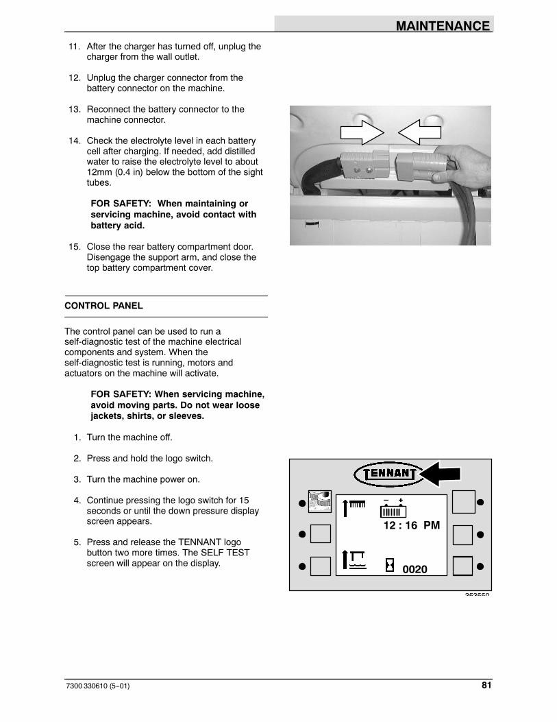
MAINTENANCE
817300 330610 (5−01)
11. After the charger has turned off, unplug thecharger from the wall outlet.
12. Unplug the charger connector from thebattery connector on the machine.
13. Reconnect the battery connector to themachine connector.
14. Check the electrolyte level in each batterycell after charging. If needed, add distilledwater to raise the electrolyte level to about12mm (0.4 in) below the bottom of the sighttubes.
FOR SAFETY: When maintaining orservicing machine, avoid contact withbattery acid.
15. Close the rear battery compartment door.Disengage the support arm, and close thetop battery compartment cover.
CONTROL PANEL
The control panel can be used to run aself-diagnostic test of the machine electricalcomponents and system. When theself-diagnostic test is running, motors andactuators on the machine will activate.
FOR SAFETY: When servicing machine,avoid moving parts. Do not wear loosejackets, shirts, or sleeves.
1. Turn the machine off.
2. Press and hold the logo switch.
3. Turn the machine power on.
4. Continue pressing the logo switch for 15seconds or until the down pressure displayscreen appears.
5. Press and release the TENNANT logobutton two more times. The SELF TESTscreen will appear on the display.
0020
12 : 16 PM
353550
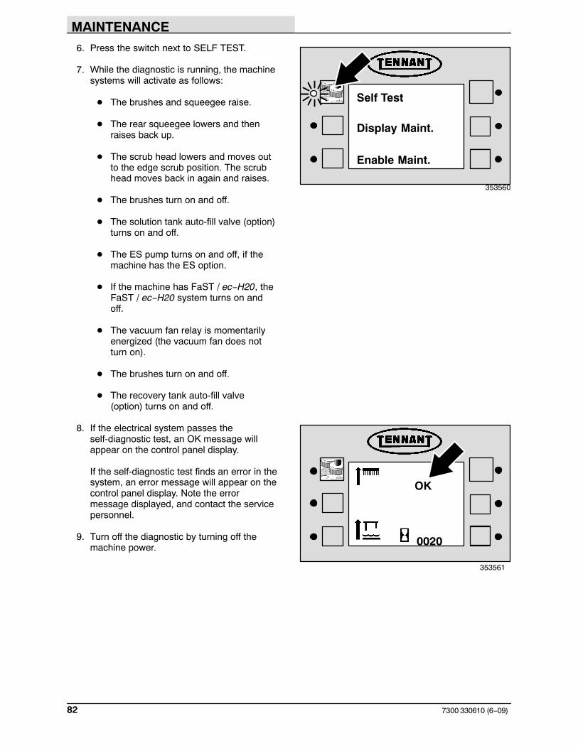
MAINTENANCE
7300 330610 (6−09)82
6. Press the switch next to SELF TEST.
7. While the diagnostic is running, the machinesystems will activate as follows:
� The brushes and squeegee raise.
� The rear squeegee lowers and thenraises back up.
� The scrub head lowers and moves outto the edge scrub position. The scrubhead moves back in again and raises.
� The brushes turn on and off.
� The solution tank auto-fill valve (option)turns on and off.
� The ES pump turns on and off, if themachine has the ES option.
� If the machine has FaST / ec−H20, theFaST / ec−H20 system turns on andoff.
� The vacuum fan relay is momentarilyenergized (the vacuum fan does notturn on).
� The brushes turn on and off.
� The recovery tank auto-fill valve(option) turns on and off.
8. If the electrical system passes theself-diagnostic test, an OK message willappear on the control panel display.
If the self-diagnostic test finds an error in thesystem, an error message will appear on thecontrol panel display. Note the errormessage displayed, and contact the servicepersonnel.
9. Turn off the diagnostic by turning off themachine power.
Self Test
Display Maint.
Enable Maint.
353560
0020
353561
OK

MAINTENANCE
837300 330610 (6−00)
ELECTRIC MOTORS
The carbon brushes on the vacuum fan motorsshould be inspected every 500 hours of machineoperation. The brush drive motors and propellingmotor should be inspected every 1000 hours ofoperation.
PROPELLING CIRCUIT
The propelling circuit is a transistorized controller.It controls the forward and reverse speed of themachine and is located in the controller panel.The circuit cannot be serviced by the user − onlytrained personnel should be allowed to work on it.Do not steam clean or spray the panel with waterbecause the electrical system may be damaged.
NOTE: A static discharge grounding strap shouldbe used when servicing the electronic circuitry.

MAINTENANCE
7300 330610 (5−01)84
SCRUB HEAD
The machine can be equipped with either disk orcylindrical heads. There are two scrub headwidths available for each type of scrub head. Thescrub head floor skirts control water spray fromthe brushes.
The MaxPro 1000 disk scrub head contains twodisk scrub brushes, and is available with standardor heavy duty scrubbing motors. The MaxPro 1000 disc head has a 1020 mm (40in) scrubbing path. The MaxPro 1200 disc head has three disks, anda 1220 mm (48 in) path.
The MaxPro 1000 cylindrical head has a 1020 mm (40 in) scrubbing path, and theMaxPro 1200 cylindrical head has a 1220 mm (48 in) path.
SCRUB HEAD GAS SPRING
Check the scrub head gas spring for wear andproper operation every 500 hours of operation.
SCRUB HEAD ADJUSTMENTS
The cylindrical scrub head is factory adjusted, andthe measurements should not be changed unlessscrub head parts are damaged or are replaced.

MAINTENANCE
857300 330610 (6−09)
SCRUB BRUSHES
The machine can be equipped with either disk orcylindrical scrub brushes. Check scrub brushesdaily for wire or string tangled around the brush orbrush drive hub. Also check for brush damageand wear.
DISK BRUSHES
Replace the brushes when they no longer cleaneffectively.
NOTE: Replace worn brushes in sets. Scrubbingwith brushes of unequal bristle length will result indiminished scrubbing performance.
REPLACING THE DISK BRUSHES
1. Raise the scrub head.
2. Turn the machine power off and set theparking brake.
FOR SAFETY: Before leaving orservicing machine, stop on levelsurface, set parking brake, turn offmachine, and remove key.
3. Raise the side squeegee and lock in the upposition using the side squeegee doublescrub latches.
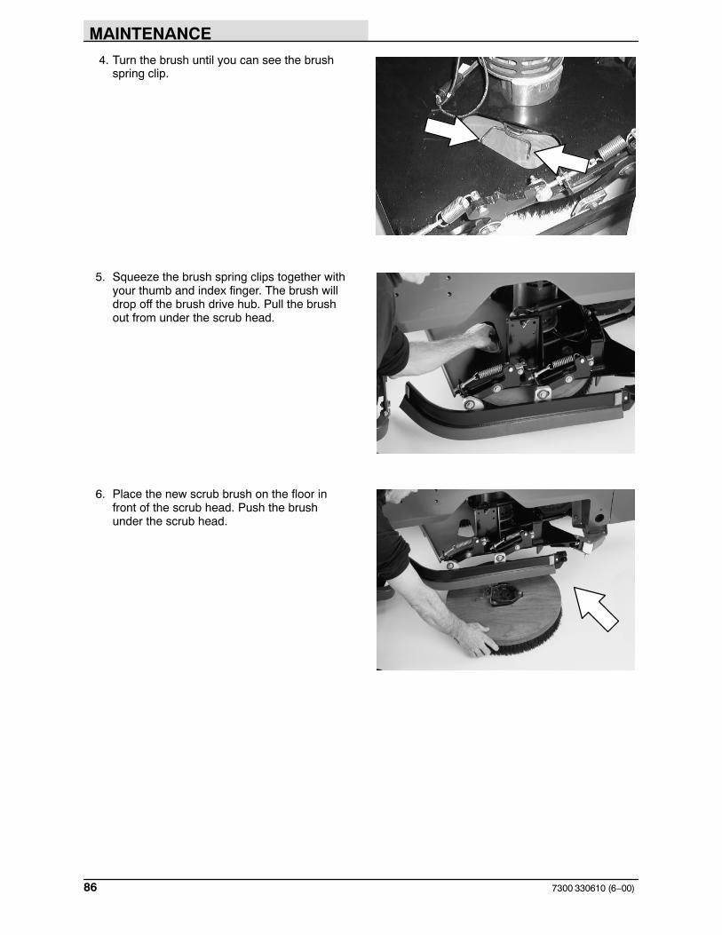
MAINTENANCE
7300 330610 (6−00)86
4. Turn the brush until you can see the brushspring clip.
5. Squeeze the brush spring clips together withyour thumb and index finger. The brush willdrop off the brush drive hub. Pull the brushout from under the scrub head.
6. Place the new scrub brush on the floor infront of the scrub head. Push the brushunder the scrub head.

MAINTENANCE
877300 330610 (6−00)
7. Line up the brush drive socket with the driveplug.
8. While squeezing the brush spring cliptogether with your thumb and index finger,lift the scrub brush onto the drive plug.
9. Check to make sure the brush is securelymounted on the brush drive hub.
10.Lift up on the side squeegee while releasingthe side squeegee double scrub latches.Lower the side squeegee to the downposition.
11.Repeat for the other brush.

MAINTENANCE
7300 330610 (6−09)88
CYLINDRICAL BRUSHES
Check the brush taper and rotate the brushesfrom front-to-rear every 50 hours of machineoperation for maximum brush life and bestscrubbing performance. Check and clean thecylindrical head debris trough daily.
Replace the brushes when they no longer cleaneffectively.
NOTE: Replace worn brushes in pairs. Scrubbingwith brushes of unequal bristle length will result indiminished scrubbing performance.
NOTE: Fill the solution tank before checking oradjusting the brush pattern.
CHECKING AND ADJUSTING CYLINDRICALBRUSH PATTERN
1. Apply chalk (or another material that will noteasily blow away), to a smooth, level sectionof the floor.
2. Set the parking brake.
3. Lower the scrub head in the chalked area.Allow the machine to scrub in the sameplace for 15 to 20 seconds.
NOTE: If chalk or other material is not available,allow the brushes to spin on the floor for twominutes. A polish mark will remain on the floor.
4. Raise the scrub head and move the machineaway from the chalked area. Turn themachine power off.

MAINTENANCE
897300 330610 (6−00)
5. Observe the shape of the brush patterns. Ifthe brush patterns have parallel sides, thebrushes do not need adjustment.
If one, or both of the brush patterns aretapered, the brushes need adjustment tostraighten the brush pattern.
A. Open the side squeegee support doorwith the latch. Swing the support dooroutward to access the idler supportcover.
B. Loosen the larger mounting screw onthe outside of the idler door.
10355
10356

MAINTENANCE
7300 330610 (6−00)90
C. Raise or lower the end of the brush withthe smaller brush adjustment screw asneeded to straighten the brush pattern.
D. Tighten the mounting screw to securethe brush.
E. Close the side squeegee support door.Check the brush patterns again andreadjust as necessary until bothpatterns are the same.
6. If one brush pattern is wider than the other,the scrub head needs to be leveled.
Level the scrub head by turning the topscrub head drag link arm on both sides ofthe scrub head.
Check the brush patterns again and readjustas necessary until both patterns are thesame.
350630

MAINTENANCE
917300 330610 (5−01)
REPLACING THE CYLINDRICAL BRUSHES
1. Press the scrubbing switch. When the scrubhead is approximately 25 mm (1 in) from thefloor, turn the machine power off.
2. Set the parking brake.
FOR SAFETY: Before leaving orservicing machine, stop on levelsurface, set parking brake, turn offmachine, and remove key.
3. Open the side squeegee support door withthe latch. Swing the support door outward toaccess the idler support cover.
4. Lift up on the idler support latch to releasethe idler support cover.
5. Pull the idler plug off the brush, and pull theold brush out of the scrub head.

MAINTENANCE
7300 330610 (7−00)92
6. Position the brush with the double row endtowards you. Guide the new brush onto thedrive hub.
7. Insert the Idler plug (on the inside of the idlersupport cover), into the brush.
NOTE: Cylindrical scrub brushes must beinstalled with the herringbone patterns on thebrushes pointing towards each other for bestdebris pick up.
8. Secure the idler support cover with the idlersupport latch.
9. Firmly close the side squeegee supportdoor. Check that the door bumper is tightagainst the debris tray.
10.Repeat for the other brush on the other sideof the scrub head.

MAINTENANCE
937300 330610 (6−09)
SIDE SWEEPING BRUSH (OPTION)
The side sweeping brush(es) sweep debris intothe path of the cylindrical scrub brush. Check theside brush(es) daily for wear or damage. Removeany string or wire found tangled on the sidebrush(es) or side brush drive shafts.
The side sweeping brush(es) pattern should bechecked periodically. The side brush bristlesshould contact the floor in a 10 o’clock to 3 o’clockpattern when the brush is in motion. The sidebrush pattern adjustment is made by turning theside brush adjustment knob.
Replace the brush(es) when they no longer cleaneffectively
REPLACING AND ADJUSTING THE SIDESWEEPING BRUSH(ES)
1. Turn the machine power off and set theparking brake.
FOR SAFETY: Before leaving orservicing machine; stop on levelsurface, set parking brake, turn offmachine and remove key.
2. Remove the retaining hardware mountingthe side brush to the side brush drive shaft.
3. Slide the side brush off the side brush driveshaft.
4. Slide the new side brush onto the side brushdrive shaft.
5. Mount the new side brush to the drive shaftwith the mounting hardware.
6. Lower the hopper assembly
7. Check the side brush pattern. To increasethe bristle contact with the floor, turn theside brush adjustment knob counter−clockwise. To decrease, turn the side brushadjustment knob clockwise.
03376

MAINTENANCE
7300 330610 (6−00)94
SOLUTION SYSTEM
SOLUTION VALVE
The solution valve controls the flow of solution tothe scrub brushes. The valve linkage shouldprovide the valve with fully open to fully closedpositions.
The solution control cable can be adjusted at thesolution lever or valve ends of the cable. To adjustthe cable at the solution lever end, open themachine cover. To adjust the cable at the solutionvalve end of the cable, locate the valve by thescrub head. Adjust the cable with the valve in theoff position.
The solution lever has two mounting holes for thesolution cable clevis. In the factory, the cable ismounted on the inside hole. The cable clevis canbe moved to the outside hole for greater solutionflow to the floor. This mounting position would befor rough floor conditions only.
RECOVERY TANK
The recovery tank stores recovered solution.
The recovery tank should be drained and cleaneddaily, after the solution tank is empty, wheneverthe float stops the vacuum fan, or the recoverytank full indicator lights. See DRAINING ANDCLEANING THE TANKS section of this manual.
352716

MAINTENANCE
957300 330610 (6−00)
The vacuum fan filter should be cleaned daily.See DRAINING AND CLEANING THE TANKSsection of this manual.
ES option: The ES filter should be cleaned daily.
The outside of the tank can be cleaned with vinylcleaner.
SOLUTION TANK
The solution tank stores the cleaning solution.
The solution tank does not require regularmaintenance. If deposits form on the bottom ofthe tank, rinse the tank with a strong blast ofwarm water. The tank can be flushed through thefill opening. Drain the tank with the solution tankdrain hose. See DRAINING AND CLEANINGTHE TANKS section of this manual.
ES option: The solution tank should be drainedand cleaned daily. Rinse the solution outlet filtersat the bottom of the tank through the drainaccess.

MAINTENANCE
7300 330610 (6−09)96
FaST SYSTEM
FaST SUPPLY HOSE CONNECTOR
The FaST supply hose connector is located belowthe FaST PAK holder. Soak the connector inwarm water if detergent buildup is visible. When aFaST PAK carton is not installed, store the supplyhose connector on the storing plug to prevent thehose from clogging.
FaST SYSTEM FILTER SCREEN
The FaST system filter screen is located underthe solution tank and filters the water from thesolution tank as it flows into the FaST system.
Remove the filter screen bowl and clean the filterscreen after every 50 hours of machine operation.Empty the solution tank before removing the filter.
FaST SYSTEM AIR PUMP FILTER(S/N 000000−003746)
The FaST system air pump filter is located on theside of the air pump.
Remove and clean out the air filter withcompressed air after every 200 hours of FaSTscrubbing.
FOR SAFETY: When servicing machine,wear eye protection when usingpressurized air or water.

MAINTENANCE
977300 330610 (6−2012)
FaST SYSTEM AIR PUMP FILTER(S/N 003747− )
The FaST system injector filters are located underthe FaST−PAK holder.
Replace the FaST system injector filters afterevery 1000 hours of operation. Empty the solutiontank before replacing the filters.

MAINTENANCE
7300 330610 (6−09)98
ec−H2O MODULE FLUSH PROCEDURE
This procedure is only required when an alarmsounds and the ec−H2O system indicator lightbegins to blink red.
1. Remove the siphon hose from the retainer.
2. Disconnect the ec−H2O system intake hosefrom the solution supply hose and theec−H2O system outlet hose from the hoseto the scrub head.
3. Connect the siphon hose to the ec−H2Osystem intake hose and place the siphonhose into container containing 2 gallons (7.6liters) of white or rice vinegar.
NOTE: Use white or rice vinegar only. Theacidity level should be between 4−8%. Do notuse other acids for this procedure.
FOR SAFETY: When servicing machine,wear protective gloves and eyeprotection when handling vinegar.
4. Place the ec−H2O system intake hose into aempty bucket.
5. Turn the key to the on ( I ) position.
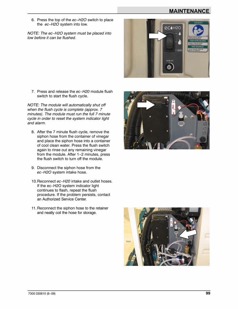
MAINTENANCE
997300 330610 (6−09)
6. Press the top of the ec−H2O switch to placethe ec−H2O system into low.
NOTE: The ec−H2O system must be placed intolow before it can be flushed.
7. Press and release the ec−H20 module flushswitch to start the flush cycle.
NOTE: The module will automatically shut offwhen the flush cycle is complete (approx. 7minutes). The module must run the full 7 minutecycle in order to reset the system indicator lightand alarm.
8. After the 7 minute flush cycle, remove thesiphon hose from the container of vinegarand place the siphon hose into a containerof cool clean water. Press the flush switchagain to rinse out any remaining vinegarfrom the module. After 1−2 minutes, pressthe flush switch to turn off the module.
9. Disconnect the siphon hose from theec−H2O system intake hose.
10.Reconnect ec−H20 intake and outlet hoses.If the ec−H2O system indicator lightcontinues to flash, repeat the flushprocedure. If the problem persists, contactan Authorized Service Center.
11.Reconnect the siphon hose to the retainerand neatly coil the hose for storage.
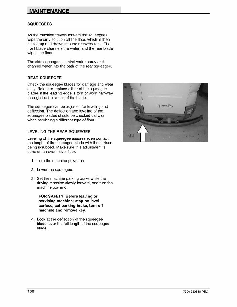
MAINTENANCE
7300 330610 (NIL)100
SQUEEGEES
As the machine travels forward the squeegeeswipe the dirty solution off the floor, which is thenpicked up and drawn into the recovery tank. Thefront blade channels the water, and the rear bladewipes the floor.
The side squeegees control water spray andchannel water into the path of the rear squeegee.
REAR SQUEEGEE
Check the squeegee blades for damage and weardaily. Rotate or replace either of the squeegeeblades if the leading edge is torn or worn half-waythrough the thickness of the blade.
The squeegee can be adjusted for leveling anddeflection. The deflection and leveling of thesqueegee blades should be checked daily, orwhen scrubbing a different type of floor.
LEVELING THE REAR SQUEEGEE
Leveling of the squeegee assures even contactthe length of the squeegee blade with the surfacebeing scrubbed. Make sure this adjustment isdone on an even, level floor.
1. Turn the machine power on.
2. Lower the squeegee.
3. Set the machine parking brake while thedriving machine slowly forward, and turn themachine power off.
FOR SAFETY: Before leaving orservicing machine; stop on levelsurface, set parking brake, turn offmachine and remove key.
4. Look at the deflection of the squeegeeblade, over the full length of the squeegeeblade.

MAINTENANCE
1017300 330610 (6−00)
5. If the deflection is not the same over the fulllength of the blade, adjust the deflection byturning the leveling adjustment screw.
Turn the leveling adjustment screwclockwise to increase the deflection at theends of the squeegee blade.
Turn the leveling adjustment screwcounter-clockwise to decrease the deflectionat the ends of the squeegee blade.
6. Release the parking brake and drive themachine forward again with the squeegeedown to check the squeegee bladedeflection.
7. Readjust the squeegee level if necessary.
ADJUSTING REAR SQUEEGEE BLADEDEFLECTION
Deflection is the amount of curl the squeegeeblade has when the machine moves forward withthe squeegee lowered to the floor. The bestdeflection is when the squeegee wipes the floorjust dry with a minimum amount of deflection.
1. Turn the machine power on.
2. Lower the squeegee.
3. Set the machine parking brake while drivingthe machine slowly forward, and turn themachine power off.
FOR SAFETY: Before leaving orservicing machine; stop on levelsurface, set parking brake, turn offmachine and remove key.
4. Look at the deflection of the squeegeeblade. The correct amount of deflection is 15 to 20 mm.
03719
15 to 20 mm

MAINTENANCE
7300 330610 (7−00)102
5. To adjust the amount of deflection, loosenthe caster jam nut. Turn the caster shaftusing the flats.
Turn the shaft clockwise to decrease theblade deflection. Turn the shaftcounter-clockwise to increase bladedeflection. Tighten the jam nut.
NOTE: Be sure to turn each shaft the samenumber of turns.
6. Release the parking brake and drive themachine forward again to check thesqueegee blade deflection.
7. Readjust the squeegee blade deflection ifnecessary.
REMOVING THE REAR SQUEEGEEASSEMBLY
1. Lower the squeegee to approximately 25mm(1 in) from the floor.
2. Turn the machine power off and set theparking brake.
3. Remove the squeegee suction hose fromthe top of the rear squeegee.
4. Loosen both squeegee mounting knobs.
5. Pull the squeegee off the machine.

MAINTENANCE
1037300 330610 (6−00)
SIDE SQUEEGEE
ADJUSTING THE SIDE SQUEEGEE
The side squeegee has one adjustment; height.To change the height adjustment, loosen theadjustment nuts. Raise or lower the squeegeewith the adjustment screws. Tighten theadjustment nuts. The factory setting is toward thelower end of the adjustment screw.
SQUEEGEE BLADES
The rear squeegee assembly channels water intothe vacuum fan suction. The front blade channelsthe water, and the rear blade wipes the floor.
The side squeegees control water spray andchannel water into the path of the rear squeegee.
Replace any worn or damaged squeegee blades.
REAR SQUEEGEE BLADES
Check the squeegee blades for damage and weardaily. Rotate or replace either of the squeegeeblades if the leading edge is torn or worn half-waythrough the thickness of the blade.
The squeegee has two squeegee blades, the frontand rear. Each blade has four wiping edges. Touse them all, start with one wiping edge. To usethe next wiping edge, rotate the bladeend-for-end. To use the next wiping edge, rotatethe top edges down, bottom edges up. To use thelast edge, rotate the blade end-for-end.
REPLACING OR ROTATING THE REARSQUEEGEE BLADES
1. Make sure the squeegee is raised off thefloor.
2. Turn the machine power off and set theparking brake.
FOR SAFETY: Before leaving orservicing machine; stop on levelsurface, turn off machine.

MAINTENANCE
7300 330610 (6−00)104
3. Release the squeegee retainer strip clampon the right hand side of the squeegee.
4. Remove the squeegee retainer strip.
5. Pull the squeegee blades off the squeegeeframe.
6. Replace or rotate the squeegee blades toallow a new edge to face the front of themachine.
7. Mount the squeegees back onto thesqueegee frame.
NOTE: Lubricating the squeegee frame wherethe squeegee makes contact will make it easier toinstall the squeegee blade.
8. Mount the retainer strip back over thesqueegee blades. Secure the retainer stripwith the retainer strip clamp.
9. Adjust the rear squeegee as described inLEVELING THE REAR SQUEEGEE andADJUSTING REAR SQUEEGEE BLADEDEFLECTION.

MAINTENANCE
1057300 330610 (6−00)
SIDE SQUEEGEES BLADES
The side squeegees control water spray andchannel water into the path of the rear squeegee.Check the side squeegees for damage and weardaily.
REPLACING THE SIDE SQUEEGEE BLADES
Replace the side squeegee blades whenever theybecome damaged or lose their shape orresiliency. Reverse the squeegee point guidesfrom one side squeegee to the opposite sidewhenever they become worn, or replace whenthey become worn on both sides.
1. Raise the scrub head.
2. Turn the machine power off and set theparking brake.
FOR SAFETY: Before leaving orservicing machine; stop on levelsurface, set parking brake, turn offmachine and remove key.
3. Remove the cotter pin, clevis pin, pointguide, and the retainer bracket from the frontof the side squeegee.
4. Pull the squeegee blade off the front of thesqueegee frame.
5. Slide the new squeegee blade onto theframe.
NOTE: Lubricating the squeegee frame wherethe squeegee makes contact will make it easier toinstall the squeegee blade.
6. Replace the retainer bracket, deflector,clevis pin, and cotter pin.
7. Repeat for the side squeegee on the otherside of the scrub head.
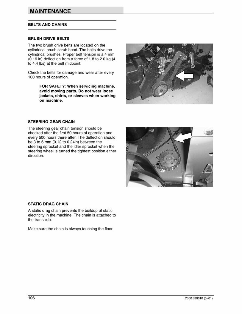
MAINTENANCE
7300 330610 (5−01)106
BELTS AND CHAINS
BRUSH DRIVE BELTS
The two brush drive belts are located on thecylindrical brush scrub head. The belts drive thecylindrical brushes. Proper belt tension is a 4 mm(0.16 in) deflection from a force of 1.8 to 2.0 kg (4to 4.4 lbs) at the belt midpoint.
Check the belts for damage and wear after every100 hours of operation.
FOR SAFETY: When servicing machine,avoid moving parts. Do not wear loosejackets, shirts, or sleeves when workingon machine.
STEERING GEAR CHAIN
The steering gear chain tension should bechecked after the first 50 hours of operation andevery 500 hours there after. The deflection shouldbe 3 to 6 mm (0.12 to 0.24in) between thesteering sprocket and the idler sprocket when thesteering wheel is turned the tightest position eitherdirection.
STATIC DRAG CHAIN
A static drag chain prevents the buildup of staticelectricity in the machine. The chain is attached tothe transaxle.
Make sure the chain is always touching the floor.

MAINTENANCE
1077300 330610 (5−01)
SKIRTS AND SEALS
SCRUB HEAD FLOOR SKIRTS
The skirts are located in front and rear of the discbrush scrub heads. Check the skirts for damageand wear every 50 hours of operation.
The skirts should clear the floor by 0 to 6 mm (0to 0.24in) when the scrub brushes are new, andthe scrub head is down.
FRONT COVER SEALS
The front cover seals are located around the edgeof the opening between the front cover, operatorcompartment, and solution recovery tank.
Check the seals for wear or damage every 100hours of operation.

MAINTENANCE
7300 330610 (6−00)108
SOLUTION TANK COVER SEAL
The solution tank cover seal is located under thesolution tank cover.
Check the seal for wear or damage every 100hours of operation.
RECOVERY TANK COVER SEAL
The recovery tank cover seal is located under therecovery tank cover.
Check the seal for wear or damage every 100hours of operation.

MAINTENANCE
1097300 330610 (5−01)
BRAKES AND TIRES
BRAKES
The foot brake and the parking brake operate thelinkage that controls the brakes on the rearwheels.
The foot pedal should not travel more than 25 mm(1in) to engage the brake. Check the brakeadjustment after every 100 hours of operation.
Park the machine on a level surface. Turn themachine power off, and block the machine tires.
Loosen the adjustment nuts. Adjust the brakecable with one nut and lock in place with the othernut.
Adjust the brake cable so that the brake pedaltravels no more than 25 mm (1in) to fully engagethe brakes. Readjust the brake cable if necessary.
Remove the blocks from the machine tires.
TIRES
All the machine tires are solid. Check the tires forwear every 100 hours of operations.
FRONT WHEEL
Torque the front wheel nuts twice in the patternshown to 122 to 155 Nm (87−111 ft. lbs) after thefirst 50 hours of operation, and every 500 hours ofoperation.
2
3
4
1
5

MAINTENANCE
7300 330610 (7−00)110
PUSHING, TOWING, AND TRANSPORTINGTHE MACHINE
PUSHING OR TOWING THE MACHINE
If the machine becomes disabled, it can bepushed from the front or rear, but only tow it fromthe front.
Only push or tow the machine for a very shortdistance and do not exceed 3.2 kph (2mph). It isNOT intended to be pushed or towed for a longdistance or at a high speed.
ATTENTION! Do not push or towmachine for a long distance or damagemay occur to the propelling system.
TRANSPORTING THE MACHINE
1. Position the front of the machine at theloading edge of the truck or trailer.
FOR SAFETY: Use truck or trailer thatwill support the weight of the machine.
NOTE: Empty the solution and recovery tanksbefore transporting the machine.
2. If the loading surface is not horizontal or ishigher than 380 mm (15in) from the ground,use a winch to load machine.
If the loading surface is horizontal AND is380 mm (15in) or less from the ground, themachine may be driven onto the truck ortrailer.
3. To winch the machine onto the truck ortrailer, attach the winching chains to the fronttie down locations. The front tie-downlocations are on the front sides of themachine. Make sure the machine iscentered.
FOR SAFETY: When loading machineonto truck or trailer, use winch. Do notdrive the machine onto the truck ortrailer unless the loading surface ishorizontal AND is 380 mm (15in) or lessfrom the ground.

MAINTENANCE
1117300 330610 (7−00)
4. Position the machine onto the truck or traileras far as possible. If the machine starts toveer off the centerline of the truck or trailer,stop and turn the steering wheel to centerthe machine.
5. Set the parking brake and block the machinetires. Tie down the machine to the truck ortrailer before transporting.
The front tie-down locations are on the frontsides of the machine.
The rear tie-down locations are on the rearsides of the machine.
6. If the loading surface is not horizontal or ishigher than 380 mm (15in) from the ground,use a winch to unload machine.
If the loading surface is horizontal AND is380 mm (15in) or less from the ground, themachine may be driven off the truck ortrailer.
FOR SAFETY: When unloading machineoff truck or trailer, use winch. Do notdrive the machine off the truck or trailerunless the loading surface is horizontalAND 380 mm (15in) or less from theground.

MAINTENANCE
7300 330610 (7−00)112
MACHINE JACKING
Empty the solution and recovery tanks beforejacking the machine. You can jack up the machinefor service at the designated locations. Use ahoist or jack that will support the weight of themachine. Always stop the machine on a flat, levelsurface and block the tires before jacking up themachine.
The front jacking location is in the center of thefront bumper
The rear jacking locations are located on the rearbumper, behind the rear tires.
Always stop the machine on a flat level surfaceand block the machine tires before jacking up themachine.
FOR SAFETY: When servicing machine,block machine tires before jackingmachine up.
FOR SAFETY: When servicing machine,jack machine up at designated locationsonly. Block machine up with jackstands.

MAINTENANCE
1137300 330610 (6−09)
STORAGE INFORMATION
The following steps should be taken when storingthe machine for extended periods of time.
1. Drain and clean the solution and recoverytanks.
ES machines: Run clean water through thesolution system and the ES solution pump.
2. Raise the rear squeegee and the scrubhead.
3. Park the machine in a cool, dry area.
4. Remove the batteries, or charge them afterevery three months.
NOTE: Storing or transporting machines equippedwith the ES or the FaST system in freezingtemperatures requires special procedures.Consult a TENNANT representative for moreinformation.
FREEZE PROTECTION (MACHINES WITHOUTOPTIONAL ec−H2O SYSTEM)
1. Drain the solution tank and recovery tank ofall water.
2. Pour 6 gallons (3.8 liters) of PropyleneGlycol Based / Recreational Vehicle (RV)Antifreeze into the solution tank at fullstrength. Do not dilute.
3. Turn the machine power on and operate thesolution flow system. Turn the machine offwhen the antifreeze appears at the scrubhead.
If the machine is equipped power wandoption, operate the the wand for a fewseconds to protect the pump.

MAINTENANCE
7300 330610 (6−09)114
FREEZE PROTECTING THE ec−H2O SYSTEM
1. Completely empty the solution tank andrecovery tank.
2. Start the machine and run all remainingsolution from the solution system. Run thesolution system until solution no longerappears at the scrub head.
3. Remove the siphon hose from the retainer.
4. Disconnect the ec−H2O system intake hosefrom the solution supply hose.
5. Connect the siphon hose to the ec−H2Osystem intake hose and place the siphonhose into container containing 2 gallons (7.6liters) of Propylene Glycol Based /Recreational Vehicle (RV) Antifreeze.
6. Press and release the flush switch on theec−H2O module to cycle the RV antifreezethrough ec−H2O system. When theantifreeze appears at the scrub head, pressthe switch again to turn off the module.
7. Disconnect the siphon hose from theec−H2O system intake hose.
8. Reconnect ec−H20 intake hose to thesolution supply hose.

MAINTENANCE
1157300 330610 (6−09)
9. Reconnect the siphon hose to the retainerand neatly coil the hose for storage.
IMPORTANT: Before operating the machine, theantifreeze must be flushed from the module. SeeFLUSHING ANTIFREEZE FROM ec−H2OMODULE section of this manual.
10.If machine is equipped power wand option,operate the the wand for a few seconds toprotect the pump.
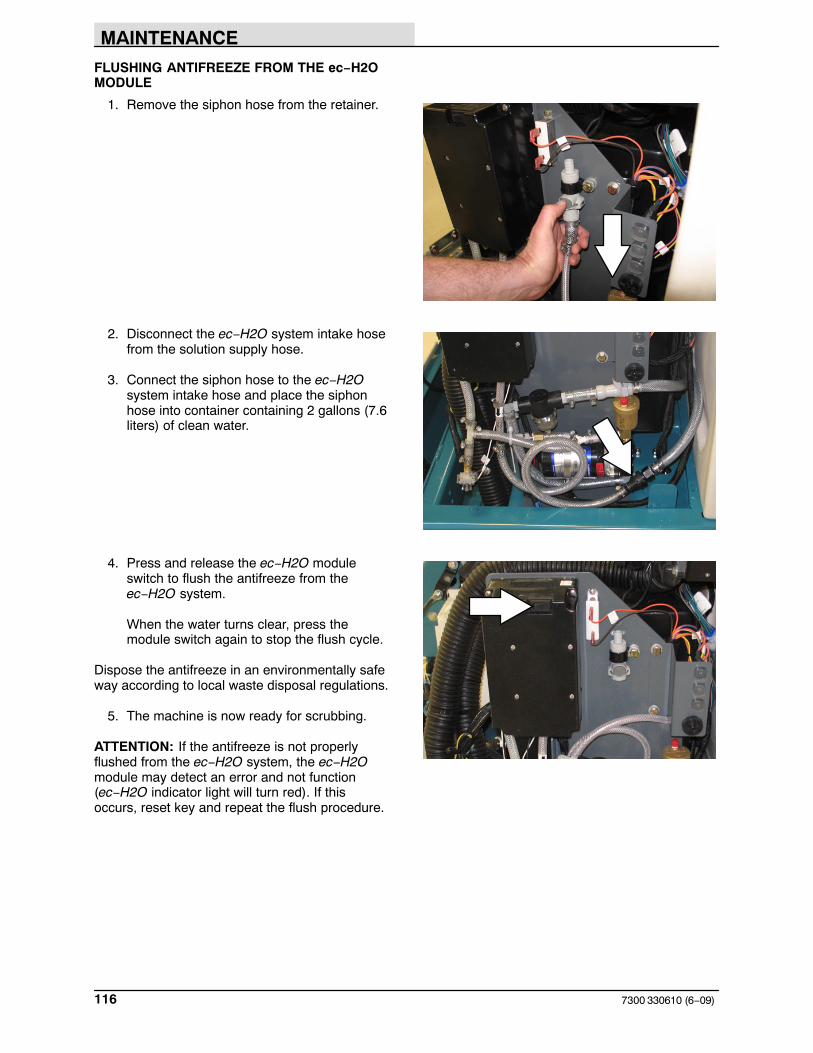
MAINTENANCE
7300 330610 (6−09)116
FLUSHING ANTIFREEZE FROM THE ec−H2OMODULE
1. Remove the siphon hose from the retainer.
2. Disconnect the ec−H2O system intake hosefrom the solution supply hose.
3. Connect the siphon hose to the ec−H2Osystem intake hose and place the siphonhose into container containing 2 gallons (7.6liters) of clean water.
4. Press and release the ec−H2O moduleswitch to flush the antifreeze from theec−H2O system.
When the water turns clear, press themodule switch again to stop the flush cycle.
Dispose the antifreeze in an environmentally safeway according to local waste disposal regulations.
5. The machine is now ready for scrubbing.
ATTENTION: If the antifreeze is not properlyflushed from the ec−H2O system, the ec−H2Omodule may detect an error and not function(ec−H2O indicator light will turn red). If thisoccurs, reset key and repeat the flush procedure.

SPECIFICATIONS
1177300 330610 (2−10)
SPECIFICATIONS
GENERAL MACHINE DIMENSIONS/CAPACITIES
Item Dimension/capacity
Length 2134 mm (84 in)
Width, frame 1143 mm (45 in)
Width, frame with right hand side brush (option) 1282 mm (50.5 in)
Width, frame with dual side brush (option) 1422 mm (56 in)
Width with rear squeegee 1300 mm (51 in)
Width with MaxPro 1200 scrub head option 1510 mm (53 in)
Height 1450 mm (57 in)
Height with overhead guard option 2070 mm (81.5 in)
Disc brush diameter for Max Pro 1000 510 mm (20 in)
Disc brush diameter for Max Pro 1200 406 mm (16 in)
Cylindrical brush diameter 229 mm (9 in)
Cylindrical brush length for Max Pro 1000 978 mm (38.5 in)
Cylindrical brush length for Max Pro 1200 1180 mm (46.5 in)
Rear Squeegee width for Max Pro 1000 1300 mm (51 in)
Rear Squeegee width for Max Pro 1200 1510 mm (59.5 in)
Scrubbing path width for Max Pro 1000 1020 mm (40 in)
Scrubbing path width for Max Pro 1200 1220 mm (48 in)
Solution tank capacity 216 L (57 gal)
Recovery tank capacity 216 L (57 gal)
Tank capacity with ES option 340 L (90 gal)
Propelling gear box 90 wt. gear lubricant capacity 2.7 L (2.7 qt)
GVWR 2060 kg (4580 lb)
Vibration level at steering wheel does not exceed 2.5 m/s2
Vibration level at operator seat does not exceed 0.5 m/s2
FaST SYSTEM
Item Measure
Solution pump 36 Volt DC, 5A, 5.7 LPM (1.5 GPM) open flow, 45 psi bypass setting
Low solution flow rate 2.08 LPM (0.55 GPM)
High solution flow rate 4.16 LPM (1.1 GPM)
Detergent pump 36 Volt DC
Low concentrate flow rate 2.14 CC/Minute (0.07 Liquid Ounces/Minute)
High concentrate flow rate 4.28 CC/Minute (0.14 Liquid Ounces/Minute)
Air pump 36 Volt DC, 0.6 Maximum Amp draw
Air pump flow rate 8.7 LPM (0.3 CFM) open flow

SPECIFICATIONS
7300 330610 (2−04)118
GENERAL MACHINE PERFORMANCE
Item Measure
Maximum forward speed 7.2 km/h (4.5 mph)
Maximum reverse speed 4.8 km/h (3mph)
Minimum turning radius, left 3620 mm (142.5 in)
Minimum turning radius, right 3680 mm (145 in)
Minimum isle turn width 2410 mm (95 in)
Maximum rated climb and descent angle with full tanks 6�
Maximum rated climb and descent angle with empty tanks 8�
POWER TYPE
Type Quantity Volts Ah Rating Weight
Batteries, Dry 1 36 500 @ 6 hr rate 617 kg (1370 lb)
1 36 750 @ 6 hr rate 893 kg (1984 lb)
Batteries, Sealed 1 36 600 @ 6 hr rate 810 kg (1800 lb)
Batteries, Wet 1 36 380 @ 6 hr rate 436 kg (960 lb)
1 36 500 @ 6 hr rate 617 kg (1370 lb)
1 36 750 @ 6 hr rate 893 kg (1984 lb)
Type Use VDC Kw (hp)
Electric Motors Scrub brush 36 0.75 (1)
Heavy Duty scrub brush 36 1.12 (1.5)
Vacuum fan 36 0.63 (0.85)
Propelling 36 3.4 (4.6)
Type VDC amp Hz Phase VAC
Chargers 36 75 60 1 208−240−480
36 75 60 3 208−240−480
36 120 60 1 208−240−480
36 120 60 3 208−240−480
36 150 60 1 208−240−480
36 150 60 3 208−240−480
36 93 60 1 208−240−480
36 93 60 3 208−240−480

SPECIFICATIONS
1197300 330610 (2−10)
STEERING
Type Power source Emergency steering
Front wheel controlled, universal joint to gear andchain
Manual Manual
Front wheel, hydraulic cylinder and rotary valvecontrolled
Hydraulic (Option) Manual
HYDRAULIC SYSTEM
System Capacity Fluid Type
Hydraulic reservoir (Power Steering Option) 1.9L (0.5 gal) ISO Grade 32 − below 7� C (45� F)
Hydraulic total (Power Steering Option) 2.3L (0.6 gal)
BRAKING SYSTEM
Type Operation
Service brakes Mechanical drum brakes (2), one per rear wheel, cable actuated
Parking brake Utilizes service brakes, cable actuated
TIRES
Location Type Size
Front (1) Solid 413 X 152 mm (16.25 x 6 in)
Rear (2) Solid 406 X 127 mm (16 x 5 in)
ec−H20 SYSTEM
Item Measure
Solution pump 36 Volt DC, 5A, 5.7 LPM (1.5 GPM) open flow, 45 psi bypass setting
Solution flow rate 1.67 LPM (0.44 GPM) − Low (optional)*
2.35 LPM (0.62 GPM) − Low (standard)
3.18 LPM (0.84 GPM) − Low (optional)*
3.80 LPM (1.00 GPM) − High (standard)
*If the optional solution flow rates are required,contact an Authorized Service Center.
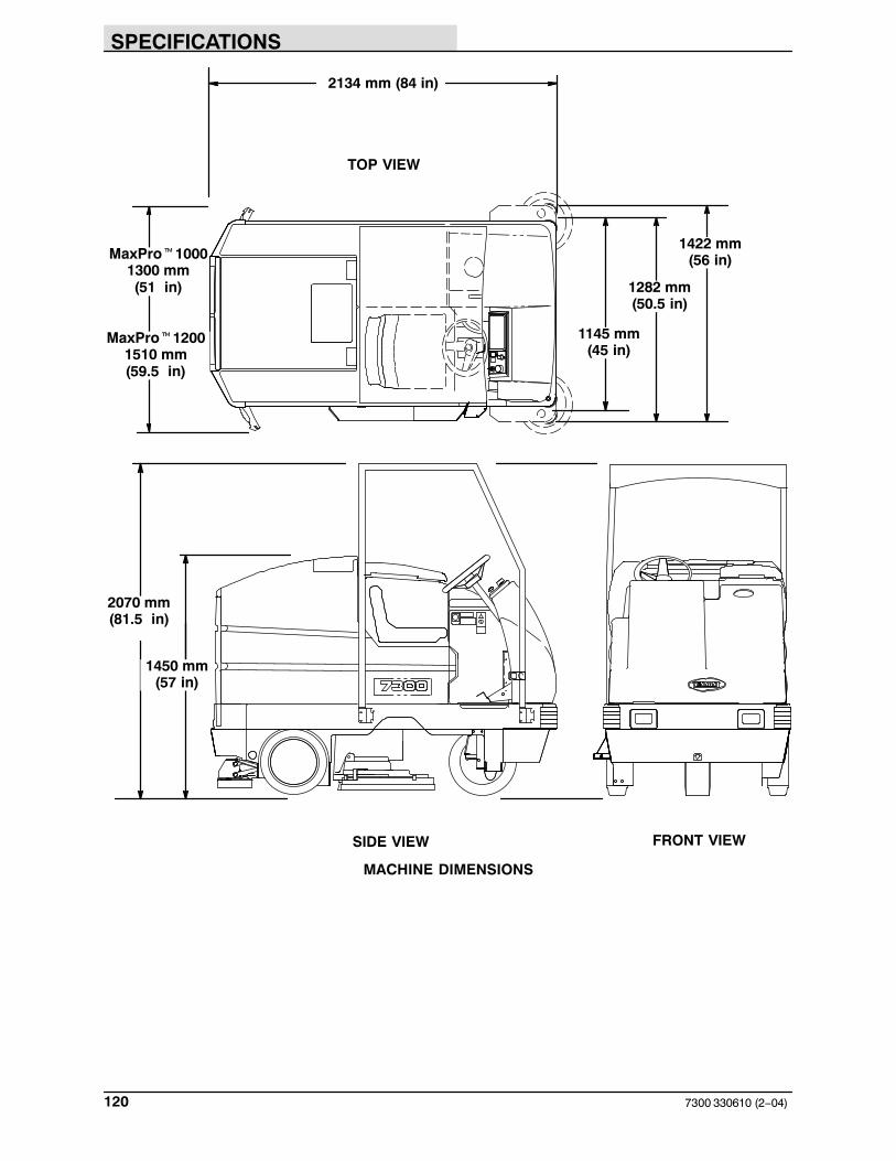
SPECIFICATIONS
7300 330610 (2−04)120
2070 mm(81.5 in)
2134 mm (84 in)
MaxPro�10001300 mm(51 in)
1450 mm(57 in)
TOP VIEW
SIDE VIEW FRONT VIEW
MaxPro�12001510 mm(59.5 in)
1145 mm(45 in)
1282 mm(50.5 in)
1422 mm(56 in)
MACHINE DIMENSIONS

INDEX
1217300 330610 (6−09)
A
Adjusting rear squeegee blade deflection, 100
Adjusting the side squeegee, 102
Adjustments, Service brakes, 108
Aisle turn, 117
Ajustments, Steering gear chain, 105
B
Batteries, 77–80Charger specifications, 117Charging, 78–80Discharge indicator, 17Maintenance, 77Specifications, 117
Battery, Fluid level, 36, 57
Battery discharge indicator, 17
BearingsFront wheel support, 72Rear wheel, 74
Belts, Brush drive, 105
Belts and chains, 105
Brake pedal, 10
Brakes, 36, 57, 108
Brakes and Tires, 108
Braking system, Specifications, 118
Brush drive belts, 105
Brush pressure adjustment, scrubbing, 19
Brushesinformation, recommendations, 43Maintenance, 36, 57Scrubbing, 43Side sweeping brush replacement, 92
Button, Horn, 12
C
Capacities, 116
Chain, Steering gear, 74
ChainsStatic drag, 105Steering gear, 105
Changing message display language, 16
Circuit breakers, 28
Control panel, 19Battery discharge indicator, 17Changing message display language, 16detergent pump switch (option), 24Display clock, 18display clock setting & adjusting, 18Edge scrub switch, 21ES switch, 21functions, 15Hourmeter, 17maintenance mode, 24, 25, 26Rear squeegee switch, 22Recovery tank full indicator, 21Self-diagnostics, 80Side brush switch (option), 23Super Scrub switch, 20
Controls, 9Battery discharge indicator, 17Brake pedal, 10Circuit breakers, 28Directional pedal, 10ec−H20 switch (option), 15Edge scrub, 21ES switch, 21FaST switch (option), 14Horn button, 12Hourmeter, 17On-off key switch, 12Operating lights switch, 13Parking brake pedal, 10Power kill switch, 13Power wand switch, 13Rear squeegee switch, 22Recovery tank full indicator, 21Scrub switch, 19Side brush (Option), 23Side brush adjustment knob (Option), 32Solution flow lever, 14Steering wheel, 11Steering wheel column tilt lever, 14
Cylindrical brushesChecking and adjusting brush pattern, 87–89Replacing brushes, 90
D
Debris tray, Clean, 36, 57
Detergent pump switch (option), 24
Dimensions, 116
Directional pedal, 10
Display clock, 18setting & adjusting, 18
Double scrubbing, 50
Draining and cleaning the tanks, 51–53

INDEX
7300 330610 (6−09)122
E
ec-H20 module flush procedure, 97
ec-H20 Scrubbing System, Indicator LightCodes, 46
ec-H20 Scrubbing System Indicator LightCodes , 46
ec-H20 switch, 15
ec-H20 System, 35
Edge scrub switch, 21
Electric motors, 82, 117
ElectricalBatteries, 77–80Charging batteries, 78–80Circuit breakers, 28
Electrical system, fuses, 27
Electronics, Propelling circuit, 82
ESAuto-fill, 42Clean tanks, 36, 57Detergent level, 36, 57Filling the tanks, 40–42
ES switch, 21
F
FaST, System, 95
FaST pak agent, Installing, 37–39
FaST pak agent installation, 37–39
FaST Supply Hose Connector, 95
FaST switch, 14
FaST System, 34, 95FaST supply hose connector, 95
FaST system, Priming the FaST solution system,38
FaST System Air Pump Filter, 95, 96
FaST System Filter Screen, 95
Filling the tanks, 40–42
FilterFaST System Air Pump Filter, 95, 96FaST System Filter Screen, 95Vacuum fan inlet, 36, 57
Flush antifreeze from ec-H20 module, 115
Freeze protection, 112
Freeze protection, ec-H20 system, 113
Front cover seals, 106
Front wheelSupport bearing, 72Torque, 108
Front wheel support bearing, 72
Fuses, 27
H
Horn button, 12
HosesRecovery tank drain, 30Solution tank drain (option), 30
Hourmeter, 17
How the machine works, 33
Hydraulics, Fluid level, 36, 57
Hydraulics (option), 75Hydraulic fluid, 76Hydraulic fluid reservoir, 75Hydraulic hoses, 76Specifications, 118
I
Indicator Light Codes, ec-H20 ScrubbingSystem, 46
IndicatorsRecovery tank full, 21Scrub brush pressure, 19
J
Jack points, 111
Jacking, 111
K
Knobs, Side brush adjustment (Option), 32
L
Latches, 30
Leveling the rear squeegee, 99
LeversSolution flow, 14Steering wheel column tilt, 14

INDEX
1237300 330610 (6−09)
Lubrication, 72Front wheel support bearing, 72Propelling gearbox, 72Rear wheel bearings, 74Scrub head drag link arms, 73Steering gear chain, 74
M
Machine, Jacking, 111
Machine components, 6
Machine dimensions, 119
Machine tie down locations, 110
Maintenance, 70–94Checking and adjusting brush pattern, 87–89Cylindrical brushes, 87Disk brushes, 84–89Intervals, 70Recommended, 5Replacing cylindrical brushes, 90Replacing disk brushes, 84Scrub brushes, 84–89
Maintenance chart, 70
Maintenance modedefinition, 24disabling, 26resetting timers, 25
Motors, Electric, 82, 117
O
On‐off key switch, 12
Operating lights switch, 13
Operation, 5–54
Operation on inclines, 58
Operationscontrol panel functions, 15stop scrubbing, 50–52
Operator Responsibility, 5
Operator seat, 31suspension (option), 31
Options, 58–66ES switch, 21Positive solution control drain, 30Power wand, 62–69Power wand switch, 13Side brush adjustment knob (Option), 32Side brush switch, 23Side sweeping brush(es), 92Solution tank drain hose, 30Vacuum wand, 58–62
P
Parking brake pedal, 10
Pedal, Directional, 10
PedalsBrake, 10Parking brake, 10
Positive solution control drain, 30
Post‐operation checklist, 57
Power kill switch, 13
Power wand, 62–69
Power wand switch, 13
Pre‐operation checklist, 36
Propelling circuit, 82
Propelling gearbox, 72
Pushing machine, 109
Pushing or towing the machine, 109
Pushing, towing, and transporting machine, 109
R
Rated incline and descent, 117
Rear squeegee, 99Adjusting deflection, 100Leveling, 99
Rear squeegee assembly, Removal, 101
Rear squeegee blades, 102
Rear squeegee switch, 22
Rear wheel bearings, 74
Recoevery tank, Drain and clean, 36, 57
Recovery tank, 93Drain hose, 30Draining and cleaning, 51–53Positive solution control drain, 30Tank full indicator, 21
Recovery tank cover seal, 107
Recovery tank drain hose, 30
Replacing disk brushes, 84
Replacing rear squeegee blades, 102
Rotating rear squeegee blades, 102
INDEX
7300 330610 (6−09)124
S
SafetyLabels, 4Precautions, 3
Screen, FaST System Filter Screen, 95
Scrub brush pressure adjustment, 19
Scrub brushes, 84–89Adjusting cylindrical brush pattern, 87–89Brush pressure, 19Checking cylindrical brush pattern, 87–89Cylindrical brushes, 87Disk brushes, 84Replacing cylindrical brushes, 90Replacing disk brushes, 84
Scrub functions, stop scrubbing, 50–52
Scrub head, 83–89Adjustments, 83Drag link arms, 73Floor skirts, 106Gas spring, 83
Scrub head adjustments, 83
Scrub head drag link arms, 73
Scrub head floor skirts, 106
Scrub head gas spring, 83
Scrub switch, 19
Scrubbing, 45Double, 50
Scrubbing brushes, 43
Scrubbing information, 43
Scrubbing pads, 44
Seals, Tank Cover, 36, 57
Seat, suspension, (option), 31
Self‐diagnostics, 80
Service records, 36, 57
Side brush adjustment knob (Option), 32
Side brush switch (option), 23
Side brush(es) (Option), replacement &adjustment, 92
Side squeegee, Adjusting, 102
Side squeegee blades, 104
Side squeegees, 102
Side sweeping brush(es), information, 92
Skirts, Scrub head floor, 106
Skirts and seals, 106–112Front cover, 106Recovery tank cover seal, 107Solution tank cover seal, 107
SolutionFilling the tanks, 40–42Flow lever, 14System, 93Tank drain hose (option), 30
Solution flow lever, 14
Solution System, 93
Solution system, Solution valve, 93
Solution Tank, 94
Solution tankDrain hose (option), 30Draining and cleaning, 51–53Filling, 40–42Positive solution control drain, 30
Solution tank cover seal, 107
Solution tank drain hose (option), 30
Solution valve, 93
Specifications, 116–118Braking system, 118Chargers, 117ec−H20 System, 118ec−H20 system, 118Electric motors, 117FaST System, 116Hydraulics, 118Machine capacities, 116Machine dimensions, 116Machine performance, 117Power type, 117Steering, 118Tires, 118
Squeegee, 99–102Adjustment, 36, 57Blades, 102
Squeegee blades, 102Rear, 102Replacing or rotating rear, 102Side, 104
Squeegees, Side, 102
Staring the machine, 39
Static drag chain, 105
Steering, 36, 57Specifications, 118
Steering gear chain, 74, 105

INDEX
1257300 330610 (6−09)
Steering wheel, 11
Steering wheel column tilt lever, 14
Stop Scrubbing, 50
Stop the machine, 56
Storage information, 112
Super Scrub switch, 19, 20
Sweeping brushes (Option)side brush information, 92side brush(es) replacement & adjustment, 92
Sweeping information, 43
Switch, detergent pump (option), 24
Switchesec−H20, 15Edge scrub, 21ES, 21FaST, 14On-off key, 12Operating lights, 13Power kill, 13Power wand, 13Rear squeegee, 22Scrub, 19Side brush (option), 23Super Scrub, 20
Symbol definitions, 7, 8
T
TanksRecovery, 93Solution, 94
Tie down locations, 110
Tires, 108–109Specifications, 118
Towing machine, 109
Transporting machine, 109
Transporting the machine, 109
Troubleshooting, 68
V
Vacuum wand, 58–62
W
Wheel nuts, Torque, 108