70B F2012 NEC-AAC ROP ballot - NFPA National Standards Institute,Inc., 25 West 43rd Street, 4th...
89
National Fire Protection Association 1 Batterymarch Park, Quincy, MA 02169-7471 Phone: 617-770-3000 • Fax: 617-770-0700 • www.nfpa.org M E M O R A N D U M TO: NEC Technical Correlating Committee FROM: Kimberly Shea DATE: October 31, 2011 SUBJECT: NFPA 70B ROP TCC Letter Ballot (F2012) In accordance with the NFPA Regulations Governing Committee Projects, attached is the Letter Ballot on the Report on Comments (ROC) for the 2013 Edition of NFPA 70B. Also attached is a copy of the Comments containing the final ballot results of the Technical Committee on Electrical Equipment Maintenance. Please note the ballot has two parts: Part 1 is a Letter Ballot on the Technical Correlating Committee Amendments to the ROC (TCC Notes), and not on the Comments themselves. Reasons must accompany “Negative” and “Abstaining” votes. Part 2 is an Informational Letter Ballot Authorizing the Release of the ROC. Negative votes are limited to subjects within the purview of the TCC. Opposition on a strictly technical basis is not sufficient grounds for substantiating a negative vote. If you have correlation issues please identify and describe your concerns in the area of the ballot form for identification of correlation issues. Please complete and return your ballot as soon as possible but no later than Thursday, November 3, 2011. As noted on the ballot form, please return the ballot via e-mail to [email protected] or via fax to 617 984-7070. You may also mail your ballot to the attention of Kim Shea at NFPA, 1 Batterymarch Park, Quincy, MA 02169. The return of ballots is required by the Regulations Governing Committee Projects. As usual, nonvoting members (for example, the nonvoting technical committee chairs) need not return ballots. Attachments: Ballot Form NFPA 70B Comments
-
Upload
nguyenthuy -
Category
Documents
-
view
220 -
download
2
Transcript of 70B F2012 NEC-AAC ROP ballot - NFPA National Standards Institute,Inc., 25 West 43rd Street, 4th...
National Fire Protection Association 1 Batterymarch Park, Quincy, MA 02169-7471 Phone: 617-770-3000 • Fax: 617-770-0700 • www.nfpa.org
M E M O R A N D U M TO: NEC Technical Correlating Committee FROM: Kimberly Shea DATE: October 31, 2011 SUBJECT: NFPA 70B ROP TCC Letter Ballot (F2012) In accordance with the NFPA Regulations Governing Committee Projects, attached is the Letter Ballot on the Report on Comments (ROC) for the 2013 Edition of NFPA 70B. Also attached is a copy of the Comments containing the final ballot results of the Technical Committee on Electrical Equipment Maintenance. Please note the ballot has two parts: Part 1 is a Letter Ballot on the Technical Correlating Committee Amendments to the ROC (TCC Notes), and not on the Comments themselves. Reasons must accompany “Negative” and “Abstaining” votes. Part 2 is an Informational Letter Ballot Authorizing the Release of the ROC. Negative votes are limited to subjects within the purview of the TCC. Opposition on a strictly technical basis is not sufficient grounds for substantiating a negative vote. If you have correlation issues please identify and describe your concerns in the area of the ballot form for identification of correlation issues. Please complete and return your ballot as soon as possible but no later than Thursday, November 3, 2011. As noted on the ballot form, please return the ballot via e-mail to [email protected] or via fax to 617 984-7070. You may also mail your ballot to the attention of Kim Shea at NFPA, 1 Batterymarch Park, Quincy, MA 02169. The return of ballots is required by the Regulations Governing Committee Projects. As usual, nonvoting members (for example, the nonvoting technical committee chairs) need not return ballots. Attachments: Ballot Form NFPA 70B Comments

Report on Proposals – November 2012 NFPA 70B_______________________________________________________________________________________________70B-1 Log #CP1 EEM-AAA
_______________________________________________________________________________________________Technical Committee on Electrical Equipment Maintenance,
Review entire document to: 1) Update any extracted material by preparing separate proposals todo so, and 2) review and update references to other organizations documents, by preparing proposal(s) as required.
To conform to the NFPA Regulations Governing Committee Projects.
The committee actions on 70B-1a (Log #CP10), 70B-84 (Log #CP12), and 70B-85 (Log#CP13) addresses the requested and required action.
Affirmative: 141 Wyman, B.
1Printed on 10/31/2011

Report on Proposals – November 2012 NFPA 70B_______________________________________________________________________________________________70B-1a Log #CP10 EEM-AAA
_______________________________________________________________________________________________Technical Committee on Electrical Equipment Maintenance,
Revise the references in 2.2 and 2.3 as follows:The documents or portions thereof listed in this chapter are referenced within this
recommendedpractice and should be considered part of the recommendations of this document.
®, 2008 2011 edition.®, 2009 2012 edition.
NFPA 110, 2010 edition.NFPA 496, 2008 edition.
®, 2010 edition.
American National Standards Institute,Inc., 25 West 43rd Street, 4th Floor, New York, NY10036.ANSI/EASA AR100, , 2001.
American Society for Testing and Materials, 100 Barr Harbor Drive, West Conshohocken,PA19428-2959.ASTM D 92-05a(2010),ASTM D 445-11a,
2009.ASTM D 664 - 11, 2001.ASTM D 877-02 (2007),
, 2002.ASTM D 923-07, , 1997.ASTM D 924 -08,
, 2003.ASTM D 971-99a (2004), ,1999a.ASTM D 974-02, , 2002.ASTM D 1298-99(2005),
2005.ASTM D 1500-07, , 2002.ASTM D 1524-94 (1999),
, 1994 (1999).ASTM D 1533-00(2005),2005.ASTM D 1816-04,
1997.ASTM D 2129-05(2010),2005.ASTM D 2285-99,
, 1999.ASTM D 2472-00 (2006), , 2000.ASTM D 3284-05 (2011),
1999.ASTM D 3612-02 (2009),
, 2002.2.3.2 . Electrical Apparatus Service Association, 1331 Baur Blvd, St. Louis, MO 63132.ANSI/EASA AR100, , 2010.
Institute of Electrical and Electronics Engineers, Three Park Avenue, 17th Floor, New York,NY 10016-5997.ANSI/IEEE 43 (R 1991), , 2000.
2Printed on 10/31/2011

Report on Proposals – November 2012 NFPA 70BANSI/IEEE 80, , 1986 2000.IEEE 81,1983.ANSI/IEEE 95,
, 2002.ANSI/IEEE 141, (Red Book), 1993.ANSI/IEEE 142, (Green Book),1991 2007.ANSI/IEEE 241, (Gray Book), 1990.ANSI/IEEE 242,(Buff Book), 1986 (reaff. 1991) 2001.ANSI/IEEE 399, (Brown Book), 1990.ANSI/IEEE 400,
, 1991 2001.IEEE 400.1,
2007.IEEE 400.2, 2004.IEEE 400.3, 2006.ANSI/IEEE 446,
1995.ANSI/IEEE 450,
2002 2010.ANSI/IEEE 493, (GoldBook), 1990 2007.ANSI/IEEE 519, , 1992.IEEE 637, 1985.ANSI/IEEE 1100, (Emerald Book),1992 2005.IEEE 1106,
1995 2005.IEEE 1125, , 1993 (R 2000).IEEE 1159, , 1995 2009.IEEE 1188,
2005.ANSI C2, 2007.ANSI/IEEE C37.13, , 1990 2008.IEEE C37.20.1, , 2002.IEEE C37.23, , 1987 (reaff. 1991) 2003.IEEE C37.122.1, , 1993 (R 2002).ANSI/IEEE C57.104, , 1991 2008.ANSI/IEEE C57.106, 2002 2006.ANSI/IEEE C57.110,
, 1986 (reaff. 1993) 2008.ANSI/IEEE C57.111, 1989(R1995).ANSI/IEEE C57.121,1998.
Information Technology Industry Council, 1250 Eye Street NW, Suite 200,Washington, DC20005. 202-737-8880. http://www.itic.org.
2000.National Electrical Manufacturers
Association, 1300 North 17th Street, Suite 1847, Rosslyn, VA22209.NEMA AB 1-99, , 1999(Equivalent to the current edition of UL 489).ANSI/NEMA AB 4,
, 2009.
3Printed on 10/31/2011
Report on Proposals – November 2012 NFPA 70BANSI/NEMA C84.1, 1995 2006.NEMA MG 1, , 2003 2009 (R 2010).ANSI/NEMA PB 2.1,
2007.NEMA SG 6, , 2000.NEMA WD 6, , 1997 2002 (R2008).NEMA2005 2006.
InterNational Electrical Testing Association, P.O. Box 687, Morrison, CO 80465.ANSI/NETA ATS-2009, ,ATS-2003.ANSI/NETA MTS-2011,MTS-2001.
Underwriters Laboratories Inc., 333 Pfingsten Road, Northbrook, IL 60062-2096.ANSI/UL 489, , Tenth edition,2002,(R 2006) Revised 2011.ANSI/UL 943, , 2006, (R 2008) Revised 2010.UL 1436, , 4th edition, 1998, (R 2004) 2004.
U.S. Government Printing Office,Washington, DC 20402-9328.Title 29, Code of Federal Regulations, Part 1910.Title 29, Code of Federal Regulations, Part 1926.Title 29, Code of Federal Regulations, Part 1910.94(a), “Occupational Health and Environmental Control—Ventilation.”Title 29, Code of Federal Regulations, Part 1910.146, “Permit-Required Confined Spaces.”Title 29, Code of Federal Regulations, Part 1910.242(b), “Hand and Portable Powered Tools and Other Hand HeldEquipment.”Title 29, Code of Federal Regulations, Part 1910.269, “Electric Power Generation, Transmission, and Distribution,”Paragraph (e), Enclosed Spaces.Title 29, Code of Federal Regulations, Parts 1910.331 through 1910.335, “Safety Related Work Practices.”Title 40, Code of Federal Regulations, Part 761, “Protection of Environment — Polychlorinated Biphenyls (PCBs)Manufacturing, Processing, Distribution in Commerce, and Use Prohibitions.”TM 5-694,
2006.TM 5-698-1,
, 2003.
, 11th edition, Merriam-Webster, Inc., Springfield, MA, 2003.ABB Power T & D Company, Inc.,
.®, 2008 2011 edition
The committee directs NFPA staff to revise document titles across the entire document to conform with the titles inproposal.
Updated references to reflect current editions and titles.
The committee intends to check the references again at the comment stage.
Affirmative: 141 Wyman, B.
4Printed on 10/31/2011

Report on Proposals – November 2012 NFPA 70B_______________________________________________________________________________________________70B-2 Log #37 EEM-AAA
_______________________________________________________________________________________________John F. Bender, Underwriters Laboratories Inc.
Revise text as follows:2.3.7 UL Publications. Underwriters Laboratories Inc., 333 Pfingsten Road, Northbrook, IL 60062-2096.ANSI/UL 489, Molded-Case Circuit Breakers, Molded-Case Switches and Circuit Breaker Enclosures, Tenth edition,
2002, (R 2006) 2009.ANSI/UL 943, Standard for Ground-Fault Circuit Interrupters, 2006, (R 2008) Revised 2010.UL 1436, Outlet Circuit Testers and Similar Indicating Devices, 4th edition, 1998, (R 2004) 2004.
Add ANSI approval designation to ANSI/UL 943 and update referenced standards to most recentrevision.
Revise the text of the recommendation to read as follows:2.3.7 UL Publications. Underwriters Laboratories Inc., 333 Pfingsten Road, Northbrook, IL 60062-2096.ANSI/UL 489, Molded-Case Circuit Breakers, Molded-Case Switches and Circuit Breaker Enclosures, EleventhTenth
edition, 2002, (R 2006) 2009, (R 2011).ANSI/UL 943, Standard for Ground-Fault Circuit Interrupters, 2006, (R 2008) Revised (R 2010).UL 1436, Outlet Circuit Testers and Similar Indicating Devices, 4th edition, 1998, (R 2004) 2004.
The committee actions corrects the edition of ANSI/UL 489 and ANSI/UL 943.
Affirmative: 141 Wyman, B.
_______________________________________________________________________________________________70B-2a Log #CP11 EEM-AAA
_______________________________________________________________________________________________Technical Committee on Electrical Equipment Maintenance,
Add the following new definitions:3.3.1 Arc Flash Hazard. A dangerous condition associated with the possible release of energy caused by an electric arc.[70E, 2012]3.3.2 Arc Flash Hazard Analysis. A study investigating a worker’s potential exposure to arc-flash energy, conducted forthe purpose of injury prevention and the determination of safe work practices, arc flash protection boundary, and theappropriate levels of PPE. [70E, 2012]Renumber all subsequent definitions.
Definition extracted from NFPA 70E as basis for another proposal in chapter 9.6.
Affirmative: 141 Wyman, B.
5Printed on 10/31/2011

Report on Proposals – November 2012 NFPA 70B_______________________________________________________________________________________________70B-3 Log #35 EEM-AAA
_______________________________________________________________________________________________John F. Bender, Underwriters Laboratories Inc.
Revise text as follows:A device intended for the protection of personnel that functions to
deenergize a circuit or portion thereof within an established period of time when a current to ground exceeds the valuesestablished for a Class A device. Note: Class A Ground-Fault Circuit Interrupters trip when the current to ground has avalue in the range of 4 mA to 6 mA. For further information, see ANSI/UL 943,
. [70, 2008].Add ANSI approval designation to ANSI/UL 943.
The committee rejects this proposal because the extracted definition from the NEC does notinclude the ANSI designation.
Affirmative: 141 Wyman, B.
_______________________________________________________________________________________________70B-4 Log #1 EEM-AAA
_______________________________________________________________________________________________
Michael A. Anthony, University of MichiganAdd item (3) as shown below.
5.2 Essential Elements of an EPM Program.An EPM program should consist of the following essential elements:(1) Responsible and qualified personnel(2) Regularly scheduled inspection, testing and servicing of equipment
Regular, fixed interval testing is not necessarily risk-informed. Fixed interval testing, while easy todocument, schedule and verify does always produce the intended result. Fixed interval testing can be over-testing,resulting in reduced resources available for more critical systems – in addition to increasing the likelihood ofmaintenance induced accidents and errors. Fixed interval testing may also have the unintended effect of retardinginnovation in products by transferring the cost of the useful life of the product to the Owner rather than building it into theinherent life-cycle value of the product itself.Acceptance of this comment will create a link between Annex K and the main body of this document and will suggest
other ways to rationalize a preventive maintenance budget with the nature and condition of the system or occupancy.
The committee finds that the present clause is adequate as written because the currentlanguage generically covers utilizing these tools.
Affirmative: 141 Wyman, B.
6Printed on 10/31/2011

Report on Proposals – November 2012 NFPA 70B_______________________________________________________________________________________________70B-5 Log #2 EEM-AAA
_______________________________________________________________________________________________
Michael A. Anthony, University of MichiganAdd text as shown follows:
Effective electrical preventive maintenance begins with good design. In thedesign of new facilities, a conscious effort to ensure optimum maintainability is recommended. Dual circuits, tie circuits,auxiliary power sources, and drawout protective devices make it easier to schedule maintenance and to performmaintenance work with minimum interruption of production. Other effective design techniques include equipment roomsto provide environmental protection, grouping of equipment for more convenience and accessibility, grouping of loadclasses on a dedicated circuit and standardization of equipment and components.
Mixed load classes on medium voltage circuits are common in campus-style facilities. The conditionevolves over time because of the increased cost of running bulk distribution circuits to buildings of the same occupancytype. Over time then, library and classroom buildings are on the same supply circuit as high rise health care and publicsafety office buildings; parking structures on the same circuit as central chiller plants that provide mission critical power.To the extent possible, planners of campus medium voltage distribution systems should try to partition these loadclasses – if for no other reason than to prioritize a load shedding regime back at the distribution switchgear in the districtenergy plant. Grouping of load classes would manage the economic affect of forced outages which will indirectly affectthe manner in which restoration and maintenance objectives are achieved.
The committee rejects because the previous phrase is encompassing the concept.
Affirmative: 141 Wyman, B.
7Printed on 10/31/2011

Report on Proposals – November 2012 NFPA 70B_______________________________________________________________________________________________70B-6 Log #3 EEM-AAA
_______________________________________________________________________________________________
Michael A. Anthony, University of MichiganModify punctuation and add the words “and occupancies” as shown in underline below.
The following four basic steps should be taken in the planning and development of an EPM program. In theirsimplest form, they are as follows:(1) Compile a listing of all equipment and systems.(2) Determine which equipment, and systems are most critical and most important.
An electrical preventive maintenance program should be scaled to the risk to the occupancy. Manyadopting organizations have virtually no additional money to comply with 70B recommendations but are opting toprioritize and to allocate resources to where the risk is greatest and where the probability of reducing adverseconsequences is greatest. Some of the criteria that could be used by AHJ’s and insurance companies are:● Facility classification. A distinction should be made between general business occupancies and health care and
high-rise facilities. A preventive maintenance program for a college campus would be more robust in a place ofassembly than in an off-site book storage warehouse.● Permanent maintenance staff. A supervised installation may be more watchful of the conditions of maintenance and
supervision; would be most familiar with baseline data and incident logs, and IT&M sampling strategies.● Overall characteristics of the electrical system. The age of the system, availability of spare parts, and the nature of
its supply source; system redundancy.
The committee rejects because the concept recommended is already covered and there is nosubstantiation for deleting the words "and most important."
Affirmative: 141 Wyman, B.
_______________________________________________________________________________________________70B-7 Log #73 EEM-AAA
_______________________________________________________________________________________________Michael A. Anthony, University of Michigan / Rep. APPA.ORG - Leadership in Education - Association of
Education Facility ExecutivesAdd new text as shown below:
6.3.1.2 The team should review the entire plant or each of its operating segments in detail, considering each unit ofequipment as related to the entire operation and the effect of its loss on safety and production.6.3.1.2.x Each branch circuit and feeder should be visibly and permanently marked to distinguish whether or not the
end use equipment supplied from it is an emergency power load or a standby power load. The distinction may assistelectricians determine which circuits may be de-energized in emergency and/or or maintenance conditions.
Electricians are frequently reluctant to de-energize circuits for maintenance or load-sheddingoperations because they do not know enough about the end-use equipment. Identifying circuits according to priority --and making this identification a permanent part of the maintenance program -- may enable safer, and more economicalmaintenance.
The committee rejects because the NEC already addresses the minimum markingrequirements and does not prohibit more expansive marking requirements.
Affirmative: 141 Wyman, B.
8Printed on 10/31/2011

Report on Proposals – November 2012 NFPA 70B_______________________________________________________________________________________________70B-7a Log #CP16 EEM-AAA
_______________________________________________________________________________________________Technical Committee on Electrical Equipment Maintenance,
Add new section 6.10 to read as follows:6.10 .6.10.1 When the maintenance of electrical equipment requires the replacement of existing components, devices, tools,or equipment, care should be exercised to minimize the inadvertent use or installation of counterfeit goods.6.10.2 Products should be purchased from an authorized vendor.6.10.3 Careful visual inspection of the goods and packaging can distinguish counterfeit goods from those of thelegitimate manufacturer. The product and/or packaging may contain grammatical or spelling errors, missing or impropercertification marks, lack of applicable safety warnings and instructions.6.10.4 If it is suspected that the goods a counterfeit contact manufacturer or nationally recognized testing laboratory(NRTL).
The industry has seen an increase in the sale of counterfeit components, devices, tools, and equipmentin the market. Counterfeit products often are difficult to distinguish from the general appearance, but may fail to operateproperly, which can result in damage to other equipment and/or life.
Affirmative: 141 Wyman, B.
BINGHAM, R.: 6.10.4 typos on spelling of 'are' and missing comma.should read ...goods are counterfeit, contact....
_______________________________________________________________________________________________70B-8 Log #74 EEM-AAA
_______________________________________________________________________________________________Michael A. Anthony, University of Michigan / Rep. APPA.ORG - Leadership in Education - Association of
Education Facility ExecutivesAdd new text as shown below:
Many maintenance tasks require equipment to be deenergized for effective results.8.1.1.1.x PPE or hearing protection is not required for maintenance tasks that are performed on de-energized
equipment and placed in an electrically safe condition by qualified persons.Seems obvious; but the 70-series of documents have given so much attention to electrical safety while
working on energized equipment over the past 15 years that the advantages of working on de-energized equipmenthave gotten lost in the discussion.
The committee rejects because the substantiation is insufficient and PPE is addressed inSection 130.7 of NFPA 70E, and there may be other requirements for hearing protection. PPE may be required onde-energized equipment.
Affirmative: 141 Wyman, B.
9Printed on 10/31/2011

Report on Proposals – November 2012 NFPA 70B_______________________________________________________________________________________________70B-8a Log #CP14 EEM-AAA
_______________________________________________________________________________________________Technical Committee on Electrical Equipment Maintenance,
Revise by adding text on Arc Flash HazardElectrical studies are an integral part of system design, operations, and maintenance. These
engineering studies generally cover the following four areas:(1) Short-circuit studies(2) Coordination studies(3) Load-flow studies(4) Reliability studies(5) Arc Flash Hazard Analysis Study
OSHA requires that electrical workers be protected from the hazards of the job and that a written hazardanalysis be performed. An arc flash hazard is one of such hazards that need to be analyzed before performingelectrical maintenance work
Affirmative: 141 Wyman, B.
_______________________________________________________________________________________________70B-8b Log #CP15 EEM-AAA
_______________________________________________________________________________________________Technical Committee on Electrical Equipment Maintenance,
Add new text as follows:9.6 Arc Flash Hazard Analysis Studies9.6.1 An arc flash hazard analysis study is conducted on facility electrical systems to determine for each designatedpiece of electrical equipment the arc flash protection boundary and the personal protective equipment that peopleworking within the arc flash protection boundary use. This is an important consideration for electrical safe workpractices. Refer to Chapter 3 for definitions of arc flash hazard and arc flash hazard analysis.9.6.2 The benefit of arc-flash hazard analysis is being able to provide the necessary information to a qualified electricalworker so that proper safe work practices can be followed if the worker has to work on or near electrical equipment notin an electrically safe work condition.9.6.3 In order to do an arc flash hazard analysis the available short-circuit current at each designated piece of electricalequipment is necessary as well as the time-current characteristics for the upstream overcurrent protective supplying theequipment. and OSHA provides the requirements.
provides suggested calculation methods.9.6.4 Consideration should be given for means to lower the hazard level and applied where the arc flash hazardanalysis at a designated piece of equipment is higher than is considered electrically safe for the PPE available.9.6.5 Typically, the results from arc flash hazard analysis studies conducted system wide are field marked by a label onthe equipment as well as the report retained by maintenance management to reference and use as needed.9.6.6 The arc flash hazard analysis should be repeated if there are changes that occur that affect the arc flash hazard,such as changes in the available short-circuit current or in the overcurrent protective devices.
OSHA requires that electrical workers be protected from the hazards of the job and that a written hazardanalysis be performed. An arc flash hazard is one of such hazards that need to be analyzed before performingelectrical maintenance work.
Affirmative: 141 Wyman, B.
10Printed on 10/31/2011

Report on Proposals – November 2012 NFPA 70B_______________________________________________________________________________________________70B-9 Log #4 EEM-AAA
_______________________________________________________________________________________________
Stephen McCluer, Rep. IEEE Stationary Battery CommitteeRevise and combine 9.9.4.1 and 9.9.4.1.1. Delete 9.9.4.1.2
Stationary batteries are a primary power source for critical systems, ac power generation equipment,switchgear, and control circuits. Stationary batteries also provide backup power for essential equipment during outagesof the primary power supply. Because these applications require reliable service, stationary batteries should be servicedregularly. The maintenance required depends on each battery’s application, type, construction features and materials,and environment.9.9.4.1.1 Lead–acid batteries are of two technologies: flooded wet cell design and sealed valve regulated lead–acid
(VRLA) designs. Stationary batteries are typically lead–acid batteries with lead–antimony or lead–calcium grids. Somestationary batteries are nickel–cadmium (Ni-Cad) units. VRLA batteries have a shorter service life than flooded cells,cannot be tested in the same manner, and are not addressed in this document.Battery chargers play a critical role in battery maintenance because they supply normal dc requirements and maintainbatteries at appropriate levels of charge. Chargers should be set and maintained according to manufacturers'instructions.
Stationary batteries are most often used as the reserve power source for critical equipment during poweroutages. These batteries are typically vented lead-acid (VLA) batteries consisting of either lead calcium orlead-antimony grids. Other technologies may be utilized in these applications but are not specifically addressed in thefollowing paragraphs. Due to the reliability requirements for these applications, specific safety guidelines as well aswell defined maintenance practices should be utilized to ensure a reliable system. The following sections offer guidanceon the safety and maintenance requirements. In addition, the manufacturers’ recommendations should be followed andthe appropriate IEEE standards referenced for additional information.
In their edit of 9.9.4, we would like to have seen the 70B committee’s proposal combine paragraphs9.9.4.1 and 9.9.4.1.1. The existing “General” paragraph does not summarize the intent of Section 9.9.4. It mentionsthings that are not actually discussed later. Paragraph 9.9.4.1.2 can be deleted as it is commentary and adds noguidance for procedures. Chargers should be beyond the scope of para 9.9.4. , which is actually about batteries withonly the briefest mention of chargers. Almost all batteries used in substation and switchgear applications are lead-acid,with an occasional VRLA or Ni-Cd (described as “other technologies” in this comment). Many of the subsequentparagraphs in the 2006 and the proposed 2010 editions address only vented lead-acid batteries.This comment is the consensus of the IEEE Stationary Battery Code Working Group which includes the following
members:Phylis Archer/ C&D Technologies; Curtis Ashton/ Qwest Communications; Gary Balash/ Deka Batteries; ThomasCarpenter/ Arnold AFB; Allen Byrne / International Batteries; Daniel Levin / NYPA; Stephen McCluer/APC bySchneider Electric; Russell Miller/ Douglas Battery; John Polenz/ Emerson Electric; and Chris Searles/ BAE Batteries.
Refer to the committee action and statement on Proposal 70B-43 (Log 42).
Affirmative: 141 Wyman, B.
11Printed on 10/31/2011

Report on Proposals – November 2012 NFPA 70B_______________________________________________________________________________________________70B-10 Log #5 EEM-AAA
_______________________________________________________________________________________________
Stephen McCluer, Rep. IEEE Stationary Battery CommitteeRevise text to read as follows:
Battery maintenance normally consists of periodic inspections and tests. As a minimum, amaintenance program should be established based on manufacturers’ installation & operation manuals. Ideally, otherstandards such as IEEE recommended practices applicable to the battery design may also be consulted, as these arefrequently called out in the manufacturer’s manuals. For further information on testing see 21.14,Visual inspections include checking electrolyte level and internal conditions in jar-type cells. Many battery problems canbe detected by visual inspections. Tests aid in evaluating performance and permit comparisons with standards and withhistorical test results. Battery manufacturers are good sources of information for maintenance programs.
Delete the last 4 sentences of 9.9.4.2 as they do not give any specifics about what visual inspectionshould look for on any given type of battery or how to interpret what is observed. Procedures will vary from one batterytechnology to another. Detailed procedures are provided by the battery manufacturers and/or standards writtenspecifically for the type of battery. IEEE standards are the most commonly referenced standards for stationary batteryinstallation and maintenance.This comment is the consensus of the IEEE Stationary Battery Code Working Group which includes the following
members:Phylis Archer/ C&D Technologies; Curtis Ashton/ Qwest Communications; Gary Balash/ Deka Batteries; ThomasCarpenter/ Arnold AFB; Allen Byrne / International Batteries; Daniel Levin / NYPA; Stephen McCluer/APC bySchneider Electric; Russell Miller/ Douglas Battery; John Polenz/ Emerson Electric; and Chris Searles/ BAE Batteries.
Refer to the committee action and statement on Proposal 70B-45 (Log 44).
Affirmative: 141 Wyman, B.
_______________________________________________________________________________________________70B-11 Log #6 EEM-AAA
_______________________________________________________________________________________________
Stephen McCluer, Rep. IEEE Stationary Battery CommitteeRevise text to read as follows:
. Personnel should be aware of the hazards associated with stationary batteries. A battery canproduce and emit a mixture of hydrogen and oxygen gas that is explosive. A vented battery emits a mixture of hydrogenand oxygen gas . Under abnormal conditions, such as a lack of space ventilation, it is possible for the mixture to reacha flammable level. Exposing skin and eyes to electrolyte can cause severe burns and blindness. Voltages present cancause injury and death. As a minimum, the safety precautions in 9.9.4.3.1 through 9.9.4.3.7 should be observed
The existing language of 9.9.4.3 exaggerates the hazards. A vented battery that is properly installed,maintained, and operated in a properly ventilated space will not create explosive levels of gas. It is only underabnormal conditions that such a condition can occur.
This comment is the consensus of the IEEE Stationary Battery Code Working Group which includes the followingmembers: Phylis Archer/ C&D Technologies; Curtis Ashton/ Qwest Communications; Gary Balash/ Deka Batteries;Thomas Carpenter/ Arnold AFB ; Allen Byrne / International Batteries ; Daniel Levin / NYPA; Stephen McCluer/APC bySchneider Electric; Russell Miller/ Douglas Battery; John Polenz/ Emerson Electric; and Chris Searles/ BAE Batteries.
Affirmative: 141 Wyman, B.
12Printed on 10/31/2011

Report on Proposals – November 2012 NFPA 70B_______________________________________________________________________________________________70B-12 Log #7 EEM-AAA
_______________________________________________________________________________________________
Stephen McCluer, Rep. IEEE Stationary Battery CommitteeRevise text to read as follows:
Maintenance personnel should be trained to perform the tasks properly . Training should include using personalprotective equipment, handling the electrolyte safely, using the proper tools, and following the battery manufacturer'sservice and maintenance instructions and recommended tools.
This list in 9.9.4.3.1 is not all-inclusive. Refer to the manufacturer’s instructions for the skills requiredfor a specific battery technology, and which frequently refer to other standards such as IEEE battery standards andNFPA 70E. The latter go into more detail about the levels and types of skills required. IEEE draft Standard 1657, whichwill be published prior to the next edition of NFPA 70B, gives detailed curriculum for certifying battery technicians.
This comment is the consensus of the IEEE Stationary Battery Code Working Group which includes the followingmembers: Phylis Archer/ C&D Technologies; Curtis Ashton/ Qwest Communications; Gary Balash/ Deka Batteries ;Thomas Carpenter/ Arnold AFB; Allen Byrne / International Batteries; Daniel Levin / NYPA; Stephen McCluer/APC bySchneider Electric; Russell Miller/ Douglas Battery; John Polenz/ Emerson Electric; and Chris Searles/ BAE Batteries.
Refer to the committee action and statement on Proposal 70B-47 (Log 46).
Affirmative: 141 Wyman, B.
_______________________________________________________________________________________________70B-13 Log #8 EEM-AAA
_______________________________________________________________________________________________
Stephen McCluer, Rep. IEEE Stationary Battery CommitteeDelete the following text:
The room or compartment in which operating lead–acid batteries are located should be ventilated adequately.Delete 9.9.4.3.2
This is a design issue, not a maintenance issue.This comment is the consensus of the IEEE Stationary Battery Code Working Group which includes the following
members: Phylis Archer/ C&D Technologies; Curtis Ashton/ Qwest Communications; Gary Balash/ Deka Batteries;Thomas Carpenter/ Arnold AFB; Allen Byrne / International Batteries; Daniel Levin / NYPA; Stephen McCluer/APC bySchneider Electric; Russell Miller/ Douglas Battery; John Polenz/ Emerson Electric; and Chris Searles/ BAE Batteries.
Refer to the committee action and statement on Proposal 70B-48 (Log 47).
Affirmative: 141 Wyman, B.
13Printed on 10/31/2011
Report on Proposals – November 2012 NFPA 70B_______________________________________________________________________________________________70B-14 Log #9 EEM-AAA
_______________________________________________________________________________________________
Stephen McCluer, Rep. IEEE Stationary Battery CommitteeRevise text to read as follows:
Appropriate safety equipment should be worn used in accordance with NFPA 70E and manufacturer’s instructions. ,including goggles, gloves, and aprons, by persons working with the batteries. Eyewash and quick drench facilitiesshould be provided near the batteries.
NFPA 70E and battery manufacturers specify the safety equipment and tools for battery installationand maintenance. Provision for eye wash stations is a design issue, not a maintenance function. NFPA 70E (240.2)requires installation and proper functioning of eye wash equipment.
This comments is the consensus of the IEEE Stationary Battery Code Working Group which includes the followingmembers: Phylis Archer/ C&D Technologies; Curtis Ashton/ Qwest Communications; Gary Balash/ Deka Batteries;Thomas Carpenter/ Arnold AFB; Allen Byrne / International Batteries; Daniel Levin / NYPA; Stephen McCluer/APC bySchneider Electric; Russell Miller/ Douglas Battery; John Polenz/ Emerson Electric; and Chris Searles/ BAE Batteries.
Affirmative: 141 Wyman, B.
_______________________________________________________________________________________________70B-15 Log #10 EEM-AAA
_______________________________________________________________________________________________
Stephen McCluer, Rep. IEEE Stationary Battery CommitteeRevise text to read as follows:
Open flames, sparks, hot plates, and other ignition sources should be kept away from storage batteries, gas ventilationpaths, and places where hydrogen can accumulate.
Delete “hot plates” as it is not necessary and typically would not be in a battery room in the first place.A hot plate would qualify as just one example of many “other ignition sources.”
This comment is the consensus of the IEEE Stationary Battery Code Working Group which includes the followingmembers: Phylis Archer/ C&D Technologies; Curtis Ashton/ Qwest Communications; Gary Balash/ Deka Batteries;Thomas Carpenter/ Arnold AFB; Allen Byrne / International Batteries; Daniel Levin / NYPA; Stephen McCluer/APC bySchneider Electric; Russell Miller/ Douglas Battery; John Polenz/ Emerson Electric; and Chris Searles/ BAE Batteries.
The committee notes that this is section 15.9.4.3.4.
Affirmative: 141 Wyman, B.
14Printed on 10/31/2011

Report on Proposals – November 2012 NFPA 70B_______________________________________________________________________________________________70B-16 Log #11 EEM-AAA
_______________________________________________________________________________________________
Stephen McCluer, Rep. IEEE Stationary Battery CommitteeRevise text to read as follows:
Metal Conductive objects should not be placed on used near battery cells. Insulated tools should be used to protectagainst shorting of cells.
9.9.4.3.5 could be deleted entirely as it would be addressed in 9.9.4.3.1. Replace “metal” with“conductive,” as objects can be conductive but not necessarily metal. Conductive objects should not be placed on orused near the conductive elements of a battery system.
This comment is the consensus of the IEEE Stationary Battery Code Working Group which includes the followingmembers: Phylis Archer/ C&D Technologies; Curtis Ashton/ Qwest Communications; Gary Balash/ Deka Batteries;Thomas Carpenter/ Arnold AFB; Allen Byrne / International Batteries; Daniel Levin / NYPA; Stephen McCluer/APC bySchneider Electric; Russell Miller/ Douglas Battery; John Polenz/ Emerson Electric; and Chris Searles/ BAE Batteries.
Affirmative: 141 Wyman, B.
_______________________________________________________________________________________________70B-17 Log #12 EEM-AAA
_______________________________________________________________________________________________
Stephen McCluer, Rep. IEEE Stationary Battery CommitteeDelete the following text:
When electrolyte is being prepared, personal protective equipment should include a full face shield. POUR ACID INTOWATER, NOT WATER INTO ACID. If the electrolyte comes in contact with skin or eyes, the affected area should beimmediately flushed with water and medical assistance obtained
Delete this paragraph. Mixing acid and water in the field is not a standard practices (is really the rareexception). Most often we just add water to a cell. When electrolyte is required, it is almost always obtained from themanufacturer in the proper specific gravity.
This comment is the consensus of the IEEE Stationary Battery Code Working Group which includes the followingmembers: Phylis Archer/ C&D Technologies; Curtis Ashton/ Qwest Communications; Gary Balash/ Deka Batteries;Thomas Carpenter/ Arnold AFB; Allen Byrne / International Batteries; Daniel Levin / NYPA; Stephen McCluer/APC bySchneider Electric; Russell Miller/ Douglas Battery; John Polenz/ Emerson Electric; and Chris Searles/ BAE Batteries.
Affirmative: 141 Wyman, B.
15Printed on 10/31/2011
Report on Proposals – November 2012 NFPA 70B_______________________________________________________________________________________________70B-18 Log #13 EEM-AAA
_______________________________________________________________________________________________
Stephen McCluer, Rep. IEEE Stationary Battery CommitteeRevise text to read as follows:
Unauthorized access to the battery area exposed batteries should be prohibited.This is only applicable when the batteries are located in a battery room or other restricted area in
which batteries are installed in open racks. Often batteries are collocated with other equipment where access is requiredby several technical and operating personnel, in which case batteries are typically secured in cabinets. In these cases,appropriate warning signs should be displayed.
This comment is the consensus of the IEEE Stationary Battery Code Working Group which includes the followingmembers: Phylis Archer/ C&D Technologies; Curtis Ashton/ Qwest Communications; Gary Balash/ Deka Batteries;Thomas Carpenter/ Arnold AFB; Allen Byrne / International Batteries; Daniel Levin / NYPA; Stephen McCluer/APC bySchneider Electric; Russell Miller/ Douglas Battery, John Polenz/ Emerson Electric; and Chris Searles/ BAE Batteries.
Affirmative: 141 Wyman, B.
_______________________________________________________________________________________________70B-19 Log #14 EEM-AAA
_______________________________________________________________________________________________
Stephen McCluer, Rep. IEEE Stationary Battery CommitteeRevise text to read as follows:
Reword the title of paragraph 9.9.4.4. to clarify that it is for visual inspections only, of both mechanicaland electrical equipment. Delete “associated servicing” as this is included in other paragraphs.This comment is the consensus of the IEEE Stationary Battery Code Working Group which includes the following
members: Phylis Archer/ C&D Technologies; Curtis Ashton/ Qwest Communications; Gary Balash/ Deka Batteries ;Thomas Carpenter/ Arnold AFB ; Allen Byrne / International Batteries; Daniel Levin / NYPA; Stephen McCluer/APC bySchneider Electric; Russell Miller/ Douglas Battery; John Polenz/ Emerson Electric; and Chris Searles/ BAE Batteries.
Affirmative: 141 Wyman, B.
16Printed on 10/31/2011

Report on Proposals – November 2012 NFPA 70B_______________________________________________________________________________________________70B-20 Log #15 EEM-AAA
_______________________________________________________________________________________________
Stephen McCluer, Rep. IEEE Stationary Battery CommitteeRevise text to read as follows:
Jars Containers and covers should be checked for cracks and structural damage. Maintenance of flame arrester–typevent caps should consist of rinsing them in clear water and air drying. Damaged units and damaged or missingremovable vent caps should be replaced.
The slang term “jars” is technically incorrect; the term “container” should be substituted wherever theterm “jars” is used in this document.Cleaning of flame arrestors is not a standard battery maintenance routine and is not recommended as it can introduce
contaminants into the electrolyte, it can create a potentially hazardous condition if flame arrestors are removed morethan briefly, and flame arrestor vent caps cannot be serviced on VRLA or similar batteries. Damaged or missing ventcaps should be replaced.This comment is the consensus of the IEEE Stationary Battery Code Working Group which includes the following
members: Phylis Archer/ C&D Technologies; Curtis Ashton/ Qwest Communications; Gary Balash/ Deka Batteries ;Thomas Carpenter/ Arnold AFB; Allen Byrne / International Batteries ; Daniel Levin / NYPA; Stephen McCluer/APC bySchneider Electric; Russell Miller/ Douglas Battery; John Polenz/ Emerson Electric; and Chris Searles/ BAE Batteries.
Affirmative: 141 Wyman, B.
_______________________________________________________________________________________________70B-21 Log #16 EEM-AAA
_______________________________________________________________________________________________
Stephen McCluer, Rep. IEEE Stationary Battery CommitteeRevise text to read as follows:
Plates and internal parts of within clear jars containers should be checked for damages such as buckling, warping,scaling, swelling, cracking, hydration rings, excessive sedimentation, mossing, copper contamination, internal post sealcracks, and changes in color. Damaged Questionable cells should be replaced evaluated for repair or replacement.
The term “jars” is technically incorrect; the term “container” should be used wherever the term “jars” isused in this document. Internal parts should also be checked for a lot more than what is presently identified.Sometimes minor damage can be repaired. Some degree of battery defect can be tolerated or repaired.This comment is the consensus of the IEEE Stationary Battery Code Working Group which includes the followingmembers: Phylis Archer/ C&D Technologies Inc.; Curtis Ashton/ Qwest Communications; Gary Balash/ East Penn Mfg;Thomas Carpenter/ Aerospace Testing Alliance; Allen Byrne / International Batteries ; Daniel Levin / NYPA; StephenMcCluer/APC by Schneider Electric; Russell Miller/ Douglas Battery; John Polenz/ Emerson Network Power; ChrisSearles/ BAE Batteries; Dan McMenamin/DMA; Ron Marts/Telcordia; Russell Miller/ Douglas Battery; John Polenz/Emerson Network Equipment; and Chris Searles/ BAE Batteries.
Refer to the committee action and statement on Proposal 70B-55 (Log 70).
Affirmative: 141 Wyman, B.
17Printed on 10/31/2011
Report on Proposals – November 2012 NFPA 70B_______________________________________________________________________________________________70B-22 Log #17 EEM-AAA
_______________________________________________________________________________________________
Stephen McCluer, Rep. IEEE Stationary Battery CommitteeRevise text to read as follows:
The charger should be checked for proper operation. Interconnection cables, cell connectors, and other conductorsshould be examined for wear, contamination, corrosion, and discoloration. Racks should be checked for corrosion,cleanliness, proper grounding, and structural integrity.
Chargers should be removed from this section of the document (see previous proposal on para 9.9..4)Grounding can also be affected by the same issues cited in the previous sentence.This comment is the consensus of the IEEE Stationary Battery Code Working Group which includes the following
members: Phylis Archer/ C&D Technologies Inc.; Curtis Ashton/ Qwest Communications; Gary Balash/ East Penn Mfg;Thomas Carpenter/ Aerospace Testing Alliance ; Allen Byrne / International Batteries ; Daniel Levin / NYPA; StephenMcCluer/APC by Schneider Electric; Russell Miller/ Douglas Battery; John Polenz/ Emerson Network Power; ChrisSearles/ BAE Batteries; Dan McMenamin/DMA; Ron Marts/Telcordia; Russell Miller/ Douglas Battery; John Polenz/Emerson Network Equipment; and Chris Searles/ BAE Batteries.
Affirmative: 141 Wyman, B.
_______________________________________________________________________________________________70B-23 Log #18 EEM-AAA
_______________________________________________________________________________________________
Stephen McCluer, Rep. IEEE Stationary Battery CommitteeRevise text to read as follows:
A check should be made for spilled electrolyte. A solution of water and bicarbonate of soda (baking soda) solutionshould be used to neutralize lead– acid battery spills, and a boric acid and water solution should be used for Ni-Cadspills in accordance with the battery manufacturer’s instructions.
Battery manufacturer’s would indicate the proper solution and dilution.This comment is the consensus of the IEEE Stationary Battery Code Working Group which includes the following
members: Phylis Archer/ C&D Technologies Inc.; Curtis Ashton/ Qwest Communications; Gary Balash/ East Penn Mfg;Thomas Carpenter/ Aerospace Testing Alliance ; Allen Byrne / International Batteries ; Daniel Levin / NYPA; StephenMcCluer/APC by Schneider Electric; Russell Miller/ Douglas Battery; John Polenz/ Emerson Network Power; DanMcMenamin/DMA; Ron Marts/Telcordia; Russell Miller/ Douglas Battery; John Polenz/ Emerson Network Equipment;and Chris Searles/ BAE Batteries.
Affirmative: 141 Wyman, B.
18Printed on 10/31/2011
Report on Proposals – November 2012 NFPA 70B_______________________________________________________________________________________________70B-24 Log #19 EEM-AAA
_______________________________________________________________________________________________
Stephen McCluer, Rep. IEEE Stationary Battery CommitteeRevise text to read as follows:
The electrolyte level before water addition, should be checked and corrective measures should be noted in accordancewith the owner’s maintenance program and the manufacturer’s recommendations. It should be determined thatelectrolyte and cells are clear, with minimal deposits, gassing, or rings, and that there is only minor sediment below theplates. The amounts of water added to the cells should be recorded. Excessive water consumption can be a sign ofovercharging or cell damage. For lead–antimony batteries, water consumption increases gradually with age. Distilled ordeionized water should be used unless otherwise recommended by the battery manufacturer.
Never add acid anything but water to a battery when refilling. unless recommended to do so by themanufacturer.
It is assumed that there is already a maintenance program established to address inspection andrecording of electrolyte levels.The items in the second sentence are already addressed in previous paragraphs (see 9.9.4.4.2)The 3rd sentence is already addressed w/ revisions to the 1st sentence.re: 4th sentence: Partial cell shorts can cause excessive water consumption.In large battery installations it can often be less expensive to install deionization equipment than to buy distilled water
for battery watering. Properly maintained deionization equipment can and does provide perfectly suitable water forbatteries.re Caution: delete the words “when refilling” as they are not needed. Acid, electrolyte, or anything else should not be
added unless specifically instructed to do so by the manufacturer.This comment is the consensus of the IEEE Stationary Battery Code Working Group which includes the following
members: Phylis Archer/ C&D Technologies Inc.; Curtis Ashton/ Qwest Communications; Gary Balash/ East Penn Mfg;Thomas Carpenter/ Aerospace Testing Alliance ; Allen Byrne / International Batteries ; Daniel Levin / NYPA; StephenMcCluer/APC by Schneider Electric; Russell Miller/ Douglas Battery; John Polenz/ Emerson Network Power; DanMcMenamin/DMA; Ron Marts/Telcordia; Russell Miller/ Douglas Battery; John Polenz/ Emerson Network Equipment;and Chris Searles/ BAE Batteries.
Affirmative: 141 Wyman, B.
19Printed on 10/31/2011
Report on Proposals – November 2012 NFPA 70B_______________________________________________________________________________________________70B-25 Log #20 EEM-AAA
_______________________________________________________________________________________________
Stephen McCluer, Rep. IEEE Stationary Battery CommitteeRevise text to read as follows:
Ventilation and the suitability and condition of electrical equipment in the area should be checked for its possible effecton the battery. Battery proximity to combustibles and ignition sources should be evaluated. Local sources of heatingand cooling can create cell temperature differentials that cause battery damage. Battery room vVentilation openingsshould be checked to be sure they are clear of obstructions.
Both heating and cooling - or lack thereof - can affect battery performance.The 2nd sentence is addressed in para 9.9.4.3. 4Add the final sentence, which is moved from 9.9.4.4.13 because it fits better here.Note: Most of this paragraph addresses installation issues more than maintenance issues.This comment is the consensus of the IEEE Stationary Battery Code Working Group which includes the following
members: Phylis Archer/ C&D Technologies Inc.; Curtis Ashton/ Qwest Communications; Gary Balash/ East Penn Mfg;Thomas Carpenter/ Aerospace Testing Alliance; Allen Byrne / International Batteries; Daniel Levin / NYPA; StephenMcCluer/APC by Schneider Electric; Russell Miller/ Douglas Battery; John Polenz/ Emerson Network Power; DanMcMenamin/DMA; Ron Marts/Telcordia; Russell Miller/ Douglas Battery; John Polenz/ Emerson Network Equipment;and Chris Searles/ BAE Batteries.
Affirmative: 141 Wyman, B.
_______________________________________________________________________________________________70B-26 Log #21 EEM-AAA
_______________________________________________________________________________________________
Stephen McCluer, Rep. IEEE Stationary Battery CommitteeRevise text to read as follows:
Ambient temperature should be checked to be within the manufacturer’s recommended range. For example, theoptimum ambient operating temperature for lead–acid batteries is 20-25°C (68 - 77°F). Ni-Cad batteries can operatesatisfactorily over a greater range of temperatures, generally from 25°C to 45°C (77 41 °F to 113°F). High ambienttemperatures reduce cell life.Every 9 8.4°C (15°F) increase in temperature above 25°C (77°F) can reduces lead–acid cell life by up to 50 percent
and Ni-Cad cell life by up to 20 percent. Lower ambient cell temperatures reduce cell capacity (A lead-acid batteryoperating at 16°C (60°F) loses about 10 percent of its designed capacity.
Most of the statements made in 9.9.4.4.7 are design issues, not maintenance issues. The values citedcan vary from one manufacturer to another depending upon many variables. The technician should make sure thatambient temperature is within the range specified by the battery manufacturer.This comment is the consensus of the IEEE Stationary Battery Code Working Group which includes the following
members: Phylis Archer/ C&D Technologies Inc.; Curtis Ashton/ Qwest Communications; Gary Balash/ East Penn Mfg;Thomas Carpenter/ Aerospace Testing Alliance; Allen Byrne / International Batteries; Daniel Levin / NYPA; StephenMcCluer/APC by Schneider Electric; Russell Miller/ Douglas Battery; John Polenz/ Emerson Network Power; DanMcMenamin/DMA; Ron Marts/Telcordia; Russell Miller/ Douglas Battery; John Polenz/ Emerson Network Equipment;and Chris Searles/ BAE Batteries.
Affirmative: 141 Wyman, B.
20Printed on 10/31/2011

Report on Proposals – November 2012 NFPA 70B_______________________________________________________________________________________________70B-27 Log #22 EEM-AAA
_______________________________________________________________________________________________
Stephen McCluer, Rep. IEEE Stationary Battery CommitteeInsert a new 9.9.4.4.9 and renumber all subsequent paragraphs.
Verify that voltage potential between the battery’s most positive and most negative terminals is within themanufacturer’s recommended float voltage range for the observed ambient temperature.
High or low voltage can be a sign of charger failure, improper setting, charger malfunction, orexcessive voltage drop in the wiring. This paragraph addresses charger issues.This comment is the consensus of the IEEE Stationary Battery Code Working Group which includes the followingmembers: Phylis Archer/ C&D Technologies Inc.; Curtis Ashton/ Qwest Communications; Gary Balash/ East Penn Mfg;Thomas Carpenter/ Aerospace Testing Alliance; Allen Byrne / International Batteries; Daniel Levin / NYPA; StephenMcCluer/APC by Schneider Electric; Russell Miller/ Douglas Battery; John Polenz/ Emerson Network Power; DanMcMenamin/DMA; Ron Marts/Telcordia; Russell Miller/ Douglas Battery; John Polenz/ Emerson Network Equipment;and Chris Searles/ BAE Batteries.
Affirmative: 141 Wyman, B.
_______________________________________________________________________________________________70B-28 Log #23 EEM-AAA
_______________________________________________________________________________________________
Stephen McCluer, Rep. IEEE Stationary Battery CommitteeRevise text to read as follows:
Lead–acid battery surfaces should be cleaned with a mild solution of water and sodium bicarbonate to avoid leakagecurrents caused by electrolyte on the battery. Ni-Cad battery surfaces should be cleaned with a solution of boric acidand water. solution. Cleaners, soaps, or solvents should not be used to clean battery containers jars and covers, sincedamage can result. Consult the battery manufacturer for the proper solution and dilution.
Battery manufacturer’s would indicate the proper solution and dilution.This comment is the consensus of the IEEE Stationary Battery Code Working Group which includes the following
members: Phylis Archer/ C&D Technologies Inc.; Curtis Ashton/ Qwest Communications; Gary Balash/ East Penn Mfg;Thomas Carpenter/ Aerospace Testing Alliance; Allen Byrne / International Batteries; Daniel Levin / NYPA; StephenMcCluer/APC by Schneider Electric; Russell Miller/ Douglas Battery; John Polenz/ Emerson Network Power; DanMcMenamin/DMA; Ron Marts/Telcordia; Russell Miller/ Douglas Battery; John Polenz/ Emerson Network Equipment;and Chris Searles/ BAE Batteries.
Refer to the committee action and statement on Proposal 70B-63 (Log 59).
Affirmative: 141 Wyman, B.
21Printed on 10/31/2011
Report on Proposals – November 2012 NFPA 70B_______________________________________________________________________________________________70B-29 Log #24 EEM-AAA
_______________________________________________________________________________________________
Stephen McCluer, Rep. IEEE Stationary Battery CommitteeRevise text to read as follows:
The intercell connectors (links) should be checked annually and torqued to specified values.All battery connections should be checked on a routine basis for high connection resistance. When a connectionresistance is high then the connections should be cleaned and re-torqued in accordance with the manufacturer’sprocedures.
Many manufacturers no longer recommend to re-torque annually as this practice leads to deformationand over-stressing of the posts. Furthermore, it does not guarantee a good connection.This comment is the consensus of the IEEE Stationary Battery Code Working Group which includes the following
members: Phylis Archer/ C&D Technologies Inc.; Curtis Ashton/ Qwest Communications; Gary Balash/ East Penn Mfg;Thomas Carpenter/ Aerospace Testing Alliance; Allen Byrne / International Batteries; Daniel Levin / NYPA; StephenMcCluer/APC by Schneider Electric; Russell Miller/ Douglas Battery; John Polenz/ Emerson Network Power; DanMcMenamin/DMA; Ron Marts/Telcordia; Russell Miller/ Douglas Battery; John Polenz/ Emerson Network Equipment;and Chris Searles/ BAE Batteries.
Refer to the committee action and statement on Proposal 70B-64 (Log 60).
Affirmative: 141 Wyman, B.
_______________________________________________________________________________________________70B-30 Log #25 EEM-AAA
_______________________________________________________________________________________________
Stephen McCluer, Rep. IEEE Stationary Battery CommitteeDelete text as follows:
9.9.4.4.13 Battery room vVentilation openings should be checked to be sure they are clear of obstructions.Delete this paragraph and move the statement to 9.9.4.4.6 where ventilation is addressed.
This comment is the consensus of the IEEE Stationary Battery Code Working Group which includes the followingmembers: Phylis Archer/ C&D Technologies Inc; Curtis Ashton/ Qwest Communications; Gary Balash/ East Penn Mfg;Thomas Carpenter/ Aerospace Testing Alliance; Allen Byrne / International Batteries; Daniel Levin / NYPA; StephenMcCluer/APC by Schneider Electric; Russell Miller/ Douglas Battery; John Polenz/ Emerson Network Power; DanMcMenamin/DMA; Ron Marts/Telcordia; Russell Miller/ Douglas Battery; John Polenz/ Emerson Network Equipment;and Chris Searles/ BAE Batteries.
Affirmative: 141 Wyman, B.
22Printed on 10/31/2011

Report on Proposals – November 2012 NFPA 70B_______________________________________________________________________________________________70B-31 Log #26 EEM-AAA
_______________________________________________________________________________________________
Stephen McCluer, Rep. IEEE Stationary Battery CommitteeDelete the following text:
9.9.4.5.1 Excessive gassing can result from overcharging.Delete paragraph 9.9.4.5.1. It is addressed in 9.9.4.3.
This comment is the consensus of the IEEE Stationary Battery Code Working Group which includes the followingmembers: Phylis Archer/ C&D Technologies Inc.; Curtis Ashton/ Qwest Communications; Gary Balash/ East Penn Mfg;Thomas Carpenter/ Aerospace Testing Alliance; Allen Byrne / International Batteries; Daniel Levin / NYPA; StephenMcCluer/APC by Schneider Electric; Russell Miller/ Douglas Battery; John Polenz/ Emerson Network Power; DanMcMenamin/DMA; Ron Marts/Telcordia; Russell Miller/ Douglas Battery; John Polenz/ Emerson Network Equipment;and Chris Searles/ BAE Batteries.
Affirmative: 141 Wyman, B.
_______________________________________________________________________________________________70B-32 Log #27 EEM-AAA
_______________________________________________________________________________________________
Stephen McCluer, Rep. IEEE Stationary Battery CommitteeDelete the following text:
9.9.4.5.2 Vibration reduces battery life. Excessive vibration can be detected by observing vibration of plates andsediment in the jar.
Vibration does reduce life, but it is more likely to be a problem before it can be detected by visualobservation. If construction next door or some other source of vibration causes excess sedimentation or plate cracking,there is not much that a maintenance technician can do about it.This comment is the consensus of the IEEE Stationary Battery Code Working Group which includes the following
members: Phylis Archer/ C&D Technologies Inc.; Curtis Ashton/ Qwest Communications; Gary Balash/ East Penn Mfg;Thomas Carpenter/ Aerospace Testing Alliance; Allen Byrne / International Batteries; Daniel Levin / NYPA; StephenMcCluer/APC by Schneider Electric; Russell Miller/ Douglas Battery; John Polenz/ Emerson Network Power; DanMcMenamin/DMA; Ron Marts/Telcordia; Russell Miller/ Douglas Battery; John Polenz/ Emerson Network Equipment;and Chris Searles/ BAE Batteries.
Refer to the committee action and statement on Proposal 70B-68 (Log 64).
Affirmative: 141 Wyman, B.
23Printed on 10/31/2011

Report on Proposals – November 2012 NFPA 70B_______________________________________________________________________________________________70B-33 Log #28 EEM-AAA
_______________________________________________________________________________________________
Stephen McCluer, Rep. IEEE Stationary Battery CommitteeDelete the following text:
9.9.4.5.3 A lead–acid battery electrolyte begins to freeze at -29°C (-20°F), but it can freeze at warmer temperatures ifits specific gravity is low. Once ice crystals form, damage to the cell is irreparable.
The statement in 9.9.4.5.3 adds no value, and the values stated are technically incorrect anywaybecause the freezing point is a function of the specific gravity of the battery electrolyte. If a battery is installed into anenvironment that is so far below the manufacturer’s recommended operating temperature that it freezes, this is not aservice issue but an application design issue. If the water in the battery freezes, the technician already knows he has aproblem.This comment is the consensus of the IEEE Stationary Battery Code Working Group which includes the following
members: Phylis Archer/ C&D Technologies Inc.; Curtis Ashton/ Qwest Communications; Gary Balash/ East Penn Mfg;Thomas Carpenter/ Aerospace Testing Alliance; Allen Byrne / International Batteries; Daniel Levin / NYPA; StephenMcCluer/APC by Schneider Electric; Russell Miller/ Douglas Battery; John Polenz/ Emerson Network Power; DanMcMenamin/DMA; Ron Marts/Telcordia; Russell Miller/ Douglas Battery; John Polenz/ Emerson Network Equipment;and Chris Searles/ BAE Batteries.
Affirmative: 141 Wyman, B.
_______________________________________________________________________________________________70B-34 Log #29 EEM-AAA
_______________________________________________________________________________________________
Stephen McCluer, Rep. IEEE Stationary Battery CommitteeDelete the following text:
9.9.4.5.4 Hydration occurs when a lead–acid battery is overdischarged without an immediate recharge, or when adry-charge battery is accidentally filled with water. A sign of hydration is a whitish ring in the jar, which eventually shortsthe positive and negative plates. Hydration is an irreversible condition.
The statement in 9.9.4.5.4, while generally correct, is tutorial and give no guidance for correctiveaction. Inspection for hydration rings was covered previously in our proposal for 9.9.4.4.2This comment is the consensus of the IEEE Stationary Battery Code Working Group which includes the following
members: Phylis Archer/ C&D Technologies Inc.; Curtis Ashton/ Qwest Communications; Gary Balash/ East Penn Mfg;Thomas Carpenter/ Aerospace Testing Alliance; Allen Byrne / International Batteries; Daniel Levin / NYPA; StephenMcCluer/APC by Schneider Electric; Russell Miller/ Douglas Battery; John Polenz/ Emerson Network Power; DanMcMenamin/DMA; Ron Marts/Telcordia; Russell Miller/ Douglas Battery; John Polenz/ Emerson Network Equipment;and Chris Searles/ BAE Batteries.
Affirmative: 141 Wyman, B.
24Printed on 10/31/2011
Report on Proposals – November 2012 NFPA 70B_______________________________________________________________________________________________70B-35 Log #30 EEM-AAA
_______________________________________________________________________________________________
Stephen McCluer, Rep. IEEE Stationary Battery CommitteeDelete the following text:
Overcharging of lead-acid cells or charging at excessive rates leads to mossing. Mossing is the development ofsponge-like material high on the negative plates and the resulting sedimentation in the cells. Continued mossing shortsout the plates.
The statement in 9.9.4.5.5, while generally correct, is tutorial and gives no guidance for correctiveaction. Inspection for mossing was covered previously in our proposal for 9.9.4.4.2.
Affirmative: 141 Wyman, B.
_______________________________________________________________________________________________70B-35a Log #CP20 EEM-AAA
_______________________________________________________________________________________________Technical Committee on Electrical Equipment Maintenance,
Revise 11.2.1 as follows, including item numbering:Acceptance tests are tests that are performed on new equipment, usually at the factory,
on-site and after installation, prior to energization. These tests determine whether a piece of equipment is in compliancewith the purchase specification and design intent and also establish test benchmarks that can be used as referencesduring future tests. Acceptance tests are also valuable in ensuring that the equipment has not been damaged duringshipment or installation. In addition to the tests that are performed, an acceptance program should include acomprehensive visual inspection and an operational check of all circuitry and accessory devices.(1) Acceptance tests at the factory are valuable in ensuring the equipment was appropriately designed,
manufactured and can be appropriately configured in the field to comply with the operational check to be performed inthe field.(2) Acceptance tests on-site are also valuable in ensuring that the equipment has not been damaged during
shipment or installation. In addition to the tests that are performed, an acceptance program should include acomprehensive visual inspection and an operational check of all circuitry, accessory devices, and overall system.
Acceptance testing of electrical equipment and systems is performed in a number of steps from theequipment manufacturing floor through commissioning. NFPA 70B needs to recognize and acknowledge suchacceptance testing for the user of the document to understand they can extract value is in the acceptance process invarious stages even before it is completely installed and ready for commissioning.
Affirmative: 141 Wyman, B.
25Printed on 10/31/2011

Report on Proposals – November 2012 NFPA 70B_______________________________________________________________________________________________70B-35b Log #CP21 EEM-AAA
_______________________________________________________________________________________________Technical Committee on Electrical Equipment Maintenance,
Revise text as follows, and re-number the subsections:
Insulation resistance tests are preformed to ensure acceptable insulationresistance between each phase conductor and ground. The equipment used to conduct these tests should be used tocreate an overvoltage to verify the insulation integrity. Review of the markings and instructional material for the circuitbreaker should be done before conducting an insulation resistance test. It may be necessary to remove the rating plugor other connections before performing the test to prevent the trip system from being damaged.
Solid-state trip units are designed to operate on low-level currents obtainedfrom the current transformers mounted on the phase conductors. Primary injection test sets will test the entire trippingsystem which validates the measurement functions and interconnectivity of sensing and trip devices. Secondaryinjection tests sets are available from the manufacturer validate the functionality of the trip unit and circuit breakeropening, however will not test the entire tripping system. Because these breakers have unique design characteristics,the manufacturers should be consulted for available test kits and testing instructions.
. Any suspected malfunction should be referred to a competent service group.
It is easy to damage a circuit breaker with solid state trip device if appropriate precautions are not takenbefore performing testing either on the breaker or the system that has this type of breakers installed on it. This newlanguage will alert the person doing the test to take steps to prevent damaging the circuit breaker.
Affirmative: 141 Wyman, B.
_______________________________________________________________________________________________70B-35c Log #CP25 EEM-AAA
_______________________________________________________________________________________________Technical Committee on Electrical Equipment Maintenance,
Replace Table 11.10.5.2.6 with replacement table derived from NEMA AB4, Table 4 as follows:
**** Insert CP 25 Replacement Table 11.10.5.2.6 ****
And revise the last sentence of section 11.10.5.2.6 as follows:In the absence of manufacturer's published tolerances, refer to Table 11.10.5.2 with values as recommended inANSI/NEMA AB4,Guidelines for Inspection and Preventive Maintenance of Molded Case Circuit Breakers Used inCommercial and Industrial Applications,Table 4.
Revised table to include solid state adjustable trip devices.
Affirmative: 141 Wyman, B.
26Printed on 10/31/2011

1 NFPA &)B Log #CP25 Rec F2012 ROP
Table 11.10.5.2.6
INSTANTANEOUS TRIP TOLERANCES FOR FIELD TESTING OF CIRCUIT BREAKERS
Tolerances of Manufacturers’
Published Trip Range
Breaker Type Tolerances of Settings High Side Low Side
Electronic Trip Units(1) +30% -30%
— —
Adjustable (1) +40% -30%
— —
Non-adjustable(2) — +25% -25% (1) Tolerances are based on variations from the nominal settings. (2) Tolerances are based on variations from the manufacturer's published trip band (i.e., -25% below the low side of the band; +25% above the high side of the band).

Report on Proposals – November 2012 NFPA 70B_______________________________________________________________________________________________70B-36 Log #38 EEM-AAA
_______________________________________________________________________________________________Steve McCluer, Schneider Electric / Rep. IEEE Stationary Battery Committee
Revise text to read as follows:If used, pilot cell voltage specific gravity, and electrolyte temperature should be measured and recorded monthly per
the established maintenance program (9.9.4.2). Refer to the manufacturer’s recommended practices for the use of pilotcells and for the range for float voltage applicable to a specific battery. Common float voltage range for lead-calciumcells is 2.20 volts to 2.30 volts per cell. Lead-antimony cells float at about 2.17 volts to 2.21 volts per cell. Ni-Cad cellscharge at approximately 1.42 volts per cell. Manufacturers’ literature should be referred to for specific charge potentials.
Pilot cell readings are optional and are primarily for lead-antimony batteries. Not all routines aremonthly. There are three specific measurements mentioned in the statement. Only one has a range. The range givencould be misleading depending upon the specific gravity. It would be better to refer to the manufacturer’srecommendation for the specific battery.
Affirmative: 141 Wyman, B.
27Printed on 10/31/2011

Report on Proposals – November 2012 NFPA 70B_______________________________________________________________________________________________70B-37 Log #39 EEM-AAA
_______________________________________________________________________________________________Steve McCluer, Schneider Electric / Rep. IEEE Stationary Battery Committee
Revise text to read as follows:A performance load test should be performed within the first 2 years of installation and every 3 to 5 years thereafter at
intervals not greater than 25% of the expected service life, or as recommended by the manufacturer, depending on theload reliability requirements and environmental conditions of the installation. The frequency of battery tests should beincreased to yearly when the battery reaches 85 percent of its service life or when it shows signs of deterioration.
The existing description is for a test, which is specific. See the definition in IEEE 450:“ – A constant current or constant power capacity test made on a battery after it has been in service, todetect any change in the capacity.” A performance test tracks the capacity of the battery over time.A test, on the other hand, is a generic term that is not used by the IEEE stationary battery committee. A load test
could be any type of test such as an “acceptance test” or an “as found test”, and does not necessarily track changesover time.IEEE 1188 (VRLA Battery maintenance) and 450 (Vented Lead-Acid Battery Maintenance) both recommend that
performance test intervals should not be greater than 25% of the expected service life. IEEE 1106 recommends 5-yearintervals.
Revise the text of the recommendation to read as follows:A performance load test should be performed within the first 2 years of installation and every 3 to 5 years thereafter atintervals not greater than 25% of the expected service life as determined by the initial design, or as recommended bythe manufacturer, depending on the load reliability requirements and environmental conditions of the installation. Thefrequency of battery tests should be increased to yearly when the battery reaches 85 percent of its service life or when itshows signs of deterioration.
The committee add "as determined by the initial design" to provide additional information forthe user.
Affirmative: 141 Wyman, B.
28Printed on 10/31/2011
Report on Proposals – November 2012 NFPA 70B_______________________________________________________________________________________________70B-38 Log #40 EEM-AAA
_______________________________________________________________________________________________Steve McCluer, Schneider Electric / Rep. IEEE Stationary Battery Committee
Revise text to read as follows:Batteries should be examined under full load with an infrared scanning device whenever a performance
test is conducted.. Infrared scanning can reveal problems such as The abnormal temperature of a cell, a poorconnection at a battery post and a deteriorated link, strap, or conductor. is some of the problems
Thermographic scans are becoming recognized as a “best practice” but have not been incorporated asa requirement under general maintenance or testing guidelines in battery maintenance standardsA thermographic scan can be a useful tool, but only if properly conducted and analyzed. Technicians and data analysts
must understand what is normal and what is abnormal.
Affirmative: 141 Wyman, B.
_______________________________________________________________________________________________70B-39 Log #41 EEM-AAA
_______________________________________________________________________________________________Steve McCluer, Schneider Electric / Rep. IEEE Stationary Battery Committee
Revise text to read as follows:Test readings Measurements should be recorded for future reference along with log notations of the visual inspection
and corrective action. A copy An example of a battery record is included as Figure H.21. The record should be modifiedto correspond to the user’s maintenance program per 15.9.4.2.
The example given in Figure H.21 is not applicable to all battery types. It is not applicable to capacityor performance testing. It applies to routine maintenance/ inspection and really should not be referenced in this testingsection at all.
Affirmative: 141 Wyman, B.
29Printed on 10/31/2011

Report on Proposals – November 2012 NFPA 70B_______________________________________________________________________________________________70B-39a Log #CP7 EEM-AAA
_______________________________________________________________________________________________Technical Committee on Electrical Equipment Maintenance,
Revise 11.21.1 to read as follows:11.21.1 .11.21.1.1 The applicable industry field evaluation standards for electrical power cables include the following:(1) ANSI/NETA(2) ANSI/NETA
(3) IEEE-400(4) IEEE-400.1
(5) IEEE-400.2(6) IEEE-400.311.21.1.2 For further information on cables See Chapter 19, Power Cables.11.21.1.3 Before equipment insulation is tested, it should be cleaned, inspected, and repaired as necessary to minimizeleakage currents. The same action should be taken for cable terminations. Surge arresters, capacitors, or similarequipment should be disconnected.11.21.1.4 When cables are being tested, all transformers, switches, fuse cutouts, switchgear, or other ancillaryequipment and so on, should be disconnected wherever practicable. Thus, iIf significant leakage currents areencountered it will be known that those currents are probably in the cable insulation and not in equipment connectedthereto. If such disconnection is impractical, it might be necessary to limit the maximum test voltage to the level thatsuch equipment can withstand without damage.11.21.1.5 High leakage currents in cables might be due to improper preparation of their ends before the cableterminations or splices were installed, that thereby allowing high surface leakage while under test across them.
The references in 11.21.1 were updated.
Affirmative: 141 Wyman, B.
30Printed on 10/31/2011

Report on Proposals – November 2012 NFPA 70B_______________________________________________________________________________________________70B-39b Log #CP8 EEM-AAA
_______________________________________________________________________________________________The TCC directs that the committee revise the text to remove the mandatory word “shall” which is not
allowed in a recommended practice by Section 2.4.1.3 of the NFPA Manual of Style. This shall be considered as apublic comment.
Technical Committee on Electrical Equipment Maintenance,Revise 11.21.2.1.1 to read as follows:
11.21.2.1.1 .11.21.2.1.1.1 Perform an insulation resistance test on each conductor with respect to ground and adjacent conductors.The applied voltage shall be 500 volts dc for 300 volt rated cable and 1000 volts dc for 600 volt rated cables. The testduration shall be one minute.
Section 11.21.2.1.1 was editoriallycorrected.
Affirmative: 141 Wyman, B.
BINGHAM, R.: 11.21.2.1.1.1 "shall" is not considered appropriate for a recommended practice. replace 'shall' with'should' to read "the test duration should be one minute."
31Printed on 10/31/2011

Report on Proposals – November 2012 NFPA 70B_______________________________________________________________________________________________70B-39c Log #CP9 EEM-AAA
_______________________________________________________________________________________________The Technical Correlating Committee directs that the committee revise the text to remove the mandatory
word “must” which is not allowed in a recommended practice by Section 2.4.1.3 of the NFPA Manual of Style. This shallbe considered as a public comment.
Technical Committee on Electrical Equipment Maintenance,Revise 11.21.3 to read as follows:
11.21.3 .11.21.3.1 . Measure the insulation resistance individually on each conductor with all otherconductors and shields grounded. Apply dc voltage in accordance with the manufacturer’s published data. Insulationresistance values should be in accordance with the manufacturer’s published data. In the absence of manufacturer’spublished data, use Table 11.21.3.1(1)
*** Insert CP9 Table 11.21.3.1(1) ***
Table Notes:See Table 11.21.3.1(2) for temperature correction factors.Test results are dependent on the temperature of the insulating material and the humidity of the surroundingenvironment at the time of the test.Insulation-resistance test data may be used to establish a trending pattern. Deviations from the baseline informationpermit evaluation of the insulation.Table courtesy of InterNational Electrical Testing Association. Source ANSI/NETA MTS-2011, Maintenance TestingSpecifications for Electrical Power Distribution Equipment and Systems, Table 100.1
*** Insert CP9 Table 11.21.3.1(2) ****
Table NotesSource ANSI/NETA MTS-2011, Maintenance Testing Specifications for Electrical Power Distribution Equipment andSystems, Table 100.14.
11.21.3.2 . Measure the shield continuity on each power cable shield. Shielding should exhibitcontinuity. Investigate resistance values in excess of ten ohms per 1000 feet of cable.
11.21.3.3 . Medium voltage cable systems are typically very reliable andprovide years of service, however, like all electrical equipment they begin to deteriorate from the first day of installation.There are many testing options for the field assessment of medium voltage cables. In addition to the many factorsaffecting test results there is not a consensus within industry as to the most reliable and repeatable testing method toemploy, which in turn further complicates one’s analysis of which field testing procedure should be utilized. The decisionprocess as to which technology to utilize for field testing can be achieved by taking into account several factors.Considerations should be made as to:(1) Cable performance and failure history.(2) Cable system components and composition.(3) System reliability requirements.(4) Availability of historical testing data and previous test results.(5) Impact to operations of a cable failure while under test.
11.21.3.3.1 .
32Printed on 10/31/2011
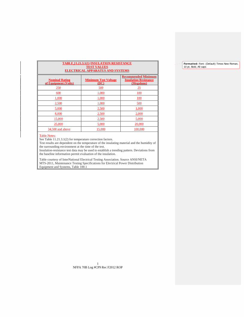
1 NFPA 70B Log #CP9 Rec F2012 ROP
TABLE 11.21.3.1(1) INSULATION RESISTANCE TEST VALUES
ELECTRICAL APPARATUS AND SYSTEMS
Nominal Rating of Equipment (Volts)
Minimum Test Voltage (DC)
Recommended MinimumInsulation Resistance
(Megohms)250 500 25
600 1,000 100
1,000 1,000 100
2,500 1,000 500
5,000 2,500 1,000
8,000 2,500 2,000
15,000 2,500 5,000
25,000 5,000 20,000
34,500 and above 15,000 100,000
Table Notes: See Table 11.21.3.1(2) for temperature correction factors. Test results are dependent on the temperature of the insulating material and the humidity of the surrounding environment at the time of the test. Insulation-resistance test data may be used to establish a trending pattern. Deviations from the baseline information permit evaluation of the insulation.
Table courtesy of InterNational Electrical Testing Association. Source ANSI/NETA MTS-2011, Maintenance Testing Specifications for Electrical Power Distribution Equipment and Systems, Table 100.1
Formatted: Font: (Default) Times New Roman,10 pt, Bold, All caps

1 NFPA 70B Log #CP9 Rec F2012 ROP
TABLE 11.21.3.1(2) INSULATION RESISTANCE CONVERSION
FACTORS (20° C)
Temperature Multiplier
° C ° F Apparatus Containing Solid Insulation
-10 14 0.25
-5 23 0.32
0 32 0.40
5 41 0.50
10 50 0.63
15 59 0.81
20 68 1.00
25 77 1.25
30 86 1.58
35 95 2.00
40 104 2.50
45 113 3.15
50 122 3.98
55 131 5.00
60 140 6.30
65 149 7.90
70 158 10.00
75 167 12.60
80 176 15.80
85 185 20.00
90 194 25.20
95 203 31.60
100 212 40.00
105 221 50.40
110 230 63.20
Table Notes: Source ANSI/NETA MTS-2011, Maintenance Testing Specifications for Electrical Power Distribution Equipment and Systems, Table 100.14.

Report on Proposals – November 2012 NFPA 70B11.21.3.3.1.1 . A dc withstand voltage test, also commonly referred to asa dc high-potential or dc hipot test, consists of applying dc voltage across a cable at or above the dc equivalent of the 60Hz operating crest voltage. This test can be applied either as a dielectric absorption test or a step-voltage test. A dchigh-potential test is an appropriate method for an acceptance test. The dc withstand voltage test should not be appliedto cables over five years old.
11.21.3.3.1.2 . An ac withstand voltage test at power line (60 Hz)frequencies stresses the cable insulation system by applying an ac voltage waveform similar to what the cable wouldexperience in normal operation. It is also a similar test to the factory test on new cables.
11.21.3.3.1.3 . A very low frequency (VLF) test is a withstandvoltage test of cable system insulation. The test is similar to a dc withstand voltage (dc hipot) test except the VLF testunit provides an ac voltage in the frequency range from 0.01 Hz to 1.0 Hz. To successfully pass the test, the cablesystem must withstand the test voltage (usually 3 times rated voltage or less) for a specified time (usually 1 hour orless).
11.21.3.3.2
11.21.3.3.2.1 Also called loss angle or insulation power factor testing, it is adiagnostic method of testing cables to determine the loss factor of the insulation material. Because the loss factorincreases during the ageing process of the cable, the dissipation factor measurement can be used as a diagnosticmethod to predict overall cable health.
For cables, the dissipation factor of each conductor with respect to ground should be obtained, and a hot-collar testshould be performed on each pothead or porcelain termination assembly.
11.21.3.3.2.2 . The insulation system of a medium-voltage distributionsystem has partial discharges into air, across surfaces, and through the insulating material. These discharges emitenergy in various parts of the electromagnetic spectrum. Partial discharges appear as individual events of very shortduration and are always accompanied by emissions of light, sound and heat, as well as electromagnetic pulses; andoften result in chemical reactions.
The severity of these discharges is an indication of the “health” of the insulation system. PD testing measures thesedischarges off-line or on-line and compares them to a database of discharge signatures to determine the severity.
11.21.3.3.2.2.1 . Some of the different methods of measuring PD are as follows:(1) Radio frequency interference (RFI) detection: uses an RF sensor to measure PD pulses occurring in an insulationsystem.(2) Electromagnetic detection: can be made with oscilloscopes combined with other detectors.(3) Acoustical detection: uses an ultrasonic sensor to detect PD. With power cables this method is usually applied toterminations, joints, and cable sections that are accessible so that direct contact with the device under test can beachieved.(4) Ultraviolet detection: uses a camera that “sees” discharges into air or across surfaces.
11.21.3.3.2.2.2 . Some advantages of off-line PD testing are:(1) There is no direct interface with electrical components while under normal source power.(2) PD sites can be more accurately located in an insulation system.(3) Partial discharge inception voltage (PDIV) and partial discharge extinction voltage (PDEV) can be measured if avariable voltage source is used.(4) PD characteristics can be obtained at different voltages, which can aid in the identification of certain types of defects.
11.21.3.3.2.2.3 . Some advantages of on-line PD testing are:(1) Cables are not disconnected.(2) PD characteristics can be obtained while the equipment is under normal load connection, operation, and loadingpatterns which can help identify certain types of defects.(3) A system outage interrupting normal operations is not required.
Medium and high voltage cable testing practices and methods were added and updated.
33Printed on 10/31/2011

Report on Proposals – November 2012 NFPA 70B
Affirmative: 141 Wyman, B.
34Printed on 10/31/2011
Report on Proposals – November 2012 NFPA 70B_______________________________________________________________________________________________70B-40 Log #75 EEM-AAA
_______________________________________________________________________________________________Michael A. Anthony, University of Michigan / Rep. APPA.ORG - Leadership in Education
Add to the list of electrical system tests -- utility impedance testChapter 11 Testing and Test Methods
11.1 Introduction.11.2 Acceptance Tests and Maintenance Tests.11.3 As-Found and As-Left Tests.11.4 Frequency of Tests.11.5 Special Precautions and Safety.11.6 Qualifications of Test Operators.11.7 Test Equipment.11.8 Forms.11.9 Insulation Testing.11.10 Low Voltage Circuit Breakers.11.11 Transformer Tests.11.12 Protective Relays.11.13 Grounding Systems.11.14 Battery Testing.11.15 Switches.11.16 Medium and High Voltage Circuit Breakers.11.17 Infrared Inspection.11.18 Fuses.11.19 Insulating-Liquid Analysis.11.20 Rotating Machine Testing.11.21 Cables.11.22 Adjustable-Speed Drive Testing.11.23 Switchgear and Switchboard Assemblies.11.24 Surge Arresters.11.25 Power Factor Correction Capacitors.11.26 Emergency Systems.
This information is important for short circuit studies and flash hazard analysis -- particularly in utilityservices in district energy systems and where the last mile of distribution is dynamically changing in smart griddistributed control.The instrument can be a one-time, or a recording meter, one that is permanently built. I have provided a photo and the
IEEE paper describing this device.As the author of this proposal, I am grateful to all of the authors of the IEEE paper I have provided (Using a
Microporcessor-Based Instrument to Predict the Incident Energy From Arc-Flash Hazards) who built four of thesedevices and were generous with their time in describing the tests and results. They are, as follows:Thomas L. BaldwinMichael J. HittelLynn F. SaundersFrank Renovich, Jr.My hope is that equipment manufacturers will take notice and begin manufacturing utility impedance meters
("Z-meters") as stand-alone devices, or as a function in an existing package of service switchgear instrumentation.Note: Supporting material is available for review at NFPA Headquarters.
The committee finds that the submitter did not provide sufficient technical substantiation and nomaintenance tasks were listed below.
35Printed on 10/31/2011

Report on Proposals – November 2012 NFPA 70BAffirmative: 14
1 Wyman, B.
36Printed on 10/31/2011
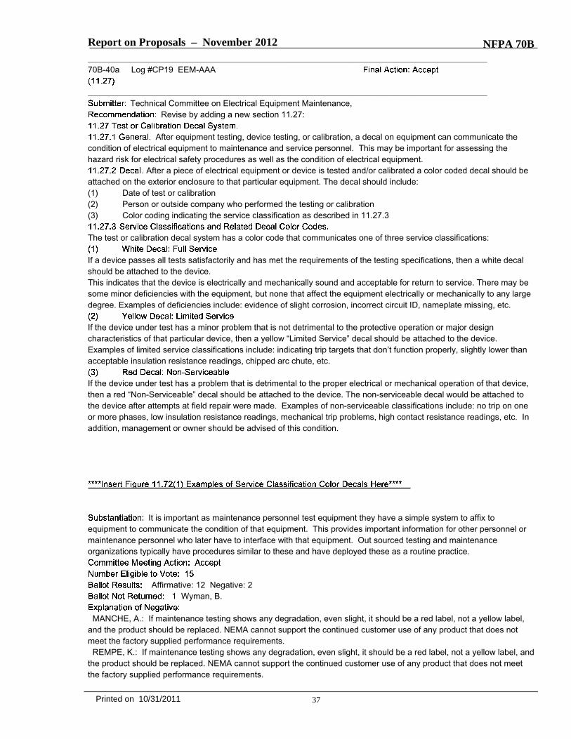
Report on Proposals – November 2012 NFPA 70B_______________________________________________________________________________________________70B-40a Log #CP19 EEM-AAA
_______________________________________________________________________________________________Technical Committee on Electrical Equipment Maintenance,
Revise by adding a new section 11.27:
After equipment testing, device testing, or calibration, a decal on equipment can communicate thecondition of electrical equipment to maintenance and service personnel. This may be important for assessing thehazard risk for electrical safety procedures as well as the condition of electrical equipment.
. After a piece of electrical equipment or device is tested and/or calibrated a color coded decal should beattached on the exterior enclosure to that particular equipment. The decal should include:(1) Date of test or calibration(2) Person or outside company who performed the testing or calibration(3) Color coding indicating the service classification as described in 11.27.3
The test or calibration decal system has a color code that communicates one of three service classifications:
If a device passes all tests satisfactorily and has met the requirements of the testing specifications, then a white decalshould be attached to the device.This indicates that the device is electrically and mechanically sound and acceptable for return to service. There may besome minor deficiencies with the equipment, but none that affect the equipment electrically or mechanically to any largedegree. Examples of deficiencies include: evidence of slight corrosion, incorrect circuit ID, nameplate missing, etc.
If the device under test has a minor problem that is not detrimental to the protective operation or major designcharacteristics of that particular device, then a yellow “Limited Service” decal should be attached to the device.Examples of limited service classifications include: indicating trip targets that don’t function properly, slightly lower thanacceptable insulation resistance readings, chipped arc chute, etc.
If the device under test has a problem that is detrimental to the proper electrical or mechanical operation of that device,then a red “Non-Serviceable” decal should be attached to the device. The non-serviceable decal would be attached tothe device after attempts at field repair were made. Examples of non-serviceable classifications include: no trip on oneor more phases, low insulation resistance readings, mechanical trip problems, high contact resistance readings, etc. Inaddition, management or owner should be advised of this condition.
It is important as maintenance personnel test equipment they have a simple system to affix toequipment to communicate the condition of that equipment. This provides important information for other personnel ormaintenance personnel who later have to interface with that equipment. Out sourced testing and maintenanceorganizations typically have procedures similar to these and have deployed these as a routine practice.
Affirmative: 12 Negative: 21 Wyman, B.
MANCHE, A.: If maintenance testing shows any degradation, even slight, it should be a red label, not a yellow label,and the product should be replaced. NEMA cannot support the continued customer use of any product that does notmeet the factory supplied performance requirements.REMPE, K.: If maintenance testing shows any degradation, even slight, it should be a red label, not a yellow label, and
the product should be replaced. NEMA cannot support the continued customer use of any product that does not meetthe factory supplied performance requirements.
37Printed on 10/31/2011

*** Include CP 19 Figure 11.72(1) ***
Figure 11.72(1) Graphic Example of Service Classification Color Decals Non-Serviceable
Date: ____________ By: ______________
Limited Service Date: ____________ By: ______________
Serviceable Date: ____________ By: ______________

Report on Proposals – November 2012 NFPA 70B
CRNKO, T.: I agree with Mr. White's affirmative comment. This type of calibration decal system has been widely usedfor decades by testing and maintenance service providers and serves an important function for workers andmanagement. Concerning the comments by Mr. Manche and Mr. Rempe, the yellow decal for limited service is notintended to be for devices that would pose a safety hazard or would not function per specification. Possibly moreexplicit language edit in ROC cycle would help clarify.WHITE, J.: Calibration stickers are a proven method to advise electrical technicians and operators of the current
status of electrical power system equipment. With the calibration stickers in place, a worker no longer is required toguess at the state of the equipment's condition or attempt to find results of the latest maintenance performed. Byplacing a small label on the outside surface of the device or equipment it provides timely information without interferingwith operation or longevity of those devices. This practice has been used for decades by several NETA-membercompanies with no issues. One other benefit of the labeling is that equipment owners are reminded that servicing isneeded whenever they see the label. The yellow label is only used for minor issues that do not affect worker safety,while the red label indicates a serious maintenance issue that needs immediate resolution. The white label assures thatthe equipment is operating in a normal manner. All of these work together to provide a safer work environment
_______________________________________________________________________________________________70B-41 Log #36 EEM-AAA
_______________________________________________________________________________________________John F. Bender, Underwriters Laboratories Inc.
Revise text as follows:A device intended for the protection of personnel that functions to
deenergize a circuit or portion thereof within an established period of time when a current to ground exceeds the valuesestablished for a Class A device. Note: Class A Ground-Fault Circuit Interrupters trip when the current to ground has avalue in the range of 4 mA to 6 mA. For further information, see ANSI/UL 943,
. [70, 2008].Add ANSI approval designation to ANSI/UL 943.
The committee rejects this proposal because the extracted definition from the NEC does notinclude the ANSI designation.
Affirmative: 141 Wyman, B.
38Printed on 10/31/2011

Report on Proposals – November 2012 NFPA 70B_______________________________________________________________________________________________70B-42 Log #72 EEM-AAA
_______________________________________________________________________________________________Michael A. Anthony, University of Michigan / Rep. APPA.ORG - Leadership in Education - Association of
Education Facility ExecutivesAfter the section on solidly grounded systems, add more technical information add new section
14.1.6.46+ (NEW)Solidly grounded means that the grounded conductor is grounded without inserting any
resistor or impedance device.Neutral Grounding Resistors (NGR’s) limit the fault current when
one phase of the system shorts or arcs to ground. In the event that a ground fault condition exists, the NGR typicallylimits the current to 200-400A, though most resistor manufacturers label any resistor that limits the current to 25A orgreater as low resistance.
High Resistance Grounding (HRG) systems limit the fault currentwhen one phase of the system shorts or arcs to ground, but at lower levels than low resistance systems. In the eventthat a ground fault condition exists, the HRG typically limits the current to 5-10A, though most resistor manufacturerslabel any resistor that limits the current to 25A or less as high resistance.
Low Resistance Grounding:1. Limits phase-to-ground currents to 200-400A.2. Reduces arcing current and, to some extent, limits arc-flash hazards
associated with phase-to-ground arcing current conditions only.3. May limit the mechanical damage and thermal damage to shorted transformer and rotating machinery windings.4. Does not prevent operation of overcurrent devices.5. Does not require a ground fault detection system.6. May be utilized on medium or high voltage systems. GE offers low resistance grounding systems up to 72kV
line-to-line.7. Conductor insulation and surge arrestors must be rated based on the lineto- line voltage. Phase-to-neutral loads
must be served through an isolation transformer.High Resistance Grounding:1. Limits phase-to-ground currents to 5-10A.2. Reduces arcing current and essentially eliminates arc-flash hazards associated with phase-to-ground arcing current
conditions only.3. Will eliminate the mechanical damage and may limit thermal damage to shorted transformer and rotating machinery
windings.4. Prevents operation of overcurrent devices until the fault can be located (when only one phase faults to ground).5. Requires a ground fault detection system to notify the facility engineer that a ground fault condition has occurred.6. May be utilized on low voltage systems or medium voltage systems up to 5kV. IEEE Standard 141-1993 states that
“high resistance grounding should be restricted to 5kV class or lower systems with charging currents of about 5.5A orless and should not be attempted on 15kV systems, unless proper grounding relaying is employed”.7. Conductor insulation and surge arrestors must be rated based on the lineto- line voltage. Phase-to-neutral loads
must be served through anisolation transformer.Resistance Grounding Systems have many advantages over solidly grounded systems including arc-flash hazard
reduction, limiting mechanical and thermal damage associated with faults, and controlling transient overvoltages. Highresistance grounding systems may also be employed to maintain service continuity and assist with locating the sourceof a fault. When designing a system with resistors, the design/consulting engineer must consider the specificrequirements for conductor insulation ratings, surge arrestor ratings, breaker single-pole duty ratings, and method ofserving phase-to-neutral loads.
Engineers and facility managers who design, build and operate campus-style bulk distribution grids arestruggling with economical ways to provide electrical power reliably and safely (i.e. reducing flash energy). Lowresistance grounded systems for campus style medium voltage distribution has particular advantages if migration to lowresistance grounding from solidly grounded systems can be scaled incrementally. As long as some of the cableinsulation issues can be managed, low resistance grounding is a near-silver bullet solution to many of the maintenanceproblems associated with very high incident energy at primary equipment for the most common type of fault - thephase-to-ground fault.
39Printed on 10/31/2011

Report on Proposals – November 2012 NFPA 70BThe electrical engineers who are retained by Architects in education facilities projects, for example, should present
resistance grounding options their clients as a safety and maintenance solution. Installing this passage into NFPA 70Bwill enliven the discussion among planners and designers of campus-style medium voltage distribution grids as well asinform many smart-grid, interactive grid concepts going forward.Much of this material has been derived from the following sources:"Resistance Grounding System Basics", By Michael D. Seal, P.E., General Electric E Senior Specification Engineer
and "Innovative Techniques for Mitigating Arc Flash Exposure" by David Shipp at Eaton Corporation.
The committee rejects because there are no action statements and maintenance tasksrequired. The committee further finds that it is tutorial in nature and does not enhance the purpose of the document.The committee recognizes the value of this information as design criteria.
Affirmative: 141 Wyman, B.
_______________________________________________________________________________________________70B-42b Log #CP4 EEM-AAA
_______________________________________________________________________________________________The Technical Correlating Committee directs that the committee review the proposed text and either list all
the possible wiring methods available or refer the user of the document to NFPA 70 for further grounding informationand requirements. This shall be considered as a public comment.
Technical Committee on Electrical Equipment Maintenance,Add new section 14.1.6.49
14.1.6.49 .14.1.6.49.1 Inspect to verify that the luminaires (fixtures) are properly grounded.(1) If the wiring method utilizes a metallic armored cable wiring method or nonmetallic-sheathed cable with ground,proper connection of the wiring provides an acceptable equipment ground. Grounding of a surface-mounted luminaire isaccomplished by securing the luminaire to a properly grounded metal outlet box. Metal outlet boxes have a location toplace a grounding screw. The bare copper equipment grounding conductor in the nonmetallic sheathed cable is usuallyterminated under this screw.(2) If the outlet box is nonmetallic, the small bare equipment grounding conductor from the luminaire is connected to theequipment grounding conductor in the outlet box. For suspended ceiling luminaires, grounding of the luminaire isaccomplished by using metallic fixtures whips or nonmetallic-sheathed cable with ground between the outlet box and theluminaire.14.1.6.49.2 If there is no equipment grounding means found, refer to NFPA 70 for proper grounding.
In reviewing the lighting chapter 23, it was noted that proper grounding of luminaires should be coveredin the maintenance inspection procedure. It was determined that the new material would be more appropriately placedin the grounding chapter.
Affirmative: 141 Wyman, B.
40Printed on 10/31/2011

Report on Proposals – November 2012 NFPA 70B_______________________________________________________________________________________________70B-43 Log #42 EEM-AAA
_______________________________________________________________________________________________Steve McCluer, Schneider Electric / Rep. IEEE Stationary Battery Committee
Revise text to read as follows:Stationary batteries are a primary power source for critical systems, ac power generation
equipment, switchgear, and control circuits. Stationary batteries also provide backup power for essential equipmentduring outages of the primary power supply. Because these applications require reliable service, stationary batteriesshould be serviced regularly. The maintenance required depends on each battery’s application, type, constructionfeatures and materials, and environment.
Lead–acid batteries are of two technologies: flooded wet cell design and sealed valve regulated lead–acid(VRLA) designs. Stationary batteries are typically lead–acid batteries with lead–antimony or lead–calcium grids. Somestationary batteries are nickel–cadmium (Ni-Cad) units. VRLA batteries have a shorter service life than flooded cells,cannot be tested in the same manner, and are not addressed in this document.
Battery chargers play a critical role in battery maintenance because they supply normal dc requirementsand maintain batteries at appropriate levels of charge. Chargers should be set and maintained according tomanufacturers’ instructions.
Stationary batteries are most often used as the reserve power source for critical equipment duringpower outages. These batteries are typically vented lead-acid (VLA) batteries consisting of either lead calcium or leadantimony grids. Other technologies may be utilized in these applications but are not specifically addressed in thefollowing paragraphs. Due to the reliability requirements for these applications, specific safety guidelines as well as welldefined maintenance practices should be utilized to ensure a reliable system. The following sections offer guidance onthe safety and maintenance requirements. In addition, the manufacturers’ recommendations should be followed and theappropriate IEEE standards should be referred to for additional information.
This proposal is one of a series by the IEEE Stationary Battery committee.● The existing “General” paragraph does not summarize the intent of Section 15.9.4. It mentions things that are not
actually discussed later.● Paragraph 15.9.4.1.2 can be deleted as it is commentary and adds no guidance for procedures.● Chargers should be beyond the scope of para 15.9.4., which is actually about batteries with only the briefest mention
of chargers.● Almost all batteries used in substation and switchgear applications are vented lead-acid, with an occasional VRLA or
Ni-Cd (described as “other technologies” in this proposal).● Many of the subsequent paragraphs in the 2010 edition address only vented lead-acid batteries.A separate proposal recommends the addition of a new section for references to battery maintenance standards.
Revise the text of the recommendation to read as follows:15.9.4.1 General. Stationary batteries are a power source for critical systems, ac power generation equipment,
switchgear, and control circuits. Stationary batteries are most often used as the reserve power source for criticalequipment during power outages. These batteries are typically vented lead-acid (VLA) batteries consisting of either leadcalcium or lead antimony grids. Other technologies may be utilized in these applications but are not specificallyaddressed in the following paragraphs. Due to the reliability requirements for these applications, specific safetyguidelines as well as well defined maintenance practices should be utilized to ensure a reliable system. The followingsections offer guidance on the safety and maintenance requirements. In addition, the manufacturers’ recommendationsshould be followed and the appropriate applicable IEEE standards should be referred to for additional information.
Lead–acid batteries are of two technologies: flooded wet cell design and sealed valve regulated lead–acid(VRLA) designs. Stationary batteries are typically lead–acid batteries with lead–antimony or lead–calcium grids. Somestationary batteries are nickel–cadmium (Ni-Cad) units. VRLA batteries have a shorter service life than flooded cells,
41Printed on 10/31/2011

Report on Proposals – November 2012 NFPA 70Bcannot be tested in the same manner, and are not addressed in this document..
15.9.4.1.1 Battery chargers play a critical role in battery maintenance because they supply normal dcrequirements and maintain batteries at appropriate levels of charge. Chargers should be set and maintained accordingto manufacturers’ instructions.
The committee accepts the revisions to 15.9.4.1 and added a new first sentence to clarify thefunction of the battery in these types of systems and changed "appropriate" to "applicable" in the last sentence.The committee accepts the deletion of 15.9.4.1.1.The committee rejects the removal of 15.9.4.1.2 and has renumbered it as 15.9.4.1.1. The committee finds that the
information is important to the user of the document and the substantiation was not sufficient to justify its removal sincethe battery charger is an integral part of the system.
Affirmative: 141 Wyman, B.
_______________________________________________________________________________________________70B-44 Log #43 EEM-AAA
_______________________________________________________________________________________________Steve McCluer, Schneider Electric / Rep. IEEE Stationary Battery Committee
Add new text to read as follows:The following should be considered for specific maintenance, repair considerations, and
procedures:(1) IEEE Std 450 – IEEE Recommended Practice for Maintenance, Testing and Replacement of Vented Lead-Acid
Batteries for Stationary Applications(2) IEEE Std 1188 – IEEE Recommended Practice for Maintenance, Testing and Replacement of Valve-Regulated
Lead-Acid (VRLA) Batteries for Stationary Applications(3) IEEE Std 1106 – IEEE Recommended Practice for Installation, Maintenance, Testing and Replacement of Vented
Nickel-Cadmium Batteries for Stationary Applications(4) IEEE Std 1145 – IEEE Recommended Practice for Installation and Maintenance of Nickel-Cadmium Batteries for
Photovoltaic (PV) Systems(5) IEEE Std 1657 – IEEE Recommended Practice for Personnel Qualifications for Installation and Maintenance of
Stationary BatteriesThis proposal would add a section for references. The paragraph number depends upon action on
other proposals.Items 1-4 cite industry standards for maintenance of vented lead-acid, VRLA, and Ni-Cd batteries.Item 5 cites a recent standard for certification of battery technicians in order to identify an individual as “qualified.”
Affirmative: 141 Wyman, B.
42Printed on 10/31/2011
Report on Proposals – November 2012 NFPA 70B_______________________________________________________________________________________________70B-45 Log #44 EEM-AAA
_______________________________________________________________________________________________Steve McCluer, Schneider Electric / Rep. IEEE Stationary Battery Committee
Revise text to read as follows:Battery maintenance normally consists of periodic inspections and tests. As a minimum, a
maintenance program should be established based on manufacturers’ installation and operation manuals. Ideally, otherstandards such as IEEE recommended practices applicable to the battery design may also be consulted, as these arefrequently called out in the manufacturer’s manuals. For further information on testing see 11.14, Battery Testing. Visualinspections include checking electrolyte level and internal conditions in jar-type cells. Many battery problems can bedetected by visual inspections. Tests aid in evaluating performance and permit comparisons with standards and withhistorical test results. Battery manufacturers are good sources of information for maintenance programs.
Delete sentences #2 through 5 of paragraph 15.9.4.2 as they do not give any specifics about whatvisual inspection should look for on any given type of battery or how to interpret what is observed.The revised text clarifies that procedures will vary from one battery technology to another. For example, checking
electrolyte levels is not possible on a VRLA battery. Detailed procedures are provided by the battery manufacturersand/or standards written specifically for the type of battery. The existing text references “standards” but doesn't identifywhat they are. IEEE standards are the most commonly referenced standards for stationary battery installation andmaintenance. A separate proposal recommends adding a paragraph in 15.9.4 to list the appropriate standards (whichare also included in 11.14.1).In the final sentence we recommend add the name of the referenced section in NFPA 70B.
Revise the text of the recommendation to read as follows:Battery maintenance normally consists of periodic inspections and tests. As a minimum, a
maintenance program should be established based on manufacturers’ installation and operation manuals. Ideally, otherstandards such as IEEE recommended practices applicable to the battery design may also be consulted, as these arefrequently called out in the manufacturer’s manuals. For further information on testing see 11.14, Battery Testing. Visualinspections include checking electrolyte level and internal conditions in jar-type cells. Many battery problems can bedetected by visual inspections. Tests aid in evaluating performance and permit comparisons with standards and withhistorical test results. Battery manufacturers are good sources of information for maintenance programs.
The committee did not accept the wording referring to IEEE recommended practices because itis adequately covered in the Committee Action taken Proposal 70B-43 (Log #42).
Affirmative: 141 Wyman, B.
43Printed on 10/31/2011

Report on Proposals – November 2012 NFPA 70B_______________________________________________________________________________________________70B-46 Log #45 EEM-AAA
_______________________________________________________________________________________________Steve McCluer, Schneider Electric / Rep. IEEE Stationary Battery Committee
Revise text to read as follows:Personnel should be aware of the hazards associated with stationary batteries. Voltages
present can cause injury and death Exposing skin and eyes to electrolyte can cause severe burns and blindness Abattery can produce and emit a mixture of hydrogen and oxygen gas that is explosive. Vented lead-acid batteries canemit a mixture of hydrogen and oxygen gas. Under abnormal conditions, such as a lack of space ventilation, it ispossible for the mixture to reach a flammable level. Exposing skin and eyes to electrolyte can cause severe burns andblindness. Voltages present can cause injury and death. As a minimum, the safety precautions in 15.9.4.3.1 through15.9.4.3.7 should be observed.
The existing language of 15.9.4.3 exaggerates the hazards. A vented battery that is properly installed,maintained, and operated in a properly ventilated space will not create explosive levels of gas. It is only under abnormalconditions that such a condition can occur. We recommend reorganizing the list of hazards by priority, with electricalshock being the greatest concern.
Affirmative: 141 Wyman, B.
44Printed on 10/31/2011

Report on Proposals – November 2012 NFPA 70B_______________________________________________________________________________________________70B-47 Log #46 EEM-AAA
_______________________________________________________________________________________________Steve McCluer, Schneider Electric / Rep. IEEE Stationary Battery Committee
Revise text to read as follows:Maintenance personnel should be trained to perform the tasks properly . Training should include using personal
protective equipment, handling the electrolyte safely, using the proper tools, and following the battery manufacturer’sservice and maintenance instructions and using recommended tools.
This list in 15.9.4.3.1 is not all-inclusive. Refer to the manufacturer’s instructions for the skills requiredfor a specific battery technology, and which frequently refer to other standards such as IEEE battery standards andNFPA 70E. The latter go into more detail about the levels and types of skills required. IEEE Standard 1657 givesdetailed curriculum for certifying battery technicians in order to determine when a person is “qualified”.
The substantiation does not give adequate reason for removing the requirements.
Affirmative: 141 Wyman, B.
_______________________________________________________________________________________________70B-48 Log #47 EEM-AAA
_______________________________________________________________________________________________Steve McCluer, Schneider Electric / Rep. IEEE Stationary Battery Committee
Delete text as follows:The room or compartment in which operating lead–acid batteries are located should be ventilated
adequately.Delete paragraph 15.9.4.3.2 and renumber subsequent paragraphs. This is a design issue, not a
maintenance issue. This requirement is appropriate for the National Electrical Code, Fire Code, or Mechanical Code. Itis inappropriate for an electrical equipment maintenance standard. The appropriate battery maintenance is to verify thatany room or compartment ventilation system is operating. Paragraph 15.9.4.4.6 addresses inspection of ventilationsystem(s).
The committee does not agree that determining if adequate ventilation is available is a designissue.
Affirmative: 141 Wyman, B.
45Printed on 10/31/2011

Report on Proposals – November 2012 NFPA 70B_______________________________________________________________________________________________70B-49 Log #48 EEM-AAA
_______________________________________________________________________________________________Steve McCluer, Schneider Electric / Rep. IEEE Stationary Battery Committee
Revise text to read as follows:Appropriate safety equipment should be worn used in accordance with NFPA 70E and manufacturer’s
instructions. , including goggles, gloves, and aprons, by persons working with the batteries. Eyewash and quick drenchfacilities should be provided near the batteries.
NFPA 70E and the battery manufacturers specify the safety equipment and tools for battery installationand maintenance. Safety equipment also includes items that are not “worn”.Provision for eye wash stations is a facility design issue, not a maintenance issue. Installation requirements are the
jurisdiction of the National Electrical Code.
Affirmative: 141 Wyman, B.
_______________________________________________________________________________________________70B-50 Log #49 EEM-AAA
_______________________________________________________________________________________________Steve McCluer, Schneider Electric / Rep. IEEE Stationary Battery Committee
Revise text to read as follows:Metal Conductive objects should not be placed on used near battery cells. Insulated tools should be used to protect
against shorting of cells.Replace “metal” with “conductive,” as objects can be conductive but not necessarily metal. Conductive
objects should not be placed on or used near the conductive elements of a battery system.
Affirmative: 141 Wyman, B.
46Printed on 10/31/2011
Report on Proposals – November 2012 NFPA 70B_______________________________________________________________________________________________70B-51 Log #50 EEM-AAA
_______________________________________________________________________________________________Steve McCluer, Schneider Electric / Rep. IEEE Stationary Battery Committee
Delete text as follows:When electrolyte is being prepared, personal protective equipment should include a full face shield. POUR
ACID INTO WATER, NOT WATER INTO ACID. If the electrolyte comes in contact with skin or eyes, the affected areashould be immediately flushed with water and medical assistance obtained
Delete paragraph 15.9.4.3.6. PPE is addressed in other paragraphs. Mixing acid and water in thefield is not a standard practice (is really the rare exception). The standard practice is just to add water to a cell. On therare occasions when the addition of acid is required, the electrolyte is almost always obtained from the manufacturer atthe proper specific gravity.We should point out that this document also addresses Nickel-Cadmium batteries. You never put acid in a Ni-Cd
battery, in which the active chemical is Potassium Hydroxide (an alkaline agent). Refer to the MSDS for the appropriatefirst aid for the chemicals in a specific type of battery.
Affirmative: 141 Wyman, B.
_______________________________________________________________________________________________70B-52 Log #51 EEM-AAA
_______________________________________________________________________________________________Steve McCluer, Schneider Electric / Rep. IEEE Stationary Battery Committee
Revise text to read as follows:Unauthorized access to the battery area exposed batteries should be prohibited.
As written, this paragraph only applies when the batteries are located in a battery room or otherrestricted area in which batteries are installed in open racks. Often batteries are collocated with other equipment whereaccess is required by several technical and operating personnel, in which case batteries are typically secured incabinets. In these cases, cabinets should be locked and appropriate warning signs should be displayed.
Affirmative: 141 Wyman, B.
47Printed on 10/31/2011

Report on Proposals – November 2012 NFPA 70B_______________________________________________________________________________________________70B-53 Log #52 EEM-AAA
_______________________________________________________________________________________________Steve McCluer, Schneider Electric / Rep. IEEE Stationary Battery Committee
Revise text as follows:
Reword the title of paragraph 15.9.4.4. to clarify that it is for visual inspections only, of both mechanicaland electrical equipment. All of the following sub-paragraphs address only visual inspection.
Affirmative: 141 Wyman, B.
_______________________________________________________________________________________________70B-54 Log #53 EEM-AAA
_______________________________________________________________________________________________Steve McCluer, Schneider Electric / Rep. IEEE Stationary Battery Committee
Revise text to read as follows:Jars Containers and covers should be checked for cracks and structural damage. Maintenance of flame arrester–type
vent caps should consist of rinsing them in clear water and air drying. Damaged units and damaged or missingremovable vent caps should be replaced.
The slang term “jars” is technically incorrect; the term “container” should be substituted wherever theterm “jars” is used in this document.Cleaning of flame arrestors is not a standard battery maintenance routine and is not recommended as it can introduce
contaminants into the electrolyte, it can create a potentially hazardous condition if flame arrestors are removed morethan briefly, and flame arrestor vent caps cannot be serviced on VRLA or similar batteries. Damaged or missing ventcaps should be replaced.
Affirmative: 141 Wyman, B.
48Printed on 10/31/2011

Report on Proposals – November 2012 NFPA 70B_______________________________________________________________________________________________70B-55 Log #70 EEM-AAA
_______________________________________________________________________________________________Steve McCluer, Schneider Electric / Rep. IEEE Stationary Battery Committee
Revise text to read as follows:Plates and internal parts of within clear jars containers should be checked for damages such as buckling,
warping, scaling, swelling, cracking, hydration rings, excessive sedimentation, mossing, copper contamination, internalpost seal cracks, and changes in color. Damaged Questionable cells should be replaced.evaluated for repair orreplacement.
The term “jars” is technically incorrect; the term “container” should be used wherever the term “jars” isused in this document. Internal parts should also be checked for a lot more than what is presently identified. Sometimesminor damage can be repaired. Some degree of battery defect can be tolerated or repaired.
Revise the recommendation as follows:Plates and internal parts of within clear jars containers should be checked for damages such as buckling,
warping, scaling, swelling, cracking, hydration rings, excessive sedimentation, mossing, copper contamination, internalpost seal cracks, and changes in color. Damaged Questionable Cells Eexhibiting any of these characterisitcs cellsshould be replaced. evaluated for repair or replacement.
The committee changed the word "damages" to "damage for editorial purposes and the lastsentence of the recommended text was revised to provide clarity and eliminate subjective wording.
Affirmative: 141 Wyman, B.
_______________________________________________________________________________________________70B-56 Log #71 EEM-AAA
_______________________________________________________________________________________________Steve McCluer, Schneider Electric / Rep. IEEE Stationary Battery Committee
Revise text to read as follows:The charger should be checked for proper operation. Interconnection cables, cell connectors, and other
conductors should be examined for wear, contamination, corrosion, and discoloration. Racks should be checked forcorrosion, cleanliness, proper grounding, and structural integrity.
Grounding can also be affected by the same issues cited in the previous sentence.
Affirmative: 141 Wyman, B.
49Printed on 10/31/2011
Report on Proposals – November 2012 NFPA 70B_______________________________________________________________________________________________70B-57 Log #69 EEM-AAA
_______________________________________________________________________________________________Steve McCluer, Schneider Electric / Rep. IEEE Stationary Battery Committee
Revise text to read as follows:A check should be made for spilled electrolyte. A solution of water and bicarbonate of soda (baking soda)
solution should be used to neutralize lead–acid battery spills, and a solution of boric acid and water solution should beused for Ni-Cad spills. The battery manufacturer’s instructions should be consulted for proper proportions.
Battery manufacturer’s instructions would indicate the proper solution and dilution.
Affirmative: 141 Wyman, B.
50Printed on 10/31/2011
Report on Proposals – November 2012 NFPA 70B_______________________________________________________________________________________________70B-58 Log #54 EEM-AAA
_______________________________________________________________________________________________Steve McCluer, Schneider Electric / Rep. IEEE Stationary Battery Committee
Revise text to read as follows:The electrolyte level before water addition, should be checked and corrective measures should be noted in
accordance with the owner’s maintenance program and the manufacturer’s recommendations. It should be determinedthat electrolyte and cells are clear, with minimal deposits, gassing, or rings, and that there is only minor sediment belowthe plates. The amounts of water added to the cells should be recorded. Excessive water consumption can be a sign ofovercharging or cell damage. For lead–antimony batteries, water consumption increases gradually with age. Distilled ordeionized water should be used unless otherwise recommended by the battery manufacturer.
Never add acid anything but water to a battery when refilling. unless recommended to do so by themanufacturer.
● It is assumed that there is already a maintenance program established to address inspection andrecording of electrolyte levels.● The items in the second sentence are already addressed in previous paragraphs (see 15.9.4.4.2)● The 3rd sentence is already addressed w/ revisions to the 1st sentence.● re: 4th sentence: Partial cell shorts can cause excessive water consumption.● In large battery installations it can often be less expensive to install deionization equipment than to buy distilled
water for battery watering. Properly maintained deionization equipment can and does provide perfectly suitable water forbatteries.● re Caution: delete the words “when refilling” as they are not needed. Acid, electrolyte, or anything else should not be
added unless specifically instructed to do so by the manufacturer.
Affirmative: 141 Wyman, B.
51Printed on 10/31/2011
Report on Proposals – November 2012 NFPA 70B_______________________________________________________________________________________________70B-59 Log #55 EEM-AAA
_______________________________________________________________________________________________Steve McCluer, Schneider Electric / Rep. IEEE Stationary Battery Committee
Revise text to read as follows:Ventilation and the suitability and condition of electrical equipment in the area should be checked for its
possible effect on the battery. Battery proximity to combustibles and ignition sources should be evaluated. Local sourcesof heating and cooling can create cell temperature differentials that cause battery damage. Battery room ventilationopenings should be checked to be sure they are clear of obstructions.
Both heating and cooling - or lack thereof - can affect battery performance.Delete the 2nd sentence as it is already addressed in paragraph 15.9.4.3.4Add the final sentence, which is moved from 15.9.4.4.13 because it fits better here (see separate proposal on
15.9.4.4.13).
Affirmative: 141 Wyman, B.
_______________________________________________________________________________________________70B-60 Log #56 EEM-AAA
_______________________________________________________________________________________________Steve McCluer, Schneider Electric / Rep. IEEE Stationary Battery Committee
Revise text to read as follows:Ambient temperature should be checked to be within the manufacturer’s recommended range. The
optimum ambient operating temperature for lead–acid batteries is 2025°C (68 -77°F). Ni-Cad batteries can operatesatisfactorily over a greater range of temperatures, generally from 25°C to 45°C (77 41 °F to 113°F). High ambienttemperatures reduce cell life. Every 9 8.4°C (15°F) increase in temperature above 25°C (77°F) can reduces lead–acidcell life by up to 50 percent and Ni-Cad cell life by up to 20 percent. Lower ambient cell temperatures reduce cellcapacity (A lead-acid battery operating at 16°C (60°F) loses about 10 percent of its designed capacity.
The values cited in the existing text can vary from one manufacturer to another depending upon manyvariables. The technician should make sure that ambient temperature is within the range specified by the batterymanufacturer.
Affirmative: 141 Wyman, B.
52Printed on 10/31/2011

Report on Proposals – November 2012 NFPA 70B_______________________________________________________________________________________________70B-61 Log #57 EEM-AAA
_______________________________________________________________________________________________Steve McCluer, Schneider Electric / Rep. IEEE Stationary Battery Committee
Delete text as follows:Area heating, air conditioning, seismic protection, dc circuit overcurrent protection, distilled water supply,
alarm circuits, grounding connections, cable clamps, and all other installed protective systems and devices should bechecked.
Delete 15.9.4.4.8 and renumber subsequent paragraphs. The activities listed here apply toinfrastructure inspection, not battery maintenance. These responsibilities fall within the infrastructure management groupor the fire marshals’ office.
The committee finds that the substantiation is not sufficient as the section already covers othercomponents of the battery system including building components. Section 15.9.4.4.8 directly applies to visual,mechanical and electrical inspections.
Affirmative: 141 Wyman, B.
_______________________________________________________________________________________________70B-62 Log #58 EEM-AAA
_______________________________________________________________________________________________Steve McCluer, Schneider Electric / Rep. IEEE Stationary Battery Committee
Add new text to read as follows:Voltage potential between the battery’s most positive and most negative terminals should be verified to be
within the manufacturer’s recommended float voltage range for the observed ambient temperature.
High or low voltage can be a sign of charger failure, improper setting, charger malfunction, or excessive voltage drop inthe wiring. This is a charger issue, not a battery issue.
Affirmative: 141 Wyman, B.
53Printed on 10/31/2011

Report on Proposals – November 2012 NFPA 70B_______________________________________________________________________________________________70B-63 Log #59 EEM-AAA
_______________________________________________________________________________________________Steve McCluer, Schneider Electric / Rep. IEEE Stationary Battery Committee
Revise text to read as follows:Lead–acid battery surfaces should be cleaned with a mild solution of water and sodium bicarbonate to
avoid leakage currents caused by electrolyte on the battery. Ni-Cad battery surfaces should be cleaned with a solutionof boric acid and water. solution. Cleaners, soaps, or solvents should not be used to clean battery containers jars andcovers, since damage can result. Consult the battery manufacturer for the proper solution and dilution.
Battery manufacturer’s would indicate the proper solution and dilution.The slang term “jars” should be replaced with the proper term “containers” wherever used in this document.Compare this to Paragraph 15.9.4.4.4
Revise existing text as follows:Lead–acid battery surfaces should be cleaned with a mild solution of water and sodium bicarbonate to
avoid leakage currents caused by electrolyte on the battery. Ni-Cad battery surfaces should be cleaned with a solutionof boric acid and water solution. Cleaners, soaps, or solvents should not be used to clean battery containers jars andcovers, since damage can result. Consult the battery manufacturer for the proper solution and dilution.
The committee did not accept the word "mild" because it is undefined and subjective.
Affirmative: 141 Wyman, B.
54Printed on 10/31/2011

Report on Proposals – November 2012 NFPA 70B_______________________________________________________________________________________________70B-64 Log #60 EEM-AAA
_______________________________________________________________________________________________Steve McCluer, Schneider Electric / Rep. IEEE Stationary Battery Committee
Revise text to read as follows:The intercell connectors (links) should be checked annually and torqued to specified values. All battery
connections should be checked on a routine basis for high connection resistance. When a connection resistance is highthen the connections should be cleaned and re-torqued in accordance with the manufacturer’s procedures.
Many manufacturers no longer recommend to re-torque annually as this practice leads to deformationand over-stressing of the posts. Furthermore, it does not guarantee a good connection.
Revise text to read as follows:The intercell connectors (links) should be checked annually and torqued to specified values. All battery
connections should be checked on a routine basis for high connection resistance. When the resistance of a connectionis in excess of 50% of the lowest measured resistance of similar connections, then the connection should be cleanedand torqued in accordance with the manufacturer’s procedures.
The committee found that the term high resistance connection was subjective and requiredclarification. The source of the 50% resistance value came from ANSI/NETA MTS-2011.
Affirmative: 141 Wyman, B.
55Printed on 10/31/2011

Report on Proposals – November 2012 NFPA 70B_______________________________________________________________________________________________70B-65 Log #61 EEM-AAA
_______________________________________________________________________________________________Steve McCluer, Schneider Electric / Rep. IEEE Stationary Battery Committee
Delete text as follows:Alarm relays, lights, and horns should be checked for proper operation. The battery room emergency
lighting should be checked.Delete paragraph 15.9.4.4.12 and renumber subsequent paragraph(s). Existing text adds no clear
instruction. No guidance is given for what to check for or where to get the information. All of these should be addressedin detail in the owner’s maintenance program manual.The activities listed here describe infrastructure inspection, not battery maintenance. These responsibilities fall within
the infrastructure management group or the fire marshals’ office.
The committee finds that the substantiation is not sufficient as the section already covers othercomponents of the battery system including building components. Section 15.9.4.4.12 directly applies to visual,mechanical and electrical inspections.
Affirmative: 141 Wyman, B.
_______________________________________________________________________________________________70B-66 Log #62 EEM-AAA
_______________________________________________________________________________________________Steve McCluer, Schneider Electric / Rep. IEEE Stationary Battery Committee
Delete text as follows:Battery room ventilation openings should be checked to be sure they are clear of obstructions.
Delete paragraph 15.9.4.4.13 and move the statement to 15.9.4.4.6 where ventilation is addressed.See separate proposal for 15.9.4.4.6.
The committee accepts but acknowledges that the exact wording was relocated to 15.9.4.4.6.See Proposal 70B-59 (Log 55).
Affirmative: 141 Wyman, B.
56Printed on 10/31/2011

Report on Proposals – November 2012 NFPA 70B_______________________________________________________________________________________________70B-67 Log #63 EEM-AAA
_______________________________________________________________________________________________Steve McCluer, Schneider Electric / Rep. IEEE Stationary Battery Committee
Delete text as follows:Excessive gassing can result from overcharging.
Delete paragraph 15.9.4.5.1 and renumber subsequent paragraphs. Gassing is addressed in proposalfor 15.9.4.3.
The committee accepts but acknowledges that the exact wording was relocated to 15.9.4.3.See proposal 70B-46 (Log 45).
Affirmative: 141 Wyman, B.
_______________________________________________________________________________________________70B-68 Log #64 EEM-AAA
_______________________________________________________________________________________________Steve McCluer, Schneider Electric / Rep. IEEE Stationary Battery Committee
Delete text as follows:Vibration reduces battery life. Excessive vibration can be detected by observing vibration of plates and
sediment in the jar.Delete 15.9.4.5.2 and renumber subsequent paragraphs. Vibration does reduce life, but it is more
likely to be a problem before it can be detected by visual observation. If construction next door or some other source ofvibration causes excess sedimentation or plate cracking, there is not much that a maintenance technician can do aboutit.
The committee finds that the proposal's substantiation validates the requirement and does notwarrant removal.
Affirmative: 141 Wyman, B.
57Printed on 10/31/2011

Report on Proposals – November 2012 NFPA 70B_______________________________________________________________________________________________70B-68a Log #CP17 EEM-AAA
_______________________________________________________________________________________________Technical Committee on Electrical Equipment Maintenance,
Add new text as follows:15.9.4.5.2 Vibration reduces battery life. Excessive vibration can be detected by observing vibration of plates and
sediment in the jar. If this condition is observed, then steps to reduce the vibration source, isolate the batteries from thevibration, and/or plan for an earlier scheduled replacement of the batteries than normal.
Committee wanted to provide the user guidance on what actions should be taken if vibration isdetermined to be a factor that may lead to shortening of the battery's life.
Affirmative: 141 Wyman, B.
_______________________________________________________________________________________________70B-69 Log #65 EEM-AAA
_______________________________________________________________________________________________Steve McCluer, Schneider Electric / Rep. IEEE Stationary Battery Committee
Delete text as follows:A lead–acid battery electrolyte begins to freeze at -29°C (-20°F), but it can freeze at warmer temperatures if
its specific gravity is low. Once ice crystals form, damage to the cell is irreparable.Delete text of 15.9.4.5.3 and renumber subsequent paragraphs. The statement in 9.9.4.5.3 adds little
or no maintenance guidance. The values stated are technically incorrect because the freezing point is a function of thespecific gravity of the battery electrolyte. If a battery is installed into an environment that is so far below themanufacturer’s recommended operating temperature that it freezes, this is not a service issue but an application designissue. If the water in the battery freezes, the technician already knows he has a problem. The correct action is to installthe battery in an environment at which temperature can be maintained above the manufacturer’s minimumrecommended operating level. Installation design is beyond the scope of this document.
Affirmative: 141 Wyman, B.
58Printed on 10/31/2011

Report on Proposals – November 2012 NFPA 70B_______________________________________________________________________________________________70B-70 Log #66 EEM-AAA
_______________________________________________________________________________________________Steve McCluer, Schneider Electric / Rep. IEEE Stationary Battery Committee
Delete text as follows:Hydration occurs when a lead–acid battery is overdischarged without an immediate recharge, or when a
dry-charge battery is accidentally filled with water. A sign of hydration is a whitish ring in the jar, which eventually shortsthe positive and negative plates. Hydration is an irreversible condition.
The statement in 15.9.4.5.4, while generally correct, is tutorial and gives no guidance for correctiveaction. Inspection for hydration rings was covered previously in our proposal for 15.9.4.4.2.
Affirmative: 141 Wyman, B.
_______________________________________________________________________________________________70B-71 Log #67 EEM-AAA
_______________________________________________________________________________________________Steve McCluer, Schneider Electric / Rep. IEEE Stationary Battery Committee
Delete text to read as follows:Overcharging of lead-acid cells or charging at excessive rates leads to mossing. Mossing is the development of
sponge-like material high on the negative plates and the resulting sedimentation in the cells. Continued mossing shortsout the plates.
The statement in 15.9.4.5.5, while generally correct, is tutorial and gives no guidance for correctiveaction. Inspection for mossing was covered previously in our proposal for 15.9.4.4.2.
Affirmative: 141 Wyman, B.
59Printed on 10/31/2011

Report on Proposals – November 2012 NFPA 70B_______________________________________________________________________________________________70B-72 Log #68 EEM-AAA
_______________________________________________________________________________________________Steve McCluer, Schneider Electric / Rep. IEEE Stationary Battery Committee
Revise text to read as follows:The average battery can tolerates approximately 50 full discharges in its life. Some lead-acid batteries support as few
as 50 full discharges while others can tolerate over 1000 discharges, depending upon the battery construction and thedepth of discharges. Excessive discharges can shorten the life of a battery. Fully discharging a stationary battery morethan twice in one year can reduce its life is not recommended.
The existing text suggests that lead-acid batteries can only be discharged 50 times. While that can betrue for certain types of lead-acid batteries, it is not true of all, and it errs on the low side. 200 to 250 discharge cycles isnot uncommon, and certain types of lead-acid batteries, such as tubular cells, can handle over 1000 cycles.
Affirmative: 141 Wyman, B.
60Printed on 10/31/2011

Report on Proposals – November 2012 NFPA 70B_______________________________________________________________________________________________70B-72a Log #CP6 EEM-AAA
_______________________________________________________________________________________________The Technical Correlating Committee directs that the committee revise the text to remove the mandatory
word “must” which is not allowed in a recommended practice by Section 2.4.1.3 of the NFPA Manual of Style. This shallbe considered as a public comment.
Technical Committee on Electrical Equipment Maintenance,Revise Chapter 19 as follows:
19.1 . Preventive maintenance is one of the best ways to ensure continued reliable service from electricalcable installations. Visual inspection and electrical testing of the insulation are the major maintenance procedures.However, it should be stressed that no amount of maintenance can correct improper application or physical damagedone during installation.19.2 .19.2.1 If in addition to visual inspection, cables are to be moved or touched, they should be deenergized.19.2.2 Cables in manholes should be inspected for sharp bends, physical damage, excessive tension, oil leaks, pits,cable movement, insulation swelling, soft spots, cracked jackets in nonlead cables, damaged fireproofing, poor groundconnections, deterioration of metallic sheath bonding, as well as corroded and weakened cable supports and thecontinuity of any main grounding system. Terminations and splices of nonlead cables should be squeezed in search ofsoft spots and inspected for tracking or signs of corona. The ground braid should be inspected for corrosion and tightconnections. The bottom surface of the cable should be inspected for wear or scraping, due to movement, at the point ofentrance into the manhole and also where it rests on the cable supports.19.2.3 The manhole should be inspected for spalling concrete or deterioration of the concrete, both internal and aboveground portion. In some instances, the manhole can be equipped with drains, which might require cleaning. In someinstances, it might be necessary to pump water from the manhole prior to entrance. A manhole should not be enteredunless a test for dangerous gas has been made and adequate ventilation is provided. The inspection crew shouldalways consist of two or more persons with at least one remaining outside the manhole, and the rules and regulationsfor confined space entry should be followed.
19.2.4 Potheads, a type of insulator with a bell or pot-like shape typically used to connect underground electrical cablesto overhead lines, should be inspected for oil or compound leaks and cracked or chipped porcelain. The porcelainsurfaces should be cleaned and, if the connections are exposed, their tightness should be checked.19.2.5 Cable identification tags or markings should be checked.19.2.6 Because inspection intervals normally are one year or more, comprehensive records are an important part of anymaintenance program. Comprehensive records should be arranged to facilitate comparison from year to year.19.3 . Aerial cable installations should be inspected for mechanical damage due to vibration,deteriorating supports, or suspension systems. Special attention should be given to the dead-end supports to ensurethat the cable insulation is not abraded, pinched, or bent too sharply. Terminations should be inspected as covered in19.2.2. Aerial cable installations should be inspected for animal and bird infestation.19.4 Raceway Installations. Because the raceway is the primary mechanical support for the cable, it should beinspected for signs of deterioration or mechanical damage or if the cable jacket is being abraded or mechanicallydamaged. In many installations, the raceway serves as a part of the ground-fault current circuit. Joints should beinspected for signs of looseness or corrosion that could result in a high resistance. The recommendations for splicesand terminations covered 19.2.2 also apply in this section.19.5 . (See Chapter 11) The two most commonly used test for cable installation areinstallation-resistance testing and dc over-potential testing. Other tests are listed in ANSI/IEEE 400, Guide for MakingHigh-Direct-Voltage Tests on Power Cable Systems in the Field. When performing electrical testing of cables, one musttake into account many factors before applying a specific test methodology. The most common electrical test performedon a power cable is insulation resistance. In many instances it may be desired to achieve a more comprehensiveanalysis of cable condition, doing so with techniques and methods other than insulation resistance. The various cabletesting methods are covered in 11.21.19.6 . Because inspection intervals normally are one year or more, comprehensiverecords are an important part of any maintenance program. Comprehensive records should be arranged to facilitate
61Printed on 10/31/2011

Report on Proposals – November 2012 NFPA 70Bcomparison from year to year.
Various sections of chapter 19 were updated to current industry terminology. Additionally editorialcorrections to the current text have been made. Changes in chapter 19 point the reader to Chapter 11, Section 11.21 forfurther information related to cable testing.
Affirmative: 141 Wyman, B.
_______________________________________________________________________________________________70B-73 Log #31 EEM-AAA
_______________________________________________________________________________________________
Stephen McCluer, Dallas, TXRevise text to read as follows:
If used, pilot cell voltage specific gravity, and electrolyte temperature should be measured and recorded monthly perthe established maintenance program (9.9.4.2). Refer to the manufacturer’s recommended range for float voltageapplicable to a specific battery. Common float voltage range for lead-calcium cells is 2.20 volts to 2.30 volts per cell.Lead-antimony cells float at about 2.17 volts to 2.21 volts per cell. Ni-Cad cells charge at approximately 1.42 volts percell. Manufacturers’ literature should be referred to for specific charge potentials.
Pilot cell readings are optional and are primarily for lead-antimony batteries. Not all routines aremonthly. There are 3 specific measurements mentioned in the statement. Only one has a range. The range givencould be misleading depending upon the specific gravity. It would be better to refer to the manufacturer’srecommendation for the specific battery.
This comment is the consensus of the IEEE Stationary Battery Code Working Group which includes the followingmembers: Phylis Archer/ C&D Technologies; Curtis Ashton/ Qwest Communications; Gary Balash/ Deka Batteries ;Thomas Carpenter/ Arnold AFB; Allen Byrne / International Batteries; Daniel Levin / NYPA; Stephen McCluer/APC bySchneider Electric; Russell Miller/ Douglas Battery; John Polenz/ Emerson Electric; and Chris Searles/ BAE Batteries.
Affirmative: 141 Wyman, B.
62Printed on 10/31/2011

Report on Proposals – November 2012 NFPA 70B_______________________________________________________________________________________________70B-74 Log #32 EEM-AAA
_______________________________________________________________________________________________
Stephen McCluer, Rep. IEEE Stationary Battery CommitteeRevise text to read as follows:
If used, pilot cell voltage specific gravity, and electrolyte temperature should be measured and recorded monthly perthe established maintenance program (9.9.4.2). Refer to the manufacturer’s recommended range for float voltageapplicable to a specific battery. Common float voltage range for lead-calcium cells is 2.20 volts to 2.30 volts per cell.Lead-antimony cells float at about 2.17 volts to 2.21 volts per cell. Ni-Cad cells charge at approximately 1.42 volts percell. Manufacturers’ literature should be referred to for specific charge potentials.
Pilot cell readings are optional and are primarily for lead-antimony batteries. Not all routines aremonthly. There are 3 specific measurements mentioned in the statement. Only one has a range. The range givencould be misleading depending upon the specific gravity. It would be better to refer to the manufacturer’srecommendation for the specific battery.This comment is the consensus of the IEEE Stationary Battery Code Working Group which includes the following
members: Phylis Archer/ C&D Technologies; Curtis Ashton/ Qwest Communications; Gary Balash/ Deka Batteries ;Thomas Carpenter/ Arnold AFB; Allen Byrne / International Batteries; Daniel Levin / NYPA; Stephen McCluer/APC bySchneider Electric; Russell Miller/ Douglas Battery; John Polenz/ Emerson Electric; and Chris Searles/ BAE Batteries.
Affirmative: 141 Wyman, B.
_______________________________________________________________________________________________70B-75 Log #33 EEM-AAA
_______________________________________________________________________________________________
Stephen McCluer, Dallas, TXRevise text to read as follows:
Test readings Measurements should be recorded for future reference along with log notations of the visual inspectionand corrective action. A copy An example of a battery record is included as Figure F.21. The record should be modifiedto correspond to the user’s maintenance program per 9.9.4.2.
The example given in F.21 is not applicable to all battery types. It is not applicable to capacity orperformance testing. It applies to routine maintenance/ inspection and really should not be referenced in this testingsection at all.This comment is the consensus of the IEEE Stationary Battery Code Working Group which includes the following
members: Phylis Archer/ C&D Technologies; Curtis Ashton/ Qwest Communications; Gary Balash/ Deka Batteries;Thomas Carpenter/ Arnold AFB; Allen Byrne / International Batteries; Daniel Levin / NYPA; Stephen McCluer/APC bySchneider Electric; Russell Miller/ Douglas Battery; John Polenz/ Emerson Electric; and Chris Searles/ BAE Batteries.
Affirmative: 141 Wyman, B.
63Printed on 10/31/2011

Report on Proposals – November 2012 NFPA 70B_______________________________________________________________________________________________70B-76 Log #34 EEM-AAA
_______________________________________________________________________________________________
Stephen McCluer, Rep. IEEE Stationary Battery CommitteeRevise text to read as follows:
Test readings Measurements should be recorded for future reference along with log notations of the visual inspectionand corrective action. A copy An example of a battery record is included as Figure F.21. The record should be modifiedto correspond to the user’s maintenance program per 9.9.4.2.
The example given in F.21 is not applicable to all battery types. It is not applicable to capacity orperformance testing. It applies to routine maintenance/ inspection and really should not be referenced in this testingsection at all.This comment is the consensus of the IEEE Stationary Battery Code Working Group which includes the following
members: Phylis Archer/ C&D Technologies; Curtis Ashton/ Qwest Communications; Gary Balash/ Deka Batteries;Thomas Carpenter/ Arnold AFB ; Allen Byrne / International Batteries; Daniel Levin / NYPA; Stephen McCluer/APC bySchneider Electric; Russell Miller/ Douglas Battery; John Polenz/ Emerson Electric; and Chris Searles/ BAE Batteries.
Affirmative: 141 Wyman, B.
_______________________________________________________________________________________________70B-77 Log #CP2 EEM-AAA
_______________________________________________________________________________________________Technical Committee on Electrical Equipment Maintenance,
Add new text to read as follows:23.5.1 Efficiency requirements influence the need to replace entire light fixtures or selected components (e.g. ballasts,lamps) during maintenance procedures. The U.S. Government Energy Star program provides identification of productsmeeting these energy efficiency requirements.Renumber existing 23.5.1-23.5.2
The committee recognizes the need to improve efficiency in lighting and compliance requirements withEnergy Independence and Securities Act of 2007.
Affirmative: 141 Wyman, B.
64Printed on 10/31/2011

Report on Proposals – November 2012 NFPA 70B_______________________________________________________________________________________________70B-78 Log #CP3 EEM-AAA
_______________________________________________________________________________________________The Technical Correlating Committee directs that the committee revise the text to remove the mandatory
word “must” which is not allowed in a recommended practice by Section 2.4.1.3 of the NFPA Manual of Style. TheTechnical Correlating Committee also directs that 23.5.3.1.2 be re-written to form a complete sentence. The TechnicalCorrelating Committee further directs that Section 23.5.3.1.3 be re-written to form complete sentences and replace theterm “lamp fixture” with the term “luminaire.” This shall be considered as a public comment.
Technical Committee on Electrical Equipment Maintenance,Add new section 23.5.3 LED Lamps.
23.5.3 . An LED lamp consists of an array of LEDs as the light source, which mayinclude semiconductor, organic or polymer LEDs.23.5.3.1 .23.5.3.1.1 :(1) A direct lamp replacement which does not involve any rewiring or changes in the luminaire other than replacement ofthe existing lamp, such as replacing an incandescent lamp with a more energy efficient LED lamp. It is important to lookfor the Listing mark and follow the use markings for the correct application of the replacement lamp.(2) A luminaire conversion using a Retrofit Luminaire Conversion Kit. These kits generally involve replacing the lamp,rewiring the luminaire and, in some cases, replacing parts such as a ballast with an LED power supply or directlyconnecting the lamp to the supply circuit.23.5.3.1.2 Disconnected electrical power to the entire fixture should be when servicing a fixture for any reason.23.5.3.1.3 In some lamp fixtures, electronic ballasts must be removed and the wiring must be reconnected directly to theend sockets. Refer to Figure 23.5.3.1. Refer to Figure 23.5.3.2 for older fixtures with a magnetic ballast and starterrequire removal or opening of the starter circuit and removal or bypassing the ballast.
*** Include CP3 Figure 23.5.3.1 ***
*** Include CP3 Figure 23.5.3.2 ***
23.5.3.1.4 Retrofit luminaire conversion kits selected for use should be evaluated by a testing organization to confirmthat the kits, when installed into the identified luminaires in accordance with the installation instructions included with thekit, will result in a luminaire that continues to comply with safety requirements. It is important for installers and luminairemaintenance personnel when installing a retrofit luminaire conversion kit to note the following essential safety elements:(1) Before installation, a thorough review of the luminaire and the kit installation instructions is necessary to verify thatthe retrofit kit is appropriate for the luminaire.(2) Review and follow the instructions for preparation of the existing luminaire prior to installation of the kit and note allwarnings and other instructions with respect to kit limitations.23.5.3.1.5 Use only the exact replacement parts provided with the kit or reuse existing luminaire parts if specificallydirected to by the kit installation instructions.23.5.3.1.6 Lamp replacement directions must be followed to avoid risk of fire or electric shock hazard.(1). Where replaceable LED lamps are used in a converted luminaire it is important to follow the markings added to theluminaire describing the exact replacement lamps that must be used for proper operation.(2). Use of anything other than the exact replacement lamp specified for the converted luminaire could pose a risk ofshock or fire when installed in the luminaire.(3). Follow the instructions for insertion of replacement lamps since orientation and specific polarity may be required forthe luminaire to properly operate.23.5.3.2. Retrofitting fluorescent luminaries with LED lamps23.5.3.2.1 Special considerations must be given when retrofitting fluorescent luminaries that have bi-pin lampholdersthat are being reused.23.5.3.2.2 A retrofit kit cannot be installed in luminaires employing shunted bi-pin lampholders when the retrofit kit
65Printed on 10/31/2011
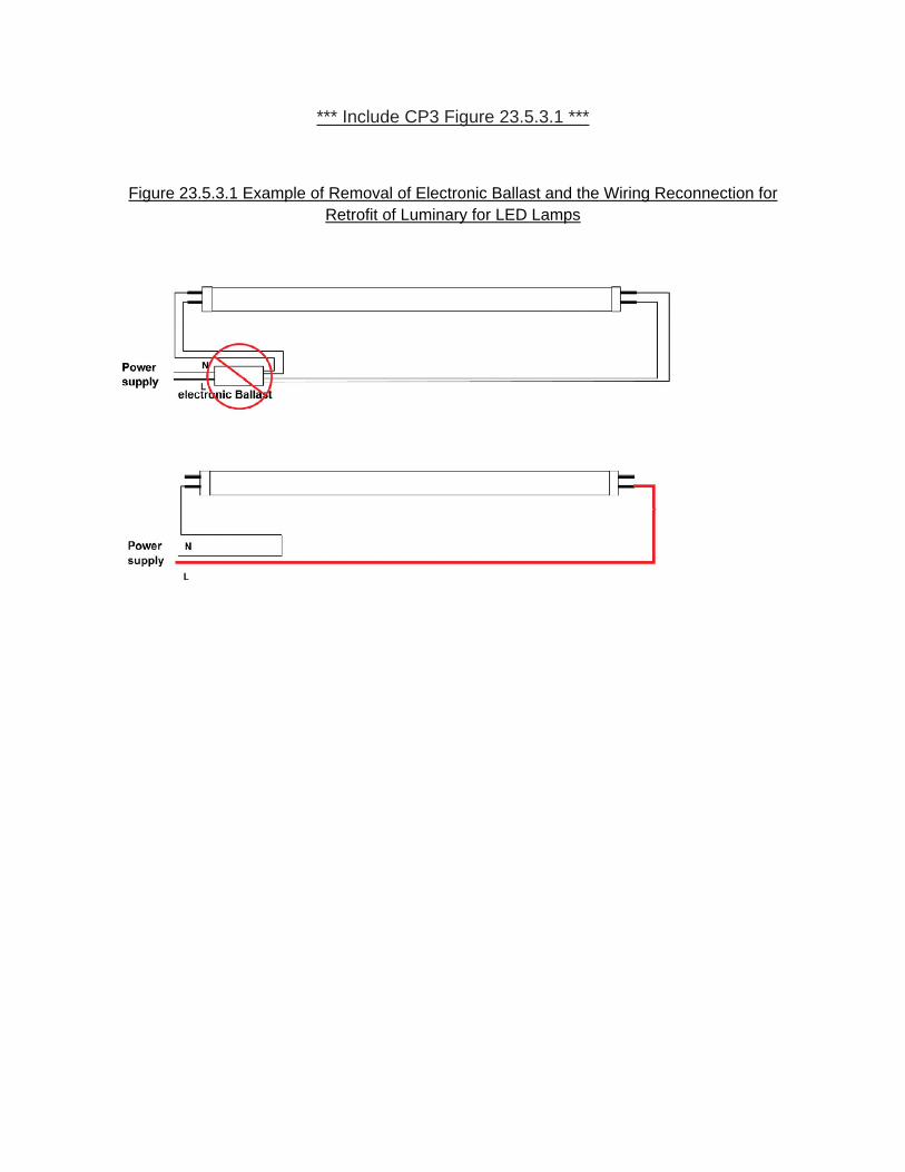
*** Include CP3 Figure 23.5.3.1 ***
Figure 23.5.3.1 Example of Removal of Electronic Ballast and the Wiring Reconnection for Retrofit of Luminary for LED Lamps


Report on Proposals – November 2012 NFPA 70Binstructions specify that line and neutral power are to be connected to the same lampholder, since this may result in apotential fire or electric shock hazard. Contact the LED luminaire retrofit kit manufacturer when in doubt about thecompatibility of the kit and the lamp fixture.23.5.3.2.3 Push-in terminals of existing fluorescent lampholders are not intended to have wires removed andreinstalled. If rewiring and/or connections to existing fluorescent lampholders are indicated by the installationinstructions, the connections may be made by splicing the lampholder leads using an appropriate splicing means usingListed connectors.
Newer lighting technologies that are more efficient are available. LED Lamps are one such technologywhose use in increasing. In particular, retrofitting existing luminaires with such needed to be addressed.
Affirmative: 141 Wyman, B.
66Printed on 10/31/2011
Report on Proposals – November 2012 NFPA 70B_______________________________________________________________________________________________70B-79 Log #CP5 EEM-AAA
_______________________________________________________________________________________________Technical Committee on Electrical Equipment Maintenance,
Revise Chapter 29 as follows:
29.129.1.1 Dependable performance and long service life of power tools is becoming more important as the need formechanization and the use of power tools increase. A plant’s entire inventory of portable tools can be kept in topoperating condition for maximum production quality and cost efficiency with planned routine and periodicinspection.29.1.2 There are many and varied types of portable power tools and many and varied causes of power tool failure.Therefore, the procedures for their maintenance can be general recommendations only. Variations exist and depend onthe type of tool and the particular conditions of its use. It is strongly recommended that the iInformation on proper useand maintenance given in the tool manufacturer’s use and care manual, supplied with each tool, should be carefullyfollowed.29.1.3 Periodic electrical testing will uncover many operating defects, and their immediate correction will ensure safeoperation and prevent breakdown and more costly repairs. This testing and the related maintenance should besystematic. A visual inspection is recommended before and after each use; when the tool is issued and again when it isreturned to the tool crib. Tools should be visually inspected for damage and defects before and after each use.29.1.4 Use tools only for their intended purpose.29.1.5 Use the personal protective equipment necessary when using tools to protect from the hazards of falling, flying,abrasive and splashing objects and from harmful dusts, fumes, mists, vapors or gases.29.1.6 Defective tools should immediately be tagged, removed from service, and reported.29.229.2.1 Employee training in the proper care and use of portable power tools is an important part of preventivemaintenance. Employees should be given instructions in selecting the proper tool for the job and the limitations of thetool. Using an underpowered tool for the work load can cause overloading. Employee training in the proper care anduse of portable power tools is an important part of preventive maintenance. Employees should be given instructions inselecting the proper tool for the job and the limitations of the tool. Using an underpowered tool for the work load cancause overloading.29.2.2 Employees should be trained to recognize obvious defects such as cut, frayed, spliced or broken cords; crackedor broken attachment plugs and missing or deformed grounding prongs. Such defects should be reported immediately.29.2.3 Employees should be instructed to report all shocks immediately, no matter how minor, and to cease using thetool. Tools that cause shocks should be examined and repaired before further use.29.3 . The maintenance procedures in 29.3.1 through 29.3.3.2 are general recommendations. Thebest source for maintenance information is theoriginal manufacturer.29.3.1 . Brushes and commutators should be inspected periodically. This iseasily accomplished by removal of brush-holder plugs or inspection plates, depending on the construction of the tool.Brushes worn down to 50 percent of their original size should be replaced. When a brush is replaced, always be sure touse the manufacturer’s original equipment.29.3.2 . All universal motors are fan ventilated to prevent excessive heat. Even thoughmany tools have filters and deflectors to prevent destructive material from damaging the motor, a small amount of it willpass through. Excessive buildup affects the brush operation and reduces the air volume necessary to cool the motor.When necessary, the tool should be blown out with low-pressure, dry-compressed air when used in a normalenvironment. More frequent specialized maintenance should be considered if the atmosphere is heavy in abrasives orconducting dusts.29.3.3 . Lubricant inspection is recommended at frequent intervals to ensuresufficient lubricant to prevent wear to mechanical parts. Dirty lubricants should be removed and replaced. Becauselubricant varies from tool to tool, it is recommended that proper lubricant be obtained from the manufacturer or themanufacturer’s distribution outlet.29.3.3.1 . Manufacturers carefully match lubricants to be compatible with speeds, heat, seals, bearings, andpressure to ensure long gear and mechanism life. Substitutions can damage the tool and invalidate the warranty.29.3.3.2 The wrong amount of lubricant can cause serious problems. Too little means that surfaces are not adequately
67Printed on 10/31/2011

Report on Proposals – November 2012 NFPA 70Bcovered and excess wear will result. Too much lubricant can cause excess pressure in the gear case and eventuallyruins seals.29.4 .29.4.1 The cord of an electric power tool is the lifeline It should be kept free of oil, grease, and other material that mightruin the rubber cover. Tangling knots or dragging across sharp surfaces should be avoided. The cord should not beused as a towline to carry or drag the tool.29.4.2 All power tools, unless they are double insulated and so marked, are required to be grounded through anadditional grounding conductor in the cord and the grounding prong of the attachment plug. The integrity of thisgrounding circuit is necessary for the protection of life and should be inspected visually before each use. Experience hasshown that the grounding prongs of attachment caps are frequently cut off for use in ungrounded receptacles. Thispractice should not be permitted.29.4.3 If a cord is cut, broken, spliced, or frayed; the attachment plug is damaged; or the grounding prong is removed, itshould be immediately withdrawn from service until it can be repaired. Cords can be replaced in their entirety, or adamaged cord can be repaired by cutting out the damaged portion and applying a plug and connector to rejoin the twosections. Replacement cords should be of the same type and conductor size and suitable for use.29.4.4 To avoid accidents, the green insulated conductor is to be used only for connecting the frame of the tool to theequipment-grounding terminal of the attachment plug meeting the conditions of NFPA 70, National Electrical Code,Section 400.24. It should not be used for any other purpose.29.4.5 Flexible cords and cables should be protected from damage. Contact with sharp corners and projections shouldbe avoided.29.5 .29.5.1 Before placing extension cords in service, the plug and connector should be checked for proper polarity, and thegrounding conductor should be tested for continuity and integrity. Extension cords of the proper conductor size shouldbe used to avoid excessive voltage drop that might result in poor operation and possible damage to the tool. Table 29.5lists the recommended sizes of extension cords.29.5.2 Only extension cords with an equipment grounding conductor should be used.29.5.3 Extension cords should be protected from damage, and not run through doorways or windows where the doorsor windows may close, causing damage to the cord.29.6 . Major overhauls and repairs should be performed by the manufacturer; however, largecompanies that use power tools and who prefer to do their own repairs and overhaul should obtain the necessary parts,schematics, connection diagrams, lubricant charts, and other technical information from the manufacturer.29.7 . Portable and cord-connected equipment should be tested periodically for the amount ofleakage current present to help ensure against shock hazards
The committee revised Chapter 29 to improve the readability of the document as well as to provideadditional safety practices specific to portable electrical tools.
Affirmative: 141 Wyman, B.
68Printed on 10/31/2011

Report on Proposals – November 2012 NFPA 70B_______________________________________________________________________________________________70B-80 Log #CP18 EEM-AAA
_______________________________________________________________________________________________Technical Committee on Electrical Equipment Maintenance,
Add a new Chapter 32 and delete 6.9.3 except for title directing to new Chapter 32:
*** Included CP 18 Chapter 32 (New) ****
An evaluation should be conducted by persons qualified for determining the condition of the equipment and anydamage that would preclude re-energization of electrical systems.
Process for restoration of electrical systems and equipment.(1) Proper safety procedures should be determined and Personal Protection Equipment (PPE) utilized beforecommencing restoration of the electrical systems and equipment.(2) Visual inspection for any contaminants and/or physical damage.(3) Where no damage is observed, next determine the electrical integrity of equipment by conducting applicable testing,such as continuity testing and insulation resistance.(4) Where equipment is damaged or has failed electrical integrity test(s), then determine which of following areapplicable, factoring in the time and criticality of getting theequipment back in service:(a) An appropriate, expedient repair, such as simply removing debris and other contaminants in the area and/orequipment without compromising safe operation of the equipment.(b) Repair per manufacturer’s instructions.(c) Locate replacement equipment and properly replace in accordance with manufacturer’s instructions.(5) Where equipment passes electrical integrity testing, a qualified person evaluates the risk of re-energizing electricalcables, panelboards, switchboards and switchgear.Data should be compared against baseline and recent maintenance test data.(6) Where the risk is determined to be acceptable, proceed to system level testing, such as detailed in Figure H.35 inAnnex H.(7) Once the system has been re-energized, a period of monitoring should be established providing confidence levels inthe restored system and/or equipment
A more detailed coverage of the maintenance tasks related to pre- and post-emergency actions iscovered in this proposal. A less comprehensive coverage of the maintenance tasks was previously covered in Chapter6.9.3, which has been deleted in this proposal. All of those original concepts are included here in more detail, as well asadditional relevant materials.
Affirmative: 141 Wyman, B.
WHITE, J.: This newly-expanded section provides added guidance on disaster recovery, which has been shown to bea critical component in resuming production and re-establishing a safe work place.
69Printed on 10/31/2011

1 NFPA 70B Log #CP18 Rec F2012 ROP
Chapter 32 Electrical Disaster Recovery 32.1 Introduction. When industrial facilities are faced with a catastrophic event such as a fire, flooding, hurricane, tornado, earthquake or similar disaster, a very specific and detailed sequence of events must occur to return the facility to productive operation in a safe and expeditious manner. To accomplish this after a disaster event, it is especially critical to analyze and repair the electrical power system in a safe and logical sequence. This chapter describes the recovery steps for an electrical power system and related equipment that should be followed after an electrical disaster event occurs. 32.2 Catastrophic event categories. The events surrounding a disaster can be detailed into specific event phases, categorized as: 32.2.1 The initial event. Disaster recovery efforts can be a result of fire, flooding, hurricane, tornados, and earthquakes. Disaster scenarios inflict damage of varying degrees to facilities such as but not limited to a result of the following: (1) Fire: soot, material and equipment damage, water damage, structural damage. (2) Flooding: water damage, structural damage. (3) Hurricane: water damage, structural damage, utility infrastructure damage. (4) Tornado: water damage, structural damage, utility infrastructure damage. (5) Earthquake: structural damage, utility infrastructure damage. 32.2.2 Securing the facility to limit damage. If possible, a facility should be secured prior to the disaster event to limit electrical and mechanical damage to equipment and systems. Electrical and mechanical systems should be shut down and secured, and critical components should be removed or preserved. Examples of tasks to limit damage: (1) Remove critical motors from their base and raise them above the flood line. (2) De-energize power to prevent electrical short circuit and arcing damage. (3) Secure storage tanks and other large devices that may float away. (4) Sandbag the fronts of electrical equipment rooms to limit water and debris entry. (5) Remove critical computer and electronic equipment from the site. (6) Remove all electrical equipment and supplies stored at ground level. 32.2.3 Mobilization of recovery personnel. During large-scale disaster events one of the biggest challenges for a commercial or industrial facility is providing enough qualified contractors and disaster recovery specialists to perform required remediation to the facility. Prior to a disaster event occurring, a preplan should be developed for the mobilization of recovery personnel. 32.2.3.1 In-house personnel. Before a disaster event occurs responsible personnel for the disaster recovery operations and facility repair should be designated and have possession of any
2 NFPA 70B Log #CP18 Rec F2012 ROP
applicable action plans. Depending on the magnitude of the event the recovery effort may be done solely with in-house personnel or with the assistance of professional restoration companies. 32.2.3.2 Outsourced (contract) personnel. Prior to a disaster event facilities should have considered establishing Master Service Agreements (MSA’s) with multiple qualified vendors who specialize in electrical disaster recovery services. Doing so prevents confusion and delays in the recovery efforts. Decide who will perform the cleanup (debris removal and electrical equipment restoration) and supply support equipment (such as flood pumps, heavy equipment and operators, emergency power equipment, temporary electrical services). Qualified repair facilities should be identified prior to a disaster recovery event. 32.2.3.3 Notification to insurance carrier. As soon as feasible the site insurance carrier’s claims representative should be notified of the event. 32.2.4 Developing a safety plan. A site specific safety plan should be developed before a disaster occurs. When performing recovery of electrical equipment, safety, environmental and health are paramount. Lockout/tagout, test before touch, and the application of safety grounds are typically covered in site electrical safety plans. While these are key safety aspects of placing equipment into an electrically-safe condition, there are other items of safety that need to be addressed and integrated into the safety plan such as: (1) Air quality. (2) Structural issues. (3) Chemical spill exposure. (4) Site-specific hazards. (5) Site-specific PPE requirements 32.2.5 Temporary and emergency power generation. When disaster events occur often times there is a loss of normal utility power. This creates a unique safety and logistical challenge to provide the required electrical power in a facility for critical systems and lighting. If the temporary power portion of the project is managed properly, the risk of accidental shock and burn can be drastically reduced. There should be dedicated personnel responsible for temporary power and they should develop all written standards and procedures to be followed. Typical emergency power procedures should identify elements such as: (1) Backfeeding of equipment. (2) Individual motor starters for pumps. (3) Temporary signage and barricades. (4) Site generator location maps. (5) Fueling schedules. (6) Written form for the addition of electrical power. (7) Access and exhaust flow. 32.2.6 Initial damage assessment. One of the first tasks in assessing equipment and system damage to electrical equipment involved in a disaster event is to gather all pertinent drawings

3 NFPA 70B Log #CP18 Rec F2012 ROP
and documentation available and perform a walkthrough and initial assessment of the entire electrical infrastructure. 32.2.6.1 Drawings, schematics, equipment documentation. In some instances drawings and documentation are not available due to destruction from the disaster event. All equipment instruction books, O&M manuals, and documentation should be identified and centrally located. 32.2.6.2 Priority assessment. Equipment repair priorities should be assessed with a focus on the highest priority equipment. Examples of typical equipment categories are: (1) Category 1 Medium-voltage equipment including distribution transformers. (2) Category 2 Low-voltage distribution equipment. (3) Category 3 Electric motors. (4) Category 4 Balance of the plant. 32.2.7 Documentation. All electrical components or equipment should be properly documented prior to removal to ensure the equipment is reinstalled properly. The documentation process includes: (1) Tag each piece of equipment. (2) Label all control and power wires. (3) Take a digital picture of each piece of equipment. (4) Sketch an accurate diagram of each piece of equipment on the electrical equipment drawing sheet. (5) Fill out the electrical equipment tracking form. (6) Save all pictures on a local database. (7) File the electrical equipment drawing sheet. (8) Create a master electrical equipment tracking document. (9) Shipping documents of all electrical equipment. 32.2.7.1 Service shop activities. If equipment is to be removed from the affected facility for repair at an offsite service center the equipment should be tagged, identified, tracked, and status updated on a master equipment repair database. 32.2.7.2 Equipment tag. Information on each tag should include a unique sequence number, plant identification number, plant description, date, power center or room number. The tag should be filled out with a medium point permanent marker so the information is legible. The tag should be attached to the equipment with a secure plastic wire tie. 32.2.7.3 Labeling of wires. All control wires should be labeled with wire numbers and the power wires with colored phasing tape. Make sure that each side of the termination, both wire and connected device, is identified. This will ensure the wiring will be re-connected as it was originally installed. 32.2.7.4 Photographs of equipment. After the equipment is tagged and the wires are labeled, a minimum of three photographs should be taken of each piece of equipment. The first photo

4 NFPA 70B Log #CP18 Rec F2012 ROP
should include the equipment tag in the picture, making sure the tag is legible and the picture is clear. The second photo is an overall view for the sole purpose of wire clarification/documentation during the reinstallation process and should include all wiring associated with the applicable device. The third photograph should be of the equipment nameplate. Additional photographs should be taken as deemed appropriate. 32.2.7.5 Field sketch. An accurate field sketch of the electrical equipment should be generated. The sketch should be recorded on a site specific electrical equipment drawing sheet template. This drawing sheet should include the job name, job number, power center, sequence number, plant equipment number, plant description, technician name, date and enough room to sketch the piece of equipment.
32.2.7.6 Equipment tracking sheet. After a sketch is made of the piece of equipment the equipment should be added to an electrical equipment tracking sheet. The electrical equipment tracking sheet should be customized and detailed. The tracking sheet should include general information such as overall condition, item number, sequence number, priority, area of the plant, power center or room number, transformer, substation, cell position, equipment type, circuit identification, plant identification number, manufacturer, percent water level, model number, frame size and voltage. Field tracking information should also include date documented, date pulled, date shipped, date returned, date installed and any dates that quality assurance procedures were performed. 32.2.7.7 Repair or replace. During the documentation process, initial decisions should be made pertaining to each piece of equipment that is damaged. Seeking the services of qualified equipment assessment personnel, whether manufacturer representatives or subject matter experts, is important in the decision making process. 32.2.7.7.1 Repair or replace decisions. Many factors can affect the repair/replace decision. Some of the likely decisions are: (1) Can the equipment be repaired or does the equipment need to be replaced? (2) Can the repairs take place on site or does the equipment need to be sent to a repair facility? 32.2.7.7.2 Repair or replace factors. Some of the factors that may affect the repair or replace decision: (1) Is the equipment currently manufactured? (2) Are there long lead times to replace with new? (3) Will equipment performance be compromised if repaired? (4) What is the age of the equipment? (5) What is the reliability requirement? (6) Can it be effectively repaired? (7) Is the manufacturer still in business? (8) Is the repair contractor qualified for the task? (9) Will the AHJ allow repair or replacement?
5 NFPA 70B Log #CP18 Rec F2012 ROP
(10) What is the financial impact? (11) What is the total outage time required? 32.2.8 Industry standards and guidelines. Industry standards and guidelines should be referred to for information. Information is available from: (1) Electrical Apparatus Service Association (EASA) ANSI/EASA AR100, Recommended Practice for the Repair of Rotating Electrical Apparatus (2) Federal Emergency Management Agency (FEMA) FEMA P-348, Protecting Building Utilities From Flood Damage; Principles and Practices for the Design and Construction of Flood Resistant Building Utility Systems (3) Institute of Electrical and Electronic Engineers (IEEE) IEEE Std. 3007.2, Recommended Practice for the Maintenance of Industrial and Commercial Power Systems (4) National Electrical Manufacturers Association (NEMA) NEMA Guidelines for Handling Water-Damaged Electrical Equipment
(5) InterNational Electrical Testing Association (NETA) ANSI/NETA Acceptance Testing Specification, Standard for Maintenance Testing Specifications for Electrical Power Distribution Equipment and Systems (6) National Fire Protection Association (NFPA) NFPA 70, National Electrical Code NFPA 70E, Standard for Electrical Safety in the Workplace (7) PowerTest Annual Technical Conference, 2009 Flood Repair of Electrical Equipment; March 12, 2009, Pat Beisert, Shermco Industries 32.2.9 Medium-voltage equipment. Medium-voltage equipment typically serves as the backbone to the electrical power system and should be the primary focus of the initial recovery activities. 32.2.10 Low-voltage distribution equipment. Affected components of low-voltage equipment should be removed to facilitate cleaning and drying of the structures. During the removal of the equipment care should be taken to keep all wiring for each component well marked and together. 32.2.11 Electric motors. When a disaster event involves water, electric motor repair is a major component of a flood recovery project. The documentation process is very similar to other electrical equipment but there are additional items that should be documented. The documentation process should include: (1) Nameplate data and location of the motor. (2) Tag the motor base and the motor with a unique sequence number.

6 NFPA 70B Log #CP18 Rec F2012 ROP
(3) Mark and record electrical connections. (4) Record coupling information and condition of coupling. (5) Mark and record shim information. (6) Collect all mounting hardware, couplings, shims and store in its own labeled container. This equipment stays on site and should be stored in a central location. 32.2.12 Power and control wiring. Power and control wiring should be tested to determine serviceability. See 11.21 Cables. 32.2.13 Balance of plant electrical repair. Balance of plant consists of all equipment other than medium-voltage equipment, low-voltage distribution equipment and motors. This includes items such as receptacles, light switches, lighting transformers, panelboards, start-stop stations, fire alarm panels, instrumentation and process control components, and metering. These devices are typically repaired by replacement. 32.2.14 Re-energization of the facility. Initial re-energization to utility power of a facility damaged by a disaster event should be carefully planned and methodically implemented. To reduce the possibility of accidental energization of equipment it may be prudent to forego any utility energization until all affected equipment has been repaired or replaced. 32.2.15 System commissioning. After re-energization of the facility the equipment operation and performance should be verified. See Chapter 31, EPM from Commissioning (Acceptance Testing) Through Maintenance and Figure H.35 in Annex H. A period of monitoring should be established to verify and document proper operation has been restored. 32.2.16 Project summary. After a disaster recovery event there is information gathered that should be available for future reference. The final project report should contain this data and should include information such as: (1) As found conditions of the electrical infrastructure. (2) Listing of equipment repaired or replaced. (3) Test results of all equipment tested. (4) Assessment of individual equipment condition. (5) Long-term equipment replacement plan.
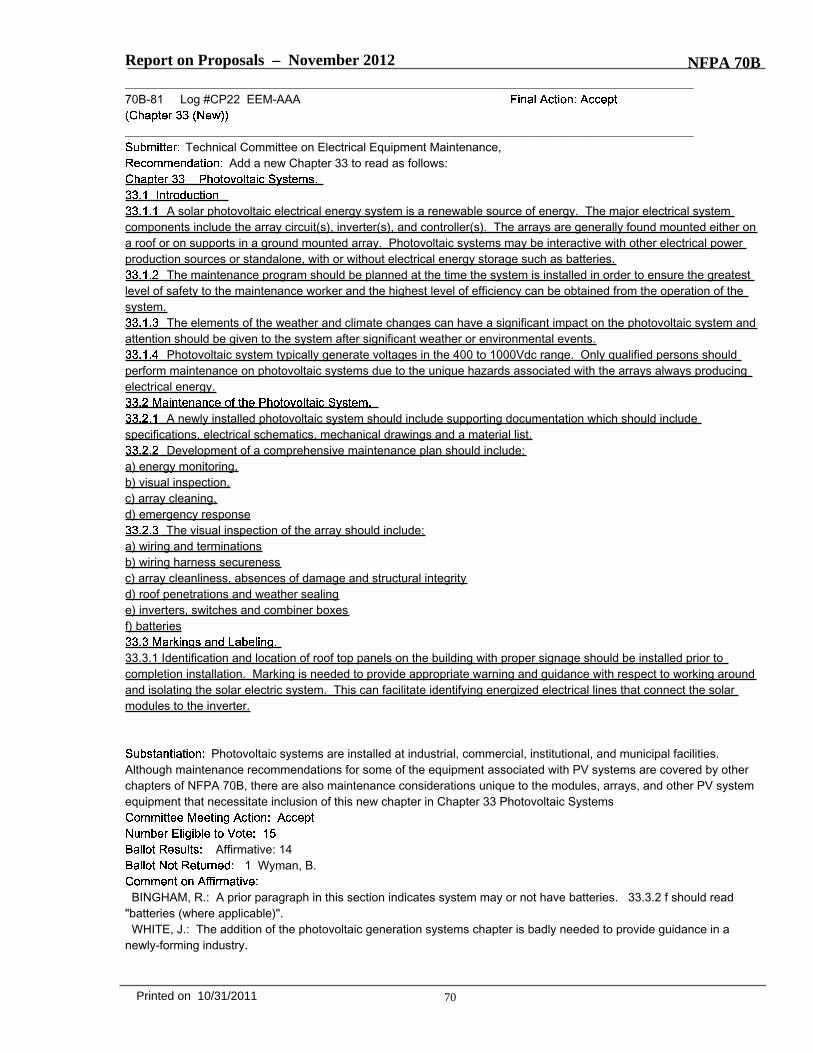
Report on Proposals – November 2012 NFPA 70B_______________________________________________________________________________________________70B-81 Log #CP22 EEM-AAA
_______________________________________________________________________________________________Technical Committee on Electrical Equipment Maintenance,
Add a new Chapter 33 to read as follows:
A solar photovoltaic electrical energy system is a renewable source of energy. The major electrical systemcomponents include the array circuit(s), inverter(s), and controller(s). The arrays are generally found mounted either ona roof or on supports in a ground mounted array. Photovoltaic systems may be interactive with other electrical powerproduction sources or standalone, with or without electrical energy storage such as batteries.
The maintenance program should be planned at the time the system is installed in order to ensure the greatestlevel of safety to the maintenance worker and the highest level of efficiency can be obtained from the operation of thesystem.
The elements of the weather and climate changes can have a significant impact on the photovoltaic system andattention should be given to the system after significant weather or environmental events.
Photovoltaic system typically generate voltages in the 400 to 1000Vdc range. Only qualified persons shouldperform maintenance on photovoltaic systems due to the unique hazards associated with the arrays always producingelectrical energy.
A newly installed photovoltaic system should include supporting documentation which should includespecifications, electrical schematics, mechanical drawings and a material list.
Development of a comprehensive maintenance plan should include:a) energy monitoring,b) visual inspection,c) array cleaning,d) emergency response
The visual inspection of the array should include:a) wiring and terminationsb) wiring harness securenessc) array cleanliness, absences of damage and structural integrityd) roof penetrations and weather sealinge) inverters, switches and combiner boxesf) batteries
33.3.1 Identification and location of roof top panels on the building with proper signage should be installed prior tocompletion installation. Marking is needed to provide appropriate warning and guidance with respect to working aroundand isolating the solar electric system. This can facilitate identifying energized electrical lines that connect the solarmodules to the inverter.
Photovoltaic systems are installed at industrial, commercial, institutional, and municipal facilities.Although maintenance recommendations for some of the equipment associated with PV systems are covered by otherchapters of NFPA 70B, there are also maintenance considerations unique to the modules, arrays, and other PV systemequipment that necessitate inclusion of this new chapter in Chapter 33 Photovoltaic Systems
Affirmative: 141 Wyman, B.
BINGHAM, R.: A prior paragraph in this section indicates system may or not have batteries. 33.3.2 f should read"batteries (where applicable)".WHITE, J.: The addition of the photovoltaic generation systems chapter is badly needed to provide guidance in a
newly-forming industry.
70Printed on 10/31/2011
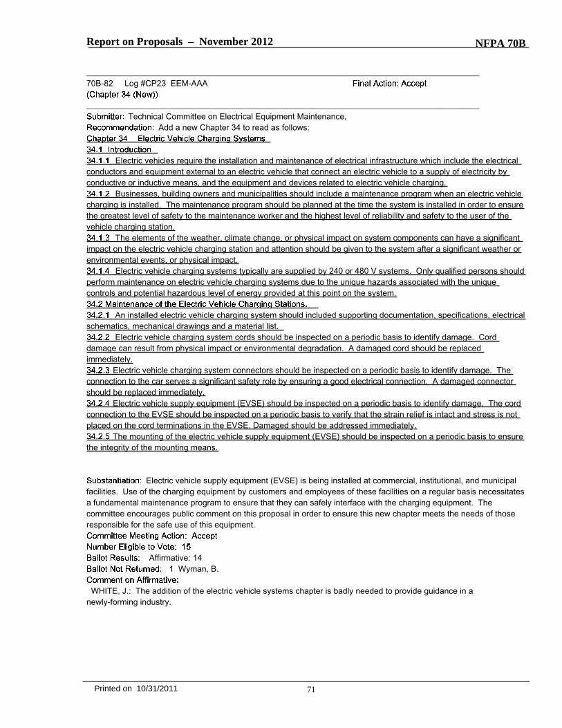
Report on Proposals – November 2012 NFPA 70B
_______________________________________________________________________________________________70B-82 Log #CP23 EEM-AAA
_______________________________________________________________________________________________Technical Committee on Electrical Equipment Maintenance,
Add a new Chapter 34 to read as follows:
Electric vehicles require the installation and maintenance of electrical infrastructure which include the electricalconductors and equipment external to an electric vehicle that connect an electric vehicle to a supply of electricity byconductive or inductive means, and the equipment and devices related to electric vehicle charging.
Businesses, building owners and municipalities should include a maintenance program when an electric vehiclecharging is installed. The maintenance program should be planned at the time the system is installed in order to ensurethe greatest level of safety to the maintenance worker and the highest level of reliability and safety to the user of thevehicle charging station.
The elements of the weather, climate change, or physical impact on system components can have a significantimpact on the electric vehicle charging station and attention should be given to the system after a significant weather orenvironmental events, or physical impact.
Electric vehicle charging systems typically are supplied by 240 or 480 V systems. Only qualified persons shouldperform maintenance on electric vehicle charging systems due to the unique hazards associated with the uniquecontrols and potential hazardous level of energy provided at this point on the system.
An installed electric vehicle charging system should included supporting documentation, specifications, electricalschematics, mechanical drawings and a material list.
Electric vehicle charging system cords should be inspected on a periodic basis to identify damage. Corddamage can result from physical impact or environmental degradation. A damaged cord should be replacedimmediately.
Electric vehicle charging system connectors should be inspected on a periodic basis to identify damage. Theconnection to the car serves a significant safety role by ensuring a good electrical connection. A damaged connectorshould be replaced immediately.
Electric vehicle supply equipment (EVSE) should be inspected on a periodic basis to identify damage. The cordconnection to the EVSE should be inspected on a periodic basis to verify that the strain relief is intact and stress is notplaced on the cord terminations in the EVSE. Damaged should be addressed immediately.
The mounting of the electric vehicle supply equipment (EVSE) should be inspected on a periodic basis to ensurethe integrity of the mounting means.
Electric vehicle supply equipment (EVSE) is being installed at commercial, institutional, and municipalfacilities. Use of the charging equipment by customers and employees of these facilities on a regular basis necessitatesa fundamental maintenance program to ensure that they can safely interface with the charging equipment. Thecommittee encourages public comment on this proposal in order to ensure this new chapter meets the needs of thoseresponsible for the safe use of this equipment.
Affirmative: 141 Wyman, B.
WHITE, J.: The addition of the electric vehicle systems chapter is badly needed to provide guidance in anewly-forming industry.
71Printed on 10/31/2011

Report on Proposals – November 2012 NFPA 70B_______________________________________________________________________________________________70B-83 Log #CP24 EEM-AAA
_______________________________________________________________________________________________Technical Committee on Electrical Equipment Maintenance,
Add new Chapter 35 to read as follows:
35.1.1 The electrical equipment associated with wind power electric systems requires maintenance attention that maybe more frequent than other installations due to the nature of these installations. Environmental conditions are often verysevere, vibration and temperature variations can affect the safety of these installations. Many different designs are usedand the technology is constantly changing.35.1.2 This service should be undertaken by trained and qualified workers and all electrical safety practices outlined inNFPA 70E need to be referenced and used.
35.2.1 Check tower grounding connections, cables and grounding electrode resistance, see Section 14.3.35.2.2 Check tower top electrical equipment, including navigational warning lighting, weather measurement devices.35.2.3 Special attention should be paid to lightning protection components and their associated wiring systems. SeeNFPA 780 for guidance in testing and maintenance of these systems.
Check electrical components and wiring for signs of damage or overheating.See Chapter 25, Sections 1-9
Check electrical components and wiring for signs of damage or overheating.Perform operational checks to ensure systems for emergency and safety
shut-down are functional.Perform connection and data transfer test to ensure
operation.Perform electrical inspections as specified in Chapter 21 for transformers and
Chapter 22 for converters.Perform electrical inspections as specified in Chapter 17 for circuit breakers
Inspect cable support systems, terminations, and cables fordamage due to vibration. See Section 19.2 for visual inspection, Terminations should be inspected as covered inSection 19.2.2 and tested per recommendations in Section 19.5.
Perform electrical inspections as specified in Chapter 15 for collectorsubstations and switchgear
35.12.l Check station power distribution panels for loose connections35.12.2 Check fire alarm and emergency lighting systems for correct operation and loose connections.35.12.3 Check motor control centers. See Sections 16.3, 16.4, and 16.7.
Wind power electric systems are installed at industrial, commercial, institutional, and municipal facilities.Although maintenance recommendations for some of the equipment associated with wind power systems are coveredby other chapters of NFPA 70B, there are also maintenance considerations unique to the turbines, towers and otherwind power system equipment that necessitate inclusion of this new chapter in NFPA 70B in order to ensure theongoing safe operation of these systems. The committee encourages public comment on this proposal in order toensure this new chapter meets the needs of those responsible for the safe use of this equipment.
Affirmative: 141 Wyman, B.
WHITE, J.: The addition of the wind generation systems chapter is badly needed to provide guidance in anewly-forming industry
72Printed on 10/31/2011

Report on Proposals – November 2012 NFPA 70B_______________________________________________________________________________________________70B-84 Log #CP12 EEM-AAA
_______________________________________________________________________________________________Technical Committee on Electrical Equipment Maintenance,
The only intended revisions to Annex C are the underlines and the strike-throughs:P.O. Box 12215, Research Triangle Park,
NC 27709.ANSI/AATCC-27, 1994 2009.
25 West 43rd Street, 4th Floor, New York, NY 10036.ANSI C2, , Part 1, Rules for the Installation and Maintenance of Electric Supply Stationsand Equipment, 1993 2007.
1220 L St. NW,Washington, DC 20005-4070.
, Chapter XIV, Electrical Systems.100 Barr Harbor Drive, P.O. Box C700,
West Conshohocken, PA 19428-2959.ASTM D 120, , 1995 2009.ANSI/ASTM D 664, 19952011.ASTM D 1048, 1999 2011.ASTM D 1049, , 1998 (E1-1995) (R2010).ASTM D 1050, , 1990 (E1 2005) (R-1999)ASTM D 1051, , 1995 2008.
P.O. Box 4999, Syracuse, NY 13221.Crouse-Hinds Code Digest,
1996 2011.1151 Boston- Providence Turnpike, Norwood, MA 02061.
, Chapter 32. 1968
445 Hoes Lane, P.O. Box 1331, Piscataway, NJ 08855-1331.ANSI/IEEE 56, 1977(Reaff. 1991).ANSI/IEEE 67, 1990 2005.ANSI/IEEE 80, 2000.ANSI/IEEE 141, (Red Book), 1993.ANSI/IEEE 142, (Green Book),1991.ANSI/IEEE 241, (Gray Book), 1990.ANSI/IEEE 242,(Buff Book), 1986 (Reaff. 1991) 2001.ANSI/IEEE 315 (ANSI Y32.2-75), 1975 (Reaff. 1993).ANSI/IEEE 400, 1991.ANSI/IEEE 432,1992.ANSI/IEEE 446,
(Orange Book), 1995.ANSI/IEEE 450,
1995 2010.ANSI/IEEE 519, 1992.IEEE 602, (White Book), 1996 2007.ANSI/IEEE 739, (Bronze Book),1995.IEEE C37.41,
1994
73Printed on 10/31/2011

Report on Proposals – November 2012 NFPA 70B
ANSI/IEEE C37.95, , 1989 (Reaff. 1994) 2002.ANSI/IEEE C37.96, 2000.IEEE C57.94,
1982 (Reaff. 1987).ANSI/IEEE C57.106, 1991 2006.IEEE C57.111,
1989.ANSI/IEEE C57.121,1998.
3 rue de Varembé, P.O. Box 131, 1211 Geneva 20,Switzerland.(In the United States, IEC Publications are available from American National Standards Institute, ANSI.)IEC No. 60417-DB-HS M and supplements, 1994 2008.
9800 Metcalf Avenue, P.O. Box 12901, Overland Park, KS 66282-2901.Magazine.
1221 Avenue of the Americas, New York, NY 10020.D. Beeman, .E. W. Boozer, .C. I. Hubert, .
3 Bethesda Metro Center, Suite 1100, Bethesda, MD 20814-5372.Index No. 2095.
1300 North 17th Street, Suite 1847, Rosslyn, VA22209.NEMA 280, (see Section 7, Field Test Devices, and Section 8,Field Troubleshooting), 1990.NEMA AB 3, (see Section 7, Maintenance and Field Testing), 19962006.NEMA AB 4,
, 1996 2009.NEMA ICS 1.3, , 1986 (Reaff. 1991 2009).NEMA ICS 2.3,
1995 (Reaff 2008).NEMA ICS 7, 1993 2006.ANSI/NEMA MG 2,
(see Section 2.17 8.3, Maintenance), 1989 (Reaff. 1999) 2001, (Rev 1-2007).NEMA PB 1.1,
1996 2007.NEMAPB 2.1,
1996 2007.4676 Columbia Parkway, Cincinnati, OH
45226.444 North Michigan Avenue, Chicago, IL 60611 1121 Spring Lake Drive,
Itasca, Ill 60143.NSC 129.46, .NSC 635, .
U.S. Army Corps of Engineers, 441 G Street NW, Washington, D.C.20314-1000.TM-5-682, November 1999.TM-5-683, November 1995.TM-5-684, November 1996.TM-5-685, August 1996.TM 5-686, November 1998.TM 5-688, November 1999.TM 5-691,
December 2000.
74Printed on 10/31/2011

Report on Proposals – November 2012 NFPA 70BTM 5-692-1,
April 2001.TM 5-692-2,
April 2001.Chemical
Rubber Co., 18901 Cranwood Parkway, Cleveland, OH 44128.E. P. Dutton & Co., 201 Park Avenue S., New York, NY 10003.Gale Research Co., 1400 Book Tower, Detroit, MI 48226.Hayden Book Co., Inc., 50 Essex Street, Rochelle Park, NJ 07662.National Fire Protection Association (NFPA), 1 Batterymarch Park, Quincy, MA 02169-7174.
, 1350 E. Touhy Avenue, Des Plaines, IL 60018.Prentice-Hall, Inc., Englewood Cliffs, NJ 07632.HowardW. Sams Co., Inc., 4300W. 62nd Street, Indianapolis, IN 46268.TAB Books, Blue Ridge Summit, PA 17214.Underwriters Laboratories Inc., 333 Pfingsten Road, Northbrook, IL 60062-2096.U.S. Government Printing Office, Superintendent of Documents, Mail Stop: SSOP,Washington, DC 20402-9328.Van Nostrand Reinhold Publishing Company, 135 W. 50th Street, New York, NY 10020Westinghouse Electric Corp., Printing Division, 1 Stewart Station Drive, Trafford, PA 15085.John Wiley & Sons, Inc., 605 Third Avenue, New York, NY 10016.C.2.2 Interruptions. IEEE 1159, Recommended Practice for Monitoring Electric Power Quality, 1995 2009.C.2.3IEEE 100, Standard Dictionary of Electrical and Electronic Terms, 1996.ANSI/IEEE 1100, (Emerald Book),1992 2005.C.2.4 Interruptions. IEEE 1159, Recommended Practice for Monitoring Electric Power Quality, 1995 2009.IEEE 1250, Guide for Service to Equipment Sensitive to Momentary Voltage Disturbances, 1995. IEEE Guide forIdentifying and Improving Voltage Quality in Power Systems, 2011.ANSI/NEMA C84.1, Electric Power Systems and Equipment, Voltage Ratings (60 Hertz), 1995 2006
Updated referenceso reflect current editions and titles.
Affirmative: 141 Wyman, B.
75Printed on 10/31/2011

Report on Proposals – November 2012 NFPA 70B_______________________________________________________________________________________________70B-85 Log #CP13 EEM-AAA
_______________________________________________________________________________________________Technical Committee on Electrical Equipment Maintenance,
The only intended revisions to Annex D are the underlines and the strike-throughs:D.1.1 NFPA Publications. National Fire Protection Association, 1 Batterymarch Park, Quincy, MA 02169-7471. NFPA70®, National Electrical Code®, 2008 2011 edition.D.1.2.1 ASTM Publications. ASTM International, 100 Barr Harbor Drive, P.O. Box C700, West Conshohocken, PA19428-2959.ASTM D 92, Standard Test Method for Flash and Fire Points by Cleveland Open Cup Tester, 2005a (R 2010).ASTM D 1933, Standard Specification for Nitrogen Gas as an Electrical Insulation Material, 1997 2003 (R 2008).D.1.2.2 IEEE Publications. Institute of Electrical and Electronics Engineers, 445 Hoes Lane, P.O. Box 1331, Piscataway,NJ 08855-1331.ANSI/IEEE 43, Recommended Practice for Testing Insulation Resistance of Rotating Machinery, 2000.IEEE 100, Authoritative Dictionary of IEEE Standards Terms, 2000.ANSI/IEEE 315 (ANSI Y32.2-75), Graphic Symbols for Electrical and Electronics Diagrams, 1975 (Reaff. 1993).ANSI/IEEE 1100, (Emerald Book),1992 2005.IEEE C57.12.00, General Requirements for Liquid-Immersed Distribution, Power, and Regulating Transformers, 20062010.D.1.2.3 NETA Publications. InterNational Electrical Testing Association, P.O. Box 687, Morrison, CO 80465.ANSI/NETA, Standard for Maintenance Testing Specifications for Electrical Power Distribution Equipment and Systems,2011.
Updated references to reflect current editions and titles.
Affirmative: 141 Wyman, B.
76Printed on 10/31/2011