7043 PP2147 EPG - metrotekaltyapi.com · orbis ™isarangeofconventionaldetectors...
16
optical detector multisensor detector heat detector mounting bases optical detector multisensor detector heat detector mounting bases product guide
-
Upload
nguyentuyen -
Category
Documents
-
view
239 -
download
0
Transcript of 7043 PP2147 EPG - metrotekaltyapi.com · orbis ™isarangeofconventionaldetectors...

optical detector
multisensor detector
heat detector
mounting bases
optical detector
multisensor detector
heat detector
mounting bases
product guide

orbis™ is a range of conventional detectorswhich has been developed and tested to createadvantages for fire engineers and installers, as wellas owners and users of buildings.
Orbis is a range with modern styling and a mountingbase that saves installation time. It is electricallycompatible with Apollo Series 60 and Series 65ranges of conventional detector (see Technical Data).
Orbis is a demonstration of Apollo’s commitment tothe market for high quality conventional detectors foruse in small to medium size installations. In developingthis range Apollo has put ease of installation andreliability in daily operation at the forefront ofconsiderations. The attractive and compact designmeans that Orbis will blend in well with allarchitectural styles.
Orbis is manufactured in Apollo’s factory nearPortsmouth, England
Orbis has been tested and approved to the followingstandards:
EN54–7: 2000 + A1: 2002optical smoke detectorEN 54–7: 2000 + A1: 2002 &CEA 4021: 1999-06multisensor smoke detectorEN 54–5: 2000 + A1: 2002heat detector
Detectors have been declared as beingcompliant with the essential requirementsof the EMC Directive 89/336/EEC and theConstruction Products Directive 89/106/EEC
Information in this guide is given in good faith, but Apollo FireDetectors cannot be held responsible for any omissions or errors.The company reserves the right to change specifications ofproducts at any time and without prior notice.
© Apollo Fire Detectors Limited 2004-2006
Contact points for
enquiries and help
Technical queries [email protected]
Resources [email protected](literature, photos)
Sales enquires [email protected]
Phone number for +44 (0)23 9249 2412all departments
Fax for all departments +44 (0)23 9249 2754
Website www.apollo-fire.co.uk
Assessed to ISO 9001: 2000Certificate number 010
...conventional detectors from Apollo
2

index
Contact points for enquiries and help 2Range of Products 4Features of Orbis™ 4Choosing a detector: questions and answers 4
Orbis optical smoke detector 6Where to use optical smoke detectors 6How does the Orbis optical detector work? 7Environmental performance 7Technical Data 7
Orbis multisensor smoke detector 8Where to use multisensor smoke detectors 8How does the Orbis multisensor detector work? 8Environmental performance 8Technical Data 9
Orbis heat detector 10Where to use heat detectors 10Choosing the correct class of heat detector 10How do Orbis heat detectors work? 11Environmental performance 11Technical Data 11
Orbis TimeSaver Base® 12Installing Orbis 12Fitting Orbis detector heads 13Orbis Features—LED Status 13
Relay Base 14Sav-Wire Base 14Orbis Adaptor 14Commissioning made easy 14StartUp 14What StartUp indicates 14FasTest® 14Smoke or Heat Testing 15
Maintenance and Servicing 15DirtAlert 15
3

Choosing a detector:questions and answers
The Orbis range does not include an ionisationsmoke detector. Are ionisation detectors redundant?
Ionisation detectors have been used for many yearsas extremely reliable smoke detectors. They havetraditionally been recommended for use where thefire risk is likely to include very small-particle smoke.
Standards such as EN54 recommend both ionisationand optical detectors as good general purpose smokedetectors.
One reason why ionisation detectors have become lesspopular is that they are more sensitive to phenomenathat cause false alarms than optical detectors.
Any other reasons?Ionisation detectors use a tiny radioactive foil.Although they are entirely safe to use, ionisationdetectors are subject to strict regulations concerningtransport, storage and disposal. Thus it is becomingincreasingly difficult to use ionisation detectors.
Should I use optical detectors to detect smoke in allapplications?As stated, optical detectors have long been recommendedas good general purpose smoke detectors. Laboratorytests have been carried out to compare the performanceof optical detectors in the standard test fires describedin the European standard EN54.
The results of these tests are given in Fig 1. The graphshows the acceptable response in terms of smoke densitywhich is given as ‘m’ on the y axis. Detectors mustrespond before the end of test which is an ‘m’ = valueof 2. The performance of Orbis detectors is given as asolid line which shows how evenly the optical detectorsrespond to the test fires.
If detectors respond too quickly (the lower shadedportion of the graph) they may be too sensitive andhence likely to generate false alarms.
If detectors respond too slowly (the upper shaded portion)they are in danger of not changing to the alarm statebefore the end of test.
An even response in the centre is the ideal response.
Range of Products
Orbis comprises an optical smoke detector, amutisensor smoke detector, heat detectortypes A1R, A1S, A2S, BR, BS, CR and CS, astandard electronics-free base, a diode base,a relay base and a Sav-Wire base.
Features of Orbis™
Orbis incorporates entirely new designs, bothmechanical and electronic. The aim has beento increase the attractiveness of the detector, makeinstallation quicker, enhance the reliability ofdetection and reduce the incidence of falsealarms. Orbis features:
• modern styling
• TimeSaver Base® designed for fastinstallation and cable termination
• a wide voltage and operating temperatureranges
• StartUp™ for fast commissioning
• DustDefy™ housing which limits ingressof dirt into detector
• new optical sensor for high reliability andreduced false alarm incidence
• new multisensor smoke detector fordetecting fast-burning fires
• algorithms for transient rejection
• chamber designed to inhibit dirt penetrationand thus reduce false alarms
• automatic drift compensation withDirtAlert® warning
• FasTest® which reduces the time taken totest detectors
• optional flashing LED to indicate normaloperation
• SensAlert® which indicates that the detectoris not operating properly
4
Orbis features and part numbers may vary accordingto territory. Please refer to your price list ordistributor for individual part numbers.

When would I use a multisensor?Multisensor smoke detectors have a heat sensing elementwhich makes them more sensitive if a fire developsheat as well as smoke. This speeds up the response ofthe detector in certain fires where heat is generatedrapidly, for instance in test fire TF5, which is an open,flaming liquid fire in which n-heptane is burned.
Multisensor smoke detectors are recommended foropen flaming fire risks.
If there is any doubt as to whether an optical detectoror a multisensor smoke detector should be used it iswise to fit a multisensor smoke detector.
Where would there be a need to install heat detectors?Heat detectors should be used if it is not possible touse smoke detectors. This will be the case wherenormal industrial processes produce substances whichcould be mistaken for smoke by a smoke detector, eg,flour mills, textile mills or loading bays with diesel-engined vehicles.
The type of substance encountered here would causefrequent false alarms if smoke detectors were fitted, soa heat detector is used instead.
How are heat detectors classified?EN54 classifies heat detectors according to the ambienttemperature in which they will be working andaccording to whether they may be tested as ‘static’detectors (changing to alarm at a preset temperature)or ‘rate-of-rise’ (changing to alarm at a preset increaseof temperature).
Heat detectors may also be marketed without eitherclassification; but then the detection characteristicsare unknown.
All Orbis heat detectors are tested and classified aseither static or rate-of-rise.
So what is the best way to choose a heat detector?To make things easier we have produced a flow chartwhich is shown on page 10.
2.00
1.50
1.00
0.50
0.00TF2 TF3 TF4 TF5
Poor
Test Fires
Acceptablevalues
Opticaldensity(m value)
2.00
1.50
1.00
0.50
0.00Orbis Optical Orbis Multisensor
Poor
Test Fires
Too sensitive
Too sensitive
Acceptablevalues
Opticaldensity(m value)
Fig.1 Orbis Optical detector response to Test Fires
Fig.2 Comparisons of response between Orbis Optical & Multisensor
© Apollo Fire Detectors Limited 2004/JDR
© Apollo Fire Detectors Limited 2004/JDR
5
optical smoke detector
Where to use optical smoke
detectors
Optical smoke detectors have always been recognisedas good detectors for general use. They are regardedas particularly suitable for smouldering fires andescape routes.
The performance of Orbis optical detectors is good inblack as well as in white smoke. In this respect Orbisis different from traditional optical smoke detectorswhich perform far better in white smoke than in black.
Orbis optical detectors are also designed to reducesignificantly the incidence of false alarms throughover-sensitivity to transient phenomena.
Orbis optical detectors are recommended for use asgeneral purpose smoke detectors for early warning offire in most areas.
orbis optical smoke detector
The sensing technology in the Orbis optical smokedetector is significantly different in design from previousoptical detectors. A full description is given in thesection ‘How do orbis optical smoke detectors work?’but the advantages of this system and its associatedalgorithms are:
• improved sensitivity to black smoke
• compensation for slow changes in sensitivity
• extra confirmation of smoke before alarm signalgiven
The algorithms are used to verify signals from thesensing chamber, to filter out transients and to decidewhen the detector should change to the alarm state.
All this combines to increase detection reliability andreduce false alarms.
6

How does the orbis opticaldetector work?
Orbis operates on the well established light scatterprinciple. The remarkable optical design of the Orbisoptical smoke detector allows it to respond to a widespectrum of fires.
The sensing chamber of the Orbis optical smokedetector contains an optical sensor which measuresback-scattered light as well as the more usual forward-scattered light. Sensitivity to black smoke is greatlyimproved.
The detector is calibrated so that Orbis is highly reliablein detecting fires but is much less likely to generatefalse alarms than ionisation smoke detectors.
The stability of the detector–high reliability, low falsealarm rate–is further increased by the use of algorithmsto decide when the detector should change to thealarm state. This removes the likelihood of a detectorproducing an alarm as a result of smoke from smokingmaterials or from another non-fire source.
The sensing chamber has been designed to keep outdust and other airborne contaminants.
Environmental performance
Orbis optical detectors operate over a broad range ofvoltages at extremes of temperature. Thus the operatingvoltage is 8.5V to 33V at –40° to +70°C, a uniqueachievement for a conventional smoke detector.
Remote output LED (–)characteristic:1.2kΩ connected to negativesupply
MECHANICAL
Material:Detector and base moulded inwhite polycarbonate.
Alarm Indicator:Integral indicator with 360°visibility (See Table 1 on page13 for details of flash rate)
Dimensions and weight ofdetector:97mm diameter x 31mmheight, 75g
Dimensions and weight ofdetector in base:100mm diameter x 46mmheight, 135g
Environmental:Operating and storagetemperature–40°C to +70°C(no condensation or icing)
Humidity:0% to 98% relative humidity(no condensation)
Wind speed:Unaffected by wind
Atmospheric pressure:Insensitive to pressure
IP rating to EN 60529: 1992*:23D
Electromagnetic Compatibility:The detector meets therequirements of BS EN 50 081-1for emissions and BS EN50 130-4for susceptibility.
marked
*The IP rating is not arequirement of EN 54 sincesmoke detectors have to beopen in order to function.An IP rating is therefore notas significant as with otherelectrical products.
DETECTOR OPERATINGPRINCIPLES
Principle of detection:Photo-electric detection of lightscattered by smoke particlesover a wide range of angles.The optical arrangementcomprises an infra-red emitterwith a prism and a photo-diodeat 90° to the light beam witha wide field of view. Thedetector’s microprocessoruses algorithms to processthe sensor readings.
Sampling frequency:Once every 4 seconds
ELECTRICAL
Supply voltage:8.5—33V DC
Supply wiring:2 wires, polarity sensitive
Maximum polarity reversal:200ms
Power-up time:<20 seconds
Minimum ‘detector active’voltage: 6V
Switch-on surge current at 24V:120µA
Average quiescent current at24V:65µA
Alarm current:At 12 volts 20mAAt 24 volts 40mA
Alarm load:600Ω
Holding voltage:5–33V
Minimum holding current:8mA
Minimum voltage to lightalarm LED:5V
Alarm reset voltage:<1V
Alarm reset time:1 second
technical data
All data is supplied subject to change without notice.Specifications are given at 23°C and 50% relative humidityunless otherwise stated.
7
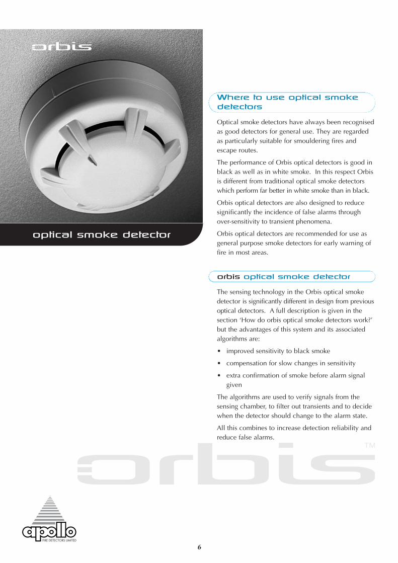
multisensor smoke detector
Where to use multisensor
smoke detectors
Multisensor smoke detectors are recognised as gooddetectors for general use but are additionally moresensitive to fast burning, flaming fires–including liquidfires–than optical detectors.
They can be readily used instead of optical smokedetectors but should be used as the detector of choicefor areas where the fire risk is likely to include heat atan early stage in the development of the fire.
As with Orbis optical smoke detectors the increasedreliability of detection is combined with high immunityto false alarms.
orbis multisensor smoke detector
The multisensor smoke detector is a thermallyenhanced smoke detector and as such will not give analarm from heat alone. It is a development of the Orbisoptical detector described in the previous chapter andgoes further in its capabilities of fire detection.
How does the orbis
multisensor detector work?
The optical sensor is identical to the one in the Orbisoptical detector. Its sensitivity is, however, influencedby a heat sensing element which makes the detectormore responsive to fast-burning, flaming fires.
It should be noted that the detector is a smoke detector.Although Orbis multsensor relies on both smoke andheat sensors it is not possible to switch from smokedetection to heat detection.
Environmental performance
The environmental performance of the multisensordetector is the same as that of the Orbis optical smokedetector.
8

Alarm reset time:1 second
Remote output LED (–)characteristic:1.2kΩ connected to negativesupply
MECHANICAL
Material:Detector and base moulded inwhite polycarbonate.
Alarm Indicator:Integral indicator with 360°visibility (See Table 1 onpage 13)
Dimensions and weight ofdetector:97mm diameter x 42mmheight, 80g
Dimensions and weight ofdetector in base:100mm diameter x 57mmheight, 140g
Environmental:Operating and storagetemperature–40°C to +70°C(no condensation or icing)
Humidity:0% to 98% relative humidity(no condensation)
Wind speed:Unaffected by wind
Atmospheric pressure:Insensitive to pressure
IP rating to EN 60529: 1992*:23D
Electromagnetic Compatibility:The detector meets therequirements of BS EN 50 081-1for emissions and BS EN50 130-4for susceptibility.
marked
*The IP rating is not arequirement of EN 54 sincesmoke detectors have to beopen in order to function.An IP rating is therefore notas significant as with otherelectrical products.
DETECTOR & OPERATINGPRINCIPLES
Principle of detection:Photo-electric detection of lightscattered by smoke particlesover a wide range of angles.The optical arrangementcomprises an infra-red emitterwith a prism and a photo-diodeat 90° to the light beam with awide field of view. The detector’smicroprocessor uses algorithmsto process the sensor readings.The heat sensing elementincreases the sensitivity of thedetector as the temperaturerises.
Sampling frequency:Once every 4 seconds
ELECTRICAL
Supply voltage:8.5—33V DC
Supply wiring:2 wires, polarity sensitive
Maximum polarity reversal:200ms
Power-up time:<20 seconds
Minimum ‘detector active’voltage: 6V
Switch-on surge current at 24V:120µA
Average quiescent current at24V:65µA
Alarm current:At 12 volts 20mAAt 24 volts 40mA
Alarm load:600Ω
Holding voltage:5–33V
Minimum holding current:8mA
Minimum voltage to lightalarm LED:5V
Alarm reset voltage:<1V
technical data
All data is supplied subject to change without notice.Specifications are given at 23°C and 50% relative humidityunless otherwise stated.
9

10
heat detector
Where to use heat detectors
Heat detectors are used in applications where smokedetectors are unsuitable. Smoke detectors are usedwherever possible since smoke detection providesearlier warning of fire than heat detection. There are,however, limits to the application of smoke detectorsand these are described in the section ‘Choosing adetector’ on page 4.
Heat detectors should be used if there is a danger ofnuisance alarms from smoke detectors.
orbis heat detector
The Orbis range incorporates six heat detector classesto suit a wide variety of operating conditions in whichsmoke detectors are unsuitable.
The European standard EN54-5:2000 classifies heatdetectors according to the highest ambient temperaturein which they can safely be used without risk of falsealarm. The classes are identified by the letters A to G.(Class A is subdivided into A1 and A2.) In addition tothe basic classification, detectors may be identified bya suffix to show that they are rate-of-rise (suffix R) orfixed temperature (suffix S) types.
All heat detectors in the Orbis range are tested as staticor rate-of-rise detectors and are classified as A1R,A1S, A2S, BR, BS, CR and CS.
Choosing the correct class of
heat detector
Heat detectors have a wide range of responsecharacteristics and the choice of the right type for aparticular application may not always seem straight-forward. It is helpful to understand the way that heatdetectors are classified as explained earlier and tomemorise a simple rule: use the most sensitive heatdetector available consistent with avoiding false alarms.
In the case of heat detectors it may be necessary totake an heuristic approach, ie, trial and error, until thebest solution for a particular site has been found. Theflowchart (Fig. 3) will assist in choosing the right classof heat detector.
Fig.3 Choosing a heat detector
© Apollo Fire Detectors Limited 2004-6/RHD

11
If the fire detection system is being designed to complywith BS 5839–1: 2002 heat detectors should beinstalled at heights of less than 12 metres with theexception of class A1 detectors, which can beinstalled at heights up to 13.5 metres.
How do orbis heat detectors
work?
Orbis heat detectors have an open-web casing whichallows air to flow freely across a thermistor whichmeasures the air temperature every 2 seconds. Amicroprocessor stores the temperatures and comparesthem with pre-set values to determine whether a fixedupper limit–the alarm level–has been reached.
In the case of rate-of-rise detectors the microprocessoruses algorithms to determine how fast the temperatureis increasing.
Static heat detectors respond only when a fixedtemperature has been reached. Rate-of-rise detectorsalso have a fixed upper limit but they also measure therate of increase in temperature. A fire might thus bedetected at an earlier stage than with a static detectorso that a rate-of-rise detector is to be preferred to astatic heat detector unless sharp increases of heat arepart of the normal environment in the area protectedby the heat detector.
Environmental performance
The environmental performance is similar to that ofthe Orbis optical smoke detector but it should benoted that heat detectors are designed to work atparticular ambient temperatures (see Fig 3).
MECHANICAL
Material:Detector and base moulded inwhite polycarbonate.
Alarm Indicator:Integral indicator with 360°visibility (See Table 1 on page13 for details of flash rate)
Dimensions and weight ofdetector:97mm diameter x 36mmheight, 70g
Dimensions and weight ofdetector in base:100mm diameter x 51mmheight, 130g
Environmental:Operating and storagetemperature–40°C to +70°C(no condensation or icing)
Humidity:0% to 98% relative humidity(no condensation)
Wind speed:Unaffected by wind
Atmospheric pressure:Insensitive to pressure
IP rating to EN 60529: 1992*:23D
Electromagnetic Compatibility:The detector meets therequirements of BS EN 50 081-1for emissions and BS EN50 130-4for susceptibility.
marked
*The IP rating is not arequirement of EN 54 sinceheat detectors have to be openin order to function. An IPrating is therefore not assignificant as with otherelectrical products
DETECTION OPERATINGPRINCIPLES
Principle of detection:Measurement of heat by meansof a thermistor.
Sampling frequency:Once every 2 seconds
ELECTRICAL
Supply voltage:8.5—33V DC
Supply wiring:2 wires, polarity sensitive
Maximum polarity reversal:200ms
Power-up time:<20 seconds
Minimum ‘detector active’voltage: 6V
Switch-on surge current at 24V:120µA
Average quiescent current at24V:65µA
Alarm current:At 12 volts 20mAAt 24 volts 40mA
Alarm load:600Ω
Holding voltage:5–33V
Minimum holding current:8mA
Minimum voltage to lightalarm LED:5V
Alarm reset voltage:<1V
Alarm reset time:1 second
Remote output LED (–)characteristic:1.2kΩ connected to negativesupply
technical data
All data is supplied subject to change without notice.Specifications are given at 23°C and 50% relative humidityunless otherwise stated.

TimeSaver Base®
installing orbis
Orbis has been designed to make installation fast andsimple. Fig 4 shows the TimeSaver mounting base asit is seen from the installer’s point of view.
The E-Z fit fixing holes are shaped to allow a simplethree-step mounting procedure:
• Fit two screws to the mounting box or surface• Place the Orbis base over the screws and slidehome
• Tighten the screws
The base offers two fixing centres at 51 and 60mm.
A guide on the base interior indicates the length ofcable to be stripped. Five terminals are provided forthe cables, four being grouped together for ease oftermination.
The terminals are:
• positive IN• positive OUT• negative IN and OUT (common terminal)• remote LED negative connection• functional earth (screen)
The terminal screws are captive screws and will notfall out of the terminals. The base is supplied with thescrews unscrewed in order to avoid unnecessary workfor the installer.
The end-of-line resistor or active device should beconnected between the OUT+ and COM– terminals.
If it is required that all detectors be fitted with their LEDsfacing the same direction the bases must be fitted to theceiling observing the marking on the exterior whichindicates the position of the LED.
The bases may be connected as shown in Fig 5 whereremote LEDs, if required, are connected to the associatedbase.
Fig 6 shows how to connect one remote LED to morethan one base so that an alarm in any of the detectorsconnected will switch the remote LED.
In many installationsbases with diodes arespecified in order thatan active end-of-linedevice may be fitted.Diode bases aremarked ‘OD’. © Apollo Fire Detectors Limited 2004/JDR
12

fitting orbis detector heads
When the bases have been installed and the systemwiring tested, the detector circuits can be populated.
Two methods are suggested:
1. Apply power and fit the detectors one by one,starting at the base nearest the panel and workingtowards the end of the circuit. As each detector ispowered up it will enter ‘StartUp’ and flash red (seenext page for a full description of this feature). Ifthe LED does not flash, check the wiring polarityon the base and ensure there is power across IN+and COM–. If the LED is flashing yellow the detectoris not operating correctly and may require maintenanceor replacing (see DirtAlert and SensAlert® belowand the section ‘Maintenance and servicing’ onpage 15).
2. Fit all detectors to the circuit, apply power andcheck detectors by observing the LED status of eachdevice. The StartUp feature lasts for 4 minutes so itmay be necessary to reset or de-power the circuit toallow all detectors to be observed. The LED status isthe same as method 1.
Feature Description of Feature Red LED Status Yellow LED Status
StartUp™ Confirms that the detectors are wired in the Flashes No Flashcorrect polarity once per second
FasTest® Maintenance procedure, takes just 4 seconds to functionally Flashes No Flashtest and confirm detectors are functioning correctly once per second
DirtAlert™ Shows that the drift compensation No Flash Flashes once per second inlimit has been reached StartUp (Stops flashing
when StartUp finishes)
SensAlert® Indicates that the sensor is not No Flash Flashes every 4 secondsoperating correctly (Flashes once per second in
StartUp)
Normal Operation At the end of StartUp and FasTest No Flash No Flash(without flashing LED as standard)
Flashing LED Detector’s red LED flashes in normal Flashes every No FlashVersion operation (at the end of FasTest) 4 seconds
LED—
COM—IN+
OUT+
Terminal 4, Screen
(Functional Earth)
Direction of LED indicated by
mark on outside of moulding
Snip along marked lines and
remove this part to lock the
detector to the base
OUT + LED —
IN & OUT —IN +
From control panel
Screen(FunctionalEarth)
From control panel
Screen(FunctionalEarth)
LED—
COM — IN +
OUT+
1
2 3
4
LED—
COM — IN +
OUT+
1
2 3
4
LED—
COM — IN +
OUT+
1
2 3
4
LED—
COM — IN +
OUT+
1
2 3
4
LED—
COM — IN +
OUT+
1
2 3
4
LED—
COM — IN +
OUT+
1
2 3
4
orbis features: LED status
Fig.6 3 bases wired with a common LED
Fig.5 Base wiring diagram
Fig.4 TimeSaverBase®
© Apollo Fire Detectors Limited 2004/JDR
© Apollo Fire Detectors Limited 2004/JDR
© Apollo Fire Detectors Limited 2004/JDR
13
Table 1

Orbis has been designed with a number of features thatmake commissioning easier and that save time.
StartUpWhen Orbis detectors are powered up they automaticallyenter a phase known as StartUp and in which they stayfor 4 minutes. After this they revert to normal operation.If the detector is reset, ie, if power is disconnected forone second or longer, the detector will always enterStartUp for the first four minutes after power has beenrestored. The detector LED flashes red once a second toindicate that it is in StartUp.
What StartUp indicatesStartUp is used to check that the positive and negativecables are connected in the correct polarity and thatpower has been applied to the detector. If this is thecase, the LED will flash red once a second.
StartUp will not check whether the IN+ and OUT+connections have been transposed. This is not a problemif standard bases are used as the detector will operatenormally.
If, however, diode bases are used and a detector isremoved from a base with transposed positiveconnections none of the detectors beyond this pointwill operate.
FasTest®Orbis detectors incorporate a test facility known asFasTest®.
In normal operation Orbis smoke detectors do notchange to the alarm state at the first sensing of smoke.If they did, they could be too sensitive and cause falsealarms. Algorithms determine the point at which thedetector changes to alarm.
This could slow down routine maintenance duringwhich detectors are tested by means of smoke or asmoke-simulating substance.
In order to avoid such a problem Orbis detectors haveFasTest, a facility which is automatically available duringStartUp and which modifies algorithms so that testing ispossible within 4 seconds.
LED—
COM — IN +
OU
T+
1
2 3
4
LED—
COM — IN +
OU
T+
1
2 3
4+
_To next detector
From control panel Screen
(Functional Earth)
Screen(Functional Earth)
COM COMN/C N/CN/O N/O
RELAYCONTROLLED
DEVICE
RELAYCONTROLLED
DEVICE
Fig.7 TimeSaver relay base wiring connections
© Apollo Fire Detectors Limited 2004/JDR
14
Relay BaseThe relay base incorporates a single-pole voltage-freechangeover contact for switching ancillary equipment.The maximum contact rating is 30V 1A.
When the detector changes to the alarm state, therelay is energised, causing the contact to change state.The contact will remain in this condition until thedetector is reset.
Sav-Wire BaseA base is available which allows Orbis detectors to beused in ‘Sav-Wire’ detection and alarm systems.
Orbis Adaptor
An adaptor can be used to enable Orbis detectors tobe fitted to Series 60/65 bases.
Commmissioningmade easy
Adaptor

The problem of testing is even more acute in the case ofheat detectors as they absorb a great deal of heat duringtesting. Orbis heat detectors also incorporate FasTest®.
In the case of heat detectors a fast test is defined as asample which recognises a rise of 10°C within oneminute. Since sampling takes place every 2 seconds anOrbis heat detector will respond within about 4seconds.
Smoke or Heat Testing
Smoke or heat testing Orbis detectors is aided by theFasTest® feature. A detector will react rapidly to the correctstimulus if applied within 4 minutes after power up.
Choose the appropriate test function on the controlpanel and reset the detector circuit. This should placethe detectors into FasTest®. Apply smoke or heat asappropriate and the detector should enter the alarmstate within 4 seconds. The panel may sound the alarmand reset the zone automatically (refer to control panel’sinstructions). If not, silence the alarm and reset thepanel. Repeat the procedure as necessary.
Note that the multisensor detector will respond to eithersmoke or heat while in FasTest®. It will not respond toheat only in normal operating mode.
15
Detectors should be checked regularly at the intervalsindicated by the locally applicable code of practice.Apollo recommends that detectors be checked at leastonce a year.
One of the features of Orbis is FasTest® which makes itpossible to carry out a functional test, using smoke orheat, within about four seconds. See page 14 for details.
If detectors appear not to be functioning correctly theyshould be returned to Apollo for testing.
If detectors are externally dirty they can be cleanedcarefully with a damp cloth using a small amount ofindustrial alcohol.
DirtAlert™Orbis detectors have drift compensation to compensatefor changes caused by the environment. The most usualchange is contamination.
If the detector is dirty to the point where it can nolonger compensate, its LED will flash yellow while itis in StartUp. Maintenance checks should thereforeinclude removing a detector from its base andre-inserting it or pressing reset on the panel to initateStartUp.
A flashing yellow LED is not a sign that the detectorneeds to be replaced immediately. The decision toreplace should be taken by the service engineer, takingthe environment of the detector into account. If thedetector is not replaced it will evenually cause falsealarms.
When deciding how long to leave the detector on site insuch a case, the following rule of thumb may be used:
installation time + 25%
For example, if a detector had been installed for fouryears when the LED flashed yellow, it could be left inplace for up to 12 months.
Dirty detectors can be returned to Apollo for cleaning andrecalibration
maintenance andservicing

PP2147/2006/Issue 2
36 Brookside Road, Havant, Hampshire PO9 1JR, England. Tel: +44 (0)23 9249 2412. Fax: +44 (0)23 9249 2754.Email: [email protected] Website: www.apollo-fire.co.uk
Assessed to ISO 9001: 2000Certificate number 010
© Apollo Fire Detectors Ltd 2003 - 2006