70 Amp AC/DC Current Probe - Pintek
40
DC‐1MHz (1mV=2mA at 500 mV/A) INSTRUCTION MANUAL 使 用 說 明 書 70 Amp AC/DC Current Probe 70 安培 交流/直流 電流探測鉗 PA-677
Transcript of 70 Amp AC/DC Current Probe - Pintek

DC‐1MHz (1mV=2mA at 500 mV/A)
INSTRUCTION MANUAL 使 用 說 明 書
70 Amp AC/DC Current Probe 70 安培 交流/直流 電流探測鉗
PA-677

1

2
TABLE OF CONTENTS General Safety Instructions------------------------------------------------- 4 Safety Terms and Symbols-------------------------------------------------- 5 Getting Started------------------------------------------------------------------6 Basic Operation-----------------------------------------------------------------8 Maintenance--------------------------------------------------------------------10 Specifications------------------------------------------------------------------13 Replaceable Parts-------------------------------------------------------------19 Accessories---------------------------------------------------------------------37
目 次
一般安全概述-----------------------------------------------------------------21 安全聲明及標誌--------------------------------------------------------------22 準備啟動------------------------------------------------------------------------23
基本操作------------------------------------------------------------------------25
保養-------------------------------------------------------------------------------28 規格-------------------------------------------------------------------------------30 可更換的零件-----------------------------------------------------------------36 附件-------------------------------------------------------------------------------37
3
PA-677
70 Amp AC/DC Current Probe

4
General Safety Instructions:
Read the following safety instructions to avoid injury and prevent damage to this product or any products connected to it. Use this product only as specified.
Only qualified personnel should perform service procedures.
To Avoid Fire or Personal Injury
Connect and Disconnect Properly. Connect the probe output to the measurement instrument before connecting the probe to the circuit under test. Disconnect the probe input and the probe ground from the circuit under test before disconnecting the probe from the measurement instrument.
Observe All Terminal Ratings. To avoid fire or shock hazard, observe all rating and markings on the product. Consult the instruction manual for further ratings information before making connections to the product.
Replace Batteries Properly. Replace batteries only with the proper type and rating specified.
Do Not Operate Without Covers. Do not operate this product without the covers or panels.
Avoid Exposed Circuitry. Do not touch exposed connections and components when power is present.
Do Not Operate With Suspected Failures. If you suspect there is damage to this product, have it inspected by qualified service personnel.
Do Not Operate in Wet/Damp Conditions.
Do Not Operate in an Explosive Atmosphere.
Keep Product Surfaces Clean and Dry.

5
Safety Terms and Symbols: Terms in This Manual. These terms may appear in this manual:
WARNING. Warning statements identify conditions or practices
that could result in injury or loss of life.
CAUTION. Caution statements identify conditions or practices
that could result in damage to this product or other property.
Terms on the Product. These terms may appear on the product:
DANGER indicates an injury hazard immediately accessible as you read the marking.
WARNING indicates an injury hazard not immediately accessible as you read the marking.
CAUTION indicates a hazard to property including the product.
Symbols on the Product. These symbols may appear on the product:
Attention refer to operation Instructions.
This instrument has double insulation.

6
Getting Started:
The PA-677 current probe enables a general purpose oscilloscope to display AC and DC current signals up to 140 amps Peak (50A RMS). The PA-677 current probe can also make AC and DC measurements with a multimeter by using the recommended accessory MT-246N (BNC-to-banana) plug adapter.
Figure 1: shows the controls and indicators on the PA-677 current probe.
Press Button Battery Inside (suggested outdoor using)
Max. 10.3 Wire
DC Zero Offset Range Selection (Power On/Off)
Output Into BP-250
AC Adaptor Input

7
Table 1: PA-677 controls and indicators
Control/Indicator Description
Current flow symbol. The arrow shows the probe’s polarity convention for measuring current flowing from positive to negative.
Zero adjustment. Rotate to adjust the probe output to zero when there is no current present. It may also be used to offset a DC signal component. Zeroing is not needed for AC measurements unless your instrument cannot isolate a DC component (if present).
OFF/Range switch. Slide the switch from OFF to either the 50 mV/A or 500mV/A range. When either range is selected, the probe is turned on, and the green battery indicator lights. If the indicator does not light, see Battery Notes and Battery Installation on page11.
Battery indicator. The green battery indicator lights when the probe is turned on. For more information, see Battery Notes and Battery Installation on page11.
Overload indicator. The red overload indicator lights if the measured signal is greater than the selected range capacity. Switch the probe to 50 mV/A if possible, or remove the probe from the circuit.

8
Basic Operation: Before using the probe, the batteries or specified power adaptor must be installed. See the battery installation instructions on page11.
WARNING!
Do not clamp the probe onto circuits with voltages greater than 600 VAC. Personal injury or damage to the probe may result.
Always connect the PA-677 current probe output to the instrument before clamping onto the circuit under test. 1. First connect the current probe BNC connector to BP-250 (double BNC
connection cable) then connect to oscilloscope input. Start by setting the oscilloscope voltage input channel to DC volts, and the voltage sensitivity scale to 0.1 V/div.
2. Move the OFF/ Range switch to the 50 mV/A or 500 mV/A position to turn on the probe.
(※The PA-677 current probe has a green LED power/battery indicator. If the LED does not light, replace the battery or use specified power adaptor.)
3. Use the ZERO adjustment to zero or offset the probe output detection of residual magnetic DC charges.
4. Connect the probe to the circuit by opening the jaws and clamping around the conductor. See Figure 2.
NOTE. Clamping around both the “hot” and neutral wires may give you a zero reading. (Remember to unclamp the probe from the conductor before disconnecting it from your meter or instrument).
Figure 2: Connecting the PA-677 current probe.

9
5. Adjust the probe channel and oscilloscope’s time base as necessary to get a clear and stable view of the signal. Set the oscilloscope input to DC volts to see both the AC and DC currents; set the channel to AC to see the AC current only.
The current drawn by different devices look much different than that of others. While the RMS current can only be used in low frequency current, the momentary peaks may be quite high. Figure 3 shows the difference between the line current drawn by a resistive load and a motor controller.
Figure 3: Typical current waveforms
Congratulations on your purchase of the PA-677, a multifunctional current probe. When connecting to a digital meter, use the recommended MT-246N (BNC-to-banana adapter). Connect the black lead to the meter COM (black letters on the meter), and the red lead to the VΩ input (red letters on the meter).
To measure only AC current, set the meter to measure AC volts.
To measure DC current, set the meter to measure DC volts. Note the current convention arrow on the probe to get the proper polarity reading.
To increase the measurement sensitivity of the PA-677 current probe, loop additional turns of the wire under test through the jaws. See Figure 4. The sensitivity of the PA-677 current probe is multiplied times the number of loops in the jaws. For example: 500 mV/A X 4 turns = 2000 mV/A.

10
Figure 4: Increasing the sensitivity
Maintenance: Use the information in this section to properly maintain the operation of your PA-677 AC/DC Current Probe.
1. Notes on Battery and Power Converter:
The PA-677 current probe uses a single square 9 V battery. This machine is a high power product. Please use the specified alkaline battery.
As the battery in the PA-677 current probe is drained, significant gain errors may occur. The green LED will continue to light until a low battery voltage of 6.5 V is reached.
If probe gain errors are detected, replace the battery with a fresh one.
As an alternative, an AC power converter can be used to avoid gain error due to poor battery durability. Switch to a square 9V battery only when there is no AC power supply available outdoors.
When using an AC power converter for an extended time, we suggest you remove the battery from the compartment. This is because heating will result in battery leakage, and battery electrolyte will rust the circuit board, thus creating major damage. Furthermore, batteries are high pollution products and therefore by reducing their usage, we will in turn protect the environment.

11
PA-677 has in its design a priority external power circuit therefore it is safe to simultaneously install the battery and the external power supply. During usage, removing the external power supply will not produce waveform anomaly or any damage. However when external power is used for an extended time (more than 1 week), removal of battery is recommended. This will avoid leakage of battery since the quality of the batteries is something that is out of our control. 2. Battery Installation:
(1) Remove the probe from the circuit.
(2) Please push and open battery lid slightly from back of probe.
(3) While observing polarity, attach the new alkaline battery to the battery connector buttons and place the battery in the specified area.
(4) Please close battery lid properly.
Figure 5: PA-677 Battery Installation

12
3. Cleaning:
To clean the probe exterior, use a soft cloth dampened in a solution of mild detergent and water. To clean the core, open the jaw and clean the exposed core surfaces with a cotton swap dampened with isopropyl alcohol (isopropanol). Lubricate the jaws mating surfaces with light oil.
Do not clean with solvents or abrasives. Do not immerse the probe.
4. Preparation for Shipment
Our company has designed a special box to be used for PA-677, convenient for storage and shipment. Please do not discard it.
If the original packaging is unfit for use or not available, use the following packaging guidelines:
(1) Use a sturdy shipping carton having inside dimensions at least one inch greater than the probe dimensions.
(2) Put the probe into a plastic bag or wrap to protect it from dampness.
(3) Place the probe into the box and stabilize it with light packaging material.
(4) Seal the carton with shipping tape.

13
Specifications:
These characteristics apply to an adjusted PA-677 AC/DC Current Probe installed on an oscilloscope of any brand. The oscilloscope must be warmed up for at least 20 minutes and be in an environment with the temperature at 10~30 and the humidity at 0~80.
Table 2: Electrical Characteristics
Current Ranges 50/500 mV/A
DC Accuracy, typical ±3% ±20 mA at 500 mV/A
(20 mA to 14 A peak range)
±4% ±200 mA at 50 mV/A
(200 mA to 100 A peak range)
±15% max at 50 mV/A
(100 A peak to 140 A peak range)
Gain versus frequency, typical See Figure 6
Maximum Working Current See Table 3
Maximum Working Voltage See Table 3
Maximum Float Voltage See Table 3
Frequency Range DC to 1MHz (-3 dB)
Rise Time 0.35 S (Typ.)
Battery Type and Life, typical 9V NEDA 1604A, IEC 6LR61
8 hours minimum (1 each)
DC signal linearity, typical See Figure 8
Phase shift, typical See Figure 9

14
Table 3: Voltage and current ratings
Rating
Maximum working current (A)
Maximum Working voltage (V)
Maximum floating voltage (V)
Range
50 mV/A
Range
500 mV/A
DC 70* 7 600 600
DC + peak AC 70* 7 600 600
AC peak 70 7 600 600
AC peak-peak 140 14 1200 -
RMS CAT III 50 5 600 600
RMS CAT II 50 5 600 600
RMS CAT I 50 5 600 600
*See Figure 7 for frequency derating.
Table 4: Physical Characteristics
Dimensions 262 mm x 81mm x 36 mm
(10.3 x 3.2 x 1.4 inch)
Maximum Conductor Size 10.3 mm (0.4 inch)
Cable Length 100 cm( 3.3 feet)
Weight 310 g (11 oz) (without battery)

15
Table 5: Environmental Characteristics
Temperature
Working
Storage
0°C to +50°C
(+32°F to +122°F)
-20°C to +80°C
(-4°F to +176°F)
Humidity 0°C to 40°C, 95% humidity
40°C to 50°C, 45% humidity
Pollution Degree 2
Figure 6: Gain versus frequency at 1 A peak, typical

16
Figure 7: Maximum current versus frequency
Figure 8: DC signal linearity in the 50 mV/A range, typical

17
Table 6: Certifications and compliances
EC Declaration of Conformity – Low Voltage
Compliance was demonstrated to the following specification as listed in the Official Journal of the European Union:
Low Voltage Directive 73/23/EEC, as amended by 93/68/EEC
EN 61010-1/A2:1995
Safety requirements for electrical equipment for measurement, control, and laboratory use.
EN 61010-2-032:1995
Particular requirements for hand-held current clamps for electrical measurement and test equipment.
Additional Compliance
IEC61010-1/A2:1995
Safety requirements for electrical equipment for measurement, control, and laboratory use.
IEC61010-2-032:1994
Particular requirements for hand-held current clamps for electrical measurement and test equipment.
Figure 9: Phase versus frequency at 1 A peak, typical

18
Table 6: Certifications and compliances (cont.)
Installation (Overvoltage) Category
Terminals on this product may have different installation (overvoltage) category designations. The installation categories are:
CAT III
Distribution-level mains (usually permanently connected).
Equipment at this level is typically in a fixed industrial location.
CAT II
Local-level mains (wall sockets). Equipment at this level includes appliances, portable tools, and similar products. Equipment is usually cord-connected.
CAT I
Secondary (signal level) or battery operated circuits of electronic equipment.
Pollution Degree
A measure of the contaminates that could occur in the environment around and within a product. Typically the internal environment inside a product is considered to be the same as the external. Products should be used only in the environment for which they are rated.
Pollution Degree 1
No pollution or only dry, nonconductive pollution occurs. Products in this category are generally encapsulated, hermetically sealed, or located in clean rooms.
Pollution Degree 2
Normally only dry, nonconductive pollution occurs. Occasionally a temporary conductivity that is caused by condensation must be expected. This location is a typical office/home environment. Temporary condensation occurs only when the product is out of service.

19
Replaceable Parts: The PA-677 AC/DC Current Probe is shipped with the following items: One instruction manual English and Chinese versions One BNC TO BNC Coaxial Cable Line Product number BP-250, length 100cm One AC power converter
When purchasing, choose from the following models. Socket shapes and voltage systems are different for every country.
ADP-100V-JS: Used in Japan.
ADP-110V-UL: Used in United States or countries with America power application.
ADP-220V-VDE: Used in Germany or Germany or countries with German power application.
ADP-230V-AS: Used in Australia or New Zealand.
ADP-240V-BS: Used in Great Britain or countries with G.B. power application. Recommended accessory for use with digital meter: One BNC to banana plug adapter Product number MT-246N. Designed with color fool proof design to avoid polarity mistake when connecting to digital meter. The PA-677 does not have any user repairable assemblies. If you should have trouble with your probe, contact your local Service Center or representative for help.

20
PA-677
70 安培 交流/直流 電流探測鉗

21
一般安全概述: 請仔細閱讀以下的安全防範措施以避免損傷並防止損壞這個產品或任何連
接到它的產品。為了避免潛在的危險,請依所指示的方法使用這個產品。
只有合格的人員可以執行服務程序。
避免火災或人身傷害。
正確的連接及拔除。在把探測鉗連結到要測試的電路前,請先把探測鉗輸
出端連接到測量儀器上。先把探測鉗輸入端和地線從電路上拔除,才可把探
測鉗從測量儀器上拔除。
觀察所有的終端測定。為了避免火災或人身傷害,請觀察所有在產品上的
數據及標記。在連接產品前請先閱讀手冊有關於進一步測定的資訊。
正確的更換電池。只能使用正確的類型和指定的電池進行更換。
沒有蓋子時請勿操作。蓋子或面板被去除時請勿操作這個產品。
避免曝露的電路。通電時,不要觸摸曝露的連接及零件。
如有故障的疑慮,請勿操作。如果你懷疑產品有損壞,請合格的服務人員
檢查。
請勿在潮濕的情況下操作。
請勿在易燃的環境下操作。
保持產品表面乾淨、乾燥。

22
安全聲明及標誌:
本手冊裡的名稱。這些名稱在本手冊中可能會出現。
注意。警告聲明指出那些可能導致損傷或喪失生命的情況或做法。
小心警告。小心警告指出那些可能導致這產品或其他所有物損壞
的情況或做法。
產品上的聲明。這些聲明可能會出現在產品上:
危險 表示立即讀取標記時所造成的傷害。
注意 表示損傷危險不是立即的。
小心 表示對物產的傷害包括產品。
產品上的標誌。這些標誌可能會出現在產品上:
警告符號
雙層絕緣符號

23
準備啟動: PA-677 電流探測鉗 (圖一)使一種通用示波器顯示 AC 及 DC 電流訊號至 140 amps Peak (50A RMS)。PA-677 電流探測鉗也可以用多功能電表進行
AC 和 DC 的數值測量,利用附屬的配件 MT-246N (BNC-to-banana)接頭轉
接器即可。
圖 1: PA-677 電流探測鉗上的控制及指示。
Press Button Battery Inside (suggested outdoor using)
Max. 10.3 Wire
DC Zero Offset Range Selection (Power On/Off)
Output Into BP-250
AC Adaptor Input

24
表 1 : PA-677 控制及指示
控制及指示 描述
電流流動記號。箭頭顯示探測器的極性來測量
電流的流動從正極到負極。
零位調整。當沒有通電時,轉動來調整探測棒
輸出端至零位。這也可以用在抵銷 DC 信號成
分。測量 AC 數值時不須做零位調整除非你的
機器無法離析 DC 部分。
關閉/範圍開關。把開關從關閉滑至 50 mV/A 或
500mV/A 的範圍。無論選擇哪一個範圍,都會
啟動探測器,綠色燈將亮起。如果燈沒有亮,
請參考第 28-29 頁的電池註解及安裝電池資
料。
電池顯示燈。當探測棒是開啟時,綠色的電池
顯示燈將亮起。詳細資料請參考第 28-29 頁的
電池註解和安裝電池。
過載指示燈。如果測驗的數值超出選擇的範圍
檔負載量,那紅色過載顯示燈將亮起並且連續
閃爍警示。如可以,把探測棒調回 50 mV/A 或
者把探測棒移開電路。

25
基本操作
在使用探測棒前,必須安裝電池.或是安裝本公司指定的電源轉接器。請參考
第 28-29 頁的電池安裝步驟。 注意。不可把探測鉗夾在高於 600 VAC 伏特數的電路上。人身傷害或
探測鉗損壞均有可能會發生。 在連接到測試的電路前,都必須要把 PA-677 電流測試鉗的輸出端連接到儀
器上。 1. 把電流測試鉗的 BNC 連接 BP-250(雙端 BNC 連接纜線)再連結到示波器
的輸入端。先設定示波器的頻道電壓輸入撥到到 DC 連結,電壓靈敏刻
度調到 0.1 V/div.。
2. 要啟動電流測試鉗,把開關移至 50 mV/A 或 500 mV/A 的位置上。
(※PA-677 電流探測鉗有綠色的 LED 電源/電池顯示燈。如果 LED 燈沒
有亮,請更換電池.或是使用本公司指定適用的電源轉接器。)
3. 利用零位調整來設定零或補償探測鉗輸出端殘磁直流電荷。
4. 要連接測試鉗到電路需打開夾片端並夾住導體。參考圖二。
※請注意。鉗子在"熱”和中性電線將會得到零的讀數
(請記得要把測試鉗從導體上拔除前須先把它從電表或示波器上移除。)
圖 2:連接到 PA-677 電流測試鉗

26
5. 適當的調整測試鉗的檔位和示波器的 Time Base 以獲得清楚穩定的波形
信號。要同時看到 AC 和 DC 電流,把示波器的輸入連結撥到 DC;當輸
入連結撥到 AC 時.只會顯示 AC 電流。
連接不同的量測機器所顯示出來的電流會有所不同。雖然 RMS 電流只能
適用在低頻率電流波,但是瞬時峰值也可能是相當高的。圖 3 顯示用電
阻負載所繪製出的電流線和用馬達控制器所繪製出來的區別。
圖 3:典型的電流波形比較

27
恭喜你使用 PA-677 它是含多功能的電流探測鉗,當你要連接到數字電錶使
用時,請使用本公司附件 MT-246N (BNC-to-banana 轉接器) 連接至數字電
錶使用。MT-246N 有防呆裝飾,你只要把黑色端接到電錶 COM(電錶印黑
字),然後紅色端接到 VΩ輸入端(電錶印紅字)即可。
如只要測量 AC 電流,把數字電錶調整至測量 ACV 的位置。
要測量 DC 電流,把數字電錶調整至測量 DCV 的位置。請注意測試鉗上的
電流箭頭以得到正確的極性讀數。
如要增加 PA-677 電流探測鉗的測量敏感度,把測量的電線從夾片中穿過多
繞幾圈。參考圖 4。PA-677 電流測試棒的敏感度是環繞夾片圈數的好幾倍。
例如:500 mV/A X 4 圈 = 2000 mV/A
圖 4:提高電流靈敏度方式

28
保養:
用這部分的資料來確保正確維護你的 PA-677 AC/DC 電流探測鉗。
1. 關於電池與 AC 電源轉換器:
PA-677 測試鉗用一顆方形 9V 的電池。本機屬高耗電產品,請指定使用鹼性
電池。
當 PA-677 的電池持續消耗著,可能會發生重大的增益錯誤。綠色的 LED 燈
將會持續的亮著直到電池降到 6.5V。
如果測試棒有偵測到誤差,請立即更換新電池。
或使用本公司指定的 AC 電源轉換器,可以避免因電池耐久性不良而發生重
大的測量誤差;當戶外無法提供 AC 電源處,才改用方形 9V 的電池。
當長時間都使用 AC 電源轉換器時,建議將乾電池取出,因為乾電池遇熱會
產生漏液,乾電池的電解液將會銹蝕電路板,造成重大損壞,此外乾電池屬
高污染工業,建議減少使用。
PA-677 有設計外部電源優先使用電路,因此同時裝上乾電池與外部電源安
全無慮,使用中拉拔外部電源也不會產生波形異常或任何損壞,但是長期都
使用外部電源時(1 週以上),建議將乾電池取出,防止乾電池漏液,因為乾
電池的品質,我們無法掌控。
2. 安裝電池
請依下列步驟完成安裝或更新電池:
(1) 將測試鉗從電路上移開;
(2) 將測試鉗背蓋之“乾電池更換專用蓋板”輕輕推開;
(3) 觀察極性的同時,將新的 9V 鹼性電池裝進指定的鈕扣接頭,並且將乾電
池放置在指定的位置;
(4) 將蓋板蓋上扣緊即可。

29
圖 5: PA-677 更換乾電池
3. 清潔:
用微濕軟布沾點溫和的清潔液及水來清理電流探測鉗的外表。要清理核心,
把夾片打開並用沾了異丙醇的棉布來清洗露出的表面。用輕油來潤滑夾片的
齒合面。
不要用溶劑或研磨劑清洗。不要浸泡電流探測棒。
4. 裝運的準備:
本公司有設計 PA-677 專用的專用包裝箱,方便收納與裝運,請勿任意丟棄。
如果原包裝不適用或不可用,就用以下的包裝方法:
(1) 用一個穩固的包裝紙盒,裡面的大小至少要比測試棒的尺寸還要大一個
英吋。
(2) 用塑膠袋把測試棒包好以預防潮濕。
(3) 把測試棒放入盒子裡並用輕型包裝材料固定。
(4) 用膠帶把盒子密封好。
30
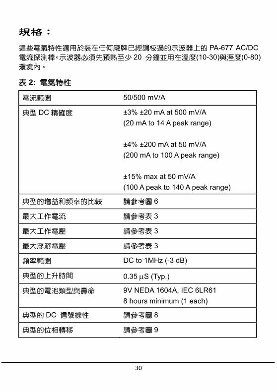
規格: 這些電氣特性適用於裝在任何廠牌已經調校過的示波器上的 PA-677 AC/DC 電流探測棒。示波器必須先預熱至少 20 分鐘並用在溫度(10-30)與溼度(0-80)環境內。
表 2: 電氣特性
電流範圍 50/500 mV/A
典型 DC 精確度
±3% ±20 mA at 500 mV/A
(20 mA to 14 A peak range)
±4% ±200 mA at 50 mV/A
(200 mA to 100 A peak range)
±15% max at 50 mV/A
(100 A peak to 140 A peak range)
典型的增益和頻率的比較 請參考圖 6
最大工作電流 請參考表 3
最大工作電壓 請參考表 3
最大浮游電壓 請參考表 3
頻率範圍 DC to 1MHz (-3 dB)
典型的上升時間 0.35 S (Typ.)
典型的電池類型與壽命 9V NEDA 1604A, IEC 6LR61
8 hours minimum (1 each)
典型的 DC 信號線性 請參考圖 8
典型的位相轉移 請參考圖 9

31
表 3: 電壓及電流測定
Rating 測定
Maximum working current (A) 最大工作電流 (A)
Maximum Working voltage (V) 最大工作電
壓
Maximum floating voltage (V) 最大浮游電
壓
Range (範圍)
50 mV/A
Range(範圍)
500 mV/A
DC 70* 7 600 600
DC + peak AC
70* 7 600 600
AC peak 70 7 600 600
AC peak – peak
140 14 1200 -
RMS CAT III 50 5 600 600
RMS CAT II 50 5 600 600
RMS CAT I 50 5 600 600
*請參考圖7頻率降低額定值
表 4: 物質的特性
尺寸 262 mm x 81 mm x 36 mm (10.3 x 3.2 x 1.4 inch)
測量導體最大尺寸 10.3 mm (0.4 inch)
導線長度 100 cm( 3.3 feet)
重量 310 g (11 oz) (不含電池重量)

32
表 5: 環境的特性
工作時溫度
貯藏時溫度
攝氏 0°C 到 + 50°C
(華氏+32°F 到 + 122°F)
攝氏 -20°C 到 + 80°C
(華氏-4°F 到 176°F)
濕度 攝氏 0°C 到 40°C, 濕度 95%
攝氏 40°C to 50°C, 濕度 45%
汙染程度 2
圖 6: 典型的增益對頻率在 1A 峰值時對應圖

33
圖 7: 最高電流量對頻率
圖 8: 典型的 DC 信號線性在 50 mV/A 範圍時

34
圖 9: 典型的位相對頻率在 1A 峰值時
表 6: 認證與條件符合
EC 符合性聲明-
低電壓
法規遵從性被證實在以下的規格如同登記在歐洲
聯盟的官方刊物裡:
低電壓指令 73/23/EEC,如 93/68/EEC 所修正
的
EN 61010-1/A2:1995 電器設備的安全要求用於測量,控制和實驗室
EN 61010-2-032:1995 手握電流夾的特定規定用於電器測量及實驗設
備。
其他遵從的法規 IEC61010-1/A2:1995 電器設備的安全要求用於測量,控制和實驗室
IEC61010-2-032:1994 手握電流夾的特定規定用於電器測量及實驗設
備。

35
表 6: 認證與條件符合(續上頁)
Installation (Overvoltage) Category
安裝類別 (過電壓)
本產品可能有不同的安裝(過電壓)類別名稱。安裝類別有:
CATIII
分佈級扼要(通常永久連接著)。在此級
別的設備,通常是在固定的產業位置。
CATII
地方級扼要 (牆上的插座)。在此級別
的設備包括電器,可攜式工具及同類
產品。設備通常以電纜線連接。
CAT I
次要的(信號級別)或電池供電之電子
設備電路。
Pollution Degree
汙染程度
測量周邊產品環境中和產品裡可產生
的污染。產品的內部環境通常被視為
跟外部環境是同樣的。產品應該只使
用在它們所評定的環境中。
汙染指數 1
無汙染或只有乾的,不導電的污染產
生。在這分類裡的產品一般為封裝
的,密封的或位於潔淨室。
汙染指數 2
通常只有乾的,不導電的污染產生。
有時必須預期會有因凝結所造成的臨
時導電。這通常是位於辦公室/家庭環
境的。臨時導電只會在沒有保養時發
生。

36
可更換的零件: 1. PA-677 AC/DC 電流探測棒是跟以下的物品一起運送的:
一本使用手冊:
英文與中文共用版。
一條 BNC TO BNC 同軸電纜線:
本公司型號為 BP-250,長度為 100 公分。
一個 AC 電源轉接器:
購買時請先選定以下型號,各國之間的插座形狀與電壓系統相異:
ADP-100V-JS 日本國專用。
ADP-110V-UL 美國或美規電源國適用。
ADP-220V-VDE 德國或歐規電源國適用。
ADP-230V-AS 澳洲或紐西蘭專用。
ADP-240V-BS 英國或適用英規插座區。
2. 跟數字型電錶一起使用之推薦的配件:
一個 BNC 轉香蕉插頭轉接器:
本公司型號為 MT-246N 有顏色防呆設計,避免連接數字型電錶時極性發生
錯誤。
PA-677 沒有任何用戶可修的裝配,如你的測試鉗有問題,請洽當地的服務
中心或代理商。

37
Accessories / 附件:
ADP-110 or 220 ...
MT-246N
BP-250PA-677
The diagram showing how PA-677 connect to Oscilloscope or DMM. PA-677 連接到示波器或數位電錶示意圖。

38

39
TINSE0084S4 Ver.02
Made In Taiwan