7 Easy Steps to Implementing Application Load Balancing ...
20
Visit coyotepoint.com for more information. The recognized leader in proven and affordable load balancing and application delivery solutions 7 Easy Steps to Implementing Application Load Balancing For 100% Availability and Accelerated Application Performance By Ralph Cardone Coyote Point Systems, Inc. White Paper
Transcript of 7 Easy Steps to Implementing Application Load Balancing ...

Visit coyotepoint.com for more information.
The recognized leader in proven and affordable
load balancing and application delivery solutions
7 Easy Steps to Implementing Application Load Balancing For 100%
Availability and Accelerated Application Performance
By Ralph Cardone Coyote Point Systems, Inc.
White Paper

Copyright © 2012 Coyote Point Systems. All rights reserved.
Coyote PointTM, EqualizerTM, Equalizer OnDemandTM, Equalizer VLBTM, EnvoyTM, E205GXTM, E350GXTM, E450GXTM, E650GXTM and Smart ControlTM are trademarks of Coyote Point Systems, Inc. in the U.S. and other countries.
MicrosoftTM, WindowsTM and SharePointTM are trademarks of Microsoft Corporation.
All other brand or product names referenced in this document are the respective trademarks of their respective owners.
The specifications and information contained in this document are subject to change without notice. All statements, information and recommendations are believed to be accurate but are presented without warranty of any kind, express or implied. Users must take full responsibly for their application thereof.
Document Name: WP_7StepstoLoadBalancing_V1_020212
Document version: 1.0
February, 2012
Table of Contents Introduction.................................................................................................................................................. 1
Fitting a Coyote Point Load Balancer into Your Network ................................................................... 2
The Seven Steps ........................................................................................................................................... 4
Step 1: Preparation .................................................................................................................................. 4
Step 2: Adding the Equalizer to the Network ....................................................................................... 5
Step 3: Adding Servers to Equalizer ...................................................................................................... 6
Step 4: Configure a Server Pool ............................................................................................................. 7
Adding Server Instances to the Server Pool ..................................................................................... 9
Step 5: Configure a Virtual Cluster ...................................................................................................... 10
Step 6: Configure Default Gateways on the Web Servers ................................................................ 12
Viewing the Cluster Setup ................................................................................................................. 13
Step 7: DNS Cut-over ............................................................................................................................. 15
Drop In Simplicity – Added Capabilities .................................................................................................. 15
Equalizer Options ...................................................................................................................................... 15
Contact Us! ................................................................................................................................................. 16

This Page has been intentionally left blank.
1 | White Paper: 7 Easy Steps to Implementing Application Load Balancing
Introduction The idea of load balancing is well defined in the IT world. Its primary function is to distribute a workload across multiple computers or a computer cluster, network links, CPUs or other resources. The result achieved is maximized application availability, optimized resource utilization, maximized throughput, minimized response times, and of course, avoiding application server overload. A load balancing appliance accepts traffic on behalf of a group (cluster) of servers and distributes that traffic according to load balancing algorithms and the availability servers and applications delivering services. From network administrators to server administrators and application developers, this is a generally well-understood concept.
Implementing load balancing, however, may be less understood. There are a plethora of questions including how an Application Delivery Controller (ADC) should be deployed for load balancing, how the servers should be configured, and if the overall network architecture needs to change to accommodate load balancing appliances. Organizations may cringe at the perceived scope and potential cost of implementing this methodology and this type of appliance into their infrastructure.
The good news is that deploying an ADC for load balancing needn’t be perplexing or difficult at all. In fact, installing a Coyote Point Equalizer™ ADC into your existing web server infrastructure can be accomplished easily and with minimal changes to your existing network configuration. To better illustrate this point, this document demonstrates how a common web server installation can be outfitted with an Equalizer ADC to provide load balancing with virtually no changes to your network architecture using a simple “drop-in” deployment strategy. And best of all, you don’t need to be an Equalizer expert or networking guru to successfully install the Equalizer ADC.
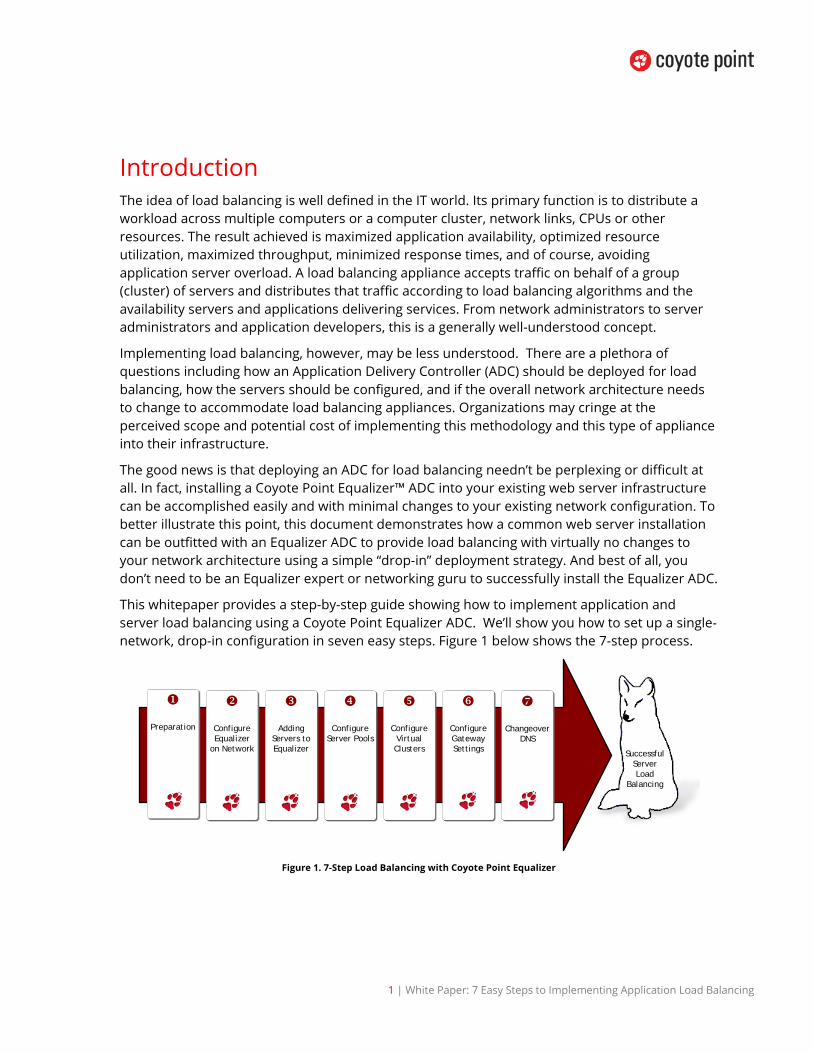
This whitepaper provides a step-by-step guide showing how to implement application and server load balancing using a Coyote Point Equalizer ADC. We’ll show you how to set up a single-network, drop-in configuration in seven easy steps. Figure 1 below shows the 7-step process.
Preparation
Configure Equalizer
on Network
Adding Servers to Equalizer
Configure Server Pools
Configure Virtual Clusters
Configure Gateway Settings
Changeover DNS
Successful Server Load
Balancing
Figure 1. 7-Step Load Balancing with Coyote Point Equalizer

2 | White Paper: 7 Easy Steps to Implementing Application Load Balancing
If you understand networking from a server perspective, then you’ve got the knowledge necessary to drop a Coyote Point Equalizer ADC into a network and configure a fully load balanced environment. The following section explains how Equalizer can easily fit into your existing network.
Fitting a Coyote Point Load Balancer into Your Network
The Coyote Point Equalizer series of ADC appliances are flexible come in a variety if performance options and can be implemented to provide 100% availability and higher application performance in a wide variety of network configurations. To demonstrate how Equalizer ADCs can be easily assimilated into your network, this document presents a single-network description. This configuration has several advantages that make Equalizer particularly simple to implement including:
• There is no need for additional subnets or physical networks • The servers do not need to have their IP addresses changed • There is only one small change needed on the servers to fully implement load balancing • It works without changing existing network infrastructure • It cuts over seamlessly and does not interrupt site traffic even if connections go back to
the old IP address.
Equalizer ADCs are often implemented into the most complex networks and application routing environments. We have chosen a simple “drop-in” case to highlight how easily an ADC be added into an existing infrastructure. If we take as an example a very common web server installation we can easily illustrated it. In Figure 2 we show this very common configuration: The domain name points in DNS to the web server with the IP address 64.13.140.10. The firewall, located at 64.13.140.1, acts as the default gateway for the single web server.
Figure 2. Simple Web Server Network Configuration
If your business or customers depend on this web site, this configuration trades off simplicity for high vulnerability and possible service outages. There is no redundancy in case the web server or application were to suffer a failure, and expanding the capacity would require either

3 | White Paper: 7 Easy Steps to Implementing Application Load Balancing
upgrading memory/processors for the system, or replacing it entirely with a more powerful system.
Load balancing with an ADC is the single most effective way to scale an application. With a drop-in load balancing configuration, a single or redundant pair of Equalizer ADCs sits on a single network, on one subnet - the same network and subnet where the web servers currently reside. You don’t need to add additional networks, change the IP addresses of your servers, or add any extra networking gear. The application users are absolutely unaffected as the servers will still be accessible the exact same way they were before an ADC for load balancing was implemented.
Pictured in Figure 3 below are two Equalizer ADCs added to a web server network providing a redundant, load balancing configuration. In this example we add two more web servers, bringing the number of web servers to three. This dramatically increases the performance and availability of the web services applications.
Figure 3. Load Balancing Equalizers "Dropped Into" Web Server Network Configuration
While the servers can still be individually accessed, all web traffic will be directed to a separate IP address in the ADC, called a “Cluster”. The ADC will accept traffic for the Cluster and distribute it to the available servers in the server pool assigned to the cluster. In the case of a redundant load balancing configuration as is shown above, if the active Equalizer ADC were to go off-line the Cluster’s Virtual IP address would automatically switch to the Equalizer ADC in hot standby.
Beyond load balancing, Equalizer ADCs have additional capabilities that ensure the highest application availability. By performing health checks on the three servers, as well as the applications running on the servers, Equalizer ensures that they are capable of either serving content or delivering the application(s) to clients. If one web server goes down, or the server stays active but the application crashes, Equalizer stops sending traffic to that server and routes traffic to the remaining active servers. Messages can be sent to IT staff notifying them of the outage. Once the server/application comes back up, Equalizer automatically recognizes it and resumes sending traffic to it.
4 | White Paper: 7 Easy Steps to Implementing Application Load Balancing
Each Equalizer has an individual IP address on each VLAN, which is used for management. In addition, both Equalizers share a “failover” address sometimes called a “floating” IP address. Like the Cluster address, the floating address exists only on an active Equalizer. This floating IP also serves as the default gateway for the web servers behind Equalizer.
While the servers change their default gateway to the floating IP address, both Equalizers have their default gateway set to a firewall or another layer 3 device such as a router; the effect is that the outbound gateway for the entire configuration is still the firewall. The web servers have inbound and outbound Internet access just as they did before Equalizer was installed, and are limited only by the firewall’s security profile. In this example Equalizer is the default gateway and traffic passes through Equalizer in both inbound and outbound directions.
NOTE: When performing a test or proof-of-concept deployment it is possible to not set the servers default gateway to the Equalizer by leveraging the Spoof option on the clusters. This is explained in further detail in the EQ/OS 10 Administration Guide.
Inbound traffic will be changed to use the Cluster IP Address instead of the server address previously used (64.13.140.10). This change will be made in DNS once installation is complete, eliminating any interruption of service.
As simple as that was, the hardest part is already behind us. Let’s now proceed with seven easy steps to load balancing.
The Seven Steps The seven steps for implementing Application Load Balancing using a Coyote Point Equalizer are:
1. Preparation - there are a few minor preparatory steps that you’ll want to take before implementation.
2. Configuration of Equalizer on the Network - the simple process of adding an Equalizer on the network.
3. Adding Servers to Equalizer - the process of entering the IP addresses and ports for the real web servers behind Equalizer.
4. Configure Server Pools -setting load balancing parameters that will apply to a group of real web servers.
5. Configure Virtual Clusters - configuring the Equalizer Virtual Clusters. The clusters accept connections on behalf of the web servers.
6. Configure Server Gateways - changing the configuration on the web servers to the default gateway.
7. Changeover DNS - switching the DNS for your site from the old IP (directly accessing the first web server) to the IP address of the new Virtual Cluster on Equalizer.
Step 1: Preparation
There are a few minor preparatory steps that you’ll want to take before implementation to ensure a successful deployment. First, you’ll need two additional IP addresses on your network

5 | White Paper: 7 Easy Steps to Implementing Application Load Balancing
if you’re running a single Equalizer in stand-alone mode or four additional IP addresses if you’re running redundant Equalizers in high availability mode.
You’ll also want to change the TTL (Time To Live) on your domain name (or names) to zero or the lowest value you can set so that clients are directed to the new IP address as soon as the change is made to the DNS. This will make the cut-over from the single web server to the load balancer quicker. Your DNS provider (whoever shows up in a WHOIS for the domain), typically your ISP should be able to accommodate this request.
Step 2: Adding the Equalizer to the Network
Adding an Equalizer to a single network configuration is very simple and begins with the physical connection. You’ll use Equalizer’s Default VLAN Interface ports. Equalizer’s default VLAN ports are Port 1 and 2 as shown in Figure 4 below. Additional ports can be added through the Administrative Interface if required. At least one port from each Equalizer must be plugged into the same switch or hub infrastructure that the firewall (or upstream router) is plugged into.
Figure 4. Port Layout of an Equalizer
The servers can either be plugged directly into the available Equalizer network ports, or they can plug into the same switch or hub infrastructure that each Equalizer plugs into.
Power-up each Equalizer and set up the Default VLAN using “eqcli”, the command line interface as described in the EQ/OS 10 Administration Guide. Virtual Local Area Network (VLAN) technology was developed to overcome the physical limitations of traditional LAN technology and is essentially a means of grouping systems using methods that are independent of the physical connection of the device to the network. Assign IP addresses and hostnames to each Equalizer. The IP addresses for Equalizer 1 and Equalizer 2 are assigned to the Default VLAN on the Equalizers using the command line interface through Equalizer’s serial port using a terminal emulator. Initial configuration is done using the included serial cable and a serial terminal; or, a terminal emulator application. Windows® HyperTerminal, which is included with most versions of Microsoft® Windows®, can also be used.
6 | White Paper: 7 Easy Steps to Implementing Application Load Balancing
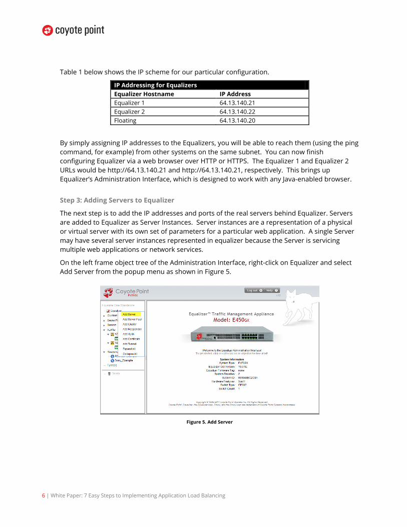
Table 1 below shows the IP scheme for our particular configuration.
IP Addressing for Equalizers Equalizer Hostname IP Address Equalizer 1 64.13.140.21 Equalizer 2 64.13.140.22 Floating 64.13.140.20
By simply assigning IP addresses to the Equalizers, you will be able to reach them (using the ping command, for example) from other systems on the same subnet. You can now finish configuring Equalizer via a web browser over HTTP or HTTPS. The Equalizer 1 and Equalizer 2 URLs would be http://64.13.140.21 and http://64.13.140.21, respectively. This brings up Equalizer’s Administration Interface, which is designed to work with any Java-enabled browser.
Step 3: Adding Servers to Equalizer
The next step is to add the IP addresses and ports of the real servers behind Equalizer. Servers are added to Equalizer as Server Instances. Server instances are a representation of a physical or virtual server with its own set of parameters for a particular web application. A single Server may have several server instances represented in equalizer because the Server is servicing multiple web applications or network services.
On the left frame object tree of the Administration Interface, right-click on Equalizer and select Add Server from the popup menu as shown in Figure 5.
Figure 5. Add Server
7 | White Paper: 7 Easy Steps to Implementing Application Load Balancing
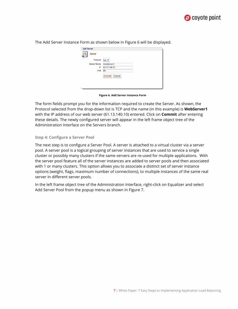
The Add Server Instance Form as shown below in Figure 6 will be displayed.
Figure 6. Add Server Instance Form
The form fields prompt you for the information required to create the Server. As shown, the Protocol selected from the drop-down list is TCP and the name (in this example) is WebServer1 with the IP address of our web server (61.13.140.10) entered. Click on Commit after entering these details. The newly configured server will appear in the left frame object tree of the Administration Interface on the Servers branch.
Step 4: Configure a Server Pool
The next step is to configure a Server Pool. A server is attached to a virtual cluster via a server pool. A server pool is a logical grouping of server instances that are used to service a single cluster or possibly many clusters if the same servers are re-used for multiple applications. With the server pool feature all of the server instances are added to server pools and then associated with 1 or many clusters. This option allows you to associate a distinct set of server instance options (weight, flags, maximum number of connections), to multiple instances of the same real server in different server pools.
In the left frame object tree of the Administration Interface, right-click on Equalizer and select Add Server Pool from the popup menu as shown in Figure 7.
8 | White Paper: 7 Easy Steps to Implementing Application Load Balancing
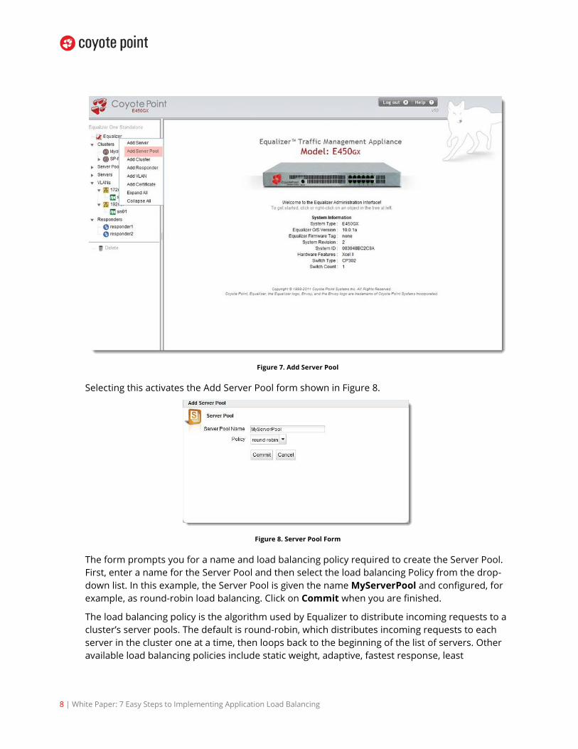
Figure 7. Add Server Pool
Selecting this activates the Add Server Pool form shown in Figure 8.
Figure 8. Server Pool Form
The form prompts you for a name and load balancing policy required to create the Server Pool. First, enter a name for the Server Pool and then select the load balancing Policy from the drop-down list. In this example, the Server Pool is given the name MyServerPool and configured, for example, as round-robin load balancing. Click on Commit when you are finished.
The load balancing policy is the algorithm used by Equalizer to distribute incoming requests to a cluster’s server pools. The default is round-robin, which distributes incoming requests to each server in the cluster one at a time, then loops back to the beginning of the list of servers. Other available load balancing policies include static weight, adaptive, fastest response, least

9 | White Paper: 7 Easy Steps to Implementing Application Load Balancing
connections, server agent and custom. If you select the custom policy option sliders appear that you can set to configure the custom load balancing behavior you desire in the Configuration > LB Policy tab shown in Figure 9 which is displayed after clicking Commit and creating the Server Pool.
Figure 9. Server Pool Configuration
Next, we’ll group our servers within our new Server Pool.
Adding Server Instances to the Server Pool Now that the Server Pool is configured, it’s time to add instances of the web servers to them. Right-click on the name of the new Server Pool in the left frame object tree and select Add Server from the popup menu. An Add Server Instance Form as shown in Figure 10 is displayed that prompts you for the settings required to create the new Server Pool.
Figure 10. Add Server Instance
In Figure 10 above you can see that WebServer_1 is selected. WebServer_1 has the IP address of our web server. An Initial Weight slider is set to 100 (default). Equalizer uses the initial weight setting as the starting point for determining what percentage of requests to route to the

10 | White Paper: 7 Easy Steps to Implementing Application Load Balancing
selected server pool. Click Commit to create Server Instance in the Server Pool. Once it is created, Equalizer opens the Server Pool’s Configuration tab shown in Figure 11.
Figure 11. Server Instance Configuration
We’ll leave the other server pool parameters set to their default values and discuss a couple of the more important ones briefly before we add additional server instances in the Server Pool.
As stated above, Equalizer uses a site’s initial weight as the starting point for determining what percentage of requests to route to that site. Equalizer assigns sites with a higher initial weight a corresponding higher percentage of the load. The relative values of site initial weights are more important than the actual values. For example, if two sites are in a Cluster and one has roughly twice the capacity of the other, setting the initial weights to 50 and 100 is equivalent to setting the initial weights to 100 and 200.
The Maximum Connections slider is used to configure Equalizer to allow a user to limit the size of the reusable connection pool -- which in turn limits the amount of memory and CPU resources used to manage HTTP multiplexing.
Now let’s add the Server Pools to Virtual Clusters.
Step 5: Configure a Virtual Cluster
The next step is to configure a Virtual Cluster. The Cluster is what accepts connections to be delivered to the appropriate servers. Eventually, a site’s DNS entry will point to the Virtual Cluster IP.
In the left frame object tree of the Administration Interface, right-click on Equalizer and select Add Cluster from the popup menu as shown in Figure 12.
11 | White Paper: 7 Easy Steps to Implementing Application Load Balancing
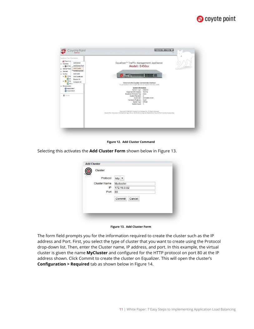
Figure 12. Add Cluster Command
Selecting this activates the Add Cluster Form shown below in Figure 13.
Figure 13. Add Cluster Form
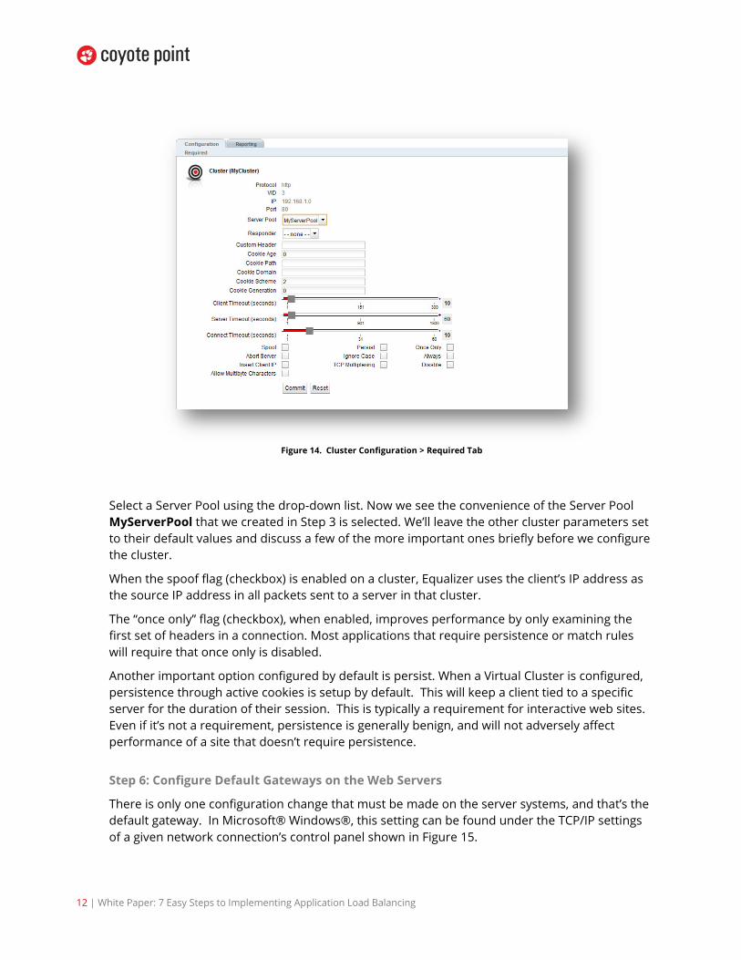
The form field prompts you for the information required to create the cluster such as the IP address and Port. First, you select the type of cluster that you want to create using the Protocol drop-down list. Then, enter the Cluster name, IP address, and port. In this example, the virtual cluster is given the name MyCluster and configured for the HTTP protocol on port 80 at the IP address shown. Click Commit to create the cluster on Equalizer. This will open the cluster’s Configuration > Required tab as shown below in Figure 14.
12 | White Paper: 7 Easy Steps to Implementing Application Load Balancing
Figure 14. Cluster Configuration > Required Tab
Select a Server Pool using the drop-down list. Now we see the convenience of the Server Pool MyServerPool that we created in Step 3 is selected. We’ll leave the other cluster parameters set to their default values and discuss a few of the more important ones briefly before we configure the cluster.
When the spoof flag (checkbox) is enabled on a cluster, Equalizer uses the client’s IP address as the source IP address in all packets sent to a server in that cluster.
The “once only” flag (checkbox), when enabled, improves performance by only examining the first set of headers in a connection. Most applications that require persistence or match rules will require that once only is disabled.
Another important option configured by default is persist. When a Virtual Cluster is configured, persistence through active cookies is setup by default. This will keep a client tied to a specific server for the duration of their session. This is typically a requirement for interactive web sites. Even if it’s not a requirement, persistence is generally benign, and will not adversely affect performance of a site that doesn’t require persistence.
Step 6: Configure Default Gateways on the Web Servers
There is only one configuration change that must be made on the server systems, and that’s the default gateway. In Microsoft® Windows®, this setting can be found under the TCP/IP settings of a given network connection’s control panel shown in Figure 15.

13 | White Paper: 7 Easy Steps to Implementing Application Load Balancing
Figure 15. Default Gateway Settings Shown on Windows 7” Internet Protocol Version 4 (TCP/IPv4) Properties”
The web servers use the Equalizer’s IP on the default VLAN if using a Stand-Alone configuration and the floating IP address if setup in Failover configuration.
When using a single network configuration where all of the servers and Equalizer are on the same subnet or when using the spoof option, the default gateway for all servers that are load balanced by Equalizer. This needs to be Equalizer’s floating gateway IP address. All of your other settings including the web server configuration can remain unchanged. Equalizer will work seamlessly with this configuration.
Viewing the Cluster Setup Now that your servers, server pools and clusters are configured, let’s return to the Equalizer Administration Interface. It’s a good idea to check out all of your cluster setups to see if they will load balance correctly. Click Clusters in the left frame and the Cluster Summary screen similar to the following is displayed on the right pane.

14 | White Paper: 7 Easy Steps to Implementing Application Load Balancing
Figure 16. Cluster Summary Screen
Use the “Filter By” radio buttons to change the display options. In Figure 16 Cluster Name is selected. You can also further customize your cluster details by using the checkboxes to determine which cluster on your Equalizer will be displayed.
There are several things of note in the Cluster Summary Screen. The first is the display of the Server Pools attached to each cluster. Note the icons:
The number to the left of the icon indicates the number of Server Pools that are working on the cluster.
The number to the left of the icon indicates the number of servers that are not responsive.
The number to the left of the icon indicates the number of issues that Equalizer cannot identify. These are normally active when probing is turned off.
Also note the number of connections with each cluster. The Responders associated with each cluster are used to send automated responses to clients when all the servers are down. If actual traffic is flowing through a cluster you would see values in the Cx (Connections) and TPS (Transactions per Second) columns.

15 | White Paper: 7 Easy Steps to Implementing Application Load Balancing
Step 7: DNS Cut-over
Ok, so now you’ve completed steps one through six. Your site should now ready to switch over with a DNS cut-over.
Contact your DNS provider (again, typically your ISP) and have them switch the DNS for your site from the old IP address (directly accessing the first web server) to the IP address of the Virtual Cluster on Equalizer. Also have them set the TTL for your DNS entry to 0.
Because DNS can (and will) be cached despite TTL, the effect will not be immediate for all clients. However, since both the old IP address and the Virtual Cluster are both serving up the website, this will not affect your overall site availability. Over a period of 24-48 hours, traffic will migrate to the Virtual Cluster without service interruption.
Drop In Simplicity – Added Capabilities This solution can scale to many more web servers, Virtual Clusters, and serve multiple websites while providing advanced traffic management features such as persistence, health checking, and failover.
In addition, Coyote Point offers a software application called Envoy™ which is a software upgrade that adds global load balancing capabilities to provide failover and load distribution across multiple geographical locations.
With Coyote Point’s Equalizer drop-in solution, load balancing needn’t be difficult to implement or disruptive to your existing infrastructure. With this easy to understand, easy to implement solution, there is no reason to fear adding the benefits of load balancing to your infrastructure today.
Additional Equalizer ADC Benefits Here’s a quick look at Equalizer ADC appliance capabilities that further improve Equalizer’s ability to deliver cutting edge application traffic management solutions:
Hardware SSL Acceleration – All Equalizers have the ability to offload SSL processing from the application servers. The Equalizer E450GX and E650GX ADC models contain the Xcel II™ SSL Accelerator Card, which dramatically improves Equalizer’s ability to process HTTPS transactions by offloading processor-intensive SSL operations to purpose-built Xcel™ on-card processor. Offloading SSL processing to the Xcel card frees Equalizer to apply all its own processing power to manage application traffic at high speed. Your servers are then free to use all their processing power to do what they do best: servicing application users.
Hardware Data Compression - Equalizer E650 models are configured with the Express™ GZIP Compression Card, which provides data compression for server responses. This reduces the size of the payloads Equalizer sends back to clients over the network. This does two positive things. First it helps businesses make the most of expensive resources like bandwidth and secondly the smaller compressed data packets speed up the application response times for the user. Since all
16 | White Paper: 7 Easy Steps to Implementing Application Load Balancing
compression is performed on the Express card, compression operations are fast and don’t interfere with normal Equalizer operation.
Envoy Geographic Server Load Balancing (GSLB) - Envoy is Equalizer’s GSLB solution, providing scalable application load balancing and acceleration amongst geographically distributed data centers. Envoy empowers you to take full advantage of distributed application infrastructures, mitigates the risk of data center outages, provides disaster recovery for application servers, reduces bandwidth costs, and accelerates end user response time by directing user requests to the ‘closest’ data center.
Contact Us! Bring us your application delivery challenges and let us demonstrate to you the benefits that Coyote Point’s affordable, non-stop, application acceleration and load balancing ADC technology can bring to your business. You can contact us conveniently from the web at http://www.coyotepoint.com/contact.php or by calling us at 1-877-367-2696.