7+( 352-(&7 )25 &$3$&,7< (1+$1&(0(17 ,1 52$' 0$,17 ... - JICA
226
JAPAN INTERNATIONAL COOPERATION AGENCY DIRECTORATE FOR ROADS OF VIETNAM MINISTRY OF TRANSPORT THE SOCIALIST REPUBLIC OF VIET NAM THE PROJECT FOR CAPACITY ENHANCEMENT IN ROAD MAINTENANCE PHASE-II Final Report VOLUME 3.3: EXPRESSWAY MAINTENANCE MANUAL March 2018 JAPAN INTERNATIONAL COOPERATION AGENCY (JICA) KATAHIRA & ENGINEERS INTERNATIONAL CENTRAL NIPPON EXPRESSWAY CO. LTD. ORIENTAL CONSULTANTS PASCO CORPORATION 18-027 JR EI
Transcript of 7+( 352-(&7 )25 &$3$&,7< (1+$1&(0(17 ,1 52$' 0$,17 ... - JICA

JAPAN INTERNATIONAL COOPERATION AGENCY DIRECTORATE FOR ROADS OF VIETNAM
MINISTRY OF TRANSPORT THE SOCIALIST REPUBLIC OF VIET NAM
THE PROJECT FOR
CAPACITY ENHANCEMENT IN ROAD MAINTENANCE PHASE-II
Final Report
VOLUME 3.3: EXPRESSWAY MAINTENANCE
MANUAL
March 2018
JAPAN INTERNATIONAL COOPERATION AGENCY (JICA)
KATAHIRA & ENGINEERS INTERNATIONAL CENTRAL NIPPON EXPRESSWAY CO. LTD.
ORIENTAL CONSULTANTS PASCO CORPORATION 18-027
JR
EI

Concept of Development
(1) Expressway Maintenance Manual is a reference material aiming to provide information on the
expressway maintenance procedures to the DRVN, RMBs and SBs staff currently involved in the
expressway maintenance and management activities in the field.
(2) The maintenance management procedures covered in this manual ranges from road facility
inspection, diagnosis, maintenance and repair work selection and the implementation of maintenance
and repair work to be carried out in conjunction with routine maintenance and periodic repair on the
expressway systems.
The Project for Capacity Enhancement in Road Maintenance in Vietnam Phase II
i Expressway Maintenance Manual
TABLE OF CONTENTS
1. SCOPE OF APPLICATION ......................................................................................................... 1
2. QUOTED DOCUMENTS ............................................................................................................ 1
3. TERMS AND DEFINITIONS ...................................................................................................... 2
Organization with legal ownership ............................................................................................... 3
Abbreviations: .............................................................................................................................. 3
4. GENERAL REGULATIONS ....................................................................................................... 3
5. PRINCIPLE OF ROAD FACILITY INSPECTION .................................................................. 4
Objective of Road Facility Inspection .......................................................................................... 4
Classification of Road Facility Inspection .................................................................................... 4
Procedures of Road Facility Inspection ........................................................................................ 5
Formulation of Road Facility Inspection Plans .................................................................... 5
Inspection Facilities .............................................................................................................. 6
Inspection Methods .............................................................................................................. 6 Inspection Devices ............................................................................................................... 6
Standard Inspection Frequency ............................................................................................ 7
Safety Measures during Inspection ...................................................................................... 7
Evaluation of Inspection Results .......................................................................................... 8 Implementation of Detailed Inspection ................................................................................ 8
Formulation of Monitoring Plans ......................................................................................... 9
Formulation of Maintenance and Repair Plans .................................................................... 9
Registration of Inspection Data and Reporting .................................................................. 10
6. ROAD MAINTENANCE AND REPAIR TECHNOLOGIES ................................................. 10
Road Slope Maintenance Management ...................................................................................... 10
Introduction ........................................................................................................................ 10
Road Slope Protection Technology .................................................................................... 11
Typical Damages Observed ................................................................................................ 11 Inspection of Road Slope.................................................................................................... 12
Planning and Implementation of Maintenance and Repair Work ....................................... 16
Planning and Implementation of Emergency Repair Work ................................................ 22
Drainage System Maintenance Management ............................................................................. 27
Introduction ........................................................................................................................ 27 Classification of Drainage Systems .................................................................................... 27
Typical Damages Observed ................................................................................................ 30
The Project for Capacity Enhancement in Road Maintenance in Vietnam Phase II
ii Expressway Maintenance Manual
Inspection of Drainage Systems ......................................................................................... 31
Planning and Implementation of Maintenance and Repair Work ....................................... 32
Road Pavement Maintenance Management................................................................................ 35
Introduction ........................................................................................................................ 35
Typical Damages Observed ................................................................................................ 35
Inspection of Road Pavement ............................................................................................. 40 Planning of Maintenance and Repair.................................................................................. 45
Implementation of Routine Maintenance ........................................................................... 50
Implementation of Periodic Repair..................................................................................... 57
Bridge Pavement maintenance Management .............................................................................. 64
Introduction ........................................................................................................................ 64 Typical Defects Observed ................................................................................................... 64
Inspection of Bridge Pavement .......................................................................................... 65
Planning of Maintenance and Repair Work ........................................................................ 66
Implementation of Maintenance and Repair ...................................................................... 66
Tunnel Pavement Maintenance and Management ...................................................................... 69
Bridge Maintenance Management .............................................................................................. 69
Introduction ........................................................................................................................ 69
Typical Damages Observed ................................................................................................ 69
Inspection of Bridge ........................................................................................................... 74 Planning and Implementation of Maintenance and Repair Work ....................................... 94
Data Registration of Maintenance and Repair History ..................................................... 128
Road Tunnel Maintenance Management .................................................................................. 128
Introduction ...................................................................................................................... 128
Typical Damages Observed .............................................................................................. 129 Inspection of Road Tunnel................................................................................................ 131
Planning and Implementation of Maintenance and Repair Work ..................................... 135
Culvert Box and Pipe Culver Maintenance Management ........................................................ 155
Introduction ...................................................................................................................... 155
Typical Damages Observed .............................................................................................. 155 Inspection of Culvert Box and Pipe Culvert ..................................................................... 155
Planning and Implementation of Maintenance and Repair ............................................... 157
Retaining Wall Maintenance Management ............................................................................... 157
Introduction ...................................................................................................................... 157 Classification of Retaining Walls ..................................................................................... 157
Typical Damages Observed .............................................................................................. 158
Inspection of Retaining Walls ........................................................................................... 158
Planning of Implementation of Maintenance and Repair Work for Revetment................ 162
The Project for Capacity Enhancement in Road Maintenance in Vietnam Phase II
iii Expressway Maintenance Manual
Traffic Safety Facility Maintenance Management ................................................................... 163
Introduction ...................................................................................................................... 163 Classification of Traffic Safety Facilities ......................................................................... 163
Typical Defects Observed ................................................................................................. 163
Inspection of Traffic Safety Facilities .............................................................................. 164
Planning and Implementation of Maintenance and Repair Work ..................................... 165
Traffic Management Facility Maintenance and Management .................................................. 167
Introduction ...................................................................................................................... 167
Classification of Traffic Management Facility ................................................................. 167
Typical Defects Observed ................................................................................................. 167 Inspection of Traffic Management Facilities .................................................................... 167
Planning and Implementation of Maintenance and Repair ............................................... 169
Road Cleaning .......................................................................................................................... 171
Introduction ...................................................................................................................... 171
Road Surface Cleaning ..................................................................................................... 172
Traffic Control .......................................................................................................................... 178
Objectives ......................................................................................................................... 178
Application of this Guideline ........................................................................................... 178
Law Observation .............................................................................................................. 178
Planning of Traffic Control .............................................................................................. 178 Particular Note of Traffic Control .................................................................................... 179
Classification of Traffic Control ....................................................................................... 179
Sample Intervention Levels of Bridge Inspection ........................................................................... 218
(Reference Material) ....................................................................................................................... 218

The Project for Capacity Enhancement in Road Maintenance in Vietnam Phase II
1 Expressway Maintenance Manual
1. SCOPE OF APPLICATION
(1) Expressway Maintenance Manual is a reference material aiming to provide information on the
expressway maintenance procedures to the DRVN, RMBs and SBs staff currently involved in the
expressway maintenance and management activities in the field.
(2) Expressway maintenance Manual covers procedures ranging from road facility inspection, diagnosis,
maintenance and repair work selection and the implementation of maintenance and repair work to
be carried out in conjunction with routine maintenance and periodic repair on the expressway
systems.
(3) The Manual shall not be applied to the investment projects such as rehabilitation and reconstruction
projects implemented aiming to upgrade road functions and capacities such as a widening project.
(4) The Manual shall not be applied to the expressways in operation under BOT or PFI scheme.
(5) The Manual shall not be applied to large-scale bridges, special bridges, ITS systems, toll systems,
vehicle weighing stations and road management facilities on the expressways.
2. QUOTED DOCUMENTS
The following documents are needed for the application of this Manual. For the reference documents
indicating year of publication, the version at the date shown below shall be used. For the reference
documents without year of publication, the latest edition shall be used, including revisions and
amendments (if any).
TCVN 7493/2005 Bitumen - Specifications
TCVN 7887/2008 National Technical Regulation on Road Signs and Signals
TCVN 8786/2011 Traffic Paints - Road marking materials: Water-borne paint -
Specifications and test methods
TCVN 8787/2011 Traffic Paints - Road Marking Materials: Solventborne Paint -
Specifications and Test Methods
TCVN 8788/2011 Traffic paints. Road marking materials: Solvent-borne and water-
borne paint - Procedures construction and acceptance TCVN
8860:2011 Hot Mix Asphalt Concrete Pavement – Specifications on
Construction and Acceptance
TCCS 02:2010/TCĐBVN Bridge Construction Specifications
TCVN 8867 - 2001 Flexible pavement - standard test method for determination of elastic
modulus of pavement structure using Benkelman girder
TCCS 07:2013/TCĐBVN Technical Specifications for Frequent Road Maintenance
TCCS 11-2013/TCĐBVN Specification for Road Management and Operation

The Project for Capacity Enhancement in Road Maintenance in Vietnam Phase II
2 Expressway Maintenance Manual
TCCS 12-2013/TCĐBVN Specification for Construction and Acceptance of Cement Concrete
Highway Pavement Structure
TCVN XXXX/2015 Design Standard on Strengthening RC Bridge Structure with Fiber –
reinforced plastic
TCVN XXXX/2015 Strengthening RC Bridge Structure with Fiber – reinforced plastic -
Specifications on Construction and Acceptance
3. TERMS AND DEFINITIONS
In this Manual, the following terms and definitions shall be used, which are defined in the regulations
stipulated in “2. Quoted Document”:
(1) Expressway means a road reserved exclusively for motor vehicles, with median strips separating
carriageways for the two opposite directions of traffic, without at-grade intersection with any road,
furnished with adequate support equipment and devices to ensure uninterrupted and safe traffic and
shorten travel time, and with certain points for vehicle exits and entries.
(2) Expressway Administration agency means the Directorate for Roads of Vietnam, the Ministry of
Transport; specialized agencies of People’s Committees of provinces and centrally run cities.
(3) Road Facility Inspection means checking of road facilities by visual or by inspection devices to
detect any damages on the facilities and to evaluate the damages for further survey or repair works.
(4) Work Maintenance means a collection of work to ensure and maintain proper and safe operation of
the work as indicated in the design during its lifespan, which includes routine maintenance, periodic
repair and emergency repair to keep road structures and properties as near as possible to their as-
constructed or renewed condition. Maintenance includes minor repairs and improvements to
eliminate the cause of defects and avoid excessive repetition of maintenance efforts.
(5) Routine Maintenance means the works to be implemented to prevent and promptly fix deficiency or
minor damages of road facilities and equipment components in order to enhance the operation
quality and prevent further damages and incidents and secure the service life of road facilities. These
operations are typically small scale or simple, but widely dispersed, and require skilled or un-skilled
manpower.
(6) Periodical repair is a scheduled remedial activity aiming to recover functions of facilities to initial
function and to improve the technical condition of road transport infrastructure assets, which cannot
be assured by routine maintenance. Moreover, it includes new replacement of old or aged equipment.
(7) Emergency repair means the works to be implemented when the components of rod facilities and
equipment are damaged by sudden effects from typhoons, floods, earthquakes, crashes, fires and
other unexpected affects or there are signs of sudden damages which affect the usage safety and
require prompt repair in order to ensure the smooth and safe traffic.

The Project for Capacity Enhancement in Road Maintenance in Vietnam Phase II
3 Expressway Maintenance Manual
Organization with legal ownership
(1) Definitions of functions, tasks, power and organization structure of the organization in charge of
expressway maintenance and management are stipulated in the relevant regulations.
(2) Units carrying out road facility inspection, road routine maintenance, periodic maintenance are those
who possess business license in construction and maintenance of transport works and who are
assigned and ordered or participated and bid accepted to implement road maintenance and
management.
(3) Road routine maintenance management according to executed method and quantity (MBC - Method
Based Contract) is the management type of traditional routine maintenance implementation based
on required methods and quantity and certified by Road Management Agency. The management type
may follow routine maintenance plan assigned by year or fixed rate of routine maintenance quantity
for unit carrying out road routine maintenance.
(4) Road routine maintenance management as per executed quality (PBC - Performance Based Contract)
is the management type of progressive routine maintenance implementation based on road quality
and works on the roads which are evaluated periodically according to united norms. This type of
management is carried out on the basis of road routine maintenance contracts through bidding, order
placing or assignment.
Abbreviations:
AC: Asphalt concrete
CC: Cement concrete
DRVN: Directorate for Roads of Vietnam
MBC: Method Based Contract
MOT: Ministry of Transport
PCI: Pavement Condition Index
PBC: Performance Based Contract
PDOT: Provincial Department of Transport
PSRC: Pre-stressed reinforced concrete
RC: Reinforced Concrete
ROW: Right of Way
RRMB: Regional Road Management Bureau
4. GENERAL REGULATIONS
Proper maintenance should be given to all expressways during their operation and lifespan. New
expressways should be maintained right after the work is put into use. Expressways under repair should
be maintained right after the repair work is done.
Expressway concessionaire should have an overall strategy on expressway maintenance, including
inspection, maintenance and repair (if necessary).

The Project for Capacity Enhancement in Road Maintenance in Vietnam Phase II
4 Expressway Maintenance Manual
5. PRINCIPLE OF ROAD FACILITY INSPECTION
This chapter stipulates principle of road facility inspection including procedures, methods and
technologies of inspection. Detail implementation guidance of road facility inspection shall be given in
each chapter of relevant road facility by facility type.
Objective of Road Facility Inspection
Road facility inspection is part road maintenance activities and has the following objectives;
- To quickly detect any incidents and abnormalities on the road facilities which may hinder road
and traffic functions.
- To provide information to the formulation of medium-term and long-term road asset
management plans which aims at optimizing maintenance and repair investment in the long
period of road maintenance.
Classification of Road Facility Inspection
(1) Road facility inspection for the national roads shall fall into the following five (5) categories; initial
inspection; routine inspection; periodic inspection, emergency inspection and detailed inspection.
(2) Initial inspection is to survey the initial status of road facilities that are taken over from construction
stage to maintenance stage.
(3) Routine inspection is a daily inspection done by traffic patrol staff to quickly find any unusual
incidents and defects which may provide negative effects on the road and traffic function of the
roadway, thereby maintain the service level of the road.
(4) Periodic inspection is to regularly survey defects and deterioration of road facilities, to evaluate them
in comparison with predetermined judgment criteria, to select the most suitable repair methods for
the damages and to preserve data in relevant databases. Periodic inspection provides base
information to the road asset management which aims to find out the most appropriate mid-
term/long-term investment for road maintenance and repair works.
(5) Emergency inspection is generally carried out in order to supplement the above inspections and to
cope with emergencies, such as unusual weather, traffic accidents and natural disasters.
(6) Detail inspection shall be implemented based on the decision made by evaluation committee to
further study the details of structural defects and deterioration of road facilities after periodic
inspection and to specify the causes of structural defects and deterioration. Also, it shall be
implemented to provide information for the designs of road repair works, including F/S, basic
designs and technical designs needed for repair works.
The Project for Capacity Enhancement in Road Maintenance in Vietnam Phase II
5 Expressway Maintenance Manual
Procedures of Road Facility Inspection
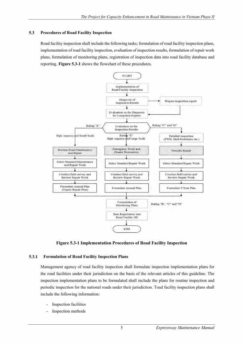
Road facility inspection shall include the following tasks; formulation of road facility inspection plans,
implementation of road facility inspection, evaluation of inspection results, formulation of repair work
plans, formulation of monitoring plans, registration of inspection data into road facility database and
reporting. Figure 5.3-1 shows the flowchart of these procedures.
Figure 5.3-1 Implementation Procedures of Road Facility Inspection
Formulation of Road Facility Inspection Plans
Management agency of road facility inspection shall formulate inspection implementation plans for
the road facilities under their jurisdiction on the basis of the relevant articles of this guideline. The
inspection implementation plans to be formulated shall include the plans for routine inspection and
periodic inspection for the national roads under their jurisdiction. Toad facility inspection plans shall
include the following information:
- Inspection facilities
- Inspection methods
The Project for Capacity Enhancement in Road Maintenance in Vietnam Phase II
6 Expressway Maintenance Manual
- Inspection devices
- Inspection frequencies
- Inspection schedule
- Inspection team organization
- Safety assurance during inspection
- Evaluation on the inspection results
- Formulation of repair work plans
- Recording of inspection results and reporting
For the implementation of initial road facility inspection on the new road facilities taken over to DRVN
for road maintenance and operation, DRVN shall designate a management agency of road facility
inspection in the region to implement inspection.
Inspection Facilities
Road facilities for inspection to be selected in this guideline shall include road pavements, slopes,
tunnels, box and pipe culverts, traffic safety and management facilities.
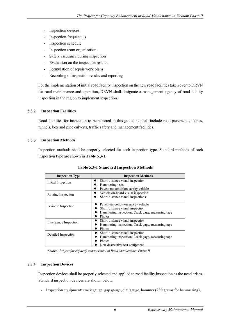
Inspection Methods
Inspection methods shall be properly selected for each inspection type. Standard methods of each
inspection type are shown in Table 5.3-1.
Table 5.3-1 Standard Inspection Methods
Inspection Type Inspection Methods
Initial Inspection Short-distance visual inspection Hammering tests Pavement condition survey vehicle
Routine Inspection Vehicle on-board visual inspection Short-distance visual inspections
Periodic Inspection Pavement condition survey vehicle Short-distance visual inspection Hammering inspection, Crack gage, measuring tape Photos
Emergency Inspection Short-distance visual inspection Hammering inspection, Crack gage, measuring tape Photos
Detailed Inspection Short-distance visual inspection Hammering inspection, Crack gage, measuring tape Photos Non-destructive test equipment
(Source) Project for capacity enhancement in Road Maintenance Phase-II
Inspection Devices
Inspection devices shall be properly selected and applied to road facility inspection as the need arises.
Standard inspection devices are shown below;
- Inspection equipment: crack gauge, gap gauge, dial gauge, hammer (230 grams for hammering),
The Project for Capacity Enhancement in Road Maintenance in Vietnam Phase II
7 Expressway Maintenance Manual
Schmidt hammer, binoculars, tape measure, metal tape, caliper square, tape, pole, wire-brush,
shovel, hand mirror, thermometer, etc.
- Inspection safety gears: goggles (for hammering), mobile phones (for communication), anti-dust
masks, safety belts, etc.
- Recording facilities: Digital camera, video recorder, black board, chalk, note pads, etc.;
- Other device: Traffic control facility (traffic cone, arrow signs, flags, etc.), stepladder, paint,
cohesive substances
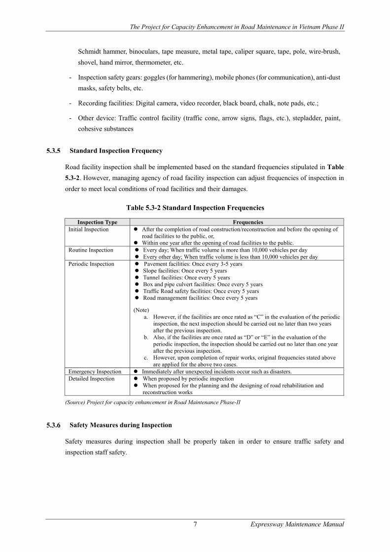
Standard Inspection Frequency
Road facility inspection shall be implemented based on the standard frequencies stipulated in Table
5.3-2. However, managing agency of road facility inspection can adjust frequencies of inspection in
order to meet local conditions of road facilities and their damages.
Table 5.3-2 Standard Inspection Frequencies
Inspection Type Frequencies Initial Inspection After the completion of road construction/reconstruction and before the opening of
road facilities to the public, or, Within one year after the opening of road facilities to the public.
Routine Inspection Every day; When traffic volume is more than 10,000 vehicles per day Every other day; When traffic volume is less than 10,000 vehicles per day
Periodic Inspection Pavement facilities: Once every 3-5 years Slope facilities: Once every 5 years Tunnel facilities: Once every 5 years Box and pipe culvert facilities: Once every 5 years Traffic Road safety facilities: Once every 5 years Road management facilities: Once every 5 years
(Note) a. However, if the facilities are once rated as “C” in the evaluation of the periodic
inspection, the next inspection should be carried out no later than two years after the previous inspection.
b. Also, if the facilities are once rated as “D” or “E” in the evaluation of the periodic inspection, the inspection should be carried out no later than one year after the previous inspection.
c. However, upon completion of repair works, original frequencies stated above are applied for the above two cases.
Emergency Inspection Immediately after unexpected incidents occur such as disasters. Detailed Inspection When proposed by periodic inspection
When proposed for the planning and the designing of road rehabilitation and reconstruction works
(Source) Project for capacity enhancement in Road Maintenance Phase-II
Safety Measures during Inspection
Safety measures during inspection shall be properly taken in order to ensure traffic safety and
inspection staff safety.

The Project for Capacity Enhancement in Road Maintenance in Vietnam Phase II
8 Expressway Maintenance Manual
Evaluation of Inspection Results
Evaluation of inspection results shall be conducted, applying criteria of 5 rating levels consisting of
A/B/C/D/E as shown in Table 5.3-3. The criteria are based on the following concepts; effects on
vehicle traffic and road environment; and the need of further survey.
- Rating “A” is applied when no damage or minor damages are observed, so that no repair work
is needed at this stage.
- Rating “B” is applied to the medium structural damages whose rapid progress is not expected
within 5 years. Repair work will be needed, but not urgent, so that monitoring is a major activity.
- Rating “C” is applied to medium and heavy structural damages expected to progress within 5
years. Repair works need to be planned within 5 years, so that detailed inspection is necessary
to find out the causes of the damages and the detail planning of repair works.
- Rating “D” is applied to heavy structural damages which need urgent repair work, so that
detailed inspection is needed to plan and design repair works in detail.
- Rating “E” is applied to the damages expected to give large negative effects on road traffic and
road environment. Urgent repair work is needed regardless of damage decree.
Table 5.3-3 Evaluation Criteria
Rating
Evaluation Criteria Effects on road
structural function
Effects on traffic and
environment
Need of further study
Measures to be taken
A No damage or minor structural damages
Small ----- ----- No repair work
B
Medium structural damages Progress of damages is not
expected within coming 5 years.
Repair works will be needed, but not urgent.
Medium ----- ----- Monitoring
C
Medium to Heavy structural damages
Progress of damages is expected within coming 5 years.
Repair works will be needed within 5 years.
Medium-large ----- Detailed inspection
Periodic repair (Planned works)
Monitoring
D Heavy structural damages Urgent repair work is needed.
Large ----- Detailed inspection
Periodic repair
Urgent repair Monitoring
E Large effects on road environment are expected.
----- Large ----- Routine
maintenance and repair
Implementation of Detailed Inspection
When the evaluation meeting makes a decision that further detailed inspection is needed (a rating level
of “C” or “D”), managing agency of road facility inspection shall take immediate actions to conduct
detailed inspection for the damages. Detailed inspection shall be implemented aiming to identify the
causes of damages, to find out the most appropriate repair works and to design repair works.

The Project for Capacity Enhancement in Road Maintenance in Vietnam Phase II
9 Expressway Maintenance Manual
Formulation of Monitoring Plans
Road facility inspection is in principle conducted based on the standard frequencies specified in this
relevant article of this Guideline. However, if a road facility inspection was conducted and the
evaluation was made on some of road facilities with “B”, “C”, “D” and “E” rating, the inspection
frequencies until next inspections need to be adjusted in particular for “C” and “D” rating. Managing
agency of road facility inspection shall formulate monitoring plans in order to keep watching the
progress of damages on the road facilities.
Formulation of Maintenance and Repair Plans
Managing agencies of road facility inspection shall formulate road routine maintenance plans, periodic
repair plans and emergency repair plans in accordance with Circular No.52/2013/TT-BGTVT.
Selection of Maintenance and Repair Works
Managing agencies of road facility inspection shall select maintenance and repair works for the
damages rated as “C”, “D” and “E”. Selection of repair works except those shown in this guideline
shall be based on the current practices implemented in the RMB regions. However, in case PMS is
applied to the formulation of periodic repair plans for “C” and “D”, repair works shall be automatically
selected in the computation processes of PMS model.
The selection of maintenance and repair plans shall be implemented for the small repair in the routine
maintenance and for the periodic repair, following the flowchart shown in Figure 5.3-1. Users are
required to select standard repair plans first for the above both cases, then to conduct detailed surveys
to identify local conditions and to review standard repair plans, taking account of local conditions.
Formulation of Maintenance Repair Plans
Road routine maintenance plans, which are annual plans, shall include regular routine maintenance
works and urgent repair works for the damages rated as “E” during road facility inspection, which are
expected to provide large effects to vehicle traffic and road environment. Temporary restoration works
for the damages given by disasters shall be included in the routine maintenance and repair plans. Full-
scale restoration works shall be registered into emergency repair works stated below.
Periodic repair plans shall include repair plans aiming to repair medium or heavy damages rated as
“C” or “D” during road facility inspection. Periodic repair plans shall be classified into annual plans
and 3-year plans, depending upon the urgency of repair works. If periodic repair works need urgent
implementation, periodic repair plans shall be registered into annual plans. On the other hand, if
periodic repair works do not need urgent implementation, periodic repair works shall be registered
into 3-year planned repair plans.
Emergency repair plans shall include repair plans for the damages given by disasters which are rated
as “D” during road facility inspection.

The Project for Capacity Enhancement in Road Maintenance in Vietnam Phase II
10 Expressway Maintenance Manual
Estimation of Maintenance and Repair Work Volumes
Work volumes for maintenance and repair works shall be estimated for each of the work. Repair work
volume estimation for periodic and emergency works shall be based on the results of detailed
inspection, design materials conducted in0 the detailed inspection and field observation. However, in
case PMS is applied in the formulation of periodic repair plans for “C” and “D” rating, estimation of
work volumes for periodic repair works shall be automatically made in the computation processes of
PMS model.
Registration of Inspection Data and Reporting
Inspection results shall be recorded in the data registration forms shown in Table 5.3-4. Inspection
supervision agency (SB) shall report inspection results to inspection management agency (RMB) and
DRVN regularly.
Table 5.3-4 Data Input Form
Inspection type Data Registration Form
Pavement inspection (by Road Condition Survey) ANNEX-I_P1 ANNEX-J
Pavement inspection (by Visual Inspection) ANNEX-I_P2 ANNEX-J
Slope inspection ANNEX-I_S-1 ANNEX-J
Tunnel inspection ANNEX-I_T-1 ANNEX-J
Box and pipe culver inspection ANNEX-I_C-1 ANNEX-J
Traffic safety facility inspection ANNEX-I_TS-1 ANNEX-J
Traffic management facility inspection ANNEX-I_TM-1 ANNEX-J
6. ROAD MAINTENANCE AND REPAIR TECHNOLOGIES
Road Slope Maintenance Management
Introduction
The Guideline regulates the focus points of road slope maintenance including damage types of road
slopes, inspection and diagnosis of slope damages, and maintenance work selection against road slope
damages. Road slopes in general fall into the following two types; (1) a natural slope and (2) a
structurally protected slope. Cut slopes
It is known that cut slopes including natural slopes and artificially protected slopes shall be weathered
and deteriorated and eventually becomes weakened as time passes after construction. Road slope
damages shall often provide serious damages to road and traffic functions, often giving a large negative
effect to regional socio-economy. A key point of road slope maintenance is to detect any abnormalities
arising on the road slopes and to take immediate actions against these changes before leading to serious
damages and providing serious effects on traffic safety and regional socio-economy.
The Project for Capacity Enhancement in Road Maintenance in Vietnam Phase II
11 Expressway Maintenance Manual
Road Slope Protection Technology
Natural Slopes with Seeding, Sodding and Planting
Planting including seeding and sodding becomes effective only when plants grow successively for a
long term to come and when they are taken care of appropriately. The method of planting falls into
two categories: seeding and sodding. Table 6.1-1 shows the objectives of these technologies.
Table 6.1-1 Planting Technologies and Purposes
Maintenance and Repair Technology Objectives Seeds spraying; Sodding mat; Sodding To prevent rain water causing soil erosion, greening, vegetation around
the area Seed matting; Strip sodding To prevent rain water causing soil erosion, greening, vegetation around
the area, vegetation rows on the mound for embankment Seed board; Seed packet; Pick-hole seeding
To prevent rain water causing soil erosion, greening, vegetation around the area and partial vegetation on borrow soil in the cut slope.
Structurally Protected Slopes
For areas which are not suitable for planting, the areas where planted by tree still not making sure of
the stability of slopes, or areas at risk of fracture, erosion, collapse; they should be applied to the
method reinforced with structural materials. Table 6.1-2 shows basic method of reinforcement
Table 6.1-2 Slope Protection Technologies and Purposes
Protection Technologies Purposes Mortar spraying Concrete spraying Stone pitching Concrete block pitching Concrete block crib
Against weathering, erosion
Concrete pitching Cast-in-place concrete crib Slope anchor
Against weathering, erosion Preventing sloping surface cracks, anti-fracture, the rock avalanche,
Net hurdling Slope gabion
Preventing landslides in tilt surface layer
Rock fall prevention net Rock fall prevention fence Rock fall shed
Preventing rock slides
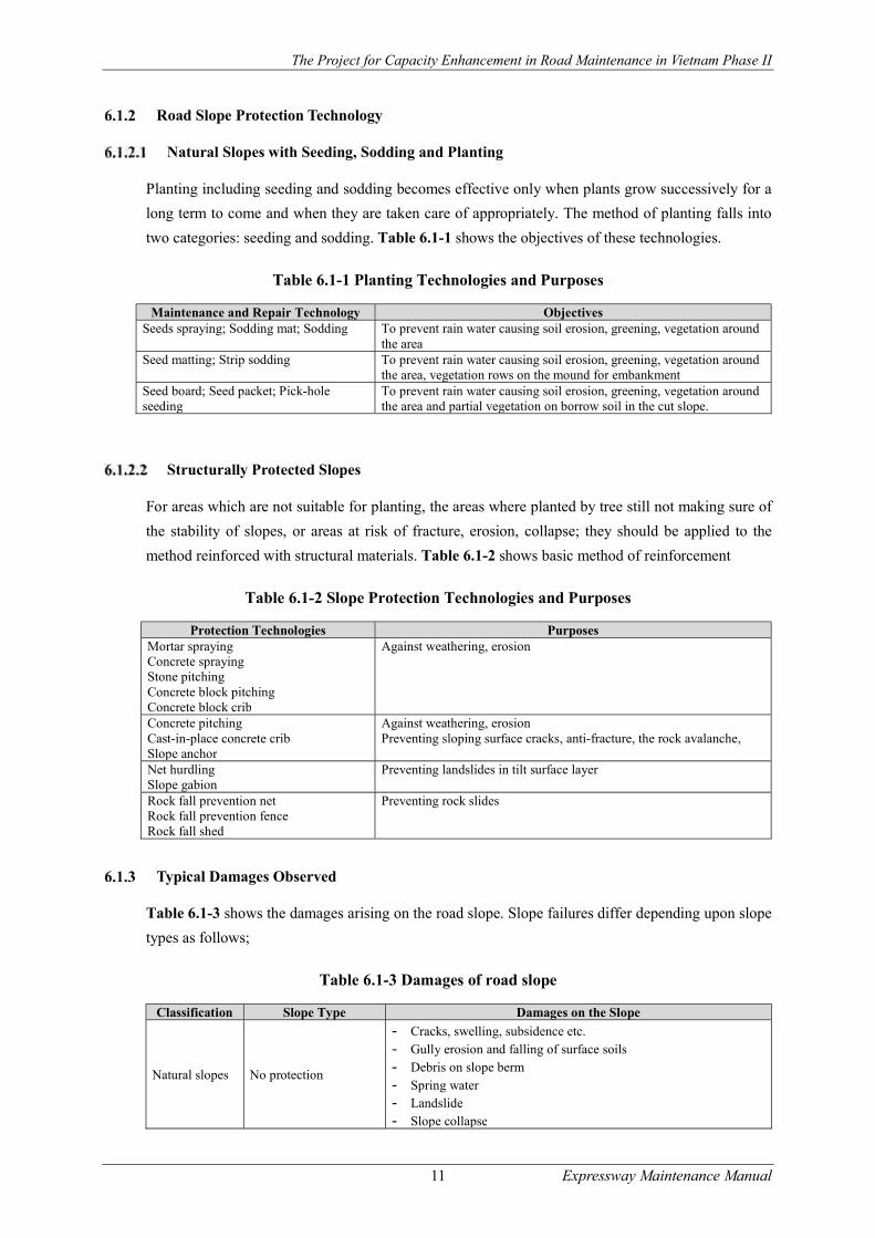
Typical Damages Observed
Table 6.1-3 shows the damages arising on the road slope. Slope failures differ depending upon slope
types as follows;
Table 6.1-3 Damages of road slope
Classification Slope Type Damages on the Slope
Natural slopes No protection
- Cracks, swelling, subsidence etc. - Gully erosion and falling of surface soils - Debris on slope berm - Spring water - Landslide - Slope collapse

The Project for Capacity Enhancement in Road Maintenance in Vietnam Phase II
12 Expressway Maintenance Manual
Classification Slope Type Damages on the Slope
Natural slopes with planting or seeding
- Withered plants and grass - Land slide - Slope collapse
Structurally protected slopes
Stone rip-rap, concrete crib work and stone pitching
- Back filling soil flowing - Holes or cave-in in protected slope - Fall of pebbles or crushed stone in the crib works - Sliding, subsidence, bulging or cracking of concrete crib work - Water seepage or spring water - Erosion of foundation
Concrete or mortar splay
- Cracking and peeling - Swelling and settlement - Water seepage or spring water
Slope wire net - Wire corrosion or rapture - Deformation
Wire cylinder or mat gabion masonry
- Wire corrosion - Falling rocks
Rock fall prevention work
- Weathering and damage of foundation - Accumulation soil and falling rocks - Corrosion of net and straps - Loosen or missing anchor
Inspection of Road Slope
The Guideline regulates the major points of road slope inspection as shown below. For other points
including “Inspection methods and frequencies”, Evaluation of inspection results” and “Data
registration and reporting”, users are requested to refer to the relevant Chapter “Inspection”.
Focus points of inspection
Inspection points
Slopes with structural protection
Monitoring methods of slope damage
Focus Points of Inspection
(1) It is known that general cut slope without protection is weathered and deteriorated and eventually
becomes weakened as time passes by during road maintenance, so that it is important not to miss
the first symptom of slope failure by facility inspection.
(2) Focus points of slope inspection are as follows;
Status of underground and surface water on the slope
Erosion caused by underground or surface water flow
Cracks, swelling and uneven settlement of natural and planting slopes
Cracks, swelling and uneven settlement of structurally protected slopes
Status of growth for planting and seeding slope
In case detecting any slope failures, detailed study shall be implemented immediately for planning
slope protections and evaluating the urgency of countermeasures.

The Project for Capacity Enhancement in Road Maintenance in Vietnam Phase II
13 Expressway Maintenance Manual
(3) Cut slope cracks emerging on the slopes and forward swelling of cut slopes are the main symptoms
of imminent slope failures. Cut slope failures often occur from the upper part of slopes including cut
shoulders, so that it is necessary to investigate the existence of cracks in a wider area including
natural slopes surrounding the cut slopes under consideration.
(4) Attention should be paid to any spring water seen on the cut slope and water treatment on the cut
shoulders, as heavy rainfall may raise ground water level near the slope and have negative effects
on the stability of cut slopes. Care should be directed to any changes of water near the cut slopes
including occurrence of spring water, water volume and turbidity,
(5) Block masonries and concrete frames on the slope often show the first symptom of slope failures, so
that it is particularly important to check for deformation of these structures.
(6) Road embankment constructed with half cutting and half fill on the narrow inclined valleys in the
mountainous area should be carefully inspected as rainfalls often causes high concentrations of water
in the narrow valleys which has negative effects on the embankment.
(7) Any changes seen on the surface of the embankment, such as cracks on the slope shoulder,
differences in level or swelling, should be carefully inspected.
(8) Attention should also be paid on whether plants or grasses fully cover the slopes or whether soil
erosion has occurred.
(9) If urgent countermeasures are needed to ensure stability of the embankment by inspection,
appropriate measures including the installation of drain borings should be implemented to drain out
water from embankments.
(10) The focus points of embankment and cut slope inspection are shown in Figure 6.1-1 and Figure
6.1-2.
Figure 6.1-1 Focus Points of Inspection on Embankment Slopes
The Project for Capacity Enhancement in Road Maintenance in Vietnam Phase II
14 Expressway Maintenance Manual
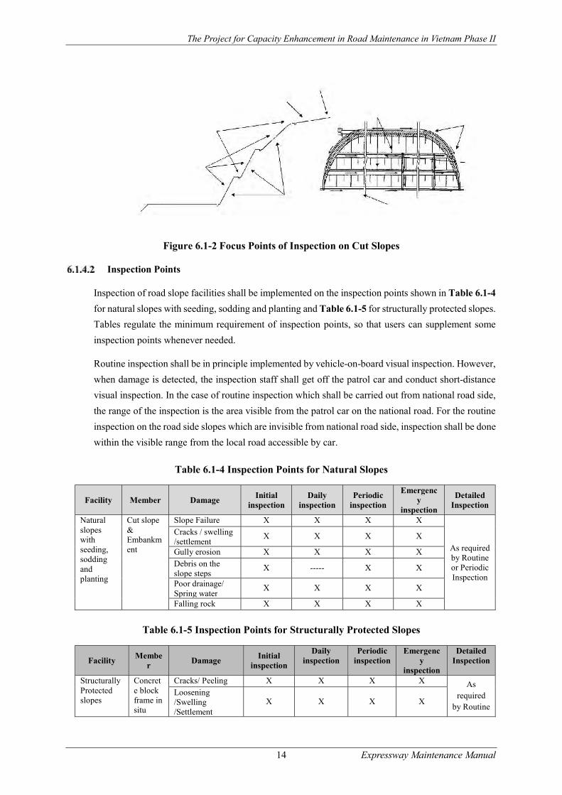
Figure 6.1-2 Focus Points of Inspection on Cut Slopes
Inspection Points
Inspection of road slope facilities shall be implemented on the inspection points shown in Table 6.1-4
for natural slopes with seeding, sodding and planting and Table 6.1-5 for structurally protected slopes.
Tables regulate the minimum requirement of inspection points, so that users can supplement some
inspection points whenever needed.
Routine inspection shall be in principle implemented by vehicle-on-board visual inspection. However,
when damage is detected, the inspection staff shall get off the patrol car and conduct short-distance
visual inspection. In the case of routine inspection which shall be carried out from national road side,
the range of the inspection is the area visible from the patrol car on the national road. For the routine
inspection on the road side slopes which are invisible from national road side, inspection shall be done
within the visible range from the local road accessible by car.
Table 6.1-4 Inspection Points for Natural Slopes
Facility Member Damage Initial
inspection Daily
inspection Periodic
inspection
Emergency
inspection
Detailed Inspection
Natural slopes with seeding, sodding and planting
Cut slope & Embankment
Slope Failure X X X X
As required by Routine or Periodic Inspection
Cracks / swelling /settlement
X X X X
Gully erosion X X X X
Debris on the slope steps
X ----- X X
Poor drainage/ Spring water
X X X X
Falling rock X X X X
Table 6.1-5 Inspection Points for Structurally Protected Slopes
Facility Membe
r Damage
Initial inspection
Daily inspection
Periodic inspection
Emergency
inspection
Detailed Inspection
Structurally Protected slopes
Concrete block frame in situ
Cracks/ Peeling X X X X As required
by Routine
Loosening /Swelling /Settlement
X X X X

The Project for Capacity Enhancement in Road Maintenance in Vietnam Phase II
15 Expressway Maintenance Manual
Facility Membe
r Damage
Initial inspection
Daily inspection
Periodic inspection
Emergency
inspection
Detailed Inspection
/Concrete frame
Spring water/ Poor drainage
X X X X or Periodic Inspection
Mortar spray Concrete spray
Cracks/ Peeling X X X X Loosen / Swelling /Settlement
X X X X
Void X X X X Spring water/ Poor drainage
X X X X
Masonries Concrete Block Masonries
Cracks/ Swelling/ Loosening
X X X X
As required
by Routine or Periodic Inspection
Settlement/ Movement/ Leaning
X X X X
Scouring X X X X Poor drainage or spring water
X X X X
Slope gabion works
a. Steel wire rupture or corrosion
X X X X
b. Deformation X X X X
Inspection Methods and Frequencies
Inspection methods and inspection frequencies in principle shall follow the relevant articles of this
guideline.
Evaluation of Inspection Results
Evaluation of the inspection results obtained in routine inspection, periodic inspection and emergency
inspection shall be conducted, following relevant articles in this guideline. Sample criteria of
inspection results for general slopes and protected slopes are shown in ANNEX-A. Also, particular
notes for the evaluation of some major damages are described below;
(1) Slope failure of general cut slope gives serious damages to road facility and vehicle traffic, so that it
is important not to miss the first symptom of slope failure by facility inspection. When any changes
or damages are found on the cut slope such as small collapse, cracks, swelling, spring water and so
forth, it is necessary to conduct monitoring of these changes, in particular for those which are
expanding and progressing.
(2) Slope damages which lead to slope failure often appear at the upper part of the cut slope due to heavy
rain in the form of tensile cracks or depression. These damages have high potential for large scale
slope failures.
(3) Damages appearing on the structural slope protection are sometimes caused by the damages
occurring in the background area, so that inspection area should be carefully selected in order not to
miss the main causes of the damages.
Registration of Inspection Data and Reporting
Registration of inspection data and reporting shall be conducted, following relevant articles in this
guideline.
The Project for Capacity Enhancement in Road Maintenance in Vietnam Phase II
16 Expressway Maintenance Manual
Planning and Implementation of Maintenance and Repair Work
Introduction
Natural slopes become deteriorated as time passes by due to the weathering of slope soils. Based on
the evaluation results of road slope inspection specified in the previous section, maintenance and repair
works shall be selected for routine maintenance and periodic repair works.
Maintenance and Repair Works
(1) Seepage of underground water
- When underground and surface water may have a potential of causing slope collapse or
slope erosion, drainage system shall be properly installed to lead water to the downstream
drains.
(2) Slope collapse or erosion
- When there are symptoms of slope collapse or erosion, slope protection work shall be
selected and implemented together with planting.
- When planting tree to overcome the erosion area, or landslide, the time of implementation
and the plant environment are limited that it should be noted about selection of planting
technology and crop plants accordingly.
(3) Falling rocks
- When there is a potential hazard of falling rocks in the rainy season, installation of disaster
prevention facilities including a wire net and a rock fall prevention wall is needed
(4) Maintenance of sods and plants
- After the completion of covering with vegetation, it needs about 2 to 3 years that leaves,
old twigs are decayed into nutrients for plants growing in that period, and the plants should
be fertilized at least once a year.
- For the short grasses such as wild sod, korai sodding and Bermuda grass, tall grasses should
be removed for better sunshine.
- When planting in hot and dry season, sun light can dry and cause adverse effects to the
seeds, so sprouts need to be fully watered until seeds are fully developed.
- It’s difficult for plants to develop at the top area that they require more fertilizers and more
care.
- If plants grow slowly, there will be high potential of erosion in the rainy season. Therefore,
the watering and fertilizer should be added when plans grow so slowly in particular in the
hot season.
- At the place where plant and/or grass have been withered, the damaged areas should be
excavated and replaced by the new plant and/or grass at suitable season of growing.
The Project for Capacity Enhancement in Road Maintenance in Vietnam Phase II
17 Expressway Maintenance Manual
(5) Large-scale slope failure
In case slope failure is a large-scale, slope protection shall be planned and implemented in accordance
with the guideline shown in the relevant paragraphs of this Guideline.
(6) Potential hazard of large-scale slope failures or landslides
In case there is a potential hazard of landslide, it is necessary to conduct monitoring and conduct a
further investigation on the slope movement. In particular, if negative effects on the vehicle traffic in
this section is expected to occur, immediate actions shall be taken in particular to ensure the safety of
vehicle traffic. Measures to be taken under this situation are shown below;
- To conduct a detailed survey on the causes and on the expected countermeasures against
slope failures.
- To install monitoring devices to investigate slope movement.
- To guide spring water to the downstream drainage system. Landslides have very close
relation with water permeability and often occur in the area where rainwater concentration
occurs.
- To install measures against slope failures and minimize their effect, including counter
weight embankment, stacked soil sack, net hurdling, gabion work, rock falling prevention
work etc.
(7) Large-scale failures and landslide
When large-scale failures and landslide occurs, road administrator shall take the following actions;
- Emergency maintenance team shall be mobilized to the sites with equipment such as
excavator, motor grader and/or bulldozer as soon as possible to clean debris.
- To control traffic, if necessary.
- To implement temporary countermeasures to minimize the effect on the vehicle traffic.
- To implement further investigation to find out the most appropriate countermeasures,
- To implement permanent countermeasures based on the detailed study.
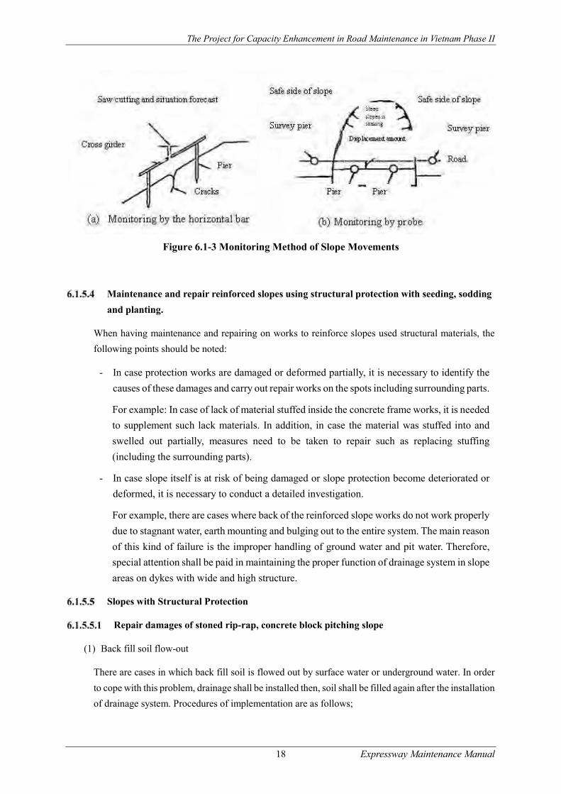
Monitoring of Large-scale Slope Damage
When detecting potential danger leading to serious damages such as landslides later on, it is necessary
to conduct monitoring and keep watching slope movement. A way of monitoring is to install
monitoring devices as shown below such as the installation of strings or piers which shall perform as
a base of measurement and to measure the relative position of slope movement (Figure 6.1-3).
The Project for Capacity Enhancement in Road Maintenance in Vietnam Phase II
18 Expressway Maintenance Manual
Figure 6.1-3 Monitoring Method of Slope Movements
Maintenance and repair reinforced slopes using structural protection with seeding, sodding
and planting.
When having maintenance and repairing on works to reinforce slopes used structural materials, the
following points should be noted:
- In case protection works are damaged or deformed partially, it is necessary to identify the
causes of these damages and carry out repair works on the spots including surrounding parts.
For example: In case of lack of material stuffed inside the concrete frame works, it is needed
to supplement such lack materials. In addition, in case the material was stuffed into and
swelled out partially, measures need to be taken to repair such as replacing stuffing
(including the surrounding parts).
- In case slope itself is at risk of being damaged or slope protection become deteriorated or
deformed, it is necessary to conduct a detailed investigation.
For example, there are cases where back of the reinforced slope works do not work properly
due to stagnant water, earth mounting and bulging out to the entire system. The main reason
of this kind of failure is the improper handling of ground water and pit water. Therefore,
special attention shall be paid in maintaining the proper function of drainage system in slope
areas on dykes with wide and high structure.
Slopes with Structural Protection
Repair damages of stoned rip-rap, concrete block pitching slope
(1) Back fill soil flow-out
There are cases in which back fill soil is flowed out by surface water or underground water. In order
to cope with this problem, drainage shall be installed then, soil shall be filled again after the installation
of drainage system. Procedures of implementation are as follows;
The Project for Capacity Enhancement in Road Maintenance in Vietnam Phase II
19 Expressway Maintenance Manual
- Remove wet or flowed back filling soil
- Provide appropriate drainage system
- Replace new back fill soil by appropriate materials (well-graded soil, sand.) and compact
to required density.
(2) Holes or cave-in in protected slope
Holes or cave-in in protected slope can be failures of slope constructions. It also can results from back
filling soil flowing. The treatment solution for the first case is holes filling by suitable materials of
cement mortar and stones and crushed stone and for the later one is similar with back filling soil
flowing treatments as stated above. The general procedure for the first case is:
- Remove loose materials of stabilized slope
- Fill holes and cave-in by appropriate size stone and pitching by mortar.
- Cleaning and maintaining finished surface of treated slope
(3) Flow out of rubbles and crushed stone filled in the concrete block pitting
Fall of rubbles, crushed stone etc. filled in the stone pitching, concrete block pitching slope may occur
by weathering which lead to slope instability. Countermeasure against these damages is to place new
materials to the damaged area.
(4) Sliding, subsiding, bulging or cracking of slope protection
The protected slope may have problems like sliding, subsidence, bulging or cracking due to various
causes including improper design or failure during construction stage. This problem is more often seen
on the steeper slope. Improper compaction of back fill soil sometimes causes sliding, bulging and
cracking of slope protection facilities.
The single crack of concrete block is deemed independent from subsidence, thus it can be sealed by
cement mortar or by bitumen. Replacement of new concrete block shall be applied when concrete
block has been cracked or broken.
Implementation of repair works against the sliding of slope protection is as follows;
- Remove sliding stones, concrete block and soil.
- Excavate slope to designed shape (design stable slope or grades)
- Compact slope to the level of quality requirement
- Re-stabilize slope as original design
Implementation of repair works against bulging, cracking caused by subsidence is as follows;
- Excavate subsidence, bulging or cracking areas, and remove excavating materials
- Compact slope to designed slope and density
The Project for Capacity Enhancement in Road Maintenance in Vietnam Phase II
20 Expressway Maintenance Manual
- Re-stabilize slope as original design
(5) Groundwater seepage and rainwater infiltration into protected slope or slope foundation
The water seepage from the surface of stabilized slope shall be treated properly. It is necessary to
install drainage system and guide water out of the slope. Implementation of repair works of water
treatment is as follows;
- Check for source of water seepage from the slope and provide appropriate drainage system
- Replace stabilized slope of rip-rap stones or concrete blocks when necessary at provided
drainage system area.
Repair damages of concrete crib works
Concrete crib works shall be damaged due to subsidence of back fill material or erosion/sliding of
back fill soil. Also, improper construction often causes the swelling of back fill materials and then
cracks on the concrete cribs. Poor concrete construction induce water penetration into concrete crib
works, thereby results in the corrosion of reinforcing steel.
(1) Disassemble concrete crib or broken concrete crib due to subsidence
Damages concrete crib works shall be removed and replaced with new crib works. The following
shows implementation methods;
- Remove dissemble and broken part of concrete crib by hammer.
- Repair or replace reinforcing steel, connect new reinforcing steel with origin system by
appropriate method
- Prepare framework of concrete crib
- Pouring concrete as designed concrete mix and maintain in required time
(2) Erosion or sliding of fill back soil
When erosion or sliding occurred at back of concrete crib, the eroded or sliding materials need to be
removed then refilled back by appropriate materials
(3) Cracked and/or swelled out of concrete cribs
- Remove wet or swelled back fill soil
- Break and remove cracked and/or swelled concrete cribs
- Prepare framework of concrete crib
- Pouring concrete as designed concrete mix and maintain in required time
- Refill soil into back of concrete crib works
(4) Reinforcing steel corrosion
Corroded reinforcing steel shall be replaced by following procedure:

The Project for Capacity Enhancement in Road Maintenance in Vietnam Phase II
21 Expressway Maintenance Manual
- Break and remove cracked and/or swelled concrete cribs
- Prepare framework of concrete crib
- Pouring concrete as designed concrete mix and maintain in required time
- Refill soil into back of concrete crib works
Repair damages on the mortar or concrete sprayed slope
Mortal or concrete sprayed slope shall be damaged by underground water seepage, by swelled backfill
soil or improper compaction during construction. In particular, underground water or rain water
infiltration shall cause the bulging and the cracking of mortar or concrete protection slope. Also,
damages shall be caused by damaged drain system on the slope.
Repair works in compliance with damage types are shown below;
(1) Depression, bulging and cracking
- Break and remove damaged mortar area
- Remove wet or swelled back fill soil
- Re-fill back soil and compact to required density
- Re-mortar slope surface
(2) Water seepage
- Break and remove damaged area near seepage position (if any)
- Remove wet or swelled back fill soil
- Check existing drainage system and provide appropriate drainage system if necessary
- Re-fill back soil and compact to required density
- Re-mortar slope surface
(3) Drainage system damages
Repair drainage system (as in 5.3 Section)
Repair damages of grid-frame or slope protection net
Repair works in compliance with damage types are shown below;
(1) Damages of foundation due to weathering
- Check damages of foundation for slope protection net. Depending on the foundation materials,
damages shall be repaired by methods stated in the sections relevant to retaining wall
maintenance and repair.
(2) Piling of soil, gravel, stone debris at slope foundation caused by sliding and erosion

The Project for Capacity Enhancement in Road Maintenance in Vietnam Phase II
22 Expressway Maintenance Manual
- Clear foundation from agglomerated soil and debris.
- Clear drains near foundation of slope protection net
(3) Collapse or corrosion of stakes, piles or pillars
- Clean corroded piles or pillars of net foundation and repainting the piles or pillars
- Cut/ remove broken plies, strengthen the piles or pillars by welding or an appropriate method or
replace the ne pillars
(4) Collapse or corrosion of net or wires
- Clean and paint corroded net
- Cut broken net area, replace and strengthen the net by appropriate material
(5) Disassemble of bolt or dowel
- Remove damaged bolt or dowels and replace by new one
Planning and Implementation of Emergency Repair Work
The following are a few cases of typical urgent repair works against landslide.
(1) Repair works against landslide occurring at upper slopes
In case cracks or damages are observed on the surface of soil layer as shown in
Figure 6.1-4, it is necessary to evaluate hazard risks to vehicle traffic first and take traffic control
measures if needed. If damage is partial and there is no risk of immediate failure, simple
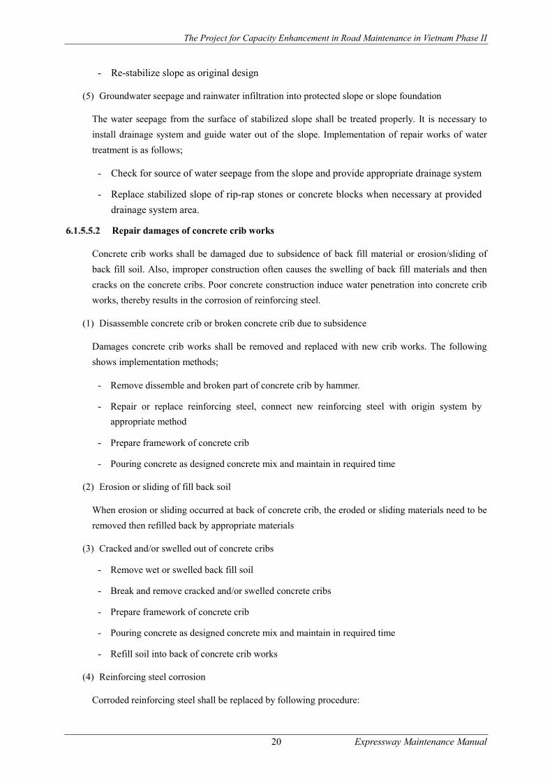
countermeasures shown in
Figure 6.1-5 shall be applied. In case there is a potential risk of large-scale landslides and local
countermeasures cannot be applied, it is necessary to apply long-term safety measures such as re-
cutting of the slopes and the mitigation of slope inclination.
Figure 6.1-4 Landslide at the upper slopes
The Project for Capacity Enhancement in Road Maintenance in Vietnam Phase II
23 Expressway Maintenance Manual
Figure 6.1-5 Simple countermeasures to protect natural slope
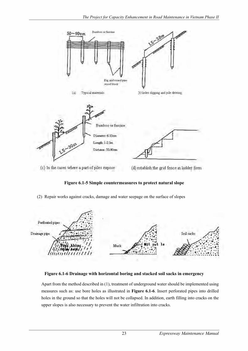
(2) Repair works against cracks, damage and water seepage on the surface of slopes
Figure 6.1-6 Drainage with horizontal boring and stacked soil sacks in emergency
Apart from the method described in (1), treatment of underground water should be implemented using
measures such as: use bore holes as illustrated in Figure 6.1-6. Insert perforated pipes into drilled
holes in the ground so that the holes will not be collapsed. In addition, earth filling into cracks on the
upper slopes is also necessary to prevent the water infiltration into cracks.

The Project for Capacity Enhancement in Road Maintenance in Vietnam Phase II
24 Expressway Maintenance Manual
(3) Repair works against cracks or damages in the lower part of the slopes with underground water
seepage
Where the landslide is big, it should be studied carefully how the damages in the lower part of the
slopes may influence on the upper slope stability. If attention is not paid, rain water infiltration
sometimes causes large-scale landslides. In case potential hazard is detected, temporary works against
expected landslide shall be implemented in the field, such as piling of soil sacks at the foot of the slope
until long-term countermeasures should be applied such as installation of gabion, wood piles, etc. In
the cases that the stability for the entire slope cannot be ensured, re-shaping of cut slope shall be
implemented.
(4) Repair works against falling rocks
In case rocks on the slopes are likely to fall down to the ground, it is necessary to immediately remove
floating rocks or take rock erosion control measures, such as the installation of a concrete grid and a
steel rock net on the slopes.
(5) Repair works against the weathering or the deterioration of slopes protected by mortar spray
It is necessary to partially reinforce the slope with concrete or precast concrete frame, or with other
measures such as using grid to prevent the rolling stone in the case that the drainage system of the
mortar sprayed slopes becomes weak after a long period of time due to the piling of mud, garbage,
grass clog etc. In the case of major damage and big steep slopes, in-situ concrete slope protection
works should be implemented (Figure 6.1-7, Figure 6.1-8).
Figure 6.1-7 Cross section of collapse of mortar stabilized slope
The Project for Capacity Enhancement in Road Maintenance in Vietnam Phase II
25 Expressway Maintenance Manual
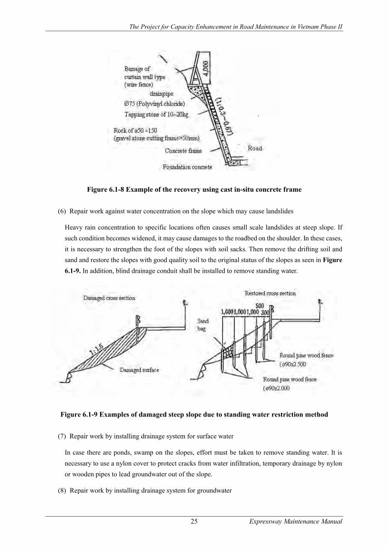
Figure 6.1-8 Example of the recovery using cast in-situ concrete frame
(6) Repair work against water concentration on the slope which may cause landslides
Heavy rain concentration to specific locations often causes small scale landslides at steep slope. If
such condition becomes widened, it may cause damages to the roadbed on the shoulder. In these cases,
it is necessary to strengthen the foot of the slopes with soil sacks. Then remove the drifting soil and
sand and restore the slopes with good quality soil to the original status of the slopes as seen in Figure
6.1-9. In addition, blind drainage conduit shall be installed to remove standing water.
Figure 6.1-9 Examples of damaged steep slope due to standing water restriction method
(7) Repair work by installing drainage system for surface water
In case there are ponds, swamp on the slopes, effort must be taken to remove standing water. It is
necessary to use a nylon cover to protect cracks from water infiltration, temporary drainage by nylon
or wooden pipes to lead groundwater out of the slope.
(8) Repair work by installing drainage system for groundwater
The Project for Capacity Enhancement in Road Maintenance in Vietnam Phase II
26 Expressway Maintenance Manual
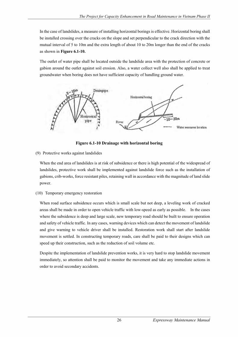
In the case of landslides, a measure of installing horizontal borings is effective. Horizontal boring shall
be installed crossing over the cracks on the slope and set perpendicular to the crack direction with the
mutual interval of 5 to 10m and the extra length of about 10 to 20m longer than the end of the cracks
as shown in Figure 6.1-10.
The outlet of water pipe shall be located outside the landslide area with the protection of concrete or
gabion around the outlet against soil erosion. Also, a water collect well also shall be applied to treat
groundwater when boring does not have sufficient capacity of handling ground water.
Figure 6.1-10 Drainage with horizontal boring
(9) Protective works against landslides
When the end area of landslides is at risk of subsidence or there is high potential of the widespread of
landslides, protective work shall be implemented against landslide force such as the installation of
gabions, crib-works, force resistant piles, retaining wall in accordance with the magnitude of land slide
power.
(10) Temporary emergency restoration
When road surface subsidence occurs which is small scale but not deep, a leveling work of cracked
areas shall be made in order to open vehicle traffic with low-speed as early as possible. In the cases
where the subsidence is deep and large scale, new temporary road should be built to ensure operation
and safety of vehicle traffic. In any cases, warning devices which can detect the movement of landslide
and give warning to vehicle driver shall be installed. Restoration work shall start after landslide
movement is settled. In constructing temporary roads, care shall be paid to their designs which can
speed up their construction, such as the reduction of soil volume etc.
Despite the implementation of landslide prevention works, it is very hard to stop landslide movement
immediately, so attention shall be paid to monitor the movement and take any immediate actions in
order to avoid secondary accidents.

The Project for Capacity Enhancement in Road Maintenance in Vietnam Phase II
27 Expressway Maintenance Manual
Drainage System Maintenance Management
Introduction
Many damages of road facilities are often caused by improper treatment of water, so maintenance and
repair of drainage systems is of critically important.
Classification of Drainage Systems
Drainage facilities in general falls into the following classifications. Figure 6.2-1 illustrates overall
road drainage systems.
a. Road surface drainage system
Road surface drainage system is to prevent the degradation of subgrade bearing capacity which is the
softening of subgrade caused by rain.
b. Underground drainage system
Underground drainage system is to prevent underground water infiltration into road structure from
nearby area.
c. Road Slope drainage system
Road slope drainage system is to treat rain water or underground water and to prevent damages caused
by them.
d. Transverse drainage system
Transverse drainage system is to guide water crossing under road structure.
e. Water discharge drainage
Downstream water outlet is to collect water from road area and discharge water to the drainage system
prepared outside of road area.
Figure 6.2-1 Overall Road Drainage Systems
(1) Road surface drainage system

The Project for Capacity Enhancement in Road Maintenance in Vietnam Phase II
28 Expressway Maintenance Manual
Road surface drainage system shall be classified into the following major facilities;
a. Naked ditch
b. Stone masonry ditch
c. Concrete block masonry ditch
d. Concrete L-shaped ditch
e. Concrete U-shaped ditch
f. Rolled gutter
g. Concrete cast-in-place ditch
(2) Underground drainage System (Figure 6.2-2)
There are mainly three types of underground drainage systems as follows;
a. Underground drainage system is to prevent water infiltration into road body from neighbor
areas and lead water to downstream outlet.
b. Transverse drainage system crossing over road facility
c. Filter layer installed when groundwater level is high to prevent water infiltration into road body
Figure 6.2-2 Underground Drainage System
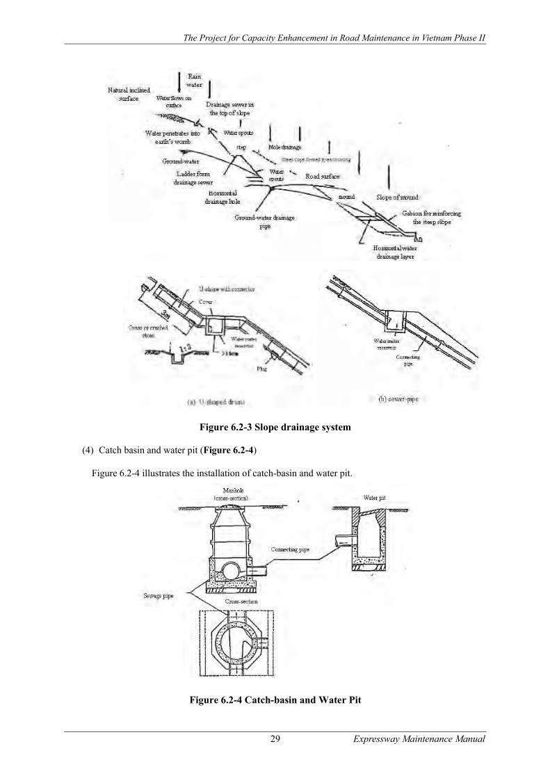
(3) Road Slope Drainage System
There are mainly four types of slope drainage systems available as shown below. Figure 6.2-3
illustrates the installation of rod slope drainage system.
a. Slope shoulder drainage system installed at the top of slope
b. Vertical drainage installed along slope gradient from top to downward
c. Drainage system installed on berms
d. Stone filled drain installed horizontally
The Project for Capacity Enhancement in Road Maintenance in Vietnam Phase II
29 Expressway Maintenance Manual
Figure 6.2-3 Slope drainage system
(4) Catch basin and water pit (Figure 6.2-4)
Figure 6.2-4 illustrates the installation of catch-basin and water pit.
Figure 6.2-4 Catch-basin and Water Pit

The Project for Capacity Enhancement in Road Maintenance in Vietnam Phase II
30 Expressway Maintenance Manual
Typical Damages Observed
Road Surface Drainage System
The following damages are often observed on the road surface drainage system:
- Interruption of water flow due to fallen plants, fallen trees, debris, loose silt or rocks.
- Piling of debris due to insufficient gradient of drainage system
- Pavement surface cracks near road surface drainage system
- Water overflow and puddle due to insufficient gradient or capacity of drainage system
- Water flowing into road surface from surrounding area
- Soil erosion at invert or on the sides of drain due to steep gradient
- Soil erosion at drain exit due to steep water flow
The following are the typical damages for cast-in-place concrete drainage system;
- Cracks or collapse of concrete drain due to the erosion of foundation
- Breakdown of drainage due to high water concentration
- For covered concrete drains, there observed some damages on the drain covers. Concrete
covers are sometimes cracked or broken down due to traffic actions.
Slope Drainage System
The following are the typical damages for slope drainage system;
- Interruption of water flow due to debris in the drains, dense plants, etc.
- Overflow during heavy rain due to low or narrow capacity caused by piled soil, waste and
debris.
- Broken or collapsed drains due to erosion lining
- Damage of joints between drains
Underground Drainage System
The following are the typical damages for underground drainage system;
- Cracks or unevenness on road pavement surface
- Water volume fluctuation at water outlet
Transverse Drainage System
The following are the typical damages for transverse drainage system;
- Cracks and water leakage
- Piling of debris or garbage
The Project for Capacity Enhancement in Road Maintenance in Vietnam Phase II
31 Expressway Maintenance Manual
- Damage of joints and water leakage
- Water puddle due to uneven settlement
- Deterioration of drainage system
Catch-basin and Water Pit
The damages of catch-basin and water pit include the following;
- Physical damages on the facilities
- Piling of debris in the facilities and malfunction of water flow
- Pavement cracks caused by the damages of catch-basin and water pit.
- High concentration of water and overflow from the facilities
Inspection of Drainage Systems
Focus point of inspection
Focus points of inspection are shown below;
(1) Inspection on the drainage systems on the cut slope is important because any change of cut slope
often appears on the drainage systems. Drain systems which are clogged or deformed by debris
induce water infiltration into cut slope and cause slope failure in the long run.
(2) Attention should be paid to any spring water seen on the cut slope and water treatment on the cut
shoulders, as heavy rainfall may raise ground water level near the slope and have negative effects
on the stability of cut slopes. Care should be directed to any changes of water near the cut slopes
including occurrence of spring water, water volume and turbidity.
(3) It is in general very hard to inspect underground drainage systems, so that their functions shall be
inspected after rainfall.
(4) Attention shall be paid to the inspection on whether the drainage systems including outlets and catch-
basis have capacity enough to treat water.
Inspection points
Inspection of road slope facilities shall be implemented on the inspection points shown in Table 6.2-1.
However, the table regulates the minimum requirement of inspection points, so that users can
supplement some inspection points whenever needed.
Routine inspection shall be in principle implemented by vehicle-on-board visual inspection. However,
when damage is detected, the inspection staff shall get off the patrol car and conduct short-distance
visual inspection. In the case of routine inspection which shall be carried out from national road side,
the range of the inspection is the area visible from the patrol car on the national road. For the routine
inspection on the road side drainages which are invisible from national road side, inspection shall be
done within the visible range from the local road accessible by car.
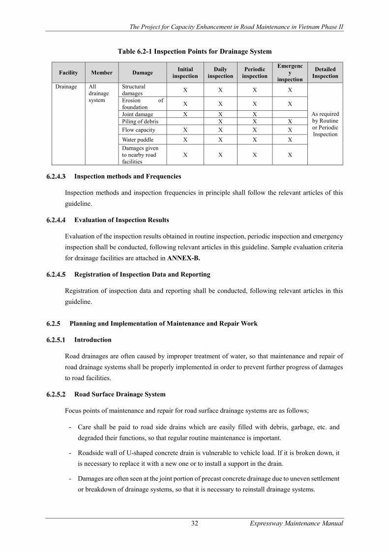
The Project for Capacity Enhancement in Road Maintenance in Vietnam Phase II
32 Expressway Maintenance Manual
Table 6.2-1 Inspection Points for Drainage System
Facility Member Damage Initial
inspection Daily
inspection Periodic
inspection
Emergency
inspection
Detailed Inspection
Drainage All drainage system
Structural damages
X X X X
As required by Routine or Periodic Inspection
Erosion of foundation
X X X X
Joint damage X X X Piling of debris X X X
Flow capacity X X X X
Water puddle X X X X
Damages given to nearby road facilities
X X X X
Inspection methods and Frequencies
Inspection methods and inspection frequencies in principle shall follow the relevant articles of this
guideline.
Evaluation of Inspection Results
Evaluation of the inspection results obtained in routine inspection, periodic inspection and emergency
inspection shall be conducted, following relevant articles in this guideline. Sample evaluation criteria
for drainage facilities are attached in ANNEX-B.
Registration of Inspection Data and Reporting
Registration of inspection data and reporting shall be conducted, following relevant articles in this
guideline.
Planning and Implementation of Maintenance and Repair Work
Introduction
Road drainages are often caused by improper treatment of water, so that maintenance and repair of
road drainage systems shall be properly implemented in order to prevent further progress of damages
to road facilities.
Road Surface Drainage System
Focus points of maintenance and repair for road surface drainage systems are as follows;
- Care shall be paid to road side drains which are easily filled with debris, garbage, etc. and
degraded their functions, so that regular routine maintenance is important.
- Roadside wall of U-shaped concrete drain is vulnerable to vehicle load. If it is broken down, it
is necessary to replace it with a new one or to install a support in the drain.
- Damages are often seen at the joint portion of precast concrete drainage due to uneven settlement
or breakdown of drainage systems, so that it is necessary to reinstall drainage systems.

The Project for Capacity Enhancement in Road Maintenance in Vietnam Phase II
33 Expressway Maintenance Manual
- Underground drainage broken by vehicle load under the ground sometimes causes a serious
problem, subsidence, due to void caused by water leakage. Early detection is a key for successful
maintenance and repair.
The following are the major maintenance and repair methods by damage type.
(1) Interruption of water flow
- Clearing and cleaning drains
(2) Piling of soil
- Cleaning or deepen ditch (de-silting)
- Where deepening is not possible because of topography, new drainage systems shall be
constructed.
(3) Ponding
- Deepen ditch
- Install a new drain.
(4) Unlined drain
- Reshape/regrade ditch, line drain.
(5) Erosion at invert and sides of drain
- Provide erosion control
- Regrade/realign drains,
- Provide repair scour protection,
- Line drain slopes and invert,
- Construct cascade
(6) Erosion at drain outfall
- Provide erosion control of:
- Repair lining,
- Realign drain.
(7) Cracked or broken concrete drain
- Removed damaged concrete block.
- Removed lining materials and wet soil
- Refill and replace new material of drain foundation to correct density
- Install new concrete block of drain and fill joints
(8) Wash-out concrete drain block
The Project for Capacity Enhancement in Road Maintenance in Vietnam Phase II
34 Expressway Maintenance Manual
- Removed lining materials and wet soil
- Refill and replace new material of drain foundation to correct density
- Install new concrete block of drain and fill joints
Road Slope Drainage System
Focus points of maintenance and repair for road slope drainage systems are as follows;
- Road slope damages are often caused by improper treatment of water such as improper guidance
of rain water, water infiltration and water seepage from slope surface etc. It is very important to
lead water to the drainage facilities out of the slope area.
- Road slope drainage is often filled with debris and garbage, so that routine maintenance shall be
done in order to maintain drainage facility in good condition.
- Joints of drainage system, in particular precast concrete facility, are often damaged by uneven
settlement of drainage system, which causes water leakage from broken joints and then soil
erosion shall occur on the foundation of drainage facilities or nearby road structures.
The following are the major maintenance and repair methods by damage type.
(1) Accumulated waste, debris in the drains, at collectors
- Regularly clearing and cleaning drains and collector
(2) Water flow-over during heavy rain
- Clearing and cleaning silted soil, waste and debris or
- Provide new drain line to reduce flow charge or increase capacity of whole slope drain system
(3) Broken drainage facility
- Removed damaged concrete drain
- Removed lining materials and wet soil
- Refill and replace new material of drain foundation to correct density
- Install new concrete block of drain and fill joints
Underground Drainage System
Focus points of maintenance and repair for underground drainage facilities are as follow;
- Underground drainage system is basically unseen from surface, so that attention shall be paid to
their outlet facilities. If damage is detected on their function, maintenance and repair shall be
conducted quickly.
- In case water leakage occurs on the underground drainage due to drainage joint failures, it may
sometimes cause road facility subsidence in the worst case.
- In case inlet of underground drainage facility on the mountain side is filled with debris, fallen

The Project for Capacity Enhancement in Road Maintenance in Vietnam Phase II
35 Expressway Maintenance Manual
trees etc. and does not function well, it may sometimes give serious damages to road structures.
Routine inspection shall be conducted in particular after heavy rainfalls.
- In case water flow function is damages, it is necessary to construct another underground facility
to supplement its capacity.
Catch-basin and Drain Pipes
Focus points of maintenance and repair for catch-basin and water pit facilities are as follow;
- Broken cover of catch-basin may cause traffic accidents, so that early replacement shall be
conducted.
(1) Blocked manhole
- Clear manhole and underground pipes.
(2) Manhole cover or grating is missing or damaged
- Replace manhole cover or grating
(3) The manhole is covered with soil and vegetation
- Clear manhole area.
(4) The catch pit sump is completely silted up
- Clean catch pit sump.
(5) Removed broken or collapsed manhole and pipes
- Removed lining materials and wet soil
- Refill and replace new material of drain foundation to correct density
- Reconstruct manholes and pipes Broken or collapsed manhole or pipes
Road Pavement Maintenance Management
Introduction
Asphalt pavements are worn out due to repeated traffic loading and to the deterioration or aging of the
asphalt mixture, or serviceability deterioration owing to the flow of mixtures or friction.
Typical Damages Observed
Functional Damage and Structural Damage
Damage to asphalt pavements falls into functional damage and structural damage as follows. Table
6.3-1 summarizes damage types which belong to the functional and the structural damages. In addition,
outlines of pavement damages are shown in the next paragraph.
(1) Functional Damage

The Project for Capacity Enhancement in Road Maintenance in Vietnam Phase II
36 Expressway Maintenance Manual
Functional damage, which includes rutting and cracking, is not caused by the reduction of pavement
strength. The damage stays at the surface layer in most of the cases. Unless appropriate repair is made
immediately, the damage gradually progresses into lower layers including binder, subbase course and
base course. Major functional damages include rutting, cracking and the deterioration of skid
resistance. Progress of these damages often causes the deterioration of travel performance in terms of
safety and driving comfort.
(2) Structural Damage
Structural damage is caused by the reduction of pavement bearing capacity of base course or sub grade,
so that it is necessary to consider the repair even of the base and sub grade. Damage related to
pavement structure is caused by strength deterioration under repeated loading, insufficient pavement
thickness and material strength, strength deterioration in the base or sub grade due to frost heave, etc.
Rutting and cracking, which are deemed as the initial stage of functional damages, may also lead to
structural damage if they are left unrepaired for a long time. Structural damage is frequently induced
by strength reduction in lower layers such as the base and sub grade and by the penetration of damage
to lower layers. It is necessary to select the optimal repair method based on the results of structural
surveys of pavements.
Table 6.3-1 Damage Classification
Damage type Status of Damage Observed Damage
Area
Damage Classification
Functional Structural
Rut
ting
Rutting due to the flow of asphalt mixture
Consolidation and lateral movement of asphalt mixture or settlement at lower layers
Mainly on vehicle swept paths along heavy traffic routes in warm areas ○ ○
Rutting due to friction Abrasion on vehicle swept paths
In snowy and cold areas ◎
Cra
ckin
g
Cracking due to the deterioration of bearing capacity of the base and sub grade
Linear cracks developing to hexagonal
Mainly on vehicle swept paths
◎
Cracking due to the deterioration or aging of asphalt mixture
Hexagonal
Cracking occurring on vehicle swept paths progressing to the entire pavement.
○ ○
Cracking due to uneven settlement
Linear (longitudinal, transverse or irregular)
Around the structure, at joints made as a result of the widening of lanes, at cut/fill boundaries, etc.
◎
Cracking due to thermal stress cracking
Linear (transverse). At nearly regular intervals.
In cold areas and in the areas with large variations of temperature
○ ○
Cracking at construction joints
Linear (longitudinal or transverse)
At construction joints
◎
Reflective cracking Liner (longitudinal or transverse)
On concrete slabs and in cases where cement stabilization is applied
◎
Top-down cracking Linear (longitudinal) to reticular
On vehicle swept paths ○ ○
Det
eri
orat
ion
Longitudinal irregularities and settlement
Longitudinal irregularities with a relatively long
In soft grounds, in the backfill of the structure and near a buried object
◎
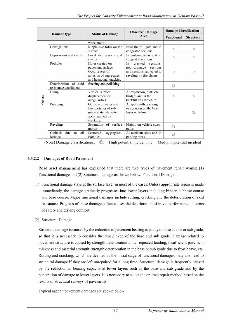
The Project for Capacity Enhancement in Road Maintenance in Vietnam Phase II
37 Expressway Maintenance Manual
Damage type Status of Damage Observed Damage
Area
Damage Classification
Functional Structural
wavelength Corrugations Ripple-like folds on the
surface Near the toll gate and in congested sections
○ ○
Depressions and swells Local depressions and swells
In parking areas and in congested sections
○ ○
Oth
ers
Potholes Holes created on pavement surface. Occurrences of abrasion of aggregates and hexagonal cracking
In cracked sections, poor-drainage sections and sections subjected to raveling by tire chains
○ ○
Deterioration of skid resistance coefficient
freezing and polishing ◎
Bump Vertical surface displacement or irregularities
At expansion joints on bridges and in the backfill of a structure
○ ○
Pumping
Outflow of water and fine particles of sub grade materials, often accompanied by cracking.
At spots with cracking or abrasion on the base layer or below
◎
Raveling Separation of surface mortar
Mainly on vehicle swept paths
◎
Cutback due to oil leakage
Scattered aggregates. Potholes.
At accident sites and in parking areas
◎
(Note) Damage classifications: ◎; High potential incident, ○; Medium potential incident
Damages of Road Pavement
Road asset management has explained that there are two types of pavement repair works; (1)
Functional damage and (2) Structural damage as shown below. Functional Damage
(1) Functional damage stays at the surface layer in most of the cases. Unless appropriate repair is made
immediately, the damage gradually progresses into lower layers including binder, subbase course
and base course. Major functional damages include rutting, cracking and the deterioration of skid
resistance. Progress of these damages often causes the deterioration of travel performance in terms
of safety and driving comfort.
(2) Structural Damage
Structural damage is caused by the reduction of pavement bearing capacity of base course or sub grade,
so that it is necessary to consider the repair even of the base and sub grade. Damage related to
pavement structure is caused by strength deterioration under repeated loading, insufficient pavement
thickness and material strength, strength deterioration in the base or sub grade due to frost heave, etc.
Rutting and cracking, which are deemed as the initial stage of functional damages, may also lead to
structural damage if they are left unrepaired for a long time. Structural damage is frequently caused
by the reduction in bearing capacity at lower layers such as the base and sub grade and by the
penetration of damage to lower layers. It is necessary to select the optimal repair method based on the
results of structural surveys of pavements.
Typical asphalt pavement damages are shown below.

The Project for Capacity Enhancement in Road Maintenance in Vietnam Phase II
38 Expressway Maintenance Manual
(1) Rutting
Rutting is transverse surface deformation created by vehicle loading. Rutting is caused either by the
flow of asphalt mixture or by vehicle loading. Potential external causes of the former rutting, which is
caused by the flow of asphalt mixture, are the rise of pavement surface temperature in the summer
season and the concentration of heavy vehicles on specific lanes. The mechanical properties of asphalt
mixtures are greatly affected by binder properties. Asphalt mixtures behave like an elastic body at low
temperature but they behave like a viscos-elastic body under high temperature. Under high
temperature, asphalt mixtures are vulnerable to deformation caused by heavy vehicles. Deformation
accumulates in the pavement as vehicles run on the same position, thereby becomes permanent
deformation in the pavement. One of the internal factors of the rutting is the flow resistance of asphalt
mixtures. Flow resistance is affected by the amount of asphalt, asphalt penetration and the grain size
of the mixture. Measures to increase flow resistance are listed below.
Minimize the amount of asphalt as long as an optimum amount is secured.
Use hard asphalt.
Use coarse graded materials for mixtures and increase the amount of coarse aggregate.
The external cause of rutting is the travel of vehicles equipped with tire chains or spike tires. A
conceivable internal factor is the frictional resistance of asphalt mixtures. Frictional resistance is
reduced by the following factors.
Inadequate density due to insufficient compaction
Inadequate amount of asphalt
Low hardness of aggregate
Photo Rutting which is caused by the flow of asphalt mixture
Photo Rutting which is caused by vehicle loading
(2) Cracking
Cracking is caused by the deterioration or aging of mixture or by structural factors. Both factors affect
the durability of pavements, so that if cracks are left unrepaired, cracks shall grow day by day.
Infiltration of water contributes to structural damages. Cracking is roughly divided into linear and
planar types. Linear cracking is generally occurs in the initial stage of cracking and mostly belongs to
functional damage. Planar cracking usually occurs as linear cracking and develops with the lapse of
time into structural damage. The most important external cause of cracking is traffic loading. Cracks
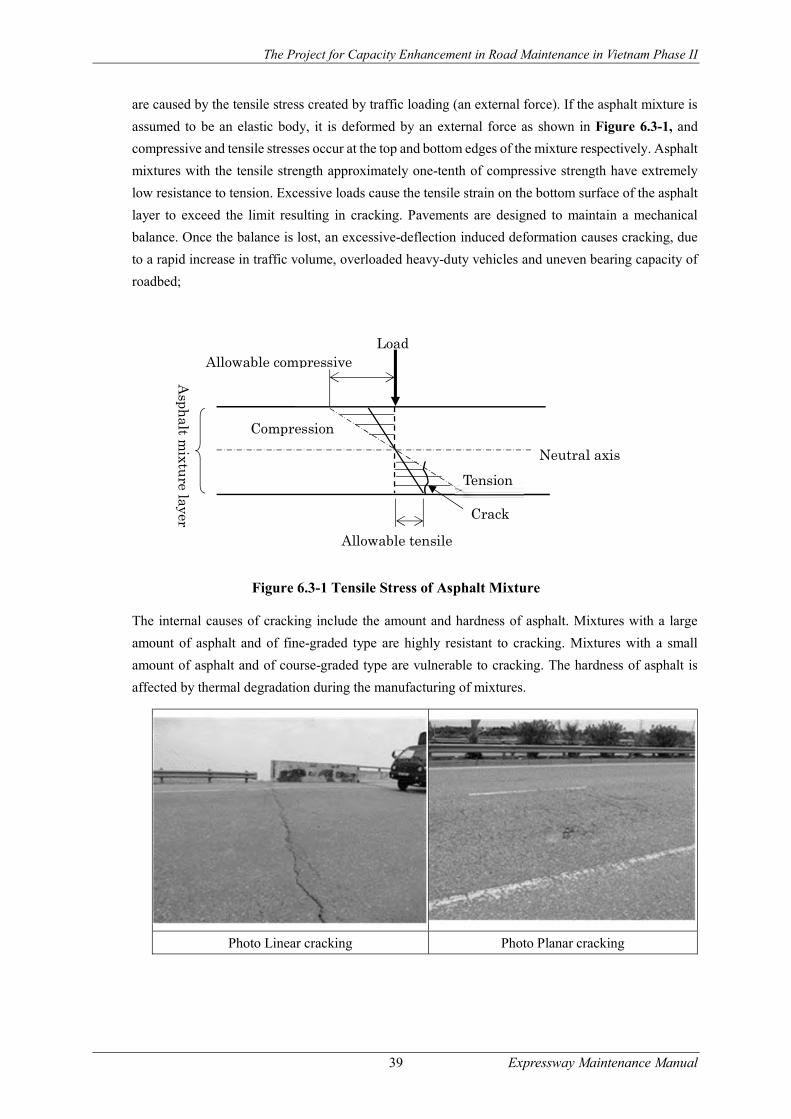
The Project for Capacity Enhancement in Road Maintenance in Vietnam Phase II
39 Expressway Maintenance Manual
are caused by the tensile stress created by traffic loading (an external force). If the asphalt mixture is
assumed to be an elastic body, it is deformed by an external force as shown in Figure 6.3-1, and
compressive and tensile stresses occur at the top and bottom edges of the mixture respectively. Asphalt
mixtures with the tensile strength approximately one-tenth of compressive strength have extremely
low resistance to tension. Excessive loads cause the tensile strain on the bottom surface of the asphalt
layer to exceed the limit resulting in cracking. Pavements are designed to maintain a mechanical
balance. Once the balance is lost, an excessive-deflection induced deformation causes cracking, due
to a rapid increase in traffic volume, overloaded heavy-duty vehicles and uneven bearing capacity of
roadbed;
Figure 6.3-1 Tensile Stress of Asphalt Mixture
The internal causes of cracking include the amount and hardness of asphalt. Mixtures with a large
amount of asphalt and of fine-graded type are highly resistant to cracking. Mixtures with a small
amount of asphalt and of course-graded type are vulnerable to cracking. The hardness of asphalt is
affected by thermal degradation during the manufacturing of mixtures.
Photo Linear cracking Photo Planar cracking
Compression
Allowable tensile
Asph
alt mixtu
re layer
Load
Neutral axis
Tension
Crack
Allowable compressive
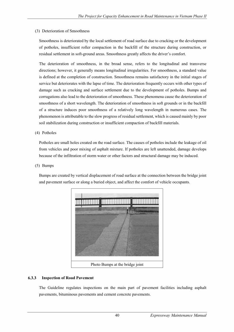
The Project for Capacity Enhancement in Road Maintenance in Vietnam Phase II
40 Expressway Maintenance Manual
(3) Deterioration of Smoothness
Smoothness is deteriorated by the local settlement of road surface due to cracking or the development
of potholes, insufficient roller compaction in the backfill of the structure during construction, or
residual settlement in soft-ground areas. Smoothness greatly affects the driver’s comfort.
The deterioration of smoothness, in the broad sense, refers to the longitudinal and transverse
directions; however, it generally means longitudinal irregularities. For smoothness, a standard value
is defined at the completion of construction. Smoothness remains satisfactory in the initial stages of
service but deteriorates with the lapse of time. The deterioration frequently occurs with other types of
damage such as cracking and surface settlement due to the development of potholes. Bumps and
corrugations also lead to the deterioration of smoothness. These phenomena cause the deterioration of
smoothness of a short wavelength. The deterioration of smoothness in soft grounds or in the backfill
of a structure induces poor smoothness of a relatively long wavelength in numerous cases. The
phenomenon is attributable to the slow progress of residual settlement, which is caused mainly by poor
soil stabilization during construction or insufficient compaction of backfill materials.
(4) Potholes
Potholes are small holes created on the road surface. The causes of potholes include the leakage of oil
from vehicles and poor mixing of asphalt mixture. If potholes are left unattended, damage develops
because of the infiltration of storm water or other factors and structural damage may be induced.
(5) Bumps
Bumps are created by vertical displacement of road surface at the connection between the bridge joint
and pavement surface or along a buried object, and affect the comfort of vehicle occupants.
Photo Bumps at the bridge joint
Inspection of Road Pavement
The Guideline regulates inspections on the main part of pavement facilities including asphalt
pavements, bituminous pavements and cement concrete pavements.

The Project for Capacity Enhancement in Road Maintenance in Vietnam Phase II
41 Expressway Maintenance Manual
Focus Points of Inspection
Pavement inspection are not only to detect pavement damages promptly which may lead to traffic
accidents, but also to obtain data for strategic planning of maintenance and repair works of the road
pavement. The following are the points to be focused on in implementing pavement inspection.
Asphalt Concrete Pavement & Bituminous Surface Treatment
(1) Asphalt pavement cracks induce water infiltration into the pavement body and have a negative effect
on the pavement life-cycle. The following are the points to note in carrying out the inspections.
- Observe pavement cracks from slow moving vehicles on the road shoulder. If needed, stop the
car and conduct a visual observation of the cracks.
- Drying time after rainfall for crack sections is in general much longer than that for the non-crack
sections.
- Brief sketching or photographing crack conditions with measurement scales, which facilitates
the computation of crack rates, will help support the evaluation of the defects and deterioration
of asphalt pavements
(2) Potholes, peeling and depression of asphalt pavement often give a serious influence on drivability,
in particular to motorcycles and cause traffic accidents, so that inspection needs to be conducted with
much attention.
- Observe the magnitude of damages in depth and in width.
- Carefully observe influence on vehicle drivability
(3) Rutting, caused by asphalt flow and abrasion and scattering of aggregate, allows water to puddle and
water splash on the pavement surface, causing a decline in skid resistance and visibility during night
driving. The following are the points to note in carrying out the inspections.
- Observe whether car loses driving control
- Observe steering ability when crossing lanes
- Observe puddles and splash of water when it rains
(4) Longitudinal roughness, when it becomes noticeable, often causes a decline in driving comfort and
increased driving fatigue to vehicle drivers, thereby lowering driving safety. Large longitudinal
corrugations not only cause discomfort to drivers, but cause lateral vibration in the vehicles and thus
impair driving safety. Also, impact load often causes noise and vibration of the pavement, bridge
structures and roadside environment. It is therefore necessary to carry out inspection carefully.
- Observe driving comfort and vibration while driving.
- Observe straightness of guardrails and road markings.
(5) Bumps often appear at the connection with bridges, at the places where there are crossing structures
and at the transition between cut and fill, and often cause big shocks to vehicles. Shocks not only
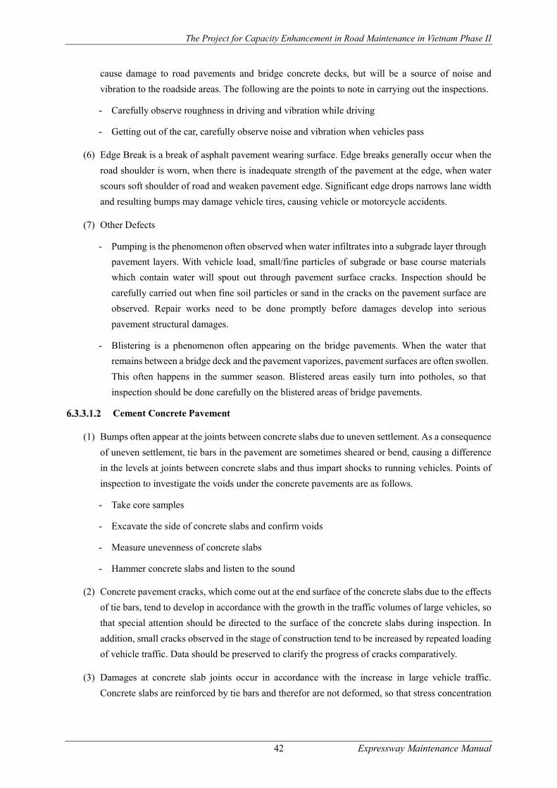
The Project for Capacity Enhancement in Road Maintenance in Vietnam Phase II
42 Expressway Maintenance Manual
cause damage to road pavements and bridge concrete decks, but will be a source of noise and
vibration to the roadside areas. The following are the points to note in carrying out the inspections.
- Carefully observe roughness in driving and vibration while driving
- Getting out of the car, carefully observe noise and vibration when vehicles pass
(6) Edge Break is a break of asphalt pavement wearing surface. Edge breaks generally occur when the
road shoulder is worn, when there is inadequate strength of the pavement at the edge, when water
scours soft shoulder of road and weaken pavement edge. Significant edge drops narrows lane width
and resulting bumps may damage vehicle tires, causing vehicle or motorcycle accidents.
(7) Other Defects
- Pumping is the phenomenon often observed when water infiltrates into a subgrade layer through
pavement layers. With vehicle load, small/fine particles of subgrade or base course materials
which contain water will spout out through pavement surface cracks. Inspection should be
carefully carried out when fine soil particles or sand in the cracks on the pavement surface are
observed. Repair works need to be done promptly before damages develop into serious
pavement structural damages.
- Blistering is a phenomenon often appearing on the bridge pavements. When the water that
remains between a bridge deck and the pavement vaporizes, pavement surfaces are often swollen.
This often happens in the summer season. Blistered areas easily turn into potholes, so that
inspection should be done carefully on the blistered areas of bridge pavements.
Cement Concrete Pavement
(1) Bumps often appear at the joints between concrete slabs due to uneven settlement. As a consequence
of uneven settlement, tie bars in the pavement are sometimes sheared or bend, causing a difference
in the levels at joints between concrete slabs and thus impart shocks to running vehicles. Points of
inspection to investigate the voids under the concrete pavements are as follows.
- Take core samples
- Excavate the side of concrete slabs and confirm voids
- Measure unevenness of concrete slabs
- Hammer concrete slabs and listen to the sound
(2) Concrete pavement cracks, which come out at the end surface of the concrete slabs due to the effects
of tie bars, tend to develop in accordance with the growth in the traffic volumes of large vehicles, so
that special attention should be directed to the surface of the concrete slabs during inspection. In
addition, small cracks observed in the stage of construction tend to be increased by repeated loading
of vehicle traffic. Data should be preserved to clarify the progress of cracks comparatively.
(3) Damages at concrete slab joints occur in accordance with the increase in large vehicle traffic.
Concrete slabs are reinforced by tie bars and therefor are not deformed, so that stress concentration

The Project for Capacity Enhancement in Road Maintenance in Vietnam Phase II
43 Expressway Maintenance Manual
arises at or nearby joint structures between concrete slabs. In general, it is preferable to inspect joints
of concrete pavements in winter, since joints gaps become wider in winter.
Inspection Points
Road facility inspection for pavement facilities shall be implemented on the inspection points shown
in Table 6.3-2.
Table 6.3-2 Inspection Points for Pavement
Facility Member Damage Initial
inspection Routine
inspection Periodic
inspection
Emergency
Inspection
Detail Inspection
Road Pavement
Asphalt Pavement
Pot holes/ Potholes/Peeling/ depressions
X X --- X
As required by Routine or Periodic Inspection
Cracks --- --- XX --- Rutting Depth --- --- XX --- IRI --- --- XX --- Edge Break X X --- X Bumps X X --- X Pumping X X --- X Blistering X X --- X
Concrete pavement
Bumps X X --- X As required by Routine or Periodic Inspection
Cracks --- --- XX --- IRI --- --- XX --- Concrete slab joint damages
X X X X
Road surface drainage system
Damages of drainage facilities
X X X X As required by Routine or Periodic Inspection
Joint damages X X X X Piling of debris X X X X
(Note) X: Inspection items, XX: Inspection items to be measured by pavement condition survey vehicle.
(1) Routine inspection shall detect pavement damages, in particular focusing on the damages causing
unsafety to road traffic such as pot holes, bumps, rutting, water paddle etc.
(2) Periodic inspection shall cover surveys not only on the asphalt concrete pavement, bituminous
surface treatment and cement concrete pavement, but also on the road surface drainage systems.
(3) In case pavement condition survey vehicle is applied to the periodic inspection, it shall measure
pavement condition indexes including crack rate, rut depth and IRIs every 100 meters. Of these
pavement condition indexes, rut depth and IRIs are automatically measures by the on-board sensors,
on the other hand, crack rate shall be manually calculated by analysing video data recorded all the
way during pavement condition survey. Other damages on the concrete slab joint and on the road
surface drainage systems shall be separately inspected by patrol staff, following the relevant above
articles in this guideline.
(4) Periodic inspection by pavement condition survey vehicle shall be conducted by professional
organization designated by DRVN. Managing agency of road facility inspection shall commit the
road condition survey in the region to the professional agency by contract.
(5) Professional organization shall take responsibilities for carrying out the field survey on pavement
conditions, analysing crack data, evaluating the results of inspection, registering data into the
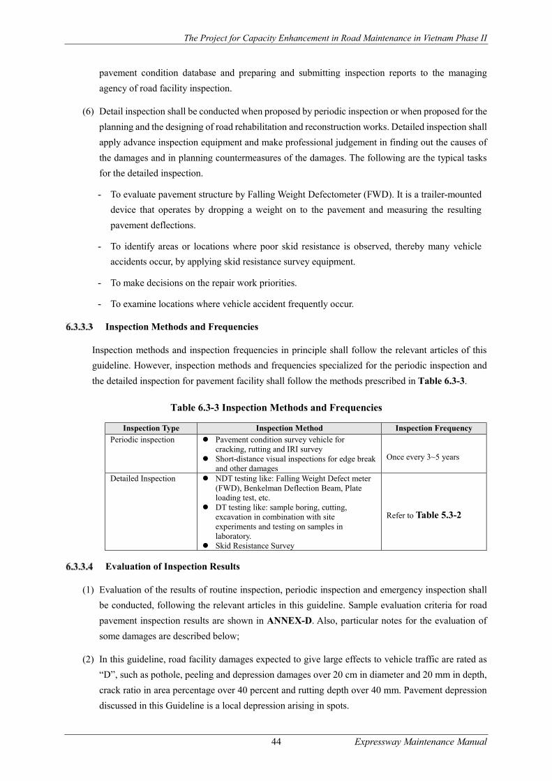
The Project for Capacity Enhancement in Road Maintenance in Vietnam Phase II
44 Expressway Maintenance Manual
pavement condition database and preparing and submitting inspection reports to the managing
agency of road facility inspection.
(6) Detail inspection shall be conducted when proposed by periodic inspection or when proposed for the
planning and the designing of road rehabilitation and reconstruction works. Detailed inspection shall
apply advance inspection equipment and make professional judgement in finding out the causes of
the damages and in planning countermeasures of the damages. The following are the typical tasks
for the detailed inspection.
- To evaluate pavement structure by Falling Weight Defectometer (FWD). It is a trailer-mounted
device that operates by dropping a weight on to the pavement and measuring the resulting
pavement deflections.
- To identify areas or locations where poor skid resistance is observed, thereby many vehicle
accidents occur, by applying skid resistance survey equipment.
- To make decisions on the repair work priorities.
- To examine locations where vehicle accident frequently occur.
Inspection Methods and Frequencies
Inspection methods and inspection frequencies in principle shall follow the relevant articles of this
guideline. However, inspection methods and frequencies specialized for the periodic inspection and
the detailed inspection for pavement facility shall follow the methods prescribed in Table 6.3-3.
Table 6.3-3 Inspection Methods and Frequencies
Inspection Type Inspection Method Inspection Frequency Periodic inspection Pavement condition survey vehicle for
cracking, rutting and IRI survey Short-distance visual inspections for edge break
and other damages Once every 3~5 years
Detailed Inspection NDT testing like: Falling Weight Defect meter (FWD), Benkelman Deflection Beam, Plate loading test, etc.
DT testing like: sample boring, cutting, excavation in combination with site experiments and testing on samples in laboratory.
Skid Resistance Survey
Refer to Table 5.3-2
Evaluation of Inspection Results
(1) Evaluation of the results of routine inspection, periodic inspection and emergency inspection shall
be conducted, following the relevant articles in this guideline. Sample evaluation criteria for road
pavement inspection results are shown in ANNEX-D. Also, particular notes for the evaluation of
some damages are described below;
(2) In this guideline, road facility damages expected to give large effects to vehicle traffic are rated as
“D”, such as pothole, peeling and depression damages over 20 cm in diameter and 20 mm in depth,
crack ratio in area percentage over 40 percent and rutting depth over 40 mm. Pavement depression
discussed in this Guideline is a local depression arising in spots.

The Project for Capacity Enhancement in Road Maintenance in Vietnam Phase II
45 Expressway Maintenance Manual
(3) In case PMS is applied to the formulation of periodic repair plans for road pavement, evaluation on
the inspection results shall be automatically carried out in the computation processes of PMS model.
Other damages shall be separately inspected by patrol staff in the routine inspection and evaluated,
following the relevant above articles in this guideline.
Planning of Maintenance and Repair
Proper maintenance or repair shall restore the performance of asphalt pavements and reduces overall
pavement life cycle costs. In planning maintenance or repair works, the road sections that require
maintenance and repairs need to be selected and prioritized based on the diagnosis of pavement
inspection. Appropriate maintenance and repair works are then selected for these high-priority road
sections. The above process is implemented for each road network and for respective projects. Data
needed for the designing of pavement maintenance and repair plans are shown below.
- Initial design conditions
- Pavement configuration (thickness and material property)
- Pavement management level
- Traffic volume and axle load (wheel load)
- History of maintenance and repair
- Surface property and mixture property
- Load bearing capacity and strength of each layer
Asphalt pavements are anytime exposed to weather changes, so that when damage is discovered on
the pavement, appropriate measures, e.g. crack seal etc., need to be taken in the initial stage of the
damage in order to block water infiltration into pavement layers. Early repair is a key to prolong
pavement life until future large-scale repair. The following outlines the data needed for the planning.
In case that target level of pavement management is promulgated, the pavement management level
shall be taken into consideration in maintenance and repair work selection. Table 6.3-4 shows a
sample pavement management level currently applied to the Inter-city expressway network
management by NEXCO-Central in Japan.
Table 6.3-4 Target Pavement Management Level (Reference)
Rutting (mm)
Faulting Coefficient of
Skid Resistance (μ80)
Longitudinal Roughness
(mm) IRI
Crack Rate (%) Bridge
Approach
Transverse structure approach
25 20 30 0.25 3.5 20
(Note) Target pavement management level: from NEXCO-Central in Japan.
The Project for Capacity Enhancement in Road Maintenance in Vietnam Phase II
46 Expressway Maintenance Manual
Identification of Design Conditions
When planning repair methods, it is necessary to identify design parameters including load bearing
capacity, pavement structure, property of pavement materials and traffic conditions, before going into
the designing or selecting the materials for repair works. It is also necessary to get information on the
design conditions for initial construction and on maintenance and repair history in the past.
(1) Load bearing capacity and pavement structure
Evaluating the load bearing capacity and pavement structure enables the determination of whether the
damage is structural or functional. Estimating the value required for overlay sectional design also
becomes possible. Whenever the degree of deflection is found to be extraordinarily higher than usual,
it often turns out that the sub grade has insufficient load bearing capacity. In those instances, cut and
cover surveys need to be implemented. The depth of layers in which damage prevails and the load
bearing capacity of the sub grade are measured to collect data required for identifying the range of
layers that requires repair and for designing the cross section.
(2) Properties of pavement materials
For asphalt mixtures, the grain size, amount of asphalt and asphalt property are investigated. Water
content and penetration are investigated in the base and sub grade. The material properties of asphalt
mixtures are frequently investigated mainly in the case where the damage is determined to be of
functional type. Then, identifying the asphalt mixture material properties enables appropriate selection
of repair materials.
(3) Traffic loads
Pavements are also damaged in numerous cases as cyclic loading exceeding the design traffic volume
or excessive traffic loads act, breaking the equilibrium between the traffic load and the pavement
structure. In the case of sectional design in the repair of structural damage in particular, it is desirable
to identify not only the sub grade design conditions but also the traffic loads for appropriate sectional
design. In the case of functional damage, grasping the extent of traffic load is also important.
(4) Design conditions for initial construction and history of maintenance and repair
The design conditions when the pavement was initially constructed are important at the time of
sectional design during the repair of structural damage. The history of maintenance and repair is useful
when selecting the repair method or the range of repair.
Selection of Maintenance and Repair Work
The following three-step approach shall be applied to the repair work selection. First, to select standard
repair work, and second to implement detailed survey and review the standard repair work, taking
local conditions into consideration. Each of these approaches will be further discussed in the following
sections.
(1) Select routine maintenance or periodic repair based on the results of inspection.

The Project for Capacity Enhancement in Road Maintenance in Vietnam Phase II
47 Expressway Maintenance Manual
(2) Select standard pavement maintenance and repair work.
(3) Conduct detailed surveys including field observation and additional equipment
surveys such as FWD, Skid Resistance Survey and so forth.
Selection of routine maintenance or periodic repair
The selection of maintenance and repair work shall be done based on the results of road facility
inspection as shown in Figure 5.3-1.
(1) Routine Maintenance
Damages and deterioration evaluated as “E”, which is small-scale, but is to be urgently repaired, shall
be repaired by small repair in the routine maintenance or in the emergency work as early as possible
in order to mitigate the negative effects given to the road traffic and safety. In case damage area for
this repair work shall be fairly limited to the spot or to the narrow range not more than 1.0m x 1.0m,
whose repair work scale is manageable by maintenance patrol staff, small repair in the routine
maintenance shall be applied.
(2) Periodic Repair
Road pavement becomes deteriorated as time passes by even routine maintenance is properly done.
Periodic Repair is a more macroscopic and large-scale measure than routine maintenance to preserve
traffic and road infrastructure functions during the long course of road maintenance. Periodic repair is
a scheduled road asset management activity, focusing on much wider area than routine maintenance
to preserve functions of road transport assets, which cannot be assured by routine maintenance. Work
selection of periodic repair shall be made based on the data obtained by pavement condition survey.
PMS is often employed as a measure to plan annual and medium term (5-Year) periodic repair plans
In the case of periodic repair, damages and deterioration which are evaluated as “C” or “D” shall be
repaired by Periodic Repair, which is planned repair over 5 years with preferential treatment depending
upon ABC rating. In case that damage area is larger than 1.0m x 1.om and widespread, but is rated as
“E” in the diagnosis, repair work shall be incorporated into an annual repair plan and implemented
together with other repair work. In case that damage area is larger than 1.0m x 1.om and widespread,
but is rated as “C” or “D” in the diagnosis, repair work shall be incorporated into Periodic Repair Plan
and implemented over 5 years with preferential treatment depending upon ABC rating.
Selection of Standard Maintenance and Repair Work
Figure 6.3-2 shows the framework to select standard maintenance and repair work for routine
maintenance and periodic repair. Table 6.3-5 shows the outline of these maintenance and repair work.
As seen in the figure and the table, routine maintenance works consist of cutting, crack seal, pothole
repair, surface treatment, bump repair and linear replacement. Also, major periodic repair works
consists of overlay, local replacement, leveling, cut and overlay and replacement. Users are requested
to select standard maintenance and repair work for routine maintenance and periodic repair based on
the figure and the table.
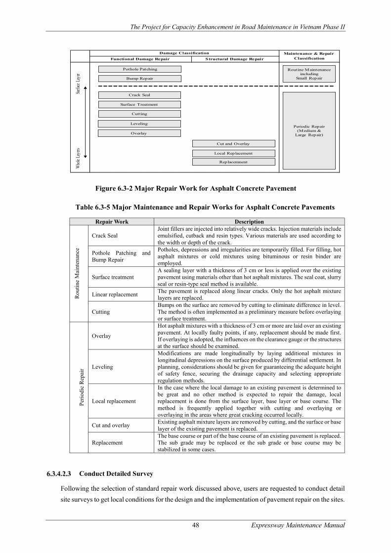
The Project for Capacity Enhancement in Road Maintenance in Vietnam Phase II
48 Expressway Maintenance Manual
Figure 6.3-2 Major Repair Work for Asphalt Concrete Pavement
Table 6.3-5 Major Maintenance and Repair Works for Asphalt Concrete Pavements
Repair Work Description
Rou
tine
Mai
nten
ance
Crack Seal Joint fillers are injected into relatively wide cracks. Injection materials include emulsified, cutback and resin types. Various materials are used according to the width or depth of the crack.
Pothole Patching and Bump Repair
Potholes, depressions and irregularities are temporarily filled. For filling, hot asphalt mixtures or cold mixtures using bituminous or resin binder are employed.
Surface treatment A sealing layer with a thickness of 3 cm or less is applied over the existing pavement using materials other than hot asphalt mixtures. The seal coat, slurry seal or resin-type seal method is available.
Linear replacement The pavement is replaced along linear cracks. Only the hot asphalt mixture layers are replaced.
Cutting Bumps on the surface are removed by cutting to eliminate difference in level. The method is often implemented as a preliminary measure before overlaying or surface treatment.
Per
iodi
c R
epai
r
Overlay
Hot asphalt mixtures with a thickness of 3 cm or more are laid over an existing pavement. At locally faulty points, if any, replacement should be made first. If overlaying is adopted, the influences on the clearance gauge or the structures at the surface should be examined.
Leveling
Modifications are made longitudinally by laying additional mixtures in longitudinal depressions on the surface produced by differential settlement. In planning, considerations should be given for guaranteeing the adequate height of safety fence, securing the drainage capacity and selecting appropriate regulation methods.
Local replacement
In the case where the local damage to an existing pavement is determined to be great and no other method is expected to repair the damage, local replacement is done from the surface layer, base layer or base course. The method is frequently applied together with cutting and overlaying or overlaying in the areas where great cracking occurred locally.
Cut and overlay Existing asphalt mixture layers are removed by cutting, and the surface or base layer of the existing pavement is replaced.
Replacement The base course or part of the base course of an existing pavement is replaced. The sub grade may be replaced or the sub grade or base course may be stabilized in some cases.
Conduct Detailed Survey
Following the selection of standard repair work discussed above, users are requested to conduct detail
site surveys to get local conditions for the design and the implementation of pavement repair on the sites.
Functional Damage Repair Structural Damage Repair
Damage Classification Maintenance & Repair Classification
Crack Seal
Pothole Patching
Surface Treatment
Replacemnent
Local Replacement
Cut and Overlay
Leveling
Routine Maintenance including
Small Repair
Periodic Repair(Medium &
Large Repair)
Surfa
ce L
ayer
Who
le La
yers
Cutting
Bump Repair
Overlay

The Project for Capacity Enhancement in Road Maintenance in Vietnam Phase II
49 Expressway Maintenance Manual
Detail survey may include field visual observation conducted to the damage and deterioration identified
in the pavement inspection. Detail survey shall be done by competent engineers. In addition, further
survey, such as FWD, skid resistance survey shall be implemented to get numerical data for designing
the detail of repair work. The following are the key points of detail survey.
(1) Damage Area
The detail survey on the damage area aims to measure the scale of pavement damage spread, which
shall be the base of repair work selection. If damaged area is isolated to the spots or the narrow area of
less than 1.0m x 1.0m, small repair in the routine maintenance shall be basically applied. However, if
damages spread wider than 1.0m x 1.0m, periodic repair with hot mixture shall be the best selection.
Small repair in the routine maintenance should not be applied for this case in principle.
(2) Damage Depth
The detail survey is to know the depth of pavement damage. If damage stays within surface or binder
layer (Functional damage), small repair in the routine maintenance shall be basically applied to repair
damages. However, if the damage depth reaches to the road bed, small repair in the routine maintenance
is no longer effective to this damage, but periodic repair shall be applied.
(3) Damage Type
The detail survey on the damage type is also an important element. If a pothole or a bump is observed
on the sites, small repair in the routine maintenance can be basically applicable, but if cracks or rutting
is observed, small repair is no longer effective and periodic repair shall be the best selection for this
case.
(4) Possibility of water bleeding from road bed
Detail survey on the potential of water bleeding from road bed is important element. If there observed
water bleeding from road subgrade, it often causes serious damages to the pavements such as Crocodile
Cracks etc. and gives serious negative impacts on the lifecycle of the pavement due to insufficient
bearing capacity of subgrade, base course or subbase course. If water bleeding is observed, periodic
repair shall be basically applied to the damages and replacement of damages with hot mix shall be the
best solution for this case including subgrade, base course or subbase of pavement. Implementation of
FWD survey is recommended to design the depth of replacement.
(5) Possibility of Surface Water infiltration
Water infiltration into pavement cracks and pavement construction joints often gives serious damages
to road subgrade, base course and subbase course and shortens pavement lifecycle. Water infiltration
also occurs when pavement damaged area is depressed in height, causing water concentration to the
repair section. To cope with this, it is important to apply water sealing by asphalt emulsion to any cracks
created by the small repair in the routine maintenance and by periodic repair.
(6) Traffic Volume
Detail survey on the traffic volume is also an important element to select pavement repair materials, in
particular for the small repair in the routine maintenance. Cold mix is in principle applied to the small
The Project for Capacity Enhancement in Road Maintenance in Vietnam Phase II
50 Expressway Maintenance Manual
repair. Cold mix which in general takes time to get initial strength is subjective to traffic load which
often causes the fluidization of asphalt material and the separation of asphalt component. Best solution
for the pavement repair work under heavy traffic condition is to apply hot mix, or to apply cold mix to
the limited area less than 1.0 square meters (1.0 meter X 1.0 meter).
(7) Emergency Repair until Full Repair
There are special cases in which road operator should implement emergency repair with cold mix until
full recovery by periodic repair. This may often occur when traffic serviceability or safety is degraded
due to pavement damages and thus urgent repair is needed in particular under the heavy traffic condition
in the urban area. However, it should be noted that temporary treatment by cold mix becomes feasible
with understanding that performance of this measure becomes fairly degraded and temporal until
periodic repair. For this reason, it is not appropriate to apply performance acceptance criteria (such as
IRI) to this case. As an alternative measurement for the payment, dimension measurement of the
completed shape is in general applied.
(8) Repair Work Method
When doing periodic repair work on the sites, square-cut of damaged area by pavement cutting machine
shall be done first in order to ensure uniformity of repair thickness and of compaction effect. However,
damage repair without square-cutting shall be also applicable to shorten traffic control time in particular
for the small repair in the routine road maintenance. For this case, it is important to understand that
degradation of performance may occur as already discussed in the previous section.
Implementation of Routine Maintenance
Routine maintenance is not intended for fundamental restoration from the damage to the pavement but
only for the maintenance of serviceability of the pavement by temporary measures. The routine
maintenance including small-scale repair in general includes cutting, crack seal, pothole patching,
surface treatment, bump repair and linear replacement.
(1) Crack Seal
The objectives of crack seal are to extend pavement service life, thereby to reduce the cost of pavement
maintenance and repair. Crack seal is the injection of an asphalt-type sealing material or a resin-type
sealing material into cracks, which is applicable at normal temperature. The method is adopted to
temporarily prevent the deterioration of load bearing capacity caused by water infiltration into the
crack.
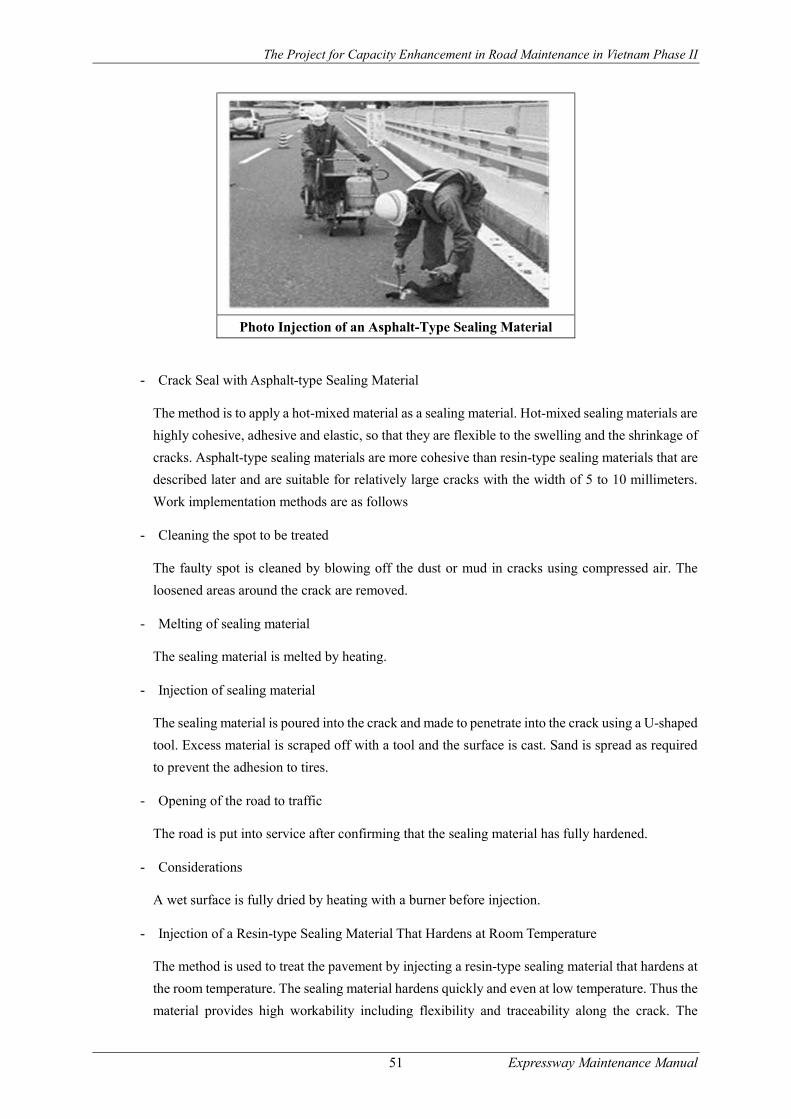
The Project for Capacity Enhancement in Road Maintenance in Vietnam Phase II
51 Expressway Maintenance Manual
Photo Injection of an Asphalt-Type Sealing Material
- Crack Seal with Asphalt-type Sealing Material
The method is to apply a hot-mixed material as a sealing material. Hot-mixed sealing materials are
highly cohesive, adhesive and elastic, so that they are flexible to the swelling and the shrinkage of
cracks. Asphalt-type sealing materials are more cohesive than resin-type sealing materials that are
described later and are suitable for relatively large cracks with the width of 5 to 10 millimeters.
Work implementation methods are as follows
- Cleaning the spot to be treated
The faulty spot is cleaned by blowing off the dust or mud in cracks using compressed air. The
loosened areas around the crack are removed.
- Melting of sealing material
The sealing material is melted by heating.
- Injection of sealing material
The sealing material is poured into the crack and made to penetrate into the crack using a U-shaped
tool. Excess material is scraped off with a tool and the surface is cast. Sand is spread as required
to prevent the adhesion to tires.
- Opening of the road to traffic
The road is put into service after confirming that the sealing material has fully hardened.
- Considerations
A wet surface is fully dried by heating with a burner before injection.
- Injection of a Resin-type Sealing Material That Hardens at Room Temperature
The method is used to treat the pavement by injecting a resin-type sealing material that hardens at
the room temperature. The sealing material hardens quickly and even at low temperature. Thus the
material provides high workability including flexibility and traceability along the crack. The

The Project for Capacity Enhancement in Road Maintenance in Vietnam Phase II
52 Expressway Maintenance Manual
method is therefore applicable to narrow cracks of 5 mm or less.
- Method of patching
The method similar to that for asphalt-type sealing materials is used. No preparation of a sealing
material is, however, required.
- Considerations
When the sealing material penetrates and cause settlement, additional volume of material is
injected again according to the degree of settlement. Resin-type sealing materials are generally
more costly than the asphalt type. They should be used within the designated working life. A wet
surface should completely be dried by heating with a burner or other device before injection.
(2) Pothole Patching & Bump Repair
Pothole patching is to temporarily fill potholes, bumps, local cracks and depressions with asphalt
mixtures. The objective is to control the deterioration of load bearing capacity due to water infiltration
and to improve vehicle riding quality. A simple method is to embed asphalt mixtures or other materials
directly into the damage without applying any pre-treatment (Figure 6.3-3). In another method,
damage areas are cut out and backfilled with asphalt mixtures. The former is applied to the case where
urgency is required. Patching is applied either by hot mixing or by colt mixing.
Figure 6.3-3 Flow of Patching Steps
- Patching by Hot Mix
Patching by hot mixing is fitted to the pavement repair of roads that carry heavy large vehicle
traffic because it provides excellent adhesive strength with existing pavement and high durability
and stability. For the hot asphalt mixtures used by the method, materials similar to those used on
the existing pavement should basically be adopted.
- Preparatory work
Preparations
Transporting and
spreading of mixtures
Compaction by
rolling
Curing

The Project for Capacity Enhancement in Road Maintenance in Vietnam Phase II
53 Expressway Maintenance Manual
Damaged and faulty sections are removed using a concrete cutter and their shape is trimmed. When
repairing small areas such as potholes, no cutting is required. Then, dust and mud in or around the
cut face are removed. Then, a tack coat is laid on the bottom and side surfaces. The excess tack
coat staying in depressions are wiped off with a cloth or by other means.
- Transport and spreading of mixtures
Only a small amount of mixture is generally used. The mixture is covered with membranes during
the transport to prevent temperature drop. The mixture is spread so that the finished level may be
approximately one centimeter higher than the road surface surrounding the faulty spot, taking into
account of settlement after the commencement of service.
- Compaction by rolling
Small road rollers or plate compactors are used for compaction.
- Curing
The surface is cured until it becomes possible to touch with a hand.
- Matters to be taken care of
In the above patch work, the point to be repaired needs to be cleaned and a wet surface needs to
be completely dried. The work should be carried out quickly to obtain the designated compaction
temperature. Heating by burners should be minimized even where necessary.
- Patching by Cold Mix
The method of patching by cold mixing can be implemented at the room temperature. It is easy to
implement and is therefore adopted in emergency. The method is inferior to the hot mixing method
in initial stability and durability, and moreover, it needs the period of curing.
- Preparatory work
Similar pretreatment is done to that in the method by hot mixing.
- Spreading of mixture
Aggregate mixture is wrapped in bags. The mixture is spread so that the finished level may be
approximately one centimeter higher than the road surface surrounding the faulty spot, counting
the magnitude of settlement after the commencement of service.
- Compaction by rolling
Small road rollers or plate compactors are used for compaction.
- Curing
The road should not be put into service until the moisture and solvent of the bituminous material
vaporize.

The Project for Capacity Enhancement in Road Maintenance in Vietnam Phase II
54 Expressway Maintenance Manual
- Considerations
The method is temporarily applicable on roads that carry heavy traffic of large vehicles if urgency
is demanding.
(3) Surface Treatment
Surface treatment is the method to set a thin layer less than 3 cm on the existing pavement surface.
There are some alternative methods available, depending upon material and work types. Surface
treatment has been implemented to cope with pavement deterioration, cracks and pavement wear for
the purpose of preventive road maintenance. Surface treatment is expected to improve water-blocking
performance and skid resistance, thereby to restore and to reinforce existing pavement functions.
When the surface treatment is applied to the light damage as a preventive repair, it is expected to
enhance pavement life. There are several materials such as emulsion, asphalt mixture and resins. It is
necessary to select appropriate materials, taking account of pavement conditions, traffic volume, etc.
- Fog seal
Fog seal is the repair method to restore pavement functions by spraying asphalt emulsion diluted
by 1 to 3 times with water (0.5 –0.9 liters per square meters) and filling into the pavement cracks.
Asphalt emulsion, MK- 2 or 3, has been often used. Sometimes it is used to settle aggregates or
dust after other treatments are done. It is effective to apply this technology to low traffic roads. It
is possible to open traffic in 1 to 2 hours after the repair work. In the case of hastening the opening
of traffic, it is good to spray sand on the sprayed emulsion.
- Chip seal
Chip seal is applied only to the asphalt pavement which finishes aggregate into a single or multiple
layers using emulsion. The former is called a seal coat and the latter an armor coat. Seal coat is to
formulate one layer of emulsion and aggregates, and armor coast is to formulate more than two
layers on the pavement surface. The purposes of this method are as follows.
To fill up small crack and to enhance water resistance and durability with high water tightness
To prevent aging of the existing pavement
To restore pavement surface
To improve wearing resistance
- Slurry seal
This method is to mix fine aggregate, filler, asphalt emulsion and water together and to put them
thin over the asphalt pavement or on the concrete pavement (3 to 10 millimeters). Requirement of
asphalt emulsion to the weight of filler and fine aggregate is 13 to 30%, and of water 10 to 15% in
general. Slurry seal shall be implemented in the field in the warm climate and should not be
implemented in the temperature of less than 15 degrees or in the cloudy days with high humidity.
- Micro surfacing

The Project for Capacity Enhancement in Road Maintenance in Vietnam Phase II
55 Expressway Maintenance Manual
Micro surfacing is a kind of slurry seal which produce slurry cold mixtures of carefully selected
aggregate, modified bitumen with rapid rigidity, asphalt emulsion, cement, water and
decomposition regulator and spread them thin over existing pavement by using micro-surfacing
paving machine. This method does not need heating in producing mixture and in construction in
the field, and is fairly energy saving, thereby contribute to reduce carbon dioxide emission. Micro
surfacing has been applied to the asphalt and the concrete pavement to restore pavement functions
from aging and rut damage, to improve pavement texture and to conduct preventive maintenance.
Construction of micro-surfacing is in general done with one layer whose thickness is from 3 to 10
millimeters placed on the asphalt and the concrete pavement surface. However, when applied to
the pavement whose rut is heavy (15 to 20 millimeters in depth), two layer repair is sometimes
applied.
Special equipment is used to produce mixture and to place pavement, which has all necessary
functions in the equipment such as those for saving materials, mixing materials and paving
materials on the pavement surface, thereby make it possible to conduct continuous work while
moving forward (Figure 6.3-4).
Figure 6.3-4 Micro-surfacing Pavement Machine
- Carpet coat
This method is applied to normal asphalt and concrete pavement. Hot asphalt mix is laid on the
pavement surface and compacted in 1.5 – 2.5cm thick layer. This method features early open to
traffic after the repair work. Compared with other overlay methods, this has thinner layer than it.
Carper coat is a hot mixture produced by mixing crusher-run, screening, sand, filler and carbon
binder. Maximum grain size of aggregate should be less than half of the pavement thickness and
5 mm aggregate is in principle used.
(Source) Guidebook 2013 for Pavement Maintenance and
Repair in Japan, Japan Road Association
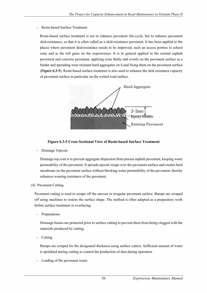
The Project for Capacity Enhancement in Road Maintenance in Vietnam Phase II
56 Expressway Maintenance Manual
- Resin-based Surface Treatment
Resin-based surface treatment is not to enhance pavement life-cycle, but to enhance pavement
skid-resistance, so that it is often called as a skid-resistance pavement. It has been applied to the
places where pavement skid-resistance needs to be improved, such an access portion to school
zone and to the toll gates on the expressways. It is in general applied to the normal asphalt
pavement and concrete pavement, applying resin thinly and evenly on the pavement surface as a
binder and spreading wear resistant hard aggregates on it and fixing them on the pavement surface
(Figure 6.3-5). Resin-based surface treatment is also used to enhance the skid resistance capacity
of pavement surface in particular on the wetted road surface.
Figure 6.3-5 Cross Sectional View of Resin-based Surface Treatment
- Drainage Topcoat
Drainage top coat is to prevent aggregate dispersion from porous asphalt pavement, keeping water
permeability of the pavement. It spreads special resign over the pavement surface and creates hard
membrane on the pavement surface without blocking water permeability of the pavement, thereby
enhances wearing resistance of the pavement.
(4) Pavement Cutting
Pavement cutting is used to scrape off the uneven or irregular pavement surface. Bumps are scraped
off using machines to restore the surface shape. The method is often adopted as a preparatory work
before surface treatment or overlaying.
- Preparations
Drainage basins are protected prior to surface cutting to prevent them from being clogged with the
materials produced by cutting.
- Cutting
Bumps are scraped for the designated thickness using surface cutters. Sufficient amount of water
is sprinkled during cutting to control the production of dust during operation.
- Loading of the pavement waste
Hard Aggregate
Epoxy binder
Existing Pavement

The Project for Capacity Enhancement in Road Maintenance in Vietnam Phase II
57 Expressway Maintenance Manual
The pavement waste produced by cutting is loaded on dump trucks using loading machines for
transport to designated sites.
- Cleaning
Road sweepers are used to completely clean the surface while sprinkling water to control the
production of dust.
- Considerations
The method is a temporary measure. On the surface where rutting due to the flow of asphalt or
corrugations cause problems, therefore, irregularities are likely to recur early. The irregularities
that developed in a short time in particular are highly likely to recur.
(5) Linear Replacement
In linear replacement, the pavement is replaced along linear cracking. The method is generally applied
only to asphalt mixture layers including the layers stabilized with bituminous materials.
- Linear cutting of pavement
The faulty sections with linear cracks are cut off. For cutting, a cutter is placed along the crack and
the section is scraped off with a breaker or backhoe.
- Tack coat
The cut spot is cleaned with a compressor and cured by evenly spreading emulsified asphalt using
an engine sprayer. Then, the cut surface in the existing asphalt mixture layer is also fully coated
with emulsified asphalt using a brush.
- Laying of a mixture
A hot mixture is manually spread and compacted using a small vibratory roller or tire roller. Joints
should be carefully compacted because the joints are likely to be compacted poorly, resulting in
weak points.
- Curing
The pavement is cured until the surface temperature drops below 50 C before opening the road to
traffic.
Implementation of Periodic Repair
In the case where a pavement has been greatly damaged, a fundamental treatment shall be applied to
the pavement through repair work. Asphalt pavement repair methods include overlaying, cutting and
overlaying, replacement and local replacement. All are more costly than maintenance. The damage to
pavements is caused by various factors. The repair method should therefore be adopted based on the
materials including various survey results. The planar scope of the damage, timing of repair, and traffic
and roadside conditions need to be examined carefully.
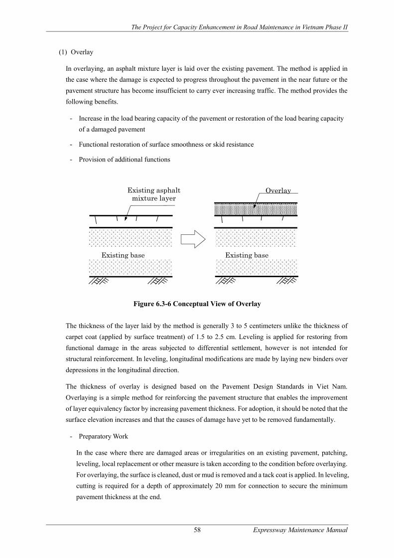
The Project for Capacity Enhancement in Road Maintenance in Vietnam Phase II
58 Expressway Maintenance Manual
(1) Overlay
In overlaying, an asphalt mixture layer is laid over the existing pavement. The method is applied in
the case where the damage is expected to progress throughout the pavement in the near future or the
pavement structure has become insufficient to carry ever increasing traffic. The method provides the
following benefits.
- Increase in the load bearing capacity of the pavement or restoration of the load bearing capacity
of a damaged pavement
- Functional restoration of surface smoothness or skid resistance
- Provision of additional functions
Figure 6.3-6 Conceptual View of Overlay
The thickness of the layer laid by the method is generally 3 to 5 centimeters unlike the thickness of
carpet coat (applied by surface treatment) of 1.5 to 2.5 cm. Leveling is applied for restoring from
functional damage in the areas subjected to differential settlement, however is not intended for
structural reinforcement. In leveling, longitudinal modifications are made by laying new binders over
depressions in the longitudinal direction.
The thickness of overlay is designed based on the Pavement Design Standards in Viet Nam.
Overlaying is a simple method for reinforcing the pavement structure that enables the improvement
of layer equivalency factor by increasing pavement thickness. For adoption, it should be noted that the
surface elevation increases and that the causes of damage have yet to be removed fundamentally.
- Preparatory Work
In the case where there are damaged areas or irregularities on an existing pavement, patching,
leveling, local replacement or other measure is taken according to the condition before overlaying.
For overlaying, the surface is cleaned, dust or mud is removed and a tack coat is applied. In leveling,
cutting is required for a depth of approximately 20 mm for connection to secure the minimum
pavement thickness at the end.
OverlayExisting asphalt mixture layer
Existing base Existing base
The Project for Capacity Enhancement in Road Maintenance in Vietnam Phase II
59 Expressway Maintenance Manual
- Tack coat
A designated amount of emulsified asphalt is evenly spread using distributors or other devices. At
the end point of cutting, spreading is done manually or using simple pump spreaders. Care should
be exercised to prevent emulsified asphalt from staying on the existing surface.
- Spreading of a mixture
The mixture is usually spread using asphalt finishers, or manually in areas where no finishers can
be used. The mixture is spread so as to achieve the designated thickness after compaction. If it
starts raining while spreading the mixture, spreading should be suspended. The mixture that has
been spread should be compacted quickly and finished.
- Compaction
The mixture that has been spread is compacted so as to obtain the designated density. Compaction
generally starts with joint compaction and proceeds to the primary and secondary compaction and
ends with finishing. The primary compaction is done by two-time trips, or a back-and-forth trip,
of a 10- to 12-ton roller. Compaction is carried out at the highest temperature possible as long as
no hair crack occurs. The compaction temperature is generally 110 to 140 C. In order to prevent
the mixture from adhering to the roller, a small amount of water may be sprayed thinly over the
surface using an atomizer. For the secondary compaction, eight- to 20-ton tire rollers or six- to 10-
ton vibratory rollers are generally used. Compacting the mixture by tire rollers improves the
interlocking of aggregates owing to the force of compaction as under traffic loading, and is
expected to achieve a uniform density in the depth direction. Using vibratory rollers with
appropriate loading, frequency of vibration and amplitude produces the designated degree of
compaction in smaller numbers of times of rolling than using tire rollers. The secondary
compaction is generally carried out at 70 to 90 C. Finishing is done to correct irregularities or
eliminate roller marks. Tire rollers or road rollers should travel back and forth once. In the case
where vibratory rollers are used for secondary compaction, tire rollers should preferably be
employed for finishing. No roller should stay for a long time on the just-finished pavement.
- Curing
The pavement is cured until the surface temperature drops below 50 C before opening the road to
traffic.
- Considerations
Overlaying is suitable for controlling relatively moderate cracks that occur on the pavement
surface. In the case of the occurrence of numerous cracks that are likely to reach the base course
or sub grade, replacement is preferable. After the completion of the leveling work, it is necessary
to secure the adequate height of safety fence and the drainage capacity.
(2) Cutting and Overlaying
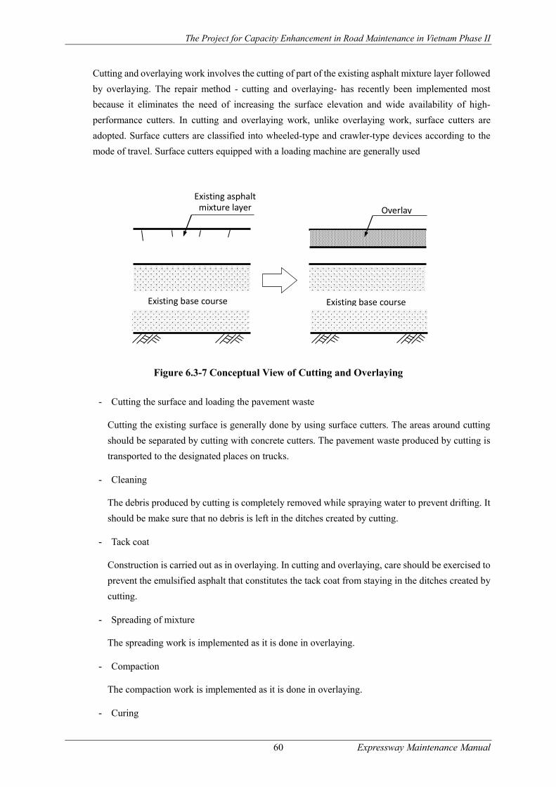
The Project for Capacity Enhancement in Road Maintenance in Vietnam Phase II
60 Expressway Maintenance Manual
Cutting and overlaying work involves the cutting of part of the existing asphalt mixture layer followed
by overlaying. The repair method - cutting and overlaying- has recently been implemented most
because it eliminates the need of increasing the surface elevation and wide availability of high-
performance cutters. In cutting and overlaying work, unlike overlaying work, surface cutters are
adopted. Surface cutters are classified into wheeled-type and crawler-type devices according to the
mode of travel. Surface cutters equipped with a loading machine are generally used
Figure 6.3-7 Conceptual View of Cutting and Overlaying
- Cutting the surface and loading the pavement waste
Cutting the existing surface is generally done by using surface cutters. The areas around cutting
should be separated by cutting with concrete cutters. The pavement waste produced by cutting is
transported to the designated places on trucks.
- Cleaning
The debris produced by cutting is completely removed while spraying water to prevent drifting. It
should be make sure that no debris is left in the ditches created by cutting.
- Tack coat
Construction is carried out as in overlaying. In cutting and overlaying, care should be exercised to
prevent the emulsified asphalt that constitutes the tack coat from staying in the ditches created by
cutting.
- Spreading of mixture
The spreading work is implemented as it is done in overlaying.
- Compaction
The compaction work is implemented as it is done in overlaying.
- Curing
Existing base course Existing base course
Overlay Existing asphalt
mixture layer

The Project for Capacity Enhancement in Road Maintenance in Vietnam Phase II
61 Expressway Maintenance Manual
The curing work is carried out as in overlaying. Spreading Primary compaction by a road roller
Secondary compaction by a tire roller
(3) Replacement
In replacement, the existing pavement is partly or fully removed and a new pavement is constructed.
The method is implemented in cases where the pavement has been seriously damaged and the damage
has reached the sub grade or base course, or where the surface has a limited elevation. The types of
damage to which the method is applied include the deterioration of the load bearing capacity of sub
grade or base course and the rutting and cracking ascribable to settlement. The pavement is replaced
from the surface to the layer with considerably deteriorated strength. In the case where the base course
has suffered from the deterioration of load bearing capacity, the pavement is replaced using excellent
materials or is stabilized.
Figure 6.3-8 Conceptual View of Replacement
- Preparations
The points of replacement (e.g. start and end points and longitudinal joints) are specified explicitly.
- Demolition of the existing pavement and transport of the pavement waste
The edge of the area to be replaced is cut to the designated depth by a cutter. The existing asphalt
mixture is pulled up with a cutter or breaker and fragmented. The existing asphalt mixture that has
been fragmented with a shovel loader or backhoe is loaded on dump trucks and transported to
designated places. The sub grade is to be treated carefully so as to finish it as smooth as possible.
- Construction of a sub-base (granular sub-base)
Irregularities on the cut surface are corrected using a bulldozer or grader while confirming the
elevation of finished sub grade. The base course materials delivered by dump trucks are spread by
bulldozers. Compaction is done using a road roller or a tire roller. The edge is corrected manually
and carefully compacted with a rammer or other equipment.
- Prime coat

The Project for Capacity Enhancement in Road Maintenance in Vietnam Phase II
62 Expressway Maintenance Manual
A designated amount of emulsified asphalt is spread evenly with an engine sprayer and cured.
When spreading, protection is provided using concrete panels or other materials to prevent the
emulsion from drifting.
- Construction of a base course (base stabilized with bitumen)
Construction is carried out as in overlaying.
- Tack coat work
Emulsified asphalt is evenly spread with a distributor and is cured. When spraying the emulsion,
protection is provided using concrete panels or other materials to prevent the emulsion from
drifting.
- Construction of wearing course and binder course
Construction is carried out by the same manner as is done in overlaying. When the binder course
temperature drops to approximately 50 C, the tack coat works and the wearing course work are
undertaken. The work is done as in overlaying. When the wearing course surface temperature
drops to approximately 50 C, the pavement is opened to traffic. Then, pavement markings are
placed using dedicated machines by a separate work.
(4) Local Replacement
Local replacement of the wearing course, binder course or sub-base is one of the measures employed
when the existing pavement is greatly damaged locally by cracking or other factors and suffered from
structural damage as revealed by the preliminary survey... The method may sometimes be
implemented in areas that suffered serious local damage before overlaying or “cutting and overlaying”
is implemented.
- Preparatory work
The points of replacement (e.g. start and end points and longitudinal joints) are to be marked.
- Demolition of existing pavement and transport of the pavement waste
The edge of the area to be replaced is cut to the designated depth by a cutter. The existing asphalt
mixture is pulled up with a small cutter or breaker and fragmented. The existing asphalt mixture
that has been fragmented with a backhoe or shovel loader is loaded on dump trucks and transported
to designated places.
- Construction of a sub-base
Irregularities on the cut surface are corrected manually or using a backhoe while confirming the
elevation of finished sub grade. The base course materials that are delivered by dump trucks are
spread manually or using a backhoe. Compaction is done carefully with a rammer or plate
compactor.
- Prime coat

The Project for Capacity Enhancement in Road Maintenance in Vietnam Phase II
63 Expressway Maintenance Manual
A designated amount of emulsified asphalt is spread evenly with an engine sprayer and is cured.
When spreading, protection is provided using concrete panels or other materials to prevent the
emulsion from drifting.
- Construction of a base course (base course stabilized with bitumen)
The mixture is spread manually and compaction is done carefully using a rammer or plate
compactor to construct the upper base.
- Tack coat work
A designated amount of emulsified asphalt is spread evenly with an engine sprayer and cured.
When spreading, protection is provided using concrete panels or other materials to prevent the
emulsion from drifting.
- Construction of wearing course and binder course
The binder course mixture is manually spread, and carefully compacted using a rammer or plate
compactor to construct the binder course. Then, a tack coat is applied. The surface layer (wearing
course) mixture is manually spread, and carefully compacted using a rammer or plate compactor
to construct the surface layer. Pavement markings are placed with a line marker. When the
pavement surface temperature drops to approximately 50 C, the pavement is opened to traffic.
- Considerations
Local replacement is prone to cause settlement after the road is opened to traffic. Careful
compaction is required in construction. Settlement is likely to occur at the edge in particular. It is
therefore desirable to place the finished surface of the surface layer approximately 0.5 cm higher
than the existing pavement. When two or more layers are constructed, the overlapping of joints
should be avoided and the upper layers should be removed with a wider margin to facilitate
compaction (Error! Reference source not found.).
Figure 6.3-9 Excavation in local replacement
Asphalt layer
A 15-cm gap is
Excavation Base
Sub

The Project for Capacity Enhancement in Road Maintenance in Vietnam Phase II
64 Expressway Maintenance Manual
Bridge Pavement Maintenance Management
Introduction
Surface of elevated road or viaduct (hereinafter called bridge pavement surface) is the surface of bridge
road and viaduct which have floor slab (concrete floor slab, steel floor). Construction of bridge surface
is implemented with the purpose of heavy load resistance, floor protection and high riding quality.
If the surface condition becomes bad, it shall affect traffic and upper structure of the bridge with the
increase of vibration and impact on the bridge floor slab, water penetration and so on. In fact, there
are a lot of factors influencing on the bridge pavement surface, such as small bridge width resulting to
more critical wheel rutting; sharp horizontal curves due to limited space way near the bridge resulting
high shear stress from wheel loading; limited overlay due to bridge structure. Therefore, it is required
to inspect and maintain to detect incident, find out causes, and settle appropriately.
Typical Defects Observed
In order to repair and improve the bridge surface, it is required to understand failure of the bridge
surface clearly. Reasons for bridge surface failure shall be very different with road surface because
structures under the surface are made of rigid and impermeable materials. Main failures and the causes
are presented in Table 6.4-1.
Table 6.4-1 Classification of the bridge pavement surface failures and the causes
Classification Main causes Main failure related to surface status
Partial crack Hair cracks Quality of compound is not good. Construction temperature is not suitable.
Roughness Asperity near expansion joints
Deformation and abrasion is due to difference in strength of pavement surface materials and expansion joints, and unsteady compound.
Deformation Rutting
Heavy traffic, low speed traffic or stopping traffic, unsteady surface materials, fixed wheel loading, low quality pavement surface
Roughness in longitudinal direction, Corrugation, Depression,
Vibration due to dynamic loading from vehicle on the bridge surface, heavy traffic, unsteady mixtures, floor roughness, too much and irregular quantity of tack coat.
Flushing Too much asphalt in mix compound; unsuitable asphalt (soft asphalt); too much and/or irregular quantity of tack coat.
Abrasion Raveling, Polishing, Peeling
Insufficient compression, lack of asphalt, too hot mixtures resulting to aged asphalt, soft aggregates.
Broken and surface materials losing
Pot hole Stripping Aging
Low quality mixtures, insufficient compression, water absorption, bolts of steel slab.
Other Scratch Uplift
Objects fallen from the vehicles, traffic accidents. Thick mixtures, swollen air under the surface, volatile of tack coat and stream evaporation of concrete slabs.
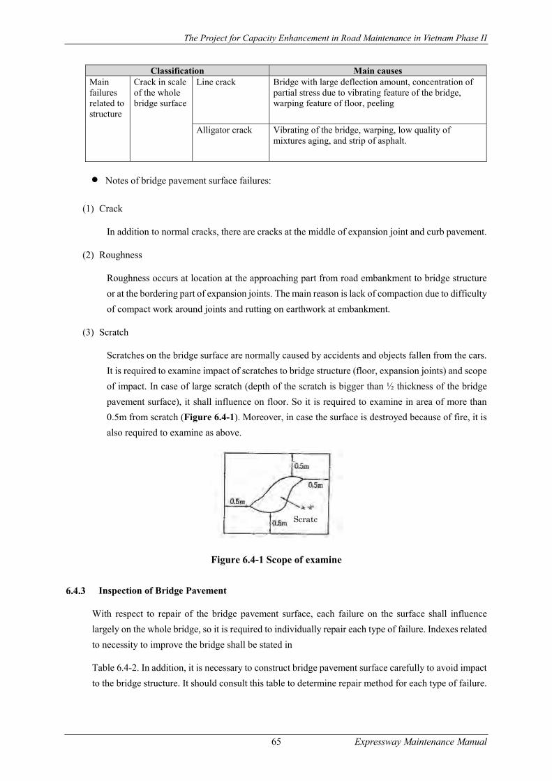
The Project for Capacity Enhancement in Road Maintenance in Vietnam Phase II
65 Expressway Maintenance Manual
Classification Main causes Main failures related to structure
Crack in scale of the whole bridge surface
Line crack Bridge with large deflection amount, concentration of partial stress due to vibrating feature of the bridge, warping feature of floor, peeling
Alligator crack Vibrating of the bridge, warping, low quality of mixtures aging, and strip of asphalt.
Notes of bridge pavement surface failures:
(1) Crack
In addition to normal cracks, there are cracks at the middle of expansion joint and curb pavement.
(2) Roughness
Roughness occurs at location at the approaching part from road embankment to bridge structure
or at the bordering part of expansion joints. The main reason is lack of compaction due to difficulty
of compact work around joints and rutting on earthwork at embankment.
(3) Scratch
Scratches on the bridge surface are normally caused by accidents and objects fallen from the cars.
It is required to examine impact of scratches to bridge structure (floor, expansion joints) and scope
of impact. In case of large scratch (depth of the scratch is bigger than ½ thickness of the bridge
pavement surface), it shall influence on floor. So it is required to examine in area of more than
0.5m from scratch (Figure 6.4-1). Moreover, in case the surface is destroyed because of fire, it is
also required to examine as above.
Figure 6.4-1 Scope of examine
Inspection of Bridge Pavement
With respect to repair of the bridge pavement surface, each failure on the surface shall influence
largely on the whole bridge, so it is required to individually repair each type of failure. Indexes related
to necessity to improve the bridge shall be stated in
Table 6.4-2. In addition, it is necessary to construct bridge pavement surface carefully to avoid impact
to the bridge structure. It should consult this table to determine repair method for each type of failure.
Scratc

The Project for Capacity Enhancement in Road Maintenance in Vietnam Phase II
66 Expressway Maintenance Manual
Table 6.4-2 Indexes related to necessity to repair and improve the bridge
Items
Type of road
Rutting (mm)
Roughness (mm)
Skid resistance coefficient
Crack, space between cracks Diameter of pot hole (cm) Rate (%) Width (mm)
Road for cars 15 10 0.25 20 3 10
Normal road with high traffic 2030 1520 0.25 20 3 1020
Normal road low traffic 3035 2030 - 20 3 20
Note 1: In item of roughness, positions near expansion joint are also included.
Some types of failure (such as crack, pot hole) are caused by bridge structure, so it is required to pay
attention to evaluation work.
Planning of Maintenance and Repair Work
Determination of construction, repair and improvement method should be implemented after
analyzing, studying generally methods of repair and maintenance for each type of failure as stated in
Table 5.9.3 and based on experience.
In case of repair pavement surface on the bridge, some failures are caused by structure, so the repairs
might influence on the whole bridge structure if they are neglected. It is required to examine each type
of failure and repair basing on examination result regardless of failure dimension.
Implementation of Maintenance and Repair
Repair method of the bridge surface is mostly like pavement. In addition, there are some notes during
repairing for bridge pavement:
First-aid repair
Patching
When removing damage part, it is necessary to pay attention not to scratch floor. In addition, it is
required to examine the floor status and find out reasons for failures if any.
Spreading crusher-run and sand
In case the bridge near residential areas, flaking stones that might not be adhered may fly. So it needs
to be care as repairing.
Table 6.4-3 Construction and repair method by damage type
Classification Maintenance/repair work Main failure related to surface status
Partial crack Hair crack, space
Sealing Filling
Roughness Roughness near expansion joint
Patching, reconstruction

The Project for Capacity Enhancement in Road Maintenance in Vietnam Phase II
67 Expressway Maintenance Manual
Classification Maintenance/repair work Deformation Rutting Scarification, replacing, overlay
Roughness in longitudinal direction
Scarification, replacing, overlay
Corrugation Scarification, replacing, overlay Deflection and depression Scarification and carpet-coat method Flush Spreading crusher-run or sand
Abrasion Raveling Carpet coating, patching
Polishing
Carpet coating, surface treatment by resin Carpet coating, patching
Peeling Coating protecting cover, patching Surface materials losing
Pot hole, stripping, aging Patching, reconstruction
Others Scratch Patching Uplift Patching
Main failures related to structure
Allover crack Line-shape crack, Alligator crack
Filling, overlay, reconstruction Carpet coating, overlay, reconstruction
Filling
Because rain might intrude into position between the floor and bridge surface through the crack, it is
required to check carefully and pour joint sealing compound into the crack. At the space between the
bridge surface and bridge structure, after using cutter to fix width of the space, pouring joint sealing
compound into such positions shall be implemented.
Surface treatment
The purpose of the bridge pavement surface repair is not to increase dead load, so it should not use
overlaying method but can use carpet coating to make thin protecting cover. As implementing carpet
coat, it is required to remove roughness near the joints by following procedure.
Contact by cutting end
After cutting head of old bridge surface contacting with the expansion joint as in the Figure 6.4-2,
carpet coat shall be executed to contact with the expansion joint.
Figure 6.4-2 Contact by cutting end at head of expansion joint

The Project for Capacity Enhancement in Road Maintenance in Vietnam Phase II
68 Expressway Maintenance Manual
Figure 6.4-3 Lift-up of Expansion Join
List of materials is as follows: Long bolt, Lock screw, Screw Long bolt, Packing washer, Long screw,
Anchor bar, Washer, Anchor bolt
Lifting of the expansion joint shall be implemented as Error! Reference source not found. after putting
steel, rubber or resin sheet in suitable thickness with coating cover under the expansion joint. In case
of lifting the expansion joint, it needs to replace short bolt by long bolt, then put washer (steel, rubber
or plastic washer). If it is lowered, reverse process is done.
Repair Method
Normally, the repair method is to implement overlay after cutting the bridge surface with appropriate
thickness. It is possible to implement like method of asphalt pavement. However, it is required to pay
attention to followings:
Particular Note for Cutting
On the concrete deck, thickness of the surface is not consistent because of irregular floor, so it is
required not to cut floor when cutting the old surface.
On the steel floor, it might have screw head, bolt head; therefore, it is required to check carefully and
draw this position on the old surface before cutting and this work requires man power.
Cut carefully and pay attention to cut so that concrete floor, steel floor, expansion joint and bridge
connecting part, are not destroyed and it needs to construct by machine first, then use man power. On
the other hand, it is required to pay attention not to destroy rubber joint by heat.
Paving
In case of the bridge surface, positions surrounding the bridge connecting part and expansion joint
easy to contract and to be lack; therefore, it is required to pay attention to contraction after putting into
service. As finishing the expansion joint, it is better to finish at position a little higher than that of the
expansion joint (around 23mm).
The Project for Capacity Enhancement in Road Maintenance in Vietnam Phase II
69 Expressway Maintenance Manual
Tunnel Pavement Maintenance and Management
With respect to road surface inside the tunnel, because road floor is solid rock in many cases, road
surface shall be designed thinner than that of other roads. In addition, because of irregular level of
road floor due to excavating and irregular thickness of the road base due to laying drainage culverts,
bearing capacity is not identical.
Moreover, after finishing, it is impossible to avoid water leak due to spring water, so it is very difficult
to maintain initial status of the road base. Hence, before repairing or upgrading the road surface inside
the tunnel, it is required to examine method to prevent water leak.
Abnormal state of the road surface which is paved inside the tunnel might cause traffic accidents, so
it is required to pay attention when checking visually by walking. As detecting special incidents, it is
necessary to resolve them immediately and appropriately. When repairing the road surface inside the
tunnel, it is required to use reconstruction method and reconstruction after scarifying to ensure
clearance. In respect to light efficiency and leak resistance, cement concrete pavement is required;
however, asphalt pavement is usually used.
Bridge Maintenance Management
Introduction
Bridge repairing is the process of repairing the damage that is judged to be necessary to repair as a
result of the detailed inspection and investigation.
- Bridge repairing is repairing the damaged parts to improve the durability of the bridge. It is
different from reinforcing to improve the load bearing capacity of the bridge.
- Repairing is carried out in order to improve the durability and to increase the life of the structure
of the bridge, along with avoiding damage propagation.
- If the judge is required to repair, or is likely to cause impaction to the third one, or affect the
road traffic, it is necessary to repair in the shortest time.
However, the load bearing capacity and durability of the bridge is often not reduced dramatically so if
we want to fix in order to improve the load bearing capacity and durability of the bridge, basing on
the actual situation of the bridge, we will select time to carry out the appropriate repairing.
Typical Damages Observed
Common damage
Following are common defects and deteriorations to all type of bridges. These defects/deteriorations
sometimes affect stability and durability of the bridge.

The Project for Capacity Enhancement in Road Maintenance in Vietnam Phase II
70 Expressway Maintenance Manual
Abnormal deflection
Sagging or hogging deflection which is observed due to concrete creep, internal stresses caused by
concrete drying shrinkage and inadequate PC wire stresses. Following is the point to note in carrying
out the inspections.
- Observe the alignment of the lane marking and the handrail/guardrail.
Abnormal noise
Abnormal banging noise or creaking noise which are observed due to damage of the joints or internal
movement of the joints. Following is the point to note in carrying out the inspections.
- Pay attention on noise carefully near the joints.
Abnormal vibration
Abnormal vibration is palpably observable. Following is the point to note in carrying out the
inspections.
- Pay attention on vibration at the span centre area of the bridge.
Abnormal expansion gaps
Expansion gaps between girders, abutments and joints which are too narrow or too wide, which caused
by tilting of the substructures, lack of consideration on the design, and lack of accuracy of structure
dimension at construction stage. Following is the point to note in carrying out the inspections.
+ Measure the expansion gaps when it identified
Settlement
Settlement is observed on bridge structures including sub structures, foundations and their associated
facilities. Uneven settlement observed at joints, which is caused settlement of substructures. Following
is the point to note in carrying out the inspections.
- Conduct visual inspection on the joints, and vertical alignment of the handrail/guardrail.
Movement
Rotation or movement of structures occurs at bridge substructures such as abutments, and piers due to
settlement and tilting of substructures. Following is the point to note in carrying out the inspections.
- Conduct measuring of the joint gaps, plumb survey, and elevation survey.
Scouring
Scouring, which is caused by swift current, exposes structures including footings and foundations of
bridges constructed in a river or the sea. Due to scouring bridge foundations expose above the river
bed and affects stability of the bridges. Following is the point to note in carrying out the inspections.
- Conduct visual inspection of topographic condition of the river bank, river bed around the

The Project for Capacity Enhancement in Road Maintenance in Vietnam Phase II
71 Expressway Maintenance Manual
foundation.
Concrete bridges
A characteristic of concrete structures is that steel members such as reinforcing bar (hereinafter
referred to as “rebar”), and pre-stressing cable (hereinafter referred to as “PC cable”) are embedded in
concrete structures, so that repair works and strengthening of structures will become hard if corrosion
progresses to steel members inside. Also, the quality of concrete construction may have large impact
on the load-bearing capacity of the concrete structures. Environmental conditions around the bridge
also have negative impacts on the progress of concrete deterioration, so that early detection of defects
and deterioration along with understanding their environment would be a key for the better
maintenance of concrete facilities.
The following are typical defects and deterioration often observed during bridge inspection.
Crack
There are various influential factors causing cracks, such as those including drying shrinkage, tensile
stresses, materials, construction methods, environment, designs, external working forces and so forth.
Concrete cracks allow water infiltration into the concrete and have a negative effect on the steel
members in the concrete and affect life-length of the concrete structures due to loosing tensile strength
of the structures. In addition, corrosion causes rebar diameter expansion which brings peeling of
concrete cover and causes further corrosion of rebar. The following are the points to note in carrying
out the inspections. To identify concrete crack following inspection method is commonly implemented.
- Conduct short distance visual inspection.
Concrete peeling, creep
Concrete peeling is caused by the swelling of rusted rebar, concrete inner stresses and improper
treatment of construction joints, causing peeling, spalling and the creep of concrete surfaces. Peeling
of concrete causes rebars exposure and develops rebar corrosion and consequently rebars loose its
tensile strength. To identify concrete peeling, creep following inspection method is commonly
implemented.
- Conduct short distance visual inspection, and conduct short distance visual inspection, if
necessary.
Rebar exposure
Rebar exposure caused by the effects of concrete peeling, creep or improper construction methods.
Exposed rebar get rust and develop corrosion easily. To identify rebar exposure following inspection
method is commonly implemented.
- Observe surface of the concrete structure body, and conduct short distance visual inspection, if
necessary.
The Project for Capacity Enhancement in Road Maintenance in Vietnam Phase II
72 Expressway Maintenance Manual
Water leakage and Puddles
Water leakage and puddles occur due to rain water infiltrating through concrete joints, penetrating
cracks, expansion joints and damaged drain systems. Water leakage and puddles cause rebar corrosion.
To identify rebar exposure following inspection method is commonly implemented.
- Observe surface of the concrete structure body together with concrete crack inspection.
Free lime
Free lime is a phenomenon causing the lime component of concrete to flow out of construction joints
or out of penetrated cracks with water infiltrating into the concrete body. To identify free lime
following inspection method is commonly implemented.
- Observe surface of the concrete structure body.
Rusty fluid
Rusting of rebar buried in the concrete progresses and flows out from concrete cracks, showing the
Rusty fluid. To identify rusty fluid following inspection method is commonly implemented.
- Observe surface of the concrete structure body.
Deterioration and Discoloration
Deterioration of concrete, which may degrade concrete performance, is caused by chemical reactions.
Discoloration is a phenomenon changing concrete colour by deterioration.
- Observe surface of the concrete structure body.
Honey comb, Void
Honey combs, voids are caused by mainly poor quality control during construction stage. These defect
cause rebar rusting and corrosion. To identify honey comb and void following inspection method is
commonly implemented
- Observe surface of the concrete structure body.
Chemical attacks
Following are typical chemical attacks;
(1) Penetrated carbon dioxide into concrete changes concrete property from alkali to neutrality and loose
protection function of rebar from rusting.
To identify neutralization depth of the concrete following inspection method is commonly
implemented.
- Conduct phenolphthalein solution test on the collected core/powder of the concrete.
(2) Penetrated chloride particle in the air into concrete causes rebar rusting directly.
The Project for Capacity Enhancement in Road Maintenance in Vietnam Phase II
73 Expressway Maintenance Manual
To identify chloride penetration depth in the concrete following inspection method is commonly
implemented.
- Conduct chloride contents test on the collected core/powder of the concrete.
When alkali reaction aggregate are used as concrete material often crocodile cracks are found on the
surface of concrete structures which are facing high possibility of rebar rusting.
- Conduct alkali reaction test on the collected core of the concrete.
Steel bridges
Following are typical defects and deterioration often observed during steel bridge inspection.
Deterioration of paint
Cracks, swelling and peeling are observed on the bridge paint including corrosion due to their effects.
To identify deterioration of paint following inspection method is commonly implemented.
- Conduct short distance visual inspections which pay attention on corrosion of steel members,
condition of discoloration and chalking, peeling, cracking and swelling of paint film on the steel
members.
Corrosion
Concentrated corrosion is observed on the steel materials or reduction in cross section is observed on
steel materials due to the effects of corrosion. To identify corrosion following inspection method is
commonly implemented.
- Conduct short distance visual inspections with scaffoldings, if necessary.
Looseness and falling of rivets and HTBs
Loosening and falling of rivets, bolt-nuts and HTBs are observed at joints. To identify looseness and
falling of rivets, bolt-nuts and HTBs following inspection method is commonly implemented.
- Conduct short distance visual inspections and hammering check with scaffoldings, if necessary.
Cracks
Steel material fatigue cracks are observed at the places where stress concentration occurs, where there
are changes in steel material cross section and where welding connection area. Also, cracks are
observed, which are caused by over stress due to earthquakes and vehicle collisions or high frequency
of over loaded vehicle passages. To identify cracks on the steel members following inspection method
is commonly implemented.
- Conduct short distance visual inspections with scaffoldings, if necessary.
- In case crack is unclear in the inspection, the following tests shall be carried out to detect cracks;
Penetrant inspection
Magnetic particle examination

The Project for Capacity Enhancement in Road Maintenance in Vietnam Phase II
74 Expressway Maintenance Manual
Ultrasonic examination
Deformation, buckling
Deformation or buckling is observed in the steel materials due to over stress caused by earthquakes
and vehicle collisions or high frequency of over loaded vehicle passages.
- Pay attention on the shape of steel members during visual inspection.
Water leakage, puddles
Water infiltration is observed in the places where it is hard to treat pooled water, such as those
where steel members cross each other or inside steel piers.
Inspection of Bridge
Focus Points of Inspection
Bridge inspection are not only to detect bridge damages promptly which may lead to negative
effect to durability of the bridge, but also to obtain data for strategic planning of maintenance and
repair works of the bridges. The following are the points to be focused on in implementing bridge
inspection.
Concrete superstructure
Girder
The following are the points to be focused on implementing concrete bridge girders inspection.
(1) Girder end support area
Locations where the horizontal force caused by the bearing shoe reaction, earthquakes and changes in
temperature. In this area following cracks observed.
- Vertical cracks on the lower side or both sides of a girder on a support.
- Diagonal cracks on the webs of a girder on a support.
- Horizontal cracks on the webs of a girder.
(2) Intermediate supporting area
Locations where negative bending moment and shear forces to be maximum values. Also, stress
conditions around the locations become complicated due to the concentrated support reaction force
and cracks are prone to emerge.
- Vertical cracks on the upper side of a continuous main girder near support.
(3) Span centre
Locations where bending moments show maximum values and thereby bending cracks are prone to
emerge.
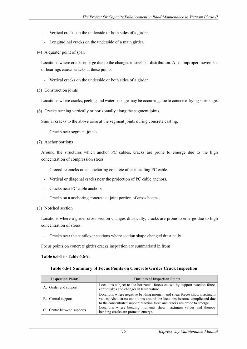
The Project for Capacity Enhancement in Road Maintenance in Vietnam Phase II
75 Expressway Maintenance Manual
- Vertical cracks on the underside or both sides of a girder.
- Longitudinal cracks on the underside of a main girder.
(4) A quarter point of span
Locations where cracks emerge due to the changes in steel bar distribution. Also, improper movement
of bearings causes cracks at these points.
- Vertical cracks on the underside or both sides of a girder.
(5) Construction joints
Locations where cracks, peeling and water leakage may be occurring due to concrete drying shrinkage.
(6) Cracks running vertically or horizontally along the segment joints.
Similar cracks to the above arise at the segment joints during concrete casting.
- Cracks near segment joints.
(7) Anchor portions
Around the structures which anchor PC cables, cracks are prone to emerge due to the high
concentration of compression stress.
- Crocodile cracks on an anchoring concrete after installing PC cable.
- Vertical or diagonal cracks near the projection of PC cable anchors.
- Cracks near PC cable anchors.
- Cracks on a anchoring concrete at joint portion of cross beams
(8) Notched section
Locations where a girder cross section changes drastically, cracks are prone to emerge due to high
concentration of stress.
- Cracks near the cantilever sections where section shape changed drastically.
Focus points on concrete girder cracks inspection are summarised in from
Table 6.6-1 to Table 6.6-9.
Table 6.6-1 Summary of Focus Points on Concrete Girder Crack Inspection
Inspection Points Outlines of Inspection Points
A. Girder end support Locations subject to the horizontal forces caused by support reaction force, earthquakes and changes in temperature
B. Central support Locations where negative bending moment and shear forces show maximum values. Also, stress conditions around the locations become complicated due to the concentrated support reaction force and cracks are prone to emerge.
C. Centre between supports Locations where bending moments show maximum values and thereby bending cracks are prone to emerge.

The Project for Capacity Enhancement in Road Maintenance in Vietnam Phase II
76 Expressway Maintenance Manual
Inspection Points Outlines of Inspection Points
D. A quarter point between supports
Locations where cracks emerge due to the changes in steel bar distribution. Also, improper movement of bearings causes cracks at these points.
E. Concrete joints Locations where cracks, peeling and water leakage may arise due to concrete drying shrinkage
F. Segment joints Similar cracks to the above arise at the segment joints during concrete casting.
G. Anchor portions Around the structures which anchor PC cables, cracks are prone to emerge due to the high concentration of tensile stress.
H. Notched section Locations where a girder cross section changes drastically, cracks are prone to emerge due to high concentration of stress.
Table 6.6-2 Cracks near the Girder End Supports

The Project for Capacity Enhancement in Road Maintenance in Vietnam Phase II
77 Expressway Maintenance Manual
Table 6.6-3 Crack near the Intermediate Support
Table 6.6-4 Crack near the Span Center
Table 6.6-5 Crack near the Quarter Point of the Span
Table 6.6-6 Crack near the Construction Joints

The Project for Capacity Enhancement in Road Maintenance in Vietnam Phase II
78 Expressway Maintenance Manual
Table 6.6-7 Crack near the Segment Joints
Table 6.6-8 Crack near the PC Cable Anchors
Table 6.6-9 Crack near the Notched Section
Concrete deck slab inspection
Table 6.6-10 shows the mechanism of crack progress on the concrete decks.
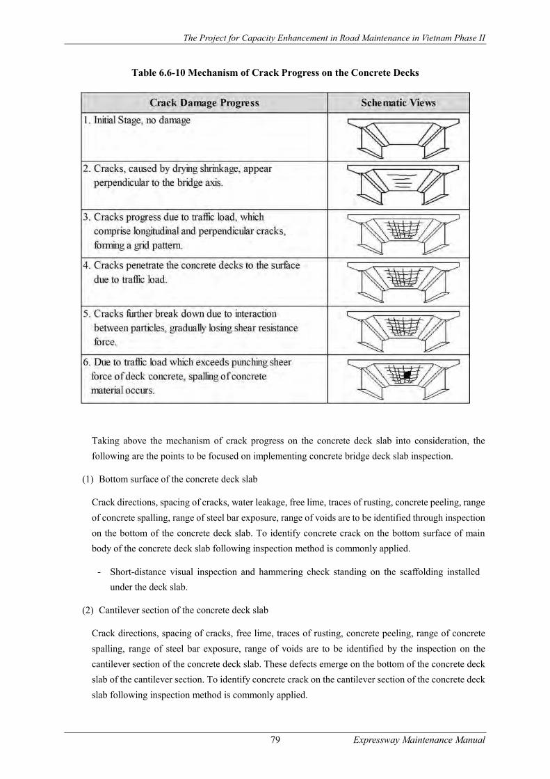
The Project for Capacity Enhancement in Road Maintenance in Vietnam Phase II
79 Expressway Maintenance Manual
Table 6.6-10 Mechanism of Crack Progress on the Concrete Decks
Taking above the mechanism of crack progress on the concrete deck slab into consideration, the
following are the points to be focused on implementing concrete bridge deck slab inspection.
(1) Bottom surface of the concrete deck slab
Crack directions, spacing of cracks, water leakage, free lime, traces of rusting, concrete peeling, range
of concrete spalling, range of steel bar exposure, range of voids are to be identified through inspection
on the bottom of the concrete deck slab. To identify concrete crack on the bottom surface of main
body of the concrete deck slab following inspection method is commonly applied.
- Short-distance visual inspection and hammering check standing on the scaffolding installed
under the deck slab.
(2) Cantilever section of the concrete deck slab
Crack directions, spacing of cracks, free lime, traces of rusting, concrete peeling, range of concrete
spalling, range of steel bar exposure, range of voids are to be identified by the inspection on the
cantilever section of the concrete deck slab. These defects emerge on the bottom of the concrete deck
slab of the cantilever section. To identify concrete crack on the cantilever section of the concrete deck
slab following inspection method is commonly applied.
The Project for Capacity Enhancement in Road Maintenance in Vietnam Phase II
80 Expressway Maintenance Manual
- Short-distance visual inspection and hammering check standing on the scaffolding installed
under the deck slab.
(3) Connection parts with steel girder flange
Free lime, traces of rusting, range of voids, range of concrete peeling and creep are to be identified
through the inspection on the connection section between concrete deck slab and steel girder flange.
To identify concrete crack on the connection parts with the steel girder flange following inspection
method is commonly applied.
- Short-distance visual inspection and hammering check standing on the scaffolding installed
under the deck slab.
(4) Pavement surface
Scale of pavement, potholes and repair works in the past, direction of cracks, spacing of cracks are to
be inspected. Some of these defects on the pavement are caused by defects on the concrete deck slab.
Short distance visual inspection on the road surface is necessary to detect the pavement and concrete
deck slab defects.
Steel bridge inspection
Following are the points to be focused on in implementing steel bridge inspection.
Entire steel bridge surface, members
(1) Paint inspection
Inspection on paint condition of the entire of the bridge including inside of the box girder and the steel
pier is to be carried out to identify paint condition of the bridge. Visual inspection is common
inspection method applied for paint inspection. Following are carried out to identify detailed paint
condition;
- Cut and peel check for identifying deterioration progress of the paint film on the steel members.
- Chalking progress check to confirm deterioration progress of the paint film on the steel members.
- Salt particles density check on the surface of the bridges to confirm corrosion condition of
surrounding environment of the bridges.
- Impedance test to identify the steel member thickness which reduced due to progress of
corrosion.
(2) Corrosion inspection
Inspection method on corrosion including rusting is almost the same with paint inspection. Rust
develops to corrosion, therefore, rust inspection on rust location, rust area and rust level is carried out
as parts of corrosion inspection to prepare maintenance plan including prevention plan for corrosion.
Following area are required much careful inspection due to easy corrosive/restive area.

The Project for Capacity Enhancement in Road Maintenance in Vietnam Phase II
81 Expressway Maintenance Manual
- Water affects area such as under and surrounding area of drainage facilities.
- Bridge members and other facilities concentrated area where always keeping wet condition due
to lack of sun shine and ventilation.
(3) Deformation, buckling inspection
Visual inspection is applicable inspection method for detection of the deformation and buckling of
steel members of the bridges. When passing the bridges all ways pay attention upon deformation and
buckling of the steel members which are visible from the road surface to find out the defects earlier.
Welding points
Cracks on the steel members are observed mainly following welding points:
- Welded portions of sole plates and at changes in cross sections
- Welded portions with stiffeners and gusset plates
- Welded portions on the steel deck plates and stiffness members
- Butt welded portions on the lower flanges
- Welded portions on the base of vertical members on the arch ribs
- Welding portion of the base plates with steel pier
Typical crack appearance patterns are shown in the figures from Figure 6.6-1 toFigure 6.6-7.
Figure 6.6-1 Crack at Welding Portion of the Front End of the Sole Plate
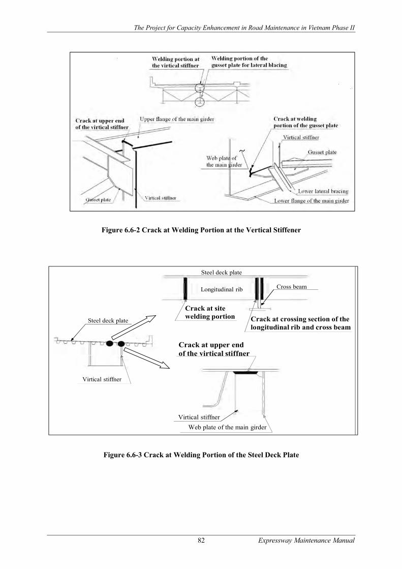
The Project for Capacity Enhancement in Road Maintenance in Vietnam Phase II
82 Expressway Maintenance Manual
Figure 6.6-2 Crack at Welding Portion at the Vertical Stiffener
Figure 6.6-3 Crack at Welding Portion of the Steel Deck Plate
Virtical stiffner
Steel deck plate
Virtical stiffner
Crack at upper endof the virtical stiffner
Web plate of the main girder
Cross beam
Crack at site welding portion
Steel deck plate
Longitudinal rib
Crack at crossing section of the longitudinal rib and cross beam
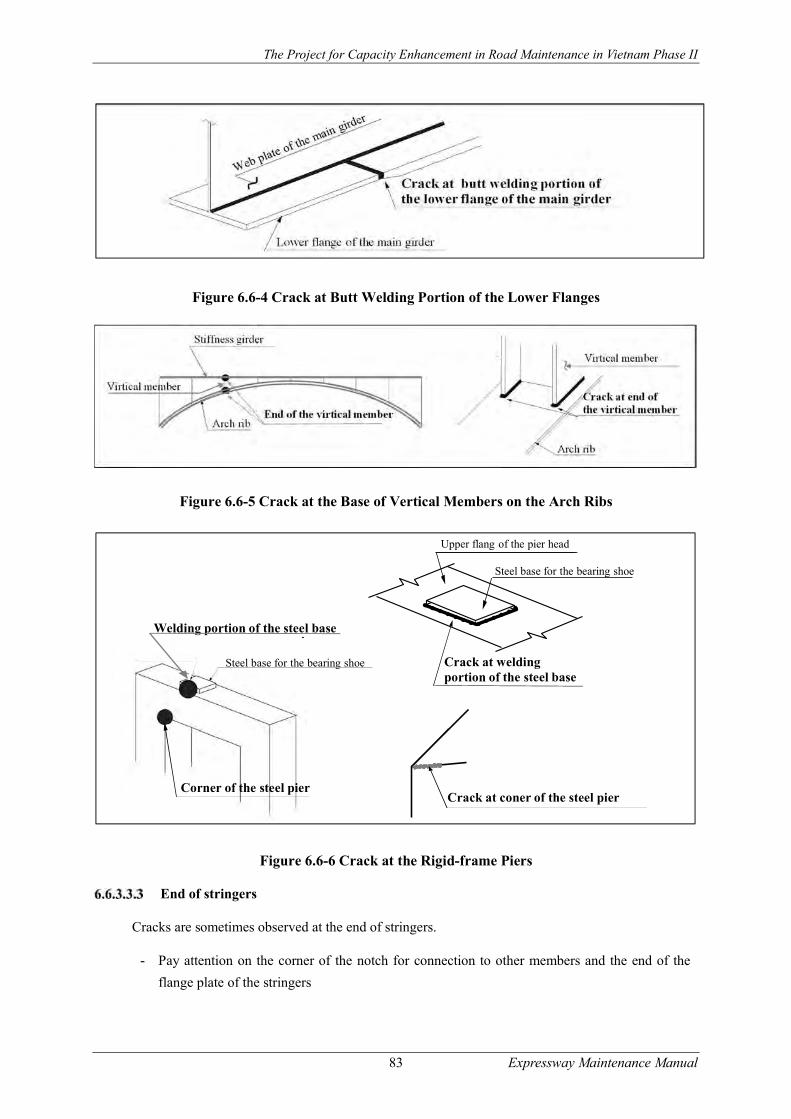
The Project for Capacity Enhancement in Road Maintenance in Vietnam Phase II
83 Expressway Maintenance Manual
Figure 6.6-4 Crack at Butt Welding Portion of the Lower Flanges
Figure 6.6-5 Crack at the Base of Vertical Members on the Arch Ribs
Figure 6.6-6 Crack at the Rigid-frame Piers
End of stringers
Cracks are sometimes observed at the end of stringers.
- Pay attention on the corner of the notch for connection to other members and the end of the
flange plate of the stringers
Crack at welding portion of the steel base
Upper flang of the pier head
Steel base for the bearing shoe
Crack at coner of the steel pier
Welding portion of the steel base
Corner of the steel pier
Steel base for the bearing shoe

The Project for Capacity Enhancement in Road Maintenance in Vietnam Phase II
84 Expressway Maintenance Manual
Figure 6.6-7 Crack from End of the Stringers
Connection and splicing area
Inspection on rivets, bolt-nuts and HTBs are carried out on connecting and splicing portion. In case
loosen nuts found it is necessary re-tightening of the nuts. After inspection and re-tightening of bolt-
nuts and HTBs, marking on nuts is necessary as parts of quality control of works. Visual inspection
and hammering test is effective inspection method.
Drainage facilities
Visual inspection is applicable inspection method for detection of the water leakage and puddles. The
end of the span including expansion joint area, surrounding area of the drainage facilities such as inlet
and outlet of the drainage, basin, and cross points of steel materials (in particular for arch and truss
bridges) are main inspection points for detecting water leakage and puddles.
Substructures and foundations inspection
Following are the points to be focused on in implementing substructures and foundations inspection.
Tilting, settlement, and movement
Visual inspection is applicable for detecting tilting, settlement and movement of the substructures and
foundations. Following are carried out for detect tilting, settlement and movement of the substructures
and foundations as supplemental inspections, when required;
- Measuring gap space and elevation difference of the expansion joints
- Levelling survey of the substructure and foundation
- Incline survey of the stem and parapet wall by a plumb
Scouring
Scouring is caused by swift current of water which brings soil from bottom and surrounding part of
the substructures and foundations constructed in a river or sea including the river edge and shore line,
exposes substructures and foundations of the bridges. Scouring sometimes affects stability of the
bridge seriously. Therefore, it is necessary to confirm scouring condition of the substructures and
foundation of the bridges after heavy rain fall by visual inspection. Following are carried out for detect
scouring of the substructures and foundations as supplemental inspections, when required;
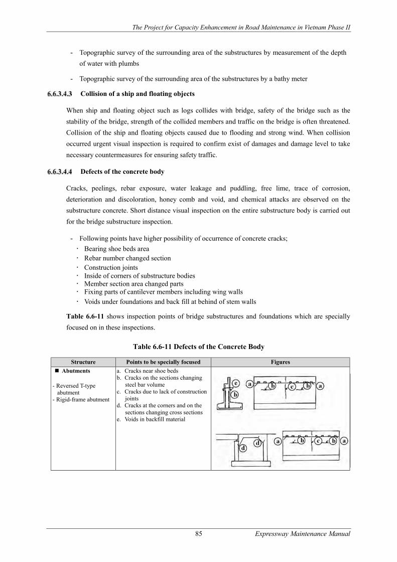
The Project for Capacity Enhancement in Road Maintenance in Vietnam Phase II
85 Expressway Maintenance Manual
- Topographic survey of the surrounding area of the substructures by measurement of the depth
of water with plumbs
- Topographic survey of the surrounding area of the substructures by a bathy meter
Collision of a ship and floating objects
When ship and floating object such as logs collides with bridge, safety of the bridge such as the
stability of the bridge, strength of the collided members and traffic on the bridge is often threatened.
Collision of the ship and floating objects caused due to flooding and strong wind. When collision
occurred urgent visual inspection is required to confirm exist of damages and damage level to take
necessary countermeasures for ensuring safety traffic.
Defects of the concrete body
Cracks, peelings, rebar exposure, water leakage and puddling, free lime, trace of corrosion,
deterioration and discoloration, honey comb and void, and chemical attacks are observed on the
substructure concrete. Short distance visual inspection on the entire substructure body is carried out
for the bridge substructure inspection.
- Following points have higher possibility of occurrence of concrete cracks;
Bearing shoe beds area Rebar number changed section Construction joints Inside of corners of substructure bodies Member section area changed parts Fixing parts of cantilever members including wing walls
Voids under foundations and back fill at behind of stem walls
Table 6.6-11 shows inspection points of bridge substructures and foundations which are specially
focused on in these inspections.
Table 6.6-11 Defects of the Concrete Body
Structure Points to be specially focused Figures
Abutments
- Reversed T-type abutment
- Rigid-frame abutment
a. Cracks near shoe beds b. Cracks on the sections changing
steel bar volume c. Cracks due to lack of construction
joints d. Cracks at the corners and on the
sections changing cross sections e. Voids in backfill material
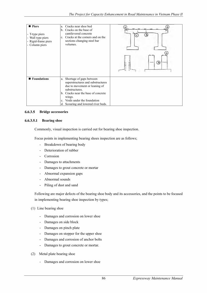
The Project for Capacity Enhancement in Road Maintenance in Vietnam Phase II
86 Expressway Maintenance Manual
Bridge accessories
Bearing shoe
Commonly, visual inspection is carried out for bearing shoe inspection.
Focus points in implementing bearing shoes inspection are as follows;
- Breakdown of bearing body
- Deterioration of rubber
- Corrosion
- Damages to attachments
- Damages to grout concrete or mortar
- Abnormal expansion gaps
- Abnormal sounds
- Piling of dust and sand
Following are major defects of the bearing shoe body and its accessories, and the points to be focused
in implementing bearing shoe inspection by types;
(1) Line bearing shoe
- Damages and corrosion on lower shoe
- Damages on side block
- Damages on pinch plate
- Damages on stopper for the upper shoe
- Damages and corrosion of anchor bolts
- Damages to grout concrete or mortar.
(2) Metal plate bearing shoe
- Damages and corrosion on lower shoe
Piers
- T-type piers - Wall type piers - Rigid-frame piers - Column piers
a. Cracks near shoe bed b. Cracks on the base of
cantilevered concrete c. Cracks at the corners and on the
sections changing steel bar volumes.
Foundations a. Shortage of gaps between superstructures and substructures due to movement or leaning of substructures.
b. Cracks near the base of concrete wings.
c. Voids under the foundation d. Scouring and lowered river beds.

The Project for Capacity Enhancement in Road Maintenance in Vietnam Phase II
87 Expressway Maintenance Manual
- Damages on bearing plates
- Improper contact of side block and breakage of side block bolts
- Damages on the stopper for the upper shoe
- Breakage of set bolts
- Damages and corrosion of anchor bolts
- Damages to grout concrete or mortar.
(3) Multiple roller bearing shoe
- Damages and corrosion on upper shoe, lower shoe and base plate.
- Improper contact of side block and breakage of side block bolts
- Damages to the lower shoe
- Breakage of set bolts
- Damages to pins that impact functioning
- Damages and corrosion of anchor bolts
- Damages to grout concrete or mortar
- Damages on protective cover.
(4) Rubber bearing shoe
- Damages and deterioration on rubber materials
- Displacement and deviation of rubber materials
- Bulging of rubber materials
- Abnormal space between upper shoe and rubber
- Damages on side block and breakage of set bolts
- Damages on the upper shoe stopper
- Breakage of set bolts
- Damages and corrosion of anchor bolts
- Damages on grout concrete or mortar.
Table 6.6-12 shows the focus points of bearing inspection with illustrations.
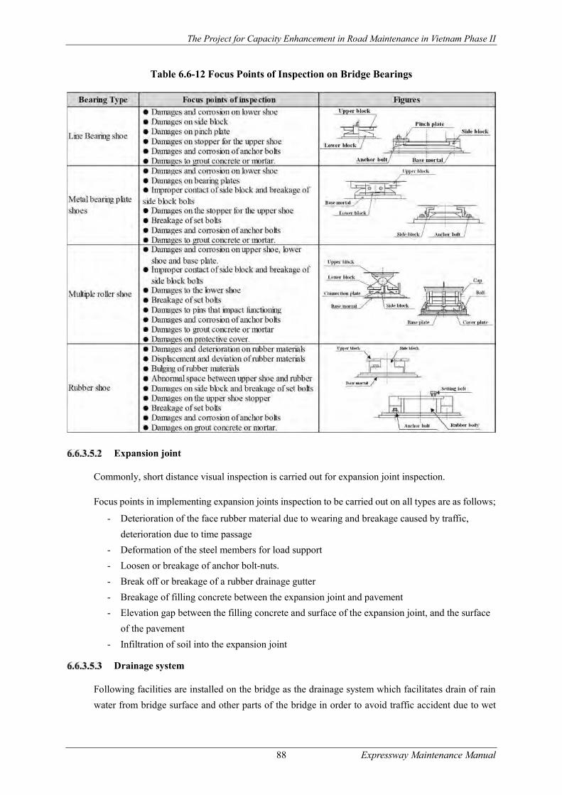
The Project for Capacity Enhancement in Road Maintenance in Vietnam Phase II
88 Expressway Maintenance Manual
Table 6.6-12 Focus Points of Inspection on Bridge Bearings
Expansion joint
Commonly, short distance visual inspection is carried out for expansion joint inspection.
Focus points in implementing expansion joints inspection to be carried out on all types are as follows;
- Deterioration of the face rubber material due to wearing and breakage caused by traffic,
deterioration due to time passage
- Deformation of the steel members for load support
- Loosen or breakage of anchor bolt-nuts.
- Break off or breakage of a rubber drainage gutter
- Breakage of filling concrete between the expansion joint and pavement
- Elevation gap between the filling concrete and surface of the expansion joint, and the surface
of the pavement
- Infiltration of soil into the expansion joint
Drainage system
Following facilities are installed on the bridge as the drainage system which facilitates drain of rain
water from bridge surface and other parts of the bridge in order to avoid traffic accident due to wet
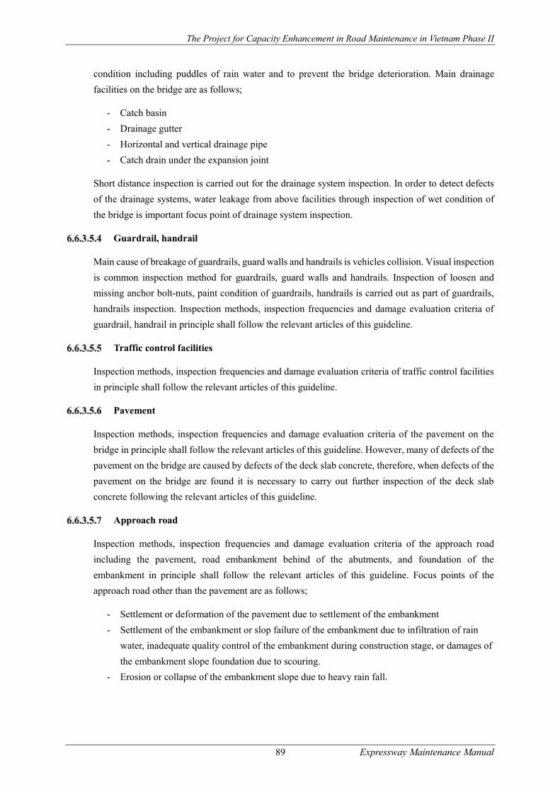
The Project for Capacity Enhancement in Road Maintenance in Vietnam Phase II
89 Expressway Maintenance Manual
condition including puddles of rain water and to prevent the bridge deterioration. Main drainage
facilities on the bridge are as follows;
- Catch basin
- Drainage gutter
- Horizontal and vertical drainage pipe
- Catch drain under the expansion joint
Short distance inspection is carried out for the drainage system inspection. In order to detect defects
of the drainage systems, water leakage from above facilities through inspection of wet condition of
the bridge is important focus point of drainage system inspection.
Guardrail, handrail
Main cause of breakage of guardrails, guard walls and handrails is vehicles collision. Visual inspection
is common inspection method for guardrails, guard walls and handrails. Inspection of loosen and
missing anchor bolt-nuts, paint condition of guardrails, handrails is carried out as part of guardrails,
handrails inspection. Inspection methods, inspection frequencies and damage evaluation criteria of
guardrail, handrail in principle shall follow the relevant articles of this guideline.
Traffic control facilities
Inspection methods, inspection frequencies and damage evaluation criteria of traffic control facilities
in principle shall follow the relevant articles of this guideline.
Pavement
Inspection methods, inspection frequencies and damage evaluation criteria of the pavement on the
bridge in principle shall follow the relevant articles of this guideline. However, many of defects of the
pavement on the bridge are caused by defects of the deck slab concrete, therefore, when defects of the
pavement on the bridge are found it is necessary to carry out further inspection of the deck slab
concrete following the relevant articles of this guideline.
Approach road
Inspection methods, inspection frequencies and damage evaluation criteria of the approach road
including the pavement, road embankment behind of the abutments, and foundation of the
embankment in principle shall follow the relevant articles of this guideline. Focus points of the
approach road other than the pavement are as follows;
- Settlement or deformation of the pavement due to settlement of the embankment
- Settlement of the embankment or slop failure of the embankment due to infiltration of rain
water, inadequate quality control of the embankment during construction stage, or damages of
the embankment slope foundation due to scouring.
- Erosion or collapse of the embankment slope due to heavy rain fall.

The Project for Capacity Enhancement in Road Maintenance in Vietnam Phase II
90 Expressway Maintenance Manual
Inspection points
Concrete & Steel superstructure, substructure
Road facility inspection for bridge facilities shall be implemented on the inspection points shown in
Table 6.6-13.
Table 6.6-13 Inspection Points for Bridge
(Note) X: Inspection items, X1: The parts which can be inspected from the patrol car
Bridge accessories
(1) Bearing shoes
Bearing shoes inspection carried out as part of bridge inspection shall be implemented on the
inspection points shown in Table 6.6-14.
Structures Members Damages Initial
inspection Routine
inspection Periodic
inspection Emergency inspection
Detailed inspection
All bridge type
●Entire bridge structure
Abnormal deflection /Under clearance
----- X X X
As required by Routine or Periodic Inspection
Abnormal noise ----- X X X
Abnormal vibration ----- X X X Abnormal expansion
gaps X X X X
Movement X ----- X X
Water leakage and puddles
X X X X
Concrete ●Super
-structure ●Sub
-structure
Structure type ●Reinforced
concrete bridge
●Pre-stressed concrete bridge
●Composite bridge
Bridge type ●I/T girder bridge
●Box girder bridge
●Slab girder bridge
●Arch bridge
Cracks X ----- X X Concrete peeling X X X X
Honey comb/Voids X X X X Free lime X ----- X X Deterioration
/Discoloration X ----- X X
Rusty fluid X X X X Rebars exposure and
corrosion X X X X
Steel material projection
----- X X X
Missing of drain pipe for cylinder form
X ----- X X
Peeling at repair part
X X X X
Steel ●Super
-structure ●Sub
-structure
Bridge type ●I girder bridge
●Box girder bridge
●Truss bridge
●Arch bridge
(Fatigue) cracks ----- ----- X X Deformation
/buckling ----- ----- X X
Looseness and falling of rivets and HTBs
----- ----- X X
Deterioration of paint ----- ----- X X Corrosion
----- ----- X X
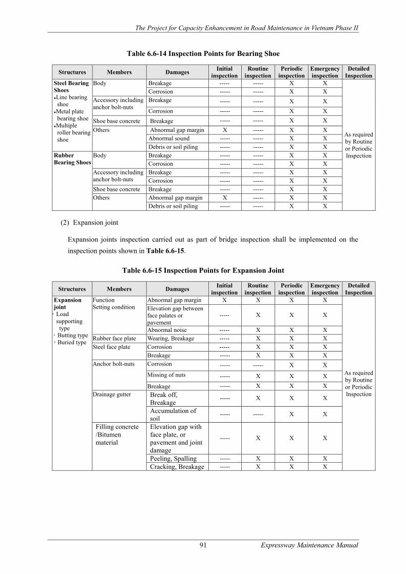
The Project for Capacity Enhancement in Road Maintenance in Vietnam Phase II
91 Expressway Maintenance Manual
Table 6.6-14 Inspection Points for Bearing Shoe
Structures Members Damages Initial
inspection Routine
inspection Periodic
inspection Emergency inspection
Detailed Inspection
Steel Bearing Shoes ●Line bearing
shoe ●Metal plate
bearing shoe ●Multiple
roller bearing shoe
Body Breakage ----- ----- X X
As required by Routine or Periodic Inspection
Corrosion ----- ----- X X Accessory including anchor bolt-nuts
Breakage ----- ----- X X
Corrosion ----- ----- X X
Shoe base concrete Breakage ----- ----- X X
Others Abnormal gap margin X ----- X X Abnormal sound ----- ----- X X
Debris or soil piling ----- ----- X X Rubber Bearing Shoes
Body Breakage ----- ----- X X Corrosion ----- ----- X X
Accessory including anchor bolt-nuts
Breakage ----- ----- X X Corrosion ----- ----- X X
Shoe base concrete Breakage ----- ----- X X Others Abnormal gap margin X ----- X X
Debris or soil piling ----- ----- X X
(2) Expansion joint
Expansion joints inspection carried out as part of bridge inspection shall be implemented on the
inspection points shown in Table 6.6-15.
Table 6.6-15 Inspection Points for Expansion Joint
Structures Members Damages Initial
inspection Routine
inspection Periodic
inspection Emergency inspection
Detailed Inspection
Expansion joint Load
supporting type
Butting type Buried type
Function Setting condition
Abnormal gap margin X X X X
As required by Routine or Periodic Inspection
Elevation gap between face palates or pavement
----- X X X
Abnormal noise ----- X X X Rubber face plate Wearing, Breakage ----- X X X
Steel face plate Corrosion ----- X X X Breakage ----- X X X
Anchor bolt-nuts Corrosion ----- ----- X X
Missing of nuts ----- X X X
Breakage ----- X X X Drainage gutter Break off,
Breakage ----- X X X
Accumulation of soil
----- ----- X X
Filling concrete /Bitumen material
Elevation gap with face plate, or pavement and joint damage
----- X X X
Peeling, Spalling ----- X X X Cracking, Breakage ----- X X X

The Project for Capacity Enhancement in Road Maintenance in Vietnam Phase II
92 Expressway Maintenance Manual
Routine Inspection
Routine inspection shall detect bridge damages, in particular focusing on the damages causing
unsafety to road traffic such as expansion gap, guardrail and handrail, deformation of bridge members
above the road surface, water paddle etc.
Periodic Inspection
Periodic inspection shall cover not only bridge components, members, but also all facilities attached
on the bridge such as traffic safety facilities, traffic control facilities, lighting systems, and pavement
and approach roads including the embankment.
The chief engineer of the Inspection Team shall evaluate the results of inspection, registering data into
the bridge condition database (VBMS) and preparing and submitting inspection reports to the
managing agency of road facility inspection.
Detail Inspection
Detail inspection shall be conducted when proposed by periodic inspection or when proposed for the
planning and the designing of the bridge rehabilitation and reconstruction works. Detailed inspection
shall apply advance inspection equipment and make professional judgement in finding out the causes
of the damages and in planning countermeasures of the damages. The following are the typical tasks
for the detailed inspection.
- Inspection on entire bridge condition
Survey of deflection, settlement, movement and scouring: When some deflection, settlement,
movement or scouring of the bridge is found, it is necessary to conduct detailed survey with
necessary survey equipment. Periodical monitoring of these abnormalities is necessary.
- Inspection on chemical attack
Detecting depth of penetrated salinity contents into concrete: Salinity contents test on collected
concrete powder from each depth is carried out to identify penetration depth of salinity contents
into the concrete.
Detecting depth of penetrated carbon dioxide into concrete: Phenolphthalein solution test on the
collected core/powder from each depth of the concrete is conducted to identify penetration depth
of carbon dioxide into the concrete.
Detecting effect of alkali reaction aggregate: Alkali reaction test on the collected core of the
concrete is carried out. However, actual test method is different according to chemical feature of
the aggregate. Therefore, chemical feature shall be clarified through laboratory test at first. After
then applicable test method will be suggested by chemical researcher.
- Detecting crack on the steel member
To confirm exist of crack on the steel member by;
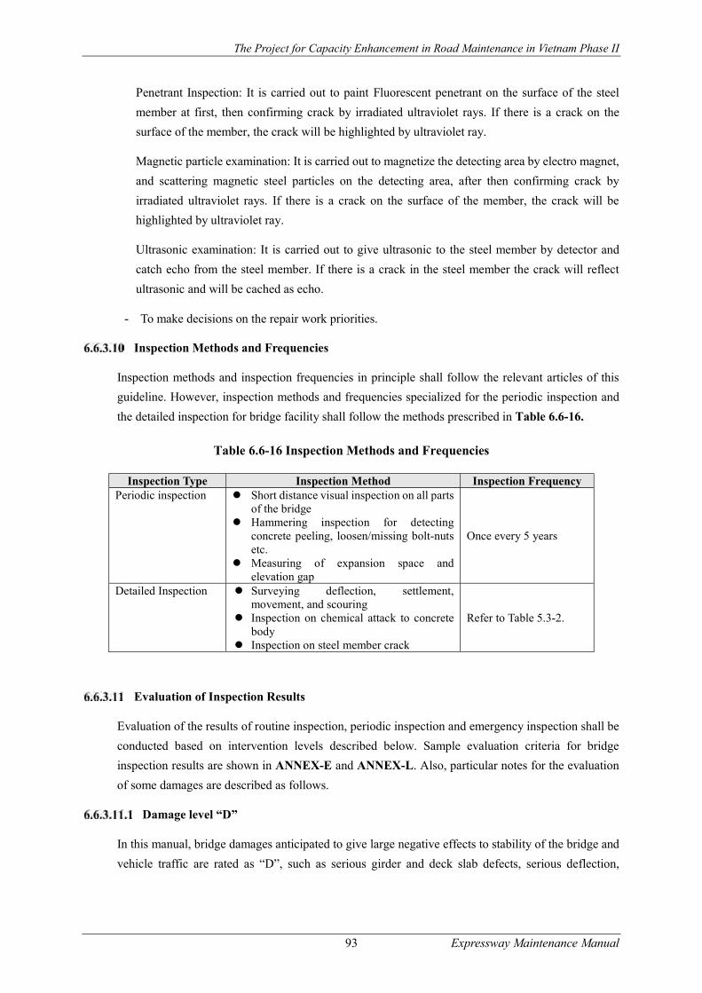
The Project for Capacity Enhancement in Road Maintenance in Vietnam Phase II
93 Expressway Maintenance Manual
Penetrant Inspection: It is carried out to paint Fluorescent penetrant on the surface of the steel
member at first, then confirming crack by irradiated ultraviolet rays. If there is a crack on the
surface of the member, the crack will be highlighted by ultraviolet ray.
Magnetic particle examination: It is carried out to magnetize the detecting area by electro magnet,
and scattering magnetic steel particles on the detecting area, after then confirming crack by
irradiated ultraviolet rays. If there is a crack on the surface of the member, the crack will be
highlighted by ultraviolet ray.
Ultrasonic examination: It is carried out to give ultrasonic to the steel member by detector and
catch echo from the steel member. If there is a crack in the steel member the crack will reflect
ultrasonic and will be cached as echo.
- To make decisions on the repair work priorities.
Inspection Methods and Frequencies
Inspection methods and inspection frequencies in principle shall follow the relevant articles of this
guideline. However, inspection methods and frequencies specialized for the periodic inspection and
the detailed inspection for bridge facility shall follow the methods prescribed in Table 6.6-16.
Table 6.6-16 Inspection Methods and Frequencies
Evaluation of Inspection Results
Evaluation of the results of routine inspection, periodic inspection and emergency inspection shall be
conducted based on intervention levels described below. Sample evaluation criteria for bridge
inspection results are shown in ANNEX-E and ANNEX-L. Also, particular notes for the evaluation
of some damages are described as follows.
Damage level “D”
In this manual, bridge damages anticipated to give large negative effects to stability of the bridge and
vehicle traffic are rated as “D”, such as serious girder and deck slab defects, serious deflection,
Inspection Type Inspection Method Inspection Frequency Periodic inspection Short distance visual inspection on all parts
of the bridge Hammering inspection for detecting
concrete peeling, loosen/missing bolt-nuts etc.
Measuring of expansion space and elevation gap
Once every 5 years
Detailed Inspection Surveying deflection, settlement, movement, and scouring
Inspection on chemical attack to concrete body
Inspection on steel member crack
Refer to Table 5.3-2.
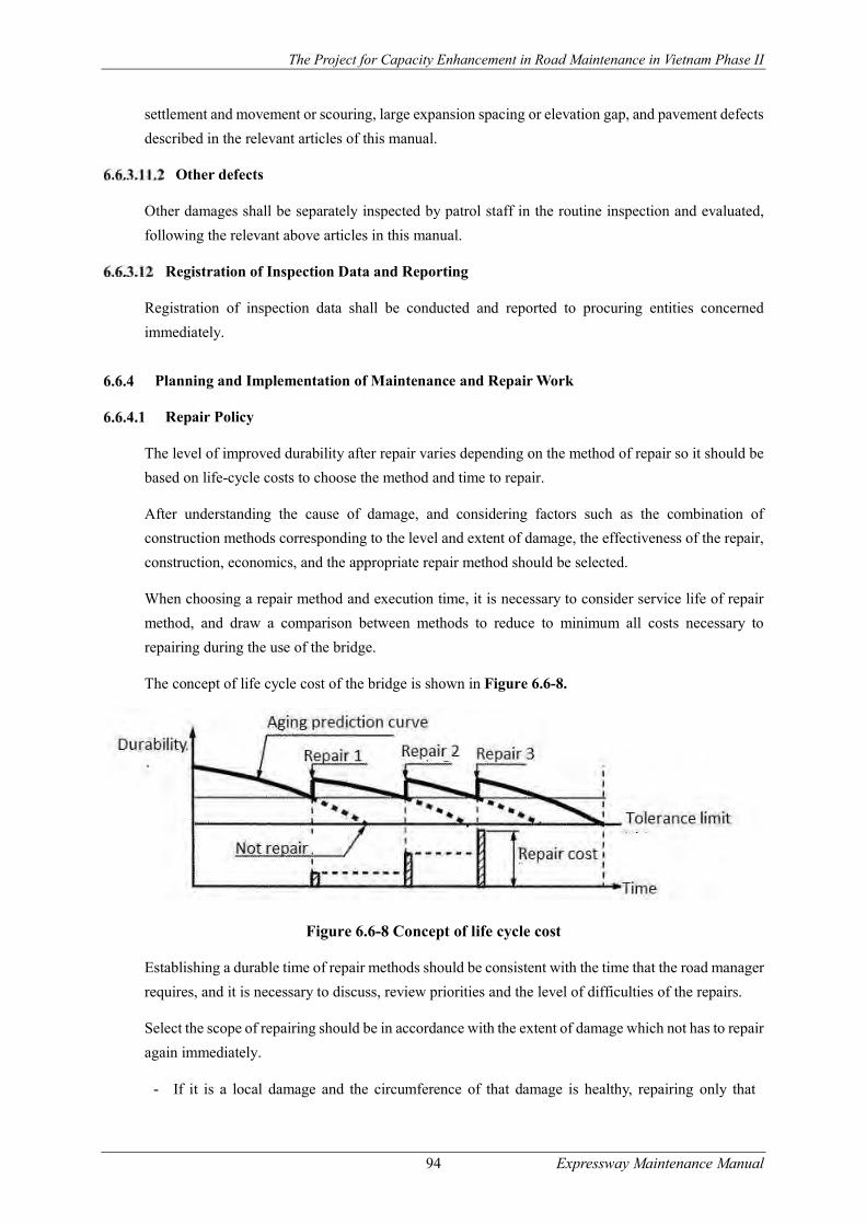
The Project for Capacity Enhancement in Road Maintenance in Vietnam Phase II
94 Expressway Maintenance Manual
settlement and movement or scouring, large expansion spacing or elevation gap, and pavement defects
described in the relevant articles of this manual.
Other defects
Other damages shall be separately inspected by patrol staff in the routine inspection and evaluated,
following the relevant above articles in this manual.
Registration of Inspection Data and Reporting
Registration of inspection data shall be conducted and reported to procuring entities concerned
immediately.
Planning and Implementation of Maintenance and Repair Work
Repair Policy
The level of improved durability after repair varies depending on the method of repair so it should be
based on life-cycle costs to choose the method and time to repair.
After understanding the cause of damage, and considering factors such as the combination of
construction methods corresponding to the level and extent of damage, the effectiveness of the repair,
construction, economics, and the appropriate repair method should be selected.
When choosing a repair method and execution time, it is necessary to consider service life of repair
method, and draw a comparison between methods to reduce to minimum all costs necessary to
repairing during the use of the bridge.
The concept of life cycle cost of the bridge is shown in Figure 6.6-8.
Figure 6.6-8 Concept of life cycle cost
Establishing a durable time of repair methods should be consistent with the time that the road manager
requires, and it is necessary to discuss, review priorities and the level of difficulties of the repairs.
Select the scope of repairing should be in accordance with the extent of damage which not has to repair
again immediately.
- If it is a local damage and the circumference of that damage is healthy, repairing only that
The Project for Capacity Enhancement in Road Maintenance in Vietnam Phase II
95 Expressway Maintenance Manual
damage is enough.
- In case of continuous damage affecting adjacent and if it is ignored, the damage will spread and
it is necessary to repair whole the damaged area.
When choosing the method of repair, it is necessary to understand the cause of damage in order to
select the repair method which is appropriate with that damage.
When making surface covering, it is necessary to pay attention to color and scope of repair in order
not make bad influence on the surrounding landscape.
Whether damage is still developed repaired places, it is necessary to check the repaired place regularly,
and record the problems and the durability of the repair methods. The recording data is very important
to streamline the maintenance management of bridge hereafter.
Particularly, whether to use the new repair technology according to the development of new
technologies in recent years, but it is necessary to review carefully to verify the durability of the repair
methods.
If the damage is caused by the lack of structural details and the structural durability, even if repaired,
it would still be damaged easily. So it is necessary to strengthen the structures before repairing.
Repairing methods of steel structures
Repairing methods selection
When carrying out repair of steel structures, it must consider conditions such as traffic restrictions in
the welding position, measures to prevent wind, measures to reduce moist, and must consider the
safety of the bridge which was designed such as load capacity while exchanging steel materials, and
consideration of construction, capacity of the bridge after repair.
In the typical repair methods of steel structure, there are the following methods:
- Crack repair methods include: welding repair, stop-hole, cover-sheet and shape improvement
method
- Element replacement methods include: high strength bolt replacement, whole element
replacement, and partial element replacement method
- The heat straightening method
- The paint refinishing method
- The waterproofing method
The causes of damage and repair methods of steel structure are shown in Table 6.6-17.
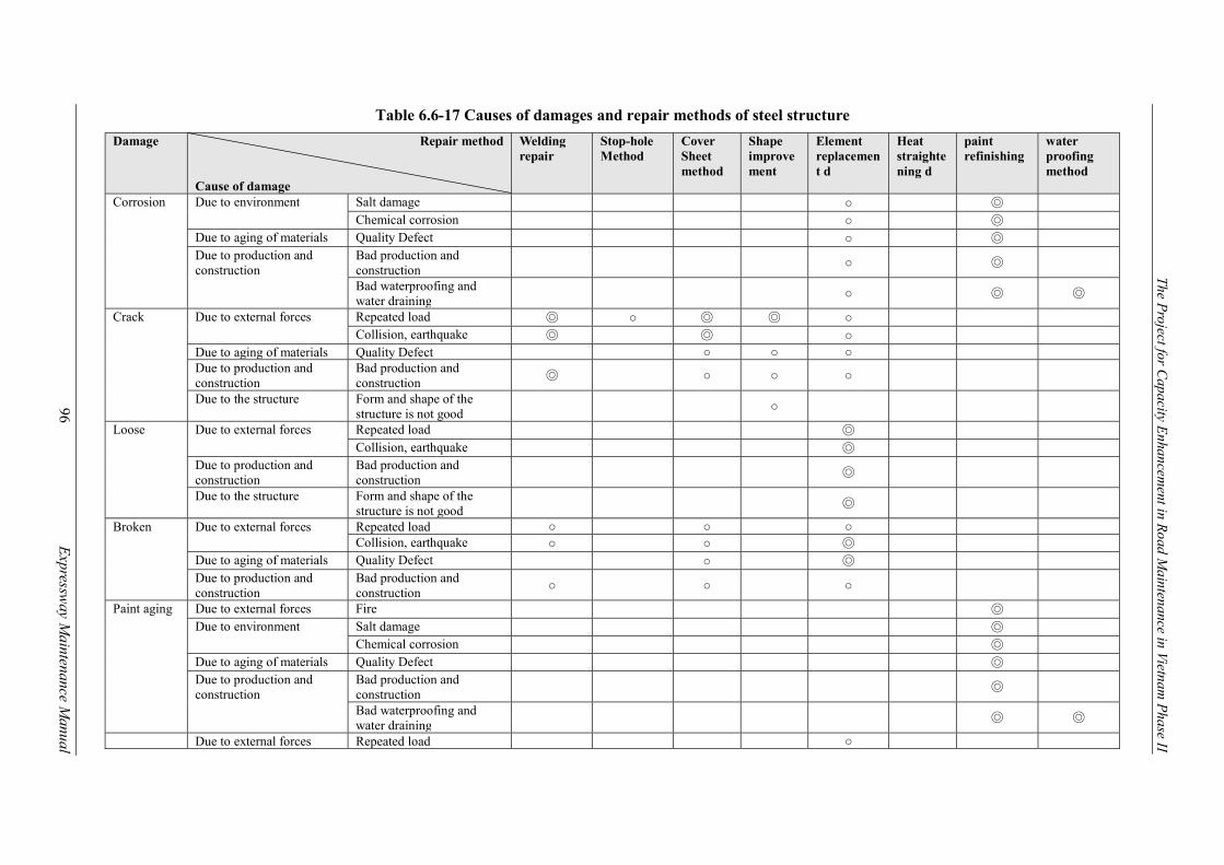
The Project for C
apacity Enhancem
ent in Road M
aintenance in Vietnam P
hase II
96
E
xpressway M
aintenance Manual
Table 6.6-17 Causes of damages and repair methods of steel structure
Damage Repair method Cause of damage
Welding repair
Stop-hole Method
Cover Sheet method
Shape improvement
Element replacement d
Heat straightening d
paint refinishing
water proofing method
Corrosion Due to environment Salt damage ○ ◎ Chemical corrosion ○ ◎
Due to aging of materials Quality Defect ○ ◎ Due to production and construction
Bad production and construction
○ ◎
Bad waterproofing and water draining
○ ◎ ◎
Crack Due to external forces Repeated load ◎ ○ ◎ ◎ ○ Collision, earthquake ◎ ◎ ○
Due to aging of materials Quality Defect ○ ○ ○ Due to production and construction
Bad production and construction
◎ ○ ○ ○
Due to the structure Form and shape of the structure is not good
○
Loose Due to external forces Repeated load ◎ Collision, earthquake ◎
Due to production and construction
Bad production and construction
◎
Due to the structure Form and shape of the structure is not good
◎
Broken Due to external forces Repeated load ○ ○ ○ Collision, earthquake ○ ○ ◎
Due to aging of materials Quality Defect ○ ◎ Due to production and construction
Bad production and construction
○ ○ ○
Paint aging Due to external forces Fire ◎ Due to environment Salt damage ◎
Chemical corrosion ◎ Due to aging of materials Quality Defect ◎ Due to production and construction
Bad production and construction
◎
Bad waterproofing and water draining
◎ ◎
Due to external forces Repeated load ○

The Project for C
apacity Enhancem
ent in Road M
aintenance in Vietnam P
hase II
97
E
xpressway M
aintenance Manual
Damage Repair method Cause of damage
Welding repair
Stop-hole Method
Cover Sheet method
Shape improvement
Element replacement d
Heat straightening d
paint refinishing
water proofing method
De-formation
Collision, earthquake, fire ◎ ○ Due to production and construction
Bad production and construction
○
Ab-normal shock
Due to external forces Repeated load ○ Earthquake ○
Due to production and construction
Bad production and construction
○
(Note) ◎: Extremely effective ○: Effective

The Project for Capacity Enhancement in Road Maintenance in Vietnam Phase II
98 Expressway Maintenance Manual
Crack treatment
(1) The welding repair method
Use arc air gouging to smooth cracks at the welding position, weld it, and then finish fully the top end
of the welding. When cracks are repaired by welding, it is necessary to note the following points:
- The cause of cracks: Because fatigue cracks occurred by stress concentration and occurrence of
secondary stress, the welding repair should be conducted after fixing the causes of cracks.
- If the cause of cracks is bad welding work, it means after welding repair, cracks will certainly
be improved than before, so just repairing by welding is enough.
- Because welding repair is on-site work, when it is carried in special locations which are difficult
of impossible to weld, it can be easy to make weld defects and/or uncompleted repair.
- To increase fatigue strength, the top end of welding should be finished by TIG or grinding.
Figure 6.6-9 Welding repair method
(2) The Stop-hole Method
Create a round hole at the tip of the crack to remove the stress concentration of the tip of the crack and
prevent the spread of the crack.
This method is used much as a first aid measure, but is also used to prevent the spread of cracks.
Initiation stress at the tip of the crack when stop-hole is effective will reach to 50N/mm2 compared
with the nominal in-plane stress.
Figure 6.6-10 Stop-hole Method
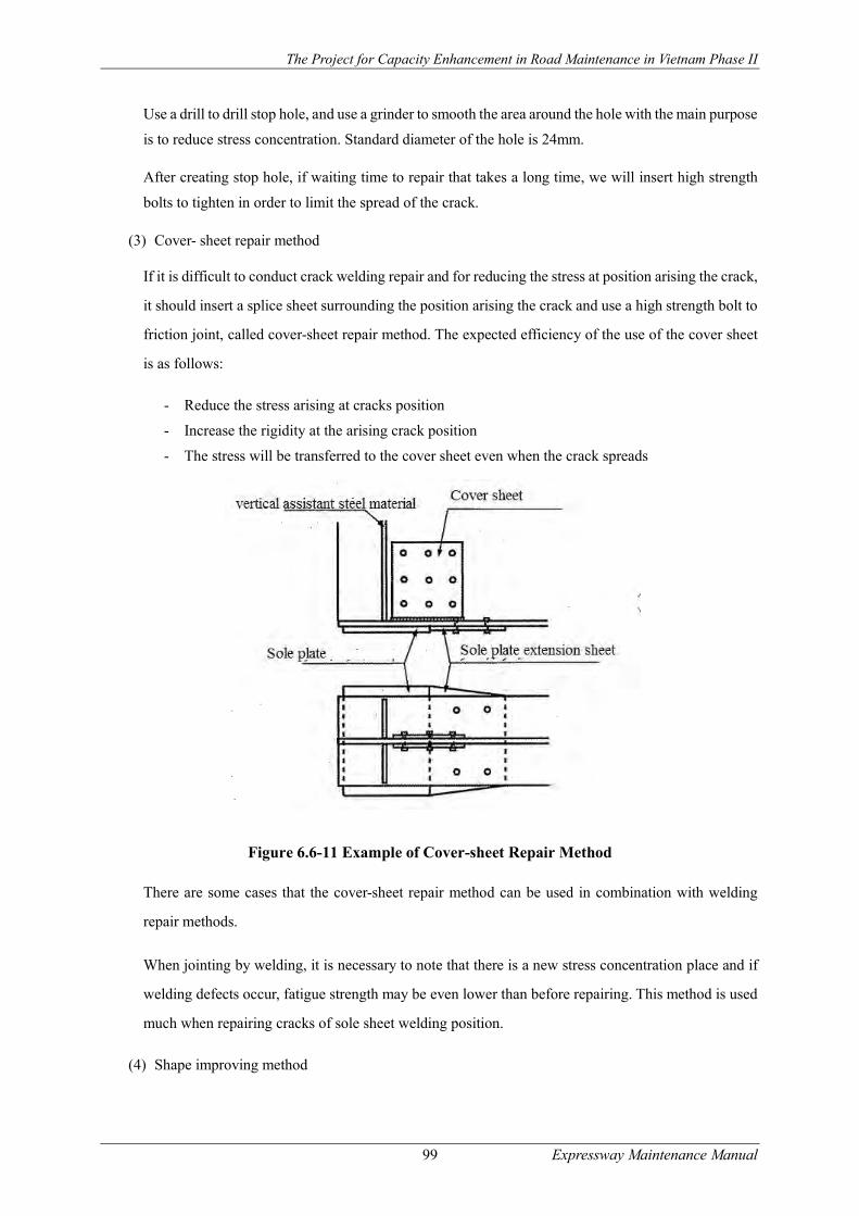
The Project for Capacity Enhancement in Road Maintenance in Vietnam Phase II
99 Expressway Maintenance Manual
Use a drill to drill stop hole, and use a grinder to smooth the area around the hole with the main purpose
is to reduce stress concentration. Standard diameter of the hole is 24mm.
After creating stop hole, if waiting time to repair that takes a long time, we will insert high strength
bolts to tighten in order to limit the spread of the crack.
(3) Cover- sheet repair method
If it is difficult to conduct crack welding repair and for reducing the stress at position arising the crack,
it should insert a splice sheet surrounding the position arising the crack and use a high strength bolt to
friction joint, called cover-sheet repair method. The expected efficiency of the use of the cover sheet
is as follows:
- Reduce the stress arising at cracks position
- Increase the rigidity at the arising crack position
- The stress will be transferred to the cover sheet even when the crack spreads
Figure 6.6-11 Example of Cover-sheet Repair Method
There are some cases that the cover-sheet repair method can be used in combination with welding
repair methods.
When jointing by welding, it is necessary to note that there is a new stress concentration place and if
welding defects occur, fatigue strength may be even lower than before repairing. This method is used
much when repairing cracks of sole sheet welding position.
(4) Shape improving method

The Project for Capacity Enhancement in Road Maintenance in Vietnam Phase II
100 Expressway Maintenance Manual
If cracks occur at the top end of the welding after removing cracks, we grind the shape of the top end
of the welding, smoothen by TIG welding and reduce stress concentration.
Figure 6.6-12 Example of repairing small cracks by shape improving method
This method will be effective if the cause of cracks is fatigue caused by stress concentration arising
from the shape of the welding.
If the crack is small and the stress concentration of the crack is low, it is unnecessary to weld again
the position removed the crack.
Replacing Methods
(1) The high strength bolt replacing method
High strength bolt replacement method is removing broken bolts and rivets of coupling joints and
exchange them by new high strength bolts. The method also is used in case of bolts are dropped out
or missing. Joint mechanism of rivet and bolt are different. The rivet is bearing pressure joint, and the
bolt is friction joint. Replacing a part of rivets with high strength bolts can form admixture of different
joints, so it is necessary to check the joints for safety.
In case of replacing all the bolts and rivets of the joints, it should leave the bolts needed for joints and
exchange one by one.
As other cases, when there is a gap part between base materials of the back side of the cover sheet, it
is necessary to check and replace the cover sheet also if the cover sheet is corroded and the cross
section is damaged.
(2) The method of replacing the entire materials
If the secondary materials are damaged by corrosion and the damage of the cross section is severe, it
should remove all damaged materials and replace them by new materials.
In case of secondary material is damaged, in order to ensure the safety of the entire bridge, replacing
the entire materials is much more optimal than repairing parts.
When replacing the entire materials, it is necessary to check and consider method statement to ensure
safety when materials are removed.
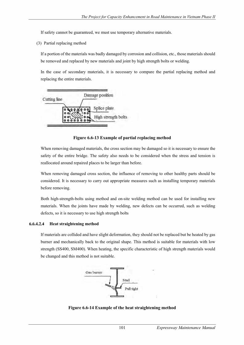
The Project for Capacity Enhancement in Road Maintenance in Vietnam Phase II
101 Expressway Maintenance Manual
If safety cannot be guaranteed, we must use temporary alternative materials.
(3) Partial replacing method
If a portion of the materials was badly damaged by corrosion and collision, etc., those materials should
be removed and replaced by new materials and joint by high strength bolts or welding.
In the case of secondary materials, it is necessary to compare the partial replacing method and
replacing the entire materials.
Figure 6.6-13 Example of partial replacing method
When removing damaged materials, the cross section may be damaged so it is necessary to ensure the
safety of the entire bridge. The safety also needs to be considered when the stress and tension is
reallocated around repaired places to be larger than before.
When removing damaged cross section, the influence of removing to other healthy parts should be
considered. It is necessary to carry out appropriate measures such as installing temporary materials
before removing.
Both high-strength-bolts using method and on-site welding method can be used for installing new
materials. When the joints have made by welding, new defects can be occurred, such as welding
defects, so it is necessary to use high strength bolts
Heat straightening method
If materials are collided and have slight deformation, they should not be replaced but be heated by gas
burner and mechanically back to the original shape. This method is suitable for materials with low
strength (SS400, SM400). When heating, the specific characteristic of high strength materials would
be changed and this method is not suitable.
Figure 6.6-14 Example of the heat straightening method
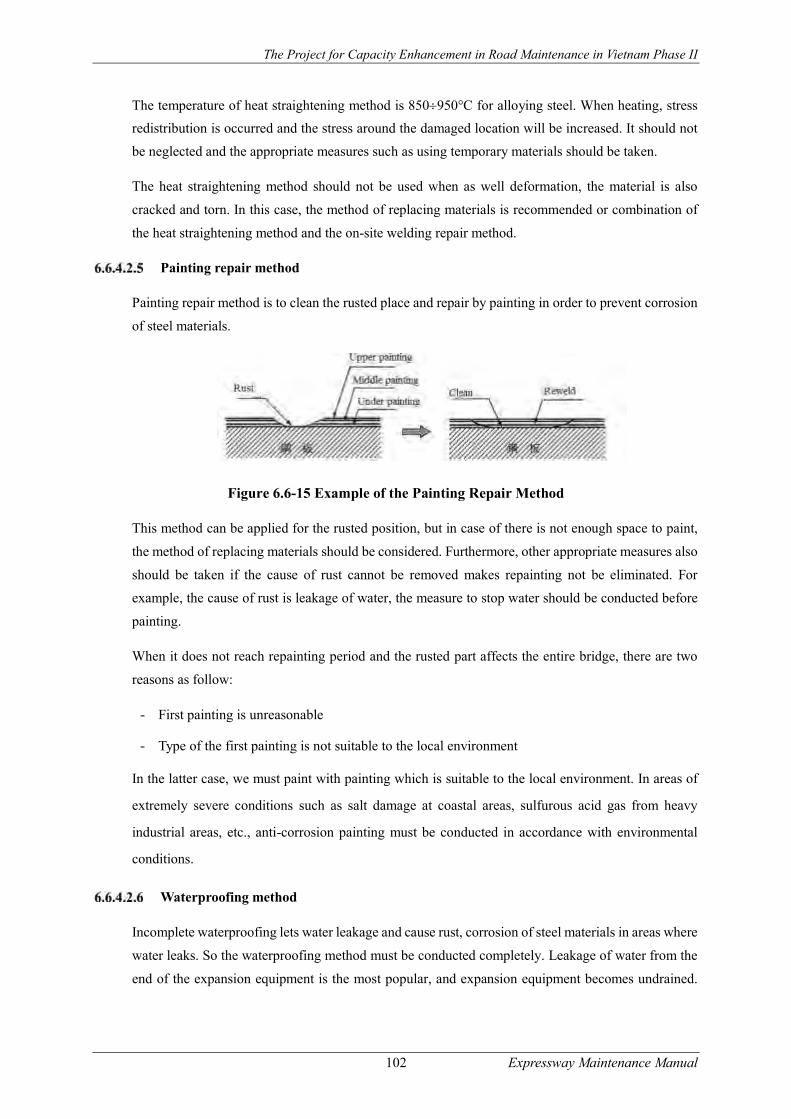
The Project for Capacity Enhancement in Road Maintenance in Vietnam Phase II
102 Expressway Maintenance Manual
The temperature of heat straightening method is 850950°C for alloying steel. When heating, stress
redistribution is occurred and the stress around the damaged location will be increased. It should not
be neglected and the appropriate measures such as using temporary materials should be taken.
The heat straightening method should not be used when as well deformation, the material is also
cracked and torn. In this case, the method of replacing materials is recommended or combination of
the heat straightening method and the on-site welding repair method.
Painting repair method
Painting repair method is to clean the rusted place and repair by painting in order to prevent corrosion
of steel materials.
Figure 6.6-15 Example of the Painting Repair Method
This method can be applied for the rusted position, but in case of there is not enough space to paint,
the method of replacing materials should be considered. Furthermore, other appropriate measures also
should be taken if the cause of rust cannot be removed makes repainting not be eliminated. For
example, the cause of rust is leakage of water, the measure to stop water should be conducted before
painting.
When it does not reach repainting period and the rusted part affects the entire bridge, there are two
reasons as follow:
- First painting is unreasonable
- Type of the first painting is not suitable to the local environment
In the latter case, we must paint with painting which is suitable to the local environment. In areas of
extremely severe conditions such as salt damage at coastal areas, sulfurous acid gas from heavy
industrial areas, etc., anti-corrosion painting must be conducted in accordance with environmental
conditions.
Waterproofing method
Incomplete waterproofing lets water leakage and cause rust, corrosion of steel materials in areas where
water leaks. So the waterproofing method must be conducted completely. Leakage of water from the
end of the expansion equipment is the most popular, and expansion equipment becomes undrained.

The Project for Capacity Enhancement in Road Maintenance in Vietnam Phase II
103 Expressway Maintenance Manual
When water leakage is observed, it must be quickly repaired. Water leaks from floor also corrode steel
materials. So the leaked floor should be provided by waterproofing equipment.
Figure 6.6-16 Example of waterproofing method
The damages of drainage equipment will cause corrosion of steel materials. They should be quickly
repaired.
Repair methods for concrete structure
Repair method selection
There are many cases in which the damage of concrete and the cause of damage are complicated, so
it is necessary to select a method that is appropriate for any damage. Furthermore, if different damage
is contiguous, we must choose a repair method which can counter any damage.
For the cases such as the damage is on a large scale, the method of replacing entire materials with the
new one would be used after considering the issues of economy and construction.
There are typical methods for repairing concrete structure as follows:
- Crack repair methods: surface treatment method and crack infusion method
- Cross section repair method: cross section mortar method, prepacked concrete method
- Method of replacement parts
- Surface cover method: the method of covering surface with paint, the method of covering
surface aims to prevent peeling paint
- Reinforcing bar anti-rust method: anti-rust treatment method, the method of changing titanium
to anode to prevent electric corrosion, the method of changing zinc to anode to prevent electric
corrosion.
- Desalting method: (Electro chemical desalting method)
- Re-alkali method (Electrochemical re-alkali method)
- Waterproofing method, water stopping method
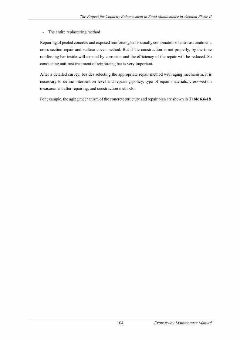
The Project for Capacity Enhancement in Road Maintenance in Vietnam Phase II
104 Expressway Maintenance Manual
- The entire replastering method
Repairing of peeled concrete and exposed reinforcing bar is usually combination of anti-rust treatment,
cross section repair and surface cover method. But if the construction is not properly, by the time
reinforcing bar inside will expand by corrosion and the efficiency of the repair will be reduced. So
conducting anti-rust treatment of reinforcing bar is very important.
After a detailed survey, besides selecting the appropriate repair method with aging mechanism, it is
necessary to define intervention level and repairing policy, type of repair materials, cross-section
measurement after repairing, and construction methods.
For example, the aging mechanism of the concrete structure and repair plan are shown in Table 6.6-18 .

The Project for C
apacity Enhancem
ent in Road M
aintenance in Vietnam P
hase II
105
Expressw
ay Maintenance M
anual
Table 6.6-18 Examples of aging mechanisms and repair plan
Aging mechanisms Repair policies Possibly appropriate repair methods Factors need to consider in order to reach repair standard Neutralization - Remove the neutral concrete
- Restraint the infiltration of CO2 and water after repairing
Cross section repair method Surface cover method Re-alkali method
- Degree of removal of neutral concrete - Anti-rust treatment of reinforcing bar - Quality and thickness of surface cover materials
Salt damage - Remove infiltrated Cl- - Remove aging concrete - Restraint the infiltration of CO2 and water after repairing
Cross section repair method Surface cover method Desalting method
- Degree of removal of the infiltrated Cl- - Anti-rust treatment of reinforcing bar - Quality and thickness of surface cover materials -
- Control electrical potential of reinforcing bar
Prevent electric corrosion Quality and polarization quantity of anode materials
Frost damage - Remove aging concrete - Restraint the infiltration of water after repairing - Improve freeze-thaw resistance of concrete
Cross section repair method Crack infusion method Surface cover method
- Freeze-thaw resistance of cross section repair materials - Quality of crack infusion materials and construction method - Quality and thickness of surface cover materials
Chemical corrosion - Remove aging concrete - Restraint the infiltration of harmful chemical materials
Cross section repair method Surface cover method
- Quality and thickness of surface cover materials - Degree of removal of aging concrete
Alkali-aggregate reaction - Restraint the supply of water - Increase the dissipation of water inside - Restraint the supply of alkali
Crack infusion method Surface cover method
- Quality of crack infusion materials and construction method - Quality and thickness of surface cover materials
Overload - Control the spread of cracks
(Note) Cl: Ion Chloride; CO2: Carbon Dioxide Causes of damage of concrete structure and repair methods are shown in Table 6.6-19
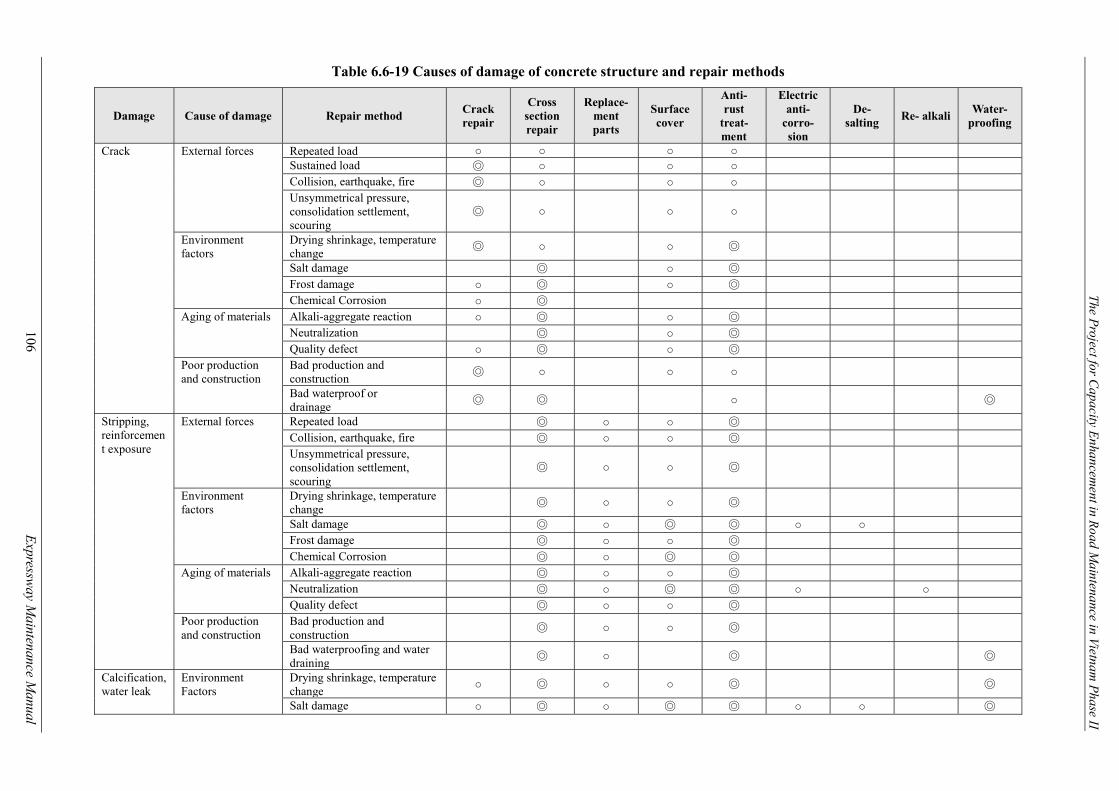
The Project for C
apacity Enhancem
ent in Road M
aintenance in Vietnam P
hase II
106
Expressw
ay Maintenance M
anual
Table 6.6-19 Causes of damage of concrete structure and repair methods
Damage Cause of damage Repair method Crack repair
Cross section repair
Replace-ment parts
Surface cover
Anti- rust
treat- ment
Electric anti-
corro- sion
De- salting
Re- alkali Water-
proofing
Crack External forces Repeated load ○ ○ ○ ○ Sustained load ◎ ○ ○ ○ Collision, earthquake, fire ◎ ○ ○ ○ Unsymmetrical pressure, consolidation settlement, scouring
◎ ○ ○ ○
Environment factors
Drying shrinkage, temperature change
◎ ○ ○ ◎
Salt damage ◎ ○ ◎ Frost damage ○ ◎ ○ ◎ Chemical Corrosion ○ ◎
Aging of materials Alkali-aggregate reaction ○ ◎ ○ ◎ Neutralization ◎ ○ ◎ Quality defect ○ ◎ ○ ◎
Poor production and construction
Bad production and construction
◎ ○ ○ ○
Bad waterproof or drainage
◎ ◎ ○ ◎
Stripping, reinforcement exposure
External forces Repeated load ◎ ○ ○ ◎ Collision, earthquake, fire ◎ ○ ○ ◎ Unsymmetrical pressure, consolidation settlement, scouring
◎ ○ ○ ◎
Environment factors
Drying shrinkage, temperature change
◎ ○ ○ ◎
Salt damage ◎ ○ ◎ ◎ ○ ○ Frost damage ◎ ○ ○ ◎ Chemical Corrosion ◎ ○ ◎ ◎
Aging of materials Alkali-aggregate reaction ◎ ○ ○ ◎ Neutralization ◎ ○ ◎ ◎ ○ ○ Quality defect ◎ ○ ○ ◎
Poor production and construction
Bad production and construction
◎ ○ ○ ◎
Bad waterproofing and water draining
◎ ○ ◎ ◎
Calcification, water leak
Environment Factors
Drying shrinkage, temperature change
○ ◎ ○ ○ ◎ ◎
Salt damage ○ ◎ ○ ◎ ◎ ○ ○ ◎
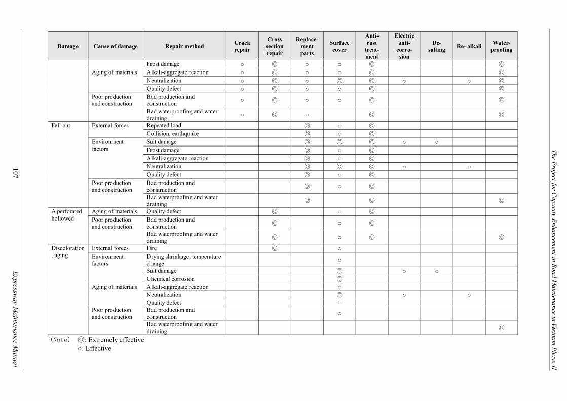
The Project for C
apacity Enhancem
ent in Road M
aintenance in Vietnam P
hase II
107
Expressw
ay Maintenance M
anual
Damage Cause of damage Repair method Crack repair
Cross section repair
Replace-ment parts
Surface cover
Anti- rust
treat- ment
Electric anti-
corro- sion
De- salting
Re- alkali Water-
proofing
Frost damage ○ ◎ ○ ○ ◎ ◎ Aging of materials Alkali-aggregate reaction ○ ◎ ○ ○ ◎ ◎
Neutralization ○ ◎ ○ ◎ ◎ ○ ○ ◎ Quality defect ○ ◎ ○ ○ ◎ ◎
Poor production and construction
Bad production and construction
○ ◎ ○ ○ ◎ ◎
Bad waterproofing and water draining
○ ◎ ○ ◎ ◎
Fall out External forces Repeated load ◎ ○ ◎ Collision, earthquake ◎ ○ ◎
Environment factors
Salt damage ◎ ◎ ◎ ○ ○ Frost damage ◎ ○ ◎ Alkali-aggregate reaction ◎ ○ ◎ Neutralization ◎ ◎ ◎ ○ ○ Quality defect ◎ ○ ◎
Poor production and construction
Bad production and construction
◎ ○ ◎
Bad waterproofing and water draining
◎ ◎ ◎
A perforated hollowed
Aging of materials Quality defect ◎ ○ ◎ Poor production and construction
Bad production and construction
◎ ○ ◎
Bad waterproofing and water draining
◎ ○ ◎ ◎
Discoloration, aging
External forces Fire ◎ ○ Environment factors
Drying shrinkage, temperature change
○
Salt damage ◎ ○ ○ Chemical corrosion ◎
Aging of materials Alkali-aggregate reaction ○ Neutralization ◎ ○ ○ Quality defect ○
Poor production and construction
Bad production and construction
○
Bad waterproofing and water draining
◎
(Note) ◎: Extremely effective ○: Effective
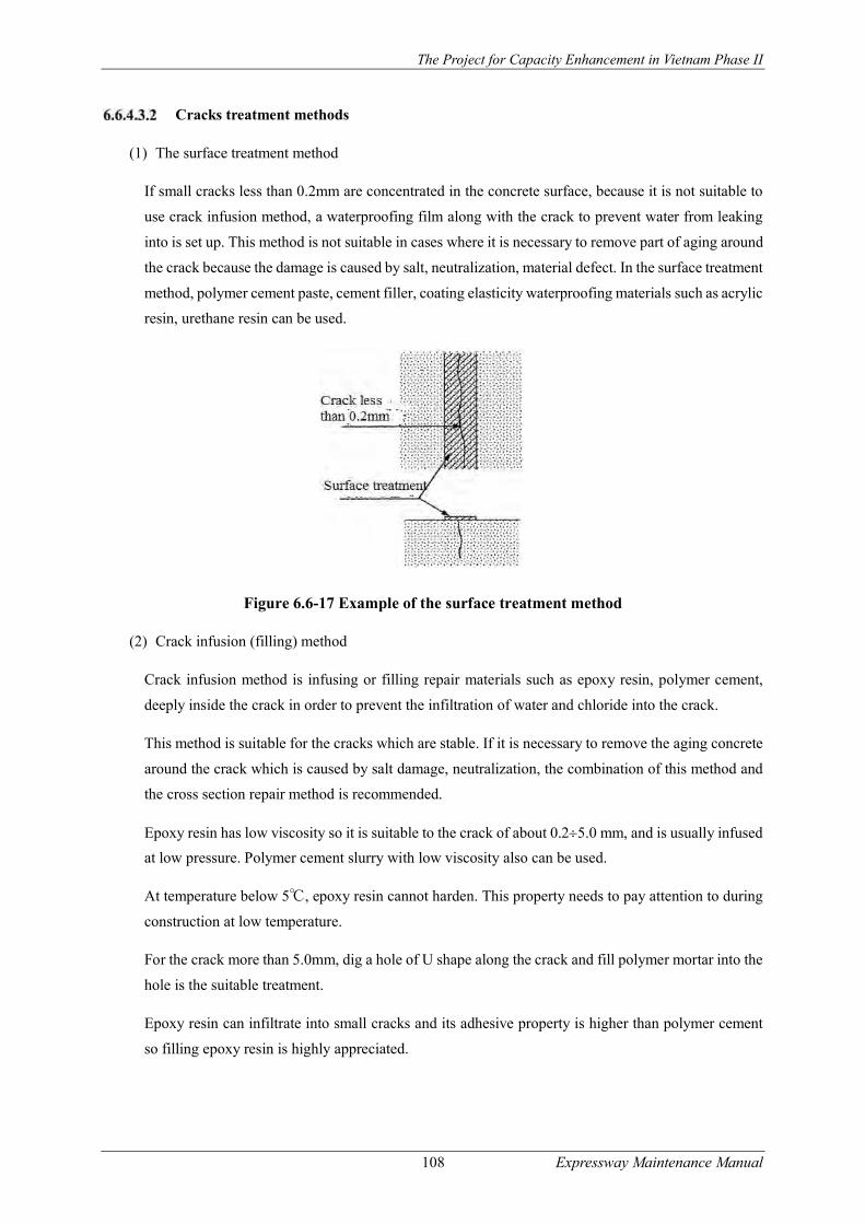
The Project for Capacity Enhancement in Vietnam Phase II
108 Expressway Maintenance Manual
Cracks treatment methods
(1) The surface treatment method
If small cracks less than 0.2mm are concentrated in the concrete surface, because it is not suitable to
use crack infusion method, a waterproofing film along with the crack to prevent water from leaking
into is set up. This method is not suitable in cases where it is necessary to remove part of aging around
the crack because the damage is caused by salt, neutralization, material defect. In the surface treatment
method, polymer cement paste, cement filler, coating elasticity waterproofing materials such as acrylic
resin, urethane resin can be used.
Figure 6.6-17 Example of the surface treatment method
(2) Crack infusion (filling) method
Crack infusion method is infusing or filling repair materials such as epoxy resin, polymer cement,
deeply inside the crack in order to prevent the infiltration of water and chloride into the crack.
This method is suitable for the cracks which are stable. If it is necessary to remove the aging concrete
around the crack which is caused by salt damage, neutralization, the combination of this method and
the cross section repair method is recommended.
Epoxy resin has low viscosity so it is suitable to the crack of about 0.25.0 mm, and is usually infused
at low pressure. Polymer cement slurry with low viscosity also can be used.
At temperature below 5℃, epoxy resin cannot harden. This property needs to pay attention to during
construction at low temperature.
For the crack more than 5.0mm, dig a hole of U shape along the crack and fill polymer mortar into the
hole is the suitable treatment.
Epoxy resin can infiltrate into small cracks and its adhesive property is higher than polymer cement
so filling epoxy resin is highly appreciated.

The Project for Capacity Enhancement in Vietnam Phase II
109 Expressway Maintenance Manual
For spreading cracks, it is difficult for materials adhere to the expansion of the cracks, so the crack
infusion method is not recommended. If the infusion method is forced to use for spreading crack repair,
it must ensure enough materials to absorb the width of the cracks and fill elastic seat into the cracks.
When infusing resin, it is unsuitable to construct in areas with serious water leakage. For repairing the
crack at these areas, inorganic cement crystal should be used to increase material to stop water. In this
case, repairing materials will react with water in the concrete and produce a cement crystal. This
crystallization makes the impermeability of the entire cement.
Figure 6.6-18 Example of the crack injecting, (a) and (c), and filling method (b)
Cross section repair methods
(1) Cross section repair mortar method
Cross section repair mortar method is the method of using trowel, spatula to paint the damaged part
of cross section by repair materials many times. This method is also called mortar patching method.
This method is used when the cross-section damage is relatively small and the repair depth is below
5cm. When construction condition is convenient which provide sufficient working space, this method
can be used at all positions. The materials are used for cross section repair mortar method as polymer
cement mortar, concrete, epoxy resin mortar, uncontrived mortar.
- Polymer cement mortar or concrete is cheap, efficient to neutralization and can be worked in
wet conditions.
- Polymer SBR has good long-term adhesive property, and PAE polymer has good initial adhesive
property.
- Epoxy resin mortar is expensive in comparison with polymer but because of the good adhesion,
it is suitable to repair the cross section of relatively thin layer of about 612mm. However, it
should not be used at low temperatures of less than 50 C because cannot harden.
- Non-shrinking mortar has thick coating so it is suitable to repair the relatively large cross section.
But in comparison with other materials, it has weak adhesion and needs the hydraulic
environment.
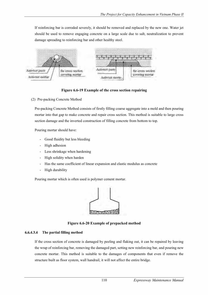
The Project for Capacity Enhancement in Vietnam Phase II
110 Expressway Maintenance Manual
If reinforcing bar is corroded severely, it should be removed and replaced by the new one. Water jet
should be used to remove engaging concrete on a large scale due to salt, neutralization to prevent
damage spreading to reinforcing bar and other healthy steel.
Figure 6.6-19 Example of the cross section repairing
(2) Pre-packing Concrete Method
Pre-packing Concrete Method consists of firstly filling coarse aggregate into a mold and then pouring
mortar into that gap to make concrete and repair cross section. This method is suitable to large cross
section damage and the inverted construction of filling concrete from bottom to top.
Pouring mortar should have:
- Good fluidity but less bleeding
- High adhesion
- Less shrinkage when hardening
- High solidity when harden
- Has the same coefficient of linear expansion and elastic modulus as concrete
- High durability
Pouring mortar which is often used is polymer cement mortar.
Figure 6.6-20 Example of prepacked method
The partial filling method
If the cross section of concrete is damaged by peeling and flaking out, it can be repaired by leaving
the wrap of reinforcing bar, removing the damaged part, setting new reinforcing bar, and pouring new
concrete mortar. This method is suitable to the damages of components that even if remove the
structure built as floor system, wall handrail, it will not affect the entire bridge.
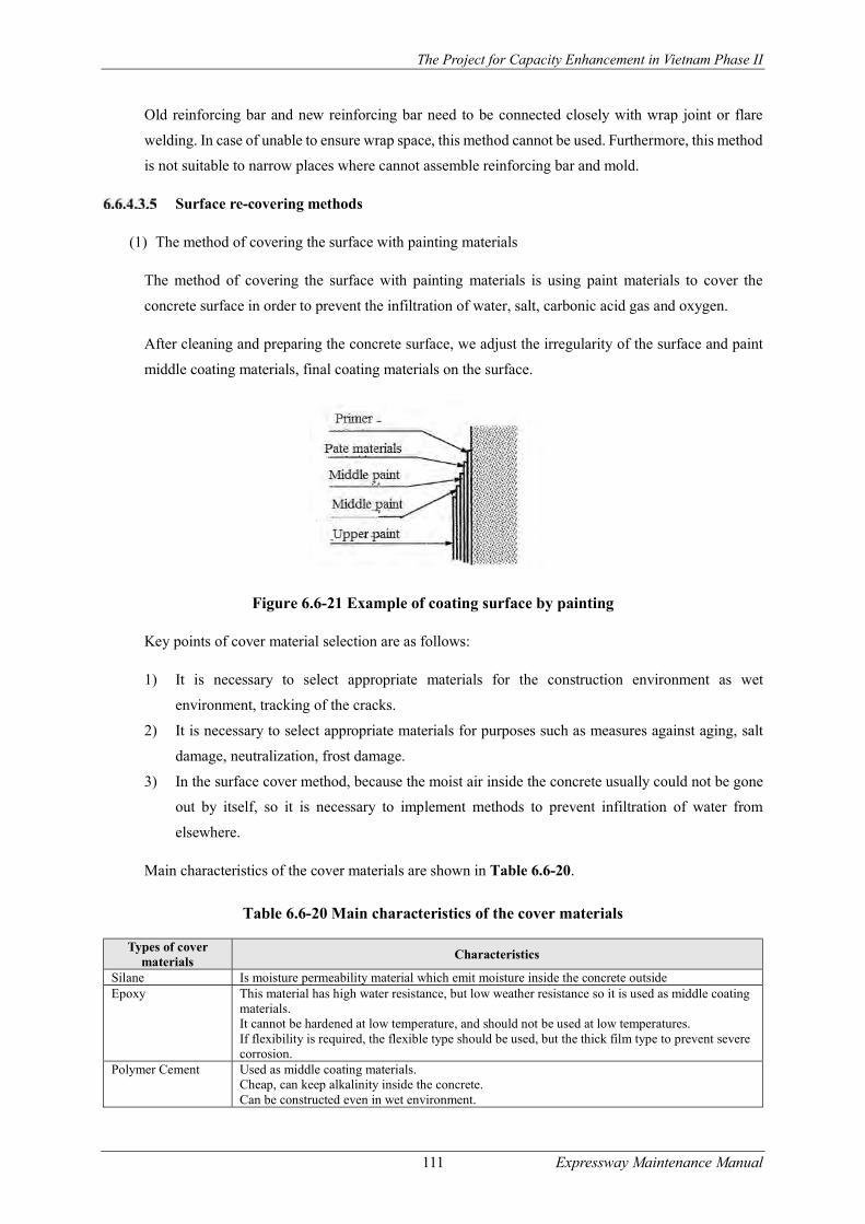
The Project for Capacity Enhancement in Vietnam Phase II
111 Expressway Maintenance Manual
Old reinforcing bar and new reinforcing bar need to be connected closely with wrap joint or flare
welding. In case of unable to ensure wrap space, this method cannot be used. Furthermore, this method
is not suitable to narrow places where cannot assemble reinforcing bar and mold.
Surface re-covering methods
(1) The method of covering the surface with painting materials
The method of covering the surface with painting materials is using paint materials to cover the
concrete surface in order to prevent the infiltration of water, salt, carbonic acid gas and oxygen.
After cleaning and preparing the concrete surface, we adjust the irregularity of the surface and paint
middle coating materials, final coating materials on the surface.
Figure 6.6-21 Example of coating surface by painting
Key points of cover material selection are as follows:
1) It is necessary to select appropriate materials for the construction environment as wet
environment, tracking of the cracks.
2) It is necessary to select appropriate materials for purposes such as measures against aging, salt
damage, neutralization, frost damage.
3) In the surface cover method, because the moist air inside the concrete usually could not be gone
out by itself, so it is necessary to implement methods to prevent infiltration of water from
elsewhere.
Main characteristics of the cover materials are shown in Table 6.6-20.
Table 6.6-20 Main characteristics of the cover materials
Types of cover materials
Characteristics
Silane Is moisture permeability material which emit moisture inside the concrete outside Epoxy This material has high water resistance, but low weather resistance so it is used as middle coating
materials. It cannot be hardened at low temperature, and should not be used at low temperatures. If flexibility is required, the flexible type should be used, but the thick film type to prevent severe corrosion.
Polymer Cement Used as middle coating materials. Cheap, can keep alkalinity inside the concrete. Can be constructed even in wet environment.

The Project for Capacity Enhancement in Vietnam Phase II
112 Expressway Maintenance Manual
Polyurethanes Fluorine
This material has good weather resistance and can be dry quickly so it is mainly used as final coating materials.
Gum This material is good at flexibility and can prevent cracks well but not convenient at construction.
(2) The surface cover method aimed at preventing peeling off
In the paint cover method, if after repairing, cracking and peeling occur and it is unable to completely
prevent peeling off, the treatments of pasting steel sheet, carbon fiber, aramid fiber, glass fiber on the
repaired concrete surface can be applied to prevent peeling. This method is suitable to the places where
must be caution to make damages or dangers to the 3rd part from peeling such as the floor undersurface,
concrete barrier.
The steel sheet pasting is use of anchor bolts to paste on the concrete surface, and pour Epoxy resin to
make the steel sheet stick closely to the concrete surface.
Parameters of steel sheet sticking method are as follows:
- Thickness of the steel sheet: 4.5mm
- The space to fill Epoxy resin : 5mm
- The space of anchor bolts: M10, under 50cm
FRP covering method is making Epoxy resin binding materials and fiber reinforcing materials
impregnated to the concrete surface, to create laminating adhesion, to unify with the concrete fiber
reinforcing materials are such as carbon fiber, aramid fiber, glass fiber.
In comparison with the steel sheet pasting method, lighter weight material is used makes this method
is more preeminent. Furthermore, it is unnecessary to worry about the corrosion as the steel sheet. The
material which is most commonly used is carbon fiber, usually one layer sticking at the longitudinal
direction, one layer at the cross direction, making a total of 2-storey construction.
Aramid fiber compared with carbon fiber has low elastic modulus so it is easy to use and does not
need to take the corner.
Recently, the method widely used is cyber sheet (super strength polyethylene fiber) which has lighter
weight than carbon fiber and aramid fiber, also high alkali resistance
The materials used in these surface cover methods have high ultimate tensile strength and give
reinforcement efficiency.
Figure 6.6-22 Example of sticking steel sheet
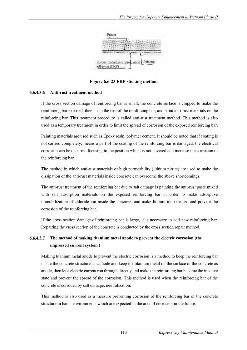
The Project for Capacity Enhancement in Vietnam Phase II
113 Expressway Maintenance Manual
Figure 6.6-23 FRP sticking method
Anti-rust treatment method
If the cross section damage of reinforcing bar is small, the concrete surface is chipped to make the
reinforcing bar exposed, then clean the rust of the reinforcing bar, and paint anti-rust materials on the
reinforcing bar. This treatment procedure is called anti-rust treatment method. This method is also
used as a temporary treatment in order to limit the spread of corrosion of the exposed reinforcing bar.
Painting materials are used such as Epoxy resin, polymer cement. It should be noted that if coating is
not carried completely, means a part of the coating of the reinforcing bar is damaged, the electrical
corrosion can be occurred focusing to the position which is not covered and increase the corrosion of
the reinforcing bar.
The method in which anti-rust materials of high permeability (lithium nitrite) are used to make the
dissipation of the anti-rust materials inside concrete can overcome the above shortcomings.
The anti-rust treatment of the reinforcing bar due to salt damage is painting the anti-rust paste mixed
with salt adsorption materials on the exposed reinforcing bar in order to make adsorptive
immobilization of chloride ion inside the concrete, and make lithium ion released and prevent the
corrosion of the reinforcing bar.
If the cross section damage of reinforcing bar is large, it is necessary to add new reinforcing bar.
Repairing the cross section of the concrete is conducted by the cross section repair method.
The method of making titanium metal anode to prevent the electric corrosion (the
impressed current system )
Making titanium metal anode to prevent the electric corrosion is a method to keep the reinforcing bar
inside the concrete structure as cathode and keep the titanium metal on the surface of the concrete as
anode, then let a electric current run through directly and make the reinforcing bar become the inactive
state and prevent the spread of the corrosion. This method is used when the reinforcing bar of the
concrete is corroded by salt damage, neutralization.
This method is also used as a measure preventing corrosion of the reinforcing bar of the concrete
structure in harsh environments which are expected in the area of corrosion in the future.

The Project for Capacity Enhancement in Vietnam Phase II
114 Expressway Maintenance Manual
Figure 6.6-24 The impressed current system to prevent the electric corrosion
Due to the high cost and large scale construction, this method is only used in the special case of
corrosion. In anti-corrosion methods by changing the titanium metal anode, depending on the maker,
there are different methods as titanium mesh method, conductive coating material method, titanium
grid method, In Internal closet anode method, it is necessary to choose the method suitable for the spot
situation.
In the electric anti-corrosion method, it is necessary to conduct regular maintenance checks to confirm
the system is operating in an effective manner or not.
- Normal check: every two months (confirm amperage, electrometry)
- Periodical check: one per year, with four times for the first year to confirm the integrity of the
entire anti-corrosion network.
- Exact check: one in five years
The electric anti-corrosion methods by changing the zinc anode (the anode current
system)
These are methods to keep the reinforcing bar inside the concrete structure as cathode and keep the
zinc on the surface of the concrete as anode, then let electric current run through directly and make
the reinforcing bar become the inactive state and prevent the spread of the corrosion.
The methods are used when the reinforcing bar of the concrete is corroded by salt damage,
neutralization,
The methods are also used as a measure preventing corrosion of the reinforcing bar of the concrete
structure in harsh environments which are expected in the area of corrosion in the future.

The Project for Capacity Enhancement in Vietnam Phase II
115 Expressway Maintenance Manual
Figure 6.6-25 Conception of the anode current system
Due to the high cost and large scale construction, these methods are only used in the special case of
corrosion.
The methods consist of:
(1) Zinc sheet method
Use anchor bolts to fix the zinc anti-corrosion sheet made from zinc sheet; special back fill and
protective cover on the concrete surface and install monitoring equipment.
(2) Zinc injection method
Spray tiny zinc particles in molten state which is heated, accelerated by spraying gun on the
concrete surface, form a zinc-spray film on the concrete surface and joint electrically with the
reinforcing bar inside the concrete.
The electric anti-corrosion method by changing the zinc anode does not need a power source but
because zinc will corrode by a potential difference, so if using zinc of thickness of 1mm, the effect
period is about 15 years.
Electro chemic desalination method
This is the method of housing external electrode temporarily and let an electric current run directly
through the reinforcing bars inside the concrete and extract salt out the concrete.
The desalination method is used when the salt concentration in the reinforcing bar reaches over the
rusting limit (1.22.0 kg/m3) or if does not interfere with, the salt concentration will predicted to
increase. This method is effective in the case when the method of removing the concrete aging due to
salt damage and covering the cross section does not match.

The Project for Capacity Enhancement in Vietnam Phase II
116 Expressway Maintenance Manual
Figure 6.6-26 Conception of electro chemic desalination method
This method cannot be applied in the following environment:
- The places where cannot set up scaffolding
- In the case of on-going implementation of measures to protect the insulation surface on the
concrete surface.
- In the case where the concrete surface is wet
- In the case where conductors such as bolts are being exposed.
In the desalting method, it is necessary to let an electric current with power density of 1A per 1m2 of
the concrete surface area run continuously about 8 weeks.
Electro chemic re-alkali method
This is the method of housing external electrode temporarily and let electric current run directly
through the reinforcing bars inside the concrete and make alkaline solution in temporary materials
penetrate compulsorily into the concrete and re-alkali. This method is used in cases which
neutralization is spreading to the reinforcing bars position steel core, or if does not interfere with, the
neutralization is predicted to spread and make corrosion of the reinforcing bars.
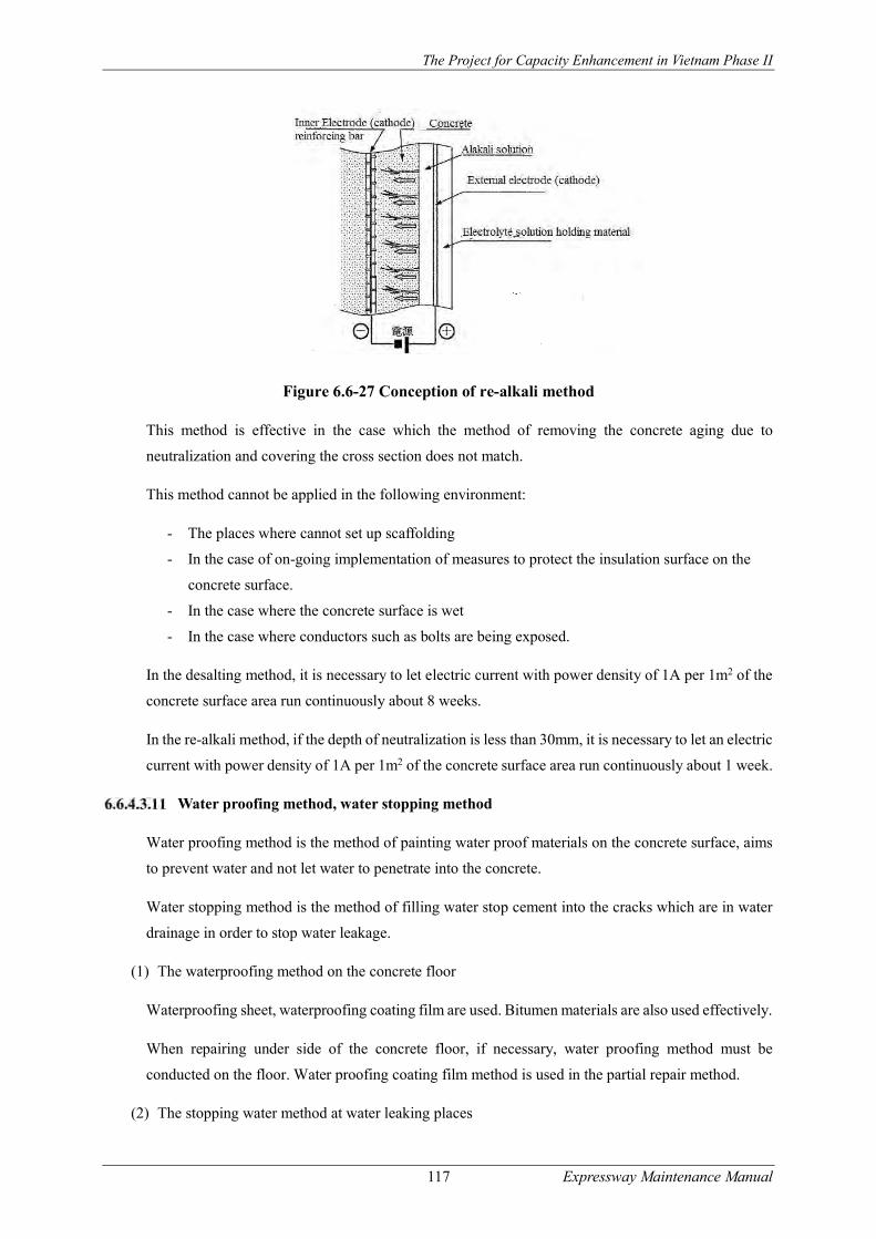
The Project for Capacity Enhancement in Vietnam Phase II
117 Expressway Maintenance Manual
Figure 6.6-27 Conception of re-alkali method
This method is effective in the case which the method of removing the concrete aging due to
neutralization and covering the cross section does not match.
This method cannot be applied in the following environment:
- The places where cannot set up scaffolding
- In the case of on-going implementation of measures to protect the insulation surface on the
concrete surface.
- In the case where the concrete surface is wet
- In the case where conductors such as bolts are being exposed.
In the desalting method, it is necessary to let electric current with power density of 1A per 1m2 of the
concrete surface area run continuously about 8 weeks.
In the re-alkali method, if the depth of neutralization is less than 30mm, it is necessary to let an electric
current with power density of 1A per 1m2 of the concrete surface area run continuously about 1 week.
Water proofing method, water stopping method
Water proofing method is the method of painting water proof materials on the concrete surface, aims
to prevent water and not let water to penetrate into the concrete.
Water stopping method is the method of filling water stop cement into the cracks which are in water
drainage in order to stop water leakage.
(1) The waterproofing method on the concrete floor
Waterproofing sheet, waterproofing coating film are used. Bitumen materials are also used effectively.
When repairing under side of the concrete floor, if necessary, water proofing method must be
conducted on the floor. Water proofing coating film method is used in the partial repair method.
(2) The stopping water method at water leaking places

The Project for Capacity Enhancement in Vietnam Phase II
118 Expressway Maintenance Manual
In water stopping materials, there are cement system water stopping materials, cement system osmosis
water proofing materials, urethane resin system water stopping materials.
The method to replacing the entire materials
This method is applied in cases such as damage on a large scale and the case in which concrete quality
is poor so construction is particularly bad, and it is difficult to conduct repairing and reinforcing, and
the case in which the result of repairing and reinforcing cannot be expected. Meanwhile, we will
replace with the entire new concrete of the same shape with the present condition.
In the construction process, it is necessary to stop all the traffic or proceed with traffic lane regulation,
only permit a part of vehicles go through. Until the casted concrete become harden, it is necessary to
pay attention not to give excessive vibration and collision, transformation, and to consider the speed
control of the traffic vehicle.
Bridge bearing repair
Introduction
Damage of the bridge bearing is caused by a lateral move and the subsidence of the substructure, and
the influence of other parts (materials) including the slant. In these cases, in combination with repairing
the bridge bearing, it is necessary to repair and reinforce the other parts (materials).
(1) Typical methods of bridge bearing repair
- The partial repair method
- The method of replacing the entire materials:
Replacing with the same shape,
Replacing with different shape
- The method of filling more materials
Anti-rust method: the painting repair method,
Method of injecting zinc
(2) When exchanging the bridge bearing, it is necessary to conduct the jack up. So it is necessary to
consider the reinforcement of the main girder, the cross girder and the reinforcement of widening
the abutment and the bridge pier.
(3) The criteria of cause of damage and repair method are shown in Table 6.6-21.
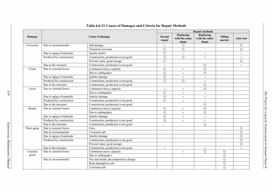
The Project for C
apacity Enhancem
ent in Vietnam P
hase II
119
E
xpressway M
aintenance Manual
Table 6.6-21 Causes of Damages and Criteria for Repair Methods
Damage Cause of damage
Repair methods
Partial repair
Replacing with the same
shape
Replacing with the other
shape
Filling mortar
Anti-rust
Corrosion Due to environmental Salt damage ○ ◎ ◎ Chemical corrosion ◎ ◎ ◎
Due to aging of materials Quality defect ◎ ○ ○ ○ Produced by construction Construction, production is not good ◎ ◎ ○ ○
Prevent water, good sewage ◎ ◎ Due to the structure Construction, production is not good ○ ◎ ○
Crack Due to external forces Continuous heavy capacity ◎ ○ ◎ Due to earthquakes ◎ ○ ◎
Due to aging of materials Quality damage ◎ ○ ○ Produced by construction Construction, production is not good ◎ ◎ ○ Due to the structure Construction, production is not good ◎
Loose Due to external forces Continuous heavy capacity ○ ○ ◎ Due to earthquakes ◎ ○ ○
Due to aging of materials Quality damage ◎ ○ ○ Produced by construction Construction, production is not good ◎ ○ ○ Due to the structure Construction, production is not good ◎
Breaks Due to external forces Continuous heavy capacity ◎ ○ ◎ Due to earthquakes ◎ ○ ◎
Due to aging of materials Quality damage ◎ ○ ○ Produced by construction Construction, production is not good ◎ ○ ○ Due to the structure Construction, production is not good ◎
Paint aging Due to external forces Fires ◎ Due to environmental Corrosion salt ◎ Due to aging of materials Quality damage ◎ Produced by construction Construction, production is not good ◎
Prevent water, good sewage ◎ Due to the structure Construction, production is not good ○ ○ ○
Cracked grout
Due to external forces Continuous heavy capacity ○ ◎ ◎ Due to earthquakes ◎
Due to environmental Dry and shrink, the temperature change ◎ Been damaged in salt ◎ Corrosion salt ◎

The Project for C
apacity Enhancem
ent in Vietnam P
hase II
120
E
xpressway M
aintenance Manual
Damage Cause of damage
Repair methods
Partial repair
Replacing with the same
shape
Replacing with the other
shape
Filling mortar
Anti-rust
Due to aging of materials Be neutral ◎ Quality damage ◎
Produced by construction Construction, production is not good ◎ Prevent water, good sewage ◎
Due to the structure Construction, production is not good ◎ ○ There is a
strange noise
Due to external forces Continuous heavy capacity ◎ ○ ◎ Due to earthquakes ◎ ○ ◎ Due to land pressure, the subsidence ◎ ◎ ◎ Washing by digging, corrosion ◎ ◎ ◎
Due to environmental Dry and shrink, the temperature change ◎ ○ Due to aging of materials Quality damage ◎ ○ Produced by construction Construction, production is not good ◎ ○ Due to the structure Construction, production is not good ◎
Moving Due to external forces Continuous heavy capacity ◎ ○ ◎ Due to earthquakes ◎ ○ ◎ Due to land pressure, the subsidence ◎ ◎ ◎ Washing by digging, corrosion ◎ ◎ ◎
Due to environmental Dry and shrink, the temperature change ◎ ○ Produced by construction Construction, production is not good ◎ ○ Due to the structure Construction, production is not good ◎
◎: Extremely effective, ○: Effective
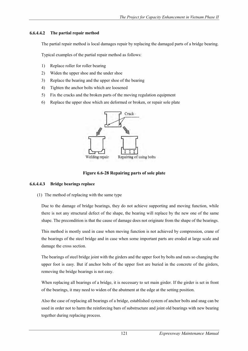
The Project for Capacity Enhancement in Vietnam Phase II
121 Expressway Maintenance Manual
The partial repair method
The partial repair method is local damages repair by replacing the damaged parts of a bridge bearing.
Typical examples of the partial repair method as follows:
1) Replace roller for roller bearing
2) Widen the upper shoe and the under shoe
3) Replace the bearing and the upper shoe of the bearing
4) Tighten the anchor bolts which are loosened
5) Fix the cracks and the broken parts of the moving regulation equipment
6) Replace the upper shoe which are deformed or broken, or repair sole plate
Figure 6.6-28 Repairing parts of sole plate
Bridge bearings replace
(1) The method of replacing with the same type
Due to the damage of bridge bearings, they do not achieve supporting and moving function, while
there is not any structural defect of the shape, the bearing will replace by the new one of the same
shape. The precondition is that the cause of damage does not originate from the shape of the bearings.
This method is mostly used in case when moving function is not achieved by compression, crane of
the bearings of the steel bridge and in case when some important parts are eroded at large scale and
damage the cross section.
The bearings of steel bridge joint with the girders and the upper foot by bolts and nuts so changing the
upper foot is easy. But if anchor bolts of the upper foot are buried in the concrete of the girders,
removing the bridge bearings is not easy.
When replacing all bearings of a bridge, it is necessary to set main girder. If the girder is set in front
of the bearings, it may need to widen of the abutment at the edge at the setting position.
Also the case of replacing all bearings of a bridge, established system of anchor bolts and snag can be
used in order not to harm the reinforcing bars of substructure and joint old bearings with new bearing
together during replacing process.

The Project for Capacity Enhancement in Vietnam Phase II
122 Expressway Maintenance Manual
(2) The method of replacing with other type
Due to the damage of bridge bearings, they do not achieve supporting function and moving function,
replacing new bearings with specific type can be proposed. A typical example is that the roller of a
roller bearing is damaged; the roller bearing can be replaced by new bearing.
When replacing all bearings of bridge, it is necessary to set a main girder. If the girder is set in front
of the bearing, it may need to widen the edge of the abutment at the setting position.
Methods of filling more materials
(1) The method of filling mortar
This method includes setting a girder and conducts a jack-up, snag the damaged mortar, and fill no
shrinkage mortar upon.
Mortar damage can be caused from corrosion of steel material which is used to control height and
shape of bearing. The corroded steel must be removed and replaced by new one, and then new mortar
is filled back in.
(2) The painting repair method
After cleaning the rusted part, bearing surface is painted to prevent corrosion. The condition is that it
must ensure the space to be able to carry out cleaning and painting. If the movable function is lost by
corrosion, it is necessary to inject lubricant into.
(3) The method of injecting zinc
The bearings are cleaned completely by brush, and a spraying film of the alloy of zinc and zinc
aluminum is applied on the surface of the bearings. If the spraying film of the alloy of zinc and zinc
aluminum then can be coated by epoxy resin of permeability, the anti-rust effect will be higher than
normal but cost is high.
This method is effective for corrosion caused by water leakage from flexible equipment and the
accumulation of dust after years. If the movable function of bearings is lost by corrosion, it is necessary
to inject lubricant into.
Repair expansion joints
Overview
Damage of expansion joints is caused by a lateral move and the subsidence of the substructure, and
the influence of other parts (materials) including the sealant. In these cases, in combination with
repairing the flexible equipment, it is necessary to repair and reinforce the other parts (materials).
The typical methods of expansion joints repair are as follow:
- The partial repair method
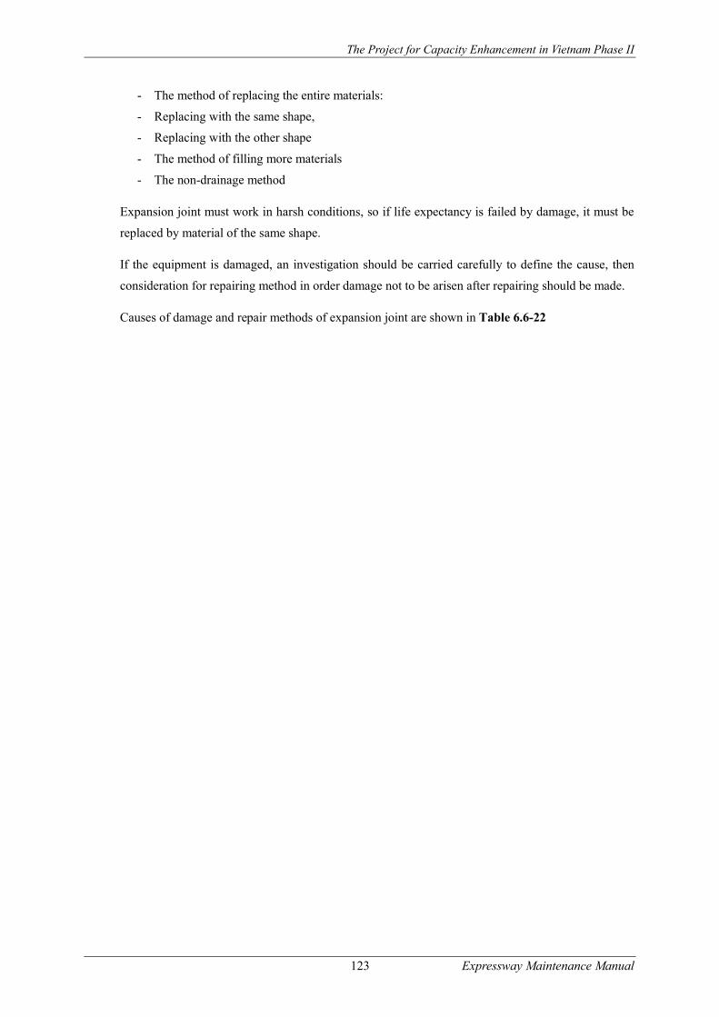
The Project for Capacity Enhancement in Vietnam Phase II
123 Expressway Maintenance Manual
- The method of replacing the entire materials:
- Replacing with the same shape,
- Replacing with the other shape
- The method of filling more materials
- The non-drainage method
Expansion joint must work in harsh conditions, so if life expectancy is failed by damage, it must be
replaced by material of the same shape.
If the equipment is damaged, an investigation should be carried carefully to define the cause, then
consideration for repairing method in order damage not to be arisen after repairing should be made.
Causes of damage and repair methods of expansion joint are shown in Table 6.6-22
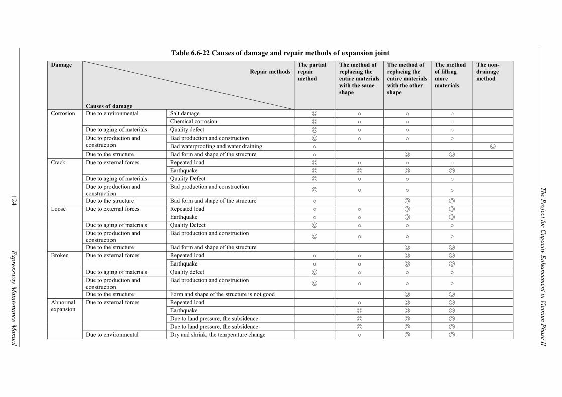
The Project for C
apacity Enhancem
ent in Vietnam P
hase II
124 E
xpressway M
aintenance Manual
Table 6.6-22 Causes of damage and repair methods of expansion joint
Damage Repair methods
Causes of damage
The partial repair method
The method of replacing the entire materials with the same shape
The method of replacing the entire materials with the other shape
The method of filling more materials
The non-drainage method
Corrosion Due to environmental Salt damage ◎ ○ ○ ○ Chemical corrosion ◎ ○ ○ ○
Due to aging of materials Quality defect ◎ ○ ○ ○ Due to production and construction
Bad production and construction ◎ ○ ○ ○ Bad waterproofing and water draining ○ ◎
Due to the structure Bad form and shape of the structure ○ ◎ ◎ Crack Due to external forces Repeated load ◎ ○ ○ ○
Earthquake ◎ ◎ ◎ ◎ Due to aging of materials Quality Defect ◎ ○ ○ ○ Due to production and construction
Bad production and construction ◎ ○ ○ ○
Due to the structure Bad form and shape of the structure ○ ◎ ◎ Loose Due to external forces Repeated load ○ ○ ◎ ◎
Earthquake ○ ○ ◎ ◎ Due to aging of materials Quality Defect ◎ ○ ○ ○ Due to production and construction
Bad production and construction ◎ ○ ○ ○
Due to the structure Bad form and shape of the structure ◎ ◎ Broken Due to external forces Repeated load ○ ○ ◎ ◎
Earthquake ○ ○ ◎ ◎ Due to aging of materials Quality defect ◎ ○ ○ ○ Due to production and construction
Bad production and construction ◎ ○ ○ ○
Due to the structure Form and shape of the structure is not good ◎ ◎ Abnormal expansion
Due to external forces Repeated load ○ ◎ ◎ Earthquake ◎ ◎ ◎ Due to land pressure, the subsidence ◎ ◎ ◎ Due to land pressure, the subsidence ◎ ◎ ◎
Due to environmental Dry and shrink, the temperature change ○ ◎ ◎
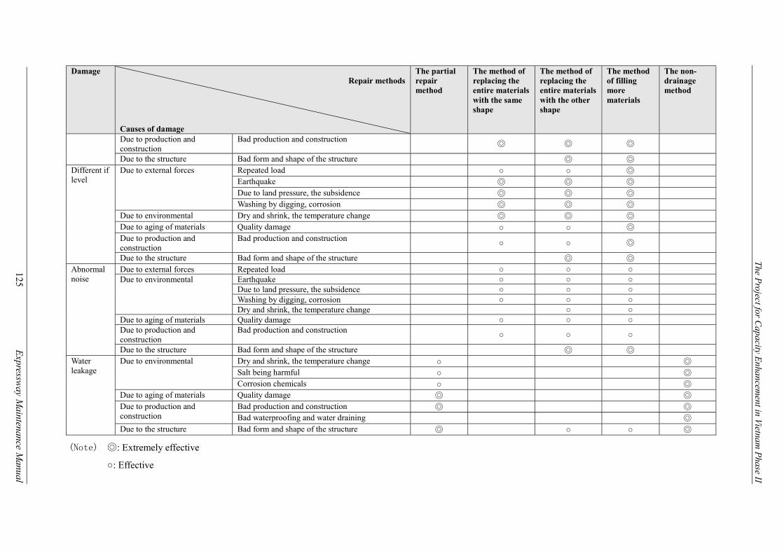
The Project for C
apacity Enhancem
ent in Vietnam P
hase II
125 E
xpressway M
aintenance Manual
Damage Repair methods
Causes of damage
The partial repair method
The method of replacing the entire materials with the same shape
The method of replacing the entire materials with the other shape
The method of filling more materials
The non-drainage method
Due to production and construction
Bad production and construction ◎ ◎ ◎
Due to the structure Bad form and shape of the structure ◎ ◎ Different if level
Due to external forces Repeated load ○ ○ ◎ Earthquake ◎ ◎ ◎ Due to land pressure, the subsidence ◎ ◎ ◎ Washing by digging, corrosion ◎ ◎ ◎
Due to environmental Dry and shrink, the temperature change ◎ ◎ ◎ Due to aging of materials Quality damage ○ ○ ◎ Due to production and construction
Bad production and construction ○ ○ ◎
Due to the structure Bad form and shape of the structure ◎ ◎ Abnormal noise
Due to external forces Repeated load ○ ○ ○ Due to environmental Earthquake ○ ○ ○
Due to land pressure, the subsidence ○ ○ ○ Washing by digging, corrosion ○ ○ ○ Dry and shrink, the temperature change ○ ○
Due to aging of materials Quality damage ○ ○ ○ Due to production and construction
Bad production and construction ○ ○ ○
Due to the structure Bad form and shape of the structure ◎ ◎ Water leakage
Due to environmental Dry and shrink, the temperature change ○ ◎ Salt being harmful ○ ◎ Corrosion chemicals ○ ◎
Due to aging of materials Quality damage ◎ ◎ Due to production and construction
Bad production and construction ◎ ◎ Bad waterproofing and water draining ◎
Due to the structure Bad form and shape of the structure ◎ ○ ○ ◎
(Note) ◎: Extremely effective
○: Effective

The Project for Capacity Enhancement in Road Maintenance in Vietnam Phase II
126 Expressway Maintenance Manual
The partial repair method
If the expansion joint is damaged partially, the damaged part should be repaired and replaced.
Typical examples of this method are as follows:
1) Replace the damaged bolts
2) Pour materials into the detached bolt hole
3) Replace gum of the steel joint which are detached
4) Repair cracks of the steel finger joint
Replacing the entire materials
(1) The method of replacing the entire materials with the same type
The damaged expansion joint when being unable to repair by the partial repair method, can be replaced
by new one. If there is not any problem with the form of joint before repairing, the replacement of new
joint is for the life of the joint, the damaged joint can be replaced by new joint with same form.
Before replacing the entire joint, it is necessary to check expansion gap and expansion quantity. If the
expansion gap is in the appropriate range which required expansion joint, the damaged joint can be
replaced by new one without any problems.
The expansion quantity should be calculated before repair considering to construction statement,
drying and shrinking properties of sealant material.
It is necessary to combine the method of replacing the entire materials with the method of filling more
materials.
(2) The method of replacing new materials with a new shape
If it is unable to repair by the partial repair method and keeping the shape as before repairing is not
suitable, method of replace the entire expansion joint with a new shape is recommended.
When replacing the entire equipment, it is necessary to check expansion gap and expansion quantity
before, and replace with new equipment of different shape which is suitable to the range of expansion
gap. The expansion quantity should be calculated before repair considering to construction statement,
drying and shrinking properties of sealant material.
When replacing with other shape, the matching gum joints will drop out easily so it is necessary to
replace with the gum joints of the underground laying system or the load bearing system.
If the expansion gap is too large in comparison with expansion quantity, we should consider for
repairing the edge of the floor. In addition, if expansion quantity is small, it is necessary to consider
changing to the underground laying system.

The Project for Capacity Enhancement in Road Maintenance in Vietnam Phase II
127 Expressway Maintenance Manual
It is necessary to combine the method of replacing the entire materials with the method of filling more
materials.
The method of filling more materials
For the method of filling more materials, it is necessary to fix expansion joint before pouring more
materials into them on two sides of expansion gap. In case of cracks and peeling of the filled materials
are visible, loose materials should be removed for clean joint then replaced by new materials.
The damage of expansion joint needs to be repaired soon in any case. The damage of filled parted if
being ignored will result to damage of fixing position of the expansion joint and widespread of damage
to the entire expansion joint.
The later filling materials are used can be resin concrete, resin mortar, concrete, mortar, etc. However,
super quick hardening concrete should be used for traffic opened early.
The non-drainage method
The steel finger joint of the old type have the form as a drainage gutter established under the joint but
due to the accumulation of earth and sand, water drainage is not completely and causes damage of the
substructure and the surrounding of the bearing.
The non-drainage method includes filling back up materials and elastic seal materials into the
expansion gap. The structure of this method has stainless gutter type and web type.
Figure 6.6-29 Non-drainage method
The backup materials are used as polyurethane and polyethylene, but recently urethane material of
high elasticity is mostly used. In addition, foaming gum can be set on top of elastic seal materials to
prevent the materials flying out. In the method of injecting elastic seal materials, it is necessary to
control traffic until the sealing material is compressed to 85% of completion.
Bridge cleaning
Except for special cases, the bridge itself virtually rarely cleaned but at the points where are next to
the truss bridge, in terms of structure, in the places of waste accumulation, they are easy to make the

The Project for Capacity Enhancement in Road Maintenance in Vietnam Phase II
128 Expressway Maintenance Manual
bridge rusty so periodical inspection and cleaning is necessary. Also, in expanded or narrow places,
near the supporting places, soil and sand can easily accumulate to affect the function of the bridge and
it is considered as the cause of bridge damage so it is necessary to have bridge cleaned while periodic
inspection.
Besides, if the sewage system blocked, in case of high suspension bridges then at the places where are
under a girder bridge, it will easily arise problems. If the road is flooded, it would obstruct the traffic.
To avoid this situation, it is necessary to check the sewage system (if any) and to carry out cleaning.
Data Registration of Maintenance and Repair History
Record of repairing in principle is keeping the checking time, the detailed investigation, and the
operation time of the structure.
The record should present how repairing works have been conducted according result of checking,
surveying, etc. for the bridge. It also includes details of repairing work, such as repairing parts,
repairing method and the person in charge of repairing, etc.
The standard contents should be recorded during repair implementation are shown in Table 6.6-23.
Table 6.6-23 Typical contents to be recorded during repair implementation
Person in charge of repairing Name of the repairing company, name of the person in charge of the repair (repair work manager)
Date of repairing Repairing time, starting and completing date Repair purposes Type of damage, the detailed investigation Repairing location Repairing locations, name of the used materials, the scope of repair
work Repair methods Repair methods, the used main material Repairing results Report of the repairing results Evaluation results after repairing Number of years that the repairing is effective (the warranty period
of repairing that the manager required)* Evaluation results on the necessity of repairing
Note: If the repair technology is new technology used in recent years, however, it should be clear in record whether it is able to verify the durability of the repair methods or not.
Record of repairing works in addition should include information of repaired parts condition by time.
It is because of the repaired parts will be aging and need to be repaired again, so it is necessary to
check the repaired parts regularly and record durability and the problem of the repair methods in order
to store information and data.
Road Tunnel Maintenance Management
Introduction
It is necessary to evaluate the abnormal states of tunnels by the investigation and estimation of the
causes. Depending on the state of change, it is needed to discuss the most appropriate method to be

The Project for Capacity Enhancement in Road Maintenance in Vietnam Phase II
129 Expressway Maintenance Manual
able to restore the functionality and endurance of the tunnel’s structures that were weakened.
According to actual tunnel condition based on the inspection and investigation results, considering to
maintenance policy, the economic decisions of the scope and scale of the project that must meet the
requirements of the policy.
There can have two types of project scale for tunnel maintenance. The first is repairing that can
promote the normal function and parts of the tunnel after arising abnormal status. The second is
extreme large scale which can affect to components of the tunnel and be applied in the case of
abnormal state of the tunnel has been going on.
Typical Damages Observed
Tunnel damage types
The most significant problem in constructed tunnels is groundwater intrusion. The presence of water
in a tunnel, especially if uncontrolled and excessive, accelerates corrosion and deterioration of the
tunnel liner. Other popular defects of tunnel are cracks, damages of segmental liners, corrosion of
steels or cast iron components, concrete or masonry elements movements or degradation which create
gaps at backfill. All these defects relates directly to problem of groundwater intrusion.
Groundwater intrusion is phenomenon of water appearance on roof or ceiling of the tunnel through
cracks. Each site of groundwater intrusion has its own particular environmental and physical properties
which impact to treatment selection. They are pH, hardness, chemical composition, turbidity of the
groundwater entering the tunnel, which contribute to the ability of the chemical or particle grouts to
effectively seal the leaking defect, and physical conditions that created the defect, movement of the
crack or joint, the potential for freezing and the amount of water inflow all are site specific constraints
for the selection of the repair material.
The selection of the proper grout to seal a tunnel liner is dependent on the degree of leakage into the
tunnel from the defect. Typically the tunnel defects that cause leakage are construction joints liner
gaskets, and cracks that are the full depth of the liner. Standardized terms have been developed to
describe the inflow of water. The degree of water inflow is in Table 6.7-1.
Table 6.7-1 Descriptions of tunnel leakage
Item Symbol Description Moist M Discoloration of the surface of the lining, moist to touch Past Moisture PM Area showing indications of previous wetness, calcification Glistening Surface GS Visible movement of a film of water across a surface Flowing F Continuous flow of water from a defect; requires volume measurement Dry D Structural defect illustrates no signs of moisture
Monitoring and causes of damage
Monitoring means observing carefully main points discovered through the investigation process of
standards, the process of thorough investigation and policy construction positions for unusual points.

The Project for Capacity Enhancement in Road Maintenance in Vietnam Phase II
130 Expressway Maintenance Manual
For the contents of observation, in case of following the causes of abnormal changes we have to make
daily checks. Confirming effectiveness of changes and policy, construction method must have the
same content and level of investigation.
Treatment for tunnel damages should be made after knowing exactly the cause of the abnormality and
based on assessment of the effectiveness, feasibility, safety, and economic as well as construction time
considering maintenance policy.
These measures are not merely adding materials, reinforcing and improving the degradation positions
of the tunnel, but it also includes items and measures to strengthen the control and supervision of
tunnel’s degradation as well as controlling and supervising traffic under tunnel’s condition.
One of the focal points of these policies is that if it removes the management of emergency when there
is unusual state, it must understand the causes of these abnormal states. If in terms of research,
depending on each cause of those unusual states that we can see phenomenon of the different change
of state. Therefore, for guessing reasons of degradation, together with reading the special causes, we
also need to conduct generally based on materials related to the design and construction of the tunnel,
cadastral status to verify latitude longitude location of the situation that arises abnormal changes. The
causes for state change of the tunnel will be classified as following:
- Soft soil foundation (including collapse due to cracks)
- Pressure of rocks and earth deviating on one side
- Land-slip
- Soil pressure with expansion
- Lack of capacity to support
- Water pressure
- Pressure of frozen soil
- Degraded arterial and material
- Water leak
- Back type face to be empty
- Not enough thickness
- No invert arch
Treatment selection
Above is the list of the causes, however, the causes occur only by a reason is very few, almost it usually
happens by a few overlap reasons and cases such as the nature of the construction materials at each
time, the design is error and empty at back type face or improper construction also is the cause. So to
choose a method of the policy, we need to calculate carefully the items as specified in the Table 5.13.1,
and even independent and combination construction method, we also need to study carefully. In
addition, when constructing, we also need to focus on the calculation to the regulations on traffic,
safety measures as well as the time when carrying out the project.

The Project for Capacity Enhancement in Road Maintenance in Vietnam Phase II
131 Expressway Maintenance Manual
Inspection of Road Tunnel
Focus Point of Inspection
(1) The inner lining concrete is deteriorated by chemical reaction working between lining concrete and
chemical components in the water. Damages appear on the concrete in the forms of cracks, peeling,
creeping, carbonation, water leakage and free lime.
(2) Concrete cracks on the inner lining concrete are caused by tensile stress working on the Tunnel
Lining, which is a deviated pressure generated by land slide occurring nearby Tunnel or changes
in pressure of natural ground behind the Tunnel Lining. This deviated pressure is a main cause of
tunnel damage, so that it is necessary to check carefully and conduct detailed inspection when it is
found.
(3) The water leakage from concrete lining is often caused by the voids in the lining
concrete, causing deviated pressure on the Tunnel Lining. The water leakage leads to
the damages not only to the Tunnel body, but to the pavement, creating slippery
driving conditions in the tunnel.
(4) Poor construction quality, including improper repair works on the concrete lining,
insufficient concrete pouring into arch crown and improper concrete joint construction,
often leads to cracks, peeling, corner dropping, and water leakage due to aging and
earthquakes.
(5) Tunnel Portals are in general constructed on the ground which has sufficient bearing
capacity. However, if they are constructed on the steep slope in the mountainous area,
uneven settlement of portal facility often occur due to insufficient bearing capacity of
the ground, thereby causes transverse cracks on the portals and gaps at the
construction joints. With this, it is necessary to inspect surrounding areas of the
Tunnel Portal.
(6) The damages of Tunnel Interior Decoration Board are often caused by water leakage
or the material deformation given by vehicle accident often appears in the form of
corrosion on the fixing bolts.
(7) Damages on the Drainage Systems in the Tunnel including deformation or break of
the Drainage System are often caused by the deviated stresses working on the
concrete lining.
(8) Damages on the pavement in the Tunnel including cracks, depressions or swelling are
often caused by external stresses originated from the deformation of Tunnel Portal
and lining concrete.

The Project for Capacity Enhancement in Road Maintenance in Vietnam Phase II
132 Expressway Maintenance Manual
Inspection Points
Road facility inspection for Tunnel facilities shall be implemented on the inspection points shown in
Table 6.7-2 for Tunnel Concrete Lining, Table 6.7-3 for Tunnel Portal and Table 6.7-4 for Tunnel
Interior Decoration Board. Also, Figure 6.7-1 illustrates inspection points on the Tunnel Lining and
Figure 6.7-2 inspection points on the interior facilities.
Table 6.7-2 Inspection Points (Concrete Lining)
Structure Position Member Sort of damage Initial Inspection
Daily Inspection
Periodic Inspection
Detailed Inspection
Tunnel Concrete lining
Cracks/ corner drop X X X
As required by Routine or Periodic Inspection
Peel X X X Joint gap X X X Leakage/ free lime
X X X
Spalling, Void X X X
(Note) X15: To inspect 15~20 years after from opening to traffic.
Table 6.7-3 Inspection Points (Portal)
Structure Position Member Sort of Damage
Initial Inspection
Routine Inspection
Periodic Inspection
Detailed Inspection
Tunnel Portal /entrance
Cracks/ corner drop
X X X
As required by Routine or Periodic Inspection
Peeling X X X Rebar exposure
X X X
Settlement/ movement / tilt
X X X
Joint gap X X X Scouring X X X Drain/ spring water
X X X
(Note) X: Inspection items, but not limited.
Table 6.7-4 Inspection Points (Interior Decoration Board and Others)
Structure Position Member Sort of Damage
Initial Inspection
Routine Inspection
Periodic Inspection
Detailed Inspection
Tunnel Inner decoration board
Body damage (plate type)
-------- X X
As required by Routine or Periodic Inspection
Body damage (tile type)
-------- X X
Accessory damage
-------- X X
Drain system
Facility damage
-------- X X
Debris and soil piling
-------- X X
(Note) X: Inspection items, but not limited.
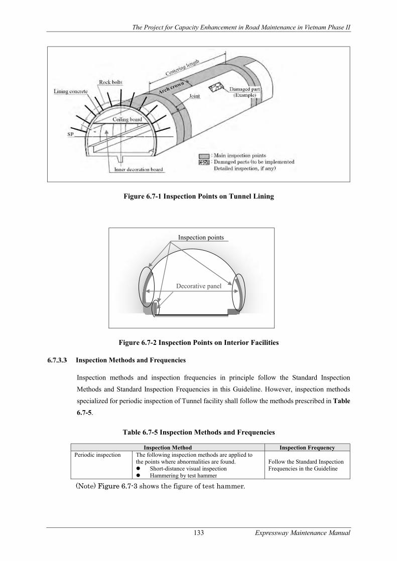
The Project for Capacity Enhancement in Road Maintenance in Vietnam Phase II
133 Expressway Maintenance Manual
Figure 6.7-1 Inspection Points on Tunnel Lining
Figure 6.7-2 Inspection Points on Interior Facilities
Inspection Methods and Frequencies
Inspection methods and inspection frequencies in principle follow the Standard Inspection
Methods and Standard Inspection Frequencies in this Guideline. However, inspection methods
specialized for periodic inspection of Tunnel facility shall follow the methods prescribed in Table
6.7-5.
Table 6.7-5 Inspection Methods and Frequencies
Inspection Method Inspection Frequency Periodic inspection The following inspection methods are applied to
the points where abnormalities are found. Short-distance visual inspection Hammering by test hammer
Follow the Standard Inspection Frequencies in the Guideline
(Note) Figure 6.7-3 shows the figure of test hammer.
Inspection points
Decorative panel

The Project for Capacity Enhancement in Road Maintenance in Vietnam Phase II
134 Expressway Maintenance Manual
Figure 6.7-3 Test Hammer
Evaluation of Inspection Results
(1) Evaluation of the results of routine inspection, periodic inspection and emergency inspection shall
be conducted, following relevant articles in this Guideline. Sample evaluation criteria for Tunnel
Lining are shown in ANNEX-F. Also, particular notes for the evaluation of some major damages
are described below;
(2) When cracks in high density are progressing rapidly or tensile cracks in wide gaps or shear cracks
appear on the concrete lining, the damage is rated as “D” in this Guideline.
(3) When large-scale concrete peeling or corner drops is found on the concrete lining, it leads to the fatal
damages given to the lining, so that the damage is rated as “D” in this Guideline.
(4) When above damages are expected to be caused by deviated pressure working on the Tunnel Lining,
detailed inspection shall be conducted immediately.
(5) When large-scale water leakage occurs from the Tunnel Lining, it may cause voids behind the
concrete lining, thereby causing harmful pressure on the Tunnel body. Rating “D” is applied to this
damage in this Guideline.
(6) When concrete cracks caused by uneven settlement or movement of Tunnel Portal is found in the
inspection, they will lead to fatal damages to the Tunnel Portal, the damage is rated as “D” in this
Guideline.
(7) When large scale damages including concrete cracks and gaps are found on the pavement and
drainage facilities inside Tunnel, which are caused by lateral or uplifting pressure, massive pressure
may be working on the Tunnel Lining. Rating “D” is applied to these damages in this Guideline.
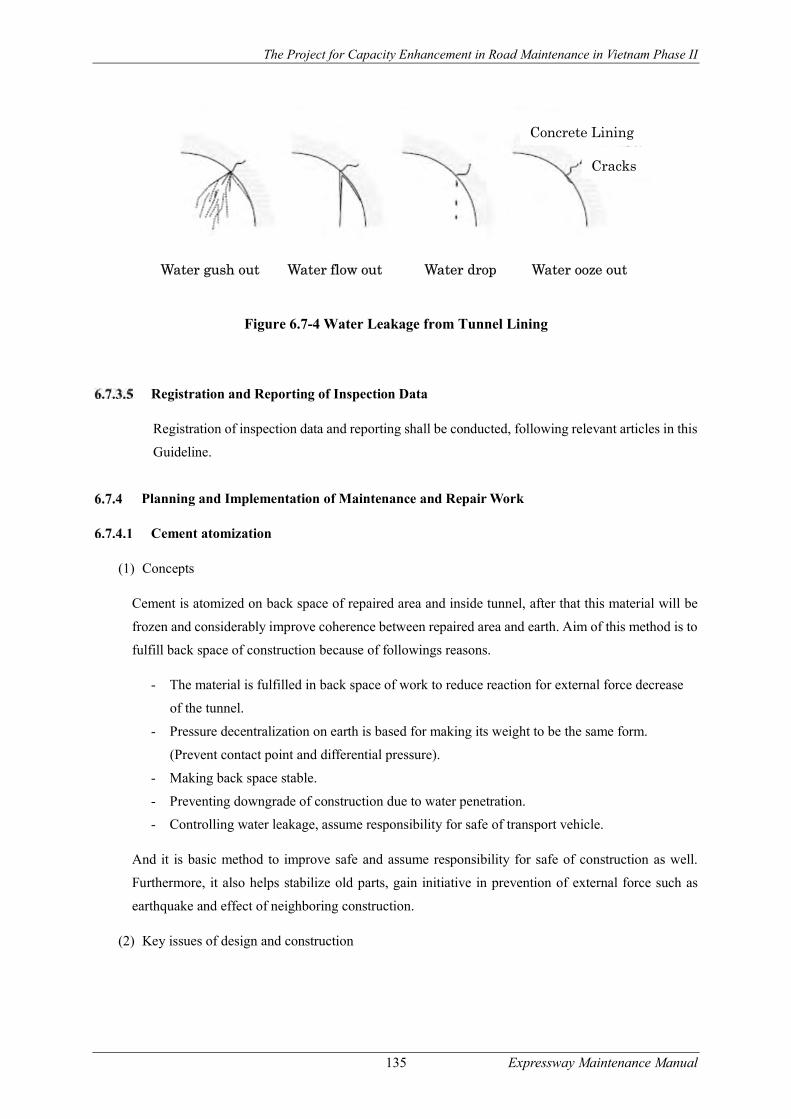
The Project for Capacity Enhancement in Road Maintenance in Vietnam Phase II
135 Expressway Maintenance Manual
Figure 6.7-4 Water Leakage from Tunnel Lining
Registration and Reporting of Inspection Data
Registration of inspection data and reporting shall be conducted, following relevant articles in this
Guideline.
Planning and Implementation of Maintenance and Repair Work
Cement atomization
(1) Concepts
Cement is atomized on back space of repaired area and inside tunnel, after that this material will be
frozen and considerably improve coherence between repaired area and earth. Aim of this method is to
fulfill back space of construction because of followings reasons.
- The material is fulfilled in back space of work to reduce reaction for external force decrease
of the tunnel.
- Pressure decentralization on earth is based for making its weight to be the same form.
(Prevent contact point and differential pressure).
- Making back space stable.
- Preventing downgrade of construction due to water penetration.
- Controlling water leakage, assume responsibility for safe of transport vehicle.
And it is basic method to improve safe and assume responsibility for safe of construction as well.
Furthermore, it also helps stabilize old parts, gain initiative in prevention of external force such as
earthquake and effect of neighboring construction.
(2) Key issues of design and construction
Water gush out Water flow out Water drop Water ooze out
Concrete Lining
Cracks

The Project for Capacity Enhancement in Road Maintenance in Vietnam Phase II
136 Expressway Maintenance Manual
Due to different atomized material, equipment and machines used in construction process and
atomization pressure, it should choose suitable method depending on actual conditions such as back
space, status of earth, leakage, construction condition.
Basically, material used for back atomizing is cement milk, cement mortar, air-cement milk or air-
cement sand grout. However, the method does not need so hard material such as concrete. So cement
mill or cement mortar can be replace with fly ash or bentonite, which helps reduce volume of cement
usage, its connection with AE active ingredient brings higher mobility.
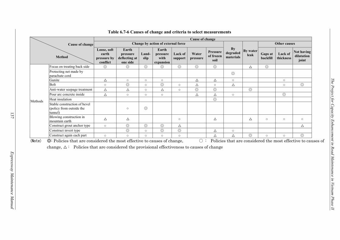
The Project for C
apacity Enhancem
ent in Road M
aintenance in Vietnam P
hase II
137
E
xpressway M
aintenance Manual
Table 6.7-6 Causes of change and criteria to select measurements
Cause of change
Method
Cause of change Change by action of external force
By degraded materials
By water leak
Other causes
Loose, soft earth
pressure by conflict
Earth pressure
deflecting at one side
Land-slip
Earth pressure
with expansion
Lack of support
Water pressure
Pressure of frozen
soil
Gaps at backfill
Lack of thickness
Not having dilatation
joint
Methods
Focus on treating back side ◎ ◎ ◎ ◎ ◎ ◎ ◎ △ ◎ Protecting net made by parachute cord
◎
Gunite △ ○ ○ ○ △ △ ○ ○ Bolt ○ ◎ ○ ◎ ○ △ ○ △ ○ ◎ Anti-water seepage treatment △ △ ○ △ ○ ◎ ◎ ◎ Pour arc concrete inside △ ○ ○ ○ △ △ ○ ◎ Heat insulation ◎ Stable construction of bevel (policy from outside the tunnel)
○ ◎
Blowing construction in mountain earth
△ △ ○ △ △ ○ ○ ○
Construct grout anchor type ○ ◎ ◎ ◎ △ △ Construct invert type ◎ ○ ◎ ◎ △ ○ Construct again each part ○ ○ ○ ○ ○ △ △ ◎ ○ ○ ◎
(Note) ◎: Policies that are considered the most effective to causes of change, ○ : Policies that are considered the most effective to causes of change, △ : Policies that are considered the provisional effectiveness to causes of change
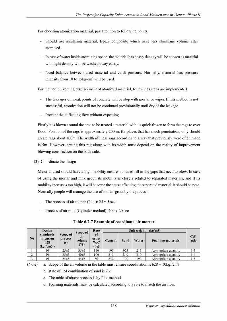
The Project for Capacity Enhancement in Road Maintenance in Vietnam Phase II
138 Expressway Maintenance Manual
For choosing atomization material, pay attention to following points.
- Should use insulating material, freeze composite which have less shrinkage volume after
atomized.
- In case of water inside atomizing space, the material has heavy density will be chosen as material
with light density will be washed away easily.
- Need balance between used material and earth pressure. Normally, material has pressure
intensity from 10 to 15kg/cm3 will be used.
For method preventing displacement of atomized material, followings steps are implemented.
- The leakages on weak points of concrete will be stop with mortar or wiper. If this method is not
successful, atomization will not be continued provisionally until dry of the leakage.
- Prevent the deflecting flow without expecting
Firstly it is blown around the area to be treated a material with its quick frozen to form the rags to over
flood. Position of the rags is approximately 200 m, for places that has much penetration, only should
create rags about 100m. The width of these rags according to a way that previously were often made
is 5m. However, setting this rag along with its width must depend on the reality of improvement
blowing construction on the back side.
(3) Coordinate the design
Material used should have a high mobility ensures it has to fill in the gaps that need to blow. In case
of using the mortar and milk grout, its mobility is closely related to separated materials, and if its
mobility increases too high, it will become the cause affecting the separated material, it should be note.
Normally people will manage the use of mortar grout by the process.
- The process of air mortar (P lot): 25 5 sec
- Process of air milk (Cylinder method): 200 20 sec
Table 6.7-7 Example of coordinate air mortar
No
Design standards intension
δ28 (kgf/cm3 )
Scope of process
(s)
Scope of air
volume (%)
Rate of
grout W/C (%)
Unit weight (kg/m3)
C:S ratio Cement Sand Water Foaming materials
1 10 25±5 35±5 110 195 975 215 Appropriate quantity 1:5 2 10 25±5 40±5 100 210 840 210 Appropriate quantity 1:4 3 10 25±5 45±5 80 240 720 192 Appropriate quantity 1:3
(Note) a. Scope of the air volume in the table must ensure coordination is δ28 = 10kgf/cm3
b. Rate of FM combination of sand is 2.2
c. The table of above process is by Plot method
d. Foaming materials must be calculated according to a rate to match the air flow.

The Project for Capacity Enhancement in Road Maintenance in Vietnam Phase II
139 Expressway Maintenance Manual
Table 6.7-8 An example of the combination of air milk
Design standards
intension δ28
(kgf/cm3)
Scope of
process
(mm)
Scope of
air volume
Rate of
grout W/C
(%)
Genetic
density
Unit weight (kg/m3)
Cement water Foaming
materials
10 200±20 65±5 66 0.58±0.05 350 231 17
(Note) a. Scope of the air volume in the table must ensure coordination is δ28 = 10kgf/cm3
b. Schedule process is by cylinder method
Table 6.7-9 Example of coordinating grout stopper
Liquid A (5001) kg Liquid B (5001)kg Quick frozen
substance Substance makes
slow Water Normal cement Water
100 0.3 465 300 403
Characteristics of blowing material are quick frozen substance according to a kind of cement are:
- The soft soils locate between the clay and sand, clay, and can be blown in as the circuit format.
- There is feature of gallate gel in a short time
- When combined with grout will have the high-strength.
Especially when blowing combination into renovation construction at the backside, where has the high
water permeability, after confirming result of test generally expect the following items.
- Dissociated materials (separated) in low construction process.
- After blowing, the stability in the treated region is enhanced.
- Volume changes a little.
(4) The construction procedure
The blowing procedure on backside will be sequential as following steps
Hole drill
Hole drill in concrete part of construction (of tunnel) on mark of
central hole drill
Install blowing equipment
After drilling, install blowing pipe into drilling hole
Grout
Blowing grout into hole by pump using pressure blowing forms
Change to another blowing point Confirm blew volume through access hole, after blowing necessary material volume, change to another point
- Hole drill and install the blowing equipment
Because of the blowing volume and level of effectiveness are different by blowing pipes are
arranged at positions separated according to line, so when constructing must grasp the state of
spaces that need to the construct of work. Normally the spaces of the building are near the arched

The Project for Capacity Enhancement in Road Maintenance in Vietnam Phase II
140 Expressway Maintenance Manual
roof of the tunnel, so when want to blow in an amount such that the left and right side are the same,
it will design blowing hole in the middle of the arches concrete. It is the most optimal method.
However, when calculating to traffic vehicle in the tunnel, if a tunnel is used for many lanes, it
often encounters problems such as the difficulty of the hole drill, connecting, the dismantling of
the tube used in the blowing process, the distribution of materials during construction, access to
the main routes so it is also divided into two above and below lines to make construction. The
blowing holes, after calculating and considering the amount of space and materials to blow, they
will set up the tunnel into two above and below lines about from 0.5 to 1 m as shown in Figure
6.7-5 and Figure 6.7-6. The designed holes are according to the actual damage conditions and
should be stated before construction. They have the same distance as the blowing hole drilled on
the arched roof of the tunnel.
Figure 6.7-5 Illustration of blowing pipes arrangement
Figure 6.7-6 Illustration of blowing pipe installation
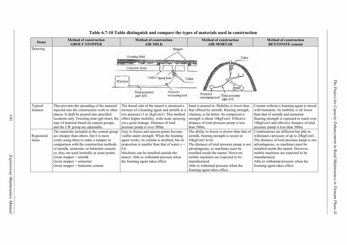
141
E
xpressway M
aintenance Manual
The Project for C
apacity Enhancem
ent in Road M
aintenance in Vietnam P
hase II
Table 6.7-10 Table distinguish and compare the types of materials used in construction
Items Method of construction
GROUT STOPPER Method of construction
AIR MILK Method of construction
AIR MORTAR Method of construction BENTONITE cement
Drawing
Typical features
This prevents the spreading of the material injected into the construction work to other places. It shall be poured into specified locations only. Freezing time (gel time), the type of material based on cement groups, and the LW group are adjustable.
The dorsal side of the tunnel is atomized a mixture of a foaming agent and airmilk at a low pressure (1 to 2kgf/cm3). This method offers higher mobility, wide-scale spraying yet a great leakage. Distance of total pressure pump is over 500m.
Sand is poured in. Mobility is lower than that offered by airmilk. Bearing strength, whereas, is far better. Its compressive strength is about 10kgf/cm3. Effective distance of total pressure pump is less than 300m.
Cement without a foaming agent is mixed with bentonite. Its mobility is far lower than that of airmilk and airmortar. Bearing strength is expected to reach over 10kgf/cm3 and effective distance of total pressure pump is less than 300m.
Registered items
The materials included in the cement group are cheaper than others, but it is more costly using them to make a stopper in comparison with the construction methods of airmilk, airmortar, or bentonite cement; so, they are used limitedly at some points. Grout stopper + airmilk Grout stopper + airmortar Grout stopper + bentonite cement
Easy to freeze and unseen points become visible under strength. When the foaming agent works, its volume is doubled, but its proportion is smaller than that of water y = 0.6. Machines can be installed outside the tunnel. Able to withstand pressure when the foaming agent takes effect.
The ability to freeze is slower than that of airmilk, bearing strength is secure at 10kgf/cm3 level. The distance of total pressure pump is not advantageous, so machines must be installed inside the tunnel. However, mobile machines are expected to be manufactured. Able to withstand pressure when the foaming agent takes effect.
Combinations are different but able to withstand a pressure of up to 20kgf/cm3. The distance of total pressure pump is not advantageous, so machines must be installed inside the tunnel. However, mobile machines are expected to be manufactured. Able to withstand pressure when the foaming agent takes effect.
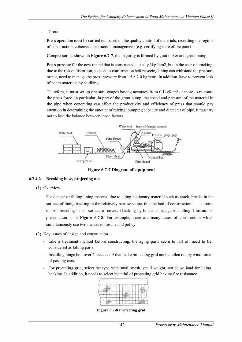
The Project for Capacity Enhancement in Road Maintenance in Vietnam Phase II
142 Expressway Maintenance Manual
- Grout
Press operation must be carried out based on the quality control of materials, recording the regime
of construction, coherent construction management (e.g. certifying state of the pour)
Compressor, as shown in Figure 6.7-7, the majority is formed by gout mixer and grout pump.
Press pressure for the new tunnel that is constructed, usually 3kgf/cm2, but in the case of cracking,
due to the risk of distortion, so besides confirmation before seeing lining can withstand the pressure
or not, need to manage the press pressure from 1.5 2.0 kgf/cm2. In addition, have to prevent leak of beam materials by caulking.
Therefore, it must set up pressure gauges having accuracy from 0.1kgf/cm2 or more to measure
the press force. In particular, in part of the grout pump, the speed and pressure of the material in
the pipe when concreting can affect the productivity and efficiency of press that should pay
attention in determining the amount of mixing, pumping capacity and diameter of pipe, it must try
not to lose the balance between those factors.
Figure 6.7-7 Diagram of equipment
Breaking base, projecting net
(1) Overview
For danger of falling lining material due to aging factionary material such as crack, breaks in the
surface of lining backing in the relatively narrow scope, this method of construction is a solution
to fix protecting net in surface of covered backing by bolt anchor, against falling. Illustrations
presentation is in Figure 6.7-8. For example, there are many cases of construction which
simultaneously use two measures: rescue and policy
(2) Key issues of design and construction
- Like a treatment method before constructing, the aging parts seem to fall off need to be considered as falling parts.
- Installing hinge bolt over 2 pieces / m2 that make protecting grid not be fallen out by wind force
of passing cars.
- For protecting grid, select the type with small mesh, small weight, not cause load for lining backing. In addition, it needs to select material of protecting grid having fire resistance.
Figure 6.7-8 Protecting grid
The Project for Capacity Enhancement in Road Maintenance in Vietnam Phase II
143 Expressway Maintenance Manual
Concrete blowing
(1) Overview
This is a construction method by blowing grout and reinforced concrete at 100 150mm of thickness in surface of lining at a relatively wide range, is complete repair-assisted solution or repair a part of
the lining’s surface for trouble of peeling the lining’s surface of the tunnel. If there is not a reliable
guarantee of adhesion between gunite concrete and lining concrete, it may cause peeling of the blowing
material. So, in the blowing construction method, treat lining surface is conducted, as splinter proof,
to have integration of materials by metal grid attached consistent anchor with the lining works were
done before.
However, this method of construction has many different types of materials, depending on the degree
of deformation and condition of construction; therefore, it must choose the appropriate type
responding to the situation.
- Grout + metal grid
- Concrete + metal grid
- SFRC (Servo-assisted concrete with steel wire)
- GFRC (Servo-assisted concrete with glass wire)
(2) Key issues of design and construction
It should stipulate structure of concrete and blowing grout to gain grout type with good strength,
adhesion and construction. In particular, in the case of mixing glass and steel wire, it needs to calculate
carefully effectiveness and construction.
In order to support in bending and anti-peeling by integration, adding metal grid that is coherent with
disfigurement. However, if metal grid is escaped after blowing will cause corrosion, cracking, peeling,
need to set up the covering appropriately.
Gunite concrete often arises rebounding, so in the case of constructing by passing a side, must pay
attention to the exchange of gas and dust, precaution not to affect the rebounding for vehicles passing
through.
When constructing base floor, drying occurs too quickly will generate cracks, is the cause of
subsidence, therefore, it needs to pay attention to concrete maintenance in the first time and avoid
constructing with low temperature
To have integration with lining backing that was constructed before, need to establish breech button 1
piece/m2.
After constructing gunite concrete, there is a case appearing the phenomenon of moving rock on
outside wall. Main cause is due to limitation with low background and lack of quickly stable admixture.
It should be noted during the construction process.
Construction method of gunite concrete having dry type and wet type, each one has its own advantages
and disadvantages. Note to the condition of the construction site to choose the method of construction.

The Project for Capacity Enhancement in Road Maintenance in Vietnam Phase II
144 Expressway Maintenance Manual
Table 6.7-11 Comparison between the method of dry and wet construction.
Dry construction Wet construction Quality of concrete
Because of mixing water with dry substance by nozzle, quality depends on heat miscibility and capacity of operator.
Because it calculated types of materials before (including water) exactly, it is easy to manage quality.
Limitation of action
Dry material was availably mixed at certain level, so there is no limitation in action of material delivery.
Having crossed limitation in action of material delivery
Distance of displacement
Can displace at a relatively long distance Not be suitable to displace at a long distance
Generated dust Relatively much Relatively little Rebounding Relatively much Relatively little Space of action Small-size action machine Large-size action machine
Figure 6.7-9 Illustration of gunite concrete maintenance by SFRC (unit: mm)
Locking bolt
(1) Overview
For the deformation caused by external forces such as the elastic pressure, unsymmetrical pressure,
this method of construction will close the locking bolt into the base, forming the assumed structure in
a part of the base around the available structure, in order to achieve effectiveness of internal pressure,
raising moving pressure of base.
Locking bolt is classified according to adhesive form is the comprehensive and dead end cohesive
types, in addition, classified according to the hole drilling method, there are grout and the type of hole
drilling (Figure 6.7-10). However, it should use locking bolt having dead end exposure will be limited
by hard rock or average hard rock, hereinafter present a comprehensive cohesive is major (Figure
6.7-11).
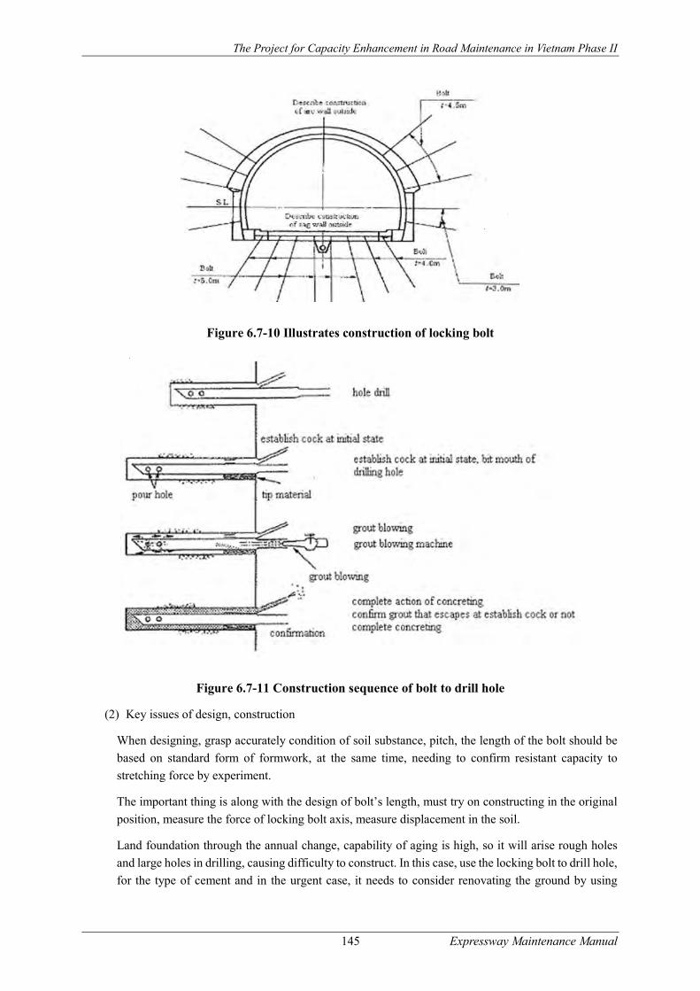
The Project for Capacity Enhancement in Road Maintenance in Vietnam Phase II
145 Expressway Maintenance Manual
Figure 6.7-10 Illustrates construction of locking bolt
Figure 6.7-11 Construction sequence of bolt to drill hole
(2) Key issues of design, construction
When designing, grasp accurately condition of soil substance, pitch, the length of the bolt should be
based on standard form of formwork, at the same time, needing to confirm resistant capacity to
stretching force by experiment.
The important thing is along with the design of bolt’s length, must try on constructing in the original
position, measure the force of locking bolt axis, measure displacement in the soil.
Land foundation through the annual change, capability of aging is high, so it will arise rough holes
and large holes in drilling, causing difficulty to construct. In this case, use the locking bolt to drill hole,
for the type of cement and in the urgent case, it needs to consider renovating the ground by using

The Project for Capacity Enhancement in Road Maintenance in Vietnam Phase II
146 Expressway Maintenance Manual
concrete materials such as urethane, silicon glue. However, in the cracked tunnels, pressure may
increase the risk of breakage, so it needs to construct at pressure does not affect the lining.
Depending on the condition specifying the route should select construction machine and length of
bolts.
Depending on the state of deformation, there is a case to create pressure
Table 6.7-12 Characteristics to select comprehensive adhesive- type locking bolt
Types of bolt Cement Field of application
(level of spring water) Function Drill jig
Backfill type by grout
Grout Much ↕
Little
Hole, grout backfill, bolt with type of comprehensive adhesive when plugging bolt
Drill jumbo
Type of compression
Cement passage having quick
toughness, dry grout
Much ↕
Little
Pour adhesion at level 1.3 shot
Drill jumbo Leg drill
Self-drill hole type
Grout, urethane Much
↕ Little
Pour adhesion material from the central hole Using screw should be optional on selecting the length of bolt Can select auger according to ground base Good adhesion by deformed steel bar
Drill jumbo Leg drill
Casing type Grout, urethane Much ↕
Little
Be easy to construct in ground having subsidence Can pour at high pressure Can use equipment, construction machines that have ever had
Drill jumbo
Anti-seepage construction
(1) Overview
This is the most common method of construction, regarded as a policy for the watermark by cracking
of lining and long-term used concrete.
However, this method is suitable for the case of water leak is not agglomerated, for case of anti-setting
water in cold places.
To select the effective water leakage protection technology, we need to rely on status of water leakage
and environmental conditions. The methods can be combined in proper way. Typical water leakage
protection technology and selection table of water leakage protection methods are shown in Figure
6.7-12 and Table 6.7-13.
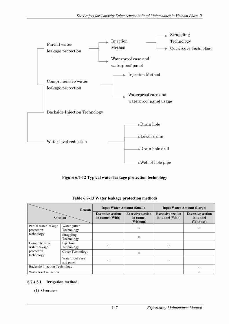
The Project for Capacity Enhancement in Road Maintenance in Vietnam Phase II
147 Expressway Maintenance Manual
Figure 6.7-12 Typical water leakage protection technology
Table 6.7-13 Water leakage protection methods
Reason
Solution
Input Water Amount (Small) Input Water Amount (Large)
Excessive section in tunnel (With)
Excessive section in tunnel (Without)
Excessive section in tunnel (With)
Excessive section in tunnel (Without)
Partial water leakage protection technology
Water gutter Technology ○ ○
Straggling Technology ○
Comprehensive water leakage protection technology
Injection Technology ○ ○
Cover Technology ○
Waterproof case and panel
○ ○
Backside Injection Technology ○
Water level reduction ○
Irrigation method
(1) Overview
Partial water
leakage protection
technology
Injection
Method
Waterproof case and
waterproof panel
Straggling
Technology
Cut groove Technology
Comprehensive water
leakage protection
technology
Backside Injection Technology
Water level reduction
Technology
Injection Method
Waterproof case and
waterproof panel usage
Drain hole
Lower drain
Drain hole drill
Well of hole pipe

The Project for Capacity Enhancement in Road Maintenance in Vietnam Phase II
148 Expressway Maintenance Manual
Irrigation Method is a way that we make water along the leaking location so that the water line is
not blocked, mainly for maintaining the spatial landscape in the tunnel. It also helps us adjust the
cross section of water output depending on the more or less amount of drainage water.
As shown in Figure 6.7-13, this is vertical water gutter technology that is designed as a water pipe
outside the tunnel, and the tunnel surface makes up U or V-shaped. The vertical water gutter method
is one of irrigation methods through the installation of plastic or synthetic rubber pipe.
In vertical water gutter technology, the material on the surface of the concrete tray is fixed by rivets.
Although it is not beautiful, it is easy to clean up in case of congestion by cement.
Straggling Technology is the one that grooves are made in the concrete surface for irrigation, in
which U-cutting method, which is cut from rectangular, can ensure cross section is larger than the
V-cut ones and build broken lines, curves, ... In addition, because the surface is protected by
synthetic rubber which is elasticity, highly insulated, it is useful for the solid surface.
The two methods as mentioned above are selected depending on the location and amount of water
leakage.
(2) Key issues of design and construction
- Select materials for long-term use (durability)
- Understand the status of water input, and ensure cross-sectional area of the drain pipe in
accordance with the amount of water flowing into it.
- Based on the relationship between the location of machine and the quality of slice surface in
the mine, it is necessary to look at the water-spout installation’s location carefully.
Straggling Technology Vertival water gutter technology
Figure 6.7-13 Irrigation Method
Technical measures to block water
(1) Introduction
The technical measures to block water is the measures which reduces the amount water released by
blocking water flow in small gaps because water flows along the joints or cracks-connectors where
water leakage generates.
As described in Figure 6.7-14 and Figure 6.7-15, these measures include blocking the streams and
cover crack without groove.
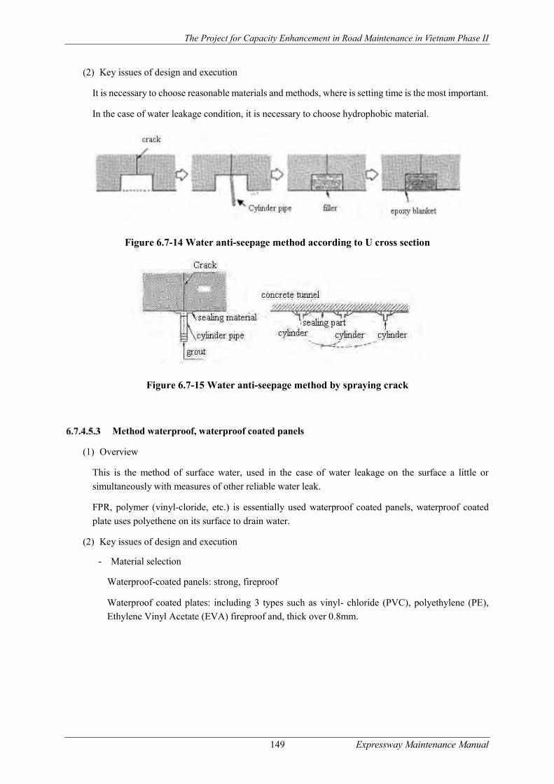
The Project for Capacity Enhancement in Road Maintenance in Vietnam Phase II
149 Expressway Maintenance Manual
(2) Key issues of design and execution
It is necessary to choose reasonable materials and methods, where is setting time is the most important.
In the case of water leakage condition, it is necessary to choose hydrophobic material.
Figure 6.7-14 Water anti-seepage method according to U cross section
Figure 6.7-15 Water anti-seepage method by spraying crack
Method waterproof, waterproof coated panels
(1) Overview
This is the method of surface water, used in the case of water leakage on the surface a little or
simultaneously with measures of other reliable water leak.
FPR, polymer (vinyl-cloride, etc.) is essentially used waterproof coated panels, waterproof coated
plate uses polyethene on its surface to drain water.
(2) Key issues of design and execution
- Material selection
Waterproof-coated panels: strong, fireproof
Waterproof coated plates: including 3 types such as vinyl- chloride (PVC), polyethylene (PE),
Ethylene Vinyl Acetate (EVA) fireproof and, thick over 0.8mm.

The Project for Capacity Enhancement in Road Maintenance in Vietnam Phase II
150 Expressway Maintenance Manual
Figure 6.7-15 Illustrate using anti-seepage
- Considering the suitable position of cross-sectional shape, make sure the cross-sectional area
of the tunnel arch.
- Before proceeding, it is required to perform cables protection and sanity, cleaning the dirt,
preparing for construction can proceed smoothly.
- Both waterproof covers and panels must be carried out treatments at the edges and margins
correctly, take caution not to let water leak for a long time.
- With crack rails, it is necessary to create specialized window design for supervision and
inspection.
Method of backside covers spraying
(1) Overview
This is the method in which a liquid like cement or molten glass is plastered from the inner surface of
the tunnel or from the ground surface, to the back of the tunnel or to the land in the middle of the
mountains in order to prevent water leakage.
In addition, generally, counter-tactics for soil pressure would normally be carried out, so this method
is also used in the case of binding tunnel to the mountain land through filling the gap in the dorsal
surface of the tunnel, to balance the pressure that the land impacts on the tunnel.
(2) Key issues of design and construction
In the selection of wedging agents and methods of wedging, it is necessary to fully explain the
principles of effective filling-up and osmotic properties of the wedging agents, then consider soil
conditions and the other conditions. In addition, the molten glass is not considered as the only effective
waterproof material, but the method of wedging spray with ash powder burnt at high temperature…
also needs to be developed.
The conditions required in the wedging spray are stated in the following categories:
- To be able to penetrate deeply into the interstices of the soil and cracks of the rocks, it is necessary to reduce the viscosity in the first period (viscosity before solidification and
gelatinization) as much as possible.
- After solidification and gelatinization, the spray material should be observed as highly durable,
not to be divided, shrink... but show stable waterproof property.
- Stabilize all the environmental factors in the long term.

The Project for Capacity Enhancement in Road Maintenance in Vietnam Phase II
151 Expressway Maintenance Manual
- The mixing and using of wedging agent are quite simple, moreover, it is also easy to adjust its
solidification and gelatinization time.
- Solidification and gelatinization reactions are hardly affected by the diversity of chemical and
physical properties of the mountain ground.
- Does not include matters polluting the mountain area and the groundwater.
Because the crack can expand as a result of spraying pressure, so before implementation, along with
analyzing whether the tunnel can withstand wedging pressure, it is also necessary to maintain the
spraying pressure at about 1.5 2kgf /cm2.
After spraying, to prevent the rise of the groundwater, it should be designed to create drainage holes
on the wall.
(3) Common measures to assess injection efficiency
Test drill holes and collecting documents, along with the condition assessment through observation
and phenolphthalein reaction, the soil strength also needs to be good for the air compression test.
Check the efficiency in blocking water for the test of water soaking into the field test.
Suitability between environmental conditions and the wedging spray method is presented in Table
6.7-14.
Table 6.7-14 Suitability between environmental conditions and the wedging spray method
Spraying Method/ Ground condition
PP Double Tube Packer
Single Tube – PP Road
Double Tube -PP
neighboring coalescence
Double Tube – PP Road resultant
Grouting- PP
Blow grout
Rock sheet
Normal crack ○ Multiple crack ○ ○ Break each particle ○ ○ Sand surplus ○ △ Clay ○ △
Binding formation
Array lava stone ○ △ △ △ Semi-frozen sandstone ○ △ ○ Flexible stone with mud state
○ △
Normal soil
horizon
Even and steady sand ○ ○ △ ○ Medium sand ~ crude ○ △ ○ ○ ○ Grained sand ○ ○ ○ ○ General sand ○ ○ △ Clay ○ ○ ○ ○ △
○: accommodated △: unsure accommodation
Lowering the water table
(1) Overview
This construction method is lowering the water table in the back of the tunnel liner or groundwater
levels near the construction of the tunnel, to prevent water leakage with interstitial sand drift into
crevices.
The common method is the construction of lowering the water table of the behind tunnel’s lining, to
arrange installation of the drainage holes, deep down drains response; but in special situations is

The Project for Capacity Enhancement in Road Maintenance in Vietnam Phase II
152 Expressway Maintenance Manual
lowering the water table near the construction of the tunnel, it must consider the construction to the
case of horizontal drains in the direction of the tunnel axis.
(2) Key issues of design and construction
- To prevent incidents such as drainage holes rules, it is necessary to use materials with filtering.
- In the case of lower drainage system, should be noted carefully, grasp the disfigurement occurs.
- When applied to the drain, in addition to the usual investigation, need to understand the status
of groundwater and geological conditions of the peripheral area of the tunnel.
- Need to handle the end of the flow from the end of the drainage holes to drain
Figure 6.7-16 Drainage hole
Internal rolled concrete
(1) Overview
This implementation method is applied to the phenomenon of deformation caused by damage to the
material as well as the impact of external forces such as pressure, in the case, it can be easily seen that
the coil thickness which is still spacious enough inside in the cross section of the tunnel, can reinforce
more concretes into available lining coat (180kgf/cm2 design strength), increasing surface area in order
to strengthen the overall endurance capacity of works.
This method is not very suitable in case of continuous traffic, so it is recommended to apply
construction methods called PCL (the method of using armored concrete arch bars with highly
mechanical strength in light red color which have been shed availably at the assembly construction
site inside the tunnel), thereby reducing the traffic problem.
(2) Key issues of design and construction
- Decision on coil thickness must be considered carefully based on the inner damaged state,
external forces such as pressure, excessive space inside the cross-sectional area … as well as
considering similar cases in the past. Besides, it is feasible for rolled thickness of 12.5 cm or
more. In the case of about 12.5 to 15 cm, it is necessary to discuss to maintenance contractor for
the feasibility and the economy.
- On the disposal prior to the construction, to ensure adhesion of the concrete tunnel, the cross-

The Project for Capacity Enhancement in Road Maintenance in Vietnam Phase II
153 Expressway Maintenance Manual
sectional tunnel must have a depth of 1 cm to 2 cm, as shown in Figure 6.7-17.
(a)
(b)
Figure 6.7-17 (a) - Construction method of internal arc concrete; (b) - Illustrate PCL construction method (unit:mm)
- In case of being designed in the unified purposes the previous construction, depending on the
construction, after applying adhesive glue to joints, installed on 2 sheets/m2.The thickness of the
inner layer is made thicker while not using the same previous methods, it requires to use the
tempered glass construction and waterproofing, as shown in Figure 6.7-17 (b).
- In case of inner section not having the extra space, reinforce the tempered glass capacity, and
use anti-fall caused by cracks, using efficient construction method as sticking fiberglass or
carbon fiber.
Cleaning the road at tunnel
(1) Introduction
Road tunnel is often dirty because of rain and there are no places to flow, so the best way is to regularly
clean the road, however in fact the cleaning of the road tunnel is usually carried out at the same time
as the normal road surface.
When cleaning the road tunnel, it is necessary to consider the status of dirt and traffic planning. Tunnel
cleaning can be considered as periodic maintenance.
(2) Cleaning the tunnel’s walls and furniture

The Project for Capacity Enhancement in Road Maintenance in Vietnam Phase II
154 Expressway Maintenance Manual
Wall and the interior materials in the basement can obstruct the view when soiled; reduce lighting
efficiency so it needs to be maintained in a good condition.
The wall of road tunnel is blackened by automobile’s smoky emission, which cannot be washed by
water. In order to increase effective of cleanness, it should be cleaned by water with detergents. When
using detergent, do not select the type of corrosive equipment in the road tunnel but select the neutral
type, because it can be dangerous for the vehicles and for the cleaners.
In addition, it will be more effective by using sprayed detergent together with machine brush. Waste
wash water should be considered as it can affect the environment.
In addition, when cleaning, it should be careful not to break down the equipment used in an emergency
and should not let them watered, so as not to degrade the functionality of these devices.
(3) Cleaning lighting devices
The lighting devices in the road tunnel can be contaminated by smoke and dust to impair lighting
function. It should be considered for maintaining and cleaning periodically.
It is noted that should use soft cloth or cotton tip to clean lighting devices in order not to affect the
glass of the lamps and reflector plates. At the same time while cleaning, it should be careful not to
splash the lights or the wiring.
(4) Cleaning sewage system.
Wastewater system at the mouth of the road tunnel often impaired in terms of function as sand, dust
settle and harden. In addition, in case the drainage in road tunnel is not good it will lead to damage the
tunnel pavement, to dust and to ruin the coating walls and furniture in the road tunnel. So it is necessary
to carry out cleaning sewage system periodically.
Water mostly used when cleaning the road tunnels, so before cleaning, it is necessary to check the
status of drainage and culverts, and to keep them in a good condition.
2) Cleaning other devices
When the warning device is abnormal, other display devices located in the road tunnels contaminated,
it will make visual observation decreased so together with checking the functions of those devices, it
also needs to clean the surface of them.
3) Frequency of cleaning
Frequency of cleaning should be based on actual conditions, such as type of road, traffic volume, the
character of the surrounding area, and in general, in case of being more and more traffic, the frequency
of cleaning should be increased.
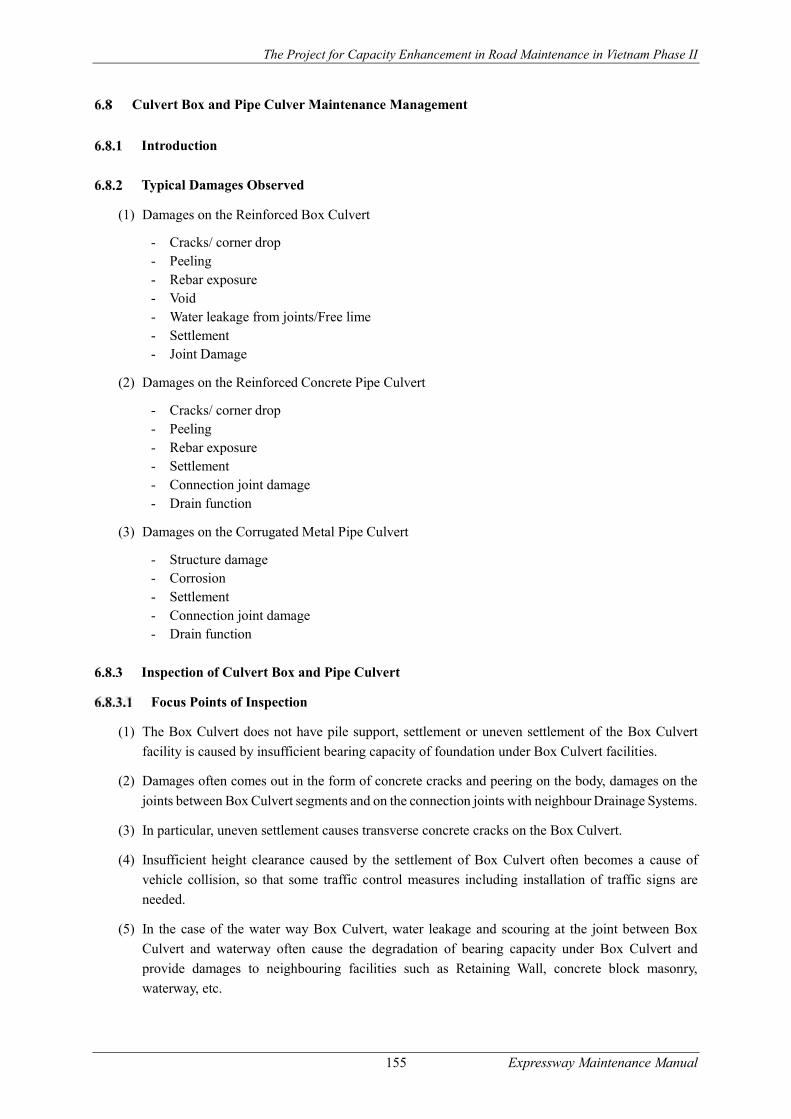
The Project for Capacity Enhancement in Road Maintenance in Vietnam Phase II
155 Expressway Maintenance Manual
Culvert Box and Pipe Culver Maintenance Management
Introduction
Typical Damages Observed
(1) Damages on the Reinforced Box Culvert
- Cracks/ corner drop - Peeling - Rebar exposure - Void - Water leakage from joints/Free lime - Settlement - Joint Damage
(2) Damages on the Reinforced Concrete Pipe Culvert
- Cracks/ corner drop - Peeling - Rebar exposure - Settlement - Connection joint damage - Drain function
(3) Damages on the Corrugated Metal Pipe Culvert
- Structure damage - Corrosion - Settlement - Connection joint damage - Drain function
Inspection of Culvert Box and Pipe Culvert
Focus Points of Inspection
(1) The Box Culvert does not have pile support, settlement or uneven settlement of the Box Culvert
facility is caused by insufficient bearing capacity of foundation under Box Culvert facilities.
(2) Damages often comes out in the form of concrete cracks and peering on the body, damages on the
joints between Box Culvert segments and on the connection joints with neighbour Drainage Systems.
(3) In particular, uneven settlement causes transverse concrete cracks on the Box Culvert.
(4) Insufficient height clearance caused by the settlement of Box Culvert often becomes a cause of
vehicle collision, so that some traffic control measures including installation of traffic signs are
needed.
(5) In the case of the water way Box Culvert, water leakage and scouring at the joint between Box
Culvert and waterway often cause the degradation of bearing capacity under Box Culvert and
provide damages to neighbouring facilities such as Retaining Wall, concrete block masonry,
waterway, etc.

The Project for Capacity Enhancement in Road Maintenance in Vietnam Phase II
156 Expressway Maintenance Manual
Inspection Points
Road facility inspection for culvert facilities shall be implemented on the inspection points shown in
Table 6.8-1 for Box Culverts and in Table 6.8-2 for Pipe culverts
Table 6.8-2Table 6.8-1 Inspection Points (Box Culverts)
Facility Member Damage Initial
inspection Routine
inspection
Periodic inspectio
n
Emergency
inspection
Detailed Inspectio
n
Box Culvert
Reinforced Concrete Box Culvert
Cracks/ corner drop X -------- X X
As required
by Routine
or Periodic Inspectio
n
Peeling X -------- X X
Rebar exposure X -------- X X
Void / Honey comb
X -------- X X
Water leakage from joints/Free lime
X -------- X X
Settlement / Scoring
X X X X
Joint Damage X -------- X X
Table 6.8-2 Inspection Points (Pipe Culverts)
Facility
Member Damage Initial
inspection Routine
inspection
Periodic inspecti
on
Emergency
inspection
Detailed Inspecti
on
Pipe Culvert
Reinforced concrete pipe culvert
Cracks/ corner drop -------- -------- X X As required
by Routine
or Periodic Inspecti
on
Peeling -------- -------- X X Rebar exposure -------- -------- X X Settlement -------- X X X Connection joint damage
-------- -------- X X
Drain function -------- -------- X X
Corrugated metal pipe culvert
Structure damage -------- -------- X X As required
by Routine
or Periodic Inspecti
on
Corrosion -------- -------- X X Settlement -------- X X X Connection joint damage
-------- -------- X X
Drain function
-------- -------- X X
Inspection Methods and Frequencies
Inspection methods and inspection frequencies in principle shall follow the relevant articles of this
Guideline.
Evaluation of Inspection Results
(1) Evaluation of the results of routine inspection, periodic inspection and emergency inspection shall
be conducted, following relevant articles in this Guideline. Sample evaluation criteria for Concrete

The Project for Capacity Enhancement in Road Maintenance in Vietnam Phase II
157 Expressway Maintenance Manual
Box Culverts and Pipe Culverts are shown in ANNEX-G. Also, particular notes for the evaluation
of some major damages are described below;
(2) The Box Culvert does not have pile support, so that culver box is in general set higher than the design
height, assuming some settlement caused by consolidation of bearing layer. However, if settlement
occurs larger than expected, gaps in height between approach road and the culvert becomes wider.
The damage is rated as “C” in this Guideline.
(3) When water leakage occurs at the end joint of culver box and infiltrates into the bearing layer of the
culver box, it may degrade the bearing capacity of the culver box or scour the foundation of
neighbour facilities. The damage is rated as “C” in this Guideline.
(4) When damages include the opening of gaps and difference in height on the joints of pipe culver box
facilities progress, it may break water-stop plate, cause water leakage and falling of water-stop plate.
The damage is rated as “C” in this Guideline.
(5) When drain function is degraded due to the damages at the joints of Drainage Systems or due to the
piling of debris in the drain systems, thereby causing water leakage from the joints, the damage is
rated as “C” in this Guideline.
Data Registration and Reporting
Registration of inspection data shall be conducted, following relevant articles in this Guideline.
Planning and Implementation of Maintenance and Repair
Planning and implementation of maintenance repair work for culvert box and pipe culvert facilities
shall follow that for road tunnels, “0
Road Tunnel Maintenance Management”.
Retaining Wall Maintenance Management
Introduction
Retaining walls are structural support to prevent slope failures or landslides where natural or
structurally protected slopes cannot ensure the stability of slopes due to topographic reasons or limited
availability of land. Retaining walls shall have damages such as cracking, swelling, falling down due
to the change of load working behind wall or the tope of wall, or may be leaned or broken due to
subsidence of wall foundation.
This manual regulates
To renovate and upgrade the retaining walls, embankments system, the topography of the area,
geological features, biological condition of the carpet slope, materials, land use status, meteorological
characteristics.... should be fully aware of and understood properly.
Classification of Retaining Walls
Retaining walls can be classified by used materials and the shape of walls, but in general fall into the
following walls;
a. Stone or concrete block masonry
The Project for Capacity Enhancement in Road Maintenance in Vietnam Phase II
158 Expressway Maintenance Manual
b. Gravity-type retaining wall
c. Cantilever-type retaining wall
d. Counterfort retaining wall.
Typical Damages Observed
Table 6.9-1 Damages by the Type of Retaining Wall
Retaining wall Damages Stone or concrete block masonry Gravity-type retaining wall Cantilever-type retaining wall Counterfort retaining wall.
- Cracks, swelling - Concrete peeling - Steel bar exposure - Settlement or movement - Abnormal joint gap - Scouring
Inspection of Retaining Walls
Focus point of inspection
(1) Damages of retaining walls shall often appear in unusual weather conditions such as heavy rain,
storm, flooding, earthquakes etc., so that emergency inspection shall be implemented immediately
after such disasters.
(2) In case big damages are detected, detailed investigation shall be implemented to evaluate potential
hazard and to find out countermeasures. In order to facilitate the designing of repair works, road
inventory data including retaining wall initial design data should be preserved.
(3) Focus points of inspection are shown below;
- Any concrete cracks, joint cracks, swelling and deterioration of wall surface
- Leaning, sliding and subsiding of retaining wall
- Damages on the drain holes, water reserve on the back fill and water seepage
- Gaps and voids between wall body and backfill soil
- Damages on wall foundation
In particular, much attention shall be paid on the damages on the drainage systems. The damages often
cause imbalanced load working on the back of retaining wall, thereby give serious damages on the
wall body.
Inspection points
Inspection points of retaining walls are summarized in Figure 6.9-1 However, the table regulates the
minimum requirement of inspection points, so that users can supplement some inspection points
whenever needed.
Figure 6.9-1 Inspection Points for Retaining Walls
Facility Member Damage Initial
inspection
Daily inspection
Periodic inspection
Emergency
inspection
Detailed Inspection
Retailing walls
Reinforced concrete retailing walls and
Cracks X X X X As required by Routine or Periodic Inspection
Peeling X X X X Steel bar exposure
X X X X

The Project for Capacity Enhancement in Road Maintenance in Vietnam Phase II
159 Expressway Maintenance Manual
Facility Member Damage Initial
inspection
Daily inspection
Periodic inspection
Emergency
inspection
Detailed Inspection
Stone Masonry
Settlement or movement
X X X X
Abnormal joint gap
X X X X
Scouring X X X X Poor drainage or spring water
X X X X
(Note) X: Inspection items.
Inspection methods and Frequencies
Inspection methods and inspection frequencies in principle shall follow the relevant articles of this
guideline.
Evaluation of Inspection Results
Evaluation of the inspection results obtained in routine inspection, periodic inspection and emergency
inspection shall be conducted, following relevant articles in this Manual. Sample evaluation criteria
for the inspection results of retaining walls are shown in ANNEX-C.
Registration of Inspection Data and Reporting
Registration of inspection data and reporting shall be conducted, following relevant articles in this
guideline.
Planning and Implementation of Maintenance and Repair Work for Retaining Wall
Maintenance and repair methods for retaining walls shall basically follow those for concrete and
reinforcing concrete facilities. Some particular issues to be considered in maintaining and repairing
retaining walls are shown below:
(1) Improper water treatment
Drainage system plays an important role in the maintenance and the repair of retaining walls. If it does
not function well, ground water or rain water shall accumulates in the backfill soil and causes increase
in soil pressure, thereby causes significant negative effects to the wall body. It is therefore necessary
to conduct appropriate water treatment and prevent water infiltration into the backfill soil. It is also
necessary to lead water to downstream drainage systems.
Some typical measures to treat these water are shown as follows;
a. Prevention of surface water infiltration
- To implement the coverage of slopes by mortar or concrete spraying, concrete blocks, etc. as
shown in Figure 6.9-2.
- To install a U-shaped drainage system on the slope berm as shown in the figure.

The Project for Capacity Enhancement in Road Maintenance in Vietnam Phase II
160 Expressway Maintenance Manual
Figure 6.9-2 Sample Water Treatment
b. Release of water pressure
A drainage hole shall be installed to release water pressure out of the wall which is installed once
every 2-3m2 in water accumulation area on the back. Drainage holes is in general made of PVC
plastic pipe with a diameter of 5 to 10 cm. Care should be paid not to fill the pipes with concrete
spills or debris during construction.
(2) Gaps or voids arising between retaining walls and backfill soil
It is necessary to fill gaps and voids between retaining walls and backfill soils by using appropriate
materials including cobbles, crashed stones and sand. The following shows the implementation methods for small damages.
- Clean and scratch out damaged joint mortar, soil and plants using air compressor, water sprayer,
hammer or chisel,
- At the points where the joint needs to be completely renewed, the stone or brick should be
removed temporarily until a new mortar bed is placed,
- Water the joint surfaces where fresh mortar has to be applied,
- Mix a mortar of cement and sand as required (1 cement: 3 sand) and add only enough water to
permit mortar to be applied,
- Apply fresh mortar to joint, filling all space available, compacting with a suitable wooden
hammer. Do not use mortar which has fallen on the ground,
- Smooth joints with a suitable tool (a piece of rubber or plastic water hose, or bent reinforcing
steel),
- The final mortar surface should be placed slightly from the stone/brick surface to achieve a tidy
finish,
- In the dry season, mortar can dry out quickly. Prevent this by sprinkling water on joints after
the mortar has set and until mortar has completely hardened. Alternatively cover the work area
with wet jute sacks or similar,
- Clean visible stone or brick surfaces which have been stained by mortar or cement-water in the
process of the work so that the finished work will present a neat appearance,
- Remove surplus materials and leave the site in a clean and tidy condition.
(3) Swelling of wall body
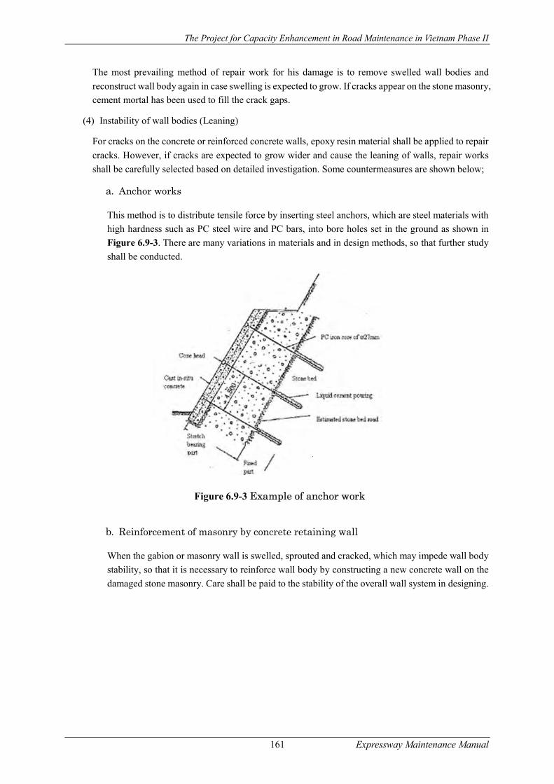
The Project for Capacity Enhancement in Road Maintenance in Vietnam Phase II
161 Expressway Maintenance Manual
The most prevailing method of repair work for his damage is to remove swelled wall bodies and
reconstruct wall body again in case swelling is expected to grow. If cracks appear on the stone masonry,
cement mortal has been used to fill the crack gaps.
(4) Instability of wall bodies (Leaning)
For cracks on the concrete or reinforced concrete walls, epoxy resin material shall be applied to repair
cracks. However, if cracks are expected to grow wider and cause the leaning of walls, repair works
shall be carefully selected based on detailed investigation. Some countermeasures are shown below;
a. Anchor works
This method is to distribute tensile force by inserting steel anchors, which are steel materials with
high hardness such as PC steel wire and PC bars, into bore holes set in the ground as shown in
Figure 6.9-3. There are many variations in materials and in design methods, so that further study
shall be conducted.
Figure 6.9-3 Example of anchor work
b. Reinforcement of masonry by concrete retaining wall
When the gabion or masonry wall is swelled, sprouted and cracked, which may impede wall body
stability, so that it is necessary to reinforce wall body by constructing a new concrete wall on the
damaged stone masonry. Care shall be paid to the stability of the overall wall system in designing.
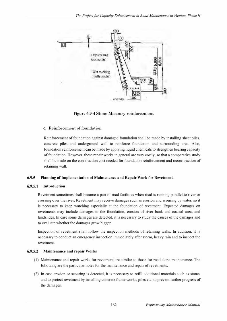
The Project for Capacity Enhancement in Road Maintenance in Vietnam Phase II
162 Expressway Maintenance Manual
Figure 6.9-4 Stone Masonry reinforcement
c. Reinforcement of foundation
Reinforcement of foundation against damaged foundation shall be made by installing sheet piles,
concrete piles and underground wall to reinforce foundation and surrounding area. Also,
foundation reinforcement can be made by applying liquid chemicals to strengthen bearing capacity
of foundation. However, these repair works in general are very costly, so that a comparative study
shall be made on the construction cost needed for foundation reinforcement and reconstruction of
retaining wall.
Planning of Implementation of Maintenance and Repair Work for Revetment
Introduction
Revetment sometimes shall become a part of road facilities when road is running parallel to river or
crossing over the river. Revetment may receive damages such as erosion and scouring by water, so it
is necessary to keep watching especially at the foundation of revetment. Expected damages on
revetments may include damages to the foundation, erosion of river bank and coastal area, and
landslides. In case some damages are detected, it is necessary to study the causes of the damages and
to evaluate whether the damages grow bigger.
Inspection of revetment shall follow the inspection methods of retaining walls. In addition, it is
necessary to conduct an emergency inspection immediately after storm, heavy rain and to inspect the
revetment.
Maintenance and repair Works
(1) Maintenance and repair works for revetment are similar to those for road slope maintenance. The
following are the particular notes for the maintenance and repair of revetments,
(2) In case erosion or scouring is detected, it is necessary to refill additional materials such as stones
and to protect revetment by installing concrete frame works, piles etc. to prevent further progress of
the damages.

The Project for Capacity Enhancement in Road Maintenance in Vietnam Phase II
163 Expressway Maintenance Manual
(3) Revetment slopes shall become vulnerable to scouring and landslides caused by water flow and wave.
The problem in general shall initiate from unseen slopes or foundation under water level. It is
therefore necessary to conduct emergency inspection to the facilities under water level in particular
after unusual weather conditions. When detecting any abnormalities of erosion or sliding, it is
necessary to immediately take actions to prevent further progress of these damages.
(4) When gabion is applied, it is necessary inspect wire corrosion and drop-out of rocks. When damage
is detected, it is necessary to repair and reinforce the facility by replacing with a new one or applying
concrete brock to the damages.
(5) In case there is a corrosion of foundation, it is necessary to reinforce foundations by applying piles,
wire cylinders, concrete frames to the damaged portions in order to prevent the further progress of
these damages.
Traffic Safety Facility Maintenance Management
Introduction
Traffic safety facilities in the road are mostly the products of the second industry and the forms and
types of these products are very diverse. Therefore, when carrying out maintenance, it should
understand not only functions but also types and forms of these facilities.
Most of these facilities have specified technical standards when installed. These technical standards
should be referred when checking their functions.
Where these facilities are broken, they need to be immediately restored to ensure their functionality.
Thus, from the beginning, there must be reserved spare parts or a complete purchasing system.
Classification of Traffic Safety Facilities
Traffic safety facility to be covered in this Guideline includes guard rail, guard cable and delineator/
road reflector
Typical Defects Observed
.Expected damages to be inspected for these facilities are as follows;
(1) Damages on the Guard Rail
- Main member damages; Breakage, dropout or tilting of beams, pipes, posts etc.
- Accessory damages; Breakage or dropout of mounting brackets, dropout or looseness of connection bolts, etc.
- Foundation damages; Cutting or dropout of anchor materials, or scouring around foundation which leads to the breakdown of guard facilities.
(2) Damages on the Guard Cable
- Main member damages; Breakage, dropout or tilting of pipes or guard posts etc.
- Accessory damages; Breakage or dropout of mounting brackets, dropout or looseness of connection bolts, etc.
- Foundation damages; Cutting or dropout of anchor materials, or scouring around foundation which leads to the breakdown of guard facilities.
(3) Damages on the delineator/ road reflector

The Project for Capacity Enhancement in Road Maintenance in Vietnam Phase II
164 Expressway Maintenance Manual
- Main member damages; Dropout or breakage of reflector, tilting of pipes etc.
- Accessory damages; Breakage or dropout of mounting brackets, dropout or looseness of connection bolts, etc.
- Foundation damages; Breakdown of anchor or scouring around foundation which leads to the breakdown of guard facilities.
(4) Damages on the Concrete Wall-type Guard Facilities
- Concrete cracks or corner dropout
Inspection of Traffic Safety Facilities
Focus Points of Inspection
(1) Guardrail facility damages are mostly the deformation caused by the force of vehicle accident.
However, damages are sometimes given to the neighbouring guardrail poles or brackets, so that
inspection is to be conducted on the neighbouring facilities.
(2) Corrosion often degrades the strength of the guardrail facility. When serious corrosion is found on
the guard posts or on the brackets during inspection, it is better to examine the thickness of the
member with ultrasonic thickness meter if necessary. A past study has clarified that design strength
of guard posts driven in the ground is maintained even 20 years after the installation if ground
condition is good. However, care should be paid to the facilities installed where ground water level
is high.
(3) Regarding the guard cables, when an upper cable sinks and touches to the lower cable by the weight
of inspection staff, the cable tension is deemed insufficient which needs restressing urgently.
Inspection Points
Road facility inspection for traffic safety facilities shall be implemented on the inspection points
shown in Table 6.10-1.
Table 6.10-1 Inspection Points for Traffic Safety Facilities
Structure Position Member Sort of damage
Initial inspection
Routine Inspection
Periodic inspection
Detailed Inspection
Traffic safety
Guard rail
Guard rail/Cable
Main member damages
------- X X
As required by Routine or Periodic Inspection
Accessory damages
------- ------- X
Corrosion ------- ------- X Foundation damages
------- ------- X
Main member damages
------- X X
Accessory damages
------- ------- X
Corrosion ------- ------- X Foundation damages
------- ------- X
Concrete Wall-type guard facility
Cracks/ /corner drop
------- X X
(Note) X: Inspection items.
The Project for Capacity Enhancement in Road Maintenance in Vietnam Phase II
165 Expressway Maintenance Manual
Inspection Methods and Frequencies
Inspection methods and inspection frequencies in principle follow the relevant articles stipulated in
this Guideline.
Evaluation of Inspection Results
(1) Evaluation of the results of routine inspection, periodic inspection and emergency inspection shall
be conducted, following relevant articles in this Guideline. Sample evaluation criteria for traffic
safety facilities are shown in ANNEX-H. Also, particular notes for the evaluation of some major
damages are described below;
(2) When deformation or severe damage to beams, pipes or cables or tilting of the support pole is
identified, it can no longer fulfil functions of protecting vehicles and drivers on board, so that the
damages are rated as “D” in this Guideline.
(3) When damages are identified, such as deformation, bending and or tilting of the beams, pipes, cables
and/or supporting poles, guard function is deemed slightly degraded, so that the damages are rated
as “C” in this Guideline,
(4) When damages are detected on the accessories of guard facilities, such as parts loss, loosening of
bolts which lead the main structure damage and so forth, the damages are rated as “C” in this
Guideline.
(5) When severe corrosion is observed on the beam, pipe, cable and/or support pole, degradation of
structural strength may occur. If the corrosion spreads wide area, it is rated as “C” in this Guideline,
requesting a detailed inspection by applying detailed evaluation of the corrosion including
examination of thickness measuring of main members. However, a past study has reported that guard
rail facility will work together with those located in the affected area to absorb shocks given by
vehicle collision. The affected area of vehicle collision is said about 20 meters, so that diagnosis
needs to be made on the facilities located in the affected area, rather than focusing on some specific
facilities.
Data Registration and Reporting
Registration of inspection data shall be conducted, following relevant articles in this Guideline.
Planning and Implementation of Maintenance and Repair Work
Safety Fence
(1) Introduction
Barriers are intended primarily to prevent cars from running out of control and crashing out of the
lanes or to the opposite direction, hitting pedestrians. Besides, they also have the following sub
functions:
- Keeping the car crash right in the current lanes
- Ensuring the safety of people in the cars.
- Ensuring the safety of pedestrians.
- Reducing damage significantly.
- Navigating the driver's view.

The Project for Capacity Enhancement in Road Maintenance in Vietnam Phase II
166 Expressway Maintenance Manual
In addition, it can also restrict the pedestrians from going outside the permitted areas and prevent
pedestrians or bicycles from going / riding out of the lanes
(2) Restoration
In case barriers are broken due to accidents or natural disasters, malfunction barriers are detected, it
needs to record the broken distance, parts, road’s condition and damage cause... and then process
immediately to promote full protection function of barriers
For the facilities damaged by traffic accidents, barriers account for an especially large proportion and
need to be done immediately at the site. When immediate recovery is not possible, for normal traffic
accidents, especially at the areas that are considered dangerous, there should be a temporary recovery
using available materials in emergency.
The principle of barrier recovery is conducting in accordance with forms, types that have already been
installed. In addition, depending on the damage, barriers must be replaced in accordance with
installation standard for a certain distance while reused barriers should be reserved for emergency.
In addition, due to the new surface coating (overlay), the distance between barriers and the road surface
is greatly reduced. Therefore, it is necessary to adjust height and replace barriers which are too rusty.
(3) Painting
If the barriers’ paint is peeled due to scratches or rust, it is necessary to conduct quick repaint. Paint
not only provides protection, but also has vision-navigating function. It also enhances the landscape.
Paint is vulnerable in traffic areas or in seaside areas where it is susceptible to salt. Therefore, the number times for painting should be more than usual. Before painting, the rusty layer
should be scraped off and phosphate lining treatment should be conducted.
(4) Cleaning the fence
With regard to dirty fence and the emissions of the cars involved in not only affect the function of
observability and the external beauty but also causes rust, wear and tear, so depending on the dirty
level, road situation, the amount of traffic that needs washing, cleaning accordingly.
Cleaning methods can vary depending on the degree of dirt but as per the case of contamination by
dust, mud, etc., you can use a cloth or soft brush and wash with water. Also, as per the cases
contaminated by car exhaust, black smoke, it is should be used by brushes, steel tufts to clean with
neutral detergent. And after using detergents, it should be used clean water to rinse several times to
avoid rust.
The cleaning of the long barriers cannot be done by human power, so it should be carried out by
machinery. When making use of the machine, it is necessary to use the vehicle equipped with
attachment.
Delineator/ road reflector
(1) Introduction
It is very important to maintain the common reflectiveness of delineators and road reflectors
Driving in the night to use reflected light rays emitted from the headlamp for the column-view, and
because of this delineators function driver should need to keep these columns reflect the brightness
with light evenly, not to the phenomenon of a distance, glistening, almost suddenly bright.

The Project for Capacity Enhancement in Road Maintenance in Vietnam Phase II
167 Expressway Maintenance Manual
(2) Maintenance and Repair
Because they are placed in the road, in regular patrols, we need to pay attention to the state of roadside
grass, or grow-out trees. If they affect the functions of delineators and road reflectors, they need cutting
and pruning.
Delineators and road reflectors work well in normal conditions. Thus, if they are tilted or damaged,
they will look very ugly and this affects landscape badly. In this case, they need be fixed quickly right
after inspection.
Traffic Management Facility Maintenance and Management
Introduction
Traffic management facilities are mostly the products of the second industry and the forms and types
of these products are very diverse. Therefore, when carrying out maintenance, it should understand
not only functions but also types and forms of these facilities.
Most of this auxiliary equipment has specified technical standards when installed. These technical
standards should be referred when checking their functions.
Where traffic management facility is broken, they need to be immediately restored to ensure their
functionality. Thus, from the beginning, there must be reserved spare parts or a complete purchasing
system.
Classification of Traffic Management Facility
Traffic management facility to be covered in this Guideline is Road Lighting and Traffic Signs.
Typical Defects Observed
(1) Damages on the Main Body of Traffic Sign
- Deformation or breakage of sign boards
- Deformation, instability and breakage of sign poles
- Deterioration and stain of sign boards
- Low luminance of sign boards
(2) Damages on the Accessories of Traffic Signs
- Loosening or dropout of bolts or nuts on the mounting brackets
Inspection of Traffic Management Facilities
Focus Point of Inspection
(1) Inspection of the street lighting equipment is different from that of tunnel lighting equipment because
the locations to set up the equipment are scattered largely. Main items for normal inspection are as
followed:
- Lightning status - Checking whether the protection caps are damaged or not - Status of attached lights
- Checking whether the lights are shifted and curved

The Project for Capacity Enhancement in Road Maintenance in Vietnam Phase II
168 Expressway Maintenance Manual
The common tests can be done by visual inspection, and can also be conducted in conjunction with
the daily afternoon patrols, but also depending on the situation of the relevant managed area, in some
cases, the object of patrols is only lighting equipment.
(2) For road signs, in regular patrolling, patrolling staffs should observe from patrol cars whether trees
and billboards alongside the streets obscure them or not, whether the signs and columns are damaged
or not. In addition, the items below should also be periodically tested. In case unusual weather
conditions such as strong winds and storms can be predicted, and as soon as they occur, the items
below should be temporary inspected
- Whether signs and columns are broken, stained or corroded.
- Whether paint and reflective substances are peeled.
- Whether signs are deviated or left out
- Status of lighting equipment
- Basic status
- Reflecting features (only in periodical inspection)
Inspection Points
Road facility inspection fir traffic management facilities shall be implemented on the inspection points
shown in Table 6.11-1 also illustrates inspection points for traffic sign.
Table 6.11-1 Inspection Points for Traffic Management Facilities
Structure Position Member Sort of damage Initial inspection
Daily inspection
Periodic inspection
Detailed Inspection
Traffic Management Facility
Traffic Signs
Traffic signs
Main member damages ------- X X
As required by Routine or Periodic Inspection
Accessory damages ------- ------- X
Corrosion ------- ------- X
Foundation damages ------- ------- X
Figure 6.11-1 Inspection Points for Traffic Sign
Inspection Methods and Frequencies
Inspection methods and inspection frequencies in principle follow the relevant articles stipulated in
this Guideline.
The Project for Capacity Enhancement in Road Maintenance in Vietnam Phase II
169 Expressway Maintenance Manual
Evaluation of Inspection Results
(1) Evaluation of the results of routine inspection, periodic inspection and emergency inspection shall
be conducted, following relevant articles in this Guideline. Sample evaluation criteria for traffic
signs are shown in ANNEX-I. Also, particular notes for the evaluation of some major damages are
described below;
(2) For the serious damages on the traffic signs including dropout, deformation or tilting of materials,
evaluation criteria for traffic safety facilities shall be applied.
(3) When traffic sign is not readable due to deterioration of paints, stains of sign boards or the peering
of reflection sheet, rating of “C” is applied in this Guideline.
(4) For corrosion on the foundation or on the accessories of traffic signs, evaluation criteria for traffic
safety facilities shall be applied.
Data Registration and Reporting
Registration of inspection data shall be conducted, following relevant articles in this Guideline.
Planning and Implementation of Maintenance and Repair
Where traffic management facilities are broken, they need to be immediately restored to ensure their
functionality. Thus, from the beginning, there must be reserved spare parts or a complete purchasing
system. In general, inspection for the failure situation of the facility based on the practices from
previous years should be carried to calculate the necessary amount and make ready for urgent
situation.
Road Lighting
(1) Introduction
Street lighting purpose is to ensure traffic safety during the night. However, the cost of installation
and maintenance of the lights is certainly high. Therefore, places where installation of the lightning
equipment has general great investment efficiency will take priority.
(2) Maintenance and Repair
The certification of the status of lamp is done much based on patrols at night or when there are
announcements from management organizations. Broken lights will be handled depending on whether
they are continuously or locally lit lamp. However, inspections must be taken quickly.
If the lights are damaged by traffic accidents, they must be immediately treated depending on the
situation.
The bulb replacement is carried for unusable bulbs or replaced periodically. However, it is the best to
check, clean and paint at the same time.
In cases of natural disasters such as heavy rain, storms, earthquakes, the inspection should be taken
combined with periodic inspection for the items below:
- Status of wastewater in a septic tank or sewer - Status of panel (Switchboard), the status of the wire (wire hanging on the air)
- Painting status

The Project for Capacity Enhancement in Road Maintenance in Vietnam Phase II
170 Expressway Maintenance Manual
The periodic inspection in general normally is carried once per year checking lightning tool condition,
with or without bulbs, whether there is damage due to corrosion or not.
The inspection also needs to examine causes such as road shocks, emissions and rain water leading to
lose assembly or screw places and corrosion. During inspection, special attention should be paid to
the bolt in the base plate.
- Status of manholes or hand holes
For lighting of common highways, there are few examples of common use. However, in some cases,
they can be installed in large bridges or in high suspension bridges.
It should be noted that if all of the things in the hand holes or manholes are not waste water, the electric
wire will damage quickly.
Besides, depending on installation position, after the rains, we should immediately check and make
waste water treatment...
- The type of central switchboards
For central switchboards, we should check the status those with waterproof covers, opening and
closing equipment, electric field exposure equipment and automatically disconnected systems.
- Painting status
In case bulb paint is peeled or scratched, for safety, it should be repainted immediately
- Brightness measurement
In continuously lighting areas, some represented places should be chosen for brightness measurement.
- Cleaning the lighting devices in road
Degree of making dirt of the lighting equipment in the normal road is different from the degree in the
tunnel, however dust, gas emission from the automobile reduce lighting effect of devices so depending
on the level of contamination, the situation where devices placed that need cleaning to keep the lighting
efficiency.
It should be carried out cleaning one time per year.
While cleaning, in some cases, it is also necessary to limit the traffic, so, the plan should be considered
in advance, full time as well as implementation methodology.
Traffic Signs
(1) Introduction
Street signs are important to ensure traffic safety and vehicles circulating smoothly, each has mutual
link with others, leading to consistent traffic. Therefore, even after signs were installed, maintenance
is necessary to not affect that function; and we have to always keep them in good condition.
(2) Maintenance and Repair
All of unusual road signs discovered by inspection should be immediately restored to the normal
conditions. The scope of work for restoring are as followed:
- Repair

The Project for Capacity Enhancement in Road Maintenance in Vietnam Phase II
171 Expressway Maintenance Manual
The peeled paint stains caused by scratches on the signs and support columns or rust should be
repainted before these stains spread. In special cases when these stuffs are too old, it should be replaced
rather than repainted.
If the signs or support columns are bent, which worsen the landscape, they should be quickly fixed.
For the support columns, they should be tightened depending on where they are placed.
Attention should be paid to installing the signs. If they are loose, they should be tightened immediately,
avoiding accidents due to their falling. Especially, when being checked before or after bad weather,
they have to be tighten immediately if found to be abnormal.
- Replacing signs
The rusted and damaged signs that are difficult to recognize should be replaced.
Furthermore, it needs to often check the ability to recognize the signs at night. The signs that lose
reflective functions also need to be replaced quickly.
- Changing the placing positions
In case there are similar signs nearby or traffic obstruction, placing positions or display content is not
appropriate in terms of communication and observation, it needs to review completely and make
necessary adjustments.
- Cleaning the road signs
At the places where the road sign are dirty, making it difficult to observe so it is necessary to clean
those road signs periodically.
The detergent commonly used is liquid, but if you use the kind of over strong detergents, it will lead
to rust, so at places where are often dirty, you should increase the frequency of cleaning and by using
water.
Road Cleaning
Introduction
Road cleaning work aims at maintaining the function of the road, ensuring the aesthetics of the road
and protecting the roadside environment.
The pavement cleaning work can include:
- Cleaning the surface of highways, pedestrian ways, pedestrian bridge, median strip area on
the road
- Cleaning the waste water system
- Cleaning the tunnels
- Cleaning auxiliary equipment of the street such as other bridge expansion devices, lighting
system, barriers, road signs, direction signs...
The frequency of road cleaning like this depends on the condition of the road, traffic and
environmental conditions. In addition, with each cleaning methods, the productivity is also different.
For example, in the cases that the traffic is limited, it is the best to carry out all cleaning works at the
same time. If there is a concern that road sanitation may affect or contaminate the road surface, it is
The Project for Capacity Enhancement in Road Maintenance in Vietnam Phase II
172 Expressway Maintenance Manual
necessary to develop a master sanitation plan, for example, we can choose to clean the roadside just
before cleaning the road surface.
It is also necessary to pay attention to safety measures when performing road cleaning to ensure the
safety for the cleaner at the same time handle the traffic. The time for cleaning must be determined
basing on the actual condition in each area. For example, in the downtown or in the street of big traffic
volume or in the area having difficulties for cleaning in daytime, it is necessary to conduct quick
cleaning or clean at night.
Furthermore, when carrying out the cleaning, it is not recommended to leave the soil and sand at
roadsides in a long time but quickly clean up.
Road Surface Cleaning
Implementation and execution plan
Pavement surface should be clear from trees, debris, by labor or by sweeping machine. Depending on
actual cleanness of pavement and the requirement of specific urban region, this type of work can be
carried daily or normally around 12 times per week.
Cleaning of the road surface varies depending on the situation of the street and of both roadsides.
Therefore, it is necessary to investigate and analyze the structure of the road, the auxiliary equipment
of the road, special used buildings, the actual condition of cleaning area which can be based on to
develop the plan for cleaning.
The points need to be considered when develop the plan for cleaning
Determine the operating environment and the space for road cleaning.
- When developing the plan for cleaning, it is necessary to pay attention to traffic safety so that a
plan for cleaning in good condition can be developed.
- The cleaning work must not affect traffic and houses on roadsides.
- When reviewing the implementation method and traffic conditions, road conditions, safety of
the cleaner and the necessity of the cleaning, it may require to place the sign posts and barricade.
- When establishing the cleaning area, it is necessary to investigate the cleaning distance, cleaning
time, the time required to complete the cleaning, the number of clean, the place to be clean,
place of disposing to develop and determine the cleaning schedule both effectively and
economically.
Set up cleaning teams
The road cleaning is conducted primarily by machines, people only do auxiliary operations. However,
the two key teams of road cleaning including machine-based cleaning team and human-supported
cleaning team.
Machine-based cleaning team is established including:
- The foreman, supervisor
- The driver of cleaning machine (including those with combination between machine and driver)
- Worker who clean up material refuse and/or soil.
The Project for Capacity Enhancement in Road Maintenance in Vietnam Phase II
173 Expressway Maintenance Manual
The human team is to support the cleaning works which a machine can not do, such as the collection
of huge rubbish
Operation capacity
Cleaning distance in a day may vary depending on the quality of machine, road conditions, amount of
rubbish, cleaning clearance, time of cleaning. However, normal cleaning distance is from 20 to 40 km.
In big cities where the traffic condition is not good, this standard may be less or more than 20km.
Cleaning capacity is determined by the features of the cleaning machine. The relationship between the
standard operating speed and the operating capacity depends on the cleaning condition. However, the
time required for the cleaning work t (in hour) could be calculated using the following formula:
𝑇 =𝐿
𝑉. 𝐸+ 𝑛 ∗ 𝑡 + 𝑄 ∗ 𝑡 +
𝑙
𝑣
Where :
V: standard cleaning speed (km/h) L: Actual cleaning distance (km)
E: Operating efficiency n: Number of waste disposal (time)
t1 : Waste disposal (h/time) t2: Water intake time (h/l)
Q: Water intake quantity (l) l: cleaning clearance (km)
v: Speed of recovery (km/h)
Determine the operation speed
Operation speed is determined basing on the standard operation speed of the machine which are
already defined in terms of features and the efficiency of the operation in terms of actual conditions.
The operation efficiency normally falls in the range of 0.750.95
In addition, the factors affecting the speed of operation are also the amount and type of waste, the
wetness of the road, the condition of the road, the traffic situation, the weather conditions, there is or
not the obstacles or damaged things on the road….
Garbage disposal
Collected garbage is mostly handled as below. However, it is necessary to determine the garbage
disposal site which can accommodate the collected garbage volume
- Carrying garbage to public garbage disposal site or waste disposal areas.
- Carrying garbage to garbage disposal site which is specified by the Road management Board.
- Assign a cleaning contractor to handle the garbage disposal
Cleaning work by machine
The road structure has great influence on the productivity of the cleaning work using machines. The
car parking on the roadsides is also a big obstacle. Therefore, the road surface condition, the pavement
condition, gutters, sewage works, and the removable manholes are expected to be good. At the same
time, widely notice before cleaning is also necessary. For example, it must have prior notice at the
parking lot on the day and time of cleaning.
The Project for Capacity Enhancement in Road Maintenance in Vietnam Phase II
174 Expressway Maintenance Manual
Water spraying and supplying
(1) Water spraying
To avoid dust and increase the productivity of cleaning machine during cleaning works, we can spray
the water and the method is as follows:
- Spraying water by cleaning truck: The water amount is small and there is water supplying line
along the road which can be easy for water feeding.
- Spraying water using sprinkler vehicles: This method is used in the cases that the cleaning
distance in a day is long or the cleaning place is in urban areas or at place having sandy dust. In
addition, this washing method will require a large amount of water and should only be used if
we cannot make sure about the water supplying point along the road.
(2) Water supply
Water supply can be done by specialized water feeding tap, vehicles sprinkler, water in rivers or lakes
or water for industrial use. However, we should use the specialized nozzles for road surface cleaning
in order to ensure the good efficiency of water supplying. Arrange water tank along the road is also
another option. In this case, there must be parking lots for sprinkler vehicles to intake water.
Road cleaning with manpower
If there is the plan for cleaning using machine in combination with manpower, the efficiency and
effectiveness of cleaning work can be improved much. The major tasks in cleaning work having
manpower support can be named as below:
- Before cleaning by machine, collect and dispose large rubbish
- Carry out cleaning in narrow road section or in section with obstacles which cannot be done by
machine
- Cleaning works at intersections or the loop of extended road section
- Cleaning the dust on the pavement
- Cleaning the auxiliary equipment of the road.
Points need to be noted for the safety
When applying the cleaning work on road surfaces, it is necessary to pay attention to following points:
- Use of the spinning yellow light of the sanitary truck, use of road traffic signs
- Assign the monitoring car to go ahead for confirmation of the status of auxiliary equipment then
carry out necessary handling measure.
- At the separation line on the middle of the road, if possible, the sanitary vehicle can perform the
cleaning work at the same direction with other vehicles in circulation. Where it is impossible,
the vehicle can use the opposite direction and such case requires road signs as well as guider
arrangement to give instructions for means of transports passing through.
- When the sanitary module truck moves or stops, it is necessary to pay attention to vehicles and
pedestrians. Instructions for transport vehicles should be given if needed.
- The loading of rubbish into another vehicle for transporting to dumping site must be conducted
at a safe place.

The Project for Capacity Enhancement in Road Maintenance in Vietnam Phase II
175 Expressway Maintenance Manual
Notices for operation and management of sanitary module truck
When operating, managing the sanitary module truck, the following points should be noted in
order to perform the inspections and to direct the cleaning works.
- The driver must be proficient in operating the vehicle and must understand the road condition.
- Strictly observe the inspection works.
- Check the sanitary vehicle associated devices
- Follow the manipulation instruction
- After finish cleaning work, it is necessary to check the completion of the work and follow the
repairing preparation procedure.
- Record accurately of work performed
Mode of cleaning by machine and mode of combination
Selection of sanitary vehicle
Table 6.12-1 shows the applications based on the types of cleaning machine and the sanitary condition.
The selection can base on this Table. In addition, Figure 6.12-1 shows the structure of the sanitary
truck on the standard roads.
Combination machine
In order to carry out effectively the road surface cleaning by using the cleaning machine, it is also
necessary to combine with other additional works when using the machine for cleaning. Combination
means that before and after the cleaning machine performs the cleaning works, other auxiliary machine
may be used. For example, before using cleaning machine, we can use the large rubbish collection
truck, sprinkler, dump truck, etc. However, the common modes of combination are shown in Figure
6.12-1.
(1) Three-wheels brush truck (front lift dump)
Fuel feeding
Chain
Differential Drive shaft
Engine
Rear wheel Brake
Front wheel Slot brush Main brush
Conveyor

The Project for Capacity Enhancement in Road Maintenance in Vietnam Phase II
176 Expressway Maintenance Manual
(2) Four-wheels brush truck (front lift dump)
(3) Four-wheels vacuum truck (rear dump)
Figure 6.12-1 Structure of sanitary module truck
Table 6.12-1 Features comparison of different sanitary module trucks
Types of sanitary truck
Performance conditions
Three-wheels brush truck (front
lift dump)
Four-wheels brush truck
(bottom dump)
Four-wheels vacuum truck (rear dump)
Soil and sand accumulation Large rubbish and huge accumulation Small size rubbish and small accumulation Prolong the daytime performance The cleaning is not done regularly in this area Narrow and winding road There are many obstacles on the road Especially avoid dust Reduce the influence of rain, slippery roads The moving distance to another place is very far △
Auxiliary engine Water tank
Steeped conveyor
Brake Main brush Slot brush
(rear brush)
Front rag rubber
piece
Push plate
Front rag brush
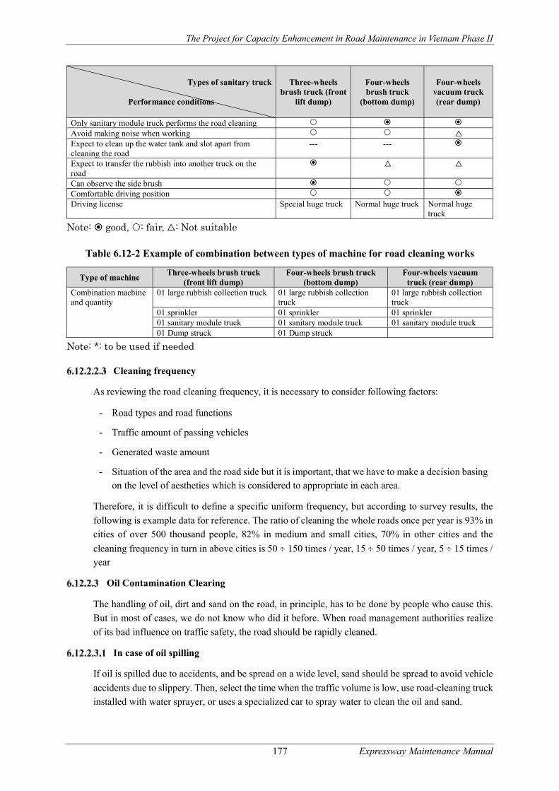
The Project for Capacity Enhancement in Road Maintenance in Vietnam Phase II
177 Expressway Maintenance Manual
Types of sanitary truck
Performance conditions
Three-wheels brush truck (front
lift dump)
Four-wheels brush truck
(bottom dump)
Four-wheels vacuum truck (rear dump)
Only sanitary module truck performs the road cleaning Avoid making noise when working △ Expect to clean up the water tank and slot apart from cleaning the road
--- ---
Expect to transfer the rubbish into another truck on the road
△ △
Can observe the side brush Comfortable driving position Driving license Special huge truck Normal huge truck Normal huge
truck
Note: good, : fair, △: Not suitable
Table 6.12-2 Example of combination between types of machine for road cleaning works
Type of machine Three-wheels brush truck
(front lift dump) Four-wheels brush truck
(bottom dump) Four-wheels vacuum
truck (rear dump) Combination machine and quantity
01 large rubbish collection truck 01 large rubbish collection truck
01 large rubbish collection truck
01 sprinkler 01 sprinkler 01 sprinkler 01 sanitary module truck 01 sanitary module truck 01 sanitary module truck 01 Dump struck 01 Dump struck
Note: *: to be used if needed
Cleaning frequency
As reviewing the road cleaning frequency, it is necessary to consider following factors:
- Road types and road functions
- Traffic amount of passing vehicles
- Generated waste amount
- Situation of the area and the road side but it is important, that we have to make a decision basing on the level of aesthetics which is considered to appropriate in each area.
Therefore, it is difficult to define a specific uniform frequency, but according to survey results, the
following is example data for reference. The ratio of cleaning the whole roads once per year is 93% in
cities of over 500 thousand people, 82% in medium and small cities, 70% in other cities and the
cleaning frequency in turn in above cities is 50 150 times / year, 15 50 times / year, 5 15 times / year
Oil Contamination Clearing
The handling of oil, dirt and sand on the road, in principle, has to be done by people who cause this.
But in most of cases, we do not know who did it before. When road management authorities realize
of its bad influence on traffic safety, the road should be rapidly cleaned.
In case of oil spilling
If oil is spilled due to accidents, and be spread on a wide level, sand should be spread to avoid vehicle
accidents due to slippery. Then, select the time when the traffic volume is low, use road-cleaning truck
installed with water sprayer, or uses a specialized car to spray water to clean the oil and sand.
The Project for Capacity Enhancement in Road Maintenance in Vietnam Phase II
178 Expressway Maintenance Manual
In case of dirt, sand was poured into the street
In case the road is heavily contaminated by big amount of unidentified cars day by day with a small
amount of dirt, or sand, or garbage arising in nature, a road-cleaning truck installed with water sprayer,
or a specialized car to spray water to clean can be used.
The other cases
If chemical drugs spread over the road and have to use neutralized chemicals to handle, contact the
fire department to ask for treatment. Then, use a road-cleaning truck which is installed with water
sprayer, or a specialized car to spray water to clean pavement.
In the square, in front of the station or sidewalks paved colorful tile, appropriate cleaners should be
used.
Notes on washing the street
- Select the low traffic time to carry out cleaning the road, and always pay attention on vehicles
or structures. However, spilled oil due to accidents has to be handled immediately regardless of
the time.
- The collection of garbage in the region near gutter can be done easily. The gutters can be cleaned just after washing road surface.
- Consider carefully in terms of execution speed, spray pressure and water spray.
Traffic Control
Objectives
Objectives of traffic control is to ensure vehicle safety and worker’s safety during maintenance and
repair work by controlling traffic flow near road maintenance and repair sections.
Application of this Guideline
Traffic Control Guideline shall be applied to all works conducted on the expressways which need
traffic control for the purposes of road facility inspection, detailed survey, road routine maintenance,
disaster restoration, periodic maintenance and road investment project. The guideline stipulates the
standard methods of traffic control. However, road and traffic conditions may vary from location to
location, so that road operator is requested to flexibly apply this guideline and develop traffic control
plan in conformity with road and traffic conditions under consideration.
Law Observation
Maintenance and repair works conducted on the expressway in operation is danger not only to road
users but to maintenance staff in the field, so that Traffic control shall be implemented in conformity
with relevant regulations including laws, decrees, circulars and decisions associated with road and
traffic.
Planning of Traffic Control
The following are the key elements in planning traffic control methods, so that road operator is
requested to take them into consideration in the planning;
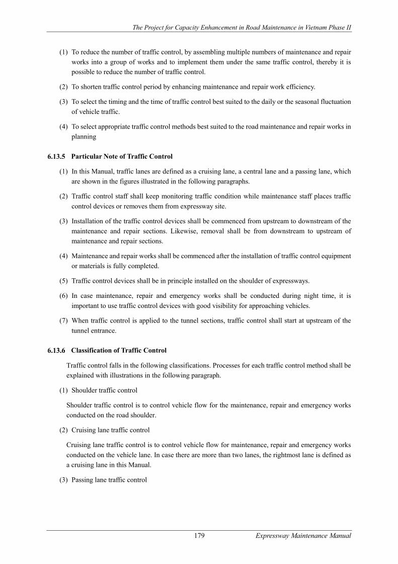
The Project for Capacity Enhancement in Road Maintenance in Vietnam Phase II
179 Expressway Maintenance Manual
(1) To reduce the number of traffic control, by assembling multiple numbers of maintenance and repair
works into a group of works and to implement them under the same traffic control, thereby it is
possible to reduce the number of traffic control.
(2) To shorten traffic control period by enhancing maintenance and repair work efficiency.
(3) To select the timing and the time of traffic control best suited to the daily or the seasonal fluctuation
of vehicle traffic.
(4) To select appropriate traffic control methods best suited to the road maintenance and repair works in
planning
Particular Note of Traffic Control
(1) In this Manual, traffic lanes are defined as a cruising lane, a central lane and a passing lane, which
are shown in the figures illustrated in the following paragraphs.
(2) Traffic control staff shall keep monitoring traffic condition while maintenance staff places traffic
control devices or removes them from expressway site.
(3) Installation of the traffic control devices shall be commenced from upstream to downstream of the
maintenance and repair sections. Likewise, removal shall be from downstream to upstream of
maintenance and repair sections.
(4) Maintenance and repair works shall be commenced after the installation of traffic control equipment
or materials is fully completed.
(5) Traffic control devices shall be in principle installed on the shoulder of expressways.
(6) In case maintenance, repair and emergency works shall be conducted during night time, it is
important to use traffic control devices with good visibility for approaching vehicles.
(7) When traffic control is applied to the tunnel sections, traffic control shall start at upstream of the
tunnel entrance.
Classification of Traffic Control
Traffic control falls in the following classifications. Processes for each traffic control method shall be
explained with illustrations in the following paragraph.
(1) Shoulder traffic control
Shoulder traffic control is to control vehicle flow for the maintenance, repair and emergency works
conducted on the road shoulder.
(2) Cruising lane traffic control
Cruising lane traffic control is to control vehicle flow for maintenance, repair and emergency works
conducted on the vehicle lane. In case there are more than two lanes, the rightmost lane is defined as
a cruising lane in this Manual.
(3) Passing lane traffic control
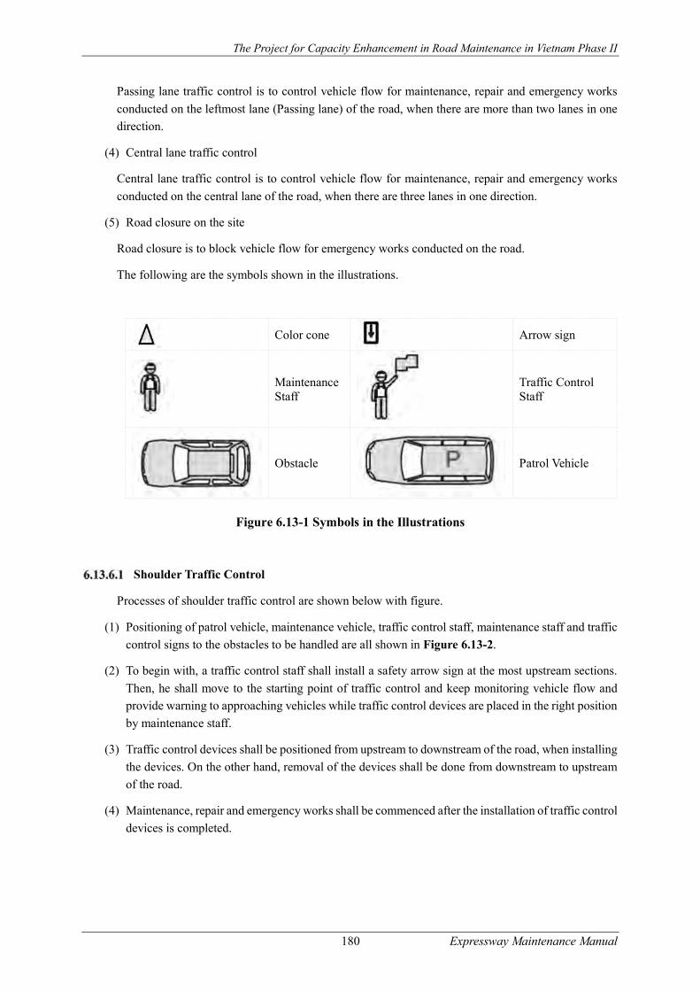
The Project for Capacity Enhancement in Road Maintenance in Vietnam Phase II
180 Expressway Maintenance Manual
Passing lane traffic control is to control vehicle flow for maintenance, repair and emergency works
conducted on the leftmost lane (Passing lane) of the road, when there are more than two lanes in one
direction.
(4) Central lane traffic control
Central lane traffic control is to control vehicle flow for maintenance, repair and emergency works
conducted on the central lane of the road, when there are three lanes in one direction.
(5) Road closure on the site
Road closure is to block vehicle flow for emergency works conducted on the road.
The following are the symbols shown in the illustrations.
Color cone
Arrow sign
Maintenance Staff
Traffic Control Staff
Obstacle
Patrol Vehicle
Figure 6.13-1 Symbols in the Illustrations
Shoulder Traffic Control
Processes of shoulder traffic control are shown below with figure.
(1) Positioning of patrol vehicle, maintenance vehicle, traffic control staff, maintenance staff and traffic
control signs to the obstacles to be handled are all shown in Figure 6.13-2.
(2) To begin with, a traffic control staff shall install a safety arrow sign at the most upstream sections.
Then, he shall move to the starting point of traffic control and keep monitoring vehicle flow and
provide warning to approaching vehicles while traffic control devices are placed in the right position
by maintenance staff.
(3) Traffic control devices shall be positioned from upstream to downstream of the road, when installing
the devices. On the other hand, removal of the devices shall be done from downstream to upstream
of the road.
(4) Maintenance, repair and emergency works shall be commenced after the installation of traffic control
devices is completed.
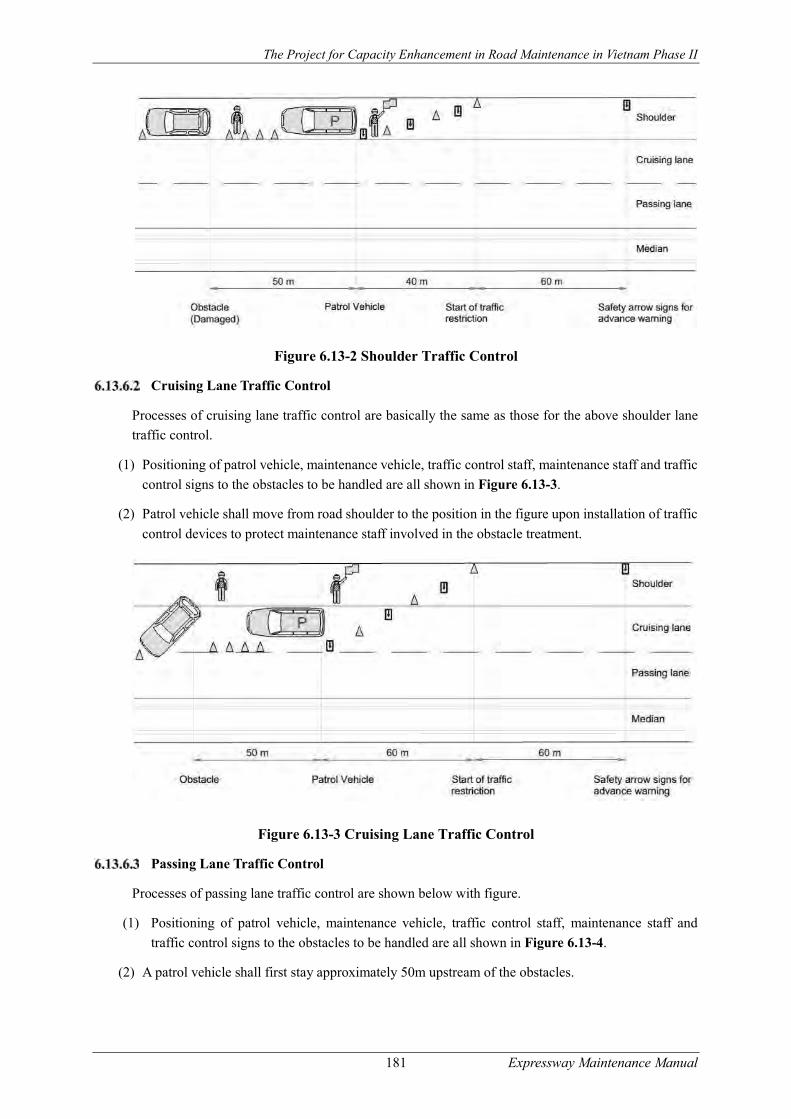
The Project for Capacity Enhancement in Road Maintenance in Vietnam Phase II
181 Expressway Maintenance Manual
Figure 6.13-2 Shoulder Traffic Control
Cruising Lane Traffic Control
Processes of cruising lane traffic control are basically the same as those for the above shoulder lane
traffic control.
(1) Positioning of patrol vehicle, maintenance vehicle, traffic control staff, maintenance staff and traffic
control signs to the obstacles to be handled are all shown in Figure 6.13-3.
(2) Patrol vehicle shall move from road shoulder to the position in the figure upon installation of traffic
control devices to protect maintenance staff involved in the obstacle treatment.
Figure 6.13-3 Cruising Lane Traffic Control
Passing Lane Traffic Control
Processes of passing lane traffic control are shown below with figure.
(1) Positioning of patrol vehicle, maintenance vehicle, traffic control staff, maintenance staff and
traffic control signs to the obstacles to be handled are all shown in Figure 6.13-4.
(2) A patrol vehicle shall first stay approximately 50m upstream of the obstacles.
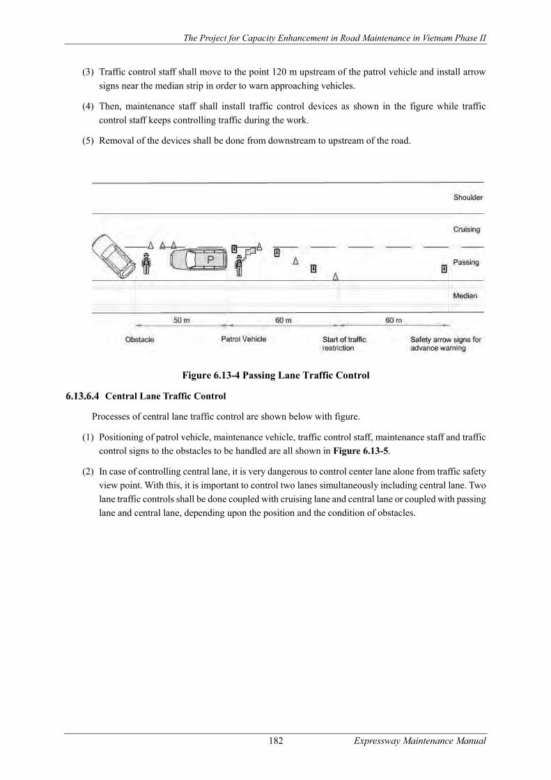
The Project for Capacity Enhancement in Road Maintenance in Vietnam Phase II
182 Expressway Maintenance Manual
(3) Traffic control staff shall move to the point 120 m upstream of the patrol vehicle and install arrow
signs near the median strip in order to warn approaching vehicles.
(4) Then, maintenance staff shall install traffic control devices as shown in the figure while traffic
control staff keeps controlling traffic during the work.
(5) Removal of the devices shall be done from downstream to upstream of the road.
Figure 6.13-4 Passing Lane Traffic Control
Central Lane Traffic Control
Processes of central lane traffic control are shown below with figure.
(1) Positioning of patrol vehicle, maintenance vehicle, traffic control staff, maintenance staff and traffic
control signs to the obstacles to be handled are all shown in Figure 6.13-5.
(2) In case of controlling central lane, it is very dangerous to control center lane alone from traffic safety
view point. With this, it is important to control two lanes simultaneously including central lane. Two
lane traffic controls shall be done coupled with cruising lane and central lane or coupled with passing
lane and central lane, depending upon the position and the condition of obstacles.
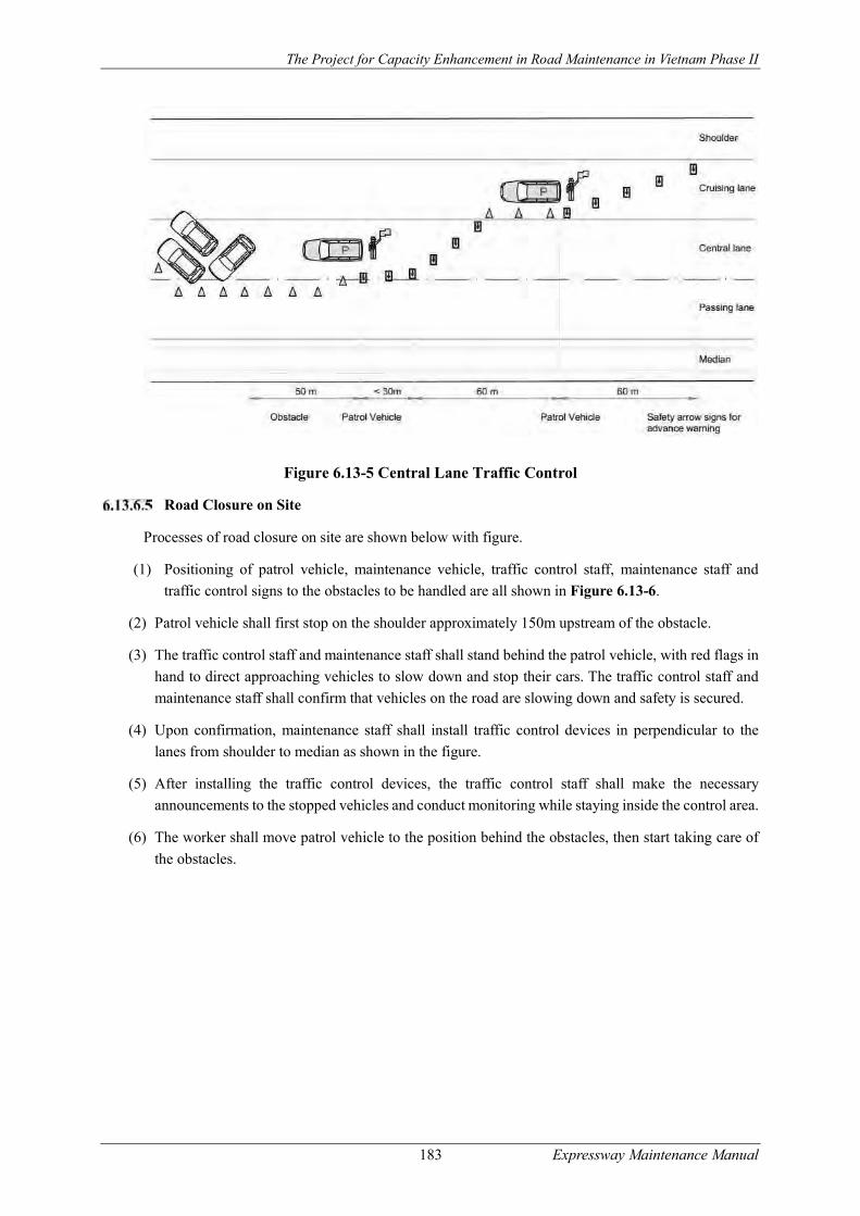
The Project for Capacity Enhancement in Road Maintenance in Vietnam Phase II
183 Expressway Maintenance Manual
Figure 6.13-5 Central Lane Traffic Control
Road Closure on Site
Processes of road closure on site are shown below with figure.
(1) Positioning of patrol vehicle, maintenance vehicle, traffic control staff, maintenance staff and
traffic control signs to the obstacles to be handled are all shown in Figure 6.13-6.
(2) Patrol vehicle shall first stop on the shoulder approximately 150m upstream of the obstacle.
(3) The traffic control staff and maintenance staff shall stand behind the patrol vehicle, with red flags in
hand to direct approaching vehicles to slow down and stop their cars. The traffic control staff and
maintenance staff shall confirm that vehicles on the road are slowing down and safety is secured.
(4) Upon confirmation, maintenance staff shall install traffic control devices in perpendicular to the
lanes from shoulder to median as shown in the figure.
(5) After installing the traffic control devices, the traffic control staff shall make the necessary
announcements to the stopped vehicles and conduct monitoring while staying inside the control area.
(6) The worker shall move patrol vehicle to the position behind the obstacles, then start taking care of
the obstacles.
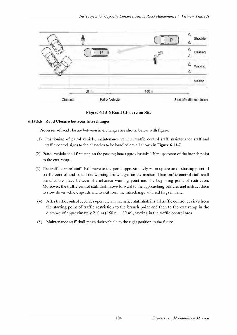
The Project for Capacity Enhancement in Road Maintenance in Vietnam Phase II
184 Expressway Maintenance Manual
Figure 6.13-6 Road Closure on Site
Road Closure between Interchanges
Processes of road closure between interchanges are shown below with figure.
(1) Positioning of patrol vehicle, maintenance vehicle, traffic control staff, maintenance staff and
traffic control signs to the obstacles to be handled are all shown in Figure 6.13-7.
(2) Patrol vehicle shall first stop on the passing lane approximately 150m upstream of the branch point
to the exit ramp.
(3) The traffic control staff shall move to the point approximately 60 m upstream of starting point of traffic control and install the warning arrow signs on the median. Then traffic control staff shall
stand at the place between the advance warning point and the beginning point of restriction.
Moreover, the traffic control staff shall move forward to the approaching vehicles and instruct them
to slow down vehicle speeds and to exit from the interchange with red flags in hand.
(4) After traffic control becomes operable, maintenance staff shall install traffic control devices from the starting point of traffic restriction to the branch point and then to the exit ramp in the distance of approximately 210 m (150 m + 60 m), staying in the traffic control area.
(5) Maintenance staff shall move their vehicle to the right position in the figure.
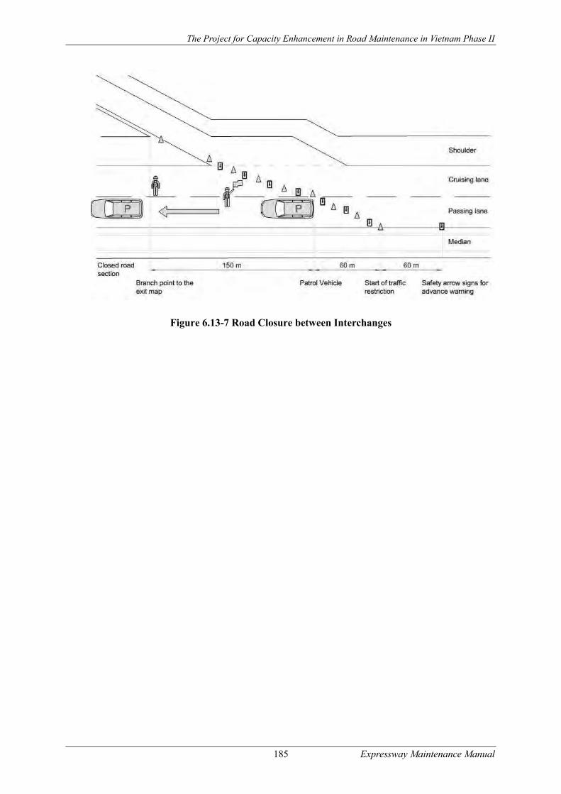
The Project for Capacity Enhancement in Road Maintenance in Vietnam Phase II
185 Expressway Maintenance Manual
Figure 6.13-7 Road Closure between Interchanges
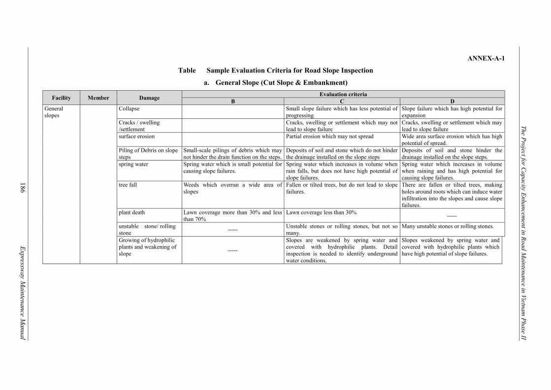
The Project for C
apacity Enhancem
ent in Road M
aintenance in Vietnam P
hase II
186
E
xpressway M
aintenance Manual
ANNEX-A-1
Table Sample Evaluation Criteria for Road Slope Inspection
a. General Slope (Cut Slope & Embankment)
Facility Member Damage Evaluation criteria
B C D General slopes
Collapse Small slope failure which has less potential of progressing
Slope failure which has high potential for expansion
Cracks / swelling /settlement
Cracks, swelling or settlement which may not lead to slope failure
Cracks, swelling or settlement which may lead to slope failure
surface erosion Partial erosion which may not spread Wide area surface erosion which has high potential of spread.
Piling of Debris on slope steps
Small-scale pilings of debris which may not hinder the drain function on the steps.
Deposits of soil and stone which do not hinder the drainage installed on the slope steps
Deposits of soil and stone hinder the drainage installed on the slope steps.
spring water Spring water which is small potential for causing slope failures.
Spring water which increases in volume when rain falls, but does not have high potential of slope failures.
Spring water which increases in volume when raining and has high potential for causing slope failures.
tree fall Weeds which overran a wide area of slopes
Fallen or tilted trees, but do not lead to slope failures.
There are fallen or tilted trees, making holes around roots which can induce water infiltration into the slopes and cause slope failures.
plant death Lawn coverage more than 30% and less than 70%
Lawn coverage less than 30% -----
unstable stone/ rolling stone
----- Unstable stones or rolling stones, but not so many.
Many unstable stones or rolling stones.
Growing of hydrophilic plants and weakening of slope
-----
Slopes are weakened by spring water and covered with hydrophilic plants. Detail inspection is needed to identify underground water conditions.
Slopes weakened by spring water and covered with hydrophilic plants which have high potential of slope failures.
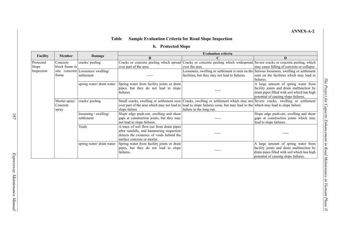
The Project for C
apacity Enhancem
ent in Road M
aintenance in Vietnam P
hase II
187
E
xpressway M
aintenance Manual
ANNEX-A-2
Table Sample Evaluation Criteria for Road Slope Inspection
b. Protected Slope
Facility Member Damage Evaluation criteria
B C D Protected Slope Inspection
Concrete block frame in situ /concrete frame
cracks/ peeling Cracks or concrete peeling which spread over part of the area.
Cracks or concrete peeling which widespread over the area.
Severe cracks or concrete peeling, which may cause falling of concrete or collapse
Looseness/ swelling/ settlement -----
Looseness, swelling or settlement is seen on the facilities, but they may not lead to failures.
Serious looseness, swelling or settlement seen on the facilities which may lead to failures.
spring water/ drain water Spring water from facility joints or drain pipes, but they do not lead to slope failures.
-----
A large amount of spring water from facility joints and drain malfunction by drain pipes filled with soil which has high potential of causing slope failures.
Mortar spray/ Concrete spray
cracks/ peeling Small cracks, swelling or settlement seen over part of the area which may not lead to slope failure
Cracks, swelling or settlement which may not lead to slope failures soon, but may lead to the failure in the long run.
Severe cracks, swelling or settlement which may lead to slope failure
loosening / swelling/ settlement
Slope edge push-out, swelling and shear gaps at construction joints, but they may not lead to slope failures.
----- Slope edge push-out, swelling and shear gaps at construction joints which may lead to slope failures.
Voids A trace of soil flow-out from drain pipes after rainfalls, and hammering inspection detects the existence of voids behind the surface concrete or mortar.
----- -----
spring water/ drain water Spring water from facility joints or drain pipes, but they do not lead to slope failures.
-----
A large amount of spring water from facility joints and drain malfunction by drain pipes filled with soil which has high potential of causing slope failures.

The Project for C
apacity Enhancem
ent in Road M
aintenance in Vietnam P
hase II
188
E
xpressway M
aintenance Manual
ANNEX-B
Table Sample Evaluation Criteria for Road Drainage System
Facility Member Damage Evaluation criteria
B C D Slope drainage systems
Slope shoulder drainage/ Slope step
drainage Vertical
drainage Catch basins
Damages to drainage body -----
Medium damages of drainage systems which hinder drain functions.
Heavy damage of drainage systems which cause water overflow and rain infiltration
Improper drainage joints Small water leakage which does not lead to slope failures.
Heavy damage of drainage joints which cause water leakage from joints and rain infiltration into slopes
Debris/ soil accumulation Limited or partial piling of soils and debris
Piling of soil and debris which hinder drain functions.
Large piling of soil and debris
Hindrance of drain function by weeds
Small hindrance of drain functions
Heavy hindrance of drain function by weed
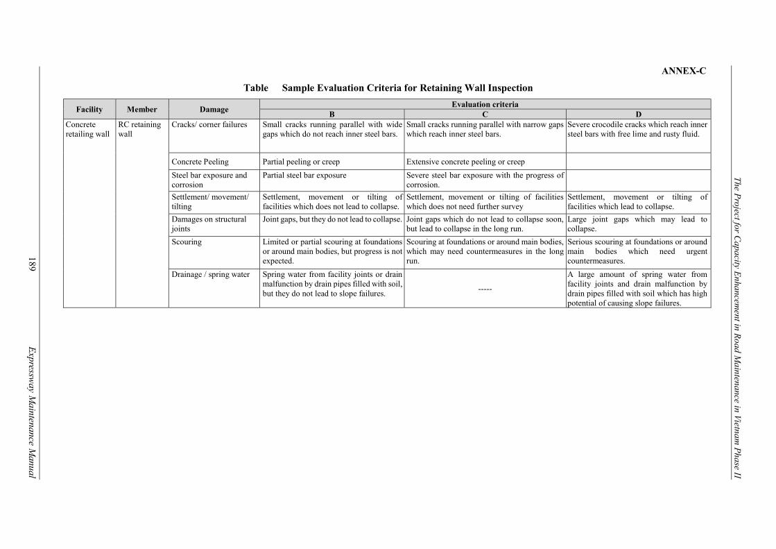
The Project for C
apacity Enhancem
ent in Road M
aintenance in Vietnam P
hase II
189
E
xpressway M
aintenance Manual
ANNEX-C
Table Sample Evaluation Criteria for Retaining Wall Inspection
Facility Member Damage Evaluation criteria
B C D Concrete retailing wall
RC retaining wall
Cracks/ corner failures Small cracks running parallel with wide gaps which do not reach inner steel bars.
Small cracks running parallel with narrow gaps which reach inner steel bars.
Severe crocodile cracks which reach inner steel bars with free lime and rusty fluid.
Concrete Peeling Partial peeling or creep Extensive concrete peeling or creep
Steel bar exposure and corrosion
Partial steel bar exposure Severe steel bar exposure with the progress of corrosion.
Settlement/ movement/ tilting
Settlement, movement or tilting of facilities which does not lead to collapse.
Settlement, movement or tilting of facilities which does not need further survey
Settlement, movement or tilting of facilities which lead to collapse.
Damages on structural joints
Joint gaps, but they do not lead to collapse. Joint gaps which do not lead to collapse soon, but lead to collapse in the long run.
Large joint gaps which may lead to collapse.
Scouring Limited or partial scouring at foundations or around main bodies, but progress is not expected.
Scouring at foundations or around main bodies, which may need countermeasures in the long run.
Serious scouring at foundations or around main bodies which need urgent countermeasures.
Drainage / spring water Spring water from facility joints or drain malfunction by drain pipes filled with soil, but they do not lead to slope failures.
-----
A large amount of spring water from facility joints and drain malfunction by drain pipes filled with soil which has high potential of causing slope failures.

The Project for C
apacity Enhancem
ent in Road M
aintenance in Vietnam P
hase II
190
E
xpressway M
aintenance Manual
ANNEX-D-1 Table Sample Evaluation Criteria for Road Pavement Inspection
(i) Asphalt Concrete Pavement
Structure Member Sort of damage Evaluation Criteria
B C D Road Pavement Asphalt
pavement
Pot holes/ Peeling/ Depressions
----- 20 cm–40cm in diameter or 30 mm-40 mm in depth
Over 40 cm in diameter or Over 40 mm in depth.
Crack ratio 10% - 30% 30% - 40% Over 40 %.
Rutting Depth 10mm - 30 mm 30mm - 40mm Over 40 mm
IRI 2 – 4 mm/m 4 – 6 mm/m Over 6 mm/m
Edge Break ----- Surface level difference 10 mm – 30 mm
Pavement width less than design lane width or Surface level difference over 30mm.
Bump in pavement surface
-----
10 mm - 20 mm in depth at the connection with bridges 10mm - 30mm in depth at crossing structures or cut/fill transition points
Over 20mm at the connections with bridges Over 30 mm at crossing structures or cut/fill transition points.
Skid Resistance ----- 0.25 ì (V) - 0.3 i(V). Over ì (V) 0.25.
(ii) Bituminous Surface Treatment
Structure Member Sort of damage Evaluation Criteria
B C D Road Pavement
Bituminous surface treatment
Pot holes/ Peeling/ Depressions
Less than 20 cm in diameter or 30 mm in depth
20 cm–40cm in diameter or 30 mm-40 mm in depth
Over 40 cm in diameter or Over 40 mm in depth.
Crack ratio 10% - 40% 40% - 50% Over 50 %.
Rutting Depth 10mm - 40 mm 40mm - 50mm Over 50 mm
IRI 4 – 6 mm/m 6 – 8 mm/m Over 8 mm/m
Edge Break Surface level difference 10 mm – 30 mm
Pavement width less than design lane width or Surface level difference over 30mm.
Bump in pavement surface
-----
10 mm - 20 mm in depth at the connection with bridges and at joints between slabs 10mm - 30mm in depth at crossing structures or cut/fill transition points
Over 20mm at the connections with bridges and at joints between slabs. Over 30 mm at crossing structures or cut/fill transition points.
Skid Resistance ----- 0.25 ì (V) - 0.3 i(V). Over ì (V) 0.25.

The Project for C
apacity Enhancem
ent in Road M
aintenance in Vietnam P
hase II
191
E
xpressway M
aintenance Manual
ANNEX-D-2
Table Sample Evaluation Criteria for Road Pavement Inspection
(iii) Cement Concrete Pavement
Structure Member Sort of damage Evaluation Criteria
B C D Road Pavement
Concrete pavement
Crack ratio ----- 30% - 40% Over 40 %.
IRI ----- ----- Over 4 mm/m
Bump in pavement surface
-----
10 mm - 20 mm in depth at the connection with bridges 10mm - 30mm in depth at crossing structures or cut/fill transition points
Over 20mm at the connections with bridges Over 30 mm at crossing structures or cut/fill transition points.
Slab joint seal -----
Damaged but water infiltration is not observed
Damaged and water infiltration observed
Skid Resistance ----- 0.25 ì (V) - 0.3 i(V). Over ì (V) 0.25.
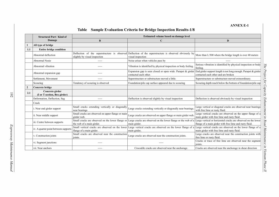
The Project for C
apacity Enhancem
ent in Road M
aintenance in Vietnam P
hase II
192
E
xpressway M
aintenance Manual
ANNEX E-1 Table Sample Evaluation Criteria for Bridge Inspection Results-1/8
Structural Part / Kind of Damage
Estimated volume based on damage level
B C D
1 All type of bridge
1.1 Entire bridge condition
Abnormal deflection Deflection of the superstructure is observed slightly by visual inspection
Deflection of the superstructure is observed obviously by visual inspection
More than L/500 where the bridge length is over 40 meters
Abnormal Nosie ----- Noise arises when vehicles pass by -----
Abnormal vibration ----- Vibration is identified by physical inspection or body feeling. Serious vibration is identified by physical inspection or body feeling.
Abnormal expansion gap ----- Expansion gap is seen closed or open wide. Parapet & girder contacted each other.
End girder support length is not long enough. Parapet & girder contacted each other and are broken
Settlement, Movement ----- Superstructure or substructure moved a little. Superstructure or substructure moved extraordinary.
Scouring Tendency of scouring is observed Foundation/pile cap surface appeared due to scouring Scouring depth reach below the bottom of foundation/pile cap
2 Concrete bridge
2.1 Concrete girder
(I or T section, Box girder)
Deformation, Deflection, Sag ----- Deflection is observed slightly by visual inspection Deflection is observed obviously by visual inspection
Crack
i. Near end girder support Small cracks extending vertically or diagonally near bearings
Large cracks extending vertically or diagonally near bearings. Large vertical or diagonal cracks are observed near bearings with free lime or rusty fluid.
ii. Near middle support Small cracks are observed on upper flange or main girder web.
Large cracks are observed on upper flange or main girder web. Large vertical cracks are observed on the upper flange of a main girder with free lime and rusty fluid.
iii. Centre between supports Small cracks are observed on the lower flange or the web of a main girder.
Large cracks are observed on the lower flange or the web of a main girder.
Large vertical or horizontal cracks are observed on the lower flange of a main girder with free lime and rusty fluid.
iv. A quarter point between supports Small vertical cracks are observed on the lower flange of a main girder.
Large vertical cracks are observed on the lower flange of a main girder,
Large vertical cracks are observed on the lower flange of a main girder with free lime and rusty fluid.
v. Construction joints Small cracks are observed near the construction joints.
Large cracks are observed near the construction joints. Large cracks are observed near the construction joints with free lime or rusty fluid.
vi. Segment junctions ----- ----- Cracks or trace of free lime are observed near the segment joints.
vii. Near anchors ----- Crocodile cracks are observed near the anchorage. Cracks are observed near the anchorage in shear direction

The Project for C
apacity Enhancem
ent in Road M
aintenance in Vietnam P
hase II
193
E
xpressway M
aintenance Manual
ANNEX-E-2 Table Sample Evaluation Criteria for Bridge Inspection Results-2/8
Structural Part / Kind of Damage
Estimated volume based on damage level
B C D
viii. Notch of a girder ----- ----- Diagonal cracks are observed near the notch of a girder.
Peeling, Spalling, Creep Partial peeling is observed. Wide concrete peeling is observed or peeling spreads. Wide concrete peeling, spalling or creep with serious corroded rebar is observed
Rebars exposure, Corrosion Rebar exposure is observed partially Rebar exposure is observed and rusting of rebars is progressing -----
Water leakage, Puddling Water leakage or puddles is observed in rainy days. Water leakage or puddles is observed regardless of weather. -----
Free lime Free lime is observed, but no serious Serious free lime is detected which seemingly from corroded steel members
-----
Rusty fluid Some rusty fluid is observed Serious rusty fluid is observed, in particular, from rebars or PC cables. -----
Deterioration, Discoloration Partial change in color is observed Concrete changes its color on the surface near cracks -----
Honey comb, Void Some of honey-combs and voids are observed, but not many
Many large honey-combs and voids are observed -----
Chemical attacks Tendency of chemical attack effects is observed Chemical attacks and serious rebars corrosion are observed -----
2.2 Concrete cross beam, Diaphragm
Crack Cracks at long intervals do not reached to rebar depth
Small cracks at small intervals reached to rebar depth -----
Peeling, Spalling, Creep Partial peeling, spalling or creep is observed. Wide concrete peeling, spalling or creep is observed -----
Rebars exposure, Corrosion Rebar exposure is observed partially Rebar exposure is observed and rusting of rebars progresses -----
Water leakage, Puddling Water leakage or puddles is observed in rainy days. Water leakage or puddles is observed regardless of weather. -----
Free lime Free lime is observed, but not serious Serious free lime is observed which seemingly from corroded steel members. -----
Rusty fluid Some rusty fluid is observed Serious rusty fluid is observed, in particular, from anchors of steel members or PC cables. -----
Deterioration, Discoloration Partial change in concrete color is observed Concrete changes its color on the surface near cracks -----
Honey comb, Void Some of honey-combs and voids are observed, but not many
Many large honey-combs and voids are observed -----
Chemical attacks Tendency of chemical attack effects is observed Chemical attacks and serious rebars corrosion are observed -----

The Project for C
apacity Enhancem
ent in Road M
aintenance in Vietnam P
hase II
194
E
xpressway M
aintenance Manual
ANNEX-E-3 Table Sample Evaluation Criteria for Bridge Inspection Results-3/8
Structural Part / Kind of Damage
Estimated volume based on damage level
B C D
2.3 Concrete deck slab
Crack Longitudinal and transverse cracks are observed Cracks develops to crocodile cracks Crocodile cracks cause spalling
Peeling, Spalling, Creep Small scale concrete peeling, spalling or creep is observed.
Wide concrete peeling, spalling or creep is observed -----
Rebars exposure, Corrosion Partial rebars exposure is observed. Rebar exposure is observed with progress of corrosion -----
Water leakage, Puddling Water leakage or puddles is observed in rainy days.
Water leakage or puddles is observed regardless of weather. -----
Free lime Free lime running in one direction is detected with color change
Free lime running in two directions is observed with color change.
Large extent of free lime running in two directions with color change is observed.
Rusty fluid Some rusty fluid is observed Severe rusty fluid is observed. -----
Deterioration, Discoloration Concrete surface has changed its color in limited areas.
Concrete surface has changed its color near cracks -----
Honey comb, Void Some honey combs, voids are observed. Large honey combs, voids are observed Voids or holes due to crocodile crack are observed
Chemical attacks Tendency of chemical attack effects is observed Chemical attacks and serious rebars corrosion are observed -----
3 Steel bridge
3.1 Steel girder, Truss member, Arch member and Steel pier
Deterioration of paint Cracks, peeling, swollen or rust are observed in limited area.
Cracks, peeling, swelling or rust are observed over a wide area
-----
Corrosion There is one missing or loosen rivets or bolt-nuts observed on one connection plate
Reduction in steel plate thickness is observed due to corrosion
Corrosion on the main members develops significantly and gives significant negative impacts on strength of the structure
Loosen and fallen of rivets, bolt-nuts, and HTBs
There is one missing or loosen rivets or bolt-nuts observed on one connection plate
More than 2 rivets or bolt-nuts are missing or loosen on one connection plate
-----
Crack
i. Welding portions on sole plates ----- Cracks appear Cracks reached web plates
ii. Girder end where cross section
of web plate changes ----- Cracks appear Cracks reached web plates
iii. Welding portions with vertical
stiffeners ----- Cracks appear -----
iv. Welding portions with gusset
plates ----- Paint cracks appear Cracks progress onto web plates
v. Butt welding portions on lower
flanges ----- Paint cracks appear Cracks appear
vi. Welding portions with steel
deck plates ----- Cracks appear Cracks extend over two thirds of welding length

The Project for C
apacity Enhancem
ent in Road M
aintenance in Vietnam P
hase II
195
E
xpressway M
aintenance Manual
ANNEX-E-4
Table Sample Evaluation Criteria for Bridge Inspection Results-4/8
Structural Part / Kind of Damage
Estimated volume based on damage level
B C D
vii. Welding portions between
vertical stiffeners and steel deck plates
----- Cracks appear Cracks appear on steel deck plates
viii. End of stringers where cross
section of the girder changes ----- Cracks appear
Cracks progress on the stringer web extending in the direction that could break the stringer
ix. Base of vertical members on the
arch ribs ----- There is potential of breaking vertical members Cracks extend to arch chord or to the stiffeners of the girder
x. Welding portions on shoe base
plates ----- Cracks appear -----
xi. Corners of steel piers ----- Cracks appear Cracks appear and may progress
xii. Others ----- Cracks appear Other locations where large cracks are found
Deformation and buckling Slight deformation or buckling arises Deformation or buckling arises and brigs a negative impacts on strength of the structure.
Significant deformation or buckling arises and bring significant negative impacts on strength of the structure.
Water leakage, Puddling Water leakage or puddles is sometimes seen on rainy days
Water leakage or puddle is seen anytime regardless of weather conditions
-----
3.2 Steel Cross beam, Stringer,
Diaphragm
Deterioration of paint Cracks, peeling, swollen or rust are observed in limited area.
Cracks, peeling, swelling or rust are observed over a wide area -----
Corrosion Reduction in steel plate thickness is found due to corrosion
Corrosion on the members develops significantly and causes significant negative impacts on the strength of the structure
Severe rust on over 50% of length of the member
Loosen and fallen of rivets, bolt-nuts, and HTBs
There is one missing or loosen rivets or bolt-nuts observed on one connection plate
More than 2 rivets or bolt-nuts are missing or loosen on one connection plate
Crack ----- Some cracking Severe cracking
Deformation and buckling ----- Slight deformation or buckling arises Significant deformation or buckling arises and to be a significant negative impacts on strength of the structure.
Water leakage, Puddling Water leakage or puddles is sometimes seen on rainy days
Water leakage or puddle is seen anytime regardless of weather conditions
-----
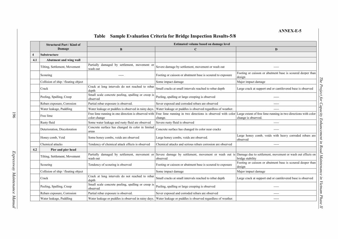
The Project for C
apacity Enhancem
ent in Road M
aintenance in Vietnam P
hase II
196
E
xpressway M
aintenance Manual
ANNEX-E-5 Table Sample Evaluation Criteria for Bridge Inspection Results-5/8
Structural Part / Kind of Damage
Estimated volume based on damage level
B C D
4 Substructure
4.1 Abutment and wing wall
Tilting, Settlement, Movement Partially damaged by settlement, movement or wash out
Severe damage by settlement, movement or wash out -----
Scouring ----- Footing or caisson or abutment base is scoured to exposure Footing or caisson or abutment base is scoured deeper than design
Collision of ship / floating object Some impact damage Major impact damage
Crack Crack at long intervals do not reached to rebar depth
Small cracks at small intervals reached to rebar depth Large crack at support end or cantilevered base is observed
Peeling, Spalling, Creep Small scale concrete peeling, spalling or creep is observed
Peeling, spalling or large creeping is observed -----
Rebars exposure, Corrosion Partial rebar exposure is observed. Sever exposed and corroded rebars are observed -----
Water leakage, Puddling Water leakage or puddles is observed in rainy days. Water leakage or puddles is observed regardless of weather. -----
Free lime Free lime running in one direction is observed with color change
Free lime running in two directions is observed with color change.
Large extent of free lime running in two directions with color change is observed.
Rusty fluid Some water leakage and rusty fluid are observed Severe rusty fluid is observed -----
Deterioration, Discoloration Concrete surface has changed its color in limited areas
Concrete surface has changed its color near cracks -----
Honey comb, Void Some honey combs, voids are observed Large honey combs, voids are observed. Large honey comb, voids with heavy corroded rebars are observed
Chemical attacks Tendency of chemical attack effects is observed Chemical attacks and serious rebars corrosion are observed -----
4.2 Pier and pier head
Tilting, Settlement, Movement Partially damaged by settlement, movement or wash out
Severe damage by settlement, movement or wash out is observed
Damage due to settlement, movement or wash out effects on bridge stability
Scouring Tendency of scouring is observed Footing or caisson or abutment base is scoured to exposure Footing or caisson or abutment base is scoured deeper than design
Collision of ship / floating object Some impact damage Major impact damage
Crack Crack at long intervals do not reached to rebar depth
Small cracks at small intervals reached to rebar depth Large crack at support end or cantilevered base is observed
Peeling, Spalling, Creep Small scale concrete peeling, spalling or creep is observed
Peeling, spalling or large creeping is observed -----
Rebars exposure, Corrosion Partial rebar exposure is observed. Sever exposed and corroded rebars are observed -----
Water leakage, Puddling Water leakage or puddles is observed in rainy days. Water leakage or puddles is observed regardless of weather. -----

The Project for C
apacity Enhancem
ent in Road M
aintenance in Vietnam P
hase II
197
E
xpressway M
aintenance Manual
ANNEX-E-6
Table.. Sample Evaluation Criteria for Bridge Inspection Results-6/8
Structural Part / Kind of
Damage
Estimated volume based on damage level
B C D
Free lime Free lime running in one direction is observed with
color change
Free lime running in two directions is observed with color
change.
Large extent of free lime running in two directions with color
change is observed.
Rusty fluid Some water leakage and rusty fluid are observed Severe rusty fluid is observed -----
Deterioration, Discoloration Concrete surface has changed its color in limited
areas Concrete surface has changed its color near cracks -----
Honey comb, Void Some honey combs, voids are observed Large honey combs, voids are observed. Large honey comb, voids with heavy corroded rebars are
observed
Chemical attacks Tendency of chemical attack effects is observed Chemical attacks and serious rebars corrosion are observed -----
4.3 Foundation
(Footing, Pile cap, Pile)
Tilting, Settlement, Movement Partially damaged by settlement, movement or
wash out Severe damage by settlement, movement or wash out
Damage due to settlement, movement or wash out effects on
bridge stability
Scouring Tendency of scouring is observed Footing or caisson or abutment base is scoured to exposure Footing or caisson or abutment base is scoured deeper than
design
Collision of ship and floating object Some impact damage Major impact damage
Crack Crack at long intervals do not reached to rebar
depth Small cracks at small intervals reached to rebar depth Large crack at support end or cantilevered base is observed
Peeling, Spalling, Creep Small scale concrete peeling, spalling or creep is
observed Peeling, spalling or large creeping is observed -----
Rebars exposure, Corrosion Partial rebar exposure is observed. Sever exposed and corroded rebars are observed -----
Water leakage, Puddling Water leakage or puddles is observed in rainy days. Water leakage or puddles is observed regardless of weather. -----
Free lime Free lime running in one direction is observed with
color change
Free lime running in two directions is observed with color
change.
Large extent of free lime running in two directions with color
change is observed.
Rusty fluid Some water leakage and rusty fluid are observed Severe rusty fluid is observed -----
Deterioration, Discoloration Concrete surface has changed its color in limited
areas Concrete surface has changed its color near cracks -----
Honey comb, Void Some honey combs, voids are observed Large honey combs, voids are observed. Large honey comb, voids with heavy corroded rebars are
observed
Chemical attacks Tendency of chemical attack effects is observed Chemical attacks and serious rebars corrosion are observed -----
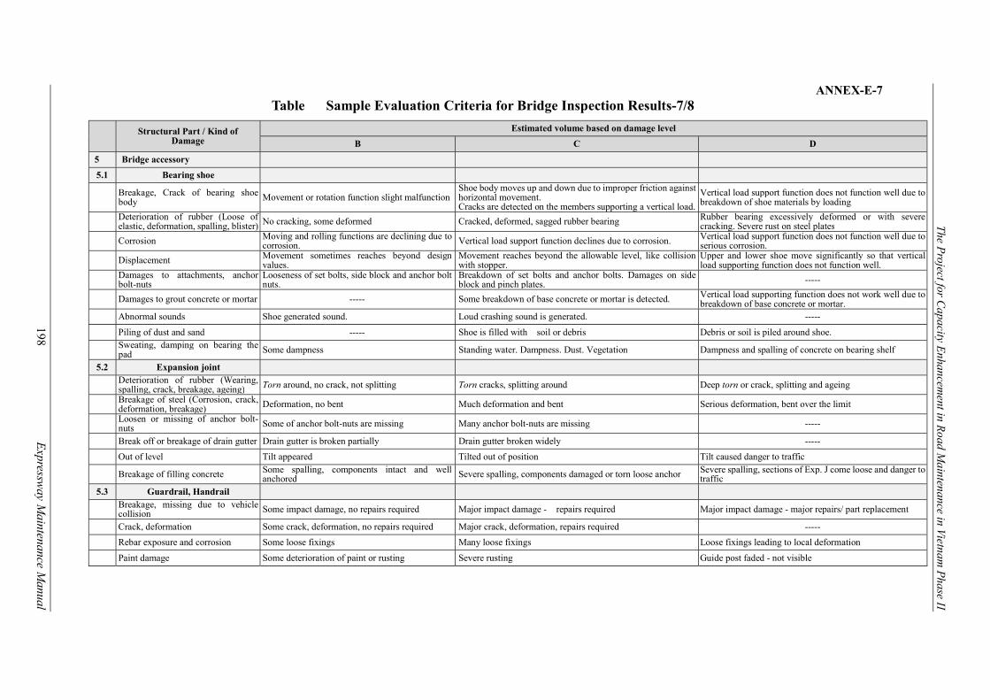
The Project for C
apacity Enhancem
ent in Road M
aintenance in Vietnam P
hase II
198
E
xpressway M
aintenance Manual
ANNEX-E-7 Table Sample Evaluation Criteria for Bridge Inspection Results-7/8
Structural Part / Kind of Damage
Estimated volume based on damage level
B C D
5 Bridge accessory
5.1 Bearing shoe
Breakage, Crack of bearing shoe body Movement or rotation function slight malfunction
Shoe body moves up and down due to improper friction against horizontal movement. Cracks are detected on the members supporting a vertical load.
Vertical load support function does not function well due to breakdown of shoe materials by loading
Deterioration of rubber (Loose of elastic, deformation, spalling, blister) No cracking, some deformed Cracked, deformed, sagged rubber bearing Rubber bearing excessively deformed or with severe
cracking. Severe rust on steel plates
Corrosion Moving and rolling functions are declining due to corrosion. Vertical load support function declines due to corrosion. Vertical load support function does not function well due to
serious corrosion.
Displacement Movement sometimes reaches beyond design values.
Movement reaches beyond the allowable level, like collision with stopper.
Upper and lower shoe move significantly so that vertical load supporting function does not function well.
Damages to attachments, anchor bolt-nuts
Looseness of set bolts, side block and anchor bolt nuts.
Breakdown of set bolts and anchor bolts. Damages on side block and pinch plates. -----
Damages to grout concrete or mortar ----- Some breakdown of base concrete or mortar is detected. Vertical load supporting function does not work well due to breakdown of base concrete or mortar.
Abnormal sounds Shoe generated sound. Loud crashing sound is generated. -----
Piling of dust and sand ----- Shoe is filled with soil or debris Debris or soil is piled around shoe.
Sweating, damping on bearing the pad Some dampness Standing water. Dampness. Dust. Vegetation Dampness and spalling of concrete on bearing shelf
5.2 Expansion joint
Deterioration of rubber (Wearing, spalling, crack, breakage, ageing) Torn around, no crack, not splitting Torn cracks, splitting around Deep torn or crack, splitting and ageing
Breakage of steel (Corrosion, crack, deformation, breakage) Deformation, no bent Much deformation and bent Serious deformation, bent over the limit
Loosen or missing of anchor bolt-nuts Some of anchor bolt-nuts are missing Many anchor bolt-nuts are missing -----
Break off or breakage of drain gutter Drain gutter is broken partially Drain gutter broken widely -----
Out of level Tilt appeared Tilted out of position Tilt caused danger to traffic
Breakage of filling concrete Some spalling, components intact and well anchored Severe spalling, components damaged or torn loose anchor Severe spalling, sections of Exp. J come loose and danger to
traffic 5.3 Guardrail, Handrail
Breakage, missing due to vehicle collision Some impact damage, no repairs required Major impact damage - repairs required Major impact damage - major repairs/ part replacement
Crack, deformation Some crack, deformation, no repairs required Major crack, deformation, repairs required -----
Rebar exposure and corrosion Some loose fixings Many loose fixings Loose fixings leading to local deformation
Paint damage Some deterioration of paint or rusting Severe rusting Guide post faded - not visible

The Project for C
apacity Enhancem
ent in Road M
aintenance in Vietnam P
hase II
199
E
xpressway M
aintenance Manual
ANNEX–E-8 Table … Sample Evaluation Criteria for Bridge Inspection Results 8/8
Structural Part / Kind of
Damage
Estimated volume based on damage level
B C D
5.4 Approach road
Settlement of road Settlement, movement - no signs of new
movements Major settlement, movement or deformation Settlement and deformation with scour and slip
Spalling/ Pothole on pavement Some spalling, no potholes Some spalling and potholes Major spalling, many potholes
Crack on pavement Some cracking Severe localized cracking Severe cracking all over
Settlement of foundation (Riprap,
gabion) ―
Tension crack in approach embankment slope. Some scour
but embankment slope stable
Fully developed slip failure. Major scour and unstable
embankment slope
5.5 Traffic control sign board
Missing pole / breakage /
deformation User Information signs missing Traffic prohibition sign missing Load limit for weak bridge signs missing
Affected by impact Some impact damage but signs intact and visible Major damage needing part replacement Damage needing total replacement
Unclear/ dirty Dirty but visible Only partially visible Faded or barely visible fully blocked from view
Obscured ― Partially blocked by vegetation Fully blocked from view
5.6 Lighting system
Warping of Lighting- post,
reinforced leaking Some rust on post Severe rust on or slightly bent post Rusted or bent post likely to fall on bridge deck
Break/ Missing lighting- post Functioning but not adequately Many lights not working Dangerously low lighting or electric shocks

The Project for C
apacity Enhancem
ent in Road M
aintenance in Vietnam P
hase II
200
E
xpressway M
aintenance Manual
ANNEX-F
Table Sample Evaluation Criteria for Tunnel Inspection
a. Concrete Lining
Facility Member Damage Evaluation criteria
B C D Tunnel Concrete
lining Cracks/Corner Drop Cracks (over 0.3 mm) or corner
drops, which are not progressing Cracks (over 0.3 mm) or corner drops which are progressing
Rapid progress of dense cracks or Tensile cracks and sheer cracks
Concrete Peeling/ Creep Thin concrete peeling or creeping Thick concrete peeling or creeping Large and wide scale Peeling or creeping Improper Construction joint Gaps or opening of construction
joints which are not progressing Gaps or opening of construction joints which are progressing
‘-----
Water leakage/ Free lime Some leaks and free lime (Water ooze out)
Some leaks and free lime (Water drop) Large-scale water leakage or free lime (Water gush out/flow out)
b. Tunnel Portal
Facility Member Damage Evaluation criteria
B C D Tunnel Portal Cracks/Corner Drop Cracks (over 0.3 mm) or corner drops,
which are not progressing Cracks (over 0.3 mm) or corner drops which are progressing
Rapid progress of dense cracks or Tensile cracks and sheer cracks
Concrete Peeling/ Creep Partial concrete peeling Wide concrete peeling or creeping Large and wide scale Peeling or creeping Settlement/movement/ tilting
‘----- Damage identifiable by visual inspection Damage identifiable by visual inspection
with cracks on the connection with tunnel body
Improper Construction joint Gaps or opening of construction joints which are not progressing
Gaps or opening of construction joints which are progressing.
‘-----
Scouring Small scouring Large scouring ‘----- Water leakage/ Free lime Some leaks and free lime Large-scale water leakage or free lime Large-scale water leakage or free lime
c. Inner Decoration Board & Tunnel Drainage System
Facility Member Damage Evaluation criteria
B C D Tunnel Inner
decoration board
Damage on the board ‘----- Partial cracks and peeling Large-scale cracks and peelings Damage on the accessories
‘----- Damages on accessories, but do not lead to the falling of decoration board
Damages on accessories which lead to the falling of decoration board
Drainage system
Damage on the drainage system
‘----- Degradation of drain function
Heavy damage on the drain function
Piling of debris Small piling of debris, but no gradation of drain function
Degradation of drain function Heavy damage on the drain function
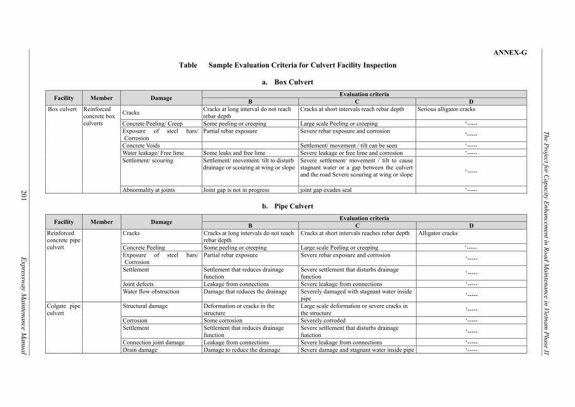
The Project for C
apacity Enhancem
ent in Road M
aintenance in Vietnam P
hase II
201
E
xpressway M
aintenance Manual
ANNEX-G
Table Sample Evaluation Criteria for Culvert Facility Inspection
a. Box Culvert
Facility Member Damage Evaluation criteria
B C D Box culvert Reinforced
concrete box culverts
Cracks Cracks at long interval do not reach rebar depth
Cracks at short intervals reach rebar depth Serious alligator cracks
Concrete Peeling/ Creep Some peeling or creeping Large scale Peeling or creeping ‘----- Exposure of steel bars/ Corrosion
Partial rebar exposure Severe rebar exposure and corrosion ‘-----
Concrete Voids Settlement/ movement / tilt can be seen ‘----- Water leakage/ Free lime Some leaks and free lime Severe leakage or free lime and corrosion ‘----- Settlement/ scouring Settlement/ movement/ tilt to disturb
drainage or scouring at wing or slope Severe settlement/ movement / tilt to cause stagnant water or a gap between the culvert and the road Severe scouring at wing or slope ‘-----
Abnormality at joints Joint gap is not in progress joint gap exudes seal ‘-----
b. Pipe Culvert
Facility Member Damage Evaluation criteria
B C D Reinforced concrete pipe culvert
Cracks Cracks at long intervals do not reach rebar depth
Cracks at short intervals reaches rebar depth Alligator cracks
Concrete Peeling Some peeling or creeping Large scale Peeling or creeping ‘----- Exposure of steel bars/ Corrosion
Partial rebar exposure Severe rebar exposure and corrosion ‘-----
Settlement Settlement that reduces drainage function
Severe settlement that disturbs drainage function
‘-----
Joint defects Leakage from connections Severe leakage from connections ‘----- Water flow obstruction Damage that reduces the drainage Severely damaged with stagnant water inside
pipe ‘-----
Colgate pipe culvert
Structural damage Deformation or cracks in the structure
Large scale deformation or severe cracks in the structure
‘-----
Corrosion Some corrosion Severely corroded ‘----- Settlement Settlement that reduces drainage
function Severe settlement that disturbs drainage function
‘-----
Connection joint damage Leakage from connections Severe leakage from connections ‘----- Drain damage Damage to reduce the drainage Severe damage and stagnant water inside pipe ‘-----
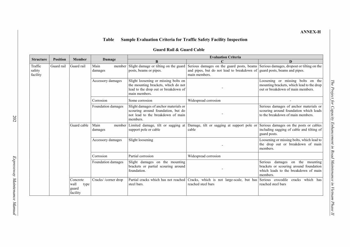
The Project for C
apacity Enhancem
ent in Road M
aintenance in Vietnam P
hase II
202
E
xpressway M
aintenance Manual
ANNEX-H
Table Sample Evaluation Criteria for Traffic Safety Facility Inspection
Guard Rail & Guard Cable
Structure Position Member Damage Evaluation Criteria
B C D Traffic safety facility
Guard rail Guard rail Main member damages
Slight damage or tilting on the guard posts, beams or pipes.
Serious damages on the guard posts, beams and pipes, but do not lead to breakdown of main members.
Serious damages, dropout or tilting on the guard posts, beams and pipes.
Accessory damages Slight loosening or missing bolts on the mounting brackets, which do not lead to the drop out or breakdown of main members.
-
Loosening or missing bolts on the mounting brackets, which lead to the drop out or breakdown of main members.
Corrosion Some corrosion Widespread corrosion -
Foundation damages Slight damages of anchor materials or scouring around foundation, but do not lead to the breakdown of main members.
-
Serious damages of anchor materials or scouring around foundation which leads to the breakdown of main members.
Guard cable Main member damages
Limited damage, tilt or sagging at support pole or cable
Damage, tilt or sagging at support pole or cable
Serious damages on the posts or cables including sagging of cable and tilting of guard posts.
Accessory damages Slight loosening
-
Loosening or missing bolts, which lead to the drop out or breakdown of main members.
Corrosion Partial corrosion Widespread corrosion
Foundation damages Slight damages on the mounting brackets or partial scouring around foundation. -
Serious damages on the mounting brackets or scouring around foundation which leads to the breakdown of main members.
Concrete wall type guard facility
Cracks/ /corner drop Partial cracks which has not reached steel bars.
Cracks, which is not large-scale, but has reached steel bars
Serious crocodile cracks which has reached steel bars

The Project for C
apacity Enhancem
ent in Road M
aintenance in Vietnam P
hase II
203
E
xpressway M
aintenance Manual
ANNEX-I
Table Sample Evaluation Criteria for Traffic Management Facility Inspection
Traffic Sign
Structure Position Member Damage Judge
B C D Traffic management facility
Traffic signs
Main member, accessories, foundation
Main member damages
Slight damages including deformation and breakage of sign boards or sign poles. However, information on the sign boards is still readable.
Damages including deformation, tilting and breakage of traffic signs. Also, it is hard to read information on the sign boards.
Severe damages including dropout of poles or sign boards, or deformation or tilting of traffic signs.
Accessory damages Slight damages including loosening of bolts or deformation of sign boards. However, they may not lead to dropout of sign boards or mounting brackets.
Damages on the mounting brackets, loosening or dropout of bolts and nuts which may cause dropout of sign boards or sign poles.
Corrosion Partial corrosion Widespread corrosion
Foundation Slight damages to the anchors or partial scouring around foundation.
Dropout of bolts, breakage, deformation of anchor material or scouring around foundation. Also, they may lead to serious breakdown of traffic signs.

The Project for C
apacity Enhancem
ent in Road M
aintenance in Vietnam P
hase II
204
E
xpressway M
aintenance Manual
ANNEX-J_S-1 INSPECTION DATA FORMAT (ROAD SLOPE FACILITY)
(*1): Refer to the relevant articles in the Inspection Guideline.
Inspection Facility (*1) Damage Type (*2)
General slopesProtected slopeRetaining wallsSlope drainage system
Serious damages- Cracks- Deformation- Swelling/settlement- ScouringDamages on drain system
Length(m)
width(cm)
Diameter(cm)
Depth(cm)
PieceVisual
observationLocationM emo
Photo withGPS Camera A, B, C, D, E M / M 2 / M 3 / Piece
NH00100 NORTHERN AREA RMB 1 RRMC236 1 0 NATIONAL HIGHWAY 1 3 0 3 120 D 2015 9 General slope Serious damages2nd cut slope from
roadsideNH00100-1 D Yes Bump repair work 120 * 0.3 * 0.08 Monitoring Sample Data
NH00100 NORTHERN AREA RMB 1 RRMC236 1 0 NATIONAL HIGHWAY 1 5 0 5 25 U 2015 9 Slope drainage systemDamages on drain
dystem25
1st cut slope fromroadside
NH00100-1 D -----Drainage repair
works25 m ----- Sample data
NoteFrom
(km,m)To
(km,m)Date
(yyyy/mm)
Loocation Information
DetailedInspection
SelectedRepair Work
Repair Work Volume MonitoringDamageRating
Damage Scale
Pavement Facility damage ConditionsKirometer Post
U/DID Route Name
BranchNumber
Geographical Area JurisdictionMaintenance
CompanyRoute
Number
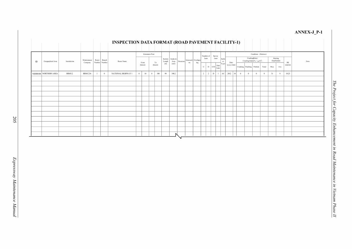
The Project for C
apacity Enhancem
ent in Road M
aintenance in Vietnam P
hase II
205
E
xpressway M
aintenance Manual
ANNEX-J_P-1
INSPECTION DATA FORMAT (ROAD PAVEMENT FACILITY-1)
U D U/DPathLane
Cracking Patching Pothole Total Max Ave
NH00100 NORTHERN AREA RRMU2 RRMC236 1 0 NATIONAL HIGHWAY 1 0 10 0 100 90 340.2 2 2 D 1 AC 2012 10 0 0 0 0 31 9 10.25
NoteFrom
(km,m)To
(km,m)Date
(yyyy/mm)
CrackingRatio/
Cracking Index(%/㎝/m2)
RuttingDepth(mm)
Kirometer Post
SectionLength
(m)
AnalysisArea(m2)
StructureIntersecti
onOverlapp
ing IRI (mm/m)
ID
Number ofLane
SurveyLane Surfa
ceType
Condition(Distress)
Geographical Area JurisdictionMaintenance
CompanyRoute
NumberBranch
NumberRoute Name

The Project for C
apacity Enhancem
ent in Road M
aintenance in Vietnam P
hase II
206
E
xpressway M
aintenance Manual
ANNEX-J_P-2 INSPECTION DATA FORMAT (ROAD PAVEMENT FACILITY-2)
(*1): Refer to the relevant articles in the Inspection Guideline.
Inspection Facility (*1) Damage Type (*1)
U/DPathLane
ACCCBituminous surfacetreatment (BST)Drainage system
PotholeEdge BreakBumpRoad Surface Drainage
Length(m)
width(cm)
Diameter(cm)
Depth(cm)
PieceVisual
observationLocationMemo
Photo withGPS Camera A, B, C, D, E M / M 2 / M 3 / Piece
NH00100 NORTHERN AREA RMB 1 RRMC236 1 0 NATIONAL HIGHWAY 1 3 0 3 120 D 1 AC 2015 9 AC Bump 30 8 ----- NH00100-1 D Yes Bump repair work 120 * 0.3 * 0.08 ----- Sample Data
NH00100 NORTHERN AREA RMB 1 RRMC236 1 0 NATIONAL HIGHWAY 1 10 0 --- --- D 1 AC 2015 9 BST Pothole 40 3 ----- NH00100-2 D Replacement 0.4 * 0.5 * 0.03 Monitoring Sample Data
NH00100 NORTHERN AREA RMB 1 RRMC236 1 0 NATIONAL HIGHWAY 1 13 20 --- --- D 1 AC 2015 9 Drainage system Drainage 25 ----- NH00100-3 C No Replacement 25 m ----- Sample Data
NH00100 NORTHERN AREA RMB 1 RRMC236 1 0 NATIONAL HIGHWAY 1 14 15 14 80 D 1 AC 2015 9 AC Pothole 20 1 Medien Drain NH00100-4 B ----- ----- ----- Monitoring Sample Data
NH00100 NORTHERN AREA RMB 1 RRMC236 1 0 NATIONAL HIGHWAY 1 18 25 18 275 D 1 AC 2015 9 CC Crack 250 0.2 0.1 Shoulder Drain NH00100-5 C ----- ----- 250 * 0.2 * 0.1 Monitoring Sample Data
ID Route NameBranchNumber
Geographical Area JurisdictionMaintenance
CompanyRoute
NumberNote
From(km,m)
To(km,m)
Date(yyyy/mm)
Kirometer Post
Loocation Information
SurveyLane
Surface
Type
DetailedInspection
SelectedRepair Work
Repair Work Volume MonitoringDamageRating
Pavement Facility damage Conditions
Damage Scale
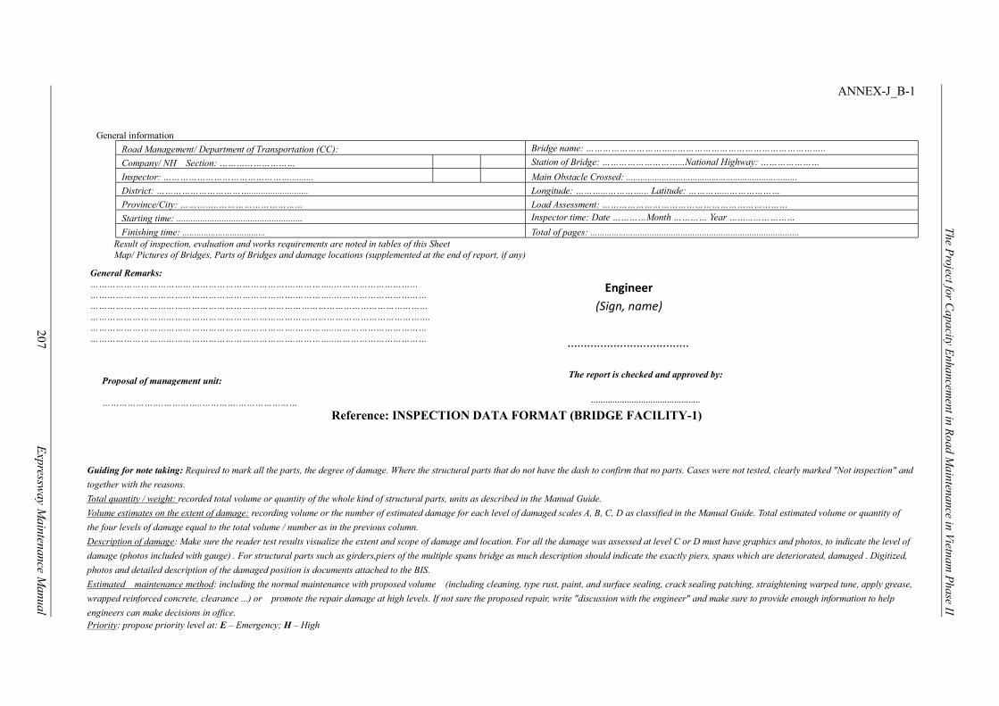
The Project for C
apacity Enhancem
ent in Road M
aintenance in Vietnam P
hase II
207
E
xpressway M
aintenance Manual
ANNEX-J_B-1
Reference: INSPECTION DATA FORMAT (BRIDGE FACILITY-1)
General information
Road Management/ Department of Transportation (CC): Bridge name: …………………………...……………………………………………..
Company/ NH Section: ……………………… Station of Bridge: ………………………...National Highway: …………………
Inspector: ……………………………………….......... Main Obstacle Crossed: ........................................................................
District: ……………………………......................... Longitude: ………...…………... Latitude: …………...………………
Province/City: …………..………………………… Load Assessment: …………………………………………………………
Starting time: ..................................................... Inspector time: Date …………Month ………… Year ……...……………
Finishing time: ................................... Total of pages: ........................................................................................ Result of inspection, evaluation and works requirements are noted in tables of this Sheet Map/ Pictures of Bridges, Parts of Bridges and damage locations (supplemented at the end of report, if any)
General Remarks: ……………………………………………………………….…………..………………………… ……………………………………………………………….…………..…………………………… ………………………………………………………………………………………………………… …………………………………………………………………………………………………………. ……………………………………………………………….…………..…………………………… ……………………………………………………………….…………..……………………………
Proposal of management unit: ………………….…………..………….…………………
Guiding for note taking: Required to mark all the parts, the degree of damage. Where the structural parts that do not have the dash to confirm that no parts. Cases were not tested, clearly marked "Not inspection" and
together with the reasons.
Total quantity / weight: recorded total volume or quantity of the whole kind of structural parts, units as described in the Manual Guide.
Volume estimates on the extent of damage: recording volume or the number of estimated damage for each level of damaged scales A, B, C, D as classified in the Manual Guide. Total estimated volume or quantity of
the four levels of damage equal to the total volume / number as in the previous column.
Description of damage: Make sure the reader test results visualize the extent and scope of damage and location. For all the damage was assessed at level C or D must have graphics and photos, to indicate the level of
damage (photos included with gauge) . For structural parts such as girders,piers of the multiple spans bridge as much description should indicate the exactly piers, spans which are deteriorated, damaged . Digitized,
photos and detailed description of the damaged position is documents attached to the BIS.
Estimated maintenance method: including the normal maintenance with proposed volume (including cleaning, type rust, paint, and surface sealing, crack sealing patching, straightening warped tune, apply grease,
wrapped reinforced concrete, clearance ...) or promote the repair damage at high levels. If not sure the proposed repair, write "discussion with the engineer" and make sure to provide enough information to help
engineers can make decisions in office. Priority: propose priority level at: E – Emergency; H – High
Engineer (Sign, name)
.....................................
The report is checked and approved by:
..............................................
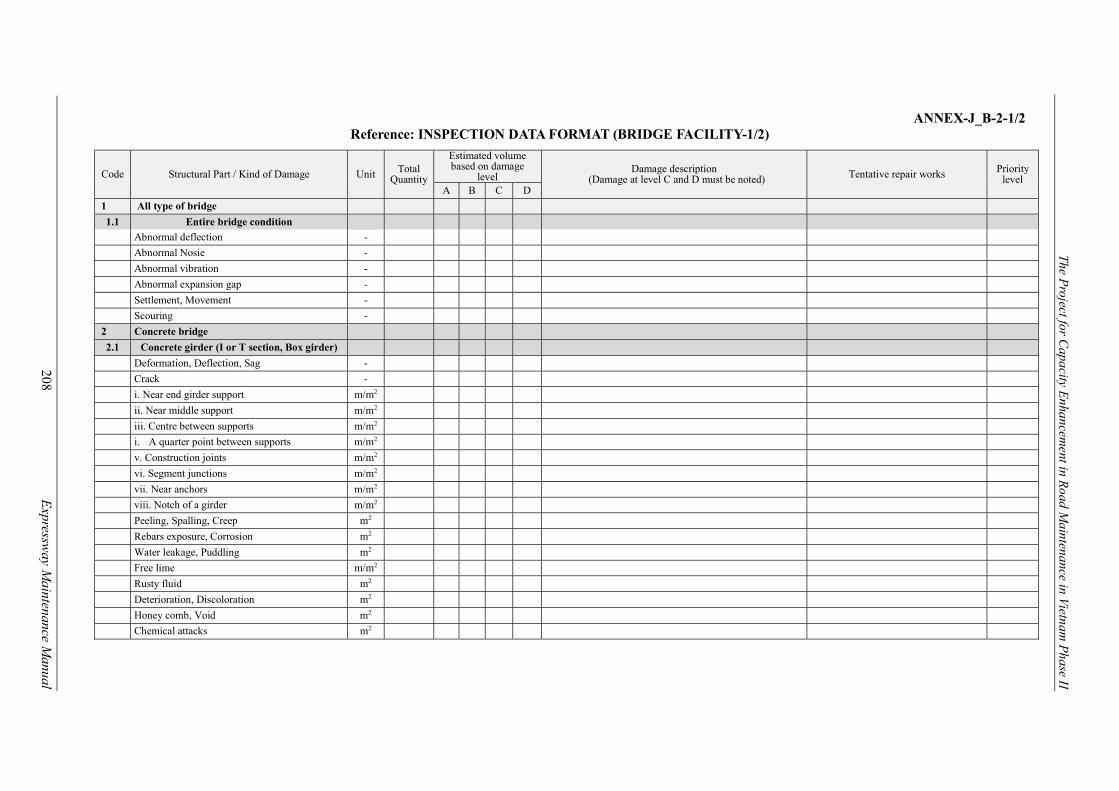
The Project for C
apacity Enhancem
ent in Road M
aintenance in Vietnam P
hase II
208
E
xpressway M
aintenance Manual
ANNEX-J_B-2-1/2
Reference: INSPECTION DATA FORMAT (BRIDGE FACILITY-1/2)
Code Structural Part / Kind of Damage Unit Total Quantity
Estimated volume based on damage
level Damage description
(Damage at level C and D must be noted) Tentative repair works Priority level
A B C D
1 All type of bridge
1.1 Entire bridge condition
Abnormal deflection -
Abnormal Nosie -
Abnormal vibration -
Abnormal expansion gap -
Settlement, Movement -
Scouring -
2 Concrete bridge
2.1 Concrete girder (I or T section, Box girder)
Deformation, Deflection, Sag -
Crack -
i. Near end girder support m/m2
ii. Near middle support m/m2
iii. Centre between supports m/m2
i. A quarter point between supports m/m2
v. Construction joints m/m2
vi. Segment junctions m/m2
vii. Near anchors m/m2
viii. Notch of a girder m/m2
Peeling, Spalling, Creep m2
Rebars exposure, Corrosion m2
Water leakage, Puddling m2
Free lime m/m2
Rusty fluid m2
Deterioration, Discoloration m2
Honey comb, Void m2
Chemical attacks m2
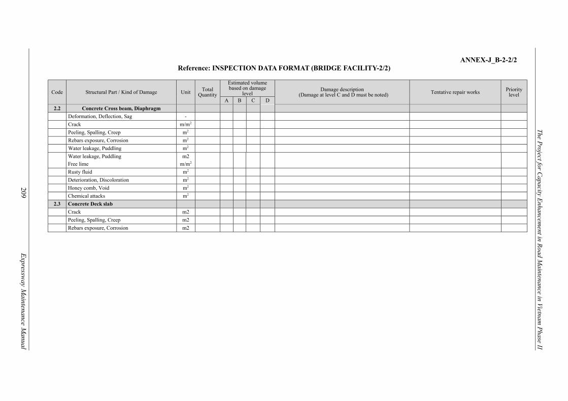
The Project for C
apacity Enhancem
ent in Road M
aintenance in Vietnam P
hase II
209
E
xpressway M
aintenance Manual
ANNEX-J_B-2-2/2
Reference: INSPECTION DATA FORMAT (BRIDGE FACILITY-2/2)
Code Structural Part / Kind of Damage Unit Total Quantity
Estimated volume based on damage
level Damage description
(Damage at level C and D must be noted) Tentative repair works Priority level
A B C D
2.2 Concrete Cross beam, Diaphragm
Deformation, Deflection, Sag -
Crack m/m2
Peeling, Spalling, Creep m2
Rebars exposure, Corrosion m2
Water leakage, Puddling m2
Water leakage, Puddling m2
Free lime m/m2
Rusty fluid m2
Deterioration, Discoloration m2
Honey comb, Void m2
Chemical attacks m2
2.3 Concrete Deck slab
Crack m2
Peeling, Spalling, Creep m2
Rebars exposure, Corrosion m2
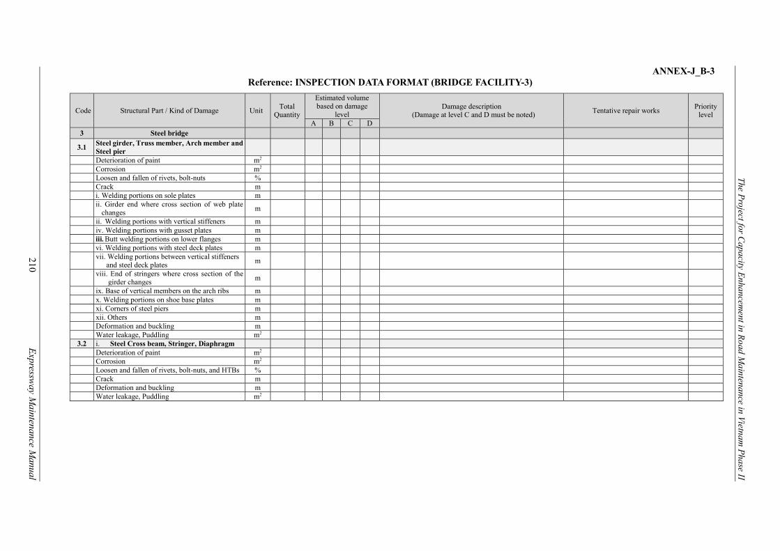
The Project for C
apacity Enhancem
ent in Road M
aintenance in Vietnam P
hase II
210
E
xpressway M
aintenance Manual
ANNEX-J_B-3 Reference: INSPECTION DATA FORMAT (BRIDGE FACILITY-3)
Code Structural Part / Kind of Damage Unit Total
Quantity
Estimated volume based on damage
level Damage description
(Damage at level C and D must be noted) Tentative repair works Priority
level A B C D
3 Steel bridge
3.1 Steel girder, Truss member, Arch member and Steel pier
Deterioration of paint m2 Corrosion m2 Loosen and fallen of rivets, bolt-nuts % Crack m i. Welding portions on sole plates m
ii. Girder end where cross section of web plate
changes m
ii. Welding portions with vertical stiffeners m iv. Welding portions with gusset plates m
iii. Butt welding portions on lower flanges m vi. Welding portions with steel deck plates m
vii. Welding portions between vertical stiffeners
and steel deck plates m
viii. End of stringers where cross section of the
girder changes m
ix. Base of vertical members on the arch ribs m x. Welding portions on shoe base plates m xi. Corners of steel piers m xii. Others m Deformation and buckling m Water leakage, Puddling m2
3.2 i. Steel Cross beam, Stringer, Diaphragm Deterioration of paint m2 Corrosion m2 Loosen and fallen of rivets, bolt-nuts, and HTBs % Crack m Deformation and buckling m Water leakage, Puddling m2
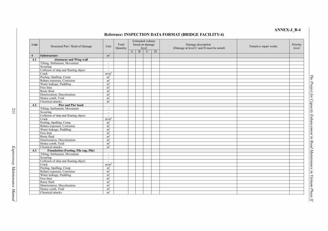
The Project for C
apacity Enhancem
ent in Road M
aintenance in Vietnam P
hase II
211
E
xpressway M
aintenance Manual
ANNEX-J_B-4 Reference: INSPECTION DATA FORMAT (BRIDGE FACILITY-4)
Code
Structural Part / Kind of Damage Unit Total
Quantity
Estimated volume based on damage
level Damage description
(Damage at level C and D must be noted) Tentative repair works Priority
level A B C D
4 Substructure m2 4.1 Abutment and Wing wall
Tilting, Settlement, Movement - Scouring - Collision of ship and floating object - Crack m/m2 Peeling, Spalling, Creep m2 Rebars exposure, Corrosion m2 Water leakage, Puddling m2 Free lime m2 Rusty fluid m2 Deterioration, Discoloration m2 Honey comb, Void m2 Chemical attacks m2
4.2 Pier and Pier head Tilting, Settlement, Movement - Scouring - Collision of ship and floating object - Crack m/m2 Peeling, Spalling, Creep m2 Rebars exposure, Corrosion m2 Water leakage, Puddling m2 Free lime m2 Rusty fluid m2 Deterioration, Discoloration m2 Honey comb, Void m2 Chemical attacks m2
4.3 Foundation (Footing, Pile cap, Pile) Tilting, Settlement, Movement - Scouring - Collision of ship and floating object - Crack m/m2 Peeling, Spalling, Creep m2 Rebars exposure, Corrosion m2 Water leakage, Puddling m2 Free lime m2 Rusty fluid m2 Deterioration, Discoloration m2 Honey comb, Void m2 Chemical attacks m2
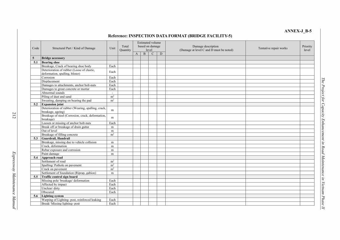
The Project for C
apacity Enhancem
ent in Road M
aintenance in Vietnam P
hase II
212
E
xpressway M
aintenance Manual
ANNEX-J_B-5 Reference: INSPECTION DATA FORMAT (BRIDGE FACILITY-5)
Code Structural Part / Kind of Damage Unit Total
Quantity
Estimated volume based on damage
level Damage description
(Damage at level C and D must be noted) Tentative repair works Priority
level A B C D
5 Bridge accessory 5.1 Bearing shoe
Breakage, Crack of bearing shoe body Each
Deterioration of rubber (Loose of elastic, deformation, spalling, blister)
Each
Corrosion Each Displacement Each Damages to attachments, anchor bolt-nuts Each Damages to grout concrete or mortar Each Abnormal sounds - Piling of dust and sand m2 Sweating, damping on bearing the pad m2
5.2 Expansion joint
Deterioration of rubber (Wearing, spalling, crack, breakage, ageing) m
Breakage of steel (Corrosion, crack, deformation, breakage) m
Loosen or missing of anchor bolt-nuts Each Break off or breakage of drain gutter m Out of level m Breakage of filling concrete m2
5.3 Guardrail, Handrail Breakage, missing due to vehicle collision m Crack, deformation m Rebar exposure and corrosion m Paint damage m
5.4 Approach road Settlement of road m2 Spalling/ Pothole on pavement m2 Crack on pavement m2 Settlement of foundation (Riprap, gabion) m
5.5 Traffic control sign board Missing pole/ breakage/ deformation Each Affected by impact Each Unclear/ dirty Each Obscured Each
5.6 Lighting system Warping of Lighting- post, reinforced leaking Each Break/ Missing lighting- post Each

The Project for C
apacity Enhancem
ent in Road M
aintenance in Vietnam P
hase II
213
E
xpressway M
aintenance Manual
ANNEX-J_T-1
INSPECTION DATA FORMAT (TUNNEL FACILITY)
(*1): Refer to the relevant articles in the Inspection Guideline.
Inspection Facility (*1) Damage Type (*1)
Concrete liningTunnel portalInner decoration boardTunnel drainage system
Serious damages- Cracks- Water leakage- Joints- ScouringDamages on drain system
Length(m)
width(cm)
Diameter(cm)
Depth(cm)
PieceVisual
observationLocationMemo
Photo withGPS Camera A, B, C, D, E M / M 2 / M 3 / Piece
NH00100 NORTHERN AREA RMB 1 RRMC236 1 0 NATIONAL HIGHWAY 1 3 0 3 120 D AC 2015 9 Tunnel lining Water leakage 0.2 NH00100-4 D -----Joint repair /Drainpipe installation
0.2 m ----- Sample Data
NH00100 NORTHERN AREA RMB 1 RRMC236 1 0 NATIONAL HIGHWAY 1 5 0 5 25 U AC 2015 9 Tunnel portal Cracks 10 NH00100-8 D Yes Crack seal 10 Sample data
ID Route NameBranch
NumberGeographical Area Jurisdiction
MaintenanceCompany
RouteNumber
NoteFrom
(km,m)To
(km,m)Date
(yyyy/mm)
Loocation Information
Surface
Type
DetailedInspection
SelectedRepair Work
Repair Work Volume MonitoringDamageRating
Damage Scale
Pavement Facility damage ConditionsKirometer Post
U/D

The Project for C
apacity Enhancem
ent in Road M
aintenance in Vietnam P
hase II
214
E
xpressway M
aintenance Manual
ANNEX-J_C-1
INSPECTION DATA FORMAT (CULVERT FACILITY)
Inspection Facility (*1) Damage Type (*1)
Reinforced concrete box-culvertReinforced concrete pipeculvertsCorrugated metal culvert
Serious damages- Cracks- Water leakage- Joints- ScouringDamages on drain system
Length(m)
width(cm)
Diameter(cm)
Depth(cm)
PieceVisual
observationLocationM emo
Photo withGPS Camera A, B, C, D, E M / M 2 / M 3 / Piece
NH00100 NORTHERN AREA RMB 1 RRMC236 1 0 NATIONAL HIGHWAY 1 3 0 3 120 D 2015 9Reinforced concrete
box- culvertJoint 5 NH00100-3 D -----
Joint repair /Drainpipe installation
0.2 m ----- Sample Data
NH00100 NORTHERN AREA RMB 1 RRMC236 1 0 NATIONAL HIGHWAY 1 5 0 5 25 U 2015 9 Tunnel portal Cracks 10 NH00100-4 D Yes Crack seal 10 Sample data
ID Route NameBranch
NumberGeographical Area Jurisdiction
MaintenanceCompany
RouteNumber
NoteFrom
(km,m)To
(km,m)Date
(yyyy/mm)
Loocation Information
DetailedInspection
SelectedRepair Work
Repair Work Volume MonitoringDamageRating
Kirometer Post
U/D
Pavement Facility damage Conditions
Damage Scale

The Project for C
apacity Enhancem
ent in Road M
aintenance in Vietnam P
hase II
215
E
xpressway M
aintenance Manual
ANNEX-J_TS-1
INSPECTION DATA FORMAT (TRAFFIC SAFETY FACILITY)
(*1): Refer to the relevant articles in the Inspection Guideline.
Inspection Facility (*1) Damage Type (*1)
GuardrailGuard CableConcrete Wall-typeGuard
Main member damageAccessary damageCorrosionFoundation damage
Length(m)
width(cm)
Diameter(cm)
Depth(cm)
PieceVisual
observationLocationM emo
Photo withGPS Camera A, B, C, D, E M / M 2 / M 3 / Piece
NH00100 NORTHERN AREA RMB 1 RRMC236 1 0 NATIONAL HIGHWAY 1 3 180 D 2015 9 Guard Rail Deformation 2 By accident NH00100-3 D ----- Replacement 2 ----- Sample Data
15 250 --- ---Concrete Wall-type
GuardCracks 1
Seriouscracks
NH00100-4 D ----- Replacement 1 ----- Sample data
ID Route NameBranch
NumberGeographical Area Jurisdiction
MaintenanceCompany
RouteNumber
NoteFrom
(km,m)To
(km,m)Date
(yyyy/mm)
Loocation Information
DetailedInspection
SelectedRepair Work
Repair Work Volume MonitoringDamageRating
Pavement Facility damage Conditions
Damage Scale
Kirometer Post
U/D

The Project for C
apacity Enhancem
ent in Road M
aintenance in Vietnam P
hase II
216
E
xpressway M
aintenance Manual
ANNEX-J_TM-1 INSPECTION DATA FORMAT (TRAFFIC MANAGEMENT FACILITY)
Inspection Facility (*1) Damage Type (*1)
Traffic signs Main member damageAccessary damageCorrosionFoundation damage
Length(m)
width(cm)
Diameter(cm)
Depth(cm)
PieceVisual
observationLocationM emo
Photo withGPS Camera A, B, C, D, E M / M 2 / M 3 / Piece
NH00100 NORTHERN AREA RMB 1 RRMC236 1 0 NATIONAL HIGHWAY 1 3 180 D 2015 9 Traffic s igns Deformation 1 By accident NH00100-3 D ----- Replacement 1 ----- Sample Data
ID Route NameBranch
NumberGeographical Area Jurisdiction
MaintenanceCompany
RouteNumber
NoteFrom
(km,m)To
(km,m)Date
(yyyy/mm)
Loocation Information
DetailedInspection
SelectedRepair Work
Repair Work Volume MonitoringDamageRating
Pavement Facility damage Conditions
Damage Scale
Kirometer Post
U/D

The Project for Capacity Enhancement in Road Maintenance in Vietnam Phase II
217 Expressway Maintenance Manual
ANNEX-K
PICTURE RECORDS
PHOTO NUMBER: PHOTO NUMBER:
ROAD ID ROAD ID
STATION POST STATION POST
PHOTO NUMBER: PHOTO NUMBER:
ROAD ID ROAD ID
STATION POST STATION POST
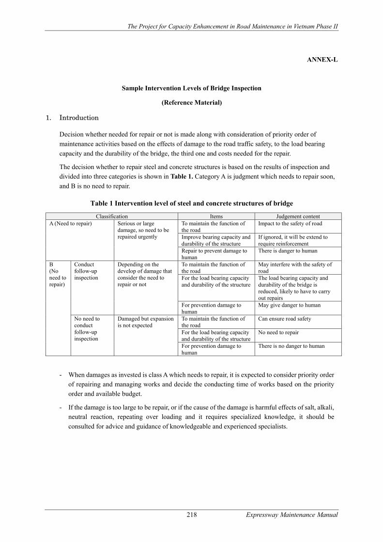
The Project for Capacity Enhancement in Road Maintenance in Vietnam Phase II
218 Expressway Maintenance Manual
ANNEX-L
Sample Intervention Levels of Bridge Inspection
(Reference Material)
1. Introduction
Decision whether needed for repair or not is made along with consideration of priority order of
maintenance activities based on the effects of damage to the road traffic safety, to the load bearing
capacity and the durability of the bridge, the third one and costs needed for the repair.
The decision whether to repair steel and concrete structures is based on the results of inspection and
divided into three categories is shown in Table 1. Category A is judgment which needs to repair soon,
and B is no need to repair.
Table 1 Intervention level of steel and concrete structures of bridge
Classification Items Judgement content A (Need to repair) Serious or large
damage, so need to be repaired urgently
To maintain the function of the road
Impact to the safety of road
Improve bearing capacity and durability of the structure
If ignored, it will be extend to require reinforcement
Repair to prevent damage to human
There is danger to human
B (No need to repair)
Conduct follow-up inspection
Depending on the develop of damage that consider the need to repair or not
To maintain the function of the road
May interfere with the safety of road
For the load bearing capacity and durability of the structure
The load bearing capacity and durability of the bridge is reduced, likely to have to carry out repairs
For prevention damage to human
May give danger to human
No need to conduct follow-up inspection
Damaged but expansion is not expected
To maintain the function of the road
Can ensure road safety
For the load bearing capacity and durability of the structure
No need to repair
For prevention damage to human
There is no danger to human
- When damages as invested is class A which needs to repair, it is expected to consider priority order
of repairing and managing works and decide the conducting time of works based on the priority
order and available budget.
- If the damage is too large to be repair, or if the cause of the damage is harmful effects of salt, alkali,
neutral reaction, repeating over loading and it requires specialized knowledge, it should be
consulted for advice and guidance of knowledgeable and experienced specialists.
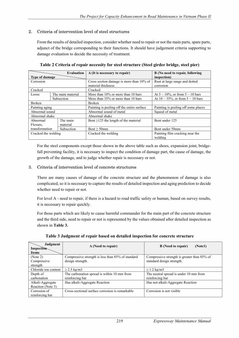
The Project for Capacity Enhancement in Road Maintenance in Vietnam Phase II
219 Expressway Maintenance Manual
2. Criteria of intervention level of steel structures
From the results of detailed inspection, consider whether need to repair or not the main parts, spare parts,
adjunct of the bridge corresponding to their functions. It should have judgement criteria supporting to
damage evaluation to decide the necessity of treatment.
Table 2 Criteria of repair necessity for steel structure (Steel girder bridge, steel pier)
Evaluation Type of damage
A (It is necessary to repair) B (No need to repair, following inspection)
Corrosion Cross section damage is more than 10% of material thickness
Rust at large range and dotted corrosion
Cracked Cracked Loose The main material More than 10% or more than 10 bars At 5 ~ 10%, or from 5 ~ 10 bars
Subsection More than 35% or more than 10 bars At 10 ~ 35%, or from 5 ~ 10 bars Broken Broken Painting aging Painting is peeling off the entire surface Painting is peeling off some places Abnormal sound Abnormal sound of metal Squeal of metal Abnormal shake Abnormal shake Abnormal Flexure, transformation
The main material
Bent ≥125 the length of the material Bent under 125
Subsection Bent ≥ 50mm Bent under 50mm Cracked the welding Cracked the welding Painting film cracking near the
welding
For the steel components except those shown in the above table such as shoes, expansion joint, bridge-
fall preventing facility, it is necessary to inspect the condition of damage part, the cause of damage, the
growth of the damage, and to judge whether repair is necessary or not.
3. Criteria of intervention level of concrete structures
There are many causes of damage of the concrete structure and the phenomenon of damage is also
complicated, so it is necessary to capture the results of detailed inspection and aging prediction to decide
whether need to repair or not.
For level A - need to repair, if there is a hazard to road traffic safety or human, based on survey results,
it is necessary to repair quickly.
For those parts which are likely to cause harmful commander for the main part of the concrete structure
and the third side, need to repair or not is represented by the values obtained after detailed inspection as
shown in Table 3.
Table 3 Judgment of repair based on detailed inspection for concrete structure
Judgment Inspection Items
A (Need to repair) B (Need to repair) (Note1)
(Note 2) Compressive strength
Compressive strength is less than 85% of standard design strength.
Compressive strength is greater than 85% of standard design strength.
Chloride ion content ≥ 2.5 kg/m3 ≤ 1.2 kg/m3 Depth of carbonation
The carbonation spread is within 10 mm from reinforcing bar
The neutral spread is under 10 mm from reinforcing bar
Alkali-Aggregate Reaction (Note 3)
Has alkali-Aggregate Reaction Has not alkali-Aggregate Reaction
Corrosion of reinforcing bar
Cross-sectional surface corrosion is remarkable Corrosion is not visible
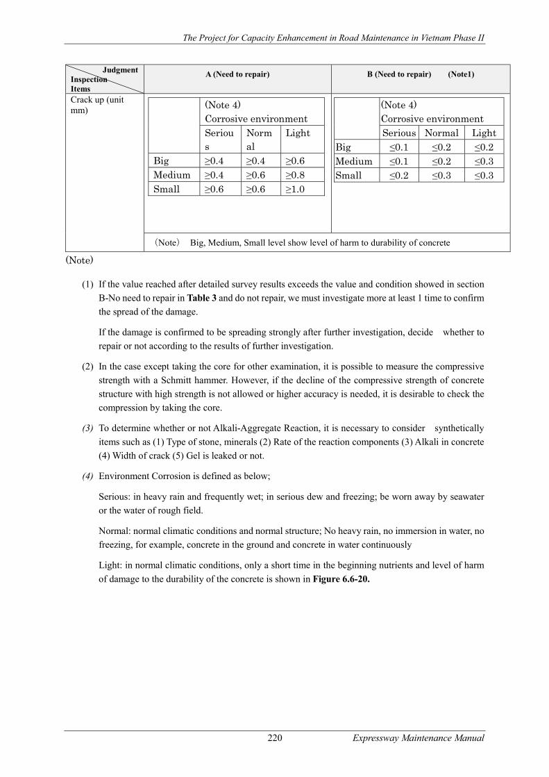
The Project for Capacity Enhancement in Road Maintenance in Vietnam Phase II
220 Expressway Maintenance Manual
Judgment Inspection Items
A (Need to repair) B (Need to repair) (Note1)
Crack up (unit mm)
(Note) Big, Medium, Small level show level of harm to durability of concrete
(Note)
(1) If the value reached after detailed survey results exceeds the value and condition showed in section
B-No need to repair in Table 3 and do not repair, we must investigate more at least 1 time to confirm
the spread of the damage.
If the damage is confirmed to be spreading strongly after further investigation, decide whether to
repair or not according to the results of further investigation.
(2) In the case except taking the core for other examination, it is possible to measure the compressive
strength with a Schmitt hammer. However, if the decline of the compressive strength of concrete
structure with high strength is not allowed or higher accuracy is needed, it is desirable to check the
compression by taking the core.
(3) To determine whether or not Alkali-Aggregate Reaction, it is necessary to consider synthetically
items such as (1) Type of stone, minerals (2) Rate of the reaction components (3) Alkali in concrete
(4) Width of crack (5) Gel is leaked or not.
(4) Environment Corrosion is defined as below;
Serious: in heavy rain and frequently wet; in serious dew and freezing; be worn away by seawater
or the water of rough field.
Normal: normal climatic conditions and normal structure; No heavy rain, no immersion in water, no
freezing, for example, concrete in the ground and concrete in water continuously
Light: in normal climatic conditions, only a short time in the beginning nutrients and level of harm
of damage to the durability of the concrete is shown in Figure 6.6-20.
(Note 4) Corrosive environment Serious
Normal
Light
Big ≥0.4 ≥0.4 ≥0.6 Medium ≥0.4 ≥0.6 ≥0.8 Small ≥0.6 ≥0.6 ≥1.0
(Note 4) Corrosive environment Serious Normal Light
Big ≤0.1 ≤0.2 ≤0.2 Medium ≤0.1 ≤0.2 ≤0.3 Small ≤0.2 ≤0.3 ≤0.3
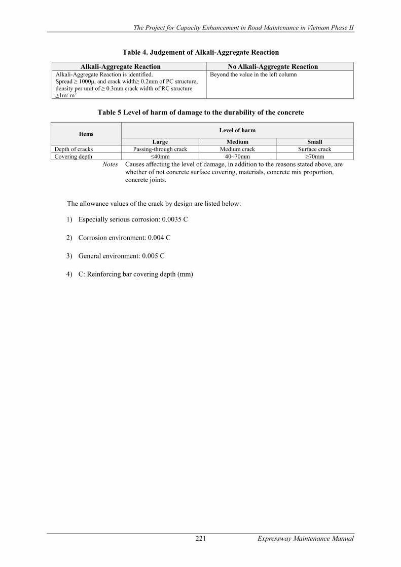
The Project for Capacity Enhancement in Road Maintenance in Vietnam Phase II
221 Expressway Maintenance Manual
Table 4. Judgement of Alkali-Aggregate Reaction
Alkali-Aggregate Reaction No Alkali-Aggregate Reaction Alkali-Aggregate Reaction is identified. Spread ≥ 1000μ, and crack width≥ 0.2mm of PC structure, density per unit of ≥ 0.3mm crack width of RC structure ≥1m/ m2
Beyond the value in the left column
Table 5 Level of harm of damage to the durability of the concrete
Items Level of harm
Large Medium Small Depth of cracks Passing-through crack Medium crack Surface crack Covering depth ≤40mm 40~70mm ≥70mm
Notes Causes affecting the level of damage, in addition to the reasons stated above, are whether of not concrete surface covering, materials, concrete mix proportion, concrete joints.
The allowance values of the crack by design are listed below:
1) Especially serious corrosion: 0.0035 C
2) Corrosion environment: 0.004 C
3) General environment: 0.005 C
4) C: Reinforcing bar covering depth (mm)