6T40-6T45 Updates and Product Concerns - Microsoft...Control Solenoid (w/Body & TCM) Valve Assembly...
40
6T40-6T45 Updates and Product Concerns Presented by: Steve Garrett ATRA
Transcript of 6T40-6T45 Updates and Product Concerns - Microsoft...Control Solenoid (w/Body & TCM) Valve Assembly...

6T40-6T45 Updates and Product Concerns
Presented by: Steve Garrett
ATRA

Connections Questions Survey
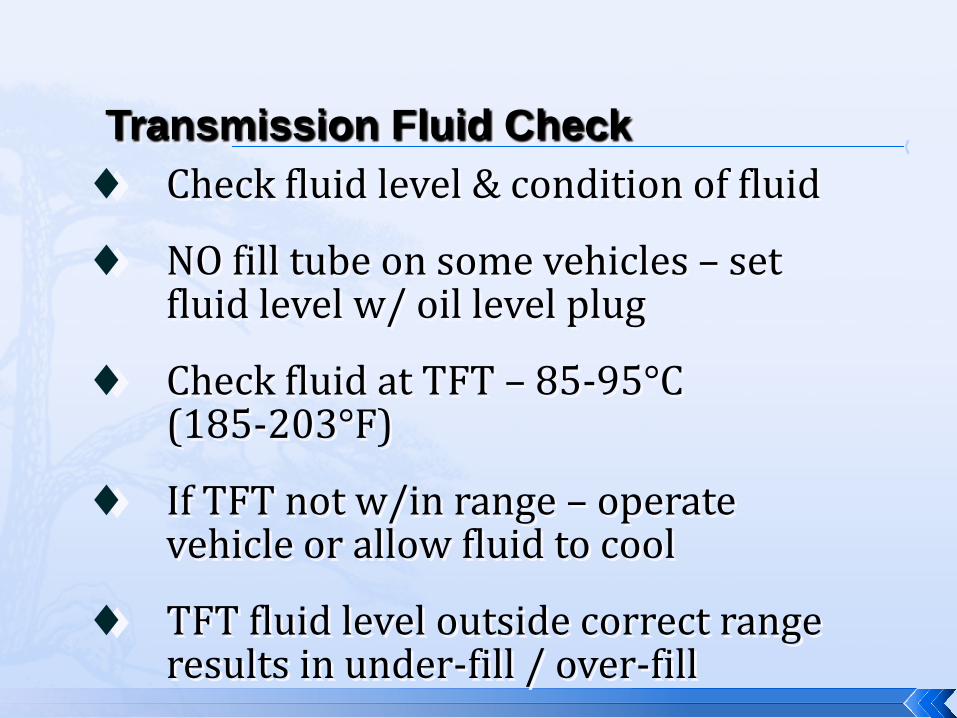
♦ Check fluid level & condition of fluid
♦ NO fill tube on some vehicles – set fluid level w/ oil level plug
♦ Check fluid at TFT – 85-95°C (185-203°F)
♦ If TFT not w/in range – operate vehicle or allow fluid to cool
♦ TFT fluid level outside correct range results in under-fill / over-fill
Transmission Fluid Check

♦ Connect scan tool / monitor TFT
♦ Start / idle engine
♦ Depress brake / shift gears 3 times
♦ Shift to PARK / ensure 500-800 RPM
♦ Idle 3 minutes for fluid to stabilize
Transmission Fluid Check
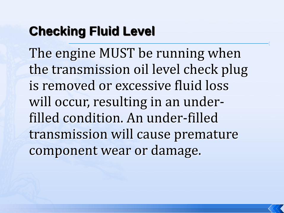
The engine MUST be running when the transmission oil level check plug is removed or excessive fluid loss will occur, resulting in an under-filled condition. An under-filled transmission will cause premature component wear or damage.
Checking Fluid Level
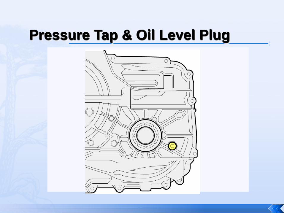
Pressure Tap & Oil Level Plug
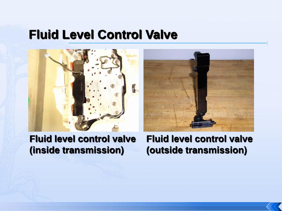
Fluid Level Control Valve
Fluid level control valve (inside transmission)
Fluid level control valve (outside transmission)

Control Solenoid Valve & TCM Solenoid Performance Test
DT-48616 DT-48616 Torque Sequence
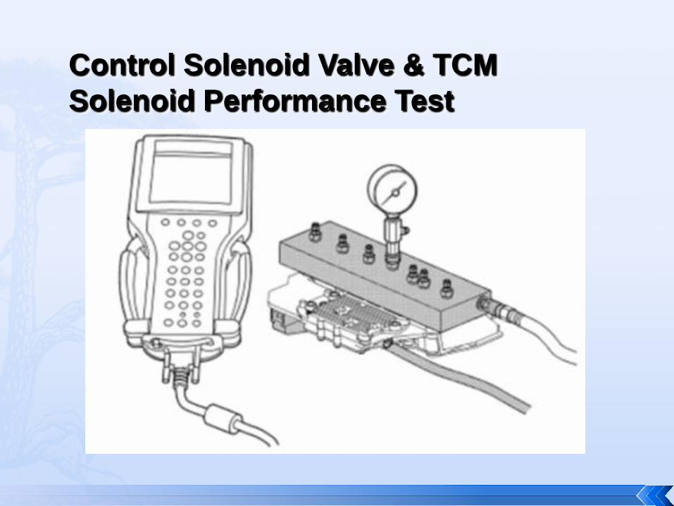
Control Solenoid Valve & TCM Solenoid Performance Test
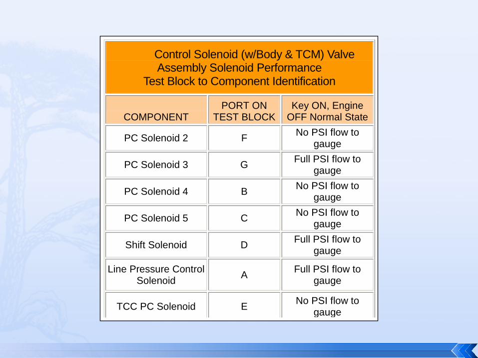
Control Solenoid (w/Body & TCM) Valve
Assembly Solenoid Performance Test Block to Component Identification
COMPONENT PORT ON
TEST BLOCK Key ON, Engine
OFF Normal State
PC Solenoid 2 F No PSI flow to gauge
PC Solenoid 3 G Full PSI flow to gauge
PC Solenoid 4 B No PSI flow to gauge
PC Solenoid 5 C No PSI flow to gauge
Shift Solenoid D Full PSI flow to gauge
Line Pressure Control Solenoid A Full PSI flow to
gauge
TCC PC Solenoid E No PSI flow to gauge

♦ Transmission internal service/ overhaul
♦ Valve body repair or replacement
♦ Solenoid Assembly replacement
♦ TCM software/calibration update
♦ Service in response to shift quality concern
Service Fast Learn Adapts Procedure
♦ 0% throttle / No RPM control
♦ 70º–100ºC (158º–212ºF) TFT
♦ Gear selector cycled 3X from P to R
Service Fast Learn Adapts Procedure Conditions
♦ PARK
♦ DRIVE
♦ REVERSE
Service Fast Learn Adapts Steps

If at any time during the procedure, required conditions are not met, Service Fast Learn Adapts may abort and the process may need to be started again from the beginning.
If power is lost or if the scan tool is disconnected, the procedure must be started over.
Adapts
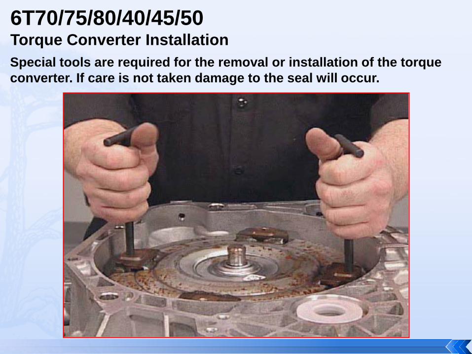
6T70/75/80/40/45/50 Torque Converter Installation Special tools are required for the removal or installation of the torque converter. If care is not taken damage to the seal will occur.

6T40 (RPO MH8) 6T40 BAS (RPO MHH) 6T45 (RPO MH7) 6T50 (RPO MHK) UPDATES FOR PRODUCT CONCERNS Beginning with the start of production (SOP) for the 2012 model year “MOST”
6T40/6T45/6T50 transaxles underwent massive changes that will have a “dramatic impact” on service of the units. The upgrades will be rolled out to future models during 2012/2014. The upgrades deal primarily with the control system (shift feel) but it does also apply to some other areas such as the clutches.
Models Effected for 2012 * Buick Lacrosse, Regal, Verano * Chevrolet Cruze 1.4L (RPO LUJ), Equinox, Malibu * GMC Terrain Models not effected for 2012 SOP, as they continue to use Gen 1 components * Chevrolet Cruze 1.8L (RPO LUW) * Chevrolet Sonic 1.8L (RPO LUW) * Chevrolet Captiva * Orlando Component interchange is now a major issue because the updated components for the
most part, CAN NOT be interchanged with the previously designed components. The system upgrades will be defined using the terms;
Gen 1-- 1st design- Previous design Gen 2 -- 2nd design- Updated design

6T40 TEHCM and Valve Body ID
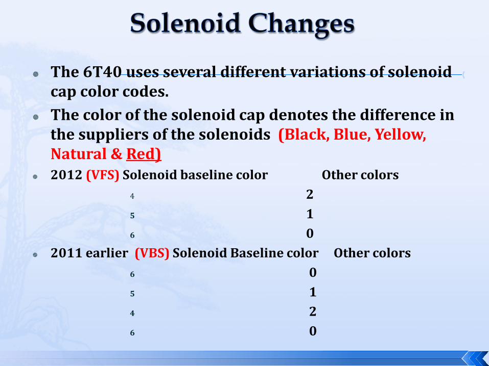
The 6T40 uses several different variations of solenoid cap color codes.
The color of the solenoid cap denotes the difference in the suppliers of the solenoids (Black, Blue, Yellow, Natural & Red)
2012 (VFS) Solenoid baseline color Other colors 4 2 5 1 6 0
2011 earlier (VBS) Solenoid Baseline color Other colors 6 0 5 1 4 2 6 0

The TEHCM used with the Gen II controls system does not use pressure switches. Instead the TEHCM (TCM) utilizes a new process known as “Clutch Pulse Learning”. “The TCM momentarily commands a clutch on at low pressure. The pressure pulse commands are increased until an interruption in transmission input speed is detected. The return spring force is the first characteristic to be learned. After the spring force is learned, the TCM uses different pulse commands to determine the volume of transmission fluid required to move the clutch piston to the point of clutch apply. The TCM calculates fill time based on the learned volume. The CP Learn is conducted during steady conditions in 3rd, 5th and 6th gear. The CP Learn for the 4-5-6 clutch is enabled in 3rd gear. CP Learn for the 1-2-3-4 clutch and 2–6 clutch is enabled in 5th gear. CP Learn for the 3-5-R clutch is enabled in 6th gear. A rough road condition could give a false reading for transmission input speed interruption. When rough road conditions are detected, CP Learn is aborted until road conditions improve.” “When a CP Learn is occurring, a slight bump or drag may be detected momentarily. The CP Learn will occur on the average vehicle every 1250 miles (2012 km). This is a normal condition and no repair attempts should be performed. The frequency of CP Learn is normally determined by the number of clutch apply cycles. The TCM will also initiate a CP Learn in advance of the clutch apply counter if shifts are detected which indicate an improper clutch fill time.”
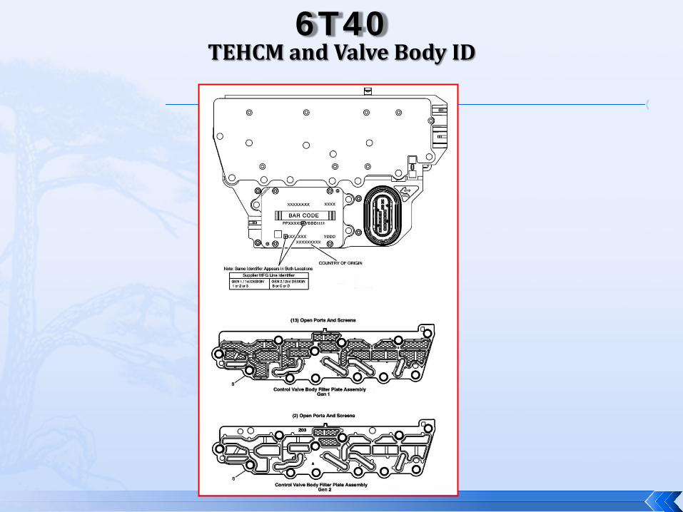
6T40 TEHCM and Valve Body ID

6T40/45/50 Updates
Gen1 = 1st design = previous design Gen 2 = 2nd design = updated design
A code with a 1, 2 or 3 in
the identifier is
a Generation 1, while a
code with a B, C or D in
the identifier is a
Generation 2.
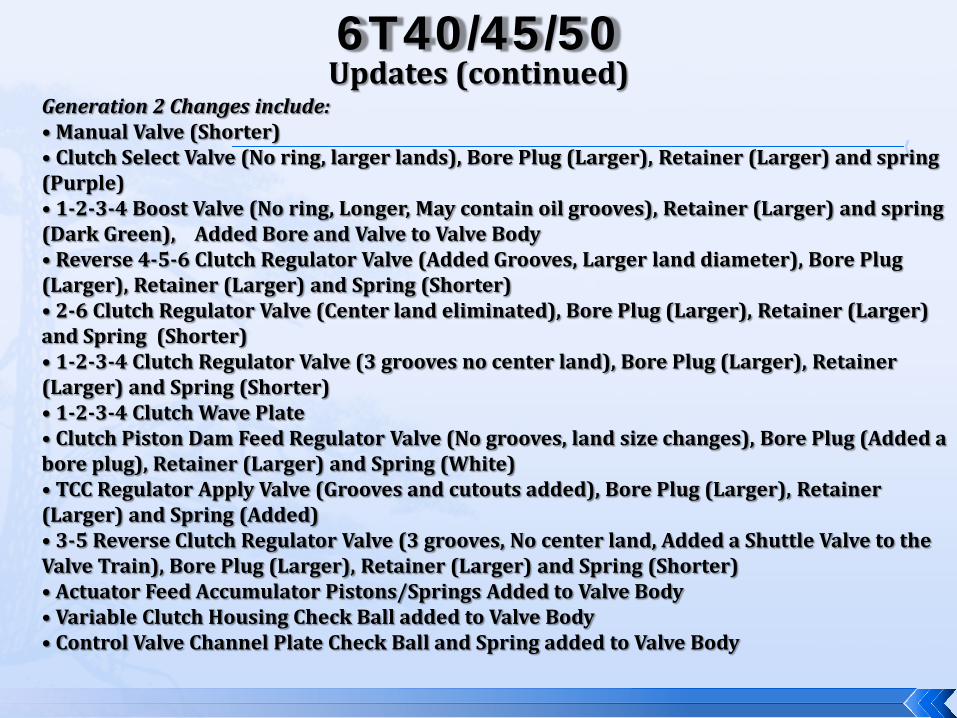
6T40/45/50 Updates (continued)
Generation 2 Changes include: • Manual Valve (Shorter) • Clutch Select Valve (No ring, larger lands), Bore Plug (Larger), Retainer (Larger) and spring (Purple) • 1-2-3-4 Boost Valve (No ring, Longer, May contain oil grooves), Retainer (Larger) and spring (Dark Green), Added Bore and Valve to Valve Body • Reverse 4-5-6 Clutch Regulator Valve (Added Grooves, Larger land diameter), Bore Plug (Larger), Retainer (Larger) and Spring (Shorter) • 2-6 Clutch Regulator Valve (Center land eliminated), Bore Plug (Larger), Retainer (Larger) and Spring (Shorter) • 1-2-3-4 Clutch Regulator Valve (3 grooves no center land), Bore Plug (Larger), Retainer (Larger) and Spring (Shorter) • 1-2-3-4 Clutch Wave Plate • Clutch Piston Dam Feed Regulator Valve (No grooves, land size changes), Bore Plug (Added a bore plug), Retainer (Larger) and Spring (White) • TCC Regulator Apply Valve (Grooves and cutouts added), Bore Plug (Larger), Retainer (Larger) and Spring (Added) • 3-5 Reverse Clutch Regulator Valve (3 grooves, No center land, Added a Shuttle Valve to the Valve Train), Bore Plug (Larger), Retainer (Larger) and Spring (Shorter) • Actuator Feed Accumulator Pistons/Springs Added to Valve Body • Variable Clutch Housing Check Ball added to Valve Body • Control Valve Channel Plate Check Ball and Spring added to Valve Body

6T40/45/50 • Updated Spacer Plate and Gaskets • 3-5 Reverse Clutch Friction material change • 3-5 Reverse Clutch Wave Plate • 3-5 Reverse Return Springs • 4-5-6 Clutch Piston (Pocket changes for new return spring design), Fluid Piston Dam, Return Springs, Snap Ring (Stepped) • 4-5-6 Piston Seal relocated in Housing • 1-2-3-4 Clutch Friction material (Internal teeth cutouts for ID of 2nd design) • 2-6 Clutch Friction material (Internal teeth cutouts for ID of 2nd design) • 2-6 Clutch Return Spring (Internal teeth cutouts for ID of 2nd design) • 2-6 Clutch Wave Plate • Pump, Bushing, Front Seal, Pressure Regulator Valve and Spring • Input Shaft Support and Support Seal Rings, for the 3-5-Reverse and 4-5-6 Clutches (Changed from 4 Seals on Support to 3 Seals, Support diameter is smaller) • TEHCM Solenoids changed from a VBS (Variable Bleed Solenoid) to a VFS (Variable Feed Solenoid) (Includes the need for a major TEHCM programming change)
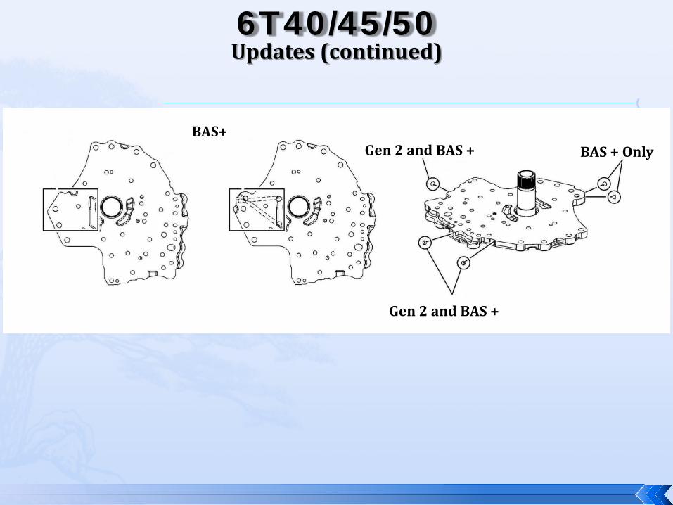
6T40/45/50 Updates (continued)
BAS+
Gen 2 and BAS +
Gen 2 and BAS + BAS + Only

Updates (continued) 6T40/45/50
Gen 2 BAS+ Gen 2
Rubber Exterior Steel Exterior
Pump Bushing Pump Bushing
Gen 2 BAS+
Gen 2
Pressure Regulator Valve
Gen 2 and BAS+
Ring Land Diameter
Gen 2 and BAS+
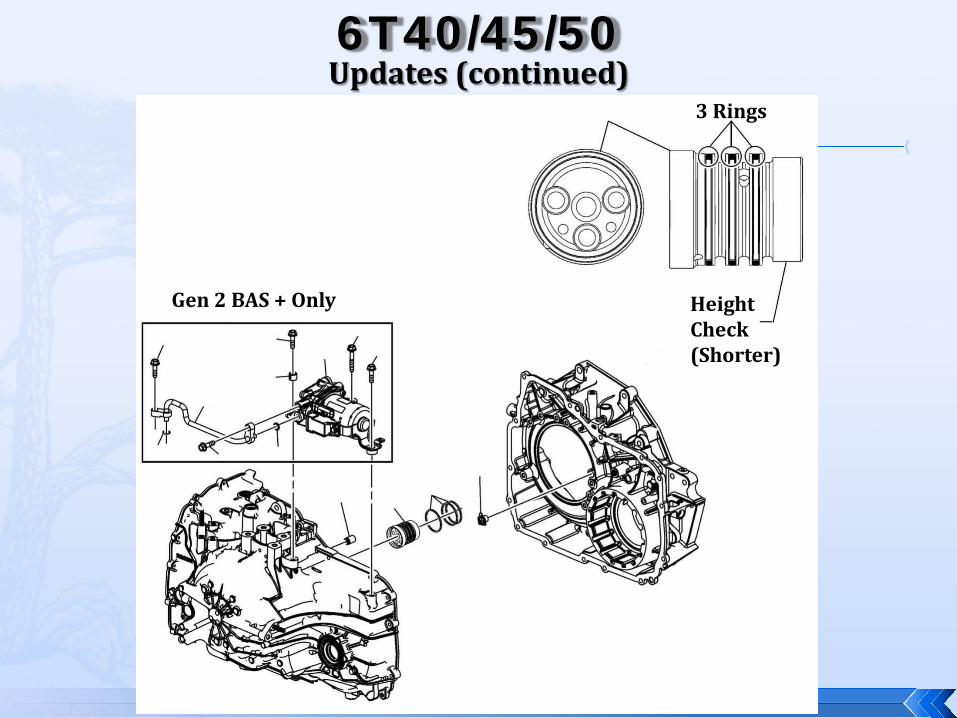
6T40/45/50 Updates (continued)
3 Rings
Height Check (Shorter)
Gen 2 BAS + Only
6T40/45/50 Updates (continued)
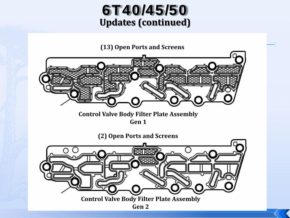
(13) Open Ports and Screens
(2) Open Ports and Screens
Control Valve Body Filter Plate Assembly Gen 1
Control Valve Body Filter Plate Assembly Gen 2
6T40/45/50 Updates (continued)
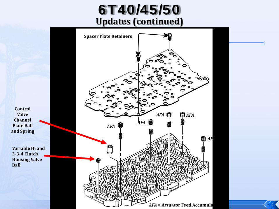
AFA
Spacer Plate Retainers
Control Valve
Channel Plate Ball
and Spring
Variable Hi and 2-3-4 Clutch Housing Valve Ball
AFA AFA
AFA AFA
AFA
AFA = Actuator Feed Accumulators

6T40/45/50 Updates (continued)

6T40/45/50 Updates (continued)
TCC Regulator Valve (No Center Land, (3) Grooves
2–6 Clutch Regulator Valve (No Center Land)
1-2-3-4 Clutch Regulator Valve (No Center Land (3) Grooves)
Low/Reverse & 4-5-6 Clutch Regulator Valve ((3) Grooves)
Default Override Valve
6T40/45/50 Updates (continued)
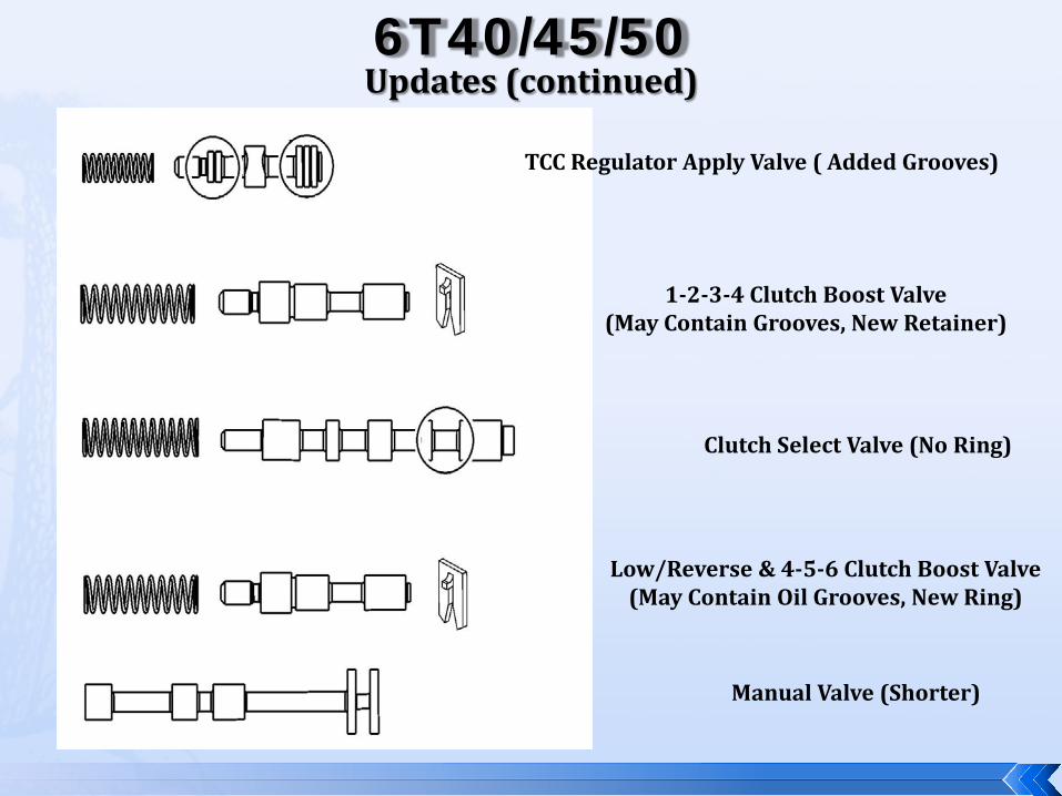
TCC Regulator Apply Valve ( Added Grooves)
1-2-3-4 Clutch Boost Valve (May Contain Grooves, New Retainer)
Clutch Select Valve (No Ring)
Low/Reverse & 4-5-6 Clutch Boost Valve (May Contain Oil Grooves, New Ring)
Manual Valve (Shorter)
6T40/45/50 Updates (continued)
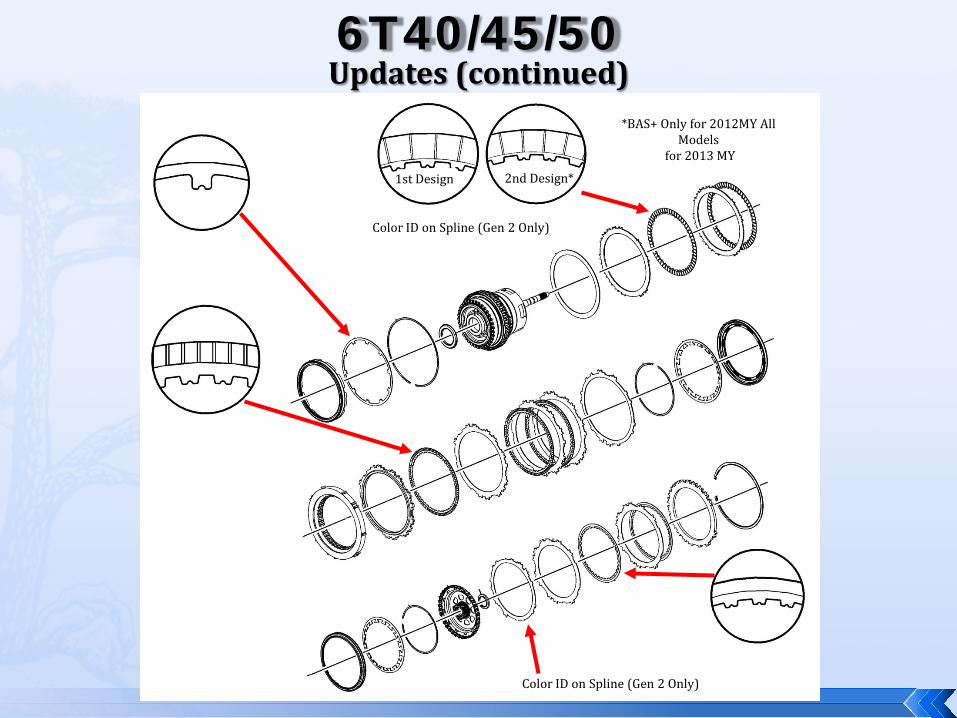
1st Design 2nd Design*
*BAS+ Only for 2012MY All Models
for 2013 MY
Color ID on Spline (Gen 2 Only)
Color ID on Spline (Gen 2 Only)
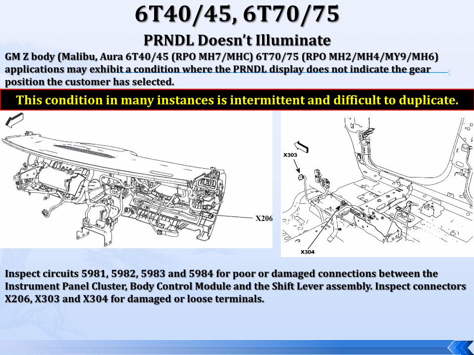
6T40/45, 6T70/75 PRNDL Doesn’t Illuminate
GM Z body (Malibu, Aura 6T40/45 (RPO MH7/MHC) 6T70/75 (RPO MH2/MH4/MY9/MH6) applications may exhibit a condition where the PRNDL display does not indicate the gear position the customer has selected.
Inspect circuits 5981, 5982, 5983 and 5984 for poor or damaged connections between the Instrument Panel Cluster, Body Control Module and the Shift Lever assembly. Inspect connectors X206, X303 and X304 for damaged or loose terminals.
This condition in many instances is intermittent and difficult to duplicate.
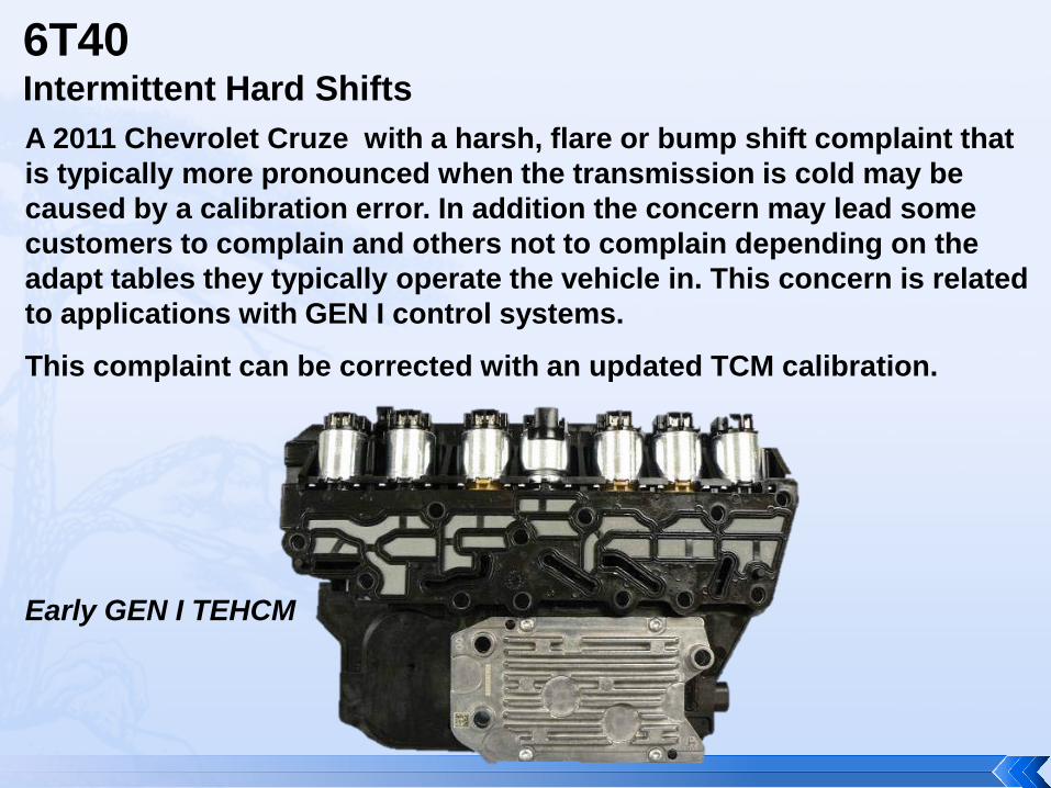
6T40 Intermittent Hard Shifts A 2011 Chevrolet Cruze with a harsh, flare or bump shift complaint that is typically more pronounced when the transmission is cold may be caused by a calibration error. In addition the concern may lead some customers to complain and others not to complain depending on the adapt tables they typically operate the vehicle in. This concern is related to applications with GEN I control systems.
This complaint can be corrected with an updated TCM calibration.
Early GEN I TEHCM

6T40 P0723 Sets A 2009 (Z BODY) Malibu, Aura, G6 with the 2.4L engine may set a Output Speed Sensor code P0723 caused by a calibration error. If there are no problems found with the output speed sensor. The TCM calculation strategy has been updated to correct this problem. Reflash the TCM with the new strategy.
Output Speed Sensor
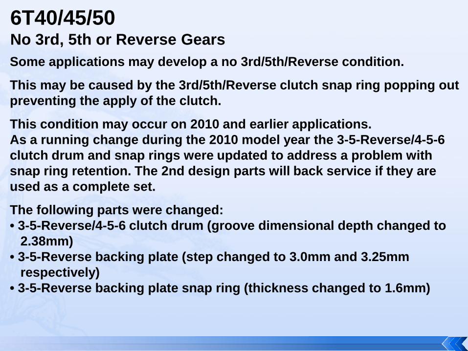
6T40/45/50 No 3rd, 5th or Reverse Gears Some applications may develop a no 3rd/5th/Reverse condition.
This may be caused by the 3rd/5th/Reverse clutch snap ring popping out preventing the apply of the clutch.
This condition may occur on 2010 and earlier applications. As a running change during the 2010 model year the 3-5-Reverse/4-5-6 clutch drum and snap rings were updated to address a problem with snap ring retention. The 2nd design parts will back service if they are used as a complete set.
The following parts were changed: • 3-5-Reverse/4-5-6 clutch drum (groove dimensional depth changed to 2.38mm) • 3-5-Reverse backing plate (step changed to 3.0mm and 3.25mm respectively) • 3-5-Reverse backing plate snap ring (thickness changed to 1.6mm)
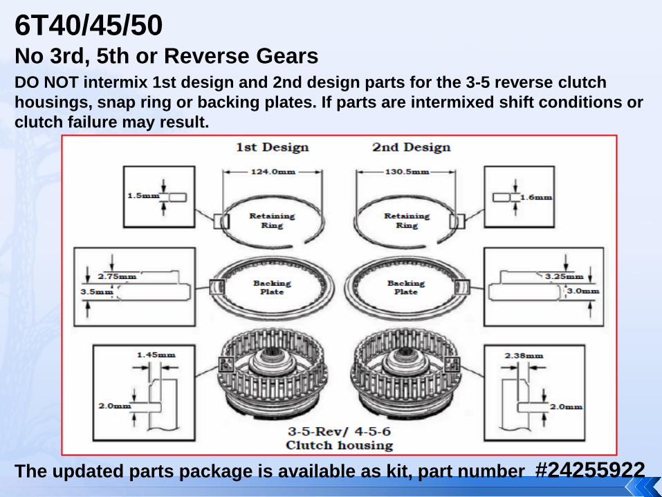
6T40/45/50 No 3rd, 5th or Reverse Gears DO NOT intermix 1st design and 2nd design parts for the 3-5 reverse clutch housings, snap ring or backing plates. If parts are intermixed shift conditions or clutch failure may result.
The updated parts package is available as kit, part number #24255922

6T40/45/50 Hard Shifts, Broken 3-5-Reverse Wave Plate, Possible DTC P0776 Set
2011 and earlier and some 2012/2013 6T40/45/50 applications with the generation 1 control system may exhibit a hard shift concern.
This may be caused by the 3-5-Reverse wave plate being broken. The wave plate may have broken due to the design of the 3-5-Reverse piston.
The previous piston design can lead to a fatigue failure of the wave plate. In addition the technician may find DTC P0776 set. The TCM detects an incorrect oncoming clutch gear ratio, or flare, when the 3-5-R clutch is commanded ON for 3 seconds and the transmission input shaft speed is 200 RPM or greater from the anticipated input shaft speed.
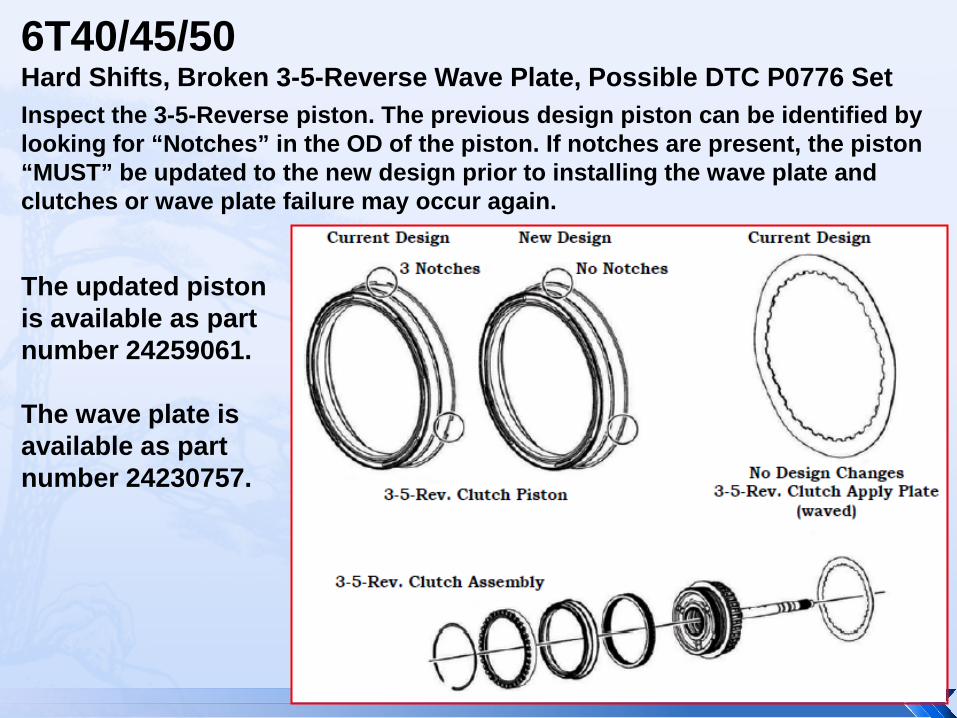
6T40/45/50 Hard Shifts, Broken 3-5-Reverse Wave Plate, Possible DTC P0776 Set Inspect the 3-5-Reverse piston. The previous design piston can be identified by looking for “Notches” in the OD of the piston. If notches are present, the piston “MUST” be updated to the new design prior to installing the wave plate and clutches or wave plate failure may occur again.
The updated piston is available as part number 24259061. The wave plate is available as part number 24230757.

Questions?


![INDEX [ ] · PDF fileGM Only Resistance Chart Cavities Component 1-2 Shift Solenoid (A) 2-3 Shift Solenoid (B) TCC/PWM Solenoid EPC Solenoid Input Speed Sensor Output Speed Sensor](https://static.fdocuments.us/doc/165x107/5ab082127f8b9a6b468b5a12/index-only-resistance-chart-cavities-component-1-2-shift-solenoid-a-2-3-shift.jpg)