6Steering System ENGLISH-G9180
47
Service Manual of RS8160 Road Roller 6 Steering System SERVICE MANUAL
-
Upload
george-jhonson -
Category
Documents
-
view
11 -
download
0
description
Steering System ENGLISH-G9180
Transcript of 6Steering System ENGLISH-G9180

Service Manual of RS8160 Road Roller
6 Steering System
SERVICE MANUAL


Service Manual for G9180 Grader
I
CONTENTS
6 Steering System ................................................................................................... 6-1
61 General ................................................................................................................. 6-1
611 Location of Steering System Components .................................................. 6-2
612 Steering System Principle Description ........................................................ 6-3
62 Description, Disassembly and Assembly of Main Components ......................... 6-6
621 Steering Pump .............................................................................................. 6-6
622 Priority Valve ............................................................................................ 6-11
623 Steering Gear ............................................................................................. 6-12
624 Steering Control Mechanism Assembly .................................................... 6-18
625 Front Axle .................................................................................................. 6-19
626 Steering Cylinder ....................................................................................... 6-38
63 Pressure Measurement of Steering Hydraulic System ...................................... 6-39
64 Deflation of Steering Hydraulic System ........................................................... 6-40
65 Diagnosis and Solutions for Common Faults of Steering System .................... 6-41


Service Manual for G9180 Grader
6-1
6 Steering System
61 General
G9180 grader is equipped with full hydraulic steering system. The system has the advantages of
compact structure, high sensitivity, good stability, flexible and easy operation, shock absorption and
free of extra lubricating device. Besides, manual steering is available when steering power source
(pressure oil) is cut off.
Fig. 6-1 Principle diagram of steering system
1 Steering cylinder 2 Steering gear 3 Priority valve 4 Steering pump
① Working hydraulic system ② Brake hydraulic system

Service Manual for G9180 Grader
6-2
611 Location of Steering System Components
Fig
. 6
-2 L
oca
tion o
f st
eeri
ng s
yst
em
1 S
teer
ing p
um
p
2 P
riori
ty v
alve
3 S
teer
ing g
ear
4 S
teer
ing c
yli
nder
5 P
ress
ure
mea
suri
ng p
ort

Service Manual for G9180 Grader
6-3
612 Steering System Principle Description
The principle of hydraulic steering system is illustrated in Fig. 6-1. Steering system and the left
multitandem valve share the same high-pressure gear pump, the pump absorbs oil from hydraulic
tank, pressure oil enters the priority valve through port P, then the oil flows into steering gear from
port CF of priority valve. When turning the steering wheel, steering gear will send pressure oil into
steering cylinder to carry out front-wheel steering.
When the steering gear is in neutral position
Steering gear
Priority valve
Oil tank
Steering
pump
Filter
Fig. 6-3 Oil line when steering gear is in neutral position
As shown in Fig. 6-3, if the engine flames out, the pump will stop supplying; the control spring of
priority valve will force the spool to move right to connect port CF. After the engine is started,
hydraulic oil in the tank flows into priority valve through steering pump, the priority valve will
allocate oil to steering gear through port CF. The pressure oil in CF port will also act on both ends of
the priority valve, and the oil in the left end will flow back to the radiator through the orifice in
steering gear and port LS, pressure loss will be formed in this case. Resultant force of the spring and
pressure oil in the left end is smaller than the force produced by the pressure oil in the right end, the
spool will move to left, opening degree of port EF will increase, while that of port CF will decrease,
at this point, oil flow in CF oil line is very small and most oil will be sent to working hydraulic

Service Manual for G9180 Grader
6-4
system. When working system is not working, the pressure oil will return to hydraulic oil tank
through neutral position of multitandem valve.
When steering
When relative angular displacement is produced between the valve spool and valve bush of steering
gear, the variable orifice in steering gear will communicate with metering motor, and the passage to
the radiator will closed in the meantime. This change will result in pressure rise of oil in left end of
priority valve, and force the spool to find a new equilibrium position. If increase the rotating speed of
steering wheel, in the moment of change, the value of flow in the steering gear is less than the product
of steering wheel rotating speed and steering gear displacement, and rotating speed of valve bush
driven by metering mechanism is lower than rotating speed of spool driven by steering wheel, so
angular displacement of spool to valve bush increases and opening degree of variable orifice
increases. At this point, larger flow is needed to produce the same differential pressure as the one
before the change between two ends of the variable orifice to force the priority valve spool to move
right. So CF port opening degree of priority valve increases with the increase the increase of steering
wheel rotating speed. Finally, the flow valve in the steering gear will equal to the product of steering
wheel rotating speed and steering gear displacement.
Steering gear
Priority valve
Filter
Oil tank
Steering pump
Figure 6-4 Oil line when steering

Service Manual for G9180 Grader
6-5
When steering load exceeds the rated value or the steering cylinder reaches its stroke end
When steering load exceeds the rated value or steering cylinder reaches its stroke end and if you
keep turning the steering wheel, the oil cannot flow in to the cylinder. At this point, loading pressure
skyrockets, while differential pressure between two ends of variable orifice reduces sharply. When
steering oil line pressure exceeds the setting valve of steering safety valve, this valve will open to
work. Pressure loss produced when pressure oil flows through variable orifice, and this differential
pressure pass to two ends of priority valve spool to force the spool to move left, which result in
decrease of CF port opening degree, and decrease of EF port opening degree, in this way, the
pressure of oil in steering line will reduce.
Steering when engine flames out
When engine is not working, the metering mechanism can work as an oil pump, it can supply
pressure oil to the steering cylinders. Under this circumstance, the oil in oil return chamber of
steering cylinder will return to upstream of the variable orifice through the check valve inside the
steering gear.
The grader adopts dynamic signal load sensing non-reactive steering gear. Features of the
steering system are:
1. Good compensation for steering load change.
2. The steering hydraulic system and working hydraulic system are designed without interference
to each other.
3. The main circuit always takes supplying pressure oil to steering system as first priority.
4. Only small flow goes through steering gear when steering wheel is in neutral position, which is
energy-saving. The main circuit always takes supplying pressure oil to steering system as first
priority, the steering operation is reliable.
5. Neutral position pressure characteristic is not subject to displacement, flow amplifying function
is available.
6. Compared static signal steering gear, starting performance in cold climates is improved, as well
as reliability and stability of the system.
Service Manual for G9180 Grader
6-6
62 Description, Disassembly and Assembly of Main Components
621 Steering Pump
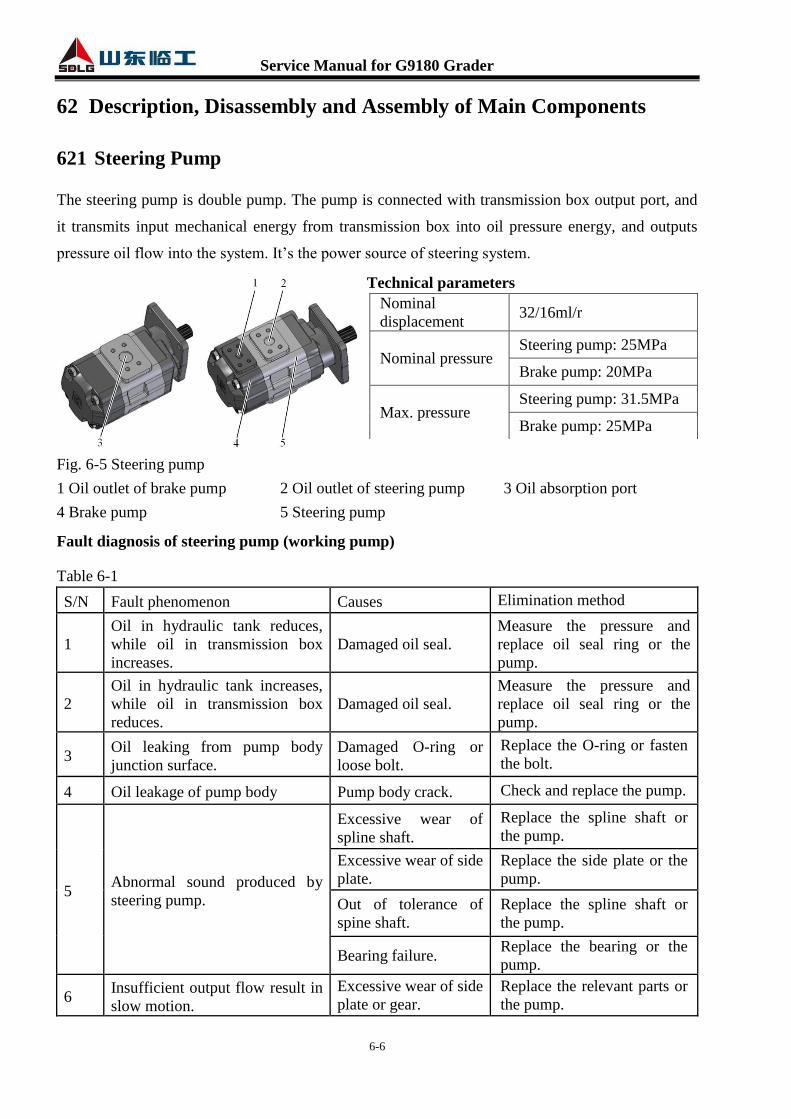
The steering pump is double pump. The pump is connected with transmission box output port, and
it transmits input mechanical energy from transmission box into oil pressure energy, and outputs
pressure oil flow into the system. It’s the power source of steering system.
Technical parameters
Fig. 6-5 Steering pump
1 Oil outlet of brake pump 2 Oil outlet of steering pump 3 Oil absorption port
4 Brake pump 5 Steering pump
Fault diagnosis of steering pump (working pump)
Table 6-1
S/N Fault phenomenon Causes Elimination method
1
Oil in hydraulic tank reduces,
while oil in transmission box
increases.
Damaged oil seal.
Measure the pressure and
replace oil seal ring or the
pump.
2
Oil in hydraulic tank increases,
while oil in transmission box
reduces.
Damaged oil seal.
Measure the pressure and
replace oil seal ring or the
pump.
3 Oil leaking from pump body
junction surface.
Damaged O-ring or
loose bolt.
Replace the O-ring or fasten
the bolt.
4 Oil leakage of pump body Pump body crack. Check and replace the pump.
5 Abnormal sound produced by
steering pump.
Excessive wear of
spline shaft.
Replace the spline shaft or
the pump.
Excessive wear of side
plate.
Replace the side plate or the
pump.
Out of tolerance of
spine shaft.
Replace the spline shaft or
the pump.
Bearing failure. Replace the bearing or the
pump.
6 Insufficient output flow result in
slow motion.
Excessive wear of side
plate or gear.
Replace the relevant parts or
the pump.
Nominal
displacement 32/16ml/r
Nominal pressure Steering pump: 25MPa
Brake pump: 20MPa
Max. pressure Steering pump: 31.5MPa
Brake pump: 25MPa

Service Manual for G9180 Grader
6-7
Disassembly of working pump
ATTENTION
1. Before disassembling the steering pump, please park the machine in maintenance position
properly. Refer to Page 10 in Safety & Environment.
2. When dismantling the hydraulic pipeline, do not screw off the nut connecting to the oil
port rashly. Loosen the nut gradually until the oil spills out so as to prevent the oil splash
due to incomplete pressure relief.
3. During dismantling the steering system, necessary protective measures should be taken
for each pipeline and oil port to prevent debris like dust from entering the steering
system.
4. During dismantling the steering system, please collect the remnant hydraulic oil with
appropriate vessel when disconnecting a pipe, and pour the collected oil into a dedicated
hydraulic oil recycling bin after the maintenance work.
5. When assembling, be sure to replace the seal with a new one, related standards of
tightening torque in this manual must be strictly followed.
1. Connect a hose to the oil drain valve on the
bottom of hydraulic tank, and put a clean
vessel under the other end of the hose. Open
the drain valve of the tank to drain the
hydraulic oil out. (Open the filling cap of the
tank to accelerate the draining speed)
ATTENTION
Cover up the discharged oil to avoid
contamination.
1 2
Fig. 6-6
1 Oil drain valve
2 Hose

Service Manual for G9180 Grader
6-8
2. Remove the fixing bolts of the cover plate,
take down the bolts and cover plate.
Cover plate
3. Remove the fixing bolts of steering pump oil
absorption steel pipe, take down the bolts and
fission flange, and then remove the steel pipe
and O-shape ring.
4. Disconnect the oil outlet rubber hose of
steering pump, and the oil outlet rubber hose
of brake pump.
1 2
Fig. 6-7
1 Cover plate 2 Cover plate
1
Fig. 6-8
1 Oil absorption steel pipe
1 2
Fig. 6-9
1 Oil outlet of steering pump
2 Oil outlet of brake pump

Service Manual for G9180 Grader
6-9
5. Remove the connecting bolts of steering pump
and transmission box, take down the bolts and
gaskets.
6. Hang the pump with lifting rope, and then use
a copper bar to knock it gently, take down the
pump and the sealing gasket.
Steering pump
7. Remove the fixing screws of the two straight
joints (on the two oil outlet ports), and then
take down the fission flanges and straight
joints.
Assembly of steering pump
1. Install the two straight joints to the two oil
outlet ports of the double pump with screws
and fission flange respectively.
2. Install the double pump to the transmission
box with M12×35 nuts, gaskets and sealing
gasket.
Steering pump
ATTENTION
Be sure to tighten the studs first.
3. Put an O-ring in the O-ring groove of each
straight joint. Connect the oil outlet rubber
hose of steering pump, and the oil outlet
rubber hose of brake pump to the
corresponding straight joint with four M10×30
and a fission flange respectively.
1
Fig. 6-10
1 Bolt
1
Fig. 6-11
1 Bolt
1 2
Fig. 6-12
1 Oil outlet of steering pump
2 Oil outlet of brake pump

Service Manual for G9180 Grader
6-10
4. Put O-ring in the O-ring groove of the pump
oil absorption steel pipe joint. Fix the pipe on
the oil absorption port with four M10×35 and a
fission flange.
5. Install the cover plate.
Cover plate
6. Fill hydraulic oil to specified level.
1 2
Fig. 6-14
1 Cover plate 2 Cover plate
1
Fig. 6-13
1 Oil absorption steel pipe
1
Fig. 6-15
1 Oil filling port

Service Manual for G9180 Grader
6-11
622 Priority Valve
The priority valve is a constant differential reducing component. Regardless of the changes of
loading pressure and oil supply, the priority valve can maintain almost the same pressure
differential between two ends of variable orifice, which can ensure the flow valve in the steering
gear always equal to the product of steering wheel rotating speed and steering gear displacement.
Port P of priority valve is connected with steering pump oil outlet hose, port CF is connected with
port P of steering gear, port EF is connected with port P of the left multitandem valve, and port LS
is connected with port LS of steering gear.
Technical parameters
Fig. 6-16 Priority valve oil ports
Fig. 6-17 Priority valve
Nominal flow rate 150L/min
Opening pressure of safety
valve 140Bar
Dynamic signal introcontrol,
control pressure 8.6Bar

Service Manual for G9180 Grader
6-12
623 Steering Gear
The grader adopts dynamic signal load sensing non-reactive steering gear.
Port P of steering gear is connected with port CF of priority valve, port L and port R is connected
with steering cylinder respectively, and oil in port T flows into oil tank through radiator. Port LS of
steering gear is connected with port LS of priority valve.
Technical parameters
Fig. 6-18 Steering gear
The steering gear and steering cylinder constitute a
position control system. The displacement of the steering
cylinder piston rod is proportional to the angular
displacement of the steering gear valve element. The
cycloid motor inside the steering gear is a metering
mechanism (it can work as an oil pump when engine is
not working), and it converts the volume of oil
distributed to the steering cylinder into the angular
displacement of the steering gear valve bush. The relative
angular displacement of valve sleeve to the valve element
determines the opening area of the oil-distributing
window. The higher the steering wheel speed, the bigger
the relative angular displacement, and so is the opening
area of the oil-distributing window. When the steering
wheel stops rotating, the relative angular displacement is
zero and the oil-distributing window shuts itself down to achieve feedback control. The return spring
makes the valve sleeve go over the dead zone and align with the valve element.
Function of combination valve inside the steering gear
Inlet check valve: The check valve will be open when oil flows into steering gear. It is used to
Connection type SAE involute
spline
Displacement 320ml/r
Max. inlet pressure 17.2MPa
Max. continuous backpressure 2.1MPa
Max. system temperature 93oC
Steering torque 2.8~4.0Nm
Fig. 6-19 Internal oil line of steering
gear
1 Bi-directional overload valve
2 Bi-directional oil refill valve
3 Inlet check valve

Service Manual for G9180 Grader
6-13
prevent external impact at low steering speed; it can also prevent high pressure oil from flowing back,
which will lead to shake of steering wheel. If the oil flows inversely, the valve closes.
Bi-directional overload valve: When the steering cylinder is influenced by external shock, pressure
of oil in the cylinder will rise and if it gets to setting value of overload valve (20MPa), the valve will
open to load off to protect the cylinder.
Bi-directional oil refill valve: When overload valve is open and in order to avoid cavitation
phenomenon, the oil refill valve will open and absorb oil from returning port of combination valve, to
supplement pressure oil to cylinder left chamber or right chamber timely.
Precautions when maintaining steering gear
1. Make sure all parts and components are clean to prevent dirt from entering steering gear or
hydraulic system.
2. Keep the oil ports and pipe joints clean, and never use thread seal tape to replace seal rings for
sealing.
3. Make sure the oil ports of steering gear combination valve and oil ports of steering gear are
correct connection relationship.
4. Avoid exerting axial force on the steering gear input end when assembling.
5. Deflate the steering gear after assembling.
6. Never dismantle the steering gear arbitrary, unless you are sure that the steering gear is faulty.
7. Never dismantle the combination valve arbitrary, pressure adjustment of the combination valve
must be verified by tests.
8. Make sure all parts and components are clean when disassembling and assembling steering gear,
and beware of collisions.
9. When disassembling and assembling, the valve element and valve bush assembly should be
removed or installed vertically, to avoid falling out of pin(s) inside.
10. Align the mark points when assembling the universal driving shaft and rotor.
11. Do not forget to install the steel ball of check valve and pin(s).
Disassembly of steering gear
ATTENTION
1. Before disassembling the steering gear, please park the machine in maintenance position
properly. Refer to Page 10 in Safety & Environment.
2. When dismantling the hydraulic pipeline, do not screw off the nut connecting to the oil
port rashly. Loosen the nut gradually until the oil spills out so as to prevent the oil splash
due to incomplete pressure relief.

Service Manual for G9180 Grader
6-14
3. During dismantling the steering system, necessary protective measures should be taken
for each pipeline and oil port to prevent debris like dust from entering the steering
system.
4. During dismantling the steering system, please collect the remnant hydraulic oil with
appropriate vessel when disconnecting a pipe, and pour the collected oil into a dedicated
hydraulic oil recycling bin after the maintenance work.
5. When assembling, be sure to replace the seal with a new one, related standards of
tightening torque in this manual must be strictly followed.
1. Remove the fixing bolts of the left and right
guard plates, take down the guard plates.
2. Remove the fixing bolts of the top guard plate,
take down the guard plate.
1
Fig. 6-20
1 Left guard plate
1
Fig. 6-21
1 Top guard plate
Service Manual for G9180 Grader
6-15
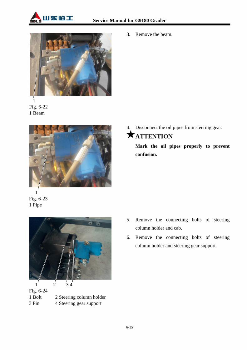
3. Remove the beam.
4. Disconnect the oil pipes from steering gear.
ATTENTION
Mark the oil pipes properly to prevent
confusion.
5. Remove the connecting bolts of steering
column holder and cab.
6. Remove the connecting bolts of steering
column holder and steering gear support.
1
Fig. 6-22
1 Beam
1 2 3 4
Fig. 6-24
1 Bolt 2 Steering column holder
3 Pin 4 Steering gear support
1
Fig. 6-23
1 Pipe

Service Manual for G9180 Grader
6-16
7. Remove the connecting bolts of steering
column and steering gear. Take down the
steering gear.
8. Remove the straight joints.
Assembly of steering gear
1. Install the straight joints to the corresponding
oil ports.
2. Connect steering column and steering gear
with four M10×25 bolts and gaskets.
3. Install the pin to connect the steering column
holder and steering gear support.
4. Install the steering column holder to cab with
four M10×25 bolts and gaskets.
1 2
Fig. 6-25
1 Bolt 2 Straight joint
1 2 3
Fig. 6-27
1 Bolt 2 Steering column holder
3 Pin
1 2 3 4
Fig. 6-26
1 Steering column 2 Bolt
3 Gasket 3 Steering gear support

Service Manual for G9180 Grader
6-17
5. Connect the oil pipes to the corresponding oil
ports of steering gear.
6. Install the beam fixing bolts.
7. Install the top guard plate.
1
Fig. 6-29
1 Beam
Fig. 6-28
1 2
Fig. 6-30
1 Bolt 2 Top guard plate

Service Manual for G9180 Grader
6-18
8. Install the left and right guard plates.
624 Steering Control Mechanism Assembly
Fig. 6-32
1 Steering wheel 2 Steering column 3 Nut 4 Gasket
5 Pressing plate 6 Protective cover 7 Steering column holder 8 Cotter pin
9 Gasket 10 Bolt 11 Steering gear support 12 Pin
1
Fig. 6-31
1 Left guard plate

Service Manual for G9180 Grader
6-19
625 Front Axle
Fig. 6-33 Front axle assembly
1 Front axle 2 Gasket 3 Bolt 5 Rim 6 Oil cup 7 Lock washer
8 V-shape seal ring 9 Swing shaft 10 Bolt 11 Gasket 12 Support
Fig. 6-34 Front axle
1 Left steering frame 2 Left steering knuckle 3 Retainer ring 4 Shaft 5 Retainer ring
6 Front wheel tilt cylinder 7 Oil cup 8 Connecting rod 9 Retainer ring
10 Knuckle bearing 11 Bolt 12 Gasket 13 Support 14 Articulated shaft
15 Composite bearing 16 Cotter 17 Front axle frame 18 Lock washer
19 Composite bearing 20 Articulated shaft 21 Support 22 Gasket 23 Bolt
24 Screw 25 Gasket 26 Screw 27 Cover plate 28 Screw 29 Gasket 30 Pin
31 Right steering knuckle 32 Gasket 33 Gasket 34 Gasket 35 Right steering frame
Front axle bracket

Service Manual for G9180 Grader
6-20
36 Wheel axle 37 V-shape seal ring 38 Seal ring 39 Screw 40 Hub cover
41 O-ring 42 Nut 43 Lock washer 44 Gasket 45 Tapered roller bearing
46 Screw 47 Screw 48 Hub 49 Gasket 50 Lining 51 Nut 52 Right swivel head
53 Lock nut 54 Cotter 55 Left swivel head 56 Clamp 57 Nut
58 Bolt 59 Pull rod 60 Shaft 61 Pin 62 Plain radial bearing 63 Retainer ring
64 Plate 65 Right steering cylinder 66 Bolt 67 Articulated shaft
68 Support 69 Left steering cylinder
The front axle assembly of grader is different from common axle. Apart from having steering
function, it also has front-wheel wide-angle tilting function and horizontal swing function. Because
of the design, the grader can balance itself during working, and the working accuracy is improved.
Under special working condition, it can increase adhesive force of the front wheels, which is
beneficial for the grader to satisfy all kinds of working conditions.
Maintenance of front wheel bearing must be conducted by specialized person in accordance with
specific procedures. Non-specialized person is not allowed to disassemble the front axle.
Disassembly of front axle assembly
1. Put the machine in maintenance position.
2. Start the engine, and operate the control handle
of the shovel blade rotary cylinder until the
blades are perpendicular to the front frame.
And then operate the control handle of the
shovel blade lifting cylinder to lower the
blades to the prepared wood support. Shut
down the engine.
ATTENTION
Before performing the following
maintenance work, you must prop up the
shovel blades. Otherwise the grader may tip
over and cause personnel injury.
1
Fig. 6-35
1 Shovel blade

Service Manual for G9180 Grader
6-21
Removal of front wheel
1. Loosen the fixing bolts of front wheels. Start
the engine and operate the control handle of
the shovel blade lifting cylinder to lower the
blades, in this case, the front end of grader is
elevated. Put reliable support under the front
end of the grader and operate the control
handle of the shovel blade lifting cylinder to
lift the blades, to let the front end of the grader
fall on the support slowly. Shut down the
engine.
2. Remove the fixing bolts of front wheels, take
down the bolts and gaskets. Remove the
wheels.
Removal of front wheel hub
1. Hang the hub with lifting appliance, remove
the fixing bolts of the hub cover, take down
the bolts and hub cover.
Hub
2. Remove the O-ring from the hub cover.
1 2
Fig. 6-37
1 Hub cover 2 Inside hexagon bolt
1 2
Fig. 6-38
1 Hub cover 2 O-ring
1
Fig. 6-36
1 Bolt

Service Manual for G9180 Grader
6-22
3. Remove the outside lock nut, and then take
down the lock nut, lock washer, and the lock
nut and gasket under the washer.
4. Use special tool to remove the hub.
ATTENTION
In the process of removing the hub, the
tapered roller bearing may fall off at any
moment.
Structurally, middle part of the wheel axle
is lower, so do not knock to remove the hub,
to avoid damaging the tapered roller
bearing.
Fig. 6-41
1 2 3 4 5
Fig. 6-39
1 Hub 2 Gasket 3 Lock nut
4 Lock washer 5 Lock nut
1
Fig. 6-40
1 Tapered roller bearing

Service Manual for G9180 Grader
6-23
5. Use special tool to remove the tapered roller
bearing. Take down the V-shape seal ring and
O-ring.
Removal of drag link
1. Hang the drag link with lifting appliance, and
then remove the cotter pin.
2. Screw off the slotted nut, and take down the
nut and gasket.
1 2 3
Fig. 6-42
1 Tapered roller bearing
2 V-shape seal ring 3 O-ring
1 2 3 4
Fig. 6-43
1 Cotter pin 2 Slotted nut
3 Gasket 4 Drag link

Service Manual for G9180 Grader
6-24
3. Use copper bar to knock the swivel head off
(knock from bottom).
4. Do the same to the swivel head on the other
end, and then lift down the drag link.
5. Remove the fixing bolt of the clamp, take
down the clamp and separate the swivel head
and drag link.
Removal of steering cylinder
1. Disconnect the oil pipes from the steering
cylinder.
1
Fig. 6-44
1 Swivel head
1
Fig. 6-45
1 Clamp
1
Fig. 6-46
1 Oil pipe

Service Manual for G9180 Grader
6-25
2. Remove the fixing bolt of the steering cylinder
piston-side connecting pin, take down the bolt,
gasket and the bottom support. Then use a
copper bar to remove the pin.
3. Remove the cotter pin from the slotted nut, and
then screw off the slotted nut. Take down the
nut and gasket.
4. Use a copper bar to knock the swivel head off
the steering frame.
5. Lift down the steering cylinder. Remove the
connecting bolt of the swivel head and steering
cylinder piston rod, and take down the swivel
head.
1
Fig. 6-47
1 Bolt
1
Fig. 6-48
1 Slotted nut
1
Fig. 6-49
1 Bolt

Service Manual for G9180 Grader
6-26
Removal of wheel axle
1. Remove the connecting bolts of the wheel axle
and steering frame, and then take down the
wheel axle.
Wheel axle
Removal of steering frame
1. Remove the fixing bolts of the cover plate,
take down the bolts and cover plate.
2. Remove the inside hexagon bolt, take down
the bolt and gasket.
1 2
Fig. 6-51
1 Cover plate 2 Bolt
1
Fig. 6-50
1 Bolt
1
Fig. 6-52
1 Inside hexagon bolt

Service Manual for G9180 Grader
6-27
3. Remove the pin.
4. Use the same method to disconnect the other
end connection, lift the steering frame away.
Steering frame
Removal of front wheel tilt cylinder
1. Hang the tilt cylinder with lifting appliance.
2. Disconnect the oil pipes from the tilt cylinder.
3. Remove the fixing bolt of the tilt cylinder
piston-side connecting pin, take down the bolt
and gasket. Then use special tool to remove
the pin.
1 2 3
Fig. 6-54
1 Tilt cylinder rod-side connecting hose
2 Tilt cylinder piston-side rubber hose
1
Fig. 6-53
1 Pin
1
Fig. 6-55
1 Bolt

Service Manual for G9180 Grader
6-28
4. Use snap ring plier to remove the snap ring of
tilt cylinder rod-side connecting pin. Then use
a copper bar to remove the pin. Lift the tilt
cylinder away.
Front wheel tilt cylinder
Removal of connecting rod
1. Use snap ring plier to remove the snap ring on
both ends of the pin.
2. Use the same method to remove the snap rings
on the other end of the connecting rod. Hang
the connecting rod away with lifting appliance.
Connecting rod
3. Use snap ring plier to remove the snap ring.
Then remove the connecting pin(s).
1
Fig. 6-57
1 Snap ring
1
Fig. 6-56
1 Snap ring
1
Fig. 6-58
1 Snap ring

Service Manual for G9180 Grader
6-29
Removal of steering knuckle
1. Remove the fixing bolt of steering knuckle and
front axle bracket connecting pin, take down
the bolt and gasket. Use special tool to remove
the connecting pin, and lift the steering
knuckle away.
Steering knuckle
Removal of front axle bracket
1. Remove the fixing bolt of front axle bracket
and frame connecting pin, take down the bolt
and gasket.
2. Use special tool to remove the connecting pin,
and lift the front axle bracket away.
Front axle bracket
1
Fig. 6-60
1 Bolt
1
Fig. 6-59
1 Bolt

Service Manual for G9180 Grader
6-30
Assembly of front axle assembly
Assembly of front axle bracket
1. Hang the front axle bracket with lifting
appliance, align it to the frame for assembling,
and then install the pin to connect them.
Front axle bracket
2. Install the pin fixing bolt and gasket.
Assembly of steering knuckle
1. Hang the steering knuckle with lifting
appliance, align it to the front axle bracket for
assembling, and then install the pin to connect
them.
Steering knuckle
2. Install the pin fixing bolt and gasket.
1
Fig. 6-61
1 Bolt
1
Fig. 6-62
1 Bolt

Service Manual for G9180 Grader
6-31
Assembly of connecting rod
1. Preassemble the two connecting pins to the
steering knuckle first, and install the snap
rings.
2. Install the knuckle bearing to the pin, and fix it
with snap ring.
3. Hang the connecting rod with lifting appliance,
align it to the steering knuckle for assembling,
connect them with the two preassembled pins,
and install the snap rings.
Connecting rod
Assembly of front wheel tilt cylinder
1. Lift the tilt cylinder to suitable position for
assembling.
Front wheel tilt cylinder
2. Install the cylinder piston-side connecting pin,
and fix the pin with bolt and gasket.
3. Install the cylinder rod-side connecting pin and
fix the pin with snap ring.
1 2
Fig. 6-63
1 Pin 2 Snap ring
1
Fig. 6-64
1 Bolt
1
Fig. 6-65
1 Snap ring

Service Manual for G9180 Grader
6-32
4. Connect the piston-side and rod-side rubber
hoses.
Assembly of steering frame
1. Hang the steering frame with lifting appliance,
align it to the steering knuckle for assembling,
and then install the pin to connect them.
Steering frame
2. Install the inside hexagon bolt.
1 2 3
Fig. 6-66
1 Tilt cylinder rod-side connecting hose
2 Tilt cylinder piston-side rubber hose
1
Fig. 6-67
1 Pin
1 2
Fig. 6-68
1 Inside hexagon bolt 2 Gasket

Service Manual for G9180 Grader
6-33
3. Install the fixing bolts of the cover plate.
Assembly of wheel axle
1. Use lifting appliance to lift the wheel axle to
suitable position for assembling. Then install
the connecting bolts of the wheel axle and
steering frame.
Wheel axle
Assembly of steering cylinder
1. Connect the steering cylinder to the swivel
head with bolt.
2. Use lifting appliance to lift the steering
cylinder assembly to suitable position for
assembling. Then connect the swivel head to
the steering frame.
1
Fig. 6-70
1 Bolt
1 2
Fig. 6-69
1 Cover plate 2 Bolt
1
Fig. 6-71
1 Bolt

Service Manual for G9180 Grader
6-34
3. Tighten the slotted nut to fix the swivel head.
Then install the cotter to fix the nut.
4. Install the fixing bolt of the steering cylinder
piston-side connecting pin.
5. Connect the oil pipes to the steering cylinder.
1
Fig. 6-72
1 Slotted nut
1
Fig. 6-73
1 Bolt
1
Fig. 6-74
1 Oil pipe

Service Manual for G9180 Grader
6-35
Assembly of drag link
1. Install the clamp to connect the swivel head
and drag link.
2. Use lifting appliance to lift the drag link to
suitable position for assembling. Then connect
the swivel head to the steering frame.
3. Tighten the slotted nut to fix the swivel head.
Then install the cotter to fix the nut.
1
Fig. 6-75
1 Clamp
1 2 3
Fig. 6-77
1 Cotter pin 2 Slotted nut
3 Gasket
1
Fig. 6-76
1 Drag link
Service Manual for G9180 Grader
6-36
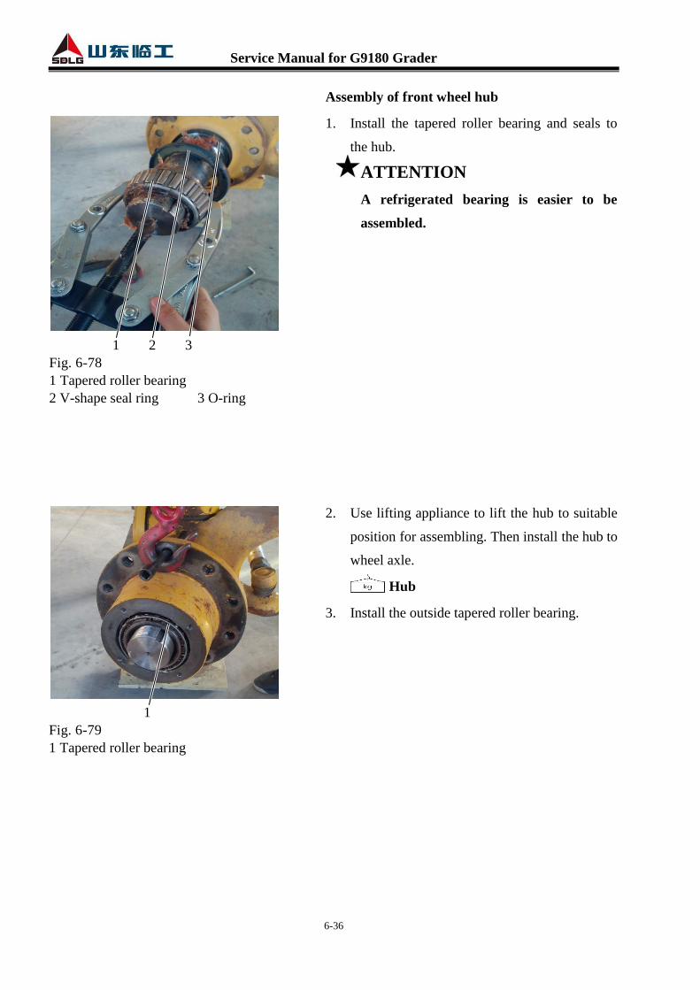
Assembly of front wheel hub
1. Install the tapered roller bearing and seals to
the hub.
ATTENTION
A refrigerated bearing is easier to be
assembled.
2. Use lifting appliance to lift the hub to suitable
position for assembling. Then install the hub to
wheel axle.
Hub
3. Install the outside tapered roller bearing.
1
Fig. 6-79
1 Tapered roller bearing
1 2 3
Fig. 6-78
1 Tapered roller bearing
2 V-shape seal ring 3 O-ring

Service Manual for G9180 Grader
6-37
4. Install the gasket, lock nut, lock washer and
the outside lock nut orderly.
5. Install the O-ring from the hub cover. Then
install the hub cover to wheel hub.
6. Install and tighten the fixing bolts of the hub
cover.
1 2
Fig. 6-82
1 Hub cover 2 Inside hexagon bolt
1 2 3 4 5
Fig. 6-80
1 Hub 2 Gasket 3 Lock nut
4 Lock washer 5 Lock nut
1 2
Fig. 6-81
1 Hub cover 2 O-ring

Service Manual for G9180 Grader
6-38
Assembly of front wheel
1. Use bolts and nuts to fix the wheel on hub.
Wheel
626 Steering Cylinder
Single-rod double-acting hydraulic cylinder
Technical parameters
Cylinder diameter 63mm
Piston rod diameter 45mm
Piston stroke 340mm
Fig. 6-84 Steering cylinder
1
Fig. 6-83
1 Bolt

Service Manual for G9180 Grader
6-39
63 Pressure Measurement of Steering Hydraulic System
Pressure measuring tools
Pressure gauge with measuring range of 0~25MPa
Pressure measuring points
Quick pressure measuring joints on steering cylinder (Specification of thread on the port M16×2)
Fig. 6-85 Steering system pressure measuring point
Pressure measuring method
1. Connect the pressure gauge to the pressure measuring joint.
2. Start the engine and turn the steering wheel to the extreme position to build pressure.
3. Read and record the reading on pressure gauge.
Standard working hydraulic system pressure
Set pressure of steering system: 140±3.5Bar.
Steering system pressure measuring point
Service Manual for G9180 Grader
6-40
64 Deflation of Steering Hydraulic System
After replacing steering pump, steering gear, priority valve, steering cylinder and the hydraulic
pipes in steering circuit, air bleeding must be done by performing the following steps:
1. Park the loader in maintenance position properly, lower the front bulldozing plate to the ground
and jack up the front wheel (off ground), and then open the filling cap of hydraulic oil tank.
2. Start and run the engine idly, turn the steering wheel gently to let steering cylinders stretch out
and draw back (about 50~60mm, from the bottom of the stroke) for 2~3 times.
3. After the hydraulic oil is fully circulated, turn the steering wheel left and right within a narrow
range for several times. Be sure not to let the steering cylinder gets to its stroke end.
4. Keep the engine run at high speed, turn the steering wheel gently to let steering cylinders
stretch out and draw back in full stroke for 3~5 times to drain the air in the circuit out.
5. After air bleeding, set the machine and working device in standard position (the steering wheel
should be in neutral position; front frame and rear frame should be in the same line; the front
bulldozing plate should be lower to ground and be 90o to the frame; the scarifier should be
lowered close to the ground). Then check the oil level and tighten the filling cap.
6. Stop the engine, check and ensure there is no leakage in hydraulic circuit.

Service Manual for G9180 Grader
6-41
65 Diagnosis and Solutions for Common Faults of Steering System
Table 6-2 Fault phenomenon and elimination methods
1. Steering hard
1. The built-in check valve of steering gear is damaged and the
inlet is blocked.
2. Steering gear failure, the check valve steel ball is jammed and
couldn’t reset.
3. Priority valve LS pipe is twisted together or too long, the
damping hole is blocked or oil leakage.
4. The steering column is damaged and requires larger driving
torque.
5. Interference between steering column and steering gear
connecting part, extra axial or radial force is formed and acts
on steering gear valve element after assembling.
6. Low set pressure of priority valve relief valve, or the main
valve element is stuck, or the damping hole is blocked.
7. Low set pressure of safety valve of steering gear combination
valves.
8. Oil return filter is blocked.
9. The pump is severely worn, whose volume efficiency, output
pressure and flow rate can no longer meet system requirement.
10. Somewhere in the steering circuit is blocked that results in
severe throttle.
11. Main valve element of priority valve is jammed or the main
spring rigidity is reduced.
12. Interference in front axle steering mechanism.
2. Vehicle snaking
1. Check for cavitation phenomenon.
2. The pump oil absorption steel pipe or pipe joint has air leakage
problem.
3. Low oil level in hydraulic oil tank.
4. Steering cylinder connecting pin is loose or the piston rod is
distorted.
5. Steering cylinder has severe internal leakage problem.
6. The bi-directional overload valve or bi-directional refill valve
has oil leakage problem

Service Manual for G9180 Grader
6-42
3. Vehicle off tracking
1. Check whether the connecting rod of steering cylinder is loose.
2. Internal leakage of steering cylinder.
3. There is large pressure differential between the two tires.
4. Leakage in one side of bi-directional oil compensation valve or
bi-directional overload valve.
5. Oil contains too much air.
4. Self-steering when
steering wheel is in
neutral.
1. Check the connecting rod of steering cylinder is loose.
2. Internal leakage of steering cylinder.
3. Leakage in one side of bi-directional oil compensation valve or
bi-directional overload valve.
4. Oil contains too much air.
5. Transient steering is not
flexible after the machine
is just started.
1. The machine is off work for too long, large temperature
differential between steering gear components and hydraulic
oil.
6. Steering is inaccurate.
1. Too much air in the steering system.
2. Steering cylinder pin is loose.
3. Heat shock.
4. Main valve element of priority valve is jammed.
5. Oil leakage in steering cylinder.
6. Low efficiency of steering pump results in unstable pressure.
7. Steering cylinder
creeping 1. Too much air in the steering system.
8. Steering wheel can be
turned freely, but there is
no force feeling or the
machine fails to steer.
1. Nuts of steering wheel and steering column fall off.
2. The connection between steering column central spindle and
steering gear valve element is failed.
3. Low hydraulic oil level.
9. Steering wheel can be
turned easily, but the
machine doesn’t steer or
steers slowly.
1. Severe leakage in bi-directional oil compensation valve or
bi-directional overload valve.
2. Severe internal leakage of steering cylinder.

Service Manual for G9180 Grader
6-43
10. Idle motion of steering
wheel.
1. Nut of steering wheel is loose.
2. The connection between steering column and steering gear is
severely worn or damaged.
3. Oil contains too much air.
4. Leakage in bi-directional oil compensation valve or
bi-directional overload valve.
5. The steering cylinder linkage is damaged or worn (big gap).
6. Leakage of steering cylinder.
11. Bad return or dragging
turning of steering wheel
1. The connection between steering column and steering gear is
too tight or interference exists.
2. Too large return backpressure results in bad return.
3. Big contamination particle enters into the gap between valve
bush and valve element that results in unable to return.
4. Steering gear spring sheet is damaged or with small rigidity.
12. Components of steering
gear is damaged
1. Big and hard contamination particle enters into the gap between
stator and rotor.
2. Severe grind damage.
3. Pull pin cracked
4. Heat shock. (50oC differential)
13. Steering wheel trembles
or self-rotation
1 Wrong assembly relationship. For reassembly, corresponding
spline tooth in universal driving shaft pull pin groove should be
aligned to rotor internal spline tooth concave.
2 Connect the oil inlet pipe to port R or port L, and the steering
gear will self-rotate as the motor.
14. Steering wheel and the
machine turning in
opposite direction
1. Pipe of port L and port R are inversely connected.
15. Steering wheel rebound 1. The built-in check valve of steering gear is damaged