6QM Solution for IPv6 QoS Measurements · IPv4 vs IPv6 Results IPv6 172.2 14.6 166.7 4.2 IPv4 137.7...
19
6QM Solution for IPv6 QoS Measurements Nov. 2004 Moscow Jordi Palet (Consulintel), César Olvera (Consulintel), Miguel A. Díaz (Consulintel) {jordi.palet, cesar.olvera, miguelangel.diaz}@consulintel.es
Transcript of 6QM Solution for IPv6 QoS Measurements · IPv4 vs IPv6 Results IPv6 172.2 14.6 166.7 4.2 IPv4 137.7...
6QM Solution forIPv6 QoS Measurements
Nov. 2004Moscow
Jordi Palet (Consulintel), César Olvera (Consulintel),Miguel A. Díaz (Consulintel)
{jordi.palet, cesar.olvera, miguelangel.diaz}@consulintel.es
RIPE 49 Meeting2
Introduction• The QoS measurement system is a key element to verify the QoS
available within networks. There are not many products availablewhich support IPv6 QoS measurement, so the prototype systemdeveloped by the IST project 6QM (IPv6 QoS Measurement) aims tobe a good reference for this kind of products.
• This presentation describes:– Main characteristics of 6QM OpenIMP prototype, which is pretty fully
operational according to its specifications for measurements on Passiveonly, Active only and Passive and Active combined modes.
– Some key characterization tests and results done to prototype in order toprovide to the users the confidence in its results and not overcome itslimits.
– Finally, an on-line demonstration including several 6QM probes,deployed in Europe and Japan is done.
RIPE 49 Meeting3
Measurement System Overview
• The Measurement System is called “OpenIMP” and it is able tomeasure several QoS parameters within IPv6 networks– It is software developed for both Linux and FreeBSD OSs
• It introduces new concepts on the measurement field. Some ofthe more relevant features are the following:– support for IPv6 traffic, even 6in4 tunneled traffic– passive only mode– active only mode– passive and active combined mode– interdomain measurements
• It makes reports about the commonest QoS parameters likeloss, one way delays etc, so it is a good tool to know the realQoS in the network
RIPE 49 Meeting4
Functional Architecture
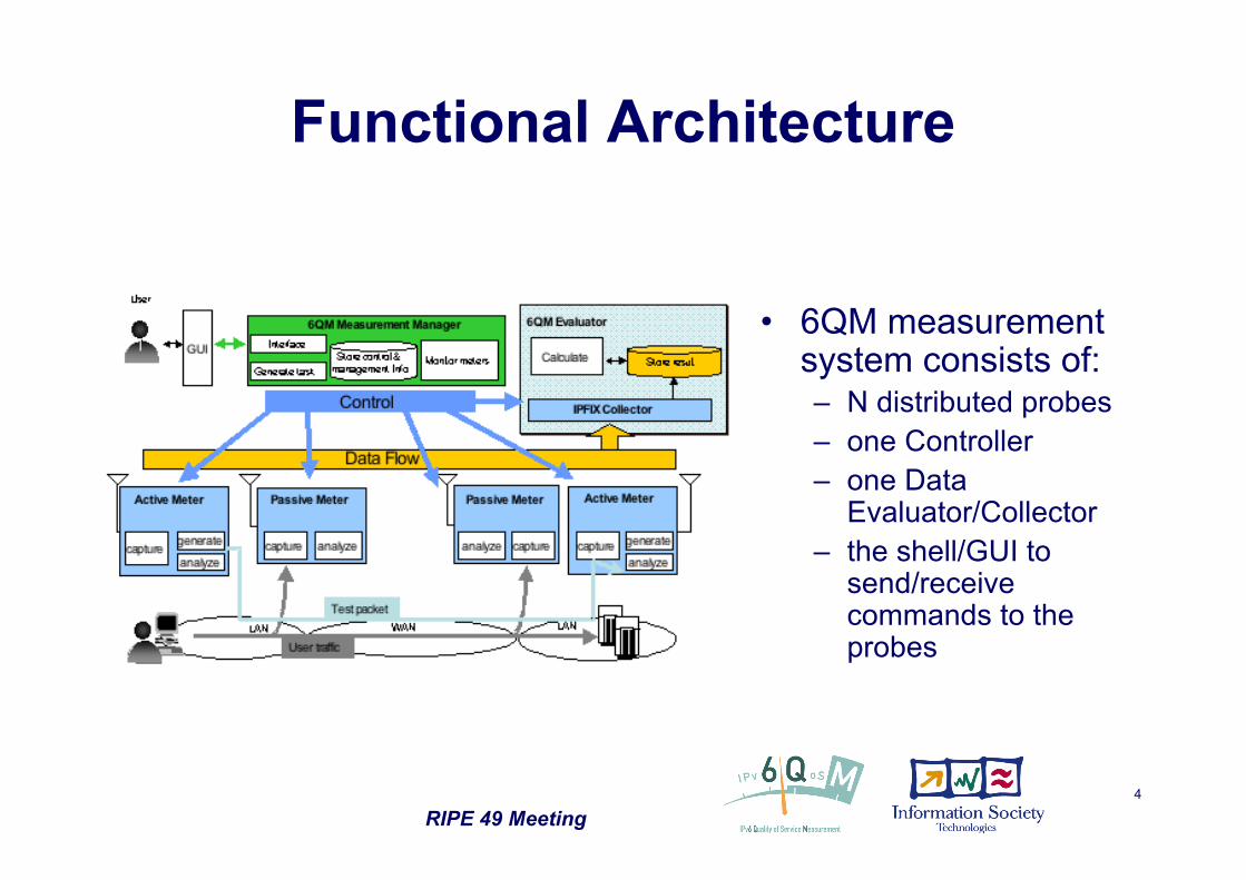
• 6QM measurementsystem consists of:– N distributed probes– one Controller– one Data
Evaluator/Collector– the shell/GUI to
send/receivecommands to theprobes
RIPE 49 Meeting5
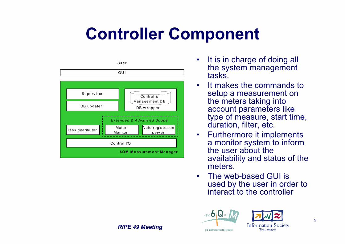
Controller Component
6QM M e as urem en t M an ager
Meter
Monitor
Superv is or
GU I
Us er
Tas k d is tr ibutor
Contro l I/O
DB updater
Contro l &
Manage ment D B
DB w rapper
A uto-reg is tration
s erv er
Ex tended & Advanc ed Sc ope
• It is in charge of doing allthe system managementtasks.
• It makes the commands tosetup a measurement onthe meters taking intoaccount parameters liketype of measure, start time,duration, filter, etc.
• Furthermore it implementsa monitor system to informthe user about theavailability and status of themeters.
• The web-based GUI isused by the user in order tointeract to the controller
RIPE 49 Meeting6
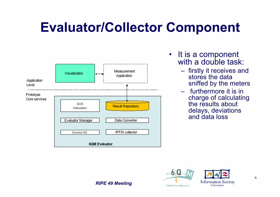
Evaluator/Collector Component
• It is a componentwith a double task:– firstly it receives and
stores the datasniffed by the meters
– furthermore it is incharge of calculatingthe results aboutdelays, deviationsand data loss
RIPE 49 Meeting7
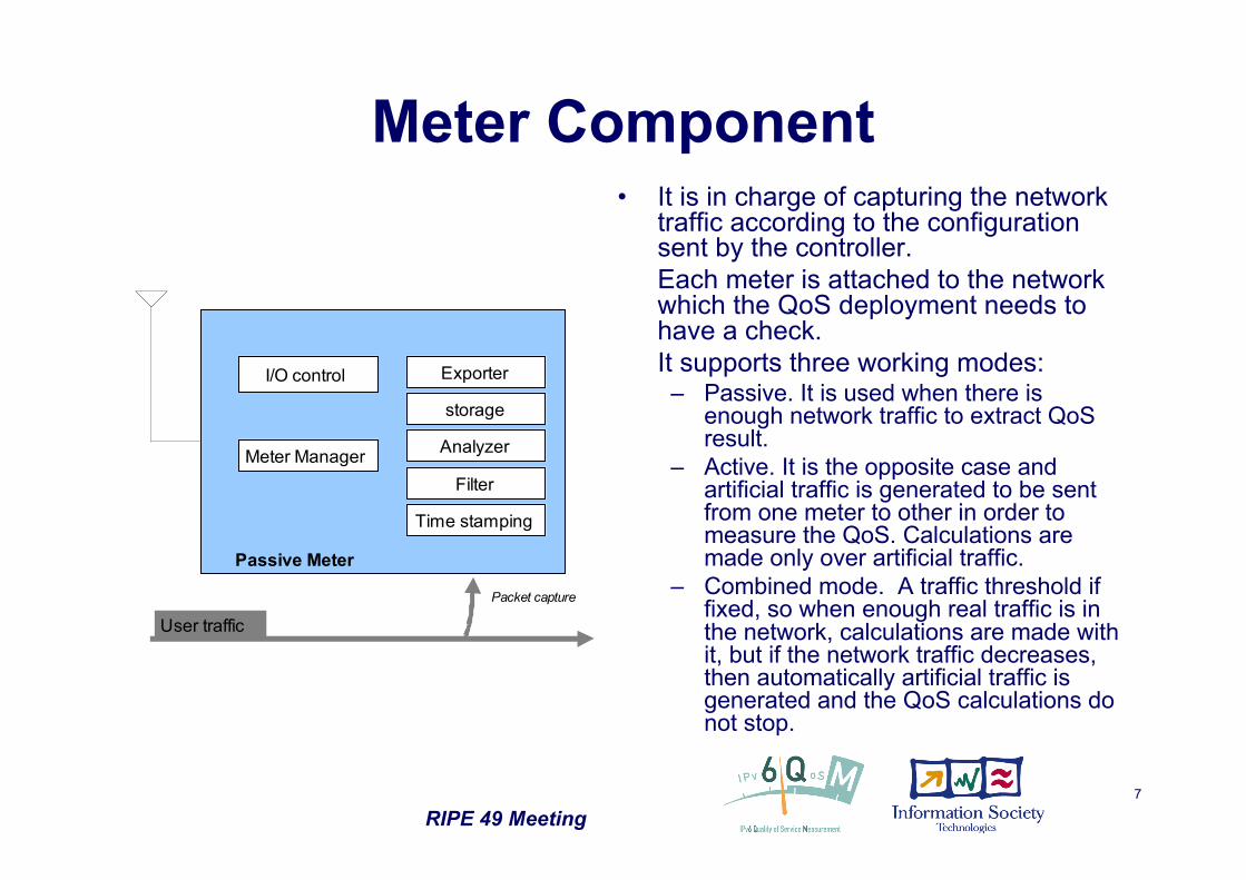
Meter Component• It is in charge of capturing the network
traffic according to the configurationsent by the controller.
• Each meter is attached to the networkwhich the QoS deployment needs tohave a check.
• It supports three working modes:– Passive. It is used when there is
enough network traffic to extract QoSresult.
– Active. It is the opposite case andartificial traffic is generated to be sentfrom one meter to other in order tomeasure the QoS. Calculations aremade only over artificial traffic.
– Combined mode. A traffic threshold iffixed, so when enough real traffic is inthe network, calculations are made withit, but if the network traffic decreases,then automatically artificial traffic isgenerated and the QoS calculations donot stop.
I/O control
Time stamping
Analyzer
Passive Meter
User traffic
Filter
storage
Meter Manager
Packet capture
Exporter
RIPE 49 Meeting8
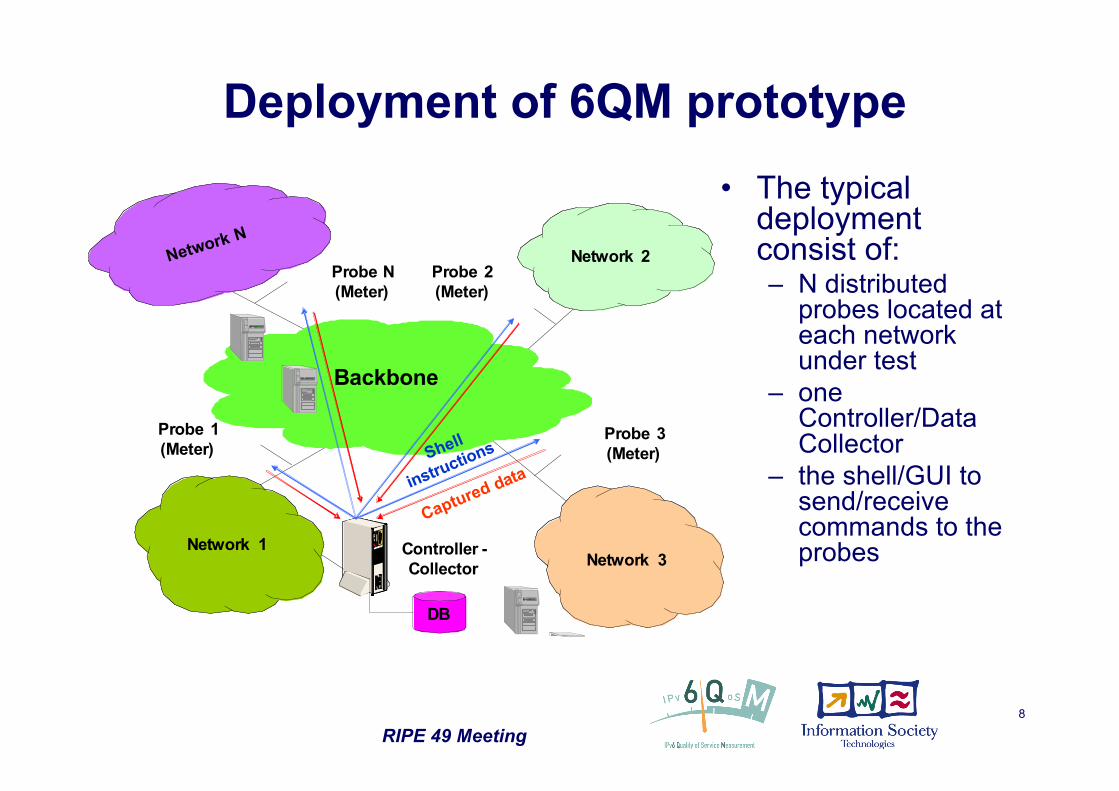
Deployment of 6QM prototype• The typical
deploymentconsist of:– N distributed
probes located ateach networkunder test
– oneController/DataCollector
– the shell/GUI tosend/receivecommands to theprobes
Network 2
Network 3
Network N
Backbone
Probe 3
(Meter)
Probe 2
(Meter)
Probe 1
(Meter)
Network 1
DB
Controller -
Collector
Captured data
Shell
instructions
Probe N
(Meter)
RIPE 49 Meeting9
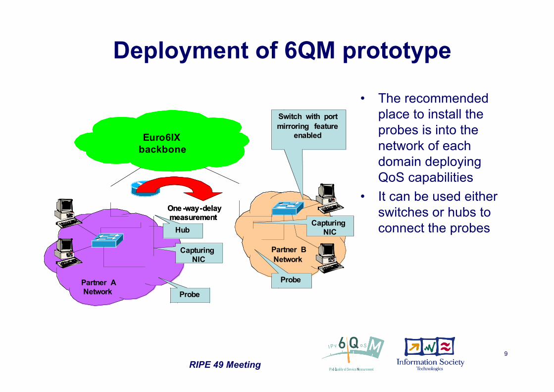
Deployment of 6QM prototype
• The recommendedplace to install theprobes is into thenetwork of eachdomain deployingQoS capabilities
• It can be used eitherswitches or hubs toconnect the probes
Euro6IX
backbone
One -way-delay
measurement
Partner A
Network
Partner B
Network
Probe
Probe
Hub
Capturing
NIC
Switch with port
mirroring feature
enabled
Capturing
NIC
Euro6IX
backbone
Euro6IX
backbone
One -way-delay
measurement
Partner A
Network
Partner B
Network
Probe
Probe
Hub
Capturing
NIC
Switch with port
mirroring feature
enabled
Capturing
NIC
RIPE 49 Meeting10
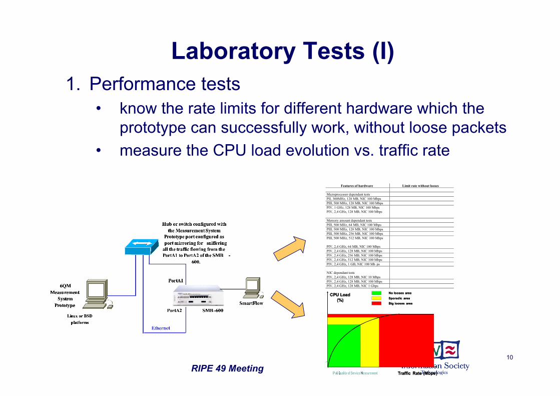
Laboratory Tests (I)1. Performance tests
• know the rate limits for different hardware which theprototype can successfully work, without loose packets
• measure the CPU load evolution vs. traffic rate
CPU Load
(%)
Traffic Rate (Mbps)
No looses area
Sporadic area
Big looses area
CPU Load
(%)
Traffic Rate (Mbps)
No looses area
Sporadic area
Big looses area
Features of hardware Limit rate without looses
Microprocessor dependant tests
PII, 300MHz, 128 MB, NIC 100 Mbps
PIII, 500 MHz, 128 MB, NIC 100 Mbps
PIV, 1 GHz, 128 MB, NIC 100 Mbps
PIV, 2,4 GHz, 128 MB, NIC 100 Mbps
Memory amount dependant tests
PIII, 500 MHz, 64 MB, NIC 100 Mbps
PIII, 500 MHz, 128 MB, NIC 100 Mbps
PIII, 500 MHz, 256 MB, NIC 100 Mbps
PIII, 500 MHz, 512 MB, NIC 100 Mbps
PIV, 2,4 GHz, 64 MB, NIC 100 Mbps
PIV, 2,4 GHz, 128 MB, NIC 100 Mbps
PIV, 2,4 GHz, 256 MB, NIC 100 Mbps
PIV, 2,4 GHz, 512 MB, NIC 100 Mbps
PIV, 2,4 GHz, 1 GB, NIC 100 Mb ps
NIC dependant tests
PIV, 2,4 GHz, 128 MB, NIC 10 Mbps
PIV, 2,4 GHz, 128 MB, NIC 100 Mbps
PIV, 2,4 GHz, 128 MB, NIC 1 Gbps
RIPE 49 Meeting11
Laboratory Tests (II)2. Influence of number of filtering rules in the meter
• check if the performance of the meter can beinfluenced by the complexity of the rule
• make different tests with different rules to see howthey affect the performance
3. Header fields tests• check if the prototype can be considered fully
IPv4/IPv6 compliant• the goal is to identify possible bugs in the software
that led the system badly work with any configuration4. Influence of BW used for data export for given
some configuration
RIPE 49 Meeting12
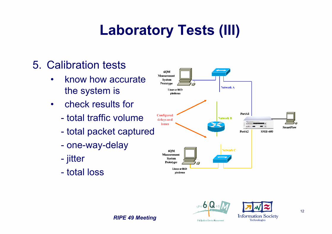
Laboratory Tests (III)
5. Calibration tests• know how accurate
the system is• check results for
- total traffic volume- total packet captured- one-way-delay- jitter- total loss
RIPE 49 Meeting13
Real Networks Tests• After the laboratory tests, the next step is to
deploy and evaluate the 6QM prototype into areal native IPv6 networks in order to know all theissues related to its use in the field
• The goal is to get information for evaluate andvalidate the prototype in addition of generateinitial data on QoS parameters and status of theIPv6 networks that participate in the deployment
RIPE 49 Meeting14
Public Trials or Demonstrators• Successful external trails at
• IST 2002 in October 2002• CeBIT in February 2003• Madrid 2003 Global IPv6 Summit in May 2003• 6NET Spring 2004 Conference & Eurov6 Showcase in May 2004
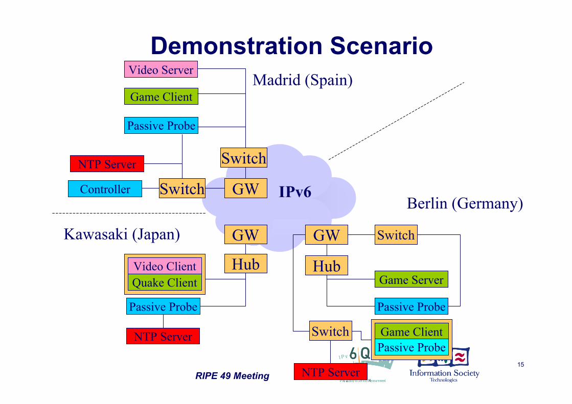
• “Fairness for Online Gaming: Distributed QoS Measurements forIPv6”, among Germany, Japan and Spain, using native IPv6 networksas Euro6IX, 6NET, BELNET, WIDE and others as 6Bone• Quake2 patched for IPv6 and IPv6 video streaming. All these itemswere jointly used with 6QM measurement probes distributed inBrussels, Berlin, Japan and Madrid
• IST2004, November 2004
RIPE 49 Meeting15
IPv6
Madrid (Spain)
GW
Game Client
Passive Probe
NTP Server
Video Server
Controller Switch
Passive Probe
NTP Server
Hub
GW GW
HubGame Server
Passive Probe
Switch
Game ClientPassive Probe
Switch
NTP Server
Switch
Quake ClientVideo Client
Berlin (Germany)
Kawasaki (Japan)
Demonstration Scenario
RIPE 49 Meeting16
Meters Synchronization
• As distributed measurement point has been considered, it wascrucial good synchronization among them to have coherenttime measurements
• Due to the high distance among the measurement points, it wasneeded to use independent time sources– Spanish site: the synchronization is performed by means of a
Stratum 1 NTP server connected to a GPS receiver via LANconnection.
– German site: a dedicated NTP server via LAN connection for themeasurement infrastructure is connected to a GPS receiver usingalso the receiver’s pulse-per-second signal.
– Japanese site: the passive meter is connected directly to aStratum 1 NTP server via a cross-cable.
• The achievable accuracy (in terms of a resulting clock offset)under these conditions can be established within the range ofsub-milliseconds
RIPE 49 Meeting17
Game Measurement Results
(1 )
(2 )
(3 )
(1 )
(2 )
(3 )
(1)
(2)
(3)
(1)
(2)
(3)
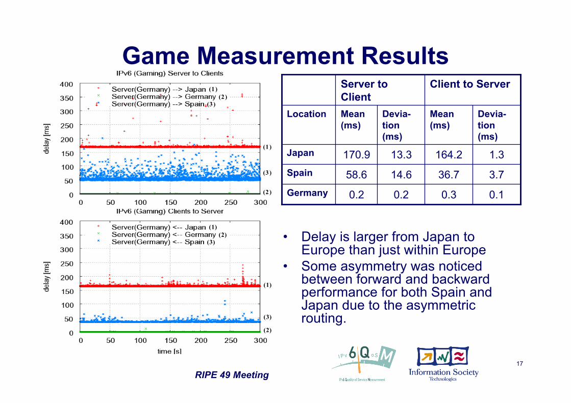
0.10.30.20.2Germany
3.736.714.658.6Spain
1.3164.213.3170.9Japan
Devia-tion(ms)
Mean(ms)
Devia-tion(ms)
Mean(ms)
Location
Client to ServerServer toClient
• Delay is larger from Japan toEurope than just within Europe
• Some asymmetry was noticedbetween forward and backwardperformance for both Spain andJapan due to the asymmetricrouting.
RIPE 49 Meeting18
IPv4 vs IPv6 Results
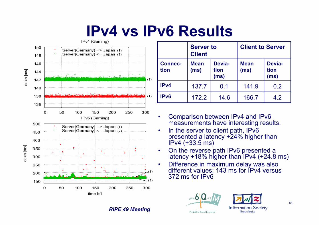
4.2166.714.6172.2IPv6
0.2141.90.1137.7IPv4
Devia-tion(ms)
Mean(ms)
Devia-tion(ms)
Mean(ms)
Connec-tion
Client to ServerServer toClient
• Comparison between IPv4 and IPv6measurements have interesting results.
• In the server to client path, IPv6presented a latency +24% higher thanIPv4 (+33.5 ms)
• On the reverse path IPv6 presented alatency +18% higher than IPv4 (+24.8 ms)
• Difference in maximum delay was alsodifferent values: 143 ms for IPv4 versus372 ms for IPv6
(1)
(2)
(1)
(2)
(1)
(2)
(1)
(2)
RIPE 49 Meeting19
Thanks !
• Questions?
• Acknowledgments:– David Diep (Hitachi)– Kiminori Sugauchi (Hitachi)– Guido Pohl (Fokus)