69-0740B - T8132 - Programmable Thermostat · 1 Welcome to the world of comfort and energy savings...
72
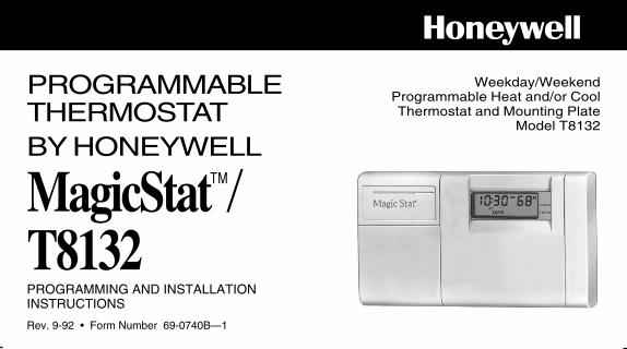
PROGRAMMABLE THERMOSTAT Honeywell Weekday/Weekend Programmable Heat and/or Cool Thermostat and Mounting Plate Model T8132 MagicStat / T8132 BY HONEYWELL Rev. 9-92 • Form Number 69-0740B—1 PROGRAMMING AND INSTALLATION INSTRUCTIONS
Transcript of 69-0740B - T8132 - Programmable Thermostat · 1 Welcome to the world of comfort and energy savings...
PROGRAMMABLETHERMOSTAT
Honeywell
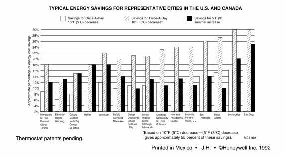
Thermostat patents pending.
Printed in Mexico • J.H. • ©Honeywell Inc. 1992
Weekday/WeekendProgrammable Heat and/or CoolThermostat and Mounting Plate
Model T8132
MagicStat/T8132
BY HONEYWELL
Rev. 9-92 • Form Number 69-0740B—1
PROGRAMMING AND INSTALLATIONINSTRUCTIONS
30%
28%
26%
24%
22%
20%
18%
16%
14%
12%
8%
6%
2%
10%
4%
MinneapolisSt. PaulMontrealOttawaToronto
BuffaloClevelandMilwaukee
EdmontonReginaWinnipeg
CalgaryMonctonNorth BayQuebecSt. John's
Halifax Vancouver DenverDes Moines OmahaSalt Lake City
BostonChicagoDetroitPittsburghIndianapolis
CincinnatiKansas CitySt. LouisColumbus
New YorkPhiladelphiaSeattle
LouisvillePortlandWash., D C
San Francisco
DallasAtlanta
Los Angeles
App
roxi
mat
e pe
rcen
tage
of e
nerg
y co
st s
avin
gs
Savings for Once-A-Day10°F (5°C) decrease
Savings for Twice-A-Day10°F (5°C) decrease*
Savings for 5°F (3°)summer increase
TYPICAL ENERGY SAVINGS FOR REPRESENTATIVE CITIES IN THE U.S. AND CANADA
*Based on 10°F (5°C) decrease—(5°F (3°C) decrease gives approximately 55 percent of these savings). M2416A
San Diego
1
Welcome to the world of comfort and energy savings with your new Honeywell MagicStatTM
programmable thermostat.Your new thermostat will automatically control the temperature in your home, keeping you
comfortable while saving energy when programmed according to the instructions in this manual.
Any questions concerning the application of this thermostat should be directed to HoneywellCustomer Assistance at 1-800-468-1502, Monday-Friday 7:00 a.m.-5:30 p.m., Central time.
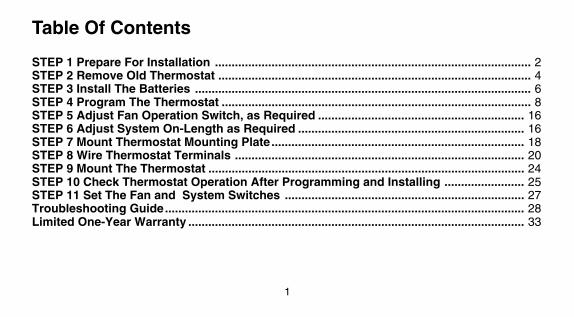
Table Of Contents
STEP 1 Prepare For Installation ............................................................................................... 2STEP 2 Remove Old Thermostat .............................................................................................. 4STEP 3 Install The Batteries ..................................................................................................... 6STEP 4 Program The Thermostat ............................................................................................. 8STEP 5 Adjust Fan Operation Switch, as Required .............................................................. 16STEP 6 Adjust System On-Length as Required .................................................................... 16STEP 7 Mount Thermostat Mounting Plate............................................................................ 18STEP 8 Wire Thermostat Terminals ....................................................................................... 20STEP 9 Mount The Thermostat ............................................................................................... 24STEP 10 Check Thermostat Operation After Programming and Installing ........................ 25STEP 11 Set The Fan and System Switches ........................................................................ 27Troubleshooting Guide............................................................................................................ 28Limited One-Year Warranty ..................................................................................................... 33
1
Welcome to the world of comfort and energy savings with your new Honeywell MagicStatTM
programmable thermostat.Your new thermostat will automatically control the temperature in your home, keeping you
comfortable while saving energy when programmed according to the instructions in this manual.
Any questions concerning the application of this thermostat should be directed to HoneywellCustomer Assistance at 1-800-468-1502, Monday-Friday 7:00 a.m.-5:30 p.m., Central time.
Table Of Contents
STEP 1 Prepare For Installation ............................................................................................... 2STEP 2 Remove Old Thermostat .............................................................................................. 4STEP 3 Install The Batteries ..................................................................................................... 6STEP 4 Program The Thermostat ............................................................................................. 8STEP 5 Adjust Fan Operation Switch, as Required .............................................................. 16STEP 6 Adjust System On-Length as Required .................................................................... 16STEP 7 Mount Thermostat Mounting Plate............................................................................ 18STEP 8 Wire Thermostat Terminals ....................................................................................... 20STEP 9 Mount The Thermostat ............................................................................................... 24STEP 10 Check Thermostat Operation After Programming and Installing ........................ 25STEP 11 Set The Fan and System Switches ........................................................................ 27Troubleshooting Guide............................................................................................................ 28Limited One-Year Warranty ..................................................................................................... 33

Prepare For Installation■■ Check Table 1 to make sure this thermostat is compatible with your system. If not, return toretailer. For more information, call Honeywell Customer Assistance, toll-free 1-800-468-1502.
TABLE 1—COMPATIBILITY CHART.System Type Compatible With CT3200
Gas—Standing Pilot YesGas—Electronic Ignition YesGas-Fired Boilers Yes 1Gas—Millivolt NoOil-Fired Boilers Yes 1Oil-Fired Furnace YesElectric Furnace YesElectric Air Conditioning YesBaseboard Electric (120/240 Line Volt) NoHeat Pumps/Multistage Equipment No
3
2
Not compatible with any 120/240 volt circuit.Will not work efficiently on steam or gravity systems.1 Compatible with 2-wire Honeywell zone valves. Isolating relay required for 3-wire thermo-stats for zone valves. Not compatible with 2-wire White-Rodgers #1361 valves.
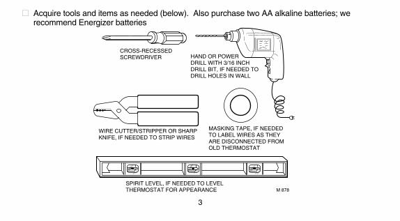
CROSS-RECESSEDSCREWDRIVER HAND OR POWER
DRILL WITH 3/16 INCHDRILL BIT, IF NEEDED TODRILL HOLES IN WALL
WIRE CUTTER/STRIPPER OR SHARPKNIFE, IF NEEDED TO STRIP WIRES
MASKING TAPE, IF NEEDEDTO LABEL WIRES AS THEYARE DISCONNECTED FROMOLD THERMOSTAT
SPIRIT LEVEL, IF NEEDED TO LEVELTHERMOSTAT FOR APPEARANCE M 878
■■ Acquire tools and items as needed (below). Also purchase two AA alkaline batteries; werecommend Energizer batteries
STEP 1
Prepare For Installation■■ Check Table 1 to make sure this thermostat is compatible with your system. If not, return toretailer. For more information, call Honeywell Customer Assistance, toll-free 1-800-468-1502.
TABLE 1—COMPATIBILITY CHART.System Type Compatible With CT3200
Gas—Standing Pilot YesGas—Electronic Ignition YesGas-Fired Boilers Yes 1Gas—Millivolt NoOil-Fired Boilers Yes 1Oil-Fired Furnace YesElectric Furnace YesElectric Air Conditioning YesBaseboard Electric (120/240 Line Volt) NoHeat Pumps/Multistage Equipment No
3
2
Not compatible with any 120/240 volt circuit.Will not work efficiently on steam or gravity systems.1 Compatible with 2-wire Honeywell zone valves. Isolating relay required for 3-wire thermo-stats for zone valves. Not compatible with 2-wire White-Rodgers #1361 valves.
CROSS-RECESSEDSCREWDRIVER HAND OR POWER
DRILL WITH 3/16 INCHDRILL BIT, IF NEEDED TODRILL HOLES IN WALL
WIRE CUTTER/STRIPPER OR SHARPKNIFE, IF NEEDED TO STRIP WIRES
MASKING TAPE, IF NEEDEDTO LABEL WIRES AS THEYARE DISCONNECTED FROMOLD THERMOSTAT
SPIRIT LEVEL, IF NEEDED TO LEVELTHERMOSTAT FOR APPEARANCE M 878
■■ Acquire tools and items as needed (below). Also purchase two AA alkaline batteries; werecommend Energizer batteries
STEP 1

4
5
Remove Old Thermostat
not compatible with such systems so returnthe product to the place of purchase. If youwould like information about which program-mable thermostats will work with your system,call Honeywell Customer Assistance at1-800-468-1502.
Three thermostat wires?If you have three wires for heating only and
can operate the fan using the fan ON switch,this thermostat will work with your system.However, some hot water (zoned) heatingsystems have three thermostat wires. Thethermostat will not work without installing anisolating relay on these systems. Call Honey-well Customer Assistance at 1-800-468-1502for details.
■■ Test to make certain that your heatingand cooling systems are working properly. Ifeither does not work, contact your local heating/air conditioning dealer. To avoid compressordamage, do not operate the cooling systemwhen outdoor temperature is below 10° C [50°F].■■ TURN OFF POWER to system at thefurnace, or at the fuse/circuit breaker panel.■■ Carefully unpack your new thermostat andmounting plate; save package of screws,instructions and receipt.■■ Remove cover from old thermostat. If it doesnot snap off when pulled firmly from the bottom,check for a screw used to lock on the cover.■■ Loosen screws holding thermostat to
subbase, wallplate or wall, and lift away.■■ Disconnect wires from old thermostat orsubbase. As you disconnect each wire, usemasking tape to label it with the old terminaldesignation. If there are only two wires, they donot need to be labeled. Keep the wires fromfalling back into the wall by wrapping themaround a pencil, as shown.
STEP 2
WIRES THROUGHWALL OPENING
M5136
One or two extra wires?If you are replacing a Honeywell
Chronotherm thermostat, you may find oneor two wires that go to the C or C1 clockterminals on the Chronotherm thermostat wiringwallplate. Do not allow them to touch,or you may damage your transformer. Discon-nect the wires and wrap them separately, usingelectrical tape. Do not wrap them together.Place the wires where they will not interfere withthe operation of the new thermostat. Record thecolors and terminal designation labels of theremaining wires.
Six or more wires?If there are six or more wires (excluding
clock wires attached to terminals), youmost likely have a variation of a heat pumpor multistage system. The thermostat is
6
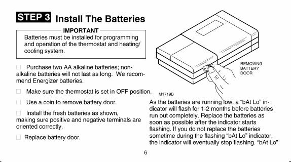
As the batteries are running low, a “bAt Lo” in-dicator will flash for 1-2 months before batteriesrun out completely. Replace the batteries assoon as possible after the indicator startsflashing. If you do not replace the batteriessometime during the flashing “bAt Lo” indicator,the indicator will eventually stop flashing. “bAt Lo”
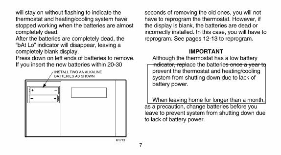
will stay on without flashing to indicate thethermostat and heating/cooling system havestopped working when the batteries are almostcompletely dead.After the batteries are completely dead, the“bAt Lo” indicator will disappear, leaving acompletely blank display.Press down on left ends of batteries to remove.If you insert the new batteries within 20-30
7
INSTALL TWO AA ALKALINE BATTERIES AS SHOWN
M1713
STEP 3
M1719B
REMOVINGBATTERYDOOR
Install The BatteriesIMPORTANT
Batteries must be installed for programmingand operation of the thermostat and heating/cooling system.
■■ Purchase two AA alkaline batteries; non-alkaline batteries will not last as long. We recom-mend Energizer batteries.
■■ Make sure the thermostat is set in OFF position.
■■ Use a coin to remove battery door.
■■ Install the fresh batteries as shown,making sure positive and negative terminals areoriented correctly.
■■ Replace battery door.
seconds of removing the old ones, you will nothave to reprogram the thermostat. However, ifthe display is blank, the batteries are dead orincorrectly installed. In this case, you will have toreprogram. See pages 12-13 to reprogram.
IMPORTANTAlthough the thermostat has a low batteryindicator, replace the batteries once a year toprevent the thermostat and heating/coolingsystem from shutting down due to lack ofbattery power.
When leaving home for longer than a month,as a precaution, change batteries before youleave to prevent system from shutting down dueto lack of battery power.
6
As the batteries are running low, a “bAt Lo” in-dicator will flash for 1-2 months before batteriesrun out completely. Replace the batteries assoon as possible after the indicator startsflashing. If you do not replace the batteriessometime during the flashing “bAt Lo” indicator,the indicator will eventually stop flashing. “bAt Lo”
will stay on without flashing to indicate thethermostat and heating/cooling system havestopped working when the batteries are almostcompletely dead.After the batteries are completely dead, the“bAt Lo” indicator will disappear, leaving acompletely blank display.Press down on left ends of batteries to remove.If you insert the new batteries within 20-30
7
INSTALL TWO AA ALKALINE BATTERIES AS SHOWN
M1713
STEP 3
M1719B
REMOVINGBATTERYDOOR
Install The BatteriesIMPORTANT
Batteries must be installed for programmingand operation of the thermostat and heating/cooling system.
■■ Purchase two AA alkaline batteries; non-alkaline batteries will not last as long. We recom-mend Energizer batteries.
■■ Make sure the thermostat is set in OFF position.
■■ Use a coin to remove battery door.
■■ Install the fresh batteries as shown,making sure positive and negative terminals areoriented correctly.
■■ Replace battery door.
seconds of removing the old ones, you will nothave to reprogram the thermostat. However, ifthe display is blank, the batteries are dead orincorrectly installed. In this case, you will have toreprogram. See pages 12-13 to reprogram.
IMPORTANTAlthough the thermostat has a low batteryindicator, replace the batteries once a year toprevent the thermostat and heating/coolingsystem from shutting down due to lack ofbattery power.
When leaving home for longer than a month,as a precaution, change batteries before youleave to prevent system from shutting down dueto lack of battery power.
9PROGRAMMING
STEP 4 Program The Thermostat
8
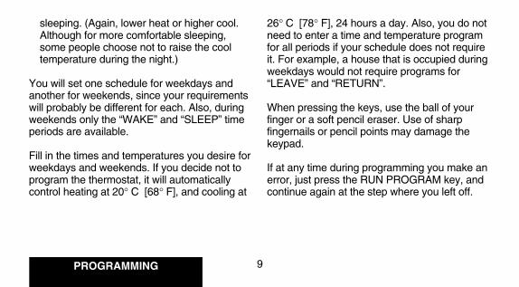
26° C [78° F], 24 hours a day. Also, you do notneed to enter a time and temperature programfor all periods if your schedule does not requireit. For example, a house that is occupied duringweekdays would not require programs for“LEAVE” and “RETURN”.
When pressing the keys, use the ball of yourfinger or a soft pencil eraser. Use of sharpfingernails or pencil points may damage thekeypad.
If at any time during programming you make anerror, just press the RUN PROGRAM key, andcontinue again at the step where you left off.
sleeping. (Again, lower heat or higher cool.Although for more comfortable sleeping,some people choose not to raise the cooltemperature during the night.)
You will set one schedule for weekdays andanother for weekends, since your requirementswill probably be different for each. Also, duringweekends only the “WAKE” and “SLEEP” timeperiods are available.
Fill in the times and temperatures you desire forweekdays and weekends. If you decide not toprogram the thermostat, it will automaticallycontrol heating at 20° C [68° F], and cooling at
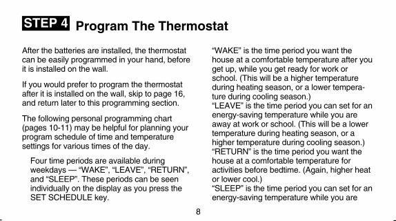
After the batteries are installed, the thermostatcan be easily programmed in your hand, beforeit is installed on the wall.
If you would prefer to program the thermostatafter it is installed on the wall, skip to page 16,and return later to this programming section.
The following personal programming chart(pages 10-11) may be helpful for planning yourprogram schedule of time and temperaturesettings for various times of the day.
Four time periods are available duringweekdays — “WAKE”, “LEAVE”, “RETURN”,and “SLEEP”. These periods can be seenindividually on the display as you press theSET SCHEDULE key.
“WAKE” is the time period you want thehouse at a comfortable temperature after youget up, while you get ready for work orschool. (This will be a higher temperatureduring heating season, or a lower tempera-ture during cooling season.)“LEAVE” is the time period you can set for anenergy-saving temperature while you areaway at work or school. (This will be a lowertemperature during heating season, or ahigher temperature during cooling season.)“RETURN” is the time period you want thehouse at a comfortable temperature foractivities before bedtime. (Again, higher heator lower cool.)“SLEEP” is the time period you can set for anenergy-saving temperature while you are
9PROGRAMMING
STEP 4 Program The Thermostat
8
26° C [78° F], 24 hours a day. Also, you do notneed to enter a time and temperature programfor all periods if your schedule does not requireit. For example, a house that is occupied duringweekdays would not require programs for“LEAVE” and “RETURN”.
When pressing the keys, use the ball of yourfinger or a soft pencil eraser. Use of sharpfingernails or pencil points may damage thekeypad.
If at any time during programming you make anerror, just press the RUN PROGRAM key, andcontinue again at the step where you left off.
sleeping. (Again, lower heat or higher cool.Although for more comfortable sleeping,some people choose not to raise the cooltemperature during the night.)
You will set one schedule for weekdays andanother for weekends, since your requirementswill probably be different for each. Also, duringweekends only the “WAKE” and “SLEEP” timeperiods are available.
Fill in the times and temperatures you desire forweekdays and weekends. If you decide not toprogram the thermostat, it will automaticallycontrol heating at 20° C [68° F], and cooling at
After the batteries are installed, the thermostatcan be easily programmed in your hand, beforeit is installed on the wall.
If you would prefer to program the thermostatafter it is installed on the wall, skip to page 16,and return later to this programming section.
The following personal programming chart(pages 10-11) may be helpful for planning yourprogram schedule of time and temperaturesettings for various times of the day.
Four time periods are available duringweekdays — “WAKE”, “LEAVE”, “RETURN”,and “SLEEP”. These periods can be seenindividually on the display as you press theSET SCHEDULE key.
“WAKE” is the time period you want thehouse at a comfortable temperature after youget up, while you get ready for work orschool. (This will be a higher temperatureduring heating season, or a lower tempera-ture during cooling season.)“LEAVE” is the time period you can set for anenergy-saving temperature while you areaway at work or school. (This will be a lowertemperature during heating season, or ahigher temperature during cooling season.)“RETURN” is the time period you want thehouse at a comfortable temperature foractivities before bedtime. (Again, higher heator lower cool.)“SLEEP” is the time period you can set for anenergy-saving temperature while you are
COOLING PROGRAM
Weekdays Start Time Cooling TemperatureWAKELEAVERETURNSLEEP
Weekends 1WAKESLEEP
1 If you decide not to enter weekend programs, the WAKE and SLEEP from the weekdayprogram will copy to the weekend schedule.
2 The temperatures cannot be set any higher than 31° C [88° F] or any lower than 7° C [45° F].
NOTE: If you decide not to program the thermostat, it will automatically control heating at20° C [68° F], and cooling at 26° C [78° F], 24 hours a day.
11PROGRAMMING
10
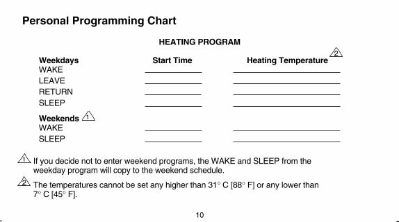
HEATING PROGRAM
Weekdays Start Time Heating TemperatureWAKELEAVERETURNSLEEP
Weekends 1WAKESLEEP
1 If you decide not to enter weekend programs, the WAKE and SLEEP from theweekday program will copy to the weekend schedule.
2 The temperatures cannot be set any higher than 31° C [88° F] or any lower than7° C [45° F].
Personal Programming Chart
2
2

COOLING PROGRAM
Weekdays Start Time Cooling TemperatureWAKELEAVERETURNSLEEP
Weekends 1WAKESLEEP
1 If you decide not to enter weekend programs, the WAKE and SLEEP from the weekdayprogram will copy to the weekend schedule.
2 The temperatures cannot be set any higher than 31° C [88° F] or any lower than 7° C [45° F].
NOTE: If you decide not to program the thermostat, it will automatically control heating at20° C [68° F], and cooling at 26° C [78° F], 24 hours a day.
11PROGRAMMING
10
HEATING PROGRAM
Weekdays Start Time Heating TemperatureWAKELEAVERETURNSLEEP
Weekends 1WAKESLEEP
1 If you decide not to enter weekend programs, the WAKE and SLEEP from theweekday program will copy to the weekend schedule.
2 The temperatures cannot be set any higher than 31° C [88° F] or any lower than7° C [45° F].
Personal Programming Chart
2
2

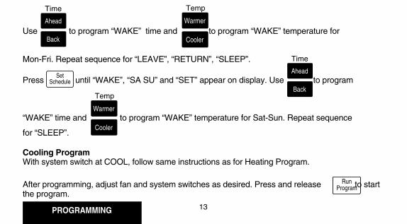
Heating ProgramWith system switch at HEAT, press and release once. “WAKE”, Mon-Fri and “SET”
appear on display.
Use to program “WAKE” time and to program “WAKE” temperature for
Mon-Fri. Repeat sequence for “LEAVE”, “RETURN”, “SLEEP”.
PROGRAMMING
This guide can be used for programming your new thermostat.
NOTE: Batteries are required for operation and programming. When inserting batteries, setsystem switch to OFF. Remove battery door (on thermostat left side) using a coin at the bottom.Follow instructions on pages 6-7.
Set Current Time/Day
12
Warmer
Cooler
13
RunProgram
Ahead
Back
Time Temp
To set time, press and release once, until current time shows; to set day,
press and release again, until current day shows; then press .
SetClock/Day
Ahead
Back
Time
SetClock/Day
Ahead
Back
Time
RunProgram
SetSchedule
Cooling ProgramWith system switch at COOL, follow same instructions as for Heating Program.
After programming, adjust fan and system switches as desired. Press and release to startthe program.
Press until “WAKE”, “SA SU” and “SET” appear on display. Use to program
“WAKE” time and to program “WAKE” temperature for Sat-Sun. Repeat sequence
for “SLEEP”.
SetSchedule
Warmer
Cooler
Temp
Ahead
Back
Time

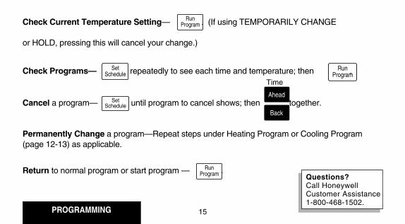
Check Current Temperature Setting— . (If using TEMPORARILY CHANGE
or HOLD, pressing this will cancel your change.)
Check Programs— repeatedly to see each time and temperature; then .
Cancel a program— until program to cancel shows; then together.
Permanently Change a program—Repeat steps under Heating Program or Cooling Program(page 12-13) as applicable.
Return to normal program or start program — .
Temporarily Change temperature for current period only— ;
will cancel itself at next scheduled change, or to cancel sooner press .
Hold a temperature indefinitely— , ; to cancel press .
PROGRAMMING
A quick guide for operating or making changes follows:
NOTE: System switch must be set to Heat or Cool to perform the following.
14
SetSchedule
RunProgram
SetSchedule
RunProgram
Ahead
Back
Time
HoldTemp
Warmer
Cooler
Temp
Warmer
Cooler
Temp
RunProgram
RunProgram
RunProgram
15
Questions?Call HoneywellCustomer Assistance1-800-468-1502.
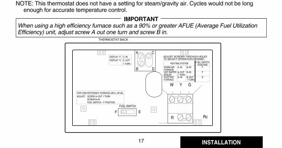
If on-length screws A,B are adjusted For longer on-length, readjust screws A,Bto match this system: to match this system:
electric furnace warm air furnacewarm air furnace hot water boiler
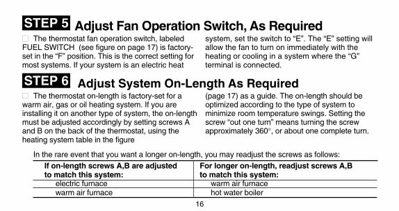
NOTE: This thermostat does not have a setting for steam/gravity air. Cycles would not be longenough for accurate temperature control.
IMPORTANTWhen using a high efficiency furnace such as a 90% or greater AFUE (Average Fuel UtilizationEfficiency) unit, adjust screw A out one turn and screw B in.
INSTALLATION
16
17
Adjust System On-Length As Required
STEP 5
STEP 6
Adjust Fan Operation Switch, As Required■■ The thermostat fan operation switch, labeledFUEL SWITCH (see figure on page 17) is factory-set in the “F” position. This is the correct setting formost systems. If your system is an electric heat
system, set the switch to “E”. The “E” setting willallow the fan to turn on immediately with theheating or cooling in a system where the “G”terminal is connected.
■■ The thermostat on-length is factory-set for awarm air, gas or oil heating system. If you areinstalling it on another type of system, the on-lengthmust be adjusted accordingly by setting screws Aand B on the back of the thermostat, using theheating system table in the figure
(page 17) as a guide. The on-length should beoptimized according to the type of system tominimize room temperature swings. Setting thescrew “out one turn” means turning the screwapproximately 360°, or about one complete turn.
In the rare event that you want a longer on-length, you may readjust the screws as follows:
R Rc
W Y G
B D
A C
THERMOSTAT BACK
DISPLAY °FDISPLAY °C
C–INC–OUT1 TURN
FOR HIGH EFFICIENCY FURNACE (90%+ AFUE)ADJUST: SCREW A–OUT 1 TURN
SCREW B–INFUEL SWITCH – F POSITION
F E
FUEL SWITCH
WARM AIRFURNACEHOT WATERBOILERELECTRIC FURNACE
A–IN
A–OUT1 TURNA–IN
ADJUST SCREWS THROUGH HOLESTO SELECT OPERATION DESIRED
B–IN
B–IN
B–OUT1 TURN
FUEL SWITCHPOSITION
F
F
E
HEATING SYSTEM
If on-length screws A,B are adjusted For longer on-length, readjust screws A,Bto match this system: to match this system:
electric furnace warm air furnacewarm air furnace hot water boiler
NOTE: This thermostat does not have a setting for steam/gravity air. Cycles would not be longenough for accurate temperature control.
IMPORTANTWhen using a high efficiency furnace such as a 90% or greater AFUE (Average Fuel UtilizationEfficiency) unit, adjust screw A out one turn and screw B in.
INSTALLATION
16
17
Adjust System On-Length As Required
STEP 5
STEP 6
Adjust Fan Operation Switch, As Required■■ The thermostat fan operation switch, labeledFUEL SWITCH (see figure on page 17) is factory-set in the “F” position. This is the correct setting formost systems. If your system is an electric heat
system, set the switch to “E”. The “E” setting willallow the fan to turn on immediately with theheating or cooling in a system where the “G”terminal is connected.
■■ The thermostat on-length is factory-set for awarm air, gas or oil heating system. If you areinstalling it on another type of system, the on-lengthmust be adjusted accordingly by setting screws Aand B on the back of the thermostat, using theheating system table in the figure
(page 17) as a guide. The on-length should beoptimized according to the type of system tominimize room temperature swings. Setting thescrew “out one turn” means turning the screwapproximately 360°, or about one complete turn.
In the rare event that you want a longer on-length, you may readjust the screws as follows:
R Rc
W Y G
B D
A C
THERMOSTAT BACK
DISPLAY °FDISPLAY °C
C–INC–OUT1 TURN
FOR HIGH EFFICIENCY FURNACE (90%+ AFUE)ADJUST: SCREW A–OUT 1 TURN
SCREW B–INFUEL SWITCH – F POSITION
F E
FUEL SWITCH
WARM AIRFURNACEHOT WATERBOILERELECTRIC FURNACE
A–IN
A–OUT1 TURNA–IN
ADJUST SCREWS THROUGH HOLESTO SELECT OPERATION DESIRED
B–IN
B–IN
B–OUT1 TURN
FUEL SWITCHPOSITION
F
F
E
HEATING SYSTEM
Mount Thermostat Mounting Plate
19
18
INSTALLATION
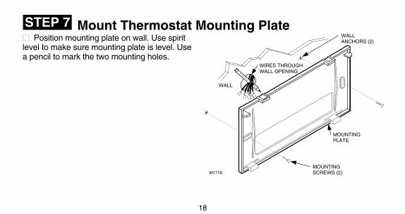
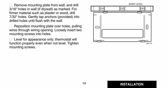
STEP 7■■ Position mounting plate on wall. Use spiritlevel to make sure mounting plate is level. Usea pencil to mark the two mounting holes.
■■ Remove mounting plate from wall, and drill3/16" holes in wall (if drywall) as marked. Forfirmer material such as plaster or wood, drill7/32" holes. Gently tap anchors (provided) intodrilled holes until flush with the wall.
■■ Reposition mounting plate over holes, pullingwires through wiring opening. Loosely insert twomounting screws into holes.
■■ Level for appearance only; thermostat willfunction properly even when not level. Tightenmounting screws.
WALL
WIRES THROUGHWALL OPENING
WALLANCHORS (2)
MOUNTINGPLATE
MOUNTINGSCREWS (2)M1718
SPIRIT LEVEL
M1714
Mount Thermostat Mounting Plate
19
18
INSTALLATION
STEP 7■■ Position mounting plate on wall. Use spiritlevel to make sure mounting plate is level. Usea pencil to mark the two mounting holes.
■■ Remove mounting plate from wall, and drill3/16" holes in wall (if drywall) as marked. Forfirmer material such as plaster or wood, drill7/32" holes. Gently tap anchors (provided) intodrilled holes until flush with the wall.
■■ Reposition mounting plate over holes, pullingwires through wiring opening. Loosely insert twomounting screws into holes.
■■ Level for appearance only; thermostat willfunction properly even when not level. Tightenmounting screws.
WALL
WIRES THROUGHWALL OPENING
WALLANCHORS (2)
MOUNTINGPLATE
MOUNTINGSCREWS (2)M1718
SPIRIT LEVEL
M1714
INSTALLATION
20
21
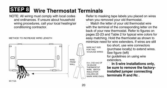
STEP 8 Wire Thermostat TerminalsNOTE: All wiring must comply with local codes
and ordinances. If unsure about householdwiring procedures, call your local heating/airconditioning contractor.
Refer to masking tape labels you placed on wireswhen you removed your old thermostat.■■ Match the letter of your old thermostat wirewith the terminal of the corresponding letter on theback of your new thermostat. Refer to figures onpages 22-23 and Table 2 for typical wire colors foreasy matching. Hold the thermostat as shown tominimize need for wire extenders. If wires are still
too short, use wire connectors(purchase locally) to extend wires.See figure (left)for guidelines on using wireextenders.■■ In 5-wire installations only,be sure to remove the factory-installed jumper connectingterminals R and Rc .
M1715A
WIRE NUT SIZE FOR TWO 18-GAUGE WIRES
WIRE FROMWALL
6-in. [152 mm] OF 18-GAUGE THERMOSTAT WIRE. MATCHINSULATION COLORS OR MARK WIRE ENDS.
METHOD TO INCREASE WIRE LENGTH
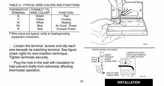
TABLE 2—TYPICAL WIRE COLORS AND FUNCTIONS.
THERMOSTAT CONNECT TOTERMINAL WIRE COLORa FUNCTION
G Green FanY Yellow CoolingW White HeatingRc Blue Air Cond. PowerR Red Furnace Power
a Wire colors are typical; verify at heating/coolingequipment connection.
■■ Loosen the terminal screws and slip eachwire beneath its matching terminal. See figure(lower right) for wire insertion technique.Tighten terminals securely.
■■ Plug the hole in the wall with insulation tohelp prevent drafts from adversely affectingthermostat operation.
M3002
M1712A
JUMPER (FACTORY-INSTALLED) REMOVE IF 5-WIRE SYSTEM
INSERTSTRAIGHT UNDER SCREW HEAD
5/16 in. [8 mm]STRIP
END OF WIRE VISIBLE HERE
RRc
WYG
PROPER WIRING TECHNIQUE
INSTALLATION
20
21
STEP 8 Wire Thermostat TerminalsNOTE: All wiring must comply with local codes
and ordinances. If unsure about householdwiring procedures, call your local heating/airconditioning contractor.
Refer to masking tape labels you placed on wireswhen you removed your old thermostat.■■ Match the letter of your old thermostat wirewith the terminal of the corresponding letter on theback of your new thermostat. Refer to figures onpages 22-23 and Table 2 for typical wire colors foreasy matching. Hold the thermostat as shown tominimize need for wire extenders. If wires are still
too short, use wire connectors(purchase locally) to extend wires.See figure (left)for guidelines on using wireextenders.■■ In 5-wire installations only,be sure to remove the factory-installed jumper connectingterminals R and Rc .
M1715A
WIRE NUT SIZE FOR TWO 18-GAUGE WIRES
WIRE FROMWALL
6-in. [152 mm] OF 18-GAUGE THERMOSTAT WIRE. MATCHINSULATION COLORS OR MARK WIRE ENDS.
METHOD TO INCREASE WIRE LENGTH
TABLE 2—TYPICAL WIRE COLORS AND FUNCTIONS.
THERMOSTAT CONNECT TOTERMINAL WIRE COLORa FUNCTION
G Green FanY Yellow CoolingW White HeatingRc Blue Air Cond. PowerR Red Furnace Power
a Wire colors are typical; verify at heating/coolingequipment connection.
■■ Loosen the terminal screws and slip eachwire beneath its matching terminal. See figure(lower right) for wire insertion technique.Tighten terminals securely.
■■ Plug the hole in the wall with insulation tohelp prevent drafts from adversely affectingthermostat operation.
M3002
M1712A
JUMPER (FACTORY-INSTALLED) REMOVE IF 5-WIRE SYSTEM
INSERTSTRAIGHT UNDER SCREW HEAD
5/16 in. [8 mm]STRIP
END OF WIRE VISIBLE HERE
RRc
WYG
PROPER WIRING TECHNIQUE

22
23 INSTALLATION
R Rc
W Y G
B D
A C
2-WIRE HEAT-ONLY (JUMPER INTACT)
M1709A
L1(HOT)
L2
POWER SUPPLY. PROVIDE DISCONNECT MEANS ANDOVERLOAD PROTECTION AS REQUIRED.
1
1
HEATINGRELAY ORVALVE COIL
JUMPER
R Rc
W Y G
B D
A C
4-WIRE HEAT/COOL (JUMPER INTACT)
L1(HOT)
L2
POWER SUPPLY. PROVIDE DISCONNECT MEANS ANDOVERLOAD PROTECTION AS REQUIRED.
1
JUMPERHEATINGRELAY ORVALVE COIL
M1710A
COOLINGCONTACTORCOIL
FANRELAY
R Rc
W Y G
B D
A C
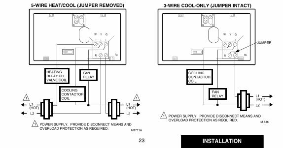
5-WIRE HEAT/COOL (JUMPER REMOVED)
L1(HOT)
L2
POWER SUPPLY. PROVIDE DISCONNECT MEANS ANDOVERLOAD PROTECTION AS REQUIRED.
1
M1711A
L1(HOT)
L2
COOLINGCONTACTORCOIL
FANRELAY
HEATINGRELAY ORVALVE COIL
1 1
R Rc
W Y G
B D
A C
3-WIRE COOL-ONLY (JUMPER INTACT)
L1(HOT)
L2
POWER SUPPLY. PROVIDE DISCONNECT MEANS ANDOVERLOAD PROTECTION AS REQUIRED.
1
JUMPER
M 848
COOLINGCONTACTORCOIL
FANRELAY
22
23 INSTALLATION
R Rc
W Y G
B D
A C
2-WIRE HEAT-ONLY (JUMPER INTACT)
M1709A
L1(HOT)
L2
POWER SUPPLY. PROVIDE DISCONNECT MEANS ANDOVERLOAD PROTECTION AS REQUIRED.
1
1
HEATINGRELAY ORVALVE COIL
JUMPER
R Rc
W Y G
B D
A C
4-WIRE HEAT/COOL (JUMPER INTACT)
L1(HOT)
L2
POWER SUPPLY. PROVIDE DISCONNECT MEANS ANDOVERLOAD PROTECTION AS REQUIRED.
1
JUMPERHEATINGRELAY ORVALVE COIL
M1710A
COOLINGCONTACTORCOIL
FANRELAY
R Rc
W Y G
B D
A C
5-WIRE HEAT/COOL (JUMPER REMOVED)
L1(HOT)
L2
POWER SUPPLY. PROVIDE DISCONNECT MEANS ANDOVERLOAD PROTECTION AS REQUIRED.
1
M1711A
L1(HOT)
L2
COOLINGCONTACTORCOIL
FANRELAY
HEATINGRELAY ORVALVE COIL
1 1
R Rc
W Y G
B D
A C
3-WIRE COOL-ONLY (JUMPER INTACT)
L1(HOT)
L2
POWER SUPPLY. PROVIDE DISCONNECT MEANS ANDOVERLOAD PROTECTION AS REQUIRED.
1
JUMPER
M 848
COOLINGCONTACTORCOIL
FANRELAY
Check Thermostat Operation After Programming And Installing
M 879
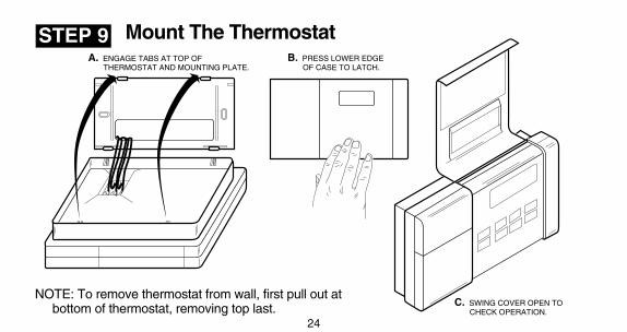
B. PRESS LOWER EDGE OF CASE TO LATCH.
C. SWING COVER OPEN TO CHECK OPERATION.
A. ENGAGE TABS AT TOP OF THERMOSTAT AND MOUNTING PLATE.
24
25
HeatCool Off
Auto On
Mount The Thermostat
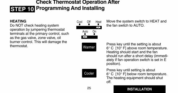
HEATINGDo NOT check heating systemoperation by jumpering thermostatterminals at the primary control, suchas the gas valve, zone valve, oilburner control. This will damage thethermostat.
INSTALLATION
STEP 9
STEP 10
Move the system switch to HEAT andthe fan switch to AUTO.
Press key until the setting is about6° C [10° F] above room temperature.Heating should start and the fanshould run after a short delay (immedi-ately if fan operation switch is set in Eposition).
Press key until setting is about6° C [10° F] below room temperature.The heating equipment should shutoff.
Warmer
Cooler
NOTE: To remove thermostat from wall, first pull out atbottom of thermostat, removing top last.
Check Thermostat Operation After Programming And Installing
M 879
B. PRESS LOWER EDGE OF CASE TO LATCH.
C. SWING COVER OPEN TO CHECK OPERATION.
A. ENGAGE TABS AT TOP OF THERMOSTAT AND MOUNTING PLATE.
24
25
HeatCool Off
Auto On
Mount The Thermostat
HEATINGDo NOT check heating systemoperation by jumpering thermostatterminals at the primary control, suchas the gas valve, zone valve, oilburner control. This will damage thethermostat.
INSTALLATION
STEP 9
STEP 10
Move the system switch to HEAT andthe fan switch to AUTO.
Press key until the setting is about6° C [10° F] above room temperature.Heating should start and the fanshould run after a short delay (immedi-ately if fan operation switch is set in Eposition).
Press key until setting is about6° C [10° F] below room temperature.The heating equipment should shutoff.
Warmer
Cooler
NOTE: To remove thermostat from wall, first pull out atbottom of thermostat, removing top last.

Cooler
26
27
HeatCool Off
Auto On
Move the system switch to COOLand the fan switch to AUTO.
Press key until setting is about6° C [10° F] below room tempera-ture. The cooling equipment and fanshould start.
Press key until the setting is about6° C [10° F] above room tempera-ture. The cooling equipment and fanshould stop.
Move the system switch to OFF,with the fan switch still at AUTO.The system and fan should be off.
COOL: The thermostat controls yourHeatCool Off
HeatCool Off
HeatCool Off
INSTALLATION
Auto On
HeatCool Off
Auto On
Auto On
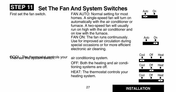
STEP 11First set the fan switch. Set The Fan And System Switches
FAN AUTO: Normal setting for mosthomes. A single-speed fan will turn onautomatically with the air conditioner orfurnace. A two-speed fan will usuallyrun on high with the air conditioner andon low with the furnace.FAN ON: The fan runs continuously.Use for improved air circulation duringspecial occasions or for more efficientelectronic air cleaning.
air conditioning system.OFF: Both the heating and air condi-tioning systems are off.HEAT: The thermostat controls yourheating system.
Then set the system switch.
Warmer
COOLINGTo avoid possible compressordamage, do not operate the coolingsystem when outside temperatureis below 10° C [50° F]. See com-pressor manu-facturer’s instructionsfor further information.
NOTE: When cooling setting ischanged, thermostat may delayup to five minutes before turningon the air conditioner. This delayprotects the compressor.
Cooler
26
27
HeatCool Off
Auto On
Move the system switch to COOLand the fan switch to AUTO.
Press key until setting is about6° C [10° F] below room tempera-ture. The cooling equipment and fanshould start.
Press key until the setting is about6° C [10° F] above room tempera-ture. The cooling equipment and fanshould stop.
Move the system switch to OFF,with the fan switch still at AUTO.The system and fan should be off.
COOL: The thermostat controls yourHeatCool Off
HeatCool Off
HeatCool Off
INSTALLATION
Auto On
HeatCool Off
Auto On
Auto On
STEP 11First set the fan switch. Set The Fan And System Switches
FAN AUTO: Normal setting for mosthomes. A single-speed fan will turn onautomatically with the air conditioner orfurnace. A two-speed fan will usuallyrun on high with the air conditioner andon low with the furnace.FAN ON: The fan runs continuously.Use for improved air circulation duringspecial occasions or for more efficientelectronic air cleaning.
air conditioning system.OFF: Both the heating and air condi-tioning systems are off.HEAT: The thermostat controls yourheating system.
Then set the system switch.
Warmer
COOLINGTo avoid possible compressordamage, do not operate the coolingsystem when outside temperatureis below 10° C [50° F]. See com-pressor manu-facturer’s instructionsfor further information.
NOTE: When cooling setting ischanged, thermostat may delayup to five minutes before turningon the air conditioner. This delayprotects the compressor.
29
28
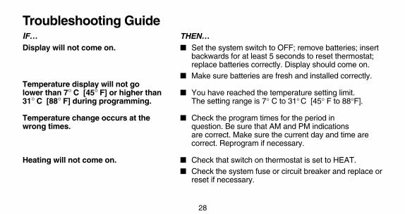
Troubleshooting GuideIF… THEN…Display will not come on. ■ Set the system switch to OFF; remove batteries; insert
backwards for at least 5 seconds to reset thermostat;replace batteries correctly. Display should come on.
■ Make sure batteries are fresh and installed correctly.Temperature display will not golower than 7° C [45° F] or higher than ■ You have reached the temperature setting limit.31° C [88° F] during programming. The setting range is 7° C to 31°C [45° F to 88°F].
Temperature change occurs at the ■ Check the program times for the period inwrong times. question. Be sure that AM and PM indications
are correct. Make sure the current day and time arecorrect. Reprogram if necessary.
Heating will not come on. ■ Check that switch on thermostat is set to HEAT.■ Check the system fuse or circuit breaker and replace or
reset if necessary.
■ If display is blank or says "bAt Lo," install freshbatteries.
■ If temperature setting is higher than current tempera-ture, and SYSTEM ON indicator is lit, contact Honey-well Customer Assistance at 1-800-468-1502.
Cooling will not come on. ■ Check that switch on thermostat is set to COOL.■ Check the system fuse or circuit breaker and replace or
reset if necessary.■ If display is blank or says "bAt Lo," install fresh
batteries.■ The thermostat has a built-in time delay on cooling.
Allow 5 to 10 minutes after changing the setting beforethe air conditioner starts.
■ If temperature setting is lower than current tempera-ture, and SYSTEM ON indicator is lit, move systemswitch from COOL to OFF for 10 minutes. After 10minutes, return switch to COOL position. If air

29
28
Troubleshooting GuideIF… THEN…Display will not come on. ■ Set the system switch to OFF; remove batteries; insert
backwards for at least 5 seconds to reset thermostat;replace batteries correctly. Display should come on.
■ Make sure batteries are fresh and installed correctly.Temperature display will not golower than 7° C [45° F] or higher than ■ You have reached the temperature setting limit.31° C [88° F] during programming. The setting range is 7° C to 31°C [45° F to 88°F].
Temperature change occurs at the ■ Check the program times for the period inwrong times. question. Be sure that AM and PM indications
are correct. Make sure the current day and time arecorrect. Reprogram if necessary.
Heating will not come on. ■ Check that switch on thermostat is set to HEAT.■ Check the system fuse or circuit breaker and replace or
reset if necessary.
■ If display is blank or says "bAt Lo," install freshbatteries.
■ If temperature setting is higher than current tempera-ture, and SYSTEM ON indicator is lit, contact Honey-well Customer Assistance at 1-800-468-1502.
Cooling will not come on. ■ Check that switch on thermostat is set to COOL.■ Check the system fuse or circuit breaker and replace or
reset if necessary.■ If display is blank or says "bAt Lo," install fresh
batteries.■ The thermostat has a built-in time delay on cooling.
Allow 5 to 10 minutes after changing the setting beforethe air conditioner starts.
■ If temperature setting is lower than current tempera-ture, and SYSTEM ON indicator is lit, move systemswitch from COOL to OFF for 10 minutes. After 10minutes, return switch to COOL position. If air

31
30
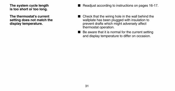
The system cycle length ■ Readjust according to instructions on pages 16-17.is too short or too long.
The thermostat's current ■ Check that the wiring hole in the wall behind thesetting does not match the wallplate has been plugged with insulation todisplay temperature. prevent drafts which might adversely affect
thermostat operation.■ Be aware that it is normal for the current setting
and display temperature to differ on occasion.
Cooling will not come on. (Cont.) conditioner comes on, compressor may have reachedits high limit temperature protection and shut down. If airconditioner does not come on after the 10 minutes andthe SYSTEM ON indicator is lit, contact HoneywellConsumer Services at 1-800-468-1502.
■ If 2- or 4-wire installation, verify that R-Rc jumper isinstalled.
The house is too warm or too cool. ■ Press RUN PROGRAM key to check the currenttemperature setting.
■ If desired, change the temperature setting. Seepage 14.
SYSTEM ON indicator is lit, but no ■ Allow time for the furnace to heat up and the fan toheat is coming from the registers. come on before checking for heat at the register.
Check to make sure system on-length is setcorrectly according to page 16.)
Furnace or air conditioner cycles ■ Check system setting on back of thermostat.too frequently.
31
30
The system cycle length ■ Readjust according to instructions on pages 16-17.is too short or too long.
The thermostat's current ■ Check that the wiring hole in the wall behind thesetting does not match the wallplate has been plugged with insulation todisplay temperature. prevent drafts which might adversely affect
thermostat operation.■ Be aware that it is normal for the current setting
and display temperature to differ on occasion.
Cooling will not come on. (Cont.) conditioner comes on, compressor may have reachedits high limit temperature protection and shut down. If airconditioner does not come on after the 10 minutes andthe SYSTEM ON indicator is lit, contact HoneywellConsumer Services at 1-800-468-1502.
■ If 2- or 4-wire installation, verify that R-Rc jumper isinstalled.
The house is too warm or too cool. ■ Press RUN PROGRAM key to check the currenttemperature setting.
■ If desired, change the temperature setting. Seepage 14.
SYSTEM ON indicator is lit, but no ■ Allow time for the furnace to heat up and the fan toheat is coming from the registers. come on before checking for heat at the register.
Check to make sure system on-length is setcorrectly according to page 16.)
Furnace or air conditioner cycles ■ Check system setting on back of thermostat.too frequently.

Limited One-Year WarrantyHoneywell warrants this product, excluding battery, to be free from defects in the workmanship or materials, under normal use and service, for
a period of one (1) year from the date of purchase by the consumer. If, at any time during the warranty period, the product is defective or malfunctions,Honeywell shall repair or replace it (at Honeywell’s option) within a reasonable period of time.
If the product is defective,(i) return it, with a bill of sale or other dated proof of purchase, to the retailer from which you purchased it, or(ii) package it carefully, along with proof of purchase (including date of purchase) and a short description of the
malfunction, and mail it, postage prepaid, to the following address:Honeywell Inc. in Canada: Honeywell Limited/Honeywell LimitéeReturn Goods Department Product Services ON15-FFE1050 Berkshire Lane 740 Ellesmere RoadPlymouth, MN 55441-4437 Scarborough, Ontario M1P 2V9
This warranty does not cover removal or reinstallation costs. This warranty shall not apply if it is shown by Honeywell that the defect or malfunctionwas caused by damage which occurred while the product was in the possession of a consumer.
Honeywell’s sole responsibility shall be to repair or replace the product within the terms stated above. HONEYWELL SHALL NOT BE LIABLE FORANY LOSS OR DAMAGE OF ANY KIND, INCLUDING ANY INCIDENTAL OR CONSEQUENTIAL DAMAGES RESULTING, DIRECTLY ORINDIRECTLY, FROM ANY BREACH OF ANY WARRANTY, EXPRESS OR IMPLIED, OR ANY OTHER FAILURE OF THIS PRODUCT. Somestates do not allow the exclusion or limitation of incidental or consequential damages, so this limitation may not apply to you.
THIS WARRANTY IS THE ONLY EXPRESS WARRANTY HONEYWELL MAKES ON THIS PRODUCT. THE DURATION OF ANY IMPLIEDWARRANTIES, INCLUDING THE WARRANTIES OF MERCHANTABILITY AND FITNESS FOR A PARTICULAR PURPOSE, IS HEREBYLIMITED TO THE ONE YEAR DURATION OF THIS WARRANTY. Some states do not allow limitations on how long an implied warranty lasts,so the above limitation may not apply to you.
This warranty gives you specific legal rights, and you may have other rights which vary from state to state.
If you have any questions concerning this warranty, please write our Customer Assistance Center, Honeywell Inc., P.O. Box 524, MN27-2164,Minneapolis, MN 55440-0524 or call 1-800-468-1502, Monday-Friday, 7:00 a.m. to 5:30 p.m., Central time. In Canada, write Retail Products ON15-02H, Honeywell Limited/Honeywell Limitée, 740 Ellesmere Road, Scarborough, Ontario M1P 2V9.
33
Toll-free Customer AssistanceFor all questions concerning this thermostat, please read and follow the instructions. If additional
assistance is needed, call Honeywell Customer Assistance toll-free at 1-800-468-1502, Monday-Friday, 7:00 a.m. - 5:30 p.m. Central time.
Before you call, please have the following information available—thermostat model number anddate code, kind of heating/cooling system (i.e., hot water, warm air, oil, gas, etc.), number of wiresconnected to the thermostat.
NOTICEThis equipment is a Class B digital apparatus, which complies with Canadian Radio Interference Regula-tions, CRC c.1374.
32
PROGRAMMABLETHERMOSTAT
Honeywell
Thermostat patents pending.
Printed in Mexico • J.H. • ©Honeywell Inc. 1992
Weekday/WeekendProgrammable Heat and/or CoolThermostat and Mounting Plate
Model T8132
MagicStat/T8132
BY HONEYWELL
Rev. 9-92 • Form Number 69-0740B—1
PROGRAMMING AND INSTALLATIONINSTRUCTIONS
30%
28%
26%
24%
22%
20%
18%
16%
14%
12%
8%
6%
2%
10%
4%
MinneapolisSt. PaulMontrealOttawaToronto
BuffaloClevelandMilwaukee
EdmontonReginaWinnipeg
CalgaryMonctonNorth BayQuebecSt. John's
Halifax Vancouver DenverDes Moines OmahaSalt Lake City
BostonChicagoDetroitPittsburghIndianapolis
CincinnatiKansas CitySt. LouisColumbus
New YorkPhiladelphiaSeattle
LouisvillePortlandWash., D C
San Francisco
DallasAtlanta
Los Angeles
App
roxi
mat
e pe
rcen
tage
of e
nerg
y co
st s
avin
gs
Savings for Once-A-Day10°F (5°C) decrease
Savings for Twice-A-Day10°F (5°C) decrease*
Savings for 5°F (3°)summer increase
TYPICAL ENERGY SAVINGS FOR REPRESENTATIVE CITIES IN THE U.S. AND CANADA
*Based on 10°F (5°C) decrease—(5°F (3°C) decrease gives approximately 55 percent of these savings). M2416A
San Diego

THERMOSTATPROGRAMMABLEDE HONEYWELL
MagicStatmd/T8132
Thermostat programmable et plaque de montagepour systèmes de chauffage et (ou) de
refroidissement avec programmation pour lasemaine et la fin de semaine
Modèle T8132
9-92 • Publication no 69-0740B—1
MANUEL DE PROGRAMMATIONET D’INSTALLATION
Brevet en instance
Imprimé à Mexique • J.H. • Honeywell Inc., 1992
30%
28%
26%
24%
22%
20%
18%
16%
14%
12%
8%
6%
2%
10%
4%
MinneapolisSt. PaulMontréal OttawaToronto
BuffaloClevelandMilwaukee
EdmontonReginaWinnipeg
CalgaryMonctonNorth BayQuébecSt-Jean
Halifax Vancouver DenverDes Moines OmahaSalt Lake City
BostonChicagoDetroitPittsburghIndianapolis
CincinnatiKansas CitySt-Louis Columbus
New YorkPhiladelphieSeattle
LouisvillePortlandWash. D.C.
San Francisco
DallasAtlanta
Los AngelesPO
UR
CE
NT
AG
E M
OY
EN
DE
S É
CO
NO
MIE
S D
'ÉN
ER
GIE
Économies pour une diminution de 5 °C (10 °F), une fois par jour
Économies pour une diminution de 5 °C (10 °F), deux fois par jour *
Économies pour une augmentation de 3 °C (5 °F)
ÉCONOMIES D'ÉNERGIE TYPES DANS CERTAINES VILLES DES ÉTAT-UNIS ET DU CANADA
* Une baisse de 5 °C (10 °F)—(une baisse de 3 °C (5 °F) donne environ 55 % de ces économies d'énergie). MF2416A
San Diego
1
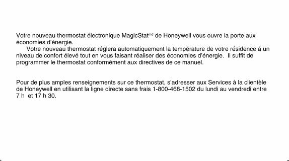
Votre nouveau thermostat électronique MagicStatmd de Honeywell vous ouvre la porte auxéconomies d’énergie.
Votre nouveau thermostat réglera automatiquement la température de votre résidence à unniveau de confort élevé tout en vous faisant réaliser des économies d’énergie. Il suffit deprogrammer le thermostat conformément aux directives de ce manuel.
Pour de plus amples renseignements sur ce thermostat, s’adresser aux Services à la clientèlede Honeywell en utilisant la ligne directe sans frais 1-800-468-1502 du lundi au vendredi entre7 h et 17 h 30.
TABLE DES MATIÈRES
ÉTAPE 1 Avant l’installation ...................................................................................................2ÉTAPE 2 Retrait de l’ancien thermostat ................................................................................4ÉTAPE 3 Installation des piles ................................................................................................ 6ÉTAPE 4 Programmation du thermostat ............................................................................... 8ÉTAPE 5 Réglage du commutateur du ventilateur, au besoin .......................................... 16ÉTAPE 6 Réglage des cycles de fonctionnement au besoin ............................................. 16ÉTAPE 7 Installation de la plaque de montage ................................................................... 18ÉTAPE 8 Raccordement des bornes du thermostat ........................................................... 20ÉTAPE 9 Installation du thermostat ..................................................................................... 24ÉTAPE 10 Vérification de la programmation et de l’installation ......................................... 25ÉTAPE 11 Réglage des commutateurs du ventilateur et du système ............................... 27Guide de dépannage ................................................................................................................. 28Garantie restreinte pour un an ................................................................................................32

1
Votre nouveau thermostat électronique MagicStatmd de Honeywell vous ouvre la porte auxéconomies d’énergie.
Votre nouveau thermostat réglera automatiquement la température de votre résidence à unniveau de confort élevé tout en vous faisant réaliser des économies d’énergie. Il suffit deprogrammer le thermostat conformément aux directives de ce manuel.
Pour de plus amples renseignements sur ce thermostat, s’adresser aux Services à la clientèlede Honeywell en utilisant la ligne directe sans frais 1-800-468-1502 du lundi au vendredi entre7 h et 17 h 30.
TABLE DES MATIÈRES
ÉTAPE 1 Avant l’installation ...................................................................................................2ÉTAPE 2 Retrait de l’ancien thermostat ................................................................................4ÉTAPE 3 Installation des piles ................................................................................................ 6ÉTAPE 4 Programmation du thermostat ............................................................................... 8ÉTAPE 5 Réglage du commutateur du ventilateur, au besoin .......................................... 16ÉTAPE 6 Réglage des cycles de fonctionnement au besoin ............................................. 16ÉTAPE 7 Installation de la plaque de montage ................................................................... 18ÉTAPE 8 Raccordement des bornes du thermostat ........................................................... 20ÉTAPE 9 Installation du thermostat ..................................................................................... 24ÉTAPE 10 Vérification de la programmation et de l’installation ......................................... 25ÉTAPE 11 Réglage des commutateurs du ventilateur et du système ............................... 27Guide de dépannage ................................................................................................................. 28Garantie restreinte pour un an ................................................................................................32
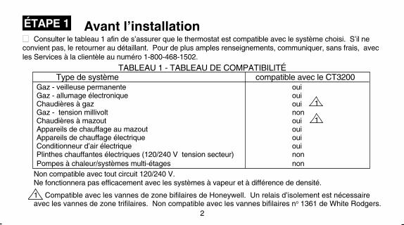
1 Compatible avec les vannes de zone bifilaires de Honeywell. Un relais d’isolement est nécessaireavec les vannes de zone trifilaires. Non compatible avec les vannes bifilaires no 1361 de White Rodgers.
Avant l’installation■■ Consulter le tableau 1 afin de s’assurer que le thermostat est compatible avec le système choisi. S’il neconvient pas, le retourner au détaillant. Pour de plus amples renseignements, communiquer, sans frais, avecles Services à la clientèle au numéro 1-800-468-1502.
TABLEAU 1 - TABLEAU DE COMPATIBILITÉType de système compatible avec le CT3200
Gaz - veilleuse permanente ouiGaz - allumage électronique ouiChaudières à gaz oui 1Gaz - tension millivolt nonChaudières à mazout oui 1Appareils de chauffage au mazout ouiAppareils de chauffage électrique ouiConditionneur d’air électrique ouiPlinthes chauffantes électriques (120/240 V tension secteur) nonPompes à chaleur/systèmes multi-étages non
3
ÉTAPE 1
Non compatible avec tout circuit 120/240 V.Ne fonctionnera pas efficacement avec les systèmes à vapeur et à différence de densité.
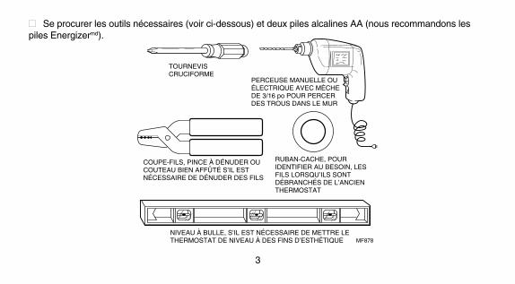
■■ Se procurer les outils nécessaires (voir ci-dessous) et deux piles alcalines AA (nous recommandons lespiles Energizermd).
2
TOURNEVIS CRUCIFORME
PERCEUSE MANUELLE OU ÉLECTRIQUE AVEC MÈCHE DE 3/16 po POUR PERCER DES TROUS DANS LE MUR
COUPE-FILS, PINCE À DÉNUDER OU COUTEAU BIEN AFFÛTÉ S’IL EST NÉCESSAIRE DE DÉNUDER DES FILS
RUBAN-CACHE, POUR IDENTIFIER AU BESOIN, LES FILS LORSQU’ILS SONT DÉBRANCHÉS DE L’ANCIEN THERMOSTAT
NIVEAU À BULLE, S’IL EST NÉCESSAIRE DE METTRE LE THERMOSTAT DE NIVEAU À DES FINS D’ESTHÉTIQUE MF878
1 Compatible avec les vannes de zone bifilaires de Honeywell. Un relais d’isolement est nécessaireavec les vannes de zone trifilaires. Non compatible avec les vannes bifilaires no 1361 de White Rodgers.
Avant l’installation■■ Consulter le tableau 1 afin de s’assurer que le thermostat est compatible avec le système choisi. S’il neconvient pas, le retourner au détaillant. Pour de plus amples renseignements, communiquer, sans frais, avecles Services à la clientèle au numéro 1-800-468-1502.
TABLEAU 1 - TABLEAU DE COMPATIBILITÉType de système compatible avec le CT3200
Gaz - veilleuse permanente ouiGaz - allumage électronique ouiChaudières à gaz oui 1Gaz - tension millivolt nonChaudières à mazout oui 1Appareils de chauffage au mazout ouiAppareils de chauffage électrique ouiConditionneur d’air électrique ouiPlinthes chauffantes électriques (120/240 V tension secteur) nonPompes à chaleur/systèmes multi-étages non
3
ÉTAPE 1
Non compatible avec tout circuit 120/240 V.Ne fonctionnera pas efficacement avec les systèmes à vapeur et à différence de densité.
■■ Se procurer les outils nécessaires (voir ci-dessous) et deux piles alcalines AA (nous recommandons lespiles Energizermd).
2
TOURNEVIS CRUCIFORME
PERCEUSE MANUELLE OU ÉLECTRIQUE AVEC MÈCHE DE 3/16 po POUR PERCER DES TROUS DANS LE MUR
COUPE-FILS, PINCE À DÉNUDER OU COUTEAU BIEN AFFÛTÉ S’IL EST NÉCESSAIRE DE DÉNUDER DES FILS
RUBAN-CACHE, POUR IDENTIFIER AU BESOIN, LES FILS LORSQU’ILS SONT DÉBRANCHÉS DE L’ANCIEN THERMOSTAT
NIVEAU À BULLE, S’IL EST NÉCESSAIRE DE METTRE LE THERMOSTAT DE NIVEAU À DES FINS D’ESTHÉTIQUE MF878

4
5
Retrait de l’ancien thermostat
Le thermostat n’est pas compatible avec de telssystèmes. Retourner le thermostat au détaillant.Pour obtenir des renseignements quant auxthermostats compatibles avec votre système,communiquer avec les Services à la clientèle deHoneywell au numéro 1-800-468-1502.
Thermostat à trois fils?Si vous avez trois fils pour le chauffage
seulement et que vous pouvez utiliser lecommutateur ON pour faire fonctionner leventilateur, ce thermostat fonctionnera avec votresystème. Cependant, quelques systèmes dechauffage à eau chaude (par zone) possèdent desthermostats trifilaires. Il faudra alors installer unrelais d’isolement sinon le thermostat nefonctionnera pas. Pour plus de renseignements,communiquer avec les Services à la clientèle aunuméro 1-800-468-1502.
■■ Vérifier si les systèmes de chauffage et derefroidissement fonctionnent correctement. Sil’un d’eux ne fonctionne pas, communiqueravec votre représentant en systèmes dechauffage et de refroidissement. Pour ne pasendommager le compresseur, ne pas fairefonctionner le système de refroidissementlorsque la température extérieure est inférieureà 10 °C (50°F).■■ COUPER L’ALIMENTATION du système àl’appareil de chauffage ou au panneau dedisjoncteurs ou des fusibles.■■ Déballer minutieusement votre nouveauthermostat et la plaque de montage; conserverles vis, les directives et le reçu.■■ Enlever le couvercle de l’ancien thermostat.S’il ne s’enlève pas lorsqu’on le tire fermement
par le bas, vérifier si une vis ne le retient pas enplace.■■ Desserrer les vis qui retiennent le thermostatà la plaque de montage, à la plaque murale ouau mur et soulever le thermostat.■■ Débrancher les fils de l’ancien thermostat oude la plaque de montage. Étiqueter les fils àl’aide de ruban-cache en inscrivant la lettrecorrespondant à l’ancienne borne. S’il n’y a
ÉTAPE 2
Un ou deux fils en trop?Si vous remplacez un thermostat Chronotherm
de Honeywell, vous trouverez peut-être un oudeux fils qui doivent être raccordés aux bornes del’horloge sur la plaque murale du thermostatChronotherm. Ces fils ne doivent pas se touchersinon le transformateur pourrait être endommagé.Débrancher les fils et les couvrir séparément deruban adhésif pour fils électriques. Ne pas lesenrouler ensemble. Placer les fils à un endroit oùils ne nuiront pas au fonctionnement du nouveauthermostat. Inscrire la couleur et la lettre repèredes autres fils.
Six fils ou plus?Si six fils ou plus sont présents (à l’exclusion
des fils de l’horloge reliés aux bornes), vous êtesprobablement en présence d’un thermostat pourpompe à chaleur ou pour système multi-étage.
que deux fils, il n’estpas nécessaire de lesétiqueter. Enrouler lesfils autour d’un crayonpour empêcher qu’ilsne tombent dans lemur (voir illustrationci-dessous).
FILS PARL’OUVERTUREDU MUR
MF5136

6
indiquer que le thermostat et le système dechauffage ou de refroidissement ne fonctionnentplus car les piles sont presque complètementdéchargées.Lorsque les piles seront vraiment mortes,l’indication «bAt Lo» disparaîtra et plus rien nesera affiché.Pour remplacer les piles, appuyer sur l’extrémitégauche des piles pour les enlever. Insérer lesnouvelles piles en s’assurant de l’orientation des
7
ÉTAPE 3 Installation des piles
Lorsque vos piles commenceront à être faibles, unvoyant bAt Lo clignotera 1 à 2 mois avant que lespiles ne soient complètement mortes. Remplacerles piles aussitôt que possible après avoirconstaté que le voyant clignote. Si les piles nesont pas remplacées alors que le voyant clignote,le voyant finira par ne plus clignoter. L’affichage«bAt Lo» restera à l’écran sans clignoter pour
bornes négative et positive. Si cette manoeuvrene prend pas plus de 20 à 30 secondes, lethermostat n’aura pas besoin d’êtrereprogrammer.Cependant, si l’affichage n’apparaît pas, les pilessont mortes ou incorrectement installées. Lareprogrammation du thermostat sera alorsnécessaire (Voir pages 12-13).
IMPORTANTQuoique le thermostat soit muni d’unindicateur de faible intensité, les pilesdevraient être remplacées une fois par annéepour éviter que le thermostat et le systèmede chauffage ou de refroidissement nes’arrêtent en raison de piles mortes.
Si vous quittez la maison pour une longuepériode, changer les piles avant de partir afind’éviter que le thermostat ne s’arrête en raison depiles mortes.
Les piles sont nécessaires au fonctionnementet à la programmation du thermostat.
IMPORTANT
■■ Se procurer deux piles alcalines AA (les autrestypes de piles ne dureront pas aussi longtemps;nous recommandons les piles Energizermd).
■■ S’assurer que le thermostat est à laposition OFF.
■■ Utiliser une pièce de monnaie pour ouvrir laporte du compartiment de piles.
■■ Installer deux piles alcalines AA tel qu’illustré, ens’assurant que les bornes négative et positive sontinstallées dans le bon sens.
■■ Remettre la porte en place.
INSTALLER DEUX PILES ALCALINES AA TEL QU’ILLUSTRÉ
MF1713
REMOVINGBATTERYDOOR
9PROGRAMMATION
Programmation du thermostat
8
nécessaire de programmer une heure et unetempérature pour toutes les périodes. Parexemple, il n’est pas nécessaire de programmer lespériodes LEAVE et RETURN, lorsqu’ily a quelqu’un à la maison durant les joursde la semaine.
Toujours appuyer sur les touches avec le boutdu doigt ou avec la gomme à effacer quelqu’unà la maison durant les jours de la semaine.
Toujours appuyer sur les touches avec le boutdu doigt ou avec la gomme à effacer d’uncrayon. Des instruments pointus tels les ongles oula pointe d’un crayon peuvent endommagerle clavier.
Lorsqu’on fait une erreur lors de la programmation,il suffit d’appuyer sur RUN PROGRAM et continuerà l’endroit où l’on n’est rendu.
“SLEEP” correspond à la période pendantlaquelle on peut abaisser la température(en hiver) ou élever la température (en été)pour économiser l’énergie pendant que lafamille dort. (Il arrive parfois que l’on préfère nepas élever la température en été afin que lesoccupants de la maison puissent dormirau frais.)
Programmer les heures et les températuresvoulues pour les jours de la semaine et pour lesjours de fin de semaine puisque les besoins enchauffage ou en refroidissement serontprobablement différents pour ces deux périodes.Si on désire ne pas programmer le thermostat, ilréglera automatiquement la température à 20 °C(68 °F) pour le chauffage et à 26 °C (78 °F) pourle refroidissement et ce, toute la journée. Deplus, selon l’horaire des occupants, il n’est pas
Une fois les piles installées, vous pouvezfacilement programmer le thermostat dans votremain avant de l’installer au mur.
Si vous préférez programmer le thermostat aprèsl’avoir installé au mur, vous devez passerdirectement à la page 16. Vous reviendrez à cettesection par la suite.
Le tableau de programmation apparaissant auxpages 10 et 11 constitue une excellente occasionde planifier votre programme des réglages desheures et des températures pour les différentespériodes de la journée.
Quatre périodes de programmation sontoffertes pour les jours de la semaine - WAKE,LEAVE, RETURN et SLEEP. Chacune de sespériodes peut être affichée en appuyant sur latouche SET SCHEDULE.
“WAKE” correspond à la période pendantlaquelle vous désirez que la températurede la maison soit confortable lorsque la famillese lève et se prépare à partir pour le travail oul’école. (La température de la pièce sera plusélevée en hiver et moins élevéeen été.)“LEAVE” correspond à une période pendantlaquelle on peut abaisser la température (enhiver) ou élever la température (en été) pouréconomiser l’énergie pendant que la famille estau travail ou à l’école.“RETURN” correspond à la période pendantlaquelle vous désirez que la température dela maison soit confortable pour les activitésfamiliales avant l’heure du coucher, c’est-à-dire plus élevée en hiver et moins élevéeen été.
ÉTAPE 4
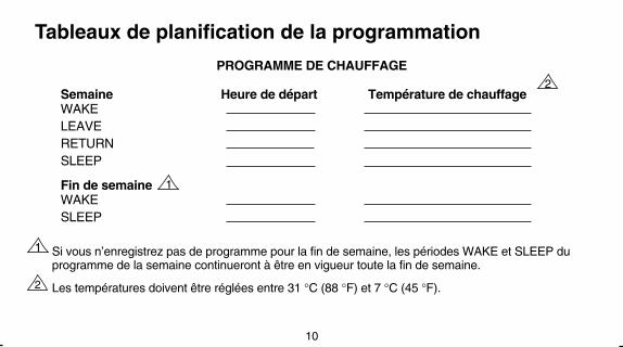
PROGRAMME DE CHAUFFAGE
Semaine Heure de départ Température de chauffageWAKELEAVERETURNSLEEP
Fin de semaineWAKESLEEP
1 Si vous n’enregistrez pas de programme pour la fin de semaine, les périodes WAKE et SLEEP duprogramme de la semaine continueront à être en vigueur toute la fin de semaine.
2 Les températures doivent être réglées entre 31 °C (88 °F) et 7 °C (45 °F).
PROGRAMME DE REFROIDISSEMENT
Semaine Heure de départ Température de chauffageWAKELEAVERETURNSLEEP
Fin de semaineWAKESLEEP
1 Si vous n’enregistrez pas de programme pour la fin de semaine, les périodes WAKE et SLEEP duprogramme de la semaine continueront à être en vigueur toute la fin de semaine.
2 Les températures doivent être réglées entre 31 °C (88 °F) et 7 °C (45 °F).
REMARQUE : Si vous décidez de ne pas programmer votre thermostat, le réglage de la températurede chauffage sera automatiquement à 20 °C (68 °F) et celui du refroidissement sera automatiquement à26 °C (78 °F) toute la journée.
11PROGRAMMATION
10
Tableaux de planification de la programmation
1
1
2
2

13
Programme de chauffageLe commutateur en position HEAT, appuyer une fois sur . L’affichage indiquera “WAKE”.
Utiliser les touches pour programmer l’heure et les touches pour
PROGRAMMATION
Ce guide peut servir à programmer votre thermostat.
REMARQUE : Les piles sont nécessaires pour programmer et faire fonctionner le thermostat. Lorsde l’installation des piles, régler le commutateur du système à OFF. Enlever la porte ducompartiment de piles (côté gauche du thermostat) en utilisant une pièce de monnaie. Suivre lesdirectives des pages 6 et 7.
Réglage de l’heure et du jour
Appuyer une fois sur et , pour régler l’heure; répéter pour régler le jour,
puis appuyer sur .
SetSchedule
12
SetClock/Day
Ahead
Back
Time
Warmer
Cooler
Temp
programmer la température de la période “WAKE” du lundi au vendredi. Refaire pour les périodes“LEAVE”, “RETURN”, “SLEEP”.
Appuyer sur , jusqu’à ce que “SA-SU” apparaisse à l’écran. Utiliser les touches
pour programmer l’heure et les touches pour programmer la température de la période
WAKE pour le samedi et le dimanche. Refaire pour la période SLEEP.
SetSchedule
Ahead
Back
Time
Ahead
Back
Time
SetClock/Day
Programme de refroidissementLe commutateur en position COOL, répéter les étapes du programme de chauffage.
Après la programmation, régler les commutateurs du ventilateur
et du système au besoin, Appuyer une fois sur pour que le programme commence.RunProgram

15
Pour vérifier le réglage actuel de la température — . (Si les commandes TEMPO
RARILY CHANGE ou HOLD sont en cours, en appuyant sur cette touche, ces commandesseront annulées.)
Pour vérifier les programmes — appuyer sur jusqu’à ce que toutes les
heures et les températures programmées aient été affichées.
Pour annuler un programme, appuyer sur jusqu’à ce que le programme voulu
apparaisse; puis, appuyer simultanément sur . .
Pour modifier temporairement la température pour la période en cours seulement —
appuyer sur ; cette commande s’annulera lors de la prochaine période
programmée ou pour l’annuler en tout temps, appuyer sur .
Pour maintenir une température indéfiniment — appuyer sur et ; pour
annuler cette commande, appuyer sur .
PROGRAMMATION
Ce guide peut servir à faire rapidement des modifications à la programmation duthermostat programmer.
REMARQUE : le commutateur du système doit à la position HEAT ou COOL avantde passer aux étapes suivantes.
14
RunProgram
SetSchedule
Questions?Communiqueravec les Servicesà la clientèle deHoneywellau numéro1-800-468-1502.
Warmer
Cooler
Temp
RunProgram
HoldTemp
Warmer
Cooler
Temp
RunProgram
RunProgram
SetSchedule
Pour retourner au programme habituel ou pour commencer
un programme appuyer sur .RunProgram
Ahead
Back
Time
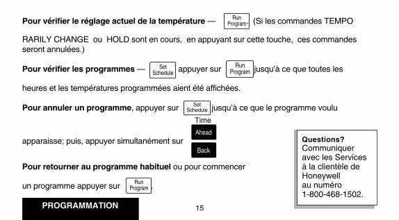
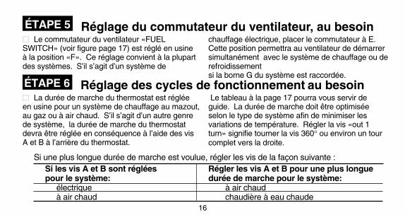
Réglage du commutateur du ventilateur, au besoin
Si les vis A et B sont réglées Régler les vis A et B pour une plus longuepour le système: durée de marche pour le système:
électrique à air chaudà air chaud chaudière à eau chaude
INSTALLATION
16
17
Réglage des cycles de fonctionnement au besoin
■■ Le commutateur du ventilateur «FUELSWITCH» (voir figure page 17) est réglé en usineà la position «F». Ce réglage convient à la plupartdes systèmes. S’il s’agit d’un système de
chauffage électrique, placer le commutateur à E.Cette position permettra au ventilateur de démarrersimultanément avec le système de chauffage ou derefroidissementsi la borne G du système est raccordée.
■■ La durée de marche du thermostat est régléeen usine pour un système de chauffage au mazout,au gaz ou à air chaud. S’il s’agit d’un autre genrede système, la durée de marche du thermostatdevra être réglée en conséquence à l’aide des visA et B à l’arrière du thermostat.
Le tableau à la page 17 pourra vous servir deguide. La durée de marche doit être optimiséeselon le type de système afin de minimiser lesvariations de température. Régler la vis «out 1turn» signifie tourner la vis 360° ou environ un tourcomplet vers la droite.
Si une plus longue durée de marche est voulue, régler les vis de la façon suivante :
ÉTAPE 5
ÉTAPE 6
REMARQUE: Le thermostat ne possède pas de réglages pour les systèmes à vapeur ou à différence dedensité. Les cycles de fonctionnement ne seraient pas assez long pour une régulation précise de latempérature.
IMPORTANTLorsqu’on utilise un appareil dechauffage à haut rendement (tel unsysteme dont la consommationmoyenne de combustible [AFUE]est de 90% ou plus), tourner la visA 1 tour vers la droite et la vis Bvers la gauche.
R Rc
W Y G
B D
A C
ARRIÈRE DU THERMOSTAT
MF1708
DISPLAY °FDISPLAY °C
C–INC–OUT1 TURN
FOR HIGH EFFICIENCY FURNACE (90%+ AFUE)ADJUST: SCREW A–OUT 1 TURN
SCREW B–INFUEL SWITCH – F POSITION
F E
FUEL SWITCH
WARM AIRFURNACEHOT WATERBOILERELECTRIC FURNACE
A–IN
A–OUT1 TURNA–IN
ADJUST SCREWS THROUGH HOLESTO SELECT OPERATION DESIRED
B–IN
B–IN
B–OUT1 TURN
FUEL SWITCHPOSITION
F
F
E
HEATING SYSTEM
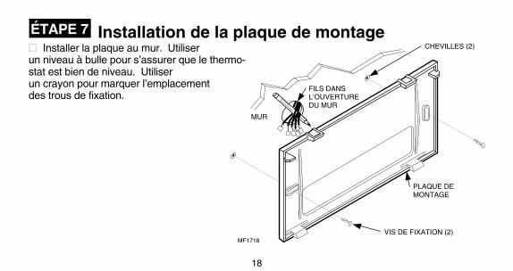
Installation de la plaque de montage
19
18
INSTALLATION
■■ Installer la plaque au mur. Utiliserun niveau à bulle pour s’assurer que le thermo-stat est bien de niveau. Utiliserun crayon pour marquer l’emplacementdes trous de fixation.
■■ Retirer la plaque du mur et percer des trousde 3/16 po dans un mur à maçonnerie sècheaux endroits indiqués. S’il s’agit d’un mur deplâtre ou de bois, percer des trous de 7/32 poaux endroits indiqués. Pousser doucement lesboulons d’ancrage (fournies) dans le murjusqu’à ce qu’ils soient au ras du mur.
■■ Replacer la plaque de montage sur les trousen tirant les fils par l’ouverture du mur. Insérerles deux vis de fixation dans les trous.
■■ Mettre de niveau le thermostat (questiond’esthétique); le thermostat fonctionneranormalement même s’il n’est pas de niveau.Serrer les vis.
ÉTAPE 7
MUR
FILS DANS L’OUVERTURE DU MUR
CHEVILLES (2)
PLAQUE DE MONTAGE
VIS DE FIXATION (2)MF1718
NIVEAU À BULLE
MF1714
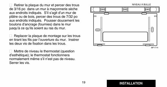

TABLEAU 2 - COULEURS DES FILS ET FONCTIONSBORNE DU RACCORDER AU
THERMOSTAT FIL COULEURa FONCTIONG Vert VentilationY Jaune RefroidissementW Blanc ChauffageRc Bleu Alimentation
refroidissementR Rouge Alimentation
chauffage
INSTALLATION
20
21
Raccordement Des Bornes Du ThermostatREMARQUE: Tout le câblage doit être conforme
aux codes et règlements locaux. Si vous n’êtespas certain des méthodes de raccordement,communiquez avec votre entrepreneur enconditionnement d’air.
À l’aide des étiquettes de ruban-cache installéessur les fils lors du retrait de l’ancien thermostat,
faire correspondre la lettre du fil de l’ancienthermostat à la borne portant la même lettre àl’arrière de votre nouveau thermostat. Consulter lesfigures apparaissant aux pages 22-23 et le tableau2 pour obtenir des renseignementssupplémentaires et les couleurs des fils. Tenir lethermostat de la façon indiquée pour éviterl’utilisation de prolongateurs de fil. Si les fils sont
tout de même trop courts, utiliserdes connecteurs pour allongerles fils (non compris). Voir lafigure ci-contre pour savoircomment utiliser lesprolongateurs de fils.■■ Il est nécessaire d’enleverle cavalier installé en usine etservant à raccorder les bornesR et RC que dans les applica-tions à 5 fils seulement.
aCouleurs standard; vérifier les raccordements del’équipement de chauffage-refroidissement.
■■ Boucher le trou dans le mur avec un isolantpour éviter que des courants d’air affecte lefonctionnement du thermostat.
■■ Desserrer les vis des bornes et glisser chaquefil sous sa borne correspondante. Voir la figuredans le coin inférieur droit pour la techniqued’insertion des fils. Resserrer les bornesminutieusement.
MF1715
CONNECTEUR POUR DEUX FILS DE CALIBRE 18
FIL PROVENANT DU MUR
152 mm (6 po) DE FIL DE THERMOSTAT CALIBRE 18. FAIRE CORRESPONDRE LES COULEURS DE L’ISOLANT OU MARQUER L’EXTRÉMITÉ DES FILS
MF1712
CAVALIER (INSTALLÉ EN USINE)INSÉRER
DIRECTEMENT SOUS LA TÊTE DE LA VIS
DÉNUDER DE 8 mm(5/16 po)
EXTRÉMITÉ VISIBLE DU FIL ICI
RRc
WYG
M3002A
PROPER WIRING TECHNIQUE
ÉTAPE 8
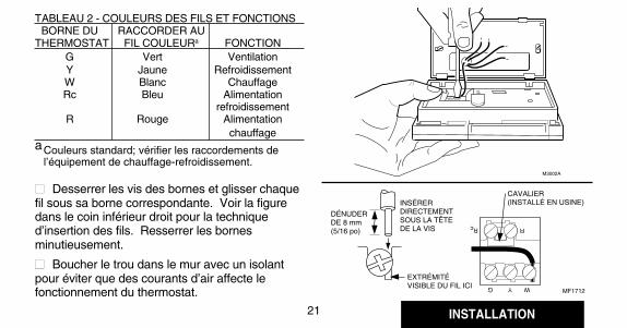

22
23 INSTALLATION
R Rc
W Y G
B D
A C
4 FILS - CHAUFFAGE - REFROIDISSEMENT (CAVALIER INTACT)
L1 (SOUS TENSION)
L2
ALIMENTATION. FOURNIR, AU BESOIN, UN DISPOSITIF DE COUPURE ET UNE PROTECTION CONTRE LES SURCHARGES.
1
CAVALIER
RELAIS DE CHAUFFAGE OU BOBINE DE VANNE
MF1710A
BOBINE DU CONTACTEUR DE REFROIDISSEMENT
RELAIS DU VENTILATEUR
R Rc
W Y G
B D
A C
DEUX FILS - CHAUFFAGE SEULEMENT (CAVALIER INTACT)
MF1709A
L1 (SOUSTENSION)
L2
ALIMENTATION. FOURNIR, AU BESOIN, UN DISPOSITIF DE COUPURE ET UNE PROTECTION CONTRE LES SURCHARGES.
1
1RELAIS DE CHAUFFAGE OU BOBINE DE VANNE
CAVALIER
R Rc
W Y G
B D
A C
5 FILS - CHAUFFAGE-REFROIDISSEMENT (CAVALIER ENLEVÉ)
L1 (SOUS TENSION)
L2
ALIMENTATION. FOURNIR, AU BESOIN, UN DISPOSITIF DE COUPURE ET UNE PROTECTION CONTRE LES SURCHARGES.
1
MF1711A
L2
BOBINE DU CONTACTEUR DE REFROIDISSEMENT
RELAIS DU VENTILATEUR
RELAIS DE CHAUFFAGE OU BOBINE DE VANNE
1 1
L1 (SOUS TENSION)
R Rc
W Y G
B D
A C
3 FILS - REFROIDISSEMENT SEULEMENT (CAVALIER INTACT)
L1 (SOUS TENSION)
L2
ALIMENTATION. FOURNIR, AU BESOIN, UN DISPOSITIF DE COUPURE ET UNE PROTECTION CONTRE LES SURCHARGES.
1
CAVALIER
MF848
BOBINE DU CONTACTEUR DE REFROIDISSEMENT
RELAIS DU VENTILATEUR
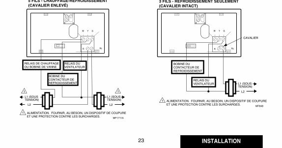
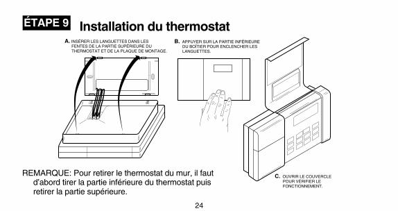
24
25
CHAUFFAGENe PAS vérifier le fonctionnementdu système de chauffage en installantun cavalier entre les bornes du thermo-stat au régulateur primaire tel la vanne àgaz, la vanne de zone ou le régulateurdu brûleur au mazout car le thermostatpourrait être endommager.
INSTALLATION
ÉTAPE 9
ÉTAPE 10 Vérification du fonctionnement aprèsla programmation et l’installation
WarmerAppuyer sur cette touche jusqu’à ce quela température soit environ 6 °C (10 °F)au-dessus de la température ambiante.Le système de chauffage devrait semettre en marche et le ventilateur devraitdémarrer après quelques instants(immédiatement si le commutateur duventilateur est à la position E).
Appuyer sur cette touche jusqu’à ce quela température soit environ 6 °C (10 °F)sous la température ambiante. Lesystème de chauffage devrait s’arrêter.
HeatCool Off
Auto On
Déplacer lecommutateur dusystème à HEAT etle commutateur duventilateur à AUTO.
Cooler
Installation du thermostat
MF1734
B. APPUYER SUR LA PARTIE INFÉRIEURE DU BOÎTIER POUR ENCLENCHER LES LANGUETTES.
C. OUVRIR LE COUVERCLE POUR VÉRIFIER LE FONCTIONNEMENT.
A. INSÉRER LES LANGUETTES DANS LES FENTES DE LA PARTIE SUPÉRIEURE DU THERMOSTAT ET DE LA PLAQUE DE MONTAGE.
REMARQUE: Pour retirer le thermostat du mur, il fautd’abord tirer la partie inférieure du thermostat puisretirer la partie supérieure.
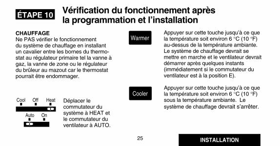

26
27
position COOL et le commutateur duventilateur à AUTO.
Appuyer sur cette touche jusqu’à ce quela température soit environ 6 °C (10 °F)sous la température ambiante. Lesystème de refroidissement et leventilateur devraient se mettre en marche.
Appuyer sur cette touche jusqu’à ce quela température soit environ 6 °C (10 °F)au-dessus de la température ambiante.Le système de refroidissement et leventilateur devraient s’arrêter.
Déplacer le commutateur du système àOFF et le commutateur du ventilateur àAUTO. Le système et le ventilateurdevraient être arrêtés.
INSTALLATION
HeatCool Off
Auto On
REFROIDISSEMENTPour éviter d’endommager lecompresseur, ne pas faire fonctionnerle système de refroidissement lorsquela température extérieure est inférieure à10 °C (50 °F). Pour plus de renseignements,consulter la documentation du fabricantdu compresseur.
REMARQUE: Lorsque le point de consignedu refroidissement est modifié, lethermostat peut prendre jusqu’à 5 minutesavant de mettre en marche le système derefroidissement. Cette temporisation apour but de protéger le compresseur.
Déplacer le commutateur du système à la
ÉTAPE 11 Réglage des commutateurs du
système et du ventilateur
Cooler
Warmer
HeatCool Off
Auto On
Auto On
HeatCool Off
FAN AUTO: Réglage normal pour la plupart desrésidences. Un ventilateur à une vitesse se mettraen marche automatiquement lorsque le système dechauffage ou de refroidissement fera de même. Unventilateur à deux vitesses fonctionnerahabituellement à régime élevé lorsque le système derefroidissement fonctionnera et à bas régime lorsquele système de chauffage fonctionnera.FAN ON: Le ventilateur fonctionne de façoncontinue. Améliore la circulation d’air lorsd’occasions spéciales et permet une meilleurefiltration de l’air.COOL: Le thermostat commande le système derefroidissement.OFF: Les systèmes de chauffage et derefroidissement sont arrêtés.HEAT: Le thermostat commande le système dechauffage.
Auto On
HeatCool Off
HeatCool Off
Puis régler le commutateur dusystème.
Régler tout d’abord lecommutateur du ventilateur.
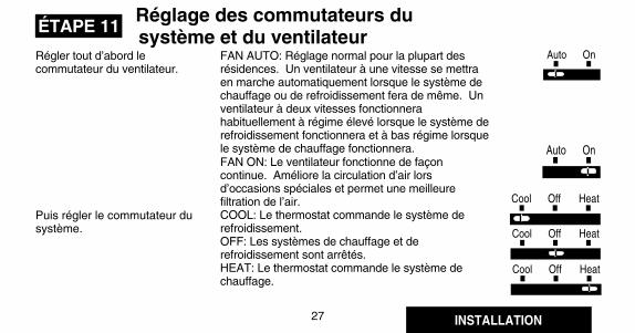
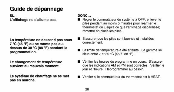
29
28
Guide de dépannageSi…L’affichage ne s’allume pas.
La température ne descend pas sous7 °C (45 °F) ou ne monte pas au-dessus de 30 °C (88 °F) pendant laprogrammation.
Le changement de températuresurvient au mauvais moment.
Le système de chauffage ne se metpas en marche.
DONC…■ Régler le commutateur du système à OFF; enlever le
piles pendant au moins 5 minutes pour réarmer lethermostat ou jusqu’à ce que l’affichage disparaisse;remettre en place les piles.
■ S’assurer que les piles sont bonnes et installéescorrectement.
■ La limite de température a été atteinte. La gamme sesitue entre 7 et 30 °C (45 à 88 °F).
■ Vérifier les heures du programme en cours. S’assurerque les indications AM et PM sont correctes. Vérifier lejour et l’heure. Reprogrammer au besoin.
■ Vérifier si le commutateur du thermostat est à HEAT.
■ Si le réglage de la température est plus élevé que latempérature actuelle et que le voyant SYSTEM ON estallumé, communiquer avec les Services à la clientèle deHoneywell au 1-800-468-1502.
■ Vérifier si le commutateur du thermostat est à la positionCOOL.
■ Vérifier les fusibles ou le disjoncteur du système. Lesremplacer et les réenclencher au besoin. Si l’affichagen’indique rien ou «bAt Lo», changer les piles.
■ Le thermostat est muni d’une temporisation pour lerefroidissement. Après une modification au programmede refroidissement, le système peut prendre de 5 à 10minutes avant de se mettre en marche.
■ Si le réglage de la température est moins élevé que latempérature actuelle et que le voyant SYSTEM ON estallumé, déplacer le commutateur du système de COOL à
Le système de refroidissement nese met pas en marche.

31
30
OFF pour 10 minutes. Après ces 10 minutes, remettrele commutateur à la position COOL. Si le système derefroidissement se met en marche, peut-être lecompresseur avait-il atteint son seuil haut de protectionet s’était arrêté. Si le système de refroidissement nese met pas en marche après 10 minutes et que levoyant SYSTEM ON est allumé, communiquer avecles Services à la clientèle de Honeywell au 1-800-468-1502.
■ S’il s’agit d’un thermostat à 2 ou 4 fils, vérifier si lecavalier entre R et RC est installé.
■ Appuyer sur RUN PROGRAM pour vérifier le réglageactuel de la température.
■ Au besoin, changer le réglage de la température. Voirpage 14.
■ Permettre au système de chauffage et au ventilateurde se mettre en en marche avant de vérifier aux grillesà registre. (Vérifier si le cycle de fonctionnement dusystème est bien réglé conformément aux directivesde la page 16).
■ Vérifier le réglage du système au dos du thermostat.
■ Réajuster conformément aux directives des pages16 et 17.
■ Vérifier si le trou où passent les fils derrière la plaquede montage a été bouché avec de l’isolant pour éviterles courants d’air qui pourraient affecter lefonctionnement du thermostat.
■ Le réglage en cours et la température affichée peuventdifférer à l’occasion.
Le système de refroidissement ne semet pas en marche.
La température de la maison est tropchaude ou trop froide.
Le voyant SYSTEM ON est allumémais qu’aucune chaleur ne provientdes grilles à registre.
Les cycles de fonctionnement dusystème de chauffage ou derefroidissement sont trop fréquents.
Les cycles de fonctionnement dusystème sont trop longs ou tropcourts.
Le réglage en cours du thermostat necorrespond pas à la températureaffichée.
32
Ligne directe sans fraisSi vous avez des questions concernant ce thermostat, vous devez lire et suivre les directives de
ce manuel. Pour obtenir des renseignements supplémentaires, communiquez avec les Services àla clientèle au 1-800-468-1502, du lundi au vendredi de 7 h à 17 h 30.
Avant d’appeler, assurez-vous de connaître le numéro de modèle du thermostat, le code dedate, le type de système de chauffage ou refroidissement (c.-à-d. eau chaude, air chaud, mazout,gaz, etc.) et le nombre de fils raccordés au thermostat.
33
AVISCet appareil est un dispositif numérique de classe B conforme aux normes de la CanadianRadio Interference, CRC c.1374.
Si le produit est défectueux, le consommateur(i) doit le retourner au magasin où cet appareil a été acheté, ou(ii) doit l’emballer avec soin et y joindre une preuve d’achat (indiquant la date d’achat) ainsi qu’une brève description du mauvais
fonctionnement, et l’envoyer par la poste (port payé) à l’adresse suivante :Honeywell Inc. Au Canada : Honeywell Limited/Honeywell LimitéeReturn Goods Department Product Services ON15-FFE1050 Berkshire Lane 740 Ellesmere RoadPlymouth, MN 55441-4437 Scarborough, Ontario M1P 2V9
La présente garantie ne couvre pas les frais d’installation et de retrait de ce produit. La présente garantie ne s’appliquera pas s’il est démontrépar Honeywell que la défectuosité ou le mauvais fonctionnement du produit est dû à un endommagement du produit alors que le consommateurl’avait en sa possession.
La responsabilité de Honeywell se limite à réparer ou à remplacer le produit conformément aux modalités susmentionnées. HONEYWELLN’ASSUME AUCUNE RESPONSABILITÉ POUR QUELQUE DOMMAGE INDIRECT QUE CE SOIT RÉSULTANT D’UNE VIOLATIONQUELCONQUE D’UNE GARANTIE, EXPRESSE OU TACITE, APPLICABLE AU PRÉSENT PRODUIT. Certains territoires et provinces nepermettent pas l’exclusion ou la restriction des dommages indirects et, par conséquent, la présente restriction peut ne pas s’appliquer.
LA PRÉSENTE GARANTIE TIENT LIEU DE TOUTES LES AUTRES GARANTIES, EXPRESSES OU TACITES, ET LES GARANTIES DEVALEUR MARCHANDE ET DE CONFORMITÉ À UNE FIN PARTICULIÈRE SONT PAR LES PRÉSENTES EXCLUESAPRÈS LA PÉRIODE D’UN AN DE LA PRÉSENTE GARANTIE. Certains territoires et provinces ne permettent pas de limiter la durée desgaranties tacites et, par conséquent, la présente limitation peut ne pas s’appliquer.
La présente garantie donne au consommateur des droits légaux spécifiques et peut-être certains autres droits qui peuvent varier selon la provinceou le territoire.
Pour tout renseignement concernant cette garantie, veuillez écrire au Customer Assistance Department, Honeywell Inc., P.O. Box 524, MN27-2164 Minneapolis, MN55440-0524, ou appeler les Services à la clientèle de Honeywell, en utilisant la ligne directe 1-800-468-1502, du lundiau vendredi, de 7 h à 17 h 30. Au Canada, veuillez écrire à Honeywell Limitée-Honeywell Limited, Retail Products, ON15-02H, 740, EllesmereRoad, Scarborough (Ontario) M1P 2V9.
GARANTIE RESTREINTE POUR UN ANHoneywell Limitée garantit au consommateur que ce produit au consommateur, excluant les piles, est exempt de tout vice de fabrication ou
de matière dans la mesure où il en est fait une utilisation et un entretien convenables et ce, pour une période d’un an (1) à compter de la premièredate d’achat par un consommateur. En cas de défectuosité ou de mauvais fonctionnement pendant la période de garantie, Honeywell répareraou remplacera ledit produit (au choix de Honeywell) dans un délai raisonnable.
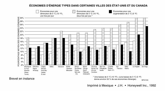
THERMOSTATPROGRAMMABLEDE HONEYWELL
MagicStatmd/T8132
Thermostat programmable et plaque de montagepour systèmes de chauffage et (ou) de
refroidissement avec programmation pour lasemaine et la fin de semaine
Modèle T8132
9-92 • Publication no 69-0740B—1
MANUEL DE PROGRAMMATIONET D’INSTALLATION
Brevet en instance
Imprimé à Mexique • J.H. • Honeywell Inc., 1992
30%
28%
26%
24%
22%
20%
18%
16%
14%
12%
8%
6%
2%
10%
4%
MinneapolisSt. PaulMontréal OttawaToronto
BuffaloClevelandMilwaukee
EdmontonReginaWinnipeg
CalgaryMonctonNorth BayQuébecSt-Jean
Halifax Vancouver DenverDes Moines OmahaSalt Lake City
BostonChicagoDetroitPittsburghIndianapolis
CincinnatiKansas CitySt-Louis Columbus
New YorkPhiladelphieSeattle
LouisvillePortlandWash. D.C.
San Francisco
DallasAtlanta
Los AngelesPO
UR
CE
NT
AG
E M
OY
EN
DE
S É
CO
NO
MIE
S D
'ÉN
ER
GIE
Économies pour une diminution de 5 °C (10 °F), une fois par jour
Économies pour une diminution de 5 °C (10 °F), deux fois par jour *
Économies pour une augmentation de 3 °C (5 °F)
ÉCONOMIES D'ÉNERGIE TYPES DANS CERTAINES VILLES DES ÉTAT-UNIS ET DU CANADA
* Une baisse de 5 °C (10 °F)—(une baisse de 3 °C (5 °F) donne environ 55 % de ces économies d'énergie). MF2416A
San Diego