67 Mustang Tilt-Away Steering Column Adjustment … Mustang/Article-67Tilt...ConcoursMustang.com 67...
8
ConcoursMustang.com 67 Mustang Tilt-Away Steering Column Adjustment & Repair NOTE: The following information was taken from Technical Service Bulletin #916 Dated October 21,1966
Transcript of 67 Mustang Tilt-Away Steering Column Adjustment … Mustang/Article-67Tilt...ConcoursMustang.com 67...
ConcoursMustang.com
67 Mustang Tilt-Away Steering Column Adjustment & Repair
NOTE: The following information was taken from Technical Service Bulletin #916 Dated October 21,1966
Page 2 1965 P aint Col ors ConcoursMustang.com Page 2 67 T i l t -S way St eeri ng Co lum n
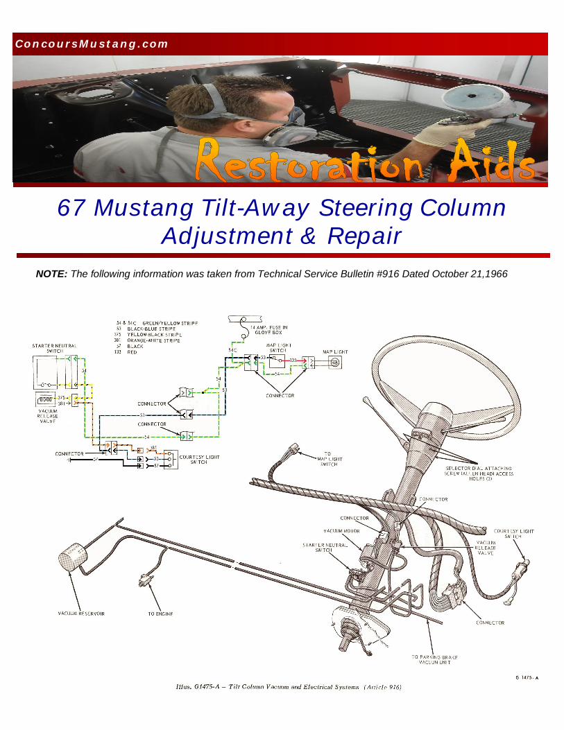
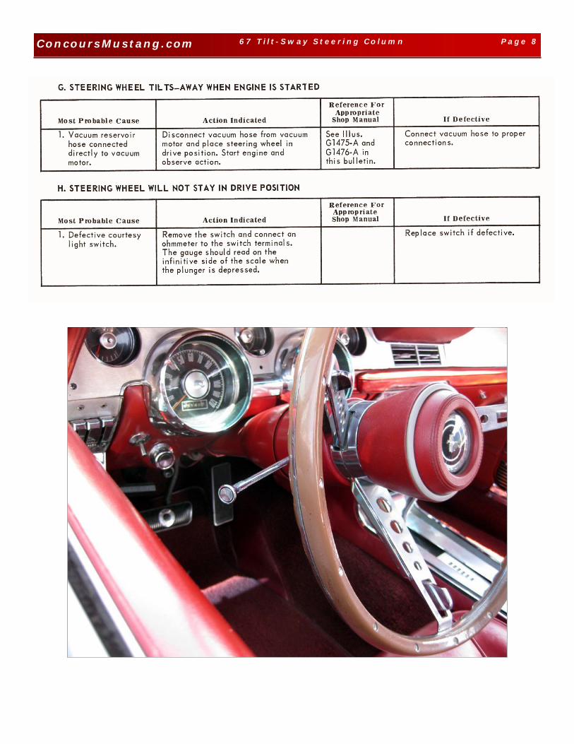
DESCRIPTION A dual-action (tilt-away type) steering column features nine driving positions (four up and four down from a center position) and a tilt-away position that is automati-cally accomplished when the ignition key is turned to the OFF position and the left door is opened. This com-pletes an electrical circuit through a switch in the left door jamb located just below the courtesy light switch and an electrically operated vacuum release valve mounted on the lower edge of the instrument panel ap-proximately eight inches to the right of the steering column (Illus. G1476-A). The vacuum release valve is con-nected to a vacuum reservoir located on the right side of the dash panel in the engine compartment and to a vacuum motor located on the lower end of the steering column tube by rubber hoses. When the vacuum re-lease valve is energized electrically, it opens a valve and allows reservoir vacuum to act on the vacuum motor diaphragm to pull the parking pawl out of the lower flange at the upper end of the column. Spring tension then moves the steering wheel up-ward and to the right at approxi-mately a 45 degree angle (tilt-away position) at the steering shaft univer-sal joint. The column will remain in the tilt-away position until the driver manually moves the column to the drive position after the left door has been closed. A starter safety switch lo-cated to the right of the vacuum mo-tor on the steering column prevents the engine from being started while the steering wheel is in the tilt-away position. The starter safety switch is actuated by the locking pawl. A tab provided on the rod depresses the switch to open the starter motor cir-cuit when the wheel is in the tilt po-sition. When the steering wheel is
placed in the drive position, the tab moves upward and allows the switch plunger to move upward and allows the switch plunger to move outward and close the circuit. The vacuum reservoir has a capacity STEERING to operate (cycle) the steering column for ap-proximately three times after the en-gine has been shut down. VACUUM MOTOR REMOVAL
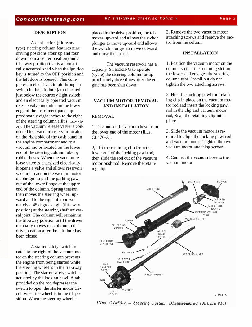
AND INSTALLATION REMOVAL 1. Disconnect the vacuum hose from the lower end of the motor (Illus. CL476-A). 2, Lift the retaining clip from the lower end of the locking pawl rod, then slide the rod out of the vacuum motor push rod. Remove the retain-ing clip.
3, Remove the two vacuum motor attaching screws and remove the mo-tor from the column.
INSTALLATION
1. Position the vacuum motor on the column so that the retaining slot on the lower end engages the steering column tube. Install but do not tighten the two attaching screws. 2. Hold the locking pawl rod retain-ing clip in place on the vacuum mo-tor rod and insert the locking pawl rod in the clip and vacuum motor rod, Snap the retaining clip into place. 3. Slide the vacuum motor as re-quired to align the locking pawl rod and vacuum motor. Tighten the two vacuum motor attaching screws. 4. Connect the vacuum hose to the vacuum motor.

Page 3 1965 P aint Col ors ConcoursMustang.com Page 3 67 T i l t -S way St eeri ng Co lum n
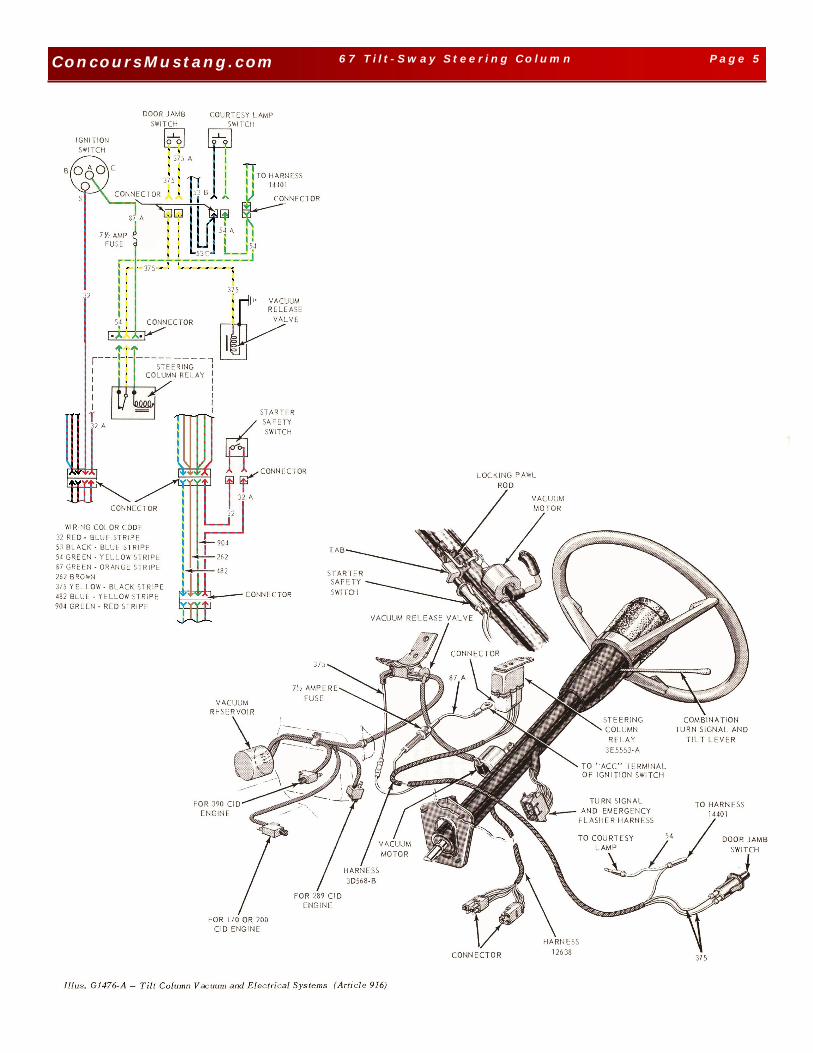
VACUUM RELEASE YALVE REMOVAL 1. Disconnect the wire from the vac-uum release valve terminal (Illus. G1476-A). 2. Disconnect the two vacuum hoses from the release valve. 3. Remove the bolt that attaches the vacuum release valve mounting bracket to the lower edge of the in-strument panel. Remove the vacuum release valve and mounting bracket. INSTALLATION 1. Position the vacuum release valve on thelower edge of the instrument panel so that the mounting bracket points upward and the one connector points toward the steering column. Secure the release valve bracket with the attaching bolt. 2. Connect the wire to the terminal at the rear of the valve. 3. Connect the reservoir hose to the connector at the rear of the valve. Connect the vacuum motor hose to the connector that points toward the steering column. 4. Start the engine and check the steering column operation.
STARTER SAFETY SWITCH
REMOVAL 1. Disconnect the two plug in type wires from the rear of the starter safety switch located on the right side of the column (Illus. G1476-A). 2. Remove the two switch attaching screws and remove the switch and bracket.
3. Remove the switch from the bracket. INSTALLATION 1. Assemble the starter safety switch in the bracket. 2. Position the starter safety switch and bracket on the column tube and in- stall but do not tighten the screws.
3. Place the steering wheel in the drive position and slide the switch forward or back on the steering col-umn tube to establish a clearance of 0.080 inch gap between the tab on the locking pawl rod and the switch plunger, then tighten the two attach-ing screws. 4. Connect the two wires to the rear of the switch being careful not to disturb the position of the switch in the bracket.
Page 4 1965 P aint Col ors ConcoursMustang.com Page 4 67 T i l t -S way St eeri ng Co lum n
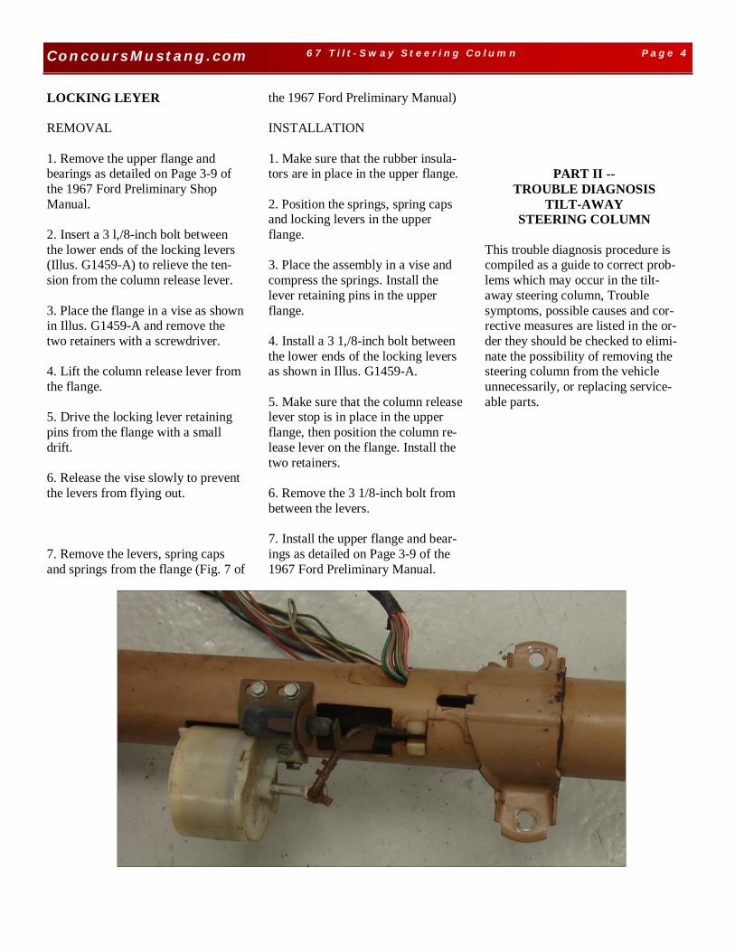
LOCKING LEYER REMOVAL 1. Remove the upper flange and bearings as detailed on Page 3-9 of the 1967 Ford Preliminary Shop Manual. 2. Insert a 3 l,/8-inch bolt between the lower ends of the locking levers (Illus. G1459-A) to relieve the ten-sion from the column release lever. 3. Place the flange in a vise as shown in Illus. G1459-A and remove the two retainers with a screwdriver. 4. Lift the column release lever from the flange. 5. Drive the locking lever retaining pins from the flange with a small drift. 6. Release the vise slowly to prevent the levers from flying out. 7. Remove the levers, spring caps and springs from the flange (Fig. 7 of
the 1967 Ford Preliminary Manual) INSTALLATION 1. Make sure that the rubber insula-tors are in place in the upper flange. 2. Position the springs, spring caps and locking levers in the upper flange. 3. Place the assembly in a vise and compress the springs. Install the lever retaining pins in the upper flange. 4. Install a 3 1,/8-inch bolt between the lower ends of the locking levers as shown in Illus. G1459-A. 5. Make sure that the column release lever stop is in place in the upper flange, then position the column re-lease lever on the flange. Install the two retainers. 6. Remove the 3 1/8-inch bolt from between the levers. 7. Install the upper flange and bear-ings as detailed on Page 3-9 of the 1967 Ford Preliminary Manual.
PART II -- TROUBLE DIAGNOSIS
TILT-AWAY STEERING COLUMN
This trouble diagnosis procedure is compiled as a guide to correct prob-lems which may occur in the tilt-away steering column, Trouble symptoms, possible causes and cor-rective measures are listed in the or-der they should be checked to elimi-nate the possibility of removing the steering column from the vehicle unnecessarily, or replacing service-able parts.
Page 5 1965 P aint Col ors ConcoursMustang.com Page 5 67 T i l t -S way St eeri ng Co lum n
Page 6 1965 P aint Col ors ConcoursMustang.com Page 6 67 T i l t -S way St eeri ng Co lum n

Page 7 1965 P aint Col ors ConcoursMustang.com Page 7 67 T i l t -S way St eeri ng Co lum n
Page 8 1965 P aint Col ors ConcoursMustang.com Page 8 67 T i l t -S way St eeri ng Co lum n