
65 - Champion Cutting Tool...
6
MEGABRUTE MAGNETIC DRILL PRESS PARTS & SCHEMATICS SAFETY / USAGE GUIDELINES RB 65E
-
Upload
doankhuong -
Category
Documents
-
view
215 -
download
1
Transcript of 65 - Champion Cutting Tool...

MEGABRUTEMAGNETIC DRILL PRESS
PARTS & SCHEMATICS
SAFETY / USAGE GUIDELINES
RB65E
RB65E:Layout 1 2/24/11 4:13 PM Page 3

INCLUDED WITH EVERY RB65E
Carrying case, safety strap, RB634 3/4” arbor, cutting fluid, safety guard, drift key & hex keys
Ear and eye protection MUST be worn during operation of this equipment. Do NOTtouch the cutter while it is in motion. Always follow the Personal ProtectionEquipment (PPE) recommendations while operating this tool.
This machine is designed specifically for drilling holes in steel using annular cutters or with twist drills when using the optional drill chuck. We recommendChampion® Rotobrute™ annular cutters. Please consult your Champion authorizeddistributor for a complete range of sizes. DO NOT modify and / or use your Rotobrute™ Magnetic Drill Press for any application other than, for which it is intended.
SAFETYBe sure to read and follow these important safety instructions: When using your RB65E MegaBrute, be sure to follow these important safety precautions: 1. Before operating the machine, check supply voltage and general conditions, i.e. cable/corddamage. A machine with damaged cable must be returned or repaired prior to use. 2. Always use the safety strap in all drilling applications. 4. Since cutting tools can shatter, eye and head protection should be worn at all times. 5. After use, clean machine and cutters and keep in the case provided. 6. Store when not in use in a dry environment. 7. Always provide a method of catching slug, where the ejected slug may cause injury (slugejects at end of cut). 8. Should the cutter jam in the work-piece, stop the machine immediately. Isolate themachine at the main supply. Loosen the cutter by rotating the arbor. Do not attempt to freecutter by starting and stopping the motor. 9. Always use the safety guard provided.
Electrical Safety Grounded tools must be plugged into an outlet properly installed and grounded in accordance with all codes and ordinances. Never remove the grounding prong or modify theplug in any way. Do not use any adapter plugs. Check with a qualified electrician if you are in doubt as towhether the outlet is properly grounded. If the tools should electrically malfunction or breakdown, grounding provides a low resistance path to carry electricity away from the user. Never use the cord to carry the tools or pull the plug from an outlet. Replace damaged cordsimmediately. When operating a power tool outside, use an outdoor extension cord marked “W-A” or “W”.These cords are rated for outdoor use and reduce the risk of electric shock. Minimum gaugeexternal cord should be 12/3.Do not use on any surface where welding is taking place. Use the RB65E with 110 A/C voltage only.
Not for use with generators, welders or any DC power source.
RB65EIMPORTANT
Please read these operating and safety instructions carefully and completely. For your own safety, before using this equipment check that the voltageis correct and that all handles and parts are firmly secured. If you are uncertain about any aspect of using this equipment, contact your distributor.
PLEASE KEEP THESE INSTRUCTIONS
Tool Use and Care Use clamps or other practical ways to secure and support the work-piece to a stable platform. Do not force tool. Use the correct tool for the application. Disconnect the plug from the power source before making any adjustments, changingaccessories, or storing the tool. Store idle tools out of reach of children and other untrained persons. Maintain tools with care. Keep cutting tools sharp and clean. Check for misalignment or binding of moving parts, breakage of parts and any other condi-tion that may affect the tool’s operation. If damaged, have the tool serviced before using.
Service Tool service must be performed only by qualified and authorized personnel, or warranty is voided. When servicing a tool, use only original replacement parts. Use of unauthorized parts will void the warranty.Use of unauthorized parts or failure to follow maintenance instructions may create a risk of electric shock or injury.
Magnetic Drill SafetyThe drill’s magnetic adhesion depends on the thickness of the work-piece. 1/2” (13mm) isthe minimum thickness for safe operation. Keep the magnet clean of metal chips andother dirt and debris. These will seriously reduce the magnetic adhesion. The drillmust be operated on its own electrical outlet. Always use the supplied safety strap or chain. An electrical overload can result in loss of adhesion.
CAUTION: The slug ejects at end of cut and is very hot. WARNING: Do not attempt to drill a work-piece, which is thicker than the maximum cuttingdepth of the cutter being used. Never exceed 4” cutter diameter.
Maintenance and TroubleshootingKeep the drill press and the cord clean. In case of electrical or mechanical malfunction, immediately switch off the tool and disconnect the plug. Excessive sparkinggenerally indicates the presence of dirt in the motor or worn out carbon brushes.Periodically check brushes for wear and replace when they reach 1/4” (6mm). Also check that the machine is well lubricated. For all other service and maintenance, please contact a Champion® authorized service center.
COMPONENTS & SAFETY
2
MEGABRUTE
EIBENSTOCK1700 W
4 SPEED110, 175245, 385
Weight
Personal Safety Stay alert, watch what you are doing and use common sense when operating a power tool.Do not use tool while tired or under the influence of drugs, alcohol, or medication. Do not wear loose clothing or jewelry. Avoid accidental starting. Be sure switch is off beforeplugging in. Carrying tools with your finger on the switch or plugging in tools that have theswitch on invites accidents. Remove adjusting keys before turning the tool on. Do not overreach. Keep proper footing and balance at all times. Safety equipment (eye protection, dust mask, nonskid safety shoes, hard hat, hearing protection) should be used for appropriate conditions.
www.championcuttingtool.com
Strength
RB65E:Layout 1 2/24/11 4:13 PM Page 4
e
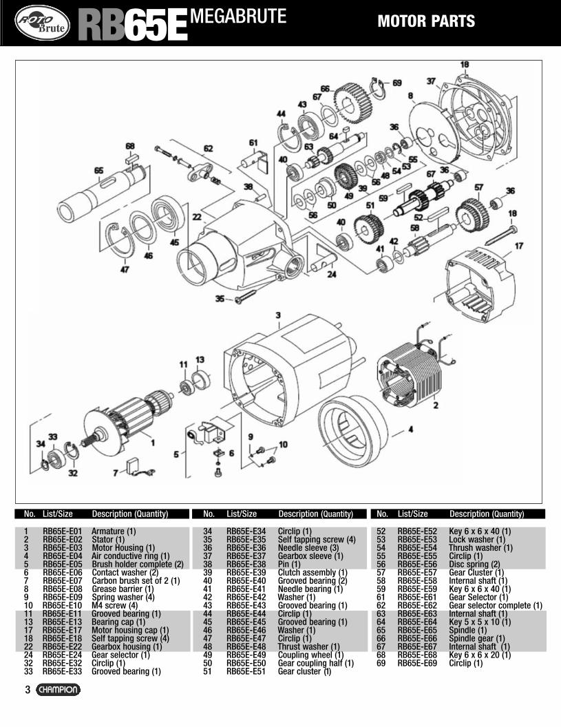
MOTOR PARTS
-
g
3
MEGABRUTE
No. List/Size Description (Quantity)
1 RB65E-E01 Armature (1)2 RB65E-E02 Stator (1)3 RB65E-E03 Motor Housing (1)4 RB65E-E04 Air conductive ring (1)5 RB65E-E05 Brush holder complete (2)6 RB65E-E06 Contact washer (2)7 RB65E-E07 Carbon brush set of 2 (1)8 RB65E-E08 Grease barrier (1)9 RB65E-E09 Spring washer (4)10 RB65E-E10 M4 screw (4)11 RB65E-E11 Grooved bearing (1)13 RB65E-E13 Bearing cap (1)17 RB65E-E17 Motor housing cap (1)18 RB65E-E18 Self tapping screw (4)22 RB65E-E22 Gearbox housing (1)24 RB65E-E24 Gear selector (1)32 RB65E-E32 Circlip (1)33 RB65E-E33 Grooved bearing (1)
No. List/Size Description (Quantity)
34 RB65E-E34 Circlip (1)35 RB65E-E35 Self tapping screw (4)36 RB65E-E36 Needle sleeve (3)37 RB65E-E37 Gearbox sleeve (1)38 RB65E-E38 Pin (1)39 RB65E-E39 Clutch assembly (1)40 RB65E-E40 Grooved bearing (2)41 RB65E-E41 Needle bearing (1)42 RB65E-E42 Washer (1)43 RB65E-E43 Grooved bearing (1)44 RB65E-E44 Circlip (1)45 RB65E-E45 Grooved bearing (1)46 RB65E-E46 Washer (1)47 RB65E-E47 Circlip (1)48 RB65E-E48 Thrust washer (1)49 RB65E-E49 Coupling wheel (1)50 RB65E-E50 Gear coupling half (1)51 RB65E-E51 Gear cluster (1)
No. List/Size Description (Quantity)
52 RB65E-E52 Key 6 x 6 x 40 (1)53 RB65E-E53 Lock washer (1)54 RB65E-E54 Thrush washer (1)55 RB65E-E55 Circlip (1)56 RB65E-E56 Disc spring (2)57 RB65E-E57 Gear Cluster (1)58 RB65E-E58 Internal shaft (1)59 RB65E-E59 Key 6 x 6 x 40 (1)61 RB65E-E61 Gear Selector (1)62 RB65E-E62 Gear selector complete (1)63 RB65E-E63 Internal shaft (1)64 RB65E-E64 Key 5 x 5 x 10 (1)65 RB65E-E65 Spindle (1)66 RB65E-E66 Spindle gear (1)67 RB65E-E67 Internal shaft (1)68 RB65E-E68 Key 6 x 6 x 20 (1)69 RB65E-E69 Circlip (1)
RB65E
RB65E:Layout 1 2/24/11 4:13 PM Page 5

RB65E STAND SCHEMATIC
N
1 2 3 4 5 6 7 1 1 1 1 1
4
MEGABRUTE
INCLUDED WITH EVERY RB65E:Carrying case, safety strap,RB634 3/4” arbor, cutting fluid,drift key and hex keys, safetyguard.
36
25
13
36
No. List/Size Description (Quantity)
1 RB601 Main Body Casting (1) 2 RB602 Magnetic Base (1) 3 RB613 Brass Guides (2) 4 RB625 Machine Rack (1) 5 RB604 Dovetail Slide (1) 6 RB65E-6051 Lower Support Casting (1) 7 RB634 #3MT to 3/4 Arbor (1) 11 RB65E-6231 Side Fixing Casting (1) 12 RB611 Safety Guard (1) 13 RB612 Retaining Bracket (1) 14 RB524 Pinion Cap (1)15 RB221 Cap Head Screw for Pinion
M5x15 (1)16 RB614 Pinion Shaft (1) 17 RB615 Handle (3)
No. List/Size Description (Quantity)
18 RB520 Handle Knob (3) 19 RB519 Cable Gland for
Power Cord (1)19A RB519A Cable Gland for
Conduit Lead (2)20 RB506 Counduit Lead (1) 21 RB503 Mains Cable (1) 23 RB617 Side Panel (1) 24 RB515 Rectifier Unit (1) 25 RB616 Switch Panel (1) 26 RB509 Stop/Start Switch (1) 27 RB513 Power Relay 110V (1) 29 RB505 Mag Switch 110V (1) 31 RB511 Fuse Holder (1) 32 RB512 2A Fuse (1)
No. List/Size Description (Quantity)
32 RB65E-624 Neon Indicator Light (1) RB65E-637 Complete Motherboard (1)
(not pictured)35 RB61325 M5x25 Screw/Nut Guide (1)
(not pictured)36 RB502 Pinion Bushings (2)
RB516 Cutting Fluid Bottle RB638 Relay Bracket 523 Clip RB65E-EIB-MOTOR Eibenstock Motor RB65-252 Panel Screws SPANNER 7/16 & 17mm Wrench Set RB-STRAP Ratchet Safety Strap RB-POUCH Tool Pouch
12
RB65E:Layout 1 2/24/11 4:13 PM Page 6
OPERATING INSTRUCTIONS
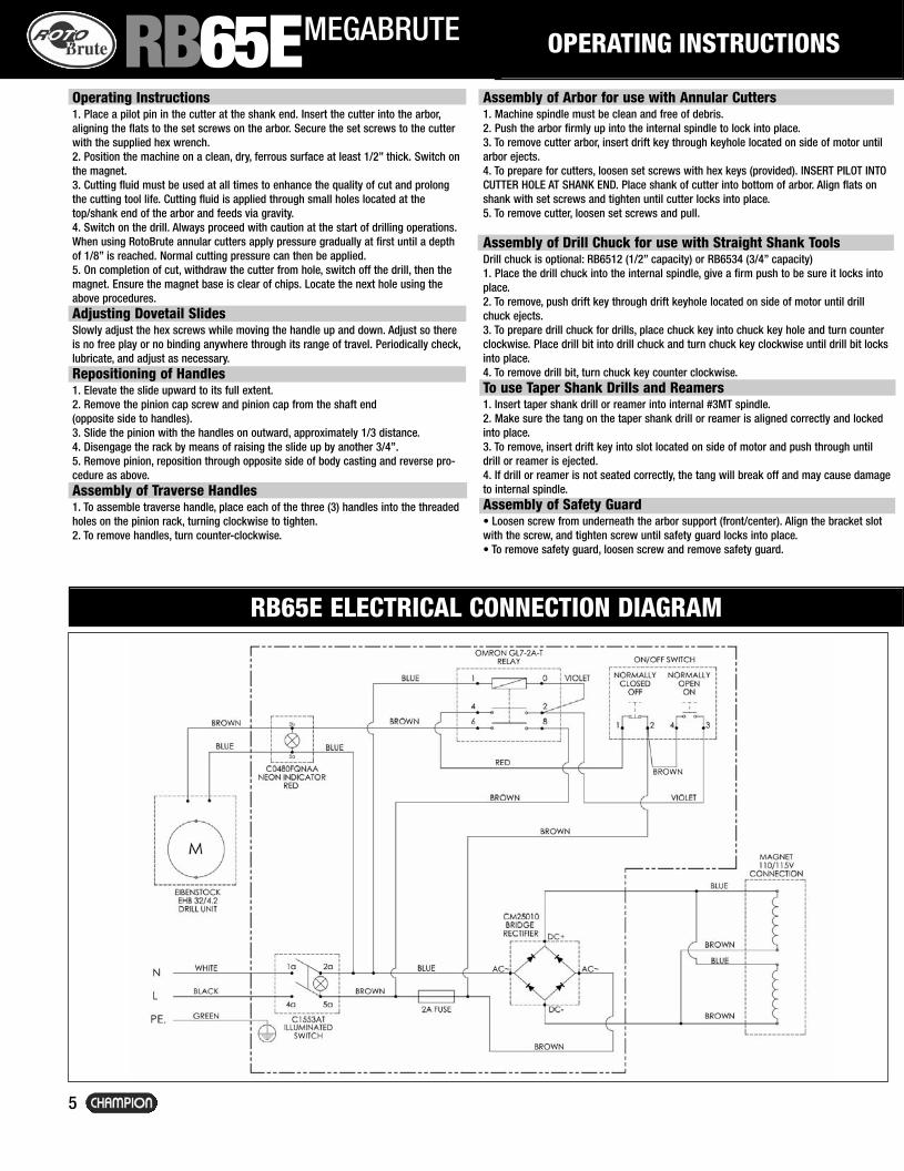
Operating Instructions1. Place a pilot pin in the cutter at the shank end. Insert the cutter into the arbor,aligning the flats to the set screws on the arbor. Secure the set screws to the cutterwith the supplied hex wrench. 2. Position the machine on a clean, dry, ferrous surface at least 1/2” thick. Switch onthe magnet. 3. Cutting fluid must be used at all times to enhance the quality of cut and prolongthe cutting tool life. Cutting fluid is applied through small holes located at thetop/shank end of the arbor and feeds via gravity.4. Switch on the drill. Always proceed with caution at the start of drilling operations. When using RotoBrute annular cutters apply pressure gradually at first until a depthof 1/8” is reached. Normal cutting pressure can then be applied. 5. On completion of cut, withdraw the cutter from hole, switch off the drill, then the magnet. Ensure the magnet base is clear of chips. Locate the next hole using theabove procedures. Adjusting Dovetail Slides Slowly adjust the hex screws while moving the handle up and down. Adjust so thereis no free play or no binding anywhere through its range of travel. Periodically check,lubricate, and adjust as necessary. Repositioning of Handles 1. Elevate the slide upward to its full extent.2. Remove the pinion cap screw and pinion cap from the shaft end(opposite side to handles). 3. Slide the pinion with the handles on outward, approximately 1/3 distance.4. Disengage the rack by means of raising the slide up by another 3/4”. 5. Remove pinion, reposition through opposite side of body casting and reverse pro-cedure as above. Assembly of Traverse Handles1. To assemble traverse handle, place each of the three (3) handles into the threadedholes on the pinion rack, turning clockwise to tighten.2. To remove handles, turn counter-clockwise.
Assembly of Arbor for use with Annular Cutters 1. Machine spindle must be clean and free of debris. 2. Push the arbor firmly up into the internal spindle to lock into place. 3. To remove cutter arbor, insert drift key through keyhole located on side of motor untilarbor ejects. 4. To prepare for cutters, loosen set screws with hex keys (provided). INSERT PILOT INTOCUTTER HOLE AT SHANK END. Place shank of cutter into bottom of arbor. Align flats onshank with set screws and tighten until cutter locks into place. 5. To remove cutter, loosen set screws and pull.
Assembly of Drill Chuck for use with Straight Shank ToolsDrill chuck is optional: RB6512 (1/2” capacity) or RB6534 (3/4” capacity)1. Place the drill chuck into the internal spindle, give a firm push to be sure it locks intoplace. 2. To remove, push drift key through drift keyhole located on side of motor until drillchuck ejects. 3. To prepare drill chuck for drills, place chuck key into chuck key hole and turn counterclockwise. Place drill bit into drill chuck and turn chuck key clockwise until drill bit locksinto place. 4. To remove drill bit, turn chuck key counter clockwise. To use Taper Shank Drills and Reamers1. Insert taper shank drill or reamer into internal #3MT spindle. 2. Make sure the tang on the taper shank drill or reamer is aligned correctly and lockedinto place. 3. To remove, insert drift key into slot located on side of motor and push through untildrill or reamer is ejected. 4. If drill or reamer is not seated correctly, the tang will break off and may cause damageto internal spindle.Assembly of Safety Guard• Loosen screw from underneath the arbor support (front/center). Align the bracket slotwith the screw, and tighten screw until safety guard locks into place. • To remove safety guard, loosen screw and remove safety guard.
RB65E ELECTRICAL CONNECTION DIAGRAM
5
MEGABRUTERB65E
RB65E:Layout 1 2/24/11 4:13 PM Page 1

P.O.Box 368, Rockville Centre, NY 11571-0368Tel: 516.536.820 Fax: 516.536.8186
www.championcuttingtool.com
il
TO
o
er ks
d
age
ot
OTHER ROTOBRUTE MACHINES AVAILABLE FROM CHAMPION
RB32 MINIBRUTE RB45 MIGHTIBRUTERB30 LITTLEBRUTE AC35
CT SeriesCarbide Tipped Annular Cutters
XL SeriesHigh Speed Annular Cutters
Annular Cutters
PORTABLE STEEL DRILLING SYSTEM
CT1501-3/8”Depth of cut
CT2002” Depth of cut
CT3003” Depth of cut
CT4004” Depth of cut
XL1001” Depth of cut
XL2002” Depth of cut
XL3003” Depth of cut
Cobalt Stack Cut2” Depth of cut
XL100T / XL200T & XL200STKHS Titanium Coated1” / 2” Depth of cut
Also Available
CT150 / CT200 / CT300 / CT400 XL100 / XL200 / XL300
© Copyright 2011 Champion Cutting Tool Corp. 03.2011 - 500
RB65E:Layout 1 2/24/11 4:13 PM Page 2