630610 & 630611 - Jegs High Performance3. adhere the brake pads into place using disc brake quiet...
13
1-800-345-4545 Jegs Performance Products www.jegs.com Note: Always refer to the vehicle owner’s manual for correct torque specifications when installing kit. Note: Always refer to the vehicle owner’s manual for correct torque specifications when installing kit. Installation Instructions 630610 & 630611 GM A,F,& X Body Rear disc brake conversion kit HIGH PERFORMANCE KIT shown. regular kit includes plain rotors and rubber brake hoses.
Transcript of 630610 & 630611 - Jegs High Performance3. adhere the brake pads into place using disc brake quiet...

1-800-345-4545 Jegs Performance Products www.jegs.com
Note: Always refer to the vehicle owner’s manual for correct torque specifi cations when installing kit.Note: Always refer to the vehicle owner’s manual for correct torque specifi cations when installing kit.
Installation Instructions
630610 & 630611GM A,F,& X Body Rear disc brake conversion kit
HIGH PERFORMANCE KIT shown. regular kit includes plain rotors and rubber brake hoses.

Part InstructionsInstallation Instructions
Page 2
Take time to read all the literature that came with this kit. Before beginning installation check the provided list of parts against what you received to
ensure that all parts are present. While this kit was designed to make the process of changing brake parts as simple as possible, NOTE: WiTh sOmE kiTs iT may BE NEcEssary TO makE miNOr chaNgEs TO yOur car! rEad all WarraNTy disclaimErs aNd rETurN pOliciEs iNcludEd iN This kiT priOr TO iNsTallaTiON!
Important
proper operation of your brakes is essential for your safety and the safety of others. any brake service should be performed ONly by persons experienced in the
installation and proper operation of brake systems. it is the responsibility of the person installing any brake component or kit to determine the suitability of the component or kit for the particular application. after installation, and before operating your vehicle, be sure to test the function of the brakes under controlled conditions. dO NOT driVE WiTh uNTEsTEd BrakEs!
Warning
always utilize safely restraints when operating the vehicle. The installation of disc brakes will require the use of 15” wheels. any attempt to install disc brake with a 14” wheel will
be the customer’s responsibility.Note
This kit is an aftermarket solution. it is not intended to be a direct installation or OEm replacement. due to changes in production in certain years, your car may require
modifications beyond these instructions for this kit to install properly.Note
CONVERTING TO FOUR WHEEL DISC BRAKES REQUIRES A DISC/DISC PROPORTIONING VALVE AND 1 1/8” BORE MASTER CYLINDER
Note
Part InstructionsInstallation Instructions
Page 3
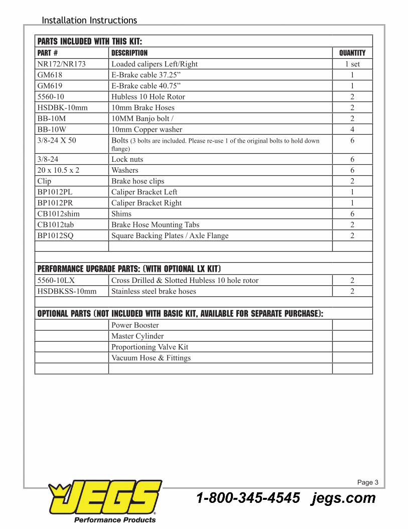
Parts included with this kit:Part # Description QuantityNr172/Nr173 loaded calipers left/right 1 setgm618 E-Brake cable 37.25” 1gm619 E-Brake cable 40.75” 15560-10 hubless 10 hole rotor 2hsdBk-10mm 10mm Brake hoses 2BB-10m 10mm Banjo bolt / 2BB-10W 10mm copper washer 43/8-24 X 50 Bolts (3 bolts are included. please re-use 1 of the original bolts to hold down
flange) 6
3/8-24 lock nuts 620 x 10.5 x 2 Washers 6clip Brake hose clips 2Bp1012pl caliper Bracket left 1Bp1012pr caliper Bracket right 1cB1012shim shims 6cB1012tab Brake hose mounting Tabs 2Bp1012sQ square Backing plates / axle Flange 2
PERFORMANCE UPGRADE PARTS: (with optional lx kit)5560-10lX cross drilled & slotted hubless 10 hole rotor 2hsdBkss-10mm stainless steel brake hoses 2
OPTIONAL PARTS (Not included with BASIC kit, available for separate purchase):power Boostermaster cylinderproportioning Valve kitVacuum hose & Fittings
Part Instructions
Page 4
Installation Instructions
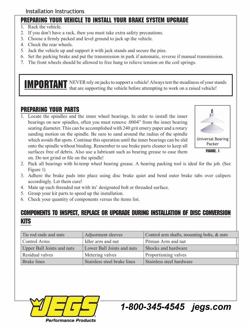
Preparing your vehicle to install your brake system upgraderack the vehicle.1. if you don’t have a rack, then you must take extra safety precautions.2. Choose a firmly packed and level ground to jack up the vehicle. 3. chock the rear wheels.4. Jack the vehicle up and support it with jack stands and secure the pins.5. set the parking brake and put the transmission in park if automatic, reverse if manual transmission.6. The front wheels should be allowed to free hang to relieve tension on the coil springs.7.
Preparing your partslocate the spindles and the inner wheel bearings. in order to install the inner 1. bearings on new spindles, often you must remove .0004” from the inner bearing seating diameter. This can be accomplished with 240 grit emery paper and a rotary sanding motion on the spindle. Be sure to sand around the radius of the spindle which avoids flat spots. Continue this operation until the inner bearings can be slid onto the spindle without binding. remember to use brake parts cleaner to keep all surfaces free of debris. also use a lubricant such as bearing grease to ease them on. Do not grind or file on the spindle!pack all bearings with hi-temp wheel bearing grease. a bearing packing tool is ideal for the job. (see 2. Figure 1) adhere the brake pads into place using disc brake quiet and bend outer brake tabs over calipers 3. accordingly. let them cure!mate up each threaded nut with its’ designated bolt or threaded surface.4. group your kit parts to speed up the installation.5. check your quantity of components versus the items list.6.
Components to inspect, replace or upgrade during installation of disc conversion kits
Tie rod ends and nuts adjustment sleeves control arm shafts, mounting bolts, & nutscontrol arms idler arm and nut pitman arm and nutupper Ball Joints and nuts lower Ball Joints and nuts shocks and hardwareresidual valves metering valves proportioning valvesBrake lines stainless steel brake lines stainless steel hardware
Universal Bearing Packer
Figure. 1
NEVEr rely on jacks to support a vehicle! always test the steadiness of your stands that are supporting the vehicle before attempting to work on a raised vehicle! Important

Part InstructionsInstallation Instructions
Page 5
Suggestions:
Take the time to identify any suspect parts that are not included in this kit. »consider making upgrades such as converting to polyurethane bushings, performance shocks, tubular a-arms, »etc. Plan any Installation (s) of replacement parts during the various stages of the drum to disc conversion process. »
Wheel bearing seal driver drum brake tool Flare wrench set Wheel chocks3/8” ratchet drive set 3/8” allen wrench or socket Jack stands Brake spring pliersBox end wrench set Ball joint fork Tire iron Brake bleeder wrenchpliers screwdriver snips grease gununiversal Bearing packer 555-W1218
line bending tool555-80086
disc brake quiet Wheel bearing grease
Ball pein hammer disc brake pad spreader tool
Brake Fluid Brake cleaner
caliper slide grease hand cleaner
InstructionsDisassembly
With the vehicle safely supported, remove the wheels.1. Remove differential cover and drain fluid. Keep bolts for 2. future use and clean gasket cover and differential of old gasket material and sealers.locate the center shaft retaining bolt and 3. carefully loosen its’ securing bolt.rotate the gear assembly towards the rear cavity area of 4. the housing to allow enough space to remove the securing bolt (figure 1).Next remove the center shaft (figure 2).5. Push the axle flange inward in order to relax the pressure on the 6. “c” clips which secure each axle located inside the differential (figure 3).Once the “c” clips are removed, remove the axle shafts. Note 7. which side they are from.Now remove the emergency brake cables by compressing the 8. compression springs and removing them from the emergency brake levers in the drum brake setup.Feed each cable out of the drum backing plates.9. Next using a brake flare wrench, not pliers, disconnect the brake 10. lines from the wheel cylinders. gently pull the brake lines away from the drum backing plate area to avoid damaging them when removing the drum brake setup.
Fig. 1
Fig. 2

Part InstructionsInstallation Instructions
Page 6
remove the drum backing plate assemblies by removing the 11. four mounting bolts (figure 4).inspect all axle seals and bearings and replace as needed.12.
Reassembly of the axle housing
Install the square axle flange. There are 6 bolts / 8 holes. 13. remember you will need to re-use one of the hold bolts to hold the flange (figure 5).re-insert the left and right axle shaft into their corresponding 14. axle tubes and secure each with the “c” clips.insert the center shaft and position it into position thereby 15. securing the spider gears and shims.Tighten the center shaft retaining bolt into the spider centering 16. shaft.check the “free spin” of the axle shafts by rotating each in 17. both directions.install the new differential cover gasket and tighten all of the 18. housing cover bolts.
Add the appropriate amount of differential fluid. Check for fluid leaks.
Caliper Bracket mount and test fit.
mount the caliper bracket provided in the kit on the inboard 19. side of the axle flanges with the pocketed side facing the axle. Feed the mounting bolts though the holes and hand tighten the nuts. make sure to have the bolt head closest to the wheels.install the rotors and secure them with 2-3 nuts to keep them 20. in position for further assembly. Be sure to mount directional rotors as intended if your kit has the directional type. (Note: Make sure rotors are seated flat on the axle. If necessary grind flange to remove burrs.install the caliper on the brackets with the bleeder screws 21. towards the top.Now check the relationship of rotor positioning in between the 22. brake pads. The kit is provided with an assortment of shims to move the caliper bracket inward to center the caliper over the rotor. use shims as needed to achieve centering (in our case we didn’t need to use shims).
Fig. 3
Fig. 4
Fig. 5
axle Flange
caliper Bracket
axle Flange caliper Bracket
shims
Part InstructionsInstallation Instructions
Page 7
Installing the rear caliper
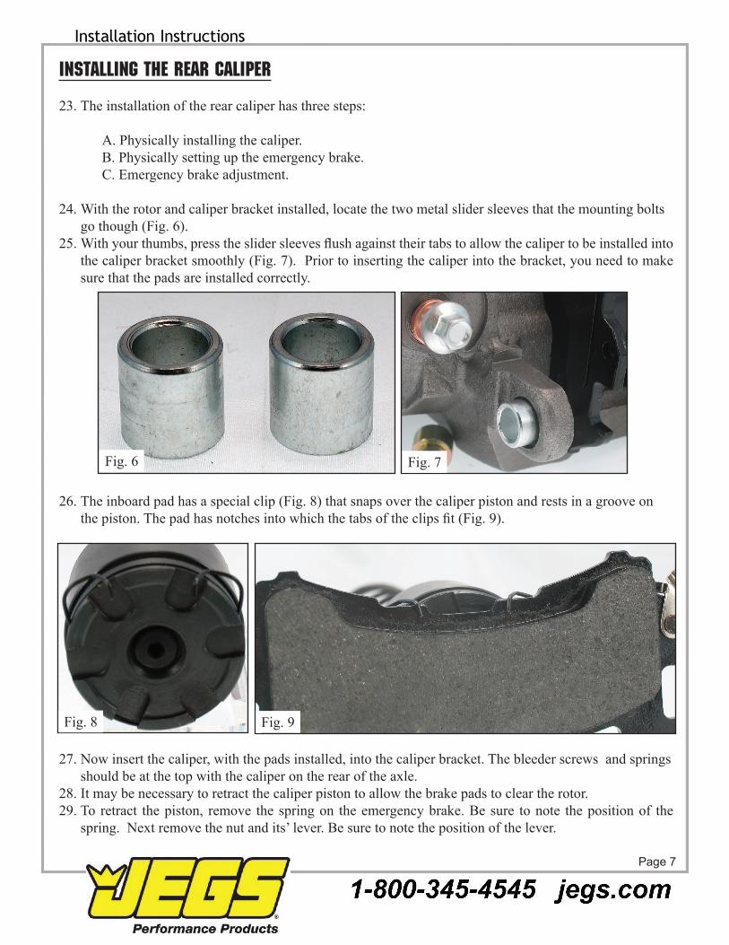
The installation of the rear caliper has three steps: 23. a. physically installing the caliper. B. physically setting up the emergency brake. c. Emergency brake adjustment.
With the rotor and caliper bracket installed, locate the two metal slider sleeves that the mounting bolts 24. go though (Fig. 6).With your thumbs, press the slider sleeves flush against their tabs to allow the caliper to be installed into 25. the caliper bracket smoothly (Fig. 7). Prior to inserting the caliper into the bracket, you need to make sure that the pads are installed correctly.
The inboard pad has a special clip (Fig. 8) that snaps over the caliper piston and rests in a groove on 26. the piston. The pad has notches into which the tabs of the clips fit (Fig. 9).
Now insert the caliper, with the pads installed, into the caliper bracket. The bleeder screws and springs 27. should be at the top with the caliper on the rear of the axle.it may be necessary to retract the caliper piston to allow the brake pads to clear the rotor.28. To retract the piston, remove the spring on the emergency brake. Be sure to note the position of the 29. spring. Next remove the nut and its’ lever. Be sure to note the position of the lever.
Fig. 7Fig. 6
Fig. 8 Fig. 9

Part InstructionsInstallation Instructions
Page 8
move the piston in or out as needed by turning the shaft 30. with the wrench positioned on the integrated hex nut. you may also use the lever to adjust piston depth.reinstall the bracket, spring, and pads. install the caliper 31. into the caliper bracket, and press the slider sleeves up against the caliper bracket and tighten down the 2 mounting bolts using an allen wrench. if needed, install the bracket shims between the axle and the caliper bracket in order to center the caliper over the rotor.Test spin the rotor, and once it is centered, tighten down 32. the bracket.proceed to setting the emergency brake.33. if you have not already done so, remove the original 34. drum brake cables from the vehicle.you will be using the front and middle sections of the 35. original drum cable setup.Next feed the end of the new cable though the spring and 36. locate, but do not install the cable into the notch on the lever yet (Fig. 10).Now take the clip provided with the kit and stake 37. it over the emergency brake cable to steady the cable against the caliper. save the old emergency brake clip so you can check the new brake clips for the proper size.With the system physically assembled, proceed 38. to the adjustment of the e brake setup.adjust the emergency brake by working the 39. lever until you can no longer spin the rotor with the lever engaged. it is a self activating mechanism.Now connect the cable to the lever on both 40. sides.Now take the brake fl ex hoses and sandwich 41. each banjo bolt end in between 2 copper crush washers and tighten onto the caliper. attach the female end of the fl ex hoses to the original hard drum lines on the axle. Be sure to secure them to the axle, but allow for axle travel up and down when in use on real road conditions. if the factory tabs are unable to fasten down the fl ex hoses then weld the included brake hose mounting tabs to the axle and use them to secure the hose.Bleed the brakes and inspect for leaks, then test the master cylinder pressure and adjustment. The 42. point is to make sure that you are not pre-loading the master cylinder and activating the rear brakes unintentionally. you are testing for basic caliper function.you may install the wheels if you like.43.
SpringE-Brake Lever
Retention Nut
Lever cranks this way to adjust piston.
Stop
Fig. 10
Part InstructionsInstallation Instructions
Page 9
connect the new emergency brake cables to the pre-existing drum cable system.44. Test the e brake by setting it from inside the car. Try to spin the wheel/rotor.45. re-adjust as necessary. The wheel must not spin.46.
NOTE: you must consistently use the emergency brake to activate the self-adjusting mechanism.
This completes the installation process. Be sure to test the brakes, re-adjust, and re-bleed prior to getting on the road.
Test brakes in slow, safe conditions. Be sure to conduct an actual “E” brake test on a reasonable incline to assure that you have it set properly. Test drive cautiously, since you may need to bleed or adjust the system again. Before operating the vehicle after installation, test the function of the brakes under controlled conditions. make several stops in a safe area. start with low speeds and gradually work up to normal speeds. dO NOT driVE WiTh uNTEsTEd BrakEs! always utilize safely restraints when operating the vehicle.
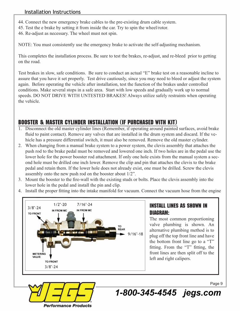
Booster & Master Cylinder Installation (if purchased with kit)disconnect the old master cylinder lines (remember, if operating around painted surfaces, avoid brake 1. fluid to paint contact). Remove any valves that are installed in the drum system and discard. If the ve-hicle has a pressure differential switch, it must also be removed. remove the old master cylinder.When changing from a manual brake system to a power system, the clevis assembly that attaches the 2. push rod to the brake pedal must be removed and lowered one inch. if two holes are in the pedal use the lower hole for the power booster rod attachment. if only one hole exists from the manual system a sec-ond hole must be drilled one inch lower. remove the clip and pin that attaches the clevis to the brake pedal and retain them. if the lower hole does not already exist, one must be drilled. screw the clevis assembly onto the new push rod on the booster about 1/2”.Mount the booster to the fire-wall with the existing studs or bolts. Place the clevis assembly into the 3. lower hole in the pedal and install the pin and clip.Install the proper fitting into the intake manifold for vacuum. Connect the vacuum hose from the engine 4.
1/2"-20 7/16"-24
9/16"-18
3/8"-24
3/8"-24
Install lines as shown in diagram:The most common proportioning valve plumbing is shown. an alternative plumbing method is to plug off the top front line and have the bottom front line go to a “T” fitting. From the “T” fitting, the front lines are then split off to the left and right calipers.

Part InstructionsInstallation Instructions
Page 10
to the power booster. yOu Will NEEd aT lEasT 18” Vacuum TO OpEraTE a BOOsTEr.Bench bleed the master cylinder with the supplied bleeder kit.5. install the master cylinder onto the booster.6. Mount the combination valve to supplied bracket and attach the bracket and lines as shown in fig. 4.7. you will now need to run two lines from the supplied combination valve to the frame. Tie the lines into 8. the existing front and rear lines with brake line couplers. you may run two separate lines from the com-bination valve to each front wheel or you may plug one outlet to the front, run one line and then split it to each front wheel.
TESTING THE PROPORTIONING VALVE for proper operation:use a test light by attaching a clip to a positive contact on the vehicle and touch the point of the tester to the 1. electrical connection of the combination valve. if the light does not come on, the valve system is operation correctly and no further testing is required.if the light does come on, this indicates that the pressure differential valve is stuck in the front or rear 2. position.Bleed the brake system to determine if the front or rear lines are blocked off. set up one front wheel and one 3. rear wheel for bleeding at the same time. crack both bleeder screws and gently pump the pedal a few times. The blocked side will trickle fluid out when the bleeder screw is cracked and the pedal pressed. An unblocked line will squirt fluid out the bleeder.The lines that are clear must be left open and the blocked lines should have the bleeder screws tight to cause 4. pressure to build up on that side. Be sure to use the standard bleeding procedures to prevent air from entering the system.slowly press the pedal with steady pressure a number of times until the light goes out; this will center the 5. differential valve. you may also hear a pop come from the proportioning valve. This is the metering valve returning to its equalized position. When the light goes out, close the bleeder screw.
WHAT TO DO IF YOU SUSPECT YOUR BOOSTER IS NOT WORKINGit is rare that one of our kits will contain a defective power booster but if you suspect that your booster is not functioning correctly perform the following tests:
BASIC TESTWith the engine off depress and release the brake pedal several times to eliminate vacuum from the power section.1. depress the pedal and hold down with light pressure, 15 to 25 pounds.2. start engine.3. if the power unit is operating the pedal will drop slightly. less pressure will be needed to hold the pedal down.4.
IF BOOSTER IS NOT OPERATING (GIVING A VERY HARD PEDAL)disconnect the vacuum hose from the booster check valve and check the vacuum level at this point with 1. the engine running with a vacuum gauge. you should have at least 18” vacuum to the booster. anything lower will begin to give a hard pedal. lf the vacuum level is below 18” you may be able to tune the engine and bring the vacuum level up to that level. if the vacuum level is around 16” the addition of a vacuum reserve canister will improve the braking. if the vacuum level is below 16” you will need to add

Part InstructionsInstallation Instructions
Page 11
an electric vacuum assist pump to supplement the engine vacuum.if the vacuum level at the check valve is 18” check that the booster check valve is working. disconnect 2. the vacuum hose at the check valve and attach a piece of tubing. Blow into the valve. if air passes through the valve is defective and must be replaced. also look into the hose attachment neck on the check valve and be sure there is no obstruction inside the valve.check your booster for a vacuum leak. With everything hooked up run the engine at moderate speed. 3. release the accelerator and turn the engine off. Wait 90 seconds and apply the brakes. if the brake applications are power assisted there is no leak. if there is no power assist the booster is defective and must be replaced.
IF THE BOOSTER IS OPERATING BUT YOU STILL HAVE A HARD PEDALYour combination valve may have tripped shutting off fluid flow to the front or rear brakes. This condition 1. will produce a very hard pedal. Check that fluid passes through the valve to both the front and rear by cracking a bleeder screw and observing a good flow of fluid. If one half of the system does hot have flow, re-center the valve.you may have frozen rear wheel cylinders or frozen caliper pistons. if these components freeze you can 2. get a very hard pedal.your pedal ratio may be too low. check your pedal ratio. The pedal ratio must be in between 4:1 to 5:1. 3. some of the older cars that had power brakes used a ratio of almost 1:1. if you add a vacuum booster to this type of car you will have a very hard pedal. Typically we are talking about late 50’s cars. adjust ratio as necessary.your booster may be undersized for the weight of the vehicle or the bore size of the master. if you try 4. to use a small diameter booster such as a 7” street rod booster for a heavy car you will get a very hard pedal. Compounding the problem is an attempt to use a large bore master (1-1/4” or larger) on a small booster.
IF YOUR BRAKE PEDAL IS VERY SENSITIVE AND THE BRAKES GRAByour pedal ratio may be too high. power brakes will require a 4:1 to 5:1 ratio. if your ratio is around 6:1 1. you are getting too much mechanical advantage making the brakes extremely sensitive. adjust the ratio to correct level.The booster may be too large for the weight of the vehicle. lightweight vehicles with large boosters give 2. you “touchy brakes”. This effect may be dampened somewhat by going to a larger bore master.Too large a booster for front drum brakes. drum brakes do not require as much pressure as disc brakes 3. (500 psi vs. 1,000 psi). If your booster is very large (11”) and you have drum brakes you are over-boosted. do a pressure test to determine what you have.The booster has a cracked internal hub. When there 4. is a crack in the phenolic hub inside the booster it will be either totally on or totally off. any slight pressure to the pedal will cause the brakes to lock up. The booster must be replaced.
Part InstructionsInstallation Instructions
Page 12
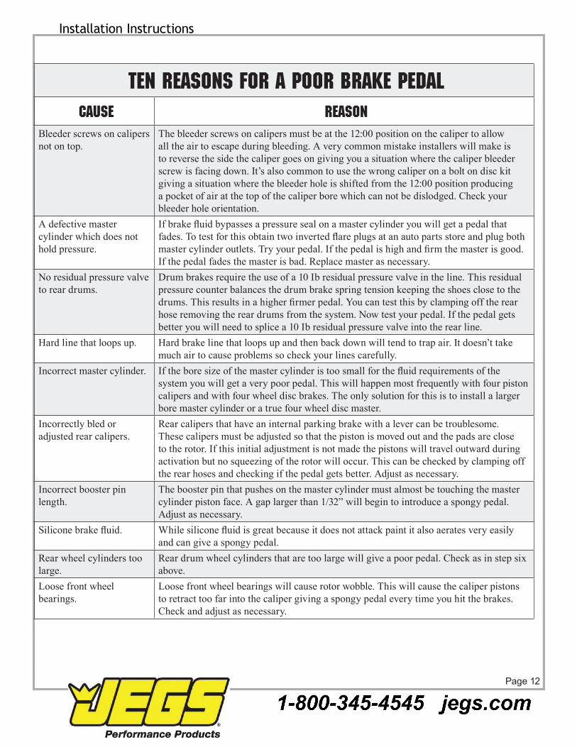
TEN REASONS FOR A POOR BRAKE PEDALCAUSE REASON
Bleeder screws on calipers not on top.
The bleeder screws on calipers must be at the 12:00 position on the caliper to allow all the air to escape during bleeding. a very common mistake installers will make is to reverse the side the caliper goes on giving you a situation where the caliper bleeder screw is facing down. it’s also common to use the wrong caliper on a bolt on disc kit giving a situation where the bleeder hole is shifted from the 12:00 position producing a pocket of air at the top of the caliper bore which can not be dislodged. check your bleeder hole orientation.
a defective master cylinder which does not hold pressure.
If brake fluid bypasses a pressure seal on a master cylinder you will get a pedal that fades. To test for this obtain two inverted flare plugs at an auto parts store and plug both master cylinder outlets. Try your pedal. If the pedal is high and firm the master is good. if the pedal fades the master is bad. replace master as necessary.
No residual pressure valve to rear drums.
drum brakes require the use of a 10 ib residual pressure valve in the line. This residual pressure counter balances the drum brake spring tension keeping the shoes close to the drums. This results in a higher firmer pedal. You can test this by clamping off the rear hose removing the rear drums from the system. Now test your pedal. if the pedal gets better you will need to splice a 10 ib residual pressure valve into the rear line.
hard line that loops up. hard brake line that loops up and then back down will tend to trap air. it doesn’t take much air to cause problems so check your lines carefully.
incorrect master cylinder. If the bore size of the master cylinder is too small for the fluid requirements of the system you will get a very poor pedal. This will happen most frequently with four piston calipers and with four wheel disc brakes. The only solution for this is to install a larger bore master cylinder or a true four wheel disc master.
incorrectly bled or adjusted rear calipers.
rear calipers that have an internal parking brake with a lever can be troublesome. These calipers must be adjusted so that the piston is moved out and the pads are close to the rotor. if this initial adjustment is not made the pistons will travel outward during activation but no squeezing of the rotor will occur. This can be checked by clamping off the rear hoses and checking if the pedal gets better. adjust as necessary.
incorrect booster pin length.
The booster pin that pushes on the master cylinder must almost be touching the master cylinder piston face. a gap larger than 1/32” will begin to introduce a spongy pedal. adjust as necessary.
Silicone brake fluid. While silicone fluid is great because it does not attack paint it also aerates very easily and can give a spongy pedal.
rear wheel cylinders too large.
rear drum wheel cylinders that are too large will give a poor pedal. check as in step six above.
loose front wheel bearings.
loose front wheel bearings will cause rotor wobble. This will cause the caliper pistons to retract too far into the caliper giving a spongy pedal every time you hit the brakes. check and adjust as necessary.

Part InstructionsInstallation Instructions
Page 13
Universal Front Disc Brake Checklistspindle properly secured to ball joints and tie rods with castle nut and cotter pin.
all mounting bolts properly tightened.
Wheel bearings properly packed with grease.
inner bearing must be installed before grease seal.
rotor i bearings slide onto spindle with ease.
Washer, castle nut properly torqued and cotter pin installed.
calipers installed and properly torqued.
Spin rotor and check for any interference. (If any interference is found, resolve problem before driving vehicle.)
Flex lines are properly installed with no interference.
Power booster (if applicable) installed properly.
master cylinder bench bled according to the instructions.
all brake lines are properly tightened and free of leaks.
Turn wheels lock to lock and check for any interference.
place wheel onto vehicle and spin the wheel to make sure there is no interference between the brakes and wheel.
Universal Rear Disc Brake Checklistall bolts on base bracket properly tightened.
all caliper mounting bolts properly tightened.
rotor slides onto axle with ease.
No interference with rotor and any other parts (splash shield, brackets, etc.).
Caliper is centered over the rotor (because of difference in axle lengths, you may have to shim caliper in or out).
No interference with caliper and rotor.
all brake lines are tight with no leaks.
parking brake is properly adjusted and not dragging, with vehicle on ground.
Adjustable proportioning valve installed (if applicable).
Distribution block modification made (if applicable).
Brake system properly bled.
WiTh EVEry NEW sET OF rOTOrs aNd pads, yOu shOuld giVE yOur VEhiclE 200 - 250 milEs OF Easy driViNg TO prOpErly sEaT ThE pads TO
ThE rOTOrs. dO NOT TakE ThE VEhiclE up TO 60 mph aNd Jam ON ThE BrakEs BEFOrE ThE FirsT 200 - 250 milE BrEak iN pEriOd is OVEr, Or yOu Will glaZE ThE pads aNd rOTOrs.
Important