6102 Scope multimeter
40
Scope Meter User’s Manual
Transcript of 6102 Scope multimeter
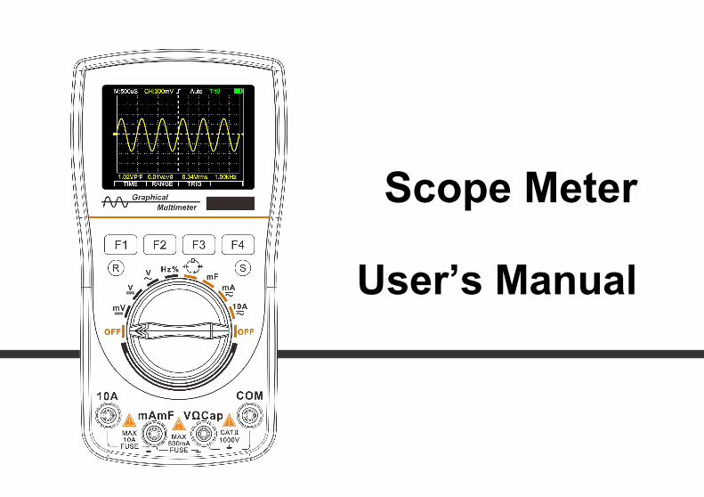
Scope Meter
User’s Manual

PrefaceDear users,
Thank you for purchasing this digital oscilloscope multimeter. We believe its innovative function combinationand humanized design will bring great convenience to your site tests. Before use, please carefully read this manual,especial the part of "Safety Instructions". Please also keep this manual property for future reference.
ContentsSAFETY INSTRUCTIONS..............................................................................................................................................1INTRODUCTION OF INSTRUMENT........................................................................................................................... 4
Main features.............................................................................................................................................................4Button functions........................................................................................................................................................5
BASIC OPERATION....................................................................................................................................................... 6Power on and off....................................................................................................................................................... 6Automatic sleep.........................................................................................................................................................6
OSCILLOSCOPE OPERATION ................................................................................................................................... 7Enter oscilloscope mode........................................................................................................................................... 7Basic display content in oscilloscope mode............................................................................................................. 7Function buttons and main option menu.................................................................................................................. 8Time base adjustment................................................................................................................................................8
Amplitude adjustment...............................................................................................................................................9Trigger control.........................................................................................................................................................10Trigger level adjustment......................................................................................................................................... 10About trigger mode................................................................................................................................................. 11About automatic waveform capture........................................................................................................................11Reminder of scanning status................................................................................................................................... 12Single scan trigger operation.................................................................................................................................. 12Holding of signal waveform................................................................................................................................... 13Storage and reading of waveform of signals.......................................................................................................... 13
THE OPERATION OF MULTIMETER........................................................................................................................15Enter multimeter mode........................................................................................................................................... 15Basic content displayed under mutlimeter mode....................................................................................................15Switching measurement function............................................................................................................................16Selection of manual/automatic measuring range....................................................................................................16Relative value measuring mode..............................................................................................................................17Peak hold (P-H) mode.............................................................................................................................................17AC and DC voltage measurement.......................................................................................................................... 19AC and DC current (400mA,10A)measurement...........................................................................................20Frequency counting and measurement of duty ratio.............................................................................................. 21Resistance measurement......................................................................................................................................... 22Diode detection....................................................................................................................................................... 23
Continuity test......................................................................................................................................................... 24Capacitor measurement...........................................................................................................................................2410mF capacitor measurement................................................................................................................................. 25The holding of measurement data...........................................................................................................................26Measurement data storage and reading...................................................................................................................26
TECHNICAL PARAMETERS AND COMPLETE SETS OF INSTRUMENTS........................................................ 28General features...................................................................................................................................................... 28Oscilloscope characteristics....................................................................................................................................28Multimeter features................................................................................................................................................. 29Display symbols and icons......................................................................................................................................30Complete sets and options of the instrument..........................................................................................................31
DAILY MAINTENANCE AND TROUBLESHOOTING............................................................................................32
1
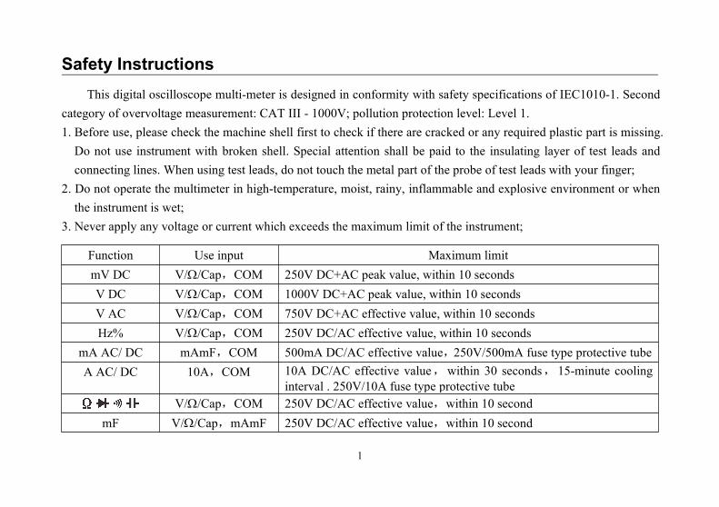
Safety InstructionsThis digital oscilloscope multi-meter is designed in conformity with safety specifications of IEC1010-1. Second
category of overvoltage measurement: CAT III - 1000V; pollution protection level: Level 1.1. Before use, please check the machine shell first to check if there are cracked or any required plastic part is missing.Do not use instrument with broken shell. Special attention shall be paid to the insulating layer of test leads andconnecting lines. When using test leads, do not touch the metal part of the probe of test leads with your finger;
2. Do not operate the multimeter in high-temperature, moist, rainy, inflammable and explosive environment or whenthe instrument is wet;
3. Never apply any voltage or current which exceeds the maximum limit of the instrument;
Function Use input Maximum limitmV DC V//Cap,COM 250V DC+AC peak value, within 10 secondsV DC V//Cap,COM 1000V DC+AC peak value, within 10 secondsV AC V//Cap,COM 750V DC+AC effective value, within 10 secondsHz% V//Cap,COM 250V DC/AC effective value, within 10 seconds
mA AC/ DC mAmF,COM 500mA DC/AC effective value,250V/500mA fuse type protective tubeA AC/ DC 10A,COM 10A DC/AC effective value,within 30 seconds,15-minute cooling
interval . 250V/10A fuse type protective tubeV//Cap,COM 250V DC/AC effective value,within 10 second
mF V//Cap,mAmF 250V DC/AC effective value,within 10 second
2
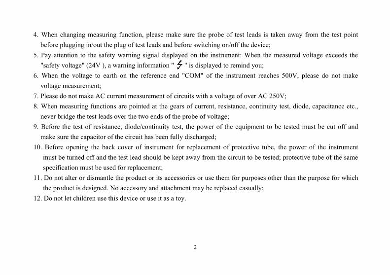
4. When changing measuring function, please make sure the probe of test leads is taken away from the test pointbefore plugging in/out the plug of test leads and before switching on/off the device;
5. Pay attention to the safety warning signal displayed on the instrument: When the measured voltage exceeds the"safety voltage" (24V ), a warning information " " is displayed to remind you;
6. When the voltage to earth on the reference end "COM" of the instrument reaches 500V, please do not makevoltage measurement;
7. Please do not make AC current measurement of circuits with a voltage of over AC 250V;8. When measuring functions are pointed at the gears of current, resistance, continuity test, diode, capacitance etc.,never bridge the test leads over the two ends of the probe of voltage;
9. Before the test of resistance, diode/continuity test, the power of the equipment to be tested must be cut off andmake sure the capacitor of the circuit has been fully discharged;
10. Before opening the back cover of instrument for replacement of protective tube, the power of the instrumentmust be turned off and the test lead should be kept away from the circuit to be tested; protective tube of the samespecification must be used for replacement;
11. Do not alter or dismantle the product or its accessories or use them for purposes other than the purpose for whichthe product is designed. No accessory and attachment may be replaced casually;
12. Do not let children use this device or use it as a toy.
3
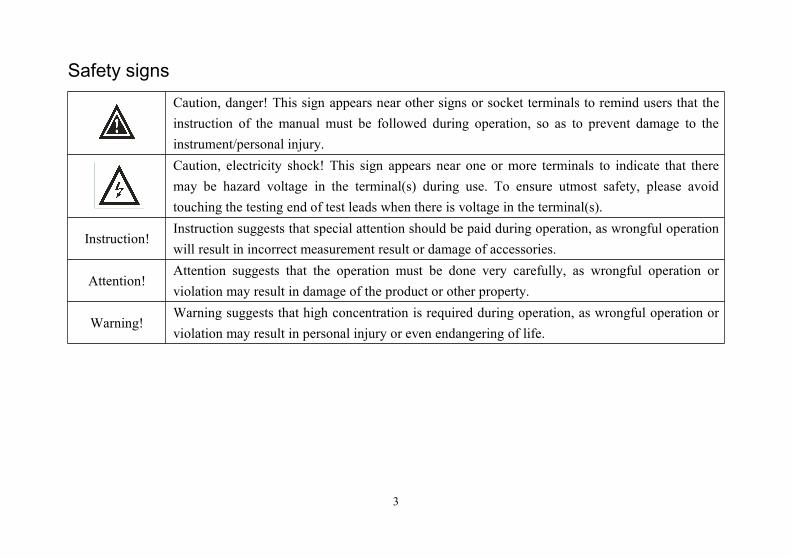
Safety signsCaution, danger! This sign appears near other signs or socket terminals to remind users that theinstruction of the manual must be followed during operation, so as to prevent damage to theinstrument/personal injury.Caution, electricity shock! This sign appears near one or more terminals to indicate that theremay be hazard voltage in the terminal(s) during use. To ensure utmost safety, please avoidtouching the testing end of test leads when there is voltage in the terminal(s).
Instruction!Instruction suggests that special attention should be paid during operation, as wrongful operationwill result in incorrect measurement result or damage of accessories.
Attention!Attention suggests that the operation must be done very carefully, as wrongful operation orviolation may result in damage of the product or other property.
Warning!Warning suggests that high concentration is required during operation, as wrongful operation orviolation may result in personal injury or even endangering of life.
4
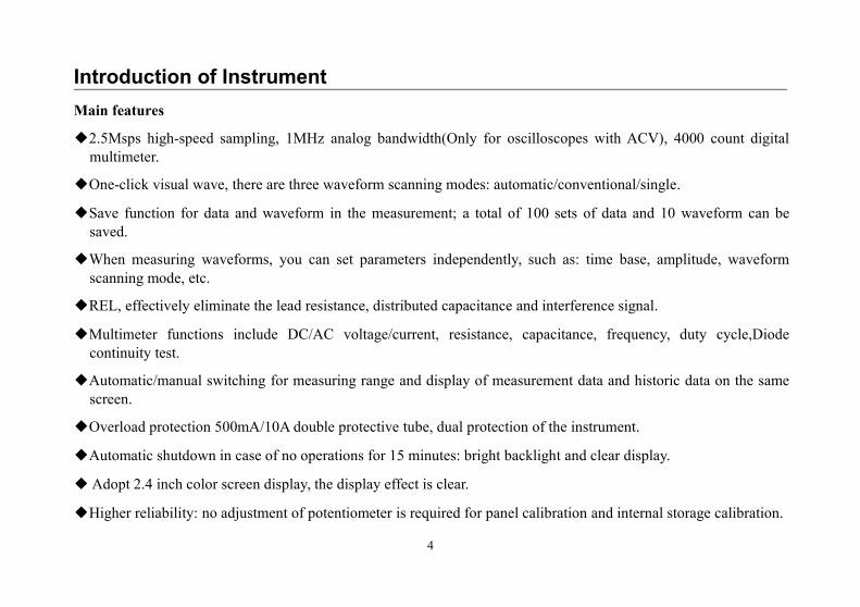
Introduction of InstrumentMain features
2.5Msps high-speed sampling, 1MHz analog bandwidth(Only for oscilloscopes with ACV), 4000 count digitalmultimeter.
One-click visual wave, there are three waveform scanning modes: automatic/conventional/single.
Save function for data and waveform in the measurement; a total of 100 sets of data and 10 waveform can besaved.
When measuring waveforms, you can set parameters independently, such as: time base, amplitude, waveformscanning mode, etc.
REL, effectively eliminate the lead resistance, distributed capacitance and interference signal.
Multimeter functions include DC/AC voltage/current, resistance, capacitance, frequency, duty cycle,Diodecontinuity test.
Automatic/manual switching for measuring range and display of measurement data and historic data on the samescreen.
Overload protection 500mA/10A double protective tube, dual protection of the instrument.
Automatic shutdown in case of no operations for 15 minutes: bright backlight and clear display.
Adopt 2.4 inch color screen display, the display effect is clear.
Higher reliability: no adjustment of potentiometer is required for panel calibration and internal storage calibration.
5
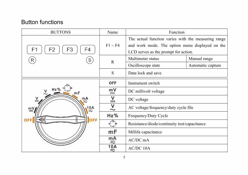
Button functionsBUTTONS Name Function
F1 ~ F4The actual function varies with the measuring rangeand work mode. The option menu displayed on theLCD serves as the prompt for action.
RMultimeter status Manual rangeOscilloscope state Automatic capture
S Data lock and save
Instrument switch
DC millivolt voltage
DC voltage
AC voltage/frequency/duty cycle file
Frequency/Duty Cycle
Resistance/diode/continuity test/capacitance
Millifa capacitance
AC/DC mA
AC/DC 10A
6
Basic operationPower on and off
Rotate the rotary knob to desired measurement gear and the power is connected to the instrument; rotate therotary knob to OFF position to turn off the power.
Attention• Be sure to move the test probe away from the test point before shutting down.• After the instrument is used, the power must be turned off in time.
Automatic sleepIf there is no operation for a set period of time, the instrument will get into automatic sleep. To turn off the
function of automatic sleep, user may press the " F1" button and then rotate the rotary knob to turn on the instrument.In this way, the instrument is set to continuous working mode.
7
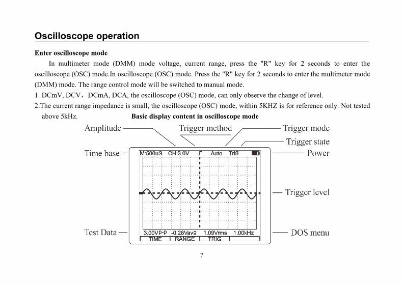
Oscilloscope operationEnter oscilloscope mode
In multimeter mode (DMM) mode voltage, current range, press the "R" key for 2 seconds to enter theoscilloscope (OSC) mode.In oscilloscope (OSC) mode. Press the "R" key for 2 seconds to enter the multimeter mode(DMM) mode. The range control mode will be switched to manual mode.1. DCmV, DCV,DCmA, DCA, the oscilloscope (OSC) mode, can only observe the change of level.2.The current range impedance is small, the oscilloscope (OSC) mode, within 5KHZ is for reference only. Not testedabove 5kHz. Basic display content in oscilloscope mode
8
Function buttons and main option menuThe function buttons of F1~F4 are located at the lower of the LCD screen. With the option menu on the screen,
these buttons will enable users to realize several functions. Some functions are provided with sub-option menu forfurther operations. Please refer to relevant later sections for the usage of these main option menu and sub-menus.
The main option menu provides the instructions for basic operations of the instrument and the details are as follows:Time base adjustment Amplitude adjustment Trigger control
TIME RANGE TRIGF1 F2 F3
1. Press the F1 key (TIME) to enter the time base adjustment sub-menu, adjust the time base and trigger position.2. Press the F2 key (RANGE) to enter the amplitude adjustment sub-menu, adjust the vertical amplitude andwaveform position.
3. Press the F3 key (TRIG) to enter the trigger control sub-menu, adjust the trigger edge/mode/level.
Time base adjustmentUnder the main menu of the oscilloscope, press the F1 key (TIME), the meter enters the time base adjustment
sub-menu:Back Time base adjustmentEXIT F1 F2 F3
1. Press the F1 key (EXIT) to exit the time base adjustment sub-menu and return to the main menu.2. Press the F2 key (), F3 key () to adjust the time base (t /div)。
9
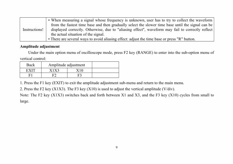
Instructions!
• When measuring a signal whose frequency is unknown, user has to try to collect the waveformfrom the fastest time base and then gradually select the slower time base until the signal can bedisplayed correctly. Otherwise, due to "aliasing effect", waveform may fail to correctly reflectthe actual situation of the signal.
• There are several ways to avoid aliasing effect: adjust the time base or press "R" button.
Amplitude adjustmentUnder the main option menu of oscilloscope mode, press F2 key (RANGE) to enter into the sub-option menu of
vertical control:Back Amplitude adjustmentEXIT X1X3 X10F1 F2 F3
1. Press the F1 key (EXIT) to exit the amplitude adjustment sub-menu and return to the main menu.2. Press the F2 key (X1X3). The F3 key (X10) is used to adjust the vertical amplitude (V/div).Note: The F2 key (X1X3) switches back and forth between X1 and X3, and the F3 key (X10) cycles from small tolarge.
10
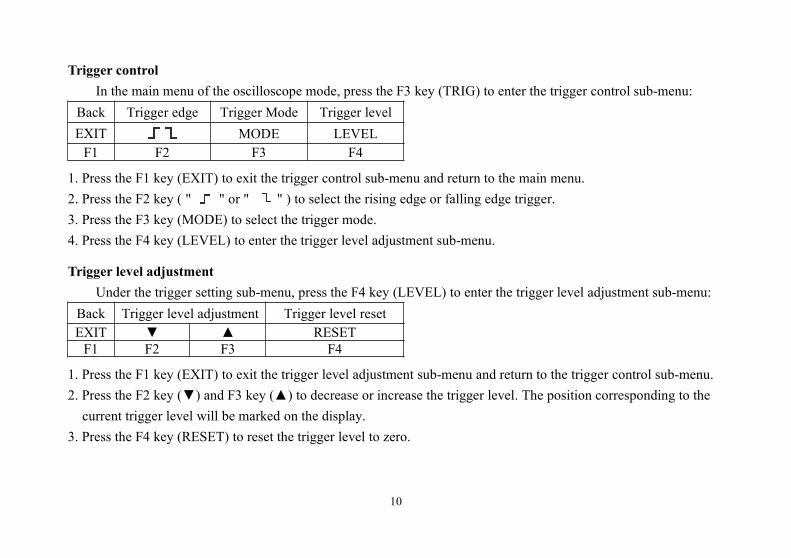
Trigger controlIn the main menu of the oscilloscope mode, press the F3 key (TRIG) to enter the trigger control sub-menu:
Back Trigger edge Trigger Mode Trigger levelEXIT MODE LEVELF1 F2 F3 F4
1. Press the F1 key (EXIT) to exit the trigger control sub-menu and return to the main menu.2. Press the F2 key ( " " or " " ) to select the rising edge or falling edge trigger.3. Press the F3 key (MODE) to select the trigger mode.4. Press the F4 key (LEVEL) to enter the trigger level adjustment sub-menu.
Trigger level adjustmentUnder the trigger setting sub-menu, press the F4 key (LEVEL) to enter the trigger level adjustment sub-menu:
Back Trigger level adjustment Trigger level resetEXIT RESETF1 F2 F3 F4
1. Press the F1 key (EXIT) to exit the trigger level adjustment sub-menu and return to the trigger control sub-menu.2. Press the F2 key () and F3 key () to decrease or increase the trigger level. The position corresponding to thecurrent trigger level will be marked on the display.
3. Press the F4 key (RESET) to reset the trigger level to zero.
11
About trigger mode
Auto : Even if no trigger condition is detected, the oscilloscope can still acquire waveforms. If there is notrigger condition, after the oscilloscope waits for a certain period of time, it will trigger itself and start collecting data.Since there is no correct trigger, the waveform displayed by the oscilloscope scrolls on the screen because it cannotbe synchronized. Once a legal trigger signal is detected, the waveform can be stabilized on the screen. Users can usethis mode to monitor low-frequency random signals or observe the amplitude of signals, such as the waveform of aDC power supply.
Normal : The waveform data is collected only after the trigger signal is detected. If no trigger occurs, theoscilloscope will not acquire a new waveform. The display content will not be refreshed.
Single : In single mode, once the trigger condition is detected, the oscilloscope starts waveform data acquisition.When new data is acquired, the latest waveform will be automatically maintained.
About automatic waveform capture1. Automatic waveform capture is only available in AC gear, and the automatic waveform capture time is about 5-15seconds.
2. Automatic waveform capture signal requirements: amplitude greater than 0.3VPP. frequency greater than: 10Hz.
12
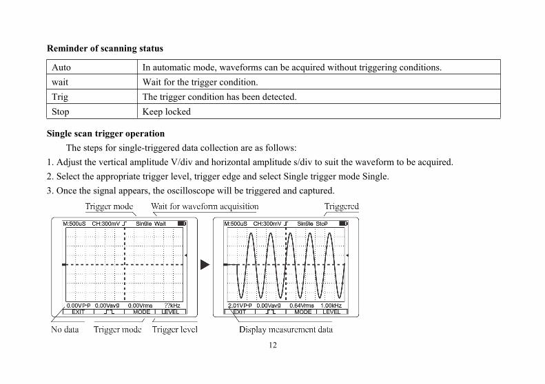
Reminder of scanning status
Auto In automatic mode, waveforms can be acquired without triggering conditions.wait Wait for the trigger condition.Trig The trigger condition has been detected.Stop Keep locked
Single scan trigger operationThe steps for single-triggered data collection are as follows:
1. Adjust the vertical amplitude V/div and horizontal amplitude s/div to suit the waveform to be acquired.2. Select the appropriate trigger level, trigger edge and select Single trigger mode Single.3. Once the signal appears, the oscilloscope will be triggered and captured.
13
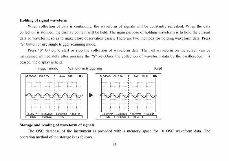
Holding of signal waveformWhen collection of data is continuing, the waveform of signals will be constantly refreshed. When the data
collection is stopped, the display content will be held. The main purpose of holding waveform is to hold the currentdata or waveform, so as to make close observation easier. There are two methods for holding waveform data: Press"S" button or use single trigger scanning mode.
Press "S" button to start or stop the collection of waveform data. The last waveform on the screen can bemaintained immediately after pressing the "S" key.Once the collection of waveform data by the oscilloscope isceased, the display is held.
Storage and reading of waveform of signalsThe OSC database of the instrument is provided with a memory space for 10 OSC waveform data. The
operation method of the storage is as follows:
14
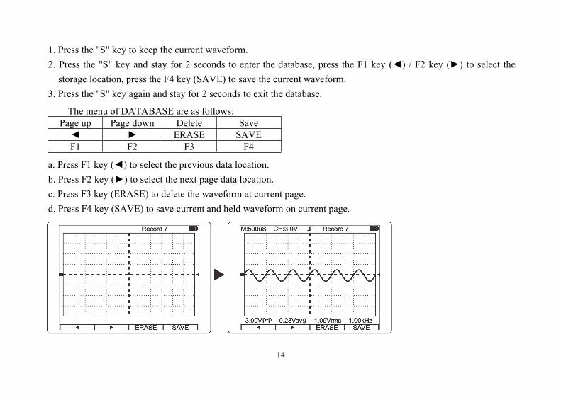
1. Press the "S" key to keep the current waveform.2. Press the "S" key and stay for 2 seconds to enter the database, press the F1 key () / F2 key () to select thestorage location, press the F4 key (SAVE) to save the current waveform.
3. Press the "S" key again and stay for 2 seconds to exit the database.
The menu of DATABASE are as follows:Page up Page down Delete Save ERASE SAVEF1 F2 F3 F4
a. Press F1 key () to select the previous data location.b. Press F2 key () to select the next page data location.c. Press F3 key (ERASE) to delete the waveform at current page.d. Press F4 key (SAVE) to save current and held waveform on current page.
15
The operation of multimeterEnter multimeter mode
Turn on the default multimeter mode (DMM) mode, or press the "R" key for a long time to switch modes.
Warning!• Please read, understand and follow the safety rules and operating methods indicated in the following.• When changing the measurement function, please be sure to remove the probe of the test lead fromthe test point first.
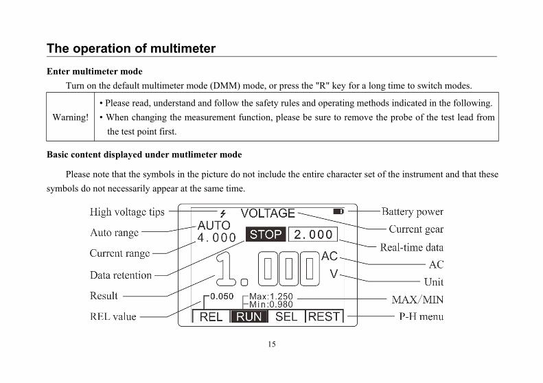
Basic content displayed under mutlimeter mode
Please note that the symbols in the picture do not include the entire character set of the instrument and that thesesymbols do not necessarily appear at the same time.
16
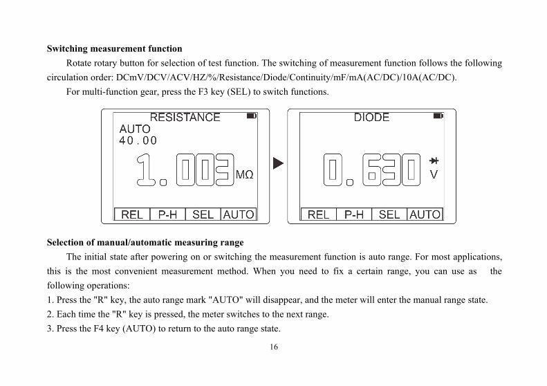
Switching measurement functionRotate rotary button for selection of test function. The switching of measurement function follows the following
circulation order: DCmV/DCV/ACV/HZ/%/Resistance/Diode/Continuity/mF/mA(AC/DC)/10A(AC/DC).For multi-function gear, press the F3 key (SEL) to switch functions.
Selection of manual/automatic measuring rangeThe initial state after powering on or switching the measurement function is auto range. For most applications,
this is the most convenient measurement method. When you need to fix a certain range, you can use as thefollowing operations:1. Press the "R" key, the auto range mark "AUTO" will disappear, and the meter will enter the manual range state.2. Each time the "R" key is pressed, the meter switches to the next range.3. Press the F4 key (AUTO) to return to the auto range state.
17
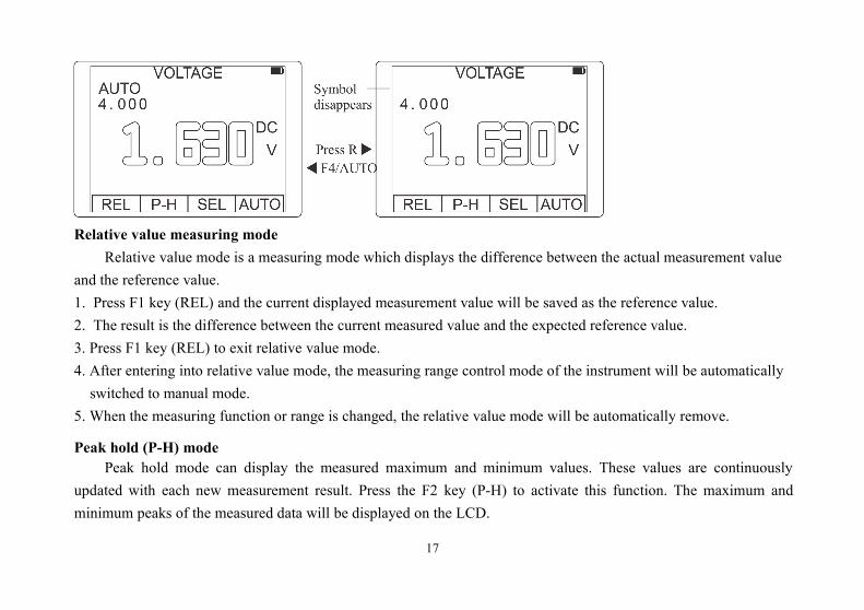
Relative value measuring modeRelative value mode is a measuring mode which displays the difference between the actual measurement value
and the reference value.1. Press F1 key (REL) and the current displayed measurement value will be saved as the reference value.2. The result is the difference between the current measured value and the expected reference value.3. Press F1 key (REL) to exit relative value mode.4. After entering into relative value mode, the measuring range control mode of the instrument will be automaticallyswitched to manual mode.
5. When the measuring function or range is changed, the relative value mode will be automatically remove.
Peak hold (P-H) modePeak hold mode can display the measured maximum and minimum values. These values are continuously
updated with each new measurement result. Press the F2 key (P-H) to activate this function. The maximum andminimum peaks of the measured data will be displayed on the LCD.
18
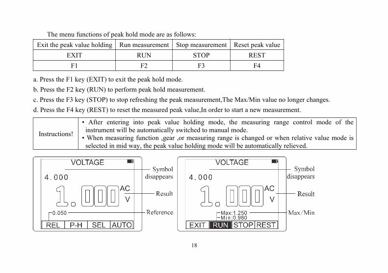
The menu functions of peak hold mode are as follows:Exit the peak value holding Run measurement Stop measurement Reset peak value
EXIT RUN STOP RESTF1 F2 F3 F4
a. Press the F1 key (EXIT) to exit the peak hold mode.b. Press the F2 key (RUN) to perform peak hold measurement.c. Press the F3 key (STOP) to stop refreshing the peak measurement,The Max/Min value no longer changes.d. Press the F4 key (REST) to reset the measured peak value,In order to start a new measurement.
Instructions!
• After entering into peak value holding mode, the measuring range control mode of theinstrument will be automatically switched to manual mode.• When measuring function ,gear ,or measuring range is changed or when relative value mode isselected in mid way, the peak value holding mode will be automatically relieved.
19
AC and DC voltage measurement
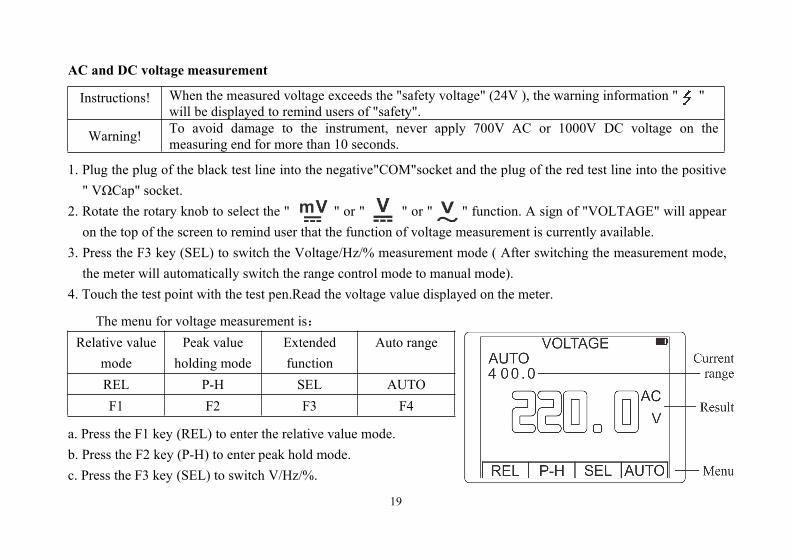
Instructions! When the measured voltage exceeds the "safety voltage" (24V ), the warning information " "will be displayed to remind users of "safety".
Warning! To avoid damage to the instrument, never apply 700V AC or 1000V DC voltage on themeasuring end for more than 10 seconds.
1. Plug the plug of the black test line into the negative"COM"socket and the plug of the red test line into the positive" VΩCap" socket.
2. Rotate the rotary knob to select the " " or " " or " " function. A sign of "VOLTAGE" will appearon the top of the screen to remind user that the function of voltage measurement is currently available.
3. Press the F3 key (SEL) to switch the Voltage/Hz/% measurement mode ( After switching the measurement mode,the meter will automatically switch the range control mode to manual mode).
4. Touch the test point with the test pen.Read the voltage value displayed on the meter.
The menu for voltage measurement is:Relative value
modePeak value
holding modeExtendedfunction
Auto range
REL P-H SEL AUTOF1 F2 F3 F4
a. Press the F1 key (REL) to enter the relative value mode.b. Press the F2 key (P-H) to enter peak hold mode.c. Press the F3 key (SEL) to switch V/Hz/%.
20
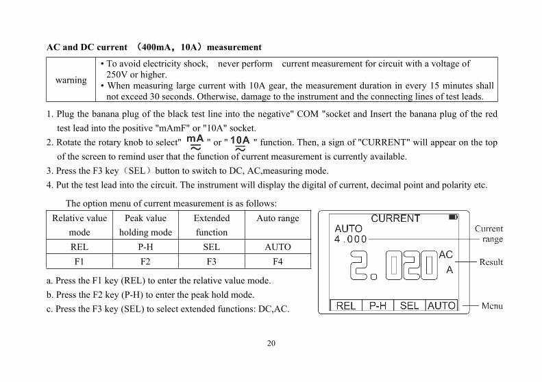
AC and DC current (400mA,10A)measurement
warning
• To avoid electricity shock, never perform current measurement for circuit with a voltage of250V or higher.
• When measuring large current with 10A gear, the measurement duration in every 15 minutes shallnot exceed 30 seconds. Otherwise, damage to the instrument and the connecting lines of test leads.
1. Plug the banana plug of the black test line into the negative" COM "socket and Insert the banana plug of the redtest lead into the positive "mAmF" or "10A" socket.
2. Rotate the rotary knob to select" " or " " function. Then, a sign of "CURRENT" will appear on the topof the screen to remind user that the function of current measurement is currently available.
3. Press the F3 key(SEL)button to switch to DC, AC,measuring mode.4. Put the test lead into the circuit. The instrument will display the digital of current, decimal point and polarity etc.
The option menu of current measurement is as follows:Relative value
modePeak value
holding modeExtendedfunction
Auto range
REL P-H SEL AUTOF1 F2 F3 F4
a. Press the F1 key (REL) to enter the relative value mode.b. Press the F2 key (P-H) to enter the peak hold mode.c. Press the F3 key (SEL) to select extended functions: DC,AC.
21
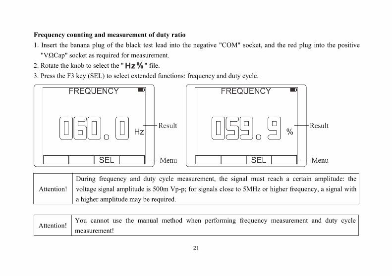
Frequency counting and measurement of duty ratio1. Insert the banana plug of the black test lead into the negative "COM" socket, and the red plug into the positive"VΩCap" socket as required for measurement.
2. Rotate the knob to select the " " file.3. Press the F3 key (SEL) to select extended functions: frequency and duty cycle.
Attention!During frequency and duty cycle measurement, the signal must reach a certain amplitude: thevoltage signal amplitude is 500m Vp-p; for signals close to 5MHz or higher frequency, a signal witha higher amplitude may be required.
Attention!You cannot use the manual method when performing frequency measurement and duty cyclemeasurement!
22
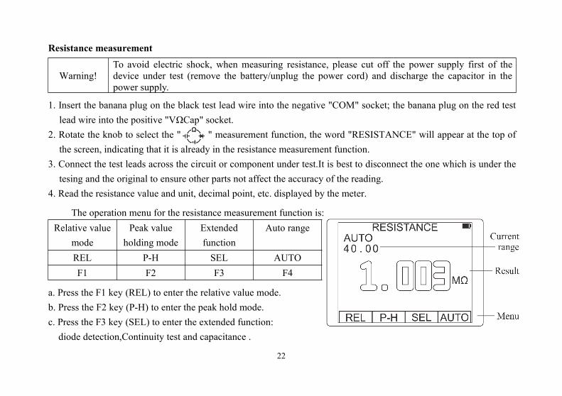
Resistance measurement
Warning!To avoid electric shock, when measuring resistance, please cut off the power supply first of thedevice under test (remove the battery/unplug the power cord) and discharge the capacitor in thepower supply.
1. Insert the banana plug on the black test lead wire into the negative "COM" socket; the banana plug on the red testlead wire into the positive "VΩCap" socket.
2. Rotate the knob to select the " " measurement function, the word "RESISTANCE" will appear at the top ofthe screen, indicating that it is already in the resistance measurement function.
3. Connect the test leads across the circuit or component under test.It is best to disconnect the one which is under thetesing and the original to ensure other parts not affect the accuracy of the reading.
4. Read the resistance value and unit, decimal point, etc. displayed by the meter.
The operation menu for the resistance measurement function is:Relative value
modePeak value
holding modeExtendedfunction
Auto range
REL P-H SEL AUTOF1 F2 F3 F4
a. Press the F1 key (REL) to enter the relative value mode.b. Press the F2 key (P-H) to enter the peak hold mode.c. Press the F3 key (SEL) to enter the extended function:diode detection,Continuity test and capacitance .
23
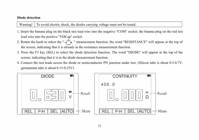
Diode detection
Warning! To avoid electric shock, the diodes carrying voltage must not be tested.
1. Insert the banana plug on the black test lead wire into the negative "COM" socket; the banana plug on the red testlead wire into the positive "VΩCap" socket.
2. Rotate the knob to select the " " measurement function, the word "RESISTANCE" will appear at the top ofthe screen, indicating that it is already in the resistance measurement function.
3. Press the F3 key (SEL) to select the diode detection function. The word "DIODE" will appear at the top of thescreen, indicating that it is in the diode measurement function.
4. Connect the test leads across the diode or semiconductor PN junction under test. (Silicon tube is about 0.5-0.7V,germanium tube is about 0.15-0.25V).
24
Continuity test
Warning! In order to avoid electric shock, the continuity test must not be carried out on the line carryingvoltage.
1. Insert the banana plug on the black test lead wire into the negative "COM" socket; the banana plug on the red testlead wire into the positive "VΩCap" socket.
2. Rotate the knob to select " " measurement function, the word "CONTINUITY" will appear at the top of thescreen, indicating that it is in the resistance measurement function.
3. Press the F3 key (SEL) to select the continuity test function.4. Touch the circuit under test with a test lead. If the resistance is less than 50Ω, the buzzer will sound.
Capacitance measurement
Warning! In order to avoid electric shock, the capacitor carrying voltage shall not be tested.
1. Insert the banana plug on the black test lead cable into the negative "COM" socket; the banana plug on the red testlead cable into the positive "VΩCap" socket.
2. Rotate the knob to select " " measurement function, the word "RESISTANCE" will appear at the top of thescreen, indicating that it is already in the resistance measurement function.
3. Press the F3 key (SEL) to select the capacitance measurement function. The word "CAPACITANCE" will appearat the top of the screen, indicating that it is already in the capacitance measurement function.
4. Touch the test pen to the measured capacitance, and read the capacitance, decimal point and unit.
Warning! Capacitance/mF capacitance measurement function cannot use manual range!
25
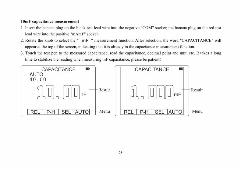
10mF capacitance measurement1. Insert the banana plug on the black test lead wire into the negative "COM" socket; the banana plug on the red testlead wire into the positive "mAmF" socket.
2. Rotate the knob to select the " " measurement function. After selection, the word "CAPACITANCE" willappear at the top of the screen, indicating that it is already in the capacitance measurement function.
3. Touch the test pen to the measured capacitance, read the capacitance, decimal point and unit, etc. It takes a longtime to stabilize the reading when measuring mF capacitance, please be patient!
26
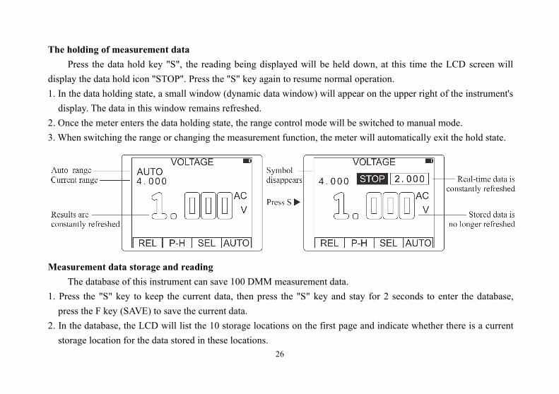
The holding of measurement dataPress the data hold key "S", the reading being displayed will be held down, at this time the LCD screen will
display the data hold icon "STOP". Press the "S" key again to resume normal operation.1. In the data holding state, a small window (dynamic data window) will appear on the upper right of the instrument'sdisplay. The data in this window remains refreshed.
2. Once the meter enters the data holding state, the range control mode will be switched to manual mode.3. When switching the range or changing the measurement function, the meter will automatically exit the hold state.
Measurement data storage and readingThe database of this instrument can save 100 DMM measurement data.
1. Press the "S" key to keep the current data, then press the "S" key and stay for 2 seconds to enter the database,press the F key (SAVE) to save the current data.
2. In the database, the LCD will list the 10 storage locations on the first page and indicate whether there is a currentstorage location for the data stored in these locations.
27
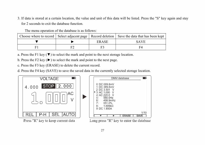
3. If data is stored at a certain location, the value and unit of this data will be listed. Press the "S" key again and stayfor 2 seconds to exit the database function.
The menu operation of the database is as follows:Choose where to record Select adjacent page Record deletion Save the data that has been kept
ERASE SAVEF1 F2 F3 F4
a. Press the F1 key () to select the mark and point to the next storage location.b. Press the F2 key () to select the mark and point to the next page.c. Press the F3 key (ERASE) to delete the current record.d. Press the F4 key (SAVE) to save the saved data in the currently selected storage location.
28
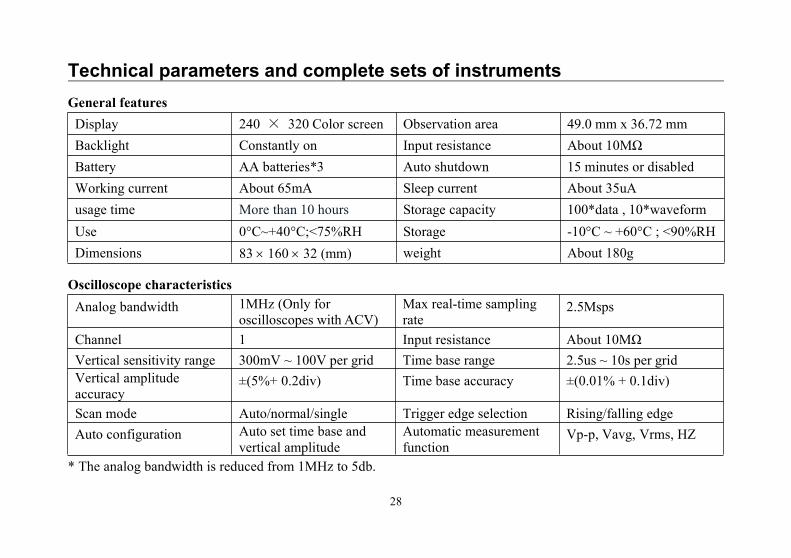
Technical parameters and complete sets of instrumentsGeneral featuresDisplay 240 × 320 Color screen Observation area 49.0 mm x 36.72 mmBacklight Constantly on Input resistance About 10MΩBattery AA batteries*3 Auto shutdown 15 minutes or disabledWorking current About 65mA Sleep current About 35uAusage time More than 10 hours Storage capacity 100*data , 10*waveformUse 0°C~+40°C;<75%RH Storage -10°C ~ +60°C ; <90%RHDimensions 83 160 32 (mm) weight About 180g
Oscilloscope characteristicsAnalog bandwidth 1MHz (Only for
oscilloscopes with ACV)Max real-time samplingrate
2.5Msps
Channel 1 Input resistance About 10MΩVertical sensitivity range 300mV ~ 100V per grid Time base range 2.5us ~ 10s per gridVertical amplitudeaccuracy
±(5%+ 0.2div) Time base accuracy ±(0.01% + 0.1div)
Scan mode Auto/normal/single Trigger edge selection Rising/falling edgeAuto configuration Auto set time base and
vertical amplitudeAutomatic measurementfunction
Vp-p, Vavg, Vrms, HZ
* The analog bandwidth is reduced from 1MHz to 5db.
29
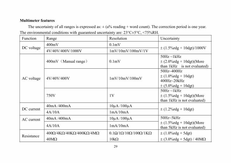
Multimeter featuresThe uncertainty of all ranges is expressed as: ± (a% reading + word count). The correction period is one year.
The environmental conditions with guaranteed uncertainty are: 23°C±5°C, <75%RH.Function Range Resolution Uncertainty
DC voltage400mV 0.1mV
(1.5%rdg + 10dgt)/1000V4V/40V/400V/1000V 1mV/10mV/100mV/1V
AC voltage
400mV(Manual range) 0.1mV50Hz ~1kHz (2.0%rdg + 10dgt)(Morethan 1kHz is not evaluated)
4V/40V/400V 1mV/10mV/100mV
50Hz~400Hz (1.0%rdg + 10dgt)400Hz~20kHz (5.0%rdg + 10dgt)
750V 1V50Hz ~1kHz (1.5%rdg + 10dgt)(Morethan 1kHz is not evaluated)
DC current40mA /400mA 10µA /100µA
(1.2%rdg + 10dgt)4A/10A 1mA/10mA
AC current 40mA /400mA 10µA /100µA 50Hz~5kHz (1.5%rdg + 10dgt)(Morethan 5kHz is not evaluated)4A/10A 1mA/10mA
Resistance400/4K/40K/400K/4M40M
0.1Ω/1/10/100/1K10k
(1.0%rdg + 5dgt) (3.0%rdg + 5dgt) / 40M
30
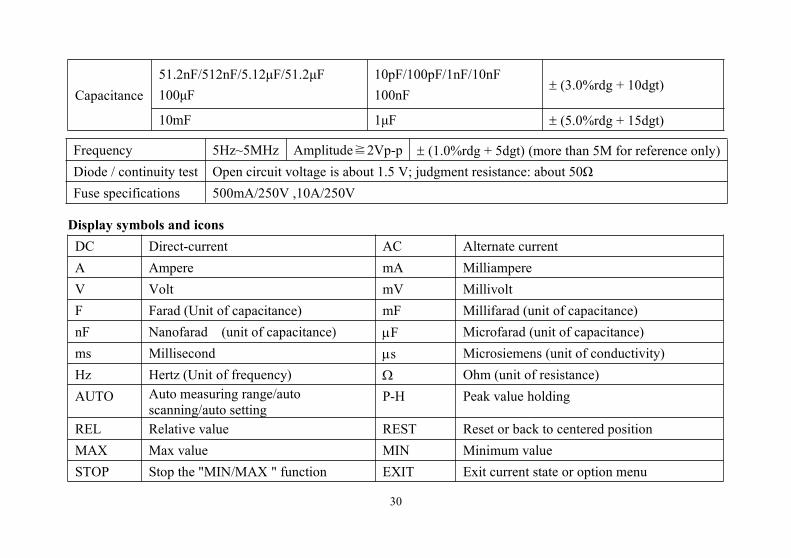
Capacitance51.2nF/512nF/5.12μF/51.2μF100μF
10pF/100pF/1nF/10nF100nF
(3.0%rdg + 10dgt)
10mF 1μF (5.0%rdg + 15dgt)
Display symbols and iconsDC Direct-current AC Alternate currentA Ampere mA MilliampereV Volt mV MillivoltF Farad (Unit of capacitance) mF Millifarad (unit of capacitance)nF Nanofarad (unit of capacitance) F Microfarad (unit of capacitance)ms Millisecond s Microsiemens (unit of conductivity)Hz Hertz (Unit of frequency) Ohm (unit of resistance)AUTO Auto measuring range/auto
scanning/auto settingP-H Peak value holding
REL Relative value REST Reset or back to centered positionMAX Max value MIN Minimum valueSTOP Stop the "MIN/MAX " function EXIT Exit current state or option menu
Frequency 5Hz~5MHz Amplitude≧2Vp-p (1.0%rdg + 5dgt) (more than 5M for reference only)Diode / continuity test Open circuit voltage is about 1.5 V; judgment resistance: about 50ΩFuse specifications 500mA/250V ,10A/250V
31
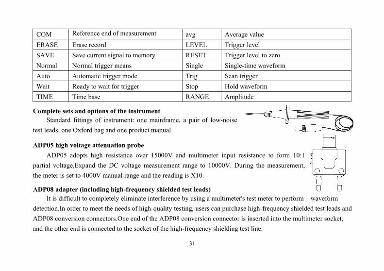
COM Reference end of measurement avg Average valueERASE Erase record LEVEL Trigger levelSAVE Save current signal to memory RESET Trigger level to zeroNormal Normal trigger means Single Single-time waveformAuto Automatic trigger mode Trig Scan triggerWait Ready to wait for trigger Stop Hold waveformTIME Time base RANGE Amplitude
Complete sets and options of the instrumentStandard fittings of instrument: one mainframe, a pair of low-noise
test leads, one Oxford bag and one product manual
ADP05 high voltage attenuation probeADP05 adopts high resistance over 15000V and multimeter input resistance to form 10:1
partial voltage,Expand the DC voltage measurement range to 10000V. During the measurement,the meter is set to 4000V manual range and the reading is X10.
ADP08 adapter (including high-frequency shielded test leads)It is difficult to completely eliminate interference by using a multimeter's test meter to perform waveform
detection.In order to meet the needs of high-quality testing, users can purchase high-frequency shielded test leads andADP08 conversion connectors.One end of the ADP08 conversion connector is inserted into the multimeter socket,and the other end is connected to the socket of the high-frequency shielding test line.
32
Daily maintenance and troubleshootingKeep the instrument dryIf the instrument is wet, please wipe it until it’s dry. If you are not sure whether it’s dry, please do not use it .
Please store and use the instrument in ambient temperatureExtreme ambient temperature will reduce the service life of electric components, deform plastic parts or even causenon-availability for use of the instrument.
Handle the instrument carefullyFall may cause damage to liquid crystal display, electric components or shell.
Keep the instrument cleanUse a piece of wet cloth dipped with a little of detergent to wipe the shell of the instrument often. Do not use roughobjects, chemical solutions or alcohol etc.
Replacement of protective tube1. Remove the probe from test point and shut down the power.2. Loosen the fixing screw and take off the back cover. The protective tube is at the back side of the test socket.3. Take out the burnt protective tube and replace it with a new one of the same specification: for 500mA current, the500mA /250V fuse type protective tube is used; for 10A current, the 10A/250V fuse type protective tube is used.Put back the back cover and fixed it with screws.
33
Repair and maintenance of the instrument1. This is a precision instrument. Without the authorization of the products center of the company, please do not alterany circuit, replace any component or perform any calibration or repair of the product.
2. All test leads, accessories or optional fittings of the instrument cannot be replaced, repaired or substitutedrandomly.
Warning!Before opening the battery back cover, be sure to disconnect the probe from any voltage source. Donot use the instrument until the cover is closed and fixed.
TroubleshootingIf your instrument fails, you may wish to check it yourself as follows before you determine that the instrument mustbe repaired.
No display on screen, no response from buttons1. If there is no power supply, please make sure that the battery in the device is not exhausted and the battery andbattery slice are intact and correctly connected.
2. Turn the knob to the shutdown position and then to the measurement position.
Not measurablePlease check the goodness of the test leads (the test leads are short-circuited on and off).
Current cannot be measuredThe fuse is blown. You should replace the fuse.
34
Replacement batteryWhen the LCD display shows a red " " prompt, the battery should be replaced in time (battery specification:AA1.5Vx3), otherwise the measurement accuracy may be affected.Steps:1. Remove the test leads and set the position to "OFF"; open the battery cover and take out the old battery (take themiddle battery first).
2. Replace 3 new batteries (battery specifications: AA1.5Vx3), install the batteries on both sides, and restore thebattery cover.
3. When not using for a long time, the battery should be taken out. To prevent battery leakage from damaging a pack.
Note:The contents of the manual are subject to change without notice.


![Whirlpool Delta Awm 6102 [ET]](https://static.fdocuments.us/doc/165x107/540884fcdab5cac8598b4a9b/whirlpool-delta-awm-6102-et.jpg)