602.03 602-1 SECTION 602 - REINFORCING STEEL 1 2 3 602.01 ...
22
602.03 602-1 SECTION 602 - REINFORCING STEEL 1 2 3 602.01 Description. This section describes furnishing, storing, and placing 4 reinforcing steel (also referred to as rebar, bar, or reinforcement). 5 6 602.02 Materials. 7 8 Reinforcing Steel 709.01 9 10 Submit certificate of compliance for reinforcing steel. When steel bars, other 11 than bars conforming to ASTM A 706, are to be spliced by welding, or when 12 requested by the Engineer, submit six copies of certified mill test reports showing 13 physical and chemical analyses for each heat and size of reinforcing steel. 14 15 602.03 Construction. 16 17 (A) Order Lists and Bending Diagrams. Submit six copies of reinforcing 18 steel order lists and bending diagrams to the Engineer prior to fabrication. 19 Assume absolute responsibility for accuracy of lists and diagrams. 20 21 (B) Storage, Surface Condition, and Protection of Reinforcement. 22 Store reinforcing steel above ground surface on platforms, skids, or other 23 supports. Protect reinforcing steel from mechanical damage and surface 24 deterioration caused by exposure to corrosion-producing conditions. When 25 placed in the work, reinforcing steel shall be free from dirt, loose rust or 26 scale, mortar, paint, grease, oil, or other coatings that would destroy or 27 reduce bond. Reinforcing steel shall be free from injurious defects such as 28 cracks and laminations. Bonded rust, surface seams, surface irregularities, 29 or mill scale shall not be cause for rejection, provided minimum dimensions, 30 cross-sectional area, and tensile properties of a hand-wire-brushed specimen 31 meet physical requirements for size and grade of steel specified. 32 33 (C) Fabrication. 34 35 (1) Bending. Bend reinforcing steel cold. Do not field bend bars 36 that are partially embedded in concrete, except as indicated in the 37 contract documents or permitted by the Engineer. 38 39 Bend or straighten bars in a manner that shall not damage the 40 material. Bars having cracks or splits at bends will be rejected. 41 Unless otherwise indicated in the contract documents, bend steel only 42 once at the same location. 43 44 (2) Hooks and Bend Dimensions. Dimensions of hooks and 45 diameters of bends shall be in accordance with the contract 46 documents. When dimensions of hooks or diameter of bends are not 47 indicated in the contract documents, they shall conform to AASHTO 48
Transcript of 602.03 602-1 SECTION 602 - REINFORCING STEEL 1 2 3 602.01 ...
602.03
602-1
SECTION 602 - REINFORCING STEEL 1 2 3 602.01 Description. This section describes furnishing, storing, and placing 4 reinforcing steel (also referred to as rebar, bar, or reinforcement). 5 6 602.02 Materials. 7 8 Reinforcing Steel 709.01 9 10
Submit certificate of compliance for reinforcing steel. When steel bars, other 11 than bars conforming to ASTM A 706, are to be spliced by welding, or when 12 requested by the Engineer, submit six copies of certified mill test reports showing 13 physical and chemical analyses for each heat and size of reinforcing steel. 14 15 602.03 Construction. 16 17
(A) Order Lists and Bending Diagrams. Submit six copies of reinforcing 18 steel order lists and bending diagrams to the Engineer prior to fabrication. 19 Assume absolute responsibility for accuracy of lists and diagrams. 20
21 (B) Storage, Surface Condition, and Protection of Reinforcement. 22 Store reinforcing steel above ground surface on platforms, skids, or other 23 supports. Protect reinforcing steel from mechanical damage and surface 24 deterioration caused by exposure to corrosion-producing conditions. When 25 placed in the work, reinforcing steel shall be free from dirt, loose rust or 26 scale, mortar, paint, grease, oil, or other coatings that would destroy or 27 reduce bond. Reinforcing steel shall be free from injurious defects such as 28 cracks and laminations. Bonded rust, surface seams, surface irregularities, 29 or mill scale shall not be cause for rejection, provided minimum dimensions, 30 cross-sectional area, and tensile properties of a hand-wire-brushed specimen 31 meet physical requirements for size and grade of steel specified. 32
33 (C) Fabrication. 34 35
(1) Bending. Bend reinforcing steel cold. Do not field bend bars 36 that are partially embedded in concrete, except as indicated in the 37 contract documents or permitted by the Engineer. 38 39
Bend or straighten bars in a manner that shall not damage the 40 material. Bars having cracks or splits at bends will be rejected. 41 Unless otherwise indicated in the contract documents, bend steel only 42 once at the same location. 43
44 (2) Hooks and Bend Dimensions. Dimensions of hooks and 45 diameters of bends shall be in accordance with the contract 46 documents. When dimensions of hooks or diameter of bends are not 47 indicated in the contract documents, they shall conform to AASHTO 48

602.03
602-2
LRFD Bridge Design Specifications, Second Edition, Article 5.10.2 – 49 Hooks and Bends. 50 51 (3) Identification. Ship reinforcing steel in standard bundles. Tag 52 bundles of reinforcing bars showing quantity, grade, size, and 53 identification that allows for checking, sorting, and placing. Tag 54 bundles of welded wire fabric reinforcement showing quantity, style 55 designation, width, and length. 56
57 (D) Placing and Fastening. Place and fasten reinforcing steel bars in 58 accordance with recommended practices and procedures in CRSI Placing 59 Reinforcing Bars. Accurately place reinforcing steel and hold firmly in 60 position indicated in the contract documents by wiring at intersections and 61 splices; and by using bar supports accepted by the Engineer that have 62 sufficient strength to resist crushing under applied loads. Unless otherwise 63 indicated in the contract documents, place reinforcing steel within tolerances 64 conforming to Table 602.03-1 – Placement Tolerances. Begin concrete 65 placement only after the Engineer inspects and accepts reinforcing steel 66 position. 67
68

602.03
602-3
68 TABLE 602.03-1 - PLACEMENT TOLERANCES
Clear distance to side forms and resulting concrete surfaces and clear distance to formed and resulting concrete soffits in direction of tolerance: Members size 4 inches or less......................... ......................................................................... Member size over 4 inches but not over 12 inches ......................................................... Member size over 12 inches but not over 2 feet Member size over 2 feet...................................
+ 1/4 inch - 3/8 inch
± 3/8 inch ± 1//2 inch ± 1 inch
Concrete cover measured perpendicular to concrete surface in direction of tolerance:1,2 Member size 12 inches or less......................... Member size over 12 inches ............................
- 3/8 inch - 1/2 inch
Distance between unbundled bars (providing that distance between reinforcement shall not be less than the greater of db or 1 inch)3 Distance between bundled bars: 2 bar bundles ................................................... 3 bar bundles ................................................... 4 bar bundles ...................................................
One-quarter specified distance not to exceed 1
inch
Not less than the greater of 1 inch or
1.4db 1.7db 2db
Spacing of non-prestressed reinforcement, deviation from specified location:4 Slabs and walls other than stirrups and ties..... Stirrups............................................................. Ties ..................................................................
± 3 inches Beam depth in
inches/12 X 1 inch Least width of
column in inches/12 X 1 inch
Longitudinal location of bends and ends of bars: At discontinuous ends of brackets and corbels At discontinuous ends of other members ......... At other locations .............................................
± 1/2 inch ± 1 inch
± 2 inches
Embedded length of bars and length of bar laps: No. 3 through No. 11........................................ No. 14 and No. 18 bar sizes (embedment only)
- 1 inch
- 2 inches Notes: 1 Reduction in cover shall not exceed one-third specified concrete cover.2 Reduction in cover to formed soffits shall not exceed 1/4 inch. 3 db = Diameter of individual bar 4 Total number of bars shall not be less than that specified.

602.03
602-4
69 Maintain proper clearance between reinforcing steel and boundaries of 70
concrete by precast concrete bar supports of equal compressive strength as 71 concrete to be placed around them, and of shape and dimensions accepted 72 by the Engineer. 73
74 Unless otherwise indicated in the contract documents, bar supports 75
and their spacing shall conform to recommendations in Chapter 3 – Bar 76 Supports of CRSI Manual of Standard Practice (MOSP). Steel wire bar 77 supports shall be Class 1 (plastic-protected) bar supports, as described in 78 CRSI MOSP. All-plastic bar supports will be allowed for vertical construction 79 only. 80
81 Separate bar layers using precast concrete blocks or other bar 82
supports accepted by the Engineer. Use of pebbles, pieces of broken stone 83 or brick, metal pipes, or wooden blocks will not be allowed. 84
85 Maintain minimum 2-1/2 bar diameters for center-to-center spacing of 86
parallel bars. Minimum clear distance between bundles of bars and adjacent 87 bundles or single bars shall be not less than the following: bundles of two 88 bars, 2 times diameter of larger bar; bundles of three bars, 2-1/2 times 89 diameter of largest bar; bundles of four bars, 3 times diameter of largest bar. 90
91 In no case shall clear distance between bars or bundles of bars be 92
less than 1-1/2 times maximum coarse aggregate size or less than 1-1/2 93 inches, whichever is greater. 94
95 Except in decks where parallel reinforcing steel is placed in two or 96
more layers, with clear distance between layers not exceeding 6 inches, 97 place bars in upper layers directly above those in bottom layer, and maintain 98 clear distance between layers of not less than 1 inch or the nominal bar 99 diameter, whichever is greater. 100
101 Tie bundled bars together at a distance of not more than 6 feet on 102
centers along length of bar. Limit maximum number of bars in bundle to two 103 bars for No. 14 and No. 18 bars and four bars for other sizes. Bundling bars 104 by tack welding will not be allowed. 105
106 Individual bars in bundle that are cut off within span of member shall 107
be terminated at different points, with at least a 40-bar diameter stagger. 108 109 Unless otherwise indicated in the contract documents, concrete cover 110
for unprotected main reinforcing steel shall conform to Table 602.03-2 - 111 Concrete Cover (Main Bars). Cover for rebar mechanical connections shall 112 be same as for reinforcing steel. 113
114

602.03
602-5
114 Cover to ties and stirrups may be 1/2 inch less than values specified in 115
Table 602.03-2 – Concrete Cover (Main Bars) but shall not be less than 1 116 inch. 117
118 TABLE 602.03-2 - CONCRETE COVER (MAIN BARS)
Exposure Condition Cover (Inches) Direct exposure to salt or brackish water 4
Cast against and permanently exposed to earth 3
Exterior (exposed to earth or weather): 2
Interior (not exposed to weather or in contact with ground): Up to No. 11 bar No. 14 and No. 18 bars
1-1/2 2
Precast soffit form panels 3/4
Precast reinforced piles Noncorrosive environments Corrosive environments1
2 3
Precast prestressed piles 2
Cast-in-place piles: Noncorrosive environments Corrosive environments2 Shells Auger-cast, tremie concrete, or slurry construction
2 3 2 3
Notes: 1 Environments where concrete will be exposed to external sources of
chlorides in service, such as brackish water, seawater, or spray from these sources.
119 (E) Splicing of Bars. 120 121
(1) General. Furnish reinforcing steel in full lengths in accordance 122 with the contract, except in the following cases: 123
124 (a) Unless otherwise indicated in the contract documents, 125 when required lengths of bars No. 4 through No. 11 are longer 126 than 40 feet, bars may be spliced by lapping, butt welding, 127 mechanical butt splicing, or mechanical lap splicing. 128
129 130

602.03
602-6
(b) Lap splicing for bars No. 14 and No. 18 will not be 130 allowed. When required lengths of these bars are longer than 131 commercially available lengths, use butt welding or mechanical 132 butt splicing. 133
134 Welded lap splicing and mechanical lap splicing may only be 135
used for bars No. 4, 5, and 6. 136 137 Welded splices will not be allowed in decks. 138 139 Reinforcing steel may be made continuous at locations where 140
splices are indicated in the contract documents, at the Contractor's 141 option. 142
143 Submit splice locations. Locate splices in areas of low 144
stresses. Splicing bottom reinforcing steel at or near centerline of 145 span and splicing top reinforcing steel at or near continuous support 146 will not be allowed. 147
148 Unless otherwise indicated in the contract documents, splices 149
in adjacent reinforcing bars at any particular section shall be 150 staggered. Minimum distance between staggered lap splices or 151 mechanical lap splices shall be equal to the length required for a 152 lapped splice in the largest bar being spliced. Minimum distance 153 between staggered butt splices shall be 2 feet, measured between 154 splice midpoints, along a line that is centered between axes of the 155 adjacent bars. 156
157 Number of bars spliced at sections normal to axis of member 158
shall not exceed 33 percent of total main reinforcing steel in member. 159 If bars cross construction joint, embed each end of reinforcing steel a 160 distance equal to required length of lap, on each side of joint. 161
162 Deviation in alignment of reinforcing bars at welded or 163
mechanical splice shall not exceed 1/4 inch over a 3-1/2-foot length of 164 bar. 165
166 Unless otherwise indicated in the contract documents, splice 167
spiral reinforcing bars either by V-groove welded splice, welded lap 168 splice, or mechanical lap splice. Anchor each unit of spiral reinforcing 169 bars by lapping free end of bar to continuous spiral and using either 170 welded lap splice detail or mechanical lap splice detail. 171
172 V-groove welded splice and welded lap splicing shall conform 173
to details indicated in the contract documents and the following 174 requirements: 175
176 177
602.03
602-7
On V-groove welded splices, reinforcing bars at joint 177 shall not be offset at weld by more than 1/8 inch. 178
179 Trim back or shape ends of reinforcing bars to be 180
spliced by V-groove welding by carbon arc, oxyacetylene 181 cutting, or sawing. Trim back sheared surfaces not less than 182 1/8 inch. 183
184 Unless otherwise specified, weld by manual shielded 185
metal-arc process. Use low hydrogen electrodes conforming to 186 requirements of AWS A5.1 for E7016 or E7018 electrodes. 187
188 Purchase electrodes in hermetically sealed containers, 189
or dry for two hours at 450 degrees F. to 500 degrees F. before 190 use. Immediately after removal from hermetically sealed 191 containers or from drying ovens, store electrodes in ovens held 192 at temperature of at least 250 degrees F. Redry electrodes not 193 used within four hours after removal from hermetically sealed 194 containers or from drying or storage ovens. 195
196 Do not weld in inclement or wet weather unless 197
protection accepted by the Engineer is provided. 198 199 Flare welds may be made in one pass. Make butt welds 200
with multiple passes. 201 202 Pre-heating or post-heating of ASTM A 706 bars in weld 203
area will not be required. 204 205 Tack welding for alignment purposes will be allowed 206
when tack weld will be consumed by subsequent weld. 207 208 Visual inspection of completed welds shall show no 209
evidence of cracks, lack of fusion, undercutting, excessive 210 piping, porosity, or inadequate size. 211
212 Prequalify welders by requiring them to make procedure 213
and qualification weld that conforms to provisions in Subsection 214 602.03(E)(4) - Qualification of Welding and Mechanical 215 Splicing. Perform procedure and qualification welding in 216 presence of the Engineer, using materials similar to those to be 217 welded on the Project, in same position as will be encountered 218 in the work. 219 220 Individual hoops, made continuous with welded butt splices, 221
may be substituted for bar spiral reinforcement. Welded butt splices 222 for individual hoops shall conform to provisions in Subsection 223 602.03(E)(3)(a) - Welded Butt Splices. 224
602.03
602-8
225 Except when otherwise indicated in the contract documents, 226
mechanical lap splicing shall conform to details shown on plans, 227 provisions for mechanical butt splices as specified in this subsection; 228 and Subsection 602.03(E)(3)(b) - Mechanical Butt Splices, Subsection 229 602.03(E)(4) - Qualification of Welding and Mechanical Splicing, and 230 Subsection 602.03(E)(5) - Job Control Tests. Mechanical lap splice 231 shall be unit consisting of a sleeve, in which reinforcing bars are 232 positioned, and a wedge is driven through holes in sleeve, between 233 reinforcing bars. 234
235 (2) Lapped Splices. Lapped splices shall consist of reinforcing 236 steel placed in contact and wired together in such a manner as to 237 maintain alignment and provide minimum clearances. Non-contact 238 lapped splices will not be allowed. 239 240
Lapped splices will not be allowed at locations where concrete 241 section is insufficient to provide minimum clear distance between 242 splice and nearest adjacent bar, as specified in Subsection 602.03(D) 243 - Placing and Fastening for minimum clear distance between parallel 244 bars or bundles of bars. 245
246 Lapped splices in bundled bars shall conform to the following: 247
in bundles of two bars, make lapped splice length same as single bar 248 lapped splice length; in bundles of three bars, make lapped splice 249 length 1.2 times single bar lapped splice length; in bundles of four 250 bars, make splices by butt welding or by mechanical butt splicing. 251
252 At lapped splices in wire spiral reinforcement, anchor each end 253
of spiral by a 135-degree hook with 6-inch tail hooked around an 254 intersecting longitudinal bar; and lap wire spiral reinforcement to be 255 spliced at least 80 bar diameters between anchors. 256
257 (3) Butt-Jointed Splices. Butt-jointed splices shall be either 258 welded or mechanical splices. Do not locate splices on bent portions 259 of bars. Butt-jointed splices shall be capable of resisting flexural and 260 other load effects due to construction activities, including handling and 261 placing of reinforcing steel. Completed butt splices shall develop not 262 less than 125 percent of specified yield strength of the unspliced bars. 263 264
Prior to use in the work, qualify welded and mechanical butt 265 splices by tests made on sample splices, as specified in Subsection 266 602.03(E)(4) - Qualification of Welding and Mechanical Splicing. 267 Perform job control tests on sample splices representing each lot of 268 mechanical butt splices as specified in Subsection 602.03(E)(5) - Job 269 Control Tests. Test sample splices for qualification and job control 270
602.03
602-9
tests for compliance with splice requirements in accordance with the 271 contract. The Contractor shall fabricate and test sample splices and 272 shall submit copy of test results to the Engineer. 273
274 (a) Welded Butt Splices. Welded butt splices in 275 reinforcing steel shall be complete joint penetration butt welds 276 conforming to requirements of AWS D1.4 and the contract 277 documents. 278 279
Shop-produced resistance butt welds conforming to 280 requirements of the contract documents and produced by 281 fabricator accepted by the Engineer may be used. 282
283 Use only joint details and dimensions as shown in 284
Figure 3.2 - Direct Butt Joints of AWS D1.4-98, for making 285 complete joint penetration butt welds of reinforcing steel. Split 286 pipe backing will not be allowed. 287
288 Use flat plate in accordance with ASTM A 709, Grade 289
36, as backing for complete joint penetration butt welds of 290 reinforcing steel. Flat plate shall be 1/4-inch thick, with width 291 as measured perpendicular to bar axis, equal to nominal bar 292 diameter; and length not exceeding twice nominal bar 293 diameter. Fit flat plate backing tightly to bar, with weld root 294 centered on plate. Grind smooth and flush with adjacent 295 surface, bar deformations or obstructions preventing a tight fit. 296 Locate tack welds used to fit backing plates, within weld root 297 area, so that tack welds are completely consumed by finished 298 weld. Do not remove backing plates. 299
300 Make butt welds with multiple weld passes using stringer 301
bead, without appreciable weaving motion. Maximum stringer 302 bead width shall be 2.5 times electrode diameter. Perform 303 slagging between each weld pass. Weld reinforcement shall 304 not exceed 1/8 inch in convexity. 305
306 Terminate or initiate welds made on unbent portion of 307
cold bent reinforcing steel, at minimum distance of two bar 308 diameters from points of tangency for radius created by cold 309 bending. 310
311 Before any electrodes or flux-electrode combinations 312
are used, submit at no increase in contract price or contract 313 time, certified copies of test reports for pertinent tests specified 314 in AWS A5.1, AWS A5.5, AWS A5.18 or AWS A5.20, 315 whichever is applicable, made on electrodes or flux-electrode 316 combinations of the same class, brand, and nearest specified 317 size as the electrodes to be used. Tests may have been made 318

602.03
602-10
for process qualification or quality control, and shall have been 319 made within one year prior to manufacture of electrodes and 320 fluxes to be used. Include in report manufacturer's certification 321 that process and material requirements were same for 322 manufacturing tested electrodes and electrodes to be used. 323 Certification shall be as specified in Subsection 106.07 - 324 Certificate of Compliance. 325
326 Electrodes for manual shielded metal arc welding of 327
ASTM A 615, Grade 60 bars shall conform to AWS A5.5 for 328 E9018-M or E10018-M electrodes. 329
330 Electrodes for manual shielded metal arc welding of 331
ASTM A 706 bars shall conform to AWS A5.5 for E8016-C3 or 332 E8018-C3 electrodes. 333
334 Solid and composite electrodes for semiautomatic gas 335
metal-arc and flux-cored arc welding of Grade 40 reinforcing 336 bars shall conform to AWS A5.18 for ER70S-2, ER70S-3, 337 ER70S-6 or ER70S-7 electrodes; or AWS A5.20 for E70T-1, 338 E70T-5, E70T-6 or E70T-8 electrodes. 339
340 Electrodes for semiautomatic welding of ASTM A 615, 341
Grade 60 and ASTM A 706 bars shall produce weld metal 342 deposit with properties conforming to Section 5.3.4 in AWS 343 D1.1 for ER80S-Ni1, ER80S-Ni2, ER80S-Ni3, ER80S-D2, 344 E90T1-K2 and E91T1-K2 electrodes. 345
346 Prior to welding ASTM A 615 bars, preheat bars for a 347
distance of not less than 6 inches on each side of joint. 348 349 For all welding of ASTM A 615, Grade 40 or Grade 60 350
bars, requirements of Table 5.2 - Minimum Preheat and 351 Interpass Temperatures of AWS D1.4-98 are superseded by 352 the following: 353
354 Minimum preheat and interpass temperatures 355
shall be 400 degrees F. for Grade 40 bars and 600 356 degrees F. for Grade 60 bars. Immediately after 357 completing welding, cover at least 6 inches of bar on 358 each side of splice with insulated wrapping to control 359 rate of cooling. Keep insulated wrapping in place until 360 bar has cooled below 200 degrees F. 361 362 When welding different grades of reinforcing steel, 363
electrode shall conform to Grade 40 bar requirements and 364 preheat shall conform to Grade 60 bar requirements. 365
366
602.03
602-11
If specified preheat, interpass, or post weld cooling 367 temperatures are not met, remove all weld and heat-affected 368 zone metal and reweld splice. 369
370 Protect welding from air currents, drafts, and 371
precipitation in a manner accepted by the Engineer. 372 373 Direct butt splicing of reinforcing steel by thermite 374
welding will not be allowed. 375 376
(b) Mechanical Butt Splices. 378 379
1. General. The following mechanical butt splices 380 may be used: sleeve-filler metal type, sleeve-threaded 381 type, sleeve-swaged type, sleeve-filler grout type, 382 sleeve-lockshear bolt type, two-part sleeve-forged bar 383 type, or two-part sleeve-friction bar type. 384 385
Use mechanical butt splices of design accepted 386 by the Engineer. The Engineer's acceptance of a new 387 design will be based upon the following: technical data, 388 including test results, and other proof of satisfactory 389 performance submitted by manufacturer; and test 390 results by the Engineer or the Engineer's authorized 391 representative on manufacturer-furnished sample 392 splices and splice material. Resubmit design if change 393 is made in details or materials previously submitted and 394 accepted. 395
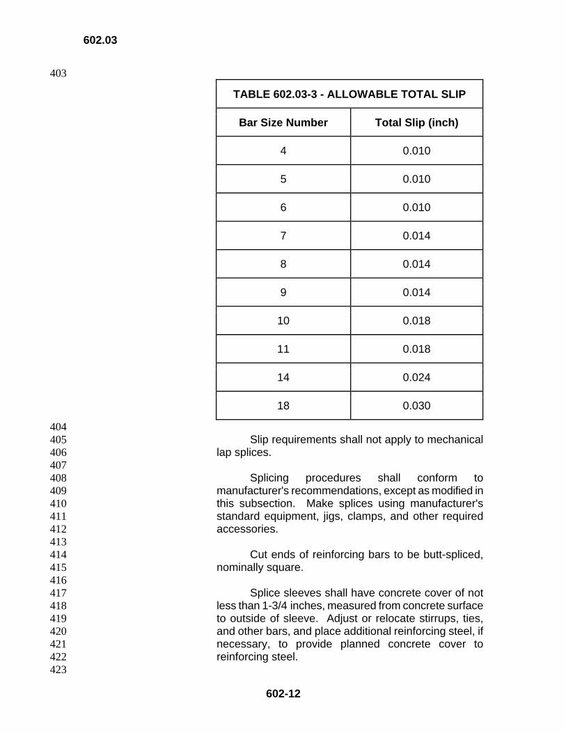
396 Total slip of reinforcing steel within splice sleeve, 397
after loading in tension to 30,000 pounds per square 398 inch and relaxing to 3,000 pounds per square inch, shall 399 not exceed values listed in Table 602.03-3 – Allowable 400 Total Slip. Slip shall be measured between gage points 401 that are clear of splice sleeve. 402
403
602.03
602-12
403
TABLE 602.03-3 - ALLOWABLE TOTAL SLIP
Bar Size Number Total Slip (inch)
4 0.010
5 0.010
6 0.010
7 0.014
8 0.014
9 0.014
10 0.018
11 0.018
14 0.024
18 0.030
404 Slip requirements shall not apply to mechanical 405
lap splices. 406 407 Splicing procedures shall conform to 408
manufacturer's recommendations, except as modified in 409 this subsection. Make splices using manufacturer's 410 standard equipment, jigs, clamps, and other required 411 accessories. 412
413 Cut ends of reinforcing bars to be butt-spliced, 414
nominally square. 415 416 Splice sleeves shall have concrete cover of not 417
less than 1-3/4 inches, measured from concrete surface 418 to outside of sleeve. Adjust or relocate stirrups, ties, 419 and other bars, and place additional reinforcing steel, if 420 necessary, to provide planned concrete cover to 421 reinforcing steel. 422
423

602.03
602-13
Submit the following information for each 424 shipment of splice material, as specified in Subsection 425 106.07 - Certificate of Compliance: 426
427 a. Type or series identification of splice 428 material and for sleeve-threaded type sleeves, 429 heat treatment lot number. 430 431 b. Bar grade and size number to be spliced, 432 by material. 433 434 c. Copy of manufacturer's technical 435 documentation giving complete data on splice 436 material and procedures. 437 438 d. Statement that splicing systems and 439 materials used in accordance with 440 manufacturer's procedures shall develop not less 441 than minimum tensile strengths, based on 442 nominal bar area, of 125 percent of specified 443 yield strength of the unspliced bars and shall 444 comply with total slip requirements and other 445 requirements indicated in the contract 446 documents. 447 448 e. Statement that splice material conforms, 449 in all respects, to details and materials of a 450 specific design accepted by the Engineer. 451 452
2. Sleeve-Filler Metal Mechanical Butt Splices. 453 Sleeve-filler metal type of mechanical butt splices shall 454 consist of a steel splice sleeve that fits closely over the 455 reinforcing bar, with ferrous filler metal in annular space 456 between reinforcing steel and sleeve, and between 457 ends of reinforcing steel. Melt filler metal by exothermic 458 reaction. Splicing process shall not fuse filler metal with 459 reinforcing steel or heat reinforcing steel to its melting 460 point, except for nominal melting of ends of reinforcing 461 steel at mid-length of splice sleeve. 462 463
Remove oversize projections and distortions of 464 reinforcing steel within sleeve by grinding. 465
466 Clean surfaces of reinforcing steel within sleeve 467
and for 2 inches beyond end of sleeve, of slag, mill 468 scale, rust, and other foreign materials. Clean either by 469 oxyacetylene torch followed by power wire brushing or 470 by abrasive blast cleaning. 471

602.03
602-14
472 Immediately prior to adding filler material to 473
splice sleeve, preheat cleaned bar ends and entire 474 splice sleeve to 300 degrees F. ± 50 degrees F. When 475 gas torches are used for preheating, do not direct flame 476 into the inside of splice sleeve. 477
478 In completed splice, sound, non-porous filler 479
metal shall be visible completely around reinforcing 480 steel, at both ends of splice sleeve and at tap hole in 481 center of sleeve. 482
483 Fill annular space between reinforcing steel and 484
sleeve with filler material, to the extent that the average 485 depth of any recess, over entire perimeter, caused by 486 use of packing ring, and voids due to other causes, at 487 each end of sleeve, does not exceed 1/2 inch. Depth of 488 recesses and voids will be measured by wire probe 489 inserted to deepest points of recesses and voids. 490
491 3. Sleeve-Threaded Mechanical Butt Splices. 492 Sleeve-threaded type of mechanical butt splices shall 493 consist of a steel splice sleeve, with tapered interior 494 threads, that joins reinforcing bars with matching 495 tapered threads. Taper threads to such a degree that 496 cross threading will not occur during assembly. 497
498 Mark each splice sleeve with heat treatment lot 499
number. 500 501 After completion of assembly, tighten splice to 502
torque value recommended by manufacturer. 503 504
4. Sleeve-Swaged Mechanical Butt Splices. 505 Sleeve-swaged type of mechanical butt splices shall 506 consist of a seamless steel sleeve applied over ends of 507 reinforcing bar and swaged to bars by means of a 508 hydraulic press. 509 510 5. Sleeve-Filler Grout Mechanical Butt Splices. 511 Sleeve-filler grout type of mechanical butt splices shall 512 consist of a steel splice sleeve that fits closely over 513 reinforcing bars with non-shrink grout filler in annular 514 space between reinforcing steel and sleeve, and 515 between ends of reinforcing steel. 516 517
Allow no vibration or movement of reinforcing bar 518 or sleeve at splice while splice is developing sufficient 519
602.03
602-15
strength to support reinforcing bar. Submit complete 520 details of bracing and clamping system to eliminate 521 vibration or movement at splice during setup of filler, as 522 specified in Subsection 105.03 - Shop Drawings. 523
524 6. Sleeve-Lockshear Bolt Mechanical Butt 525 Splices. Sleeve-lockshear bolt type of mechanical butt 526 splices shall consist of a seamless steel sleeve, center 527 hole with centering pin, and bolts that are tightened until 528 bolt heads shear off, leaving bolt ends embedded in 529 reinforcing bar. Seamless steel sleeve shall be either 530 formed into a V configuration or shall have two serrated 531 steel strips welded to inside of sleeve. 532 533 7. Two-Part Sleeve-Forged Bar Mechanical Butt 534 Splices. Two-part sleeve-forged bar type of 535 mechanical butt splices shall consist of a shop-536 machined, two-part threaded steel sleeve that interlocks 537 two hot-forged reinforcing bar ends. Forged bar ends 538 may be either shop-produced or field-produced. 539 540 8. Two-Part Sleeve-Friction Bar Mechanical Butt 541 Splices. Two-part sleeve-friction bar type of 542 mechanical butt splices shall consist of a shop 543 machined, two-part threaded steel sleeve whose ends 544 are friction welded, in the shop, to reinforcing bar ends. 545
546 (4) Qualification of Welding and Mechanical Splicing. 547 Procedures to be used in splicing reinforcing bars and welders and 548 operators who will apply these procedures shall be qualified by tests 549 performed by the Contractor on sample splices of the type to be used, 550 before making splices in the work. 551 552
For welded splices, submit written welding procedure 553 specifications (WPS) and welder qualification tests to be used that 554 conform to requirements in AWS D1.4. 555
556 Fabricator accepted by the Engineer shall produce resistance 557
butt welds. 558 559 Each operator qualification test for mechanical splices shall 560
consist of two sample splices. Each mechanical splice procedure test 561 shall consist of two sample splices. 562
563 For sleeve-filler, sleeve-threaded, sleeve-lockshear bolt, and 564
two-part sleeve friction bar mechanical butt splices, make sample 565 splices on largest reinforcing bar size to be spliced by procedure or 566

602.03
602-16
operator being tested, except that No. 14 bars may be substituted for 567 No. 18 bars. 568
569 For sleeve-swaged and two-part sleeve-forged mechanical butt 570
splices, and mechanical lap splices, make sample splices on largest 571 reinforcing bar size, of each deformation pattern to be spliced by 572 procedure or operator being tested. When joining new reinforcing bar 573 to existing reinforcing bar, make qualification test sample bars using 574 only deformation patterns of new reinforcing bar to be joined. 575
576 If operator is qualified for mechanical splicing of reinforcing bar 577
of a given size, that operator will also be considered qualified for 578 reinforcing bar sizes smaller than those used in making tests. 579
580 Perform separate operator qualification test or procedure test 581
for each mechanical splicing position and procedure that operator is 582 expected to use in the work. 583
584 Operator and procedure qualification tests may be performed 585
simultaneously. 586 587 The Engineer will accept mechanical splice procedures and 588
operators based upon acceptance of previous tests performed on 589 appropriate sample splices. 590
591 Submit completed sample splices at least 60 inches long, with 592
splice at mid-length. 593 594 Make and test sample splices in the presence of the Engineer 595
or the Engineer's authorized representative, including tests performed 596 by a commercial agency. 597
598 (5) Job Control Tests. When mechanical butt splices, shop-599 produced complete joint penetration butt-welded splices, or shop-600 produced resistance butt-welded splices are used, submit job control 601 tests from a qualified testing laboratory. Job control test shall consist 602 of fabrication, under conditions used to produce splice, and physical 603 testing of three sample splices for each lot of 150 splices. 604
605 A mechanical butt splice lot is defined as 150, or fraction 606
thereof, of the same type of mechanical butt splices used for each 607 combination of bar size and bar deformation pattern that is used in the 608 work. 609
610 A shop-produced, complete joint penetration butt-welded splice 611
lot, or shop-produced, resistance butt-welded splice lot, is defined as 612 150, or fraction thereof, of the same type of welds used for each 613
602.03
602-17
combination of bar size and bar deformation pattern that is used in the 614 work. 615
616 When joining new reinforcing bar to existing bars, make job 617
control test using only deformation patterns of new reinforcing steel to 618 be joined. 619
620 Sample splice shall consist of splice made at job site to connect 621
two 30-inch-long minimum length bars, using same splice materials, 622 position, location, and equipment, and following same procedures as 623 are being used to make splices in the work. Shorter sample splice 624 bars may be used if accepted by the Engineer. 625
626 Make and test sample splices in the presence of the Engineer 627
or the Engineer's authorized representative. 628 629 Identify sample splices with weatherproof markings prior to 630
shipment to testing laboratory. 631 632 For sleeve-threaded mechanical butt splices, fabricate 633
reinforcing bars to be used for job control tests on a random basis, 634 during thread cutting on reinforcing steel of each lot. Ship job control 635 test samples to jobsite with material they represent. 636
637 For shop-produced, complete joint penetration butt welds, 638
shop-produced, resistance butt-welded splices, and all types of 639 mechanical butt splices, except sleeve-threaded type, the Engineer 640 will designate when job control test samples are to be fabricated, and 641 will determine limits of lot represented by each job control test. 642
643 Should average of test results made on three sample splices, 644
or should more than one sample splice in any job control test fail to 645 meet requirements for splices, all splices represented by that test will 646 be rejected as specified in Subsection 106.08 - Non-Conforming 647 Materials. Rejection shall prevail unless the Contractor, at no 648 increase in contract price or contract time, obtains and submits 649 evidence acceptable to the Engineer, that strength and quality of 650 splices in the work are acceptable. 651 652 (6) Nondestructive Splice Tests. The Contractor shall perform 653 required radiographic examinations of complete joint penetration butt-654 welded splices in accordance with requirements of AWS D 1.4 and as 655 otherwise indicated in the contract documents. 656
657 Prior to radiographic examination, welds shall conform to 658
requirements of Subsection 4.4 - Quality of Welds, of AWS D1.4-98. 659 660
602.03
602-18
Perform radiographic examinations on 25 percent of all 661 complete joint penetration butt-welded splices from production lot. 662 Size of production lot will be maximum of 100 splices. The Engineer 663 will select splices that will compose production lot and also splices 664 within each production lot to be radiographically examined. 665
666 Should more than 12 percent of splices that have been 667
radiographically examined in any production lot be defective, 668 radiographically examine an additional 25 percent of splices, selected 669 by the Engineer, from same production lot. Should more than 670 12 percent of cumulative total of splices tested from same production 671 lot be defective, radiographically examine all remaining splices in lot. 672
673 Perform additional radiographic examinations due to 674
identification of defective splices, at no increase in contract price or 675 contract time. 676
677 Welds found to be defective shall be repaired in accordance 678
with requirements of ANSI/AWS D1.4 at no increase in contract price 679 or contract time. 680
681 In addition to radiographic examinations performed by the 682
Contractor, any mechanical or welded splice may be subject to 683 inspection or nondestructive testing by the Engineer. Provide 684 sufficient access facilities in shop and at jobsite to permit the Engineer 685 or the Engineer's authorized representative to perform inspection or 686 testing. 687
688 Notify the Engineer in writing 48 hours prior to performing any 689
radiographic examinations. 690 691 Radiographic procedure used shall conform to ASME Boiler 692
and Pressure Vessel Code, Section V, Article 2 and the following: 693 694
Make two exposures for each complete joint penetration 695 butt-welded splice. For each of the two exposures, center 696 radiation source on each bar to be radiographed. Make first 697 exposure with radiation source placed at zero degrees from top 698 of weld and perpendicular to weld root, and identified with 699 station mark of "0." When obstructions prevent zero degree 700 placement of radiation source for first exposure, and when 701 approved in writing by the Engineer, source may be rotated 702 around centerline of reinforcing bar, a maximum of 25 degrees. 703 Make second exposure at 90 degrees to "0" station mark and 704 identify with station mark of "90." 705
706 For field-produced, complete joint penetration butt 707
welds, radiograph no more than one weld during one exposure. 708
602.03
602-19
For shop-produced, complete joint penetration butt welds, if 709 more than one weld is to be radiographed during one 710 exposure, angle between root line of each weld and direction to 711 radiation source shall be not less than 65 degrees. 712
713 Make radiographs by either X-ray or gamma ray. 714
Radiographs made by X-ray or gamma rays shall have 715 densities of not less than 2.3 or more than 3.5, in area of 716 interest. Tolerance of 0.05 in density will be allowed for 717 densitometer variations. Gamma rays shall be from iridium 718 192 isotope and emitting specimen shall not exceed 0.175 inch 719 in greatest diagonal dimension. 720
721 Place radiographic film perpendicular to radiation source 722
at all times; parallel to root line of weld, unless source 723 placement determines that film must be turned; and as close to 724 weld root as possible. 725
726 Maintain minimum source-to-film distance such that 727
radiographs maintain maximum geometric unsharpness of 728 0.020, regardless of reinforcing bar size. 729
730 Place penetrameters on source side of bar and 731
perpendicular to radiation source at all times. Place one 732 penetrameter in center of each bar to be radiographed, 733 perpendicular to weld root, and adjacent to weld. 734 Penetrameter images shall not appear in weld area. 735
736 When radiography of more than one weld is being 737
performed per exposure, include minimum of one pentrameter 738 per bar for each exposure, or three penetrameters per 739 exposure. When three penetrameters per exposure are used, 740 place one penetrameter on each of the two outermost bars of 741 the exposure, and place remaining penetrameter on centrally 742 located bar. 743
744 Allowable weld buildup of 0.16 inch may be added to 745
total material thickness when determining proper penetrameter 746 selection. No image quality indicator equivalency will be 747 accepted. Wire penetrameters or penetrameter blocks will not 748 be allowed. 749
750 Shim penetrameters using radiographically identical 751
material. Penetrameter image densities shall be minimum of 752 2.0 and maximum of 3.6. 753
754 Use Class 1 radiographic film, regardless of reinforcing 755
bar size. 756

602.03
602-20
757 Keep radiographs free of film artifacts and processing 758
defects, including streaks, scratches, pressure marks, or marks 759 made for identifying film or for welding indications. 760
761 Clearly identify each splice on each radiograph. Before 762
radiographic inspection begins, radiograph identification and 763 marking system shall be established between the Contractor 764 and the Engineer. Identify film by lead numbers only. Etching, 765 flashing, or writing in identifications of any type will not be 766 permitted. Make each piece of film identification information 767 legible and include, as a minimum, the following information: 768 Contractor's name, date, name of nondestructive testing firm, 769 initials of radiographer, contract number, part number, and 770 weld number. Place the letter "R" and repair number directly 771 after weld number to designate radiograph of a repaired weld. 772
773 Develop radiographic film within time range of one 774
minute less to one minute more than film manufacturer's 775 recommended maximum development time. Sight 776 development will not be allowed. 777
778 Use processing chemistry with consistent mixture and 779
quality. Keep processing rinses and tanks clean. Maintain 780 records of all developing processes and any chemical changes 781 to developing processes. Submit those records to the 782 Engineer upon request. The Engineer may request, at any 783 time, that a sheet of unexposed film be processed in the 784 presence of the Engineer, to verify processing chemical and 785 rinse quality. 786
787 Record results of radiographic interpretations on signed 788
certification and keep copy with film packet. 789 790 Include developer temperature, developing time, fixing 791
duration, and rinse times in technique sheets prepared in 792 accordance with ASME Boiler and Pressure Vessel Code, 793 Section V, Article 2, Section T-291. 794
795 (F) Splicing of Welded Wire Fabric. Overlap flat sheets of welded wire 796 fabric (WWF) to maintain uniform strength. Fasten sheets of WWF at ends 797 and edges. Use edge lap not less than the following: one spacing of cross 798 wires plus 2 inches; or 6 inches; or the numerical value of the longitudinal 799 wire size (W-Size Number) times 4.3 divided by the longitudinal wire spacing 800 in inches. 801 602.03 802
602.04 Measurement. Reinforcing steel will be paid on a lump sum basis. 803 Measurement for payment will not apply. 804
602.05
602-21
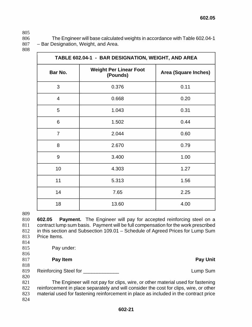
805 The Engineer will base calculated weights in accordance with Table 602.04-1 806
– Bar Designation, Weight, and Area. 807 808
TABLE 602.04-1 - BAR DESIGNATION, WEIGHT, AND AREA
Bar No. Weight Per Linear Foot (Pounds) Area (Square Inches)
3 0.376 0.11
4 0.668 0.20
5 1.043 0.31
6 1.502 0.44
7 2.044 0.60
8 2.670 0.79
9 3.400 1.00
10 4.303 1.27
11 5.313 1.56
14 7.65 2.25
18 13.60 4.00
809 602.05 Payment. The Engineer will pay for accepted reinforcing steel on a 810 contract lump sum basis. Payment will be full compensation for the work prescribed 811 in this section and Subsection 109.01 – Schedule of Agreed Prices for Lump Sum 812 Price Items. 813 814
Pay under: 815 816 Pay Item Pay Unit 817
818 Reinforcing Steel for _____________ Lump Sum 819 820
The Engineer will not pay for clips, wire, or other material used for fastening 821 reinforcement in place separately and will consider the cost for clips, wire, or other 822 material used for fastening reinforcement in place as included in the contract price 823
824

602.05
602-22
of the various contract pay items. The cost is for the work prescribed in this section 824 and the contract documents. 825
826 The Engineer will not pay for welded wire fabric or bar mat reinforcement 827
separately and will consider the cost for welded wire fabric or bar mat reinforcement 828 as included in the contract price of the various contract pay items. The cost is for 829 the work prescribed in this section and the contract documents. 830 831 832
END OF SECTION 602 833