6005 Servo Tank Gauge - varec.com · IOM007NVAE2415 Automation Solutions for oil & gas, defense and...
196
IOM007NVAE2415 Automation Solutions for oil & gas, defense and aviation applications Installation and Operations Manual Dispatch and Fuels Accounting 6005 Servo Tank Gauge Intelligent tank gauge for high accuracy liquid level measurement in storage and process applications Software Version 4.27G
Transcript of 6005 Servo Tank Gauge - varec.com · IOM007NVAE2415 Automation Solutions for oil & gas, defense and...

IOM007NVAE2415
Automation Solutions for oil & gas, defense and aviation applications
Installation and Operations M
anualD
ispatch and Fuels Accounting
6005 Servo Tank GaugeIntelligent tank gauge for high accuracy liquid level measurement in storage and process applicationsSoftware Version 4.27G


Varec, Inc. iii
Copyright
All rights reserved. Printed in the United States of America.
Except as permitted under the United States Copyright Act of 1976, no part of this publication may be reproduced, stored in a retrieval system or transmitted in any form or by any means - electronic, mechanical, photocopying, recording, or otherwise - without the prior written permission of the Publisher:
Varec, Inc.5834 Peachtree Corners EastPeachtree Corners (Atlanta), Georgia 30092Phone: (770) 447-9202Fax: (770) 662-8939
Trademarks Acknowledged
Varec, Inc. recognizes all other trademarks. Trademarks of other products mentioned in this manual are held by the companies producing them.
FuelsManager®, TankView®, TacFuels®, Varec®, and FuelsManager IntoPlane® are registered trademarks of Varec, Inc.
HART® Registered trademark of HART Communication Foundation, Austin, USA
ToF® Registered trademark of the company Endress+Hauser GmbH+Co. KG, Maulburg, Germany
FieldCare® Registered trademark of the company Endress+Hauser Flowtec AG, Rheinach, CH
All other product and service names mentioned are the trademarks of their respective companies.
Product Approvals
This document and the information provided within are controlled by the approvals agency(s) listed below. All changes to this document must be submitted to and approved by the agency(s) before public release.
• FM Approvals (FM)• Canadian Standards Association (CSA)• DERKA (ATEX)

Disclaimer of Warranties
The contract between the Seller and the Buyer states the entire obligation of the Seller. The contents of this instruction manual shall not become part of or modify any prior or existing agreement, commitment, or relationship between the Seller and Buyer. There are no express or implied warranties set out in this instruction manual. The only warranties that apply are those in the existing contract between the Seller and Buyer.
The 6005 Servo Tank Gauge (STG) has not been tested by Varec under all possible operational conditions, and Varec may not have all the data relative to your application. The information in this instruction manual is not all inclusive and does not and cannot take into account all unique situations. Consequently, the user should review this product literature in view of his or her application. If you have any further questions, please contact Varec for assistance at (770) 447-9202.
Limitations of Seller's Liability
In the event that a court holds that this instruction manual created some new warranties, Seller's liability shall be limited to repair or replacement under the standard warranty clause. In no case shall the Seller's liability exceed that stated as Limitations of Remedy in the contract between the Seller and Buyer.
Use of parts that are not manufactured or supplied by Varec voids any warranty and relieves Varec of any obligation to service the product under warranty. Varec recommends the use of only Varec manufactured or supplied parts to maintain or service Varec 6005 Servo Tank Gauges.
Terms of Use
The information provided in this document is provided "as is" without warranty of any kind. Varec, Inc. disclaim all warranties, either express or implied, including the warranties of merchantability and fitness for a particular purpose. In no event shall Varec, Inc. or its suppliers be liable for any damages whatsoever including direct, indirect, incidental, consequential, loss of business profits or special damages, even if Varec, Inc. or its suppliers have been advised of the possibility of such damages.
This manual is solely intended to describe product installation and functions and should not be used for any other purpose. It is subject to change without prior notice. This manual was prepared with the highest degree of care. However, should you find any errors or have any questions, contact one of our service offices, your local sales agent, or Varec at:
Varec, Inc.5834 Peachtree Corners EastPeachtree Corners (Atlanta), Georgia 30092Phone: (770) 447-9202Fax: (770) 662-8939
iv Installation and Operations Manual

Safety Precaution Definitions
Caution! Damage to equipment may result if this precaution is disregarded.
Warning! Direct injury to personnel or damage to equipment which can cause injury to personnel may result if this precaution is not followed.
Safety Precautions
Read this manual carefully and make sure you understand its contents before using this product. Follow all instructions and safety guidelines presented in this manual when using this product. If the user does not follow these instructions properly, Varec cannot guarantee the safety of the system.
Note Comply with all applicable regulations, codes, and standards. For safety precautions, the user should refer to the appropriate industry or military standards.
Caution! Electrical Hazard! Read and understand static and lightning electrical protection and grounding described in API 2003. Make certain that the tank installation, operation, and maintenance conforms with the practice set forth therein.
Varec, Inc. v

vi Installation and Operations Manual

Varec, Inc. vii
Contents
1 Safety Instructions . . . . . . . . . . . . . . . . . . . . . . . . . . . . . . . . . . . . . . . . . . . 1
Designated Use . . . . . . . . . . . . . . . . . . . . . . . . . . . . . . . . . . . . . . . . . . . . . . . . . . . . . . . . . . . .1Installation, Commissioning, and Operation . . . . . . . . . . . . . . . . . . . . . . . . . . . . . . . . . . . . . .1Product Requirements . . . . . . . . . . . . . . . . . . . . . . . . . . . . . . . . . . . . . . . . . . . . . . . . . . . . . . .1
Power source . . . . . . . . . . . . . . . . . . . . . . . . . . . . . . . . . . . . . . . . . . . . . . . . . . . . . . . .1Use in hazardous areas . . . . . . . . . . . . . . . . . . . . . . . . . . . . . . . . . . . . . . . . . . . . . . . .1External connection . . . . . . . . . . . . . . . . . . . . . . . . . . . . . . . . . . . . . . . . . . . . . . . . . . .2
Operational Safety . . . . . . . . . . . . . . . . . . . . . . . . . . . . . . . . . . . . . . . . . . . . . . . . . . . . . . . . . .2Hazardous area . . . . . . . . . . . . . . . . . . . . . . . . . . . . . . . . . . . . . . . . . . . . . . . . . . . . . . .2Power supply . . . . . . . . . . . . . . . . . . . . . . . . . . . . . . . . . . . . . . . . . . . . . . . . . . . . . . . . .2
Electrostatic Charge . . . . . . . . . . . . . . . . . . . . . . . . . . . . . . . . . . . . . . . . . . . . . . . . . . . . . . . . .3Notes on Safety Conventions and Symbols . . . . . . . . . . . . . . . . . . . . . . . . . . . . . . . . . . . . . . .4
2 Installation . . . . . . . . . . . . . . . . . . . . . . . . . . . . . . . . . . . . . . . . . . . . . . . . . 7
Incoming Acceptance, Transport, and Storage . . . . . . . . . . . . . . . . . . . . . . . . . . . . . . . . . . . .7Incoming Acceptance . . . . . . . . . . . . . . . . . . . . . . . . . . . . . . . . . . . . . . . . . . . . . . . . . .7Transport . . . . . . . . . . . . . . . . . . . . . . . . . . . . . . . . . . . . . . . . . . . . . . . . . . . . . . . . . . .7Storage . . . . . . . . . . . . . . . . . . . . . . . . . . . . . . . . . . . . . . . . . . . . . . . . . . . . . . . . . . . . .7
Terms Related to the Tank Measurements . . . . . . . . . . . . . . . . . . . . . . . . . . . . . . . . . . . . . . .8Product Dimensions . . . . . . . . . . . . . . . . . . . . . . . . . . . . . . . . . . . . . . . . . . . . . . . . . . . . . . . .9Necessary Tools for Installation . . . . . . . . . . . . . . . . . . . . . . . . . . . . . . . . . . . . . . . . . . . . . . . .9
3 Identification . . . . . . . . . . . . . . . . . . . . . . . . . . . . . . . . . . . . . . . . . . . . . . 11
Device Designation . . . . . . . . . . . . . . . . . . . . . . . . . . . . . . . . . . . . . . . . . . . . . . . . . . . . . . . . .11Nameplate . . . . . . . . . . . . . . . . . . . . . . . . . . . . . . . . . . . . . . . . . . . . . . . . . . . . . . . . . .11
Scope of Delivery . . . . . . . . . . . . . . . . . . . . . . . . . . . . . . . . . . . . . . . . . . . . . . . . . . . . . . . . .13Certificates and Approvals . . . . . . . . . . . . . . . . . . . . . . . . . . . . . . . . . . . . . . . . . . . . . . . . . . .14
CE mark, Declaration of Conformity . . . . . . . . . . . . . . . . . . . . . . . . . . . . . . . . . . . .14
4 Mounting . . . . . . . . . . . . . . . . . . . . . . . . . . . . . . . . . . . . . . . . . . . . . . . . . 15
Application Drawing for Tank . . . . . . . . . . . . . . . . . . . . . . . . . . . . . . . . . . . . . . . . . . . . . . . . .15Mounting without Guide System . . . . . . . . . . . . . . . . . . . . . . . . . . . . . . . . . . . . . . . . . . . . . . .16Mounting with Stilling Well . . . . . . . . . . . . . . . . . . . . . . . . . . . . . . . . . . . . . . . . . . . . . . . . . . .17
Pipe diameter . . . . . . . . . . . . . . . . . . . . . . . . . . . . . . . . . . . . . . . . . . . . . . . . . . . . . . .17Recommendations for Mounting . . . . . . . . . . . . . . . . . . . . . . . . . . . . . . . . . . . . . . . .20
Mounting with Guide Wire . . . . . . . . . . . . . . . . . . . . . . . . . . . . . . . . . . . . . . . . . . . . . . . . . . .20Guide Wire Installation . . . . . . . . . . . . . . . . . . . . . . . . . . . . . . . . . . . . . . . . . . . . . . . .20Weight Calibration Method for Guide Wire Installation . . . . . . . . . . . . . . . . . . . . . . . .22Tank Type . . . . . . . . . . . . . . . . . . . . . . . . . . . . . . . . . . . . . . . . . . . . . . . . . . . . . . . . . .23Floating roof tank and /or covered floating roof Tank . . . . . . . . . . . . . . . . . . . . . . . . .25High or Low Temperature Tank . . . . . . . . . . . . . . . . . . . . . . . . . . . . . . . . . . . . . . . . .27
Mounting Preparations . . . . . . . . . . . . . . . . . . . . . . . . . . . . . . . . . . . . . . . . . . . . . . . . . . . . .28Flange . . . . . . . . . . . . . . . . . . . . . . . . . . . . . . . . . . . . . . . . . . . . . . . . . . . . . . . . . . . . .28
Electrostatic Charge . . . . . . . . . . . . . . . . . . . . . . . . . . . . . . . . . . . . . . . . . . . . . . . . . . . . . . . .30Installation for Wire Drum and Displacer . . . . . . . . . . . . . . . . . . . . . . . . . . . . . . . . . . . . . . . .30
viii Installation and Operations Manual
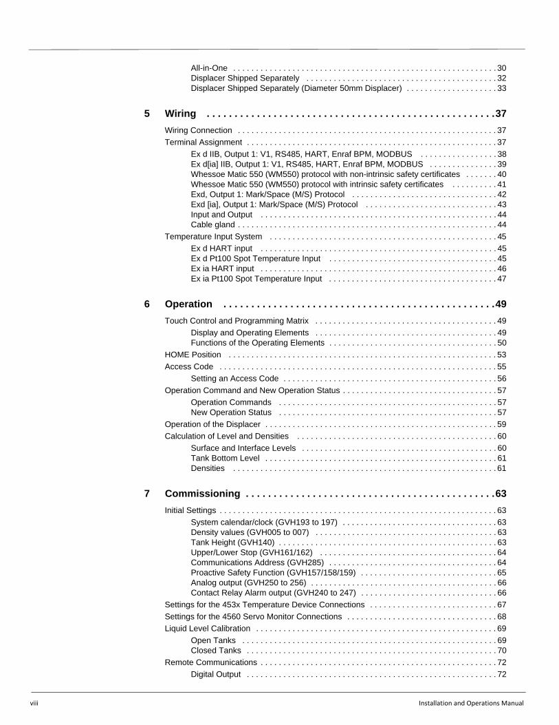
All-in-One . . . . . . . . . . . . . . . . . . . . . . . . . . . . . . . . . . . . . . . . . . . . . . . . . . . . . . . . . . 30Displacer Shipped Separately . . . . . . . . . . . . . . . . . . . . . . . . . . . . . . . . . . . . . . . . . . 32Displacer Shipped Separately (Diameter 50mm Displacer) . . . . . . . . . . . . . . . . . . . . 33
5 Wiring . . . . . . . . . . . . . . . . . . . . . . . . . . . . . . . . . . . . . . . . . . . . . . . . . . . .37
Wiring Connection . . . . . . . . . . . . . . . . . . . . . . . . . . . . . . . . . . . . . . . . . . . . . . . . . . . . . . . . . 37Terminal Assignment . . . . . . . . . . . . . . . . . . . . . . . . . . . . . . . . . . . . . . . . . . . . . . . . . . . . . . . 37
Ex d IIB, Output 1: V1, RS485, HART, Enraf BPM, MODBUS . . . . . . . . . . . . . . . . . 38Ex d[ia] IIB, Output 1: V1, RS485, HART, Enraf BPM, MODBUS . . . . . . . . . . . . . . . 39Whessoe Matic 550 (WM550) protocol with non-intrinsic safety certificates . . . . . . . 40Whessoe Matic 550 (WM550) protocol with intrinsic safety certificates . . . . . . . . . . 41Exd, Output 1: Mark/Space (M/S) Protocol . . . . . . . . . . . . . . . . . . . . . . . . . . . . . . . . 42Exd [ia], Output 1: Mark/Space (M/S) Protocol . . . . . . . . . . . . . . . . . . . . . . . . . . . . . 43Input and Output . . . . . . . . . . . . . . . . . . . . . . . . . . . . . . . . . . . . . . . . . . . . . . . . . . . . 44Cable gland . . . . . . . . . . . . . . . . . . . . . . . . . . . . . . . . . . . . . . . . . . . . . . . . . . . . . . . . . 44
Temperature Input System . . . . . . . . . . . . . . . . . . . . . . . . . . . . . . . . . . . . . . . . . . . . . . . . . . 45Ex d HART input . . . . . . . . . . . . . . . . . . . . . . . . . . . . . . . . . . . . . . . . . . . . . . . . . . . . 45Ex d Pt100 Spot Temperature Input . . . . . . . . . . . . . . . . . . . . . . . . . . . . . . . . . . . . . 45Ex ia HART input . . . . . . . . . . . . . . . . . . . . . . . . . . . . . . . . . . . . . . . . . . . . . . . . . . . . 46Ex ia Pt100 Spot Temperature Input . . . . . . . . . . . . . . . . . . . . . . . . . . . . . . . . . . . . . 47
6 Operation . . . . . . . . . . . . . . . . . . . . . . . . . . . . . . . . . . . . . . . . . . . . . . . . .49
Touch Control and Programming Matrix . . . . . . . . . . . . . . . . . . . . . . . . . . . . . . . . . . . . . . . . 49Display and Operating Elements . . . . . . . . . . . . . . . . . . . . . . . . . . . . . . . . . . . . . . . . 49Functions of the Operating Elements . . . . . . . . . . . . . . . . . . . . . . . . . . . . . . . . . . . . . 50
HOME Position . . . . . . . . . . . . . . . . . . . . . . . . . . . . . . . . . . . . . . . . . . . . . . . . . . . . . . . . . . . 53Access Code . . . . . . . . . . . . . . . . . . . . . . . . . . . . . . . . . . . . . . . . . . . . . . . . . . . . . . . . . . . . . 55
Setting an Access Code . . . . . . . . . . . . . . . . . . . . . . . . . . . . . . . . . . . . . . . . . . . . . . . 56Operation Command and New Operation Status . . . . . . . . . . . . . . . . . . . . . . . . . . . . . . . . . . 57
Operation Commands . . . . . . . . . . . . . . . . . . . . . . . . . . . . . . . . . . . . . . . . . . . . . . . . 57New Operation Status . . . . . . . . . . . . . . . . . . . . . . . . . . . . . . . . . . . . . . . . . . . . . . . . 57
Operation of the Displacer . . . . . . . . . . . . . . . . . . . . . . . . . . . . . . . . . . . . . . . . . . . . . . . . . . . 59Calculation of Level and Densities . . . . . . . . . . . . . . . . . . . . . . . . . . . . . . . . . . . . . . . . . . . . 60
Surface and Interface Levels . . . . . . . . . . . . . . . . . . . . . . . . . . . . . . . . . . . . . . . . . . . 60Tank Bottom Level . . . . . . . . . . . . . . . . . . . . . . . . . . . . . . . . . . . . . . . . . . . . . . . . . . . 61Densities . . . . . . . . . . . . . . . . . . . . . . . . . . . . . . . . . . . . . . . . . . . . . . . . . . . . . . . . . . 61
7 Commissioning . . . . . . . . . . . . . . . . . . . . . . . . . . . . . . . . . . . . . . . . . . . . .63
Initial Settings . . . . . . . . . . . . . . . . . . . . . . . . . . . . . . . . . . . . . . . . . . . . . . . . . . . . . . . . . . . . . 63System calendar/clock (GVH193 to 197) . . . . . . . . . . . . . . . . . . . . . . . . . . . . . . . . . . 63Density values (GVH005 to 007) . . . . . . . . . . . . . . . . . . . . . . . . . . . . . . . . . . . . . . . . 63Tank Height (GVH140) . . . . . . . . . . . . . . . . . . . . . . . . . . . . . . . . . . . . . . . . . . . . . . . . 63Upper/Lower Stop (GVH161/162) . . . . . . . . . . . . . . . . . . . . . . . . . . . . . . . . . . . . . . . 64Communications Address (GVH285) . . . . . . . . . . . . . . . . . . . . . . . . . . . . . . . . . . . . . 64Proactive Safety Function (GVH157/158/159) . . . . . . . . . . . . . . . . . . . . . . . . . . . . . . 65Analog output (GVH250 to 256) . . . . . . . . . . . . . . . . . . . . . . . . . . . . . . . . . . . . . . . . . 66Contact Relay Alarm output (GVH240 to 247) . . . . . . . . . . . . . . . . . . . . . . . . . . . . . . 66
Settings for the 453x Temperature Device Connections . . . . . . . . . . . . . . . . . . . . . . . . . . . . 67Settings for the 4560 Servo Monitor Connections . . . . . . . . . . . . . . . . . . . . . . . . . . . . . . . . . 68Liquid Level Calibration . . . . . . . . . . . . . . . . . . . . . . . . . . . . . . . . . . . . . . . . . . . . . . . . . . . . . 69
Open Tanks . . . . . . . . . . . . . . . . . . . . . . . . . . . . . . . . . . . . . . . . . . . . . . . . . . . . . . . . 69Closed Tanks . . . . . . . . . . . . . . . . . . . . . . . . . . . . . . . . . . . . . . . . . . . . . . . . . . . . . . . 70
Remote Communications . . . . . . . . . . . . . . . . . . . . . . . . . . . . . . . . . . . . . . . . . . . . . . . . . . . . 72Digital Output . . . . . . . . . . . . . . . . . . . . . . . . . . . . . . . . . . . . . . . . . . . . . . . . . . . . . . . 72

Contents
Varec, Inc. ix
Whessoe Matic 550 (WM550) Communication Board Setting . . . . . . . . . . . . . . . . . .73Mark/Space (M/S) communication board setting . . . . . . . . . . . . . . . . . . . . . . . . . . . .73ENRAF Bi Phase communication board (COM-3) setting . . . . . . . . . . . . . . . . . . . . . .76Analog Output . . . . . . . . . . . . . . . . . . . . . . . . . . . . . . . . . . . . . . . . . . . . . . . . . . . . . . .77Contact Relay Alarm Output . . . . . . . . . . . . . . . . . . . . . . . . . . . . . . . . . . . . . . . . . . .78Relay Logic . . . . . . . . . . . . . . . . . . . . . . . . . . . . . . . . . . . . . . . . . . . . . . . . . . . . . . . .79
Density Measurement and Density Profile Measurement . . . . . . . . . . . . . . . . . . . . . . . . . . .80Spot Density Measurement . . . . . . . . . . . . . . . . . . . . . . . . . . . . . . . . . . . . . . . . . . . . .80Density Profile Measurement . . . . . . . . . . . . . . . . . . . . . . . . . . . . . . . . . . . . . . . . . . .82
Interface Measurement . . . . . . . . . . . . . . . . . . . . . . . . . . . . . . . . . . . . . . . . . . . . . . . . . . . . .89Sealing of the 6005 STG . . . . . . . . . . . . . . . . . . . . . . . . . . . . . . . . . . . . . . . . . . . . . . . . . . . .90
8 Maintenance . . . . . . . . . . . . . . . . . . . . . . . . . . . . . . . . . . . . . . . . . . . . . . 91
Exterior Cleaning . . . . . . . . . . . . . . . . . . . . . . . . . . . . . . . . . . . . . . . . . . . . . . . . . . . . . . . . . .91Replacing Seals . . . . . . . . . . . . . . . . . . . . . . . . . . . . . . . . . . . . . . . . . . . . . . . . . . . . . . . . . . .91Repairs . . . . . . . . . . . . . . . . . . . . . . . . . . . . . . . . . . . . . . . . . . . . . . . . . . . . . . . . . . . . . . . . .91Repairs to Ex-approved Devices . . . . . . . . . . . . . . . . . . . . . . . . . . . . . . . . . . . . . . . . . . . . . .91Replacement . . . . . . . . . . . . . . . . . . . . . . . . . . . . . . . . . . . . . . . . . . . . . . . . . . . . . . . . . . . . .92
9 Diagnosis and Troubleshooting . . . . . . . . . . . . . . . . . . . . . . . . . . . . . . 93
Selection of Diagnostic Code and History . . . . . . . . . . . . . . . . . . . . . . . . . . . . . . . . . . . . . . .93Error and Status Messages . . . . . . . . . . . . . . . . . . . . . . . . . . . . . . . . . . . . . . . . . . . . . . . . . .94Diagnostics and Troubleshooting: Flowcharts . . . . . . . . . . . . . . . . . . . . . . . . . . . . . . . . . . . .97Setting after Parts Replacement . . . . . . . . . . . . . . . . . . . . . . . . . . . . . . . . . . . . . . . . . . . . . .102Intelligent Function . . . . . . . . . . . . . . . . . . . . . . . . . . . . . . . . . . . . . . . . . . . . . . . . . . . . . . .104
Maintenance prediction function . . . . . . . . . . . . . . . . . . . . . . . . . . . . . . . . . . . . . . . .104Spare Parts . . . . . . . . . . . . . . . . . . . . . . . . . . . . . . . . . . . . . . . . . . . . . . . . . . . . . . . . . . . . .104
6005 STG Spare Parts . . . . . . . . . . . . . . . . . . . . . . . . . . . . . . . . . . . . . . . . . . . . . . .1056005 STG Spare Parts List . . . . . . . . . . . . . . . . . . . . . . . . . . . . . . . . . . . . . . . . . . . .105
Return . . . . . . . . . . . . . . . . . . . . . . . . . . . . . . . . . . . . . . . . . . . . . . . . . . . . . . . . . . . . . . . . .108Disposal . . . . . . . . . . . . . . . . . . . . . . . . . . . . . . . . . . . . . . . . . . . . . . . . . . . . . . . . . . . . . . . .108Gauge Software . . . . . . . . . . . . . . . . . . . . . . . . . . . . . . . . . . . . . . . . . . . . . . . . . . . . . . . . . .108Contact Addresses of Varec . . . . . . . . . . . . . . . . . . . . . . . . . . . . . . . . . . . . . . . . . . . . . . . .109
10 Displacer and Measuring Wire . . . . . . . . . . . . . . . . . . . . . . . . . . . . . . . 111
Shape, Diameter, and Material . . . . . . . . . . . . . . . . . . . . . . . . . . . . . . . . . . . . . . . . . . . . . .111Displacer . . . . . . . . . . . . . . . . . . . . . . . . . . . . . . . . . . . . . . . . . . . . . . . . . . . . . . . . . .111Measuring Wire . . . . . . . . . . . . . . . . . . . . . . . . . . . . . . . . . . . . . . . . . . . . . . . . . . . . .111
Alarm History Display . . . . . . . . . . . . . . . . . . . . . . . . . . . . . . . . . . . . . . . . . . . . . . . . . . . . . .112List of Alarm Messages . . . . . . . . . . . . . . . . . . . . . . . . . . . . . . . . . . . . . . . . . . . . . . . . . . . .113Hall Sensors . . . . . . . . . . . . . . . . . . . . . . . . . . . . . . . . . . . . . . . . . . . . . . . . . . . . . . . . . . . .113Initial Weight Calibration . . . . . . . . . . . . . . . . . . . . . . . . . . . . . . . . . . . . . . . . . . . . . . . . . . .115
Displacer weight calibration — level measurement function only . . . . . . . . . . . . . . .115Displacer Weight Calibration . . . . . . . . . . . . . . . . . . . . . . . . . . . . . . . . . . . . . . . . . .117
11 Programming Matrix . . . . . . . . . . . . . . . . . . . . . . . . . . . . . . . . . . . . . . . 119
Description of the Programming Matrix . . . . . . . . . . . . . . . . . . . . . . . . . . . . . . . . . . . . . . . .129

x Installation and Operations Manual
12 Technical Data . . . . . . . . . . . . . . . . . . . . . . . . . . . . . . . . . . . . . . . . . . . . .165
13 Order Codes . . . . . . . . . . . . . . . . . . . . . . . . . . . . . . . . . . . . . . . . . . . . . .167
A Appendix . . . . . . . . . . . . . . . . . . . . . . . . . . . . . . . . . . . . . . . . . . . . . . . . . . .1
RS-485 MODBUS (COM- 5) Terminator . . . . . . . . . . . . . . . . . . . . . . . . . . . . . . . . . . . . . . . . . 1How to set terminator switch . . . . . . . . . . . . . . . . . . . . . . . . . . . . . . . . . . . . . . . . . . . . . 1
Changing Measurement Wire . . . . . . . . . . . . . . . . . . . . . . . . . . . . . . . . . . . . . . . . . . . . . . . . . . 3Winding wire onto wire drum . . . . . . . . . . . . . . . . . . . . . . . . . . . . . . . . . . . . . . . . . . . . . 3
Displacer . . . . . . . . . . . . . . . . . . . . . . . . . . . . . . . . . . . . . . . . . . . . . . . . . . . . . . . . . . . . . . . . . 6Displacer installation . . . . . . . . . . . . . . . . . . . . . . . . . . . . . . . . . . . . . . . . . . . . . . . . . . . 6PTFE Displacer Installation . . . . . . . . . . . . . . . . . . . . . . . . . . . . . . . . . . . . . . . . . . . . . . 7Displacers . . . . . . . . . . . . . . . . . . . . . . . . . . . . . . . . . . . . . . . . . . . . . . . . . . . . . . . . . 10

Varec, Inc. 1
Chapter 1
Safety Instructions
Designated Use The 6005 Servo Tank Gauge (STG) intelligent tank gauges are designed for high accuracy liquid level measurement in storage and process applications.
They fulfill the exact demands of tank inventory management, loss control, total cost saving and safe operation.
Tank mounted intelligence makes the 6005 STG ideal for single or multi-task installation, converting a wide range of measurement functions.
Installation, Commissioning, and Operation • Mounting, electrical installation, start-up and maintenance of the instrument may
only be carried out by trained personnel authorized by the operator of the facility.• Personnel must absolutely and without fail read and understand this Operating
Manual before carrying out its instructions.• The instrument may only be operated by personnel who are authorized and trained
by the operator of the facility. All instructions in this manual are to be observed without fail.
• The installer must make sure that the measuring system is correctly wired according to the wiring diagrams. The measuring system is to be grounded.
• Please observe all provisions valid for your country and pertaining to the opening and repairing of electrical devices.
Product Requirements
Power source
Check the voltage of the power supply before connecting it to the product. It should be the exact voltage required for proper operation of the product.
Use in hazardous areas
When using the product in the first or second-class hazard location (Zone 1 or Zone 2) be sure to use an intrinsically safe or pressure and explosion-proof apparatus. Take the utmost care during the installation, wiring, and piping of such apparatus to ensure the safety of the system.
6005 Servo Tank Gauge
2 Installation and Operations Manual
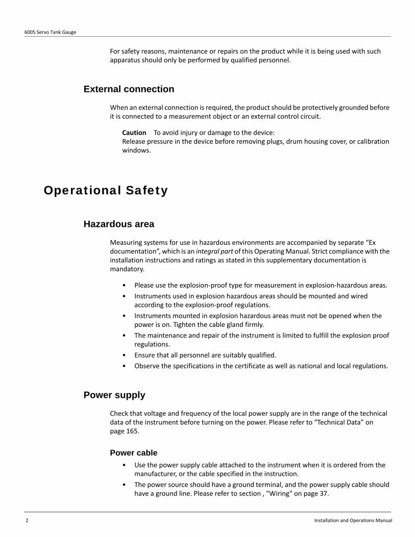
For safety reasons, maintenance or repairs on the product while it is being used with such apparatus should only be performed by qualified personnel.
External connection
When an external connection is required, the product should be protectively grounded before it is connected to a measurement object or an external control circuit.
Caution To avoid injury or damage to the device: Release pressure in the device before removing plugs, drum housing cover, or calibration windows.
Operational Safety
Hazardous area
Measuring systems for use in hazardous environments are accompanied by separate “Ex documentation”, which is an integral part of this Operating Manual. Strict compliance with the installation instructions and ratings as stated in this supplementary documentation is mandatory.
• Please use the explosion-proof type for measurement in explosion-hazardous areas.• Instruments used in explosion hazardous areas should be mounted and wired
according to the explosion-proof regulations.• Instruments mounted in explosion hazardous areas must not be opened when the
power is on. Tighten the cable gland firmly.• The maintenance and repair of the instrument is limited to fulfill the explosion proof
regulations.• Ensure that all personnel are suitably qualified.• Observe the specifications in the certificate as well as national and local regulations.
Power supply
Check that voltage and frequency of the local power supply are in the range of the technical data of the instrument before turning on the power. Please refer to “Technical Data” on page 165.
Power cable
• Use the power supply cable attached to the instrument when it is ordered from the manufacturer, or the cable specified in the instruction.
• The power source should have a ground terminal, and the power supply cable should have a ground line. Please refer to section , "Wiring" on page 37.

Chapter 1 - Safety Instructions
Varec, Inc. 3
Grounding
• Do not unground device while the power supply is turned on. Doing so may cause a short circuit, resulting in damage to devices, as well as personal injury from electrical shock.
Wiring
Verify the instrument is grounded before connecting input and output to another system.
Use of the Instrument
The 6005 STG is designed for level measurement of a liquid in a storage tank or similar facilities.
Auxiliary instruments may be connected, as specified in this manual. However, the performance of the connected instruments is not guaranteed. Please refer to manufacture supplied instructions when connecting after-market auxiliary devices.
If device is used for any purpose other than intended, device damage, as well as personal injury or death may result. Devices are supplied with IEC class 1 (ground terminal).
Caution Changes or modifications not expressly approved by the party responsible for compliance are strictly prohibited. Unauthorized modifications can cause malfunctions or damage, resulting in serious injury or death.
Electrostatic Charge Mounting with a stilling well (stilling pipe) is recommended for use in a tank containing flammable liquid with conductivity less than or equal to 10-8 S/m.
In case of installation without a pipe, allow enough stilling time according to the table below before lowering the level gauge down to the liquid surface. When a stilling pipe is used, the stilling time is shown as in column “≤10” in Table 1.
Table 1: Stilling Time for a Stilling Pipe
Conductivity(S/cm)
Reference: Stilling time (min.)
Liquid volume in a tank (m3)
≤10 10~50 50~100 ≥5000
≥10-8 ≥1 ≥1 ≥1 ≥2
10-12 ~10-8 ≥2 ≥3 ≥10 ≥30
10-14~10-12 ≥4 ≥5 ≥60 ≥120
≤10-14 ≥10 ≥10 ≥120 ≥240
(Japan National Institute of Occupational Safety and Health 2007)

6005 Servo Tank Gauge
4 Installation and Operations Manual
Notes on Safety Conventions and SymbolsIn order to highlight safety-relevant or alternative operating procedures in the manual, the following conventions have been used, each indicated by a corresponding symbol in the margin.
Safety Conventions
Warning A warning highlights actions or procedures which, if not performed correctly, will lead to personal injury, a safety hazard or destruction of the instrument
Caution Caution highlights actions or procedures which, if not performed correctly, may lead to personal injury or incorrect functioning of the instrument
Note A note highlights actions or procedures which, if not performed correctly, may indirectly affect operation or may lead to an instrument response which is not planned
Explosion Protection
Device certified for use in explosion hazardous areaIf the device has this symbol embossed on its name plate, it can be installed in an explosion hazardous area
Explosion hazardous areasSymbol used in drawings to indicate explosion hazardous areas. • Devices located in and wiring entering areas with the designation
“explosion hazardous areas” must conform with the stated type of protection
Safe area (non-explosion hazardous area)Symbol used in drawings to indicate, if necessary, non-explosion hazardous areas. • Devices located in safe areas still require a certificate if their outputs
run into explosion hazardous areas
Explosion Protection
Direct voltageA terminal to which or from which a direct current or voltage may be applied or supplied
Alternating voltageA terminal to which or from which an alternating (sine-wave) current or voltage may be applied or supplied
Grounded terminalA grounded terminal, which as far as the operator is concerned, is already grounded by means of an earth grounding system
EX
EX

Chapter 1 - Safety Instructions
Varec, Inc. 5
Table 2: Notes on Safety Conventions and Symbols
Protective grounding (earth) terminalA terminal which must be connected to earth ground prior to making any other connection to the equipment
Equipotential connection (earth bonding)A connection made to the plant grounding system which may be of type e.g. neutral star or equipotential line according to national or company practice

6005 Servo Tank Gauge
6 Installation and Operations Manual

Varec, Inc. 7
Chapter 2
Installation
Incoming Acceptance, Transport, and Storage
Incoming Acceptance
Check the packing and contents for any signs of damage.
Check the shipment, make sure nothing is missing and that the scope of supply matches your order.
Transport
Caution Follow the safety instructions and transport conditions for instruments of more than 18 kg.
Caution Do not lift the measuring instrument by its housing in order to transport it.
Storage
Pack the measuring instrument so that is protected against impacts for storage and transport. The original packing material provides the optimum protection for this. The permissible storage temperature is -40° C to +60° C (-40° F to +140° F).

6005 Servo Tank Gauge
8 Installation and Operations Manual
Terms Related to the Tank Measurements
Figure 2-1: Terms Related to the Tank Measurements
Lower layer
Middle layer
Upper layer
Upper interface
Lower interface
Liquid level
Nozzle
6000 STG
Reference line
Dip-point offset
Upper limit stop level
Upper limit alarm Ullage level
Gauge reference length
Tank height
Upper interface level
Lower interface level
Lower limit alarm
Lower limit stop level
Dipping reference point
(dipping data place)
Liquid depth(innage level)
Measurement hatch (Dipping reference)
Tank bottom

Chapter 2 - Installation
Varec, Inc. 9
Product Dimensions
Figure 2-2: 6005 STG Product Dimensions
Necessary Tools for InstallationThe following tools are needed when installing the 6005 STG.
6005 STG - 1/ 6005 STG - 4
Electrical compartmentTerminal boxDisplay (LCD)Cable entry (A, B, C, D)Wire drum housingFlangeMeasuring wireDisplacerCalibration windowWindow coverTouch control
Max. 39.7mmTravel Distance of Displacer
Displacer position at bottom of tank
6005 - 2/ 6005 - 5 / 6005 - 6
Max. 41.6mmTravel Distance of Displacer
Displacer position at bottom of tank

6005 Servo Tank Gauge
10 Installation and Operations Manual
Figure 2-3: Necessary Tools for Installation
Box end wrench
Crescent wrench
Allen wrench (hex key)
Screw driver
Wire Cutters / Terminal pliers
Wire terminal
Water pump
pliers
mm
mm
mmB
24,26,30,32
350
3
1.25 , 2.0sq sq
3mm and 5mm
Density calibration
test weight

Varec, Inc. 11
Chapter 3
Identification
Device Designation
Nameplate
The following technical data are given on the instrument nameplate:
Ex d IIC T6...T3 Ga/Gb ATEX II 1/2 GKEMA 08ATEX0013
1725
Order Code
Serial Number
Manufacturing Date
Density Range
Input Rated
Input
Output
6000 SeriesServo Tank Gauge
Note: Only read level when indication “BAL” is presentNote: For display symbols refer to document IOM007Warning: Keep cover tight while circuits are liveCaution: Use supply wires suitable for 70 °C minimumCaution: A seal shall be installed within 50 mm of the enclosure
EX16-06000ATC Rev B
Ambient Temperature -20 °C to +60 °CIP 67
Measuring Range
Made in Japan
Varec, Inc. 5834 Peachtree Corners EastNorcross (Atlanta) Georgia 30092 USA
Certification No.
Tank IDZero point of level gauge is mm below reference point.
Ex d IIB T6...T3 Ga/Gb ATEX II 1/2 GKEMA 08ATEX0013
1725
Order Code
Serial Number
Manufacturing Date
Density Range
Input Rated
Input
Output
6000 SeriesServo Tank Gauge
Note: Only read level when indication “BAL” is presentNote: For display symbols refer to document IOM007Warning: Keep cover tight while circuits are liveCaution: Use supply wires suitable for 70 °C minimumCaution: A seal shall be installed within 50 mm of the enclosure
EX16-06000AT Rev F
Ambient Temperature - °C to +60 °CIP 67
Measuring Range
Made in Japan
Varec, Inc. 5834 Peachtree Corners EastNorcross (Atlanta) Georgia 30092 USA
Certification No.
Tank IDZero point of level gauge is mm below reference point.
ATEX Approval Type Ex d IIC ATEX Approval Type Ex d IIB
6005 Servo Tank Gauge
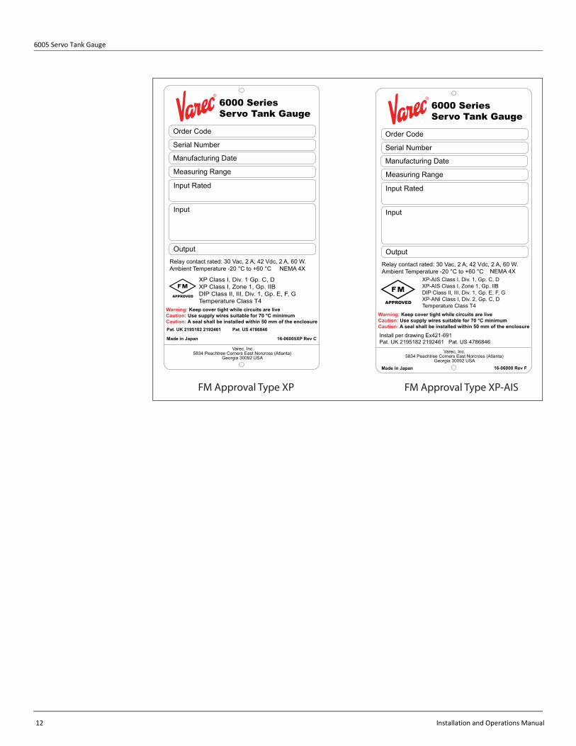
12 Installation and Operations Manual
XP Class I, Div. 1 Gp. C, D XP Class I, Zone 1, Gp. IIB DIP Class II, III, Div. 1, Gp. E, F, G Temperature Class T4
Made in Japan 16-06005XP Rev C
Order Code
Serial Number
Manufacturing Date
Measuring Range
Input Rated
Input
Output
6000 SeriesServo Tank Gauge
Relay contact rated: 30 Vac, 2 A; 42 Vdc, 2 A, 60 W.Ambient Temperature -20 °C to +60 °C NEMA 4X
Warning: Keep cover tight while circuits are liveCaution: Use supply wires suitable for 70 °C minimumCaution: A seal shall be installed within 50 mm of the enclosure
APPROVED
Pat. UK 2195182 2192461 Pat. US 4786846
Varec, Inc.5834 Peachtree Corners East Norcross (Atlanta)
Georgia 30092 USA
XP-AIS Class I, Div. 1, Gp. C, DXP-AIS Class I, Zone 1, Gp. IIBDIP Class II, III, Div. 1, Gp. E, F, GXP-ANI Class I, Div. 2, Gp. C, DTemperature Class T4
Install per drawing Ex421-691Pat. UK 2195182 2192461 Pat. US 4786846
Order Code
Serial Number
Manufacturing Date
Measuring Range
Input Rated
Input
Output
6000 SeriesServo Tank Gauge
Relay contact rated: 30 Vac, 2 A; 42 Vdc, 2 A, 60 W.Ambient Temperature -20 °C to +60 °C
APPROVED
NEMA 4X
Warning: Keep cover tight while circuits are liveCaution: Use supply wires suitable for 70 °C minimumCaution: A seal shall be installed within 50 mm of the enclosure
16-06000 Rev FMade in Japan
Varec, Inc. 5834 Peachtree Corners East Norcross (Atlanta)
Georgia 30092 USA
FM Approval Type XP FM Approval Type XP-AIS

Chapter 3 - Identification
Varec, Inc. 13
Figure 3-1: 6005 STG Product Labels
Scope of Delivery Caution It is essential to follow the instructions concerning the unpacking, transport and storage of measuring instruments given in section , "Incoming Acceptance, Transport, and Storage" on page 7.
The scope of delivery consists of:
• Assembled instrument
Accompanying documentation:
• Installation and Operations (this manual)• Safety Instructions (APT092GVAExxxx)• Functional Safety Manual (APT221GVAExxxx), supplied with 4-20mA and overspill
prevention relay output
Made in Japan 16-06000NA Rev A
Order Code
Serial Number
Manufacturing Date
Measuring Range
Input Rated
Input
Output
6000 SeriesServo Tank Gauge
Relay contact rated: 30 Vac, 2 A; 42 Vdc, 2 A, 60 W.Ambient Temperature -20 °C to +60 °C
NEMA 4X IP67
Warning: Keep cover tight while circuits are liveCaution: Use supply wires suitable for 70 °C minimum
Pat. UK 2195182 2192461 Pat. US 4786846
Varec, Inc.5834 Peachtree Corners East Norcross (Atlanta)
Georgia 30092 USA
Varec, Inc. 5834 Peachtree Corners East Norcross (Atlanta)
Georgia 30092 USA
Order Code
Serial Number
Manufacturing Date
Measuring Range
Input Rated
Input
Output
6000 SeriesServo Tank Gauge
Relay contact rated: 30 Vac, 2 A; 42 Vdc, 2 A, 60 W.Ambient Temperature -20 °C to +60 °
Warning: Keep cover tight while circuits are liveCaution: Use supply wires suitable for 70 °C minimumCaution: A seal shall be installed within 50 mm of the enclosure
EX16-06000CSA Rev BMade in Japan
NEMA 4X
Exd IIB T4Class I, Div. 1 Gp. C,DClass II, Div. 1 Gp. E,F,G; Class III
Install per drawing Ex540-853Pat. UK 2195182 2192461 Pat. US 4786846
216422
CSA Approval Type Ex d Weatherproof NMEA 4X / IP67 only Approval
6005 Servo Tank Gauge
14 Installation and Operations Manual
Certificates and Approvals
CE mark, Declaration of Conformity
The device is designed to meet state-of-the-art safety requirements, has been tested and left the factory in a condition in which it is safe to operate. The device complies with the applicable standards and regulations as listed in the EC declaration of conformity and thus complies with the statutory requirements of the EC directives. Varec, Inc. confirms the successful testing of the device by affixing to it the CE mark.
Varec, Inc. 15
Chapter 4
Mounting The following installation procedures are available for the 6005 STG.
• Mounting without guide system.• Mounting with stilling well (also called pipe)• Mounting with guide wire
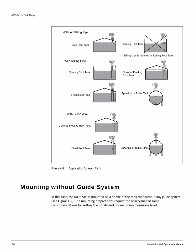
Application Drawing for Tank Mounting with stilling well or guide wire is required for the following applications:
• Floating roof tank• Covered floating roof tank• Tank with strong agitator or heavy turbulence
Mounting without any guide system covers all cases that are not listed above.
Figure 4-1 shows examples of applications (with and without stilling well mounting, with guide wire mounting)
6005 Servo Tank Gauge
16 Installation and Operations Manual
Figure 4-1: Application for each Tank
Mounting without Guide System In this case, the 6005 STG is mounted on a nozzle of the tank roof without any guide system (see Figure 4-2). The mounting preparations require the observance of some recommendations for setting the nozzle and the minimum measuring level.
Floating Roof Tank
Fixed Roof Tank
Without Stilling Pipe
Fixed Roof Tank
With Stilling Pipe
Covered FloatingRoof Tank
Spherical or Bullet Tank
With Guide Wire
Fixed Roof Tank Spherical or Bullet Tank
Floating Roof Tank
Stilling pipe is required in floating Roof Tank.
Covered Floating Roof Tank

Chapter 4 - Mounting
Varec, Inc. 17
Figure 4-2: Mounting Without Guide System
Mounting with Stilling Well
Pipe diameter
The pipe diameter that is required to protect the measuring wire without disturbing its operation depends on the tank height. The pipe could either be constant diameter, or thinner at its upper part and thicker at its lower part. Figure 4-3 shows two examples of the latter case, namely an asymmetric pipe and a concentric pipe.
Displacerd
D1
6005 STG

6005 Servo Tank Gauge
18 Installation and Operations Manual
Figure 4-3: Mounting with Stilling Well: Asymmetric Pipe and Connection Pipe
Valve
Asymmetric Pipe ConcentricPipe
Displacer
Maintenance Chamber
6005 STG
Asymmetric Pipe (Side View) Concentric Pipe (Front View)
6005 STG

Chapter 4 - Mounting
Varec, Inc. 19
Note This valve is necessary when mounting the 6005 STG onto pressurized liquid tanks. The 6005 STG must be mounted on the asymmetric pipe in the direction shown above.
To calculate the required pipe diameters, the formula below should be used.
The variables and constants have the following meanings:
Table 1: Meaning of Variables and Constants Used in Formula to Calculate Pipe Diameters
• Upper diameter
D1 > d + 10 mm
where D1 > 3" should be fulfilled.
• Lower diameter- Asymmetric pipe
D2 > d+ eL + 2vL+ 10mm
- Concentric pipe
D2 > d + 2eL + 2vL + 10mm
Variable/Constant Meaning
D1 Inner diameter of the upper part of the pipe
D2 Inner diameter of the lower part of the pipe
L Length of the pipe (from the flange of the 6005 STG to bottom of the stilling well) ...meters
v Deviation of the pipe from the vertical per length (mm/m)
d Diameter of the displacer
e Lateral shift of the displacer per length due to the groove of the wire drum (max.33 mm)
Feature: 070 Measuring Range/Material/Diameter of Wire
e = Lateral Shift (mm)
C 0-28m: SUS316L, 0.15mm 0.37
H 0-16m: PFA>SUS316, 0.4mm 0.40
K 0-16m: Alloy C, 0.2mm 0.47
L 0-36m: SUS316L, 0.15mm 0.33
M 0-22m: Alloy C, 0.2mm 0.47
N 0-47m: SUS316L, 0.15mm 0.30
6005 Servo Tank Gauge
20 Installation and Operations Manual
Recommendations for Mounting
Note Observe the following recommendations for mounting with stilling well:
• Keep the pipe connection welds smooth.• While drilling holes into the pipe, keep the interior surface of the holes clear of metal
chips and burrs.• Coat or paint the interior surface of the pipe to avoid rust.• Keep the pipe as perfectly vertical as possible. Check this by a plumb.• Install the asymmetric pipe under the valve and fit the centers of the 6005 STG and
the valve.• Set the center of the lower part of the asymmetric pipe to the direction of the
displacer motion.• Observe recommendations as per API MPMS chapter 3.1B.• Confirm grounding between 6005 STG and tank nozzle.
Mounting with Guide WireIt is also possible to guide the displacer via guide wires to prevent lateral motion.
Guide Wire Installation
• Secure guide wire to wire hook.• Secure springs to reducer plate (see Figure 4-4).• Temporarily fix the STG so that the springs are located on the outside of reducer
plate and execute weight calibration.• Fix the STG to reducer plate.• Put displacer ring through the guide wires and set the displacer so that the
marking ring is located at the reference position.

Chapter 4 - Mounting
Varec, Inc. 21
Figure 4-4: Mounting with Guide Wire
Chamber for maintenance
Calibration Chamber
Ø50 mm Displacer (or Ø70mm, Ø110mm)
Tank Bottom
Welding
Anchor hook plate
172
30
0
Ø150
CALIBRATION CHAMBER (for Low pressure)
Flange
Flange
Measuring wire
Tank
Guide wire
Sleeve
Spring
Reducer plate
Spring Sleeve
Guide wireSleeve
Crimp tool
Flange 6”
100mm
Reference position
Marking ring
*1
*1Reducer plate : for low pressure, 6mmReducer flange : for high pressure, (depending on standard)
6005 STG

6005 Servo Tank Gauge
22 Installation and Operations Manual
Weight Calibration Method for Guide Wire Installation
1. Temporarily fix the 6005 STG so that the 6005 STG is located at the outside of the reducer plate in order to perform weight calibration.
2. Replace the measuring wire to an appropriate length. During standard weight calibration, the displacer moves up until it touches the mechanical stop in the housing. After weight calibration is finished the displacer will stop 70mm (configurable, GVH378) below the mechanical stop. This is the Refer-ence Position.
Figure 4-5: Weight Calibration for the 6005 STG with Guide Wire
3. During this special weight calibration procedure the guide rings of the displacer will touch the bottom face of the flange.
4. The displacer will then go down 70mm and stop. The STG remembers this as the Reference Position, and weight table calibration resumes.
5. When weight calibration is complete, return the STG back to its normal mounting position on the tank nozzle. This completes the weight calibration procedure.
70mm
Referenceposition
Chapter 4 - Mounting
Varec, Inc. 23
Tank Type
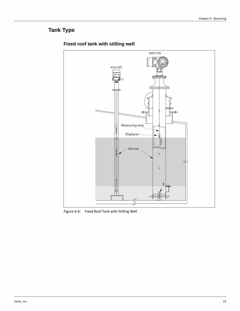
Fixed roof tank with stilling well
Figure 4-6: Fixed Roof Tank with Stilling Well
Measuring wire
Displacer
Still well
B
E - +
453x ATC
6005 STG

6005 Servo Tank Gauge
24 Installation and Operations Manual
High pressure tank with stilling well and ball valve
Figure 4-7: High Pressure Tank with Stilling Well and Ball Valve
E - +
Ball Valve
Reducer
Meas. Wire
Displacer
Stilling Well
6005 STG
453x ATC

Chapter 4 - Mounting
Varec, Inc. 25
Floating roof tank and /or covered floating roof Tank
Figure 4-8: Floating Roof Tank and/or Covered Floating Roof Tank
E - +
Measuring wire
Displacer
Still well
6005 STG
453x ATC

6005 Servo Tank Gauge
26 Installation and Operations Manual
Note When the STG is installed on a floating roof tank, be sure to use a stilling well.
Figure 4-9: Floating Roof Tank use with Stilling Well
E - +
Measuring wire
Displacer
6005 STG

Chapter 4 - Mounting
Varec, Inc. 27
High or Low Temperature Tank
When installing to a high or low temperature storage tank, heat or cold from the liquid or tank wall should not be emitted to the 6005 STG directly. For example, cover the tank with thermal insulation material and/or install an ambient temperature adjust pipe between the 6005 STG and the nozzle of the tank as shown in the figure below.
Figure 4-10: High or Low Temperature Mounting
Proservo
Wire
The temperature of the flange and the internal temperature of the drumcomponent:-20º (or -40º) ≤ T ≤ 60º C
Ambient temperatureadjust pipe (optional)
Thermal Insulation MaterialTank Wall
Displacer
High or Lowtemperatureliquid

6005 Servo Tank Gauge
28 Installation and Operations Manual
Mounting Preparations
Flange
The mounting flange should be prepared before mounting the 6005 STG to the tank. The flange size and the rating of the 6005 STG depend on the customer’s specifications.
Note Check the flange size of the 6005 STG.
Note Install the flange on the top of the tank. The flange’s deviation from the horizontal plane should not exceed +/- 1 deg.
Note For mounting the 6005 STG onto a longer nozzle, make sure that the displacer does not touch the interior surface because of the vertical inclination of the nozzle.
Figure 4-11: Allowable Inclination of the Mounting Flange
Mounting Nozzle
max. +1°max. -1°

Chapter 4 - Mounting
Varec, Inc. 29
Note If the STG is installed without a guide system, then consider the following recom-mendations:
• Set the mounting nozzle in the sector between 45 and 90 deg (or -45 and -90 deg.) apart from the inlet pipe of the tank. This will prevent heavy swing of the displacer caused by wave or turbulence of the inlet liquid.
• Set the mounting nozzle at least 500mm away from the tank wall. This will ensure that the measurement is not influenced by changes of the ambient temperature.
• Set the minimum measuring level at least 500mm above the top of the inlet pipe. This will protect the displacer from direct flow of the inlet liquid.
If it is not possible to install the 6005 STG in such place, then we recommend mounting with a guide system. Consult Varec for further information.
Figure 4-12: Recommended Setting of Mounting Nozzle and Minimum Measuring Level
Warning Before putting liquid into the tank, make sure that the flow from the inlet pipe cannot hit the displacer directly. When removing liquid from the tank, avoid suction of the displacer to the outlet pipe.
-90° 90°
-45° 45°
0°
InletPipe
MountingNozzle
MountingNozzle
Minimum Measuring Level
InletPipe

6005 Servo Tank Gauge
30 Installation and Operations Manual
Electrostatic ChargeNote If the liquid measured by the 6005 STG has a conductivity of less than 10-8 s/cm, it is quasi-nonconductive. In that case, we recommend to use a stilling well or guide wire made of conductive material. This will release the electrostatic charge on the liquid sur-face.
Installation for Wire Drum and Displacer The 6005 STG is delivered with 2 options for displacer mounting:
1. “All-in-one” with displacer mounted on the measuring wire. In this case, follow the instruc-tions for removing the packing, which are attached to the 6005 STG.
2. Displacer shipped separately. In this case, it is necessary to install the displacer on the measuring wire inside the 6005 STG.
In either case, follow the instructions below.
All-in-One
Remove all packing material before mounting the 6005 STG.
Packaging Material De-Installation Procedure
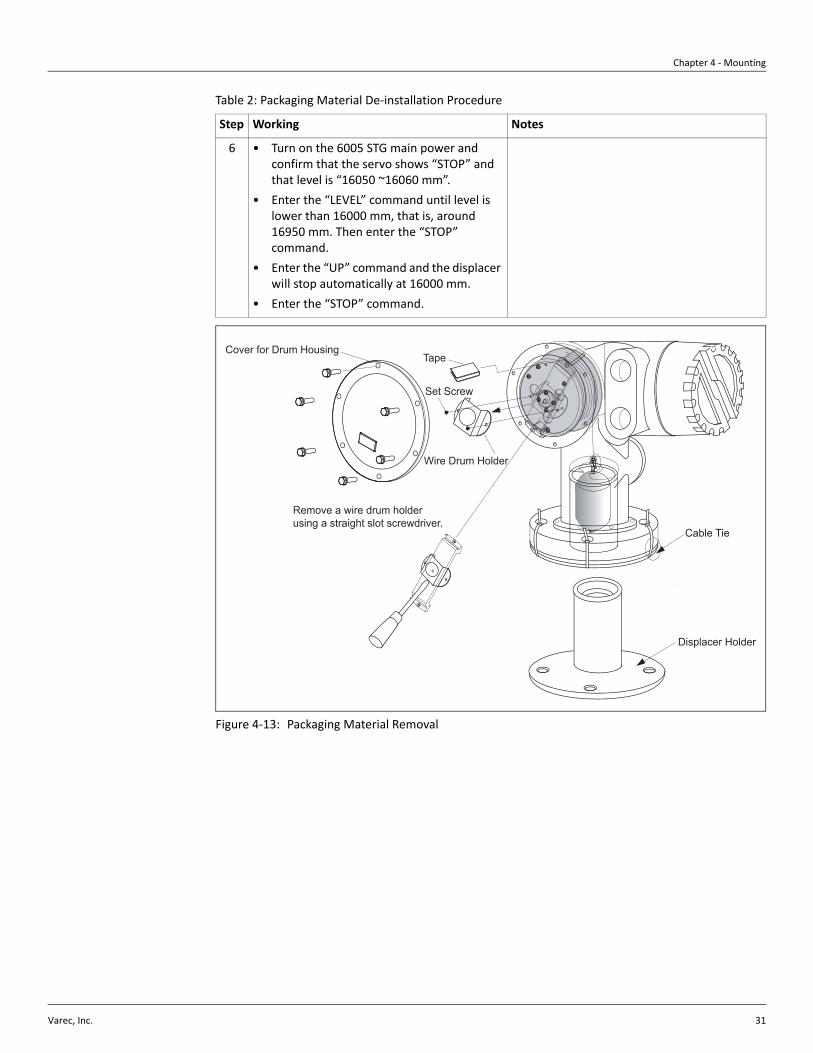
Table 2: Packaging Material De-installation Procedure
Step Working Notes
1 • Hold the gauge with the flange horizontal• Cut the cable ties.• Remove displacer holder
• Do not tilt the gauge after removing displacer holder.
2 • Mount the 6005 STG on the nozzle. • Check that the measuring wire hangs vertically.
• Check that there are no kinks or any abnormality from calibration window.
3 • Remove the drum housing cover.• Loosen two screws on wire drum holder,
remove the holder. (see Figure 4-13 on page 31)
• Be careful not to lose the O-ring and the drum housing cover bolts and washers.
4 • Remove tape on wire drum slowly. • Remove the tape by hand to avoid damage to the wire drum.
• Make sure the measuring wire is wrapped so that it fits correctly in the grooves.
• If not, rewrap the wire so it fits correctly in the grooves.
5 • Install the drum housing cover • Check that the O-ring is fitted in groove.
Chapter 4 - Mounting
Varec, Inc. 31
Figure 4-13: Packaging Material Removal
6 • Turn on the 6005 STG main power and confirm that the servo shows “STOP” and that level is “16050 ~16060 mm”.
• Enter the “LEVEL” command until level is lower than 16000 mm, that is, around 16950 mm. Then enter the “STOP” command.
• Enter the “UP” command and the displacer will stop automatically at 16000 mm.
• Enter the “STOP” command.
Table 2: Packaging Material De-installation Procedure
Step Working Notes
Displacer Holder
Cable Tie
Tape
Wire Drum Holder
Set Screw
Remove a wire drum holder using a straight slot screwdriver.
Cover for Drum Housing
6005 Servo Tank Gauge
32 Installation and Operations Manual
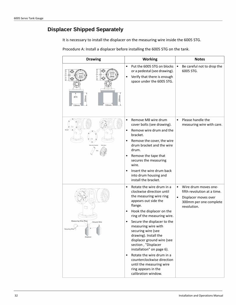
Displacer Shipped Separately
It is necessary to install the displacer on the measuring wire inside the 6005 STG.
Procedure A: Install a displacer before installing the 6005 STG on the tank.
Drawing Working Notes
• Put the 6005 STG on blocks or a pedestal (see drawing).
• Verify that there is enough space under the 6005 STG.
• Be careful not to drop the 6005 STG.
• Remove M8 wire drum cover bolts (see drawing).
• Remove wire drum and the bracket.
• Remove the cover, the wire drum bracket and the wire drum.
• Remove the tape that secures the measuring wire.
• Insert the wire drum back into drum housing and install the bracket.
• Please handle the measuring wire with care.
• Rotate the wire drum in a clockwise direction until the measuring wire ring appears out side the flange.
• Hook the displacer on the ring of the measuring wire.
• Secure the displacer to the measuring wire with securing wire (see drawing). Install the displacer ground wire (see section , "Displacer installation" on page 6).
• Rotate the wire drum in a counterclockwise direction until the measuring wire ring appears in the calibration window.
• Wire drum moves one-fifth revolution at a time.
• Displacer moves over 300mm per one complete revolution.
130mm
20
0m
mØ70
130mm
20
0m
m
Wire drumWire drum bracket
M6 bolt
Tape
Measuring Wire Ring
Securing Wire
Displacer
Ground Wire
Chapter 4 - Mounting
Varec, Inc. 33
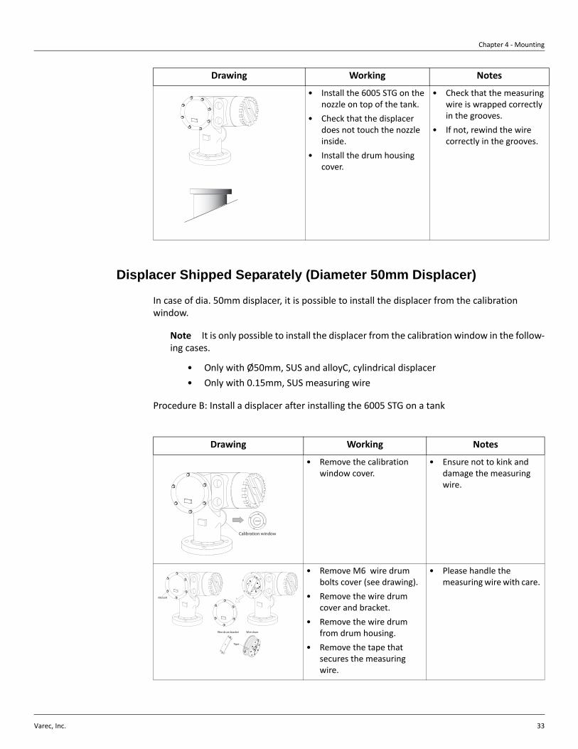
Displacer Shipped Separately (Diameter 50mm Displacer)
In case of dia. 50mm displacer, it is possible to install the displacer from the calibration window.
Note It is only possible to install the displacer from the calibration window in the follow-ing cases.
• Only with Ø50mm, SUS and alloyC, cylindrical displacer• Only with 0.15mm, SUS measuring wire
Procedure B: Install a displacer after installing the 6005 STG on a tank
• Install the 6005 STG on the nozzle on top of the tank.
• Check that the displacer does not touch the nozzle inside.
• Install the drum housing cover.
• Check that the measuring wire is wrapped correctly in the grooves.
• If not, rewind the wire correctly in the grooves.
Drawing Working Notes
Drawing Working Notes
• Remove the calibration window cover.
• Ensure not to kink and damage the measuring wire.
• Remove M6 wire drum bolts cover (see drawing).
• Remove the wire drum cover and bracket.
• Remove the wire drum from drum housing.
• Remove the tape that secures the measuring wire.
• Please handle the measuring wire with care.
Calibration window
Wire drumWire drum bracket
M6 bolt
Tape
6005 Servo Tank Gauge
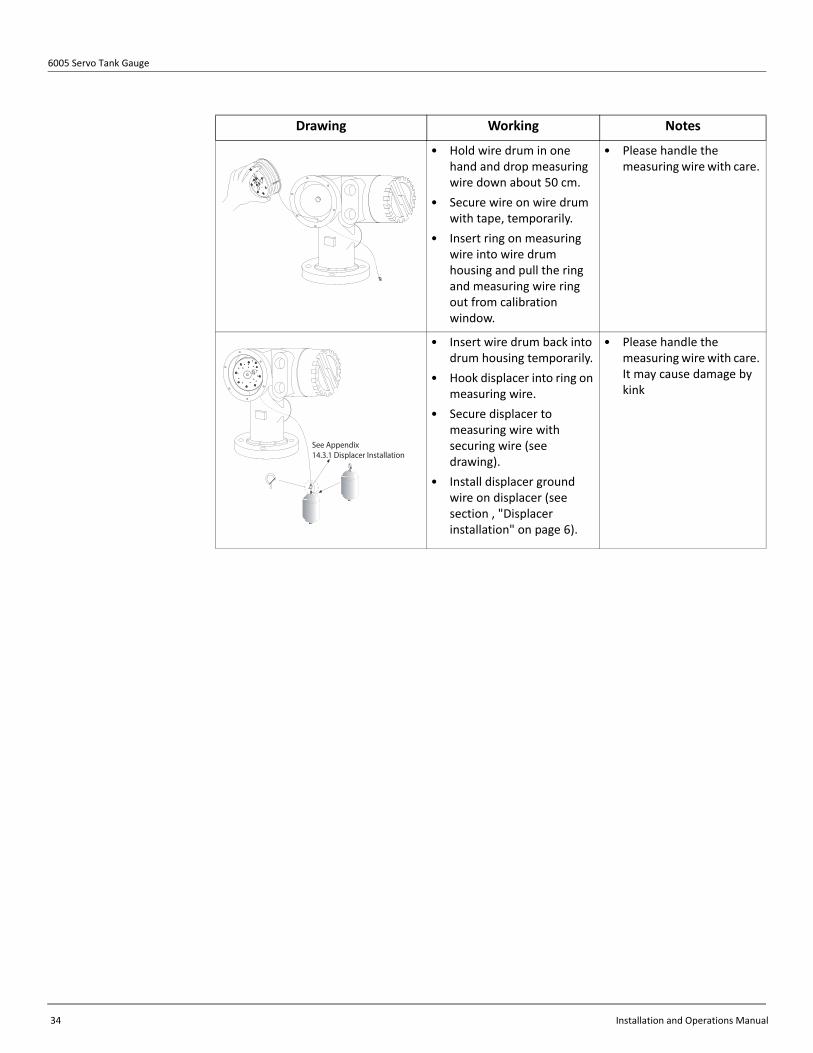
34 Installation and Operations Manual
• Hold wire drum in one hand and drop measuring wire down about 50 cm.
• Secure wire on wire drum with tape, temporarily.
• Insert ring on measuring wire into wire drum housing and pull the ring and measuring wire ring out from calibration window.
• Please handle the measuring wire with care.
• Insert wire drum back into drum housing temporarily.
• Hook displacer into ring on measuring wire.
• Secure displacer to measuring wire with securing wire (see drawing).
• Install displacer ground wire on displacer (see section , "Displacer installation" on page 6).
• Please handle the measuring wire with care. It may cause damage by kink
Drawing Working Notes
See Appendix
14.3.1 Displacer Installation

Chapter 4 - Mounting
Varec, Inc. 35
Drawing Working Notes
• Hold the wire drum in one had and the displacer in the other hand.
• Remove wire drum from wire drum housing and drop measuring wire down about 50 cm.
• Hold wire drum up and place displacer into calibration window
• Hold one hand (displacer) at center of calibration window.
• Hold other hand (wire drum) up and add tension to measuring wire so that the displacer does not drop down rapidly.
• Wire drum moves one-fifth revolution at a time.
• Displacer move over 300mm per one complete revolution.
• Carefully release the displacer.
• Remove tape on wire drum and insert wire drum into drum housing.
• Install the wire drum bracket.
• Rotate wire drum with your hand a few times and check that displacer does not touch the inside of the nozzle.
• Rotate the wire drum in a counter-clockwise direction until the measuring wire ring appears in the calibration window.
• Install the wire drum housing cover and calibration window cover.
• Check that the measuring wire is wrapped correctly in the grooves.
• If not, rewind the wire correctly in the grooves.
Table 3: Procedure B: Install a Displacer after Installing the 6005 STG on a Tank

6005 Servo Tank Gauge
36 Installation and Operations Manual

Varec, Inc. 37
Chapter 5
Wiring
Wiring Connection The electrical connections of the 6005 STG are shown in Figure 5-1 on page 38 through Figure 5-6 on page 43.
Note The power supply cable should have the following specifications:
• PVC, PE, or equivalently isolated• 600 V insulation voltage or equivalent• Temperature rating 80 or higher
Note The size of the core will be defined by core resistance, voltage drop, and required power consumption. The maximum power consumption of the 6005 STG is 50 VA / 50 W.
Caution Connect the ground line to the ground terminal inside or outside the terminal box. Use cable and wire of sufficient and appropriate size and length, to make a solid con-nection at each required terminal.
Warning Do not stretch cable or wires. Doing so may lead to failure, loss of function, and/or damage to the device and facility.
Warning Trim cable and wire to appropriate length. Do not leave excess cable and wire in the electrical compartment. Doing so may lead to failure, loss of function, and /or damage to the device and facility.
Terminal AssignmentThe terminal assignments appear on the following pages.

6005 Servo Tank Gauge
38 Installation and Operations Manual
Ex d IIB, Output 1: V1, RS485, HART, Enraf BPM, MODBUS
Figure 5-1: Electrical Connection of the 6005 STG
N6005- X X X X X X X X X X X
056GQS
NPFAGH
Order Code Example
14AL4 COM
18CTR2
20OT1+
22OT2+
AL415
CTR117
N.C.19
OT1-21
OT2-23
48AL1
10AL2
12AL3
AL313
AL211
AL19
RCB/-7 5
6RCA/+
24
NRF+
A
25
NRF-
B
26
b
123
ARSL
ARSG
ARS
POWLPOWNPOWGARSLARSGARSN
NRF+NRF-RC A/+
RCB/-ALM1/OSPALM1/OSPALM2/OSPALM2/OSPALM3
123L
NG
AC Power Supply
242526
+-
+-+-
ALM3
141516171819
202122
+-+-
23
456789
10111213
ALM4ALM4COMCTR1CTR2
OUT 1+OUT 1-OUT 2+OUT 2-
TMPA /NMT+TMPB/NMT-TMP b
FuseF1
L
NG
Lightning Arrester
N4560 or Non IS HART Devices
V1, Modbus RS485, HART, Enraf BPM
Alarm Contact (Option)
External contact Input(Option)
Alarm Contact (Option)
DC4...20mA Output (Option)
DC4...20mA Output (Option)
N453x or HARTDevice (NonIS)
Ground
or Pt100 ohm Input
N
16
LNGND
StopHoistCommon
NMT+NMT-
Alarm Contact (Option)
Alarm Contact (Option)
Chapter 5 - Wiring
Varec, Inc. 39
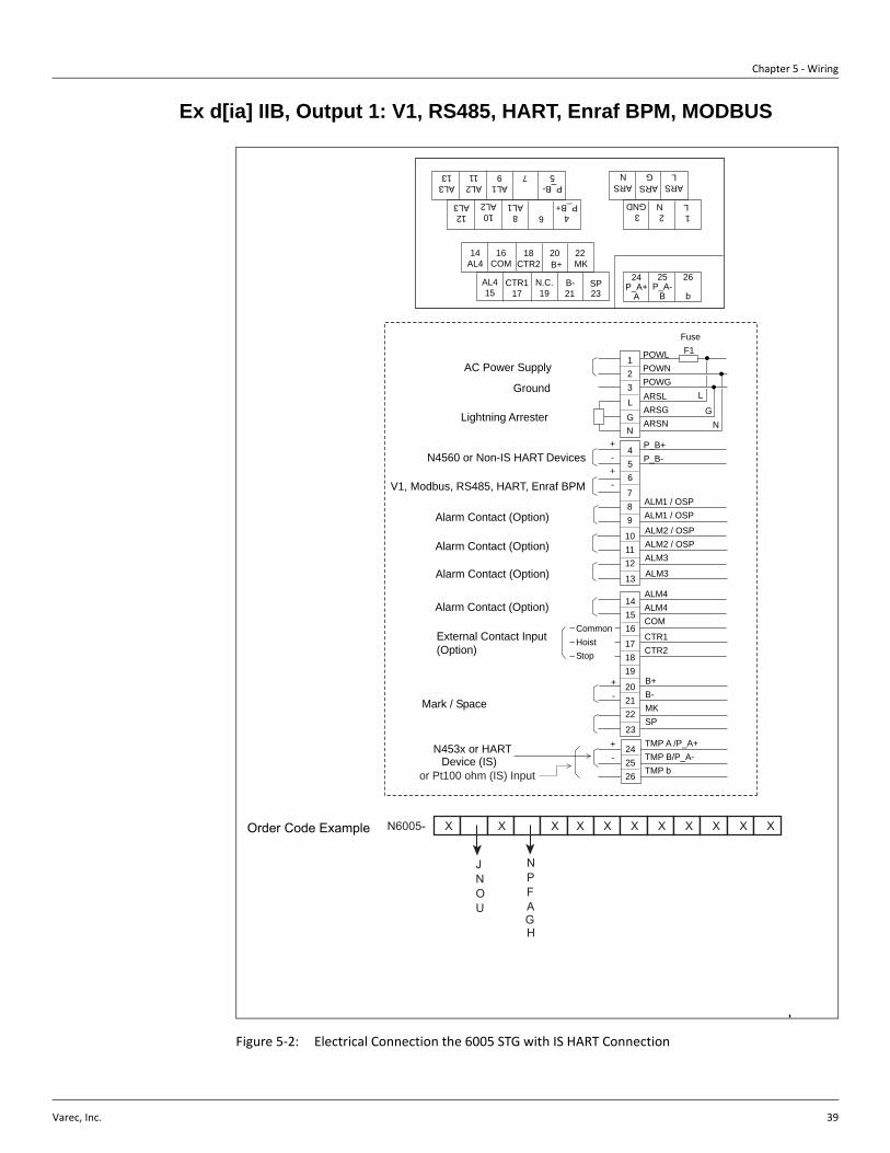
Ex d[ia] IIB, Output 1: V1, RS485, HART, Enraf BPM, MODBUS
Figure 5-2: Electrical Connection the 6005 STG with IS HART Connection
Order Code Example N6005- X X X X X X X X X X X
JNO U
NPFAGH
14AL4 COM
18CTR2
20B+
22MK
AL415
CTR117
N.C.19
B-21
SP23
4P_B+
8AL1
10AL2
12AL3
AL313
AL211
AL19 7
P_B-5
6
24P_A+
A
25P_A-
B
26
b
123
ARSL
ARSG
ARSN
POWLPOWNPOWGARSLARSGARSN
P_B+P_B-
ALM1 / OSPALM1 / OSP
ALM2 / OSPALM2 / OSPALM3
123L
NG
AC Power Supply
242526
+-
+-+-
ALM3
141516
171819
202122
+-
23
456
789
101112
13
ALM4ALM4COM
CTR1CTR2
B+B-MKSP
TMP A /P_A+TMP B/P_A-TMP b
FuseF1
L
NGLightning Arrester
N4560 or Non-IS HART Devices
Alarm Contact (Option)
Alarm Contact (Option)
Alarm Contact (Option)
External Contact Input(Option)
Alarm Contact (Option)
CommonHoistStop
Ground
N453x or HARTDevice (IS)
Mark / Space
V1, Modbus, RS485, HART, Enraf BPM
or Pt100 ohm (IS) Input
N LGND
16
6005 Servo Tank Gauge
40 Installation and Operations Manual
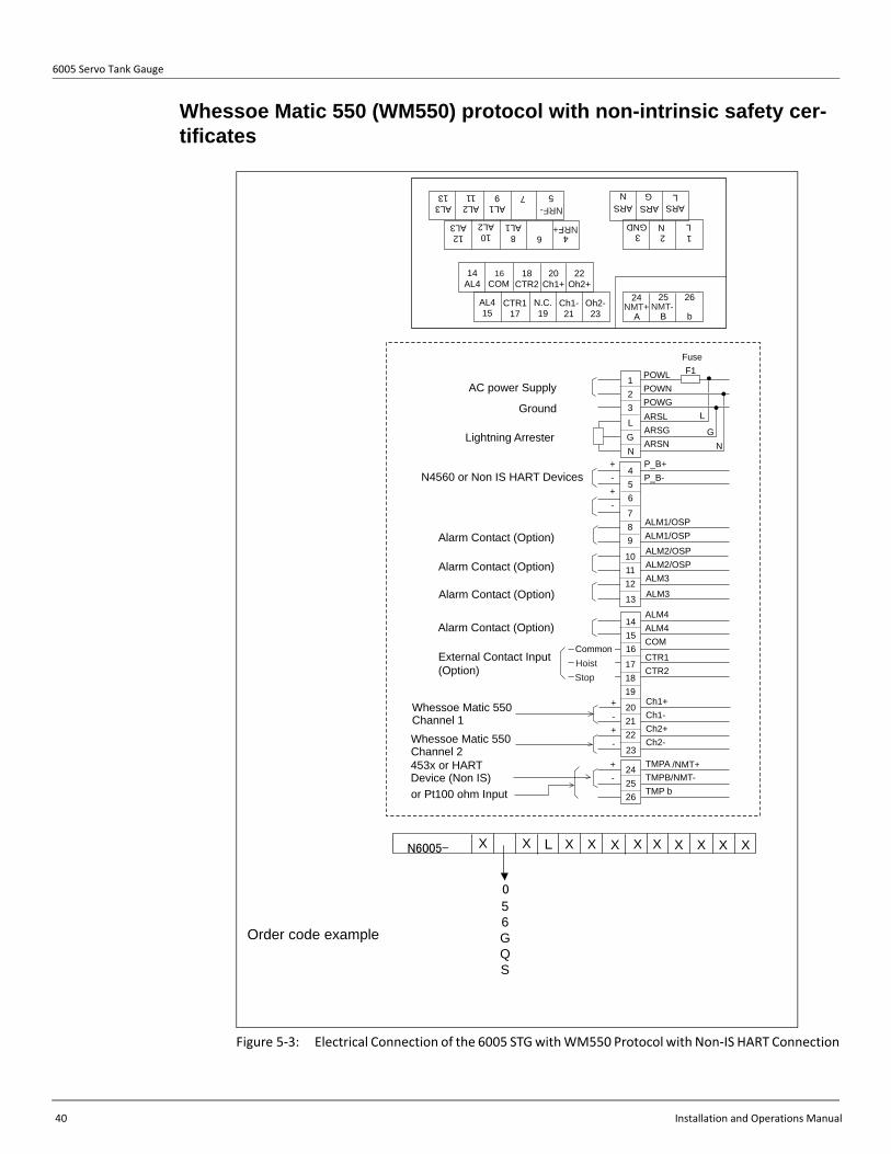
Whessoe Matic 550 (WM550) protocol with non-intrinsic safety cer-tificates
Figure 5-3: Electrical Connection of the 6005 STG with WM550 Protocol with Non-IS HART Connection
Order code example
X X X X X X X X X X X
56GQS
LN6005-
0
14AL4 COM
18CTR2
20Ch1+
22Oh2+
AL415
CTR117
N.C.19
Ch1-21
Oh2-23
48AL1
10AL2
12AL3
AL313
AL211
AL19 7 5
6
24
A
25
B
26
b
123
ARSL
ARSG
ARSN
POWLPOWNPOWGARSLARSGARSN
ALM1/OSPALM1/OSP
ALM2/OSPALM2/OSPALM3
123L
NG
AC power Supply
242526
+-
+-+-
ALM3
141516
171819
202122
+-+-
23
456
789
101112
13
ALM4ALM4COM
CTR1CTR2
Ch1+Ch1-Ch2+Ch2-
TMPA /NMT+TMPB/NMT-TMP b
FuseF1
L
NGLightning Arrester
N4560 or Non IS HART Devices
Alarm Contact (Option)
Alarm Contact (Option)
Alarm Contact (Option)
External Contact Input(Option)
Alarm Contact (Option)
Whessoe Matic 550Channel 1Whessoe Matic 550Channel 2
Common
Ground
or Pt100 ohm Input
453x or HARTDevice (Non IS)
LNGND
NMT+ NMT-
StopHoist
16
P_B+P_B-
NRF+
NRF-
Chapter 5 - Wiring
Varec, Inc. 41
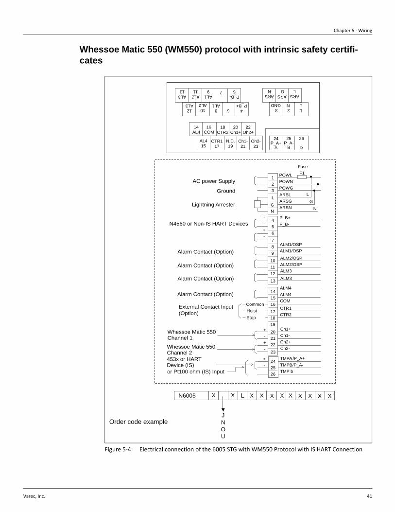
Whessoe Matic 550 (WM550) protocol with intrinsic safety certifi-cates
Figure 5-4: Electrical connection of the 6005 STG with WM550 Protocol with IS HART Connection
Order code example
14AL4 COM
18CTR2
20Ch1+
22Oh2+
AL415
CTR117
N.C.19
Ch1-21
Oh2-23
4P_B+
8AL1
10AL2
12AL3
AL313
AL211
AL19 7
P_B-5
6
24P_A+
A
25P_A-
B
26
b
123
ARSL
ARSG
ARSN
POWLPOWNPOWGARSLARSGARSN
P_B+P_B-
ALM1/OSPALM1/OSP
ALM2/OSPALM2/OSPALM3
123L
NG
AC power Supply
242526
+-
+-+-
ALM3
141516
171819
202122
+-+-
23
456
789
101112
13
ALM4ALM4COM
CTR1CTR2
Ch1+Ch1-Ch2+Ch2-
TMPA/P_A+TMPB/P_A-TMP b
FuseF1
L
NGLightning Arrester
Alarm Contact (Option)
Alarm Contact (Option)
Alarm Contact (Option)
External Contact Input(Option)
Alarm Contact (Option)
Whessoe Matic 550Channel 1Whessoe Matic 550Channel 2
Common
Ground
453x or HARTDevice (IS)
N4560 or Non-IS HART Devices
Pt100 ohm (IS) Input
LGND N
16
or
StopHoist
N6005 X X X X X X X X X X X
JNOU
L
6005 Servo Tank Gauge
42 Installation and Operations Manual
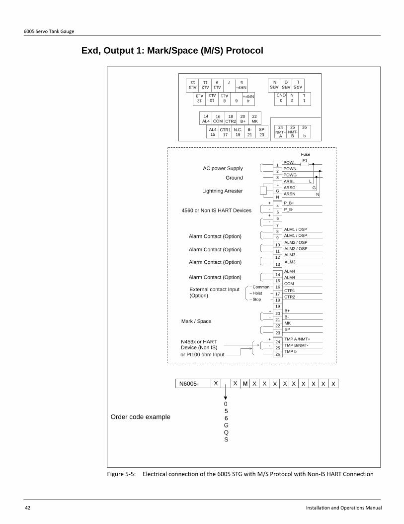
Exd, Output 1: Mark/Space (M/S) Protocol
Figure 5-5: Electrical connection of the 6005 STG with M/S Protocol with Non-IS HART Connection
Order code example
N6005- X X X X X X X X X X X
56GQS
M
0
14AL4 COM
18CTR2
20B+
22MK
AL415
CTR117
N.C.19
B-21
SP23
48AL1
10AL2
12AL3
AL313
AL211
AL19 7 5
6
24
A
25
B
26
b
123
ARSL
ARSG
ARSN
POWLPOWNPOWGARSLARSGARSN
ALM1 / OSP ALM1 / OSP
ALM2 / OSPALM2 / OSPALM3
123L
NG
AC power Supply
242526
+-
+-+-
ALM3
141516
171819
202122
+-
23
456
789
101112
13
ALM4ALM4COM
CTR1CTR2
B+B-MKSP
TMP A /NMT+TMP B/NMT-TMP b
FuseF1
L
NG
Lightning Arrester
4560 or Non IS HART Devices
Alarm Contact (Option)
Alarm Contact (Option)
Alarm Contact (Option)
External contact Input(Option)
Alarm Contact (Option)
CommonHoistStop
Ground
N453x or HARTDevice (Non IS)
Mark / Space
or Pt100 ohm Input
NMT+ NMT-
LGND N
16
P_B+P_B-
NRF+
NRF-

Chapter 5 - Wiring
Varec, Inc. 43
Exd [ia], Output 1: Mark/Space (M/S) Protocol
Figure 5-6: Electrical connection of the 6005 STG with M/S Protocol with IS HART connection
14AL4 COM
18CTR2
20B+
22MK
AL415
CTR117
N.C.19
B-21
SP23
4P_B+
8AL1
10AL2
12AL3
AL313
AL211
AL19 7
P_B-5
6
24P_A+
A
25P_A-
B
26
b
123
ARSL
ARSG
ARSN
POWLPOWNPOWGARSLARSGARSN
P_B+P_B-
ALM1 / OSPALM1 / OSP
ALM2 / OSPALM2 / OSPALM3
123L
NG
AC power supply
242526
+-
+-+-
ALM3
141516
171819
202122
+-
23
456
789
101112
13
ALM4ALM4COM
CTR1CTR2
B+B-MKSP
TMP A /P_A+TMP B/P_A-TMP b
fuseF1
L
NGLightning arrester
4560 or Non-IS HART Devices
Alarm Contact (option)
Alarm Contact (option)
Alarm Contact (option)
External contact input(option)
Alarm Contact (option)
CommonHoistStop
Ground
Devices(IS)
Mark / Space
or Pt100 ohm (IS) input
N LGND
16
453x or HART
N600- X X M X X X X X X X X X
JNOU
Order Code Example

6005 Servo Tank Gauge
44 Installation and Operations Manual
Table 1 contains the logic for use with the external contact input (Hoist-CTR1)(Stop-CTR2).
Table 1: Logic for use with the External Contact Input (Hoist-CTR1)(Stop-CTR2)
Input and Output
Input
• Contact Switch• HART • Pt 100
Output
• V1• WM550• M/S• ENRAF BPM• MODBUS• HART• ANALOG 4-20mA• Overspill prevention (OSP)
Warning The cable used for input and/or output must be more than 24 AWG or larger, and must be screened or steel armored. A twisted pair is required for the HART and/or RS 485 signal.
Warning Two or three cores for mains, two cores for digital output, and two cores for HART input are normally used for the cabling of the 6005 STG. The instrument has maximum of four cable entries.
Warning Before placing an order for the 6005 STG, please check the cable size and the number of cables.
Cable gland
If all the cable entries are not used, then take out unnecessary glands and install a threaded plug to prevent intrusion of water.
Unused cable entries must be sealed. Refer to Safety Instruction APT092GVAExxxx.
CTR 1 CTR 2 OPERATION
OFF OFF LEVEL
ON OFF HOIST
OFF ON STOP
ON ON INTERFACE

Chapter 5 - Wiring
Varec, Inc. 45
Temperature Input System There are two types of temperature input method and two types of Ex protection system as Ex d or Ex [ia] in the 6005 STG.
Ex d HART input
These 6005 STGs have Ex d HART input to communicate with Ex d 453x series temperature sensor or auxiliary Ex d HART sensor.
Figure 5-7: Ex d HART Input
Ex d Pt100 Spot Temperature Input
These 6005 STGs have Ex d Pt100 temperature input connected directly from Ex d Pt100 sensor and Ex d HART input to communicate with auxiliary Ex d HART sensor.
26
4
24
25
J3
1A
1
3
5
J1
1B
Power
Module
POW
Ex d
4560
453x
Ex d
Ex d
HART
TCB CPU moduleTerminal module
HART
Sensor
Ex d
HART
Sensor
Ex d
5
6005 Servo Tank Gauge
46 Installation and Operations Manual
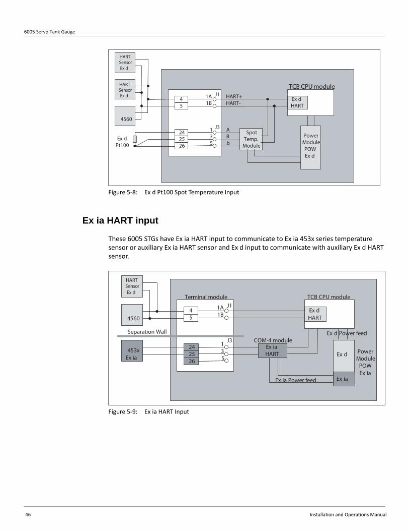
Figure 5-8: Ex d Pt100 Spot Temperature Input
Ex ia HART input
These 6005 STGs have Ex ia HART input to communicate to Ex ia 453x series temperature sensor or auxiliary Ex ia HART sensor and Ex d input to communicate with auxiliary Ex d HART sensor.
Figure 5-9: Ex ia HART Input
26
4
5
24
25
J3
1A
1
3
5
J1
1B
Spot
Temp.
Module
A
B
b
Ex d
HART
HART+
HART-
TCB CPU module
4560
Ex d
Pt100
Power
Module
POW
Ex d
HART
Sensor
Ex d
HART
Sensor
Ex d
26
4
5
24
25
J3
1A
1
3
5
J1
1B
Power
Module
POW
Ex ia
4560
453x
Ex ia
Ex d
HART
TCB CPU moduleTerminal module
Separation Wall
Ex ia
HART
COM-4 module
Ex iaEx ia Power feed
Ex d Power feed
Ex d
HART
Sensor
Ex d

Chapter 5 - Wiring
Varec, Inc. 47
Ex ia Pt100 Spot Temperature Input
These 6005 STGs have Ex ia Pt100 temperature input connected directly from Ex ia Pt100 sensor and Ex d HART input to communicate with auxiliary Ex d HART sensor.
Figure 5-10: Ex ia Pt100 Spot Temperature Input
26
4
5
24
25
J3
1A
1
3
5
J1
1B
Spot
Temp.
Module
A
B
b
HART+
HART-
TCB -4 CPU module
4560
Ex ia
Pt 100 Power
Module
POW
Ex ia
Separation Wall
Ex ia
Ex ia
Ex ia Power feed
Ex d Power feed
Ex d
HART
Sensor
Ex d
HART
Sensor
Ex d
Ex d
HART
Plastic
case
Ex ia
HART

6005 Servo Tank Gauge
48 Installation and Operations Manual

Varec, Inc. 49
Chapter 6
Operation
Touch Control and Programming Matrix
Display and Operating Elements
Display
During normal operation, the 6005 STG has an illuminated LCD that shows the level, the temperature, and the status of the device on the “HOME” position.
For the display of the other data and the programming of the parameters for operation, the 6005 STG uses a convenient programming matrix.
Operating Elements
The 6005 STG is operated by three visual operating elements, namely the keys “E”, “+”, and “-”. They are actuated when the appropriate field on the protective glass of the front is touched with the finger (“touch control”). The corresponding transmitting and receiving diodes are not affected by external influences, e.g. direct sunlight. The software and hardware installed in the 6005 STG rule out any malfunction that may be caused in this way. Even in explosive hazardous areas, the explosion-proof housing of the touch control ensures a safe access to the data.
Figure 6-1: Display
Illuminated LCD
3 Optical Operating Elements "Touch Control"
Infrared Receiving Diode
Infrared TransmittingDiode
LEVELU-D
0.0°C
6005 Servo Tank Gauge
50 Installation and Operations Manual
Functions of the Operating Elements
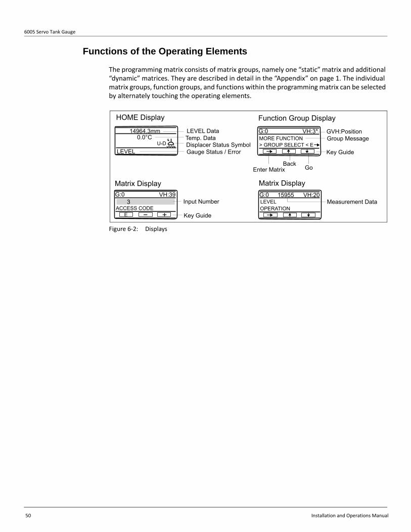
The programming matrix consists of matrix groups, namely one “static” matrix and additional “dynamic” matrices. They are described in detail in the “Appendix” on page 1. The individual matrix groups, function groups, and functions within the programming matrix can be selected by alternately touching the operating elements.
Figure 6-2: Displays
LEVELU-D
0.0°CLEVEL DataTemp. DataDisplacer Status SymbolGauge Status / Error
MORE FUNCTIONGVH:PositionGroup Message
Key Guide
G:0 VH:3*
> GROUP SELECT < E
Enter Matrix GoBack
HOME Display Function Group Display
Input Number
Key Guide
G:0 VH:39
ACCESS CODE3
E - +
Measurement Data G:0 VH:20
OPERATION
15955LEVEL
Matrix Display Matrix Display

Chapter 6 - Operation
Varec, Inc. 51
Matrix Construction
Figure 6-3: Matrix Construction
0 1 2 3 4 5 6 7 8 9 0 1 2 3 4 5 6 7 8 9Measured Value 1 0 Measured Value 1 0Measured Value 2 1 Measured Value 2 1Operation 2 Operation 2More Function 3 Calibration More Function 3 Device DataLevel Data 4 Contact Output 4Calibration 5 Analog Out 5Adjustment 6 parts Data 6Auto Wire Calib. 7 Input Signal 7Auto Calib. Displ. 8 Communication 8Display 9 Status 9
0 1 2 3 4 5 6 7 8 9 0 1 2 3 4 5 6 7 8 9Measured Value 1 0 Measured Value 1 0Measured Value 2 1 Measured Value 2 1Operation 2 Operation 2More Function 3 Service More Function 3 Temperature
4 TemperatureData 4
Gauge data 5 Element Temp. 5System Data 6 Element Position 6Service 7 NMT Adjustment 7Sensor Value 8 Set Data NMT 8Sensor Data 9 Device Data 9
0 1 2 3 4 5 6 7 8 9 0 1 2 3 4 5 6 7 8 9Measured Value 1 0 Measured Value 1 0Measured Value 2 1 Measured Value 2 1Operation 2 Operation 2More Function 3 HART Dev (1) More Function 3 HART Dev (2)Measured Value 4 Measured Value 4P.V. Setting 5 P.V. Setting 5Sensor Specific 6 Sensor Specific 6Alarm 7 Alarm 7Self Diagnostic 8 Self Diagnostic 8Device Data 9 Device Data 9
0 1 2 3 4 5 6 7 8 9 0 1 2 3 4 5 6 7 8 9Measured Value 1 0 Measured Value 1 0Measured Value 2 1 Measured Value 2 1Operation 2 Operation 2More Function 3 Adjust Sensor More Function 3 Tank ProfileAdjust Sensor 4 Profile Operation 4HART Error Rate 5 Status/Data 5Unit 6 Density 1-10 6HART Line 7 Density 11-16 7Interface Adjust 8 Position 1-10 8
9 Position 11-16 9
0 1 2 3 4 5 6 7 8 9Measured Value 1 0 Static Matrix Dynamic MatrixMeasured Value 2 1Operation 2More Function 3 Interface Profile
4Status/Data 5Density 1-10 6Density 11-16 7Position 1-10 8Position 11-16 9
Meas. Wire &Drum

6005 Servo Tank Gauge
52 Installation and Operations Manual
Table 1: Matrix Construction Keys and Functions
The LCD will return to the HOME position if no key is touched for more than 10 min. Digits are incremented or decremented by + or -, respectively. If the user touches + or - continuously, then the minimum digit will change first. After one cycle of the minimum, the second minimum will change. After one cycle of the second follows the third minimum, and so on. If the user removes their finger from the touch control, then the procedure will start again from the minimum digit (Analogy of mechanical counter).
Figure 6-4: Selection Matrix Groups, Function Groups, and Functions with Programming Matrix
Key Functions
• Access to the programming matrix (touch the key for more than 3 sec.)• Return to the HOME position (touch the key for more than 3 sec.)• Moving horizontally within a function group to select functions.• Saving parameters or access code.
• Moving vertically to select function groups• Selecting or setting parameters• Setting access code+ -
4
5
6
7
8
9
4
5
6
7
8
9
H
V
LCD ( HOME position)
If you touch on the matrix for 3 sec. or longer, you will return to the HOME position.
1 CALIBRATION
3 SERVICE4 TEMPERATURE5 HART DEVICE (1)6 HART DEVICE (2)7 ADJ. SENSOR8 TANK PROFILE9 INTERFACE PROFILE
0 1 2 3 4 5 6 7 8 9
0
1
2
3
4
5
6
7
8
9
4
4
4
4
7 ADJ. SENSOR
3 SERVICE
4 TEMPERATURE
5 HART DEVICE(1)
6 HART DEVICE(2)
> 3 s
2 DEVICE DATA
MATRIX OF G0 V3H0
4 2 DEVICE DATA
4 1 CALIBRATION
5
6
7
8
9
5
5
5
5
5
6
6
6
6
6
7
7
7
7
7
8
8
8
8
8
9
9
9
9
9
If you touch any"E" on the matrixfor 3 seconds orlonger, you willmove to positionV0 on the matrix.
8 TANK PROFILE
9 INTERFACE PROFILE
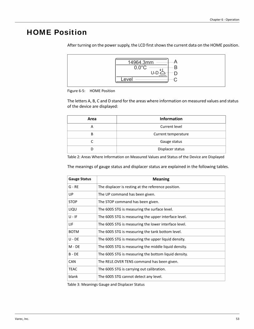
Chapter 6 - Operation
Varec, Inc. 53
HOME Position After turning on the power supply, the LCD first shows the current data on the HOME position.
Figure 6-5: HOME Position
The letters A, B, C and D stand for the areas where information on measured values and status of the device are displayed:
Table 2: Areas Where Information on Measured Values and Status of the Device are Displayed
The meanings of gauge status and displacer status are explained in the following tables.
Table 3: Meanings Gauge and Displacer Status
Area Information
A Current level
B Current temperature
C Gauge status
D Displacer status
Gauge Status Meaning
G - RE The displacer is resting at the reference position.
UP The UP command has been given.
STOP The STOP command has been given.
LIQU The 6005 STG is measuring the surface level.
U - IF The 6005 STG is measuring the upper interface level.
LIF The 6005 STG is measuring the lower interface level.
BOTM The 6005 STG is measuring the tank bottom level.
U - DE The 6005 STG is measuring the upper liquid density.
M - DE The 6005 STG is measuring the middle liquid density.
B - DE The 6005 STG is measuring the bottom liquid density.
CAN The RELE.OVER TENS command has been given.
TEAC The 6005 STG is carrying out calibration.
blank The 6005 STG cannot detect any level.
U-D0.0°C
ABDCLevel
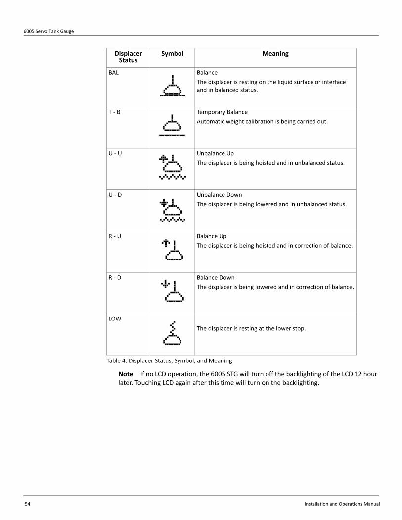
6005 Servo Tank Gauge
54 Installation and Operations Manual
Table 4: Displacer Status, Symbol, and Meaning
Note If no LCD operation, the 6005 STG will turn off the backlighting of the LCD 12 hour later. Touching LCD again after this time will turn on the backlighting.
Displacer Status
Symbol Meaning
BAL BalanceThe displacer is resting on the liquid surface or interface and in balanced status.
T - B Temporary BalanceAutomatic weight calibration is being carried out.
U - U Unbalance UpThe displacer is being hoisted and in unbalanced status.
U - D Unbalance DownThe displacer is being lowered and in unbalanced status.
R - U Balance UpThe displacer is being hoisted and in correction of balance.
R - D Balance DownThe displacer is being lowered and in correction of balance.
LOWThe displacer is resting at the lower stop.

Chapter 6 - Operation
Varec, Inc. 55
Access Code The access code is to ensure the confidentiality of the setup data. Three security levels are available, along with access codes.
Table 5: Security Levels with Access Codes
The higher levels include the lower ones. e.g. If access code 50 is specified for a function, then code 51 also enables editing. A function that requires access code 51, on the contrary, cannot be edited by code 50. However, 777 is only used to change the I.S. terminal configuration.
Figure 6-6: Order Code which Require Access Code 777
Security Level Access Code
0 None
1 For Operator 50
2 For Engineer 51/530/777
N6005- X X X X X X X X X X X
JNOU
NPFAH

6005 Servo Tank Gauge
56 Installation and Operations Manual
Setting an Access Code
Item Procedure Remarks
Static Matrix1. At the static matrix
“MORE FUNCTION”, select GVH=039 “ACCESS CODE”
2. The default value is “0”. Touch the “+” key.
3. The first digit increases to 9, then the second digit increases. Stop touching “+” once “50” is reached.
4. “50” is blinking. Gently touch “+” key again to change the first digit from 0 to 1. Now “51” is reached.
5. Here touch “E”; “EDITING ENABLE” will be displayed.
• When “E” is touched while displaying an access code except 0, 50, or 51 “EDITING LOCKED” will appear.
• If an access code has not been selected before performing any settings, the screen will automatically change to show “ACCESS CODE”
• Operation Commands can be sent, and displayed data read, by remote systems, depending on your 6005 STG specification.
MOREFUNCTION
ACCESS CODE
039

Chapter 6 - Operation
Varec, Inc. 57
Operation Command and New Operation Status
Operation Commands
Operation Commands can be sent the 6005 STG from a host system. Table 6 explains the command codes.
Table 6: Operation Commands
New Operation Status
The following table shows the new operation status, which is available when “NEW NMS STATUS”, matrix position GVH=272, is selected to “ENABLED”.
Code Command Remarks
0 LEVEL
1 UP
2 STOP After weight calibration, STOP is set as a default operation command
3 BOTTOM LEVEL
4 UPPER INTERF. LEVEL
5 MIDD.INTERF.LEVEL
6 UPPER DENSITY
7 MIDDLE DENSITY
8 DENSITY BOTTOM
9 REPEATABILITY
10 WATER DIP
Code Meaning 6005 STG Display
0 No definition -
1 Displacer at reference position REFERENCE
2 Displacer hoisting up UP
3 Displacer going down DOWN
4 Displacer stop STOP
5 Level measurement, balanced LEVEL
6 Upper I/F level, balanced UPPER INTERF. LEV.
7 Middle I/F level, balanced MIDD. INTERF. LEV.
8 Bottom meas. Balanced BOTTOM LEVEL
9 Upper density finished UPPER DENSITY
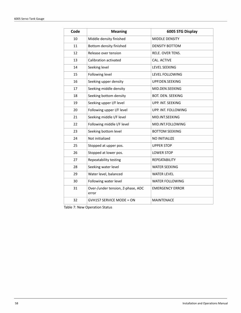
6005 Servo Tank Gauge
58 Installation and Operations Manual
Table 7: New Operation Status
10 Middle density finished MIDDLE DENSITY
11 Bottom density finished DENSITY BOTTOM
12 Release over tension RELE. OVER TENS.
13 Calibration activated CAL. ACTIVE
14 Seeking level LEVEL SEEKING
15 Following level LEVEL FOLLOWING
16 Seeking upper density UPP.DEN.SEEKING
17 Seeking middle density MID.DEN.SEEKING
18 Seeking bottom density BOT. DEN. SEEKING
19 Seeking upper I/F level UPP. INT. SEEKING
20 Following upper I/F level UPP. INT. FOLLOWING
21 Seeking middle I/F level MID.INT.SEEKING
22 Following middle I/F level MID.INT.FOLLOWING
23 Seeking bottom level BOTTOM SEEKING
24 Not initialized NO INITIALIZE
25 Stopped at upper pos. UPPER STOP
26 Stopped at lower pos. LOWER STOP
27 Repeatability testing REPEATABILITY
28 Seeking water level WATER SEEKING
29 Water level, balanced WATER LEVEL
30 Following water level WATER FOLLOWING
31 Over-/under tension, Z-phase, ADC error
EMERGENCY ERROR
32 GVH157 SERVICE MODE = ON MAINTENACE
Code Meaning 6005 STG Display

Chapter 6 - Operation
Varec, Inc. 59
Operation of the Displacer The operation of the displacer for level, bottom level, interface level, and density measurement is possible by touch control.
Table 8: Operation of the Displacer
Item Procedure Remarks
Static Matrix
Touch Control
1) Select function groupGVH=020 OPERATION
2) Select item OPERATION.The LCD shows the command given to the 6005 STG and the displacer position.
• Set access code to 50.
• If editing has previously been enabled by a valid access code, then the request for the code will not appear.
The following commands are available at this position:
LEVELUPSTOPBOTTOM LEVELUPPER INTERF. LEV*MIDD.INTERF.LEV*UPPER DENSITY*MIDDLE DENSITY*DENSITY BOTTOM*WATER DIP*REPEATABILITY TEST
* Interface and density measurements are not available unless specifically requested.* Density profile measurement is explained in Chapter .
• The optional operation commands are available when such options are set.
OPERATION OPERATION
Level
BottomLevel
Upper Interface Level
Middle Interface Level
Density Bottom
Water Dip
Middle Density
Upper Density
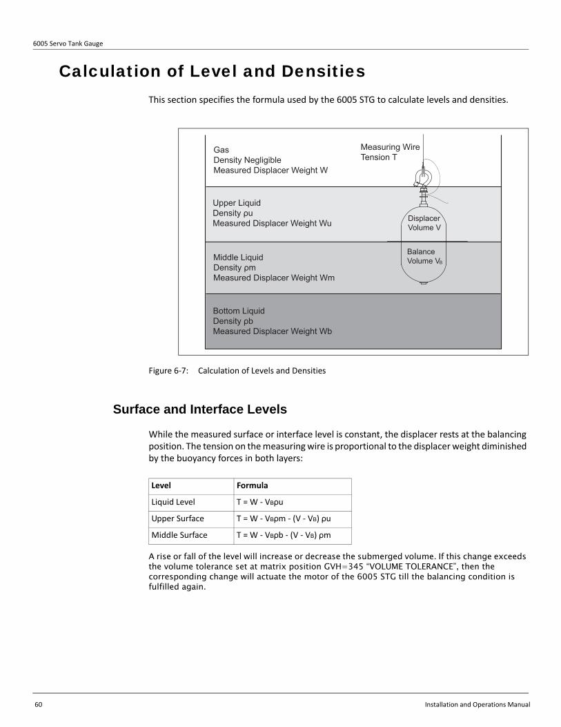
6005 Servo Tank Gauge
60 Installation and Operations Manual
Calculation of Level and Densities This section specifies the formula used by the 6005 STG to calculate levels and densities.
Figure 6-7: Calculation of Levels and Densities
Surface and Interface Levels
While the measured surface or interface level is constant, the displacer rests at the balancing position. The tension on the measuring wire is proportional to the displacer weight diminished by the buoyancy forces in both layers:
A rise or fall of the level will increase or decrease the submerged volume. If this change exceeds the volume tolerance set at matrix position GVH=345 “VOLUME TOLERANCE”, then the corresponding change will actuate the motor of the 6005 STG till the balancing condition is fulfilled again.
Measuring WireTension T
GasDensity NegligibleMeasured Displacer Weight W
Upper LiquidDensity ρuMeasured Displacer Weight Wu
Middle LiquidDensity ρmMeasured Displacer Weight Wm
Bottom LiquidDensity ρbMeasured Displacer Weight Wb
Balance Volume VB
DisplacerVolume V
Level Formula
Liquid Level T = W - VBρu
Upper Surface T = W - VBρm - (V - VB) ρu
Middle Surface T = W - VBρb - (V - VB) ρm

Chapter 6 - Operation
Varec, Inc. 61
Tank Bottom Level
For bottom level measurement, the balancing condition is defined as
Densities
The upper, middle, and bottom densities are calculated by the following formula.
• Upper density (pu) and Density profile
• Middle density (pm)
• Bottom density (pb)Draft
The draft depends on the shape of the displacer. For cylindrical shape, the draft is
where the variables and constants have the following meanings;
ρu =V
W - Wu
ρm =V
Wu - Wm ρu+
ρb =V
Wm - Wb ρm+
D = (V2 - V1) / A x 10 + h

6005 Servo Tank Gauge
62 Installation and Operations Manual
Figure 6-8: Draft
The surface or interface level should be within the cylindrical part of the displacer and approximately in the middle of its total height.
d
hV2
D
h1V3
Liquid level or Interface
= (V1 - V2 - V3) / A x 10 + h + h1
V1
V2
hA
Displacer Balance volume 69cm3)Displacer lower hemisphere volume
Height of the lower coneCross-section of the displacer
V1
V2
hA
Balance volume (69 cm3)Volume of the lower cone (24.46 cm3)
Displacer bottom stub height (20 mm)Cross-section of the displacer (20.26 cm2)
For example:standard displacer Ø50.8 mm Cylindrical shape
D = (69 - 24.46 - 0.12) / 20.26 x 10 + 20 + 3 = 44.92
V3 Displacer bottom stub volume
V3 Volume of the end of cone (0.12 cm3)
h Height of the end of cone1
1

Varec, Inc. 63
Chapter 7
Commissioning
Initial SettingsThis section explains initial settings required at commissioning. Some, or all, of these settings may be required, depending on the 6005 STG specification. Set Access code 51 at GVH039 before making these initial settings.
System calendar/clock (GVH193 to 197)
Calendar/Clock values are set at factory prior to delivery. Change the data to reflect local time.
Density values (GVH005 to 007)
Caution Always set GVH=005 Upper Density for actual density data, in LPG and any application where the actual density is less than 0.7000 g/ml. failure to set this data may result in level gauge malfunction.
Density values for 3 liquid phases are set to 1.000 g/ml prior to delivery. Change the data to reflect actual density values. For tanks with only one liquid phase, set Upper Density. For tanks with 2 or 3 clear phases, set Middle and Bottom densities too.
Note Minimum difference between phase settings should be at least 0.100 g/ml. *GVH005 ≤ GVH006 ≤ GVH007
Example:
• GVH005 Upper Density: 0.758• GVH006 Middle Density: 0.880• GVH007 Density Bottom: 1.000
Tank Height (GVH140)
Tank height value is set to default value at factory prior to delivery. Tank height is the reference height, usually a gauging hatch on the tank that is used during manual level measurements. Change GVH140 to equal the reference height. Note: GVH141 “Dip Point Offset” will automatically change to reflect the difference in height between the reference height and the 6005 STG reference position.
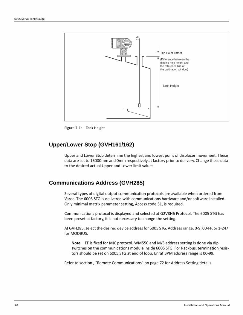
6005 Servo Tank Gauge
64 Installation and Operations Manual
Figure 7-1: Tank Height
Upper/Lower Stop (GVH161/162)
Upper and Lower Stop determine the highest and lowest point of displacer movement. These data are set to 16000mm and 0mm respectively at factory prior to delivery. Change these data to the desired actual Upper and Lower limit values.
Communications Address (GVH285)
Several types of digital output communication protocols are available when ordered from Varec. The 6005 STG is delivered with communications hardware and/or software installed. Only minimal matrix parameter setting, Access code 51, is required.
Communications protocol is displayed and selected at G2V8H6 Protocol. The 6005 STG has been preset at factory, it is not necessary to change the setting.
At GVH285, select the desired device address for 6005 STG. Address range: 0-9, 00-FF, or 1-247 for MODBUS.
Note FF is fixed for MIC protocol. WM550 and M/S address setting is done via dip switches on the communications module inside 6005 STG. For Rackbus, termination resis-tors should be set on 6005 STG at end of loop. Enraf BPM address range is 00-99.
Refer to section , "Remote Communications" on page 72 for Address Setting details.
Tank Height
Dip Point Offset
(Difference between the dipping hole height and the reference line of the calibration window)
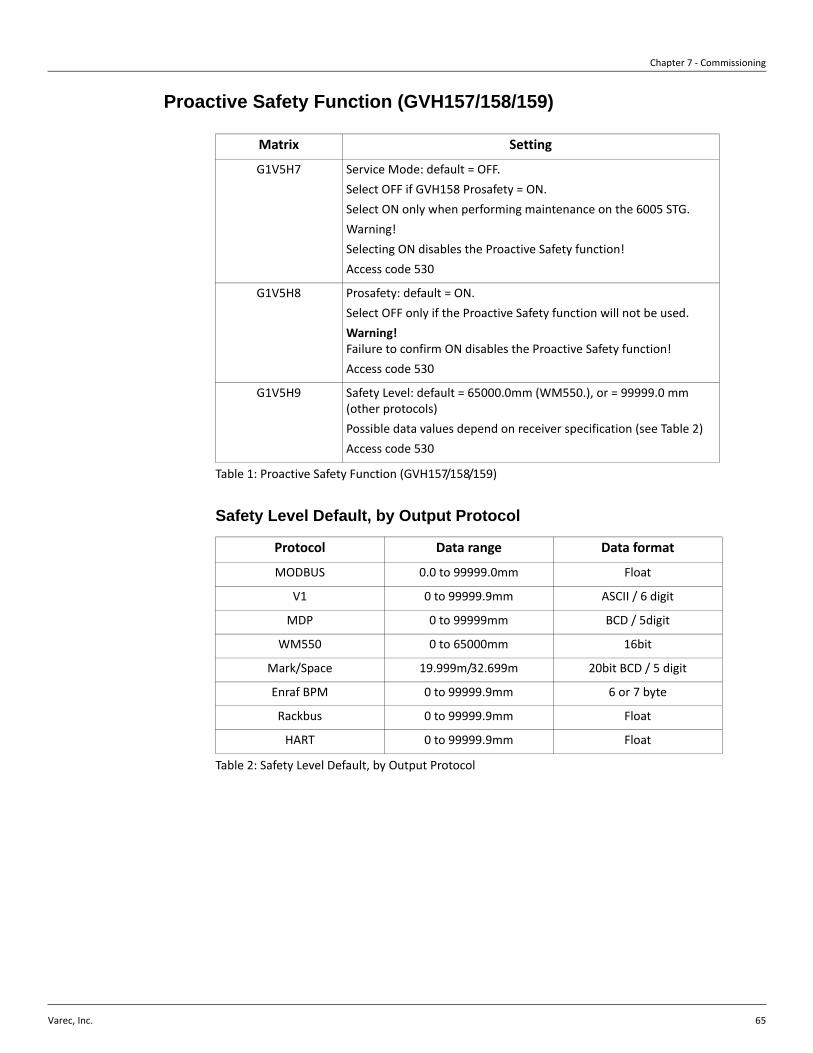
Chapter 7 - Commissioning
Varec, Inc. 65
Proactive Safety Function (GVH157/158/159)
Table 1: Proactive Safety Function (GVH157/158/159)
Safety Level Default, by Output Protocol
Table 2: Safety Level Default, by Output Protocol
Matrix Setting
G1V5H7 Service Mode: default = OFF. Select OFF if GVH158 Prosafety = ON.Select ON only when performing maintenance on the 6005 STG.Warning!Selecting ON disables the Proactive Safety function!Access code 530
G1V5H8 Prosafety: default = ON.Select OFF only if the Proactive Safety function will not be used. Warning!Failure to confirm ON disables the Proactive Safety function!Access code 530
G1V5H9 Safety Level: default = 65000.0mm (WM550.), or = 99999.0 mm (other protocols)Possible data values depend on receiver specification (see Table 2)Access code 530
Protocol Data range Data format
MODBUS 0.0 to 99999.0mm Float
V1 0 to 99999.9mm ASCII / 6 digit
MDP 0 to 99999mm BCD / 5digit
WM550 0 to 65000mm 16bit
Mark/Space 19.999m/32.699m 20bit BCD / 5 digit
Enraf BPM 0 to 99999.9mm 6 or 7 byte
Rackbus 0 to 99999.9mm Float
HART 0 to 99999.9mm Float

6005 Servo Tank Gauge
66 Installation and Operations Manual
Analog output (GVH250 to 256)
When specified and ordered from Varec, the 6005 STG is equipped with analog output hardware installed. Function settings may be changed as follows:
Table 3: Analog Output (GVH250 to 256) — Function Settings
Contact Relay Alarm output (GVH240 to 247)
When specified and ordered from Varec, the 6005 STG is equipped with contact relay alarm output hardware installed. Function settings may be changed as follows:
Table 4: Contact Relay Alarm Output (GVH240 to 247) — Function Settings
Function Setting
Assign Output 1 Assign level or temperature to channel 1 output.
Adjust 4mA Set desired value at which level or temperature outputs 4 mA.
Adjust 20mA Set desired value at which level or temperature outputs 20 mA
Assign Output 2 Assign level or temperature to channel 2 output.
Adjust 4mA Set desired value at which level or temperature outputs 4 mA
Adjust 20mA Set desired value at which level or temperature outputs 20 mA.
Device at Alarm Select type of output for alarm
Function Setting
Select Relay Select from Relay 1, 2, 3 or 4
Assign Relay Select output definition from range of choices: None, Level, Liquid Temperature, Caution, Warning, Emergency Error, Balance Signal
Relay Function Select High or Low
Switching Point: Set value at which relay is activated
Hysteresis Set hysteresis value for selected relay
Relay on Alarm Select from Normal Open or Normal Closed
On Delay Time Set time delay value for alarm output start
Off Delay Time Set delay value for alarm output stop

Chapter 7 - Commissioning
Varec, Inc. 67
Settings for the 453x Temperature Device Connections
The following settings are required to display 4539 Average Temperature Sensor/Water Bottom Sensor and Converter (ATC) data on 6005 STG screens.
Table 5: Settings for the 453x Temperature Device Connections
Caution For the 4535, 4539, and 4532 temperature device connections, refer to the appropriate operating manual for your device.
Item Procedure Remarks
Matrix Group: SERVICE
Static Matrix
1) In Static Matrix “MORE FUNCTION”, invoke
GVH=030 “MATRIX OF” and select “SERVICE”.
2) Invoke the Dynamic Matrix GVH=362
“CONNECTION 453x” screen.
3) Use the “+” and “-” keys to display “AVER-
AGE” and press “E” to set data.
4) Press “E” to return to “SYSTEM DATA” and press
the “-” key to return to “MORE FUNCTION”.
5) Invoke Static Matrix “GVH=030 MATRIX OF”. The 6005 STG matrix is
divided into matrix groups.
Select “TEMPERATURE” from these groups.
6) “EDITING ENABLED” is displayed on the LCD.
7) The average liquid temperature is displayed
on Dynamic Matrix screen GVH=440.
8) The temperature of each contact is displayed
on Dynamic Matrix screens GVH=450 to
GVH=459.
• Set access code 51.
• 6005 STG HART connection (terminal 24 & 25) must have corresponding IS input in order to configure 453x IS version.
• The Static Matrix GVH=010 “LIQUID TEMP.” screen also displays the average temperature.
MOREFUNCTION
SYSTEMDATA
CONNECTION NMT3 6 2
MATRIX OF0 3 0
MOREFUNCTION
MATRIX OF0 3 0

6005 Servo Tank Gauge
68 Installation and Operations Manual
Settings for the 4560 Servo Monitor Connections To connect a 4560 Servo Monitor, the 6005 STG requires the following settings.
Caution Turn on the power to 6005 STG first.
Table 6: Settings for the 4560 Servo Monitor Connections
Item Procedure Remarks
Matrix Group: SERVICE1. In Static Matrix
“MORE FUNC-TION”, invoke GVH=030 “MATRIX OF” and select “SERVICE”.
2. Invoke the Dynamic Matrix GVH=361 “CONNECTION NRF" screen.
3. Use the “+” and “-” keys to select either “CONTACT 1" or “CONTACT 2".
4. The setting is com-plete.
• Set access code 51.
• CONTACT 1...4560 Servo Monitorsoftware version 1.6x and earlier (those 4560 Servo Monitors that indicate no software version correspond to connection type 1).
• CONTACT 2...4560 Servo Monitor software version 1.8x and later.
MOREFUNCTION
SYSTEMDATA
CONNECTION NRF
3 6 1
MATRIX OF0 3 0

Chapter 7 - Commissioning
Varec, Inc. 69
Liquid Level Calibration
Open Tanks
Preparation
Select LEVEL at GVH020 Operation. The displacer will descend to the liquid surface and balance. When “BAL” is displayed, the displacer has stopped moving.
Manually measure the liquid level using an approved method.
Set Level (GVH150) for Open Tanks
At GVH150, input the liquid level obtained from manual measurement (above).
Figure 7-2: Calibration Level (manual dipping level)
ManualDipping Level
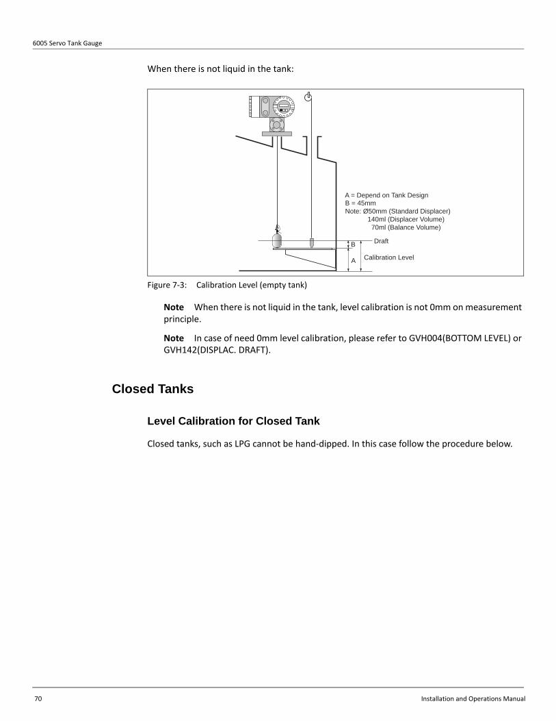
6005 Servo Tank Gauge
70 Installation and Operations Manual
When there is not liquid in the tank:
Figure 7-3: Calibration Level (empty tank)
Note When there is not liquid in the tank, level calibration is not 0mm on measurement principle.
Note In case of need 0mm level calibration, please refer to GVH004(BOTTOM LEVEL) or GVH142(DISPLAC. DRAFT).
Closed Tanks
Level Calibration for Closed Tank
Closed tanks, such as LPG cannot be hand-dipped. In this case follow the procedure below.
Draft
Calibration Level
B
A
B = 45mm Note: Ø50mm (Standard Displacer) 140ml (Displacer Volume) 70ml (Balance Volume)
A = Depend on Tank Design
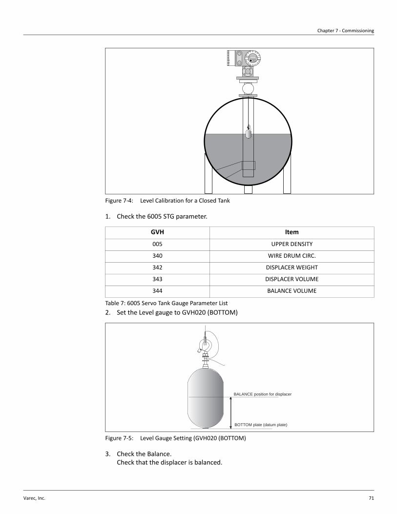
Chapter 7 - Commissioning
Varec, Inc. 71
Figure 7-4: Level Calibration for a Closed Tank
1. Check the 6005 STG parameter.
Table 7: 6005 Servo Tank Gauge Parameter List2. Set the Level gauge to GVH020 (BOTTOM)
Figure 7-5: Level Gauge Setting (GVH020 (BOTTOM)
3. Check the Balance.Check that the displacer is balanced.
GVH Item
005 UPPER DENSITY
340 WIRE DRUM CIRC.
342 DISPLACER WEIGHT
343 DISPLACER VOLUME
344 BALANCE VOLUME
BOTTOM plate (datum plate)
BALANCE position for displacer

6005 Servo Tank Gauge
72 Installation and Operations Manual
4. Calculate the displacer balance position. In case of Ø50 standard displacer, when balance volume(GVH343) is reference value (a half of displace volume), the balance point is 45mm from bottom.
Note Please refer to section , "Displacer" on page 6.
Figure 7-6: Level Calibration
5. Level CalibrationSet Level Calibration to 45mm at GVH150 (SET LEVEL) in G1 MATRIX (Calibration). The bot-tom is ZERO. If the bottom plate is not Zero (ex; X mm), please adjust the level value by adding to the value.
LEVEL = X + 45(mm)
Remote Communications
Digital Output
At G2V8H5 Address, set the desired loop address for most digital protocols. Depending on the protocol installed in the 6005 STG, the range of possible addresses differs. Range is 0-9, 00-FF (FF is fixed for MIC protocol), or 1-247 for MODBUS.
• WM550 and Mark Space protocols addresses must be set by switches on the communications module inside the 6005 STG.
• MODBUS: Termination resistors should be set on MODBUS modules (see section , "RS-485 MODBUS (COM- 5) Terminator" on page 1.
• Enraf BPM: Address range is 00-99. A-F are not available.
0mm
45mm
45mm

Chapter 7 - Commissioning
Varec, Inc. 73
Whessoe Matic 550 (WM550) Communication Board Setting
Jumper Setting
Jumper settings for WM550 communication board.
Table 8: Jumper Settings for the WM550 Communication Board• To loaded software into processor [IC1] J3 has to be open.• If software testing is required; J4 has to be open.• If software reset is required; J6 has to be short.
Polling Address Setting
Caution Polling addresses are set mechanically at SW1 on WM550 communication board (not by accessing the 6005 STG programming matrix). Check all polling addresses before setting.
Table 9 lists the address settings at SW1 on the WM550 communication board.
Table 9: SW1 Address Settings on the WM550 Communication Board
Note For current loop setting, please refer the Whessoe 1098 Operating Manual or the RTU 8130 Operating Manual.
Mark/Space (M/S) communication board setting
Jumper setting
Jumper settings for M/S communication board.
Jumper Function Default condition
J3 (Mode) Use EPROM [IC4]->short Short
J4 (Test) Software testing Short
J6 (Reset) Reset Open
J7 (Watch dog) Watch dog setting Short
Switch Posi-tion
Value
1 1
2 2
3 4
4 8
5 16
6 COMPATIBILITY MODE
ON
1 2 3 4 5 6
Polling address = 1
ON
1 2 3 4 5 6
Polling address = 5
ON
1 2 3 4 5 6
Polling address = 9
ON
1 2 3 4 5 6
Polling address = 3
ON
1 2 3 4 5 6
Polling address = 7
Setting Example
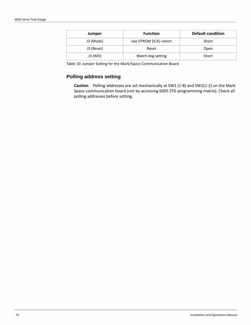
6005 Servo Tank Gauge
74 Installation and Operations Manual
Table 10: Jumper Setting for the Mark/Space Communication Board
Polling address setting
Caution Polling addresses are set mechanically at SW1 (1-8) and SW2(1-2) on the Mark Space communication board (not by accessing 6005 STG programming matrix). Check all polling addresses before setting.
Jumper Function Default condition
J3 (Mode) Use EPROM [IC4]->short Short
J3 (Reset) Reset Open
J3 (WD) Watch dog setting Short

Chapter 7 - Commissioning
Varec, Inc. 75
Table 9 lists the polling address settings on the Mark/Space communication board.
Table 11: Polling Address Settings on the Mark/Space Communication Board
Function Setting
Each function is set with SW-2 as shown in Table 12.
Table 12: SW2 — Function Setting
Switch Posi-tion
Value
SW1-1 1
SW1-2 2
SW1-3 4
SW1-4 8
SW1-5 16
SW1-6 32
SW1-7 64
SW1-8 128
SW2-1 256
SW2-2 512
Switch Function Default condition
SW2-3 ON: Data transmission under unbalanced condition ON
SW2-4 ON: low baud rate setting OFF
SW2-5 ON: Feet data OR 0-20m, OFF: 0-30m OFF
SW2-6 ON: Measured data converted to feet OFF
SW2-7 ON: Temperature data (57 bits) ON
SW2-8 ON: Deg. F measured temperature unit, OFF: Deg. C OFF
ON
1 2 3 4 5 6 7 8
ON
1 2 3 4 5 6 7 8
SW - 1 SW - 2
Address setting Function setting
Setting Example (above example:267)

6005 Servo Tank Gauge
76 Installation and Operations Manual
ENRAF Bi Phase communication board (COM-3) setting
Jumper setting
COM-3 Communication board jumper setting.
Table 13: ENRAF BI-Phase Communication (COM-3) Jumper Settings
Communication Setting
At the matrix position GVH=286, select “V1/ENRAF BPM”.
Communication Setting
Polling address setting is configured by accessing the 6005 STG matrix, GVH=285 “ADDRESS”. Valid polling addresses are 00–99.
Caution A-F are not valid polling addresses for ENRAF BPM communications.
Communication Setting
• Switch S1: Reset switch• Connector J3: Communication port for debugging
Jumper Function Default condition
JP1 (Mode)ROM type setting
1-2 short: 27C40962-3 short: 27C1024
2-3 short
JP2 (Reset)CPU mode setting (Fixed) 1-2 open
3-4 short5-6 short
J3 (WD)Baud rate setting
1-2 short: 1200 bps1-2 open: 2400 bps
1-2 open

Chapter 7 - Commissioning
Varec, Inc. 77
Analog Output
Analog output 4-20 mA is available when ordered from Varec. The 6005 STG is delivered with analog output hardware installed. For the following matrix parameter settings, Access code 51, is required.
Table 14: 6005 STG Matrix Parameter Settings via Access Code 51
Note If “LEVEL”, please confirm GVH158 (Prosafety) is “NO”.
Matrix Item Setting
G2V5H0 Assign Output Assign analog output (Level or Temperature) for channel 1.
G2V5H1 Adjust 4 mA Set level or temperature value for 4 mA output on channel 1.Available only when G2V5H0= “Level” or “Liquid Temp”Level: 0...99999mmTemperature: -999...999°CDefault: 0mm / 0°C
G2V5H2 Adjust 20 mA Set level or temperature value for 20mA output on channel 1. Available only when G2V5H0 = “Level” or “Liquid Temp.”Level: 0...99999mmTemperature: -999...999°CDefault: 0mm / 0°C
G2V5H3 Assign Output 2 Assign analog output (Level or Temperature) for channel 2.
G2V5H4 Adjust 4mA Set level or temperature value for 4mA output on channel 2. Available only when G2V5H3 = “Level” or “Liquid Temp.” Level: 0...99999mmTemperature: -999...999°CDefault: 0mm / 0°C
G2V5H5 Adjust 20mA: Set level or temperature value for 20mA output on channel 2. Available only when G2V5H3 = “Level” or “Liquid Temp.”Level: 0...99999mmTemperature: -999...999°CDefault: 0mm / 0°C
G2V5H6 Device at Alarm Select type of output for alarm. Select from OFF, HOLD current output, Maximum value or Minimum value. Default: OFF

6005 Servo Tank Gauge
78 Installation and Operations Manual
Contact Relay Alarm Output
Contact relay alarm output is available when ordered from Varec. The 6005 STG is delivered with analog output hardware installed. Maximum 4 contact relay alarm settings are available.
The following matrix parameter settings, Access code 51, are required.
Table 15: Matrix Parameter Settings via Access Code 51
Table 16 lists the possible error types and their meanings.
Table 16: Error Type and Meaning
Matrix Item Setting
G2V4H0 Select Relay Use +/- and E keys to select to activate Contact Output Relays 1 to 4. Default value = 1.
G2V4H1 Assign Relay Select output definition from range of choices: None, Level, Liquid Temp, Caution, Warning, Emergency Error, and Balance Signal. Default value = NONE.
G2V4H2 Relay Function Select High or Low function, available only when G2V4H1 = “Level” or “Liquid Temp.” Default value = HIGH.
G2V4H3 Switching Point Set level (0-99999 mm) at which relay is activated, available only when G2V4H1 = “Level” or “Liquid Temp.” Default value = 0 mm.
G2V4H4 Hysteresis Set hysteresis value (0-99999 mm) for selected relay, available only when G2V4H1 = “Level” or “Liquid Temp.” Default value = 0 mm.
G2V4H5 Relay on Alarm Select from Normal Open or Normal Closed, available only when G2V4H1 = “Level” or “Liquid Temp.” Default value = NORMAL OPENED.
G2V4H6 On Delay time Set delay time (0-999 seconds) for alarm output start, available only when G2V4H1 = “Level” or “Liquid Temp.” Default value = 0 seconds.
G2V4H7 Off Delay Time Set delay time (0-999 seconds) for alarm stop, available only when G2V4H1 = “Level” or “Liquid Temp.” Default value = 0 seconds.
Error type Meaning
LEVEL Upper or Lower limit exceeded
LIQUID TEMPERATURE Upper or Lower limit exceeded
CAUTION Auto wire calibration error; Auto displacer calibration error
WARNING Upper weight limit exceeded (GVH162); Lower weight limit exceeded (GVH163); Local communication error; 453x error; LCD error; communication error; EEROM data error
EMERGENCY ERROR Z-phase no input error; ADC sensor error; communication IC error; A-phase no input error, Driver error, power failure
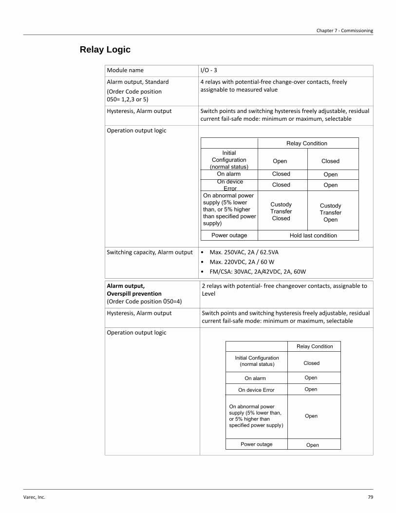
Chapter 7 - Commissioning
Varec, Inc. 79
Relay Logic
Module name I/O - 3
Alarm output, Standard(Order Code position 050= 1,2,3 or 5)
4 relays with potential-free change-over contacts, freely assignable to measured value
Hysteresis, Alarm output Switch points and switching hysteresis freely adjustable, residual current fail-safe mode: minimum or maximum, selectable
Operation output logic
Switching capacity, Alarm output • Max. 250VAC, 2A / 62.5VA• Max. 220VDC, 2A / 60 W• FM/CSA: 30VAC, 2A/42VDC, 2A, 60W
Alarm output, Overspill prevention (Order Code position 050=4)
2 relays with potential- free changeover contacts, assignable to Level
Hysteresis, Alarm output Switch points and switching hysteresis freely adjustable, residual current fail-safe mode: minimum or maximum, selectable
Operation output logic
Relay Condition
Initial Configuration
(normal status)Open Closed
On alarm Closed OpenOn device
ErrorClosed Open
On abnormal power supply (5% lower than, or 5% higher than specified power supply)
Custody Transfer Closed
Custody Transfer
Open
Power outage Hold last condition
Relay Condition
Initial Configuration(normal status) Closed
On alarm Open
On device Error Open
On abnormal power supply (5% lower than, or 5% higher than specified power supply)
Open
Power outage Open
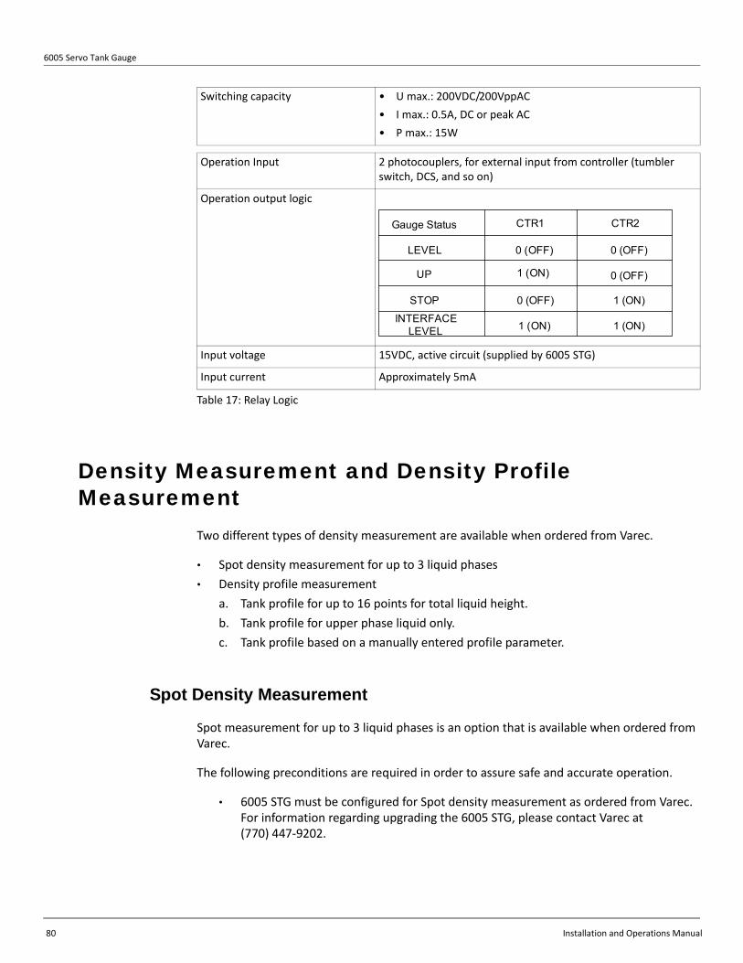
6005 Servo Tank Gauge
80 Installation and Operations Manual
Table 17: Relay Logic
Density Measurement and Density Profile Measurement
Two different types of density measurement are available when ordered from Varec.
• Spot density measurement for up to 3 liquid phases• Density profile measurement
a. Tank profile for up to 16 points for total liquid height.b. Tank profile for upper phase liquid only.c. Tank profile based on a manually entered profile parameter.
Spot Density Measurement
Spot measurement for up to 3 liquid phases is an option that is available when ordered from Varec.
The following preconditions are required in order to assure safe and accurate operation.
• 6005 STG must be configured for Spot density measurement as ordered from Varec. For information regarding upgrading the 6005 STG, please contact Varec at (770) 447-9202.
Switching capacity • U max.: 200VDC/200VppAC• I max.: 0.5A, DC or peak AC • P max.: 15W
Operation Input 2 photocouplers, for external input from controller (tumbler switch, DCS, and so on)
Operation output logic
Input voltage 15VDC, active circuit (supplied by 6005 STG)
Input current Approximately 5mA
Gauge Status CTR1 CTR2
LEVEL
UP
STOP
INTERFACE LEVEL
0 (OFF)
1 (ON)
0 (OFF)
1 (ON)
0 (OFF)
0 (OFF)
1 (ON)
1 (ON)

Chapter 7 - Commissioning
Varec, Inc. 81
• Density values:
Figure 7-7: Density Values
Density values can be viewed and changed at the following matrix positions:
• G0V0H5 Upper Density• G0V0H6 Middle Density• G0V0H7 Density Bottom
• The displacer is balanced at liquid level and the liquid surface is not moving.
For spot density measurement, set or select the following parameters. Alternatively, accepting the factory default settings is also an option:
Table 18: Spot Density Measurement
Operation
At G0V2H0 “OPERATION”, select the desired density operation: UPPER DENSITY, MIDDLE DENSITY, or DENSITY BOTTOM. The 6005 STG raises the displacer up out of the liquid, measures its weight, and sends the displacer down to measure density. After density is measured the displacer remains at that position until UP or LEVEL command are selected at G0V2H0 “Operation.”
Figure 7-8: Density Profile Measurement
Matrix Item Setting
G1V4H3 Displacer Raise Dens
Set distance (0-300mm) for displacer to rise above level position during Density operations. Default setting = 150 mm. Observe the rule: G1V4H3 + G1V4H4 = 300 n, where n = integer.
G1V4H4 Displacer Subm. Dens
Set distance (0-300mm) for displacer to sink below level position during Density operations. Default setting = 150 mm. Observe the rule: G1V4H3 + G1V4H4 = 300 n, where n = integer.
e.g. 0.760 g/cm3
e.g. 0.880 g/cm3
e.g. 0.1000 g/cm3
(Example)
- Upper Density < Middle Density < Bottom Density Middle Density - Upper Density 0.100 g/ cm3
Bottom Density - Middle Density 0.100 g/ cm3
Upper Layer (Gas or Liquid)
Lower Layer(Liquid)
A
B

6005 Servo Tank Gauge
82 Installation and Operations Manual
Density Profile Measurement
Tank profile density measurement
In addition to the preconditions, the following additional preconditions are required in order to assure safe and accurate operation for tank profile density measurement. Access Code 51 is required to edit parameters.
• 6005 STG must be configured for Spot & Profile density measurement as ordered from Varec. For information regarding upgrading the 6005 STG, please contact Varec at (770) 447-9202.
• Tank Bottom Level GVH004 must = 0 If not, (e.g. actual bottom = 884mm) 6005 STG will try to calculate profile intervals based on Measured Level divided by OPE. Point (GVH000 / GVH841). But the displacer will hit bottom before being able to measure points below e.g. 884mm.
• If Bottom Level is not 0 mm, select Manual I/F Profile at GVH840. Set GVH843 I/F Manual Level = actual bottom level e.g. 884mm. In this case the intervals will be calculated based on (GVH000 - GVH843)/GVH841.
• There must be no movement or transfer of product, into or out of the tank, during density profile operation. Note that, depending on the height of liquid in the tank, density profile operation may take 1 hour or more.
Table 19: Tank Profile Density Measurement
Note Additional matrix parameter settings are required for remote communications via WM550 communications protocol.
Refer to section , "Programming Matrix" on page 119, (Dynamic Matrix, Device Data: G2), WM550 DENS. SEL.).
A. Tank profile for up to 16 points for total liquid heightG8V4H0 Ope Select: Select 1: Tank Profile.
B. Tank profile for upper phase liquid only G8V4H0 Ope Select: Select 2: I/F Profile.
C. Tank profile for based on a manually entered profile parameter.G8V4H0 Ope Select: Select 3: MANU.I/F Profile.
For choices A, B, and C above, set or select the following parameters. Alternatively, accepting the factory default settings is also an option:
Matrix Item Setting
G1V5H4 Safe Density Select the desired resultant condition when density profile measurement fails due to displacer reaching the low-limit for density profile operation (set in G1V5H5). Selecting “ON” will result in STOP operation. Selecting “IGNOR” will result in “LEVEL” operation, displacer will return to liquid level. Selecting “OFF” will leave the displacer at the position where density profile measurement failed, and in “DENSITY” operation.
G1V5H5 Den Ope Level Set the lower limit for displacer movement during density profile operation. Default setting = 300 mm.

Chapter 7 - Commissioning
Varec, Inc. 83
Table 20: Factory Default Settings
Matrix Item Setting
G8V4H1 Ope Point Set the number of measurement points (2-16) for Tank Profile measurement. Default setting = 2.
G8V4H3 I/F Manu. Level Manually set the water interface level (0-99999.9mm) to be referenced during Tank Profile measurement. Default setting = 0 mm. Only used with C, tank profile for based on a manually entered profile parameter.
G8V4H4 Bal. Level Set the allowance for level movement (1.0 -99.9 mm) prior to Tank Profile operation. If level movement exceeds this value, Profile operation is canceled. Setting 99.9mm allows Profile measurement to proceed, regardless of level movement. Default setting = 2.0 mm.
G8V4H5 Up Wait Time Set waiting time (1-31 minutes) for displacer weight to be measured in air, when making the weight table at start of Profile operation. Default setting = 1 minute.
G8V4H6 Liq Wait Time Set the time (1-31 minutes) for displacer to stop at each measurement position during profile operation. Default setting = 1 minute.
G8V4H7 Ope Wait Time Set maximum waiting time (1-31 minutes) for conditions in G8V4H4 (Bal Level) to be satisfied before profile operation begins. E.g. if level movement exceeds setting at G8V4H4, 6005 STG is in “standby” for the time set in this matrix. After the maximum time elapses, profile operation is canceled. Default setting = 1 minute.

6005 Servo Tank Gauge
84 Installation and Operations Manual
Initial Setting of Tank Profile (density profile) Measurement
All of the necessary set up can be done at the “G8 Tank Profile” matrix as explained earlier. There are six factors to be configured prior to the actual operation.
Table 21: G8V4H0 OPE. SELECT
Table 22: G8V4H1 OPE. POINT
Item Procedure Remarks
• Select G0V3H0 “MATRIX OF” in the row “MORE FUNCTION” on Static Matrix, then select “Tank profile”.
Set access code to 50
• Select function group “PROFILE OPE” and G8V4H0 “OPE SELECT”.
The row of PROFILE OPE is the only function group that needs configuration for the density profile operation.
• Select 1: “TANK PROFILE” by pressing + or - key.
• Then press E to configure.
Selection of “0:SPOT” enables Upper Density measurement instead of Density Profile measurement.
Item Procedure Remarks
• Select G8V4H1 “OPE POINT” to determine number of density measuring points.
• Set access code to 51. Default value is 2 points and selectable up to 16 points.
• Enter required number by pressing + or - key, and E to confirm.
• Whatever the number of measuring point is selected, the measuring interval & point between each point are automatically calculated within the liquid level.
Static Matrix
MOREFUNCTION Matrix of
TANK PROFILE
PROFILEOPE.
OPE.SELECT
STATUSDATADENSITY1-10DENSITY11-16
Position1-10Position10-16
Dynamic Matrix
Function Group
GVH=840
GVH=030
Matrix Group : TANK PROFILE
PROFILEOPE.
OPE.POINT
Function Group
Matrix Group: TANK PROFILE

Chapter 7 - Commissioning
Varec, Inc. 85
Table 23: G8V4H4 BAL. LEVEL
Table 24: G8V4H5 UP WAIT TIME
Item Procedure Remarks
• Select G8V4H4 “BAL LEVEL” to determine the liquid stability range in order to start the operation.
• Set access code to 51. 6005 STG software has a function to scan & record the liquid level every 5 minutes.
• Enter desired value by pressing + or - key and E to confirm. Input value of 99.9mm represents that activation of measuring procedure regardless of level condition.
• 6005 STG only starts the actual measurement when the liquid level is within the entered value compared to the recorded level data 5 minutes ago. This function ensures the safe operating condition to avoid filling or draining liquid from the tank.
Item Procedure Remarks
• Select G8V4H4 “UP WAIT TIME” to determine the displacer weight calibration interval in air.
• Set access code to 51. The displacer raises approximately 500mm above liquid surface after confirming the stability of liquid level within “BAL LEVEL” function.
• Enter desired waiting time by pressing + or - key, and E to confirm.
• The displacer weight is calibrated at 8 different positions in air and the interval between those positions is adjustable within this function to allow excess liquid to drip off the displacer to achieve higher accuracy.
TANKPROFILE
Function Group
BAL.LEVEL
GVH=844
Matrix Group : TANK PROFILE
TANKPROFILE
Function Group
UP.WAITTIME
GVH=845
Matrix Group : TANK PROFILE

6005 Servo Tank Gauge
86 Installation and Operations Manual
Table 25: G8V4H6 LIQ. WAIT TIME
Table 26: G8V4H7 OPE. WAIT TIME
Operation of Tank Profile (Density Profile) Measurement
After all of initial settings are completed, the actual operation can be proceeded by one simple command. The operation status regarding this function is displayed on G8V5H0 and the liquid level condition is also displayed on G8V5H1. Terms of status display and descriptions are listed below.
Item Procedure Remarks
• Select G8V4H6 “LIQ. WAIT TIME” to determine the displacer weight calibration interval between each measuring point in the liquid.
• Set access code to 51. A small turbulence made by the movement of displacer itself may cause the liquid surrounding displacer to be unstable for the precise measurement.
• Enter desired waiting time by pressing + or - key, and E to confirm.
• This function allows displacer to hold in each calculated position before actual measurement is proceeded based on the entered value.
Item Procedure Remarks
• Select G8V4H7 “OPE. WAIT TIME” to determine the operation holding time limit to accept “BAL. LEVEL” before the actual operation starts.
• Set access code to 51. Entire operation begins only when the condition described in “BAL. LEVEL” is achieved.
• Enter desired waiting time by pressing + or - key, and E to confirm.
• This function determines how long for the 6005 STG to wait if “BAL. LEVEL” can not be established before quitting entire operation.
Status Content
0: Accepting Accepting density profile command
1: Standby Ready to execute density profile command
TANKPROFILE
Function Group
LIQ. WAITTIME
GVH=846
Matrix Group : TANK PROFILE
TANKPROFILE
Function Group
OPE. WAITTIME
GVH=847
Matrix Group : TANK PROFILE

Chapter 7 - Commissioning
Varec, Inc. 87
Table 27: Operations Status (G8V5H0, OPE. STATUS)
Table 28: Level Condition Status (G8V5H1, LEVEL CONDITION)
Table 29: Static Matrix
2: In operation Executing density profile command
3: OPR. END Density profile operation completed successfully
4: UN_BALANCE ERR Fail: Required conditions for density profile operation not satisfied
5: IPR. ERR. STOP Fail: Abnormal conditions occurred during density profile operation
Status Content
0: Off Level Meas. Active operation is not LEVEL (Profile cannot start)
1: Stable Liquid level/surface is stable (Profile can start)
2: Unstable Liquid level/surface is unstable (Profile cannot start)
3: Ignore condition Ignores liquid level/surface condition (profile cannot start)
Item Procedure Remarks
• Select G0V2H0 “OPERATION” in the Static Matrix, then select “UPPER DENSITY”.
• Set access code to 50. • The operation command
“UPPER DENSITY” is shared between spot and Tank Profile density measurement depends on G8V4H0 configuration.
• Press E to start the operation.
• The operation must start when the 6005 STG is in Level measuring mode.
• Unless there are any incompatible circumstances during the operation, the displacer automatically returns to the level measurement after the last measuring point.
• To minimize the risk of safe operation, the displacer immediately returns to the Level measurement regardless of completing various data processes.
Status Content
Static Matrix
GVH=020
OPERATION OPERATION
LEVELUPSTOPBOTTOM LEVELMIDDLE INTER LEVELUPPER DENSITYMIDDLE DENSITYDENSITY BOTTOMREPEATABLITYWATER DIP
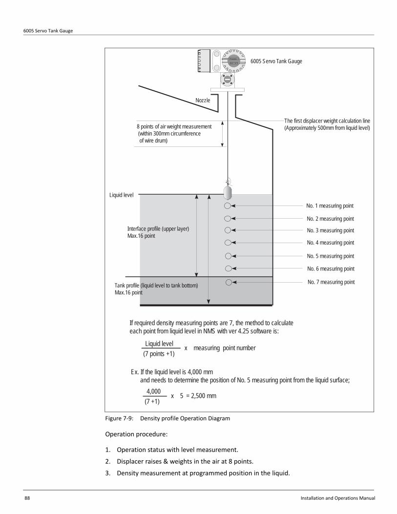
6005 Servo Tank Gauge
88 Installation and Operations Manual
Figure 7-9: Density profile Operation Diagram
Operation procedure:
1. Operation status with level measurement.
2. Displacer raises & weights in the air at 8 points.
3. Density measurement at programmed position in the liquid.
8 points of air weight measurement (within 300mm circumference of wire drum)
Nozzle
6005 Servo Tank GaugeProservo
The first displacer weight calculation line(Approximately 500mm from liquid level)
No. 1 measuring point
No. 2 measuring point
No. 3 measuring point
No. 4 measuring point
No. 5 measuring point
No. 6 measuring point
No. 7 measuring point
If required density measuring points are 7, the method to calculate each point from liquid level in NMS with ver 4.25 software is:
(7 points +1)Liquid level x measuring point number
Ex. If the liquid level is 4,000 mm and needs to determine the position of No. 5 measuring point from the liquid surface;
(7 +1)4,000 x 5 = 2,500 mm
Interface profile (upper layer)Max.16 point
Tank profile (liquid level to tank bottom)Max.16 point
Liquid level
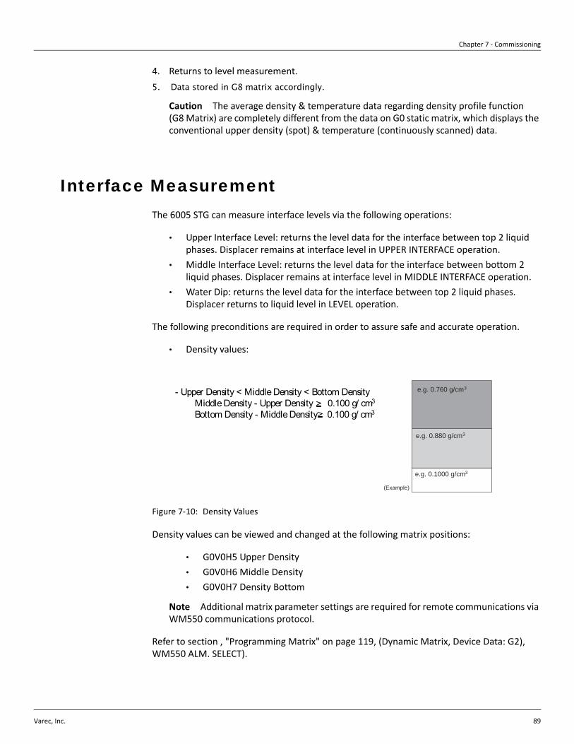
Chapter 7 - Commissioning
Varec, Inc. 89
4. Returns to level measurement.5. Data stored in G8 matrix accordingly.
Caution The average density & temperature data regarding density profile function (G8 Matrix) are completely different from the data on G0 static matrix, which displays the conventional upper density (spot) & temperature (continuously scanned) data.
Interface Measurement The 6005 STG can measure interface levels via the following operations:
• Upper Interface Level: returns the level data for the interface between top 2 liquid phases. Displacer remains at interface level in UPPER INTERFACE operation.
• Middle Interface Level: returns the level data for the interface between bottom 2 liquid phases. Displacer remains at interface level in MIDDLE INTERFACE operation.
• Water Dip: returns the level data for the interface between top 2 liquid phases. Displacer returns to liquid level in LEVEL operation.
The following preconditions are required in order to assure safe and accurate operation.
• Density values:
Figure 7-10: Density Values
Density values can be viewed and changed at the following matrix positions:
• G0V0H5 Upper Density• G0V0H6 Middle Density• G0V0H7 Density Bottom
Note Additional matrix parameter settings are required for remote communications via WM550 communications protocol.
Refer to section , "Programming Matrix" on page 119, (Dynamic Matrix, Device Data: G2), WM550 ALM. SELECT).
e.g. 0.760 g/cm3
e.g. 0.880 g/cm3
e.g. 0.1000 g/cm3
(Example)
- Upper Density < Middle Density < Bottom Density Middle Density - Upper Density 0.100 g/ cm3
Bottom Density - Middle Density 0.100 g/ cm3

6005 Servo Tank Gauge
90 Installation and Operations Manual
Operation:
After confirming the above preconditions, use the “+” or “-” keys to select the desired operation at matrix position G0V2H0 OPERATION. When the desired operation is displayed, press the “E” key.
Sealing of the 6005 STG The 6005 STG can be sealed, and data can be made unchangeable for custody transfer purposes as follows.
Set OPE. DENSITY at position GVH=278 as the density of the liquid. (If the density is expected to change during operation, then set the average value.)
Turn off the power supply, open the 6005 STG.
Turn the micro switch to “on position” on the printed circuit board TCB (see Figure 7-11). The 6005 STG will then set “write-protect” mode and not accept any change of level, weight, and density data.
Figure 7-11: The Printed Circuit Board TCB
220
91
61
131
1
CN
BC
N5
CN
7C
N6
CN
14
SW1
U1
4 1
5
4 1
5 8
58 1
4 58 1
4
U20 U19
U15 U13
U10
141
1528
1
16
8
9
17
8
U14
U9
U21
U7
U4
U11
U12
1
14
7
8
1
16
U24
U6
9
8
C16
C8
C7
U2
DC-DC Converter
C35
U3
C38 ON OFFCN9
CN2CN3
TCBCD_L423
Protect Switch
Varec, Inc. 91
Chapter 8
Maintenance The 6005 STG measuring instrument requires no special maintenance.
Exterior Cleaning When cleaning the exterior of measuring devices, always use cleaning agents that do not attack the surface of the housing and the seals.
Replacing Seals O-rings on the 6005 STG may need to be replaced periodically, especially in extreme environments. The period between changes depends on the severity of the environment, and on the temperature of the ambient and process.
Repairs The Varec repair concept assumes that the measuring devices have a modular design and that customers are able to undertake repairs themselves (see section , "Spare Parts" on page 104). Please contact Varec at (770) 447-9202 for further information on service and spare parts.
Repairs to Ex-approved Devices When carrying out repairs to Ex-approved devices, please note the following:
• Repairs to Ex-approved devices may only be carried out by trained personnel or by the Varec Service.
• Comply with the prevailing standards, national Ex-area regulations, safety instructions and certificates.
• Only use original spare parts from Varec.• When ordering a spare part, please note the device designation on the nameplate.
Only replace parts with identical parts.• Carry out repairs according to the instructions. On completion of repairs, carry out
the specified routine test on the device.• Only Varec Service can convert a certified device into a different certified variant.• Document all repair work and conversions.
6005 Servo Tank Gauge
92 Installation and Operations Manual
Replacement After a complete 6005 STG or electronic module has been replaced, a new sensor adjustment is required.
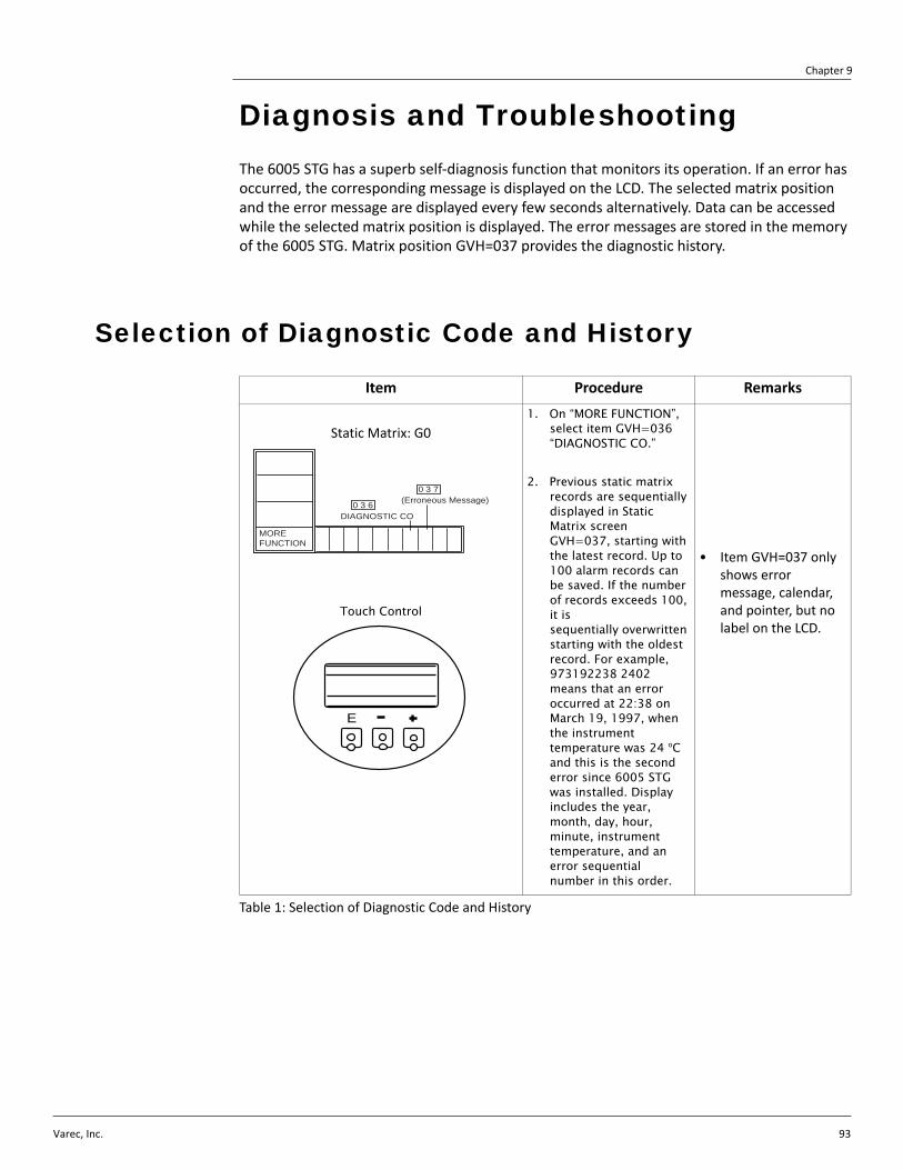
Varec, Inc. 93
Chapter 9
Diagnosis and Troubleshooting The 6005 STG has a superb self-diagnosis function that monitors its operation. If an error has occurred, the corresponding message is displayed on the LCD. The selected matrix position and the error message are displayed every few seconds alternatively. Data can be accessed while the selected matrix position is displayed. The error messages are stored in the memory of the 6005 STG. Matrix position GVH=037 provides the diagnostic history.
Selection of Diagnostic Code and History
Table 1: Selection of Diagnostic Code and History
Item Procedure Remarks
Static Matrix: G0
Touch Control
1. On “MORE FUNCTION”, select item GVH=036 “DIAGNOSTIC CO.”
2. Previous static matrix records are sequentially displayed in Static Matrix screen GVH=037, starting with the latest record. Up to 100 alarm records can be saved. If the number of records exceeds 100, it is sequentially overwritten starting with the oldest record. For example, 973192238 2402 means that an error occurred at 22:38 on March 19, 1997, when the instrument temperature was 24 oC and this is the second error since 6005 STG was installed. Display includes the year, month, day, hour, minute, instrument temperature, and an error sequential number in this order.
• Item GVH=037 only shows error message, calendar, and pointer, but no label on the LCD.
MOREFUNCTION
DIAGNOSTIC CO
(Erroneous Message)0 3 6
0 3 7

6005 Servo Tank Gauge
94 Installation and Operations Manual
Error and Status Messages
Message Cause Remedy Error code
-49.5 ºC Indication of shorted element in 453x temperature sensor.
Check GVH=450 thru GVH=459 to see element.
358.0 ºC Element is not enabled, or not installed in 453x Temperature Sensor.
Check GVH=482 Total number of elements
359.0 ºC Indication of open element in 453x temperature sensor.
Check GVH=450 thru GVH=459 to see element.
ADC/SENSOR ERROR The signal from the A/D converter is out of range.
Consult Varec Service. 107
ADJ. XXXCOUNTER(X=A, I, Z or combination)
Error of level data check by A, I, and/or Z phase encoder.
If the message appears frequently, then consult Varec Service.
A PHASE NO INPUT The input of the A phase signal from the encoder is not available.
Replace the detector unit. Consult Varec Service. 122
BELOWBOT. POINT Indicates 6005 STG displacer position is below the lowest N453x temperature sensor element.
DEVICE ERROR: DEV 1 (or 2)
The HART device 1 (or 2) gives an error signal.
Check the HART device 1 (or 2) . 130, 131
DEVICE ERROR: NMT
The N453x Temperature Devices give an error signal.
Check the connection of the N453x Temperature Device. Check the register of the temperature sensor at position GVH=362 “CONNECTION NMT.”
250
DEVICE ERROR: NMT
The N453x temperature sensor is not available.
Check the N453x Temperature Devices. Error messages are available in the N453x manual.
233
DEVICE ERROR: NRF
The 4560 Servo Gauge Monitor gives an error signal.
Check the 4560 SGM. Error messages are available in the N4560 Servo Gauge Monitor manual.
240
DISPL CALIB ERROR The deviation of automatic weight calibration exceeds its set limit.
Check build-up or deposit on the displacer. 120
ELEM 0 RANGE OVER Indicates the reference resistance element (ºC) on the temperature sensor electronics is out- of- tolerance.
IMPOSSIBILITY Operation is impossible because there is no weight table.
LOCAL ERROR: DEV1 (or 2)
The 6005 STG cannot access the local HART device 1 (or 2)
Check the connection of the HART device to the 6005 STG. Check the registration of the device(s) in matrix group G5/6.
232
LOCAL ERROR: NMT
The signal from the N453x temperature sensor is not available.
Check the connection of the N453x Temperature Device. Check the register of the Temperature Sensor at position GVH=362 “CONNECTION NMT.”
111
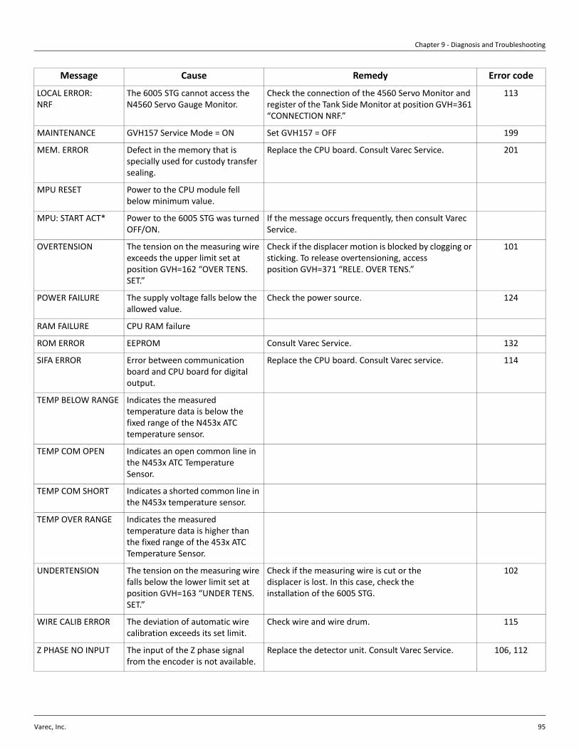
Chapter 9 - Diagnosis and Troubleshooting
Varec, Inc. 95
LOCAL ERROR: NRF
The 6005 STG cannot access the N4560 Servo Gauge Monitor.
Check the connection of the 4560 Servo Monitor and register of the Tank Side Monitor at position GVH=361 “CONNECTION NRF.”
113
MAINTENANCE GVH157 Service Mode = ON Set GVH157 = OFF 199
MEM. ERROR Defect in the memory that is specially used for custody transfer sealing.
Replace the CPU board. Consult Varec Service. 201
MPU RESET Power to the CPU module fell below minimum value.
MPU: START ACT* Power to the 6005 STG was turned OFF/ON.
If the message occurs frequently, then consult Varec Service.
OVERTENSION The tension on the measuring wire exceeds the upper limit set at position GVH=162 “OVER TENS. SET.”
Check if the displacer motion is blocked by clogging or sticking. To release overtensioning, access position GVH=371 “RELE. OVER TENS.”
101
POWER FAILURE The supply voltage falls below the allowed value.
Check the power source. 124
RAM FAILURE CPU RAM failure
ROM ERROR EEPROM Consult Varec Service. 132
SIFA ERROR Error between communication board and CPU board for digital output.
Replace the CPU board. Consult Varec service. 114
TEMP BELOW RANGE Indicates the measured temperature data is below the fixed range of the N453x ATC temperature sensor.
TEMP COM OPEN Indicates an open common line in the N453x ATC Temperature Sensor.
TEMP COM SHORT Indicates a shorted common line in the N453x temperature sensor.
TEMP OVER RANGE Indicates the measured temperature data is higher than the fixed range of the 453x ATC Temperature Sensor.
UNDERTENSION The tension on the measuring wire falls below the lower limit set at position GVH=163 “UNDER TENS. SET.”
Check if the measuring wire is cut or the displacer is lost. In this case, check the installation of the 6005 STG.
102
WIRE CALIB ERROR The deviation of automatic wire calibration exceeds its set limit.
Check wire and wire drum. 115
Z PHASE NO INPUT The input of the Z phase signal from the encoder is not available.
Replace the detector unit. Consult Varec Service. 106, 112
Message Cause Remedy Error code

6005 Servo Tank Gauge
96 Installation and Operations Manual
*These error histories are available (Erroneous Message) at position GVH=037.
MPU:XXXX*(XXXX=text)
CPU error The error might happen occasionally and might be registered in GVH=037 (Erroneous Message). However, it is normally negligible. If it occurs frequently, then consult Varec Service.
OPE.CODE ERROR An illegal operation command is accessed.
If the message occurs frequently, then consult Varec Service.
LCD CHECK Error between LCD (touch control) unit and CPU board for digital output.
Replace the touch control. 121
GAUGE TEMP. The temperature inside the gauge exceeds the limit.
Check if the ambient temperature stays within the limit. If the application is a high temperature tank, then take measures to avoid heat transfer from the tank to the 6005 STG.
DRIVER ERROR A motor driver error has occurred Consult Varec Service
Message Cause Remedy Error code

Chapter 9 - Diagnosis and Troubleshooting
Varec, Inc. 97
Diagnostics and Troubleshooting: Flowcharts
Figure 9-1: Diagnostics and Troubleshooting: Flowcharts
For up to 10 elements,check G4V5H0 thru H9 tofind shorted element.For more than 10elements, select element at G4V7H0, viewtemperature at G4V7H3.
(Level display)
-49.5 C
Wire ring at normal position ?
May require complete 453x exchange. Send allTemperature matrix (G4)data to Varec
359.0 C
TEMP. NO. n
ADJ(A, I, Z) COUNTER
YYMMDDhhmm TT ##
Raise displacer to red linein calibration window, orinto maintenancechamber.
G3V5H0 = G3V5H1 = 0?
3V5H0 = G3V5H1 = 0?
Displacer stopped atUpper Stop, G1V6H0?
Meaning:Shorted element in 453x ATCtemperature
Meaning:Element not enabled, or notinstalled in 453x ATC
This is an indicator, not anerror code. Verify totalnumber of elements atG4V8H2.
Diagnostic : -49.5 C
Diagnostic : 358.0 C (at G4V5_or G4V7H3)
Diagnostic : 359.5 C
(Level display)
359.5 C
Meaning:Open element in 453x ATC
For or up to 10 elements,check G4V5H0 thru H9 tofind open element.For more than 10 elements,
select element at G4V7H0, view temperature at
G4V7H3.
May require complete453x exchange. Send allTemperature matrix (G4)data to Varec.
Diagnostic : ADC SENSOR ERROR
ADC SENSOR ERROR
YYMMDDhhmm TT ##
Meaning:The A/D signal output fromthe detector unit, or input toCPU, is abnormal.
Exchange detector unit,adjust Hall sensors,recalibrate.
Make connections firm.TCB CN5, CN7 loose?
Diagnostic : ADJ A, I, or Z COUNTER
Automatic softwareadjustment workingnormally. Sometimes seenin turbulent applications.
Noise interface to internalsoftware counters.Eliminate noise, adjust Hall sensors, recalibrate.
Raise displacer manually(G3V7H6) until red line inwindow.
Diagnostic : A PHASE NO INPUT
A PHASE NO INPUT
YYMMDDhhmm TT ##
Meaning:The A-phase signal outputfrom the encoder, or inputto CPU is abnormal.20 outputs = 360 degrees.
Exchange detector unit,adjust Hall sensors,recalibrate.
Make connections firm.TCB CN5, CN7 loose?
OK?
Meaning:Automatic softwareadjustment workingnormally. Sometimes seen inturbulent applications.
Yes
No
Yes
No
Yes
No
Yes
No
No
Yes
No
Yes
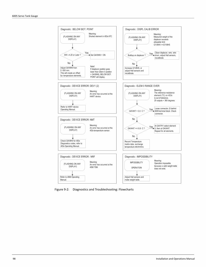
6005 Servo Tank Gauge
98 Installation and Operations Manual
Figure 9-2: Diagnostics and Troubleshooting: Flowcharts
Adjust G4V8H6 from0 -500 mm.This will create an offset for temperature elements.
(FLASHING ON ANYDISPLAY)
Meaning:Shorted element in 453x ATC
Meaning:An error has occurred at theHART device.
Refer to HART deviceOperating Manual.
Diagnostic : BELOW BOT. POINT
Diagnostic : DEVICE ERROR: DEV1 (2)
Diagnostic : DEVICE ERROR : NRF
Meaning:An error has occurred at the4590 TSM.
Refer to 4590 OperatingManual.
Diagnostic : DISPL CALIB ERROR
Increase G1V8H5, oradjust Hall sensors andrecalibrate.
Diagnostic : ELEM 0 RANGE OVERMeaning:The reference resistanceelement (ºC) on 453xis out of tolerance.20 outputs = 360 degrees.
Record Temperature matrix data, exchange temperature electronics.
Loose connector J3 behind6005 terminal block. Checkconnector.
G4V4H7 = 0.0 C ?
Meaning:Measured weight of thedisplacer exceedsallowable limit:G1V8H4 >=G1V8H5
SW v 4.20 or Later ? Set G4V9H8 = ON
Note!:If displacer position goeslower than (Elem 0 position+ G4V8H6), BELOW BOT.POINT will display.
(FLASHING ON ANYDISPLAY)
Meaning:An error has occurred at the453x temperature sensor.
Check G4V8H0 for 453xDiagnostics codes, refer to453x Operating Manual.
Diagnostic : DEVICE ERROR: NMT
(FLASHING ON ANYDISPLAY)
(FLASHING ON ANYDISPLAY)
(FLASHING ON ANYDISPLAY)
Buildup on displacer ?Clean displacer, wire, wiredrum, adjust Hall sensors,recalibrate.
(FLASHING ON ANYDISPLAY)
G4V4H7 <+/-9.9 C ?At G4V7H1 select element0, then at G4V4H7.Repeat for all elements.
Diagnostic : IMPOSSIBILITYMeaning:Operation impossiblebecause a valid weight tabledoes not exist.
Adjust Hall sensors andmake weight table.
IMPOSSIBILITY
OPERATION
Yes
No
Yes
No
Yes
Yes
No
No

Chapter 9 - Diagnosis and Troubleshooting
Varec, Inc. 99
Figure 9-3: Diagnostics and Troubleshooting: Flowcharts
Check HART bus wiring:
DEV to 6005 cut or short ?
DEV (+)(-) to 6005 (+)(-) ?
Voltage = DC16.5 - 25.5V ?
(FLASHING ON ANY
DISPLAY)
Meaning:
An error has occurred at the
HART device.
Diagnostic : LOCAL ERROR DEV1(2) Diagnostic : LOCAL ERROR NRF
Check HART bus wiring:
4560 to 6005 cut or short ?
6005 (+)(-) to 4560 (+)(-) ?
453x to 6005 cut or short ?
Voltage = DC16.5 - 25.5V ?
Meaning:
An error has occurred at the
4560 SGM.
G5V4H9 = ON ?
Set G5(6)V4H9 = ON
Check HART device
address with hand-held.
HART DEV1 = 4 (fixed)
HART DEV2 = 5 (fixed)
Meaning:
An error has occurred at the
453x temperature sensor.
Check G4V8H0 for 453x
Diagnostics codes, refer to
453x Operating Manual.
Diagnostic : LOCAL Error NMT
(FLASHING ON ANY
DISPLAY)
(FLASHING ON ANY
DISPLAY)
G3V6H1 correct ?Make correct setting at
G3V6H1.
Diagnostic : MEM ERROR
Exchange TCB module,
adjust Hall sensors,
recalibrate.
MEM. ERROR
YYMMDDhhmm TT ##
Yes
No
Yes
No
G5V4H9 = ON ?Refer to HART device
operating manual.
No
Check G3V6H1:
4560 >=v 1.82, CONTACT2
4560 < v 1.82, CONTACT1
OK ?
OK ?
Exchange FCB module in
4560.
Exchange POW module in
4560.
No
No
OK ?
Exchange electronics
module in 453x.
Check HART bus wiring:
4560 to 6005 cut or short ?
6005 (+)(-) to 453x (+)(-) ?
453x to 6005 cut or short ?
Voltage = DC16.5 - 25.5V ?
NoMeaning:
Power to the CPU module
fell below minimum value.
Diagnostic : MPU : RESET
OK ?
Noise, Isolate and eliminate
source of noise.
No
MEM. ERROR
YYMMDDhhmm TT ##
Frequent ?
Exchange TCB module,
adjust Hall sensors,
recalibrate.
No

6005 Servo Tank Gauge
100 Installation and Operations Manual
Figure 9-4: Diagnostics and Troubleshooting: Flowcharts
Check local power supply
if frequent.
MPU: START ACT
YYMMDDhhmm TT ##
Meaning:
Power supply has been
turned (off and) on.
Indicates normal operation.
RORRE MOR : citsongaiDTCA TRATS :UPM : citsongaiD
Meaning:
CPU ROM failure.
Meaning:
Tension on measuring wire
is more than value in
G1V6H3.
Set Operation = STOP
Set G3V7H1 = ON
Diagnostic : OVERTENSION
(FLASHING ON ANY
DISPLAY) Diagnostic : TEMP. BELOW RANGE
Check 6005 specification.
Check G4V5H0 thru H9.
Check temperature in tank.
Exchange TCB module,
adjust Hall sensor,
recalibrate.
Check measuring wire,
displacer, stilling pipe for
cause of overtension.
No
Meaning:
Open element in 453x ATC
temperature sensor.
Diagnostic : TEMP. COM. OPEN
OK ?
Enter correct number of
temperature elements at
G4V8H2.
G4V8H2 data correct ?
Record Temperature matrix
data, exchange temp.
electronics.
No
ROM ERROR
YYMMDDhhmm TT ##
Diagnostic : SIFA ERROR
Meaning:
CPU SIFA failure.
Exchange TCB module,
adjust Hall sensor,
recalibrate.
SIFA ERROR
YYMMDDhhmm TT ##
Measuring wire cut ?
Find and fix cause of cut
wire. Replace displacer,
adjust Hall sensor,
recalibrate.
Yes
Diagnostic : POWER FAILURE
POWER FAILURE
YYMMDDhhmm TT ##
Check local power supply.
Meaning:
Supply voltage has fallen
below about 95VAC.
Diagnostic : RAM FAILURE
Exchange TCB module,
adjust Hall sensors,
recalibrate.
RAM FAILURE
YYMMDDhhmm TT ##
Meaning:
CPU RAM failure.
Data below range ?
Record Temperature matrix
data, exchange temperature
electronics.
Normal operation. Error
will clear when actual
temperature is within
speciifi cation.
Meaning:
Measured temperature data
for one or more elements is
below fixed range of 453x
specification.
(FLASHING ON ANY
DISPLAY)
(FLASHING ON ANY
DISPLAY)
May require complete
453x exchange. Send all
Temperature matrix (G4)
data to Varec.
Yes
No
Yes
No

Chapter 9 - Diagnosis and Troubleshooting
Varec, Inc. 101
Figure 9-5: Diagnostics and Troubleshooting: Flowcharts
Enter correct number of
temperature elements at
G4V8H2.
Meaning:
Shorted element in 453x ATC
temperature sensor.
Diagnostic : TEMP. COM. SHORT
Meaning:
Measured temperature data
for or more elements is over
fixed range of 453x ATC
specification.
Check 453x ATC spec.
Check G4V5H0 thru H9.
Check temperature in
tank.
Diagnostic : TEMP. OVER RANGE
(FLASHING ON ANY
DISPLAY)
Diagnostic : UNDERTENTION
Set Operation = STOP
Set G3V7H1 = ON
Record Temperature matrix
data, exchange temperature
electronics.
No
Meaning:
Measured length of the
measuring wire exceeds
allowable limit:
G1V7H4 >= G1V7H5
Diagnostic : WIRE CALIB ERROR
Increase G1V8H5, or adjust
Hall sensors and recalibrate.
Buildup on
measuring wire ?
Clean displacer, wire, wire
drum, adjust Hall sensors,
recalibrate.
No
Data over range ?
Normal operation. Error
will clear when actual
temperature is within
specification.
Yes
Measuring wire cut ?
Check measuring wire,
displacer, stilling pipe for
cause of undertension.
Find and fix cause of cut
wire. Replace displacer,
adjust Hall sensors,
recalibrate.
Meaning:
Tension on measuring wire
is more less value in
G1V6H3.
(FLASHING ON ANY
DISPLAY)
(FLASHING ON ANY
DISPLAY)
Yes
No
Yes
(FLASHING ON ANY
DISPLAY)
G4V8H2 data correct ?
Record Temperature
matrix data, exchange
temperature electronics.
OK ?
May require complete
453x exchange. Send all
Temperature matrix (G4)
data to Varec
No
No
Yes
Meaning:
The Z-phase signal output
from the encoder, or input
to CPU, is abnormal.
1 output = 360 degrees.
Diagnostic : Z PHASE NO INPUT
Exchange detector unit,
adjust Hall sensors,
recalibrate.
TCB CN5, CN7 loose ? Make connections firm.
No
Z PHASE NO INPUT
YYMMDDhhmm TT ##
Yes
OK ?No

6005 Servo Tank Gauge
102 Installation and Operations Manual
Figure 9-6: Diagnostics and Troubleshooting: Flowcharts
Setting after Parts Replacement After any part of the 6005 STG has been replaced, and before starting the 6005 STG calibration, specify the data on the following equipment.
• Circumferential length of the wire drum (indicated on face of wire drum).• Weight of the displacer (indicated on the body of the displacer).• Volume of the displacer (indicated on the body of the displacer).• Balance volume (indicated on the body of the displacer or 50% of volume).• Density of measured liquid (up to three phases).• Height of the tank with the 6005 STG mounted on it (refer to section , "Tank Height
(GVH140)" on page 63).
After calibration G3V7H0 Measured Weight = 0.0 minus value.
Diagnostic : Calibration unsuccessful Diagnostic : No response to OPERATION
0.0g
MEASURED WEIGHT
G3V4H0, H1, H2
correct ?
Input correct values for
circumference, wire and
displacer weight, adjust
Hall sensors, recalibrate.
Adjust Hall sensors,
recalibrate. If G7V4H0
thru H4(any) = 0, and does
not respond to adjustment,
exchange detector unit.
No
No
Yes
Hall sensor
adjustment OK ?
G3V9H7
a = b = 65000 ?
Calibration OK ?
Exchange TCB module,
adjust Hall sensors and
recalibrate.
Forgot to pick up displacer
at step 3 of Weight Table
Recalibration. Repeat.
Exchange detector unit,
adjust Hall sensors and
recalibrate.
Yes
Yes
No
No
LEVEL
OPERATION
G0V2H4 = LEVEL ?At 4560 SGM
set OPERATION = LEVEL
No
No
Yes
G0V2H5 = LEVEL ?
EPROM OK in
TCB module
Operation OK ?
Exchange TCB module,
adjust Hall sensors and
recalibrate.
Inspect EPROM U2 in TCB
module. Straighten any
bent legs. EPROM should
be inserted firm and level
in socket.
Exchange detector unit,
adjust Hall sensors and
recalibrate.
Yes
No
G0V2H0 = LEVEL, G0V2H1 0 = (not LEVEL)
(not LEVEL)
OPERATION STATUS
G3V7H0
G3V4H2 (+/- 2g)?
Adjust Hall sensors and
recalibrate.
At host CPU and /or
interface set OPERATION
= LEVEL
No
No
Yes
G0V2H0 G0V2H0
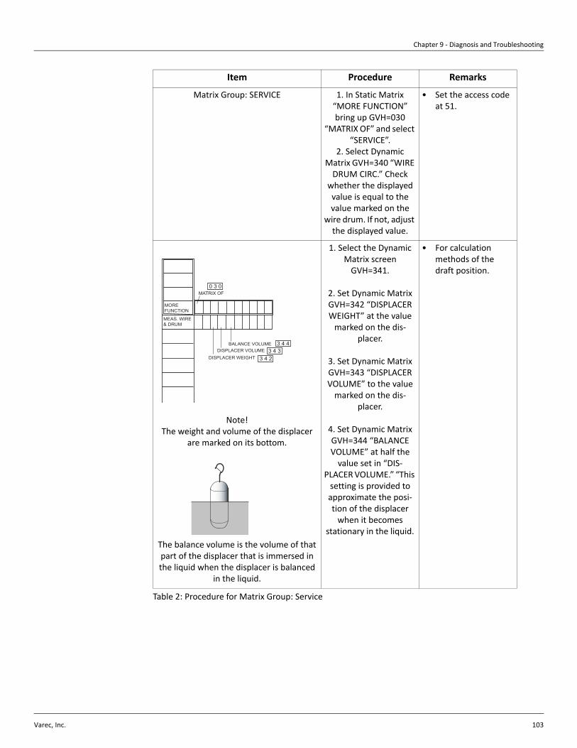
Chapter 9 - Diagnosis and Troubleshooting
Varec, Inc. 103
Table 2: Procedure for Matrix Group: Service
Item Procedure Remarks
Matrix Group: SERVICE 1. In Static Matrix “MORE FUNCTION” bring up GVH=030
“MATRIX OF” and select “SERVICE”.
2. Select Dynamic Matrix GVH=340 “WIRE
DRUM CIRC.” Check whether the displayed value is equal to the value marked on the
wire drum. If not, adjust the displayed value.
• Set the access code at 51.
Note!The weight and volume of the displacer
are marked on its bottom.
The balance volume is the volume of that part of the displacer that is immersed in the liquid when the displacer is balanced
in the liquid.
1. Select the Dynamic Matrix screen
GVH=341.
2. Set Dynamic Matrix GVH=342 “DISPLACER WEIGHT” at the value
marked on the dis-placer.
3. Set Dynamic Matrix GVH=343 “DISPLACER VOLUME” to the value
marked on the dis-placer.
4. Set Dynamic Matrix GVH=344 “BALANCE VOLUME” at half the
value set in “DIS-PLACER VOLUME.” “This
setting is provided to approximate the posi-tion of the displacer
when it becomesstationary in the liquid.
• For calculation methods of the draft position.
MOREFUNCTION
DISPLACER WEIGHT 3 4 2
MATRIX OF0 3 0
DISPLACER VOLUMEBALANCE VOLUME
3 4 33 4 4
MEAS. WIRE& DRUM

6005 Servo Tank Gauge
104 Installation and Operations Manual
Intelligent Function
Maintenance prediction function
The history of maintenance is displayed on the Matrix screen GVH=265 “(Parts Overused Date).” The LCD screen displays the following contents.
• Total operation time for parts managed according to this value• Total number of rotations of the wire drum for parts managed according to this value
Table 3: Reference Part Management Value
Spare Parts Spare parts are contained in kits. Spare parts that can be ordered from Varec for the 6005 STG are shown with their order numbers in section , "6005 STG Spare Parts List" on page 105 (Table 4). For more information on service and spare parts, contact Varec at (770) 447-9202.
Reference Part
Management Value
Display Part
Reference
(conducting time/
number of rotations)
1) POWER UNIT
2) DISPLAY UNIT
3) MOTOR UNIT
4) WIRE UNIT
5) BEARINGS UNIT
6) SHAFT UNIT
Power supply unit
LCD indicator
Motor/driver unit
Measuring wire
Drum bearing metal
Drum shaft
43,800 hours (about 5 years)
61,300 hours (about 7 years)
43,800 hours (about 5 years)
240,000 rotations
145,000 rotations
240,000 rotations

Chapter 9 - Diagnosis and Troubleshooting
Varec, Inc. 105
6005 STG Spare Parts
Figure 9-7: 6005 STG Spare Parts
6005 STG Spare Parts List
Follows on the next two pages.
T-AMP
Zone 0 NMS5-2/5-5/5-6
NMS5-2/5-5/5-6
NMS5-1/5-4
Accessories
11
1111
21
21
21
21
31
32
33
34 35
36
37
37
37
42
43
44
51
52
52
52
52
52
53
53
53
cable between terminal and module
Wire HookWelding Part
Bottom of Tank

6005 Servo Tank Gauge
106 Installation and Operations Manual
Alu
min
um D
rum
Hou
sing
Dru
m H
ousi
ngC
alib
ratio
n W
indo
w
Order Code Parts Name Order Code Parts Name11 Oring 70106039 Upgrade kit HART active output
017803-0034 O-ring, cover drum housing Alu, NBR 56004534 Communication module WM550, arrestor
70106019 O-ring, cover drum housing Alu, CR 52013662 Upgrade kit WM550
70106020 O-ring, cover drum housing Alu, FKM 56004409 Communication module Mark Space
70106021 O-ring, cover drum housing Alu, Silicon 52013658 Upgrade kit Mark Space
56004345 O-ring, cover drum housing Alu, PTFE 56004355 Communication module ENRAF BPM, COM-
017803-0066 O-ring, cover drum housing, SS, FKM 52013649 Upgrade kit Enraf BPM
017803-0035 O-ring, cover drum housing, SS, silicone 34 Electronic Module, Contact Output70109105 O-ring, cover drum housing, SS, NBR 017800-0007Alarm output, 2x contact, I/O 3
70109106 O-ring, cover drum housing, D158-d3.5 CR 70109108 Alarm output, 2x contact, I/O 3, TUV OSP
70109107 O-ring, cover drum housing, D158-d3.5 PFA 52013654 Upgrade kit I/O-3
017803-0033 O-ring, calibration window, NBR 35 Electronic Module, A/O70106018 4BCT ,5 O/I ,Am02-4 tuptuO7100-008710RC ,wodniw noitarbilac ,gnir-O
017803-0041 O-ring, calibration window, silicone 52013656 Upgrade kit I/O-5
017803-0036 O-ring, calibration window, FKM 36 Electronic Module, Ex [ia] HART Communication
56004518 O-ring, calibration window, PTFE 56004356 Communication module EXI HART, COM-4
017803-0030 O-ring, display cover, NBR 37 Electronic Module, I/O Spot Temperature Input017803-0040 erutarepmet tops ,.O.C/.I .repO24440065RBN ,revoc lanimret ,gnir-O
71070894 PTFE packin+ring, calibr. window, Zone0 70106035 Upgrade kit oper. I./C.O., Ex d temp.
21 Cover 70106032 Upgrade kit oper. input/contact out
017800-0111 Cover, display module, Aluminium 56004441 Operation input/contact out, carrier
017800-0112 Cover, terminal box, Aluminum, NMS 56004491 Spot temp. with Chassis
017800-0113 Cover, drum housing, Alu, NMS531/NMS534 56004490 Spot temp. input T-AMP UP grade KIT
56004307 Cover, drum housing, SS, NMS535/536 70106027 Spot temp. Ex ia, carrier
56004308 Cover, drum housing, SS, NMS532 40 Fuse56004295 Calibration window, Alu, NMS531/NMS534 70106027 Fuse 250VAC T2A50, NMS, 10 pcs.
56004296 Calibration window, SS, NMS532/NMS535 70106499 Fuse 20-62VDC T3A15, NMS, 10 pcs.
56004297 Calibration window, SS, NMS536 70106500 Fuse cover 10set, NMS
71070909 Calibration window, SS, Zone 0, NMS532/535/536 41 Connector, Cable31 Electronic Module, Power Module 52013660 Wiring harness,Ter.-COM-1/RS485/BPM mod.
.dom evissap TRAH-.mreT ,ssenrah gniriW05631025i xE non ,VH ,6-WOP04930107
.dom evitca TRAH-.mreT ,ssenrah gniriW73060107i xE ,VH ,6-WOP24930107
.dom ecapS kraM-lanimreT ,ssenrah gniriW75631025i xE non ,VL ,6-WOP14930107
.dom MPB FARNE-lanimreT ,ssenrah gniriW84631025i xE ,VL ,6-WOP34930107
32 Electronic Module, Main CPU 52013653 Wiring harness, Terminal-I/O-3 module
70103937 TCB-6, CPU module, upgrade of TCB-4 52013652 Wiring harness I/O-3-TCB
33 Electronic Module, Remote Communication 52013655 Wiring harness, Terminal-I/O-5 module.
70103937 COM-1, Communication module, V1 70106036 Wiring harness, Terminal-COM-4 module
52013661 Upgrade kit V1 70106033 CPU, T-AMP Ex d module cable
.dom d xE PMA-T-lanimreT,ssenrah gniriW430601075-MOC ,584SR eludom subdoM36768017
.dom ai xE PMA-T-lanimreT,ssenrah gniriW69950107584SR subdoM tik edargpU07260107
56004484 COM-6 HART, passive remote commu. module 70105995 CPU, T-AMP Ex ia module cable
52013651 42 Terminal8054006558440065
56004509

Chapter 9 - Diagnosis and Troubleshooting
Varec, Inc. 107
Order Code Prts Name Order Code Parts Name43 Chasis017800-0015 PCB CPU Carrier set complete, spacer 56004257 5x measuring wire, 28m, d=0.15mm, 316L
017800-0021 Display module 2line, 3key optical 5x measuring wire, 16m, d=0.2mm, Alloy C
70103938 Display module 4line, 3key optical 56004914 Measuring wire, 0.2mm, AlloyC, 16m
56004256 5x measuring wire, 16m, d=0.4mm, PTFE
017800-0043 Detector unit NMS, TCC-3 56004912 Measuring wire, 0.4mm, PTFE coated, 16m
70103944 Detector unit NMS, TCC-3, V1 017800-0241 Wire ring, 316
017800-0242 Wire ring, PTFE coated
CyollA ,gnir eriW2520-0087103420-008710m82 ,.seM eriw + murd eriW32540065
56004524 017800-0252 Displacer, 50mm, cylindrical, SUS316
gnir ediug ,lacirdnilyc ,mm05 ,recalpsiD93340065m61 ,yollA eriw ,murd eriW02540065
dilos EFTP ,lacinoc ,mm05 ,recalpsiD3520-008710RC ,eriw m82 ,murd eriW40441117
dilos EFTP ,lacirdnilyc ,mm05 ,recalpsiD49950107enocilis ,eriw m82 ,murd eriW50441117
71114406 017800-0271 Displacer, 50mm, cylindrical, AlloyC
71114407 Displacer, 70mm, conical, SUS316, NMi
71114408 Wire drum, 16m AlloyC wire, CR 017800-0267 Displacer, 110mm, conical, SUS316, low
71114409 Wire drum, 16m AlloyC wire, silicone 70104684 Displacer, 110mm, conical, 316, high
71133077 Wire drum + 36m wire, SUS316L 71083820 Displacer, 50mm, cylindrical, 316, Zone0
71133079 Wire drum + 36m wire SUS316L, CR 71134069 Displacer, 30mm, cylindrical, 316, Zone0
71133078 Wire drum + 36m wire SUS316L, Silicone 71134070 Displacer, 40mm, cylindrical, 316, Zone0
0enoZ ,613,.dnilyc ,mm05 ,gnir ,recalpsiD17043117.eriw m74 + murd eriW99043117
0enoZ ,613,.dnilyc ,mm07 ,gnir ,recalpsiD76043117.RC ,eriw m74 + murd eriW00143117
0enoZ ,613,.dnilyc ,mm011 ,gnir ,recalpsiDenociliS ,eriw m74 + murd eriW10143117
0enoZ ,CyollA ,.dnilyc ,mm05 ,recalpsiDulA ,tekcarb murd eriW52540065
56004527 Wire drum bracket, SS
56004526 71067825 Calibration weight 50gr, NMS5
017800-0221 Bearing, wire drum bracket, PTFE 71134095 Wire hook, SUS, L=100
Wire hook, SS400, L=100
71114403 Measuring wire 0.15mm 28m SUS316L, ring SUS44 Display Module
51 Detector, Servo Unit
52 Wire Drum
53 Measuring Wire, Displacer
56004255
017800-0263
71134068
71134072
75 Accessory
71134096

6005 Servo Tank Gauge
108 Installation and Operations Manual
Return The following procedures must be carried out before the instruments is sent to Varec for repair:
• Always enclose a duly completed “Declaration of Contamination” form. Only then can Varec transport, examine, and repair a returned device.
• Enclose special handling instructions if necessary, for example, safety data sheet as per EN 91/155/EEC.
• Remove all residue which may be present. Pay special attention to the gasket grooves and crevices where fluid may be present. This is especially important if the fluid is dangerous to health, e.g. corrosive, poisonous, carcinogenic, radioactive, etc.
A copy of the “Declaration of Contamination” is included at the end of this operating manual.
Caution No instrument should be sent back for repair without all dangerous material being completely removed first, e.g. in scratches or diffused through plastic.
Caution Incomplete cleaning of the instrument may result in waste disposal or cause harm to personnel (burns, etc.). Any costs arising from this will be charged to the operator of the instrument.
Disposal In case of disposal, please separate the different components according to their material consistency.
Gauge Software
Software version / Date Software changes Documentation changes
V2.13, from 9.96 Original Release BA001N/08/en/09.98
V2.20, from 10.97 T2:TCB-2, Modified V1: R&S command BA001N/08/en/11.97
V4.06, from 04.98 HART master, T4:TCB-4
V4.06, from 04.98 HART master T&W, T4:TCB-4
V4.08X, from 08.98 Upper stop speed reduction 3-step
V4.20, from 08.98 WM550, Commuwin II display, elem. Error fix BA001N/08/en/12.99
V4.20, from 09.98 T&W BA001N/08/en/12.99

Chapter 9 - Diagnosis and Troubleshooting
Varec, Inc. 109
Table 4: Gauge Software
Contact Addresses of Varec The address of Varec is displayed on the back cover of this operating manual. If you have any questions, please do not hesitate to contact your Varec at:
Varec, Inc. 5834 Peachtree Corners East Peachtree Corners (Atlanta), Georgia 30092 Phone: (770) 447-9202 Fax: (770) 662-8939
V4.22, from 05.00 HART line selectionAdd to static matrix: gas temp.Minus data remote communicationLevel 6 digit data processingMemory clear Volume calculation matrix deleted
V4.23B, from 09.00 Standard release, alarm output modify, 453x ATC level selection
V4.24, from 04.01 Standard release IOM007NVAE1103
V4.24 OSP, from 06.01 Over Spill protection
V4.24T&W, from 07.01 T&W spec.
V4.24 T2, from 02.02 TCB-2 CPU, 453x ATC, V1 level measurement
V4.25, from 09.02 Density profile function BA001N/08/en/02.02
V4.27, from 09.04 Level hold matrix, Error display on Home screen only
V4.27 T6/T&O, from11.05 W&M and Overspill prevention IOM007NVAE0908
V4.27 A, from 05.07 standard release
V4.27 B, from 09.08 standard release BA1001N/08/en/12.08
V4.27 C, from 04.09 Proactive Safety function IOM007NVAE0210
V4.27 F, from 05.11 SIL IOM007NVAE5011
VF.27 G, from 05.12 4-20mA long range support IOM007NVAE4213
Software version / Date Software changes Documentation changes

6005 Servo Tank Gauge
110 Installation and Operations Manual

Varec, Inc. 111
Chapter 10
Displacer and Measuring Wire
Shape, Diameter, and Material
Displacer
There are several types of displacers available for the 6005 STG:
• The standard type has cylindrical shape and a diameter of 50 mm. Diameters from 30 to 50 mm are optional.
• The cylindrical shape is used for viscous liquids. It is also effective if the stilling well is not smooth on its interior surface.
Displacer weight and volume depend on the application. Thin displacers are suited for level measurement, thicker ones for bottom level, interface level, and density measurement.
A counterweight is optional for heavy turbulence (please inquire).
Displacers of three different materials are provided:
• The standard material is stainless steel SUS316.• Alloy C and PFA are optional for corrosive liquids.• Solid PFA, however, is not applied for flammable liquids.
The following size of displacer will be supplied, when custody transfer approval is ordered.
• NMi (Netherlands).................∅70mm
Measuring Wire
• The standard material of the measuring wire is stainless steel SUS316 (∅0.15 mm).• AlloyC (∅0.20 mm) and PFA coated stainless steel SUS316 (∅0.4 mm) are for
corrosive liquids.
The following specification of measuring will be supplied when the custody transfer approval is ordered.
• SUS316 (∅0.15 mm) for NMi
Refer to section , "Displacer" on page 6 of this manual.

6005 Servo Tank Gauge
112 Installation and Operations Manual
Alarm History Display
Table 1: Alarm Display History
Item Procedure Remarks
Matrix Group: DEVICE DATA
Touch Control
1. 1. Bring up Static Matrix GVH=034 *ALARM CONTACT.”
Static Matrix2. Previous static matrix
records are sequentially displayed in Static Matrix screen GVH=035, starting with the latest record. Up to 100 alarm records can be saved. If the number of records exceeds 100, it is sequentially overwritten starting with the oldest record. The display includes the year, month, day, hour, minute, instrument tempera-ture, and an error sequential number, in this order. For example, 97 3192238 2402 means that an error occurred at 22:38 on March 19, 1997, when the instru-ment temperature was 24 oC and this is the second error since 6005 STG was installed.
MOREFUNCTION
ALARM CONTACT0 3 4
MOREFUNCTION
(Alarm Message)0 3 5
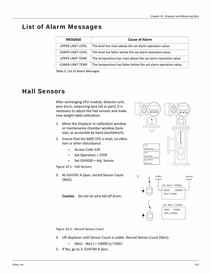
Chapter 10 - Displacer and Measuring Wire
Varec, Inc. 113
List of Alarm Messages
Table 2: List of Alarm Messages
Hall Sensors After exchanging CPU module, detector unit, wire drum, measuring wire (all or part), it is necessary to adjust the Hall sensors and make new weight table calibration.
1. Move the Displacer in calibration window or maintenance chamber window (tank-top), or accessible by hand (workbench).
2. Ensure that the 6005 STG is level, no vibra-tion or other disturbance.
• Access Code 530• Set Operation = STOP• Set GVH030 = Adj. Sensor
Figure 10-1: Hall Sensors
3. At GVH741 A Span, record Sensor Count (Wa2).
Caution Do not let wire fall off drum.
Figure 10-2: Record Sensor Count
4. Lift displacer until Sensor Count is stable. Record Sensor Count (Wa1).
• |Wa2 - Wa1 | = 10000 (+/-100)?5. If Yes, go to 3. GVH740 A Zero.
MESSAGE Cause of Alarm
UPPER LIMIT LEVEL The level has risen above the set alarm operation value.
LOWER LIMIT LEVEL The level has fallen below the set alarm operation value.
UPPER LIMIT TEMP. The temperature has risen above the set alarm operation value.
LOWER LIMIT TEMP. The temperature has fallen below the set alarm operation value.
530
ACCESS CODE
STOP
OPERATION
ADJ. SENSOR
MATRIX OF
29XX 25000ADJ. A SPAN
2. index count
sensor count
(Ex. Wa2 = 25000)
29XX 15000
ADJ. A SPAN
(Ex. Wa1 = 15000)

6005 Servo Tank Gauge
114 Installation and Operations Manual
6. If No, release displacer. At GVH741
• If |Wa2 - Wa1 |<10,000, increase Index Count.• If |Wa2 - Wa1 |>10,000, decrease Index Count.• Repeat until |Wa2 - Wa1 | = 10000 (+/-100).
7. Adjust GVH740 A Zero Sensor Count
= 21000 (+/-100)
8. Recode Sensor counter (Wa2)
9. Lift displacer until Sensor Count is stable. Record Sensor Count (Wa2).
• |Wa1 - Wa2 | = 10000 (+/-100)?
Figure 10-3: Adjust GVH740 A at Zero Sensor Count
10. If yes, go to 4. GVH743
11. If no, repeat 2 and 3.
12. At GVH743 B Span, repeat steps above.
13. Adjust GVH742 B Zero Sensor Count = 11000 (+/- 100)
Figure 10-4: Adjust GVH742 B at Zero Sensor Count
29XX 21000
ADJ. A ZERO
(Ex. Wa2 = 2100)
(Ex. Wa1 = 1100)
29XX 11000
ADJ. A ZERO
31XX 11000
ADJ. B SPAN
31XX 21000
ADJ. B SPAN
(Ex. Wa1 = 1100)
31XX 21000ADJ. B SPAN

Chapter 10 - Displacer and Measuring Wire
Varec, Inc. 115
Initial Weight Calibration
Displacer weight calibration — level measurement function only
Weight table calibration must be done after Hall sensor adjustment. Use this procedure only for STGs with level measurement function only.
Note Wind and vibration affect weight table calibration. Not necessary to make Initial Calibration for Startup “All-in-one” (displacer attached) shipments.
Item Procedure Remarks
Weight table calibration, Basic. 1. Enter Access Code 51.
2. Confirm the follow-ing data.
• G3V4H0 wire Drum Circum.(engraved on wire drum)
• G3V4H1 Wire Weight Standard SUS = 1.40
• PFA=4.55 • Hastelloy=2.8 • G3V4H2 Displacer
Weight (engraved on displacer)
3. Displacer is in calibration window or maintenance chamber.
• Set Operation = STOP• Set G3V7H9=0.0 • Set G3V7H3=ON
At “Displacer Down? +/-"Enter NO(-).However, for maintenance chamber enter Yes (+).
e.g.300.110
e.g.250.2 g
HV 0 1 2
4 xxx.xxx x.xx xxx.x
ServiceMatrix: G3
Wire Drum Displacer
51ACCESS CODE
e.g.
+
-
STOPOPERATION
ONWEIGHT CALIB.
Displacer down?
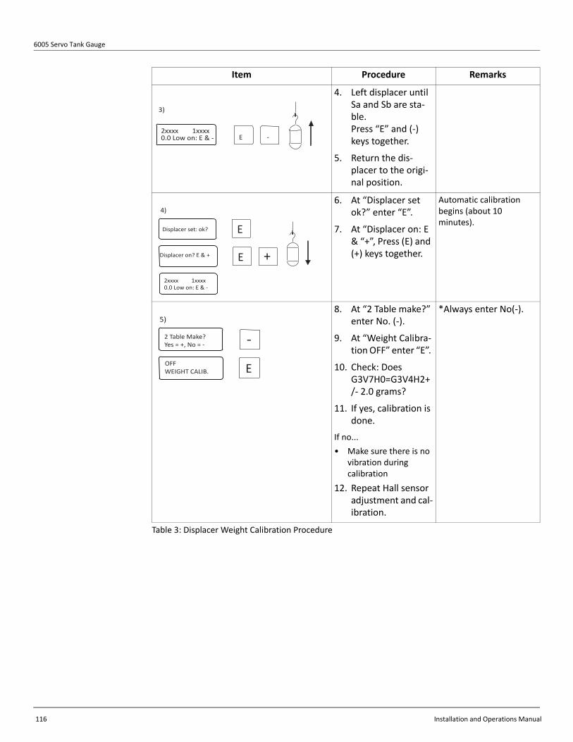
6005 Servo Tank Gauge
116 Installation and Operations Manual
Table 3: Displacer Weight Calibration Procedure
4. Left displacer until Sa and Sb are sta-ble. Press “E” and (-) keys together.
5. Return the dis-placer to the origi-nal position.
6. At “Displacer set ok?” enter “E”.
7. At “Displacer on: E & “+”, Press (E) and (+) keys together.
Automatic calibration begins (about 10 minutes).
8. At “2 Table make?” enter No. (-).
9. At “Weight Calibra-tion OFF” enter “E”.
10. Check: Does G3V7H0=G3V4H2+/- 2.0 grams?
11. If yes, calibration is done.
If no...• Make sure there is no
vibration during calibration
12. Repeat Hall sensor adjustment and cal-ibration.
*Always enter No(-).
Item Procedure Remarks
-E2xxxx 1xxxx0.0 Low on: E & -
3)
E
E +
Displacer set: ok?
Displacer on? E & +
2xxxx 1xxxx0.0 Low on: E & -
4)
-2 Table Make?Yes = +, No = -
OFFWEIGHT CALIB. E
5)

Chapter 10 - Displacer and Measuring Wire
Varec, Inc. 117
Displacer Weight Calibration
Weight table calibration must be done after Hall sensor adjustment. Use this procedure for STGs with level, density, and/or interface measurement function.
Note Wind and vibration affect weight table calibration. Not necessary to make Initial Calibration for Startup “All-in-one” (displacer attached) shipments.
Item Procedure Remarks
Weight table calibration, Density. 1. Enter Access Code 51 confirm the following data.
• G3V4H0 wire Drum Circum.(engraved on wire drum)
• G3V4H1 Wire Weight Standard
• SUS = 1.40• PFA=4.55• Hastelloy=2.48• G3V4H2
Displacer Weight (engraved on displacer)
• G3V7H9 Zero Adjust Weight=e.g. 50.2
2. Displacer is in calibration window or maintenance chamber.
• Set Operation = STOP• Set G3V7H9=e.g.
50.2g (test weight, in grams)
• Set G3V7H3 Weight Calib. =ON
At “Low weight set?”... enter No (-). However, for maintenance chamber, enter Yes (+).
e.g.300.110
e.g.250.2 g
HV 0 1 2
4 xxx.xxx x.xx xxx.x
ServiceMatrix: G3
Wire Drum Displacer
51ACCESS CODE
HV
7
9
50.2
50.x gweight
e.g.
+
-
STOPOPERATION
ONWEIGHT CALIB.
Displacer down?
2)

6005 Servo Tank Gauge
118 Installation and Operations Manual
Table 4: Displacer Weight Calibration Procedure
3. Replace displacer with 50 x g weight, stabi-lize weight.
4. Press “E” and (-) key together.
5. Replace displacer on wire.
6. At “Displacer on: E & “+”, press “E” and (+) keys together.
Automatic calibration begins (about 10 minutes).
7. 5) Check: Does G3V7H2 +/- 2.0 grams?
• If yes, calibration is done.
• If no...-make sure there is no vibration during calibration
8. Repeat Hall sensor adjustment and cal-ibration.
Item Procedure Remarks
e.g.
3)
51ACCESS CODE -E
2xxxx 1xxxx50. x Low on: E & -
e.g.
4)
-E
EDisplacer set: ok?
Displacer on: E & +
Sa 21000 A 21000Sb 11000 B 11000
-
E
2 Table Make?Yes = +, No = -
OFFWEIGHT CALIB.
5)
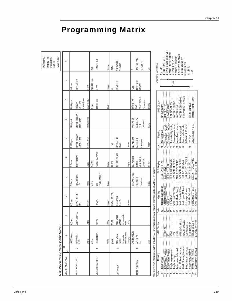
Varec, Inc. 119
Chapter 11
Programming Matrix
01
23
45
67
89
0 1 2 3
VH
6005
Pro
gram
ming
Matr
ix (S
tatic
Matrix
)GR
OUP
MESS
AGE
Disp
lay Te
xtPa
ramete
rs,un
it, etc
Defau
lt Data
MEAS
URED
VAL
UE 1
MEAS
URED
VAL
UE 2
OPER
ATIO
N
MORE
FUNC
TION
1600
0.00m
m
MEAS
URED
LE
VEL
Disp
lay
0.0 m
m
ULLA
GE LE
VEL
0.0°C
LIQUI
D TE
MP.
Disp
lay
STOP
OPER
ATIO
N 16
000
See o
perat
ionco
mman
ds be
lowSe
lect (5
0)
CALIB
RATIO
NMA
TRIX
OF
Selec
t
Disp
lay
See s
tatus
table
be
low
OPER
ATIN
G ST
ATUS
STOP
Disp
lay
DEV(
1)
Disp
lay
0.0 m
m0.0
mm
UPPE
R IN
TERF
.LE
V.
Disp
lay
DEV(
2)
Disp
layDi
splay
UNBA
LANC
ED
BALA
NCIN
G ST
ATUS
Disp
lay
MIDD
. INTE
RF.
LEV
Disp
layDi
splay
BOTT
OM LE
VEL
0.0 m
m
0.0°C
GAS
TEMP
ERAT
URE
LEVE
LLE
VEL
OPER
AT.B
Y NR
F
Disp
layDi
splay
98 62
7 8:21
:00CA
LEND
ERCu
rrent
data
Disp
layDi
splay
Disp
lay
Curre
nt da
taCu
rrent
data
ALAR
M CO
NTAC
T 0
NO A
LARM
NO A
LARM
LA 0
0 0
0
OPER
AT. B
Y HO
ST
1.000
g/ml
UPPE
R DE
NSITY
0.000
- 3.00
0
Disp
lay/S
et (50
)
1.000
g/ml
MIDD
LE D
ENSI
TY0.0
00 - 3
.000
DENS
ITY
BOTT
OM
1.000
g/ml
0.000
- 3.00
0
Disp
lay/S
et (50
)Di
splay
/Set
(50)
0 mm
ZERO
POI
NT
Disp
lay
NO E
RROR
DIAG
NOST
IC
CO 0
Curre
nt da
taCu
rrent
data
Disp
layDi
splay
98 62
7 752
0 0
MPU:
STAR
T AC
T0 AC
CESS
COD
E
0, 50
, 51,
777
Set
084
24
DEVI
CE ID
SOFT
WAR
E VE
RSIO
N
Disp
layDi
splay
SPAN
LENG
TH U
NIT
mm16
000.0
mm
0.0 m
m
LEVE
L DAT
A
Disp
lay
WAT
ER B
OTTO
M
0.0 m
m
Disp
lay
Whe
n new
NMS
statu
s is s
electe
d at G
VH=2
72, n
ew st
atus c
odes
are s
howe
d at m
atrix
posit
ion G
VH=0
21 as
follo
ws;
Code
Mean
ingNM
S Di
splay
Code
Mean
ingNM
S Di
splay
0 1 2 3 4 5 6 7 8 9 10
No de
finitio
nDi
splac
er at
refer
ence
Disp
lacer
hoist
ing up
Disp
lacer
going
down
Disp
lacer
stop
Leve
l mea
s. ba
lance
dUp
p. I/F
leve
l, bala
nced
Midd
. I/F
level,
balan
ced
Botto
m me
as. b
alanc
edUp
per D
ens,
finish
edMi
ddle
Dens
, finis
hed
REFE
RENC
EUP DO
WNST
OPLE
VEL
UPPE
R.IN
TERF
.LEV.
MIDD
.INTE
RF.LE
V.BO
TTOM
LEVE
LUP
PER
DENS
ITYMI
DDLE
DEN
SITY
12 13 14 15 16 17 18 19 20 21
Relea
se ov
er te
nsion
Calib
ratio
n acti
vated
Seek
leve
lFo
llow
level
Seek
Upp
er D
ensit
ySe
ek M
iddle
Dens
itySe
ek D
ensit
y Bott
omSe
ek U
pper
I/F le
vel
Follo
w up
. I/F
level
Seek
Mid.
I/F le
vel
RELE
. OVE
R TE
NS.
CAL.
ACTI
VELE
VEL S
EEKI
NGLE
VEL F
OLLO
WIN
GUP
P. DE
N. S
EEKI
NGMI
D. D
EN S
EEKI
NGBO
T. DE
N. S
EEKI
NGUP
P. IN
T. SE
EKIN
GUP
P. IN
T. FO
LLOW
ING
MID.
INT.S
EEKI
NG
-24 25 26 27 28 29 30 31 32Co
deMe
aning
NMS
Disp
layNo
t initia
lised
St
oppe
d at H
igh S
topSt
oppe
d at L
ow S
topRe
peata
bility
testi
ngSe
eking
wate
r leve
lW
ater le
vel, b
alanc
edFo
llow
water
leve
lOv
er-/U
nder
tens
ion,
Z-Ph
ase,
ADC
erro
r
NO IN
ITIA
LIZE
UPPE
R ST
OPLO
WER
STO
PRE
PEAT
ABILI
TYW
ATER
SEE
KING
WAT
ER LE
VEL
WAT
ER F
OLLO
WIN
GEM
ERGE
NCY
ERRO
R
Oper
ating
comm
ands
2.
STO
P 3.
BOT
TOM
LEVE
L 4.
UPP
ER IN
TERF
. LEV
EL 5.
MID
D. IN
TERF
. LEV
EL 6.
UPP
ER D
ENSI
TY 7.
MID
DLE
DENS
ITY
8. D
ENSI
TY B
OTTO
M 9.
REP
EATA
BILIT
Y10
.WAT
ER D
IP 0
. LEV
EL 1
. UP
+ Ke
y
Mode
(Cod
e)
OFF
RESE
T ALM
. DI
AGNO
.0 -
8
GVH1
57
Servi
ce M
ode =
ON,
MAIN
TENA
NCE
(Mod
bus /
HAR
T on
ly)11
Botto
m De
ns, fi
nishe
dDE
NSIT
Y BO
TTOM
22 23Fo
llow
Mid.
I/F le
vel
Seek
Bott
om le
vel
MID.
INT.
FOLL
OWIN
GBO
TTOM
SEE
KING
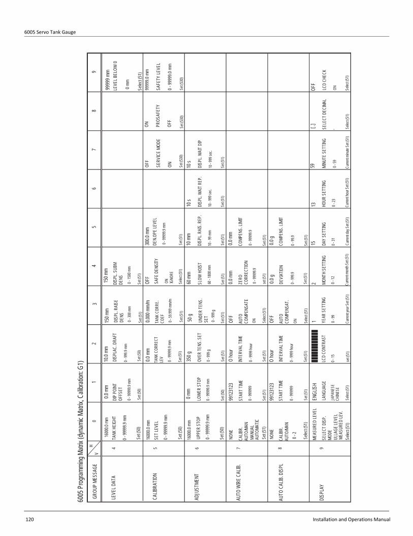
6005 Servo Tank Gauge
120 Installation and Operations Manual
6005
Prog
rammi
ng M
atrix
(dyna
mic M
atrix,
Cali
bratio
n: G1
)
01
23
45
67
89
4 5 6 7 8
29
,
VH
GROU
P ME
SSAG
E
LEVE
L DAT
A
CALIB
RATIO
N
ADJU
STME
NT
AUTO
WIR
E CA
LIB.
AUTO
CAL
IB. D
ISPL
DISP
LAY
1600
0.0 m
mTA
NK H
EIGH
T
0 - 99
999.9
mm
Set (5
0)
0.0 m
mDI
P PO
INT
OFFS
ET
0 - 99
999.9
mm
Set (5
0)
1600
0.0 m
mSE
T LEV
EL
0 - 99
999.9
mm
Set (5
0)
UPPE
R ST
OP
1600
0.0 m
m
0 - 99
999.9
mm
Set (5
0)
NONE
CALIB
R.
AUTO
/MAN
MANU
ALAU
TOMA
TICSe
t (51)
NONE
CALIB
R.
AUTO
/MAN
0 - 2
Selec
t (51)
MEAS
URED
LEVE
L
SELE
CT D
ISP.
MO
DEUL
LAGE
LEVE
LME
ASUR
ED LE
V.Se
lect (5
1)
0 mm
LOW
ER S
TOP
0 - 99
999.9
mm
Set (5
0)
10.0
mmDI
SPLA
C. D
RAFT
0 - 99
9.9 m
m
Set (5
0)
0.0 m
mTA
NK C
ORRE
CT
LEV
0 - 99
999.9
mm
Set (5
1)
350 g
OVER
TENS
. SET
0 - 99
9 g
Set (5
1)
9912
3123
STAR
T TIM
E
0 - 99
9999
Set (5
1)
O ho
ur
INTE
RVAL
TIME
0 - 99
99 ho
ur
Set (5
1)
9912
3123
STAR
T TIM
E
0 - 99
9999
Set (5
1)
ENGL
ISH
LANG
UAGE
JAPA
NESE
Selec
t (51)
set (5
1)
0 - 15
LCD
CONT
RAST
Set (5
1)
0 - 99
99 ho
ur
INTE
RVAL
TIME
O ho
ur
150 m
mDI
SPL.
RAIS
E DE
NS0 -
300 m
m
Set (5
1)
150 m
mDI
SPL.
SUBM
DE
NS0 -
1500
mm
Set (5
1)
0.000
mm/
mTA
NK C
ORRE
. CO
EF0 -
59.99
9 mm/
m
Set (5
1)
50 g
UNDE
R TE
NS.
SET
0 - 99
9 g
Set (5
1)
60 m
m
SLOW
HOI
ST
60 - 1
800 m
m
Set (5
1)
10 m
m
DISP
L. RA
IS. R
EP.
10 - 9
9 mm
OFF
AUTO
CO
MPEN
SATE
ON Selec
t (51)
OFF
AUTO
CO
MPEN
SAT.
ON Selec
t (51)
1 Curre
nt ye
ar Se
t (51)
0 - 99
YEAR
SET
TING
MONT
H SE
TTIN
G
0 - 12
Curre
nt mo
nth S
et (51
)
0.0 g
DEVI
ATIO
N
0 - 99
9.9
Set (5
1)
0.0 m
m
ZERO
CO
RREC
TION
0 - 99
999.9
set (5
1)
15 DAY
SETT
ING
0 - 31
Curre
nt da
y Set
(51)
0.0 g
COMP
ENS.
LIMI
T
0 - 9
9.9
Set (5
1)
Set (5
1)
0 - 99
999.9
COMP
ENS.
LIMI
T
0.0 m
mSe
t (51)
10 s
DISP
L. W
AIT R
EP.
10 - 9
99 se
c.
Set (5
1)Se
t (51)
10 - 9
99 se
c.
DISP
L. W
AIT D
IP
10 s
13 HOUR
SET
TING
0 - 23
Curre
nt ho
ur Se
t (51)
59 MINU
TE S
ETTIN
G
0 - 59
Curre
nt mi
nute
Set (5
1)Se
lect (5
1)
[ .] SELE
CT D
ECIM
AL
OFF
LCD
CHEC
K
ON Selec
t (51)
OFF
SAFE
DEN
SITY
ON IGNO
RE
300.0
mm
DEN.
OPE
LEVE
L
0 - 99
999.9
mm
Set (5
1)Se
lect (5
1)
9999
9 mm
LEVE
L BEL
OW 0
0 mm
CHIN
ESE
Selec
t (51
)OF
F
SERV
ICE
MODE
ON
ON PROS
AFET
Y
OFF
9999
9.0 m
m
SAFE
TY LE
VEL
0 - 99
999.0
mm
Set (5
30)
Set (5
30)
Set (5
30)

Chapter 11 - Programming Matrix
Varec, Inc. 121
01
23
45
67
89
4 5 6 7 8 9
VH
6005
Prog
rammi
ng M
atrix
(Dyn
amic
Matrix
, Dev
ice D
ata : G
2)
GROU
P ME
SSAG
E
CONT
ACT O
UTPU
T
ANAL
OG O
UT.
ADJU
ST
PART
S DA
TA
INPU
T SIG
NAL
COMM
UNIC
ATIO
N
STAT
US
SELE
CT. R
ELAY
1 Max 4
Selec
t (50)
NONE
ASSI
GN O
UTPU
T 1
LEVE
LLIQ
UID
TEMP
.
Selec
t (51)
1 PART
S NU
MBER
Max 1
0
Selec
t (51)
NONE
OPE.
CON
TACT
ACTIV
ATED
Selec
t (51)
HIGH
LEVE
L ALA
RM 1
LOW
NONE
Selec
t (51)
O s
STAT
US1 D
ELAY
to 99
s
Set (5
1)
NONE
ASSI
GN R
ELAY
LEV.
, LIQ
UID
TEMP
.,CA
UTIO
N, W
ARNI
NG,
EMER
GENC
Y ER
R.
Selec
t (50)
0 mm
0 mm
ADJU
ST 4m
AFO
R LIQ
UID
TEMP
.
Set (5
1)
ADJU
ST 20
mA
FOR
LIQUI
D TE
MP.
Set (5
1)
HIGH
RELA
Y FU
NCTIO
N
LOW
Selec
t (50)
0 mm
SWITC
HING
POI
NT
Max.
9999
9 mm
NONE
ASSI
GN O
UTPU
T 2
NONE
PART
S TY
PEMA
INTE
N. FA
CTOR
OPER
ATIO
N HO
UR
DRUM
REV
OLT.
POW
ER U
NIT,
DISP
LAY,
MOT
OR,
WIR
E, B
EARI
NGS,
SHAF
TSe
lect (5
1)OF
F
CUST
ODY
TRAN
SFER
Disp
lay
DISA
BLED
NEW
NMS
STA
TUS
ENAB
LED
Selec
t (51)
0.0 m
mSE
T LEV
EL
ALAR
M 1
Max.
9999
9.9 m
m
Set (5
1)
HIGH
LEVE
L ALA
RM 2
LOW
NONE
Selec
t (51)
NONE
SELE
CT C
ONTA
CTNO
RMAL
OPE
NED
NORM
AL C
LOSE
D(A
LARM
=OPE
N)(A
LARM
=CLO
SE)
Selec
t (51)
0.0 m
m0.0
mm
SET L
EVEL
ALA
RM 2
Max.
9999
9.9 m
mHY
STER
ISYS
Max.
9999
9.9 m
m
Set (5
1)Se
t (51)
Set (5
1)
0 ADDR
ESS
0 - FF
for M
IC->
FF fix
ed
Disp
layDi
splay
SOFT
WAR
E VE
RSIO
NHA
RDW
ARE
VERS
ION
4.27
6.00
WM5
50, M
/S
PROT
OCOL
BBB,
MDP
, V1,
ENRA
F,RA
CK B
US, H
ART
Selec
t (51)
Set (5
1)Di
splay
(51)
COMM
U. LI
NE A
DJ.
0 - F
COMM
UNIC
. STA
TUS
0F
1.00 g
/ml
OPE.
DEN
SITY
0 - 3.
000
Set (5
1)
1 hou
r0 h
our
POW
ER U
NIT
MAIN
TEN.
VAL
UE
9999
99 ho
ur99
9999
hour
OPER
ATIO
N TIM
E
Selec
t (51)
Set (5
1)se
t (51)
0 mm
0 mm
ADJU
ST 4m
AAD
JUST
20mA
FOR
LIQUI
D TE
MP.
FOR
LIQUI
D TE
MP.
0 mm
HYST
ERIS
IS
Max.
9999
mm
Set (5
0)
Set (5
1)Se
t (51)
Set (5
0)
NORM
AL O
PENE
D
RELA
Y ON
ALA
RM
NORM
AL C
LOSE
D
0 s ON D
ELAY
TIME
Max.
999 s
Set (5
0)
OFF
DEVI
CE A
T ALA
RM
HOLD
CUR
NT. O
UTMA
XMI
NSe
lect (5
1)
0 s OFF D
ELAY
TIME
Max.
999 s
Set (5
0)
NONE
MH 0
0 0
NONE
PH 0
0 0
Disp
lay(51
)Se
lect (5
1)
REPL
ACED
PAR
TS
0 OPE.
CON
T, ST
ATUS
2 - 25
6
Disp
lay (5
1)
0 s BALA
NCE
DELA
Yto
99 s
Set (5
1)
MODB
US C
onfig
0 0 - 14
Set (5
1)
1 - 24
7 Mod
bus
WM5
50 A
LM.
SELE
CT
1 1 - 3
0 WM5
50 B
SW.
SELE
CT
0 - 1
0 WM5
50 D
ENS.
SE
L.0 -
2
37 WM5
50 S
W_ID
_20x
x0 -
99
Selec
t (51)
Selec
t (51)
Set (5
1)Se
lect (5
1)
LEVE
LLIQ
UID
TEMP
.
Set (5
1)

6005 Servo Tank Gauge
122 Installation and Operations Manual
01
23
45
67
89
4 5 6 7 8 9
VH
6005
Prog
rammi
ng M
atrix
(Dyn
amic
Matrix
, Serv
ice: G
3)
GROU
P ME
SSAG
E
MEAS
. WIR
E &
DRUM
GAUG
E DA
TA
SYST
EM D
ATA
SERV
ICE
SENS
OR V
ALUE
SENS
OR D
ATA
300.0
0 mm
WIR
E DR
UM C
IRC.
0 - 99
9.9
Set (5
1)
1.4g /
10m
WIR
E W
EIGH
T
Set (5
1)
LOCA
L : M
ASTE
RSE
NSOR
DAT
ARE
MOTE
D CO
M. O
NSO
FTW
ARE=
04.24
HARD
WAR
E=TG
B 04
GEAR
1:36
NOT O
VERS
PILL
0.0 g
MEAS
URED
WEI
GHT
OFF
CONN
ECTIO
N NR
F
CONT
ACT 1
CONT
ACT 2
Selec
t (51)
OFF
RELE
. OVE
R TE
NS
ONON
Disp
laySe
lect (5
1)Se
lect (5
1)
OFF
Sa=2
1000
: A=2
1000
Sb=1
1000
: B=1
1000
Disp
lay (5
1)
0 - 99
9.9
255.0
gDI
SPLA
CER
WEI
GHT
0 - 99
9.9
Set (5
1)
OFF
NON
HYST
ER.
MODE
ON Selec
t (51)
OFF
CONN
ECTIO
N NM
T
SPOT
TEMP
.AV
ERAG
E TE
MP.
Selec
t (51)
DRUM
SET
TING
ON Selec
t (51)
OFF
WEI
GHT C
ALIB
R.
145.0
ml
DISP
LACE
R VO
LUME
0 - 99
9.9
Set (5
1)
0 - 99
9.9
Set (5
1)
BALA
NCE
VOLU
ME
60 m
l1.0
ml
VOLU
ME
TOLE
RANC
E
0 - 99
.9
Set (5
1)
OFF
HI.A
CCUR
ACY
MODE
ON Selec
t (51)
HI. A
CCR.
OPE
. TIM
E0 -
600
Set (5
1)
0 s50
mm
HI. A
CC. D
ISP.
UP
0 - 30
0
Set (5
1)
999 °
C
GAUG
E TE
MP.
Disp
lay (5
1)
20 X
100 m
SDE
LAY
0 - 99
Set (5
1)
0.00 m
m/m
DRUM
COR
RECT
ION
0 - 99
.000 -
99
Set (5
1)Se
t (51)
DISP
L. HU
NT.C
OUNT
0 cou
nt
OFF
SOFT
RES
ET
Selec
t (51)
70 m
m0.0
gDI
SPL.
REFE
RENC
E
Set (5
1)Se
t (51)
ZERO
ADJ
. WEI
GHT
0
0
0.0
g0
0 0
..0 g
WT.
COUN
T CAL
AW
T. CO
UNT C
AL B
Disp
lay (5
1)Di
splay
(51)
IF_LE
VEL S
ELEC
T
UP_IF
_LEV
ELW
ATER
BOT
TOM
WAT
ER B
OTTO
M 2
Selec
t (51)
0.0 m
m0 C
ount
ACTU
AL LE
VEL
Disp
lay (5
30)
ENCO
DER
COUN
T
Disp
lay (5
30)

Chapter 11 - Programming Matrix
Varec, Inc. 123
01
23
45
67
89
4 5 6 7 8
176
9
VH
6005
Pro
gram
ming
Matr
ix (D
ynam
ic Ma
trix, T
empe
ratur
e : G
4)
GROU
P ME
SSAG
E
TEMP
ERAT
URE
DATA
ELEM
ENT
TEMP
.
ELEM
ENT
POSI
TION
NMT
ADJU
STME
NT
SET
DATA
NMT
DEVI
CE D
ATA
NMT
xx °C
LIQUD
TEM
P.
Disp
lay (5
1)
zz °C
GAS
TEMP
.
Disp
lay (5
1)
aa.a
°C
TEMP
. NO.
1
Disp
lay (5
1)
bb.b
°CTE
MP. N
O.2
Disp
lay (5
1)
aaaa
.a mm
MEAS
URED
LEV.
VH00
or V
H08
Disp
lay (5
1)Se
lect (
51)
LEV.
DAT
A SE
LECT
VH00
cc.c
°CTE
MP. N
O.3
Disp
lay (5
1)
dd.d
°C
TEMP
. NO.
4TE
MP. N
O.5
ee.e
°C
Disp
lay (5
1)Di
splay
(51)
WAT
ER B
OTTO
M
0.0 m
m
ff.f °C
gg.g
°C
TEMP
. NO.
6TE
MP. N
O.7
Disp
lay (5
1)Di
splay
(51)
0.0 °C
REFE
RENC
E ZE
RO
Disp
lay (5
1)
hh.h
°C
TEMP
. NO.
8
ii.i °C
TEMP
. NO.
9
Disp
lay (5
1)Di
splay
(51)
jj.j °C
TEMP
. NO.
10
Disp
lay (5
1)
xxx.x
mm
xxx.x
mm
ELEM
. 1 P
OSIT
ION
Disp
aly (5
1)
ELEM
. 2 P
OSIT
ION
Disp
aly (5
1)Di
spaly
(51)
ELEM
. 3 P
OSIT
ION
xxx.x
mm
Disp
aly (5
1)
ELEM
. 4 P
OSIT
ION
xxx.x
mm
xxx.x
mm
ELEM
. 5 P
OSIT
ION
Disp
aly (5
1)
xxx.x
mm
ELEM
. 6 P
OSIT
ION
Disp
aly (5
1)
xxx.x
mm
Disp
aly (5
1)Di
spaly
(51)
ELEM
. 7 P
OSIT
ION
xxx.x
mm
xxx.x
mm
ELEM
. 8 P
OSIT
ION
xxx.x
mm
ELEM
. 9 P
OSIT
ION
Disp
aly (5
1)Di
spaly
(51)
ELEM
. 10 P
OSIT
ION
0 SELE
CT P
OINT
0 - 15
Sele
ctable
SELE
CT P
OINT
+1= E
LEME
NT N
o.Se
t (51
)
x.x °C
ZERO
ADJ
UST
Set (
51)
xx.x
°C
ELEM
ENT
TEMP
.Cu
rrent
data
Disp
aly (5
1)
xxx.x
mm
ELEM
ENT
POS.
Curre
nt da
ta
Disp
aly (5
1)
2 AVER
AGE
TIME
Set (
51)
0 DIAG
NOST
IC
Disp
lay (5
1)
xx TOTA
L NO.
ELE
MENT
2 - 16
Set (
51)
5 PREA
MBLE
NUM
BER
1 - 16
Set (
51)
EQUA
L
KIND
OF
INTE
RVAL
UNEQ
UAL
Selec
t (51
)
500.0
mm
BOTT
OM P
OINT
0.0 m
m to
500.0
mm
valua
ble
Set (
51)
Set (
51)
ELEM
ENT
INTE
RVAL
200.0
mm
-49.5
°CTE
MP. E
LEM.
SHO
RT
Disp
lay (5
1)
359.0
°C
TEMP
. ELE
M. O
PEN
Disp
lay (5
1)
DEVI
CEDE
VICE
TYP
E CO
DE
Disp
lay (5
1)
2 HARD
WAR
E VE
RSIO
NSO
FTW
ARE
VERS
ION
Disp
lay (5
1)Di
splay
(51)
Disp
lay (5
1)
MANU
FACT
URE
IDPO
LLIN
G AD
DRES
S
2 Disp
lay (5
1)
OFF
CUST
ODY
TRAN
SFER
ON
OUTP
UT A
T ER
ROR
Disp
lay (5
1)Se
lect (
51)
LAST
DIA
GNOS
TIC
Disp
lay (5
1)
xxxx
xx
INST
RUME
NT C
ODE
Disp
lay (5
1)
Disp
lay (5
1)
530
ACCE
SS C
ODE
Disp
aly (5
1)
1.000
GAIN
ADJ
UST
Disp
aly (5
1)
°C TEMP
ERAT
URE
UNIT
mm LENG
TH U
NIT
Disp
aly (5
1)Di
spaly
(51)
150.0
°C
REFE
RENC
E 15
0
Disp
aly (5
1)
Depe
nding
on a
spec
ificati
on an
d me
asur
ed va
lue
Depe
nding
on a
spec
ificati
on an
d me
asur
ed va
lue
Depe
nding
on a
spec
ificati
on an
d me
asur
ed va
lue
Depe
nding
on a
spec
ificati
on an
d me
asur
ed va
lue
Depe
nding
on a
spec
ificati
on an
d me
asur
ed va
lue
Depe
nding
on a
spec
ificati
on an
d me
asur
ed va
lue
Depe
nding
on a
spec
ificati
on an
d me
asur
ed va
lue
Depe
nding
on a
spec
ificati
on an
d me
asur
ed va
lue
Depe
nding
on a
spec
ificati
on an
d me
asur
ed va
lue
Depe
nding
on a
spec
ificati
on an
d me
asur
ed va
lue
Depe
nding
on a
spec
ificati
on an
d me
asur
ed va
lue
Depe
nding
on a
spec
ificati
on an
d me
asur
ed va
lue
Depe
nding
on a
spec
ificati
on an
d me
asur
ed va
lue
Depe
nding
on a
spec
ificati
on an
d me
asur
ed va
lue
Depe
nding
on a
spec
ificati
on an
d me
asur
ed va
lue
Depe
nding
on a
spec
ificati
on an
d me
asur
ed va
lue
Depe
nding
on a
spec
ificati
on an
d me
asur
ed va
lue
Depe
nding
on a
spec
ificati
on an
d me
asur
ed va
lue
Depe
nding
on a
spec
ificati
on an
d me
asur
ed va
lue
Depe
nding
on a
spec
ificati
on an
d me
asur
ed va
lue
Depe
nding
on a
spec
ificati
on an
d me
asur
ed va
lue
Depe
nding
on a
spec
ificati
on an
d me
asur
ed va
lue
Depe
nding
on a
spec
ificati
on an
d me
asur
ed va
lue
Depe
nding
on a
spec
ificati
on an
d me
asur
ed va
lue
Depe
nding
on a
spec
ificati
on an
d me
asur
ed va
lue
Depe
nding
on a
spec
ificati
on an
d me
asur
ed va
lue

6005 Servo Tank Gauge
124 Installation and Operations Manual
01
23
45
67
89
4 5 6 7 8 9
VH
6005
Prog
rammi
ng M
atrix
(Dyn
amic
Matrix
, HAR
T DEV
ICE
(1) : G
5)
GROU
P ME
SSAG
E
MEAS
URED
VA
LUE
P.V.
SET
TING
SENS
OR
SPEC
IFIC
ALAR
M
SELF
DI
AGNO
STIC
DEVI
CE D
ATA
Disp
lay
ERRO
R CO
DE (1
)ER
ROR
CODE
(2)
Disp
lay
4 POLL
ING
ADDR
ESS
(FIX
ED A
DDRE
SS)
Disp
layDi
splay
MANU
FACT
URE
ID
Disp
lay
ERRO
R CO
DE (3
)ER
ROR
CODE
(4)
Disp
lay
ERRO
R CO
DE (5
)
Disp
lay
DEVI
CE TY
PE C
ODE
Disp
lay
PREA
MBLE
S
Set(5
1)
SW V
ERSI
ON
Disp
lay
HW V
ERSI
ON
Disp
lay
DEVI
CE ID
Disp
lay
Disp
layDi
splay
Disp
lay
SENS
OR
SERI
AL N
OUP
PER
SENS
OR LM
TLO
WER
SE
NSOR
LMT
P. V
. RAN
GE
UNIT
P. V
. UPP
ER
RANG
E P.
V. L
OWER
RA
NGE
DAMP
VAL
UE
Set (5
1)Se
t (51)
Set (5
1)Se
t (51)
PV D
ATA
Disp
lay
SV D
ATA
Disp
lay
OFF
HART
DEV
ICE
(1)ON LIQ
UID
TEMP
.GA
S TE
MP.
Selec
t (51)

Chapter 11 - Programming Matrix
Varec, Inc. 125
01
23
45
67
89
4 5 6 7 8 9
VH
6005
Prog
rammi
ng M
atrix
(Dyn
amic
Matrix
, HAR
T DEV
ICE
(2) : G
6)
GROU
P ME
SSAG
E
MEAS
URED
VA
LUE
P.V.
SET
TING
SENS
OR
SPEC
IFIC
ALAR
M
SELF
DI
AGNO
STIC
DEVI
CE D
ATA
Disp
lay
ERRO
R CO
DE (1
)ER
ROR
CODE
(2)
Disp
lay
5 POLL
ING
ADDR
ESS
(FIX
ED A
DDRE
SS)
Disp
layDi
splay
MANU
FACT
URE
ID
Disp
lay
ERRO
R CO
DE (3
)ER
ROR
CODE
(4)
Disp
lay
ERRO
R CO
DE (5
)
Disp
lay
DEVI
CE TY
PE C
ODE
Disp
lay
PREA
MBLE
S
Set(5
1)
SW V
ERSI
ON
Disp
lay
HW V
ERSI
ON
Disp
lay
DEVI
CE ID
Disp
lay
Disp
layDi
splay
Disp
lay
SENS
OR S
ERIA
L NO
UPPE
R SE
NSOR
LM
TLO
WER
SEN
SOR
LMT
P. V
. RAN
GE
UNIT
P. V
. UPP
ER
RANG
E P.
V. L
OWER
RA
NGE
DAMP
VAL
UE
Set (5
1)Se
t (51)
Set (5
1)Se
t (51)
PV D
ATA
Disp
lay
SV D
ATA
Disp
lay
OFF
HART
DEV
ICE
(2)ON LIQ
UID
TEMP
.GA
S TE
MP.
Selec
t (51)
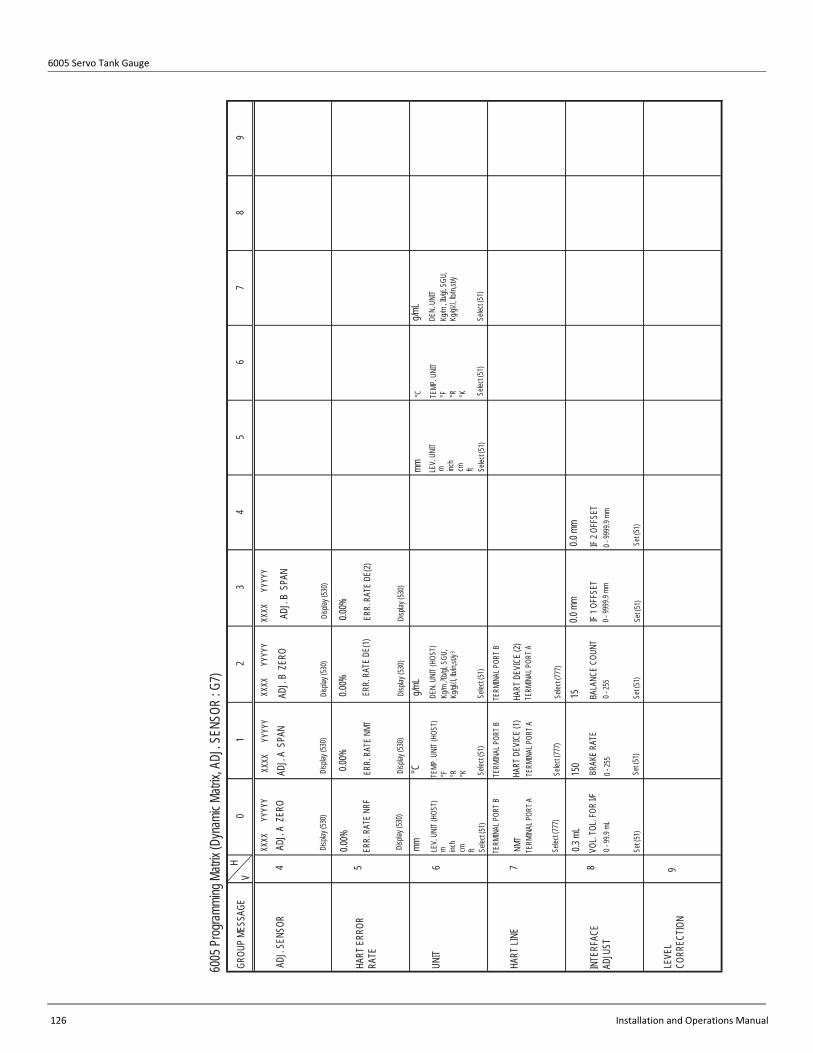
6005 Servo Tank Gauge
126 Installation and Operations Manual
01
23
45
67
89
4 5 6 7 8
VH
GROU
P ME
SSAG
E
ADJ.
SENS
OR
HART
ERR
OR
RATE
UNIT
HART
LINE
INTE
RFAC
E AD
JUST
TERM
INAL
POR
T B
NMT
TERM
INAL
POR
T A
Selec
t (777
)
TERM
INAL
POR
T BTE
RMIN
AL P
ORT B
HART
DEV
ICE
(1)TE
RMIN
AL P
ORT A
HART
DEV
ICE
(2)TE
RMIN
AL P
ORT A
0.3 m
L15
0
Selec
t (777
)Se
lect (7
77)
15VO
L. TO
L. FO
R I/F
0 - 99
.9 mL
Set (5
1)
BRAK
E RA
TE0 -
255
0 - 25
5
Set (5
1)Se
t (51)
BALA
NCE
COUN
T
0.0 m
m
IF 1 O
FFSE
T 0
- 999
9.9 m
m
Set (5
1)
0.0 m
m
Set (5
1)
IF 2 O
FFSE
T 0
- 999
9.9 m
m
6005
Prog
rammi
ng M
atrix
(Dyn
amic
Matrix
, ADJ
. SEN
SOR
: G7)
mm LEV.
UNI
T (HO
ST)
m inch
cm ft Selec
t (51)
°C TEMP
. UNI
T (HO
ST)
°F °R °K Selec
t (51)
g/mL
DEN.
UNI
T (HO
ST)
Kg/m
, Ib/g
l, SGU
, Kg
/gl/.l,
lb/in
,st/y
3
3
Selec
t (51)
mm LEV.
UNI
Tm inc
hcm ft Se
lect (5
1)
°C TEMP
. UNI
T°F °R °K Se
lect (5
1)
g/mL
DEN.
UNI
T Kg
/m , I
b/gl, S
GU,
Kg/gl
/.l, lb
/in,st
/y
Selec
t (51)
9LE
VEL
CORR
ECTIO
N
ADJ
. A Z
ERO
Disp
lay (5
30)
ADJ
. A S
PAN
Disp
lay (5
30)
ADJ
. B Z
ERO
ADJ
. B S
PAN
Disp
lay (5
30)
Disp
lay (5
30)
0.00%
XXXX
Y
YYYY
XXXX
Y
YYYY
XXXX
Y
YYYY
XXXX
Y
YYYY
ERR.
RAT
E NR
F
Disp
lay (5
30)
0.00%
ERR.
RAT
E NM
T
Disp
lay (5
30)
0.00%
ERR.
RAT
E DE
(1)
Disp
lay (5
30)
0.00%
ERR.
RAT
E DE
(2)
Disp
lay (5
30)
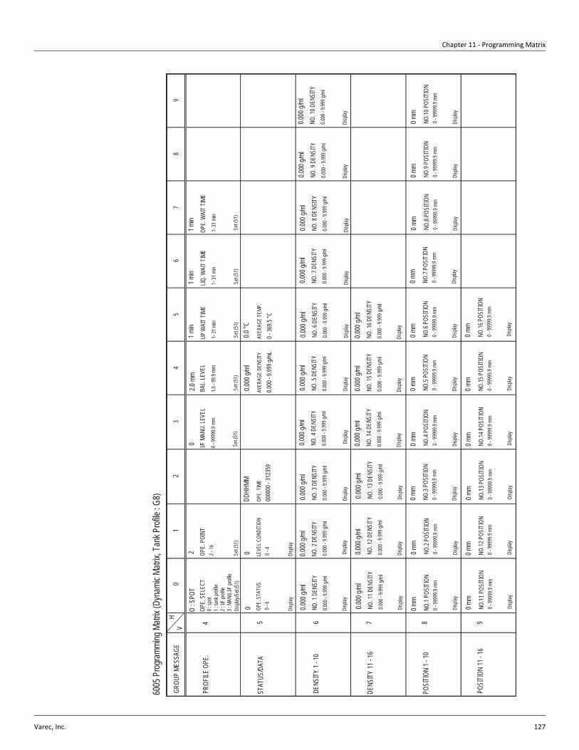
Chapter 11 - Programming Matrix
Varec, Inc. 127
01
23
45
67
89
4 5 6 7 8 9
VH
6005
Prog
rammi
ng M
atrix
(Dyn
amic
Matrix
, Tan
k Prof
ile : G
8)
GROU
P ME
SSAG
E
PROF
ILE O
PE.
STAT
US/D
ATA
DENS
ITY 1
- 10
DENS
ITY 11
- 16
POSI
TION
1 - 10
POSI
TION
11 - 1
6
O : S
POT
OPE.
SEL
ECT
0 : sp
ot1 :
tank
profi
le2 :
I/F pr
ofile
3 : M
ANU.
I/F pr
ofile
Disp
lay/S
et (51
)
2 OPE.
POI
NT2 -
16
0 I/F M
ANU.
LEVE
L0 -
9999
9.9 m
m
2.0 m
mBA
L. LE
VEL
1.0 - 9
9.9 m
m
1 min
UP W
AIT T
IME
1- 31
min
1 min
LIQ. W
AIT T
IME
1- 31
min
1 min
OPE.
WAI
T TIM
E1-
31 m
in
0 OPE.
STA
TUS
0 - 6
0 LEVE
L CON
DITIO
N0 -
4
Disp
lay
Set (5
1)Se
t (51)
Set (5
1)Se
t (51)
Set (5
1)Se
t (51)
Disp
lay
DDHH
MMOP
E. TI
ME00
0000
- 312
359
0.000
g/ml
AVER
AGE
DENS
ITY
0.000
- 9.99
9 g/m
L
0.0 °C
AVER
AGE
TEMP
.
0 - 36
9.5 °C
0.000
g/ml
NO. 1
DEN
SITY
0.000
- 9.99
9 g/m
l
0.000
g/ml
NO. 2
DEN
SITY
0.000
- 9.99
9 g/m
l
0.000
g/ml
NO. 3
DEN
SITY
0.000
- 9.99
9 g/m
l
0.000
g/ml
NO. 4
DEN
SITY
0.000
- 9.99
9 g/m
l
0.000
g/ml
NO. 5
DEN
SITY
0.000
- 9.99
9 g/m
l
0.000
g/ml
NO. 6
DEN
SITY
0.000
- 9.99
9 g/m
l
0.000
g/ml
NO. 7
DEN
SITY
0.000
- 9.99
9 g/m
l
0.000
g/ml
NO. 8
DEN
SITY
0.000
- 9.99
9 g/m
l
0.000
g/ml
NO. 9
DEN
SITY
0.000
- 9.99
9 g/m
l
0.000
g/ml
NO. 1
0 DEN
SITY
0.000
- 9.99
9 g/m
l
Disp
layDi
splay
Disp
layDi
splay
Disp
layDi
splay
Disp
layDi
splay
Disp
layDi
splay
0.000
g/ml
NO. 1
1 DEN
SITY
0.000
- 9.99
9 g/m
l
Disp
lay
0.000
g/ml
NO. 1
2 DEN
SITY
0.000
- 9.99
9 g/m
l
Disp
lay
0.000
g/ml
NO. 1
3 DEN
SITY
0.000
- 9.99
9 g/m
l
Disp
lay
0.000
g/ml
NO. 1
4 DEN
SITY
0.000
- 9.99
9 g/m
l
Disp
lay
0.000
g/ml
NO. 1
5 DEN
SITY
0.000
- 9.99
9 g/m
l
Disp
lay
0.000
g/ml
NO. 1
6 DEN
SITY
0.000
- 9.99
9 g/m
l
Disp
lay
0 mm
NO.1
POSI
TION
0 - 99
999.9
mm
0 mm
NO.2
POSI
TION
0 - 99
999.9
mm
Disp
layDi
splay
0 mm
NO.3
POSI
TION
0 - 99
999.9
mm
Disp
lay
0 mm
NO.4
POSI
TION
0 - 99
999.9
mm
Disp
lay
0 mm
NO.5
POSI
TION
0 - 99
999.9
mm
Disp
lay
0 mm
NO.6
POSI
TION
0 - 99
999.9
mm
Disp
lay
0 mm
NO.7
POSI
TION
0 - 99
999.9
mm
Disp
lay
0 mm
NO.8
POSI
TION
0 - 99
999.9
mm
Disp
lay
0 mm
NO.9
POSI
TION
0 - 99
999.9
mm
Disp
lay
0 mm
NO.10
POS
ITION
0 - 99
999.9
mm
Disp
lay
0 mm
NO.11
POS
ITION
0 - 99
999.9
mm
Disp
lay
0 mm
NO.12
POS
ITION
0 - 99
999.9
mm
Disp
lay
0 mm
NO.13
POS
ITION
0 - 99
999.9
mm
Disp
lay
0 mm
NO.14
POS
ITION
0 - 99
999.9
mm
Disp
lay
0 mm
NO.15
POS
ITION
0 - 99
999.9
mm
Disp
lay
0 mm
NO.16
POS
ITION
0 - 99
999.9
mm
Disp
lay

6005 Servo Tank Gauge
128 Installation and Operations Manual
01
23
45
67
89
4 5 6 7 8 9
VH
6005
Pro
gram
ming
Matr
ix (D
ynam
ic Ma
trix, In
terfac
e Pro
file : G
9)
GROU
P ME
SSAG
E
STAT
US/D
ATA
DENS
ITY
1 - 10
DENS
ITY
11 -
16
POSI
TION
1 - 1
0
POSI
TION
11- 1
6
0 OPE.
STA
TUS
0 - 6
0 LEVE
L CON
DITI
ON0 -
4
Disp
layDi
splay
DDHH
MMOP
E. T
IME
0000
00 -
3123
59
0.000
g/ml
AVER
AGE
DENS
ITY
0.000
- 9.9
99 g/
ml
0.0 °C
AVER
AGE
TEMP
.
0 - 36
9.5 °C
0.000
g/ml
NO. 1
DEN
SITY
0.000
- 9.9
99 g/
ml
0.000
g/ml
NO. 2
DEN
SITY
0.000
- 9.9
99 g/
ml
0.000
g/ml
NO. 3
DEN
SITY
0.000
- 9.9
99 g/
ml
0.000
g/ml
NO. 4
DEN
SITY
0.000
- 9.9
99 g/
ml
0.000
g/ml
NO. 5
DEN
SITY
0.000
- 9.9
99 g/
ml
0.000
g/ml
NO. 6
DEN
SITY
0.000
- 9.9
99 g/
ml
0.000
g/ml
NO. 7
DEN
SITY
0.000
- 9.9
99 g/
ml
0.000
g/ml
NO. 8
DEN
SITY
0.000
- 9.9
99 g/
ml
0.000
g/ml
NO. 9
DEN
SITY
0.000
- 9.9
99 g/
ml
0.000
g/ml
NO. 1
0 DEN
SITY
0.000
- 9.9
99 g/
ml
Disp
layDi
splay
Disp
layDi
splay
Disp
layDi
splay
Disp
layDi
splay
Disp
layDi
splay
0.000
g/ml
NO. 1
1 DEN
SITY
0.000
- 9.9
99 g/
ml
Disp
lay
0.000
g/ml
NO. 1
2 DEN
SITY
0.000
- 9.9
99 g/
ml
Disp
lay
0.000
g/ml
NO. 1
3 DEN
SITY
0.000
- 9.9
99 g/
ml
Disp
lay
0.000
g/ml
NO. 1
4 DEN
SITY
0.000
- 9.9
99 g/
ml
Disp
lay
0.000
g/ml
NO. 1
5 DEN
SITY
0.000
- 9.9
99 g/
ml
Disp
lay
0.000
g/ml
NO. 1
6 DEN
SITY
0.000
- 9.9
99 g/
ml
Disp
lay
0 mm
NO.1
POSI
TION
0 - 99
999.9
mm
0 mm
NO.2
POSI
TION
0 - 99
999.9
mm
Disp
layDi
splay
0 mm
NO.3
POSI
TION
0 - 99
999.9
mm
Disp
lay
0 mm
NO.4
POSI
TION
0 - 99
999.9
mm
Disp
lay
0 mm
NO.5
POSI
TION
0 - 99
999.9
mm
Disp
lay
0 mm
NO.6
POSI
TION
0 - 99
999.9
mm
Disp
lay
0 mm
NO.7
POSI
TION
0 - 99
999.9
mm
Disp
lay
0 mm
NO.8
POSI
TION
0 - 99
999.9
mm
Disp
lay
0 mm
NO.9
POSI
TION
0 - 99
999.9
mm
Disp
lay
0 mm
NO.10
POS
ITIO
N0 -
9999
9.9 m
m
Disp
lay
0 mm
NO.11
POS
ITIO
N0 -
9999
9.9 m
m
Disp
lay
0 mm
NO.12
POS
ITIO
N0 -
9999
9.9 m
m
Disp
lay
0 mm
NO.13
POS
ITIO
N0 -
9999
9.9 m
m
Disp
lay
0 mm
NO.14
POS
ITIO
N0 -
9999
9.9 m
m
Disp
lay
0 mm
NO.15
POS
ITIO
N0 -
9999
9.9 m
m
Disp
lay
0 mm
NO.16
POS
ITIO
N0 -
9999
9.9 m
m
Disp
lay
0 mm
I/F LE
VEL
0 - 99
999.9
mm
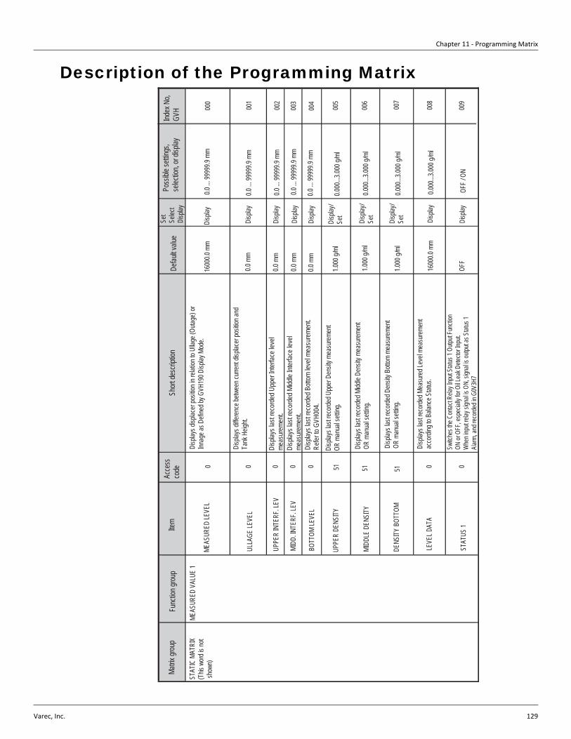
Chapter 11 - Programming Matrix
Varec, Inc. 129
Description of the Programming Matrix
0 0 0 0 0 51 0 0
Matrix
grou
pFu
nctio
n grou
pIte
mAc
cess
co
de
STAT
IC M
ATRI
X(T
his w
ord is
not
show
n)
MEAS
URED
VAL
UE 1
MEAS
URED
LEVE
L
ULLA
GE LE
VEL
UPPE
R IN
TERF
. LEV
MIDD
. INTE
RF. L
EV
BOTT
OM LE
VEL
UPPE
R DE
NSITY
MIDD
LE D
ENSI
TY
DENS
ITY B
OTTO
M
LEVE
L DAT
A
STAT
US 1
Short
desc
riptio
nDe
fault v
alue
Set
Selec
tDi
splay
Poss
ible s
etting
s, se
lectio
n, or
displa
yInd
ex N
o, GV
H
Disp
lays d
isplac
er po
sition
in re
lation
to U
llage
(Outa
ge) o
rInn
age a
s Defi
ned b
y GVH
190 D
isplay
Mod
e.16
000.0
mm
Disp
lay0.0
... 99
999.9
mm
000
Disp
lays d
ifferen
ce be
twee
n curr
ent d
isplac
er po
sition
and
Tank
Heig
ht.
Disp
lays l
ast r
ecor
ded M
iddle
Inter
face l
evel
meas
urem
ent.
Disp
lays l
ast r
ecor
ded U
pper
Inter
face l
evel
meas
urem
ent.
Disp
lays l
ast r
ecor
ded B
ottom
leve
l mea
sure
ment.
Refer
to G
VH00
4.Di
splay
s las
t reco
rded U
pper
Dens
ity m
easu
remen
t OR
man
ual s
etting
.
Disp
lays l
ast re
corde
d Midd
le De
nsity
mea
surem
ent
OR m
anua
l sett
ing.
51 51Di
splay
s las
t reco
rded D
ensit
y Bott
om m
easu
remen
t OR
man
ual s
etting
.
Disp
lays l
ast re
corde
d Mea
sured
Leve
l mea
surem
ent
acco
rding
to B
alanc
e Stat
us.
Switc
hes t
he C
ontac
t Rela
y Inp
ut St
atus 1
Outp
ut Fu
nctio
n ON
or O
FF, e
spec
ially
for O
il Lea
k Dete
ctor In
put.
Whe
n inp
ut rel
ay si
gnal
is ON
, sign
al is
outpu
t as S
tatus
1 Ala
rm, a
nd re
corde
d in G
0V3H
7
0.0 m
mDi
splay
0.0 ...
9999
9.9 m
m00
1
002
003
004
005
006
007
008
009
OFF /
ON
Disp
layOF
F
1600
0.0 m
mDi
splay
0.000
...3.00
0 g/m
l
0.000
...3.00
0 g/m
l
0.000
...3.00
0 g/m
l
0.000
...3.00
0 g/m
l
0.0 ...
9999
9.9 m
m
0.0 ...
9999
9.9 m
m
0.0 ...
9999
9.9 m
m
Disp
lay
Disp
lay
Disp
lay
Disp
lay/
Set
Disp
lay/
Set
Disp
lay/
Set
1.000
g/ml
1.000
g/ml
1.000
g/ml
0.0 m
m
0.0 m
m
0.0 m
m

6005 Servo Tank Gauge
130 Installation and Operations Manual
0 0 0 0 0 0
Matrix
grou
pFu
nctio
n grou
pIte
mAc
cess
co
deSh
ort de
scrip
tion
Defau
lt valu
eSe
tSe
lect
Disp
lay
Poss
ible s
etting
s, se
lectio
n, or
displa
yInd
ex N
o, GV
H
STAT
IC M
ATRI
X(T
his w
ord is
not
show
n)
MEAS
URED
VAL
UE 2
LIQUI
D TE
MP.
DEV(
1)
DEV(
2)
GAS
TEMP
ERAT
URE
ZERO
POI
NT
SPAN
LENG
TH U
NIT
Disp
lays L
iquid
Temp
eratur
e data
refle
cted f
rom G
4V4H
0 (NM
T)or
from
G5V4
H0 (H
ART D
ev 1)
if G5V
4H9 =
"Liqu
id Te
mpera
ture"
Disp
lays P
rimary
Vari
able
data
reflec
ted fro
m G5
V4H0
(HAR
T Dev
1) w
hen G
5V4H
0 = O
N,
Liquid
Temp
eratur
e or G
as Te
mpera
ture.
Liquid
Temp
eratur
e data
is als
o cop
ied to
G0V
1H0.
Gas T
emep
eratur
e data
is al
so co
pied
G0V1
H0 un
less G
6V4H
9 = G
as te
mpera
ture
Disp
lays P
rimary
Vari
able
data
reflec
ted fro
m G6
V4H0
(HAR
T Dev
2)wh
en G
6V4H
9 = O
N or
Gas T
empe
rature
. Ga
s tem
perat
ure da
ta is
also c
opied
to G
0V1H
3Di
splay
s Gas
Temp
eratur
e data
refle
cted f
rom G
4V4H
1, or
from
G5V4
H0 if
G5V4
H9= G
as Te
mepe
rature
, or fr
om
G6V4
H0 if
G6V4
H9 =
Gas T
empe
rature
WAT
ER B
OTTO
M 0
Disp
lays w
ater in
terfac
e lev
el da
ta rec
eived
from
NMT 5
39 P
rothe
rmo W
B de
vice.
0.0 m
mDi
splay
Disp
lays Z
ero P
oint fo
r Com
muwi
n II b
ar gra
ph
Disp
lays S
pan f
or Co
mmuw
in II b
ar gra
ph
Disp
lays u
nit of
leng
th (se
lected
at G
7V6H
0) for
Co
mmuw
in II b
ar gra
ph
0.0 °C
0.0 °C
0 mm
1600
0.0 m
m
Disp
lay
Disp
lay
Disp
lay
Disp
lay
Disp
lay
Disp
lay
Disp
lay-49
.9 ...
249.9
°C
0.0 ...
9999
9.9 m
m
0.0 ...
9999
9.9 m
m
-49.9
... 24
9.9 °C
0.0 ...
9999
9.9 m
m
0.0 ...
9999
9.9 m
m
mm01
9
018
017
014
013
012
011
010
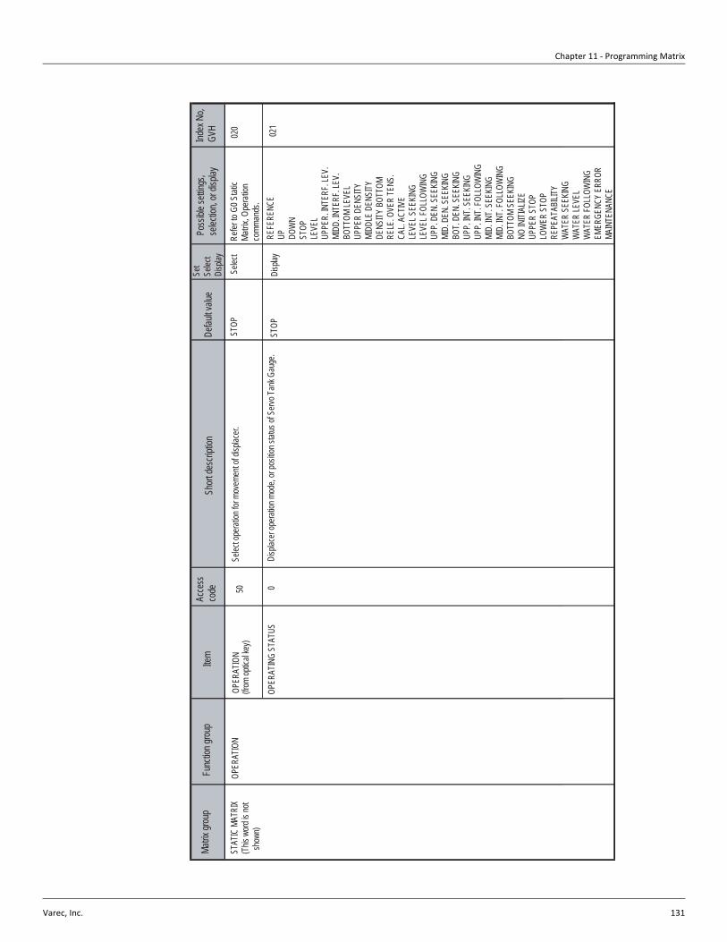
Chapter 11 - Programming Matrix
Varec, Inc. 131
0
Matrix
grou
pFu
nctio
n grou
pIte
mAc
cess
co
deSh
ort de
scrip
tion
Defau
lt valu
eSe
tSe
lect
Disp
lay
Poss
ible s
etting
s, se
lectio
n, or
displa
yInd
ex N
o, GV
H
STAT
IC M
ATRI
X(T
his w
ord is
not
sho
wn)
OPER
ATIN
G ST
ATUS
Disp
lacer
opera
tion m
ode,
or po
sition
statu
s of S
ervo T
ank G
auge
. ST
OPDi
splay
021
REFE
RENC
EUP DO
WN
STOP
LEVE
LUP
PER.
INTE
RF. L
EV.
MIDD
. INTE
RF. L
EV.
BOTT
OM LE
VEL
UPPE
R DE
NSITY
MIDD
LE D
ENSI
TYDE
NSITY
BOT
TOM
RELE
. OVE
R TE
NS.
CAL.
ACTIV
ELE
VEL S
EEKI
NGLE
VEL F
OLLO
WIN
GUP
P. D
EN. S
EEKI
NGMI
D. D
EN. S
EEKI
NGBO
T. DE
N. S
EEKI
NGUP
P. IN
T. SE
EKIN
GUP
P. IN
T. FO
LLOW
ING
MID.
INT.
SEEK
ING
MID.
INT.
FOLL
OWIN
GBO
TTOM
SEE
KING
NO IN
ITIAL
IZEUP
PER
STOP
LOW
ER S
TOP
REPE
ATAB
ILITY
WAT
ER S
EEKI
NGW
ATER
LEVE
LW
ATER
FOLL
OWIN
GEM
ERGE
NCY
ERRO
RMA
INTE
NANC
E
OPER
ATIO
N(fr
om op
tical
key)
OPER
ATIO
N50
Selec
t ope
ration
for m
ovem
ent o
f disp
lacer.
Selec
tST
OP02
0Re
fer to
G0 S
tatic
Matrix
, Ope
ratio
n co
mman
ds.
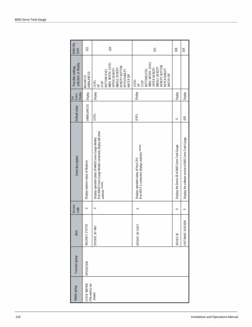
6005 Servo Tank Gauge
132 Installation and Operations Manual
0
Matrix
grou
pFu
nctio
n grou
pIte
mAc
cess
co
deSh
ort de
scrip
tion
Defau
lt valu
eSe
tSe
lect
Disp
lay
Poss
ible s
etting
s, se
lectio
n, or
displa
yInd
ex N
o, GV
H
STAT
IC M
ATRI
X(T
his w
ord is
not
sho
wn)
OPER
ATIO
NBA
LANC
E ST
ATUS
Disp
lays b
alanc
e stat
us of
disp
lacer.
UNBA
LANC
EDDi
splay
022
BALA
NCED
UNBA
LANC
ED
OPER
AT. B
Y NR
F0
Disp
lays o
perat
ion st
atus o
f N46
50 S
ervo G
uage
Mon
itor.
If no N
4650
Serv
o Gua
ge M
onito
r con
necte
d, dis
play w
ill sh
ow
aster
isks *
******
.
Disp
layLE
VEL
LEVE
LUP ST
OPBO
TTOM
LEVE
LMI
DD. IN
TERF
. LEV
ELUP
PER
DENS
ITYMI
DDLE
DEN
SITY
DENS
ITY B
OTTO
MRE
PEAT
ABILI
TYW
ATER
DIP
024
OPER
AT. B
Y HO
ST0
Disp
lays o
perat
ion st
atus o
f Hos
t CPU
.If n
o HOS
T is c
onne
cted,
displa
ys as
terisk
s ****
***.
LEVE
LDi
splay
LEVE
LUP ST
OPBO
TTOM
LEVE
LMI
DD. IN
TERF
. LEV
ELUP
PER
DENS
ITYMI
DDLE
DEN
SITY
DENS
ITY B
OTTO
MRE
PEAT
ABILI
TYW
ATER
DIP
025
DEVI
CE ID
0Di
splay
s the
Dev
ice ID
of 60
05 S
ervo T
ank G
auge
.0
Disp
lay
SOFT
WAR
E VE
RSIO
N0
Disp
lays t
he so
ftware
versi
on of
6005
Serv
o Tan
k Gau
ge.
428
Disp
lay
028
029

Chapter 11 - Programming Matrix
Varec, Inc. 133
0
Matrix
grou
pFu
nctio
n grou
pIte
mAc
cess
co
deSh
ort de
scrip
tion
Defau
lt valu
eSe
tSe
lect
Disp
lay
Poss
ible s
etting
s, se
lectio
n, or
displa
yInd
ex N
o, GV
H
STAT
IC M
ATRI
X(T
his w
ord is
not
sho
wn)
MORE
FUNC
TION
MATR
IX O
FUs
e (+)
and (
-) ke
ys to
scrol
l throu
gh 9
Dyna
mic M
atrix
Grou
p sele
ction
s. Pr
ess "
E" ke
y to s
elect
one f
or ac
cess
to
more
data.
CALIB
RATIO
NDE
VICE
DAT
ASE
RVIC
ETE
MPER
ATUR
EHA
RT D
EVIC
E (1)
HART
DEV
ICE
(2)AD
J. SE
NSOR
030
ALAR
M CO
NTAC
T0
Disp
lay al
arm m
essa
ge de
pend
ing on
curre
nt sta
tus.
Disp
lay03
4
(Cale
ndar)
0Di
splay
s date
and t
ime a
s yym
mdd _
_hh:m
m:ss
. No
t tran
sferre
d by R
ackb
us.
CALIB
RATIO
NSe
lect
Disp
layJa
pane
se lo
cal
time
e.g. 5
410 1
9:10:4
1Ye
ar Mo
nth D
ayHH
:MM:
SS
033
NO A
LARM
035
(Alar
m Hi
story)
0Us
e (+)
and (
-) ke
ys to
scrol
l throu
gh hi
story
of ala
rms.
Up to
99 al
arms r
ecord
ed, th
en ol
dest
alarm
is ov
erwritt
enby
new
data.
Disp
lay
DIAG
NOST
IC C
O0
Disp
lays c
urren
t self
-diag
nosti
c cod
e.Di
splay
NO A
LARM
NO E
RROR
036
Alarm
mes
sage
Alarm
histo
ry
Error
mes
sage
(Erro
r Hist
ory)
0Us
e (+)
and (
-) ke
ys to
scrol
l throu
gh hi
story
of err
ors, in
for
mat y
ymmd
d hhm
m°° #
#. Up
to 99
alarm
s rec
orded
, the
n olde
st ala
rm is
overw
ritten
by ne
w da
ta.
MPU:
STAR
T ACT
Disp
layEr
ror hi
story
037
RESE
T ALM
. DIA
GNO
0Re
set E
rror H
istory
by se
tting =
ON.
OFF
Disp
lay03
8
ACCE
SS C
ODE
0Se
t acc
ess c
ode t
o view
and c
hang
e to m
atrix
data.
High
er ac
cess
code
s (ex
cept
777)
give g
reater
editin
g priv
ilege
s.
0
039
Set
50: O
perat
or, 51
: tech
nician
, 77
7: req
uired
to se
lect E
Ex i H
ART l
ine
0, 50
, 51,
530,
777

6005 Servo Tank Gauge
134 Installation and Operations Manual
50
Matrix
grou
pFu
nctio
n grou
pIte
mAc
cess
co
deSh
ort de
scrip
tion
Defau
lt valu
eSe
tSe
lect
Disp
lay
Poss
ible s
etting
s, se
lectio
n, or
displa
yInd
ex N
o, GV
H
CALIB
RATIO
NLE
VEL D
ATA
TANK
HEI
GHT
Eleva
tion l
evel
of ma
nual
dippin
g refe
rence
.0 -
9999
9.9 m
m14
0
DISP
L. RA
ISE
DENS
144
1600
0.0 m
mSe
t
0 - 30
0 mm
143
150 m
mDI
SPL.
SUBM
. DEN
S
LEVE
L BEL
OW 0
149
DIP
POIN
T OFF
SET
50Di
fferen
ce be
twee
n Tan
k Heig
ht an
d Refe
rence
Pos
ition o
f Pr
oserv
o NMS
5. Th
is da
ta is
autom
atica
lly ad
justed
by
Pros
ervo s
oftwa
re wh
en S
et Le
vel p
roced
ure is
perfo
rmed
.
0.0 m
mSe
t0 -
9999
9.9 m
m14
1
DISP
LAC.
DRA
FT50
Set th
e draf
t of d
isplac
er. Th
is va
lue is
used
to ca
lculat
e G0V
0H4
Botto
m Le
vel m
easu
remen
t.10
.0 mm
Set
0 - 99
9.9 m
m
142
Diam
eter
Spec
ificati
on
Draft
30 m
m40
mm
50 m
m50
mm
70 m
m11
0 mm
110 m
m
Spec
ialSp
ecial
Std
Conic
alNM
iPT
B,
Leve
lPT
B,I/F
Varie
sVa
ries
45 m
m35
mm
14 m
m8 m
m13
mm
Typic
al Di
splac
er Dr
aft se
ttings
Set d
istan
ce fo
r disp
lacer
to ris
e abo
ve le
vel p
ositio
n duri
ng
Dens
ity op
eratio
ns.
Obse
rve th
e rule
: G1V
4H3+
G1V
4H4 =
300 n
, whe
re = i
ntege
r51
Set d
istan
ce fo
r disp
lacer
to sin
k belo
w lev
el po
sition
durin
g De
nsity
opera
tions
. Ob
serve
the r
ule: G
1V4H
3+ G
1V4H
4 = 30
0 n, w
here
= inte
ger
51
Selec
t meth
od fo
r han
dling
nega
tive l
evel
data
in V1
proto
col
comm
unica
tion.
Selec
t "99
999 m
m" to
disp
lay ne
gativ
e lev
el da
taba
ckwa
rds fro
m 99
999 m
m. S
elect
"0 m
m" to
disp
lay al
l neg
ative
level
data
as 0
mm.
150 m
m
9999
9 mm
0 - 15
00 m
m
0 - 99
999
mmSe
lect
SetSet
51
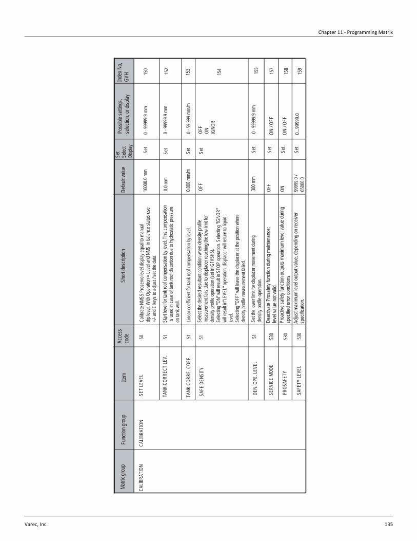
Chapter 11 - Programming Matrix
Varec, Inc. 135
Matrix
grou
pFu
nctio
n grou
pIte
mAc
cess
co
deSh
ort de
scrip
tion
Defau
lt valu
eSe
tSe
lect
Disp
lay
Poss
ible s
etting
s, se
lectio
n, or
displa
yInd
ex N
o, GV
H
CALIB
RATIO
NCA
LIBRA
TION
51
154
5115
3
50Ca
librat
e NMS
5 Pros
ervo l
evel
displa
y equ
al to
manu
al dip
leve
l. With
Ope
ration
= Le
vel a
nd N
MS in
balan
ce st
atus u
se
+/- an
d E ke
ys to
adjus
t / se
t the d
ata.
1600
0.0 m
mSe
t0 -
9999
9.9 m
m15
0
0.000
mm/
mSe
t0 -
59.99
9 mm/
m
Set
SET L
EVEL
TANK
COR
RECT
LEV.
51St
art le
vel fo
r tank
roof
comp
ensa
tion b
y lev
el. Th
is co
mpen
satio
n is
used
in ca
se of
tank
roof
distor
tion d
ue to
hydro
static
pres
sure
on ta
nk w
all.
0.0 m
mSe
t0 -
9999
9.9 m
m15
2
TANK
COR
RE. C
OEF.
Linea
r coe
fficien
t for ta
nk ro
of co
mpen
satio
n by l
evel.
SAFE
DEN
SITY
Selec
t the d
esire
d res
ultan
t con
dition
whe
n den
sity p
rofile
me
asure
ment
fails
due t
o disp
lacer
reach
ing th
e low
-limit f
or de
nsity
profi
le op
eratio
n (se
t in G
1V5H
5).
Selec
ting "
ON" w
ill res
ult in
STO
P op
eratio
n. Se
lectin
g "IG
NOR"
wi
ll res
ult in
"LEV
EL" o
perat
ion, d
isplac
er wi
ll retu
rn to
liquid
lev
el.Se
lectin
g "OF
F" w
ill lea
ve th
e disp
lacer
at the
posit
ion w
here
dens
ity pr
ofile
meas
ureme
nt fai
led.
OFF
OFF
ON IGNO
R
DEN.
OPE
. LEV
EL51
Set th
e low
er lim
it for
displa
cer m
ovem
ent d
uring
de
nsity
profi
le op
eratio
n.30
0 mm
Set
0 - 99
999.9
mm
155
SERV
ICE
MODE
PROS
AFET
Y
SAFE
TY LE
VEL
530
530
530
Deac
tivate
Pro
safet
y fun
ction
durin
g main
tenan
ce;
level
value
not v
alid.
Proa
ctive
safet
y fun
ction
outpu
ts ma
ximum
leve
l valu
e dur
ing
spec
ified e
rror c
ondit
ions
Adjus
t max
imum
leve
l outp
ut va
lue, d
epen
ding o
n rec
eiver
sp
ecific
ation
.
OFF
ON 9999
9.0 /
6500
0.0
Set
Set
Set
ON / O
FF
ON / O
FF
0...99
999.0
157
158
159

6005 Servo Tank Gauge
136 Installation and Operations Manual
50
Matrix
grou
pFu
nctio
n grou
pIte
mAc
cess
co
deSh
ort de
scrip
tion
Defau
lt valu
eSe
tSe
lect
Disp
lay
Poss
ible s
etting
s, se
lectio
n, or
displa
yInd
ex N
o, GV
H
CALIB
RATIO
NUP
PER
STOP
Set u
pper
limit o
f disp
lacer
move
ment
durin
g norm
al op
eratio
n.0 -
9999
9.9 m
m16
0
5116
4
51
1600
0 mm
Set
163
500 m
mSe
t0 -
9999
9.9 m
m
162
50 g
Set
Set
ADJU
STME
NT
LOW
ER S
TOP
350 g
Set
0 - 99
9 g
UNDE
R TE
NS. S
ET
SLOW
HOI
ST60
mm
51
10 s
Set
10 - 9
99 se
c.
167
Set lo
wer li
mit o
f disp
lacer
move
ment
durin
g norm
al op
eratio
n.16
1
OVER
TENS
. SET
51Se
t this
value
such
that
if G3V
7H0 M
easu
red W
eight
of dis
place
req
uals
or ex
ceed
s sett
ing at
G1V
6H2,
motor
will
freez
e.Inc
rease
this
param
eter if
nece
ssary
in hi
gh vi
scos
ity liq
uids.
Cauti
on!: M
agne
tic co
uplin
g disc
onne
cts ab
ove 8
00 gr
ams t
ensio
n.
Set th
is va
lue su
ch th
at if G
3V7H
0 Mea
sured
Weig
ht of
displa
cer
equa
ls or
is les
s tha
n sett
ing at
G1V
6H3,
motor
will
freez
e.De
creas
e this
param
eter if
nece
ssary
in hi
gh vi
scos
ity liq
uids.
0 - 99
9 g
Disp
lacer
will e
nter s
low sp
eed h
oist a
ccord
ing to
this
value
, us
eful if
disp
lacer
conta
cts w
ith na
rrow
valve
s.60
- 180
0 mm
DISP
L. RA
IS. R
EP.
Set th
e dist
ance
to ra
ise di
splac
er ab
ove l
iquid
surfa
ce du
ring
repea
tabilit
y tes
t.10
mm
Set
10 - 9
9 mm
165
DISP
L. W
AIT R
EP.
51Se
t the w
aiting
time a
fter d
isplac
er ris
es ab
ove l
iquid
surfa
ce
durin
g rep
eatab
ility t
est.
DISP
L. W
AIT D
IP.
51Us
ed fo
r Wate
r Lev
el co
mman
d. Se
t the w
aiting
time b
etwee
n dis
place
r bala
nce s
tatus
and r
eturn
to Le
vel.
10 s
Set
10 - 9
99 se
c.
166
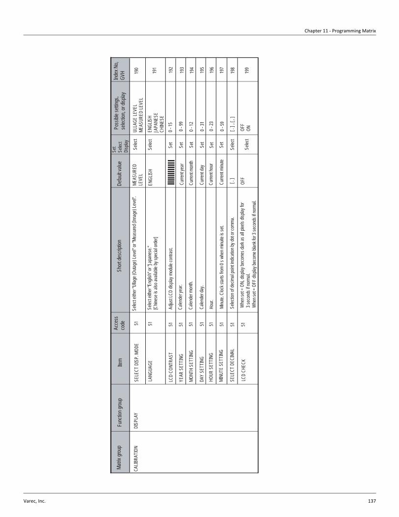
Chapter 11 - Programming Matrix
Varec, Inc. 137
Matrix
grou
pFu
nctio
n grou
pIte
mAc
cess
co
deSh
ort de
scrip
tion
Defau
lt valu
eSe
tSe
lect
Disp
lay
Poss
ible s
etting
s, se
lectio
n, or
displa
yInd
ex N
o, GV
H
DISP
LAY
SELE
CT D
ISP.
MOD
ESe
lect e
ither
"Ulla
ge (O
utage
) Lev
el" or
"Mea
sured
(Inna
ge) L
evel"
. 19
0
51
Selec
t
192
191
Set
Set
Selec
tEN
GLIS
HJA
PANE
SECH
INES
E
LCD
CONT
RAST
ENGL
ISH
51
0 - 15
Set
51ME
ASUR
ED
LEVE
LUL
LAGE
LEVE
LME
ASUR
ED LE
VEL
51
YEAR
SET
TING
Set
51
193
194
51Cu
rrent
day
0 - 31
CALIB
RATIO
N
LANG
UAGE
Selec
t eith
er "E
nglis
h" or
"Jap
anes
e."[C
hines
e is a
lso av
ailab
le by
spec
ial or
der]
Adjus
t LCD
disp
lay m
odule
contr
ast.
Calen
der y
ear.
MONT
H SE
TTIN
GCa
lende
r mon
th.
Curre
nt ye
ar0 -
99
0 - 12
DAY
SETT
ING
Calen
der d
ay.
195
Curre
nt mo
nth
HOUR
SET
TING
MINU
TE S
ETTIN
G
51 51
Hour.
Minu
te. C
lock s
tarts
from
0 s w
hen m
inuite
is se
t.
Curre
nt ho
ur
Curre
nt mi
nute
Set
Set
0 - 23
0 - 59
196
197
SELE
CT D
ECIM
AL51
Selec
tion o
f dec
imal
point
indic
ation
by do
t or c
omma
.
LCD
CHEC
K51
Whe
n set
= ON,
disp
lay be
come
s dark
as al
l pixe
ls dis
play f
or 3 s
econ
ds if
norm
al.
Whe
n set
= OFF
disp
lay be
come
blan
k for
3 sec
onds
if no
rmal.
[ . ]
Selec
t
Selec
t
[ . ] ,
[ , ]
198
OFF
OFF
ON19
9
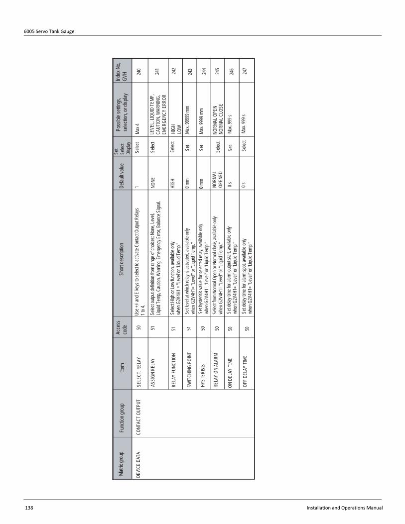
6005 Servo Tank Gauge
138 Installation and Operations Manual
Matrix
grou
pFu
nctio
n grou
pIte
mAc
cess
co
deSh
ort de
scrip
tion
Defau
lt valu
eSe
tSe
lect
Disp
lay
Poss
ible s
etting
s, se
lectio
n, or
displa
yInd
ex N
o, GV
H
CONT
ACT O
UTPU
TSE
LECT
. REL
AYUs
e +/- a
nd E
keys
to se
lect to
activ
ate C
ontac
t Outp
ut Re
lays
1 to 4
.24
0Se
lect
242
241
Selec
tLE
VEL,
LIQUI
D TE
MP,
CAUT
ION,
WAR
NING
,EM
ERGE
NCY
ERRO
R
RELA
Y FU
NCTIO
N
NONE
51
HIGH
LOW
501
Max 4
51
Set
5124
3
50
DEVI
CE D
ATA
ASSI
GN R
ELAY
Selec
t outp
ut de
finitio
n from
rang
e of c
hoice
s; No
ne, L
evel,
Liquid
Temp
, Cau
tion,
Warn
ing, E
merge
ncy E
rror, B
alanc
e Sign
al.
Selec
t High
or Lo
w fun
ction
, ava
ilable
only
when
G2V
4H1 =
"Lev
el"or
"Liqu
id Te
mp."
SWITC
HING
POI
NT
HYST
ERIS
ISSe
t hys
terisi
s valu
e for
selec
ted re
lay, a
vaila
ble on
ly wh
en G
2V4H
1= "L
evel"
or "L
iquid
Temp
." 24
4
0 mm
RELA
Y ON
ALA
RM50
Selec
t from
Norm
al Op
en or
Norm
al clo
se, a
vaila
ble on
lywh
en G
2V4H
1= "L
evel"
or "L
iquid
Temp
." NO
RMAL
OP
ENED
Set
50 50
Set
Selec
t
HIGH
Selec
t
Set le
vel a
t whic
h rela
y is a
ctiva
ted, a
vaila
ble on
ly wh
en G
2V4H
1= "L
evel"
or "L
iquid
Temp
."Ma
x. 99
999 m
m
ON D
ELAY
TIME
Set d
elay t
ime f
or ala
rm ou
tput s
tart, a
vaila
ble on
ly wh
en G
2V4H
1= "L
evel"
or "L
iquid
Temp
."
OFF D
ELAY
TIME
Set d
elay t
ime f
or ala
rm sp
ot, av
ailab
le on
ly wh
en G
2V4H
1= "L
evel"
or "L
iquid
Temp
."
0 mm
NORM
AL O
PEN
NORM
AL C
LOSE
Max.
9999
mm
Selec
t24
5
0 sMa
x. 99
9 s24
6
0 sMa
x. 99
9 s24
7

Chapter 11 - Programming Matrix
Varec, Inc. 139
Matrix
grou
pFu
nctio
n grou
pIte
mAc
cess
co
deSh
ort de
scrip
tion
Defau
lt valu
eSe
tSe
lect
Disp
lay
Poss
ible s
etting
s, se
lectio
n, or
displa
yInd
ex N
o, GV
H
ANAL
OG O
UT. A
DJUS
TAS
SIGN
OUT
PUT 1
250
Selec
t
252
251
Set
ADJU
ST 20
mA
0 mm
5151 51 5125
3
51
DEVI
CE D
ATA
ADJU
ST 4m
A
ASSI
GN O
UTPU
T 2
ADJU
ST 4m
A25
4
NONE
ADJU
ST 20
mA51
Set
51Se
lect
Set
DEVI
CE A
T ALA
RM
255
OFF
256
Assig
n ana
log ou
tput fo
r cha
nnel
1.
Set le
vel o
r temp
eratur
e valu
e for
4 mA
outpu
t on c
hann
el 1.
Avail
able
only
when
G2V
5H0 =
"Lev
el" or
"Liqu
id Te
mp"
Set le
vel o
r temp
eratur
e valu
e for
20 m
A ou
tput o
n cha
nnel
1.Av
ailab
le on
ly wh
en G
2V5H
0 = "L
evel"
or "L
iquid
Temp
"
Assig
n ana
log ou
tput fo
r cha
nnel
2.
Set le
vel o
r temp
eratur
e valu
e for
4 mA
outpu
t on c
hann
el 2.
Avail
able
only
when
G2V
5H3 =
"Lev
el" or
"Liqu
id Te
mp"
Set le
vel o
r temp
eratur
e valu
e for
20 m
A ou
tput o
n cha
nnel
2.Av
ailab
le on
ly wh
en G
2V5H
3 = "L
evel"
or "L
iquid
Temp
"
Selec
t type
of ou
tput fo
r alar
m. S
elect
from
OFF,
HOLD
curre
nt ou
tput, M
axim
um va
lue or
Mini
mum
value
LEVE
LLIQ
UID
TEMP
.
FOR
LIQUI
D TE
MP. 0
.0
FOR
LIQUI
D TE
MP. 0
.0
LEVE
LLIQ
UID
TEMP
.FO
R LIQ
UID
TEMP
. 0.0
FOR
LIQUI
D TE
MP. 0
.0
HOLD
CUR
NT. O
UTMA
XMI
N
Set
Selec
t
NONE
/0°C
0 mm
/0°C
0 mm
/0°C
0 mm
/0°C
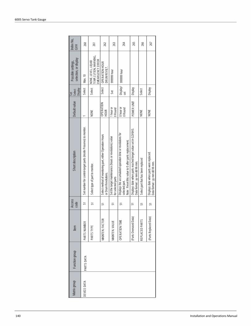
6005 Servo Tank Gauge
140 Installation and Operations Manual
Matrix
grou
pFu
nctio
n grou
pIte
mAc
cess
co
deSh
ort de
scrip
tion
Defau
lt valu
eSe
tSe
lect
Disp
lay
Poss
ible s
etting
s, se
lectio
n, or
displa
yInd
ex N
o, GV
H
PART
S DA
TAPA
RTS
NUMB
ER26
0Se
lect
262
261
NONE
, LEV
EL, L
IQUI
D TE
MP,C
UTIO
N, W
ARNI
NG,
EMEA
RGEN
CY E
RROR
MAIN
TEN.
FACT
OR
NONE
51
OPER
ATIO
N HO
URDR
UM R
EVILT
.
511
Max.
10
51 5126
3
51
DEVI
CE D
ATA
PART
S TY
PE
MAIN
TEN.
VAL
UE
OPER
ATIO
N TIM
E26
4
1 hou
r or
0 Rou
nd
(Part
s Ove
rused
Data
)51
Disp
lay/
set
51 51
Selec
t
OPER
ATIO
NHO
URSe
lect
9999
99 ho
ur
REPL
ACED
PAR
TS
(Part
s Rep
laced
Data
)
0 hou
r or
0 Rou
nd
265
NONE
266
267
Set n
umbe
r for c
ontro
l-targe
t part
s (ins
ide P
roserv
o) to
monit
or.
Selec
t type
of pa
rt to m
onito
r.
Selec
t meth
od of
mon
itorin
g part
, eith
er Op
eratio
n Hou
rs or
Drum
Rev
olutio
ns.
Set th
e targ
et ma
inten
ance
(hou
rs or
revolu
tions
) valu
e for
selec
ted pa
rtsDi
splay
s the
accu
mulat
ed op
eratio
n tim
e or r
evolu
tions
for
selec
ted pa
rt. No
te : R
eset
this v
alue t
o 0 af
ter pa
rts re
place
ment.
POW
ER U
NIT
Disp
lays d
ate w
hen p
arts r
each
ed te
rget v
alue s
et in
G2V6
H3.
Data
forma
t : yy
mm
dd hh
mm.
Selec
t part
that
has b
een r
eplac
ed
Disp
lays d
ate w
hen p
arts w
ere re
place
d.Da
ta for
mat :
yy m
m dd
hh m
m.NO
NE
Selec
t
Set
Disp
lay
Disp
lay
9999
99 ho
ur

Chapter 11 - Programming Matrix
Varec, Inc. 141
Matrix
grou
pFu
nctio
n grou
pIte
mAc
cess
co
deSh
ort de
scrip
tion
Defau
lt valu
eSe
tSe
lect
Disp
lay
Poss
ible s
etting
s, se
lectio
n, or
displa
yInd
ex N
o, GV
H
INPU
T SIG
NAL
OPE.
CON
TACT
270
Selec
t
272
271
NEW
NMS
STA
TUS
51
Disp
lays s
oftwa
re ve
rsion
of N
MS 53
x Pros
ervo.
51 51 5127
5
51
DEVI
CE D
ATA
SW V
ERSI
ON
HW V
ERSI
ON27
6
DISA
BLED
OPE.
DEN
SITY
51
Disp
aly
51
OFF
Disp
lay
OPE.
CON
T. ST
ATUS
4.xx
278
027
9
Disp
lacer
opera
tion b
y con
tact in
put. A
vaila
ble if
Conta
ct Inp
ut (I/O
3 ca
rd) fu
nctio
n is i
nstal
led. D
isplay
show
s eith
er "N
ONE"
or "A
ctiva
ted"
Disp
lays h
ardwa
re ve
rsion
of N
MS 53
x Pros
ervo.
"2.00
" = TC
B-2,
"4.00
" = TC
B - 4
, "6.0
0 = TC
B - 6
"
1.00g
/mL
Disp
lays l
iquid
dens
ity se
tting u
sed f
or co
mputi
ng bu
oyan
cy fro
ma g
iven b
alanc
e volu
me in
custo
dy tra
nsfer
mod
e.
Disp
lays t
he te
rmina
l num
bers
in us
e (bi
nary
conv
erted
to de
cimal)
CUST
ODY
TRAN
SFER
Disp
lacer
indica
tes w
hethe
r Cus
tody T
ransfe
r soft
ware
is ins
talled
and a
ctiva
ted or
not (O
FF or
ON)
. Sw
itche
s NMS
Stat
us co
des b
etwee
n old
and n
ew ve
rsion
, ne
w ve
rsion
inclu
des n
ew op
eratio
ns an
d stat
uses
.No
te : F
or Ra
ckbu
s com
munic
ation
, it is
nece
ssary
to de
fine
"Ope
rating
Stat
us"a
s On o
r OFF
.
NONE
-
Disp
aly
Set
Set
NONE
ACTIV
ATED
OFF,
ON
DISA
BLED
ENAB
LED
0 - 3.
000
2 - 25
6
Selec
t
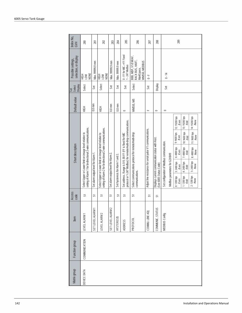
6005 Servo Tank Gauge
142 Installation and Operations Manual
Matrix
grou
pFu
nctio
n grou
pIte
mAc
cess
co
deSh
ort de
scrip
tion
Defau
lt valu
eSe
tSe
lect
Disp
lay
Poss
ible s
etting
s, se
lectio
n, or
displa
yInd
ex N
o, GV
H
COMM
UNIC
ATIO
NLE
VEL A
LARM
128
0Se
lect
282
281
5151 51
DEVI
CE D
ATA
SET L
EVEL
ALA
RM 2
284
HIGH
HYST
ERES
IS
51
0.0 m
m
286
287
SET L
EVEL
ALA
RM 1
HIGH
Set
HIGH
LOW
NONE
Max.
9999
9.9 m
mHI
GHLO
WNO
NE
0 - FF
for M
IC.->
FF Fi
xed
1 - 24
7 Mod
bus
LEVE
L ALA
RM 2
515151
WM5
50, M
/S
0
Selec
t
Set
Selec
t
283
288
289
Set
Max.
9999
9.9 m
m
BBB,
MDP
, V1/E
NRAF
,RA
CK B
US, H
ART,
MarkS
pace
,W
M550
, MOD
BUS
0 - F
0 - 14
285
Set
ADDR
ESS
PROT
OCOL
COMM
U. LI
NE A
DJ51 51
0.0 m
m
0.0 m
m
0
COMM
UNIC
. STA
TUS
MODB
US C
onfig
Selec
t Upp
er or
Lowe
r limi
t on i
nnag
e lev
el rel
ative
to
settin
g of A
larm
1 for
bi-dir
ectio
nal 2
-wire
comm
unica
tions
.
Set a
larm
outpu
t leve
l for A
larm
1.
Selec
t Upp
er or
Lowe
r limi
t on i
nnag
e lev
el rel
ative
to
settin
g of A
larm
2 for
bi-dir
ectio
nal 2
-wire
comm
unica
tions
.
Set a
larm
outpu
t leve
l for A
larm
2.
Set h
yster
esis
for A
larm
1 and
2.
Set a
ddres
s. Ra
nge i
s 0-9,
00-F
F (FF
is fix
ed fo
r MIC
pro
tocol
or 1-2
47 M
odbu
s) for
remo
te/mu
lti-dro
p com
munic
ation
s.
Selec
t com
munic
ation
s prot
ocol
for re
mote/
multi-
drop
comm
unica
tions
.
Adjus
t line
resis
tance
for s
erial
pulse
V1 c
ommu
nicati
ons.
Disp
lays c
urren
t com
munic
ation
statu
s with
Hos
t. (S
ee 60
05 S
tatus
Cod
e)
Set c
onfig
uratio
n of M
odbu
s com
munic
ation
.
Modb
us pa
ramete
rs for
G2V
8H9
0: 12
00 bp
s
/Eve
n3:
2400
bps
/E
ven
6: 48
00 bp
s
/Eve
n9:
9600
bps
/E
ven
12: 1
9200
bps
/
Even
1: 12
00 bp
s
/Odd
2: 12
00 bp
s
/Non
e
4: 24
00 bp
s
/Odd
5: 24
00 bp
s
/Non
e
7: 48
00 bp
s
/Odd
8: 48
00 bp
s
/Non
e
10: 9
600 b
ps
/Odd
11: 9
600 b
ps
/Non
e
13: 1
9200
bps
/
Odd
14: 1
9200
bps
/
None
F 0
Disp
lay
Set
Set
Max.
9999
9.9 m
m

Chapter 11 - Programming Matrix
Varec, Inc. 143
Matrix
grou
pFu
nctio
n grou
pIte
mAc
cess
co
deSh
ort de
scrip
tion
Defau
lt valu
eSe
tSe
lect
Disp
lay
Poss
ible s
etting
s, se
lectio
n, or
displa
yInd
ex N
o, GV
H
STAT
USST
ATUS
1 DE
LAY
290
Set
292
291
5151 51
DEVI
CE D
ATA
WM5
50 B
SW S
ELEC
T
WM5
50 D
ENS.
SEL
.
293
WM5
50 S
W_ID
_20x
x51
BALA
NCE
DELA
Y29
9
SELE
CT C
ONTA
CTSe
lect
0 s - 9
9 s
0 s - 9
9 s
WM5
50 A
LM. S
ELEC
T
5151
1: bit
0 Ala
rm N
o.1 (
High
-high
)
51
294
Set
Set d
elay t
ime b
etwee
n acti
vatio
n of S
tatus
1 ON
inpu
t sign
al an
d St
atus 1
outpu
t sign
al.
Selec
t norm
al rel
ay co
nditio
n for
Statu
s1: N
ormal
Open
or
Norm
al Cl
osed
.
Set th
e Alar
m Bit
for W
M550
comm
unica
tion.
(Ava
ilable
only
with
WM5
50 sp
ecific
ation
)2:
bit 1
Alarm
No.2
(Hi
gh)
3: bit
2 Ala
rm N
o.3 (
Low)
4: bit
3 Ala
rm N
o.4 (
Low-
low)
Selec
t sou
rce of
BSW
leve
l data
for W
M550
comm
unica
tion.
"0" =
Upp
er I/F
Leve
l, "1"
= (N
MT53
9)Wate
r Bott
om le
vel.
(Ava
iable
only
WM5
50 sp
ecific
ation
)
Selec
t sou
rce of
data
trans
mit in
resp
onse
to ta
sk 17
, Su
b-tas
k 11 q
uery.
(Ava
ilable
only
with
WM5
50 sp
ecific
ation
)Pa
ramete
r0:
uppe
r Den
sity
1: Pr
ofile
Ave.
Dens
.2:
IF Pr
of. A
ve. D
ens.
Dens
ity da
ta so
urce
G0V0
H5 U
pper
Dens
ity G
8V5H
4 Ave
rage D
ensit
yG9
V5H4
Ave
rage D
ensit
y
Temp
. data
sourc
eG0
V1H0
Liqu
id Te
mp.
G8V5
H5 A
verag
e Tem
p.G9
V5H5
Ave
rage T
emp.
Set th
e las
t 2 di
gits (
xx) o
f the W
M550
sens
or ad
dress
(20x
x).(A
vaila
ble on
ly wi
th W
M550
spec
ificati
on)
Sets
time b
etwee
n disp
lacer
balan
ce an
d Bala
nce S
ignal
outpu
t.
0 s NONE
1 0 0 37 0 s
NONE
NORM
AL O
PENE
DNO
RMAL
CLO
SED
(ALA
RM =
OPEN
)(A
LARM
= CL
OSED
)
1 - 3
0 - 1
0 - 2
0 - 99
295
Selec
t
Selec
t
Selec
t
Set

6005 Servo Tank Gauge
144 Installation and Operations Manual
Matrix
grou
pFu
nctio
n grou
pIte
mAc
cess
co
deSh
ort de
scrip
tion
Defau
lt valu
eSe
tSe
lect
Disp
lay
Poss
ible s
etting
s, se
lectio
n, or
displa
yInd
ex N
o, GV
H
MEAS
. WIR
E &
DRUM
WIR
E DR
UM C
IRC.
340 342
341
5151 51
SERV
ICE
DISP
LACE
R VO
LUME
VOLU
ME TO
LERA
NCE
344
WIR
E W
EIGH
TSe
t
DISP
LACE
R W
EIGH
T
515151Se
t34
3
Set Set
Set
DELA
Y
DRUM
COR
RECT
ION
DISP
L. HU
NT. C
OUNT
51
20 x
100 m
S
Set
Set
0 - 99
9.9
0 - 99
9.9
0 - 99
9.9
0 - 99
9.9
0 - 99
.9
0 - 99
9.9
Circu
mfere
nce o
f wire
drum
is m
easu
red at
facto
ry an
d ins
cribe
don
the w
ire dr
um. U
sed b
y CPU
to ca
lculat
e Mea
sured
Leve
l
Weig
ht of
meas
uring
wire
per 1
0 mete
rs. U
sed b
y CPU
to
deter
mine
balan
ce w
eight.
Stan
dard
meas
uring
wire
is
1.40 g
/10 m
. PFA
wire
is 4.
55 g/
10 m
. Has
telloy
C w
ire is
2.8 g/
10 m
Weig
ht of
displa
cer is
mea
sured
at fa
ctory
and i
nscri
bed o
n the
wire
drum
. Use
d by C
PU to
calcu
late M
easu
red an
d Inte
rface
Leve
ls an
d den
sities
.To
tal vo
lume o
f disp
lacer
is me
asure
d at fa
ctory
and i
nscri
bed o
n the
wire
drum
. Use
d by C
PU to
calcu
late I
nterfa
ce Le
vels
and
Dens
ities.
BALA
NCE
VOLU
ME51
Balan
ce vo
lume o
f disp
lacer
is me
asure
d at fa
ctory
and i
nscri
bed
on th
e wire
drum
, app
roxim
ately
one-h
alf of
Disp
lacer
Volum
e (G3
V4H3
). Use
d by C
PU to
calcu
late M
easu
red an
d Int
erfac
e Lev
els.
Disp
lacer
immu
nity t
o vari
ation
in liq
uid su
rface
leve
l duri
ng
Balan
ce co
nditio
n. Ba
sed o
n den
sity =
1.0,
settin
g for
stand
ard50
mm
displa
cer is
1.0 m
L (1 g
). Inc
rease
to co
unter
turbu
lence
and w
aves
. Lev
el ac
curac
y vari
es in
verse
ly as
Volu
me To
leran
ce.
Interv
al un
til dis
place
r res
pond
s to c
hang
e in l
iquid
level.
Incre
ase
to co
unter
small
Used
only
for S
W V
2.xx
51De
fines
the n
umbe
r of ti
mes d
isplac
er se
rches
for b
alanc
e co
nditio
n.To b
alanc
e on s
olid s
urfac
e set
= non
-zero
(e.g.
1)
300.0
0 mm
1.40 g
/10 m
255.0
g
145.0
mL
60 m
L
1.0 m
L
0.00 m
m/m
0 cou
nt
Set
Set
0 - 99
x 10
0mS
0 - 99
0 - 99
.00
345
347
348
349
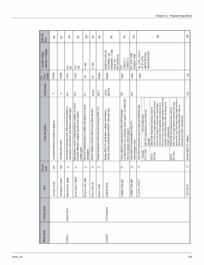
Chapter 11 - Programming Matrix
Varec, Inc. 145
Matrix
grou
pFu
nctio
n grou
pIte
mAc
cess
co
deSh
ort de
scrip
tion
Defau
lt valu
eSe
tSe
lect
Disp
lay
Poss
ible s
etting
s, se
lectio
n, or
displa
yInd
ex N
o, GV
H
SYST
EM D
ATA
SENS
OR D
ATA
360
361
51 51
SERV
ICE
CONN
ECTIO
N NR
FSe
lect
CONN
ECTIO
N NM
T
IF_LE
VEL_
SELE
CT
SOFT
RES
ET
51
Disp
lay
Selec
t
Disp
lays 6
005 S
TG sp
ecific
ation
s: so
ftware
and h
ardwa
reve
rsion
s, rem
ote co
mmun
icatio
n (ON
/OFF
), driv
e gea
r rati
o.
51
LOCA
L:MA
STER
OFF
OFF
Set
368
369
OFF
OFF,
SPOT
TEMP
.AV
ARAG
E TE
MP.
Selec
ts sw
itch f
or co
mmun
icaton
to 45
60 S
GM P
romon
itor.
For 4
560 S
GM S
W v1
.81 an
d befo
re, se
lect C
ontac
t 1. F
or 45
60 S
GMSW
v1.82
and l
ater, s
elect
Conta
ct 2.
Selec
t swi
tch fo
r com
munic
ation
to 45
3x A
TS.
Selec
t Ave
rage o
r Spo
t.Se
lect fr
ee sc
annin
g data
sourc
e for
water
leve
l (WM
550 o
nly).
Param
eter
UP_IF
_LEV
EL
WAT
ER
BOTT
OM
WAT
ER
BOTT
OM 2
Free
scan
data
sourc
eNM
S ST
G: U
pper
Interf
ace L
evel
or W
ater D
ipOp
eratio
nNM
T539
WB:
Wate
r Bott
om le
vel d
ata is
take
n for
HART
Free
Scan
. If U
pper
interf
ace c
omma
nd is
rece
ived
from
host
via S
akura
V1 c
ommu
nicati
on, W
ater B
ottom
lev
el is
return
ed. O
ther o
perat
ions r
eturn
data
base
d on
the S
ervo T
ank G
auge
settin
gs (U
pper
Interf
ace o
r Wate
r Dip
opera
tion).
Wate
r Bott
om da
ta is
taken
via i
nterru
pt-sc
anin
HART
comm
unica
tion.
NMT5
39 W
B: W
ater B
ottom
leve
l data
is ta
ken f
orHA
RT Fr
eeSc
an. U
pper
interf
ace c
omma
nd re
turns
data
base
d on t
he S
ervo T
ank G
auge
settin
gs (U
pper
Interf
ace o
r W
ater D
ip op
eratio
n). W
ater B
ottom
data
is tak
en vi
a int
errup
t-sca
n in H
ART c
ommu
nicati
on.
Resta
rts 60
05 S
TG so
ftware
.
REMO
TED
COM.
ON
SOFT
WAR
E = x
xxHA
RDW
ARE
= TCB
0xGE
AR 1:
36NO
T OVE
RSPI
LL
OFF
CONT
ACT 1
CONT
ACT 2
UP_L
EVEL
_SEL
ECT
UP_IF
_LEV
ELW
ATER
BOT
TOM
WAT
ER B
OTTO
M 2
362
Selec
t
GAUG
E DA
TA35
251
SERV
ICE
HI. A
CCUR
ACY
MODE
HI.A
CC.D
ISP.
UP35
5
GAUG
E TE
MP.
51
NON
HYST
ER. M
ODE
5151
999 °
C
Selec
t35
3
Set
Selec
t
0 - 60
0HI
. ACC
R. O
PE TI
ME51
Dista
nce d
isplac
er rai
sed i
n High
Acc
uracy
Mod
e ope
ration
.
OFF
OFF
0 s 50 m
m
Non-H
yster
isis O
perat
ion m
ode.
Whe
n turn
ed O
N dis
place
r is
raise
d ppro
x. 2m
m an
d the
n see
ks B
alanc
e con
dition
again
.
Whe
n disp
lacer
reach
es Te
mpora
ry Ba
lance
cond
ition,
it is r
aised
(G
3V5H
5) mi
llimete
rs, w
eighe
d, an
d the
n see
ks B
alanc
eco
nditio
n aga
in.
Interv
al of
Temp
orary
Balan
ce co
nditio
n unti
l disp
lacer
is rai
sed
and w
eighe
d.
Disp
lays t
empe
rature
insid
e elec
tronic
s hou
sing o
f 600
5 STG
.
Set
OFF
ON OFF
ON 0 - 30
0
356
354
Disp
lay
ACTU
AL LE
VEL
ENCO
DER
COUN
T
530
530
Leve
l from
Refe
renc
e Pos
ition t
o disp
lacer.
Enco
der p
ulse c
ount.
0 0
Disp
lay
Disp
lay35
1
350

6005 Servo Tank Gauge
146 Installation and Operations Manual
Matrix
grou
pFu
nctio
n grou
pIte
mAc
cess
co
deSh
ort de
scrip
tion
Defau
lt valu
eSe
tSe
lect
Disp
lay
Poss
ible s
etting
s, se
lectio
n, or
displa
yInd
ex N
o, GV
H
SERV
ICE
MEAS
URED
WEI
GHT
370
372
371
51 51
SERV
ICE
WEI
GHT C
ALIB
R.
RELE
. OVE
R TE
NS
DRUM
SET
TING
5137
3
Disp
layDi
splay
s ten
sion o
n mea
surin
g wire
as ca
lculat
ed by
CPU
modu
le.0.0
g
Selec
tRe
lease
disp
lacer
overt
ensio
n con
dition
.No
te : F
irst, s
et G0
V2H0
. Ope
ration
= ST
OP.
Align
s wire
drum
with
inter
nal d
etecto
r unit
. Whe
n disp
lacer
is sh
ipped
sepa
rately
, and
wire
drum
is re
move
d to i
nstal
l disp
lacer,
se
t this
functi
on pr
ior to
mak
ing ne
w W
eight
Calib
ration
. No
t requ
ired f
or All
-in-O
ne sh
ipmen
ts of
6005
STG
.Ini
tiates
Weig
ht Ta
ble re
calib
ration
proc
edure
. Ove
rwrite
s exis
ting
weigh
t table
with
new
weigh
t table
. Ca
ution
!: Onc
e rec
alibra
tion p
roced
ure be
gins i
t mus
t be
comp
leted
; i.e.
it can
not b
e stop
ped o
r rev
ersed
.
OFF
ON OFF
ON
Selec
t
Selec
t
OFF
OFF
OFF
0.0 - 9
99 g
OFF
ON
SERV
ICE
VALU
ESE
NSOR
VAL
UE38
051
Disp
lays t
he A
/D va
lues f
rom th
e enc
oder.
Sa 2
1000
:A
210
00Sb
110
00:
B
1100
0
WT.
COUN
T CAL
A
395
WT.
COUN
T CAL
. B51
394
51Di
splay
s A/D
and d
isplac
er we
ight c
orrec
tion v
alues
for S
enso
r AUs
e the
+ an
d - ke
y to s
croll t
hroug
h 50 p
oints.
Disp
lays A
/D an
d disp
lacer
weigh
t corr
ectio
n valu
es fo
r Sen
sor B
Use t
he +
and -
key t
o scro
ll thro
ugh 5
0 poin
ts.
0
0
0.0 g
0
0
0..0 g
Disp
lay
Disp
lay
SERV
ICE
DATA
~ ~ ~ ~ ~ ~ ~ ~
DISP
L. RE
FERE
NCE
ZERO
ADJ
. WEI
GHT
51 51
Leng
th for
the s
tartin
g pos
ition o
f weig
ht ca
librat
ion.
The d
isplac
er wi
ll stop
at th
is po
sition
with
out re
gard
to the
high
sto
p lev
el wh
en it
is ho
isted
, if th
e high
stop
leve
l is se
t high
er tha
nthi
s poin
t.Lo
w we
ight fo
r weig
ht ca
librat
ion.
70 m
mSe
t10
...999
mm
378
0.0 g
Set
0.0...9
99.9
g37
9
Disp
lay

Chapter 11 - Programming Matrix
Varec, Inc. 147
Matrix
grou
pFu
nctio
n grou
pIte
mAc
cess
co
deSh
ort de
scrip
tion
Defau
lt valu
eSe
tSe
lect
Disp
lay
Poss
ible s
etting
s, se
lectio
n, or
displa
yInd
ex N
o, GV
H
TEMP
ERAT
URE
DATA
LIQUD
TEMP
.44
0 443
442
5151 51
TEMP
ERAT
URE
WAT
ER B
OTTO
M
447
GAS
TEMP
ERAT
URE
51RE
FERE
NCE
150
Disp
lays c
urren
t ava
rage l
iquid
tempe
rature
.
DIAG
NOST
IC51
449
Disp
lays c
urren
t ave
rage g
as te
mpera
ture.
444
51
MEAS
URED
LEVE
L
LEV.
DAT
A SE
LECT
Disp
lays M
easu
red Le
vel d
ata re
ceive
d from
6005
STG
,de
pend
ing on
selec
tion a
t G4V
4H3 L
evel
Data
Selec
t.
Disp
lays w
ater le
vel d
ata fro
m the
NMT
539 W
ater B
ottom
. G3
V6H8
mus
t be s
et to
eithe
r "W
ATER
BOT
TOM"
or
"WAT
ER B
OTTO
M2".
xx °C
Disp
lay
Disp
lay
Disp
lay
Selec
t
Disp
lay
Disp
lay
Disp
lay
Selec
t leve
l data
to re
ceive
from
6005
STG
, use
d for
avera
ging c
alcula
tions
. Sele
ct "V
H00"
to re
ceive
Mea
sured
Leve
l (ac
tual d
isplac
er po
sition
). Se
lect "
VH08
" to r
eceiv
e Lev
el Da
ta (la
st rec
orded
leve
l pos
ition).
51
Disp
lays r
eferen
ce re
sistan
ce on
circu
it boa
rd co
rresp
ondin
g to
0°C.
Disp
lays r
eferen
ce re
sistan
ce on
circu
it boa
rd co
rresp
ondin
g to
150°
C.
zz °C
aaaa
.a mm
VH00
0.0 m
m
0.0 °C
150.0
°C
Depe
nding
on a
spec
ificati
onan
d mea
sured
value
.De
pend
ing on
a sp
ecific
ation
and m
easu
red va
lue.
Depe
nding
on a
spec
ificati
onan
d mea
sured
value
.VH
00 or
VH0
8
Depe
nding
on a
spec
ificati
onan
d mea
sured
value
.
Depe
nding
on a
spec
ificati
onan
d mea
sured
value
.De
pend
ing on
a sp
ecific
ation
and m
easu
red va
lue.
441

6005 Servo Tank Gauge
148 Installation and Operations Manual
Matrix
grou
pFu
nctio
n grou
pIte
mAc
cess
co
deSh
ort de
scrip
tion
Defau
lt valu
eSe
tSe
lect
Disp
lay
Poss
ible s
etting
s, se
lectio
n, or
displa
yInd
ex N
o, GV
H
ELEM
ENT T
EMP.
TEMP
. NO.
145
0
453
452
5151 51
TEMP
ERAT
URE
TEMP
. NO.
2
51
Disp
lays t
empe
rature
of el
emen
t 1 (lo
west
eleme
nt).
5151
aa.a
°CDi
splay
Disp
lay
Disp
lay
Disp
lay
Disp
lay
Disp
lay
51
451
TEMP
. NO.
3
TEMP
. NO.
4
TEMP
. NO.
5
TEMP
. NO.
6
TEMP
. NO.
7
TEMP
. NO.
8
TEMP
. NO.
9
TEMP
. NO.
10
Disp
lays t
empe
rature
of el
emen
t 2.
Disp
lays t
empe
rature
of el
emen
t 3.
Disp
lays t
empe
rature
of el
emen
t 4.
Disp
lays t
empe
rature
of el
emen
t 5.
Disp
lays t
empe
rature
of el
emen
t 6.
Disp
lays t
empe
rature
of el
emen
t 7.
Disp
lays t
empe
rature
of el
emen
t 8.
Disp
lays t
empe
rature
of el
emen
t 9.
Disp
lays t
empe
rature
of el
emen
t 10.
bb.b
°C
cc.c
°C
dd.d°
C
ee.e
°C
ff.f °C
gg.g
°C
hh.h
°C
ii.i °C
jj.j °C
Disp
lay
Disp
lay
Disp
lay
Disp
lay
51 51 51
454
455
456
457
458
459
Depe
nding
on a
spec
ificati
on an
d me
asure
d valu
e.
-49.9
... 24
9.9 °C
-49.9
... 24
9.9 °C
-49.9
... 24
9.9 °C
-49.9
... 24
9.9 °C
-49.9
... 24
9.9 °C
-49.9
... 24
9.9 °C
-49.9
... 24
9.9 °C
-49.9
... 24
9.9 °C
-49.9
... 24
9.9 °C
-49.9
... 24
9.9 °C
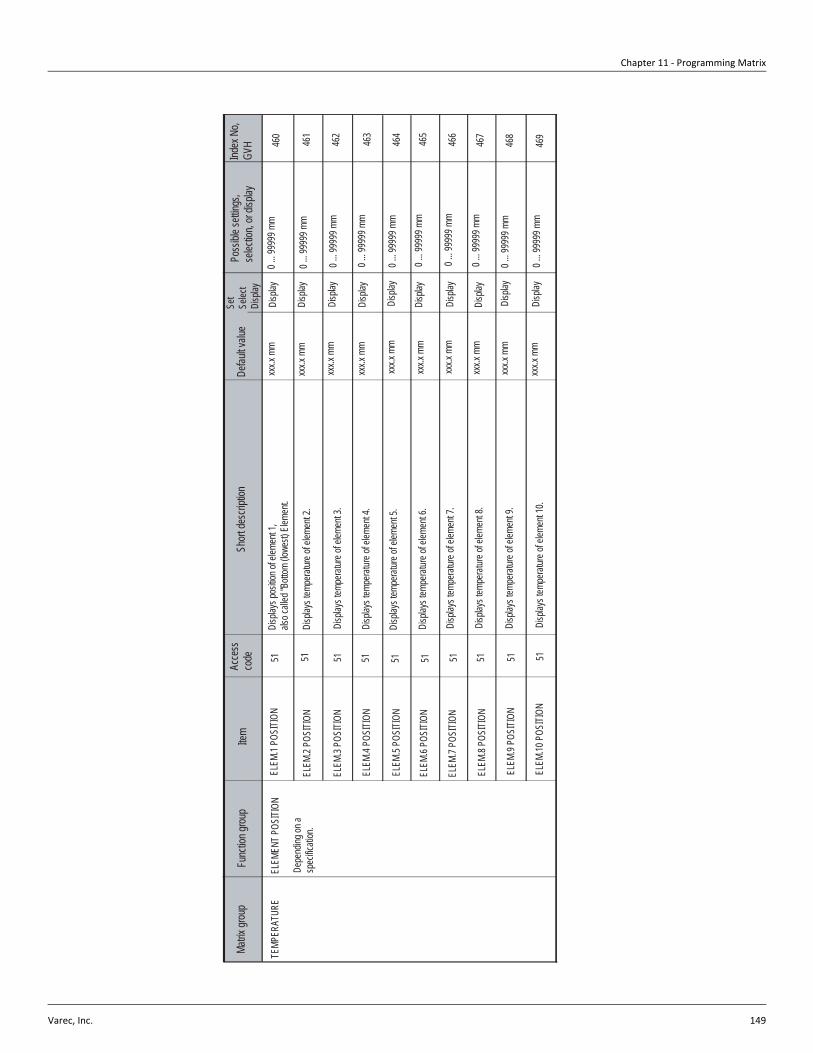
Chapter 11 - Programming Matrix
Varec, Inc. 149
Matrix
grou
pFu
nctio
n grou
pIte
mAc
cess
co
deSh
ort de
scrip
tion
Defau
lt valu
eSe
tSe
lect
Disp
lay
Poss
ible s
etting
s, se
lectio
n, or
displa
yInd
ex N
o, GV
H
ELEM
.1 PO
SITIO
N46
0
463
462
5151 51
TEMP
ERAT
URE
51
Disp
lays p
ositio
n of e
lemen
t 1,
also c
alled
"Bott
om (lo
west)
Elem
ent.
5151
xxx.x
mm
Disp
lay
Disp
lay
Disp
lay
Disp
lay
Disp
lay
Disp
lay
51
461
Disp
lays t
empe
rature
of el
emen
t 2.
Disp
lays t
empe
rature
of el
emen
t 3.
Disp
lays t
empe
rature
of el
emen
t 4.
Disp
lays t
empe
rature
of el
emen
t 5.
Disp
lays t
empe
rature
of el
emen
t 6.
Disp
lays t
empe
rature
of el
emen
t 7.
Disp
lays t
empe
rature
of el
emen
t 8.
Disp
lays t
empe
rature
of el
emen
t 9.
Disp
lays t
empe
rature
of el
emen
t 10.
Disp
lay
Disp
lay
Disp
lay
Disp
lay
51 51 51
464
465
466
467
468
469
Depe
nding
on a
spec
ificati
on.
0 ... 9
9999
mm
ELEM
ENT P
OSITI
ON
ELEM
.2 PO
SITIO
N
ELEM
.3 PO
SITIO
N
ELEM
.4 PO
SITIO
N
ELEM
.5 PO
SITIO
N
ELEM
.6 PO
SITIO
N
ELEM
.7 PO
SITIO
N
ELEM
.8 PO
SITIO
N
ELEM
.9 PO
SITIO
N
ELEM
.10 P
OSITI
ON
xxx.x
mm
xxx.x
mm
xxx.x
mm
xxx.x
mm
xxx.x
mm
xxx.x
mm
xxx.x
mm
xxx.x
mm
xxx.x
mm
0 ... 9
9999
mm
0 ... 9
9999
mm
0 ... 9
9999
mm
0 ... 9
9999
mm
0 ... 9
9999
mm
0 ... 9
9999
mm
0 ... 9
9999
mm
0 ... 9
9999
mm
0 ... 9
9999
mm

6005 Servo Tank Gauge
150 Installation and Operations Manual
Matrix
grou
pFu
nctio
n grou
pIte
mAc
cess
co
deSh
ort de
scrip
tion
Defau
lt valu
eSe
tSe
lect
Disp
lay
Poss
ible s
etting
s, se
lectio
n, or
displa
yInd
ex N
o, GV
H
NMT A
DJUS
TMEN
TSE
LECT
. POI
NT47
0
473
472
5151 51
TEMP
ERAT
URE
Selec
t elem
ent n
umbe
r for z
ero ad
justm
ent p
roced
ure.
Selec
tion b
egins
at 0,
whic
h is e
lemen
t 1. S
elect
1 for
eleme
nt 2,
etc. A
lso us
ed to
selec
t elem
ents
11-16
(inpu
t 10-1
5)
5151
Selec
t
Set
Set
Set
Set
51
471
Set g
ain ad
justm
ent v
alue f
or tem
perat
ure m
easu
rmen
t.Ca
ution
!: This
settin
g is m
ode a
t facto
ry be
fore s
hippin
g and
sh
ould
not b
e adju
sted i
n fiel
d.
Disp
lays t
empe
rature
for e
lemen
t num
ber 1
1-15
(16 el
emen
t NMT
mod
ules o
nly)
Disp
lay
Disp
lay
51
474
478
479
0
ZERO
ADJ
UST
GAIN
ADJ
UST
ELEM
ENT T
EMP
ELEM
ENT P
OSITI
ON
AVER
AGIN
G
ACCE
SS C
ODE
Set s
ampli
ng co
effifie
nt for
avera
ging d
ata. In
creas
e to c
ounte
r no
ise fa
ctor.
Disp
lays c
urren
t Acc
ess c
ode.
0.0 °C
1.000
xx.x
°C
xxx.x
mm
2
Set z
ero ad
justm
ent v
alue f
or ele
ment
selec
ted at
G4V
7H1.
Disp
lays t
empe
rature
for e
lemen
t num
ber 1
1-15
(16 el
emen
t NMT
mod
ules o
nly) w
hen s
electe
d at G
4V7H
0 Se
lect P
oint.
0-15 S
electa
ble
0(elem
ent N
o.1)
10(el
emen
t No.1
1)
-20.0
...20.0
°C
-49.9
...249
.9°C
0 ...9
9999
mm
1 ...1
0
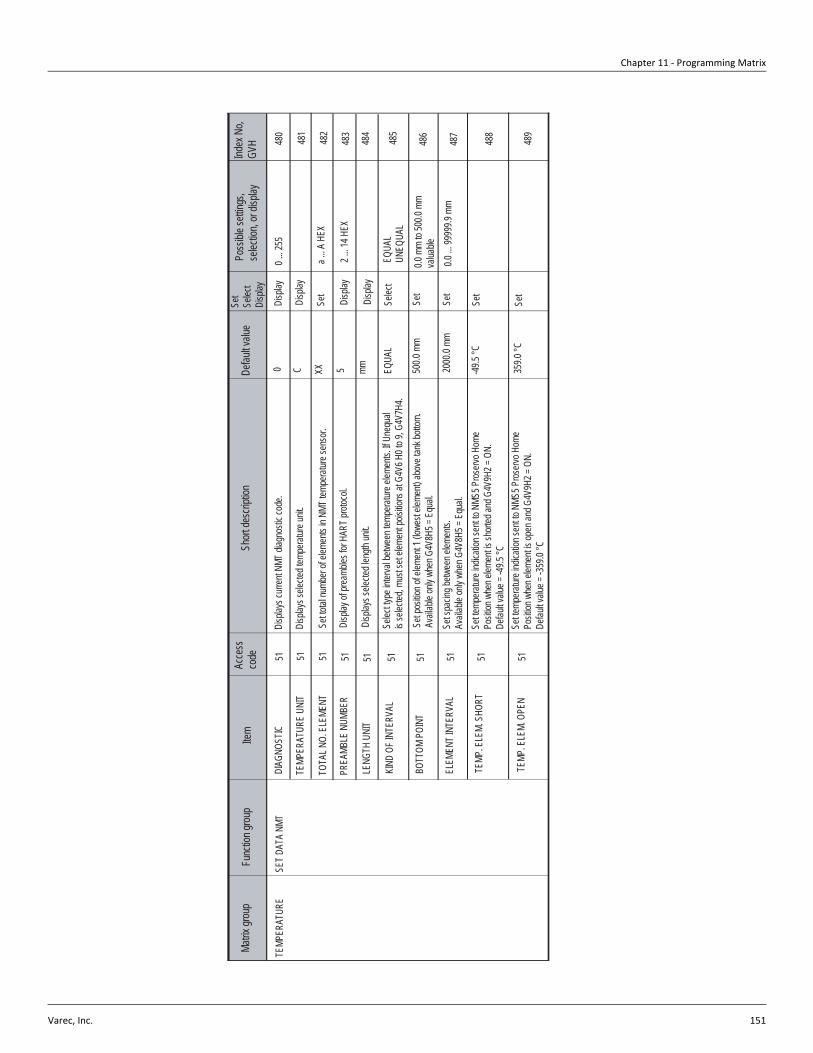
Chapter 11 - Programming Matrix
Varec, Inc. 151
Matrix
grou
pFu
nctio
n grou
pIte
mAc
cess
co
deSh
ort de
scrip
tion
Defau
lt valu
eSe
tSe
lect
Disp
lay
Poss
ible s
etting
s, se
lectio
n, or
displa
yInd
ex N
o, GV
H
SET D
ATA
NMT
DIAG
NOST
IC48
0
485
484
5151 51
TEMP
ERAT
URE
Disp
lays c
urren
t NMT
diag
nosti
c cod
e.
5151
EQUA
L
Disp
lay
Set
Disp
lay
Set
51
481
Disp
lay of
prea
mbles
for H
ART p
rotoc
ol.
Selec
t
Set
5148
6
487
488
0
TEMP
ERAT
URE
UNIT
TOTA
L NO.
ELE
MENT
PREA
MBLE
NUM
BER
LENG
TH U
NIT
KIND
OF I
NTER
VAL
BOTT
OM P
OINT
Selec
t type
inter
val b
etwee
n tem
perat
ure el
emen
ts. If
Uneq
ual
is se
lected
, mus
t set
eleme
nt po
isitio
ns at
G4V
6 H0 t
o 9, G
4V7H
4.
Set s
pacin
g betw
een e
lemen
ts.
Avail
able
only
when
G4V
8H5 =
Equ
al.20
00.0
mm
-49.5
°C
0 ...
255
a ... A
HEX
0.0 m
m to
500.0
mm
valua
ble
ELEM
ENT I
NTER
VAL
TEMP
. ELE
M. S
HORT
TEMP
. ELE
M. O
PEN
Disp
lays s
electe
d tem
perat
ure un
it.
Set to
tal nu
mber
of ele
ments
in N
MT te
mpera
ture s
enso
r.
Disp
lays s
electe
d len
gth un
it.
51
Set p
ositio
n of e
lemen
t 1 (lo
west
eleme
nt) ab
ove t
ank b
ottom
. Av
ailab
le on
ly wh
en G
4V8H
5 = E
qual.
51Se
t temp
eratur
e ind
icatio
n sen
t to N
MS5 P
roserv
o Hom
e Po
sition
whe
n elem
ent is
short
ed an
d G4V
9H2 =
ON.
De
fault v
alue =
-49.5
°C
51Se
t temp
eratur
e ind
icatio
n sen
t to N
MS5 P
roserv
o Hom
e Po
sition
whe
n elem
ent is
open
and G
4V9H
2 = O
N.
Defau
lt valu
e = -3
59.0
°C
C XX 5 mm 500.0
mm
359.0
°C
Disp
lay
Disp
lay
Set
Set
2 ... 1
4 HEX
EQUA
LUN
EQUA
L
0.0 ...
9999
9.9 m
m
482
483
489
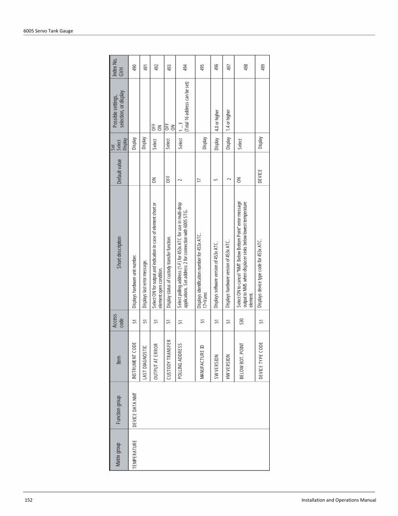
6005 Servo Tank Gauge
152 Installation and Operations Manual
Matrix
grou
pFu
nctio
n grou
pIte
mAc
cess
co
deSh
ort de
scrip
tion
Defau
lt valu
eSe
tSe
lect
Disp
lay
Poss
ible s
etting
s, se
lectio
n, or
displa
yInd
ex N
o, GV
H
DEVI
CE D
ATA
NMT
INST
RUME
NT C
ODE
490
495
494
5151 51
TEMP
ERAT
URE
Disp
lays h
ardwa
re un
it num
ber.
5151
Disp
lay
Selec
t
51
491
Disp
lay st
atus o
f cus
tody t
ransfe
r func
tion.
Disp
lay51
496
497
498
ON
LAST
DIA
GNOS
TIC
OUTP
UT A
T ERR
OR
CUST
ODY
TRAN
SFER
POLL
ING
ADDR
ESS
MANU
FACT
URE
ID
SW V
ERSI
ON
Disp
lays i
denti
ficati
on nu
mber
for 45
3x A
TC.
17=V
arec
4.0 or
high
er
BELO
W B
OT. P
OINT
HW V
ERSI
ON
DEVI
CE TY
PE C
ODE
Disp
lays l
ast e
rror m
essa
ge.
Selec
t ON
for ou
tput a
nd in
dicati
on in
case
of el
emen
t sho
rt or
eleme
nt op
en co
nditio
n.
Selec
t poll
ing ad
dress
(1-F
) for 4
53x A
TC fo
r use
in m
ulti-d
rop
appli
catio
ns. S
et ad
dress
2 for
conn
ectio
n with
6005
STG
.
51Di
splay
s soft
ware
versi
on of
453x
ATC
.
530
Selec
t ON
to ca
ncel
"NMT
Belo
w Bo
ttom
Point
" erro
r mes
sage
ou
tput to
NMS
whe
n disp
lacer
sinks
below
lowe
st tem
perat
ure
eleme
nt.
51Di
splay
s dev
ice ty
pe co
de fo
r 453
x ATC
.
2 DEVI
CE
Disp
lay
Selec
t
1.4 or
high
er
492
493
499
Disp
lays h
ardwa
re ve
rsion
of 45
3x A
TC.
OFF
ONOF
FOF
FON
17 5 2 ON
Selec
t
Disp
lay
Disp
lay
Selec
t
Disp
lay
1 ... F
(T
otal 1
6 add
ress c
an be
set)

Chapter 11 - Programming Matrix
Varec, Inc. 153
Matrix
grou
pFu
nctio
n grou
pIte
mAc
cess
co
deSh
ort de
scrip
tion
Defau
lt valu
eSe
tSe
lect
Disp
lay
Poss
ible s
etting
s, se
lectio
n, or
displa
yInd
ex N
o, GV
H
MEAS
URED
VAL
UEPV
DAT
A54
0
P.V.
RANG
E UN
IT
HART
DEV
ICE
Disp
lays p
rimary
varia
ble da
ta of
the H
ART D
evice
.Di
splay
541
SV D
ATA
Disp
lay
549
OFF
LIQUI
D TE
MP.
GAS
TEMP
ERAT
URE
ON
Selec
t
Disp
lays s
econ
dary
varia
ble da
ta of
the H
ART D
evice
.
HART
DEV
ICE
(1)Se
lect H
ART D
evice
1 fun
ction
: OFF
, ON,
Liqu
id Te
mpera
ture,
Gas T
empe
rature
. If "L
iquid
Temp
eratur
e" is
selec
ted, v
alue i
s ref
lected
at G
0V1H
0 and
G0V
1H1
OFF
P.V.
SETT
ING
P.V.
UPPE
R RA
NGE
P.V.
LOW
ER R
ANGE
DAMP
VAL
UE
51 51 51 51 51
Settin
g of u
pper
range
of pr
imary
varia
ble.
Settin
g of ra
nge u
nit fo
r prim
ary va
riable
in
HART
comm
and c
ode.
Settin
g of lo
wer r
ange
of pr
imary
varia
ble.
Settin
g of d
ampin
g of p
rimary
varia
ble.
SENS
OR S
PECI
FICSE
NSOR
SER
IAL N
O
UPPE
R SE
NSOR
LMT
LOW
ER S
ENSO
R LM
T
Disp
alys s
enso
r seri
al nu
mber
Disp
alys u
pper
limit o
f the H
ART D
evice
.
Disp
alys u
pper
limit o
f the H
ART D
evice
.
Set
Set
Set
Set
Disp
lay
Disp
lay
Disp
lay
550
551
552
553
560
561
562

6005 Servo Tank Gauge
154 Installation and Operations Manual
Matrix
grou
pFu
nctio
n grou
pIte
mAc
cess
co
deSh
ort de
scrip
tion
Defau
lt valu
eSe
tSe
lect
Disp
lay
Poss
ible s
etting
s, se
lectio
n, or
displa
yInd
ex N
o, GV
H
SELF
DIA
GNIS
TICER
ROR
CODE
(1)
580
POLL
ING
ADDR
ESS
HART
DEV
ICE
Disp
lays o
f the e
rror c
ode (
1) the
HAR
T dev
ice.
Disp
lay
581
ERRO
R CO
DE (2
)Di
splay
582
DEVI
CE D
ATA
MANU
FACT
URE
ID
DEVI
CE TY
PE C
ODE
PREA
MBLE
S
Disp
lays m
anufa
cturer
ID nu
mber
of the
HAR
T Dev
ice.
Disp
lays p
olling
addre
ss of
HAR
T Dev
ice 1.
Add
ress (
fixed
) = 4.
Disp
lays d
evice
type
code
of th
e HAR
T Dev
ice.
Set n
umbe
r of p
reamb
les fo
r the H
ART d
evice
.
SW V
ERSI
ON
HW V
ERSI
ON
DEVI
CE ID
Disp
alys t
he so
ftware
versi
on fo
r the H
ART d
evice
.
Disp
lay
Disp
lay
Disp
lay
583
584
591
592
593
597
ERRO
R CO
DE (3
)
ERRO
R CO
DE (4
)
ERRO
R CO
DE (5
)
Cons
ult H
ART d
evice
opera
tion/s
ervice
man
ual
Disp
lays o
f the e
rror c
ode (
2) the
HAR
T dev
ice.
Disp
lays o
f the e
rror c
ode (
3) the
HAR
T dev
ice.
Disp
lays o
f the e
rror c
ode (
4) the
HAR
T dev
ice.
Disp
lays o
f the e
rror c
ode (
5) the
HAR
T dev
ice.
Disp
alys t
he ha
rdware
versi
on fo
r the H
ART d
evice
.
Disp
lays t
he de
vice I
D for
the H
ART d
evice
.
Disp
lay
Disp
lay
Disp
lay
Disp
lay
Disp
lay
Disp
lay
Disp
lay
594
595
596
4
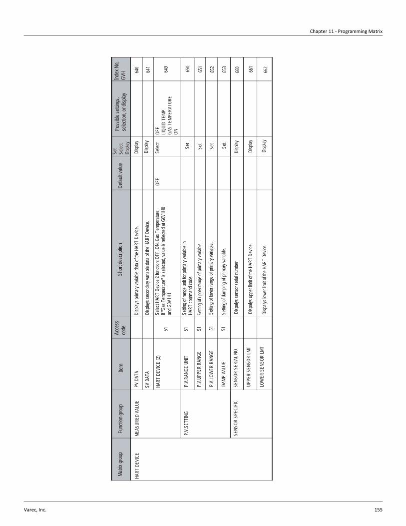
Chapter 11 - Programming Matrix
Varec, Inc. 155
Matrix
grou
pFu
nctio
n grou
pIte
mAc
cess
co
deSh
ort de
scrip
tion
Defau
lt valu
eSe
tSe
lect
Disp
lay
Poss
ible s
etting
s, se
lectio
n, or
displa
yInd
ex N
o, GV
H
MEAS
URED
VAL
UEPV
DAT
A64
0
P.V.
RANG
E UN
IT
HART
DEV
ICE
Disp
lays p
rimary
varia
ble da
ta of
the H
ART D
evice
.Di
splay
641
SV D
ATA
Disp
lay
649
OFF
LIQUI
D TE
MP.
GAS
TEMP
ERAT
URE
ON
Selec
t
Disp
lays s
econ
dary
varia
ble da
ta of
the H
ART D
evice
.
HART
DEV
ICE
(2)Se
lect H
ART D
evice
2 fun
ction
: OFF
, ON,
Gas
Temp
eratur
e.If "
Gas T
empe
rature
" is se
lected
, valu
e is r
eflec
ted at
G0V
1H0
and G
0V1H
1
OFF
P.V.
SETT
ING
P.V.
UPPE
R RA
NGE
P.V.
LOW
ER R
ANGE
DAMP
VAL
UE
51 51 51 51 51
Settin
g of u
pper
range
of pr
imary
varia
ble.
Settin
g of ra
nge u
nit fo
r prim
ary va
riable
in
HART
comm
and c
ode.
Settin
g of lo
wer r
ange
of pr
imary
varia
ble.
Settin
g of d
ampin
g of p
rimary
varia
ble.
SENS
OR S
PECI
FICSE
NSOR
SER
IAL N
O
UPPE
R SE
NSOR
LMT
LOW
ER S
ENSO
R LM
T
Disp
alys s
enso
r seri
al nu
mber
Disp
alys u
pper
limit o
f the H
ART D
evice
.
Disp
alys l
ower
limit o
f the H
ART D
evice
.
Set
Set
Set
Set
Disp
lay
Disp
lay
Disp
lay
650
651
652
653
660
661
662

6005 Servo Tank Gauge
156 Installation and Operations Manual
Matrix
grou
pFu
nctio
n grou
pIte
mAc
cess
co
deSh
ort de
scrip
tion
Defau
lt valu
eSe
tSe
lect
Disp
lay
Poss
ible s
etting
s, se
lectio
n, or
displa
yInd
ex N
o, GV
H
SELF
DIA
GNIS
TICER
ROR
CODE
(1)
680
POLL
ING
ADDR
ESS
HART
DEV
ICE
Disp
lays o
f the e
rror c
ode (
1) the
HAR
T dev
ice.
Disp
lay
681
ERRO
R CO
DE (2
)Di
splay
682
DEVI
CE D
ATA
MANU
FACT
URE
ID
DEVI
CE TY
PE C
ODE
PREA
MBLE
S
Disp
lays m
anufa
cturer
ID nu
mber
of the
HAR
T Dev
ice.
Disp
lays p
olling
addre
ss of
HAR
T Dev
ice 2.
Add
ress (
fixed
) = 5.
Disp
lays d
evice
type
code
of th
e HAR
T Dev
ice.
Set n
umbe
r of p
reamb
les fo
r the H
ART d
evice
.
SW V
ERSI
ON
HW V
ERSI
ON
DEVI
CE ID
Disp
alys t
he so
ftware
versi
on fo
r the H
ART d
evice
.
Disp
lay
Disp
lay
Disp
lay
683
684
691
692
693
697
ERRO
R CO
DE (3
)
ERRO
R CO
DE (4
)
ERRO
R CO
DE (5
)
Cons
ult H
ART d
evice
opera
tion/s
ervice
man
ual
Disp
lays o
f the e
rror c
ode (
2) the
HAR
T dev
ice.
Disp
lays o
f the e
rror c
ode (
3) the
HAR
T dev
ice.
Disp
lays o
f the e
rror c
ode (
4) the
HAR
T dev
ice.
Disp
lays o
f the e
rror c
ode (
5) the
HAR
T dev
ice.
Disp
alys t
he ha
rdware
versi
on fo
r the H
ART d
evice
.
Disp
lays t
he de
vice I
D for
the H
ART d
evice
.
Disp
lay
Disp
lay
Disp
lay
Set
Disp
lay
Disp
lay
Disp
lay
694
695
696
5

Chapter 11 - Programming Matrix
Varec, Inc. 157
Matrix
grou
pFu
nctio
n grou
pIte
mAc
cess
co
deSh
ort de
scrip
tion
Defau
lt valu
eSe
tSe
lect
Disp
lay
Poss
ible s
etting
s, se
lectio
n, or
displa
yInd
ex N
o, GV
H
ADJ.
SENS
OR
Selec
t unit
s for
tempe
rature
data
displa
yed l
ocall
y at N
6005
/N46
50
UNIT
LEV.
UNI
T (HO
ST)
TEMP
UNI
T (HO
ST)
DEN.
UNI
T (HO
ST)
Selec
t disp
lay un
its fo
r leve
l valu
e data
to be
sent
to ho
st CP
U via
remo
te co
mmun
icatio
ns76
0
761
LEV.
UNI
T
TEMP
. UNI
T
DEN.
UNI
T
Selec
t unit
s for
tempe
rature
value
data
to be
sent
to ho
st CP
U via
remo
te co
mmun
icatio
nsSe
lect d
isplay
units
for d
ensit
y valu
e data
to be
sent
to ho
st CP
U via
remo
te co
mmun
icatio
nsSe
lect u
nits f
or lev
el va
lue da
ta dis
playe
d loc
ally a
t N60
05/N
4650
Selec
t unit
s for
dens
ity va
lue da
ta dis
playe
d loc
ally a
t N60
05/N
4650
51 51
mm °C g/mL
51
mm °C g/mL
51 51 51
Selec
t
Selec
t
Selec
t
Selec
t
Selec
t
Selec
t
m, in
ch, c
m, ft
°C, °
F, °R
, °K
Kg/m
, lb/g
l, SGU
, Kg/l
,g/l
, lb/in
, st/y
3
3
m, in
ch, c
m, ft
°C, °
F, °R
, °K
Kg/m
, lb/g
l, SGU
, Kg/l
,g/l
, lb/in
, st/y
762
765
766
767
HART
LINE
NMT
770
Selec
t Term
inal P
ort A
(Ex i
a) or
Term
inal P
ort B
(Ex d
) for
the 45
3x co
nnec
tion
15
Set
771
Set
772
Set
INTE
RFAC
E AD
JUST
BALA
NCE
COUN
T
IF 2 O
FFSE
T
777
780
781
782
783
784
HART
DEV
ICE
(1)
HART
DEV
ICE
(2)
777
777
51Se
t Volu
me To
leran
ce fo
r Bala
nce c
ondit
ion du
ring I
nterfa
ce
meas
ureme
ntUs
ed fo
r Inter
face M
easu
remen
t. Inc
rease
Brak
e Rate
to m
ake t
heba
lance
zone
small
er an
d dec
rease
inter
face m
easu
remen
t time
.
0.0 m
m
0.0 m
m
Set
Disp
lay
Disp
lay
Disp
lay
Disp
lay
VOL.
TOL.
FOR
I/F
BRAK
E RA
TE
IF 1 O
FFSE
T
Selec
t Term
inal P
ort A
(Ex i
a) or
Term
inal P
ort B
(Ex d
) for
the H
ART D
evice
1.Se
lect T
ermina
l Port
A (E
x ia)
or Te
rmina
l Port
B (E
x d) fo
rthe
HAR
T Dev
ice 2.
51 51 51 51
Used
for In
terfac
e Mea
surem
ent. B
alanc
e sign
al is
gene
rated
after
motor
mov
emen
t cha
nges
from
fast to
slow
spec
ified n
umbe
r of
times
. Coo
rdina
te thi
s sett
ing w
ith G
2V9H
9 Bala
nce D
elay s
etting
.
Chan
ge th
is se
tting t
o corr
ect In
terfac
e 1 le
vel d
eviat
ion.
Chan
ge th
is se
tting t
o corr
ect In
terfac
e 2 le
vel d
eviat
ion.
TERM
INAL
PO
RT B
TERM
INAL
PO
RT B
TERM
INAL
PO
RT B
TERM
INAL
POR
T BTE
RMIN
AL P
ORT A
TERM
INAL
POR
T BTE
RMIN
AL P
ORT A
TERM
INAL
POR
T BTE
RMIN
AL P
ORT A
0.3 m
L
150
0 - 99
.9 mL
0 - 25
5
0 - 25
5
0 - 99
99.9
mm
0 - 99
99.9
mm
ADJ
A ZE
RO
ADJ
A ZE
RO
ADJ
B S
PAN
ADJ
B S
PAN
530
530
530
530
Hall
Sen
sor A
Zer
o sign
al
Hall
Sen
sor A
Zer
o sign
al
Hall
Sen
sor B
Full
span
sign
al
Hall
Sen
sor B
Full
span
sign
al
Disp
lay
Disp
lay
Disp
lay
Disp
lay
740
741
742
743
ADJ.
SENS
OR
HART
ERR
OR R
ATE
ERR
. RAT
E NR
F
ERR
. RAT
E NM
T
ERR.
RAT
E DE
V(1)
ERR.
RAT
E DE
V(2)
530
530
530
530
Comm
unica
tion e
rror r
ate
Comm
unica
tion e
rror r
ate
Comm
unica
tion e
rror r
ate
Comm
unica
tion e
rror r
ate
Disp
lay
Disp
lay
Disp
lay
Disp
lay
750
751
752
753
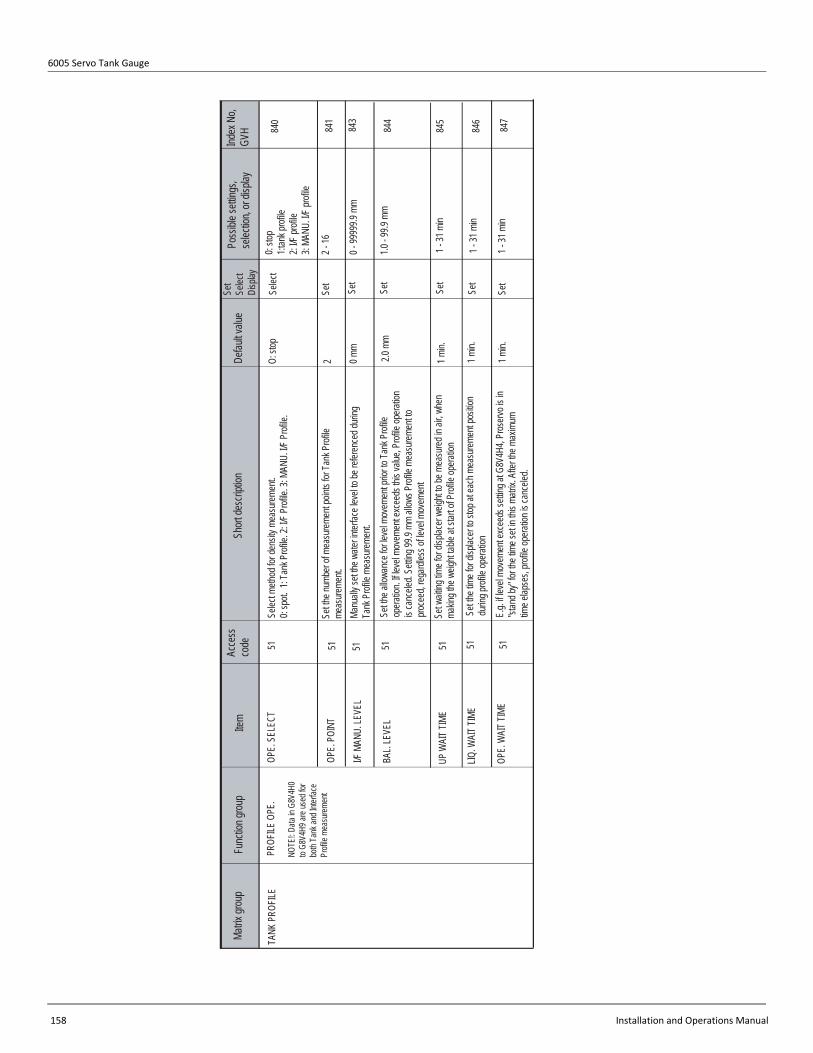
6005 Servo Tank Gauge
158 Installation and Operations Manual
Matrix
grou
pFu
nctio
n grou
pIte
mAc
cess
co
deSh
ort de
scrip
tion
Defau
lt valu
eSe
tSe
lect
Disp
lay
Poss
ible s
etting
s, se
lectio
n, or
displa
yInd
ex N
o, GV
H
OPE.
SEL
ECT
840
51
TANK
PRO
FILE
1 min.
Selec
t
841
Set
843
Set
844
846
847
OPE.
POI
NT
I/F M
ANU.
LEVE
L
51
1 min.
Set
BAL.
LEVE
L
OPE.
WAI
T TIM
E
51 51 51
O: st
op
2 0 mm
2.0 m
m
PROF
ILE O
PE.
UP W
AIT T
IME
LIQ. W
AIT T
IME
NOTE
!: Data
in G
8V4H
0to
G8V4
H9 ar
e use
d for
both
Tank
and I
nterfa
ce
Profi
le me
asure
ment
Set th
e num
ber o
f mea
surem
ent p
oints
for Ta
nk P
rofile
me
asure
ment.
51Se
lect m
ethod
for d
ensit
y mea
surem
ent.
0: sp
ot. 1
: Tan
k Prof
ile. 2
: I/F P
rofile
. 3: M
ANU.
I/F P
rofile
.
51Ma
nuall
y set
the w
ater in
terfac
e lev
el to
be re
feren
ced d
uring
Ta
nk P
rofile
mea
surem
ent.
Set th
e allo
wanc
e for
level
move
ment
prior
to Ta
nk P
rofile
op
eratio
n. If l
evel
move
ment
exce
eds t
his va
lue, P
rofile
opera
tion
is ca
ncele
d. Se
tting 9
9.9 m
m all
ows P
rofile
mea
surem
ent to
pro
ceed
, rega
rdles
s of le
vel m
ovem
ent
Set w
aiting
time f
or dis
place
r weig
ht to
be m
easu
red in
air, w
hen
makin
g the
weig
ht tab
le at
start o
f Prof
ile op
eratio
n
Set th
e tim
e for
displa
cer to
stop
at ea
ch m
easu
remen
t pos
ition
durin
g prof
ile op
eratio
n
E.g.
if lev
el mo
veme
nt ex
ceed
s sett
ing at
G8V
4H4,
Pros
ervo i
s in
"stan
d by"
for th
e tim
e set
in thi
s matr
ix. A
fter th
e max
imum
time e
lapse
s, pro
file op
eratio
n is c
ance
led.
1 min.
Set
Set
Set
0: sto
p1:t
ank p
rofile
2: I/F
profi
le3:
MANU
. I/F p
rofile
2 - 16
0 - 99
999.9
mm
1.0 - 9
9.9 m
m
1 - 31
min
1 - 31
min
1 - 31
min
845

Chapter 11 - Programming Matrix
Varec, Inc. 159
Matrix
grou
pFu
nctio
n grou
pIte
mAc
cess
co
deSh
ort de
scrip
tion
Defau
lt valu
eSe
tSe
lect
Disp
lay
Poss
ible s
etting
s, se
lectio
n, or
displa
yInd
ex N
o, GV
H
OPE.
STA
TUS
850
TANK
PRO
FILE
851
852
854
855
LEVE
L CON
DITIO
N
OPE.
TIME
AVER
AGE
DENS
ITY
0 0 DDHH
MM
0.000
g/ml
STAR
US/D
ATA
AVER
AGE
TEMP
.
DIAG
. COD
E
Disp
lays s
tatus
of liq
uid le
vel/s
urfac
e mon
itored
prior
topro
file op
eratio
n.
0.0 °C
0 - 4
0000
000 -
3123
59
0.000
- 9.99
9 g/m
l
858
Disp
lays p
rofile
opera
tion s
tatus
.0:
Acce
pting
1: St
andb
y2:
In op
eratio
n3:
OPR.
END
4: UN
_BAL
ANCE
ERR
5: OP
R. E
RR. S
TOP
Acce
pting
dens
ity pr
ofile
comm
and
Read
y to e
xecu
te de
nsity
profi
le co
mman
dEx
ecuti
ng de
nsity
profi
le co
mman
dDe
nsity
profi
le op
eratio
n com
pleted
succ
essfu
llyFa
il: Re
quire
d con
dition
s for
dens
ity pr
ofile
opera
tion n
ot sa
tisfie
dFa
il: Ab
norm
al co
nditio
ns oc
curre
d duri
ng
dens
ity pr
ofile
opera
tion
0: Of
f Lev
el Me
as1:
Stab
le2:
Unsta
ble
3: Ign
or Co
nditio
n
Activ
e ope
ration
is no
t LEV
EL (p
rofile
cann
ot sta
rt)
Liquid
leve
l/surf
ace i
s stab
le (pr
ofile
can s
tart)
Liquid
leve
l/surf
ace i
s uns
table
(profi
le ca
nnot
start)
Ignore
s liqu
id lev
el/su
rface
cond
ition
(profi
le ca
nnot
start)
Disp
lays t
ime w
hen T
ank P
rofile
opera
tion f
inish
ed(D
D/HH
/MM)
Disp
lays a
verag
e tem
perat
ure va
lue
Disp
lays a
verag
e den
sity v
alue
Disp
lay
Disp
lay
Disp
lay
Disp
lay
Disp
lay0 -
6
0 -03
59.5
°C

6005 Servo Tank Gauge
160 Installation and Operations Manual
Matrix
grou
pFu
nctio
n grou
pIte
mAc
cess
co
deSh
ort de
scrip
tion
Defau
lt valu
eSe
tSe
lect
Disp
lay
Poss
ible s
etting
s, se
lectio
n, or
displa
yInd
ex N
o, GV
H
DENS
ITY1 -
10NO
. 1 D
ENSI
TY86
0TA
NK P
ROFIL
EDi
splay
861
NO. 2
DEN
SITY
Disp
lay
862
Disp
lay
Disp
lay
Disp
lay
863
864
865
866
867
Disp
lay
Disp
lay
Disp
lay
Disp
lay
Disp
lay
868
869
NO. 3
DEN
SITY
NO. 4
DEN
SITY
NO. 5
DEN
SITY
NO. 6
DEN
SITY
NO. 7
DEN
SITY
NO. 8
DEN
SITY
NO. 9
DEN
SITY
NO. 1
0 DEN
SITY
Disp
lays d
ensit
y valu
es fo
r poin
t No.1
in de
nsity
profi
le
Disp
lays d
ensit
y valu
es fo
r poin
t No.2
in de
nsity
profi
le
Disp
lays d
ensit
y valu
es fo
r poin
t No.3
in de
nsity
profi
le
Disp
lays d
ensit
y valu
es fo
r poin
t No.4
in de
nsity
profi
le
Disp
lays d
ensit
y valu
es fo
r poin
t No.5
in de
nsity
profi
le
Disp
lays d
ensit
y valu
es fo
r poin
t No.6
in de
nsity
profi
le
Disp
lays d
ensit
y valu
es fo
r poin
t No.7
in de
nsity
profi
le
Disp
lays d
ensit
y valu
es fo
r poin
t No.8
in de
nsity
profi
le
Disp
lays d
ensit
y valu
es fo
r poin
t No.9
in de
nsity
profi
le
Disp
lays d
ensit
y valu
es fo
r poin
t No.1
0 in d
ensit
y prof
ile
0.000
g/ml
0.000
g/ml
0.000
g/ml
0.000
g/ml
0.000
g/ml
0.000
g/ml
0.000
g/ml
0.000
g/ml
0.000
g/ml
0.000
g/ml
0.000
- 9.99
9 g/m
l
0.000
- 9.99
9 g/m
l
0.000
- 9.99
9 g/m
l
0.000
- 9.99
9 g/m
l
0.000
- 9.99
9 g/m
l
0.000
- 9.99
9 g/m
l
0.000
- 9.99
9 g/m
l
0.000
- 9.99
9 g/m
l
0.000
- 9.99
9 g/m
l
0.000
- 9.99
9 g/m
l
NO. 1
1 DEN
SITY
870
Disp
lay
871
NO. 1
2 DEN
SITY
Disp
lay
872
Disp
lay
Disp
lay
873
874
875
Disp
lay
Disp
lay
NO. 1
3 DEN
SITY
NO. 1
4 DEN
SITY
NO. 1
5 DEN
SITY
NO. 1
6 DEN
SITY
Disp
lays d
ensit
y valu
es fo
r poin
t No.1
1 in d
ensit
y prof
ile
Disp
lays d
ensit
y valu
es fo
r poin
t No.1
2 in d
ensit
y prof
ile
Disp
lays d
ensit
y valu
es fo
r poin
t No.1
3 in d
ensit
y prof
ile
Disp
lays d
ensit
y valu
es fo
r poin
t No.1
4 in d
ensit
y prof
ile
Disp
lays d
ensit
y valu
es fo
r poin
t No.1
5 in d
ensit
y prof
ile
Disp
lays d
ensit
y valu
es fo
r poin
t No.1
6 in d
ensit
y prof
ile
0.000
g/ml
0.000
g/ml
0.000
g/ml
0.000
g/ml
0.000
g/ml
0.000
g/ml
0.000
- 9.99
9 g/m
l
0.000
- 9.99
9 g/m
l
0.000
- 9.99
9 g/m
l
0.000
- 9.99
9 g/m
l
0.000
- 9.99
9 g/m
l
0.000
- 9.99
9 g/m
l
DENS
ITY11
- 16

Chapter 11 - Programming Matrix
Varec, Inc. 161
Matrix
grou
pFu
nctio
n grou
pIte
mAc
cess
co
deSh
ort de
scrip
tion
Defau
lt valu
eSe
tSe
lect
Disp
lay
Poss
ible s
etting
s, se
lectio
n, or
displa
yInd
ex N
o, GV
H
OPE.
STA
TUS
950
INTE
RFAC
EPR
OFILE
951
952
953
954
LEVE
L CON
DITIO
N
OPE.
TIME
AVER
AGE
DENS
ITY
0 0 DDHH
MM
0.000
g/ml
STAT
US/D
ATA
AVER
AGE
TEMP
.
Disp
lays s
tatus
of liq
uid le
vel/s
urfac
e mon
itored
prior
topro
file op
eratio
n.
0.0 °C
0 - 4
0000
000 -
3123
59
0.000
- 9.99
9 g/m
l
955
Disp
lays p
rofile
opera
tion s
tatus
.0:
Acce
pting
1: St
andb
y2:
In op
eratio
n3:
OPR.
END
4: UN
_BAL
ANCE
ERR
5: OP
R. E
RR. S
TOP
Acce
pting
dens
ity pr
ofile
comm
and
Read
y to e
xecu
te de
nsity
profi
le co
mman
dEx
ecuti
ng de
nsity
profi
le co
mman
dDe
nsity
profi
le op
eratio
n com
pleted
succ
essfu
llyFa
il: Re
quire
d con
dition
s for
dens
ity pr
ofile
opera
tion n
ot sa
tisfie
dFa
il: Ab
norm
al co
nditio
ns oc
curre
d duri
ng
dens
ity pr
ofile
opera
tion
0: Of
f Lev
el Me
as1:
Stab
le2:
Unsta
ble
3: Ign
or Co
nditio
n
Activ
e ope
ration
is no
t LEV
EL (p
rofile
cann
ot sta
rt)
Liquid
leve
l/surf
ace i
s stab
le (pr
ofile
can s
tart)
Liquid
leve
l/surf
ace i
s uns
table
(profi
le ca
nnot
start)
Ignore
s liqu
id lev
el/su
rface
cond
ition
(profi
le ca
nnot
start)
Disp
lays t
ime w
hen I
nterfa
ce P
rofile
opera
tion f
inish
ed(D
D/HH
/MM)
.
Disp
lays a
verag
e den
sity v
alue c
alcula
ted fro
m Int
erfac
e Prof
ile
meas
ureme
nt.
Disp
lays I
nterfa
ce le
vel u
sed f
or Int
erfac
e Prof
ile m
easu
remen
t.
Disp
aly
Disp
lay
Disp
lay
Disp
lay
Disp
lay0 -
6
0 -35
9.5 °C
I/F LE
VEL
Disp
lays a
varag
e tem
perat
ure va
lue ca
lculat
ed fro
m Int
erfac
e Pr
ofile
meas
ureme
nt.

6005 Servo Tank Gauge
162 Installation and Operations Manual
Matrix
grou
pFu
nctio
n grou
pIte
mAc
cess
co
deSh
ort de
scrip
tion
Defau
lt valu
eSe
tSe
lect
Disp
lay
Poss
ible s
etting
s, se
lectio
n, or
displa
yInd
ex N
o, GV
H
DENS
ITY1 -
10NO
. 1 D
ENSI
TY96
0TA
NK P
ROFIL
EDi
splay
961
NO. 2
DEN
SITY
Disp
lay
962
Disp
lay
Disp
lay
Disp
lay
963
964
965
966
967
Disp
lay
Disp
lay
Disp
lay
Disp
lay
Disp
lay
968
969
NO. 3
DEN
SITY
NO. 4
DEN
SITY
NO. 5
DEN
SITY
NO. 6
DEN
SITY
NO. 7
DEN
SITY
NO. 8
DEN
SITY
NO. 9
DEN
SITY
NO. 1
0 DEN
SITY
Disp
lays d
ensit
y valu
es fo
r poin
t No.1
in de
nsity
profi
le
Disp
lays d
ensit
y valu
es fo
r poin
t No.2
in de
nsity
profi
le
Disp
lays d
ensit
y valu
es fo
r poin
t No.3
in de
nsity
profi
le
Disp
lays d
ensit
y valu
es fo
r poin
t No.4
in de
nsity
profi
le
Disp
lays d
ensit
y valu
es fo
r poin
t No.5
in de
nsity
profi
le
Disp
lays d
ensit
y valu
es fo
r poin
t No.6
in de
nsity
profi
le
Disp
lays d
ensit
y valu
es fo
r poin
t No.7
in de
nsity
profi
le
Disp
lays d
ensit
y valu
es fo
r poin
t No.8
in de
nsity
profi
le
Disp
lays d
ensit
y valu
es fo
r poin
t No.9
in de
nsity
profi
le
Disp
lays d
ensit
y valu
es fo
r poin
t No.1
0 in d
ensit
y prof
ile
0.000
g/ml
0.000
g/ml
0.000
g/ml
0.000
g/ml
0.000
g/ml
0.000
g/ml
0.000
g/ml
0.000
g/ml
0.000
g/ml
0.000
g/ml
0.000
- 9.99
9 g/m
l
0.000
- 9.99
9 g/m
l
0.000
- 9.99
9 g/m
l
0.000
- 9.99
9 g/m
l
0.000
- 9.99
9 g/m
l
0.000
- 9.99
9 g/m
l
0.000
- 9.99
9 g/m
l
0.000
- 9.99
9 g/m
l
0.000
- 9.99
9 g/m
l
0.000
- 9.99
9 g/m
l
NO. 1
1 DEN
SITY
970
Disp
lay
971
NO. 1
2 DEN
SITY
Disp
lay
972
Disp
lay
Disp
lay
973
974
975
Disp
lay
Disp
lay
NO. 1
3 DEN
SITY
NO. 1
4 DEN
SITY
NO. 1
5 DEN
SITY
NO. 1
6 DEN
SITY
Disp
lays d
ensit
y valu
es fo
r poin
t No.1
1 in d
ensit
y prof
ile
Disp
lays d
ensit
y valu
es fo
r poin
t No.1
2 in d
ensit
y prof
ile
Disp
lays d
ensit
y valu
es fo
r poin
t No.1
3 in d
ensit
y prof
ile
Disp
lays d
ensit
y valu
es fo
r poin
t No.1
4 in d
ensit
y prof
ile
Disp
lays d
ensit
y valu
es fo
r poin
t No.1
5 in d
ensit
y prof
ile
Disp
lays d
ensit
y valu
es fo
r poin
t No.1
6 in d
ensit
y prof
ile
0.000
g/ml
0.000
g/ml
0.000
g/ml
0.000
g/ml
0.000
g/ml
0.000
g/ml
0.000
- 9.99
9 g/m
l
0.000
- 9.99
9 g/m
l
0.000
- 9.99
9 g/m
l
0.000
- 9.99
9 g/m
l
0.000
- 9.99
9 g/m
l
0.000
- 9.99
9 g/m
l
DENS
ITY11
- 16
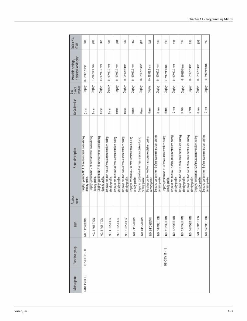
Chapter 11 - Programming Matrix
Varec, Inc. 163
Matrix
grou
pFu
nctio
n grou
pIte
mAc
cess
co
deSh
ort de
scrip
tion
Defau
lt valu
eSe
tSe
lect
Disp
lay
Poss
ible s
etting
s, se
lectio
n, or
displa
yInd
ex N
o, GV
H
POSI
TION1
- 10
NO. 1
POS
ITION
980
TANK
PRO
FILE
Disp
lay
981
Disp
lay
982
Disp
lay
Disp
lay
Disp
lay
983
984
985
986
987
Disp
lay
Disp
lay
Disp
lay
Disp
lay
Disp
lay
988
989
Disp
lays p
ositio
n No.1
of m
easu
remen
t take
n duri
ng
dens
ity pr
ofile.
0 mm
0 mm
0 mm
0 mm
0 mm
0 mm
0 mm
0 mm
0 mm
0 mm
0 - 99
999.9
mm
990
Disp
lay
991
Disp
lay
992
Disp
lay
Disp
lay
993
994
995
Disp
lay
Disp
lay
0 mm
0 mm
0 mm
0 mm
0 mm
0 mm
DENS
ITY11
- 16
NO. 2
POS
ITION
NO. 3
POS
ITION
NO. 4
POS
ITION
NO. 5
POS
ITION
NO. 6
POS
ITION
NO. 7
POS
ITION
NO. 8
POS
ITION
NO. 9
POS
ITION
NO. 1
0 POS
ITION
NO. 1
1 POS
ITION
NO. 1
2 POS
ITION
NO. 1
3 POS
ITION
NO. 1
4 POS
ITION
NO. 1
5 POS
ITION
NO. 1
6 POS
ITION
Disp
lays p
ositio
n No.2
of m
easu
remen
t take
n duri
ng
dens
ity pr
ofile.
Disp
lays p
ositio
n No.3
of m
easu
remen
t take
n duri
ng
dens
ity pr
ofile.
Disp
lays p
ositio
n No.4
of m
easu
remen
t take
n duri
ng
dens
ity pr
ofile.
Disp
lays p
ositio
n No.5
of m
easu
remen
t take
n duri
ng
dens
ity pr
ofile.
Disp
lays p
ositio
n No.6
of m
easu
remen
t take
n duri
ng
dens
ity pr
ofile.
Disp
lays p
ositio
n No.7
of m
easu
remen
t take
n duri
ng
dens
ity pr
ofile.
Disp
lays p
ositio
n No.8
of m
easu
remen
t take
n duri
ng
dens
ity pr
ofile.
Disp
lays p
ositio
n No.9
of m
easu
remen
t take
n duri
ng
dens
ity pr
ofile.
Disp
lays p
ositio
n No.1
0 of m
easu
remen
t take
n duri
ng
dens
ity pr
ofile.
Disp
lays p
ositio
n No.1
1 of m
easu
remen
t take
n duri
ng
dens
ity pr
ofile.
Disp
lays p
ositio
n No.1
2 of m
easu
remen
t take
n duri
ng
dens
ity pr
ofile.
Disp
lays p
ositio
n No.1
3 of m
easu
remen
t take
n duri
ng
dens
ity pr
ofile.
Disp
lays p
ositio
n No.1
4 of m
easu
remen
t take
n duri
ng
dens
ity pr
ofile.
Disp
lays p
ositio
n No.1
5 of m
easu
remen
t take
n duri
ng
dens
ity pr
ofile.
Disp
lays p
ositio
n No.1
6 of m
easu
remen
t take
n duri
ng
dens
ity pr
ofile.
0 - 99
999.9
mm
0 - 99
999.9
mm
0 - 99
999.9
mm
0 - 99
999.9
mm
0 - 99
999.9
mm
0 - 99
999.9
mm
0 - 99
999.9
mm
0 - 99
999.9
mm
0 - 99
999.9
mm
0 - 99
999.9
mm
0 - 99
999.9
mm
0 - 99
999.9
mm
0 - 99
999.9
mm
0 - 99
999.9
mm
0 - 99
999.9
mm

6005 Servo Tank Gauge
164 Installation and Operations Manual

Varec, Inc. 165
Chapter 12
Technical Data
Measuring range from 0 to 16, 28, or 36m depending on material specification(longer ranges available upon consultation)
Density limits 0.430 to 2.000 g/cm3 (430 to 2000 kg/m3)
Accuracy Level: +/- 0.7mm (0.027 inch) *1
Interface: +/- 2.7mm (0.106 inch)*2
Density: +/- 0.005 g/cm3 *3
Sensitivity +/- 0.1mm (0.004 inch)
Self-diagnostic function CPU system health, measuring wire tension, communication, gauge status, level data input, etc
Input/Output See "Ordering Information" on page 169.
Motion delay Configurable in 20ms steps from 0 to 9.9 seconds
Power 85 to 264 VAC, 50/60 Hz20 to 62 VDC, or 20 to 55 VAC, 50/60Hz
Max. current 50VA / 50W
Surge protection Standard supply
Ambient Temperature -20º to 60º C (-4 to 140ºF)-40º to 60º C (-14 to 140º F) ATEX approval cold temperature version
Liquid Temperature -200º to +200º (-328º to +392º F)
Displacer speed max. 2500mm/min
Display Backlight LCD, level, temperature, status, diagnostics, menu-navigation, in English, Japanese, and Chinese
Operation Local operation by optical display keypad, external contact
Calibration Optical display keypad for tank level and sensor adjustment by automated software routine
Weight 12kg (Aluminum drum housing NMS5-1, 5-4)27kg (Stainless steel drum housing NMS5-2, 5-5, 5-6)
Protection Class IP67 / NEMA4X
Ex approval ATEX II 1/2G Ex d IIB T6,T3 Ga/GbATEX II 1/2G Ex d[ia] IIB T6,T3 Ga/GbATEX II 1/2G Ex d IIC T6,T3 Ga/GbFM XP-AIS Cl.I Div.1 Gr.C-D FM XP Cl. I Div.1 Gr.C-DCSA Cl. I Div.1 Gr.C-DCSA Ex d[ia] Cl. I Div.1 Gr.C-D
Additional Certificates Weights and Measures for custody transfer: NMiSIL (Functional Safety manual: TŰV Nord
Color Body: Dupont Powder Coating Silver Star II; Covers: white

6005 Servo Tank Gauge
166 Installation and Operations Manual
*1 PTB reference conditions
*2 Difference of product densities at least 0.100 g/cm3
*2 Optional when calibrated for density measurement
Supplementary Documentation
Technical Information (TEC022NVAE4111)Installation Instruction (IOM007NVAE5011_6005 - This manual)
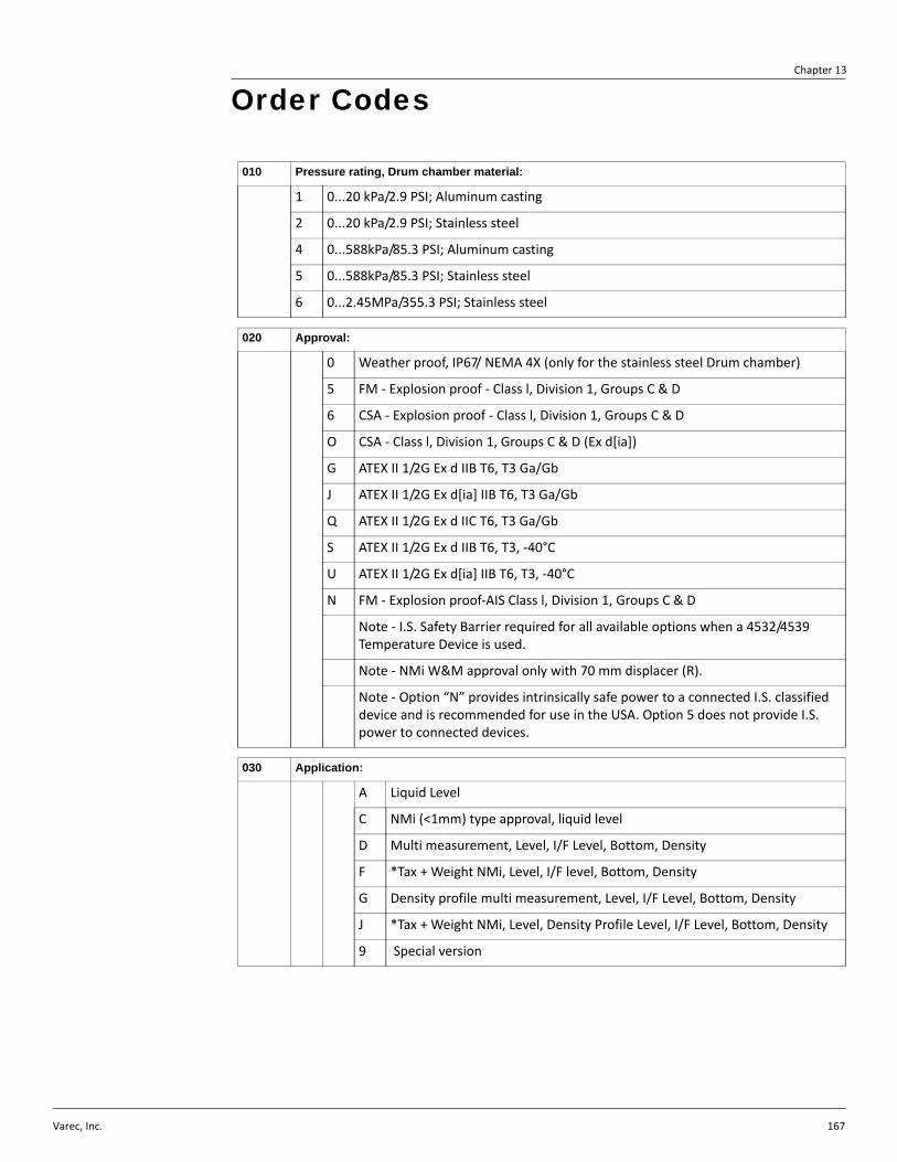
Varec, Inc. 167
Chapter 13
010 Pressure rating, Drum chamber material:
1 0...20 kPa/2.9 PSI; Aluminum casting
2 0...20 kPa/2.9 PSI; Stainless steel
4 0...588kPa/85.3 PSI; Aluminum casting
5 0...588kPa/85.3 PSI; Stainless steel
6 0...2.45MPa/355.3 PSI; Stainless steel
020 Approval:
0 Weather proof, IP67/ NEMA 4X (only for the stainless steel Drum chamber)
5 FM - Explosion proof - Class l, Division 1, Groups C & D
6 CSA - Explosion proof - Class l, Division 1, Groups C & D
O CSA - Class l, Division 1, Groups C & D (Ex d[ia])
G ATEX II 1/2G Ex d IIB T6, T3 Ga/Gb
J ATEX II 1/2G Ex d[ia] IIB T6, T3 Ga/Gb
Q ATEX II 1/2G Ex d IIC T6, T3 Ga/Gb
S ATEX II 1/2G Ex d IIB T6, T3, -40°C
U ATEX II 1/2G Ex d[ia] IIB T6, T3, -40°C
N FM - Explosion proof-AIS Class l, Division 1, Groups C & D
Note - I.S. Safety Barrier required for all available options when a 4532/4539 Temperature Device is used.
Note - NMi W&M approval only with 70 mm displacer (R).
Note - Option “N” provides intrinsically safe power to a connected I.S. classified device and is recommended for use in the USA. Option 5 does not provide I.S. power to connected devices.
030 Application:
A Liquid Level
C NMi (<1mm) type approval, liquid level
D Multi measurement, Level, I/F Level, Bottom, Density
F *Tax + Weight NMi, Level, I/F level, Bottom, Density
G Density profile multi measurement, Level, I/F Level, Bottom, Density
J *Tax + Weight NMi, Level, Density Profile Level, I/F Level, Bottom, Density
9 Special version
Order Codes
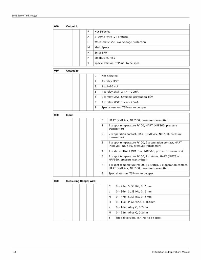
6005 Servo Tank Gauge
168 Installation and Operations Manual
040 Output 1:
F Not Selected
A 2-way 2-wire (V1 protocol)
L Whessmatic 550, overvoltage protection
M Mark Space
N Enraf BPM
P Modbus RS-485
9 Special version, TSP-no. to be spec.
050 Output 2:‘
0 Not Selected
1 4x relay SPST
2 2 x 4-20 mA
3 4 x relay SPST, 2 x 4 - 20mA
4 2 x relay SPST, Overspill prevention TÜV
5 4 x relay SPST, 1 x 4 - 20mA
9 Special version, TSP-no. to be spec.
060 Input:
0 HART (NMT5xx, NRF560, pressure transmitter)
1 1 x spot temperature Pt100, HART (NRF560, pressure transmitter)
2 2 x operation contact, HART (NMT5xx, NRF560, pressure transmitter)
3 1 x spot temperature Pt100, 2 x operation contact, HART (NMT5xx, NRF560, pressure transmitter)
4 1 x status, HART (NMT5xx, NRF560, pressure transmitter)
5 1 x spot temperature Pt100, 1 x status, HART (NMT5xx, NRF560, pressure transmitter)
6 1 x spot temperature Pt100, 1 x status, 2 x operation contact, HART (NMT5xx, NRF560, pressure transmitter)
9 Special version, TSP-no. to be spec.
070 Measuring Range; Wire:
C 0 - 28m; SUS316L, 0.15mm
L 0 - 36m; SUS316L, 0.15mm
N 0 - 47m; SUS316L, 0.15mm
H 0 - 16m; PFA>SUS316, 0.4mm
K 0 - 16m; Alloy C, 0.2mm
M 0 - 22m; Alloy C, 0.2mm
Y Special version, TSP-no. to be spec.

Chapter 13 - Order Codes
Varec, Inc. 169
080 Cable entry:
E 4 x thread G1/2
F 4 x thread G3/4
H 4 x thread NPT3/4
L 4 x thread M20
M 4 x thread M25
Y Special version, TSP-no. to be spec.
090 Process connection:
G 3" 150Ibs RF, flange JIS B2220
J 3" 300lbs RF, flange ANSI B16.5
W 4" 300lbs RF, flange ANSI B16.5
T 6" 150lbs RF, flange ANSI B16.5
L DN80 PN10 B1, flange EN1092-1 (DIN2527 B)
N DN80 PN25 B1, flange EN1092-1 (DIN2527 B)
Y Special version, TSP-no. to be spec.
100 Power supply:
3 85 - 264 VAC, 50/60 Hz
4 20 - 62 VDC, 20 - 55 VAC, 50/60 Hz
9 Special version, TSP-no. to be spec.
110 Displacer:
N Cylindrical 30 mm, SUS316
K Cylindrical 40 mm, SUS316
D Cylindrical 50 mm, SUS316
W Cylindrical 30 mm, PTFE
V Cylindrical 40 mm, PTFE
U Cylindrical 50 mm, PTFE
T Cylindrical 30 mm, Alloy C
B Conical 50 mm, PTFE
R Conical 70 mm, SU316
C Conical 110 mm, SU316
N6005- Product Designation

6005 Servo Tank Gauge
170 Installation and Operations Manual
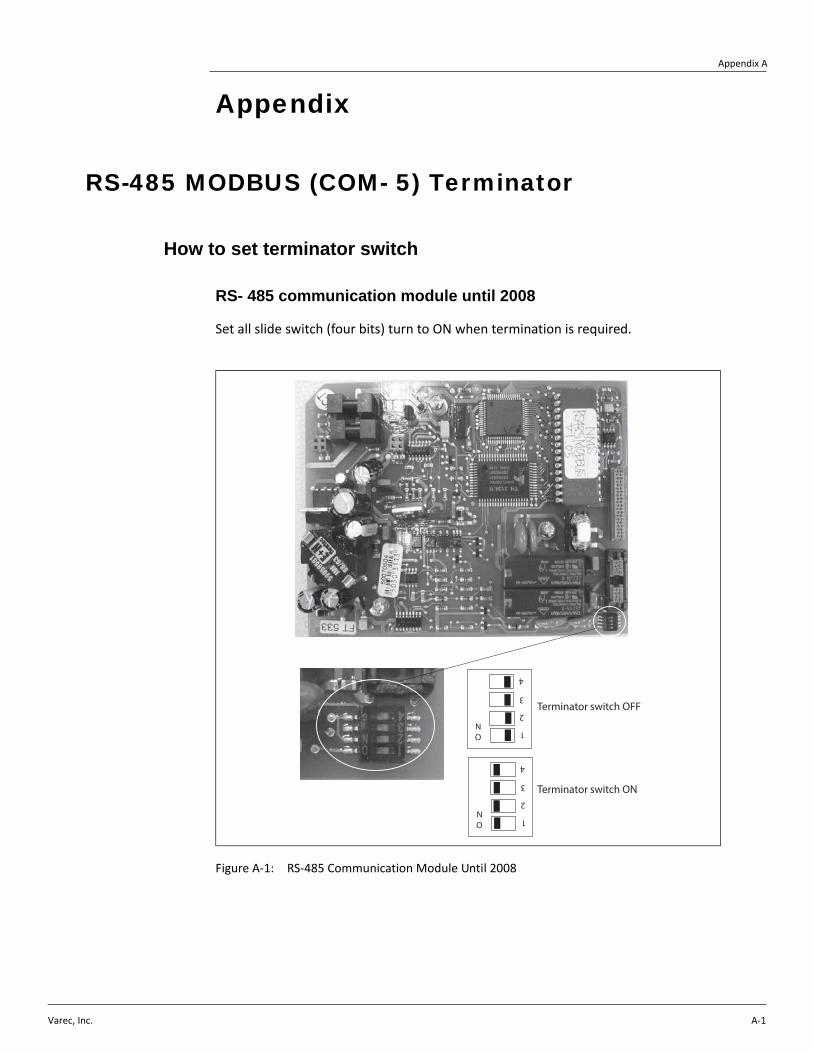
Varec, Inc. A-1
Appendix A
Appendix
RS-485 MODBUS (COM- 5) Terminator
How to set terminator switch
RS- 485 communication module until 2008
Set all slide switch (four bits) turn to ON when termination is required.
Figure A-1: RS-485 Communication Module Until 2008
1
2
3
4
ON
Terminator switch OFF
1
2
3
4
ON
Terminator switch ON
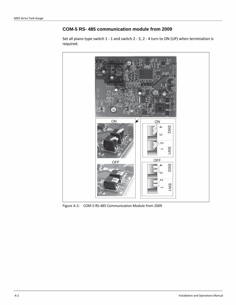
6005 Servo Tank Gauge
A-2 Installation and Operations Manual
COM-5 RS- 485 communication module from 2009
Set all piano type switch 1 - 1 and switch 2 - 3, 2 - 4 turn to ON (UP) when termination is required.
Figure A-2: COM-5 RS-485 Communication Module from 2009
OFF
ON
SW
2S
W1
43
21
SW
2S
W1
43
21
ON
OFF

Appendix A - Appendix
Varec, Inc. A-3
Changing Measurement Wire
Winding wire onto wire drum
1. Prepare a box with approx. 300mm(w) × 300mm(d) × 50mm(h) for wire storing.
2. Take out the measurement wire from the plastic bag.
3. Put the wire into the box without twisting.
4. Put one end of the wire into a hole on wire drum groove.
5. Fix the end of the wire by screw.
6. Sit down on a chair.
7. Grasp drum by left hand and hold wire by left thumb.
8. Hold wire by right thumb and index finger.
9. Make tension to secure the wire, so as not to come out of the groove.
10. Rotate the wire drum to wind the wire into groove with holding by left thumb.

6005 Servo Tank Gauge
A-4 Installation and Operations Manual
Figure A-3: Winding Wire Onto Wire Drum
Wire hole
HoleScrew
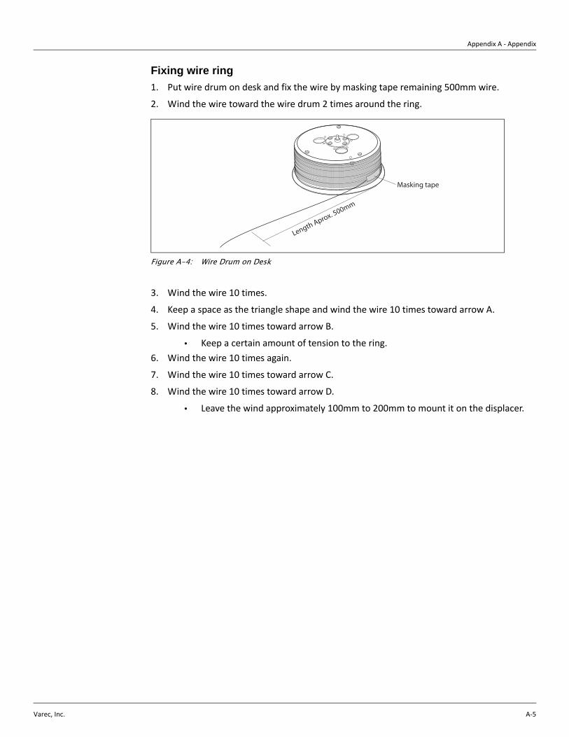
Appendix A - Appendix
Varec, Inc. A-5
Fixing wire ring
1. Put wire drum on desk and fix the wire by masking tape remaining 500mm wire.
2. Wind the wire toward the wire drum 2 times around the ring.
Figure A-4: Wire Drum on Desk
3. Wind the wire 10 times.
4. Keep a space as the triangle shape and wind the wire 10 times toward arrow A.
5. Wind the wire 10 times toward arrow B.
• Keep a certain amount of tension to the ring.6. Wind the wire 10 times again.
7. Wind the wire 10 times toward arrow C.
8. Wind the wire 10 times toward arrow D.
• Leave the wind approximately 100mm to 200mm to mount it on the displacer.
Masking tape
Length Aprox. 500mm
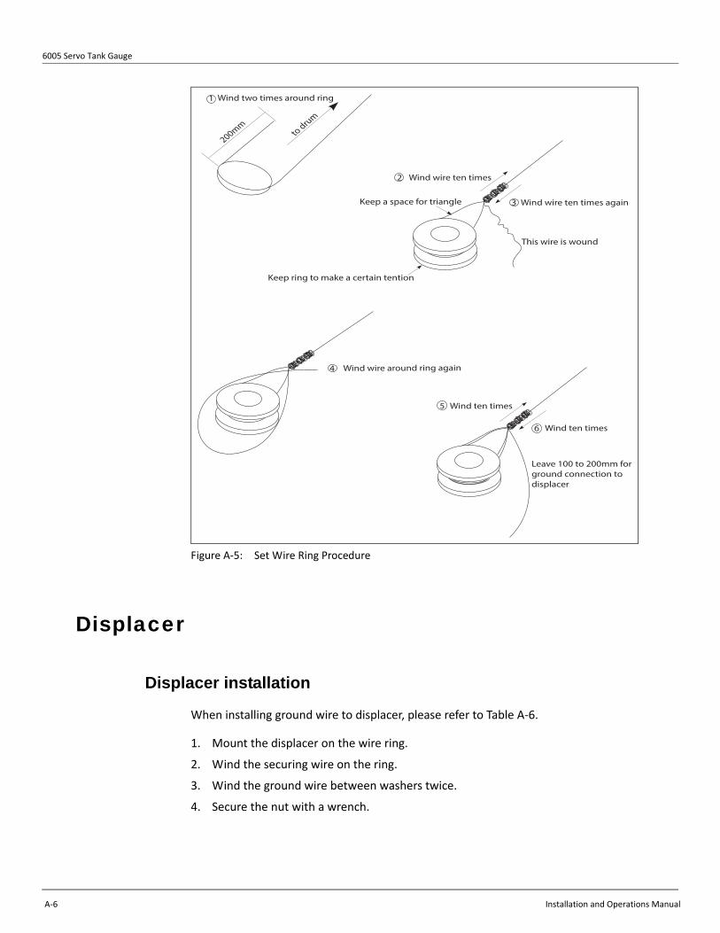
6005 Servo Tank Gauge
A-6 Installation and Operations Manual
Figure A-5: Set Wire Ring Procedure
Displacer
Displacer installation
When installing ground wire to displacer, please refer to Table A-6.
1. Mount the displacer on the wire ring.
2. Wind the securing wire on the ring.
3. Wind the ground wire between washers twice.
4. Secure the nut with a wrench.
Wind wire ten times2
3 Wind wire ten times again
This wire is wound
Keep ring to make a certain tention
Keep a space for triangle
Wind wire around ring again
to drum
200mm
1 Wind two times around ring
5 Wind ten times
6 Wind ten times
Leave 100 to 200mm forground connection to displacer
4

Appendix A - Appendix
Varec, Inc. A-7
Figure A-6: Displacer Installation
PTFE Displacer Installation
1. Remove the screw using a flat-head screw driver.
2. Mount the displacer on the teflon-ring.
Step 1
Ground Wire
Displacer Ground Wire
Washer
Wire Ring
Nut
Securing WireDisplacer
Step 2
Step 3
Wrench
Step 4

6005 Servo Tank Gauge
A-8 Installation and Operations Manual
3. PTFE Wire: Install the ground wire of the displacer from the wire insertion slot until the ground wire touches the wall of the screw hole.
4. SUS Wire: Install the ground wire of the displacer from the wire insertion slot until the ground wire touches the wall of the screw hole. Then install the ground wire 10 mm farther.
5. Tighten the screw.
• Hold the ground wire with finger tip so that the wire does not come out from the slot.6. Lift the displacer using the flat-head screw driver and confirm that the ground wire does
not come out from the slot.
Step 1 Step 2
Step 3: PTFE Wire Step 4: SUS Wire
Step 5 Step 6
Finger Tip
Teflon-ring
Insertion Hole for WirePTFE Screw (M5)
Displacer
Screw Hole Ground Wire for Displacer

Appendix A - Appendix
Varec, Inc. A-9
Displacers
Actual draft position may change slightly with tank parameters.
Figure A-7: Displacers
165.
5 m
m
121m
m3.
6mmØ 30 mm
Draft point
63.8
mm
WeightVolumeBalance volumeDraft point
261g85cm3
41.3cm3
63.8mm
140m
mØ 30 mm
Draft point
172m
m
WeightVolumeBalance volumeDraft point
240g108cm3
53.7cm3
79.5mm
9.5m
m
79.5
mm
9.5m
m
Ø30mm SUS Cylindrical Ø30mm PTFE Cylindrical
165.
5mm
121m
m3.
6mm
Draft point
64.1
mm
WeightVolumeBalance volumeDraft point
254g152cm3
71.1cm3
64.1mm
Ø 40mm
122m
m
87m
m11
mm
Draft point
54.5
mm
WeightVolumeBalance volumeDraft point
280g126cm3
62.6cm3
54.5mm
Ø 40mm
11m
m
Ø 11mm
Ø40mm SUS Cylindrical Ø40mm PTFE Cylindrical
Ø 11mm

6005 Servo Tank Gauge
A-10 Installation and Operations Manual
Figure A-8: Displacers, continued
128.
8mm
85m
m2.
5mm
Draft point
45.0
mm
WeightVolumeBalance volumeDraft point
253g138cm3
70.8cm3
45.0mm
Ø 50.8mm
116.
6mm
85m
m2.
5mm
Draft point
45.0
mm
WeightVolumeBalance volumeDraft point
250g138cm3
70.8cm3
45.0mm
Ø 50.8mm89
mm
53m
m11
.5m
m
Draft point
38m
m
WeightVolumeBalance volumeDraft point
290g130cm3
64.7cm3
38.0mm
Ø 50.8mm
11.5
mm
Ø50mm AlloyC CylindricalØ50mm SUS Cylindrical
Ø50mm PTFE Cylindrical
93m
m
60m
m5m
m
Draft point
35m
m
WeightVolumeBalance volumeDraft point
290g131cm3
62.2cm3
35.0mm
Ø 50mm
16m
m12
mm
Ø50mm PTFE Conical
Ø 11mmØ 11mm

Appendix A - Appendix
Varec, Inc. A-11
Figure A-9: Displacers, continued
90m
m
Draft point
WeightVolumeBalance volumeDraft point
245g122cm3
52.7cm3
16.9mm
Ø 70mm
47.6
mm
5.4m
m
16.9
mm
67m
m
26m
m2m
mØ 110 mm
Draft point10.0
mm
WeightVolumeBalance volumeDraft point
223g136cm3
36.3cm3
10.0mm
Ø110mm SUS Conical PTB-W&M
Ø70mm SUS Conical NMi-W&M

6005 Servo Tank Gauge
A-12 Installation and Operations Manual
Varec, Inc.
Servo Tank Gauge Index
Index
Numerics453x Temperature Device Connections Settings . . 674560 Servo Monitor Connections Settings . . . . . 686005 Product Dimensions . . . . . . . . . . . . . . . . . . 9
AAccess Code . . . . . . . . . . . . . . . . . . . . . . . . . . . 55Access Code, settting . . . . . . . . . . . . . . . . . . . . 56Alarm . . . . . . . . . . . . . . . . . . . . . . . . . . . . . . . . . 66Alarm Messages . . . . . . . . . . . . . . . . . . . . . . . 113All-in-One . . . . . . . . . . . . . . . . . . . . . . . . . . . . . . 30Analog Output (GVF250 to 256) . . . . . . . . . . . . 66asymmetric pipe . . . . . . . . . . . . . . . . . . . . . . . . . 17
BBalance . . . . . . . . . . . . . . . . . . . . . . . . . . . . . . . 54balance volume . . . . . . . . . . . . . . . . . . . . . . . . 103
CCable Connection . . . . . . . . . . . . . . . . . . . . . . . . 30Cable Gland . . . . . . . . . . . . . . . . . . . . . . . . . . . . 44Calculation of Level and Densities . . . . . . . . . . . 60calibration . . . . . . . . . . . . . . . . . . . . . . . . . . . . . 115CE mark . . . . . . . . . . . . . . . . . . . . . . . . . . . . . . . 14Certificates and Approvals . . . . . . . . . . . . . . . . . 14Changing Measurement Wire . . . . . . . . . . . . . . . 3Cleaning the Exterior . . . . . . . . . . . . . . . . . . . . . 91Clock . . . . . . . . . . . . . . . . . . . . . . . . . . . . . . . . . 63Commissioning safety . . . . . . . . . . . . . . . . . . . . . 1Communications Address (GVH285) . . . . . . . . . 64Connections, external . . . . . . . . . . . . . . . . . . . . . 2Contact Relay Alarm (GVH240 to 247) . . . . . . . 66
Ddeclaration of conformity . . . . . . . . . . . . . . . . . . 14Densities . . . . . . . . . . . . . . . . . . . . . . . . . . . . . . 61Density . . . . . . . . . . . . . . . . . . . . . . . . . . . . . . . 117Density Measurement . . . . . . . . . . . . . . . . . . . . 80Density Profile Measurement . . . . . . . . . . . 80, 82Density Values (GVH005 to 007) . . . . . . . . . . . . 63Designated use . . . . . . . . . . . . . . . . . . . . . . . . . . 1Diagnosis . . . . . . . . . . . . . . . . . . . . . . . . . . . . . . 93Diagnosis and Troubleshooting . . . . . . . . . . . . . 93Diagnostic Code . . . . . . . . . . . . . . . . . . . . . . . . . 93diagnostic history . . . . . . . . . . . . . . . . . . . . . . . . 93Diagnostics and Troubleshooting Flowcharts . . . 97Dip Point Offset . . . . . . . . . . . . . . . . . . . . . . . . . 63Displacer
Initial Weight Calibration . . . . . . . . . . . . . . . 115Shape, Diameter, and Material . . . . . . . . . . 111Types . . . . . . . . . . . . . . . . . . . . . . . . . . . . . . 10Weight Calibration . . . . . . . . . . . . . . . . . . . . 117
Displacer Installation . . . . . . . . . . . . . . . . . . . . . . 6
Displacer Operation . . . . . . . . . . . . . . . . . . . . . . 59displacer status . . . . . . . . . . . . . . . . . . . . . . . . . 53DISPLACER VOLUME . . . . . . . . . . . . . . . . . . 103Displacer, 50 mm . . . . . . . . . . . . . . . . . . . . . . . . 33Display . . . . . . . . . . . . . . . . . . . . . . . . . . . . . . . 112Draft . . . . . . . . . . . . . . . . . . . . . . . . . . . . . . . . . . 61Dynamic Matrix . . . . . . . . . . . . . . . . . . . . . . . . . 67
EElectrostatic Charge . . . . . . . . . . . . . . . . . . . . . . 30ENRAF BPM . . . . . . . . . . . . . . . . . . . . . . . . . . . 44Error and Status Messages . . . . . . . . . . . . . . . . 94Ex approval . . . . . . . . . . . . . . . . . . . . . . . . . . . 165Ex d HART Input . . . . . . . . . . . . . . . . . . . . . . . . 45Ex d IIB, Output 1 V1, RS485, HART, Enraf, BPM, Modbus . . . . . . . . . . . . . . . . . . . . . . . . . . . . . . . 38Ex d PT100 Spot Temperature Input . . . . . . . . . 45Ex d, Output1 Mark/Space protocol . . . . . . . . . . 42Ex ia HART input . . . . . . . . . . . . . . . . . . . . . . . . 46Ex ia Pt100 Sport Temperature Input . . . . . . . . . 47explosion-proof type . . . . . . . . . . . . . . . . . . . . . . . 2External connections . . . . . . . . . . . . . . . . . . . . . . 2
FFixed Roof Tank with Stilling Well . . . . . . . . . . . 23Flange . . . . . . . . . . . . . . . . . . . . . . . . . . . . . . . . 28Flaoting Roof Tank Installation . . . . . . . . . . . . . . 25Floating roof tank . . . . . . . . . . . . . . . . . . . . . . . . 15
GGauge Software . . . . . . . . . . . . . . . . . . . . . . . . 108Gauge status . . . . . . . . . . . . . . . . . . . . . . . . . . . 53Grounding . . . . . . . . . . . . . . . . . . . . . . . . . . . . . . 3
HHall Sensors . . . . . . . . . . . . . . . . . . . . . . . . . . . 113Hazardous area
use of instrument . . . . . . . . . . . . . . . . . . . . . . 3hazardous area operational safety . . . . . . . . . . . . 2Hazardous area use . . . . . . . . . . . . . . . . . . . . . . . 1Hazardous Substance Datasheet . . . . . . . . . . 108High Pressure Tank . . . . . . . . . . . . . . . . . . . . . . 24Home position . . . . . . . . . . . . . . . . . . . . . . . . . . 53
IEx d . . . . . . . . . . . . . . . . . . . . . . . . . . . . . . 39, 43Identification . . . . . . . . . . . . . . . . . . . . . . . . . . . . 11IIB, Output 1 V1, RS485, HART, Enraf, BPM, Mod-bus . . . . . . . . . . . . . . . . . . . . . . . . . . . . . . . . . . . 39Initial setting . . . . . . . . . . . . . . . . . . . . . . . . . . . . 63Input and Output specifications . . . . . . . . . . . . . 44Installation . . . . . . . . . . . . . . . . . . . . . . . . . . . . . . 7Installation of Wire Drum and Displacer . . . . . . . 30Installation safety . . . . . . . . . . . . . . . . . . . . . . . . . 1Installation with Displacer shipped separately . . 32

Index 6000
Installation and Operations Manual
Intelligent Function . . . . . . . . . . . . . . . . . . . . . 104Interface Measurement . . . . . . . . . . . . . . . 82, 89
JJumper . . . . . . . . . . . . . . . . . . . . . . . . . . . . . . . 73
LLCD . . . . . . . . . . . . . . . . . . . . . . . . . . . . . . . . . . 96Liquid Level Calibration . . . . . . . . . . . . . . . . . . . 69
Closed Tanks . . . . . . . . . . . . . . . . . . . . . . . . 70Open tanks . . . . . . . . . . . . . . . . . . . . . . . . . . 69
MMaintenance . . . . . . . . . . . . . . . . . . . . . . . . . . . 91Mark/Space . . . . . . . . . . . . . . . . . . . . . . . . . . . . 42matrix group . . . . . . . . . . . . . . . . . . . . . . . . . . . 52Measuring Wire . . . . . . . . . . . . . . . . . . . . . . . . 111
Material . . . . . . . . . . . . . . . . . . . . . . . . . . . 111Mounting Preparations . . . . . . . . . . . . . . . 16, 28Mounting with a Stilling Well . . . . . . . . . . . . . . . 17Mounting with Guide Wire . . . . . . . . . . . . . . . . . 20Mounting without Guide System . . . . . . . . . . . . 16
Nnameplate . . . . . . . . . . . . . . . . . . . . . . . . . . . . . 11NRF . . . . . . . . . . . . . . . . . . . . . . . . . . . . . . . . . . 68
OOperating Element . . . . . . . . . . . . . . . . . . . . . . 49Operating Elements functions . . . . . . . . . . . . . . 50Operation . . . . . . . . . . . . . . . . . . . . . . . . . . . . . 49Operation Commands . . . . . . . . . . . . . . . . . . . . 57Operation safety . . . . . . . . . . . . . . . . . . . . . . . . . 1Operation status, new . . . . . . . . . . . . . . . . . . . . 57Operational safety
hazardous areas . . . . . . . . . . . . . . . . . . . . . . 2Order Codes . . . . . . . . . . . . . . . . . . . . . . . . . . 167
PParts
Disposal . . . . . . . . . . . . . . . . . . . . . . . . . . . 108Return . . . . . . . . . . . . . . . . . . . . . . . . . . . . 108
Pipe . . . . . . . . . . . . . . . . . . . . . . . . . . . . . . . . . . 17Pipe diameter . . . . . . . . . . . . . . . . . . . . . . . . . . 17power consumption . . . . . . . . . . . . . . . . . . . . . . 37power source
product requirements . . . . . . . . . . . . . . . . . . . 1power supply cable . . . . . . . . . . . . . . . . . . . . . . . 2Proactive Safety Function (GVH157/158/159) . 65product requrements
power source . . . . . . . . . . . . . . . . . . . . . . . . . 1Programming Matrix . . . . . . . . . . . . . . . . . 49, 119
RRackbus RS-485 . . . . . . . . . . . . . . . . . . . . . . . . 72Relay Logic . . . . . . . . . . . . . . . . . . . . . . . . . . . . 79Remote Communication . . . . . . . . . . . . . . . . . . 72
. . . . . . . . . . . . . . . . . . . . . . . . . . . . . . . . . . . 78
Analog Output . . . . . . . . . . . . . . . . . . . . . . . 77Enraf BiPhase . . . . . . . . . . . . . . . . . . . . . . . 76Mark/Space . . . . . . . . . . . . . . . . . . . . . . . . . 73Whessoe Matic 550 (WM550) . . . . . . . . . . . 73
Repairs . . . . . . . . . . . . . . . . . . . . . . . . . . . . . . . 91Repairs to Ex Approved Devices . . . . . . . . . . . 91Replacement . . . . . . . . . . . . . . . . . . . . . . . . . . . 92Replacing Seals . . . . . . . . . . . . . . . . . . . . . . . . 91RS-485 MODBUS (COM- 5) Terminator . . . . . . . 1
SSafety conventions and symbols . . . . . . . . . . . . . 4Safety Level Default . . . . . . . . . . . . . . . . . . . . . 65Scope of Delivery . . . . . . . . . . . . . . . . . . . . . . . 13Sealing the 6005 STG . . . . . . . . . . . . . . . . . . . . 90Software history . . . . . . . . . . . . . . . . . . . . . . . 108Spare Parts . . . . . . . . . . . . . . . . . . . . . . . . . . . 104Spot Density Measurement . . . . . . . . . . . . . . . . 80Static Matrix . . . . . . . . . . . . . . . . . . . . . . . . . . . . 56Surface and Interface Levels . . . . . . . . . . . . . . 60
TTank Bottom Level . . . . . . . . . . . . . . . . . . . . . . . 61Tank Height . . . . . . . . . . . . . . . . . . . . . . . . . . . . 63Technical Data . . . . . . . . . . . . . . . . . . . . . . . . . 165Temperature Input System . . . . . . . . . . . . . . . . 45Tools . . . . . . . . . . . . . . . . . . . . . . . . . . . . . . . . . . 9Touch Control . . . . . . . . . . . . . . . . . . . . . . . . . . 49
UUpper/Lower Stop (GVH161/162) . . . . . . . . . . . 64
VVarec Address . . . . . . . . . . . . . . . . . . . . . . . . . 109
WWhessoe Matic 550 . . . . . . . . . . . . . . . . . . . . . . 40Whessoe Matic 550 protocol non-IS . . . . . . . . . 40Whessoe Matic 550 protocol with IS . . . . . . . . . 41Wiring . . . . . . . . . . . . . . . . . . . . . . . . . . . . . . . . 37Wiring connections . . . . . . . . . . . . . . . . . . . . . . 37
ZZ PHASE . . . . . . . . . . . . . . . . . . . . . . . . . . . . . . 95


Varec, Inc. • 5834 Peachtree Corners East, Peachtree Corners (Atlanta), GA 30092 USATel: +1 (770) 447-9202 • Fax: +1 (770) 662-8939
www.varec.com
© 2015 Varec, Inc. All Rights Reserved. This document is for information purposes only. Varec, Inc. makes no warranties, express or implied, in this summary. The names of actual companies and products mentioned herein may be the trademarks of their respective owners.
Document CodeIOM007NVAE2415