600 S 162 - 54 - PriceWeberimgserver.cms2005.com/imgServer/9330191/SSS_Red_CatalogLR_3.09… · or...
36
-
Upload
truongdieu -
Category
Documents
-
view
216 -
download
0
Transcript of 600 S 162 - 54 - PriceWeberimgserver.cms2005.com/imgServer/9330191/SSS_Red_CatalogLR_3.09… · or...
Steel Structural Systems (TRI-S) was founded in 2004 to meet the service needs of a growing industry. The company is a world-class manufacturer of light gauge steel framing components for the commercial and residential markets. By utilizing its vast experience and relationships within the steel industry, TRI-S is able to provide competitively priced, high quality products to an extensive network of distributors, dealers, and value added centers. Its manufacturing operation allows for the flexibility to efficiently accommodate both large and small orders as well as custom length components.
General Information and Product SpecificationsThis manual describes the stud and track components manufac-tured by TRI-S for curtain wall and load bearing construction. The enclosed tables provide necessary information regarding the physical and structural properties of section members in vari-ous load applications. The data contained in this publication is intended as a general guide only. It is not intended to replace the design, specifications and drawings of a professional architect or engineer experienced with cold formed light gauge steel design. TRI-S assumes no liability for failure resulting from the use or misapplication of the information contained herein.
The types of TRI-S products used for particular applications depends on thickness, coating type, yield strength, section properties, and the specifications and standards established by ASTM International, the American Iron and Steel Institute (AISI) and code authorities as detailed by the following.
ASTM C 955 Standard Specification for Load Bearing (Transverse and Axial) Steel Studs, Runners (Tracks), and Bracing and Bridging for Screw Application of Gypsum Panel Products and Metal Plaster Bases
ASTM C 1003 (ST33L, ST33H, ST50L, ST50H) Standard Specification for Steel Sheet, Carbon, Metallic and Nonmetallic -Coated for Cold-Formed Framing Members
ASTM A653/653A Standard Specification for Steel Sheet, Zinc-Coated (Galvanized) or Zinc-Iron Alloy-Coated (Galvannealed) by the Hot-Dipped Process
Where ‘NASPEC’ is referenced in this publication, it is the “North American Specification for the Design of Cold-Formed Steel Structural Members”, 2001 edition, including the 2004 Supplement, US provisions. All TRI-S Physical Properties and Tables have been calculated by Devco Engineering, Corvallis, OR in accordance with NASPEC. The strength increase from cold work of forming has been incorporated for flexural strength per NASPEC A7.2. The Yield Point (33 or 50 ksi) used to calculate the tabulated values are shown in each table. The Moment of Inertia for Deflection is calculated at a stress which results in an effective section modulus so the stress multiplied by that section modulus is equal to the allowable moment. For the steels that have 33 and 50 ksi listings, if the design is based upon 50 ksi material, the 50 ksi steel needs to be specified by the purchaser.
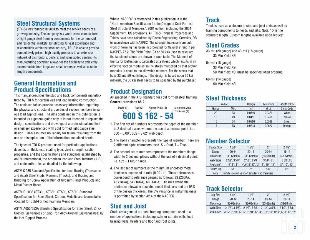
Product DesignationAs specified in the AISI standard for cold formed steel framing General provisions A5.2.
1. The first set of numbers represents the depth of the member to 2 decimal places without the use of a decimal point. i.e.: 600 = 6.00”, 362 = 3.62” web depth.
2. The alpha character represents the type of member. There are 2 different alpha characters used. S = Stud, T = Track.
3. The second set of numbers represents the members flange width to 2 decimal places without the use of a decimal point. i.e. 162 = 1.625” flange.
4. The last set of numbers is the minimum uncoated metal thickness expressed in mils (0.001 in). These thicknesses correspond to reference gauges as follows: 33 (20GA), 43 (18GA), 54 (16GA), 68 (14GA). The mils define the minimum allowable uncoated metal thickness and are 95% of the design thickness. The 5% variance in metal thickness is permitted by section A2.4 of the NASPEC.
Stud and JoistStuds are a general purpose framing component used in a number of applications including exterior curtain walls, load bearing walls, headers and floor and roof joists.
2
600 S 162 - 54Depth (1) Type (2) Flange Width (3) Minimum Metal Thickness (4)
Leg Size 1 1/4” 1 1/2” 2” 2 1/2” Gauge 20-14 20-14 20-14 20-14 Thickness (33-68mils) (33-68mils) (33-68mils) (33-68mils) Web Sizes 2 1/2”, 3 5/8”, 2 1/2”, 3 5/8, 2 1/2”, 3 5/8, 2 1/2”, 3 5/8, Available* 4”, 6”, 8”, 10”, 12” 6”, 8”, 10”, 12” 4”, 6”, 8”, 10”, 12” 4”, 6”, 8”, 10”, 12”
Product Design Minimum ASTM C955 Gauge Mils (in.) (in.) Color Code 20 33 0.0346 0.0329 White 18 43 0.0451 0.0428 Yellow 16 54 0.0566 0.0538 Green 14 68 0.0713 0.0677 Orange
Member Selector
Track Selector
Flange Size 1 3/8” 1 5/8” 2” 2 1/2” Gauge 20-14 20-14 20-14 18-14 Thickness (33-68mils) (33-68mils) (33-68mils) (43-68mils) Web Sizes 2 1/2”, 3 5/8”, 2 1/2”, 3 5/8, 3 5/8”, 6”, 3 5/8”, 6”, Available* 4”, 6”, 8” 4”, 6”, 8”, 10”, 12” 8”, 10”, 12” 8”, 10”, 12” Return Lip 3/8” 1/2” 5/8” 5/8” Note: *Punch size will vary on smaller web members
Steel Thickness
TrackTrack is used as a closure to stud and joist ends as well as framing components to heads and sills. Note: 10’ is the standard length. Custom lengths available upon request.
Steel Grades33-mil (20 gauge) and 43-mil (18 gauge) 33 Min Yield KSI
54-mil (16 gauge) 33 Min Yield KSI 50 Min Yield KSI must be specified when ordering
68-mil (14 gauge) 50 Min Yield KSI
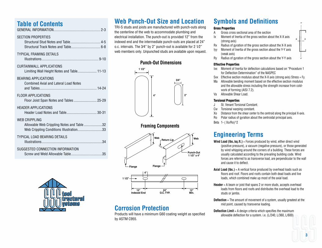
Table of ContentsGENERAL INFORMATION ................................................... 2-3
SECTION PROPERTIES Structural Stud Notes and Table ................................. 4-5 Structural Track Notes and Table ................................ 6-8
TYPICAL FRAMING DETAILS Illustrations .............................................................. 9-10
CURTAINWALL APPLICATIONS Limiting Wall Height Notes and Table ..................... 11-13
BEARING APPLICATIONS Combined Axial and Lateral Load Notes and Tables .............................................................. 14-24
FLOOR APPLICATIONS Floor Joist Span Notes and Tables ......................... 25-29
HEADER APPLICATIONS Header Load Notes and Table ................................. 30-31
WEB CRIPPLING Allowable Web Crippling Notes and Table ....................32 Web Crippling Conditions Illustration...........................33
TYPICAL LOAD BEARING DETAILS Illustrations ..................................................................34
SUGGESTED CONNECTION INFORMATION Screw and Weld Allowable Table ..................................35
Symbols and DefinitionsGross PropertiesA Gross cross sectional area of the sectionIx Moment of Inertia of the gross section about the X-X axis (strong axis)Rx Radius of gyration of the gross section about the X-X axisIyy Moment of Inertia of the gross section about the Y-Y axis (weak axis)Ry Radius of gyration of the gross section about the Y-Y axis
Effective PropertiesIxx Moment of Inertia for deflection calculations based on “Procedure 1 for Deflection Determination” of the NASPECSxx Effective section modulus about the X-X axis (strong axis) Stress = Fy.Ma Allowable bending moment based on the effective section modulus and the allowable stress including the strength increase from cold- work of forming (AISI 7.2).Va Allowable Shear Load.
Torsional PropertiesJ St. Venant Torsional Constant.Cw Torsional warping constant.Xo Distance from the shear center to the centroid along the principal X-axis.Ro Polar radius of gyration about the centroidal principal axis.Beta 1- ( Xo/Ro)^2
Engineering TermsWind Load (lbs./sq.ft.) = Forces produced by wind, either direct wind (positive pressure), a vacuum (negative pressure), or those generated by wind whipping around the corners of a building. These forces are usually calculated according to the prevailing building code. Wind forces are referred to as transverse load, are perpendicular to the wall and cause it to deflect.
Axial Load (lbs.) = A vertical force produced by overhead loads such as floors and roof. Floors and roofs contain both dead loads and live loads, which combined make up most of the axial load.
Header = A beam or joist that spans 2 or more studs, accepts overhead loads from floors and roofs and distributes the overhead load to the studs or jambs.
Deflection = The amount of movement of a system, usually greatest at the mid point, caused by transverse loading.
Deflection Limit = A design criteria which specifies the maximum allowable deflection for a system. i.e. (L/240, L/360, L/600)
3
Web Punch-Out Size and LocationTRI-S studs and joists are manufactured with punch-outs along the centerline of the web to accommodate plumbing and electrical installation. The punch-out is provided 12” from the indexed end and the intermediate punch-outs are placed at 24” o.c. intervals. The 3⁄4” by 2” punch-out is available for 2 1⁄2” web members only. Unpunched studs are available upon request.
Framing Components
Flange
Web WebReturn Lip
Flange
Punch-Out1 1/2" x 4"
4"
12"Indexed End
24"O.C. TYP.
12"Min.
1 1/2"
Punch-Out Dimensions1 1/2"
4"
3/4"
2"
Corrosion ProtectionProducts will have a minimum G60 coating weight as specified by ASTM C955.
Section Properties
4
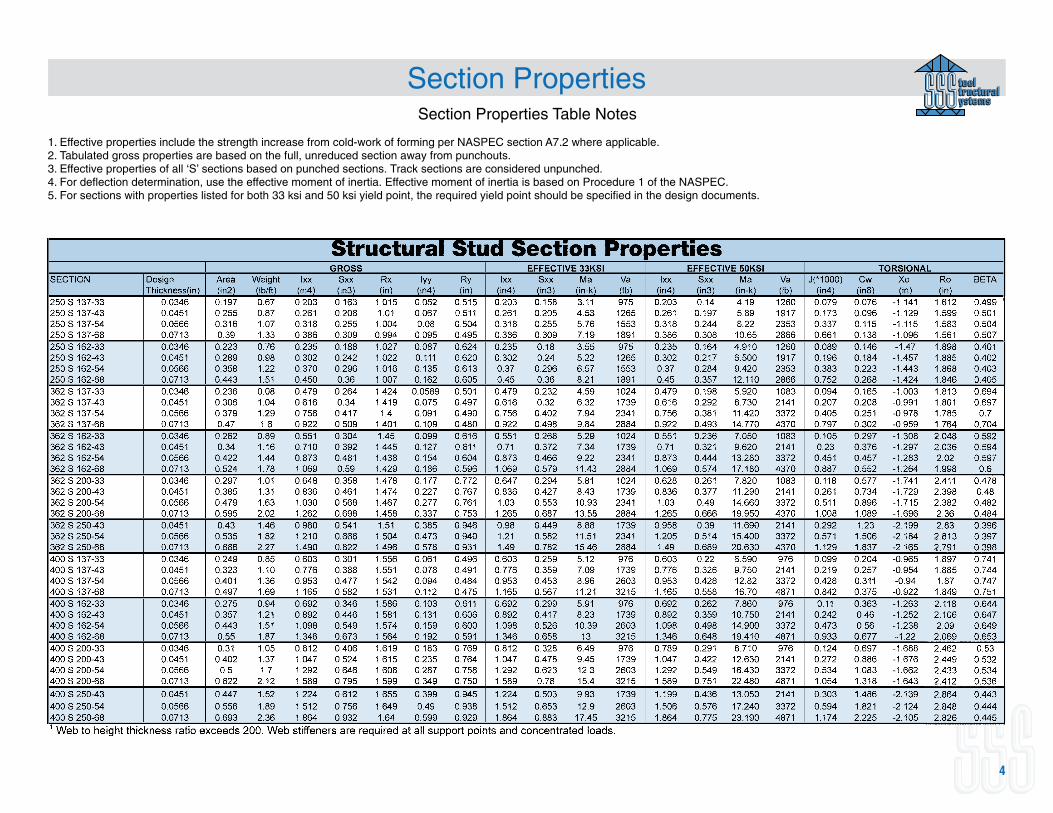
Section Properties Table Notes
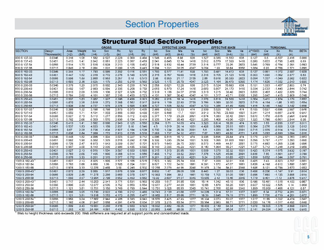
1. Effective properties include the strength increase from cold-work of forming per NASPEC section A7.2 where applicable.2. Tabulated gross properties are based on the full, unreduced section away from punchouts.3. Effective properties of all ‘S’ sections based on punched sections. Track sections are considered unpunched.4. For deflection determination, use the effective moment of inertia. Effective moment of inertia is based on Procedure 1 of the NASPEC.5. For sections with properties listed for both 33 ksi and 50 ksi yield point, the required yield point should be specified in the design documents.
Section Properties
5
Section Properties
6
Section Properties Table Notes
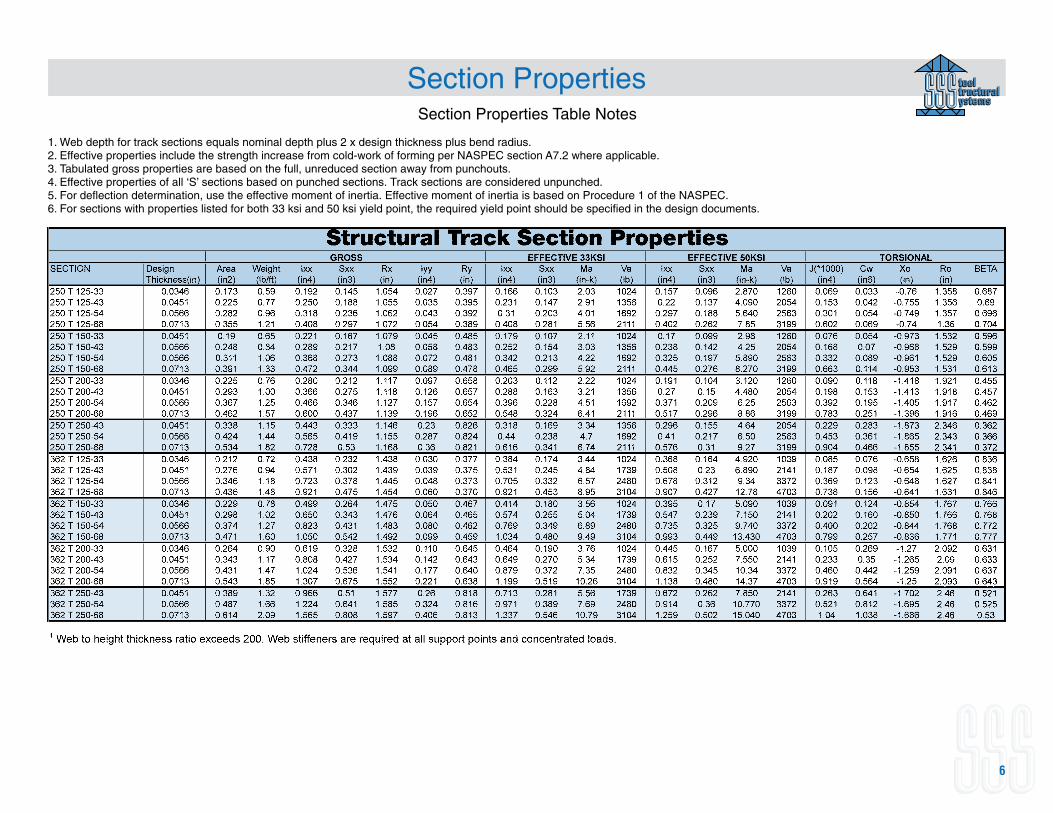
1. Web depth for track sections equals nominal depth plus 2 x design thickness plus bend radius.2. Effective properties include the strength increase from cold-work of forming per NASPEC section A7.2 where applicable.3. Tabulated gross properties are based on the full, unreduced section away from punchouts.4. Effective properties of all ‘S’ sections based on punched sections. Track sections are considered unpunched.5. For deflection determination, use the effective moment of inertia. Effective moment of inertia is based on Procedure 1 of the NASPEC.6. For sections with properties listed for both 33 ksi and 50 ksi yield point, the required yield point should be specified in the design documents.
Section Properties
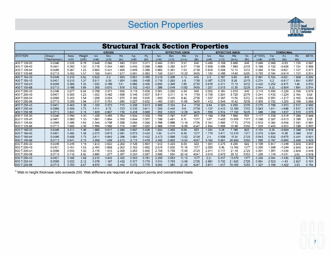
7
Section Properties
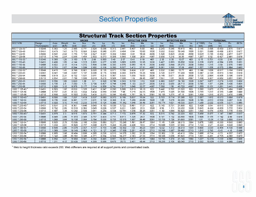
8
9
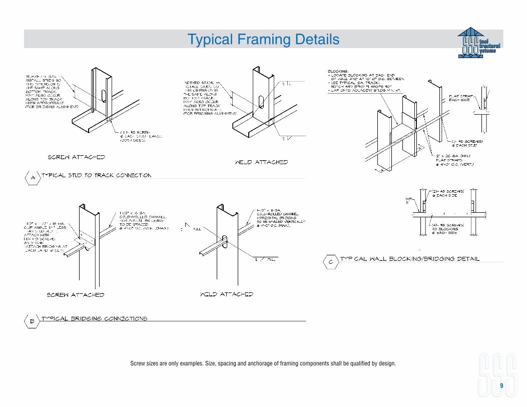
Typical Framing Details
Screw sizes are only examples. Size, spacing and anchorage of framing components shall be qualified by design.
10
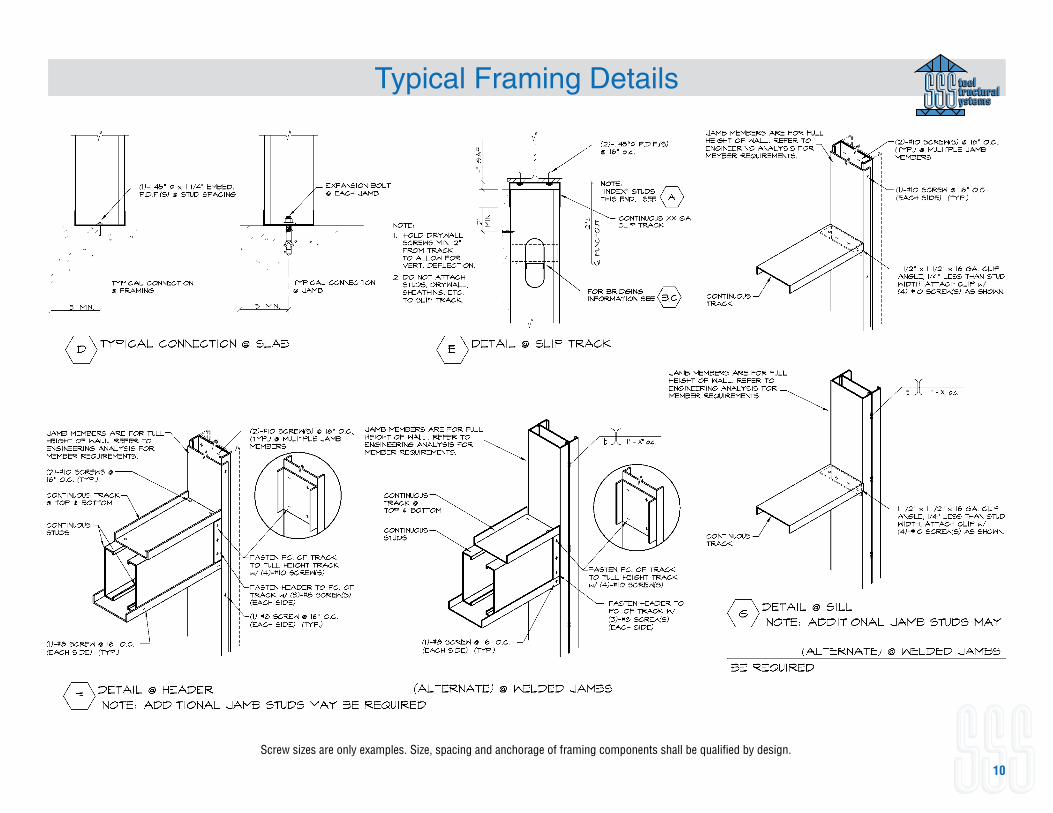
Typical Framing Details
Screw sizes are only examples. Size, spacing and anchorage of framing components shall be qualified by design.
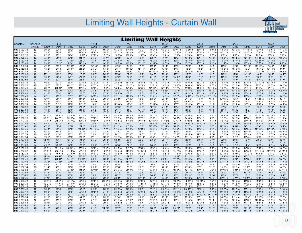
Limiting Wall Heights - Curtain Wall
11
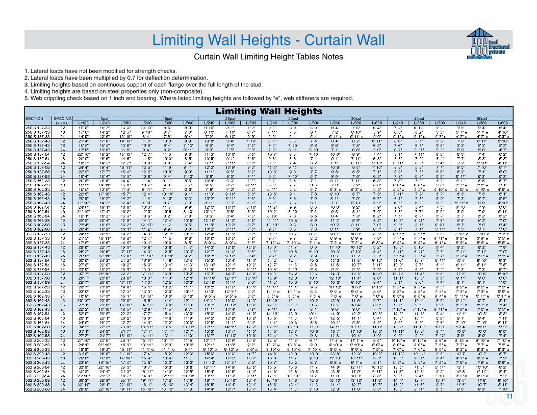
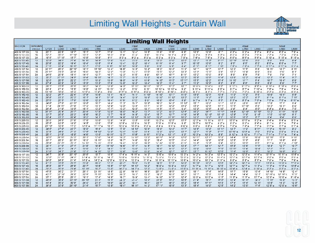
Curtain Wall Limiting Height Tables Notes
1. Lateral loads have not been modified for strength checks.2. Lateral loads have been multiplied by 0.7 for deflection determination.3. Limiting heights based on continuous support of each flange over the full length of the stud.4. Limiting heights are based on steel properties only (non-composite).5. Web crippling check based on 1 inch end bearing. Where listed limiting heights are followed by “e”, web stiffeners are required.
12
Limiting Wall Heights - Curtain Wall
13
Limiting Wall Heights - Curtain Wall
14
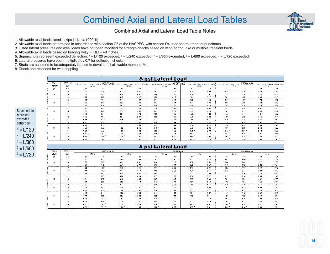
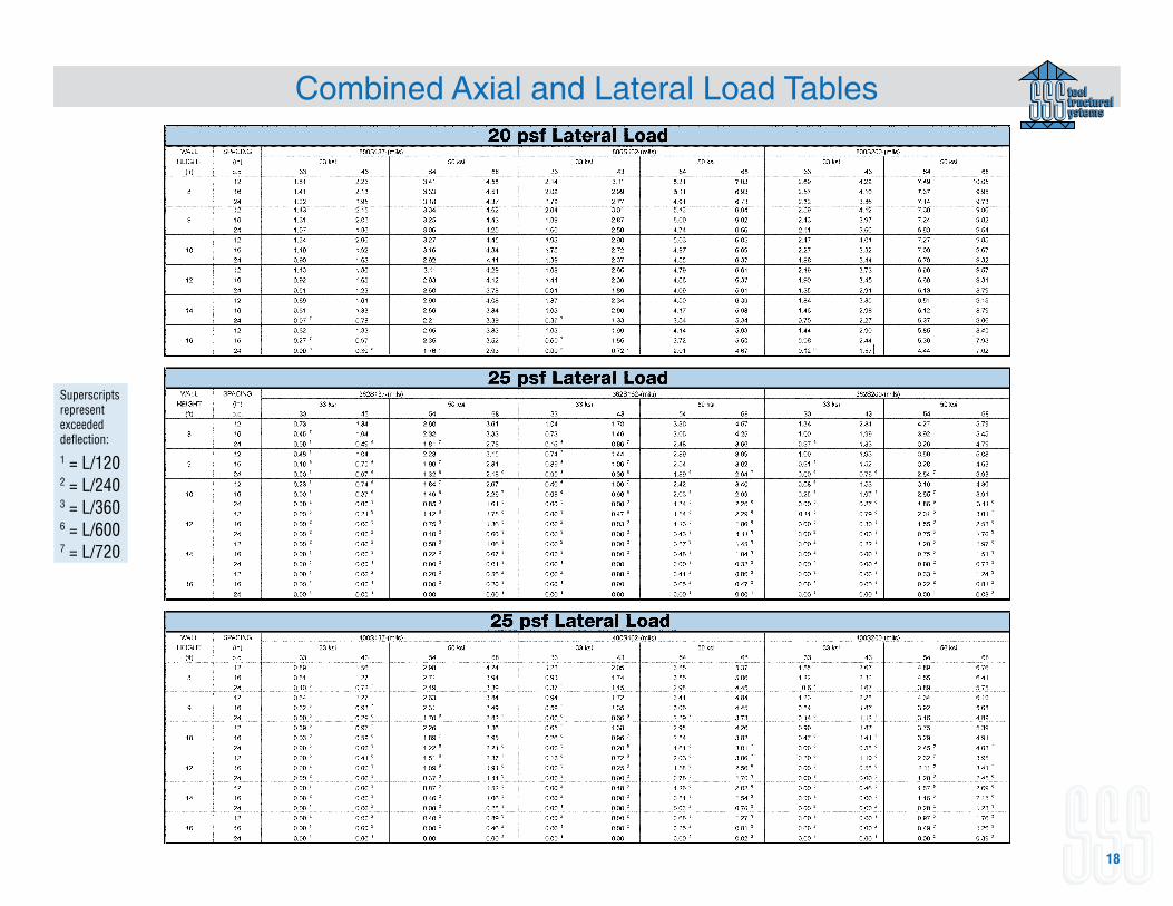
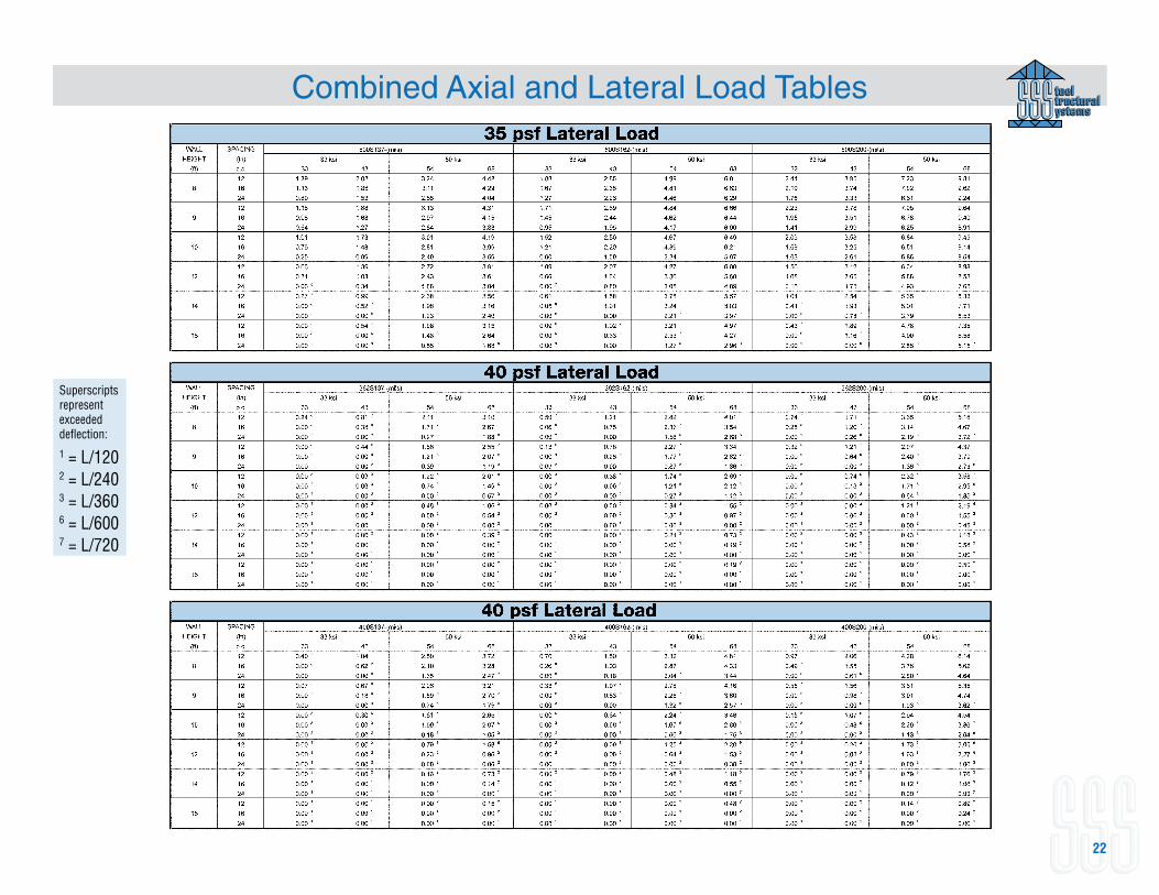
Combined Axial and Lateral Load TablesCombined Axial and Lateral Load Table Notes
1. Allowable axial loads listed in kips (1 kip = 1000 lb).2. Allowable axial loads determined in accordance with section C5 of the NASPEC, with section D4 used for treatment of punchouts.3. Listed lateral pressures and axial loads have not been modified for strength checks based on wind/earthquake or multiple transient loads.4. Allowable axial loads based on bracing KyLy = KtLt = 48 inches.5. Superscripts represent exceeded deflection: 1 = L/120 exceeded; 2 = L/240 exceeded; 3 = L/360 exceeded; 6 = L/600 exceeded; 7 = L/720 exceeded. 6. Lateral pressures have been multiplied by 0.7 for deflection checks.7. Studs are assumed to be adequately braced to develop full allowable moment, Ma.8. Check end reactions for web crippling.
Superscripts represent exceeded deflection:
1 = L/1202 = L/240 3 = L/3606 = L/6007 = L/720

15
Combined Axial and Lateral Load Tables
Superscripts represent exceeded deflection:
1 = L/1202 = L/240 3 = L/3606 = L/6007 = L/720
16
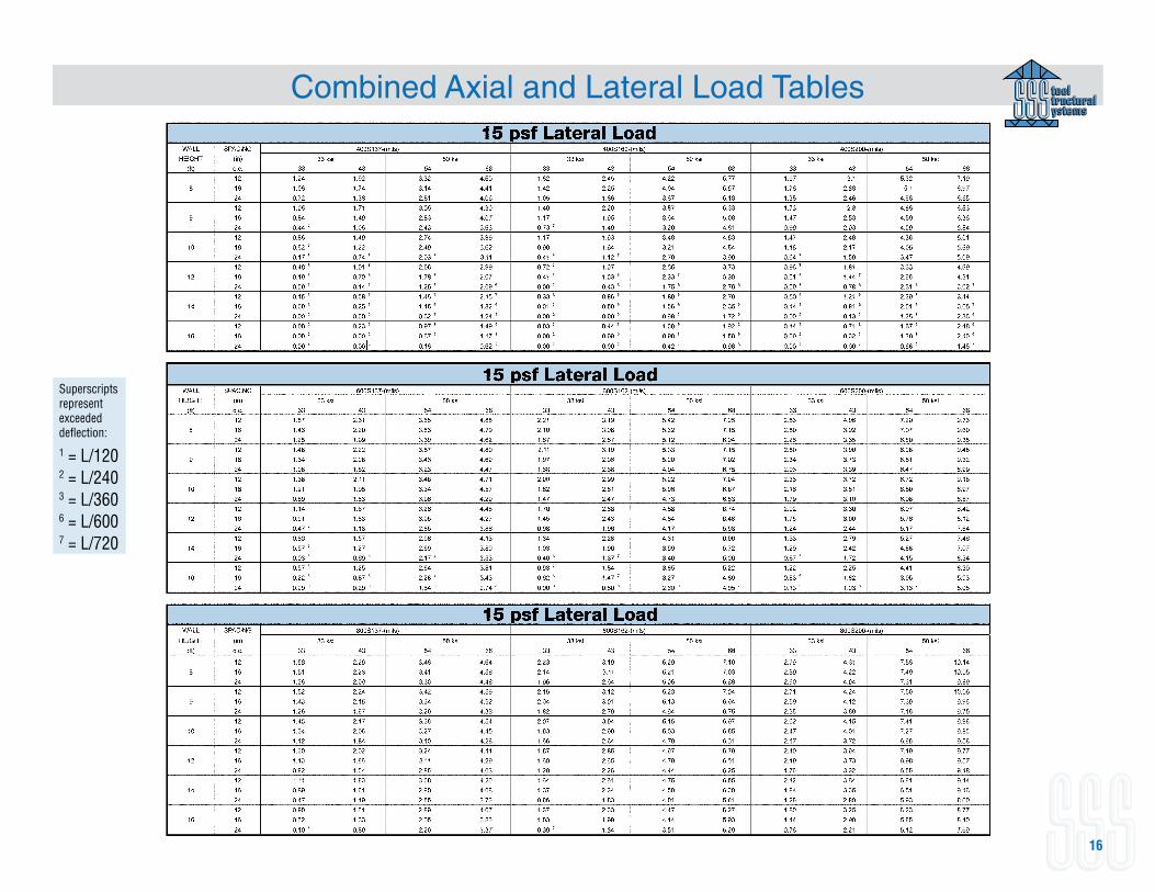
Combined Axial and Lateral Load Tables
Superscripts represent exceeded deflection:
1 = L/1202 = L/240 3 = L/3606 = L/6007 = L/720
17
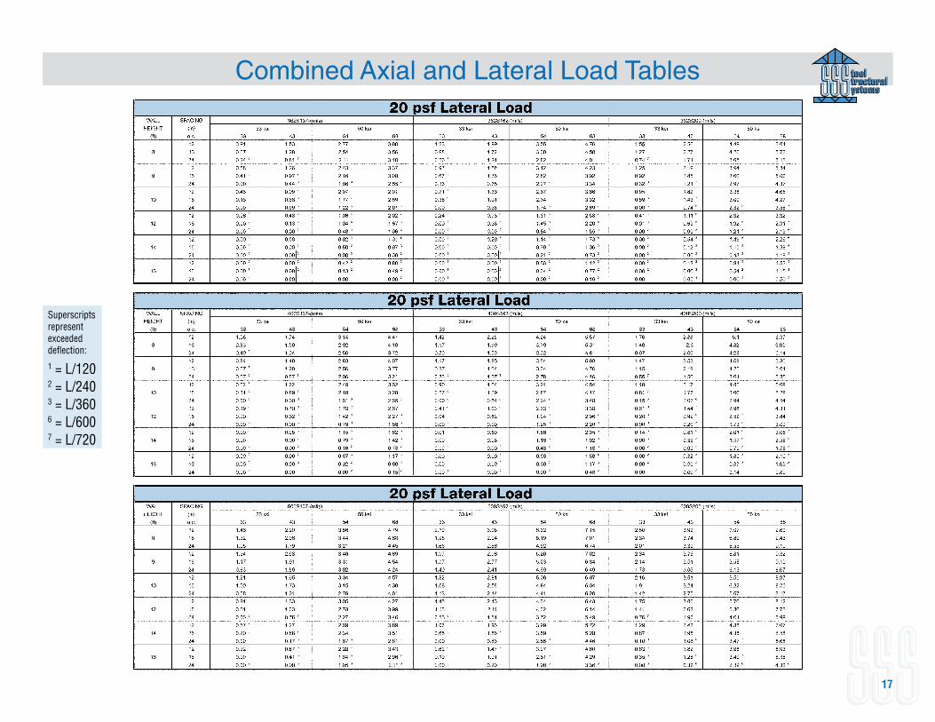
Combined Axial and Lateral Load Tables
Superscripts represent exceeded deflection:
1 = L/1202 = L/240 3 = L/3606 = L/6007 = L/720
18
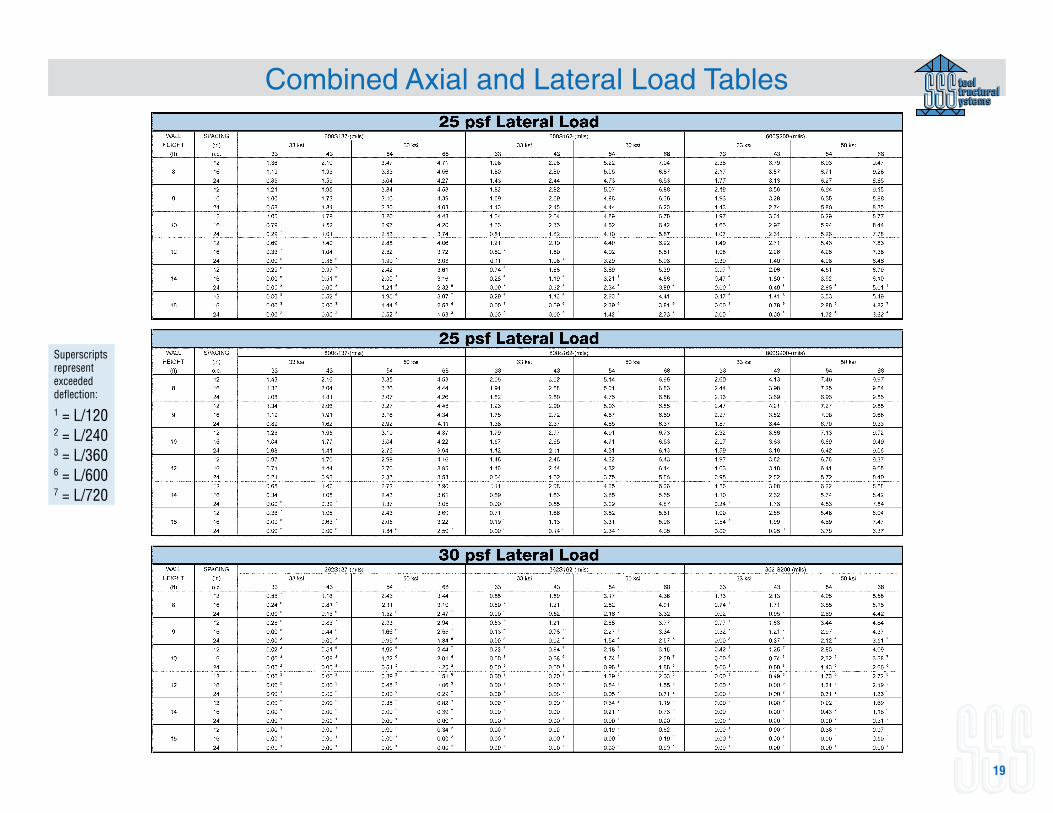
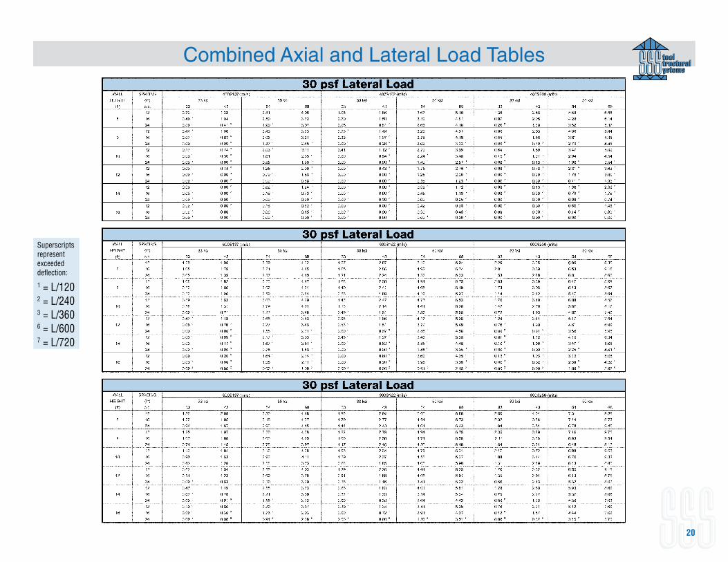
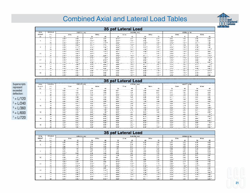
Combined Axial and Lateral Load Tables
Superscripts represent exceeded deflection:
1 = L/1202 = L/240 3 = L/3606 = L/6007 = L/720
19
Combined Axial and Lateral Load Tables
Superscripts represent exceeded deflection:
1 = L/1202 = L/240 3 = L/3606 = L/6007 = L/720
20
Combined Axial and Lateral Load Tables
Superscripts represent exceeded deflection:
1 = L/1202 = L/240 3 = L/3606 = L/6007 = L/720
21
Combined Axial and Lateral Load Tables
Superscripts represent exceeded deflection:
1 = L/1202 = L/240 3 = L/3606 = L/6007 = L/720
22
Combined Axial and Lateral Load Tables
Superscripts represent exceeded deflection:
1 = L/1202 = L/240 3 = L/3606 = L/6007 = L/720
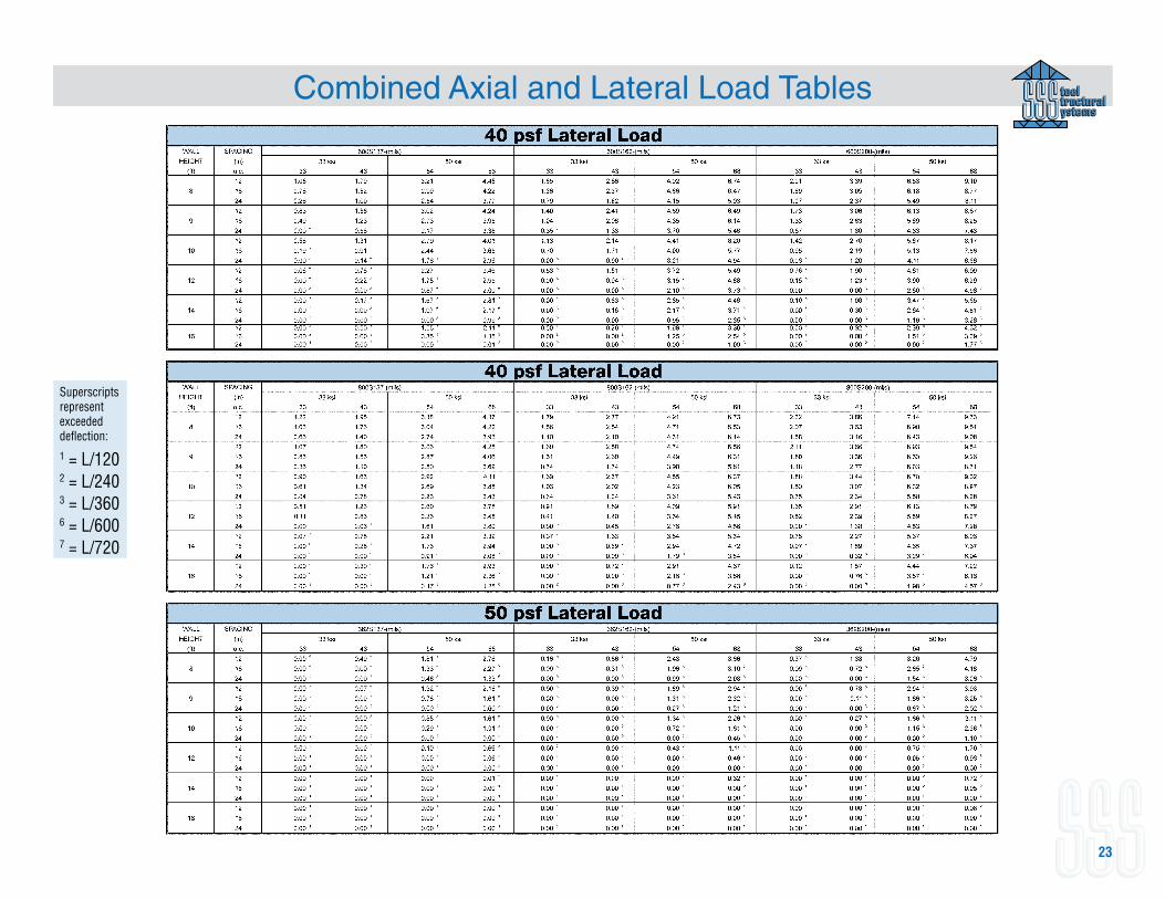
23
Combined Axial and Lateral Load Tables
Superscripts represent exceeded deflection:
1 = L/1202 = L/240 3 = L/3606 = L/6007 = L/720
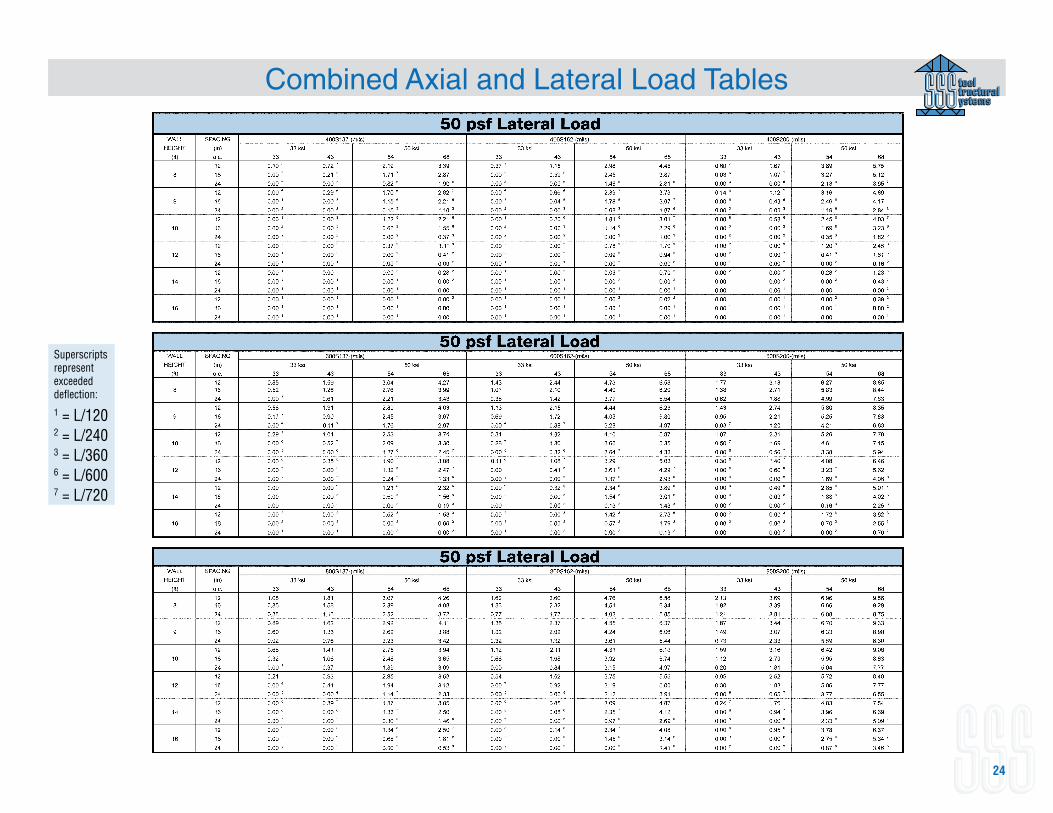
24
Combined Axial and Lateral Load Tables
Superscripts represent exceeded deflection:
1 = L/1202 = L/240 3 = L/3606 = L/6007 = L/720
25
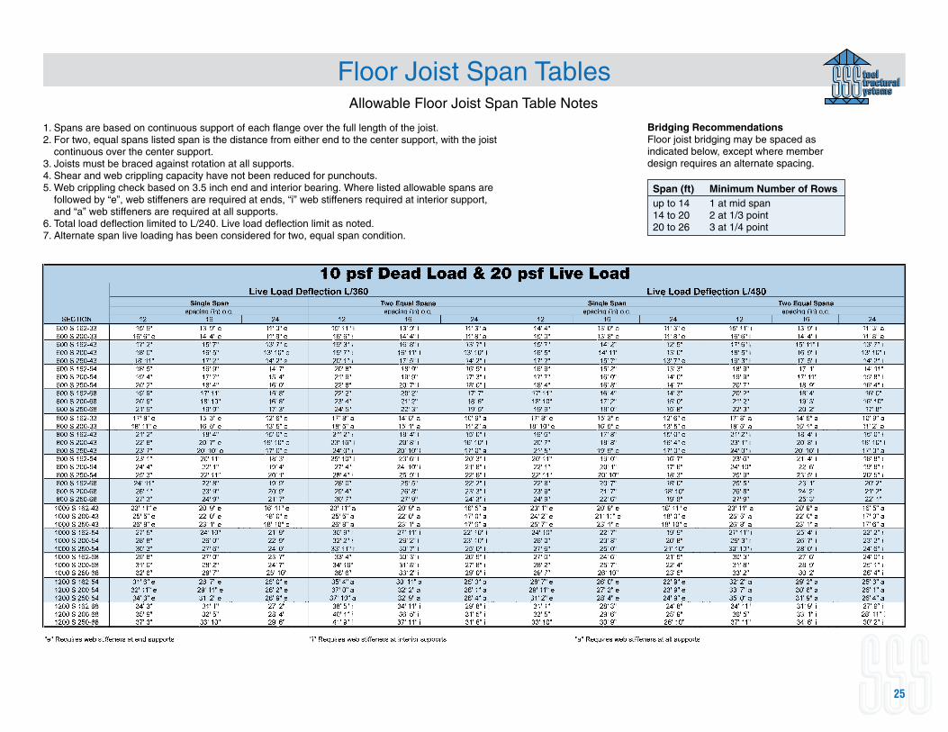
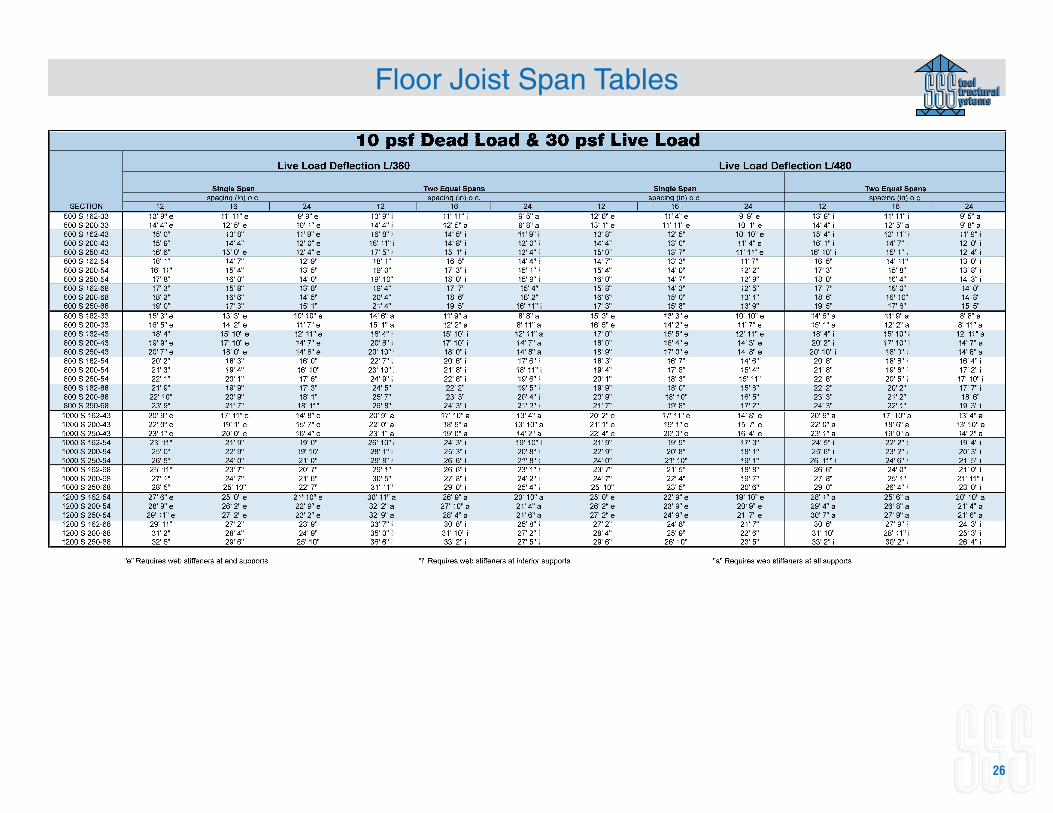
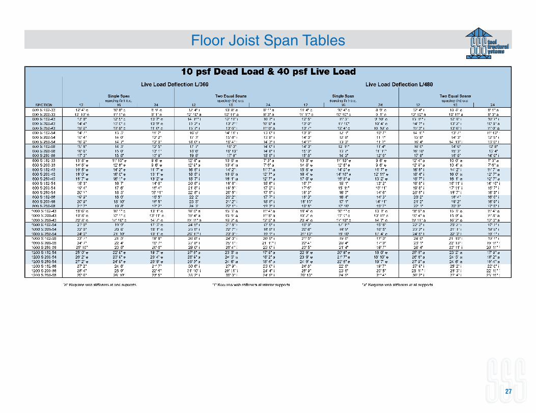
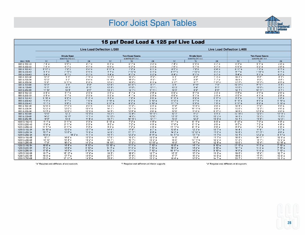
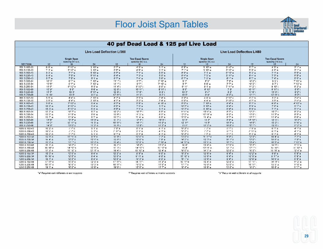
Floor Joist Span TablesAllowable Floor Joist Span Table Notes
1. Spans are based on continuous support of each flange over the full length of the joist.2. For two, equal spans listed span is the distance from either end to the center support, with the joist
continuous over the center support.3. Joists must be braced against rotation at all supports.4. Shear and web crippling capacity have not been reduced for punchouts. 5. Web crippling check based on 3.5 inch end and interior bearing. Where listed allowable spans are
followed by “e”, web stiffeners are required at ends, “i” web stiffeners required at interior support, and “a” web stiffeners are required at all supports.
6. Total load deflection limited to L/240. Live load deflection limit as noted.7. Alternate span live loading has been considered for two, equal span condition.
Bridging RecommendationsFloor joist bridging may be spaced as indicated below, except where member design requires an alternate spacing.
Span (ft) Minimum Number of Rowsup to 14 1 at mid span14 to 20 2 at 1/3 point20 to 26 3 at 1/4 point
26
Floor Joist Span Tables
27
Floor Joist Span Tables
28
Floor Joist Span Tables
29
Floor Joist Span Tables
30
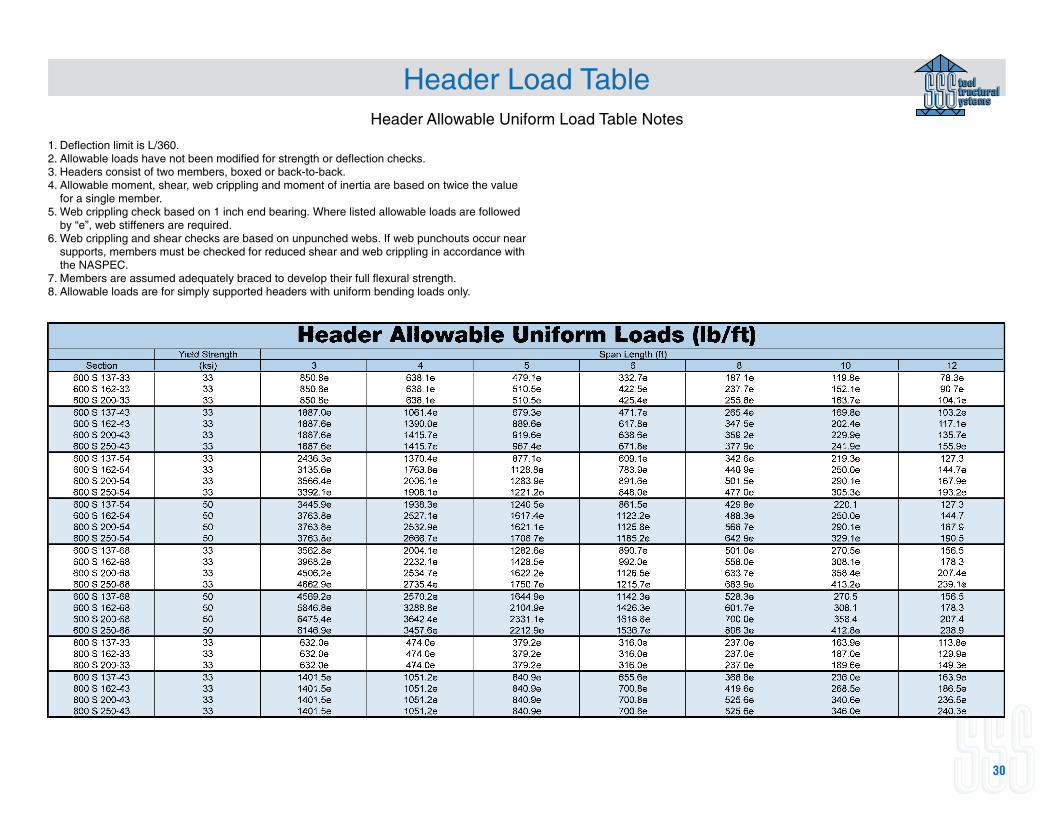
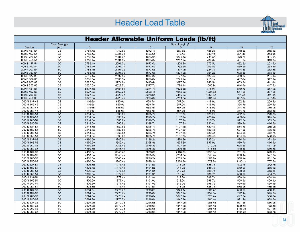
Header Load TableHeader Allowable Uniform Load Table Notes
1. Deflection limit is L/360.2. Allowable loads have not been modified for strength or deflection checks.3. Headers consist of two members, boxed or back-to-back.4. Allowable moment, shear, web crippling and moment of inertia are based on twice the value
for a single member.5. Web crippling check based on 1 inch end bearing. Where listed allowable loads are followed
by “e”, web stiffeners are required.6. Web crippling and shear checks are based on unpunched webs. If web punchouts occur near
supports, members must be checked for reduced shear and web crippling in accordance with the NASPEC.
7. Members are assumed adequately braced to develop their full flexural strength.8. Allowable loads are for simply supported headers with uniform bending loads only.
31
Header Load Table
32
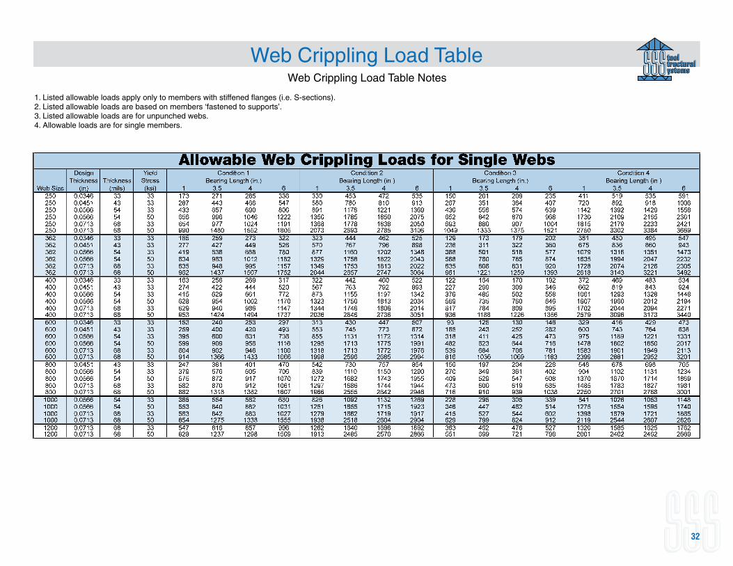
Web Crippling Load TableWeb Crippling Load Table Notes
1. Listed allowable loads apply only to members with stiffened flanges (i.e. S-sections).2. Listed allowable loads are based on members ‘fastened to supports’.3. Listed allowable loads are for unpunched webs.4. Allowable loads are for single members.
33
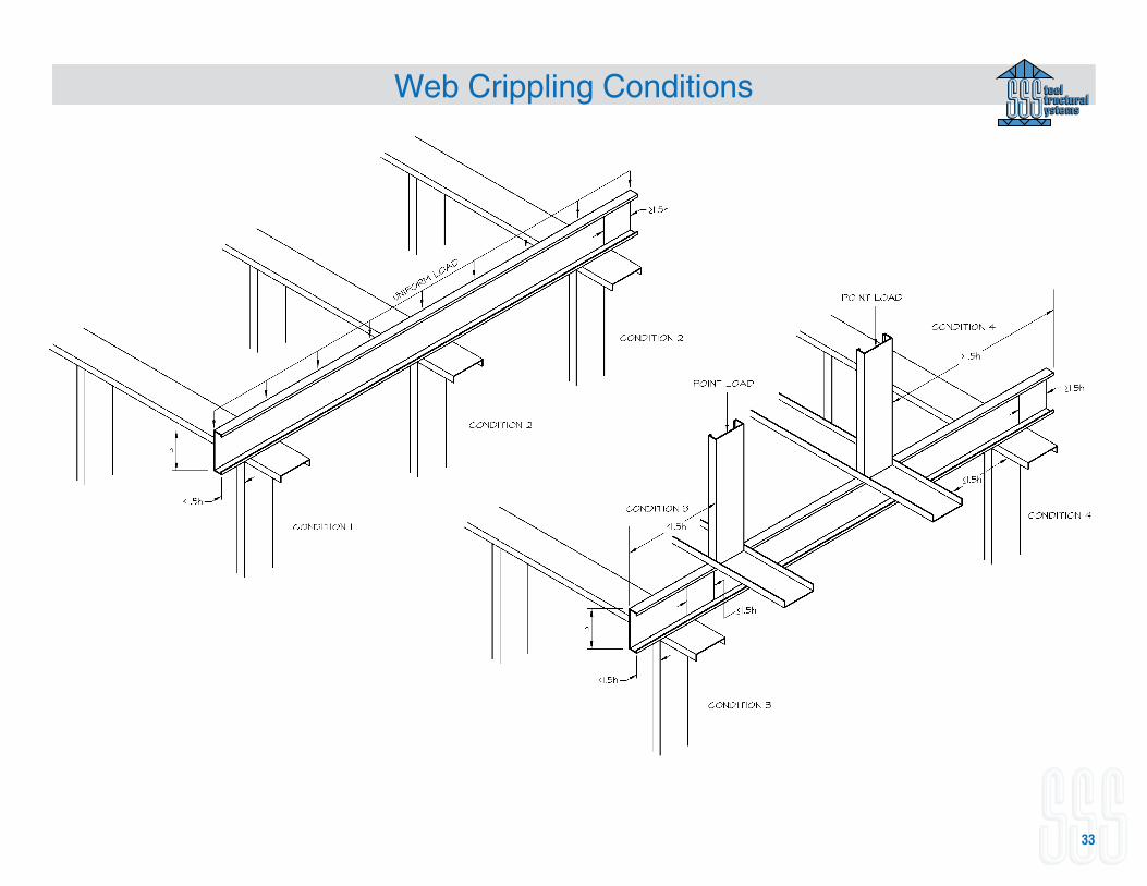
Web Crippling Conditions
34
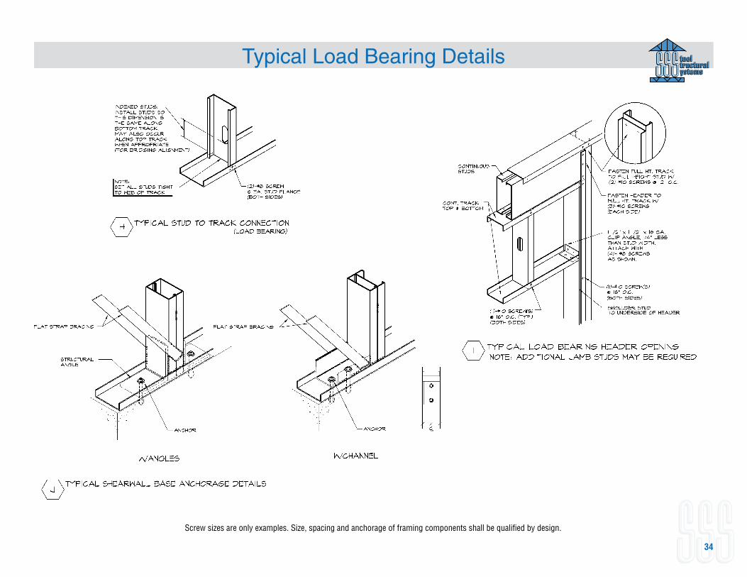
Typical Load Bearing Details
Screw sizes are only examples. Size, spacing and anchorage of framing components shall be qualified by design.
35
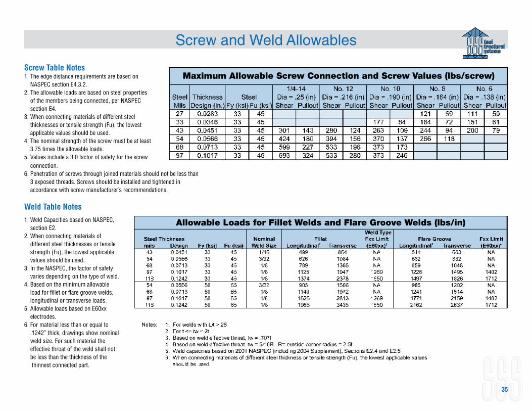
Screw Table Notes1. The edge distance requirements are based on
NASPEC section E4.3.2.2. The allowable loads are based on steel properties
of the members being connected, per NASPEC section E4.
3. When connecting materials of different steel thicknesses or tensile strength (Fu), the lowest applicable values should be used.
4. The nominal strength of the screw must be at least 3.75 times the allowable loads.
5. Values include a 3.0 factor of safety for the screw
Screw and Weld Allowables
1. Weld Capacities based on NASPEC, section E2.
2. When connecting materials of different steel thicknesses or tensile strength (Fu), the lowest applicable values should be used.
3. In the NASPEC, the factor of safety varies depending on the type of weld.
4. Based on the minimum allowable load for fillet or flare groove welds, longitudinal or transverse loads.
5. Allowable loads based on E60xx electrodes.
6. For material less than or equal to .1242” thick, drawings show nominal weld size. For such material the effective throat of the weld shall not be less than the thickness of the thinnest connected part.
Maximum Allowable Screw Connection and Screw Values (lbs/screw)
connection.6. Penetration of screws through joined materials should not be less than
3 exposed threads. Screws should be installed and tightened in accordance with screw manufacturer’s recommendations.
Weld Table Notes
Allowable Loads for Fillet Welds and Flare Groove Welds (lbs/in)