60 - subtelforum.com · turku we-fi n4 5n f ws aruba arica lurin punta carnero baranquilla punto...
43
60 n o v 2011 ISSn 1948-3031 voice of the Industry Subsea Technology Edition In This Issue: Cable Landing Station network Convergence Evolving new and Existing Submarine networks into the Terabit Age Real-Time Marine Environmental Monitoring 10th Anniversary Edition
Transcript of 60 - subtelforum.com · turku we-fi n4 5n f ws aruba arica lurin punta carnero baranquilla punto...

60n o v
2011ISSn 1948-3031
voiceof the
Industry
Subsea Technology Edition
In This Issue:Cable Landing Station network Convergence
Evolving new and Existing Submarine networks into the Terabit Age
Real-Time Marine Environmental Monitoring
10thAnniversary Edition

2
Welcome to the 10th anniversary issue of SubTel Forum!
When Ted and I established our little magazine in 2001, our hope was to get enough interest to keep it going for a while. To say we started on a shoestring would be an over estimate; it was more like a few pieces of twine from the shed that we tied together.
As you may know, tin is the traditional material for the 10th wedding anniversary, and I guess, in a weird way, we have been wedded to this industry since 2001. A funny, tangential thought came to me about how, as a kid, we would make a tin can phone to talk to one another. We could talk, literally, from room-to-room, or even around a corner!
I suspect Robert Hooke’s 17th century device has been lost to the newer generations, so for those more inventive the directions are:
Take two metal cans and cut off one end on each. Be sure not to leave any sharp edges! If there are some, you can cover the rim with electrical tape. Make a small hole in the bottom of each can. Now take a long piece of string. Thread the string through the hole in each can, and tie a knot in each end so it can’t pull back through the hole. Now get two kids to hold the cans so that the string is taut. As one speaks into a can, the other listens in the other can. You’ll be surprised at how well this works.
Today, the twine may be gone, but we still keep things on a small basis, just a few of us, and we like it that way. We believe we possess an intimacy with our readers and supporters that slick media can’t, yet we are regularly amazed by the quality of interest in what we do.
With 2012 beginning soon, our 11th year, we have a few enhancements to the SubTel Forum brand which we will be rolling out during the course of the year, and which we believe will further enhance your utility and enjoyment. We will do so with two key founding principles always in mind, which annually I reaffirm to you, our readers:
That we will provide a wide range of ideas and issues;
That we will seek to incite, entertain and provoke in a positive manner.
So here’s to you, our readers and supporters. Happy Anniversary and thank you as always for honoring us with your interest.
ISSN 1948-3031Submarine Telecoms Forum is published bimonthly by WFN Strategies. The publication may not be reproduced or transmitted in any form, in whole or in part, without the permission of the publishers. Submarine Telecoms Forum is an independent com mercial publication, serving as a freely accessible forum for professionals in industries connected with submarine optical fibre technologies and techniques. Liability: while every care is taken in preparation of this publication, the publishers cannot be held responsible for the accuracy of the information herein, or any errors which may occur in advertising or editorial content, or any consequence arising from any errors or omissions. The publisher cannot be held responsible for any views expressed by contributors, and the editor reserves the right to edit any advertising or editorial material submitted for publication.Contributions are welcomed. Please forward to the Managing Editor:
PUBLISHER
Wayne NielsenTel: +[1] 703 444 2527
Email: [email protected]
EDITOR
Kevin G. SummersTel: +[1] 703 468 0554
Email: [email protected]
Copyright © 2011 WFN Strategies

3
Exordium Wayne Nielsen 2
News Now 5
Cable Landing Station Network Convergence Brian Lavallée 9
Evolving New and Existing Submarine Networks into the Terabit AgeColin Anderson & Dr. Steve Grubb
17
Real-Time Marine Environmental Monitoring Using Cable TechnologyStephanie Ingle, Ken du Vall & Jeffrey Snider
25
Cloud Computing and the Network Martin Foster 32
Back Reflection Stewart Ash 37
Conferences 39
Letter to a Friend Jean Devos 40
Advertiser Index 42
Coda Kevin G. Summers 43
In This Issue...
10thAnniversary Edition

4
2003 20052006
20072008
2009 2010 2012
2002
submarine cable
ALMAnAC2011 edit ion
Su
bm
arin
e C
ab
le A
lman
ac - 20
11 e
ditio
n
21495 Ridgetop C
ircle, Suite 201 | Sterling, VA 20166, U
SA
Compliments of
2004
Submarine Telecoms Industry Calendar
494.8% map and surrounding rectangle locked
MESTREUMAG
DUBRAZZO
CORFU
DUBROVNIK
SPLIT
RIJEKA
ATHENS
AD
RIA 1
ODESSA
NOVOROSSIYSK
ISTANBUL
UIT R
RUTI
MARMARIS
LEKHAINA
TEL AVIV
EMOS-1
KAFOSMANGALIA
VARNASCOFS B
TARTOUS
ALEXANDRIA
RAT
EL
A
EL V
MAZARA
NAHARIYACIOS
DM SCA O
UGARIT
BEIRUT
IZMIR
TU-IS
POTI
SOCHI
G-R
PORT SAID
SEA-ME-WE 2
BIZERTE
SEA-ME-WE 3
ARIANE 2
L GF A
GF
LA
FLAG
SEISIMBRIA
PENMARCH
OSTENDE
NORDEN
BLAABJERG
2 E
W-
EM
-A
ES
MARSEILLES
ALGIERS
2 L
AP
LA
PALMA
TETOUAN
MAT 2
MAT
2
VALENCIA
BARCELONAA
1
BRM
AR
SAVONA
BA
RAV
S
PENBAL 3PENBAL 5
PENBAL 4
BUDE
APOLLO
SYLT
ALKMAAR
VESTMANNAEYJAR
REDCAR
APOLLO
CAA
3
NTT
CAT 3
ANT
LONG ISLAND
LANNION
FLA ATL N IC
GA T
FG LA TIC
LA ATN
FLAG ATLANTIC
LAG L N I
F AT A T C
MANASQUAN
ST
A-2
CO IIILUMBUS
CO BU ILUM S II
CONILESTEPONA
LISBON
MADEIRA
ST HILAIRE
CASABLANCA
C L MS I
O U BU I
CAPE TOWN
ATLANTIS-2
AT
LN
T2
AIS
-
EURAFRICA
CAPE VERDE ISLANDS
CS
AW/
3 -T
AS
AT
3W
S
S-
/A
C
WA
T-3
/A
SC
S
WA
T-3
/A
SC
S
SA
T-3
/WA
SC
DAKAR
ABIDJAN
CONAKRY
ACCRA
LOMECOTONOU
LAGOS
PORT HARCOURTDOUALA
LIBREVILLE
LOUANDA
WALVIS BAY
YELLOW
0 ATLANC
36
TI
60 TI
3 A LANT C
DUBLIN LIVERPOOL
PTATBREAN
RIO
JA
SANTANDER
II SU
BM
ULOC
EN
N,
P
CA
46
CHIPONA
A
PE
CN
5
N
ACIRFA
RU
E
KP
A-
4
U-S
IN
3 E
W-E
M-A
ES
RODILES
T 9AT-
TERSCHELLING
AT-1T
0
T-1TA1
TAT-12
SWANSEA
TTA -13
FRANCE-ITALY
ITALY-MONACO
ITALY-ALBANIA
ITALY-GREECE
ITALY-MALTA
ITALY-TUNISIA
ITALY-LIBYA
TRAPANI
KELIBIA
MONACO
OTRANTO
TRIPOLI
CATANIA
BARI
DURRES
MALTAKHANIA
AJACCIO
ARANCI
AZORES
HOLLYWOOD
WEST PALM BEACH
CANCUN
COLUMBUS II
COLUMBUS II
-1TAT 3
MANAHAWKIN
TAT-11
TAT-14
A OP LLO
A 2T T-1
TAT-14
360 TL NTICA A
BERMUDA
T4
AT-1
BOSTON
TUCKERTON
HALIFAX
PTAT
TP
TA
FORTALEZA
RIO DE JANEIRO
PUNTA ARENAS
PORT ALBERNI
SEATTLE
PACIFIC CITY
BANDON
POINT ARENA
MORRO BAYSAN LUIS OBISPOGROVER BEACH
TIJUANA
MAZATLAN
TPC-4
HARBOUR POINT
-PC 1
PC-1
CHINA-US
CHINA-US
CARACAS
PAC-1
PA
-1C
PAC-1
PA
C-1
PC
-1
A
HAWI -4
AI
AI -
HAWI 5
OAHU
JUNEAU
ANCHORAGE
GCI
IG
C
SEWARD
NP
C
PCN
AUCKLAND
TAKAPUNA
HAWAII
FIJI
O
S
SU
TH
ER
N C
RO
S
H
SO
UT
ER
N C
RO
SS
O
E
SU
THR
NC
RO
SS
UHE
N
SOT
R CROSS
E
SO
UTH
R C
RO
SS
N
TPC-5
TPC 5-
TPC-5
TPC-3
JAPAN-US
AN
SJ PA -U
JAPAN-US
1-U
R-KD
NID
O
BA AL CIT
1 ST-EWS
DUK- K 4
TALLINN
KARSLUNDE
MAADE
KRISTIANSANDLYSEKIL
GEDSER BORNHOLM
KOLOBRZEG
KARDLA
YSTAD
STOCKHOLM
SCARBOROUGH
KINGISEPP
WINTERTON
NYNASHAMN
VENTSPILS
SW-LATVIA
ST VALERY
OSTHAMMAR
RAUMA
NORRTALJE
TURKU
WSE-FIN 4
5NIF-EWS
ARUBA
ARICA
LURIN
PUNTA CARNERO
BARANQUILLA PUNTO FIJO
COLON
PAN-AM
BLUEFIELDS
PUERTO LIMONCARTAGENA
PUERTO PLATA
CAT ISLAND
NASSAU
TULUM
LADYVILLE
PUERTO BARRIOSPUERTO CORTES
TRUJILLO
PUERTO CABEZAS
RIOHACHA
COLUU
MBS III
1-S
OC
R
A
-
ARCOS
1
TORTOLAANGUILLA
ST MARTIN
ST KITTSANTIGUA
GUADELOUPE
DOMINICA
MARTINIQUE
ST LUCIA
BARBADOSST VINCENT
GRENADA
TRINIDAD
MONTSERRAT
KINGSTON
VERO BEACH
CAYMAN
EC
FS
EF
CS
CA
AR
C
SANTO DOMINGO
S-1TC
PA
N-A
M
CA
YM
AN
-JAM AA CI
CAYENNE
AE
CS
I
MRI
A I
AM
ERIC
AS II
CURACAO
ME
IC
A
RAS I
AE
RIC
AS I
M
ST THOMAS
TOLU
PUERTO LEMPIRA
MYA 1
A
MYA 1
A
ATLATIC
CR
OSSIN
G
N
NGEMI I 1
E1
G MINI
360 TL NTICA A
360 ATLANTIC
E I G M NI 2
GEM N I I 2
VALPARAISO
BUENAVENTURA
SC
A
SAC
SA
C
SA
C
CS
A
AS
C
SA
C
AT
LA
NT
IS-2
AT
LA
NT
IS-2
TL
AN
TIS
2
A
-
FLORIANOPOLIS
MALDONADO
UN
ISU
R
PINANG
COCHIN
MAURITIUS
REUNION
DURBAN
MUMBAI
COLOMBO
PYAPON
MEDAN
PERTH
JAKARTA
MUMBAI
SUEZ
KARACHI
JEDDAH
DJIBOUTI
ADEN
MUSCAT
FL
AG
SEA-ME-W
E 3
E-
E-WE 3
SA
M
E-
S
EA
-MW
E3
SM
-
EA
-E
WE
3
SIHANOUKVILLE
BRUNEI
DANANG
MACAUHONG KONG
SHANTOU
PUSAN
BATANGAS
SHANGHAI
FANGSHAN
SEA-ME-E 2
W
SA
-E
WE
EM
-2
SA
-E
WE
EM
-3
M2
SE
A-
E-W
E
SEA-M2
E-WE
PLERIN
AQABA
LG
FA
LG
FA
FLAG
FLAG
FL
AG
SATUN
MERSING
SONGKHLA
MIURA
NINOMAYA
GFLA
LA
F
G
FA
GL
FLAG
AUCKLAND
FIJI
SO
UH
ER
N
RS
S
TC
OSO
UT
HE
RN
R
OS
CS
SO
UTH
ER
N C
S
RO
S
TPC-5
PC-3T
JA AN-USP
TPC-4
C-1P
PC-1
CHINA-US
CHINA-US
PCN
TPC-5
JAPAN-US
AJIGAURA
NP
C
-PC
1
C 1P -
PTC
-4
TPC-3
KITA-IBARAKI
OKINAWA
GUAM
CHONGMING
KIOJE
MIYAZAKI
CHINA-USCHINA-US
CH
INA
US
-
CH
N-
S
IA
U
SU-ANIHC
HINA-C
US
SYDNEY
PR
IM E
ST
AC
A
RIM
WE
ST
PA
C
PCR
M W
ES
A
I
T
PR
IM E
ST
AC
A
PA
CR
IM
AS
ET
MURUYAMA
AJC
AJ
C
AC
J
AJC
OUTHERN CROSS
S
A M N T S A 2
PORT HEDLAND
PHETCHABURI
CA
PN
AP
CN
AP
CN
APC
N
CA
PN
AP
CN
KUANTANP
N
AC
2
P2
AC
N
APCN2
N2APC
CNAP
2
APCN2
S
-M-W
3
EA
E
E
BALER BAY
PTG
SAFE
AF
SE
SAFE
SAFE
SA
FE
NAKHODKA
TAEAN
HAMADACHEJU
QINGDAO
NANHUI
R-J
-K
KJ-
C-J
Main International Submarine Cables
www.subtelforum.com
NT AL TA IC CROSSING
ST CROIX
1-S
OC
R
A
1-S
OC
RA
APH O 2R ID TE
COURTMACSHERRY
LANDS END
GRAN CANARIA
C
SA
W/3-
TA
S
NAOETSU
CYPRUS
PALERMO
AR
IAN
E 2
HIBERNIA
I RN AH BE
I
IE
HB
RNIA
SANTOS
SALVADOR
BOCA RATON
PUERTO SAN JOSE
Sa
-1m
Sa
m1-
1S
am
-
a-
Sm
1
Sa
m-1
m-1
Sa
Sam-1
Sm
-1a
a 1S m-
S
JASU
RA
U
TP SC
BANGLADESH
S
Ban
gla
desh
-in
gp
ore
a
-C 1NUA S
RHODE ISLAND
PUNTA CANA
SAN JUAN
MAC
CM
A
PORT AU PRINCE
HAVANA
SANTIAGODE CUBA
NAUTILUS
SULIT
UA
N
PROVIDENCIALES
CROOKED ISLAND
NA
UTILUS
AT
-2S
S-
AT
2
WALL
BARNSTAPLE
htro Nctinatlasnra TOMTYC
thou SticC saY tT lanM TO ran
OMTYC
OMTYC
TYCOMTYC
OM
NEDONNA
LOS ANGELES
MOCYT/CIFICAP GALF
FLAG
PA
CIF
IC/T
Y
MC
O
AG CI IC YFL PA F /T COM
F G P CIFIC/TY OMLA A C
CHIKURA
EMI
TOYOHASHI
FL
G P
AC
IIC
/TC
AF
YO
M
F A PA F /T COML G CI IC Y
C2
C
C2CC
2C
CC2
TANSHUI
TOUCHENG
5 EG-KU
1A-EGNAP
SE
A-M
E-W
E 3
SHIMA
VISHAKHAPATNAM
KUALALUMPUR
SINGAPORE
ME
AS
AT
THISTED
FAEROE ISLANDS
FUJAIRAH
KUWAIT
AL MANAMAH
DAS
FOG
T Soja & Associates, Inc.The Leader in Global Telecom Market Analysis
ASEAN (BRUNEI - MALAYSIA - PHILIPPINES)ASEAN (MALAYSIA - THAILAND)ASEAN (SINGAPORE - BRUNEI)ASIA - AMERICA NETWORK (AAN)BAHAMAS-2BALTIC CABLE SYSTEM E-W (SWEDEN - LITHUANIA)BALTIC CABLE SYSTEM North I (SWEDEN - FINLAND)BERYTAR (BEIRUT - SAIDA)BERYTAR (LEBANON - SYRIA)BERYTAR (TRIPOLI - BEIRUT)BOTHNIA (SWEDEN - FINLAND)BRITISH TELECOM - TELECOM EIREANN-1CELTICCIRCE - (LONDON-AMSTERDAM)CIRCE - (LONDON-PARIS)CONCERTO#1CROATIA - ITALY-1CROATIA DOMESTIC (RIJEKA - ZADAR - SPLIT)Danica North / SouthDENMARK - GERMANY-1 (ESBJERG - DUNE)DENMARK - GERMANY-2DENMARK - NORWAY-5
DENMARK - NORWAY-6DENMARK - POLAND-2DENMARK - SWEDEN-1DENMARK - SWEDEN-15DENMARK - SWEDEN-16DENMARK - SWEDEN-18EAST ASIA CROSSING (EAC) - PHASE 2EAST ASIA CROSSING (EAC) - PHASE 1ESAT IESAT IIEUROTUNNELFCI -ONEFINLAND - ESTONIA (SF-ES 2)FINLAND - SWEDEN (SF-S 4)FINLAND - SWEDEN (SF-S 5)GERMANY - SWEDEN-4GERMANY - SWEDEN-5GREECE - MONTENEGROHERMES-1 (UK - BELGIUM)HERMES-2 (UK - NETHERLANDS)Hong Kong - Philippines - Taiwan Cable System (HPT)HONG KONG - JAPAN - KOREA (H-J-K)
HONTAI-2IBERIAN FESTOON (VIGO - PORTO)IBERIAN FESTOON (FARO - HUELVA)ITALY - LIBYAITALY - MALTAITALY - TUNISIA-1KATTEGAT-1MALAYSIA THAILAND EASTMALAYSIA THAILAND WESTMED Nautilus 1 (MN1)North Asia Cable SystemNorSea Com-1PANDAN - PULAU BUKOMPAN EUROPEAN CROSSINGPAN EUROPEAN CROSSING - IRISH RINGPANGEA-1 - Baltic RingPANGEA-1 - North Sea (South)REMBRANDTBALTIC CABLE SYSTEM North II (Finland - Russia)SEACN (South East Asia Cable Network)SEACN (South East Asia Cable Network)Sea-Van One
SPAIN - MOROCCOSWEDEN - FINLAND (Turku/Kista) (FINNET)SWEDEN - FINLAND (Umea/Vaasa) (FINNET)TAINO - CARIBTangerine - (UK - BELGIUM)TASMAN-3THAILAND - VIETNAM - HONG KONG (T-V-H)TRANS - CASPIAN LINK (TCL)TyCom Global Network - BalticTyCom Global Network - Eastern MedTyCom Global Network - Northern EuropeTyCom Global Network - Western EuropeTyCom Global Network - Western MedUAE - IRANUK - BELGIUM-5UK - BELGIUM-6UK - FRANCE-3UK - FRANCE-4UK - FRANCE-5UK - GERMANY-5UK - NETHERLANDS-12UK - NETHERLANDS-14
For reasons of clarity and scale, the following systems do not appear on this map
FORUMaSubm r n i e
Telecoms
1
�����������������������
An international forum for the expression of ideas andopinions pertaining to the submarine telecom industry 4th Quarter 2001
��������������
� ���������������������������������
� ������������ ��
� ���������
� ����������������
2001
2011
2004
Submarine Cable MapReleased
IndustryCalendarReleased
SubTel ForumIssue #1Published
NewsNowRSS FeedLaunched
Industry's First Podcast
Released to iTunes
Issue #61Articles Due:
6 January
?

news now AP Telecom Appointed as Emerald Networks’ Pre-Sales
Manager for International Network Development
Bangladesh Submarine Cable Company submits IPO prospectus
China Telecom and Huawei to Build Submarine Cable Between Australia and New Zealand
China Telecom: Fears Surface Over Chinese Cable
Columbus Selects Xtera’s Slte To Upgrade Cable System
Ctc Marine Projects Secures Contract On Anguille Project
Five Oceans Services Changes Name To Siem Offshore Contractors
Globacom Connects Babcock University
Google To Build Three Data Centers In Asia
Gulf Bridge International Awards Xtera Communications A Multi-Year Contract To Deploy 100G On Terrestrial And Undersea Network Upgrades
Imewe: Speeding Up Internet In Lebanon
Kinmen-Xiamen Submarine Cables To Be Completed In March
Leighton Plans Singapore Cable
Level 3 To Deploy Submarine Cable System In Colombia
Lighthouse R & D Enterprises, Inc. To Commemorate Six Years Of Collaborative Work With The Ministry Of Fisheries Wealth, Sultanate Of Oman, On One Of The World's First Cabled Ocean Observatories

Mexus Selling Cable!
Mitsubishi Electric To Upgrade Transpacific Cable Network
NCC Approves Submarine Cable Link Between Taiwan And China
Nec Finishes Upgrade Of Asia Pacific Cable
Neotel Wins WACS Cable Deal
Nexans Delivers Cable For Ireland-UK Submarine Link
NTT Com’s PC-1 Transpacific Submarine Cable To Introduce Next-Generation Optical Transmission Technology
NTT Communications Builds Its First Financial Data Centre In Hong Kong
Pacific Crossing and Infinera Complete World's First Transpacific 100 Gigabit Subsea Trial
Pacnet Expands Cloud Computing Offering With New Virtual Private Server Solution
Pacnet Speeds Digital Content Delivery Across Asia
PCCW Global and Cyta enhance their Ethernet services
SAT3: No failure Says Telkom
Sea Fibre Networks Steams Ahead with CeltixConnect “Go-Live” Date Announced
SEA-ME-WE 3 Cable Fault Causes "Unstable" Net: ISP

7
Congratulations to Submarine Telecoms Forum on reaching its 10th Anniversary. SubOptic has always been very happy with the support that SubTel Forum has given us, acting as one of our major media partners for a number of our events. We were especially pleased to be able to act as Guest Editor for an issue of SubTel Forum before the SubOptic 2010 event, something we hope to repeat in the future. I know it is hard work and it certainly was a risk when you started, but I think you have succeeded in keeping your magazine relevant and interesting, attested to by your increasing readership. Keep up the good work for the next decade. Best wishes John Horne, Secretary to theSubOptic Executive Committee
For 10 years, SubTel Forum has provided the industry with a valuable sounding board for new ideas, old reminiscences, and current events. I continue to enjoy reading STF because it consistently gives me pause for thought - a rare commodity in today's world of news flashes, talking heads, and sound bites. Best regards Julian Rawle, Managing Partner, Pioneer Consulting
For the 10th anniversary of Submarine Telecoms Forum, I would like express you all my thanks for the existence of this magazine and the wishes for a long and successful future life. In no other place I can find so much interesting information related to the submarine telecom activities and a clever column like "Letter to a friend". Thank you. Best regards.
Fabrizio Garrone
Congratulations...
10 years
8

9Brian Lavallée
Cable Landing Station network Convergence

10
Global demand for bandwidth continues to increase unabated, and is forecasted to grow at a compound
rate of nearly 50 percent annually for the foreseeable future. Although the increasing popularity of video-centric streaming content is the primary driver, an increasing number of subscribers at ever-multiplying per subscriber access rates are also fueling this growth. Increases in continental bandwidth growth inevitably affect the submarine networks interconnecting the continents, as accessed content can be located anywhere on planet earth – a situation that will only be compounded with the advent of cloud services that centralize content at a few select geographic locations. Unfortunately, the steady increase in bandwidth demand is also associated with steady price erosion for intercontinental submarine capacity.
The main concern facing submarine cable operators today and in the coming years is how to significantly reduce the operating costs of their networks. Cable Landing Stations are now being considered as a key area in the submarine network where significant reductions in power consumption, space allocation, management and equipment complexity, and operating costs can be achieved.
In a Cable Landing Station, submarine networks interconnect to terrestrial networks, usually via a backhaul network into the carrier’s inland Point of Presence (PoP). This distinct demarcation point was created primarily due to business, political, geographic, and technological factors. However, a steady convergence of optical networking technologies used in both submarine and terrestrial networks
is blurring this demarcation point and putting its physical existence into question. Maintaining an ongoing distinct network demarcation point only serves to make network equipment redundant within the Cable Landing Station, leading to increased capital and operating expenses. These costs can be significantly reduced by leveraging the convergence of optical networking technologies and exploiting network node consolidation. Successful global service providers must operate efficient end-to-end optical networks, managing their submarine and terrestrial networks assets as a single omnipresent entity and negating the need for a distinct demarcation point.
Changing SubmarineNetworking Business Drivers
The submarine networking community traditionally chose technological paths different from their terrestrial networking brethren, leading to a distinct, and relatively inefficient, interconnection point between networks. Traditional builders of submarine networks were consortia composed of national incumbents operating as peers in the construction and ongoing maintenance of submarine cables. Differentiated service offerings were not a main priority due to the absence of competition. To ensure sovereignty between the services of each of the consortium members, Cable Landing Station demarcation points were constructed to be inflexible by design, such that the shared submarine network

11
was not integrated into a consortium member’s terrestrial network. This led to managing submarine networks as distinct and separate network entities. When services were primarily low-growth voice services, this network business model was indeed economically viable. However, as traffic shifts towards connectionless high-speed data services, coupled with steady increases in competition both nationally and internationally, this legacy business model and the associated demarcated network design become less economically viable. Both consortia and single-owner cable operators must find innovative ways to significantly reduce the costs of their network assets wherever possible. The Cable Landing Station is an excellent place to start – especially legacy stations that are still being served by inefficient network configurations.
Submarine Networking Technology Evolution And Convergence
Compared to terrestrial networks, submarine networks face significant challenges due to their unique operating environment in which active electronic devices lie at the bottom of oceans, often spanning thousands of kilometers. The location of the wet plant entails repairs that are extremely costly and time-consuming, with the resulting loss of traffic often being costlier than the repair operation itself. The submarine network’s mean time to repair pales in comparison to terrestrial networks because the latter is far easier to access in an expedient and cost-effective
manner. As a result, submarine network assets are typically designed to operate for 25 years, and thus will continue to use technologies that are specifically tailored to harsh submarine operating environments. However, equipment located in land-based Cable Landing Stations can fully leverage the more rapid technological advances of terrestrial optical networks and associated cost savings from higher production volumes.
Significant technological advances in submarine networks have already occurred. Single-channel fiber optic submarine cables using electrical regenerators were replaced with multi-wavelength DWDM fiber-optic-based submarine cables and Erbium-Doped Fiber Amplifiers (EDFAs). Point-to-point networks were replaced with ring-
based topologies to improve network survivability. PDH signal formats were replaced by 5 Gb/s proprietary signals to increase submarine cable-carrying capacity. The adoption of SDH, DWDM techniques, and Optical Add/Drop Multiplexer (OADM) technologies not only increased submarine network flexibility but, more importantly, converged with terrestrial networks for simplified network interconnections. As this steady convergence of optical networking technology continues, redundant inefficiencies call the legacy requirement for a distinct submarine-to-terrestrial network demarcation point into question.

12
Cable Landing Station Evolution
Figure 1 illustrates the traditional configuration, where the Cable Landing Station served as the junction point between the submarine wet plant and the terrestrial dry plant. The equipment facing the terrestrial network was primarily based on SDH, with line rates ranging from 2.5 Gb/s to 10 Gb/s. The equipment facing the submarine side was proprietary, with line rates typically up to 5 Gb/s. Proprietary solutions facing the wet plant were necessary at the time, because each submarine link required maximum optimization given the distances and harsh operating environments of the wet plant. This architecture is highly inefficient, and thus cost-ineffective, compared to the optical networking technologies available today. There are numerous limitations and inefficiencies with this legacy network demarcation architecture, summarized below:
Inefficient hand-off between the submarine and terrestrial networks via back-to-back optical tributaries
Substantial amount of network equipment required, much of it redundant
Significant physical space and power consumption requiring larger Cable Landing Stations
Translation to/from proprietary and standards-based signal formats
Complex cable management
required to interconnect numerous pieces of network equipment
Separate Network Management Systems (NMS) for less effective network maintenance
Limited and unintelligent bandwidth management
Significant equipment/cable sparing complexities and associated costs
Figure 1. Legacy Submarine-Terrestrial Network Demarcation Configuration
It should be noted that the adopted networking solutions were innovative at the time, producing effective and reliable solutions that served associated business models quite well. However, today’s market forces have rendered this legacy network design inefficient and cost-prohibitive based on current competition-based business models.
Terrestrial-Facing Equipment And Network Protection Equipment (Npe) Integration
Due to telecom deregulation and the initial localization of the Internet within the U.S., terrestrial optical networks were the first networks subjected to fierce competition. Fueled by investor capital and bandwidth growth, startup and traditional equipment vendors developed innovative new solutions applicable to the terrestrial-facing side of the landing station, as shown in Figure 2. Integration of duplicated network protection equipment allowed for improved protection schemes such as Transoceanic Protocol Switching (TOPS), which is a modified implementation of terrestrial ring-based protection switching. Terrestrial-facing DWDM optical interfaces also were integrated, along with pre/post optical amplifiers to further reduce the complexity of the demarcation point. Although networking equipment facing the wet plant is still clearly demarcated, the continual drive toward integration yielded several additional advantages and efficiencies, some of which are listed below:

13
Integrated DWDM optical transceivers, eliminating inefficient client-side tributary hand-offs
Integrated switch fabric, enabling a broader range of agile service offerings
Reduced amount of networking equipment and associated optical cables to manage and spare
Increased integration, resulting in reduced overall power and cooling requirements
Reduced Cable Landing Station rack and floor space requirements
Achieved substantial savings in overall capital and operational expenditures
This level of continued integration also demonstrates ongoing convergence of terrestrial and submarine equipment, resulting in savings in space, power, and cost, complemented by increased reliability, flexibility, and manageability. Advances on the submarine side include faster line rates and higher channel counts for increased capacity. The Network Protection Equipment (NPE), along with switching/grooming, can now be managed as an integral part of the terrestrial NMS for improved operations, administration, maintenance, and provisioning. For a variety of political and technological reasons, the networking equipment facing the wet plant is likely to be the last portion of the network demarcation point to be integrated. However, with the advent of innovative optical transmission technologies such as coherent modems, this last piece of networking equipment housed in a Cable Landing Stations inevitably will be integrated, since the benefits are simply too attractive to ignore.
The Fully Integrated Cable Landing Station
The complete integration of networking equipment into a single unified network node will maximize realized benefits from both capital and operational viewpoints. Wet plants were purposely designed and built to be highly proprietary so maximum reach and reliability could be achieved. This design required very expensive optical transponders that were produced in relatively small volumes,
negating the advantages of economies of scale enjoyed by terrestrial networks. New optical transmission technologies – such as 40G and 100G coherent modems originally targeted toward ultra-long-haul terrestrial networks – are equally applicable and compatible with existing and new wet plants. As a result, the final level of integration, namely the submarine-facing equipment, becomes possible, thus maximizing the advantages of complete integration while essentially erasing the terrestrial-submarine network demarcation point altogether, as shown in Figure 3. Although passive optical couplers are not typically integrated, they can be to facilitate real-time equipment inventory.
Integration facilitates the rapid adoption of several other technologies, many of which come from terrestrial networking yet are equally applicable to submarine networks, especially as network demarcation points blur or are erased altogether. By managing submarine and terrestrial network assets as a single network entity using the same or similar technologies, seamless end-to-end networking is greatly facilitated and leads to more flexible and agile service offerings. Emerging technologies that will continue to influence Cable Landing Station network designs include the following:
40G and 100G terrestrial-facing and submarine-facing DWDM line optics
Figure 2. Terrestrial-
facing equipment
and NPE integration

14
Gridless networking independent of fixed wavelength grids for improved spectral efficiencies
Multi-terabit switch fabrics that match capacities of multi-terabit submarine cable upgrades
Intelligent Control Plane-based mesh networks for improved flexibility, availability, and optimization
Migration from legacy SDH-based submarine networks to OTN-based terrestrial networks
Migration of terrestrial networks from circuit-switched services to packet-switched services
The Cable Landing Station Of Tomorrow
As shown in Figure 3, Direct Wavelength Access (DWA) allows wavelengths coming from submarine wet plants to bypass Cable Landing Station network equipment by feeding them directly into the terrestrial backhaul network to the inland PoP. DWA is not bound by limitations of the Cable Landing Station equipment, which may not yet be fully integrated. DWA also facilitates intelligent switching, and the associated highly resilient and flexible mesh networking, from within the inland PoP where the intelligent Control Plane-based switches typically reside. In some cases, the implementation of DWA brings the Cable Landing Station itself into
question. Where possible, to further reduce costs by increasing network integration, the equipment housed in the Cable Landing Station could be physically moved and integrated into the inland PoP. Equipment presently located in Cable Landing Stations, including Power Feed Equipment (PFE) that powers the submarine optical repeaters, could be physically relocated inland where possible. These items together enable the following advantages:
Elimination of the Cable Landing Station building
Elimination of the terrestrial backhaul equipment
Significant reduction in overall equipment
Figure 3.Fully integrated
Cable Landing Station network
Figure 4. Seamless end-to-end global networking

15
Faster mean time to repair and improved network availability
Significant reduction in power consumption for a greener network solution
Significant reduction in capital and operational expenditures
A single unified network node integrating the Submarine Line Terminating Equipment (SLTE) with the terrestrial backhaul network, as illustrated in Figure
4, means a single network element is managed. This allows submarine cable operators to merge their terrestrial and submarine networks over an electrical backplane enabling value and flexibility not possible using several pieces of network equipment solely to demarcate these two networks – simplified networking at a reduced cost.
Future Outlook
The physical isolation of traditional Cable Landing Stations and the terrestrial-submarine network demarcation they contain is mainly attributed to the traditional consortium business model. Neutral and physically separated Cable Landing Stations for interconnecting geographically separated continental networks was the traditionally accepted practice. However, continued price erosion and recent demands on global service providers to adopt new technologies faster, significantly increase submarine cable capacities, improve network availability, and broaden service offerings for competitive differentiation is forcing consortia and single-owner cable operators to question traditional business models and associated network configurations. Varying degrees of network integration are possible, from partially integrated submarine and terrestrial network equipment to complete elimination of the Cable Landing Station building itself, enabling submarine cable operators to decide how much integration best serves
their specific needs. Although different submarine cable operators will choose different levels of integration, the same industry trends of increasing bandwidth demands, coupled with global price erosion, are common concerns for both consortia and single-owner cable operators alike. Integration of network equipment allows submarine cable operators to effectively address both of these concerns.
Brian Lavallée is the Director responsible for Submarine Industry Marketing at Ciena

16
17
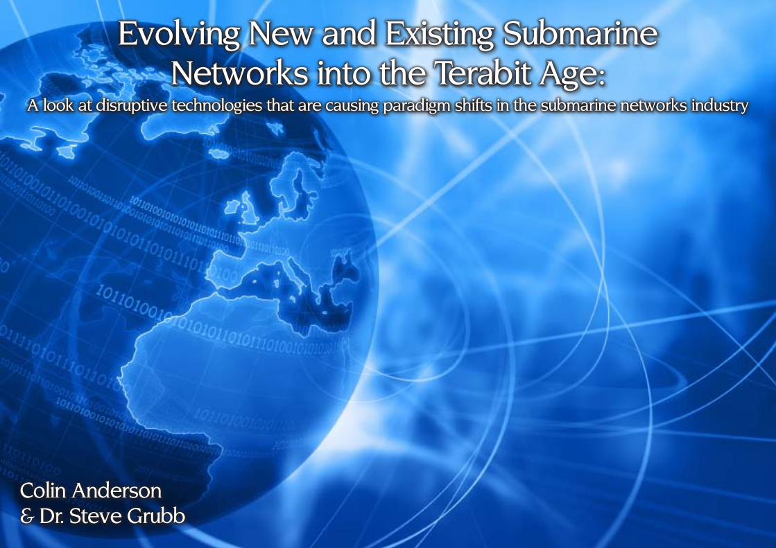
Colin Anderson& Dr. Steve Grubb
Evolving new and Existing Submarinenetworks into the Terabit Age:
A look at disruptive technologies that are causing paradigm shifts in the submarine networks industry

18
The demand for global bandwidth has forced continuous improvements of the subsea networks with new
and advanced technologies. But new technology is often a double edged sword, with some providing incremental improvements and others being disruptive. Yet it is the disruptive technologies that offer the ‘step-function’ rewards. Without disruptive technologies, we could still be getting our news from the local paper boy, rather than a continuous stream on our smartphones everywhere we go.
This article looks at optical technology, with a focus on those with a ‘step-function’ impact and a view of their impact on the subsea networks evolution.
Looking Back
Key technology advances have played a major role in improving optical network scale, costs and operations. The technology benefits are numerous, but focus on providing more (capacity, reach, automation) for less (cost, operations, complexity)
Subsea networks have arguably benefitted even more than most industries, as the multiple enabling technologies have often created synergies that have a bigger impact that their terrestrial counterparts. Let's take a closer look at some of these:
Erbium Doped Fiber Amplifier (EDFA)
The Erbium Doped Fiber Amplifier (EDFA), was commercialized into subsea networks in the mid-1990’s, slightly ahead of commercialization in terrestrial networks. Coupled with WDM, it offered a ‘step-function’ improvement in network capacity which enabled upgrades from 1.44 Gb/s per fiber pair (fp) to 200 x 10 Gb/s per fp – an increase of ~ 1400x, within just 10 years or so.
The EDFA is notable as one of the few recent technology advances for optical transmission which is not related to the advances in IC’s (integrated circuits), and also because its introduction primarily
impacted the submerged part of subsea networks.
Some argue that the EDFA fueled the ‘telecom bubble’ that burst in 2000 and 2001, but overall it was a powerful enabler for the industry, and the net result for both suppliers and purchasers was certainly positive.
Forward Error Correction
Forward Error Correction (FEC) schemes have been central to improving performance, most notably reach, in both terrestrial and subsea networks, and have become ever more powerful. The ability to implement FEC into integrated
Figure 1.Impact of Technology on Subsea Transmission Capacity.

19
circuits, or IC’s has enabled FEC evolution to follow “Moore’s Law” of continuous improvement in density, while reducing size and power.
New Fiber Types
Optical fiber manufacturers have developed sophisticated fiber types for application in submarine networks, to reduce Chromatic Dispersion (CD), although the influence of fiber design on nonlinear effects was not fully understood at the time, and Polarization Mode Dispersion (PMD), and to minimize attenuation (allowing longer inter-repeater spacing).
Subsea Laser Pumps
And the semiconductor manufacturers remaining in the market for subsea pumping lasers have continued to develop lasers with higher output power and increased reliability, enabling repeaters with higher traffic capacity and lower cost.
Reaching A Plateau
Despite evolutionary improvements since the introduction of the EDFA, the next hurdle of 40 Gb/s and 100 Gb/s wavelengths presented new challenges for long-haul trans-Atlantic and trans-Pacific links. The high bit rate wavelengths are acutely sensitive to CD, PMD, and non-linear optical degradations in the submerged plant, creating enormous risk
and potential trade-offs for any subsea project.
Yet demand for capacity continues, seemingly independent of the world’s struggling economies, at compound aggregate growth rates of 40% or higher. And although the market price per bit continues to decline, analysts conclude that the growth in demand is high enough that the overall revenue to carriers still continues to increase.
Looking For The Next ‘Step-Function’
The combination of high growth rates and aging cable systems deployed during the
boom of the late 1990’s would seem to predict the need for construction of many new subsea telecom cables in the near future. Instead, several inter-related new technologies are currently having a step-function impact on our industry. And this time the technologies are primarily related to the terminal equipment, rather than the submerged plant.
Coherent Detection
Coherent detection, a technique used to increase radio receiver sensitivity, is now being applied to optical fiber plants. Implementation of coherent detection for optical networks take the form of
Figure 2. Growth of Capacity Demand in Various MarketsReproduced courtesy of TeleGeography

20
integrated circuits using Digital Signal Processing (DSP) leverage multiple algorithms to reduce CD and PMD effects of the fiber over distance. Coherent detection is implemented as an IC and offers practicality in terms of performance, space, cost, & power consumption and benefits from Moore’s law. Finally, coherent detection protects fiber plant investments by ensuring the latest 40 Gb/s and 100 Gb/s wave operate over fiber plant deployed over 15 years ago.
Soft-Decision FEC
Yet another enabling technology which owes its practical implementation to advances in semiconductor integration is
Soft-Decision Forward Error Correction (SD FEC). The theory of such ultra-high performance error correction techniques have been around for many years, but only recently has it been feasible and economical to implement the techniques in real hardware. Soft-decision FEC complements coherent detection and advanced modulation schemes to provide truly remarkable performance of 40 Gb/s and 100 Gb/s systems, with spectral efficiencies approaching the Shannon limit, if the optical signal to noise ratio(OSNR) is high enough.
Powerful New Modulation Schemes
Powerful modulation schemes, such as Phase M o d u l a t i o n (PSK, BPSK, QPSK) and combined Phase & Amplitude m u l t i - l e v e l coding (8QAM, 1 6 Q A M , 64QAM, etc), which have been used in radio and satellite systems for many years have recently become feasible for high-speed optical systems.
These enables higher overall throughput on the wavelength while using a slower baud rate, suited to most deployed wet plants.
While enabling higher ultimate capacities for fiber, no one modulation scheme is ideal for all networks. Software programmable modulation schemes become essential to allow operators to choose their trade-offs of capacity vs. reach, or even accommodating legacy fiber network performance. Such user selectable modulation schemes, on a per wavelength basis, ensure maximum fiber utilization.
Photonic Integration
Photonic integration is the process of combining photonics with integrated circuits, by integrating hundreds of photonic components onto a single microchip the size of your thumbnail. It is the ultimate ‘step-function’ that combines as many as 600 optical functions, and over a thousand discrete components onto a single chip.
Photonic IC’s are analogous to the electronic IC’s that most people are more familiar with, which gave us advanced microprocessors, memory, Solid State Drives (SSD), and similar devices which in turn have made possible the multi-media personal computers, smart-phones, and tablet computers which we now take for granted.
Figure 3. Increase in
Semiconductor Density
(Moore’s Law)

21
State of the art photonic integration utilizes the Indium Phosphide (InP) semiconductor technologies to combine hundreds of optical components on the same substrate. Placing photonics onto IC’s brings the same manufacturing efficiencies enjoyed by the electronics industry to the optical industry, and will bring a new “Optical Moore’s law” to WDM transport. It also has been proven to deliver higher density, lower costs, lower power and extremely high reliability optical networks while massively reducing the complexity of the network itself.
Subsea networks benefit from the integration of both the optical on a single chip by vastly reducing the number of mechanical optical junctions usually required to interconnect discrete components, and the consequent reduction of optical interconnections by patch cords and optical connectors. Such mechanical junctions and cable connections are a major contributor to faults in optical transmission systems.
Terabit Super-Channels
Single channel Terabit transmission requires technology, A/D convertors and associated high speed processing which make them prohibitive for mass production for the foreseeable future. Instead, the industry is driving towards an architecture built around super-channels. The intent of super-channels is to improve spectral efficiency of the optical fiber as well as reduce the operational complexity of multi-terabit fiber plants. The introduction of super-channels eliminates the necessity for guard bands on a per wavelength basis, and enable much higher utilization of the available spectrum, while also reducing the number of channels that have to be managed on an optical system.
Protecting Your Investment While Migrating To Terabits
Key to optimizing return on investment is the ability to synergize multiple technologies to address the market need while also reducing total cost of ownership.
Combining coherent detection soft-decision FEC and advanced modulation techniques is already proving to be as impactful to submarine telecom networks as the introduction of the EDFA was, some 15 years ago, with the added protection of the fiber plant investment.
Most importantly, all of these advances are available in the submarine terminal
equipment with full compatibility with wet plant systems deployed up to 15 years ago.
As has been proven by multiple trials, notably by Pacific Crossing and Infinera, the combination of technologies can be effectively used to evolve into the terabit age while protecting past investment, with the added ability to protecting any future deployment of new subsea networks with ever higher ultimate capacities, again with lower cost per bit.
Example of a recent network upgrade: Recently Pacific Crossing (an NTT Communications Company) and Infinera announced the world’s first transpacific 100 Gb/s subsea trial [1], on a segment of PC-1 spanning 9,500 km which was first commissioned in 2001.
Potential Impact Of ‘Step Function’ Upgrades – Positive And Negative
The positive impact of such technological advances is the reduction for new subsea builds, by extending the lifetime & capacity of legacy networks far beyond the originally expected or contracted ultimate capacity. This is good news for many, as economic turmoil makes debt funding for new capital-intensive projects challenging.
The secondary impact of such technologies is that new subsea builds benefit from higher capacities, longer reach and lower risks making them more attractive from a technological standpoint. However, it may

22
take longer to actually fill such networks to capacity, which impacts the business case for such new cables.Arguably, if legacy turnkey suppliers compete fiercely in the upgrade market, they will do so at the expense of new networks and their own longevity. The upgrade market may generate revenue for legacy turnkey suppliers, but does nothing to utilize their cable-ship resources, cable factories, or submerged repeater factories. The wet plant suppliers not only need to bear the overhead costs of these facilities, they also need to keep the plant and staff ready for future new orders, so they are not forced to mothball or shutter them.
In summary, the ability to upgrade legacy networks to many times their initially expected or c o n t r a c t e d u l t i m a t e capacity is an overall negative for turnkey n e t w o r k suppliers.
Why All Subsea Owners Should Care?
The impacts of new
technologies, particularly those which have significant terrestrial and subsea market share, is more revenue generating capacity, lower costs and higher return on investment. Further, typical subsea fiber deployment risks are now lower, thanks to mitigating technologies such as coherent detection, programmable modulation schemes and soft-decision FEC to extend fiber reach beyond 10000km.
By exploiting these new technologies for upgrade terminal equipment, a cable operator can often add upgrade-capacity equivalent to the ten times originally contracted design capacity of a legacy cable
network, at a price equivalent to just a few percent of the initial cost of the network - and requiring less space and power than the initially equipped capacity.
Summary & Conclusions
The introduction of the EDFA around 15 years ago had a very major impact on the subsea telecom cable industry. Now there are a number of key technology breakthroughs, which are working in synergy to enable huge increases in the ultimate capacity of both legacy and new subsea networks.
By chance these recent technologies primary impact the terminal equipment of new or legacy subsea telecom networks. They represent a very positive opportunity for cable owners, and for capacity upgrade suppliers.
But they will likely slow the market for new systems in the medium and longer term, because of the unexpected increase in capacity and the increased cost-effective lifetime of many legacy networks (even those already up to 15 years old), as well as the increase in ultimate capacity of future newly constructed networks.
As a result, significant paradigm shift in the industry is expected over the coming few years.
Figure 4.Increase in
Photonic Integrated
Circuit (PIC) Density
(“Moore’s Law for PIC’s”)

23
Colin Anderson joined Infinera in January 2011 and is the Business Development Manager, Submarine Networks. He has been involved in the international telecommunications networks
industry for over 25 years. Colin has played a significant role in the design, bidding, award, and implementation of many international submarine cable projects, and was the Program Chairman for the SubOptic 2010 Conference & Convention, held in Yokohama Japan. He holds BSc and MBA degrees from Victoria University of Wellington, New Zealand, and is a Senior Member of the Institute of Electrical and Electronic Engineers Communications Society (IEEE), and a member of the Audio Engineering Society (AES). The author expresses sincere thanks to Michael Guess, Dr Steve Grubb, Dr Benoit Kowalski, Deryck Robinson, and Geoff Bennett of Infinera, for their valuable contributions and assistance in preparing this article.
Dr. Grubb is currently a Fellow at Infinera. He has previously held positions at Corvis, SDL, and AT&T/Lucent Bell Laboratories. He led R&D that was responsible for the first
commercial deployment of Raman amplification in a network, and developed several novel high power fiber lasers and amplifiers. He received his Ph.D. in Chemical Physics from Cornell University. He has held the position of IEEE Distinguished Lecturer. Dr. Grubb has authored well over 100 publications and conference presentations and is an inventor on over 70 issued U.S. patents.
Coming SoonTo A Wall near You:

24
I am delighted to know that your bi-monthly magazine "SubTel Forum" has reached its 10th anniversary. Kindly accept my heartiest congratulation on this achievement. Your online publication has gathered tremendous popularity in just one decade and has garnered the favorability of the Submarine Cable Industry. I would also like to congratulate your team of editors, writers and journalists as their sheer hard work, perseverance and determination has helped the publication reach this milestone. Sincere Wishes K.Takahashi, Executive Marketing Manager,Submarine Network Division, NEC Corporation
Congratulations...We really appreciate the effort STF has put into the Submarine Fibre Optical World! The information gathered, provided and distributed has been vital for the development of the industry.
Greetings from
Nexans Norway,Submarine Fibre SolutionsRagnar, Rannveig, Merethe and Rolf
2001-2011

25
Stephanie Ingle, Ken du vall& Jeffrey Snider
Real-Time Marine Environmental MonitoringUsing Cable Technology

26
Marine monitoring systems connected to land or offshore structures by fiber-optic cable
can provide real-time data to decision makers from instruments integrated within an architecture designed to last 25 years or more.
Ocean Observing Has Become A Worldwide Priority
Sustained and operational ocean observatories are part of the long-term strategies of national and global initiatives such as the National Science Foundation’s Ocean Observatories Initiative, National Oceanic and Atmospheric Administration’s (NOAA) Integrated Ocean Observing System, and the World Meteorological Organization’s Global Ocean Observing System. Monitoring the marine environment is important for a variety of governmental, commercial and public reasons and to the global population which is becoming increasingly dependent on the ocean’s resources. Monitoring systems transmit data in real time when they are connected to land or offshore structures by fiber optic cable providing data to decision makers enabling them to take immediate action.
In 2003 Lighthouse R & D Enterprises, Inc. began developing an ocean observing system that would help manage fisheries wealth for the Sultanate of Oman. The resulting cutting-edge, fiber-optic cabled
observatory was installed in the northern Sea of Oman and became operational in August, 2005; this summer the system surpassed the milestone of 2100 days of successful operation. A second, deepwater cabled observatory was installed where the Sea of Oman meets the Arabian Sea, in January, 2010.
Advantages Of Cabled Systems
Fiber-optic cabled systems offer several advantages over traditional, surface-buoyed systems which depend on battery-powered instruments that communicate with the surface by acoustic modems and transmit data typically via iridium satellite. For cabled systems, power can be delivered directly to instruments, eliminating the need for batteries thereby reducing the possibility of gassing, explosions and costly maintenance visits for period replacement; nearly unlimited power to cabled systems permits any desired instrument configuration allowing for full characterization of the water column; cable provides virtually unlimited bandwidth for continuous data transmission whereas satellite communication is typically more limited and intermittent; completely subsurface, cabled equipment circumvents the possibility of weather damage, vessel collision, and theft and vandalism of the near surface and surface-exposed equipment; the use of acoustic modems, which are slow and severely bandwidth limited, is eliminated; and the nearly
unlimited bandwidth in cabled systems available for data acquisition and transfer ensures data are received quickly and reliably.
System Design Considerations
The ocean is a harsh environment and monitoring equipment must be able to
27°N
26°N
25°N
24°N
23°N
22°N
21°N56°E 57°E 58°E 59°E 60°E 61°E 62°E 63°E
3000 m2000 m
1000 m
100
m
500 m20
0 m
LORI II
MurrayRidge
OmanCape Rasal Hadd
Iran
Arabian Sea
Muscat
Sea of Oman
Strait ofHormuz
Makran Trench
LORI I
0
1000
2000
-1000
-2000
-3000
27
26
25
24
23
226261
6059
5857
56
-4000
-2000
0
2000
4000
LORI ISTEWS
LORI II
Murray Ridge(Autonomous)
(m)
oEoN
Locations of LORI I, STEWS, and LORI II

27
withstand deployments lasting months to years. Lighthouse R & D selected the waters of Oman where several water bodies converge off Cape Ras al Hadd and induce strong currents and eddies as an ideal location to test the robustness of the system’s design. In addition to being a rich fisheries resource for Oman, this is also an important region for seaborne-traded oil – nearly a third of which passes through the Sea of Oman.
Systems In Place Today
The Lighthouse Ocean Research Initiative (LORI) began with a prototype system: a 2000-m-rated fiber optic cabled ocean observatory installed off the northern coast of Oman in August, 2005. Four modified telecommunications nodes each serve an array of sensors moored at depths ranging from ~67 m to ~1050 m; the moorings host
a total of eight Aanderaa Data Instruments recording Doppler current profilers at a frequency range of 600 Hz (RDCP600); the profilers read current velocities above the instruments to a distance of about 50 m. Each RDCP600 is fitted with additional sensors to capture pressure, temperature, conductivity, dissolved oxygen and turbidity.
In 2007, another 20 km of cable was added to the existing 65 km cable and a fifth node installed in 1350 m of water. A seismic tsunami early warning system (STEWS) – developed in collaboration with Woods Hole Oceanographic Institution (WHOI) – was integrated via the fifth node. The successful installation of an additional node and the incorporation of dramatically different instrumentation demonstrated the expandability and upgradability of system architecture (i.e., plug and play).
A second, deepwater observatory (LORI II) was accomplished by connecting three moorings with 345 km of fiber-optic cable in January, 2010. From 2005 through 2009, this system existed as three autonomous mooring strings set along the 3000 m depth contour line off the coast of Cape Ras al Hadd, Oman. The location for this system was selected for its dynamic circulation features, created by converging waters from the Arabian Sea, the Red Sea, the Persian Gulf, and the Sea of Oman. Each mooring consists of a 2500-m-long array hosting seven RDCP600s measuring
current velocities to ~50 m away from the instrument; as in the LORI I array there are additional sensors to measure other water properties. At the top of each array is one RD Instruments Acoustic Doppler Current Profiler (ADCP) Workhorse Long Ranger that measures the current velocities to 500 m above the mooring string. LORI II is rated to 4000 m and a full ocean (6000 m) system is in the planning stage.
Data And Power Transmission
These real-time systems use a fiber-optic cable backbone for instantaneous data transmission and the information can be delivered anywhere the customer desires via radio (UHF/VHF), internet, local telecommunication lines or satellite. Lighthouse R & D’s systems are designed with full duplex capability
Trunk Cable
Wetmateable Connector &
Cable
Node
Lifting Points
Sensor Transit Position
Cable Tub
Seismometer(Buried in the Sea Floor)
STEWS: Seismic Tsunami Early Warning System
UPS
Automatic Transfer Switch
Control Equipment
HVACPower Feed Equipment
AC Duct
Shore Terminal Equipment
LORI II Shore Facility

28
which allows for monitoring sensor and system health, modification of sampling rates, troubleshooting, or rebooting of components to be performed remotely from Lighthouse R & D offices in Houston, Texas. The fiber-optic cable is encased in copper for electric power delivery that feeds a constant trickle charge to a bank of capacitors for each instrument whether sampling or at rest; while at rest, capacitors store unused energy ensuring continuous availability of power to the sensor. The fiber-optic cable is connected to an unmanned shore facility which uses local utility power, uninterrupted power supply, batteries, and backup diesel generators to ensure continuous delivery of electricity to the system, even with loss of local power.
Observations Are Complemented By Modeling
Theoretical research – modeling of the water bodies in the region of the LORI I and LORI II systems and tsunami inundation of the coastal region – extends the relevancy and applicability of the observational research. Numerical models of the ocean in this region help fill in the gaps between observations and predict the timing and impact of major events such as offshore oil spills or tsunamis. Likewise, the observational data can be used to test the model results and to fine tune the model’s predictive capabilities so that they can be used in a forecast mode with higher rates of accuracy. Results from observations made with the LORI arrays, coupled with numerical modeling, will also allow for significant advancements in our knowledge of the behavior of regional water bodies. The implications of observations and modeling in the region include planning evacuation routes for potential tsunamis, water quality monitoring ensuring safe fish to target and consume, and knowledge of current velocities throughout the water column for deployment of oil spill contamination assets.
Project Planning Challenges And Lessons Learned
The dynamic nature of the ocean in this region presented many challenges to the
200
400
600
800
1000
1200
5 10 15 20 25 30 351348 m
1048 m
541 m
240 m
422 m
117 m
207 m
107 m68 m
Dep
th (m
)
Distance from shore (nm)
LORI I Configuration
~ 2500 m
RDI 75 kHzADCP
RDCP600
RDCP600
RDCP600
RDCP600
RDCP600
RDCP600
RDCP600
A LORI II Array

29
design, construction, operation and maintenance of the system. The architecture for a real-time, physical oceanographic monitoring system had not been previously attempted. The regional oceanography was largely unknown thus assumptions were made on the variability of parameters seasonally and inter-annually. A major source of concern was the stratification of varying current velocities; in general, surface water – driven largely by wind – tends to move more quickly than water at the bottom of the ocean. System design had to account for these stronger currents higher in the water column and prevent tipping of the Doppler profilers. In order to obtain accurate and robust current velocity data, Doppler profilers must be oriented within 20 degrees of vertical. A conservative design approach warranted using heavier cable which required larger supporting floatation, which in turn increased the required weight of the mooring base keeping it well anchored. The increasing size of the framework led to increasing cost, thus a delicate balance had to be achieved ensuring a hearty design but control over costs.
Installation preparation and procedures also had to be developed from the ground up. An international industry-standard survey of the seafloor in the region was performed prior to installation; this allowed for identification of the ideal cable-lay route. The cable and nodes were
laid prior to landing the moorings and connecting them to the nodes. To mitigate potential problematic points in the sensor array, mooring strings from base to the top floatation sphere were completely dry-mated. Each mooring string was installed prior to connecting the cable and turning the power on; the mooring was emplaced within 10 meters of the node to ensure efficient energy and data transfer. A single ROV-friendly wet mate was used to connect the mooring to the pre-laid node. The wet mate allows for the ability to connect new or different types of instrumentation should technology change or other types of sensors be desired, i.e., plug-and-play capability.
Maintenance Requirements
Initially, the required service intervals were unknown as were some of the problems encountered early on; thus, the arrays were visited more frequently until things like cathodic and biofouling protection along with system performance could be evaluated. The goal was to lengthen the life of the system while working to reduce costs by minimizing the need for maintenance. Maintenance costs, especially vessel costs, are reduced significantly by the completely subsea architecture which obviates most types of damage compared to exposed systems utilizing buoys. The arrays are serviced at least once every 48 months, but generally more frequently for shallower
Cable lay for the LORI II site

30
system components. An ROV inspects each mooring string and can disconnect the mooring from the base by removal of a locking pin; the string can then be pulled aboard for where instruments can be cleaned, serviced, upgraded or replaced as needed. At this time, additional sensors or instruments can be added. Based on the level of biofouling or corrosion present, preemptive measures may be taken such as adding additional cathodes.
Increasing Importance Of Marine Monitoring
As the global population grows and becomes increasingly dependent on the ocean’s resources, monitoring its physical and environmental conditions is more critical than ever: port authorities may wish to know tidal and current velocity information in order to schedule and guide shipping traffic; offshore drilling operators need real-time current velocities to determine the safety of operations and avoid costly and unnecessary delays; government ministries use knowledge of physical and biological conditions to manage and monitor the health of their fisheries resources and protect people that use the ocean for recreation and income; coastal communities can greatly benefit from advance warning of approaching tsunamis; and coastal developers are often required to assess the impact of their developments on coastal water flow and quality. Ocean environmental monitoring
is clearly important to the modern world as it will lead to improved public policies ensuring the long-term health of the oceans and the lives and ecosystems that depend on it.
Stephanie Ingle joined Lighthouse R & D Enterprises, Inc. as Science Manager in September 2009. Prior to arriving at Lighthouse, she spent six years as an academic
researcher at major oceanographic institutions around the world. From 2005 to 2007, she held the prestigious School of Ocean and Earth Science and Technology Young Investigator Position at the University of Hawaii. She has extensive experience in oceanographic research including participating on five oceanographic expeditions and on a dive aboard the Japanese three-man submarine SHINKAI 6500 to almost 4 miles deep in the Pacific Ocean. At Lighthouse, she manages the scientific aspects of projects, acts as a liaison between the company and contracted scientists, and promotes the company’s scientific vision. She holds a Ph.D. in Geochemistry from the Brussels Free University, a M.Sc. in Geology from the University of Florida, and a B.Sc. in Geology from Indiana University.
Ken Du Vall has served as President and Chief Operating Officer of Lighthouse R & D Enterprises, Inc. since 2004. He initially joined Lighthouse after serving at Cal Dive
International to assist in the development of international operations. From 1991 to 2002 he was operations manager for Oceaneering International (OI). His background at OI concentrated on international vessel and project management with an emphasis on international project development and business relations. From 1989 to 1991 he was a marine scientist / engineer at Texas A & M University in support of the Ocean Drilling Program, an international consortium of universities for ocean research. Prior to 1989 he worked for the National Marine Fisheries Service, NMFS, in Alaska and as a participant in the National Oceanographic and Atmospheric Administration, NOAA, Tropical Oceans Global Atmospheres (TOGA) project. He graduated from the University of Washington with a degree in Oceanography.
Jeff Snider joined Lighthouse R&D Enterprises, Inc. in July 2007, after a 24-year career in the United States Navy, where he was trained in electronics and served in the submarine
force for 20 years. His technical background, coupled with presentation experience and his degrees from the University of Oklahoma (Master of Human Relations) & Excelsior College (Bachelor of Science Management Studies), make him the ideal liaison between clients and the Lighthouse R & D Engineering Team.


32Martin Foster
Cloud Computing and the network

33
Cloud computing has evolved to be one of the definitive trends in technology and with the host of
benefits including cost, flexibility and scalability that it brings along, it comes as no surprise that it has attracted the interest of many businesses.
To meet this growing demand for cloud computing solutions, Pacnet launched its latest addition to its portfolio of cloud computing services in September: Pacnet Virtual Private Server (VPS). The new service delivers Infrastructure-as-a-Service (IaaS) by extending high-end computational, storage and networking assets to customers that require access to scalable, advanced server infrastructure, without the need for huge, upfront capital investment, nor the need for users to manage the physical equipment.
To understand where Pacnet VPS fits into the cloud computing ecosystem, let us first take a closer look at the various solutions within the cloud computing.
Overview of Cloud Computing
At its core, cloud computing is the delivery of a service to a user over a network. This contrasts with the traditional model of having the end-user supply and manage all the components required to deliver this service - such as data centre space, servers, storage systems, and application software. This concept is certainly not new, for we just need to look at email services that
most of us use today. There are over 2 billion people with an email address today, yet most people and organizations do not run or manage their own e-mail system, as they use what would today be deemed a “cloud” provider and simply access their mail boxes over the Internet.
Fundamental to any cloud computing solution is the need for network connectivity and data centre facilities. It is by building on top of such assets that Pacnet VPS delivers high-performance and high-resiliency virtual servers that function just like physical servers. Hence, as the demand and adoption of cloud computing grows, the demand for network capacity and data centre space will likewise rise in tandem.
There are three segments to the cloud computing market: Infrastructure-as-
a-Service (IaaS), Platform-as-a-Service (PaaS), and Software-as-a-Service (SaaS).
IaaS is the delivery of raw computing infrastructure. This is supplying access to a computer system with a given amount of processing, memory, storage, network capacity and usually an operating system. The user does not have to concern themselves with leasing data centre space, buying servers and storage, then interconnecting and managing them – the IaaS provider does this. While dedicated server hosting businesses have been doing this for almost two decades, what has changed is the advent of virtualization software which allows physical server resources to be subdivided into independent isolated lots, each running separate operating systems and for the better part oblivious to each other’s presence. This allows providers to offer
Servers located at and managed from business
premises
Servers in data centre. Managed from business
premises
Business buys cloud services, no need to manage datacentre, servers, storage, etc.
Evolution Evolution
The evolution of computing procurement models towards cloud computing

34
increments of computing capacity that closely meet the user’s needs, without the user needing to pay for unused capacity. Pacnet VPS is an example of an IaaS solution.
PaaS builds on IaaS. It delivers a computing platform above the operating system that usually solves or facilitates what would otherwise be a difficult problem for the user. A simple example is the well-established web hosting market, which offers managed web servers as the platform to host one or more users’ websites. More recent entrants to the PaaS market are programming platforms such as Microsoft’s Azure, Google’s AppEngine, and Heroku which offer simple programmatic interfaces which enable the end user programmer to code on these simpler interfaces to build software that can scale to service thousands of users from hundreds of servers.
SaaS builds on PaaS. This is the most familiar face of cloud computing, an application delivered over a web browser. SaaS users need not worry about any part of the back-end infrastructure as they
simply use the application directly. Many enterprises have already adopted SaaS applications for functions like sales force automation, which are offered by vendors such as Salesforce.com.
The Challenges of Cloud Computing
While the benefits of cloud computing solutions are plentiful, there are some barriers to adoption.
A key concern has been over network availability – and the fear that if the network between the user and cloud service provider fails, the user will not be able to access the data and services in the cloud. Today, network and Internet connections are much more reliable and experience little unplanned down time, and companies can simply deploy a redundant network connection to mitigate this risk.
Another area of concern is that of data ownership and data locality. Few users will want to invest in a cloud service if it is difficult to get their information into or out from their service provider’s systems. Data
locality, or “where are the bits physically stored”, is also important as it will usually determine the laws that govern the data. Hence users will want to understand and be comfortable with the legal framework of the country where the data resides.
A third barrier to cloud adoption is data interchange. This is a concern that users will have if a cloud service provider supplies most of the functionality they need, but not all. To address this, there should be Application Programming Interfaces (APIs) implemented by cloud service providers to not only allow users to get data in and out in bulk, but query it, modify it, so that any missing functionality may be sourced from a third party.
The cloud market has responded well to this, to an extent. There are already companies that leverage the principal data store & authentication of their parent to host third party applications that exploit these APIs to integrate, embrace, and extend the original service’s functionality. However, there is still much more to be done and cloud interchange standards are being developed that will facilitate more data sharing in the years to come.
The Future of Cloud Computing
Today even the largest cloud providers offer services from relatively few data centres. Even the largest service provider of public IaaS and PaaS services currently locates its data in 5 locations across 4 jurisdictions
The relationship between Networks, Data Centres, IaaS, PaaS and SaaS

35
worldwide. Hence, it is unlikely that any single cloud service provider will have complete global coverage, yet users are growing to demand services from locations that are either close to them, or in jurisdictions that are favourable to their businesses.
To address this, the cloud computing industry could take the example from the subsea telecommunications industry to trade capacity from one another to reach areas where they do not have their own infrastructure.
To enable this, cloud services providers should be able to leverage the technologies and concepts that their customers use today and extend them to facilitate inter-provider trading. All major cloud providers already have APIs that can check for, request, and purchase available capacity within their system. However, what needs to be developed are standards for simple & common operations between providers so that they can also allow service providers to trade or buy capacity from one another.
In standardising interfaces, the next challenge will be to properly describe and compare the capabilities of the resources that are being traded or purchased between providers. Today there are few means of describing what a unit of computing processing capacity is in an easily comparable way. Major service providers all have a different metric and likewise for storage systems.
In the coming years, the benefits of the cloud computing model will drive providers both to addressing user concerns with this new technology, and to formalize inter-system interoperability and trading. We need only to look back through the past 150 years of telecommunications innovation, where technology is first developed in a standalone context, adopted by users that see great benefits in improving the way they work, before interoperation is standardized so that all users and providers can communicate with one another.
Martin Foster is Practice Manager , IT Solutions at Pacnet. Mr Foster is responsible for the development of Pacnet’s IaaS offerings. Martin holds a Masters of Computer Science, a
Bachelor’s in Electrical Engineering & Society and has worked in telecommunications since 1998.
Cloud Service Provider 1Cloud Service Provider 2Cloud Service Provider 3
The future of cloud computing, where users will only need to establish a relationship with one cloud service provider, who in turn will source all of the user’s needs
and inter-operate with other service providers.
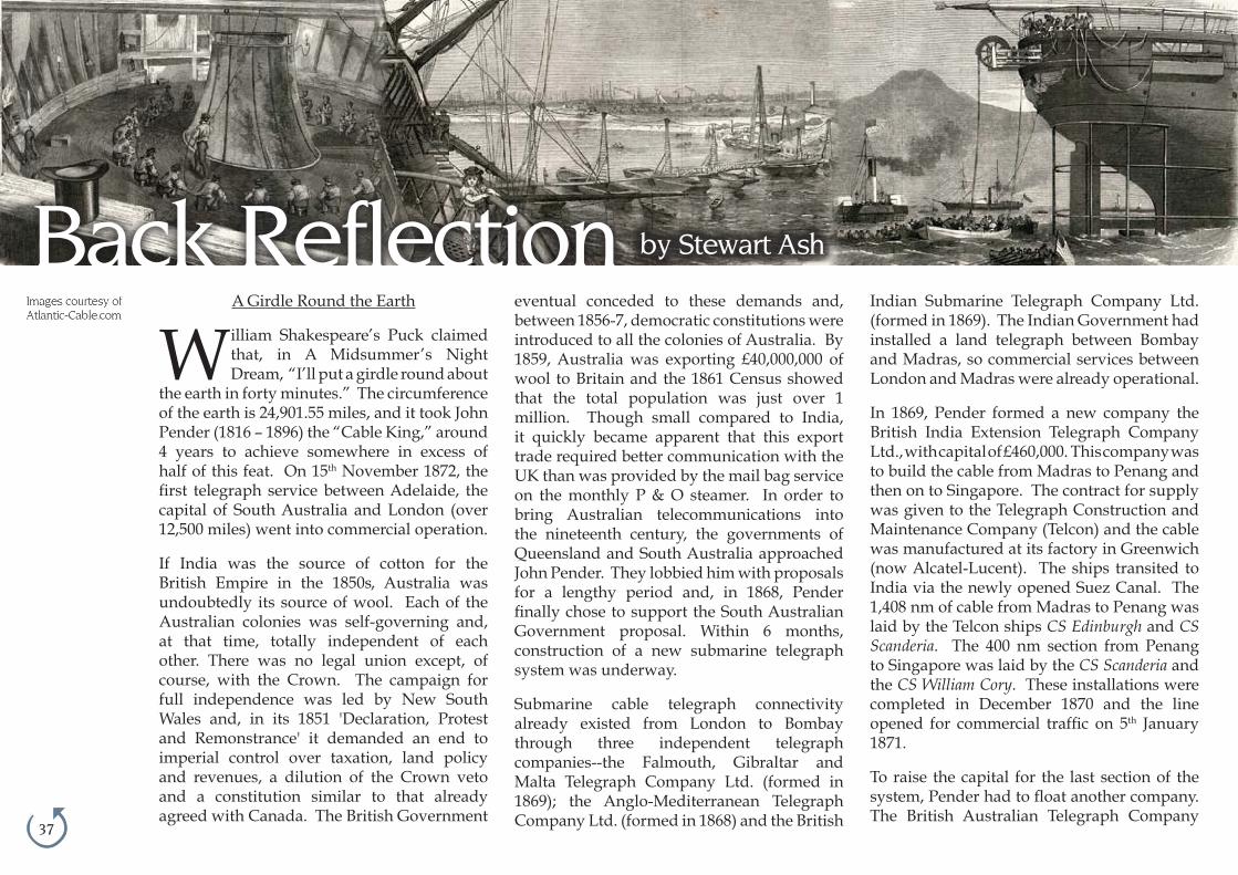
37
Back Reflection by Stewart Ash
A Girdle Round the Earth
William Shakespeare’s Puck claimed that, in A Midsummer’s Night Dream, “I’ll put a girdle round about
the earth in forty minutes.” The circumference of the earth is 24,901.55 miles, and it took John Pender (1816 – 1896) the “Cable King,” around 4 years to achieve somewhere in excess of half of this feat. On 15th November 1872, the first telegraph service between Adelaide, the capital of South Australia and London (over 12,500 miles) went into commercial operation.
If India was the source of cotton for the British Empire in the 1850s, Australia was undoubtedly its source of wool. Each of the Australian colonies was self-governing and, at that time, totally independent of each other. There was no legal union except, of course, with the Crown. The campaign for full independence was led by New South Wales and, in its 1851 'Declaration, Protest and Remonstrance' it demanded an end to imperial control over taxation, land policy and revenues, a dilution of the Crown veto and a constitution similar to that already agreed with Canada. The British Government
eventual conceded to these demands and, between 1856-7, democratic constitutions were introduced to all the colonies of Australia. By 1859, Australia was exporting £40,000,000 of wool to Britain and the 1861 Census showed that the total population was just over 1 million. Though small compared to India, it quickly became apparent that this export trade required better communication with the UK than was provided by the mail bag service on the monthly P & O steamer. In order to bring Australian telecommunications into the nineteenth century, the governments of Queensland and South Australia approached John Pender. They lobbied him with proposals for a lengthy period and, in 1868, Pender finally chose to support the South Australian Government proposal. Within 6 months, construction of a new submarine telegraph system was underway.
Submarine cable telegraph connectivity already existed from London to Bombay through three independent telegraph companies --the Falmouth, Gibraltar and Malta Telegraph Company Ltd. (formed in 1869); the Anglo-Mediterranean Telegraph Company Ltd. (formed in 1868) and the British
Indian Submarine Telegraph Company Ltd. (formed in 1869). The Indian Government had installed a land telegraph between Bombay and Madras, so commercial services between London and Madras were already operational.
In 1869, Pender formed a new company the British India Extension Telegraph Company Ltd., with capital of £460,000. This company was to build the cable from Madras to Penang and then on to Singapore. The contract for supply was given to the Telegraph Construction and Maintenance Company (Telcon) and the cable was manufactured at its factory in Greenwich (now Alcatel-Lucent). The ships transited to India via the newly opened Suez Canal. The 1,408 nm of cable from Madras to Penang was laid by the Telcon ships CS Edinburgh and CS Scanderia. The 400 nm section from Penang to Singapore was laid by the CS Scanderia and the CS William Cory. These installations were completed in December 1870 and the line opened for commercial traffic on 5th January 1871.
To raise the capital for the last section of the system, Pender had to float another company. The British Australian Telegraph Company

38
Ltd. was formed in January 1870 with capital of £660,000. Once again, the supply contract was given to Telcon, and in November 1870 the CS Hibernia laid the 557 nm section from Singapore to Djakarta (then Batavia) on the island of Java. A Dutch owned and operated land telegraph provided the link between Batavia and Banjoewangie on the south east corner of Java. The CS Hibernia returned to the UK, via the Cape of Good Hope, and loaded the final sections of submarine cable. Once again, the cable was manufactured at Telcon’s Greenwich factory. The CS Hibernia departed Greenwich on 3rd August 1871 and transited via the Cape of Good Hope, then, with the CS Edinburgh, installed the final 1,082 nm submarine section from Banjoewangie to Darwin in the Northern Territories.
Pender had agreed with the South Australia Government that he would terminate his submarine cable system, which then stretched from Porthcurno in Cornwall to Darwin, at Port Augusta at the head of the Spencer Gulf north
Brazilian Tel. Co. Ltd. Finally, in 1873, the Globe Telegraph and Trust Co. Ltd. was incorporated. The Globe Trust was formed in order to further spread the risk of cable laying, and shares in the Globe Trust were offered in exchange for shares in the Eastern and associated telegraph companies.
John Pender continued to use this business model for the rest of his life to bring submarine telegraphy to other parts of the world. By his death in 1896, the Eastern and Associated Telegraph Companies Group possessed a virtual monopoly of worldwide communication by telegraph cable, and the companies that he formed went on to be the basis of the modern day Cable & Wireless.
It is often forgotten that John Pender was one of the leading lights of the Atlantic Telegraph, a major investor and the first chairman of Telcon. It was Pender’s business acumen and influence, just as much as Cyrus Field’s enthusiasm and tenacity that brought that famous project to fruition.
If any one person can be said to have achieved Puck’s boast of placing a girdle around the earth, that man surely was John Pender.
38
of Adelaide. This required the Australians to build a 1,973 mile land telegraph between Darwin and Port Augusta. This work was divided into north, south and central sections, each in the hands of different installation teams. The land line from Darwin to Adelaide, and from there to the other principles cities to the south and east, was completed in June 1872. The first test messages were sent the 12,500 miles to from Adelaide to London on 23rd June 1872. However, a cable fault in the submarine section between Darwin and Banjoewangie interrupted commissioning and this was not repaired until 21st October 1872. This is general accepted as the completion date for the “All-sea” telegraph system between Australia and the UK.
In parallel with the Australia project, Pender formed yet another company, the China Submarine Telegraph Company Ltd. This company was formed, in 1869 to install a cable from Singapore to Hong Kong via Saigon.
As can be seen, Pender’s strategy was to spread the significant, short term, risk of laying these cables over a number of independent companies. Once they were established, he set about consolidation. In 1872, the Falmouth, Gibraltar and Malta, the Anglo-Mediterranean and the British Indian Submarine Tel. Co. Ltd, were merged, along with the Marseilles, Algiers and Malta Tel. Co. Ltd. to form the Eastern Telegraph Co. Ltd. Then, in 1873, the British Indian Extension, the British Australian and the China Submarine Tel. Co. Ltd. were merged to form the Eastern Extension, Australasia and China Tel. Co. Ltd. Not content with this, in the same year Pender formed two further companies, the Brazilian Submarine Tel. Co. Ltd and the Western &
Oberon, Titania and Puck with
Fairies Dancing.
From William Shakespeare's
A Midsummer Night's Dream
by William Blake

39
Pacific Telecommunications Council15-18 January 2012Honolulu, HawaiiWebsite
Global Submarine Cable Forum26-28 March 2012London, UKWebsite
ENTELEC15-17 May 2012Houston, Texas USAWebsite
Submarine Networks World Africa 201221-24 May 2012Johannesburg, South AfricaWebsite
Submarine Networks World 20125-7 September 2012SingaporeWebsite
Conferences

40
My dear friend,
I am writing this letter on the opening day of the G20 summit in Cannes, which is taking place in the “palais des festivals,” a building known for hosting the annual Cannes movie festival.
Perhaps this is some kind of message?
It seems to me that these leaders would have done better gathering in a Cathedral, such as the famous one in Chartres. The image of World Heads of State on their knees, burning a candle, singing a psalm or praying to God to bring them some light would have been such a shock that
the people of this planet would have to return the confidence in their leaders that has been lost as of late.
The Greeks, Italians, French and others might make more efforts to accept the proposed cost cutting plans, drastic though they might be. The Americans and the Europeans might recover their morale and creativity. The Arab world might see a little better what they are fighting for. And the emerging countries might have a clearer perception of the landscape into which they are progressing.
We do not need to be told frightening figures every hour. We need our leaders
to give us a vision, an itinerary and a direction.
Where do we all want to go together? What do each of us need to be prepared for?
My friend, to be frank, I have the same feelings concerning our submarine cable community. Our leaders seem to keep their eyes only on their bottom line. I stay tuned in, but I cannot hear any message at all.
Therefore, I am suggesting that the ASN organizers of SubOptic 2013 consider changing the venue of the conference. We have many great and prestigious monasteries in France.
Jean Devos
Letter to a Friend
Jean Devos

41
Through The Looking Glass:The "Perceived" Future of the Submarine Cable
PTC'12
Moderator: Kevin Summers,Editor, Submarine Telecoms Forum,
Panelists:
• Kent Bressie, Partner, Wiltshire & Grannis LLP
• Mike Constable, Director, Business Development, Pacific Fibre
• Ian Douglas, Managing Director, Telecom Business, Global Marine Systems Ltd
• John Pennewell, Director, International Network, AT&T
• Michael Ruddy, Managing Director, Terabit Consulting

42
Ciena www.ciena.com 8
Huawei Marine Networks www.huaweimarine.com 16
Nexans www.nexans.com 31
OFS www.ofsoptics.com 5
WFN Strategies www.wfnstrategies.com 36
Advertisers IndexISSN 1948-3031
Issue Themes:
January: Global Outlook
March: Finance & Legal
May: Subsea Capacity
July: Regional Systems
September: Offshore Energy
November: Subsea Technology
Advertising enquiries:
SALES MANAGERKristian Nielsen
Tel: +1 (703) 444-0845Email: [email protected]
SALES REPRESENTATIVE,EUROPE, AFRICA, MIDDLE EAST
Wilhelm SickingTel: + 49 (0) 201-779861
Email: [email protected]
Copyright © 2011 WFN Strategies
Letter to the editor...
Dear Sir,
I have received the copy of submarine almanac that was sent to me.I can not express my joy when it was delivered to my manager.With all the details, it’s awesome.
Keep it up.
Anthony Nnaji
submarine cable
ALMAnAC2011 edit ion
Su
bm
arin
e C
ab
le A
lman
ac - 20
11 e
ditio
n
21495 Ridgetop C
ircle, Suite 201 | Sterling, VA 20166, U
SA
Compliments of

43What do you think? Click on the Letter To The Editor icon and drop me a line. I’d love to hear from you.
As you've surely heard by now, Steve Jobs, former CEO of Apple, passed away on 5 October. At
the time of his death, he was among the richest Americans and one of the most recognizable business leaders in the world.
I don't want to go into a long history of Jobs' life here, nor do I intend to write yet another eulogy for the man. I know little about him on a personal level, but as a user of his techologies for more than a decade, I would like to say a few things that have come to mind since his death.
There was a time when the leaders of industry were the most famous men (and occasionally women) in the world. When the Titanic sank, nearly 100 years ago, these were the celebrities whose names were passed from mouth to mouth on both sides of the Atlantic. Isidor Straus and John Jacob Astor were the rock stars of their day. I can only think of a handful
of modern entrepeneurs whose names are internationally famous. Bill Gates. Donald Trump. Steve Jobs.
The thing about Jobs that was special, the reason why were talking about him at all, is because he was able to harness his creativity and make something, actually many somethings, that people wanted to buy. The Macintosh computer, the iPod, the iPad, even the MacBook Pro upon which I'm writing this article... all of these are tangible items that have changed the world. Every one of them, from its function to its asthetics, began as an idea in the mind of Mr. Jobs.
Ideas are worthless. The only thing that matters is the execution of an idea.
I talk to aspiring writers all the time, and many of them are filled to the brim with ideas that, if executed properly, could turn them into the next Stephen King
or J.K. Rowling. But their ideas alone, incomplete, are completely without value.
It is, of course, extremly difficult to execute an idea. Many creative people suffer from a lack of discipline. It is the discipline that allows them to turn their ideas into iPhones. Without discipline, Steve Jobs would have been just another dreamer, but because of his work ethic, he was able to throw a hammer through the TV screen of obscurity and set the bar for the rest of us "creative types."
by Kevin G. Summers