Serge Gruzinski and Nathan Wachtel, Cultural Interbreedings Constituting the Majority as a Minority
I .
9 NEGATIVE CYCLOTRON RESONANCE A B S O R P T I O N b
6 Jonathan M. Wachtel 4
A Dissertation Presented to the Faculty of
the Graduate School oflYale University 3 in Candidacy f o r the Degree of
Doctor of Philosophy

Abstract
The kinetic theory of waves in an infinite plasma in a
uniform, constant magnetic field predicts that radiation near the
cyclotron frequency in a sufficiently non-thermal plasma may
grow in time, One effect which can cause such growth or negative
cyclotron resonance absorption of radiation which propagates
perpendicular to the magnetic field direction is the relativistic
energy dependence of the electron's mass. Another is the energy
dependence of the electron-atom collision cross section for low
energy electrons in a neutral gas background. The cyclotron
resonance absorption of microwave energy by monoenergetic electrons
which drift through a cavity resonator has been measured in order
to verify these predictions. In each case the observed absorption
spectra are similar to those calculated in a perturbation theo-
retical solution of the Boltzmann equation treating the cyclotron
resonance interaction between the electron beam and the bounded
standing wave fields of the cavity resonator. An experiment
which exhibits the radiative response in time of a weakly
relativistic, monoenergetic electron ensemble to a short pulse
of cyclotron resonance radiation is also described. The radiation
calculated in an exact solution of the Boltzmann equation is
found to occur in repetitive bursts of diminishing amplitude
following the stimulating pulse, Experiment and theory are
observed to be in qualitative agreement.
ii
Acknowledgment
This thesis would not be complete without an expression
of my indebtedness to Professor Jay L. Hirshfield for four
years of personal tutelage and tolerance.
iii

Table of Contents
Page
Abstract
Acknowledgement
List of Illustration8
I. Introduction
ii
iii
vi
1
1. Preliminary Remarks 1
2 . The Dispersion Relation for Perpendicular Propagation in an Infinite Plasma in a Magnetic
Field 4
3. Negative Cyclotron Resonance Absorption in an
Infinite Plasma 15
4. Negative Cyclotron Resonance Absorption by Weakly Relativistic, Monoenergetic Electrons 18
5. Negative Cyclotron Resonance Absorption by Slow, Monoenergetic Electrons Due to Collisions 20
11. Negative Cyclotron Resonance Absorption by a Weakly
Relativistic Electron Beam 23
1. Formulation of the Experimental Method 23
2. The Struoture and Operation of the Apparatus 25
3. The Microwave Spectrometer 30
4. The Measured Absorption and Oscillation Spectra 32
5. A Theoretical Calculation for the Observed Cyclotron Resonance Interaction 35
111. Pulse Stimulated Cyclotron Radiation from Weakly Relativistic Electrons
1, The Response of Monoenergetic Electrons to a Pulse of Cyclotron Resonance Radiation
iv
49
49
Page
2. A Kinetic Theory Calculation of the Radiation Envelope 5 1
3. The Experimental Method 58
4. The Experimental Observations 62
IV. Cyclotron Resonance Absorption by Low Energy Electrons Elastically Scattered in a Neutral Gas Background
1. General Remarks
2. Measurements of the Absorption Spectrum
3. Calculation of the Cyclotron Resonance Absorption Spectrum
References
65
65
68
72
76
V

List of Illustrations
Figure Number
1.
2.
3.
4.
5 .
6.
7.
8,
9.
10.
11
Caption
Cyclotron resonance absorption spectra for weakly relativistic monoenergetic electrons for various values of p = (-no/vc) (c/mc2).
Cyclotron resonance absorption spectra for non- relativistic electrons in a neutral gas back- ground for various positive values of a 5 Pvc'(P)/vc(P).
Cyclotron resonance absorption spectra for non- relativistic electrons in a neutral gas back- ground for various negative values of a = ~v~l(p>/v~(p).
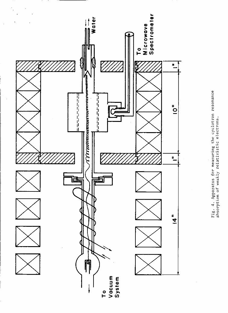
Apparatus for measuring the cyclotron resonance absorption of weakly relativistic electrons.
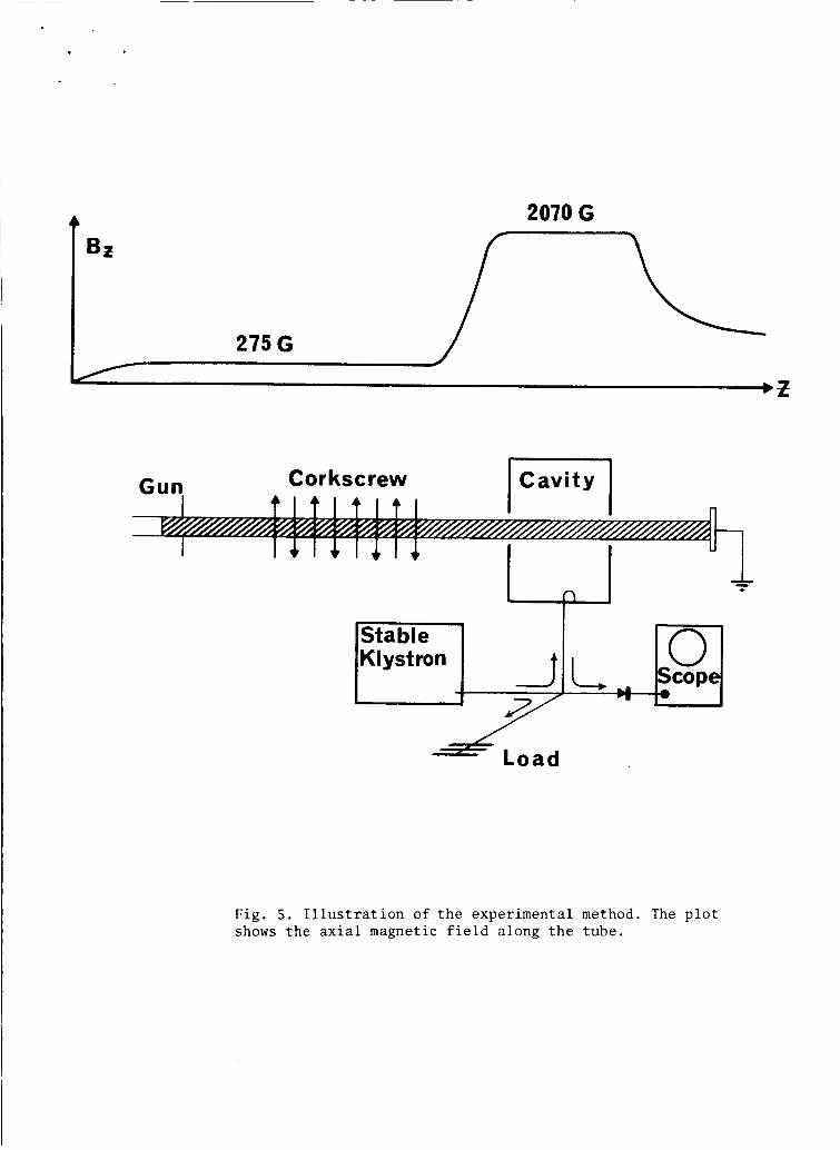
Illustration of the experimental method. The plot shows the axial magnetic field along the tube.
sorption spectrum for 5 keV electrons. (b Magnetic Ab field separation between the two resonances such as in ( a ) , but as a function of electron energy.
Oscillation spectra for various settings of the corkscrew magnetic field strength. The total csthode current is 50 milliamperes and the current indioated ia the colleotor current, The total frequency sweep is 2 Mc/seo.
Follows Page
Coordinate system for the integration of the linearized Boltzmann equation along the un- perturbed orbit of an electron.
The resonance function G(x) = [COS(XX/~)/(~-X~)]~,
The shape of the absorption spectrum predicted by Eq, (74) for .$ = w/K,,c = 3 and for various values of p = vL /v,,c.
Illustration of the experimental method for observing pulse stimulated cyclotron radiation. The plot shows the axial magnetic field along the tube.
20
22
22
27
32
33
35
40
45
47
58
vi

12.
13
14.
1 5 . 16.
17
18.
19.
20.
21.
22.
23.
(a) The measured radiation intensity for 1.4 keV electrons as a function of E the excitation field strength. E is approximately 4 V/cm at the Zirst peak. (b) The theoretical prediction IP - J1 (t/T). 62
Illustration of the experimental method for measuring the cyclotron resonance absorption spectrum of slow electrons in a neutral gas background. The plot shows the axial magnetic field along the tube. 69
Cyclotron resonance absorption spectra for 7 eV electrons in Argon. 70
Cyclotron resonance absorption spectra for 9 eV electrons in Argon. 70
Cyclotron resonance absorption spectra for 10 eV electrons in Argon. 70
Cyclotron resonance absorption spectra for 12 eV electrons in Argon. 70
Cyclotron resonance absorption spectra for 6.5 eV electrons in Krypton. 70
Cyclotron resonance absorption spectra for 7 eV electrons in Krypton. 70
Cyclotron resonance absorption spectra for 7.5 eV electrons in Krypton. 70
Cyclotron resonance absorption spectra for 10 eV electrons in Krypton. 70
Cyclotron resonance absorption spectra for 8 eV electrons in Helium. 70
Cyclotron resonance absorption spectra for 9.5 eV electrons in Helium. 70
vii
1
1.
I. Introduction
Preliminary Remarks
In the early work on the dispersion and absorption of
electromagnetic radiation by dielectrics, the medium was often
considered to consist of a collection of fixed, microscopic.
classical oscillators which reradiated when driven by time
varying electromagnetic fields. For some time thereafter
classical models were forced out of style by more successful
quantum mechanical treatments. The interaction of a system of
free charged particles with electromagnetic radiation, a problem
which in the low particle density limit is quite accurately
described in classical terms, was largely ignored. Recent
activity in the field of plasma physics, however, has yielded
solutions to a variety of problems regarding the electromagnetic
behavior of free charged particle systems. It is to the experi-
mental verification of predictions concerning one class of such
interactions that the research to be described here has been
directed . The interactions in this class fall under the general heading
of cyclotron resonance phenomena. Cyclotron resonance occurs
when a charged particle executing circular (or nearly circular)
motion in a constant magnetic field is coupled strongly to
radiation fields that oscillate at a frequency near the gyration
frequency of the particle motion. Strong coupling can also occur
at multiples of the gyration frequency. Each charged particle
can be considered as one of many little current oscillators whose

2
~~ ~
amplitudes and phases as well as positions are distributed
according to a distribution function which describes the density
of particles in position and momentum space.
The cyclotron resonance phenomena considered in this work
pertain only to the coupling between radiation fields and
electrons which obey single particle classical dynamics under the
influence of a uniform constant magnetic field and the electric
and magnetic radiation fields. The medium is tacitly assumed
to be uncharged. Physically, a positive charge neutralizing
background that does not interact with the radiation fields is
imagined to coexist with the electrons.
The distribution function f(;,l,t) which specified a
statistical knowledge of the electron motion is the normalized
electron density in a single particle phase space. It obeys
the Boltzmann equation
The collisions made by electrons of charge e, mass m, velocity IT,
momentum 2 and position 2 are accounted for in the collision
term on the right. The fields obey Maxwell's equations.
Exhaustive theoretical studies of the interaction of small
amplitude radiation fields with this type of electron plasma
have been accomplished in recent years. Methods for classifying
the various possible modes of radiation and for obtaining their
dispersion relations have been developed.
circumstances the dispersion relation for a particular type of
Under certain
3
radiation field predicts that the wave will grow in time.
least two such possibilities exist for radiation near the gyro-
frequency of the plasma electrons. The first arises in connection
with the anharmonic nature of the motion of a relativistic
electron in a magnetic field, and the second is predicted for
plasmas consisting of electrons that collide with neutral atoms
if the collision frequency is sufficiently energy dependent.
Such negative absorption phenomena will only occur in non-equilibrium
plasmas. *2
functions in the experiments which comprise this work has
therefore been of fundamental concern.
At
The generation of non-equilibrium distribution
In this chapter the simultaneous solution of the Boltzmann
equation and Maxwell's equations using a method introduced by
Bernstein? t o obtain a general dispersion relation for electro-
magnetic wave propagation in unbounded plasmas will be summarized.
The calculation is well known and has appeared in recent texts
on plasma physics. 4 s 5 The dispersion relation will be specialized
to give the growth or damping rates due to the cyclotron resonance
interaotion.
The original part of this work begins with the second chapter
where an experiment which exhibits negative cyclotron resonance
absorption by relativistic electrons is described. The collisional
effect is studied in the fourth chapter. More precise theories
for the relativistic and collisional negative cyclotron resonance
absorption phenomena that are experimentally studied are also
offered. In the third chapter an experiment which exhibits the
radiative response of a monoenergetic, relativistic ensemble of
4
electrons to a pulse of radiation at cyclotron resonance is
described. The experiment could be considered noteworthy
because of its illuminating relation with respect to the
relativistic negative absorption mechanism and because an exact
(non-perturbation) solution of the Boltzmann equation which
describes it has been obtained.
2 . The Dispersion Relation for Perpendicular Propagation in an Infinite Plasma in a Magnetic Field
In order t o introduce these negative cyclotron resonance
absorption phenomena the theory f o r wave propagation in an
unbounded, uniform electron plasma in a constant uniform magnetic
field will be reviewed. The general dispersion relation for
sinusoidal plane wave modes characterized by the wave vector
- k and frequency w will be specialized f o r waves which propagate
perpendicular to the direction of the magnetic field E&,. A class ,
1 of cyclotron resonance interactions that are associated with I
doppler shifts due to electron motion along go are thereby
eliminated from consideration. These interactions have been
studied theoretically by Weibel and Harris.? They are not
basic to the experiments described here,
6
Several approximations are made in reducing the dispersion I I
relation to the case of interest. The plasma is considered to be
so tenuous that collective effects may be ignored and the damping
or growth rates considered to be small. Thus the electrons are
independent current oscillators which interact with the fields
but not with each other. In the limit of vanishing electron
5
density the wave reduces to the mode which propagates across go
with its electric field polarized normal to B . The theory will
be shown to suggest the existence of the two negative cyclotron
resonance absorption phenomena for this mode in low density
plasmas. Negative absorption persists even for plasmas whose
distribution functions are isotropic in momentum space.
-0
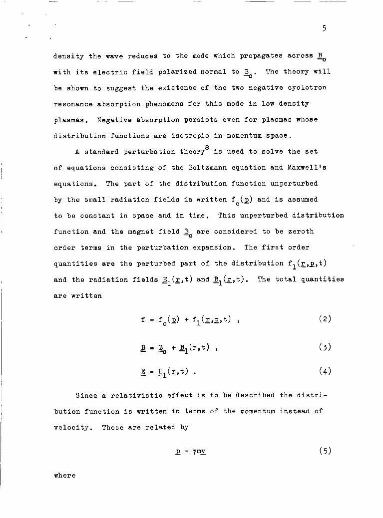
A standard perturbation theory' is used to solve the set
of equations consisting of the Boltzmann equation and Maxwell's
equations. The part of the distribution function unperturbed
by the small radiation fields is written fo(x) and is assumed
to be constant in space and in time. This unperturbed distribution
function and the magnet field % are considered to be zeroth order terms in the perturbation expansion. The first order
quantities are the perturbed part of the distribution fl(x,x, t) and the radiation fields E1(Z,t) and g1(-r,t). are written
The total quantities
Since a relativistic effect is to be described the distri-
bution function is written in terms of the momentum instead of
velocity. These are related by
E = Ymv ( 5 )
where
6
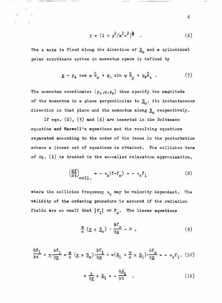
2 2 2 * y = ( l + p / m c ) . The 2; axis is fixed along the direction of and a cylindrical
polar coordinate system in momentum space is defined by
(7 ) A A A 2 = pI cos cp e + pL sin cp ey + pilez . X
The momentum coordinates (pL,~,pI1) thus specify the magnitude
of the momentum in a plane perpendicular to B its instantaneous
direction in that plane and the momentum along B respectively.
-0’
-0
If eqs. (2), ( 3 ) and (4) are inserted in the Boltzmann
equation and Maxwell’s equations and the resulting equations
separated according to the order of the terms in the perturbation
scheme a linear set of equations is obtained. The collision term
o f Eq. (1) is treated in the so-called relaxation approximation,
e9coll = - vc(f-fo) = - vcf 1
where the collision frequency vc may be velocity dependent.
validity of the ordering procedure is assured if the radiation
fields are so small that lfll << fo.
The
The linear equations
7
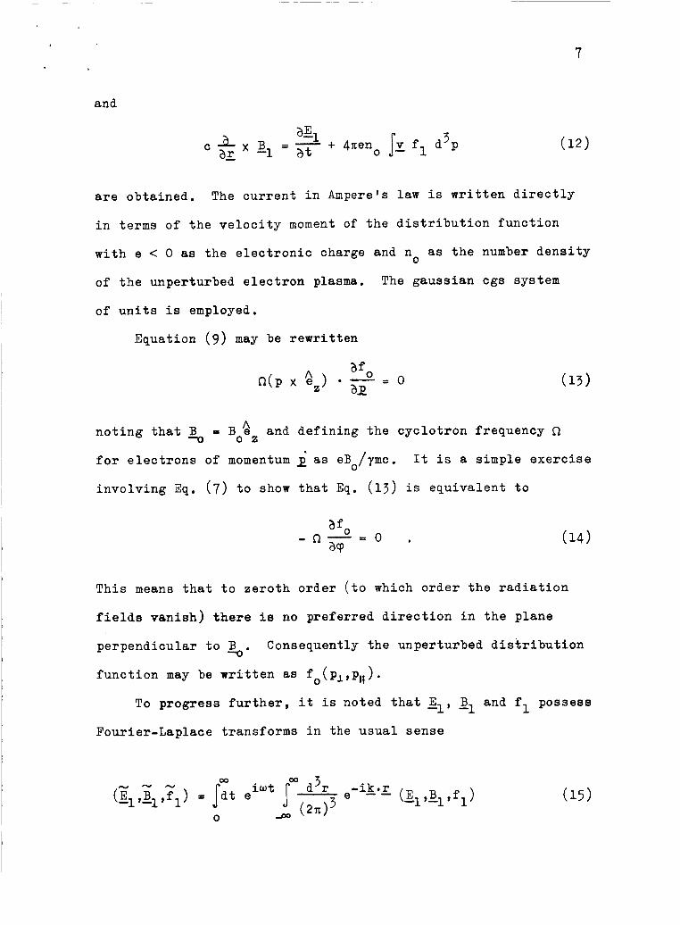
and
are obtained. The current in Ampere's law is written directly
in terms of the velocity moment of the distribution function
with e < 0 as the electronic charge and no as the number density
of the unperturbed electron plasma. The gaussian cgs system
of units is employed.
Equation (9 ) may be rewritten
A 0 2
noting that = B e and defining the cyclotron frequency R
for electrons of momentum
involving Eq. (7) to show that Eq. (13) is equivalent to
as eBo/ymc. It is a simple exercise
This means that to zeroth order (to which order the radiation
field6 vanish) there is no preferred direction in the plane
perpendicular to s. function may be written as f (pL,pll).
Consequently the unperturbed distribution
0
To progress further, it is noted that sl, B and f possess -1 1 Fourier-Laplace transforms in the usual sense
8
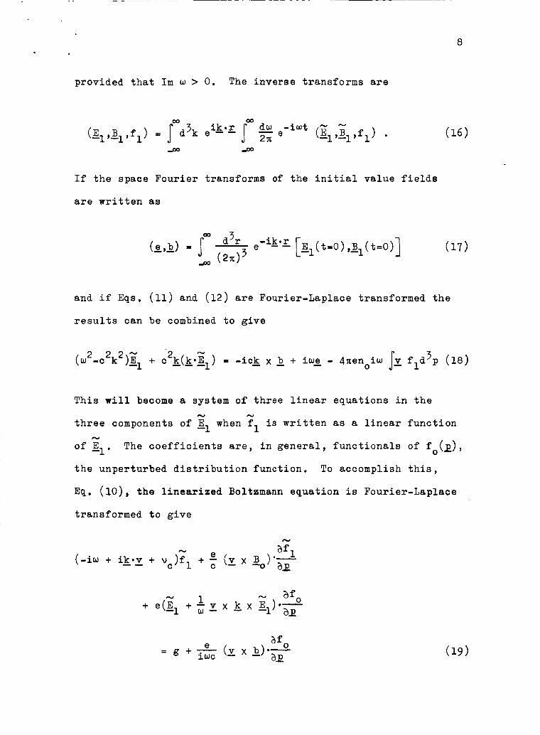
provided that Im w > 0. The inverse transforms are
If the space Fourier transforms of the initial value fields
are written as
and if Eqs. (11) and (12) are Fourier-Laplace transformed the
results can be combined to give
3 N 2 2 2 - 2 ( w -c k )E1 + c &(&*El) = -ic& x b + iwg - 4nenoiw fld p (18)
This will become a system of three linear equations in the
three components of El when f 1 of El. the unperturbed distribution function. To accomplish this,
N N
is written as a linear function cy
The coefficients are, in general, functionals of fo(p),
Eq. (lo), the linesriaed Bo1tz;mann equation is Fourier-Laplace
transformed t o give
N
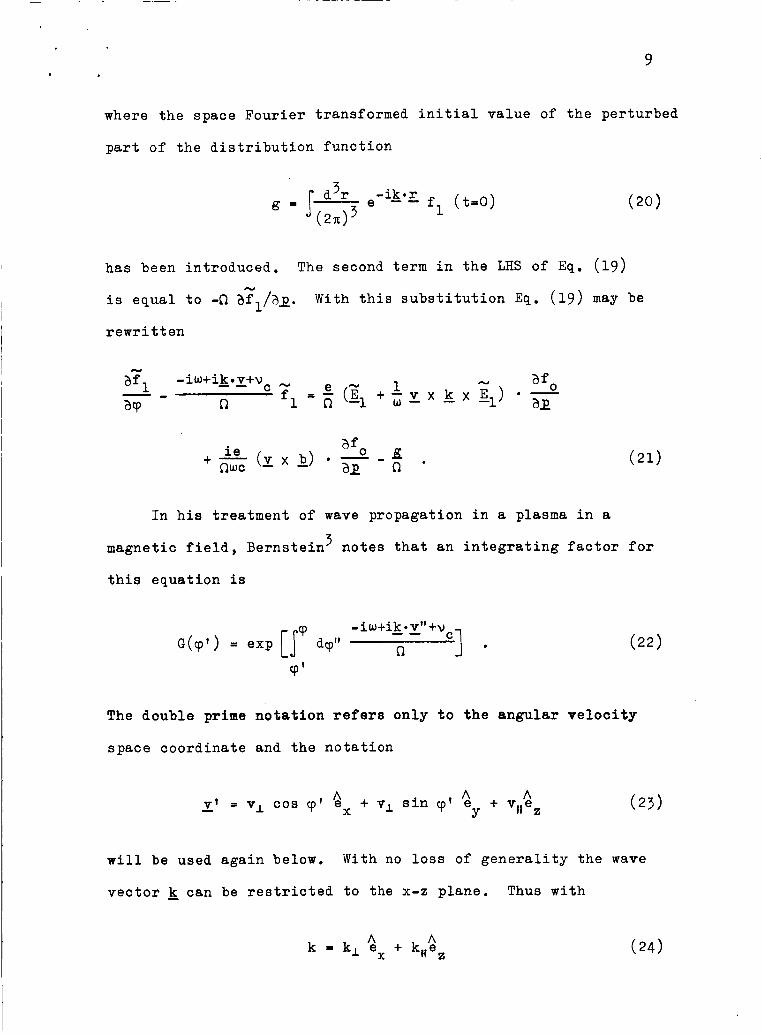
9
where the space Fourier transformed initial value of the perturbed
part of the distribution function
has been introduced.
is equal to -n afl/i)i.
rewritten
The second term in the LHS of Eq. ( 1 9 ) cy
With this substitution Eq. ( 1 9 ) may be
In his treatment of wave propagation in a plasma in a
magnetic field, Bernstein notes that an integrating factor for
this equation is
3
The double prime notation refers only to the angular velocity
space coordinate and the notation
will be used again below. With no loss of generality the wave
vector k can be restricted to the x--8 plane. Thus with
A A k = k, e + kHez X

10
the integration in Eq. ( 2 2 ) is readily performed to give for
the integrating factor
The solution of Eq, (21) is
- t3] ie af 0 + - ( T x b ) * - WC a?'
For electrons R < 0, and since Im w > 0 the lower limit of
integration is chosen to be minus infinity so that the integral
converges. The transformed, perturbed distribution function fl
is now inserted into Eq. (18) to obtain
N
where 1, defined by
contains all the initial value terms.

11
Equation ( 2 7 ) may be expressed in matrix form as
N
which can be inverted to give
where qC is the matrix of cofactors of E.
The elements of & are obtained in terms of f (pI,p,,) by
performing the angular integrations in the LHS of Eq. (27) .
integration over 9’ is indicated and that over cp is contained
- - - 0
The
m QJ 2x in the momentum space integration (d 3 p ( . . .) = Ip,dp, J dp,, J dy(. . .).
0 go 0
A complicated series involving Bessel functions of argument
k,vI/Q is generated.
the reader is referred to Ref. 5 which contains the treatment
For details concerning these integrations
being summarized here,
In principle one can insert Eq. (30) into the Fourier-Laplace
inversion formula Eq. (16) to obtain an expression for gl(;,t) f o r all t > 0. However, difficulties involved in such a straight-
forward approach to the initial value problem are made obvious
when the analytic properties of the components of & and of I are examined. Pathological choices of the initial perturbed
-
distribution function or initial fields can lead to a variety
of singularities in the numerator of Eq. On the other hand
the poles which occur when the denominator vanishes lend themselves
to a simple interpretation. The values of w and of k which cause the denominator of Eq. ( 3 0 ) to vanish are considered to define
the normal modes for wave propagation in the plasma medium.
1 2
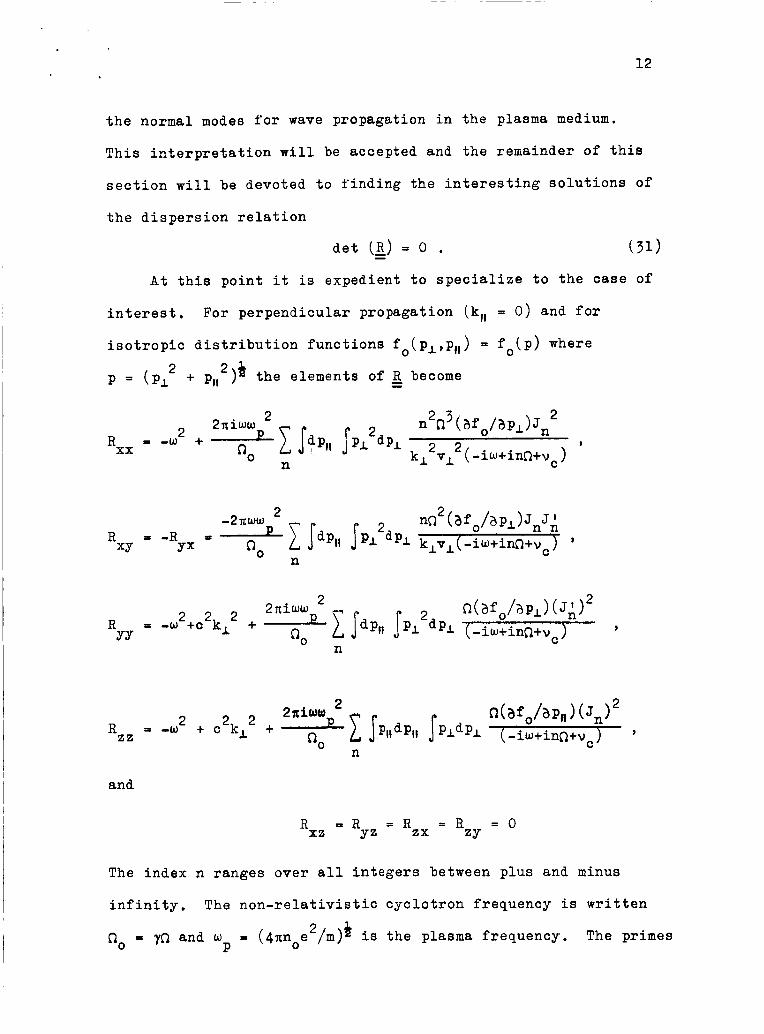
This interpretation will be accepted and the remainder of this
section will be devoted to finding the interesting solutions of
the dispersion relation
A t this point it is expedient t o specialize to the case of
For perpendicular propagation (kit = 0) and for interest.
isotropic distribution functions f (p,,pa) = fo(p) where
p = (p, + pH2)* the elements of 0
2 become
and
R = R = Rzx = R X Z YZ ZY = o
The index n ranges over all integers between plus and minus
infinity. The non-relativistic cyclotron frequency is written
62, = y Q and w = (4nnoe /m)* is the plasma frequency. The primes 2 P
upon the Bessel functions indicate a derivative with respect to
the argument which in all cases is kLvL/0.
A solution of Eq. (31) is sought for frequencies near the
cyclotron frequency that describes transverse waves propagating
across B These modes should reduce to the free space limit of
electric field polarization normal to % as the plasma density decreases to zero. For tenuous plasmas (u C< w ) the non-
vanishing off-diagonal elements R and R may be neglected
and in this approximation the solution R P 0 corresponds to
such waves. The mode characterized by 1 El is commonly referred to as the extraordinary wave. The other solutions
-0.
2 P
XY YX
N YY
= 0 and Rzz = 0 correspond t o longitudinal plasma oscillations Rxx and to a wave whose electric field is oriented along B
respectively. -0
Another approximation is made by expanding the Bessel functions
in powers of the small argument and retaining only lowest order
terms. The argument kLvl/R is of the order of the ratio of the
radius of the cyclotron orbit of an electron to the wavelength
of the radiation. Only the n - fl terms in the sum will be zeroth order in k,v,/R.
and the electrons will be strongest near the cyclotron frequency
and weak at cyclotron harmonic frequencies. Cyclotron harmonic
interactions originate with the anharmonic nature of the force
on an electron due to the finite extent of its cyclotron orbit
in a sinusoidally space dependent radiation field. The small
argument klvL/R is also of the order of vL/c for waves near the
cyclotron frequency R. Thus for w - -R only the n = -1 term
Therefore the interaction between the field8
14
need be considered and the dispersion relation for the extraordinary
wave in an isotropic, tenuous, weakly relativistic electron plasma
is simply
2 It is noted that the last term in the LHS is smaller than w
for consistency with the neglect of R
to ignoring collective polarization effects in the medium. The
picture of the medium as being composed of independent microscopic
current oscillators is thereby obtained.
and R which amounted XY YX
Since the distribution function fo( pL,p,,) has been assumed
isotropic and since the cyclotron frequency 0 or the collision
frequency depends only upon the magnitude p of the momentum,
Eq. (32) will be written in terms of p alone.
variables of integration (p,e) via pL = p cos 0 and p,, = p sin 6 ,
and noting that
Introducing new
'Eq. (32) becomes
or

3 . ITeaative Cyclotron Resonance Absorption in an Infinite Plasma
The dispersion relation can be solved approximately for the
small growth or damping constant Im w; but before a solution is
indicated the validity of the dispersion relation for negative
values of Im w must be established. It will be remembered that
the Laplace transforms were defined only for positive Im w. The
dispersion relation must, therefore, be analytically continued
into the lower half w-plane in order to define modes that decay
in time. The necessity for the analytic continuation of the
dispersion relation was first pointed out by Landau” for the
case of damped electrostatic waves in a collisionless plasma.
Enlightened discussions of this topic appear in more recent
publications. 11
The dispersion relations for the normal modes of electro-
magnetic wave propagation in collisionless plasmas are difficult
to interpret because the integrals involved have singular
integrands.
At some particular momentum p the electron gyrofrequency and the
wave frequency are equal, and for undamped waves the denominator
of the integrand vanishes. The procedure introduced by Landau
is to interpret the integral in the Cauchy principal value sense
for vanishingly small positive Im w, The analytic continuation
is then straightforward. A dispersion relation is chosen for
Im w < 0 that converges to the same expression as Im w goes to
zero from below. However, the complicated dependence of the
cyclotron frequency on momentum makes the mathematics involved
in the present situation more difficult. The approach to be used
Eq. (34) is an example if vc is set equal to zero.
16
here will be to retain the collision frequency v in the dispersion
relation whence for IIm w1 < v, the integrand in Eq. (34) is non-
singular for all real p. Thus for small Im w the dispersion
relation of Eq. (34) is its own analytic continuation into the
C
”
lower half w-plane and damped modes are well defined.
As a first approximation to the solution of the dispersion
relation Eq. (34) the effect of the plasma is neglected and the
free space result w = ck, is obtained. It is the zeroth order
term in an expansion of the dispersion relation in powers of w
as may be verified by the following procedure.
2 P
Equation (34)
is abbreviated D(w,k,) = 0 and is expanded about w = ck, to
obtain
or
Inserting
the imaginary part gives for the growth or damping rate correct
to first order in w
D(w,kl) from Eq. (34) into Eq. (36) and extracting
2 P
An alternative expression that follows after an integration by

parts is
For low energy non-relativistic electrons which suffer
collisions at the same frequency Eq. (38) can be integrated
trivially for arbitrary fo(p) to give the Lorentzian shaped
absorption spectrum. In this case the wave is always damped.
On the other hand if the collision frequency depends upon the
energy of the electrons the form of the distribution function
is crucial and growth is even possible.
that reveals growth for sharply peaked distribution functions
is offered later in this chapter.
A more detailed analysis
For distribution functions which represent a broad range of
relativistic momenta Eq. (37) may be used to obtain a simple result
for Im w. The collision frequency is considered to be a constant.
If the wave frequency ckl and the non-relativistic cyclotron
frequency fl are fixed, the integrand may contain a sharply
peaked resonance at some particular momentum p.
for Im w equivalent to Eq. (37) is
0
An expression
vC c1 2 2 '
afO XU 2 0 3
3zz0 Im w 2:- dp P3 ap
(ckL+ha) + vc 0
( 3 9 )
If fo(p) is broad with respect t o the width in p of
2]-1, then Eq. ( 3 9 ) may be symbolically written 2 C(ck,+d + vc

Physically this states that only a narrow range of momenta
satisfy the cyclotron resonance condition and that those resonant
electrons cause growth or damping of the wave according to the
sign of the slope of the distribution function at that value of
momentum. Clearly the wave is damped if afo/ap is negative and
it grows if afo/ap is positive.
of the quantum mechanical requirement that higher energy states
be overpopulated for maser action to occur.
This is the classical analog
In the following sections the absorption spectra for narrow
distribution functions will be discussed.
4. Negative Cyclotron Resonance Absorption by Weakly Relativistic, Monoenergetic Electrons
In anticipation of the fact that the experiments to be
described later have been performed upon monoenergetic electron
beams Eq. ( 3 8 ) will be evaluated for the monoenergetic, isotropic
distribution function
fo(PI,P,,) = - 2 6(p-P) . 4xp
An electron beam is not, however,) isotropic in momentum space.
Albeit, the absorption line shapes observed in the experiments
will subsequently be shown to be but slightly modified by the
anisotropic nature of the unperturbed distribution function.

Recalling the transformation pI = p cos 0 and p,, = p sin 8 2 and noting that p = (pl + P,,~)* it is an easy matter to show
that the distribution function of Eq. (41) is correctly normalized,
The calculation follows:
m 2 1 cos 0 d0 p dp 7 ~(P-P) = 1
n/2 - 2a J 4xp -a/2 0
Inserting this delta function distribution into Eq. (38) and
integrating one obtains for the damping or growth constant in
a weakly relativistic plasma
2 2 2 The approximation 0 2: no(l - p /2m c ) has been used.
ation and extraction of the imaginary part leads to the
ex pr e s s ion
Differenti-
Imw2:- (43)
2 where E = P /2m is the non-relativistic expression for the energy,
The frequency deviation from exact cyclotron resonance in units
of the collision frequency is
2 2 6 = (-~o/vc)(l+ck,/~o-~/mc ) and (3 = (-C20/vc>(~/mc ) .
20
2 Terms have been kept to first order in e/mc . in a weakly relativistic plasma the factor 5e/mc2 in Eq. (43)
is but a small correction. Neglecting it gives the cyclotron
resonance absorption line shape in terms of the frequency variable
6 and the parameter p alone. Thus Eq. (43) becomes
For vc << no
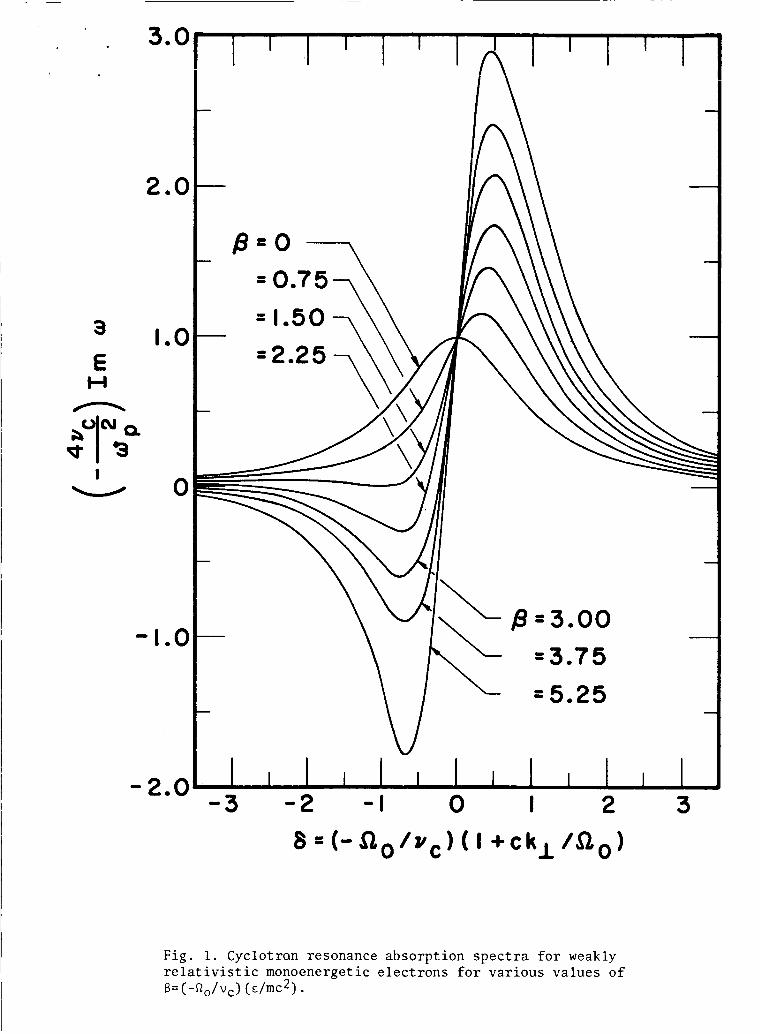
Im w Z l + 4vc - - 1 + 6* (1+6*)* '
2 W P
(44)
This result is plotted in Fig. 1. Negative absorption is observed
to occur for magnetic field strengths lower than the cyclotron
resonance value if p > 3/2.
amount of relativistic phase focusing that can occur in the
The quantity (3 is a measure of the
-I momentum space plane normal to 3 in a collision time vc phase focusing is a result of the energy dependence of the electron's
gyrofrequencies. It produces currents associated with the second
term in the RHS of Eq. (44) which add to or cancel those associated
with the first (Lorentzian shaped) term to give respectively
enhanced absorption or negative absorption of the wave. The
predicted absorption lineshape in Fig. 1 will be compared with
experimental results. An experiment which explicitly illustrates
the cyclotron orbital phase focusing effect will also be described.
. This
5. Negative Cyclotron Resonance Absorption by Slow, Monoenergetic Electrons Due to Collisions
A class of negative absorption phenomena which owe their
existence to the energy dependence of electron-neutral atom
collision cross sections have often been discussed in the published
3.0
2.0
3
E H n
I W
1.0
0
-1.0
- 2.0
I 1 I I I ‘ A I \ I \
-3 - 2 - I 0 I 2 3
Fig. 1. Cyclotran resonance absorption spectra for weakly relativistic monoenergetic electrons for various values of B= (-fiO/vc) (E/mc2) .
21
literature.12 For the case of cyclotron resonance no definitive
experiments have been performed although some suggestive results
have been obtained. l3
resonance absorption is particularly simple to analyze if the
relaxations1 approximation is applied using an energy dependent
collision frequency. l4
line shapes which resemble those predicted in the simple theoretical
The effect of collisions upon cyclotron
In this research experimental absorption
result below have been obtained.
The most interesting cross section behavior occurs at energies
of a few eV.
in point.
distribution functions given in Eq. (42) may be applied if the
relativistic corrections are neglected and if the collision
frequency is considered to be a function of momentum.
is a smoothly varying function in the neighborhood of the electron
momentum P one can write
Atoms exhibiting the Ramsauer effect” are a case
The growth or damping rate for monoenergetic isotropic
If vc(p)
After differentiation and extraction of the imaginary part the
result
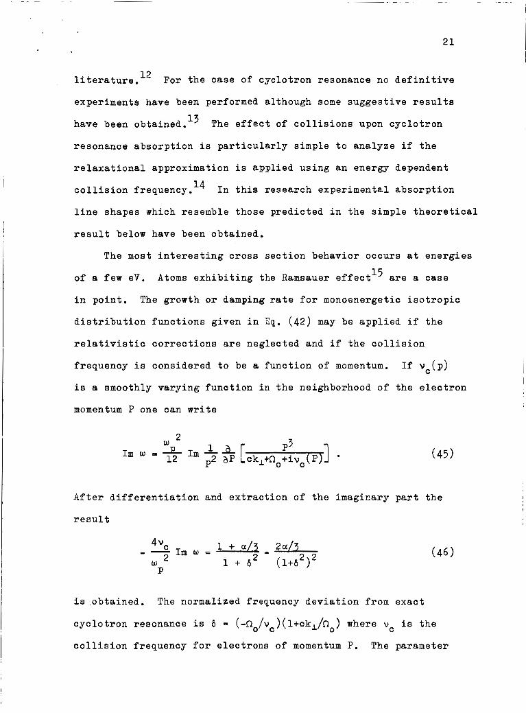
1+(x/3 - 2 d 3 Im w = 4vc - - w 2 1 + 62 (1+62)2 P
is ,obtained. The normalized frequency deviation from exact
cyclotron resonance is 6 - (-~o/vc)(l+ck,/~o) where vc is the
collision frequency for electrons of momentum P. The parameter
22
I(P)/v (P) is a measure of the slope of the collision a = Pvc C
frequency et momentum P. It determines the amount of selective
phase randomization that occurs to produced enhanced or negative
absorption.
in Fig. 2 for several positive values o f the parameter a.
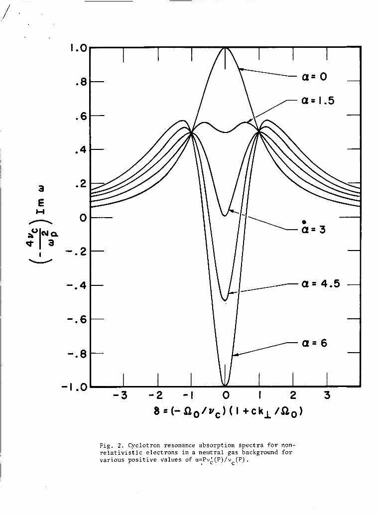
The RHS of Eq. (46) is plotted as a function of 6
Negative absorption at cyclotron resonance is predicted for
a > 3. Negative absorption can also occur for OL < -3 at either
side of cyclotron resonance. This case is illustrated in Fig. 3 .
3 E
n W
I W
I e o
.8
.6
e 4
02
0
- . 2
-. 4
0.6
0.8
- I 00 -3 - 2 - I 0 I 2 3
F i g . 2 . Cyclotron resonance absorpt ion s p e c t r a f o r non- r e l a t i v i s t i c e l ec t rons i n a n e u t r a l gas background €or var ious p o s i t i v e values of a=Pvl(P)/v (P) .
C

3
E n t4
I W
5
4
3
2
I
0
- I
- 2 -3 -2 - 1 0 I 2 3
Fig. 3 . Cyclotron resonance absorp t ion s p e c t r a f o r non- r e l a t i v i s t i c e l ec t rons i n a n e u t r a l gas background €or var ious negat ive values of a=Pvk (P) /vc (P) .
11. Negative Cyclotron Resonance Absorption by a Weakly Relativistic Electrcn &am
1. Formulation of the Experimental Method
Although a general theoretical treatment of wave propagation
in a hot plasma is most easily accomplished by an infinite plane
wave normal mode analysis, certain problems are encountered if
a direct experimental verification of such a theory is attempted.
Experimental cyclotron resonance absorption spectra could be
expected to resemble the results in Figures 1, 2 or 3 only if
the dimensions of the interaction region were many wavelengths
long. If, for example, a reasonable cyclotron resonance magnetic
field strength is of the order of 2000 gauss, cyclotron resonance
occurs at approximately 6000 hlc/sec.
2x/kl would be 5 cm.
meters would be necessary. Alternatively higher magnetic fields
may be contemplated but the difficulty of obtaining stable
monochromatic radiation sources at the correspondingly higher
cyclotron frequencies becomes an annoying factor. Practical
considerations seem to limit the choice of frequency to the
centimeter wavelength microwave range.
The free space wavelength
An apparatus whose dimensions are several
If one were able to generate homogeneous magnetic fields
of the order of a few kilogauss in large regions filled with a
suitable electron plasma, one would still be faced with the
problem of maintaining a propagating electromagnetic wave. The
electromagnet itself would be the primary obstacle. A direct
24
laboratory scale test of the results obtained from a free space
plane wave dispersion relation is clearly not possible.
A logical compromise would be to measure the spatial growth
or decay of bounded plane waves in a plasma filled waveguide
whose axis lies in a direction perpendicular to the magnetic
field. Practical laboratory dimensions would limit the inter-
action length to a few wavelengths and since the growth or
damping rates must be small for the theoretical predictions of
the last chapter to hold, the effect might well be immeasureably
small.
Without pursuing any further the objections to experiments
on propagating waves, the experimental technique used in this
work will be introduced, The electron gas is allowed to drift
along through the bounded standing wave environment of a
microwave cavity. The cavity is excited at the resonant frequency
of a mode chosen so that its electric field lies in a plane
perpendicular to %. fields and the absorption of field energy is measured using a
conventional microwave spectrometer as the uniform magnetic
field is swept through cyclotron resonance.
The electrons interact with the cavity
The electrons must interact with the cavity fields for a
significant number of periods of oscillation. The time interval
that they do spend in the cavity plays the role of the relaxation
time vc O1 found in the plane wave calculation.
for negative absorption to occur, Thus the interaction of the -1 cavity fields with electrons which traverse the cavity in v
seconds and which suffer no collisions is qualitatively similar
It must be large
C
25
to the interaction described in the unbounded plane wave analysis -1 for electrons which suffer collisions every v seconds. C
With the exception of possible transit time effects the
absorption line shape of Fig. 1 should be experimentally observed.
This conclusion is supported by the experimental results and by
a calculation which treats the problem of energy absorption by
electrons in the standing wave environment of a cavity.
The remainder of this chapter is devoted to the relativistic
effect. The experiment will be described in detail and a more
precise theory for the experimental configuration used than the
self consistent field, plane wave analysis will be offered.
2. The Structure and Operation of the Apparatus
The objective of the experimental design was to obtain a
weakly relativis.tic electron beam which would drift slowly in
the direction of a uniform magnetic field while passing through
an evacuated microwave cavity resonator. All but a small fraction
of the electrons' energy would be associated with rotational
motion about magnetic field lines. The cavity was designed to be
coupled to a microwave spectrometer which would measure the
cyclotron resonance absorption of microwave field energy in the
cavity by the electrons.
A device known as a "magnetic corkscrewt'l6 was used to obtain
the desired distribution of electron momenta from an electron
beam. This device transforms momentum of charged particle motion
along a magnetic field into momentum transverse to the field.
It has been used in experimeqts on plasma confinement with moderate

26
success . 17,18 The magneti corkscrew is constructed by 100s
winding a few turns of wire about a tube which contains the
electron beam. A return winding placed between the turns of
lY
the
first carries the current of the first back to its source. Since
the solenoidal currents cancel, no magnetic field parallel to the
axis of the device (at its axis) is generated. A weak transverse
magnetic field is, however, generated because the turns are widely
spaced. The direction of this field rotates periodically along
the axis of the device which is immersed in a uniform magnetic
field with its axis parallel to it. With the turns of the
corkscrew winding spaced so that the pitch of the weak transverse
magnetic field equals the pitch of the helical electron orbit
for a given axial velocity in the strong axial field, the trans-
verse energy of the electron will increase at the expense of its
energy associated with motion parallel to the axial field. No
more'than a fraction of the total energy of an axially streaming
electron beam may be transformed into energy of rotation by a
weak corkscrew magnetic field unless the pitch of the corkscrew
winding is reduced along the tube to compensate for the reduction
in axial velocity. In the corkscrew device used no such
compensation was attempted. I
For electrons which enter the corkscrew with no transverse
velocity v,, and which remain in exact helical resonance with the
perturbing corkscrew field b,, it is shown in Ref. 17 that the
transverse velocity is always perpendicular to the transverse
field. The equation of motion

e - 0 - v x g dt ymc -
-~
27
(47)
may be integrated to give the result I
The integration is along the axis of the corkscrew which coincides
with the directionof theaxial part of 2. The corkscrew used in
the experiments was designed for 5 keV electrons. It was
constructed with a pitch of 5.7 cm per turn and had four turns.
The axial magnetic field for which 5 keV, axially streaming electrons
have the same pitch is 275 gauss.
b, ," 2.6 gauss is necessary for ten percent of the total energy
to become rotational energy. The electrons emerge from the
magnetic corkscrew with nearly the same axial velocity as that
with which they entered.
According to Eq. (48),
Referring to the pictorial rendition of the apparatus in
Fig. 4, the electrons are observed to enter a second region which
contains a very uniform axial magnetic field. Its intensity is
approximately 2070 gauss for cyclotron resonance at 5800 Mc/sec
and near the axis of symmetry of the configuration it is uniform
to within f0.2 gauss. This region is separated from the magnetic
corkscrew region by a one inch thick cold rolled steel plate.
The tube whose outer diameter is 1.05 inches and wall thickness
is 1/16 inch passes through a 2 inch diameter hole bored in the
steel plate. The tube and the hole in the plate are coaxial
with pancake type solenoid windings whichsupport the axial magnetic
1 1 I I c
k o x +Id

28
fields. A similar plate at the far end of the cyclotron resonance
field region helps to maintain the field uniformity.
The electrons which emerge from the corkscrew magnetic field
region execute helical motion about converging magnetic field
lines as they pass through the hole in the steel plate. The field
convergence has the effect of further increasing the rotational
kinetic energy of the electrons at the expense of their energy of
parallel motion. In fact, if the electrons possess a large enough
kinetic energy of rotation before they enter the increasing field
region they are turned around by the converging field. This is
the well known magnetic mirror effect although in this experiment
the effect is not entirely due to the adiabatic invariance of the
orbital magnetic moment. Only near the end of the magnetic mirror
region where the electrons, having lost most of their parallel
energy, execute many periods of cyclotron rotation as they traverse
a length over which the field increases moderately is the familiar
adiabatic condition an accurate description. l9 The dynamics for
the case of a sharply increasing (non-adiabatic) magnetic mirror
is somewhat complicated and has been treated elsewhere. 20
The electrons which enter the cyclotron resonance region
between the steel plates drift slowly in the axial direction,
The small fraction of their total energy of 5 keV that was associated
with the axial drift was varied by changing the current in the
corkscrew winding. A current of 15 amperes was sufficient to
bring the drift velocity to zero at some point in the magnetic
mirror region thus cutting off the beam entirely.
29
Midway between the steel plates the electrons drift through
a microwave cavity resonant at 5800 Mc/sec in the TEOll mode.
The axis of the cavity was parallel to the tube axis and to & so that the electric field of the cavity mode was perpendicular
to go. and parallel to its axis. These served to suppress the TMlll
mode which is frequency degenerate with the desired TEOll mode.
The cavity formed part of the vacuum chamber itself and coupling
was accomplished via a microwave transparent ceramic vacuum
window. An inductive loop coupled the cavity fields to the field
of a coaxial transmission line that passed through a second but
smaller (7/4 inch diameter) hole in the second steel plate.
electron current was collected and returned to the 5 keV potential
source by an insulated water cooled collector.
Rods were placed in the cavity which were displaced from
The
The tube was constructed entirely of type 304 non-magnetic
stainless steel except for the cavity whose walls were of OFHC
copper. It was sectioned and joined utilizing commercially
available vacuum flanges which form seals by compressing copper
gaskets. All structural joints were either brazed in vacuum or
welded in an inert gas atmosphere in accordance with recommended
high vacuum procedures. 21
A chamber placed immediately before the magnetic corkscrew
housed the electron gun. The cathode used was a barium compound
impregnated, circular tungsten disc mounted in a molybdenum sleeve.
The disc surface faced the magnetic corkscrew and was concentric
with the tube.
molybdenum sleeve behind the emitting surface) were supported by
The cathode and heater (which rested in the
wires which passed through a vacuum flange via ceramic insulators.
The flange was sealed to the mating chamber flange surface by
compressing an annealed gold wire (.O25 inch) rcO" ring.
cathode to which one heater lead was connected floated at a
negative potential with respect t o the grounded tube body. The
heater current was reduced from i ts maximum of 10 amperes to
afford an independent control over the total current in the tube.
The
The tube was connected at the electron gun end to a high
vacuum system which. maintained a pressure of 2 x
baking for 24 hours at 4 0 O o C . The vacuum system was mounted on
a heavy steel cart which rolled on tracks that were parallel to
the axis of the solenoid magnet. The tube was thus rolled into
the magnet which had a seven inch bore. The cavity, however,
could not pass through the two inch diameter holes bored in the
steel plates. Consequently the plates were constructed with a
seven inch wide removable section. The top half of the removable
section could be lifted up and out like a gate in a castle wall
at the head of a drawbridge. The bottom semi-circular half could
then be rotated around the tube and lifted out. Some dimensions
are indicated in Fig. 4 although the drawing is not to scale.
It will also be noted that only two of the four turns of the
corkscrew winding are indicated.
mm H g after
3 . The Microwave Spectrometer
The resonant frequency of the cavity is found by tuning the
stabilized klystron used as the source of microwave power until
the power reflected at the single coupling port is minimized.

If, however, the cavity contains electrons gyrating in a magnetic
field for which the cyclotron frequency is near the resonant
frequency of the driven cavity mode, then the response of the
system is more complicated because the electron gas is highly
dispersive and absorptive for frequencies near cyclotron resonance.
Fortunately much attention has been given to the problem of
a simple resonant circuit which interacts with a collection of
absorbing oscillators via its own oscillating fields.
problem is central to the interpretation of most experiments in
the areas of radio frequency and microwave spectroscopy, In
practice it consists of interpreting the measured change in the
response of a resonator excited at a fixed frequency (near its
own resonance) as a magnetic field is varied in the neighborhood
of the value which equalizes the excitation frequency and the
frequency of the classical or quantum oscillators which constitute
the absorbing medium. In their early work on nuclear magnetic
resonance at radio frequencies, Bloembergen, Purcell and Pound
showed how the response of an RLC circuit in which the inductor
contained the magnetically active sample gave the bulk absorption
and dispersion of the sample directly. Their methods are
applicable when the fields of the empty resonator are but slightly
perturbed by the sample. In subsequent years their techniques
have been extended to microwave frequencies by many workers.
The
22
The particular type of microwave spectrometer used in these
experiments was first described by Gordon. 23
reflection type cavity and eliminated the necessity for a reference
signal waveguide arm that had been used in the usual microwave
It utilized a

bridge circuit, A signal at the resonant frequency of the empty
cavity was partially reflected at the cavity coupling hole. This
reflected signal furnished a reference phase with respect to which
small changes in the cavity reflection that occurred when the
magnetic field was tuned to cyclotron resonance were measured.
If the change in the amount of signal reflected due to the
cyclotron resonance absorption of the cavity fields by the
electrons was much smaller than the signal reflected due to the . under-or over-coupling necessary to provide the reference signal,
then the total reflected signal measured on a power sensitive
detector, as a function of magnetic field, was proportional to
the energy absorbed by the electrons. The cyclotron resonance
absorption spectrum could thus be exhibited directly.
The incident and reflected signals were separated by a
waveguide "magic T" as indicated in the schematic representation
of the apparatus in Fig. 5 . The detector used was a microwave
crystal rectifier in a waveguide mount. The voltage generated
at the crystal was displayed on an oscilloscope whose horizontal
trace was swept in synchronism with the cyclotron resonance
magnetic field. Isolators used to eliminate unwanted reflected
signals, attenuators used to vary the field strength of the
driven cavity oscillation and microwave power measuring equipment
are not shown in Fig. 5 .
4. The Measured Absorption and Oscillation Spectra
The photograph of Fig. 6a shows the absorption spectrum
displayed on the oscilloscope when the magnetic Bo was swept at
4 2070 G
L,I Stable KI yst ron
Fig. 5. Illustration of the experimental method. The p l o t shows the axial magnetic field along the tube.

33
a 35 cycle/sec rate across cyclotron resonance. Magnetic field
increases from right to left. For this photograph the electrons
were accelerated through a potential of 5 keV. The absorption
line at the higher magnetic field strength which resembles the
plane wave prediction f o r negative absorption by relativistic
electrons that suffer collisions according to the relaxational
approximation appeared only when the current in the corkscrew
magnetic field winding was adjusted to within a narrow critical
range.
A purely absorptive resonance always appeared at lower
magnetic field strengths than the characteristically relativistic
line. It was present for any setting of the current in the
corkscrew winding provided that there were high energy electrons
in the tube. If the corkscrew were not operating, high energy
electrons would spend so short a period of time in the microwave
cavity that their cyclotron resonance absorption of cavity field
energy would be immeasurably small. The purely absorptive
line is therefore attributed to low energy secondary electrons
which are emitted when high energy electrons hit the collector.
These cold electrons presumably drift along magnetic field lines
into the cavity and interact with the cavity fields when the
magnetic field strength satisfies the cyclotron resonance condition
for non-relativistic electrons.
Further evidence for this interpretation has been obtained
by measuring the magnetic field separation between the two
resonances. For the data of Fig. 6a the separation of 21 gauss
corresponded closely to the expected one percent relativistic

I I I I 0 1 2 3 4 5
Beam Energy ( K i l o v o l t s )
(b )
Fig . 6 . (a) Absorpt ion spectrum f o r 5 keV e l e c t r o n s . (b) Magnetic f i e l d s e p a r a t i o n between t h e two r e sonances such as i n ( a ) , b u t as a f u n c t i o n o f e l e c t r o n e n e r g y .

34
mass increase of 5 keV electrons. This separation has been
measured for accelerating potentials below 5 keV and is plotted
against the potential in Fig. 6b.
measurement the linear relationship agreed with the energy
dependence of the mass of weakly relativistic electrons. At
accelerating potentials less than 5 keV proper operation of the
magnetic corkscrew required a reduction in the 275 gauss axial
field in the corkscrew region.
Within the accuracy of the
For collector currents in excess of 200 microamperes the
negative absorption of field energy by the electrons exceeded
the energy lost t o the cavity walls and to the coupled coaxial 4 line.
coefficient (- .l5) held these losses to a low enough value to
allow the system to support self sustained spontaneous oscillation.
The oscillation occurred for magnetic field strengths in the range
of the negative portion of the absorption curve observed at low
electron densities. The measured output power into the coaxial
line was 10 milliwatts.
The high Q of the cavity (- 10 ) and small coupling
The collector current necessary to support a self sustained
oscillation depended critically upon the effectiveness of the corkscrew
magnetic field. If the corkscrew magnetic field was high but not
high enough to cut off the beam at the magnetic mirror, little
current was needed since the electrons remained in the cavity
for longer time intervals. As a general rule, the larger the
total electron gun current, the smaller the minimum corkscrew
magnetic field strength that was necessary for the system to
oscillate spontaneously. This feature is consistent with the

3 5
idea that the time interval which the electrons spend in the -1 cavity plays the role of the relaxation time vc
plane wave analysis.
used in the
The oscillation spectrum depended significantly upon the
total electron gun current and upon the corkscrew magnetic field
strength. For low currents and smaller corkscrew magnetic fields
the oscillation was localized to within a narrow frequency range.
At higher gun currents and lower beam drift velocities the spectrum
was broad and markedly structured, In Fig. 7 the spectra for a
high value of total gun current and various values of corkscrew
magnetic field strength are shown, The measurements were made on
a microwave spectrum analyzer. Relative power is measured on the
lograithmic scale at the left and the total horizontal frequency
sweep is 2 Mc/sec. The accelerating potential for these spectra
was 5 keV and the total current drawn from the cathode was 50
milliamperes. The threshold oscillation condition was attained
for a corkscrew magnetic field which allowed 28 milliamperes
to traverse the magnetic mirror, As the corkscrew field was
increased this current (measured at the collector) decreased,
the electrons spent a longer average time interval in the cavity
and the spectrum broadened. The character of the spectra may
depend upon a saturation mechanism which is not well understood.
5. A Theoretical Calculation for the Observed Cyclotron Resonance Interaction
In this section cyclotron resonance absorption by an electron
beam which traverses a cavity in a uniform magnetic field is

15 ma.
0.8 ma.
F i g . 7 . O s c i l l a t i o n spec t ra f o r var ious s e t t i n g s o f t h e corkscrew magnetic f i e l d s t r e n g t h . The t o t a l cathode cur ren t i s 50 mill iamperes and t h e cu r ren t i nd ica t ed i s the c o l l e c t o r cu r ren t . The t o t a l frequency sweep i s 2 Mc/sec.
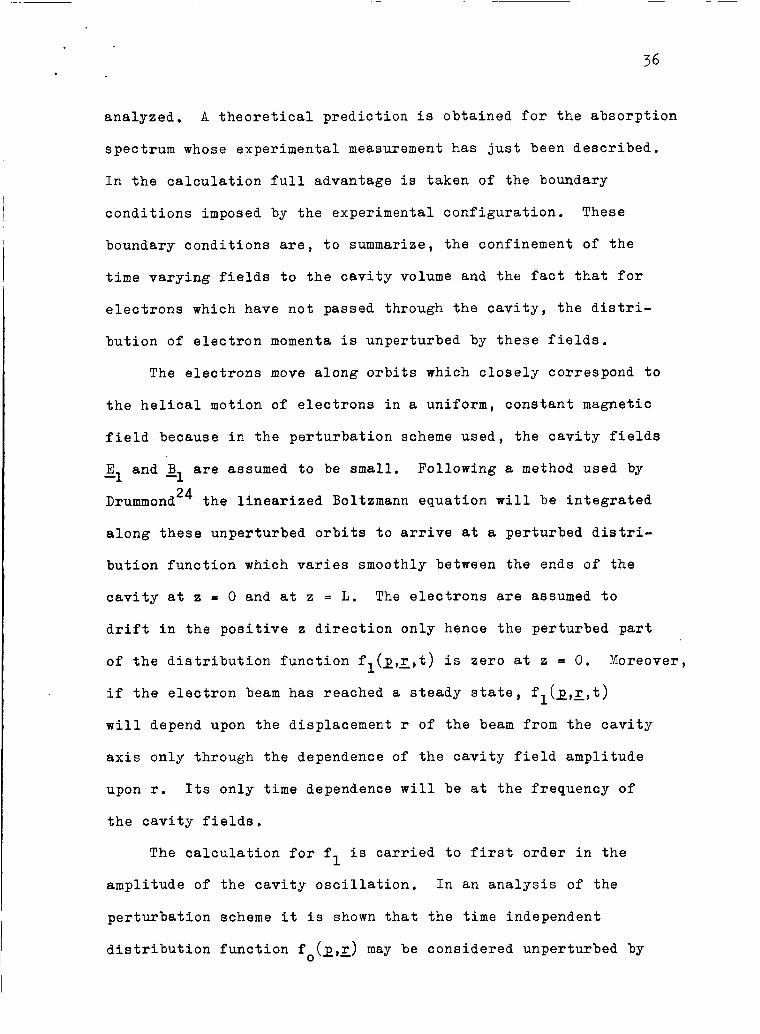
analyzed. A theoretical prediction is obtained for the absorption
spectrum whose experimental measurement has just been described.
In the calculation full advantage is taken of the boundary
conditions imposed by the experimental configuration. These
boundary conditions are, to summarize, the confinement of the
time varying fields to the cavity volume and the fact that for
electrons which have not passed through the cavity, the distri-
bution of electron momenta is unperturbed by these fields.
The electrons move along orbits which closely correspond to
the helical motion of electrons in a uniform, constant magnetic
field because in the perturbation scheme used, the cavity fields
E and B are assumed to be small, Following a method used by -1 -1 Dr~mrnond~~ the linearized Boltzmann equation will be integrated
along these unperturbed orbits to arrive at a perturbed distri-
bution function which varies smoothly between the ends of the
cavity at z = 0 and at z = L. The electrons are assumed to
drift in the positive z direction only hence the perturbed part
of the distribution function fl(l,x,t) is zero at z = 0.
if the electron beam has reached a steady state, fl(&,r,t)
will depend upon the displacement r of the beam from the cavity
axis only through the dependence of the cavity field amplitude
Moreover,
upon r. Its only time dependence will be at the frequency of
the cavity fields.
The calculation for f is carried to first order in the 1 amplitude of the cavity oscillation. In an analysis of the
perturbation scheme it is shown that the time independent
distribution function f (1,~) may be considered unperturbed by 0
37
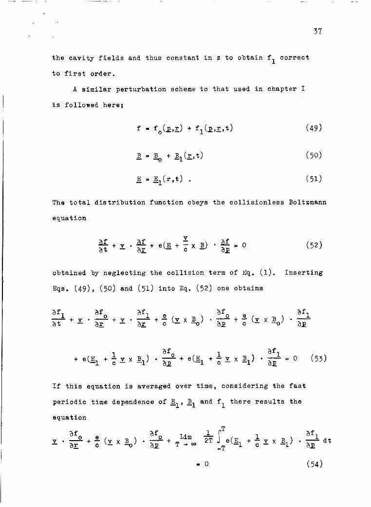
the cavity fields and thus constant in z to obtain fl correct
to first order.
A similar perturbation scheme to that used in chapter I
is followed here;
The total distribution function obeys the collisionless Boltzmann
equation
obtained by neglecting the collision term of Eq. (1).
Eqs. (49 ) , ( 5 0 ) and (51 ) into Eq. (52) one obtains
Inserting
If this equation is averaged over time, considering the fast
periodic time dependence of El, gl and fl there results the e quat ion
P O (54)
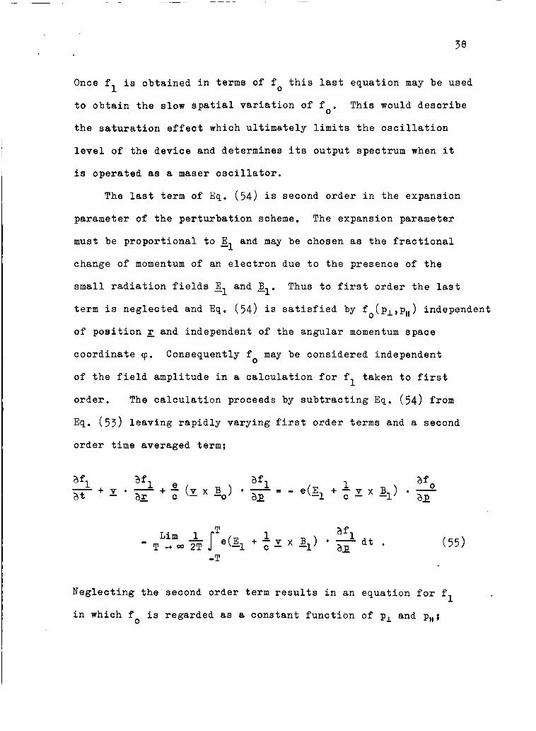
Once f
to obtain the slow spatial variation of fo.
the saturation effect which ultimately limits the oscillation
is obtained in terms of fo this last equation may be used 1 This would describe
level of the device and determines its output spectrum when it
is operated as a maser oscillator,
The last term of Eq. (54) is second order in the expansion
parameter of the perturbation scheme. The expansion parameter
must be proportional to gl and may be chosen as the fractional
change of momentum of an electron due to the presence of the
small radiation fields E and g1.
term is neglected and Eq. (54 ) is satisfied by fo(pl,pll) independent
of position; and independent of the angular momentum space
coordinate rp.
of the field amplitude in a calculation for fl taken to first
order. The calculation proceeds by subtracting Eq. (54) from
Eq. (53) leaving rapidly varying first order terms and a second
Thus to first order the last -1
Consequently fo may be considered independent
order time averaged term;
-T
Neglecting the second order term results in an equation for fl
in which fo is regarded as a constant function of pL and p,,;
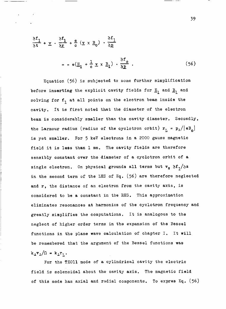
39
Equation (56) is subjected to some further simplification
before inserting the explicit cavity fields for El and gl and solving for fl at all points on the electron beam inside the
cavity. It is first noted that the diameter of the electron
beam is considerably smaller than the cavity diameter. Secondly,
the Larmour radius (radius of the cyclotron orbit) rL = p,/leBol
is yet smaller.
field it is less than 1 mm. The cavity fields are therefore
For 5 keV electrons in a 2000 gauss magnetic
sensibly constant over the diameter of a cyclotron orbit of a
single electron. On physical grounds all terms but vll af,/as
in the second term of the LHS of Eq. (56) are therefore neglected
and r, the distance of an electron from the cavity axis, is
considered to be a constant in the RHS. This approximation
eliminates resonances at harmonics of the cyclotron frequency and
greatly simplifies the computations. It is analogous to the
neglect of higher order terms in the expansion of the Bessel
functions in the plane wave calculation of chapter I. It will
be remembered that the argument of the Bessel functions was
k,v,/hl = klrL.
For the TEOll mode of a cylindrical cavity the electric
field is solenoidal about the cavity axis. The magnetic field
of this mode has axial and radial components. To expres Eq. (56)
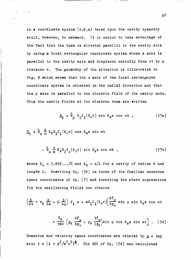
in a coordinate system (r,e,e) based upon the cavity symmetry
would, however, be awkward. It is easier to take advantage of
the fact that the beam is directed parallel to the cavity axis
by using a local rectangular coordinate system whose e axis is
parallel to the cavity axis and displaced radially from it by a
distance r. The geometry of the situation is illustrated in
Fig. 8 which shows that the x axis of the local rectangular
coordinate system is oriented in the radial direction and that
the y axis is parallel to the electric field of the cavity mode.
Thus the cavity fields at the electron beam are written
E = $ EIJ1(K,r) sin K,,z cos wt , -1 Y
B P 6 -1 x u 1.111 K E J (K, r ) cos Kllz sin ut
- 9 K E J (Klr) sin Kllz sin wt , z u 1 1 0
(574
where K, E 3.832.. ./R and K,, E n/L for a cavity of radius R and
length L. Rewriting Eq. (56) in terms of the familiar momentum
space coordinates of Eq. (7) and inserting the above expressions
for the oscillating fields one obtains
afO afo)sin cp cos Ktle sin ut] . (58) ap,, ymw (pi! a p ~ - + -
Momentum and velocity space coordinates are related by 2 = ymv
with y = (1 + p /m c ) . 2 2 2 9 The RHS of Eq. (58) was calculated

Fig. 8. Coordinate system f o r the in tegra t ion of t he l inear ized Boltzmann equation along the unperturbed o r b i t of an e lec t ron .
A A using the expression ex(afo/apl)cos 'p + e (afo/aPL)sin w
A + e
Y
af /ap for the momentum space gradient o f fo independent 2 0 t!
of cp.
The procedure introduced by Dr~mmond*~ is now used to solve
Eq. (58) for fl.
for solving a first order linear partial differential equation.
The characteristic curves for the operator on the LHS of E q . (58)
are just the unperturbed orbits in a single particle phase
space of an electron in the magnetic field s. of motion of these orbits are distributed according to fo(pL,pll).
The equations of motion
It is essentially the method of characteristics
i
The constants
are readily integrated to give
The constants of integration are chosen so that these primed

42
variables become the independent variables (pl.,~,pll,z,t) when
T = 0. It is easily verified that
Rewriting Eq. (58) in terms of the primed variables one obtains
- dfl = - eEIJ1(Klr) [ap afO sin(cp-Q.r) sin K 1 l ( ~ + ~ l l ~ ) cos W(t+T) d-r I
where
The limits of integration are due to the constants of motion of
Eqs. (60) which require that

43
The factor (p, afo/apL - pL afo/ap,,) in Eq. ( 6 3 ) originates
with the magnetic field of the cavity mode. It vanishes for
isotropic distribution functions fo( p) and this explains its
absence in the plane wave calculation of chapter I which was
carried through with the intent of showing that the growth
mechanism persists f o r isotropic distribution functions. Its
effect upon the absorption spectrum to be calculated now will
be discussed shortly.
The quantity which has been experimentally measured is the
average rate of absorption of cavity field energy by the electrons.
The instantaneous rate at which energy is absorbed by an electron
of velocity v at a point r in the cavity is e ~ l ( ~ ) - ~ . averaged rate of energy absorption by all electrons in the cavity
The time
may thus be formally written
-T
Applied to the configuration of fields considered here this
becomes
-T (67)
00 e L 00 2n
Jd2r n(r)J1(KLr)jds sin K,,z lpLdpL Jdcp sin cp Sapll p,E1cos ut fl. 0 0 0 0

44
Evaluating the integrals I1 and I2 of Eqs. (64a,b)
the result in Eq. (63) to obtain fl and inserting f 1 gives after performing the integrations over cp and z
inserting
in Eq. (67)
The following abbreviations are used in Eq. (68):
and
XX cos - 2 2 G(x) = [, - x21 ’
After an integration by parts Eq. (68) becomes
At this point it is expedient to establish the physical
significance of the various terms in Eq. (72). Beginning from
the left the quantity p defined in Eq. ( 6 9 ) expresses the
dependence of the absorption upon the electron density and upon
45
the amplitude of the cavity oscillation. The density varies only
in a plane perpendicular to the cavity axis and in Eq. (69) it
is weighted according to the radial variation of the cavity
field energy density. The integration extends over the cross
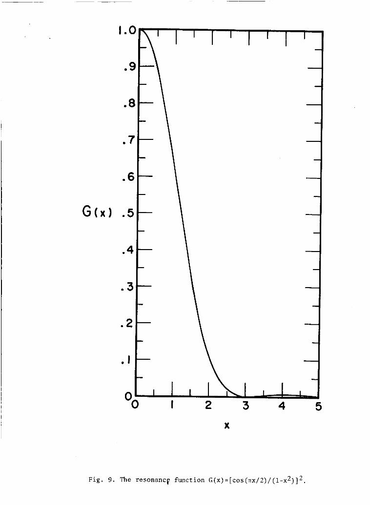
sectional area of the electron beam. The function G(x) defined
in Eq. ( 7 0 ) is sharply peaked about x = 0. It is the analog of
the Lorentzian resonance function of the plane wave analysis.
Its precise shape is shown in the plot of Fig. 9. The variable
x defined in Eq. (71) is the difference between the frequency
of the cavity oscillation and the cyclotron frequency of an
electron o f momentum p = (PI + p,,2)* measured in units of n
times the inverse of the time interval the electron spends in
2
the cavity. This establishes on an analytical basis the
equivalence of the roles of the transit time in the present -1 context with the relaxation time vc in the plane wave analysis.
Of the terms in the curly brackets of Eq. (72) only the
quantity 1 survives in the non-relativistic limit because the
factor multiplying the other terms (in the square brackets) is 2 of the order of vI /vIIc. Clearly this is subject to provision
that vI/vII does not tend to infinity.
would remain in the cavity f o r such long periods of time that
the whole linearization procedure would be in doubt since the
distribution of electron momenta would be more than slightly
perturbed by the cavity fields.
I
In that case the electrons
It is instructive to evaluate Eq. (72) for the simple
distribution
I .c
G o d
c . C
e €
. 7
*6
05
04
a 3
02
. I
0 0
Fig. 9. The resonance function G ( x ) = [ c o s ( 1 ~ x / 2 ) / ( 1 - x ~ ) ] * ,
46
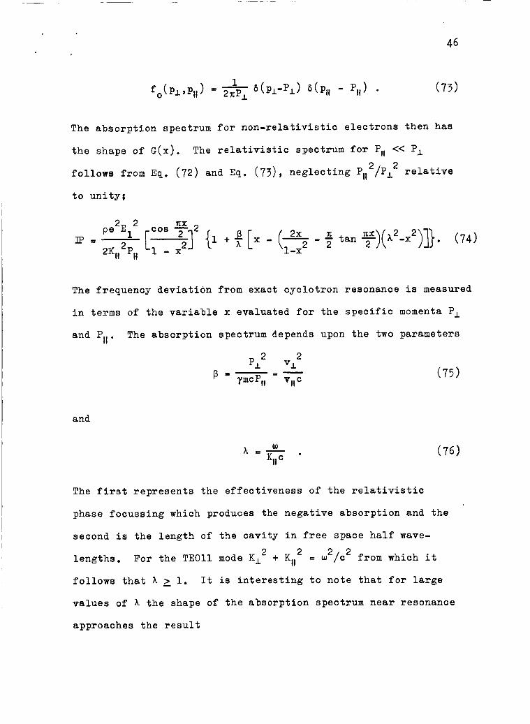
The absorption spectrum for non-relativistic electrons then has
the shape of G(x). The relativistic spectrum for P,, << P, 2 neglecting Pll /p: relative follows from Eq. (72) and Eq. (73)
to unityj
a 2 2 P13
1-x
The frequency deviation from exact cyclotron resonance is measured
in terms of the variable x evaluated for the specific momenta P,
and PII . The absorption spectrum depends upon the two parameters
2 2 p, VI
and
w A = - . Kll
( 7 5 )
The first represents the effectiveness of the relativistic
phase focussing which produces the negative absorption and the
second is the length of the cavity in free space half wave-
lengths.
follows that A 2 1. It is interesting to note that for large
2 2 + KII For the TEOll mode K, = u2/c2 from which it
values of A the shape of the absorption spectrum near resonance
approaches the result
47
obtained by neglecting the magnetic field of the cavity mode
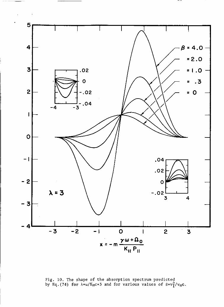
B -1 The general result Eq. (74), has been tabulated for a range
of values of the parameters A and p using the facilities of the
Yale Computation Center. Near exact cyclotron resonance (x2 < 1)
the spectra are substantially similar to the results of the plane
wave analysis plotted in Fig. 1,
the absorption oscillates between positive and negative values.
The peripheral oscillations between positive and negative absorption
of cavity field energy are, however, severely attenuated by the
factor G(x) which diminishes rapidly with increasing 1x1. The data
of Fig. 6 were obtained with a cavity which was approximately three
free space half wavelengths long. The computation of Eq. (74)
for A = 3 and for several values of p is plotted in Fig, 10.
For larger values of 1x1
Comparison of the theoretical curve with the measured
absorption spectrum shows qualitative agreement in so far as
the central portion of the spectrum is concerned. The peripheral
wiggles observed experimentally are, however, larger than those
theoretically predicted. It is possible that they may be caused
by inexact alignment of the cavity axis with the direction of
the magnetic field 3. The measurements of Fig. 6 were obtained with the electron beam near the cavity axis in which case slight
misalignment could cause the beam to cross the axis thus altering
the peripheral shape of the spectrum. Data obtained with a
‘ 5
4
3
2
I
0
- I
- 2
- 3
- 4
.02
- 0
-.02
- .04 -4 -3
x = 3
=2.0
= I .o = 03
= o
.04
.02
0
.02 3 4
-3 - 2 - I 0 1
7w+a0 x = - m Kll PI,
2 3
Fig . 10. The shape o f t h e absorption spectrum predicted by E q . (74) for A = w / K l l c = 3 and f o r var ious values o f B=vZ/vllc.

,
longer cavity ( h 4) with the beam displaced from the axis
exhibited no such wiggles. Indeed, they are theoretically so
small that they should not be clearly distinguishable on the
oscilloscope display.
The finer details of the absorption spectrum could be I obscured by any spread in the distribution of momenta p,, .
These experiments were in fact deficient in this respect since
such a spread could easily result from radial inhomogeneities
of the corkscrew magnetic field, Within the confines of the
experimental configuration no practical method for measuring
the actual distribution of parallel momenta was found. Lacking
such information no study of the second order effects of the
cavity fields upon the time independent distribution function
f was possible. The validity o f the linear analysis was inferred
from the constancy of the shape of the absorption spectrum as
the cavity field strength was reduced to a level too low to
significantly perturb the electron orbits.
0

49
111, Pulse Stimulated Cyclotron Radiation from Weakly Relativistic Electrons
1. The Response of MonoenerRetic Electrons to a Pulse of Cyclotron Resonance Radiation
An effect is now discussed which is related to the negative
cyclotron resonance absorption considered in the last chapter.
It will be shown that a system of relativistic electrons such as
the kind which will support growing waves near cyclotron resonance
responds to a short pulse of radiation at the cyclotron frequency
by emitting bursts of coherent radiation some time after the
pulse.
The essential features of the effect are described by
neglecting the motion of the electrons along the magnetic field,
considering them to execute cyclotron motion about fixed centers
of rotation in a region of uniform, constant magnetic field.
Before the radiation pulse the electrons are monoenergetic.
Immediately after it the energy of an individual electron depends
upon the phase of its cyclotron rotation with respect to the
incident radiation. The effect of the magnetic radiation field
is neglected as is the spatial variation of the incident radiation
field. Thus a small volume containing many electrons executing
cyclotron motion which for a short time experience a circularly
polarized radiation field is considered. The electric field lies
in a plane perpendicular to the constant magnetic field and rotates
in the same sense as the electrons at the cyclotron frequency of
the electrons prior to the pulse.

After the pulse the electrons' gyrofrequencies are distributed
according to the phase of the electron momentum with respect to
the instantaneous direction of electric field during the pulse.
Some electrons gain energy from the pulse thus decreasing their
gyrofrequencies and others lose energy with consequent decrease
in mass and increase of gyrofrequency. The subsequent motion
under the influence of the uniform, constant magnetic field
alone produces a succession of radiation bursts. It will be
shown that the amplitude envelope of these bursts is simply
expressed in terms of Bessel functions and is approximately
[J (t/T)]
by the exciting pulse.
2 for slight perturbation of the initial electron momenta 1
An important approximation made in the calculation of the
radiation emanating from a small volume containing the electrons
is that the radiation emitted after the pulse does not affect
the electron orbits. Thus the theory is limited to low electron
densities where a comparison of the exciting pulse amplitude
and maximum radiation amplitude justifies the approximation.
The theory predicts that for weak perturbations of the electron
orbits, about one third of the total possible coherent emission
power into free space will be radiated during the first burst.
The effect bears an interesting relation to negative cyclotron
resonance absorption of a steady excitation by virtue of the phase
focussing which causes it. The same phase focussing in momentum
space that produces the net rotating dipole moment density in
response to a pulse also produces currents when the plasma is
steadily excited which can feed energy to the wave. There is,
51
however, one essential difference between the treatment of a
steadily excited plasma in the preceding chapters and the kinetic
theory of the electron plasma (after experiencing the pulse)
to follow. The former involved a perturbation theoretic solution
of the Boltzmann equation whereas the latter will involve an exact
solution which is a trivial consequence of the Liouville theorem.
In the theory the pulse is considered to produce an initial
distribution function, the subsequent behavior of which is
determined by the incompressible flow of electrons in a single
particle phase space demanded by the Liouville theorem.
An experiment which has provided qualitatively corroborating
results will be described.
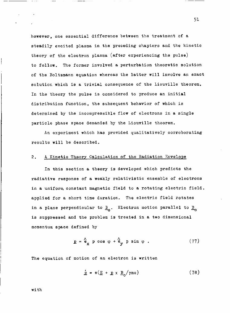
2. A Kinetic Theory Calculation of the Radiation Envelope
In this section a theory is developed which predicts the
radiative response of a weakly relativistic ensemble of electrons
in a uniforrq constant magnetic field to a rotating electric field,
applied for a short time duration. The electric field rotates
in a plane perpendicular to G . is suppressed and the problem is treated in a two dimensional
momentum space defined by
Electron motion parallel to Bo
x=$,pcoscp+e A psincp. Y
The equation of motion of an electron is written
( 7 7 )
with

2 2 2 & y = ( l + p / m c ) .
The electric field is given as
A A E = E(ex sin ut t e cos ut) Y -
52
(79 )
and is understood not to vanish only for a short time interval
At.
If Eqs. ( 7 7 ) , ( 7 9 ) and (80) are used in the equation of
motion Eq. (78) the result
d A d G - (p cos c p ) + e - (p sin cp> x dt Y dt
A = a x ( R p sin cp + eE sin ut) + e (-Rp cos cp + eE cos ut) (81) Y
is obtained which is equivalent to
d -iwt - (peiY) = -inpeitP + ieEe dt
The usual symbol n for the relativistic cyclotron frequency
eBo/ymc is used. The transformation o f variables
cp' = ql + Rt
P' = P
is now introduced. It represents a physical transformation t o
a momentum space coordinate system (p' , y t ) rotating with respect
t o the original system (p,cp) at an angular frequency equal to
gyration frequency of the electron's motion in the original

53
system. It simplifies the solution of Eq. (82) considerably.
Rewriting Eq. ( 8 2 ) in terms of the primed variables gives
-i (w-n) t d (p'eiv') = ieEe dt
as the equation of motion of an electron in the rotating momentum
space coordinate system.
The frequency w of the exciting electric field is assumed
to be equal to the cyclotron frequency fl of the electrons before
the pulse.
short time intervals At. The implication is that the magnitude
and phase of the momentum p are changed impulsively and that
during At the relative phase slip between the momentum 2 and the
electric field E (due to the change in the cyclotron frequency
with changing p) is small.
frequency of an electron from its value R at t - 0 is An, the condition for negligible phase slip during the pulse may be
expressed as ARAt << 1. For slight perturbations of the momenta
of weakly relativistic electrons (i.e. Ap << p << mc) the
condition is explicitly written
In that case the RHS of Eq. ( 8 4 ) is constant for very
If the maximum change of the cyclotron
2 2 noAt << - m c
PAP
The pulse duration At is assumed to be small enough to satisfy
this inequality and Eq. (84) is integrated trivially from t = 0
to t = At to give

I
After the pulse (t > At) the RHS of Eq. (84) vanishes and
p I eitP is constant in time. Thus for t > At
54
iTo I = pole + ieEAt
The next step transforms this result for the rotating momentum
space coordinates into the result for the non-rotating momentum
coordinates by applying Eqs. (83a,b) once more to obtain
-i - t Y p(t)eiq(t) = (poe itPo t ieEAt) e
where
The analysis of the dynamical behavior of a single electron
after the pulse is concluded by writing the magnitude of the
momentum in terms of its initial momentum coordinates. Multiplying
Eq. ( 8 8 ) by its complex conjugative directly gives
(P(t>I2 = Po + 2eEAtpo sin yo + (eEAt)2 . ( 8 9 )
An expression for the power radiated by a number N of such
electrons confined to a volume larger in dimension than the
orbital radius and smaller than the wavelength of the radiation
emitted is obtained from Larmor's formula25 for the total power
radiated by an accelerated electron. For an electron in
instantaneous circular motion at an angular velocity R Larmor's

formula gives
In rder t a1 ul
IP=
te the p
(93)
wer radiated by N electrons contained
in a small volume which have been perturbed by a pulse in the
manner described above, p in Eq. ( 9 0 ) is replaced by the
statistically summed momentum of the N electrons:
0 0
The kinetic theory of the problem enters in the integration over
momenta distributed according to f ( p ,cp, t) after the pulse.
Since there is no transport of electrons in position space,
the incompressible flow of the electron gas in phase space
demanded by the Liouville theorem 2 6 y 2 7 requires that
f(PW ,&) ,t> P dPdY = f(Po,'p0A PodPodtpo (92)
if (p(t),cp(t)) are related to (po,cpo) by Eq. ( 8 8 ) , the solution
of the equation of motion of a single electron. Using this
result in Eq. (91) and substituting the RHS of Eq. (88) for
peiy together with Eq, (90) gives for the power radiated as a
function of time n
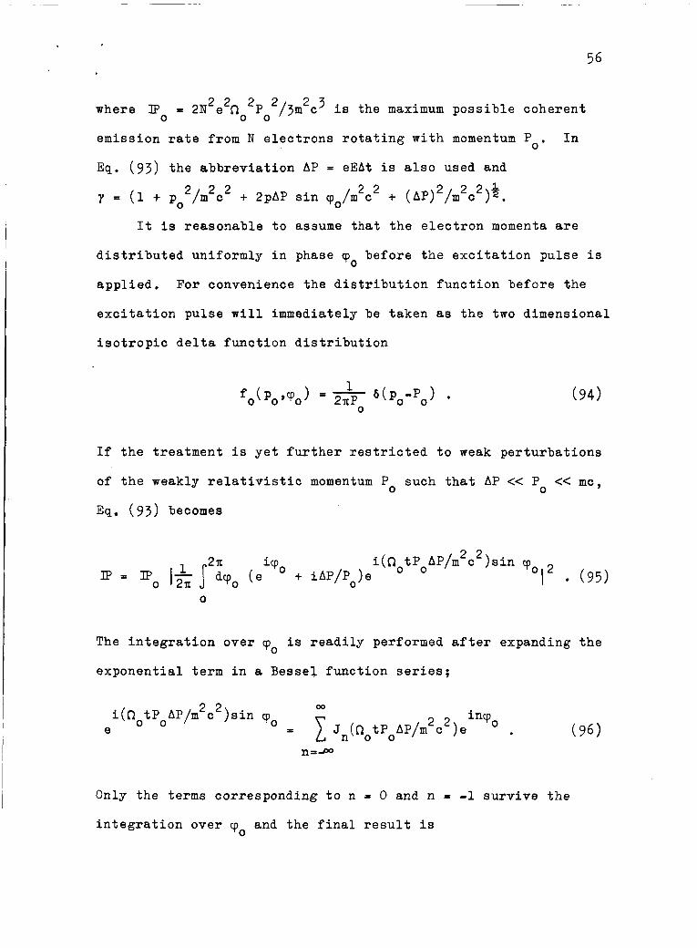
56
where a ? = 0
2 2 2 2 2N e no Po /3m2c3 is the maximum possible coherent
emission rate from N electrons rotating with momentum Po.
Eq. (93) the abbreviation AP = eEAt is also used and
In
2 2 2 2 2 & y = (1 + po2/m2c2 + 2pAP sin q0/m c + (AP) /m c ) ,
It is reasonable to assume that the electron momenta are
distributed uniformly in phase 'po before the excitation pulse is
applied. For convenience the distribution function before the
excitation pulse will immediately be taken as the two dimensional
isotropic delta function distribution
If the treatment is yet further restricted to weak perturbations
of the weakly relativistic momentum Po such that AP << Po << mc,
Eq. (93) becomes
i(QotPoAP/m 2 2 c )sin cpo icpo
Ip = Po I & ficp0 (e + iAP/Po)e I (95) 0
The integration over cp is readily performed after expanding the 0
exponential term in a Bessel function series:
2 2 00
i(RotPoAP/m c )sin cpo 2 2 inVo e = 1 Jn(QotPoAP/m c )e
Only the terms corresponding t o n = 0 and n = -1 survive the
integration over cpo and the final result is

57
where 2 2 = m c /PoAP .
OOT
Equation ( 9 7 ) representing the time dependence of the amplitude
of pulse excited radiation by N electrons localized in a small
volume is a physically useful result only if the rest of space
is empty and thus causes no dispersion or absorption of the
emitted radiation. In fact Larmor's formula applies only f o r a
single particle in free space and the assumption in the present
context is that the ensemble average charge acceleration of
closely situated electrons causes the same radiation as a single
particle of charge Ne possessing the statistically averaged
momentum of the N electrons. If the electrons were spread out
over a region,comparable in size with the wavelength of cyclotron
emission the present model would be inadequate. It would not
account for the phase difference of the excitation pulse at various
points in the electron gas nor would it account for the interference
of the cyclotron radiation emitted by spatially separated groups
of electrons. The model offered here is sufficient to illustrate
the basic radiative behavior of pulse stimulated relativistic
electrons in a uniform magnetic field. It is also a sufficiently
comprehensive theoretical model for the experiment to be described
as should become evident in the course of its discussion in the
section to follow.

58
The current associated with the first term on the RHS of
Eq. ( 9 7 ) vanishes near t = 0 and develops in time as a consequence
of the relativistic phase focussing. On the other hand the
second term involving Jo is maximum at t P 0 . It accounts for
the dipole moment induced immediately by the excitation pulse.
For AP << P this term is small and the radiation intensity
envelope is closely approximated by the first term alone, 0
IP M Po Jl2(t/7) .
Experiments have been performed in an effort to observe the
time dependence indicated in Eq. ( 9 8 ) .
3 . The Experimental Method
The apparatus used to verify experimentally the above
theoretical considerations is schematically illustrated in Fig. 11.
The vacuum system, electron gun, corkscrew magnetic field and
axial magnetic field configuration are substantially the same
as used in the experiment described earlier although the region
immersed in the uniform (h.05 percent) magnetic field & is longer. The electrons drift consecutively through two microwave cavities
in this region. They are separated by a distance L = 35 cm and
the electrons interact with their fields over a length 1 = 3.5 cm.
The corkscrew magnetic field and axial magnetic field in
the corkscrew region are carefully adjusted to produce a slowly
drifting weakly relativistic electron beam in the cyclotron
resonance region. The delta function distribution (given by Eq.
( 7 3 ) ) which specifies one particular value of transverse momentum
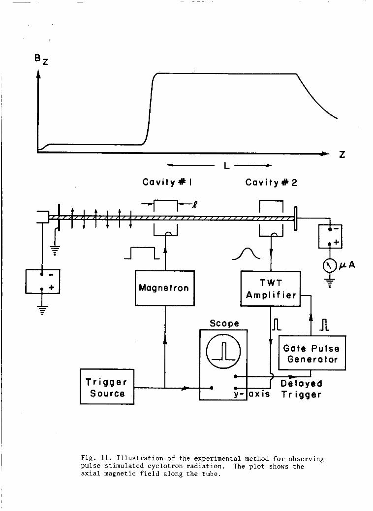
- L-
C a v i t y X I C a v i t y R 2
- - e
A m p l i f i e r Magnetron 7 Scope
0-c Gate P u l s e Ge n e r a tor
d D e l a y e d
y - l a x i s T r i g g e r
Fig. 11. Illustration of the experimental method for observing pulse stimulated cyclotron radiation. axial magnetic field along the tube.
The plot shows the
59
P, and one value of parallel momentum PI, together with the
conditio:: PI, << P, << mc are considered to describe the beam in
that region. As the electrons drift through the first cavity
which is driven by an external microwave signal generator, they
experimence the excitation pulse for a time interval ymA/P".
This time interval is to be associated with At of the preceding
section. After a delay time ymL/P,, (equal to the time of flight
of an electron between the two cavities) the electrons enter the
second cavity which functions as a sensitive receiving antenna
for the radiation emitted by the electrons within it. This delay
given setting of the electron beam characteristics the quantities
t and At are fixed. The natural experimental parameter to vary
is the amplitude of the excitation field in the first cavity
thereby varying AP. The amplitude of the oscillation stimulated
in the second cavity by the electrons should therefore reflect
the AP dependence of the radiation power specified by Eq. ( 9 7 ) .
The cavities were designed t o resonate in the TMOlO mode at
6525 Mc/sec and were oriented so that their axes of cylindrical
symmetry were perpendicular to s. mode was perpendicular to & and the electron beam traversed the cavity diametrically. The cavities were of identical construction,
although, for precise alignment, they were made tunable by inserting
a tuning slug through one flat end of each. The slug, l / 4 inch
in diameter, could penetrate the cavity to a depth of about 3 / 8
inch along its axis providing a tuning range of 100 Mc/sec.
vacuum integrity of the mechanism was maintained with a stainless
Thus the electric field of the
The
steel flexible bellows.
60
Coupling to the cavities was accomplished through ceramic
vacuum windows mounted exactly as for the steady state absorption
experiment described earlier. The cavities were joined to
sections of 1/2 inch I . D . stainless steel pipe which connected
to the magnetic corkscrew section via vacuum flanges. The same
water cooled collector as described earlier was used. The entire
assembly was fabricated of type 304 non-magnetic stainless steel
and all joints were brazed with copper in vacuum or welded in
an inert gas atmosphere. After extended bakeout of the entire
vacuum chamber operating pressures of 2 x lo-’ mm Hg were
achieved.
The microwave electronics consisted basically of a signal
generator whose output power could be continuously varied by an
attenuator, and a sensitive microwave receiver. The attenuated
output of the microwave signal generator was fed to the first
cavity and the receiver which consisted of a TWT amplifier and
a crystal detector was coupled to the second cavity. The minimum
detectable signal for this simple arrangement was 10 watts. -10
Referring to Fig. 11 it is observed that the signal source
used for the excitation field in cavity No. 1 was a pulsed
magnetron and that the receiver was gated. This was done for
technical reasons to be described forthwith. It is to be emphasized
that the excitation pulse duration is determined only by the time
of flight of an electron across cavity No. 1 and that the delay
between the excitation pulse and the observation of the resulting
cyclotron emission is due only to the time of flight of an
electron between the cavities. The intermittently operated
61
magnetron was used because it was the only available source
which provided the required power level.
The receiver was gated in synchronism with the intermittent
operation of the magnetron by applying a short rectangular pulse
to the grid of the traveling wave tube. The oscilloscope thus
measured the rectified output of the TWT amplifier at the same
time during each successive magnetron output pulse. The operation
of the apparatus therefore simulated steady state operation.
The only difference was that instead of measuring the continuous
output of microwave energy from cavity No. 2, it was measured
over a short period of time.
The magnetron pulse was approximately 400 nanoseconds long.
Since the fields in the oavities, for which the Q was about 1600,
do not build up too quickly on this time scale the gating of the
receiver was crucial. The gate width could be varied between
10 and 100 nanoseconds. The odd shape of the magnetron pulse
amplitude envelope also suggested that care be taken to observe
the radiation level at the same time in each repetition of the
experiment. The recourse to gating the receiver dealt effectively
with these problems and there were no ambiguities introduced
by using an intermittently operated signal source.
added that the repetition rato of the magnetron which operated
at 6525 Mc/sec was 700 pulses/sec.
It should be
The experiments were performed with low current electron
beams (- 10 microamperes) so that the TMOlO mode oscillation
stimulated in the second cavity by the electronswasnegligible
in amplitude compared with the externally driven oscillation in
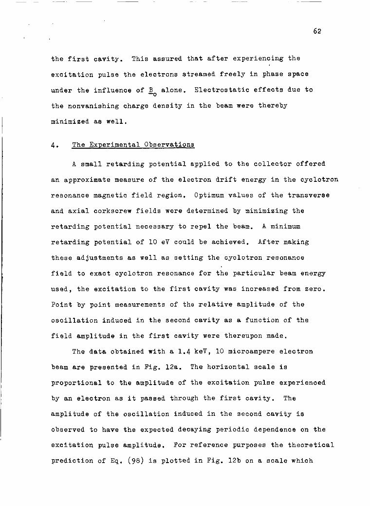
62
the first cavity. This assured that after experiencing the
excitation pulse the electrons streamed freely in phase space
under the influence of B alone. Electrostatic effects due to
the nonvanishing charge density in the beam were thereby
minimized as well,
-0
4. The Experimental Observations
A small retarding potential applied to the collector offered
an approximate measure of the electron drift energy in the cyclotron
resonance magnetic field region. Optimum values of the transverse
and axial corkscrew fields were determined by minimizing the
retarding potential necessary to repel the beam. A minimum
retarding potential of 10 eV could be achieved. After making
these adjustments as well as setting the cyclotron resonance
field to exact cyclotron resonance for the particular beam energy
used, the excitation to the first cavity was increased from zero.
Point by point measurements of the relative amplitude of the
oscillation induced in the second cavity as a function of the
field amplitude in the first cavity were thereupon made,
The data obtained with a 1.4 keV, 10 microampere electron
beam are presented in Fig. 12a. The horizontal scale is
proportional to the amplitude of the excitation pulse experienced
by an electron as it passed through the first cavity. The
amplitude of the oscillation induced in the second cavity is
observed to have the expected decaying periodic dependence on the
excitation pulse amplitude. For reference purposes the theoretical
prediction of Eq. ( 9 8 ) is plotted in Fig. 12b on a scale which
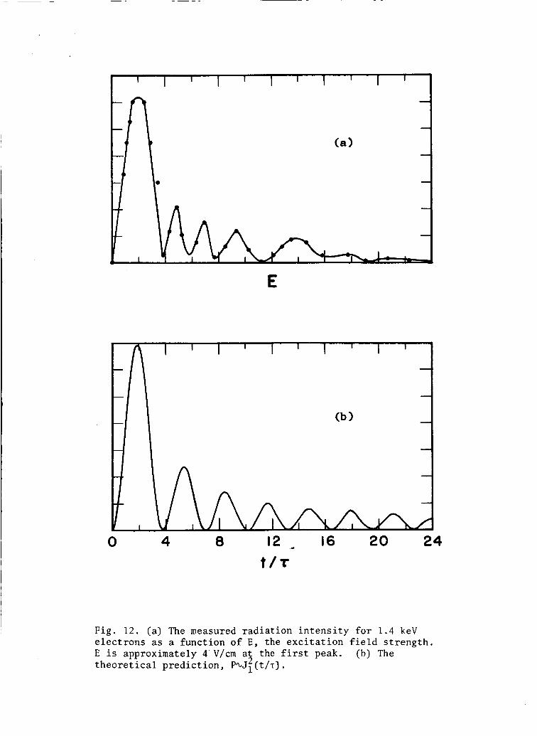
E
0 4 8 12 - 16 20 24
t /r
Fig. 12. (a) The measured radiation intensity for 1.4 keV electrons as a function of E, the excitation field strength. E is approximately 4'V/cm at the first peak. (b) The theoretical prediction, PaJ;(t/.r).
allows the first experimental peak and the first theoretical
peak to coincide.
An approximate value for the excitation field intensity at
the first peak was obtained from measurements of the Q, coupling
factor and power incident upon the first cavity. For the data
of Fig. 128 this electric field was 16 V/cm at the center of the
cavity. In view of the fact that the impulse AP = eEAt received
by an electron is effectively determined by the average field
across the diameter of the cavity this figure should be reduced
accordingly. Multiplication by 1/2 gives a reasonable estimate
for the average field. A final correction factor, exactly equal
to 1/2, enters as a consequence of the linear polarization of the
electric field of the cavity mode, The electronic motion is
coupled strongly only to that circularly polarized component
which rotates in the same sense as the electrons. The effective
excitation pulse amplitude E is therefore 4 V/cm.
At = ymh/Pl,, t = ymL/P,, and t/T = 1.84.. . the energy of electron drift along% is calculated to be 20 eV.
With
No completely satisfactory explanation for the discrepancy
between the experimentally measured and theoretically predicted
spacing between the peaks is at hand. However, one could not
expect the simple result Eq. ( 9 8 ) plotted in Fig. 12b to apply
exactly for several reasons. The foremost objection is that the
condition for the impulsive approximation used in the electron
dynamics is not too strictly adhered to. This condition, expressed
in Eq. (85), is equivalent to At << T. The ratio of the cavity
diameter to the inter-cavity distance specifies that

64
At/t = A/L = 1/10.
the second cavity t/T = 1.84, 5.33 , 8 . 5 3 , . . . etc. and the condition is clearly violated for peaks after the third. The
fact that the peaks tend to disappear for At - T is consistent
For successive radiation peaks to occur at
with this picture.
It is concluded that the effect has been observed, albeit,
only to a qualitative degree of accuracy.

65
IV. Cyclotron Resonance Absorption by Low Energy Electrons Elastically Scattered in a Neutral Gas Background
1. General Remarks
With a shift in emphasis from relativistic phenomena to low
energy collision phenomena, negative cyclotron resonance absorption
due to electron-neutral atom elastic scattering is now discussed.
Ordinarily collisions are regarded as a dissipative mechanism
which causes damping of any mode of oscillation in a plasma by
destroying the phase order of the motion of the plasma particles.
In reality collisions can cause the growth of an oscillation in
a non-Maxwellian plasma.2
cyclotron resonance interaction in a tenuous, monoenergetic,
infinite plasma of electrons in chapter I.
This was shown for the case of the
The analysis of chapter I assumed that collisions are
adequately described by the simple relaxation appr~ximation’~ given
in Eq. (8).
to delve into the theoretical justification for this model as it
applies to collisions between electrons and neutral atoms although
a few words in support of its use will be said. Its foremost
virtue is that it makes the analysis involved in the solution of
the linearized Boltemann equation tractable. Secondly, it has the
desired effect of disordering the phase ordered motion associated
with first order currents in the perturbation theory used. The
ability of the neutral atom scatterers to randomize the first
order currents associated with electrons of different energy at
different rates is inserted into the model by allowing the collision
It would be beyond the intended scope of this work
66
frequency vC to be functionally dependent upon the magnitude of
the momentum of the scattered electron. The electrons are
assumed to be scattered elastically.
The relaxation approximation is objectionable on the grounds
that it usually does not conserve particle number, momentum and
energy which are conserved in elastic collisions. A physically
consistent treatment of binary collisions must begin with the
Boltzmann collision integral. A connection between the Boltzmann
collision integral and the relaxation approximation has been
worked out by Desloge and Matthysse. 28
appropriate relaxation frequency v is the collision frequency
for momentum transfer.
They point out that the
C
The attitude to be chosen here will be to accept the results
of chapter I as suggestive of the existence of negative absorption
by slow electrons due to collisions (physical inconsistencies
notwithstanding) and to offer a comparison with experimental
data. The same technique of microwave spectroscopy as was used
in the study of cyclotron resonance absorption by relativistic
electrons was used in the presently discussed study of the absorption
by slow electrons in a low pressure neutral gas background. The
generation of the necessary distribution of electron momenta was
not as involved as it was in that work since nothing as complicated
as the corkscrew magnetic field device was necessary.
A beam of low energy electrons formed in a region of low
magnetic drifted along converging field lines into the uniform cyclo-
tron resonancemagnetic field region. The magnetic mirror effect
and collisions with neutral gas atoms along the drift path

provided a distribution of momenta between the direction per-
pendicu1.ar to the magnetic field and the direction parallel to
it. Thus with a significant part of the energy of the mono-
energetic distribution of momenta associated with rotational
motion, low field intensity in the microwave cavity and with
sensitive detection the validity of the perturbation theory was
assured.
The obvious choice of background gases were the rare gases
Argon, Krypton and Xenon whose elastic collision cross sections
possess a Ramsauer minimum15 near 1 eV.
these gases rise steeply for a few eV above the Ramsauer
minimum. A multitude of papers have appeared in the last few
years describing the radio frequency and microwave emission
and absorption characteristics of discharge tube plasmas of these
gases. For the particular case of the cyclotron resonance
interaction, among the most notable are the calculations offered
by Tanaka and Mitani2g which extend the earlier work of Bekefi,
Hirshfield and Brown2 and of Twi8s.l
Terumichi et a,.” reported the observation of an anomalously
large transmission of radiation at cyclotron resonance through
a Xenon discharge plasma and attributed it to the collisional
growth mechanism.
the amplification of a signal incident upon a microwave cavity
containing a Xenon discharge in a cyclotron resonance magnetic
field. The experiments reported in these papers are singularly
deficient in their ability to support the theoretical work since
the data is difficult to interpret in anything but a qualitative
The cross sections of
Shortly thereafter
In a later paper’? the same authors reported
68
sense. One exception to this trend in the experimental work are
the measurements of the radiation temperature of various rare
gas discharges by Fields, Bekefi and Brown. 31
In all the experimental work to date the basic shape of the
absorption spectrum which exhibits the negative dip illustrated
in Fig. 2 could not be resolved because a broad distribution of
electron energies was involved. The experiments with monoenergetic
distributions (to be described below) were performed in an effort
to observe the dip and show that it occurs only for energies at
which the cross section for collisions with neutral gas atoms
increases sharply with electron energy. Only the phenomena
associated with increasing collision frequencies was studied,
The predictions of Fig. 3 for decreasing vc do not apply to the
experiments that were performed.
2. Measurements of the Absorption Spectrum
The apparatus was similar, with a few modifications, to the
equipment illustrated in Fig. 4. The configuration of magnetic
fields was exactly the same as for the energetic electron
ab%tion experiment with the exception of the corkscrew winding
which was eliminated. The microwave cavity, which was smaller,
operated in the TMOlO mode at 5782 lk/sec and was oriented with
its axis of cylindrical symmetry (and thus its electric field)
perpendicular to %. diametrically.
The electron beam traversed the cavity
Immediately before entering the cavity the electron beam
passed through a grid structure consisting of three parallel
69
grids in planes perpendicular to the axis of the tube. The grids
were approximately 5/16 inch apart and the outer two were
electrically grounded to the tube wall. The inner grid was
supported by a tungsten wire which passed through the side wall
of the tube via a l / 4 inch diameter glass to stainless steel
housekeeper seal. A negative square wave potential applied
to this grid was used to modulate the electron beam in the cavity.
A variable retarding potential applied to a similar grid structure
just after the cavity was used to measure the distribution of
energy associated with motion along B -0.
The grid was formed of a commercially available knitted
tungsten wire mesh.
tungsten wire provided a grid which would transmit 97 percent
of the incident electron current. The mesh was sandwiched
between circular stainless steel frames which were spot welded
together. The frames were then mounted within the tube structure.
Assembly of the cavity and grid structures was facilitated by
dividing this part of the tube into separate sections machined
from stainless steel stock. The completed sections were joined
to form a vacuum tight chamber by welding in an inert gas
atmosphere. Type 304 non-magnetic stainless steel was used
throughout.
The 1/16 inch spacing between the .001 inch
The schematic diagram of the apparatus in Fig. 13 shows the
microwave spectrometer and detection system which consisted of a
TWT amplifier, crystal detector and a lock-in amplifier for
synchronous detection of the absorption signal. The reference
signal for the synchronous detector was derived from the 10 Kc/sec
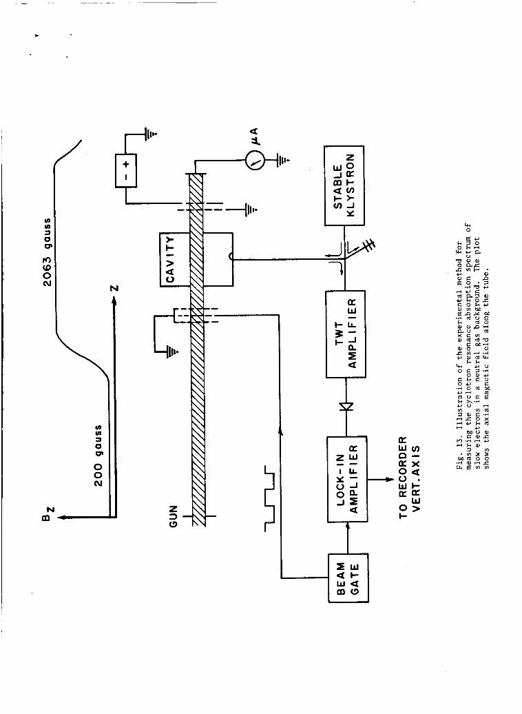
u) u) 3 0 Q
rr) CD 0 cu
u) u) 1 0 e 0 0 cu
N m-
N
a
VI 0
negative square wave voltage applied to the beam gating grid.
The output of the lock-in amplifier was plotted on the vertical
scale of an X-Y recorder whose horizontal trace was swept slowly
in synchronism with the cyclotron resonance magnetic field
intensity B 0'
The absorption was measured as a function of B for various 0
electron gun potentials in vacuum and in the background gases
Argon, Krypton and Helium. It was found that the best method
for maintaining a constant low background gas pressure (usually
less than lom3 mm Hg) was to feed gas to the system via a small
aperture leak valve while continuously pumping the system. The
data thus obtained is exhibited in Figs. 14 through 17 for Argon, in
Figs, 18 through21for Krypton and in Figs. 22 and 23 for Helium.
The numbers to the upper left of each trace denote the gas
pressure measured directly on a Bayard Alpert type ionization
gauge which was calibrated for nitrogen. To correct for the
difference of the ionization probabilities of the gases used
the indicated readings should be multiplied by the following
factors :
Argon: multiply by 0.85
Krypton: multiply by 0.53
Helium: multiply by 6.22
These correction factors are quoted from the manufacturer's
recommendations.
The narrow absorption line on the right hand side of the
spectra is interpreted as the electron cyclotron resonance
absorption. Its observed linewidth for electrons in vacuum
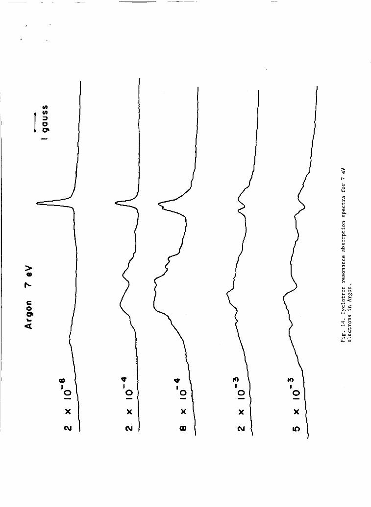


> 0 Q)
- C 0 Q, L a
4 1 0
X
cu
c
e,
I?

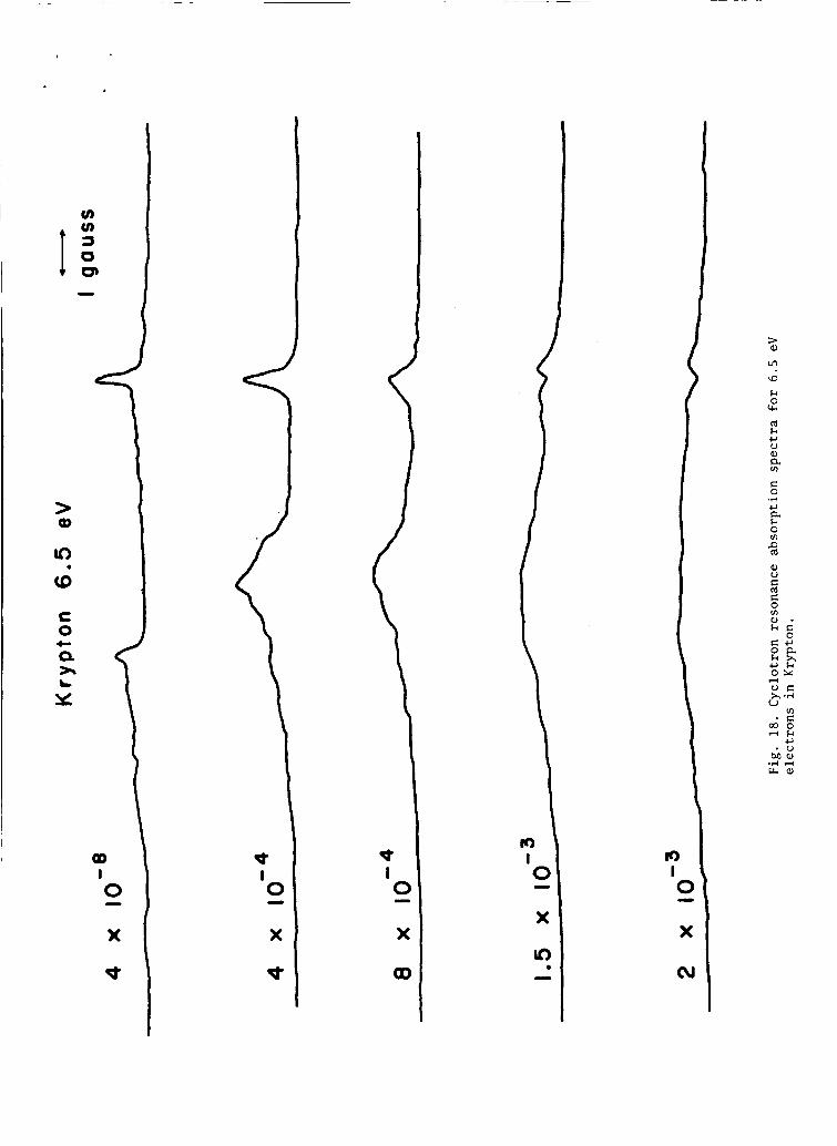
I
k 0 +I

u)

E 0
.r(
c, a k 0 vr e cd Q, V E a c 0 m Q , - k E 0
G I ,
Crk O Y
x 4 U
m - c 0 0

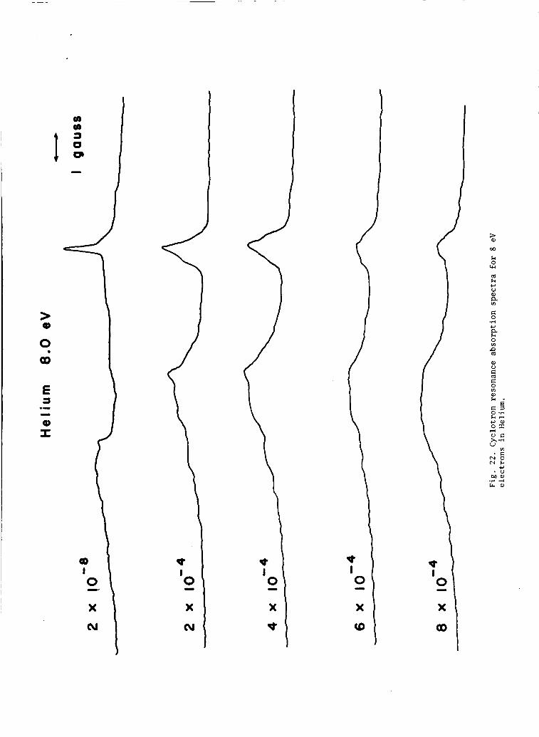
% 00
k 0 ru td k c, V a, a u)
G 0 .?I c, a k 0 u)
% a, V C td C 0 In a,
2 0 .r i
k 3 c ,Q) o r U F x .?I u
v1 * F N O N k
c, . U
Ma, .?I 3 ua,
3

k 0 vc d k c, V 0,
@ E: 0 .?I c, a h 0 VI P d

was in better agreement with estimates of the transit time
broadening from drift energy neasurements obtained with the
second grid structure. In general, the average drift energy
was between one fourth and one half of the total beam energy
and the spread was moderately large. Fewer than 10 percent
of the electrons in a given monoenergetic beam had less than 1 eV
of drift energy or more than all but 1 eV of drift energy for the
total beam energies represented in the data.
Referring to the data for Argon, the dip in the cyclotron
resonance absorption line is observed to be progressively stronger
in the spectra for 7 eV, 9 eV and 10 eV electrons. The Argon
collision cross section for momentum transfer increases monotonically
from the Ramsauer minimum until it levels off at about 12 eV.
Only a slight suggestion of the dip appears in the data for 12 eV
electrons in Argon.
The relative depth of the dip increased with pressure as it
should have up to the point that collisions were the dominant
broadening mechanism. At sufficiently high pressures the time
that an electron spent in the cavity did not determine the width
of the cyclotron resonance line. As the pressure was increased,
the beam current was concurrently reduced from its approximately
1 microampere value in vacuum by scattering of the electrons along
their long drift path from the cathode. An upper practical limit
to the background gas pressure was thus reached at about l oo3 mm Hg depending upon the gas used.
The behavior of the cyclotron resonance absorption lineshape
for Krypton w a s entirely similar except for the fact that the dip
72
disappeared completely at 10 eV. The cross section for Krypton
levels off at about that energy. Measurements made with a
background of Helium at electron gun potentials of 8 volts and
9.5 volts exhibit no dip at all. In this energy range the cross
section for Helium is inversely proportional to the electron
velocity and the collision frequency is, therefore, constant.
The momentum transfer cross section information was obtained
from the work of Frost and Phelps’2 who have combined and compared
the measurements of many workers.
At this point the persistent occurence of the broad
absorption at lower values of Bo than the absorption line identified
as due to the cyclotron resonance interaction should be discussed.
However, no explanation of its origin is available and it would
be premature if not impossible to argue in favor of any speculative
guesses. Within the context of this presentation its existence
is noted and the contention that it does not alter the identifi-
cation of the cyclotron resonance absorption is made.
3 . Calculation of the.Csclotron Resonance Absorption Spectrum
From the foregoing remarks it appears that two parameters
determine the shape of the cyclotron resonance absorption measured
in these experiments. The first would be analogous to the single
parameter a = Pvcl(P)/v (P) involved in the infinite plane wave
analysis of chapter I. The second would express the number of
collisions that an electron might be expected to suffer during
the time it spent in the cavity.
from an analysis like the one offered in chapter 11, section 5
C
Two such parameters evolve

.
for the case of relativistic electrons in vacuum.
For the present problem the linearized Boltzmann equation
with the relaxational collision term is integrated along the
unperturbed orbit of an electron as it traversed the cavity.
The first order distribution function fl(i,r,t) is thus obtained
and the field energy absorbed by the electron beam is calculated
as indicated in Eq. (66).
unperturbed by the presence of the electron beam and as in the
calculation of chapter 11, are assumed to be those of the empty
resonator.
The fields are considered to be
Since the electrons are non-relativistic the magnetic field
of the cavity mode is neglected. The electric field is assumed
to have a simpler spatial dependence than the actual zeroth order
Bessel function variation of the electric field of the TMOlO
mode. It is assumed to oscillate with constant amplitude at all
points on the electron beam subtended by the cavity, to vanish
at points outside the length L subtended by the cavity and to lie
along the e direction. Y
h The magnetic field Bo is parallel to
and the unperturbed orbits are once again given by Eqs. (60). Z
~
73
The
afl at +
-
linearized Boltzmann equation thus becomes
The arguments that precede Eq. ( 5 8 ) also apply to the development
o f Eq. ( 9 9 ) . Noting the parametrization of the unperturbed orbits
in Eqs. (60) and the result in Eq. (61), the solution to Eq. ( 9 9 )
is seen to be

74
Def in ing n as t h e e l e c t r o n d e n s i t y of t h e beam whose c r o s s
s e c t i o n a l a r e a i s 6, t h e average r a t e of f i e l d energy a b s o r p t i o n
by t h e e l e c t r o n beam i s , acco rd ing t o Eq. ( 6 6 ) ,
The a b s o r p t i o n spectrum f o r a s i n g l e v a l u e of pL and a s i n g l e
v a l u e of pll i s
where
7 \ = - vcL vII
and
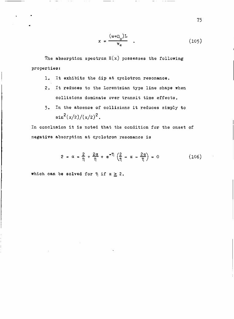
L
. 75
The absorption spectrum H(x) possesses the following
properties :
1. It exhibits the dip at cyclotron resonance.
2. It reduces to the Lorentzian type line shape when
collisions dominate over transit time effects.
3. In the absence of collisions it reduces simply t o
sin2 ( x/2 I/( x/2) 2.
In conclusion it is noted that the condition for the onset of
negative absorption at cyclotron resonance is
which can be solved for 7 if a 2 2 .
1.
2.
3.
4.
5.
6.
7.
8.
9.
10.
11 .
12 .
13 .
14
15 . 16.
17 .
References
R. Q. Twiss, Australian J. Phys. 11, 564 (1958).
G. Bekefi, J. L. Hirshfield and S. C. Brown, Phys. of Fluids
4, 173 (1961).
I. B. Bernstein, Phys. Hev. log, 10 (1958).
T, H. Stix, The Theory of Plasma Waves (McGraw-Hill Book
Company, New York, 1962).
D. C. Montgomery and D. A. Tidman, Plasma Kinetic Theory
(McGraw-Hill Book Company, New York, 1964) ,
E. S. Weibel, Phys. Rev. Lett. 2, 83 (1959). E. G. Harris, J. Nucl. Energy, Part C, 2, 138 (1961).
E. P. Gross, Phys. Rev. 82, 232 (1951).
H. Weitzner, Phys. of Fluids 6 , 1123 (1963). L. Landau, J. Physics U.S.S.R. l0, 25 (1946).
I. B. Bernstein, S. K. Trehan and M. P. H, Weenink, Nuclear
Fusion 4, 61 (1964).
G. Bekefi, Radiation Processes in Plasma (John Wiley and
Sons, New York, 1966).
Y. Terumichi, T. Idehara, I. Takahashi, H. Kubo and K.
Mitani, J. Phys. SOC, Japan 20, 1705 (1965).
P. L. Bhatnagar, E. P, Gross and El. book, Phys. Rev. 3,
511 (1954).
R. B. Brode, Rev. Mod. Phys. 5, 257 (1933). R. Wingerson, Phys. Rev. Lett. 6 , 446 (1961). H. Dreicer, H. J. Karr, E. A . Knapp, J. A. Phillips, E. J .
Stovall Jr. and J. L. Tuck, Nuclear Fusion, Supplement,
Part I, 299 (1962).

18. H. Karr, E. Knapp and W. Riesen
501 (1963)
\
3ld, Phys. o
77
Fluids, 6 ,
19. T. G. Northrop, The Adiabatic Motion of Charged Particles
(Interscience Publishers, Inc., New York, 1963).
20 .
21.
22.
23 0
24
25
26.
27.
28.
29 . 30
3 1
32
S. Chandrasekhar, Plasma Physics (University of Chicago
Press, Chicago, 1960).
F. Rosebury, Handbook of Electron Tube and Vacuum Techniques
(Addison-Wesley Publishing Co., Reading, Mass. , 1965). N. Bloembergen, E. M. Purcell and R. V. Pound, Phys. Rev.
E, 679 (1948) J. P. Gordon, Rev. of Scientific Instruments 2, 658 (1961). J. E. Drummond, Phys. Rev. 110, 293 (1958).
J. D. Jackson, Classical Electrodynamics (John Wiley and
Sons, New York, 1962), pp. 468-472.
H. Goldstein, Classical Mechanics (Addison-Wesley Publishing
Company, Reading, Mass., 1959) , pp. 266-268. E. H. Kennard, Kinetic Theory of Gases (McGraw-Hill Book
Company, New York, 1938).
E. A . Desloge and S. W. Matthysse, Am. J. Phys. 28, 1 (1960). S. Tanaka and K. Mitani, J. Phys. SOC. Japan x, 1376 (1964). Y. Terumichi, T. Idehara, S. Takahashi, H. Kubo and K.
Mitani, J. Phys. S O C . Japan 1p, 1993 (1964).
H. Fields, G. Bekefi and S. C. Brown, Phys. Rev. 129, 506
(1963 1 L. S. Frost and A. V. Phelps, Phys. Rev. 1_36, 1538 (1964).
i