6 m Monoband Conversion for Heathkit SB-1000 Amplifier · 2016-03-30 · Ron Berry, WB3LHD 326...
5
QEX May/June 2016 3 Ron Berry, WB3LHD 326 Sunset Drive, Bethel Park, PA 15102-1442: [email protected] 6 m Monoband Conversion for Heathkit SB-1000 Amplifier Convert this classic HF amplifier into a 6-m band work horse. 1 Notes appear on page 7 After 38 years of chasing DX on the HF bands, I decided it was time to explore a new frontier and push the 50 MHz button on my transceiver. I eagerly erected a 6 m two element quad antenna and started working some Maidenhead grid squares. 1 I soon realized that a bigger antenna and more than 100 W of power would be most helpful. I could afford a bigger antenna, but purchasing a 6 meter amplifier would be difficult. This would be the perfect time to convert my old Heathkit SB‑1000 amplifier to 6 meter operation. I had retired it 13 years ago from HF duty because of a twice‑blown band switch. It has been sleeping in my closet ever since. Since I was not an expert on the subject of amplifier conversions, and this was my first attempt, I felt it best to contact other hams who made the conversion successfully. I also consulted the ARRL Handbook, RF amplifier books, articles in QST, and searched the Internet for additional information. 2 Now confident, I began my HF to 6 meters amplifier conversion. For convenience, I assigned the components with alpha‑numeric designators directly from the original Heathkit SB‑1000 amplifier schematic. You can download the complete manual from the Internet. 3 Figure 1 shows the schematic diagram of my amplifier. I needed to address the following details during my conversion: strip the RF deck, change the plate and loading capacitors, modify the p‑input circuit and p‑L output circuit, replace the parasitic choke, replace the blocking capacitor, and replace the RF plate choke. I also replaced the internal RF output coax and safety choke. First, I removed the amplifier cover, knobs, vernier pointers, and lowered the front panel. I saved all the hardware and parts in small plastic cups and labeled sandwich bags as I removed them. This saved me a lot of trouble later on. I didn’t have to guess what screws or parts went where. Here are the details. Stripping the RF Deck With reference to the original schematic from the Heathkit SB‑1000 manual, carefully remove V1, the 3‑500Z tube, and set it aside. Remove the tank coils L7 and L8, inductor L9, plate RF choke RFC3, safety choke RFC1, door‑knob capacitors C26, C28 and C29, plastic standoffs, the band switch SW2, and the switch enclosure. When you remove the band switch enclosure do not cut off the input matching section mini coax cables that pass through the grommet. Unsolder those cables to keep them as long as possible, they will be used again. Mark the cables as input and output so you don’t get them reversed later. The input coax originates from pin 6 of relay K1, and the output coax connects to the 3‑500Z cathode capacitors C18 and C19. Remove the band switch with all the capacitors, and the tunable slug inductors from the enclosure, except L6, the original 10 m inductor. L6 is the inductor with the least number of turns on it, and is located at the top next to the grommet hole. We will modify and reuse inductor L6 as described later in the “p input circuit” section. Plate and Loading Capacitors The plate and loading variable capacitors must be replaced but you can swap the upper plate capacitor for the bottom loading capacitor. First remove the bottom loading capacitor C31 and set it aside for another project. Now remove the top plate capacitor C27 and mount it in the bottom loading capacitor position. When doing this you must reuse the original front mounting hole and drill a new rear mounting hole. Before you measure and drill the new rear hole, be sure the capacitor shaft is fully set into the vernier drive and is straight. A new upper plate capacitor will require less capacitance than the original, and a higher voltage rating. I purchased a Cardwell #154‑11‑1 (9 – 38 pF) 4 kV air variable capacitor. There are several sources for these and they vary greatly in price. To mount it, you must reuse the rear mounting hole and drill a new front mounting hole. Be careful when drilling the hole, as the high voltage power supply is directly behind the panel. Again, make sure that you mount the capacitor straight. The newly mounted Cardwell capacitor has the same shaft height as the original capacitor, but the shaft will not reach the vernier drive. To fix that, I purchased a piece of 0.25 inch O.D. aluminum shaft. I cut off a piece approximately 2.5 inches long, and connected the two shafts together using a coupler that I had in my junk box. Before you cut the aluminum shaft, measure it carefully to be sure it’s long enough to fit fully into the coupler and into the vernier drive. The p Input Circuit The original Heathkit input matching circuit is a p‑type configuration that uses a variable inductor and two fixed capacitors. Some hams have opted to modify their 6 m conversions to a T‑type network that has a variable capacitor and two fixed inductors. I wanted to retain the p circuit for its superior harmonic suppression and
Transcript of 6 m Monoband Conversion for Heathkit SB-1000 Amplifier · 2016-03-30 · Ron Berry, WB3LHD 326...

QEX May/June 2016 3
Ron Berry, WB3LHD
326 Sunset Drive, Bethel Park, PA 15102-1442: [email protected]
6 m Monoband Conversion for Heathkit SB-1000 AmplifierConvert this classic HF amplifier into a 6-m band work horse.
1Notes appear on page 7
After 38 years of chasing DX on the HF bands, I decided it was time to explore a new frontier and push the 50 MHz button on my transceiver. I eagerly erected a 6 m two element quad antenna and started working some Maidenhead grid squares.1 I soon realized that a bigger antenna and more than 100 W of power would be most helpful. I could afford a bigger antenna, but purchasing a 6 meter amplifier would be difficult. This would be the perfect time to convert my old Heathkit SB‑1000 amplifier to 6 meter operation. I had retired it 13 years ago from HF duty because of a twice‑blown band switch. It has been sleeping in my closet ever since.
Since I was not an expert on the subject of amplifier conversions, and this was my first attempt, I felt it best to contact other hams who made the conversion successfully. I also consulted the ARRL Handbook, RF amplifier books, articles in QST, and searched the Internet for additional information.2 Now confident, I began my HF to 6 meters amplifier conversion.
For convenience, I assigned the components with alpha‑numeric designators directly from the original Heathkit SB‑1000 amplifier schematic. You can download the complete manual from the Internet.3 Figure 1 shows the schematic diagram of my amplifier.
I needed to address the following details during my conversion: strip the RF deck, change the plate and loading capacitors, modify the p‑input circuit and p‑L output circuit, replace the parasitic choke, replace the blocking capacitor, and replace the RF plate choke. I also replaced the internal RF
output coax and safety choke. First, I removed the amplifier cover,
knobs, vernier pointers, and lowered the front panel. I saved all the hardware and parts in small plastic cups and labeled sandwich bags as I removed them. This saved me a lot of trouble later on. I didn’t have to guess what screws or parts went where. Here are the details.
Stripping the RF DeckWith reference to the original schematic
from the Heathkit SB‑1000 manual, carefully remove V1, the 3‑500Z tube, and set it aside. Remove the tank coils L7 and L8, inductor L9, plate RF choke RFC3, safety choke RFC1, door‑knob capacitors C26, C28 and C29, plastic standoffs, the band switch SW2, and the switch enclosure. When you remove the band switch enclosure do not cut off the input matching section mini coax cables that pass through the grommet. Unsolder those cables to keep them as long as possible, they will be used again. Mark the cables as input and output so you don’t get them reversed later. The input coax originates from pin 6 of relay K1, and the output coax connects to the 3‑500Z cathode capacitors C18 and C19. Remove the band switch with all the capacitors, and the tunable slug inductors from the enclosure, except L6, the original 10 m inductor. L6 is the inductor with the least number of turns on it, and is located at the top next to the grommet hole. We will modify and reuse inductor L6 as described later in the “p input circuit” section.
Plate and Loading CapacitorsThe plate and loading variable capacitors
must be replaced but you can swap the upper plate capacitor for the bottom loading
capacitor. First remove the bottom loading capacitor C31 and set it aside for another project. Now remove the top plate capacitor C27 and mount it in the bottom loading capacitor position. When doing this you must reuse the original front mounting hole and drill a new rear mounting hole. Before you measure and drill the new rear hole, be sure the capacitor shaft is fully set into the vernier drive and is straight.
A new upper plate capacitor will require less capacitance than the original, and a higher voltage rating. I purchased a Cardwell #154‑11‑1 (9 – 38 pF) 4 kV air variable capacitor. There are several sources for these and they vary greatly in price. To mount it, you must reuse the rear mounting hole and drill a new front mounting hole. Be careful when drilling the hole, as the high voltage power supply is directly behind the panel. Again, make sure that you mount the capacitor straight. The newly mounted Cardwell capacitor has the same shaft height as the original capacitor, but the shaft will not reach the vernier drive. To fix that, I purchased a piece of 0.25 inch O.D. aluminum shaft. I cut off a piece approximately 2.5 inches long, and connected the two shafts together using a coupler that I had in my junk box. Before you cut the aluminum shaft, measure it carefully to be sure it’s long enough to fit fully into the coupler and into the vernier drive.
The p Input CircuitThe original Heathkit input matching
circuit is a p‑type configuration that uses a variable inductor and two fixed capacitors. Some hams have opted to modify their 6 m conversions to a T‑type network that has a variable capacitor and two fixed inductors. I wanted to retain the p circuit for its superior harmonic suppression and
4 QEX May/June 2016
improved efficiency. I also decided to make it broadband enough to cover the entire 6 m band. This way no adjustments would be necessary with changes in frequency, and I could keep the original enclosure without the band switch. I started by modeling the circuit using an online Input Impedance Matching Designer.4
In Designer, enter 50 W for Source Resistance, 110 W for Load Resistance, 52 MHz for Frequency, and Desired Q of 2. Source Resistance is the exciter output impedance, Load Resistance is the 3‑500Z input impedance, and Q determines bandwidth of the circuit. After modeling the circuit, I built and tested it using a HP network analyzer. I added a 10 pF capacitor in parallel with the 110 W resistor at the output of the circuit to better simulate the 3‑500Z input impedance. The final circuit has the following values: C16 is 75 pF, L6 is 0.138 mH, C17 is 62 pF. I measured less than 0.2 dB insertion loss, and return loss greater than 30 dB, which is equivalent to a VSWR of less than 1.1:1 across the entire 50 – 54 MHz span of the 6 m band.
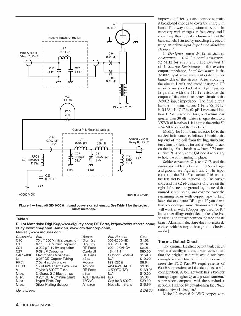
Modify the 10 m band inductor L6 to the needed inductance as follows. Unsolder the top end of the coil from the lug, undo one turn, trim it to length, tin and re‑solder it back on the lug. You should now have 2.75 turns (Figure 2). Apply some Q‑Dope if necessary to hold the coil winding in place.
Solder capacitors C16 and C17, and the mini‑coax cables between the L6 coil lugs and ground, see Figures 1 and 2. The input coax and the 75 pF capacitor C16 are on the left and below inductor L6. The output coax and the 62 pF capacitor C17 are on the right. I fastened the ground lug to one of the unused screw holes, and covered over the remaining holes with copper tape to help keep the enclosure RF tight. If you don’t have copper tape, some aluminum duct tape will work as well. [Copper tape used for RF has copper filings embedded in the adhesive, so there is dc contact between the tape and its target. Aluminum duct tape does not make dc contact with its target through the adhesive — Ed.].
The p‑L Output CircuitThe original Heathkit output tank circuit
was a p configuration. I was concerned that the original p circuit would not have enough second harmonic suppression to meet the FCC Part 97 requirements of 60 dB suppression, so I decided to use a p‑L configuration. A p‑L network has a broader tuning range, higher Q, and greater harmonic suppression compared with the standard p network. I started by downloading the PI-EL output network designer.5
Make L2 from #12 AWG copper wire
QX1605-Berry01
Input Coax toRelay K1, Pin 6
Output Coax toRelay K1, Pin 2
Input PI Matching Section
C1675 pF
C1762 pF
L60.138 μH C18
0.01 μF
C190.01 μF
Filament To T1
RFC1Z-507 μH
L2330 nH
L10.200 μH
C240.002 μF
10 kV
C3120-250 pF1 kV
C279-18 pF5 kV
C230.01 μF
B+~3000 V DC
47 Ω2 W
PC11 Turn
Output PI-L Matching Section
Plate Load
RFC342 Turns #24
1" Dia.
V13-500Z
Figure 1 — Heathkit SB‑1000 6 m band conversion schematic. See Table 1 for the project bill of materials.
Table 1.Bill of Materials: Digi‑Key, www.digikey.com; RF Parts, https://www.rfparts.com/; eBay, www.ebay.com; Amidon, www.amidoncorp.com/, Mouser, www.mouser.com. Description Part Source Part Number CostC16 75 pF 500 V mica capacitor Digi-Key 338-2835-ND $1.82C17 62 pF 500 V mica capacitor Digi-Key 338-2833-ND $1.82C24 0.002 mF 10 kV capacitor RF Parts 002-10KVHDA $2.95C27 9-38 pF Capacitor Cardwell 154-11-1 $50.00C401-408 Electrolytic Capacitors RF Parts CGS211T450R4 $159.60L1 0.25” OD Copper Tubing eBay N/A $10.00RFC1 7.0 mH safety choke Mouser 588-Z50E $5.61RFC3 15’ of #24 Thermaleze wire Amidon AWG#24 HAPT $3.00V1 Taylor 3-500ZG Tube RF Parts 3-500ZG-TAY $169.95Misc. Q-Dope, GC Electronics eBay N/A $10.00Misc. 0.25” OD Aluminum Shaft ACE Hardware N/A $5.00Misc. Hyper Plate Cap 73CNC Cap for 3-500Z $39.99Misc. Silver Plating Solution Amazon Medallion Brand $16.99
My total cost $476.73

QEX May/June 2016 5
stripped from a piece of 12‑2 Romex®. Wind four turns, 0.75 inches long around a one inch O.D. form. The inductance of L2 should be about 330 nH. One end connects to the load capacitor and the other end to the RF output coax center lead and the safety choke. I had a ceramic standoff insulator in my junk box to secure and insulate these connections, see Figure 3.
I made L1 from 0.25 inch O.D. thin wall copper tubing. Thin wall tubing is much easier to form than solid conductor. Wind five turns, five inches long, around a 1.50 inch O.D. form, see Figure 4. A video I saw on YouTube suggested to fill the tubing with table salt and crimp the ends tightly. The salt will prevent the coil from flattening and kinking as you wind it. Be sure to knock the salt out when finished. I cut the ends to length and mashed them flat with a hammer. I then drilled holes in the flats and fastened the ends between the variable capacitors. The inductance of the finished coil will be around 0.20 mH. I silver‑plated the coil with silver plating solution.6 This not only looks nice, but will help make it as efficient as possible.
The Parasitic ChokeThe original parasitic choke PC1 was
4.5 turns of wire wound around a 100 W 2 W resistor and was designed for an HF amplifier. I tried replacing it with four turns on a 47 W 2 W resistor. I measured a reactance of 16 W at 54 MHz. I felt the choke was far too aggressive so I wound a more 6 m friendly version. It has only one turn of #16 AWG buss wire wound around the 47 W 2 W resistor. This presented 1 W of reactance at 54 MHz but still has enough roll‑off above the 6 m band to be an effective parasitic choke.
The Blocking CapacitorI wanted a higher voltage rating on the
blocking capacitor to provide a higher margin of safety, so I replaced the original two‑parallel 0.001 mF 6 kV blocking capacitors C24 and C25 with a single 0.002 mF 10 kV, capacitor C24 (Figure 1).
RF Plate ChokeThe original RF plate choke RFC3
measured 120 mH inductance, which has good reactance for the HF bands, but way more than necessary for 6 m, and it might have a self‑resonance somewhere within the 6 m band. I removed all the original coil wires but reused the original 1 inch diameter ceramic form. I close‑wound 42 turns of #24 AWG heavy armored polythermaleze top‑coated (HAPT) magnet wire about 0.25 inches down from the top, and secured the coil turns to the ceramic form with
Figure 2 — Modified inductor L6 and routing of the input coax (left) and output coax (right). Capacitors C16 (left) and C17 are below L6.
Figure 3 — Inductor L2 mounts on a ceramic stand‑off and connects to the RF output coax (below and left) and to choke RFC1. The other end of RFC1, and the coax shield connect to
the ground lug at the bottom.

6 QEX May/June 2016
Q‑Dope. The finished inductor measured around 30 mH. Fasten the choke back into position (Figure 4) with the bottom screw and re‑solder the red high voltage lead, the 0.001 mF capacitor C23, and the bottom choke wire to the bottom lug. Screw the top solder lug in place and solder the new parasitic choke PC1, the new blocking capacitor, and the top choke wire.
The RF Output CoaxThe original type RG‑58 output coax is
marginal at 50 MHz for more than 500 W, so I replaced it with a section of 50 W RG‑142 TeflonTM dielectric coax. Teflon has a much higher breakdown voltage rating than polyethylene. A section of RG‑213 or RG‑8 coax would work as well but because of its larger diameter you may have difficulty
routing it around. The coax center lead attaches to the end of L2 where the safety choke attaches. The shield attaches to a solder lug on the chassis ground, (Figure 3).
The Safety ChokeI replaced the original safety choke
RFC1 with an Ohmite Z50 7 mH choke. The safety choke is there in case the dc blocking capacitor C24 shorts. This would place thousands of plate volts to your antenna system, possibly causing damage and potentially killing someone. The safety choke has high reactance at RF but is a dc short to ground. In the event that the blocking capacitor shorts, the safety choke shorts the 3,000 V plate supply to ground, rather than to your antenna system. This will cause the amplifier fuse to blow, stopping the threat. The safety choke attaches between L2 where the RF output coax attaches, and chassis ground as seen in Figure 3.
Putting It Back TogetherFollow the procedure in the Heathkit
manual when setting the vernier drive pointer position in relation to the capacitor rotor shafts. Carefully look around to be sure you didn’t leave any hardware or cut‑off wires laying around the chassis. The amplifier conversion is finished and should look similar to the views in Figures 4 and 5.
Reinstall the front cover and install the plate and load capacitor knobs. I wanted to have a clean looking front panel, so I retained the original lettering and knob indication. I installed a hole plug into the hole of the missing band switch, and added a “SIX METER AMPLIFIER”, and a “6 METER” label for the band switch on the front panel as seen in Figure 6. You can, of course, repaint or label your front panel as you wish.
Input Matching Alignment
Turn the amplifier on, and follow the Heathkit manual alignment procedure on pages 55 and 56 of the Heathkit SB‑1000 manual. In my case, I set the PLATE capacitor to approximately the two o’clock position and the LOAD capacitor to approximately 7. I tuned my exciter to 52 MHz and adjusted the p input matching inductor L6 for minimum VSWR. I achieved a perfect 1:1 match. The design bandwidth Q of 2 is broad banded enough to cover the entire 50‑54 MHz band without any farther adjustments. Just set it, and forget it!
Final Tune, Final WordsMy amplifier tunes up nicely without any
surprises and delivers 650 W with 50 to 60 W of drive across the 6 m band. On air reports
Figure 4 —Your finished modifications should resemble the parts placement seen in this view.
Figure 5 — Another internal view of the finished converted amplifier.

QEX May/June 2016 7
Figure 6 — Front panel of the modified Heathkit amplifier.
verified that it is clean and without distortion. I noted the following PLATE and LOAD front panel capacitor settings,
•50 MHz: PLATE at the two o’clock position, LOAD at 7.0,
•54 MHz: PLATE at the three o’clock position, LOAD at 8.0.
The original Eimac 3‑500Z that came with my Heathkit was 27 years old and showed the dreaded gassy blue halo on first power up. I replaced it with a new 3‑500ZG graphite tube. I also wanted the new tube to run as cool as possible, so I purchased a Hyper Plate Cap from 73CNC.7 As a precaution, I also replaced the eight 210 mF 450 V dc electrolytic capacitors, C401 – C408, on the high voltage power supply board. It was an expensive replacement but I felt it was good insurance considering the age of the original capacitors.
If you follow these instructions and layout exactly, you should not have any problems. The total cost for my conversion was about $477, see the bill of materials in Table 1. You may not need to purchase everything I did, so you could conceivably do your conversion for a much lower cost.
Safety Note: please keep in mind that there is 3,000 V dc at the power supply and the tube plate circuit. Contact could be lethal, so please use caution, and NEVER turn on the amplifier with the cover completely off and with the ac interlock defeated.
ConclusionThis conversion took me many months and
several iterations to complete successfully. The amplifier operates at a calculated efficiency of 45%. This was a low‑cost and fun project for me, and I’m happy with the 650 W RF output. That’s more than 8 dB advantage over my original 100 W.
If you have an old Heathkit SB‑1000 sleeping in your closet, wake it up and give it new life! Good luck and I hope to work you on the Magic Band!
I extend my thanks to the hams whose great advice helped me with this project, and especially to Terry Osborn, K8SMC, Bob Unetich, K3NSC, Mike Penkas, WA8EBM, and John Nogan, AB5Q.
Ron Berry, WB3LHD, holds an Amateur Extra class license. He graduated from electronic school in 1969 with a degree in electronics technology. He has been an electronic technician for 47 years working in the TV broadcast industry for ITS Corporation, ADC Telecommunications and Axcera LLC, in Engineering and in the test department
performing transmitter final calibration. Ron is now semi-retired working at GigaHertz, LLC in the Engineering Department as an RF Engineering Technician. He is President of the GigaHertz Radio Club, K3ITS.
Ron’s main interest is working DX using CW, SSB, RTTY, and other digital modes. He is on the DXCC Honor Roll and needs just 3 entities to achieve DXCC #1. Ron has been a ham and ARRL member for 38 years, and a member of INDEXA and SMIRK. Two of his most memorable events were visiting ARRL headquarters in 1994, and operating RTTY from his home station as W1AW/3 in the 2014 ARRL Centennial Celebration.
Notes1Maidenhead Locator System, see www.arrl.
org/grid‑squares. 2The ARRL Handbook, 2016 Edition, Available
from your ARRL dealer or the ARRL book-store, ARRL item number 0413 or 0420. Telephone 860-594-0355, or toll free in the US 888-277-5289; www.arrl.org/shop; [email protected].
3Heathkit SB-1000 manual and schematic, www.vintage‑radio.info/heathkit.
4See home.sandiego.edu/~ekim/e194rfs01/jwmatcher/matcher2.html.
5PI-EL output matching designer www.ton‑nesoftware.com/piel.html.
6Silver plating solution from, www.medal‑lioncare.com.
773CNC, see www.73cnc.com/default.asp.