6. Gear Measurement And Testingmitpolytechnic.ac.in/downlaods/09_knowledge-bank/04...•This uses a...
52
6. Gear Measurement And Testing
Transcript of 6. Gear Measurement And Testingmitpolytechnic.ac.in/downlaods/09_knowledge-bank/04...•This uses a...

6. Gear Measurement And Testing

Introduction • Gears are mainly used for transmission of
power and motion.
• They are used in various automobiles,
machines, equipments, electronic systems, etc.
• We already know that gears are used for
decreasing or increasing speed.
• They are also used for changing direction of
motion.

Types of Gears • Spur Gear : It is a cylindrical gear whose tooth
traces are straight lines.
• Helical Gear : It is a cylindrical gear whose tooth traces are straight helices.
• Spiral Gear : A gear whose tooth traces are curved lines.
• Straight Bevel : A gear whose tooth traces are straight line generators of a cone. It is Gear conical in form operating on intersecting axes usually at angles.
• Worm Gear Pair: The worm and mating worm wheel have their axes non-parallel and non-intersecting.

Terminology of Spur Gear

• Base Circle - It is the circle from which involute form is generated. Only the base circle on a gear is fixed and unalterable.
• Pitch Circle - It is an imaginary circle most useful in calculations. It may be noted that an infinite number of pitch circles can be chosen, each associated with its own pressure angle.
• Pitch Circle Diameter (P.C.D.) - It is the diameter of a circle which by pure rolling action would produce the same motion as the toothed gear wheel. This is the most important diameter in gears.

• Module - It is defined as the length of the pitch circle diameter per tooth. Thus if P.C.D. of gear be D and number of teeth N, then module (m) = D/N.
It is generally expressed in mm.
• Diametral Pitch - It is expressed as the number of teeth per inch of the P.C.D.
Diametral Pitch = 1/m = N/Dpitch
• Circular Pitch (CP.) - It is the arc distance measured around the pitch circle from the flank of one tooth to a similar flank in the next tooth. .-. CP. = πD/N = πm
• Addendum - This is the radial distance from the pitch circle to the tip of the tooth. Its value is equal to one module.
• Clearance - This is the radial distance from the tip of a tooth to the bottom of a mating tooth space when the teeth are symmetrically engaged. Its standard value is 0.157 m.

• Dedendum - This is the radial distance from the pitch circle to the bottom of the tooth space. Dedendum = Addendum + Clearance
= m + 0.157m = 1.157m.
• Tooth Thickness - This is the arc distance measured along the pitch circle from its intercept with one flank to its intercept with the other flank of the same tooth. Normally tooth thickness = C.P./2 = πm/2 But thickness is usually reduced by certain amount to allow for some amount of backlash and also owing to addendum correction.

• Face of Tooth. It is that part of the tooth surface which is above the pitch surface.
• Flank of Tooth. It is that part of the tooth surface which is lying below the pitch surface.
• Pressure Angle – It is the angle between path of contact and normal drawn to the line joining centers of base circle.
• Helix Angle : It is the acute angle between the tangent to the helix and axis of the cylinder on which teeth are cut.
• Lead Angle : It is the acute angle between the tangent to the helix and plane perpendicular to the axis of cylinder
• Back Lash : The distance through which a gear can be rotated to bring its non-working flank in contact with the teeth of mating gear.


Analytical Inspection of Gears
• Gear manufacturing process involves various
steps which may need in process inspection.
• A gear blank, at starting of an operation should
be checked for dimensional accuracy of face
width, bore, length, diameter, etc.
• The analytical method of gear involves
checking of various parameters of an
individual gear.
• It involves checking concentricity of gear
teeth, alignment of each tooth, hardness of
gear blank, etc.
• It also involves the factor that involves accuracy
of measurement of these parameter.
• Analytical method is tedious and it is not
preferred by industries because the values of
errors in pitch, profile cannot give the error of
overall operation of the gear.
• The analytical method is of useful for students
for study and to understand the concept.
• It will be useful for research and development
work in industries and laboratories.

Functional Method • It involves, mainly checking of gear running with
another gear during operation or at actual work.
• For testing function of gear, master gear is used in
combination of manufactured gear.
• Functional method is used for determining composite
errors in vibration, noise during working of gear.
• If the gear does not satisfy the rolling test, individual
or analytical test is carried out.
• To carry out functional test of the gear, Parkinson
gear tester or automating gear rolling machines are
used.

Rolling Test • Rolling test of gears give the composite error analysis
of gears.
• In rolling test, gear to be tested is rolled with the
master gear.
• This test reveals any errors in tooth form, pitch and
concentricity of the pitch line.
• This is the fact, economical and accurate method of
gear testing.
• Results of rolling test of gears are carefully observed
and conclusions are drawn regarding the angular
rotation per teeth, eccentricity as the error, individual
tooth error, etc.

Measurement of tooth thickness by gear tooth
vernier calliper


• It is used to measure the thickness of gear teeth
at the pitch line or chordal thickness of teeth and
the distance from the top of a tooth to the chord.
• The thickness of a tooth at pitch line and the
addendum is measured by an adjustable tongue,
each of which is adjusted independently by
adjusting screw on graduated bars.
• The effect of zero errors should be taken into
consideration.
• This method is simple and inexpensive.

• However it needs different setting for a
variation in number of teeth for a given
pitch and accuracy is limited by the least
count of instrument.
• Since the wear during use is concentrated
on the two jaws, the calliper has to be
calibrated at regular intervals to maintain
the accuracy of measurement.


• The tooth thickness is generally measured at
pitch circle and is, therefore, referred to as
pitch-line thickness of tooth.
• The gear tooth vernier has two vernier scales
and they are set for the width (w) of the tooth
and the depth (d) from the top, at which w
occurs.
Considering one gear tooth, the theoretical
values of w and d can be found out which may
be verified by the instrument.

• In Fig. 15.14, it may be noted that w is a chord
ADB, but tooth thickness is specified as an arc
distance AEB.
• Also the distance d adjusted on instrument is
slightly greater than the addendum CE, w is
therefore called chordal thickness and d is
called the chordal addendum.

• In the above sketch ‘d’ is chordal addendum
which can be calculated as –
d = [(N × m)/2]×[1+(2/N)-cos(90/N)]
N – Number of teeth
M – module
• Tooth thickness can be calculated using gear
tooth vernier.
• By setting ‘d’ in vertical vernier, horizontal
vernier gives ‘w’ and can be verified by –
w = N × m sin(90/N)
Measurement of tooth thickness by Constant
Chord Method.
• In the above method, it is seen that both the
chordal thickness and chordal addendum are
dependent upon the number of teeth.
• Hence for measuring a large number of gears
for set, each having different number of teeth
would involve separate calculations, thus the
procedure becomes tedious and time-
consuming one.

• The constant chord method does away with
these difficulties.
• Constant chord of a gear is measured where
the tooth flanks touch the flanks of the basic
rack.
• The teeth of the rack are straight and inclined
to their centre lines at the pressure angle as
shown in Fig


• Also the pitch line of the rack is tangential to
the pitch circle of the gear and,- by definition,
the tooth thickness of the rack along this line is
equal to the arc tooth thickness of the gear
round its pitch circle.
• Now, since the gear tooth and rack space are in
contact in the symmetrical position at the
points of contact of the flanks, the chord is
constant at this position irrespective of the gear
of the system in mesh with the rack.

• The measurement of tooth thickness at
constant chord simplified the problem for all
number of teeth.
• If an involutes tooth is considered
symmetrically in close mesh with a basic rack
form, then it will be observed that regardless
of the number of teeth for a given size of tooth
(same module), the contact always occurs at
two fixed point A and B. AB is known as
constant chord.

• The constant chord is defined as the chord joining those
points, on opposite faces of the tooth, which make
contact with the mating teeth when the centre line of the
tooth lies on the line of the gear centers.
• The value of AB and its depth from the tip, where it
occurs can be calculated mathematically and then
verified by an instrument.
• The advantage of the constant chord method is that for
all number of teeth (of same module) value of constant
chord is same.
• In other words, the value of constant chord is constant
for all gears of a meshing system.
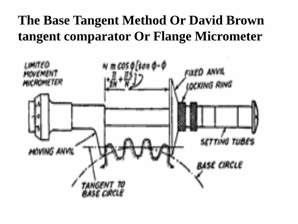
The Base Tangent Method Or David Brown
tangent comparator Or Flange Micrometer

• The purpose of tangent tester is to determine the
mean value and variation in base tangent length.
• It is measured between two parallel measuring
surfaces tangential to unlike gear teeth falnk.
• In this method, the span of a convenient number of
teeth is measured with the help of the tangent
comparator.
• This uses a single vernier caliper and has, therefore,
the following advantages over gear tooth vernier
which used two vernier scales :
(i) the measurements do not depend on two vernier
readings, each being function of the
other.

(ii) the measurement is not made with an edge of
the measuring jaw with the face. Consider a
straight generator (edge) ABC being rolled back
and forth along a base circle.
• The tangent length can be calculated as –
d = N × m – cos ø [tan ø – ø – (pia/2N) + (pia S/N)
Where, N – Number of teeth
M – module
Ø – Pressure angle
S – No. of teeth between two anvils.
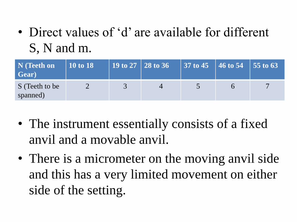
• Direct values of ‘d’ are available for different
S, N and m.
• The instrument essentially consists of a fixed
anvil and a movable anvil.
• There is a micrometer on the moving anvil side
and this has a very limited movement on either
side of the setting.
N (Teeth on
Gear)
10 to 18 19 to 27 28 to 36 37 to 45 46 to 54 55 to 63
S (Teeth to be
spanned)
2 3 4 5 6 7

• The distance is adjusted by setting the fixed
anvil at desired place with the help of looking
ring and setting tubes.
• The movable anvil can be also locked by using
slip gauges for setting proper calculate
distance.
• Difference of reading which is set and
measured can be calculated using micrometer.
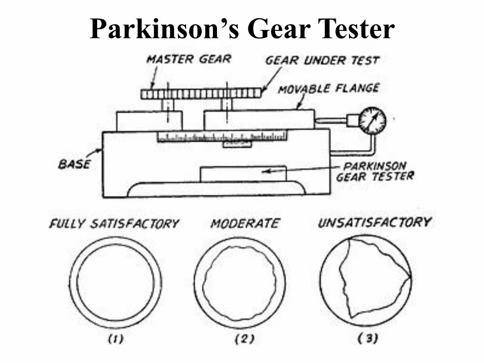
Parkinson’s Gear Tester


• The principle of this device is to mount a
standard gear on a fixed vertical spindle and the
gear to be tested on another similar spindle
mounted on a sliding carriage, maintaining the
gears in mesh by spring pressure.
• Movements of the sliding carriage as the gears
are rotated are indicated by a dial indicator, and
these variations are a measure of any
irregularities in the gear under test; alternatively
a recorder can be fitted, in the form of a waxed
circular chart and records made of the gear
variation in accuracy of mesh.

Construction • One fixed spindle and other movable spindle is
mounted on flat base.
• The movable spindle moves along with base
by rolling action on the main base plate as
shown in figure.
• A master gear is mounted on the fixed spindle
whereas a gear to be tested is mounted on a
movable spindle.
• The dial gauge is set to note the errors whose
pointer touches the floating body.

Working • When master gear is rotated slowly, a gear to
be tested will also get rotation movement
because of their meshing.
• Errors in the manufactured gear cause the gear
to move away from the centerline of spindle.
• When the on test moves, the floating body also
moves by the same distance. Because of
displacement of floating body, dial gauge gives
displacement.
• The variations in the readings can be observed
and platted in the graphical format.

Limitations • Maximum 300 mm diameter gears can be
tested.
• The floating body is very sensitive and hence
readings are to be taken very carefully.
• Accuracy up to 1µm can be possible while
measurement.
• Only composite errors in the gears can be
checked not individual one.
• Measurement depends upon the master gear.

Involute Measurement
• Involute is a curve plotted by a point on a
straight line which rolls around a circle
without slipping.
• Involute measurement is done by –
1) By profile projector
2) By Involute measuring machine

Involute Measuring Machine

• The basic principle of working is that if a straight
edge is rolled around a base circle without slipping,
the stylus of the dial gauge attached as above, gives
a involute.
• The gear to be tested is mounted on a mandrill.
• The circular disc of the same size as that of PCD is
also to be mounted on the same mandrill.
• The straight edge on the disc, which is tangent rolls
around the disc, generates a involute and the
variation is recorded by dial gauge.
• A electronics plotter can be used instead of dial
gauge for recording purpose.

Pitch Measuring Machine


• This instrument has three tips.
• One is the fixed measuring tip, other one is the
sensitive tip whose position can be adjusted by a
screw and the further movement of it is
transmitted through a leverage system to the dial
indicator and the third tip is the supplementary
adjustable stop which is meant for the stability of
the instrument and its position can also be
adjusted by a screw.
• The distance between the fixed and sensitive tip
is set to be equivalent to the base pitch of the
gear with the help of slip gauges.
• The properly set-up instrument is applied to
the gear so that all the three tips contact the
tooth profile.
• The reading on dial indicator is the error in the
base pitch.
Procedure of Measurement • The distance between tip (1) and (2) is set to a
standard using slip gauges when dial gauge is
showing a readings considered as zero.
• The machine is then applied to the gear under
test.
• All three tips are made contact to gear under
test.
• Reading of dial indicator shows the variation
in pitch.
• Repeat the procedure for next pair of gear
tooth.

Errors in Gear • Following are various gear errors that can be
checked while analytical inspection is carried out.
1) Profile 2) Spacing 3) Pitch 4) Run out 5) Gear
Tooth Thickness 6) Lead 7) Backlash.
The Errors are –
1) Cumulative pitch error
2) The tooth thickness error
3) Cyclic error
4) Run out
5) Radial Run out
6) Backlash

• Cumulative pitch error - It is defined as the
actual length between corresponding flanks of
teeth not adjacent to each other.
• The tooth thickness error – It is the difference
in actual tooth thickness and required tooth
thickness.
• Cyclic error - An error occurring during each
revolution of the element under consideration.
• Run out - It is the total range of reading of a
fixed indicator with the contact point applied to a
surface rotated, without axial movement about a
fixed axis.

• Radial Run out - It is the run-out measured
along a perpendicular to the axis of rotation.
• Backlash – It is the play between the matting
tooth surfaces i.e. the distance through which a
gear can be rotated to bring its nonworking
flank in contact to teeth of mating gear.
• Axial run-out (wobble) - It is the run-out
measured parallel to the axis of rotation, at a
specified distance from the axis.

? MSBTE QUESTIONS
• Describe with a neat sketch the use of Vernier
gear tooth caliper to measure the chordal
thickness of gear tooth on the pitch circle.
• Describe with neat sketch Parkinson gear tester.
• Explain principle of measurement of gear tooth
thickness using a gear tooth vernier.
• State and explain any four types of errors in
gear.
• Explain how will you check the involute profile
of a spur gear using involute measuring
machine.
• Explain following errors in gears
i) Backlash ii) Run out
Explain constant chord method for measuring tooth thickness of gear.