6-Compo Paper
12
Journal of Materials Processing Technology 238 (2016) 96–107 Contents lists available at ScienceDirect Journal of Materials Processing Technology jo ur nal home p ag e: www.elsevier.com/locate/jmatprotec Microstructure and mechanical properties of dissimilar pure copper foil/1050 aluminium composites made with composite metal foil manufacturing Javaid Butt ∗ , Habtom Mebrahtu, Hassan Shirvani Engineering & Built Environment, Anglia Ruskin University, Bishop Hall Lane, CM1 1SQ, Chelmsford, United Kingdom a r t i c l e i n f o Article history: Received 16 December 2015 Received in revised form 3 July 2016 Accepted 9 July 2016 Available online 11 July 2016 Keywords: Additive manufacturing Brazing Composite Laminated object manufacturing Lap shear test Peel test Tensile test a b s t r a c t In this paper, we present mechanical testing and microstructural analysis carried out on a number of layered composites of aluminium 1050 and pure copper foils. The parts were made by an additive manu- facturing process termed as Composite Metal Foil Manufacturing. It is a combination of Laminated Object Manufacturing and brazing. The effectiveness of the process is validated with lap shear testing, peel test- ing, microstructural analysis and tensile testing. Joining dissimilar metals is generally difficult but the process is capable of achieving this goal with ease. Tests were carried out on lap joints with varying thick- ness to assess the effect on the bond. Tensile lap shear strength was also calculated using thicker plates by observing cohesion failure. The peel test showed a good bond consistency in all the specimens with an average peel strength of 20 MPa. Microstructural analysis showed a large proportion of bonded area which is essential for proper bonding. Comparative tensile test was conducted among dog-bone spec- imens machined from solid aluminium 1050 block, copper block and composite Al/Cu specimen. The results showed that the specimen made by composite metal foil manufacturing fractured at a load value that is 11% higher than that of aluminium but lower than that of copper for the same overall thickness of the test specimens. This yielded a new composite that could be used for different applications based on its suitability. © 2016 Elsevier B.V. All rights reserved. 1. Introduction A large number of additive manufacturing (AM) processes are commercially available. Most of these processes use materials such as polymers, ceramics, metals etc., but the production of metal composites has been receiving unprecedented attention from academia, mainstream media, investment community and national governments around the world. Metal composites or metal matrix composites (MMCs) are gaining popularity because a num- ber of industries rely on them to provide cheaper, lighter, and stronger alternatives. There are a few additive manufacturing pro- cesses capable of producing metal composites, namely Selective Laser Melting/Sintering (SLM/SLS), Laser Engineered Net Shaping (LENS), Three Dimensional Printing (3DP), Laminated Object Man- ufacturing (LOM), and Ultrasonic Consolidation (UC). ∗ Corresponding author. E-mail addresses: [email protected] (J. Butt), [email protected] (H. Mebrahtu), [email protected] (H. Shirvani). SLM/SLS can produce composites by using three methods: (i) using various powders, (ii) in situ reactions, and (iii) furnace treatment. Using the first method, Simchi and Pohl (2004) have successfully sintered iron and graphite powder mixture to produce an extremely strong composite with comparative mechanical prop- erties to its parent metals. Laoui et al. (2000) studied the effect of alloying on selective laser sintering of WC-Co powder to enhance the mechanical properties of the resulting composite. Gu and Shen (2006) took the same work forward and reinforced Cu matrix to WC-Co using direct laser sintering. They also analysed the effect on the microstructure of the ultra-fine WC-Co particulate and found interlocking of the powder that gave the material its high strength. The research kept shifting from two materials to more so as to produce MMCs with totally different properties than the parent materials from which they were produced. This shift paved the way for Gaard et al. (2006) to produce (Fe, Ni)-TiC MMCs using DMLS. The powders were sintered together and the wear characteristics of the final product shows its potential uses in the industrial sector. The second method uses laser-induced chemical reactions to cre- ate in-situ particles during laser sintering. Slocombe and Li (2001) produced TiC-Al 2 O 3 composite from TiO 2 , Al and C by combining http://dx.doi.org/10.1016/j.jmatprotec.2016.07.014 0924-0136/© 2016 Elsevier B.V. All rights reserved.
-
Upload
javaid-butt -
Category
Documents
-
view
56 -
download
0
Transcript of 6-Compo Paper
Mfm
JE
a
ARRAA
KABCLLPT
1
csmfnmbscL(u
h(
h0
Journal of Materials Processing Technology 238 (2016) 96–107
Contents lists available at ScienceDirect
Journal of Materials Processing Technology
jo ur nal home p ag e: www.elsev ier .com/ locate / jmatprotec
icrostructure and mechanical properties of dissimilar pure copperoil/1050 aluminium composites made with composite metal foil
anufacturing
avaid Butt ∗, Habtom Mebrahtu, Hassan Shirvaningineering & Built Environment, Anglia Ruskin University, Bishop Hall Lane, CM1 1SQ, Chelmsford, United Kingdom
r t i c l e i n f o
rticle history:eceived 16 December 2015eceived in revised form 3 July 2016ccepted 9 July 2016vailable online 11 July 2016
eywords:dditive manufacturingrazingompositeaminated object manufacturing
a b s t r a c t
In this paper, we present mechanical testing and microstructural analysis carried out on a number oflayered composites of aluminium 1050 and pure copper foils. The parts were made by an additive manu-facturing process termed as Composite Metal Foil Manufacturing. It is a combination of Laminated ObjectManufacturing and brazing. The effectiveness of the process is validated with lap shear testing, peel test-ing, microstructural analysis and tensile testing. Joining dissimilar metals is generally difficult but theprocess is capable of achieving this goal with ease. Tests were carried out on lap joints with varying thick-ness to assess the effect on the bond. Tensile lap shear strength was also calculated using thicker platesby observing cohesion failure. The peel test showed a good bond consistency in all the specimens withan average peel strength of 20 MPa. Microstructural analysis showed a large proportion of bonded areawhich is essential for proper bonding. Comparative tensile test was conducted among dog-bone spec-
ap shear testeel testensile test
imens machined from solid aluminium 1050 block, copper block and composite Al/Cu specimen. Theresults showed that the specimen made by composite metal foil manufacturing fractured at a load valuethat is 11% higher than that of aluminium but lower than that of copper for the same overall thickness ofthe test specimens. This yielded a new composite that could be used for different applications based onits suitability.
© 2016 Elsevier B.V. All rights reserved.
. Introduction
A large number of additive manufacturing (AM) processes areommercially available. Most of these processes use materialsuch as polymers, ceramics, metals etc., but the production ofetal composites has been receiving unprecedented attention
rom academia, mainstream media, investment community andational governments around the world. Metal composites or metalatrix composites (MMCs) are gaining popularity because a num-
er of industries rely on them to provide cheaper, lighter, andtronger alternatives. There are a few additive manufacturing pro-esses capable of producing metal composites, namely Selective
aser Melting/Sintering (SLM/SLS), Laser Engineered Net ShapingLENS), Three Dimensional Printing (3DP), Laminated Object Man-facturing (LOM), and Ultrasonic Consolidation (UC).∗ Corresponding author.E-mail addresses: [email protected] (J. Butt),
[email protected] (H. Mebrahtu), [email protected]. Shirvani).
ttp://dx.doi.org/10.1016/j.jmatprotec.2016.07.014924-0136/© 2016 Elsevier B.V. All rights reserved.
SLM/SLS can produce composites by using three methods: (i)using various powders, (ii) in situ reactions, and (iii) furnacetreatment. Using the first method, Simchi and Pohl (2004) havesuccessfully sintered iron and graphite powder mixture to producean extremely strong composite with comparative mechanical prop-erties to its parent metals. Laoui et al. (2000) studied the effect ofalloying on selective laser sintering of WC-Co powder to enhancethe mechanical properties of the resulting composite. Gu and Shen(2006) took the same work forward and reinforced Cu matrix toWC-Co using direct laser sintering. They also analysed the effect onthe microstructure of the ultra-fine WC-Co particulate and foundinterlocking of the powder that gave the material its high strength.The research kept shifting from two materials to more so as toproduce MMCs with totally different properties than the parentmaterials from which they were produced. This shift paved the wayfor Gaard et al. (2006) to produce (Fe, Ni)-TiC MMCs using DMLS.The powders were sintered together and the wear characteristics
of the final product shows its potential uses in the industrial sector.The second method uses laser-induced chemical reactions to cre-ate in-situ particles during laser sintering. Slocombe and Li (2001)produced TiC-Al2O3 composite from TiO2, Al and C by combining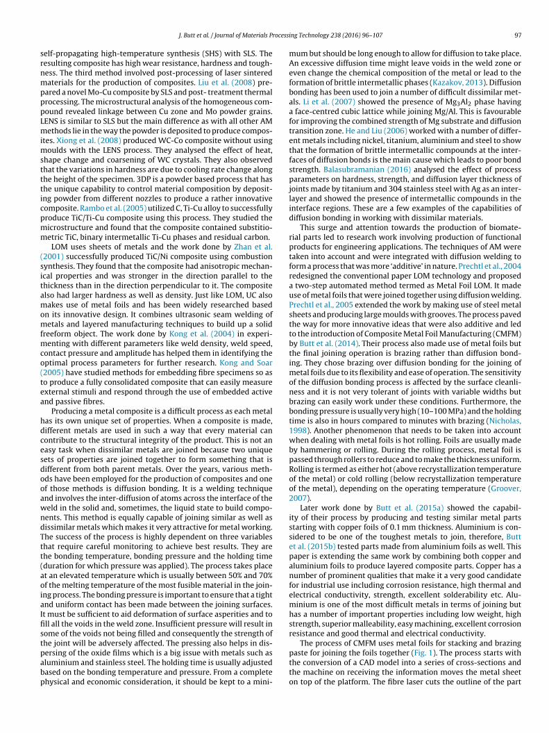
rocessi
srnmpppLmimsttticpmm
(sitamomfmco(tea
hdcesdooawndTtt(aoiaIfistpabp
J. Butt et al. / Journal of Materials P
elf-propagating high-temperature synthesis (SHS) with SLS. Theesulting composite has high wear resistance, hardness and tough-ess. The third method involved post-processing of laser sinteredaterials for the production of composites. Liu et al. (2008) pre-
ared a novel Mo-Cu composite by SLS and post- treatment thermalrocessing. The microstructural analysis of the homogeneous com-ound revealed linkage between Cu zone and Mo powder grains.ENS is similar to SLS but the main difference as with all other AMethods lie in the way the powder is deposited to produce compos-
tes. Xiong et al. (2008) produced WC-Co composite without usingoulds with the LENS process. They analysed the effect of heat,
hape change and coarsening of WC crystals. They also observedhat the variations in hardness are due to cooling rate change alonghe height of the specimen. 3DP is a powder based process that hashe unique capability to control material composition by deposit-ng powder from different nozzles to produce a rather innovativeomposite. Rambo et al. (2005) utilized C, Ti-Cu alloy to successfullyroduce TiC/Ti-Cu composite using this process. They studied theicrostructure and found that the composite contained substitio-etric TiC, binary intermetallic Ti-Cu phases and residual carbon.
LOM uses sheets of metals and the work done by Zhan et al.2001) successfully produced TiC/Ni composite using combustionynthesis. They found that the composite had anisotropic mechan-cal properties and was stronger in the direction parallel to thehickness than in the direction perpendicular to it. The compositelso had larger hardness as well as density. Just like LOM, UC alsoakes use of metal foils and has been widely researched based
n its innovative design. It combines ultrasonic seam welding ofetals and layered manufacturing techniques to build up a solid
reeform object. The work done by Kong et al. (2004) in experi-enting with different parameters like weld density, weld speed,
ontact pressure and amplitude has helped them in identifying theptimal process parameters for further research. Kong and Soar2005) have studied methods for embedding fibre specimens so aso produce a fully consolidated composite that can easily measurexternal stimuli and respond through the use of embedded activend passive fibres.
Producing a metal composite is a difficult process as each metalas its own unique set of properties. When a composite is made,ifferent metals are used in such a way that every material canontribute to the structural integrity of the product. This is not anasy task when dissimilar metals are joined because two uniqueets of properties are joined together to form something that isifferent from both parent metals. Over the years, various meth-ds have been employed for the production of composites and onef those methods is diffusion bonding. It is a welding techniquend involves the inter-diffusion of atoms across the interface of theeld in the solid and, sometimes, the liquid state to build compo-
ents. This method is equally capable of joining similar as well asissimilar metals which makes it very attractive for metal working.he success of the process is highly dependent on three variableshat require careful monitoring to achieve best results. They arehe bonding temperature, bonding pressure and the holding timeduration for which pressure was applied). The process takes placet an elevated temperature which is usually between 50% and 70%f the melting temperature of the most fusible material in the join-
ng process. The bonding pressure is important to ensure that a tightnd uniform contact has been made between the joining surfaces.t must be sufficient to aid deformation of surface asperities and toll all the voids in the weld zone. Insufficient pressure will result inome of the voids not being filled and consequently the strength ofhe joint will be adversely affected. The pressing also helps in dis-
ersing of the oxide films which is a big issue with metals such asluminium and stainless steel. The holding time is usually adjustedased on the bonding temperature and pressure. From a completehysical and economic consideration, it should be kept to a mini-ng Technology 238 (2016) 96–107 97
mum but should be long enough to allow for diffusion to take place.An excessive diffusion time might leave voids in the weld zone oreven change the chemical composition of the metal or lead to theformation of brittle intermetallic phases (Kazakov, 2013). Diffusionbonding has been used to join a number of difficult dissimilar met-als. Li et al. (2007) showed the presence of Mg3Al2 phase havinga face-centred cubic lattice while joining Mg/Al. This is favourablefor improving the combined strength of Mg substrate and diffusiontransition zone. He and Liu (2006) worked with a number of differ-ent metals including nickel, titanium, aluminium and steel to showthat the formation of brittle intermetallic compounds at the inter-faces of diffusion bonds is the main cause which leads to poor bondstrength. Balasubramanian (2016) analysed the effect of processparameters on hardness, strength, and diffusion layer thickness ofjoints made by titanium and 304 stainless steel with Ag as an inter-layer and showed the presence of intermetallic compounds in theinterface regions. These are a few examples of the capabilities ofdiffusion bonding in working with dissimilar materials.
This surge and attention towards the production of biomate-rial parts led to research work involving production of functionalproducts for engineering applications. The techniques of AM weretaken into account and were integrated with diffusion welding toform a process that was more ‘additive’ in nature. Prechtl et al., 2004redesigned the conventional paper LOM technology and proposeda two-step automated method termed as Metal Foil LOM. It madeuse of metal foils that were joined together using diffusion welding.Prechtl et al., 2005 extended the work by making use of steel metalsheets and producing large moulds with grooves. The process pavedthe way for more innovative ideas that were also additive and ledto the introduction of Composite Metal Foil Manufacturing (CMFM)by Butt et al. (2014). Their process also made use of metal foils butthe final joining operation is brazing rather than diffusion bond-ing. They chose brazing over diffusion bonding for the joining ofmetal foils due to its flexibility and ease of operation. The sensitivityof the diffusion bonding process is affected by the surface cleanli-ness and it is not very tolerant of joints with variable widths butbrazing can easily work under these conditions. Furthermore, thebonding pressure is usually very high (10–100 MPa) and the holdingtime is also in hours compared to minutes with brazing (Nicholas,1998). Another phenomenon that needs to be taken into accountwhen dealing with metal foils is hot rolling. Foils are usually madeby hammering or rolling. During the rolling process, metal foil ispassed through rollers to reduce and to make the thickness uniform.Rolling is termed as either hot (above recrystallization temperatureof the metal) or cold rolling (below recrystallization temperatureof the metal), depending on the operating temperature (Groover,2007).
Later work done by Butt et al. (2015a) showed the capabil-ity of their process by producing and testing similar metal partsstarting with copper foils of 0.1 mm thickness. Aluminium is con-sidered to be one of the toughest metals to join, therefore, Buttet al. (2015b) tested parts made from aluminium foils as well. Thispaper is extending the same work by combining both copper andaluminium foils to produce layered composite parts. Copper has anumber of prominent qualities that make it a very good candidatefor industrial use including corrosion resistance, high thermal andelectrical conductivity, strength, excellent solderability etc. Alu-minium is one of the most difficult metals in terms of joining buthas a number of important properties including low weight, highstrength, superior malleability, easy machining, excellent corrosionresistance and good thermal and electrical conductivity.
The process of CMFM uses metal foils for stacking and brazing
paste for joining the foils together (Fig. 1). The process starts withthe conversion of a CAD model into a series of cross-sections andthe machine on receiving the information moves the metal sheeton top of the platform. The fibre laser cuts the outline of the part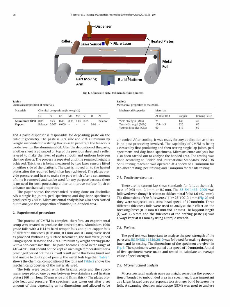
98 J. Butt et al. / Journal of Materials Processing Technology 238 (2016) 96–107
Fig. 1. Composite metal foil manufacturing process.
Table 1Chemical composition of materials.
Materials Chemical composition (in weight%)
Cu Si Fe Mn Mg V O Al
acwoaitaopvoie
Apo
2
sgoauw4pasm
mpva
Table 2Mechanical properties of materials.
Mechanical Properties Materials
Al 1050 H14 Copper Brazing Paste
Yield Strength (MPa) 75 140 45
Aluminium 1050 0.05 0.25 0.40 0.05 0.05 0.05 – BalanceCopper Balance 0.007 0.009 – – – 0.01 –nd a paste dispenser is responsible for depositing paste on theut-out geometry. The paste is 80% zinc and 20% aluminium byeight suspended in a strong flux so as to penetrate the tenacious
xide layer on the aluminium foil. After the deposition of the paste,nother sheet is advanced on top of the previous sheet and a rollers used to make the layer of paste smooth and uniform betweenhe two sheets. The process is repeated until the required height ischieved. Thickness is being measured by two laser sensors fittedn either side of the platform. The part is moved on to the heatedlates after the required height has been achieved. The plates pro-ide pressure and heat to make the part which after a set amountf time is removed and can be used for any purpose because there
s no need for post-processing either to improve surface finish ornhance mechanical properties.
The paper shows the mechanical testing done on dissimilarl/Cu single lap joints, peel specimens and dog-bone specimensroduced by CMFM. Microstructural analysis has also been carriedut to analyse the proportion of bonded/un-bonded area.
. Experimental procedure
The process of CMFM is complex, therefore, an experimentaletup was created to produce the desired parts. Aluminium 1050rade foils with a H14 ½ hard temper foils and pure copper foilsf different thickness (0.05 mm, 0.1 mm and 0.2 mm) were useds provided without any surface treatment. The foils were joinedsing a special 80% zinc and 20% aluminium by weight brazing pasteith a non-corrosive flux. The paste becomes liquid in the range of
10–470 ◦C but should not be kept at such high temperatures for arolonged period of time as it will result in the flux being burnt outnd unable to do its job of joining the metal foils together. Table 1hows the chemical composition of the foils and Table 2 shows theechanical properties of the materials used.
The foils were coated with the brazing paste and the speci-
ens were placed one by one between two stainless steel heatinglates (160 mm long, 35 mm wide and 8 mm thick). The plates pro-ide heat and pressure. The specimen was taken out after a setmount of time depending on its dimensions and allowed to be
Tensile Strength (MPa) 105–145 220 60Young’s Modulus (GPa) 69 117 60
air cooled. After cooling, it was ready for any application as thereis no post-processing involved. The capability of CMFM is beingassessed by first producing and then testing single lap joints, peelspecimens and dog-bone specimens. Microstructure analysis hasalso been carried out to analyse the bonded area. The testing wasdone according to British and International Standards. INSTRON5582 testing machine was operated at a speed of 10 mm/min forlap-shear testing, peel testing and 5 mm/min for tensile testing.
2.1. Tensile lap-shear test
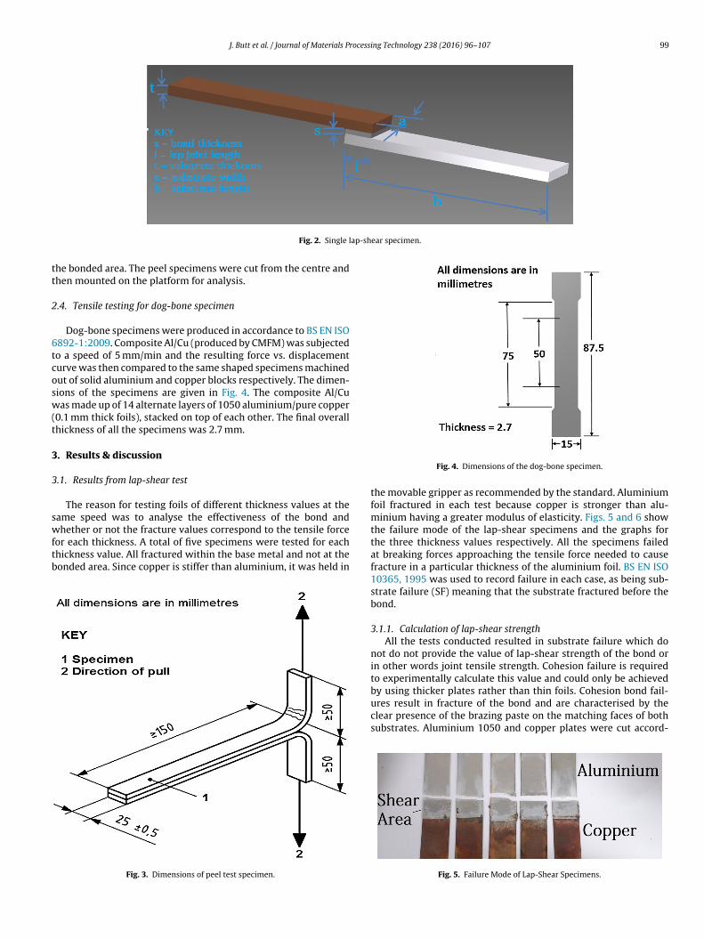
There are no current lap-shear standards for foils at the thick-ness of 0.05 mm, 0.1 mm or 0.2 mm. The BS EN 1465: 2009 wasfollowed even though it relates to thicker metal foils (1.6 ± 0.1 mm).The dimensions of the foils were a*b*t = 25*100*0.1 mm (Fig. 2) andthey were subjected to a cross-head speed of 10 mm/min. Threedifferent thickness foils were used to analyse their effect on thebreaking forces (0.05 mm, 0.1 mm and 0.2 mm). The lap joint length(l) was 12.5 mm and the thickness of the brazing paste (s) wasalways kept at 0.1 mm by using a torque wrench.
2.2. Peel test
The peel test was important to analyse the peel strength of theparts and BS EN ISO 11339:2010 was followed for making the spec-imen and its testing. The dimensions of the specimen are given inFig. 3. The specimens were pulled at a speed of 10 mm/min. A totalof five specimens were made and tested to calculate an averagevalue of peel strength.
2.3. Microstructural analysis
Microstructural analysis gave an insight regarding the propor-tion of bonded to unbounded area in a specimen. It was importantas a larger brazed area corresponds to a stronger bond between thefoils. A scanning electron microscope (SEM) was used to analyse
J. Butt et al. / Journal of Materials Processing Technology 238 (2016) 96–107 99
ap-shear specimen.
tt
2
6tcosw(t
3
3
swftb
Fig. 2. Single l
he bonded area. The peel specimens were cut from the centre andhen mounted on the platform for analysis.
.4. Tensile testing for dog-bone specimen
Dog-bone specimens were produced in accordance to BS EN ISO892-1:2009. Composite Al/Cu (produced by CMFM) was subjectedo a speed of 5 mm/min and the resulting force vs. displacementurve was then compared to the same shaped specimens machinedut of solid aluminium and copper blocks respectively. The dimen-ions of the specimens are given in Fig. 4. The composite Al/Cuas made up of 14 alternate layers of 1050 aluminium/pure copper
0.1 mm thick foils), stacked on top of each other. The final overallhickness of all the specimens was 2.7 mm.
. Results & discussion
.1. Results from lap-shear test
The reason for testing foils of different thickness values at theame speed was to analyse the effectiveness of the bond and
hether or not the fracture values correspond to the tensile forceor each thickness. A total of five specimens were tested for eachhickness value. All fractured within the base metal and not at theonded area. Since copper is stiffer than aluminium, it was held in
Fig. 3. Dimensions of peel test specimen.
Fig. 4. Dimensions of the dog-bone specimen.
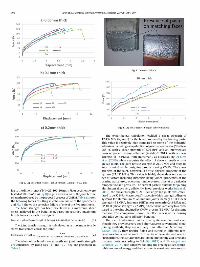
the movable gripper as recommended by the standard. Aluminiumfoil fractured in each test because copper is stronger than alu-minium having a greater modulus of elasticity. Figs. 5 and 6 showthe failure mode of the lap-shear specimens and the graphs forthe three thickness values respectively. All the specimens failedat breaking forces approaching the tensile force needed to causefracture in a particular thickness of the aluminium foil. BS EN ISO10365, 1995 was used to record failure in each case, as being sub-strate failure (SF) meaning that the substrate fractured before thebond.
3.1.1. Calculation of lap-shear strengthAll the tests conducted resulted in substrate failure which do
not do not provide the value of lap-shear strength of the bond orin other words joint tensile strength. Cohesion failure is requiredto experimentally calculate this value and could only be achieved
by using thicker plates rather than thin foils. Cohesion bond fail-ures result in fracture of the bond and are characterised by theclear presence of the brazing paste on the matching faces of bothsubstrates. Aluminium 1050 and copper plates were cut accord-Fig. 5. Failure Mode of Lap-Shear Specimens.
100 J. Butt et al. / Journal of Materials Processing Technology 238 (2016) 96–107
0
50
100
150
200
250
300
0 2 4 6 8 10
Forc
e (N
)
Displacement (mm)
b) 0.1mm thick
S6 S7 S8S9 S10
0
100
200
300
400
500
600
0 2 4 6 8 10 12
Forc
e (N
)
c) 0.2mm thick
S11 S12S13 S14S15
0
20
40
60
80
100
120
140
0 0.5 1 1. 5 2 2. 5 3
Forc
e (N
)
Displacement (mm)
a) 0.05mm thick
S1 S2S3 S4S5
itsta
st
B
s
J
aT
Fig. 7. Cohesion Failure.
0
1000
2000
3000
4000
5000
6000
6543210
Forc
e (N
)
10mm thick
S16 S17S18 S19S20
Displacement (mm)
Fig. 6. Lap shear test results: (a) 0.05 mm; (b) 0.1 mm; (c) 0.2 mm.
ng to the dimensions (a*b*t = 25*100*10 mm). Five specimens wereested at 100 mm/min (Fig. 8) to get a mean value of the joint tensiletrength produced by the proposed process of CMFM. Table 2 showshe breaking forces resulting in cohesion failure of the specimensnd Fig. 7 shows the cohesion failure of one of the five specimens.
The bond strength has been calculated as a maximum sheartress achieved in the bond layer, based on recorded maximumensile forces for each tested joint:
ond strength = Fmax/ (Length of the lap joint ∗ Width of the substrate) (1)
The joint tensile strength is calculated as a maximum tensiletress transferred across the joint:
oint tensile strength = Fmax (2)
(Thickness of the substrate ∗ Width of the substrate)The values of the bond shear strength and joint tensile strengthre calculated by using Eqs. (1) and (2). They are presented inable 3.
Displaceme nt (mm)
Fig. 8. Lap shear test resulting in cohesion failure.
The experimental calculation yielded a shear strength of17.432 MPa (N/mm2) for the bond produced by the brazing paste.This value is relatively high compared to some of the industrialadhesives including a very ductile polyurethane adhesive (Sikaflex-255 FC with a shear strength of 8.26 MPa) and an intermediatetwo-component epoxy adhesive (Araldite® 2015, with a shearstrength of 15.9 MPa, from Huntsman), as discussed by Da Silvaet al. (2009) while analysing the effect of shear strength on sin-gle lap joints. The joint tensile strength is 21.79 MPa and must bekept in mind while designing products using CMFM. The shearstrength of the joint, however, is a true physical property of thesystem (17.432 MPa). This value is highly dependent on a num-ber of factors including materials being joined, properties of thebrazing paste used, operating temperatures, time at a particulartemperature and pressure. The current paste is suitable for joiningaluminium alloys very efficiently. In our previous work (Butt et al.,2016), the shear strength of Al 1050 single lap joints was calcu-lated to be 52 MPa. Masterbond® have a few high strength adhesivesystems for aluminium to aluminium joints, namely EP31 (shearstrength = 31 MPa), Supreme 10HT (shear strength = 24.8 MPa) andEP 30HT (shear strength = 22 MPa). These values are very low com-pared to the value obtained by CMFM process (52 MPa) for the samematerial. This comparison shows the effectiveness of the brazingoperation compared to adhesion bonding.
The use of adhesives has become quite common and eventhough they provide a very good alternative to conventional metaljoining methods, they are not very time effective. According toBaldan (2012), they require fixing and curing at different tem-peratures for a set amount of time to achieve desired results.
Furthermore, the surface preparation before joining add time andmaterial costs. According to Sekulic (2013) and Ebnesajjad andLandrock (2014), both adhesive bonding and brazing utilize compa-rable amount of energy and their economic considerations are also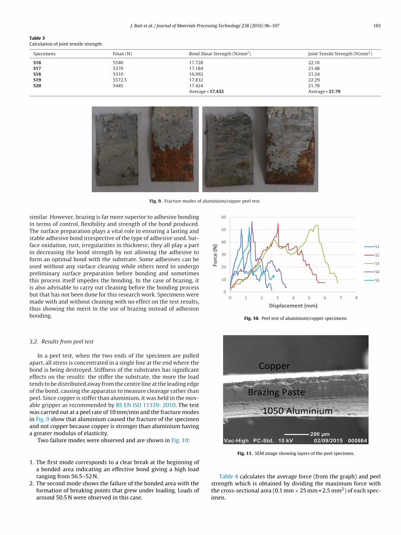
J. Butt et al. / Journal of Materials Processing Technology 238 (2016) 96–107 101
Table 3Calculation of joint tensile strength.
Specimens Fmax (N) Bond Shear Strength (N/mm2) Joint Tensile Strength (N/mm2)
S16 5540 17.728 22.16S17 5370 17.184 21.48S18 5310 16.992 21.24S19 5572.5 17.832 22.29S20 5445 17.424 21.78
Average = 17.432 Average = 21.79
f aluminium/copper peel test.
siTsfifuptibmtb
3
abetopawiaa
1
2
0
10
20
30
40
50
60
0 1 2 3 4 5 6 7 8
Forc
e (N
)
Displaceme nt (mm)
S1
S2
S3
S4
S5
Fig. 10. Peel test of aluminium/copper specimens.
Fig. 9. Fracture modes o
imilar. However, brazing is far more superior to adhesive bondingn terms of control, flexibility and strength of the bond produced.he surface preparation plays a vital role in ensuring a lasting andtable adhesive bond irrespective of the type of adhesive used. Sur-ace oxidation, rust, irregularities in thickness; they all play a partn decreasing the bond strength by not allowing the adhesive toorm an optimal bond with the substrate. Some adhesives can besed without any surface cleaning while others need to undergoreliminary surface preparation before bonding and sometimeshis process itself impedes the bonding. In the case of brazing, its also advisable to carry out cleaning before the bonding processut that has not been done for this research work. Specimens wereade with and without cleaning with no effect on the test results,
hus showing the merit in the use of brazing instead of adhesiononding.
.2. Results from peel test
In a peel test, when the two ends of the specimen are pulledpart, all stress is concentrated in a single line at the end where theond is being destroyed. Stiffness of the substrates has significantffects on the results: the stiffer the substrate, the more the loadends to be distributed away from the centre line at the leading edgef the bond, causing the apparatus to measure cleavage rather thaneel. Since copper is stiffer than aluminium, it was held in the mov-ble gripper as recommended by BS EN ISO 11339: 2010. The testas carried out at a peel rate of 10 mm/min and the fracture modes
n Fig. 9 show that aluminium caused the fracture of the specimennd not copper because copper is stronger than aluminium having
greater modulus of elasticity.Two failure modes were observed and are shown in Fig. 10:
. The first mode corresponds to a clear break at the beginning ofa bonded area indicating an effective bond giving a high load
ranging from 56.5–52 N.. The second mode shows the failure of the bonded area with theformation of breaking points that grew under loading. Loads ofaround 50.5 N were observed in this case.
Fig. 11. SEM image showing layers of the peel specimen.
Table 4 calculates the average force (from the graph) and peelstrength which is obtained by dividing the maximum force with
the cross-sectional area (0.1 mm × 25 mm = 2.5 mm2) of each spec-imen.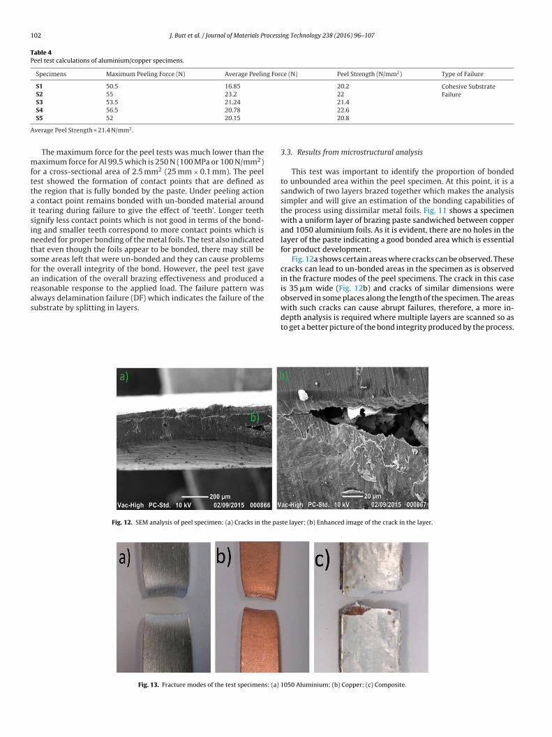
102 J. Butt et al. / Journal of Materials Processing Technology 238 (2016) 96–107
Table 4Peel test calculations of aluminium/copper specimens.
Specimens Maximum Peeling Force (N) Average Peeling Force (N) Peel Strength (N/mm2) Type of Failure
S1 50.5 16.85 20.2 Cohesive SubstrateFailureS2 55 23.2 22
S3 53.5 21.24 21.4S4 56.5 20.78 22.6
A
mfttaisintsfaras
S5 52 20.15
verage Peel Strength = 21.4 N/mm2.
The maximum force for the peel tests was much lower than theaximum force for Al 99.5 which is 250 N (100 MPa or 100 N/mm2)
or a cross-sectional area of 2.5 mm2 (25 mm × 0.1 mm). The peelest showed the formation of contact points that are defined ashe region that is fully bonded by the paste. Under peeling action
contact point remains bonded with un-bonded material aroundt tearing during failure to give the effect of ‘teeth’. Longer teethignify less contact points which is not good in terms of the bond-ng and smaller teeth correspond to more contact points which iseeded for proper bonding of the metal foils. The test also indicatedhat even though the foils appear to be bonded, there may still beome areas left that were un-bonded and they can cause problemsor the overall integrity of the bond. However, the peel test gaven indication of the overall brazing effectiveness and produced aeasonable response to the applied load. The failure pattern waslways delamination failure (DF) which indicates the failure of theubstrate by splitting in layers.
Fig. 12. SEM analysis of peel specimen: (a) Cracks in the pas
Fig. 13. Fracture modes of the test specimens: (a)
20.8
3.3. Results from microstructural analysis
This test was important to identify the proportion of bondedto unbounded area within the peel specimen. At this point, it is asandwich of two layers brazed together which makes the analysissimpler and will give an estimation of the bonding capabilities ofthe process using dissimilar metal foils. Fig. 11 shows a specimenwith a uniform layer of brazing paste sandwiched between copperand 1050 aluminium foils. As it is evident, there are no holes in thelayer of the paste indicating a good bonded area which is essentialfor product development.
Fig. 12a shows certain areas where cracks can be observed. Thesecracks can lead to un-bonded areas in the specimen as is observedin the fracture modes of the peel specimens. The crack in this caseis 35 �m wide (Fig. 12b) and cracks of similar dimensions wereobserved in some places along the length of the specimen. The areaswith such cracks can cause abrupt failures, therefore, a more in-
depth analysis is required where multiple layers are scanned so asto get a better picture of the bond integrity produced by the process.te layer; (b) Enhanced image of the crack in the layer.
1050 Aluminium; (b) Copper; (c) Composite.
J. Butt et al. / Journal of Materials Processing Technology 238 (2016) 96–107 103
0
1
2
3
4
5
6
7
8
9
10
0 5 10 15 20
Forc
e (k
N)
Displacement (mm)
Composite
Alu minium 1050
Copper
3
patcustsei
efcbpisiasictsdfptifctytacraic
at
0
1
2
3
4
5
6
7
8
9
0 5 10 15 20
Forc
e (k
N)
Composite
Alu minium 1050
Copper
joining similar as well as dissimilar metals but its application for
Fig. 14. Comparative Tensile Test.
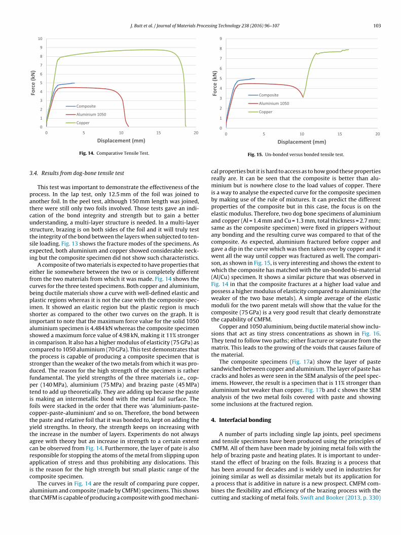
.4. Results from dog-bone tensile test
This test was important to demonstrate the effectiveness of therocess. In the lap test, only 12.5 mm of the foil was joined tonother foil. In the peel test, although 150 mm length was joined,here were still only two foils involved. Those tests gave an indi-ation of the bond integrity and strength but to gain a betternderstanding, a multi-layer structure is needed. In a multi-layertructure, brazing is on both sides of the foil and it will truly testhe integrity of the bond between the layers when subjected to ten-ile loading. Fig. 13 shows the fracture modes of the specimens. Asxpected, both aluminium and copper showed considerable neck-ng but the composite specimen did not show such characteristics.
A composite of two materials is expected to have properties thatither lie somewhere between the two or is completely differentrom the two materials from which it was made. Fig. 14 shows theurves for the three tested specimens. Both copper and aluminium,eing ductile materials show a curve with well-defined elastic andlastic regions whereas it is not the case with the composite spec-
men. It showed an elastic region but the plastic region is muchhorter as compared to the other two curves on the graph. It ismportant to note that the maximum force value for the solid 1050luminium specimen is 4.484 kN whereas the composite specimenhowed a maximum force value of 4.98 kN, making it 11% strongern comparison. It also has a higher modulus of elasticity (75 GPa) asompared to 1050 aluminium (70 GPa). This test demonstrates thathe process is capable of producing a composite specimen that istronger than the weaker of the two metals from which it was pro-uced. The reason for the high strength of the specimen is rather
undamental. The yield strengths of the three materials i.e., cop-er (140 MPa), aluminium (75 MPa) and brazing paste (45 MPa)end to add up theoretically. They are adding up because the pastes making an intermetallic bond with the metal foil surface. Theoils were stacked in the order that there was ‘aluminium-paste-opper-paste-aluminium’ and so on. Therefore, the bond betweenhe paste and relative foil that it was bonded to, kept on adding theield strengths. In theory, the strength keeps on increasing withhe increase in the number of layers. Experiments do not alwaysgree with theory but an increase in strength to a certain extentan be observed from Fig. 14. Furthermore, the layer of pate is alsoesponsible for stopping the atoms of the metal from slipping uponpplication of stress and thus prohibiting any dislocations. Thiss the reason for the high strength but small plastic range of theomposite specimen.
The curves in Fig. 14 are the result of comparing pure copper,luminium and composite (made by CMFM) specimens. This showshat CMFM is capable of producing a composite with good mechani-
Displaceme nt (mm)
Fig. 15. Un-bonded versus bonded tensile test.
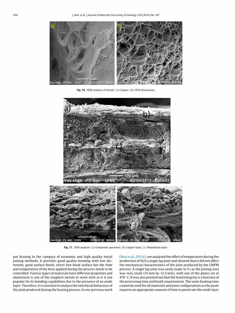
cal properties but it is hard to access as to how good these propertiesreally are. It can be seen that the composite is better than alu-minium but is nowhere close to the load values of copper. Thereis a way to analyse the expected curve for the composite specimenby making use of the rule of mixtures. It can predict the differentproperties of the composite but in this case, the focus is on theelastic modulus. Therefore, two dog bone specimens of aluminiumand copper (Al = 1.4 mm and Cu = 1.3 mm, total thickness = 2.7 mm;same as the composite specimen) were fixed in grippers withoutany bonding and the resulting curve was compared to that of thecomposite. As expected, aluminium fractured before copper andgave a dip in the curve which was then taken over by copper and itwent all the way until copper was fractured as well. The compari-son, as shown in Fig. 15, is very interesting and shows the extent towhich the composite has matched with the un-bonded bi-material(Al/Cu) specimen. It shows a similar picture that was observed inFig. 14 in that the composite fractures at a higher load value andpossess a higher modulus of elasticity compared to aluminium (theweaker of the two base metals). A simple average of the elasticmoduli for the two parent metals will show that the value for thecomposite (75 GPa) is a very good result that clearly demonstratethe capability of CMFM.
Copper and 1050 aluminium, being ductile material show inclu-sions that act as tiny stress concentrations as shown in Fig. 16.They tend to follow two paths; either fracture or separate from thematrix. This leads to the growing of the voids that causes failure ofthe material.
The composite specimens (Fig. 17a) show the layer of pastesandwiched between copper and aluminium. The layer of paste hascracks and holes as were seen in the SEM analysis of the peel spec-imens. However, the result is a specimen that is 11% stronger thanaluminium but weaker than copper. Fig. 17b and c shows the SEManalysis of the two metal foils covered with paste and showingsome inclusions at the fractured region.
4. Interfacial bonding
A number of parts including single lap joints, peel specimensand tensile specimens have been produced using the principles ofCMFM. All of them have been made by joining metal foils with thehelp of brazing paste and heating plates. It is important to under-stand the effect of brazing on the foils. Brazing is a process thathas been around for decades and is widely used in industries for
a process that is additive in nature is a new prospect. CMFM com-bines the flexibility and efficiency of the brazing process with thecutting and stacking of metal foils. Swift and Booker (2013, p. 330)
104 J. Butt et al. / Journal of Materials Processing Technology 238 (2016) 96–107
Fig. 16. SEM analysis of metals: (a) Copper; (b) 1050 Aluminium.
cimen
pjtacaplt
Fig. 17. SEM analysis: (a) Composite spe
ut brazing in the category of economic and high quality metaloining methods. It provides good quality bonding with low dis-ortion, good surface finish, stress free bond surface but the timend temperature of the heat applied during the process needs to beontrolled. Various types of materials have different properties and
luminium is one of the toughest metals to work with as it is notopular for its bonding capabilities due to the presence of an oxideayer. Therefore, it is essential to analyse the interfacial behaviour ofhe joint produced during the brazing process. In our previous work
; (b) Copper layer; (c) Aluminium layer.
(Butt et al., 2015c), we analysed the effect of temperature during theproduction of Al/Cu single lap joint and showed that it did not affectthe mechanical characteristics of the joint produced by the CMFMprocess. A single lap joint was easily made in 5 s as the joining areawas very small (25 mm by 12.5 mm), with one of the plates set at
470 ◦C. It was also pointed out that the bond integrity is a function ofthe processing time and build requirements. The same heating timecannot be used for all materials and joint configurations as the pasterequires an appropriate amount of time to penetrate the oxide layer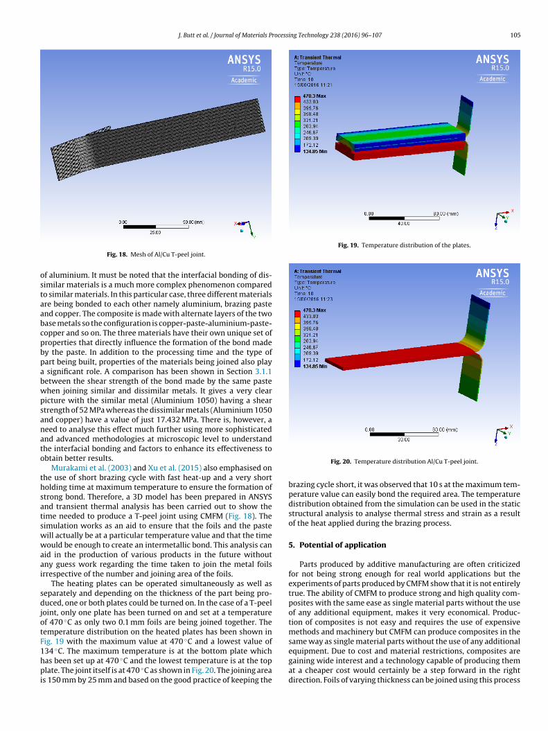
J. Butt et al. / Journal of Materials Processing Technology 238 (2016) 96–107 105
ostaabcpbpabwpsanato
thsatswwaai
sdjotF1hpi
Fig. 19. Temperature distribution of the plates.
Fig. 18. Mesh of Al/Cu T-peel joint.
f aluminium. It must be noted that the interfacial bonding of dis-imilar materials is a much more complex phenomenon comparedo similar materials. In this particular case, three different materialsre being bonded to each other namely aluminium, brazing pastend copper. The composite is made with alternate layers of the twoase metals so the configuration is copper-paste-aluminium-paste-opper and so on. The three materials have their own unique set ofroperties that directly influence the formation of the bond madey the paste. In addition to the processing time and the type ofart being built, properties of the materials being joined also play
significant role. A comparison has been shown in Section 3.1.1etween the shear strength of the bond made by the same pastehen joining similar and dissimilar metals. It gives a very clear
icture with the similar metal (Aluminium 1050) having a sheartrength of 52 MPa whereas the dissimilar metals (Aluminium 1050nd copper) have a value of just 17.432 MPa. There is, however, aeed to analyse this effect much further using more sophisticatednd advanced methodologies at microscopic level to understandhe interfacial bonding and factors to enhance its effectiveness tobtain better results.
Murakami et al. (2003) and Xu et al. (2015) also emphasised onhe use of short brazing cycle with fast heat-up and a very shortolding time at maximum temperature to ensure the formation oftrong bond. Therefore, a 3D model has been prepared in ANSYSnd transient thermal analysis has been carried out to show theime needed to produce a T-peel joint using CMFM (Fig. 18). Theimulation works as an aid to ensure that the foils and the pasteill actually be at a particular temperature value and that the timeould be enough to create an intermetallic bond. This analysis can
id in the production of various products in the future withoutny guess work regarding the time taken to join the metal foilsrrespective of the number and joining area of the foils.
The heating plates can be operated simultaneously as well aseparately and depending on the thickness of the part being pro-uced, one or both plates could be turned on. In the case of a T-peel
oint, only one plate has been turned on and set at a temperaturef 470 ◦C as only two 0.1 mm foils are being joined together. Theemperature distribution on the heated plates has been shown inig. 19 with the maximum value at 470 ◦C and a lowest value of
34 ◦C. The maximum temperature is at the bottom plate whichas been set up at 470 ◦C and the lowest temperature is at the toplate. The joint itself is at 470 ◦C as shown in Fig. 20. The joining areas 150 mm by 25 mm and based on the good practice of keeping the
Fig. 20. Temperature distribution Al/Cu T-peel joint.
brazing cycle short, it was observed that 10 s at the maximum tem-perature value can easily bond the required area. The temperaturedistribution obtained from the simulation can be used in the staticstructural analysis to analyse thermal stress and strain as a resultof the heat applied during the brazing process.
5. Potential of application
Parts produced by additive manufacturing are often criticizedfor not being strong enough for real world applications but theexperiments of parts produced by CMFM show that it is not entirelytrue. The ability of CMFM to produce strong and high quality com-posites with the same ease as single material parts without the useof any additional equipment, makes it very economical. Produc-tion of composites is not easy and requires the use of expensivemethods and machinery but CMFM can produce composites in thesame way as single material parts without the use of any additional
equipment. Due to cost and material restrictions, composites aregaining wide interest and a technology capable of producing themat a cheaper cost would certainly be a step forward in the rightdirection. Foils of varying thickness can be joined using this process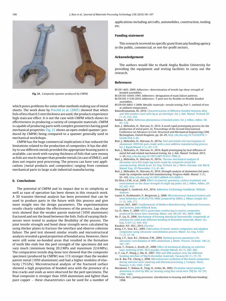
106 J. Butt et al. / Journal of Materials Process
wsfheimdm
liaadcm
6
wAumrtfnjufawovTsptsffip
Murakami, T., Nakata, K., Tong, H., Ushio, M., 2003. Dissimilar metal joining of
Fig. 21. Composite spanner produced by CMFM.
hich poses problems for some other methods making use of metalheets. The work done by Prechtl et al. (2005) showed that whenoils of less than 0.5 mm thickness are used, the products experienceigh staircase effect. It is not the case with CMFM which shows itsffectiveness in producing a variety of composite materials. CMFMs capable of producing parts with complex geometries having good
echanical properties. Fig. 21 shows an open-ended spanner (pro-uced by CMFM) being compared to a spanner generally used inechanical workshops.
CMFM has the huge commercial implications it has reduced theimitations related to the production of composites. It has the abil-ty to use different metals provided the appropriate brazing paste isvailable, can work with varying thickness of foils that save moneys foils are much cheaper than powder metals (in case of DMLS), andoes not require post processing. The process can have vast appli-ations (metal products and composites) ranging from commonechanical parts to large scale industrial manufacturing.
. Conclusions
The potential of CMFM and its impact due to its simplicity asell as ease of operation has been shown in this research work.
3D transien thermal analysis has been presented that can besed to produce parts in the future with this process and giveore insight into the design parameters. The experimentation
esults clearly validate the effectiveness of the process. Lap-shearests showed that the weaker parent material (1050 aluminium)ractured and not the bond between the foils. Foils of varying thick-esses were tested to analyse the flexibility of the process. The
oint tensile strength and bond shear strength were calculated bysing thicker plates to fracture the interface and observe cohesion
ailure. The peel test showed similar results and microstructuralnalysis revealed a good proportion of bonded area. However, thereere still some no-bonded areas that resulted in the formation
f teeth like ends but the peel strength of the specimens did notary much (minimum being 20.2 MPa and maximum 22.6 MPa).he comparative tensile dog-bone test showed that the compositepecimen (produced by CMFM) was 11% stronger than the weakerarent metal (1050 aluminium) and had a higher modulus of elas-icity (75 GPa). Microstructural analysis of the fractured surfacehowed a high proportion of bonded area with the presence of a
ew cracks and voids as were observed for the peel specimens. Thenal composite is stronger than 1050 aluminium and lighter thanure copper − these characteristics can be used for a number ofing Technology 238 (2016) 96–107
applications including aircrafts, automobiles, construction, toolingetc.
Funding statement
This research received no specific grant from any funding agencyin the public, commercial, or not-for-profit sectors.
Acknowledgement
The authors would like to thank Anglia Ruskin University forproviding the equipment and testing facilities to carry out theresearch.
References
BS EN 1465: 2009. Adhesives—determination of tensile lap-shear strength ofbonded assemblies.
BS EN ISO 10365:1995. Adhesives—designation of main failure patterns.BS EN ISO 11339:2010, Adhesives—T-peel test for flexible-to-flexible bonded
assemblies.BS EN ISO 6892-1:2009, Metallic materials—tensile testing, Part 1: method of test
at ambient temperature.Balasubramanian, M., 2016. Characterization of diffusion-bonded titanium alloy
and 304 stainless steel with Ag as an interlayer. Int. J. Adv. Manuf. Technol. 82(1–4), 153–162.
Baldan, A., 2012. Adhesion phenomena in bonded joints. Int. J. Adhes. Adhes. 38,95–116.
Butt, J., Mebrahtu, H., Shirvani, H., 2014. A novel rapid prototyping process for theproduction of metal parts. In: Proceedings of the Second InternationalConference on Advances in Civil, Structural and Mechanical Engineering-CSM,Birmingham, United Kingdom, pp. 26–29, http://dx.doi.org/10.15224/978-1-63248-054-5-45.
Butt, J., Mebrahtu, H., Shirvani, H., 2015a. Peel and tensile test investigation ofaluminium 1050 foil parts made with a new additive manufacturing process.Int. J. Rapid Manuf. 5 (1), 95–115.
Butt, J., Mebrahtu, H., Shirvani, H., 2016. Rapid prototyping by heat diffusion ofmetal foil and related mechanical testing. Int. J. Adv. Manuf. Technol. 2015,1–10, http://dx.doi.org/10.1007/s00170-015-7882-8.
Butt, J., Mebrahtu, H., Shirvani, H., 2015c. Thermo-mechanical analysis ofdissimilar al/cu foil single lap joints made by composite metal foilmanufacturing. World Acad. Sci. Eng. Technol. Int. J. Mech. Aerospa. Ind. Mech.Manuf. Eng. 10 (November (1)), 41–46.
Butt, J., Mebrahtu, H., Shirvani, H., 2016. Strength analysis of aluminium foil partsmade by composite metal foil manufacturing. Progress Addit. Manuf. 1 (1),93–103, http://dx.doi.org/10.1007/s40964-016-0008-5.
Da Silva, L.F.M., et al., 2009. Effect of material, geometry, surface treatment andenvironment on the shear strength of single lap joints. Int. J. Adhes. Adhes. 29(6), 621–632.
Ebnesajjad, S., Landrock, A.H., 2014. Adhesives Technology Handbook. WilliamAndrew.
Gaard, A., Krakhmalev, P., Bergstrom, J., 2006. Microstructural characterization andwear behaviour of (Fe,Ni)?TiC MMC prepared by DMLS. J. Alloys Compd. 421(1–2), 166–171.
Groover, M.P., 2007. Fundamentals of Modern Manufacturing: Materials Processes,and Systems. John Wiley & Sons.
Gu, D., Shen, Y., 2006. WCCo particulate reinforcing Cu matrix compositesproduced by direct laser sintering. Mater. Lett. 60 (29–30), 3664–3668.
He, P., Liu, D., 2006. Mechanism of forming interfacial intermetallic compounds atinterface for solid state diffusion bonding of dissimilar materials. Mater. Sci.Eng. A 437 (2), 430–435.
Kazakov, N.F. (Ed.), 2013. Elsevier.Kong, C.Y., Soar, R.C., 2005. Fabrication of metal–matrix composites and adaptive
composites using ultrasonic consolidation process. Mater. Sci. Eng. A 412(1–2), 12–18.
Kong, C.Y., Soar, R.C., Dickens, P.M., 2004. Optimal process parameters forultrasonic consolidation of 3003 aluminium. J. Mater. Process. Technol. 146 (2),181–187.
Laoui, T., Froyen, L., Kruth, J.P., 2000. Effect of mechanical alloying on selectivelaser sintering of WC–9CO powder. Powder Metall. 42 (3), 203–205.
Li, Y., Liu, P., Wang, J., Ma, H., 2007. XRD and SEM analysis near the diffusionbonding interface of Mg/Al dissimilar materials. Vacuum 82 (1), 15–19.
Liu, B., Bai, P.K., Cheng, J., 2008. Microstructure evolution of Mo-based compositesduring selective laser sintering and thermal processing. J. Comput. Theor.Nanosci. 5 (8), 1565–1569.
aluminum to steel by MIG arc brazing using flux cored wire. ISIJ Int. 43 (10),1596–1602.
Nicholas, M.G., Joining processes: introduction to brazing and diffusion bonding’,1998.

rocessi
P
P
R
S
S
S
of joint for stirring brazing of dissimilar Al/Mg alloy during heating processes.Rare Met. 34 (4), 245–250.
Zhan, Y., Han, J., Zhang, X., He, X., Li, Z., Du, S., 2001. Rapid prototyping andcombustion synthesis of TiC/Ni functionally gradient materials. Mater. Sci. Eng.A 299, 218–224.
J. Butt et al. / Journal of Materials P
rechtl, M., Pursche, L., Otto, A., 2004. System technology and data preparation forautomated laser assisted stacking of metal foil. In: Proc. of the 4thInternational Conference on Laser Assisted Net Shape Engineering – LANE,Germany, pp. 601–610.
rechtl, M., Otto, A., Geiger, M., 2005. Rapid tooling by laminated objectmanufacturing of metal foil. Trans. Tech. 6–8, 302–312.
ambo, C.R., Travitzky, N., Zimmermann, K., Greil, P., 2005. Synthesis of TiC/Ti?Cucomposites by pressureless reactive infiltration of TiCu alloy into carbonpreforms fabricated by 3D-printing. Mater. Lett. 59, 1028–1031.
ekulic, D.P., 2013. Advances in Brazing: Science, Technology and Applications.Elsevier.
imchi, A., Pohl, H., 2004. Direct laser sintering of iron–graphite powder mixture.Mater. Sci. Eng. A 383 (2), 191–200.
locombe, A., Li, L., 2001. Selective laser sintering of TiC—Al2O3 composite withself propagating high-temperature synthesis. J. Mater. Process. Technol. 118,173–178.
ng Technology 238 (2016) 96–107 107
Swift, K.G., Booker, J.D., 2013. Manufacturing Process Selection Handbook.Butterworth-Heinemann.
Xiong, Y., Smugeresky, J.E., Ajdelsztajn, L., Schoenung, J.M., 2008. Fabrication ofwc-co cermets by laser engineered net shaping. Mater. Sci. Eng. A 493 (1–2),261–266.
Xu, H.B., Sun, H.B., Yang, H., Chi, L.X., Chen, J., 2015. Microstructure and properties


![Homepage [] · 2016-12-11 · Compo on Compos i ± ion Composition Compo si tion Composition Composition Composition Composition ... Cylinder TRIM Steatite TRIM REC TUNING VFO TUNING](https://static.fdocuments.us/doc/165x107/5f99801b70d8f630802d58e4/homepage-2016-12-11-compo-on-compos-i-ion-composition-compo-si-tion-composition.jpg)
![P5 Parents’ Briefingswt3.vatitude.com/qql/slot/u413/[9]_P5_Parents_Briefing_TL_2014[1].… · Assessment includes Writing (Compo) 20% (40) Language use & Comprehension (Paper 2)](https://static.fdocuments.us/doc/165x107/60617a3ccf289410233b297c/p5-parentsa-9p5parentsbriefingtl20141-assessment-includes-writing-compo.jpg)