6 5 CG1 - SMC CorporationNon-lube/Rubber bumper Non-lube/Air cushion Type Electrical entry Grommet...
64
Series Variations Series Standard Series CG1 Standard Series CG1 Non-rotating Rod Series CG1K Direct Mount Series CG1R Direct Mount, Non-rotating Rod Series CG1KR Low Friction Series CG1Q With End Lock Series CBG1 Action Double acting Single acting Double acting Double acting Double acting Double acting Rod Single rod Double rod Single rod (Spring return/ Spring extend) Double rod Single rod Single rod Single rod Single rod Double acting Single rod Cushion Rubber Air Rubber Air Rubber Rubber Air Rubber Rubber Air Rubber Without (ø20 to ø32) Rubber (ø40 to ø100) Air Cylinder Series CG1 ø20, ø25, ø32, ø40, ø50, ø63, ø80, ø100 6-5-46 Basic Standard variations Built-in One-touch fittings With rod boot Air-hydro Clean series Copper- free Bore size (mm) 20 to 100 20 to 40 20 to 63 40 to 63 20 to 63 20 to 63 20 to 63 20 to 100 Page 6-5-2 6-5-16 6-5-22 6-5-30 6-5-35 6-5-40 6-5-49 20 to 100 6-5-55 6-5-1 CJ1 CJP CJ2 CM2 CG1 MB MB1 CA2 CS1 C76 C85 C95 CP95 NCM NCA D- -X 20- Data
Transcript of 6 5 CG1 - SMC CorporationNon-lube/Rubber bumper Non-lube/Air cushion Type Electrical entry Grommet...

Series VariationsSeries
Standard Series CG1
StandardSeries CG1
Non-rotating RodSeries CG1K
Direct MountSeries CG1R
Direct Mount, Non-rotating RodSeries CG1KR
Low FrictionSeries CG1�Q
With End LockSeries CBG1
Action
Doubleacting
Singleacting
Doubleacting
Doubleacting
Doubleacting
Doubleacting
Rod
Single rod
Doublerod
Singlerod
(Springreturn/Springextend)
Doublerod
Singlerod
Singlerod
Singlerod
Singlerod
Doubleacting
Singlerod
Cushion
Rubber
Air
Rubber
Air
Rubber
Rubber
Air
Rubber
Rubber
Air
Rubber
Without(ø20 to
ø32)Rubber(ø40 to ø100)
Air Cylinder
Series CG1ø20, ø25, ø32, ø40, ø50, ø63, ø80, ø100
6-5-46
BasicStandard variations
Built-inOne-touch
fittingsWith
rod boot Air-hydro Cleanseries
Copper-free
Bore size(mm)
20to
100
20to40
20to63
40to63
20to63
20to63
20to63
20to
100
Page
6-5-2
6-5-16
6-5-22
6-5-30
6-5-35
6-5-40
6-5-49
20to
1006-5-55
6-5-1
CJ1
CJP
CJ2
CM2
CG1
MB
MB1
CA2
CS1
C76
C85
C95
CP95
NCM
NCA
D-
-X
20-
Data

CDG1With auto switch
L 25
L
N
N 25 H7BW
Built-in magnet
20253240
506380
100
Bore size20 mm25 mm32 mm40 mm
50 mm63 mm80 mm
100 mm
NilSn
2 pcs.1 pc.
“n” pcs.
NilWithout auto switch
(Built-in magnet)
Auto switch
Cylinder stroke (mm)
CG1
Basic styleAxial foot style
Rod side flange styleHead side flange styleRod side trunnion styleHead side trunnion style
Clevis style
Mounting styleBLFGUTD
100
100
NilJK
Suffix for cylinder (Rod boot (at one end))
Without rod bootNylon tarpaulin
Heat resistant tarpaulin
TypeNA
Non-lube/Rubber bumperNon-lube/Air cushion
Type Electricalentry
Grommet
Grommet
Grommet
Grommet
Indi
cato
r lig
ht
Wiring (Output)
2-wire
3-wire(NPN equivalent)
Load voltage
—
ACDC
Auto switch model
C76
B54C73
C73C
B59W
H7A1H7A2H7BH7C
H7NWH7PWH7BW
H7BA
H7NF
Lead wire length (m) ∗
0.5(Nil)
3(L)
5(Z)
�
�
�
�
�
�
�
�
�
�
�
�
�
�
�
�
�
�
�
�
�
�
�
�
�
�
�
—
�
�
�
—
�
�
�
�
�
�
�
�
�
ICcircuit
Relay, PLC
Applicable load
Applicable Auto Switch/Refer to page 6-16-1 for further information on auto switches.
∗ Lead wire length symbols: 0.5 m ·········· Nil (Example) C73C 3 m·········· L (Example) C73CL5 m·········· Z (Example) C73CZ
None ·········· N (Example) C73CN
• Since there are other applicable auto switches than listed, refer to page 6-5-14 for details.• For details about auto switches with pre-wire connector, refer to page 6-16-60.
20 to 63
—
——
G59G5PK59—
G59WG5PWK59W
G5BA
G59F
80, 100
—
5 V
100 V, 200 V
100 V
—
12 V
—
5 V, 12 V
12 V
5 V, 12 V
12 V
5 V, 12 V
—
—
24 VConnector
Connector
Special function
Diagnostic indication(2-color indication)
With diagnostic output(2-color indication)
Water resistant (2-color indication)
Diagnostic indication(2-color indication)
—
—
Yes
Yes
2-wire
3-wire (NPN) 3-wire (PNP)
2-wire
3-wire (NPN) 3-wire (PNP)
4-wire (NPN)
24 V
ICcircuit
—
ICcircuit
—
ICcircuit
Relay, PLC
Applicable bore size (mm)
Ree
d sw
itch
Sol
id s
tate
sw
itch
None(N)
Pre-wireconnector
—
——�
—
———�
———
—
—
—
———
—
�
�
�
—�
�
�
�
�
∗ Solid state switches marked with “�” are produced upon receipt of order.
—
How to Order
∗ In the case of w/ rod boot, and a foot bracket or rod side flange as a bracket, those parts are to be assembled at the time of shipment.
Refer to “Standard Stroke” on page 6-5-3.
∗ For the applicable auto switch model, refer to the table be-low.
∗
∗
∗ Not available for ø80 or ø100.
Note) Mounting brackets are shipped together, (but not assembled).
Number ofauto switches
Air Cylinder: Standard TypeDouble Acting, Single Rod
Series CG1ø20, ø25, ø32, ø40, ø50, ø63, ø80, ø100
Withoutauto switch
6-5-2
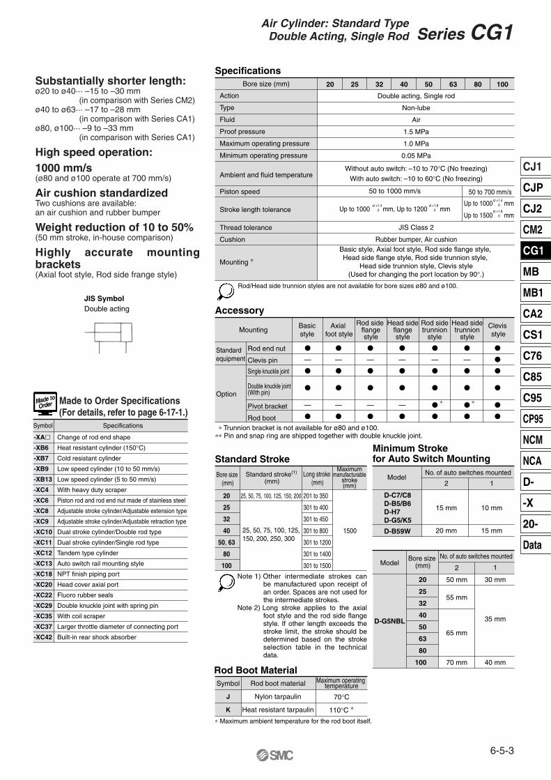
50 to 1000 mm/s
Up to 1000 mm, Up to 1200 mm
Rod/Head side trunnion styles are not available for bore sizes ø80 and ø100.
Specifications
Action
Type
Fluid
Proof pressure
Maximum operating pressure
Minimum operating pressure
Ambient and fluid temperature
Piston speed
Stroke length tolerance
Thread tolerance
Cushion
Mounting ∗
Double acting, Single rod
Non-lube
Air
1.5 MPa
1.0 MPa
0.05 MPa
Without auto switch: –10 to 70°C (No freezing)
With auto switch: –10 to 60°C (No freezing)
Basic style, Axial foot style, Rod side flange style, Head side flange style, Rod side trunnion style,
Head side trunnion style, Clevis style(Used for changing the port location by 90°.)
∗ Trunnion bracket is not available for ø80 and ø100.∗∗ Pin and snap ring are shipped together with double knuckle joint.
Accessory
Mounting
Standard equipment
Option
Rod end nut
Clevis pin
Single knuckle joint
Double knuckle joint(With pin)
Pivot bracket
Rod boot
Basicstyle
Axial foot style
Rod side flangestyle
Head sideflangestyle
Rod sidetrunnion
style
Head sidetrunnion
style
Clevis style
Standard Stroke
Bore size (mm)
20
25
32
40
50, 63
80
100
Standard stroke(1)
(mm)
25, 50, 75, 100, 125, 150, 200
25, 50, 75, 100, 125, 150, 200, 250, 300
Long stroke (mm)
Maximummanufacturable
stroke(mm)
201 to 350
301 to 400
301 to 450
301 to 800
301 to 1200
301 to 1400
301 to 1500
1500
∗ Maximum ambient temperature for the rod boot itself.
Rod Boot MaterialSymbol
J
K
Rod boot material
Nylon tarpaulin
Heat resistant tarpaulin
Maximum operating temperature
70°C
110°C ∗
Minimum Stroke for Auto Switch Mounting
Model2
15 mm
20 mm
1
10 mm
15 mm
D-C7/C8D-B5/B6D-H7D-G5/K5
D-B59W
No. of auto switches mounted
∗∗
20 25 32 40 50 63 80 100
50 to 700 mm/s
Up to 1000 mm
Up to 1500 mm
D-G5NBL
ModelBore size
(mm)
20
25
32
40
50
63
80
100
30 mm50 mm
55 mm
35 mm
65 mm
40 mm70 mm
2 1
No. of auto switches mounted
Substantially shorter length:ø20 to ø40··· –15 to –30 mm
(in comparison with Series CM2)ø40 to ø63··· –17 to –28 mm
(in comparison with Series CA1)ø80, ø100··· –9 to –33 mm
(in comparison with Series CA1)
High speed operation:1000 mm/s(ø80 and ø100 operate at 700 mm/s)
Air cushion standardizedTwo cushions are available: an air cushion and rubber bumper
Weight reduction of 10 to 50%(50 mm stroke, in-house comparison)
Highly accurate mounting brackets(Axial foot style, Rod side frange style)
-XA�
-XB6
-XB7
-XB9
-XB13
-XC4
-XC6
-XC8
-XC9
-XC10
-XC11
-XC12
-XC13
-XC18
-XC20
-XC22
-XC29
-XC35
-XC37
-XC42
Change of rod end shape
Heat resistant cylinder (150°C)
Cold resistant cylinder
Low speed cylinder (10 to 50 mm/s)
Low speed cylinder (5 to 50 mm/s)
With heavy duty scraper
Piston rod and rod end nut made of stainless steel
Adjustable stroke cylinder/Adjustable extension type
Adjustable stroke cylinder/Adjustable retraction type
Dual stroke cylinder/Double rod type
Dual stroke cylinder/Single rod type
Tandem type cylinder
Auto switch rail mounting style
NPT finish piping port
Head cover axial port
Fluoro rubber seals
Double knuckle joint with spring pin
With coil scraper
Larger throttle diameter of connecting port
Built-in rear shock absorber
Symbol Specifications
Made to Order Specifications(For details, refer to page 6-17-1.)
JIS Class 2
Rubber bumper, Air cushion
�
—
�
�
—
�
�
—
�
�
—
�
�
—
�
�
—
�
�
—
�
�
—
�
�
—
�
�
�
�
�
—
�
�
�
�
�
�
�
�
�
�
Note 1) Other intermediate strokes can be manufactured upon receipt of an order. Spaces are not used for the intermediate strokes.
Note 2) Long stroke applies to the axial foot style and the rod side flange style. If other length exceeds the stroke limit, the stroke should be determined based on the stroke selection table in the technical data.
st +1.80
st +1.80
st +1.40
st +1.40
Bore size (mm)
JIS SymbolDouble acting
6-5-3
Series CG1Air Cylinder: Standard TypeDouble Acting, Single Rod
CJ1
CJP
CJ2
CM2
CG1
MB
MB1
CA2
CS1
C76
C85
C95
CP95
NCM
NCA
D-
-X
20-
Data

ø20 to ø63
ø20 to ø63
ø80, ø100
Note 1) Order two foot brackets per cylinder. Note 2) Clevis pin, snap ring and mounting bolt are shipped together with clevis style. Note 3) Mounting bolts are shipped together for foot style and flange style.
Mounting Bracket Part No.
Axial foot (1)
Flange
Trunnion pin
Cleveis (2)
Pivot bracket
Mounting bracketBore size (mm)
20
CG-L020
CG-F020
CG-T020
CG-D020
CG-020-24A
25
CG-L025
CG-F025
CG-T025
CG-D025
CG-025-24A
32
CG-L032
CG-F032
CG-T032
CG-D032
CG-032-24A
40
CG-L040
CG-F040
CG-T040
CG-D040
CG-040-24A
50
CG-L050
CG-F050
CG-T050
CG-D050
CG-050-24A
63
CG-L063
CG-F063
CG-T063
CG-D063
CG-063-24A
80
CG-L080
CG-F080
—
CG-D080
CG-080-24A
100
CG-L100
CG-F100
—
CG-D100
CG-100-24A
Auto Switch Mounting Bracket Part No.Auto switch
model
D-C7/C8
D-H7
D-B5/B6
D-G5/K5
Bore size (mm)
20
BMA2-020
BA-01
25
BMA2-025
BA-02
32
BMA2-032
BA-32
40
BMA2-040
BA-04
50
BMA2-050
BA-05
63
BMA2-063
BA-06
80
—
BA-08
100
—
BA-10
Weight (kg)
Bore size (mm)
Bas
ic w
eigh
t
Basic style
Axial foot style
Flange style
Trunnion style
Clevis style
Pivot bracket
Single knuckle joint
Double knuckle joint (With pin)
20
0.10
0.21
0.18
0.11
0.15
0.08
0.05
0.05
0.05
0.01
0.01
25
0.17
0.30
0.27
0.19
0.25
0.09
0.09
0.09
0.07
0.01
0.01
32
0.26
0.42
0.40
0.29
0.41
0.17
0.09
0.09
0.09
0.02
0.02
40
0.41
0.63
0.61
0.46
0.64
0.25
0.10
0.13
0.15
0.02
0.03
50
0.77
1.25
1.11
0.91
1.17
0.44
0.22
0.26
0.22
0.03
0.06
63
1.07
1.79
1.57
1.21
1.75
0.80
0.22
0.26
0.26
0.03
0.10
80
2.04
3.00
2.75
—
2.75
0.98
0.39
0.64
0.35
0.03
0.19
100
3.17
4.92
4.52
—
4.45
1.75
0.57
1.31
0.49
0.03
0.26
Mounting procedure for trunnionFollow the procedures below when mounting a pivot bracket on the trunnion.
Mounting procedure for clevisFollow the procedures below when mounting a pivot bracket on the clevis style.
Calculation: (Example) CG1LA20-100(Foot style, ø20, 100 st)
• Basic weight·················0.21 (Foot, ø20)• Additional weight··········0.05/50 stroke• Cylinder stroke············· 100 stroke• Additional weight by air cushion··········0.01 kg0.21 + 0.05 x 100/50 + 0.01 = 0.32 kg
∗ Mounting screws set made of stainless steelThe following set of mounting screws made of stainless steel is also available. Use it in accordance with the operating environment. (A switch mounting band is not included, so please order it separately.)
BBA3: For D-B5/B6/G5/K5BBA4: For D-C7/C8/H7
• D-G5BAL and D-H7BAL switches are set on the cylinder with the stainless steel screws above when shipped. When a switch only is shipped, BBA3 or BBA4 screws are attached.
Mounting Procedure
Cylinder body
Cylinder body
Flat washer
Trunnion bolt (With scotch grip) 4 or 5 times remounting possible
Trunnion pin(Put grease on the exterior.)
Pivot bracket
Pivot bracket
Pivot bracket
Snap ringClevis pin
(Put grease)Snap ring
Snap ring
Snap ringClevis pin (Put grease)
Cylinder body
Additional weight with air cushion
Additional weight for long stroke
Additional weight pereach 50 mm of stroke
Series CG1
6-5-4

Built-in One-touch Fittings
Mounting style Bore size StrokeCG1 FNBuilt-in One-touch fittings
This type has the One-touch fitting integrated in a cylinder, which enables to reduce the piping labor and installing space dramatically.
Action
Fluid
Maximum operating pressure
Minimum operating pressure
Piston speed
Cushion
Mounting
Specifications
Applicable Tubing O.D./I.D.
Bore size (mm) 20, 25, 32, 40, 50, 63
Double acting
Air
1.0 MPa
0.05 MPa
50 to 750 mm/s
Rubber bumper
∗ Auto switch can be mounted.
Basic style, Axial foot style, Rod side flange style Head side flange style, Rod side trunnion style
Head side trunnion style, Clevis style(Used for changing the port location by 90°.)
Applicable tubing O.D. (mm)
Applicable tubing material
20
6/4
25
6/4
32
6/4
40
8/6
50
10/7.5
63
10/7.5Can be used for either nylon,
soft nylon or polyurethane tubing.∗ For other specifications, refer to page 6-5-3.
Clean Series
Mounting style Bore size Stroke10-CG1 N
Clean series (With relief port)
The type which is applicable for using inside the clean room graded Class 100 by making an actuator’s rod section a double seal construction and discharging by relief port directly to the outside of clean room.
Action
Fluid
Maximum operating pressure
Minimum operating pressure
Cushion
Piston speed
Relief port size
Mounting
SpecificationsBore size (mm) 20, 25, 32, 40, 50, 63, 80, 100
Double acting
Air
1.0 MPa
0.05 MPa
Rubber bumper
50 to 400 mm/s
M5 x 0.8
∗ Auto switch can be mounted.
Basic style, Axial foot style, Rod side flange styleHead side flange style
Air-hydro
Mounting style Bore size StrokeCG1 H
Air-hydro
Low pressure hydraulic cylinder of 1.0 MPa or lessWhen used together with a Series CC air-hydro unit, constant and low speed actuation and intermediate stopping similar to hydraulic units are possible with the use of valves and other pneumatic equipment.
Bore size (mm)ActionFluidProof pressureMaximum operating pressureMinimum operating pressurePiston speedCushionAmbient and fluid temperatureThread toleranceStroke length tolerance
Mounting
SpecificationsType Air-hydro
20, 25, 32, 40, 50, 63Double acting
Turbine oil1.5 MPa 1.0 MPa 0.18 MPa
15 to 300 mm/sNone
5 to 60°CJIS Class 2
Up to 1000 mm, Up to 1200 mm
∗ Auto switch can be mounted.
Copper-free
Mounting style Bore size StrokeType20-CG1
Copper-free
The type which prevents copper based ions from generating by changing the copper based materials into electroless nickel plated treatment or non-copper materials in order to eliminate the effects by copper based ions or fluororesins over the color cathode ray tube.
ActionFluidMaximum operating pressureMinimum operating pressure
Cushion
Piston speed
Mounting ∗
SpecificationsBore size (mm) 20, 25, 32, 40, 50, 63, 80, 100
Double actingAir
1.0 MPa 0.05 MPa
Rubber bumperWith air cushion50 to 1000 mm/s50 to 700 mm/s
st +1.40
st +1.80
Type NType A
ø20 to 63ø80/100
∗ Rod/Head side trunnion styles are not available for bore sizes ø80 and ø100.Dimensions are the same as double acting single rod, standard type.
∗ Auto switch can be mounted.
Basic style, Axial foot style, Rod side flange styleHead side flange style, Rod side trunnion style
Head side trunnion style, Clevis style(Used for changing the port location by 90°.)
Bore size (mm)
For details, refer to the separate catalog, “Pneumatic Clean Series”.
Basic style, Axial foot style, Rod side flange style Head side flange style, Rod side trunnion style
Head side trunnion style, Clevis style(Used for changing the port location by 90°.)
6-5-5
Series CG1Air Cylinder: Standard TypeDouble Acting, Single Rod
CJ1
CJP
CJ2
CM2
CG1
MB
MB1
CA2
CS1
C76
C85
C95
CP95
NCM
NCA
D-
-X
20-
Data

1. Do not use the air cylinder as an air-hydro cylinder.This will cause an oil leak.
2. Install a rod boot without twisting. If the cylinder is installed with its bellows twisted, it could damage the bellows.
Be sure to read before handling. Refer to pages 6-20-3 to 6-20-6 for Safety Instructions and Actuator Precautions.
1. Do not operate the cushion valve in the fully closed or fully opened state.Using it in the fully closed state will cause the cushion seal to be damaged. Using it in the fully opened state will cause the piston rod assembly or the cover to be damaged.
2. Operate within the specified cylinder speed.Otherwise, cylinder and seal damage may occur.
Style Bore size StrokeCDG1 G5BALR
Bore size (mm)
Cushion
Auto switch mounting
Made to order
SpecificationsDouble acting, Single rod
32, 40, 50, 63, 80, 100
Rubber bumper/Air cushion
Band mounting style
Piston rod/Rod end nut material: Stainless steel (-XC6)
∗ Specifications other than above are the same as standard, basic style.
-XC6
Made to orderspecifications
With auto switch(Built-in magnet)
RV
NBR seals (Nitrile rubber) FKM seals (Fluoro rubber)
Water resistant cylinder
3240506380
100
(E1) E ∗ (F1) F ∗ GA77(85)
84(93)
97(109)
97(109)
116(130)
117(131)
TA
17
18
20
20
—
—
WA
22
22
25
25
30
31
ZZ
119(127)
136(145)
157(169)
157(169)
190(204)
191(205)
With rubber bumper
With air cushion
1. Do not replace the bushings or the cushion seals.The bushings and the cushion seals are press-fit. To replace them, they must be replaced together with the cover assembly.
2. To replace a seal, apply grease to the new seal before installing it.If the cylinder is put into operation without applying grease to the seal, it could cause the seal to wear significantly, leading to premature air leakage.
3. Do not replace One-touch fittings.Because pipe fittings are press-fit, they must be replaced together with the cover assembly.
4. Those with a bore of ø50 or more cannot be disassembled.When disassembling cylinders with bore sizes of ø20 through ø40, grip the double flat part of either the head cover or the rod cover with a vise and loosen the other side with a wrench or a monkey wrench, etc., and then remove the cover. When re-tightening, tighten approximately 2 degrees more than the original position. (Cylinders with ø50 or larger bore sizes are tightened with a large tightening torque and cannot be disassembled. Please contact SMC when disassembly is required.)
Water Resistant
Failure to do so will damage the cylinder and the seals.Applicable for use in an environment with water splashing such as food processing and car wash equipment, etc.
Dimensions
Precautions
Operating Precautions
Disassembly/Replacement
Warning
Caution
Caution
Mounting style
Water resistant 2-color indication, Solid state switch
Bore size (mm) S
For detailed specifications, refer to the separate catalog (CAT. E244C).
ZZ + Stroke
S + Stroke
ZZ + Stroke
S + Stroke
Action
2
2
2
2
3
3
18
25
30
32
40
50
17
21
26
26
32
37
18
19
21
21
28
29
2
2
2
2
3
3
∗ These dimensions and other dimensions not indicated here are the same as standard.
∗ ( ): Denotes the dimensions for long stroke.
Series CG1
6-5-6

NBRNBRNBR
@4
@5
@6
Component PartsNo.q
w
e
r
t
y
u
i
o
!0
!1
!2
!3
!4
!5
!6
!7
!8
!9
@0
@1
@2
@3
Description MaterialAluminum alloyAluminum alloyAluminum alloyCarbon steel∗
Oil-impregnated sintered alloyUrethaneUrethane
Stainless steelResin
Rolled steelNBRBrassBrass
Rolled steelRolled steelRolled steelRolled steelUrethaneUrethane
NBRNBR
Aluminum alloyAluminum alloy
NoteClear hard anodizedClear hard anodized
ChromatedHard chrome plated
ø40 and larger are lead-bronze casted
ø40 or larger: The same as bumper AExcept ø80 and ø100
Nickel plated
ø32 or larger: The same as ANickel plated/Except long stroke
Electroless nickel platedElectroless nickel plated
Nickel plated
ø32 or larger: The same as A ∗
ø32 or larger: The same as AClear hard anodized
Hard anodized
Rod coverTube coverPiston Piston rodBushingBumper ABumper BSnap ringWear ringRod end nutPiston gasketCushion ring ACushion ring BSeal retainerCushion valveValve retainerLock nutCushion seal ACushion seal BCushion ring gasket ACushion ring gasket BHead coverCylinder tube Rod sealPiston sealTube gasket Valve sealValve retaining gasket
NBRNBR
@7
@8
Note) In the case of cylinders with auto switches, magnets are installed in the piston.∗ The material is stainless steel on auto switch equipped styles ø20 and ø25.
20253240506380
100
Kit no. CG1N20-PSCG1N25-PSCG1N32-PSCG1N40-PSCG1N50-PSCG1N63-PSCG1N80-PSCG1N100-PS
Contents
Set of thenos. @4, @5, @6
Replacement Parts:Seal Kit for Rubber Bumper
Bore size (mm) Kit no. CG1A20-PSCG1A25-PSCG1A32-PSCG1A40-PSCG1A50-PSCG1A63-PSCG1A80-PSCG1A100-PS
Contents
Set of the nos. @4, @5, @6
@7, @8
Replacement Parts:Seal Kit for Air Cushion
Construction
With rubber bumper
With air cushion
ø80, ø100 ø80, ø100
Bore size (mm)
20253240506380
100
Long stroke
Long stroke
6-5-7
Series CG1Air Cylinder: Standard TypeDouble Acting, Single Rod
CJ1
CJP
CJ2
CM2
CG1
MB
MB1
CA2
CS1
C76
C85
C95
CP95
NCM
NCA
D-
-X
20-
Data

Basic style with rod boot
Built-in One-touch fittings Air-hydro
TA/TB cross section
Other dimensions are the same as standard.
Other dimensions are the same as the long stroke standard.
øø
ø
øø
ø
ø
ø
ll
20253240506380
100
A
1822223035354040
AL B1
1317171927273241
C D E
1214182530324050
F
22222233
GA
1212121314142020
GB
10(12)10(12)10(12)10(13)12(14)12(14)16(20)16(20)
H
3540405058587171
H1 I J
M4 x 0.7 depth 7M5 x 0.8 depth 7.5M5 x 0.8 depth 8M6 x 1 depth 12
M8 x 1.25 depth 16M10 x 1.5 depth 16M10 x 1.5 depth 22
M12 x 1.75 depth 22
K KA MM
M8 x 1.25M10 x 1.25M10 x 1.25
M14 x 1.5M18 x 1.5M18 x 1.5M22 x 1.5M26 x 1.5
NA P
1/81/81/81/81/41/43/81/2
S
69(77)69(77)71(79)78(87)
90(102)90(102)108(122)108(122)
TA
111111121313——
TB
1111
10(11)10(12)12(13)12(13)
——
ZZ
106(114)111(119)113(121)130(139)150(162)150(162)182(196)182(196)
Up to 200Up to 300Up to 300Up to 300Up to 300Up to 300Up to 300Up to 300
Bore size(mm)
Standard strokerange (mm)
Long strokerange (mm)
201 to 350301 to 400301 to 450301 to 800
301 to 1200301 to 1200301 to 1400301 to 1500
Note) ( ): Denotes the dimensions for long stroke. ∗ Trunnion mounting taps with width across flats NA are not attached for bore size ø80 and ø100.
TC
M5 x 0.8M6 x 0.75M8 x 1.0M10 x 1.25M12 x 1.25M14 x 1.5
TDH9
4 5 5.56 7.511.5
TF TG e
3030353540405262
16171717171810
7
h
5562627078788080
IJ
2732384859725971
JH JW ZZ
126(134)133(141)135(143)150(159)170(182)170(182)191(205)191(205)
GA
121212121313
GB HD
131313162020
HH
24.226.730.234.640.647.1
PD
77777987
102102
ZZ
114119121139162162
TA/TB Sectional View With Rod Boot
20253240506380
100
Bore size(mm)
20253240506380
100
Bore size(mm)
202532405063
Bore size(mm)
202532405063
Bore size(mm)
∗
81012141618
+0.08 0
+0.08 0
+0.08 0
+0.08 0
+0.08 0
+0.08 0 0.
25 s
trok
e
Built-in One-touchFittings Air-hydro
∗ The minimum stroke with rod boot is 20 mm. Note) ( ): Denotes the dimensions for long stroke.
l
Basic Style with Rubber Bumper: CG1BN
S + StrokeZZ + Stroke
S + Stroke
ZZ + Stroke
TE
0.5111.2523
5.5 6.5 7.5 8.510 14.5
f
S
——
——
——
——
——
——
——
Pipe O.D. øPD
Widthacross
flats B1
ZZ + l + Stroke
~ =
15.519.519.52732323737
1416.5202632385060
810121620202530
5668
11111316
26313847587289
110
5 5.5 5.5 6 7 71010
68
101418182226
24 29 35.5 44 55 69 80100
(14.5)(17.5)(19.5)(22.5)(25)(25)
(11.5)(11.5)(11.5)(13)(13)(13)
1210(12)10(12)10(12)
1313
6668
1010
Series CG1
6-5-8

B LC LD LH LS LT LX LZ M W X Y Without rod boot
ZWith rod
bootWithout rod boot
ZZWith
rod boot
Axial Foot Style
20253240506380
100
Bore size(mm)
Rod sideUp to 350Up to 400Up to 450Up to 800Up to 1200Up to 1200Up to 1400Up to 1500
Stroke rangeHead side flange
ZZ
Head sideUp to 200Up to 300Up to 300Up to 500Up to 600Up to 600Up to 750Up to 750
B E F FX FD FT HWithout rod boot
With rod boot
Flange Style
20253240506380
100
Bore size(mm)
Note) ( ): Denotes the dimensions for long stroke. ∗ Other dimensions are the same as basic style.
Rod sideUp to 200Up to 300Up to 300Up to 500Up to 600Up to 600
Stroke range
TW
424248566474
TX
162022303646
TY
282828303646
TZ
465151627171
ZRod side
ZHead side
ZZ
66 + l73 + l73 + l82 + l91 + l91 + l
9398
101118(125)136(147)136(147)
113 + l120 + l123 + l
138(145) + l156(167) + l156(167) + l
114119125
146(153)168(179)173(184)
134 + l141 + l147 + l
166(173) + l188(199) + l193(204) + l
Head sideUp to 200Up to 300Up to 300Up to 500Up to 600Up to 600
B TDe8 TE TF TH TR TS TT TV
Trunnion Style
202532405063
Bore size(mm)
202532405063
Bore size(mm)
81012141618
–0.025–0.047
–0.025–0.047
–0.032–0.059
–0.032–0.059
–0.032–0.059
–0.032–0.059
2-ø
TD
ø8
(Pin
O.D
.)
With Mounting Bracket
34 38.5 45 54.5 70.5 82.5101121
44445566
6677
10121114
2022253040455565
45(53)45(53)45(53)51(60)55(67)55(67)60(74)60(74)
33334.54.54.56
323644546682
100120
4449587186
106125150
33.53.54 5557
1010101017.517.52020
15151616.5222228.530
7 7 8 8.511131416
47525363.575.575.59595
67 + l74 + l75 + l
83.5 + l95.5 + l95.5 + l104 + l104 + l
130 (138) + l137.5(145.5) + l139.5(147.5) + l
155(164) + l177.5(189.5) + l177.5(189.5) + l197.5(211.5) + l
201(215) + l
110(118)115.5(123.5)117.5(125.5)
135(144)157.5(169.5)157.5(169.5)188.5(202.5)
192(206)
404453617692
104128
1214182530324050
22222233
28323846587082
100
5.5 5.5 6.6 6.6 9111114
677899
1114
3540405058587171
112118120
138(147)159(171)159(171)193(207)196(210)
132 + l140 + l142 + l
158(167) + l179(191) + l179(191) + l202(216) + l202(219) + l
Note) ( ): Denotes the dimensions for long stroke.End boss is machined on the flange for øE.
∗ Other dimensions are the same as basic style.
3845.55463.57996
101010102020
5.5 5.5 6.6 6.6 911
253035405060
394354.565.58098
283340496074
3.23.24.54.568
(35.8)(39.8)(49.4)(58.4)(72.4)(90.4)
47.6 53 67.7 78.7 98.6119.2
Withoutrod boot
Withoutrod boot
Withoutrod boot
Withoutrod boot
With rod boot
With rod boot
∗ Consists of pin, flat washer and hexagon socket head cap bolt. Note) ( ): Denotes the dimensions for long stroke. Refer to page 6-5-12 for
pivot bracket. ∗ Other dimensions are the same as basic style.
Axial foot style: CG1LN
2-øLC (Knock pin position)
ZZ + Stroke
ZZ + Stroke
ZZ + Stroke
ZZ + Stroke
LS + Stroke
Rod side frange style: CG1FN
Head side frange style: CG1GN
Rod side trunnion style: CG1UN
2-ø
TD
ø8
(Pin
O.D
.)
Bracket mounting range
Head side trunnion style: CG1TN
Z + Stroke
Bracket mounting range
6-5-9
Series CG1Air Cylinder: Standard TypeDouble Acting, Single Rod
CJ1
CJP
CJ2
CM2
CG1
MB
MB1
CA2
CS1
C76
C85
C95
CP95
NCM
NCA
D-
-X
20-
Data

Clevis style: CG1DN
ø20 to ø63
ø80, ø100
(The above shows the case port location is changed by 90°.)
∗ Clevis pin and snap ring are attached for the clevis style.
ø ø
ø
B TT TV TW TX TY TZ Z
118125131150(159)
173(185)
178(190)
214(228)
222(236)
ZZ
139146155178
(187)
205(217)
215(227)
272.5(286.5)
298.5(312.5)
ZWith rod boot
ZZCD-G02CD-G25CD-G03
CD-G04
CD-G05
CD-G06
IY-G08
IY-G10
Up to 200Up to 300Up to 300
CD CX CZ L RR V TE TF TH
Clevis Style
202532
Bore size(mm)
Applicable pin part no.
Stroke range(mm)
40
50
63
80
100
Up to 500
Up to 600
Up to 600
Up to 750
Up to 750
63.5
79
96
99.5
120
14
16
18
18
22
—
—
—
28
32
49
60
74
56
64
22
25
30
35
43
18
20
22
18
22
—
—
—
26
32
10
20
20
—
—
6.6
9
11
11
13.5
40
50
60
55
65
With Mounting Bracket
Note) ( ): Denotes the dimensions for long stroke.∗ Refer to page 6-5-12 for pivot bracket.∗ Other dimensions are the same as basic style.
øCD hole H10Axis d9
øCD hole H10Axis d9
Z + StrokeZZ + Stroke
Z + StrokeZZ + Stroke
38 45.5 54
81012
———
———
5.55.56.6
101010
111315
141620
293340
253035
3.23.24.5
4.5
6
8
11
12
35.839.849.4
58.4
72.4
90.4
110
130
424248
56
64
74
72
93
162022
30
36
46
85
100
282828
30
36
46
45
60
43.448 59.4
71.4
86
105.4
64
72
138 + l147 + l153 + l170 + l
(179 + l)
193 + l(205 + l)
198 + l(210 + l)
223 + l(237 + l)
231 + l(245 + l)
159 + l168 + l177 + l198 + l
(207 + l)225 + l
(237 + l)235 + l
(247 + l)281.5 + l
(295.5 + l)307.5 + l
(321.5 + l)
Series CG1
6-5-10

With rod boot
øø
ø
ø
øø
l
e
3030353540405262
f
161717171718107
h
5562627078788080
IJ
2732384859725971
JH
(14.5)(17.5)(19.5)(22.5)(25)(25)——
JW
(11.5)(11.5)(11.5)(13)(13)(13)——
ZZ
126(134)133(141)135(143)150(159)170(182)170(182)191(205)191(205)
With Rod Boot
20253240506380
100
Bore size(mm) l
0.25
str
oke
∗ The minimum stroke with rod boot is 20 mm.
20253240506380
100
1822223035354040
AL
1317171927273241
1416.5202632385060
810121620202530
1214182530324050
22222233
1212121314142020
10(12)10(12)10(12)10(13)12(14)12(14)16(20)16(20)
3540405058587171
5668
11111316
26313847587289
110
M4 x 0.7 depth 7M5 x 0.8 depth 7.5M5 x 0.8 depth 8M6 x 1 depth 12
M8 x 1.25 depth 16M10 x 1.5 depth 16M10 x 1.5 depth 22
M12 x 1.75 depth 22
5 5.5 5.5 6 7 71010
68
101418182226
M8 x 1.25M10 x 1.25M10 x 1.25M14 x 1.5M18 x 1.5M18 x 1.5M22 x 1.5M26 x 1.5
24 29 35.5 44 55 69 80100
M5 x 0.8M5 x 0.8Rc 1/8Rc 1/8Rc 1/4Rc 1/4Rc 3/8Rc 1/2
69(77) 69(77) 71(79) 78(87) 90(102) 90(102)108(122)108(122)
111111121313——
1111
10(11)10(12)12(13)12(13)
——
M5 x 0.8M6 x 0.75M8 x 1.0
M10 x 1.25M12 x 1.25M14 x 1.5
——
106(114)111(119)113(121)130(139)150(162)150(162)182(196)182(196)
1616161618182222
15(16)15(16)15(16)15(16)17(18)17(18)2222
232528.53340.547.560.571
30°30°25°20°20°20°20°20°
Up to 200Up to 300Up to 300Up to 300Up to 300Up to 300Up to 300Up to 300
Bore size(mm)
Standard strokerange (mm)
Long strokerange (mm)
201 to 350301 to 400301 to 450301 to 800301 to 1200301 to 1200301 to 1400301 to 1500
Basic Style with Air Cushion: CG1BA
Note) ( ): Denotes the dimensions for long stroke.∗ Trunnion mounting taps with width across flats NA are not attached for bore size ø80 and ø100. ∗ For mounting brackets, refer to page 6-5-12.
Width across flats B1
h + l
S + StrokeZZ + Stroke
ZZ + l + Stroke
15.519.519.52732323737
B1A C D E F GA GB H H1 I J K KA MM NA P S TA TB TC∗ ZZ WA WB WH Wθ
6-5-11
Series CG1Air Cylinder: Standard TypeDouble Acting, Single Rod
CJ1
CJP
CJ2
CM2
CG1
MB
MB1
CA2
CS1
C76
C85
C95
CP95
NCM
NCA
D-
-X
20-
Data

I-G04/G05/G08/G10 Material:Cast iron
Y-G02/G03Material: Rolled steel Material: Cast iron
Y-G04/G05/G08/G10ø
I-G02I-G03I-G04I-G05I-G08I-G10
Part no. A
344142567179
A1 E1
�16�20ø22ø28ø38ø44
L1
253030405055
MM
M8 x 1.25M10 x 1.25M14 x 1.5M18 x 1.5M22 x 1.5M26 x 1.5
R1 U1Applicablebore (mm)
2025, 32
4050, 63
80100
NX
81018222832
–0.2–0.4
–0.2–0.4
–0.3–0.5
–0.3–0.5
–0.3–0.5
–0.3–0.5
NDH10
81010141822
+0.058 0
+0.058 0
+0.058 0
+0.070 0
+0.070 0
+0.084 0
Material: Rolled steel
ø ø
l
l
ø ø
ø
IY-G02IY-G03IY-G04IY-G05IY-G08IY-G10
Part no. L d l m tApplicable bore (mm)
Applicable snap ring
2025, 32
4050, 63
80100
Type C 8 for axisType C 10 for axisType C 10 for axisType C 14 for axisType C 18 for axisType C 22 for axis
81010141822
–0.040–0.076 –0.040–0.076
–0.040–0.076
–0.050–0.093
–0.050–0.093
–0.065–0.117
Dd9
Material: Carbon steel
CD-G02CD-G25CD-G03CD-G04CD-G05CD-G06
Part no. L d l m tApplicable bore (mm)
Applicable snap ring
202532405063
Type C 8 for axisType C 10 for axisType C 12 for axisType C 14 for axisType C 16 for axisType C 18 for axis
81012141618
–0.040–0.076
–0.040–0.076
–0.050–0.093
–0.050–0.093
–0.050–0.093
–0.050–0.093
Dd9
Material: Carbon steel
∗ Clevis pin and knuckle pin are common for bore size ø80 and ø100.
Y-G02Y-G03Y-G04Y-G05Y-G08Y-G10
Part no. A
344142567179
A1 E1
�16�20ø22ø28ø38ø44
L1
253030405055
NZ
162036445664
LMM
M8 x 1.25M10 x 1.25M14 x 1.5M18 x 1.5M22 x 1.5M26 x 1.5
R1 U1 ND Applicable pin part no.
2025, 32
4050, 63
80100
IY-G02IY-G03IY-G04IY-G05IY-G08IY-G10
NX
81018222832
+0.4+0.2
+0.4+0.2
+0.5+0.3
+0.5+0.3
+0.5+0.3
+0.5+0.3
∗ Knuckle pin and set ring are shipped together.
Applicablebore(mm)
CG-020-24ACG-025-24ACG-032-24ACG-040-24ACG-050-24ACG-063-24ACG-080-24ACG-100-24A
Part no. TB
3643505870827390
Td TE TF TH
2530354050605565
TN
(29.3)(33.1)(40.4)(49.2)(60.4)(74.6)28 –01
32 –01
TTTR
1315172124263650
Applicable bore (mm)
20253240506380
100–03
–03
CG-020-24ACG-025-24ACG-032-24ACG-040-24ACG-050-24ACG-063-24ACG-080-24ACG-100-24A
Part no. TU
(18.1)(20.7)(23.6)(27.3)(29.7)(34.3)
——
TV
(35.8)(39.8)(49.4)(58.4)(72.4)(90.4)
——
TW
4242485664747293
TX TY
2828283036464560
8d9
10d9
12d9
14d9
16d9
18d9
18d9
22d9
TZApplicable bore (mm)
20253240506380
100
Applicablepin O.D.
–0.040–0.076–0.040–0.076–0.050–0.093–0.050–0.093–0.050–0.093–0.050–0.093–0.050–0.093–0.065–0.117
ø
NT-02NT-03NT-G04NT-05NT-08NT-10
Part no. Applicable bore (mm)
2025, 32
4050, 63
80100
d
M8 x 1.25M10 x 1.25M14 x 1.5M18 x 1.5M22 x 1.5M26 x 1.5
H1 B1
131719273241
C D
Material: Rolled steelø20 to ø63
ø80, ø100Material: Cast iron
ø
ø
ø ø
ø
Single Knuckle Joint
Knuckle Pin
Clevis Pin
Rod End Nut
Double Knuckle Joint
Pivot Bracket (Order separately)
I-G02/G03
Material: Rolled steel
Series CG1Accessory Bracket Dimensions
ND hole H10Axis d9
ND hole H10Axis d9
2125.641.650.66472
81010141822
11.51414202731
10.312.812162124
øTE +0.10 0Knock pin hole
3.2 3.2 4.5 4.5 6 81112
5.5 5.5 6.6 6.6 9111113.5
810121416181822
8.510.514182121
10.312.812162124
11.51414202731
2125.641.650.66472
7.6 9.6 9.613.41721
16.220.236.244.256.264.2
1.51.551.552.052.552.55
0.91.151.151.151.351.35
0.91.151.151.151.151.35
1.51.551.552.052.052.45
38.642.6546579.697.8
7.6 9.611.513.415.217
43.4 48 59.4 71.4 86105.4
568
111316
(15.0)(19.6)(21.9)(31.2)(37.0)(47.3)
12.516.518263139
8.510.516202324
101010102020——
38.3 42.1 53.8 64.6 79.2 97.2110130
16202230364685
100
6-5-12

D-C7, D-C8ø20 to ø63
D-H7�, D-H7�WD-H7NF, D-H7BALø20 to ø63
D-B5, D-B6, D-B59Wø20 to ø100
D-H7Cø20 to ø63
D-C73C, D-C80Cø20 to ø63
D-G5, D-K5, D-G5�W, D-G5BALD-K59W, D-G59F, D-G5NTL
( ): Denotes the dimensions for long stroke, bore size ø20 to ø100, double rod.
Proper Auto Switch Mounting Position
Bore size(mm)
Auto switchmodel
20
25
32
40
50
63
80
100
D-C7/C8D-C73CD-C80C
30
30
31
35.5
43
43
20.5(28.5)20.5
(28.5)21.5
(29.5)23.5
(32.5) 28.5
(40.5)28.5
(40.5)
24
24
25
29.5
37
37
46.5
46.5
15.5(22.5)15.5
(22.5)15.5
(23.5)19
(26.5)22.5
(34.5)22.5
(34.5)30.5
(44.5)30.5
(44.5)
27
27
28
32.5
40
40
49.5
49.5
17.5(25.5)17.5
(25.5)18.5
(26.5)20.5
(29.5)25.5
(37.5)25.5
(37.5)33.5
(47.5)33.5
(47.5)
29
29
30
34.5
42
42
A19.5
(27.5)19.5
(27.5)20.5
(28.5)22.5
(31.5)27.5
(39.5)27.5
(39.5)
16(24)16
(24)17
(25)19
(28)24
(36)24
(36)32
(46)32
(46)
HS HS HS
D-B5/B6 D-B59W
D-H7�D-H7CD-H7�WD-H7BALD-H7NF
D-G5�WD-K59WD-G59FD-G5D-K5D-G5NTLD-G5BAL
Auto Switch Mounting HeightD-C7/C8D-H7�D-H7�WD-H7�FD-H7BAL
D-C73CD-C80C
D-B5/B6D-B59WD-G5/K5D-G5�WD-K59W
D-G5NTLD-G59FD-H7CD-G5BAL
Auto switch modelBore size (mm)
Operating Range
20 25 32 40 50 63 80
1116
6.5
6.545
—
100
1118
7
750
8
813
4
7
435
10
1013
4
8.5
440
9
914
4.5
9
4.540
10
1014
5
10
545
10
1014
6
9.5
645
11
1117
6.5
10.5
6.545
— —
—
— —
— — — — — —
D-B59W
D-H7C
D-G5NBLD-G5NTL
D-C7�/C80D-C73C/C80CD-B5�/B64
D-H7�/H7�WD-H7NF/H7BAL
D-G5�/G5�W/G59FD-G5BAL/K59/K59W
Auto Switch Mounting Position (Detection at stroke end) and Its Mounting Height
∗ Since this is a guideline including hysteresis, not meant to be guaranteed. (Assuming approximately ±30% dispersion)There may be the case it will vary substantially depending on an ambient environment.
Auto switch
Auto switch
Auto switch
=~ Hs
=~ Hs
=~ Hs Auto switch
Auto switch
Auto switch=~Hs
=~Hs
=~Hs
25.5
25.5
26.5
31
38.5
38.5
48
48
BBABAAB BA
—
—
—
—
—
—
—
—
—
—
—
—
24.5
27
30.5
35
40.5
47.5
27
29.5
33
37.5
43
50
27.5
30
33.5
38
43.5
50.5
59
69.5
6-5-13
Series CG1Air Cylinder: Standard TypeDouble Acting, Single Rod
CJ1
CJP
CJ2
CM2
CG1
MB
MB1
CA2
CS1
C76
C85
C95
CP95
NCM
NCA
D-
-X
20-
Data

Type Model Features
Without indicator light
—Without indicator light
Applicable bore size (mm)
20 to 63
20 to 100
Electrical entry
D-C80D-C80CD-B53D-B64
Grommet ConnectorGrommet Grommet
∗ Timer equipped type, solid state auto switch (D-G5NTL) is also available.∗ Wide range detection type, solid state auto switch (D-G5NBL) is also available. ∗ With pre-wire connector is available for D-G5NTL and D-G5NBL.
Reed switch
∗ Trunnion style is not available for bore sizes ø80 and ø100.
Auto Switch Mounting Bracket, Mounting by Stroke st: Stroke (mm)Mounting bracket
No. ofauto switches
Switch mountingsurface
Switch type
D-C7/C8D-H7�/H7�WD-H7BAL/H7NFD-C73C/C80C/H7CD-B5/B6/G5/K5D-G5�W/K59W/G5BALD-G59F/G5NTLD-B59W
Basic style, Foot style, Flange style, Clevis style1
(Rod cover side)2
(Different sides)
2(Mounted on
the same side)1
2 (Different
sides)
2(Mounted on
the same side)
10 st or more
10 st or more
10 st or more
10 st or more
15 st or more
15 to 49 st
15 to 59 st
15 to 64 st
15 to 74 st
20 to 74 st
50 st or more
60 st or more
65 st or more
75 st or more
75 st or more
10 st or more
10 st or more
10 st or more
10 st or more
15 st or more
15 to 49 st
15 to 59 st
15 to 64 st
15 to 74 st
20 to 74 st
50 st or more
60 st or more
65 st or more
75 st or more
75 st or more
Trunnion style ∗
Port surface Port surface Port surface
Other than the applicable auto switches listed in “How to Order”, the following auto switches can be mounted. For detailed specifications, refer to page 6-16-1.
Series CG1
6-5-14

6-5-15
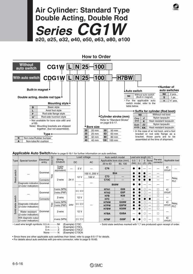
CDG1W
L 25
L
N
N 25 H7BW
Built-in magnet
20253240
506380
100
Bore size20 mm25 mm32 mm40 mm
50 mm63 mm80 mm
100 mm
Number ofauto switches
NilSn
2 pcs.1 pc.
“n” pcs.
Nil Without auto switch(Built-in magnet)
Auto switch
Cylinder stroke (mm)Refer to “Standard Stroke” on page 6-5-17.
CG1W
Basic styleAxial foot style
Rod side flange styleRod side trunnion style
Mounting styleBLFU
∗
100
100
Suffix for cylinder (Rod boot)
TypeNA
Non-lube/Rubber bumperNon-lube/Air cushion
Double acting, double rod type
NilJKJJKK
Oneend
Bothends
Without rod bootNylon tarpaulin
Heat resistant tarpaulinNylon tarpaulin
Heat resistant tarpaulin
Special functionType Electricalentry
Grommet
Grommet
Grommet
Grommet
Indic
ator
light
Wiring (Output)
2-wire
3-wire(NPN
equivalent)
Load voltage
—
ACDC
Auto switch model
C76
B54C73
C73C
B59W
Lead wire length (m) ∗
0.5(Nil)
3(L)
5(Z)
�
�
�
�
�
�
�
�
—
�
�
�
ICcircuit
Relay, PLC
Applicable load
Applicable Auto Switch/Refer to page 6-16-1 for further information on auto switches.
• Since there are other applicable auto switches than listed, refer to page 6-5-17 for details.• For details about auto switches with pre-wire connector, refer to page 6-16-60.
20 to 63
—
——
80, 100
—
5 V
100 V, 200 V
100 V
—
12 V
—
5 V, 12 V
12 V
5 V, 12 V
12 V
5 V, 12 V
—
—
24 VConnector
Connector
Diagnostic indication(2-color indication)
With diagnostic output(2-color indication)
Water resistant(2-color indication)
Diagnostic indication(2-color indication)
—
—
Yes
Yes
2-wire
3-wire (NPN)3-wire (PNP)
2-wire
3-wire (NPN)3-wire (PNP)
4-wire (NPN)
24V
ICcircuit
—
ICcircuit
—
ICcircuit
Relay, PLC
Applicable bore size (mm)
Ree
d sw
itch
Sol
id s
tate
sw
itch
None(N)
Pre-wire connector
—
——�
—
———
∗ Solid state switches marked with “�” are produced upon receipt of order.
—
How to Order
∗ For the applicable auto switch model, refer to the table below.
∗ In the case of w/ rod boot, and a foot bracket or rod side flange as a bracket, those parts are to be assembled at the time of shipment.
∗ Lead wire length symbols: 0.5 m ·········· Nil (Example) C73C 3 m ·········· L (Example) C73CL5 m ·········· Z (Example) C73CZ
None ·········· N (Example) C73CN
∗ Not available for bore size ø80 and ø100.
Note) Mounting brackets are shipped together, (but not assembled).
With auto switch
Air Cylinder: Standard TypeDouble Acting, Double Rod
Series CG1Wø20, ø25, ø32, ø40, ø50, ø63, ø80, ø100
Without auto switchWithoutauto switch
H7A1H7A2H7BH7C
H7NWH7PWH7BW
H7BA
H7NF
G59G5PK59—
G59WG5PWK59W
G5BA
G59F
�
�
�
�
�
�
�
�
�
�
—
�
�
�
�
�
�
�
�
�
—
———�
———
—
—
—
�
�
�
—�
�
�
�
�
�
�
�
�
�
�
�
�
—
�
6-5-16

Up to 1000 mm
Up to 1500 mm
Rod Boot MaterialWith Auto SwitchSymbol
J
K
Rod boot material
Nylon tarpaulin
Heat resistant tarpaulin
Maximum ambient temperature
70°C
110°C ∗
∗ Not available for bore size ø80 and ø100.∗∗ Pin and snap ring are shipped together with double knuckle joint.
Accessory
Mounting
Standard equipment
Option
Rod end nut
Single knuckle joint
�
�
�
—
�
Axial foot style
Rod sideflange style
Rod sidetrunnion style
Standard Stroke
Bore size (mm)
20
25
32
40
50, 63
80
100
Standard stroke (mm) (1) Long stroke (mm)
201 to 350
301 to 400
301 to 450
301 to 800
301 to 1200
301 to 1400
301 to 1500
�∗
Maximummanufacturable
stroke
1500
∗ Rod side trunnion style is not available for bore sizes ø80 and ø100.
Specifications
Action
Type
Fluid
Proof pressure
Maximum operating pressure
Minimum operating pressure
Ambient and fluid temperature
Piston speed
Stroke length tolerance
Thread tolerance
Cushion
Mounting ∗
20 25 32 40 50 63 80 100
st +1.80
st +1.40
Basic style, Axial foot style, Rod side flange style, Rod side trunnion style
50 to 1000 mm/s
Up to 1000 mm
Up to 1200 mm st +1.8 0
st +1.4 0
50 to 700 mm/s
Type Model Features
Without indicator light
—Without indicator light
Applicable bore size (mm)
20 to 40
20 to 100
Electrical entry
D-C80D-C80CD-B53D-B64
Grommet Connector
Grommet
Other than the applicable auto switches listed in “How to Order”, the following auto switches can be mounted.For detailed specifications, refer to page 6-16-1.
∗ Timer equipped type, solid state auto switch (D-G5NTL) is also available. ∗ Wide range detection type, solid state auto switch (D-G5NBL) is also available.∗ With pre-wire connector is available for D-G5NTL and D-G5NBL.
Reed switch
-XA�
-XB6
-XB7
-XC6
-XC13
-XC18
-XC22
-XC37
Change of rod end shape
Heat resistant cylinder (150°C)
Cold resistant cylinder
Piston rod and rod end nut made of stainless steel
Auto switch rail mounting style
NPT finish piping port
Fluoro rubber seals
Large throttle diameter of connecting port
Symbol Specifications
Made to Order Specifications(For details, refer to page 6-17-1.)
JIS Class 2
Note 1) Other intermediate strokes can be manufactured upon receipt of order. Spacers are not used for the intermediate strokes.
Note 2) Long stroke applies to the axial foot style and the rod side flange style. If other mounting brackets are used, or the length exceeds the long stroke limit, the stroke should be determined based on the stroke selection table in the technical data.
Double acting: Auto switch can be mounted for double rod. For detailed specifications, refer to pages 6-5-13 to 6-5-14.
JIS Symbol
Double acting, Double rod
Non-lube
Air
1.5 MPa
1.0 MPa
0.8 MPa
Without auto switch: –10 to 70°C (No freezing)
With auto switch: –10 to 60°C (No freezing)
Rubber bumper, Air cushion
∗∗
Bore size (mm)
Basicstyle
Pivot bracket ∗
Rod boot
Double knuckle joint(With pin)
25, 50, 75, 100, 125, 150, 200250, 300
25, 50, 75, 100, 125, 150, 200
∗ Maximum ambient temperature for the rod boot itself.
�
�
�
�
�
�
�
—
�
�
�
�
—
�
6-5-17
Series CG1WAir Cylinder: Standard TypeDouble Acting, Double Rod
CJ1
CJP
CJ2
CM2
CG1
MB
MB1
CA2
CS1
C76
C85
C95
CP95
NCM
NCA
D-
-X
20-
Data

Weight (kg)
Bore size (mm)
Bas
ic w
eigh
t Basic style
Axial foot style
Flange style
Trunnion style
Pivot bracket
Single knuckle joint
Double knuckle joint (With pin)
Additional weight per each 50 mm of stroke
Additional weight with air cushion
20
0.13
0.24
0.21
0.14
0.08
0.05
0.05
0.07
0.01
25
0.22
0.35
0.32
0.24
0.09
0.09
0.09
0.10
0.01
32
0.33
0.49
0.47
0.36
0.17
0.09
0.09
0.13
0.02
40
0.55
0.77
0.75
0.60
0.25
0.10
0.13
0.23
0.02
50
1.02
1.50
1.36
1.16
0.44
0.22
0.26
0.34
0.03
63
1.37
2.09
1.87
1.51
0.80
0.22
0.26
0.38
0.03
80
2.64
3.60
3.35
—
—
0.39
0.64
0.54
0.09
100
4.09
5.84
5.44
—
—
0.57
1.31
0.77
0.10
Calculation: (Example) CG1WLN32-100 (Foot style, ø32, 100 st)• Basic weight············0.49 (Foot, ø32) • Cylinder stroke······100 st• Additional weight··········0.13/50 st 0.49 + 0.13 x 100/50 = 0.75 kg
Be sure to read before handling. Refer to pages 6-20-3 to 6-20-6 for Safety Instructions and Actuator Precautions.
!7
!8
!9
Component PartsNo.q
w
e
r
t
y
u
i
o
!0
!1
!2
!3
!4
!5
!6
Description MaterialAluminum alloyAluminum alloyAluminum alloyCarbon steel ∗
Oil-impregnated sintered alloyUrethaneUrethane
Rolled steelNBR
UrethaneBrass
Rolled steelRolled steelCarbon steel
UrethaneNBRNBRNBRNBRNBRNBR
NoteClear hard anodized
Hard anodizedChromated
Hard chrome platedø40 and larger are lead-bronze casted
ø40 or larger: The same as bumper ANickel plated
ø40 or more ∗
Electroless nickel platedElectroless nickel plated
Nickel plated
Rod coverCylinder tubePiston Piston rodBushing Bumper ABumper BRod end nutPiston gasketPiston holderCushion ringCushion valveValve retainer Lock nutCushion sealCushion ringCushion valvePiston sealTube gasketValve sealValve retaining gasket
@0
@1
With rubber bumper
With air cushion
Construction
Note) In the case of cylinders with auto switches, magnets are installed in the piston.∗ The material is stainless steel on auto switch equipped styles ø20 and ø25.
Replacement Parts/Seal kits are the same as standard type, double acting, single rod. Refer to page 6-5-7.
Precautions
ø80, ø100 ø40 to ø100
ø40 to ø100
Series CG1W
6-5-18

Air-hydro Copper-free
Mounting style Mounting styleBore size Stroke Bore size StrokeCG1W H
Air-hydro
Low pressure hydraulic cylinder of 1.0 MPa or less. When used together with a Series CC air-hydro unit, constant and low speed actuation and intermediate stopping similar to hydraulic units are possible with the use of valves and other pneumatic equipment.
Bore size (mm)ActionFluidProof pressureMax. operating pressureMin. operating pressurePiston speedCushionAmbient and fluid temperatureThread toleranceStroke length tolerance
Mounting
Specifications SpecificationsType Air-hydro
20, 25, 32, 40, 50, 63Double acting
Turbine oil1.5 MPa 1.0 MPa 0.18 MPa
15 to 300 mm/sNone
5 to 60°CJIS Class 2
Up to 1000 mm, Up to 1200 mm
∗ Auto switch can be mounted.
Basic style, Axial foot style
Rod side flange style, Rod side trunnion style
st +1.4 0
st +1.8 0
Type20-CG1W
Copper-freeThe type which prevents copper based ions from generating by changing the copper based materials into electroless nickel plated treatment or non-copper materials in order to eliminate the effects by copper based ions or fluororesins over the color cathode ray tube.
ActionFluidMax. operating pressureMin. operating pressure
Cushion
Piston speed
Mounting ∗
Bore size (mm) 20, 25, 32, 40, 50, 63, 80, 100Double acting
Air1.0 MPa 0.08 MPa
With rubber bumperWith air cushion50 to 1000 mm/s50 to 700 mm/s
Type NType A
ø20 to 63ø80, ø100
Bore size (mm)
S
ZZ
20
77
147
25
77
157
32
79
159
40
87
187
50
102
218
63
102
218
Basic style, Axial foot style
Rod side flange style, Rod side trunnion style
Other dimensions are the same as double rod standard type (page 6-5-20).
A
1822223035354040
AL
15.519.519.52732323737
B1
1317171927273241
C
1416.5202632385060
D
810121620202530
E
1214182530324050
F
22222233
GA
1212121314142020
H
3540405058587171
H1
5668
11111316
I
26313847587289
110
J
M4 x 0.7 depth 7M5 x 0.8 depth 7.5M5 x 0.8 depth 8M6 x 1 depth 12M8 x 1.25 depth 16M10 x 1.5 depth 16M10 x 1.5 depth 22M12 x 1.75 depth 22
K
5 5.5 5.5 6 7 71010
KA
68
101418182226
20253240506380
100
20253240506380
100
Bore size(mm)
Bore size(mm) MM
M8 x 1.25M10 x 1.25M10 x 1.25M14 x 1.5M18 x 1.5M18 x 1.5M22 x 1.5M26 x 1.5
NA
24 29 35.5 44 55 69 80100
P
M5 x 0.8M5 x 0.8Rc 1/8Rc 1/8Rc 1/4Rc 1/4Rc 3/8Rc 1/2
S
77777987
102102122122
TA
111111121313——
TC ∗∗
M5 x 0.8M6 x 0.75M8 x 1.0
M10 x 1.25M12 x 1.25M14 x 1.5
——
ZZ
147157159187218218264264
WA
1616161618182222
WH
232528.53340.547.560.571
Wθ
30° 30° 25° 20°20°20°20°20°
Up to 200Up to 300Up to 300Up to 300Up to 300Up to 300Up to 300Up to 300
Standard strokerange (mm)
201 to 350301 to 400301 to 450301 to 800
301 to 1200301 to 1200301 to 1400301 to 1500
Long strokerange (mm)
∗ For the one with rod boot, refer to w/ rubber bumper.
øø
ø
øø
Basic Style with Air Cushion: CG1WBA
∗ For mounting brackets, refer to page 6-5-21.
∗∗ Trunnion mounting taps with width across flats NA are not attached for bore sizes ø80 and ø100.
∗ Rod side trunnion style is not available for bore size ø80 and ø100.Other dimensions are the same as double rod standard type (page 6-5-20).
∗ Auto switch capable
Width acrossflats B1
S + Stroke H + StrokeZZ + 2 stroke
6-5-19
Series CG1WAir Cylinder: Standard TypeDouble Acting, Double Rod
CJ1
CJP
CJ2
CM2
CG1
MB
MB1
CA2
CS1
C76
C85
C95
CP95
NCM
NCA
D-
-X
20-
Data

With rod boot at one end
With rod boot at both ends
øø
ø
ø
ø
ø
ø ø
ø
l
l
A
1822223035354040
AL C D E
1214182530324050
F
22222233
GA
1212121314142020
I J
M4 x 0.7 depth 7M5 x 0.8 depth 7.5M5 x 0.8 depth 8M6 x 1 depth 12
M8 x 1.25 depth 16M10 x 1.5 depth 16M10 x 1.5 depth 22M12 x 1.75 depth 22
K KA MM
M8 x 1.25M10 x 1.25M10 x 1.25M14 x 1.5M18 x 1.5M18 x 1.5M22 x 1.5M26 x 1.5
NA
24 29 35.5 44 55 69 80100
P
1/81/81/81/81/41/43/81/2
S
77777987
102102122122
20253240506380
100
Bore size(mm)
TA
111111121313——
TC
M5 x 0.8M6 x 0.75M8 x 1.0
M10 x 1.25M12 x 1.25M14 x 1.5
——
H3540405058587171
Without rod boot With rod boot on one side ∗ZZ147157159187218218264264
e3030353540405262
f 161717171718107
h5562627078788080
IJ2732384859725971
JH JW l ZZ167179181207238238273273
77777987
102102
ZZ
147157159187218218
With rod boot on both sides ∗ZZ187201203227258258282282
20253240506380
100
Bore size(mm)
202532405063
Bore size(mm)
Air-hydro
stro
ke0.
25
B1
1317171927273241
H1
Basic Style with Rubber Bumper: CG1WBN
Width across flats B1
S + Stroke
S + Stroke
ZZ + 2 strokeH + Stroke
2-Rc P
h + l
h + l
ZZ + l + 2 stroke
ZZ + 2 (l + Stroke)
l + Strokeh + l + Stroke
Stroke range(mm)
Up to 350Up to 400Up to 450Up to 800Up to 1200Up to 1200Up to 1400Up to 1500
∗ The minimum stroke with rod boot is 20 mm. ∗∗ Trunnion mounting taps with width across flats NA are not attached for bore sizes ø80 and ø100.
5 5.5 5.5 6 7 71010
68
101418182226
26313847587289
110
5668
11111316
810121620202530
1416.5202632385060
15.519.519.52732323737
∗∗
(14.5)(17.5)(19.5)(22.5)(25)(25)
(11.5)(11.5)(11.5)(13)(13)(13)
——
——
S
Series CG1W
6-5-20

ø
Axial foot style: CG1WLN
Rod side flange style: CG1WFN
Rod side trunnion style: CG1WUN
ø
ø
ø
∗
H
Bore size(mm)
20253240506380
100
Strokerange (mm)
Up to 350Up to 400Up to 450Up to 800
Up to 1200Up to 1200Up to 1400Up to 1500
B
34 38.5 45 54.5 70.5 82.5101121
Bore size(mm)
20253240506380
100
Strokerange (mm)
Up to 350Up to 400Up to 450Up to 800
Up to 1200Up to 1200Up to 1400Up to 1500
B
404453617692
104128
E
1214182530324050
F
22222233
FX
28323846587082
100
FD
5.5 5.5 6.6 6.6 9111114
FT
677899
1114
H
3540405058587171
LC
44445566
LD
6677
10121114
LH
2022253040455565
LS
5353536067677474
LT
33334.54.54.56
LX
323644546682
100120
LZ
4449587186
106125150
M
33.53.545557
W X
15151616.5222228.530
Y
7 7 8 8.511131416
Z
47525363.575.575.59595
Bore size(mm)
202532405063
Stroke range(mm)
Up to 200Up to 300Up to 300Up to 500Up to 600Up to 600
Bore size(mm)
202532405063
TT
3.23.24.54.568
TV
(35.8)(39.8)(49.4)(58.4)(72.4)(90.4)
TW
424248566474
TX
162022303646
TY
282828303646
TZ Without rod boot
465151627171
ZWith rod boot
66 + l73 + l73 + l82 + l91 + l91 + l
B
3845.55463.57996
TDe8 TE
101010102020
TF
5.5 5.5 6.6 6.6 911
TH
253035405060
TR
394354.565.58098
TS
283340496074
∗ End boss is machined on the flange for øE.∗ Other dimensions are the same as basic style.
∗ Consists of pin, flat washer and hexagon socket head cap bolt.∗ Other dimensions are the same as basic style.
81012141618
–0.025–0.047
–0.025–0.047
–0.032–0.059
–0.032–0.059
–0.032–0.059
–0.032–0.059
Foot Style
Rod Side Flange Style
Rod Side Trunnion Style
∗ Other dimensions are the same as basic style.
Mounting bracketBore size (mm)
Axial foot ∗FlangeTrunnion pin
Pivot bracket
Auto switchmodel
D-C7/C8
D-H7
D-B5/B6
D-G5/K5
20CG-L020CG-F020CG-T020CG-020
-24A
Bore size (mm)
20
BMA2-020
BA-01
25
BMA2-025
BA-02
32
BMA2-032
BA-32
40
BMA2-040
BA-04
50
BMA2-050
BA-05
63
BMA2-063
BA-06
80
—
BA-08
100
—
BA-10
25CG-L025CG-F025CG-T025CG-025
-24A
32CG-L032CG-F032CG-T032CG-032
-24A
40CG-L040CG-F040CG-T040CG-040
-24A
50CG-L050CG-F050CG-T050CG-050
-24A
63CG-L063CG-F063CG-T063CG-063
-24A
80CG-L080CG-F080
—
—
100CG-L100CG-F100
—
—
∗ Order two foot brackets per cylinder. ∗∗ Mounting bolts are shipped together for foot style and flange style.
Mounting Bracket Part No.
Auto Switch Mounting Bracket Part No.
With Mounting Bracket
∗ Mounting screws set made of stainless steelThe following set of mounting screws made of stainless steel is also available. Use it in accordance with the operating environment. (A switch mounting band is not included, so please order it separately.)
BBA3: For D-B5/B6/G5/K5BBA4: For D-C7/C8/H7
• D-G5BAL and D-H7BAL switches are set on the cylinder with the stainless steel screws above when shipped.When only a switch is shipped independently, BBA3 or BBA4 screws are attached.
LS + StrokeZZ + 2 stroke
ZZ + 2 stroke
2-øLCKnock pin position
Bracket mounting range
2-ø
TD
ø8
(Pin
O.D
.)
1010101017.517.52020
47.6 53 67.7 78.7 98.6119.2
+0.100 øTE
B
6-5-21
Series CG1WAir Cylinder: Standard TypeDouble Acting, Double Rod
CJ1
CJP
CJ2
CM2
CG1
MB
MB1
CA2
CS1
C76
C85
C95
CP95
NCM
NCA
D-
-X
20-
Data
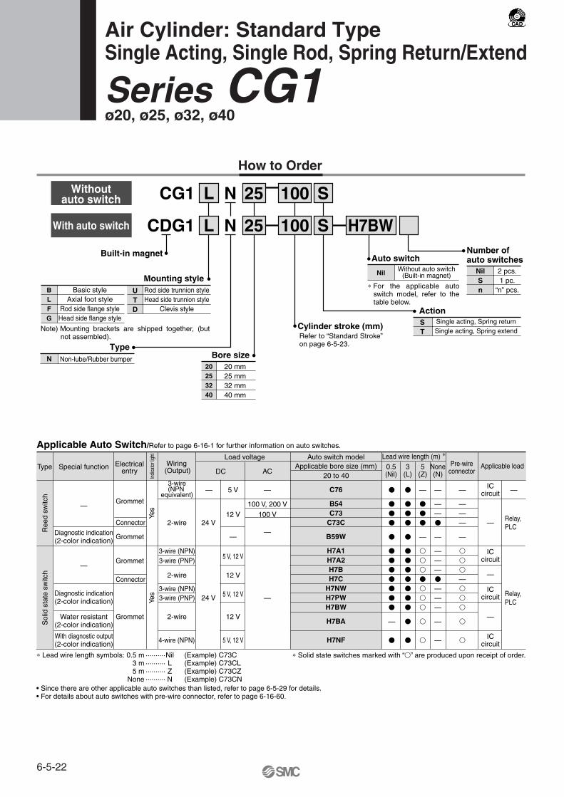
CDG1
L 25
L
N
N 25
S
S H7BWBuilt-in magnet
20253240
Bore size20 mm25 mm32 mm40 mm
NilSn
2 pcs.1 pc.
“n” pcs.
Nil Without auto switch(Built-in magnet)
Auto switch
Cylinder stroke (mm)
CG1
Basic styleAxial foot style
Rod side flange styleHead side flange style
Mounting styleBLFG
Rod side trunnion styleHead side trunnion style
Clevis style
UTD
100
100
TypeN Non-lube/Rubber bumper
Single acting, Spring returnSingle acting, Spring extend
ST
Action
Type Electricalentry
Grommet
Grommet
Grommet
Grommet
Indi
cato
r lig
ht
Wiring (Output)
2-wire
3-wire(NPN
equivalent)
Load voltage
—
ACDC
Auto switch model
C76
B54C73
C73C
B59W
H7A1H7A2H7BH7C
H7NWH7PWH7BW
H7BA
H7NF
Lead wire length (m) ∗
0.5(Nil)
3(L)
5(Z)
�
�
�
�
�
�
�
�
�
�
�
�
—
�
�
�
�
�
�
�
�
�
�
�
�
�
�
�
—
�
�
�
—
�
�
�
�
�
�
�
�
�
ICcircuit
Applicable load
Applicable Auto Switch/Refer to page 6-16-1 for further information on auto switches.
• Since there are other applicable auto switches than listed, refer to page 6-5-29 for details.• For details about auto switches with pre-wire connector, refer to page 6-16-60.
20 to 40
—
5 V
100 V, 200 V
100 V
—
12 V
—
5 V, 12 V
12 V
5 V, 12 V
12 V
5 V, 12 V
—
—
24 V
Yes
Yes
Connector
Connector
Special function
Diagnostic indication(2-color indication)
With diagnostic output(2-color indication)
Water resistant(2-color indication)
Diagnostic indication(2-color indication)
—
—
2-wire
3-wire (NPN)3-wire (PNP)
2-wire
3-wire (NPN)3-wire (PNP)
4-wire (NPN)
24 V
ICcircuit
—
ICcircuit
—
ICcircuit
Applicable bore size (mm)
Ree
d sw
itch
Sol
id s
tate
sw
itch
None(N)
Pre-wireconnector
—
——�
—
———�
———
—
—
—
———
—
�
�
�
—�
�
�
�
�
∗ Solid state switches marked with “�” are produced upon receipt of order.
Relay, PLC
Relay, PLC
—
How to Order
∗ For the applicable auto switch model, refer to the table below.
∗ Lead wire length symbols: 0.5 m ··········Nil (Example) C73C 3 m ·········· L (Example) C73CL5 m ·········· Z (Example) C73CZ
None ·········· N (Example) C73CN
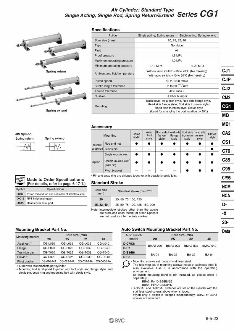
Air Cylinder: Standard TypeSingle Acting, Single Rod, Spring Return/Extend
Series CG1ø20, ø25, ø32, ø40
Refer to “Standard Stroke” on page 6-5-23.
Number ofauto switches
Note) Mounting brackets are shipped together, (but not assembled).
With auto switch
Withoutauto switch
6-5-22
Spring extend
Rod end nut
Clevis pin
Single knuckle joint
Double knuckle joint(With pin)
Pivot bracket
�
—
�
�
—
�
—
�
�
—
�
—
�
�
—
�
—
�
�
—
�
—
�
�
�
�
—
�
�
�
�
�
�
�
�
Standard Stroke
Accessory
Mounting
Bore size(mm)
20
25, 32, 40
Standard stroke (mm) Note)
25, 50, 75, 100, 125
25, 50, 75, 100, 125, 150, 200
Standard equipment
Option
Basicstyle
Axial footstyle
Rod sideflangestyle
Head sideflangestyle
Rod sidetrunnion
style
Head sidetrunnion
style
Clevis style
∗ Pin and snap ring are shipped together with double knuckle joint.
∗
Mounting Bracket Part No.
Mounting bracket
Axial foot ∗
Flange
Trunnion pin
Clevis ∗
Pivot bracket
20CG-L020
CG-F020
CG-T020
CG-D020
CG-020-24A
25CG-L025
CG-F025
CG-T025
CG-D025
CG-025-24A
32CG-L032
CG-F032
CG-T032
CG-D032
CG-032-24A
40CG-L040
CG-F040
CG-T040
CG-D040
CG-040-24A
Bore size (mm)
Auto Switch Mounting Bracket Part No.Auto switch
model
D-C7/C8
D-H7
D-B5/B6
D-G5
20
BMA2-020
BA-01
25
BMA2-025
BA-02
32
BMA2-032
BA-32
40
BMA2-040
BA-04
Bore size (mm)
Specifications
Bore size (mm)
Type
Fluid
Proof pressure
Maximum operating pressure
Minimum operating pressure
Ambient and fluid temperature
Piston speed
Stroke length tolerance
Thread tolerance
Cushion
Mounting
20, 25, 32, 40
Non-lube
Air
1.5 MPa
1.0 MPa
Without auto switch: –10 to 70°C (No freezing)
With auto switch: –10 to 60°C (No freezing)
50 to 1000 mm/s
Up to 200 mm
JIS Class 2
Rubber bumper
Single acting, Spring extendSingle acting, Spring return
0.23 MPa0.18 MPa
st +1.4 0
Basic style, Axial foot style, Rod side flange style, Head side flange style, Rod side trunnion style,
Head side trunnion style, Clevis style(Used for changing the port location by 90°.)
-XC6
-XC18
-XC20
Piston rod and rod end nut made of stainless steel
NPT finish piping port
Head cover axial port
Symbol Specifications
Made to Order Specifications(For details, refer to page 6-17-1.)
∗ Order two foot brackets per cylinder. ∗∗ Mounting bolt is shipped together with foot style and flange style, and
clevis pin, snap ring and mounting bolt with clevis style.
∗ Mounting screws set made of stainless steelThe following set of mounting screws made of stainless steel is also available. Use it in accordance with the operating environment. (A switch mounting band is not included, so please order it separately.)
BBA3: For D-B5/B6/G5BBA4: For D-C7/C8/H7
• D-G5BAL and D-H7BAL switches are set on the cylinder with the stainless steel screws above when shipped. When only a switch is shipped independently, BBA3 or BBA4 screws are attached.
Note) Intermediate strokes other than the above are produced upon receipt of order. Spacers are not used for intermediate strokes.
Spring return
Spring extend
Action
JIS SymbolSpring return
6-5-23
Series CG1Air Cylinder: Standard TypeSingle Acting, Single Rod, Spring Return/Extend
CJ1
CJP
CJ2
CM2
CG1
MB
MB1
CA2
CS1
C76
C85
C95
CP95
NCM
NCA
D-
-X
20-
Data

Calculation: (Example) CG1LN20-100S (Foot style, ø20, 100 st)• Basic weight·····0.28 kg (ø20) • Mounting bracket weight·····0.11 kg (Foot)
0.28 + 0.11 = 0.39 kg
Weight (kg)
Spring return
Bore size (mm)
Basic
weight
Mounting bracketweight
Accessory bracket
25 stroke
50 stroke
75 stroke
100 stroke
125 stroke
150 stroke
200 stroke
Axial foot style
Flange style
Trunnion style
Clevis style
Pivot bracket
Single knuckle joint
Double knuckle (With pin)
25 stroke
50 stroke
75 stroke
100 stroke
125 stroke
150 stroke
200 stroke
Axial foot style
Flange style
Trunnion style
Clevis style
Pivot bracket
Single knuckle joint
Double knuckle (With pin)
20
0.17
0.19
0.26
0.28
0.35
—
—
0.11
0.08
0.01
0.05
0.08
0.05
0.05
25
0.27
0.30
0.40
0.43
0.53
0.56
0.69
0.13
0.10
0.02
0.08
0.09
0.09
0.09
32
0.40
0.45
0.58
0.62
0.76
0.81
0.98
0.16
0.14
0.03
0.15
0.17
0.09
0.09
40
0.63
0.71
0.91
0.99
1.20
1.28
1.56
0.22
0.20
0.05
0.23
0.25
0.10
0.13
Calculation: (Example) CG1LN20-100T (Foot style, ø20, 100 st)• Basic weight······0.26 kg (ø20) • Mounting bracket weight····0.11 kg (Foot)
0.26 + 0.11 = 0.37 kg
Spring extend
Bore size (mm)
Basicweight
Mountingbracketweight
Accessorybracket
20
0.16
0.18
0.24
0.26
0.32
—
—
0.11
0.08
0.01
0.05
0.08
0.05
0.05
25
0.25
0.28
0.37
0.40
0.48
0.50
0.63
0.13
0.10
0.02
0.08
0.09
0.09
0.09
32
0.38
0.43
0.54
0.58
0.69
0.72
0.89
0.16
0.14
0.03
0.15
0.17
0.09
0.09
40
0.59
0.67
0.83
0.91
1.08
1.12
1.40
0.22
0.20
0.05
0.23
0.25
0.10
0.13
Component PartsNo.
q
w
e
r
t
y
u
i
o
!0
!1
!2
!3
!4
!5
!6
!7
!8
!9
Description Material
Aluminum alloy
Aluminum alloy
Aluminum alloy
Carbon steel ∗
Oil-impregnated sintered alloy
Urethane
Urethane
Stainless steel
Resin
Rolled steel
NBR
Steel wire
Aluminum alloy
Aluminum alloy
Sintered metallic BC
Copper wire
NBR
NBR
NBR
Note
Clear hard anodized
Clear hard anodized
Chromated
Hard chrome plated
ø40 is lead-bronze casted
Nickel plated
Zinc chromated
Chromated
Chromated
Replacement Parts: For Single Acting, Spring Return
No. Description
Piston seal
Material
NBR
Part no.
20
PPD-20
25
PPD-25-19
32
PPD-32
40
PPD-40
Replacement Parts: For Single Acting, Spring Extend
!8
Rod cover
Tube cover
Piston
Piston rod
Bushing
Bumper A
Bumper B
Snap ring
Wear ring
Rod end nut
Piston gasket
Return spring
Spring guide
Spring seat
Element
Snap ring
Rod seal
Piston seal
Tube gasket
Construction
Single acting, Spring return
Single acting, Spring extend
Note) In the case of cylinders with auto switches, rubber magnets are installed in the piston.
∗ The material is stainless steel on auto switch equipped styles ø20 and ø25.
Replacement parts/Seal kits are the same as standard type, double acting, single rod (with rubber bumper). Refer to page 6-5-7.
Series CG1
6-5-24
6-5-25
Series CG1Air Cylinder: Standard TypeSingle Acting, Single Rod, Spring Return/Extend
CJ1
CJP
CJ2
CM2
CG1
MB
MB1
CA2
CS1
C76
C85
C95
CP95
NCM
NCA
D-
-X
20-
Data
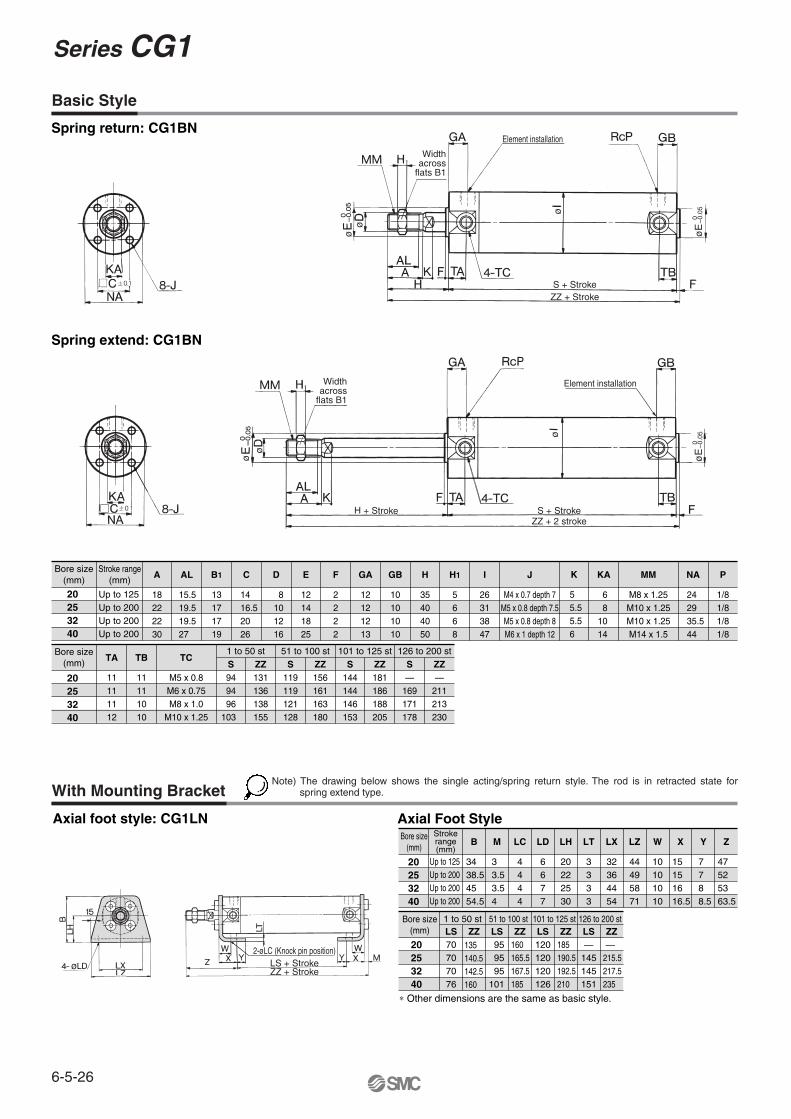
Axial foot style: CG1LN
Spring return: CG1BN
Spring extend: CG1BNø
ø
øø
øø
ø
Bore size(mm)
Strokerange(mm)
20253240
Up to 125Up to 200Up to 200Up to 200
B
3438.54554.5
M
33.53.54
LC
4444
LD
6677
LH
20222530
LT
3333
LX
32364454
LZ
44495871
W
10101010
X
15151616.5
Y
7788.5
Z
47525363.5
Bore size(mm)
20253240
LS70707076
ZZ135140.5142.5160
LS959595
101
ZZ160165.5167.5185
LS120120120126
ZZ185190.5192.5210
LS1 to 50 st 51 to 100 st 101 to 125 st 126 to 200 st
—145145151
ZZ —215.5217.5235
Axial Foot Style
∗ Other dimensions are the same as basic style.
Bore size(mm)
Stroke range(mm)
20253240
Up to 125Up to 200Up to 200Up to 200
A
18222230
AL
15.519.519.527
B1
13171719
C
1416.52026
D
8101216
E
12141825
F
2222
GA
12121213
GB
10101010
H
35404050
H1
5668
I
26313847
J
M4 x 0.7 depth 7M5 x 0.8 depth 7.5M5 x 0.8 depth 8M6 x 1 depth 12
K
55.55.56
KA
68
1014
MM
M8 x 1.25M10 x 1.25M10 x 1.25M14 x 1.5
NA
242935.544
P
1/81/81/81/8
Bore size(mm)
20253240
TA
11111112
TB
11111010
TC
M5 x 0.8M6 x 0.75M8 x 1.0
M10 x 1.25
S949496
103
ZZ131136138155
S119119121128
ZZ156161163180
S144144146153
ZZ181186188205
S1 to 50 st 51 to 100 st 101 to 125 st 126 to 200 st
—169171178
ZZ—
211213230
Basic Style
With Mounting Bracket
Widthacross
flats B1
Element installation
ZZ + StrokeS + Stroke
ZZ + Stroke
H + Stroke
LS + Stroke2-øLC (Knock pin position)
øE
–0.0
50
øE
–0.0
50
Widthacross
flats B1
Element installation
S + StrokeZZ + 2 stroke
Note) The drawing below shows the single acting/spring return style. The rod is in retracted state for spring extend type.
Series CG1
6-5-26
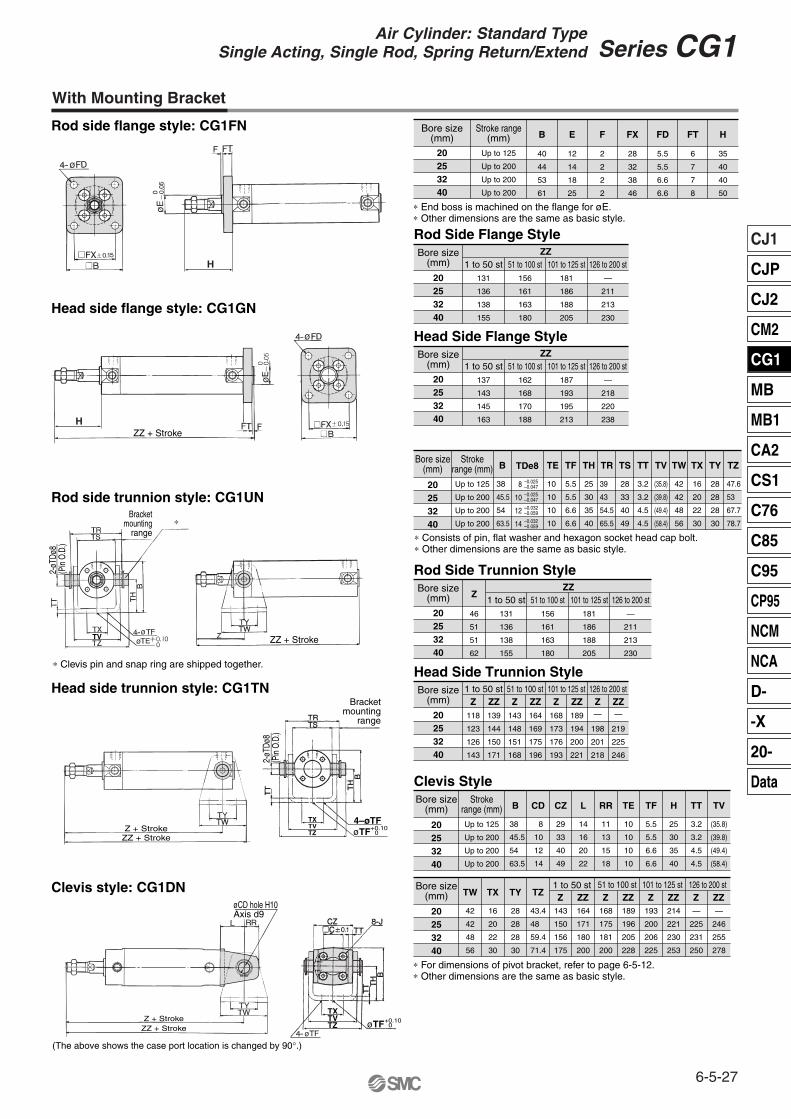
(The above shows the case port location is changed by 90°.)
Clevis style: CG1DN
Head side trunnion style: CG1TN
Rod side trunnion style: CG1UN
Head side flange style: CG1GN
Rod side flange style: CG1FN
TVTX
TXTV
TV
TZ
TZ
TV
∗ Clevis pin and snap ring are shipped together.
H
H
∗
øø
ø
ø
øø
ø
20253240
131
136
138
155
Bore size(mm)
Rod Side Flange Style
20253240
Bore size(mm)
Up to 125
Up to 200
Up to 200
Up to 200
Stroke range(mm)
1 to 50 st
40
44
53
61
12
14
18
25
2
2
2
2
28
32
38
46
5.5
5.5
6.6
6.6
6
7
7
8
B E F FX FD FT
35
40
40
50
H
20253240
Bore size(mm)
Up to 125
Up to 200
Up to 200
Up to 200
Strokerange (mm)
38
45.5
54
63.5
B
8
10
12
14
TDe8
10
10
10
10
TE
5.5
5.5
6.6
6.6
TF
25
30
35
40
TH
39
43
54.5
65.5
TR
28
33
40
49
TS
3.2
3.2
4.5
4.5
TT
(35.8)
(39.8)
(49.4)
(58.4)
TV
42
42
48
56
TW
16
20
22
30
TX
28
28
28
30
TY
47.6
53
67.7
78.7
TZ
20253240
Bore size(mm)
Up to 125
Up to 200
Up to 200
Up to 200
Strokerange (mm)
38
45.5
54
63.5
B
8
10
12
14
CD
29
33
40
49
CZ
14
16
20
22
L
11
13
15
18
RR
10
10
10
10
TE
5.5
5.5
6.6
6.6
TF
25
30
35
40
H
3.2
3.2
4.5
4.5
TT
(35.8)
(39.8)
(49.4)
(58.4)
TV
20253240
Bore size(mm)
28
28
28
30
TY
43.4
48
59.4
71.4
TZ
42
42
48
56
TW
16
20
22
30
TX
143
150
156
175
Z164
171
180
200
ZZ168
175
181
200
Z189
196
205
228
ZZ193
200
206
225
Z214
221
230
253
ZZ—
225
231
250
Z1 to 50 st 51 to 100 st 101 to 125 st 126 to 200 st
—
246
255
278
ZZ
156
161
163
180
51 to 100 st181
186
188
205
101 to 125 st—
211
213
230
126 to 200 stZZ
20253240
137
143
145
163
Bore size(mm)
Head Side Flange Style
1 to 50 st162
168
170
188
51 to 100 st187
193
195
213
101 to 125 st—
218
220
238
126 to 200 stZZ
20253240
Bore size(mm)
Rod Side Trunnion Style
131
136
138
155
46
51
51
62
1 to 50 st156
161
163
180
51 to 100 st181
186
188
205
101 to 125 st—
211
213
230
126 to 200 stZZ
Z
20253240
118
123
126
143
Bore size(mm)
Head Side Trunnion Style
Clevis Style
Z139
144
150
171
ZZ143
148
151
168
Z164
169
175
196
ZZ168
173
176
193
Z189
194
200
221
ZZ—
198
201
218
Z—
219
225
246
ZZ1 to 50 st 51 to 100 st 101 to 125 st 126 to 200 st
∗ End boss is machined on the flange for øE.∗ Other dimensions are the same as basic style.
∗ Consists of pin, flat washer and hexagon socket head cap bolt.∗ Other dimensions are the same as basic style.
–0.025–0.047–0.025–0.047
–0.032–0.059
–0.032–0.059
∗ For dimensions of pivot bracket, refer to page 6-5-12.∗ Other dimensions are the same as basic style.
With Mounting Bracket
ZZ + Stroke
ZZ + Stroke
ZZ + Stroke
Bracketmounting
range
Bracketmounting
range
2-øT
Dø8
(Pin
O.D
.)
2-øT
Dø8
(Pin
O.D
.)
Z + Stroke
ZZ + StrokeZ + Stroke
øCD hole H10Axis d9
4–øTFøTF+0.10
0
øTF+0.100
6-5-27
Series CG1Air Cylinder: Standard TypeSingle Acting, Single Rod, Spring Return/Extend
CJ1
CJP
CJ2
CM2
CG1
MB
MB1
CA2
CS1
C76
C85
C95
CP95
NCM
NCA
D-
-X
20-
Data

D-H7�, D-H7�WD-H7NF, D-H7BAL
D-B5, D-B6, D-B59W
D-C7, D-C8
D-C73C, D-C80C
D-H7C
D-G5NTL
( ): Denotes the values of D-H7LF.
20
25
32
40
20
25
32
40
20
25
32
40
20
25
32
40
20
25
32
40
Single Acting, Spring ReturnAuto switch
model
D-C7D-C8D-C73CD-C80C
D-B5D-B6
Bore size(mm)
A
25
55
55
56
60.5
54
54
55
59.5
49
49
50
54.5
50.5
50.5
51.5
56
52
52
53
57.5
50
55
55
56
60.5
54
54
55
59.5
49
49
50
54.5
50.5
50.5
51.5
56
52
52
53
57.5
( ): Denotes the dimensions with connector.
75
80
80
81
85.5
79
79
80
84.5
74
74
75
79.5
75.5
75.5
76.5
81
77
77
78
82.5
100
80
80
81
85.5
79
79
80
84.5
74
74
75
79.5
75.5
75.5
76.5
81
77
77
78
82.5
125
105
105
106
110.5
104
104
105
109.5
99
99
100
104.5
100.5
100.5
101.5
106
102
102
103
107.5
150 200
20.5
20.5
21.5
23.5
19.5
19.5
20.5
22.5
15.5
15.5
15.5
19
16
16
17
19
17.5
17.5
18.5
20.5
30
30
31
35.5
29
29
30
34.5
24
24
25
29.5
25.5
25.5
26.5
31
27
27
28
32.5
Hs
24.5(27)
27(29.5)
30.5(33)
35(37.5)
24.5(27.5)
27(30)
30.5(33.5)
35(38)
27.5
30
33.5
38
27.5
30
33.5
38
27.5
30
33.5
38
20
25
32
40
20
25
32
40
20
25
32
40
20
25
32
40
20
25
32
40
Single Acting, Spring ExtendAuto switch
model
D-C7D-C8D-C73CD-C80C
D-B5D-B6
Bore size(mm)
B
25
45.5
45.5
46.5
48.5
44.5
44.5
45.5
47.5
39.5
39.5
40.5
42.5
41
41
42
44
42.5
42.5
43.5
45.5
50
45.5
45.5
46.5
48.5
44.5
44.5
45.5
47.5
39.5
39.5
40.5
42.5
41
41
42
44
42.5
42.5
43.5
45.5
( ): Denotes the dimensions with connector.
75
70.5
70.5
71.5
73.5
69.5
69.5
70.5
72.5
64.5
64.5
65.5
67.5
66
66
67
69
67.5
67.5
68.5
70.5
100
70.5
70.5
71.5
73.5
69.5
69.5
70.5
72.5
64.5
64.5
65.5
67.5
66
66
67
69
67.5
67.5
68.5
70.5
125
95.5
95.5
96.5
98.5
94.5
94.5
95.5
97.5
89.5
89.5
90.5
92.5
91
91
92
94
92.5
92.5
93.5
95.5
150 200Hs
24.5(27)
27(29.5)
30.5(33)
35(37.5)
24.5(27.5)
27(30)
30.5(33.5)
35(38)
27.5
30
33.5
38
27.5
30
33.5
38
27.5
30
33.5
38
D-G5NTLD-G59F
D-G5NTLD-G59F
D-H7�WD-H7�D-H7CD-H7BALD-H7NF
D-B59W
D-H7�WD-H7�D-H7CD-H7BALD-H7NF
Proper Auto Switch Mounting Position (Detection at stroke end) and Its Mounting Height
D-B59W
Auto switch≅Hs Auto switch
Auto switch
Auto switch
Auto switch
Auto switch
B
All stroke
A
All stroke
127
128
132.5
125.5
126.5
131
124
125
129.5
129
130
134.5
130
131
135.5—
— —
—
— —
— —
— —
127
128
132.5
125.5
126.5
131
124
125
129.5
129
130
134.5
130
131
135.5
117.5
118.5
120.
117.5
118.5
120.5
116
117
119
116
117
119
114.5
115.5
117.5
114.5
115.5
117.5
119.5
120.5
122.5
119.5
120.5
122.5
120.5
121.5
123.5
120.5
121.5
123.5
— —
— —
— —
— —
— —
≅Hs
≅Hs ≅Hs
≅Hs
≅Hs
Series CG1
6-5-28

Auto switch modelBore size (mm)
Operating Range
20 25 32 40
D-B59W
D-H7C
D-G5NBLD-G5NTLD-H7NF
D-H7�/H7�WD-H7BAL
Type Model Features
Without indicator light
—Without indicator light
Applicable bore size (mm)
20 to 40
Electrical entry
D-C80D-C80CD-B53D-B64
Grommet Connector
Grommet
∗ Timer equipped type, solid state auto switch (D-G5NTL) is also available.∗ Wide range detection type, solid state auto switch (D-G5NBL) is also available.∗ With pre-wire connector is available for D-G5NTL and D-G5NBL.
Reed switch
D-C7�/C80D-C73C/C80CD-B5�/B64
∗ Since this is a guideline including hysteresis, not meant to be guaranteed.(Assuming approximately ±30% dispersion)There may be the case it will vary substantially depending on an ambient environment.
10
13
4
8.554
40
8
13
4
754
35
9
14
4.5
95.54.5
40
10
14
5
1065
45
Other than the applicable auto switches listed in “How to Order”, the following auto switches can be mounted. For detailed specifications, refer to page 6-16-1.
6-5-29
Series CG1Air Cylinder: Standard TypeSingle Acting, Single Rod, Spring Return/Extend
CJ1
CJP
CJ2
CM2
CG1
MB
MB1
CA2
CS1
C76
C85
C95
CP95
NCM
NCA
D-
-X
20-
Data

CG1K
CDG1K
L
L
N
NBuilt-in magnet
Cylinder stroke (mm)
Double acting, non-rotating rod typeNilSn
2 pcs.1 pc.
“n” pcs.
Auto switch
Nil Without auto switch(Built-in magnet)Mounting style
H7BW
Bore size202532405063
20 mm25 mm32 mm40 mm50 mm63 mm
100
100
25
25
BLFGUTD
Basic styleAxial foot style
Rod side flange styleHead side flange styleRod side trunnion styleHead side trunnion style
Clevis style
CushionN
A
Non-lube/Rubber bumper
Non-lube/Air cushion(ø40 to ø63 only)
Special functionType Electricalentry
Grommet
Grommet
Grommet
Grommet
Indica
tor lig
ht
Wiring (Output)
2-wire
3-wire(NPN equivalent)
Load voltage
—
ACDC
Auto switch model
C76
B54C73
C73C
B59W
H7A1H7A2H7BH7C
H7NWH7PWH7BW
H7BA
H7NF
Lead wire length (m) ∗
0.5(Nil)
3(L)
5(Z)
�
�
�
�
�
�
�
�
�
�
�
�
—
�
�
�
�
�
�
�
�
�
�
�
�
�
�
�
—
�
�
�
—
�
�
�
�
�
�
�
�
�
ICcircuit
Relay, PLC
Applicable load
Applicable Auto Switch/Refer to page 6-16-1 for further information on auto switches.
• Since there are other applicable auto switches than listed, refer to page 6-5-31 for details.• For details about auto switches with pre-wire connector, refer to page 6-16-60.
20 to 63
—
5 V
100 V, 200 V
—
100 V12 V
—
5 V, 12 V
12 V
5 V, 12 V
12 V
5 V, 12 V
—
—
24 VConnector
Connector
Diagnostic indication(2-color indication)
With diagnostic output(2-color indication)
Water resistant(2-color indication)
Diagnostic indication(2-color indication)
—
—
Yes
Yes
2-wire
3-wire (NPN)3-wire (PNP)
2-wire
3-wire (NPN)3-wire (PNP)
4-wire (NPN)
24 V
ICcircuit
—
ICcircuit
—
ICcircuit
Relay, PLC
Applicable bore size (mm)
Ree
d sw
itch
Sol
id s
tate
sw
itch
None(N)
Pre-wireconnector
—
——�
—
———�
———
—
—
—
———
—
�
�
�
—�
�
�
�
�
∗ Solid state switches marked with “�” are produced upon receipt of order.
—
How to Order
Note) Mounting brackets are shipped together, (but not assembled).
Refer to “Standard Stroke” on page 6-5-31.
∗ For the applicable auto switch model, refer to the table below.
∗ Lead wire length symbols: 0.5 m ·········· Nil (Example) C73C 3 m ·········· L (Example) C73CL5 m ·········· Z (Example) C73CZ
None ·········· N (Example) C73CN
Air Cylinder: Non-rotating Rod TypeDouble Acting, Single Rod
Series CG1Kø20, ø25, ø32, ø40, ø50, ø63
Number ofauto switches
With auto switch
Without auto switch
6-5-30

Accessory
20
25
32
40
50, 63
Bore size (mm) Standard stroke (mm) (1) Long stroke (mm)
25, 50, 75, 100, 125, 150, 200 —
—
—
301 to 500
301 to 600
25, 50, 75, 100, 125, 150, 200, 250, 300
Rod end nut
Clevis pin
Single knuckle joint
Mounting Basicstyle
Axial footstyle
Rod sideflangestyle
Head sideflangestyle
Rod sidetrunnion
style
Head sidetrunnion
style
Clevisstyle
� � � � � � �
Standardequipment
Pivot bracket — — — — � � �
Double knuckle joint ∗(With pin)
Option
�
—
�
�
—
�
�
—
�
�
—
�
�
—
�
�
—
�
�
�
�
Standard Stroke
With Auto Switch
∗ Pin and snap ring are shipped together with double knuckle joint.
Specifications
Action
Type
Fluid
Proof pressure
Maximum operating pressure
Minimum operating pressure
Ambient and fluid temperature
Piston speed
Thread tolerance
Stroke length tolerance
Cushion
Rod non-rotating accuracy
Mounting
Double acting, Single rod
Non-lube
Air
1.5 MPa
1.0 MPa
0.05 MPa
Without auto switch: –10 to 70°C (No freezing)
With auto switch: –10 to 60°C (No freezing)
50 to 500 mm/s
JIS Class 2
Up to 600 mm
Rubber bumper, Air cushion (ø40 to ø63 only)
Basic style, Axial foot style, Rod side flange style, Head side flange style, Rod side trunnion style,
Head side trunnion style, Clevis style(Used for changing the port location by 90°.)
20
±1° ±0.8° ±0.5°
25 32 40 50 63
st +1.40
Type Model Features
Without indicator light
—
Without indicator light
Applicable bore size (mm)
20 to 63
Electrical entry
D-C80D-C80CD-B53D-B64
Grommet Connector
Grommet
∗ Timer equipped type, solid state auto switch (D-G5NTL) is also available.∗ Wide range detection type, solid state auto switch (D-G5NBL) is also available.∗ With pre-wire connector is available for D-G5NTL and D-G5NBL.
Reed switch
JIS Symbol
Non-rotating accuracyø20, ø25·········±1°ø32·················±0.8°ø40 to ø63······±0.5°
High speed operation/Long service lifePiston speed is between 50 and 500 mm/s and long service life is expected.
Can operate without lubrication. The same installation dimensions as the standard cylinder. Auto switches can also be mounted.It can be installed with auto switches to simplify the detection of the stroke position of the cylinder.
-XA�
-XC8
-XC9
-XC10
-XC11
-XC12
-XC13
-XC20
Change of rod end shape
Adjustable stroke cylinder/Adjustable extension type
Adjustable stroke cylinder/Adjustable retraction type
Dual stroke cylinder/Double rod type
Dual stroke cylinder/Single rod type
Tandem type cylinder
Auto switch rail mounting style
Head cover axial port
Symbol Specifications
Made to Order Specifications(For details, refer to page 6-17-1.)
Note 1) Intermediate strokes other than the above are produced upon receipt of order. Spacers are not used for intermediate strokes.
Note 2) The maximum limit is 1500 stroke, but the products that exceed the standard or the long stroke limit are not guaranteed.
Double acting: Auto switch can be mounted for non-rotating rod. Mounting position is the same as double acting, single rod type. Refer to page 6-5-13.
Other than the applicable auto switches listed in “How to Order”, the following auto switches can be mounted. For detailed specifications, refer to page 6-16-1.
Bore size (mm)
6-5-31
Series CG1KAir Cylinder: Non-rotating Rod TypeDouble Acting, Single Rod
CJ1
CJP
CJ2
CM2
CG1
MB
MB1
CA2
CS1
C76
C85
C95
CP95
NCM
NCA
D-
-X
20-
Data

Calculation: (Example) CG1KLN20-100(Foot style, ø20, 100 st)
Weight Copper-free
Specifications
Mounting style N20-CG1K Bore size StrokeBore size (mm)
Bas
ic w
eigh
t
20 25 32 40 50 63
0.10
0.21
0.18
0.11
0.15
0.08
0.05
0.05
0.05
—
—
0.17
0.30
0.27
0.19
0.25
0.09
0.09
0.09
0.07
—
—
0.26
0.42
0.40
0.29
0.41
0.17
0.09
0.09
0.09
—
—
0.41
0.63
0.61
0.46
0.64
0.25
0.10
0.13
0.15
0.02
0.03
0.77
1.25
1.11
0.91
1.17
0.44
0.22
0.26
0.22
0.03
0.06
1.07
1.79
1.57
1.21
1.75
0.80
0.22
0.26
0.26
0.03
0.10
Basic style
Axial foot style
Flange style
Trunnion style
Clevis style
Pivot bracket
Single knuckle joint
Double knuckle joint (With pin)
Additional weight per each 50 mm of stroke
Additional weight with air cushion
Additional weight for long stroke
Action
Fluid
Maximum operating pressure
Minimum operating pressure
Piston speed
Mounting
20, 25, 32, 40, 50, 63
Double acting
Air
1.0 MPa
0.05 MPa
50 to 500 mm/s
(kg)
• Basic weight·············0.21 (Foot, ø20)• Additional weight······0.05/50• Cylinder stroke·········1000.21 + 0.05 x 100/50 = 0.31 kg
st
st
Copper-free
Mounting Bracket Part No.Mounting bracket
Bore size (mm)
20
Axial foot ∗
Flange
Trunnion pin
Clevis ∗∗
Pivot bracket
CG-L020
CG-F020
CG-T020
CG-D020
CG-020-24A
25
CG-L025
CG-F025
CG-T025
CG-D025
CG-025-24A
32
CG-L032
CG-F032
CG-T032
CG-D032
CG-032-24A
40
CG-L040
CG-F040
CG-T040
CG-D040
CG-040-24A
50
CG-L050
CG-F050
CG-T050
CG-D050
CG-050-24A
63
CG-L063
CG-F063
CG-T063
CG-D063
CG-063-24A
Auto Switch Mounting Bracket Part No.Auto switch
modelBore size (mm)
20
D-C7/C8
D-H7
D-B5/B6
D-G5
BMA2-020
BA-01
25
BMA2-025
BA-02
32
BMA2-032
BA-32
40
BMA2-040
BA-04
50
BMA2-050
BA-05
63
BMA2-063
BA-06
The type which prevents copper based ions from generating by changing the copper based materials into electroless nickel plated treatment or non-copper materials in order to eliminate the effects by copper based ions or fluororesins over the color cathode ray tube.
∗ Order two foot brackets per cylinder. ∗∗ Mounting bolt is shipped together with foot style and flange
style, and clevis pin, snap ring and mounting bolt for clevis style.
∗ Mounting screws set made of stainless steelThe following set of mounting screws made of stainless steel is also available. Use it in accordance with the operating environment. (A switch mounting band is not included, so please order it separately.)
BBA3: For D-B5/B6/G5BBA4: For D-C7/C8/H7
• D-G5BAL and D-H7BAL switches are set on the cylinder with the stainless steel screws above when shipped. When a switch only is shipped, BBA3 or BBA4 screws are attached.
Bore size (mm)
Basic style, Axial foot style, Rod side flange style, Head side flange style, Rod side trunnion style,
Head side trunnion styleClevis style (Used for changing the port location by 90°.)
Series CG1K
6-5-32
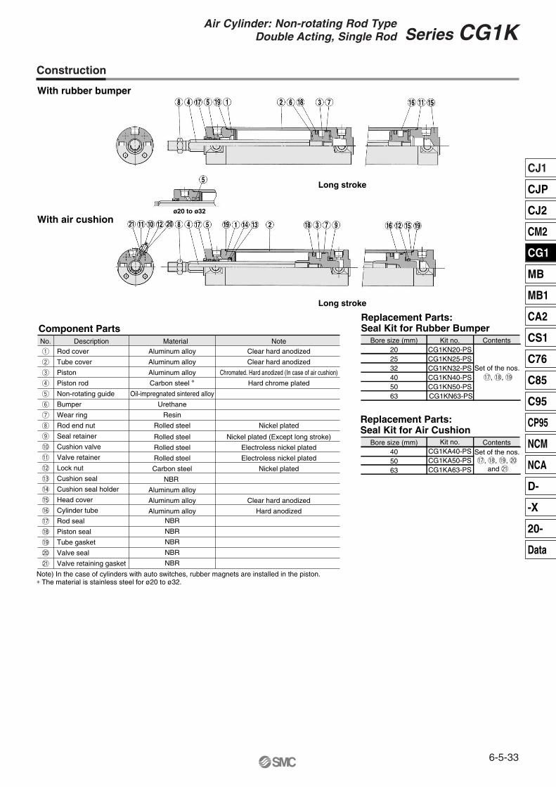
With rubber bumper
With air cushion
Long stroke
Long stroke
Component PartsDescriptionNo. Material Note
Aluminum alloy
Aluminum alloy
Aluminum alloy
Carbon steel ∗
Oil-impregnated sintered alloy
Urethane
Resin
Rolled steel
Clear hard anodized
Clear hard anodized
Chromated. Hard anodized (In case of air cushion)
Hard chrome plated
Nickel plated
q
w
e
r
t
y
u
i
!7
!8
!9
Rolled steel
Rolled steel
Rolled steel
Carbon steel
NBR
Aluminum alloy
Aluminum alloy
Aluminum alloy
Nickel plated (Except long stroke)
Electroless nickel plated
Electroless nickel plated
Nickel plated
Clear hard anodized
Hard anodized
o
!0
!1
!2
!3
!4
!5
!6
NBR
NBR
NBR
NBR
NBR@0
@1
Rod cover
Tube cover
Piston
Piston rod
Non-rotating guide
Bumper
Wear ring
Rod end nut
Seal retainer
Cushion valve
Valve retainer
Lock nut
Cushion seal
Cushion seal holder
Head cover
Cylinder tube
Rod seal
Piston seal
Tube gasket
Valve seal
Valve retaining gasket
Bore size (mm)202532405063
Kit no.CG1KN20-PSCG1KN25-PSCG1KN32-PSCG1KN40-PSCG1KN50-PS CG1KN63-PS
Contents
Replacement Parts:Seal Kit for Rubber Bumper
Bore size (mm)405063
Kit no.CG1KA40-PSCG1KA50-PSCG1KA63-PS
ContentsSet of the nos. !7, !8, !9, @0
and @1
Replacement Parts:Seal Kit for Air Cushion
Set of the nos. !7, !8, !9
Construction
Note) In the case of cylinders with auto switches, rubber magnets are installed in the piston.∗ The material is stainless steel for ø20 to ø32.
ø20 to ø32
6-5-33
Series CG1KAir Cylinder: Non-rotating Rod TypeDouble Acting, Single Rod
CJ1
CJP
CJ2
CM2
CG1
MB
MB1
CA2
CS1
C76
C85
C95
CP95
NCM
NCA
D-
-X
20-
Data

Be sure to read before handling. For Safety Instructions and Actuator Precautions, refer to pages 6-20-3 to 6-20-6.
Precautions
Bore size(mm)
Stroke range(mm) A
202532405063
Up to 200Up to 300Up to 300Up to 300(500)Up to 300(600)Up to 300(600)
182222303535
AL
15.519.519.5273232
B1
131717192727
C
1416.520263238
D
9.21112162020
E
121418253032
F
222222
GA
121212131414
GB
101010
10(13)12(14)12(14)
H
354040505858
H1
5668
1111
I
263138475872
J
M4 x 0.7 depth 7M5 x 0.8 depth 7.5M5 x 0.8 depth 8M6 x 1 depth 12
M8 x 1.25 depth 16M10 x 1.5 depth 16
KA
81010141818
MM
M8 x 1.25M10 x 1.25M10 x 1.25M14 x 1.5M18 x 1.5M18 x 1.5
NA
242935.5445569
P
1/81/81/81/81/41/4
S
696971
78(87)90(102)90(102)
TA
111111121313
TB
111110
10(12)12(13)12(13)
TC
M5 x 0.8M6 x 0.75M8 x 1.0
M10 x 1.25M12 x 1.25M14 x 1.5
ZZ
106111113
130(139)150(162)150(162)
Bore size(mm)
Allowable rotational torque(N·m or less)
P
Note) ( ): Denotes the dimensions for long stroke.
405063
ø20
0.2
ø25, ø32
0.25
ø40, ø50, ø63
0.44
Rc 1/8Rc 1/4Rc 1/4
161818
WB
3340.547.5
WθWH
20°20°20°
WA
15(16)17(18)17(18)
With Air Cushion
Caution on Handling/Disassembly
Caution
With rubber bumper: CG1KBNø20 to ø63
With air cushion: CG1KBAø40 to ø63
Basic Style
Note 1) Dimensions for each mounting bracket are the same as those for CG1 standard or long stroke model. Refer to pages 6-5-9 and 6-5-10. Also, as for the one with auto switch, it is the same as standard products of Series CDG1.
Note 2) ( ): Long stroke
1. Avoid using the air cylinder in such a way that rotational torque would be applied to the piston rod.
• If rotational torque is applied, the non-rotating guide will become deformed, thus affecting the non-rotating accuracy.
• To screw a bracket or a nut onto the piston rod, make sure to retract the piston rod entirely, and place a wrench over the flat portion of the rod that protrudes.
2. When replacing rod seals, please contact SMC.Air leakage may be happened, depending on the position in which a rod seal is fitted. Thus, please contact SMC when replacing them.
Tighten it by giving consideration to prevent the tightening torque from being applied to the non-rotating guide.
ø
ø
ø
ø
Widthacross
flats B1
2-Rc P
S + StrokeZZ + Stroke
ø
ø
øø
Width acrossflats B1
S + StrokeZZ + Stroke
Series CG1K
6-5-34
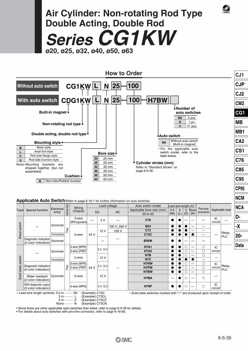
CG1KW
CDG1KW
L
L
N
N
Non-rotating rod type
Cylinder stroke (mm)
Built-in magnet
Double acting, double rod type
NilSn
2 pcs.1 pc.
“n” pcs.
Auto switch
Nil Without auto switch(Built-in magnet)Mounting style
H7BW
100
100
25
25
Bore size 202532405063
20 mm25 mm32 mm40 mm50 mm63 mm
BLFU
Basic styleAxial foot style
Rod side flange styleRod side trunnion style
Cushion N Non-lube/Rubber bumper
Special functionType Electricalentry
Grommet
Grommet
Grommet
Grommet
Indica
tor lig
ht
Wiring(Output)
2-wire
3-wire(NPN equivalent)
Load voltage
—
ACDC
Auto switch model
C76
B54C73
C73C
B59W
H7A1H7A2H7BH7C
H7NWH7PWH7BW
H7BA
H7NF
Lead wire length (m) ∗0.5(Nil)
3(L)
5(Z)
�
�
�
�
�
�
�
�
�
�
�
�
—
�
�
�
�
�
�
�
�
�
�
�
�
�
�
�
—
�
�
�
—
�
�
�
�
�
�
�
�
�
ICcircuit
Relay, PLC
Applicable load
Applicable Auto Switch/Refer to page 6-16-1 for further information on auto switches.
• Since there are other applicable auto switches than listed, refer to page 6-5-39 for details.• For details about auto switches with pre-wire connector, refer to page 6-16-60.
20 to 63
—
5 V
100 V, 200 V
100 V
—
12 V
—
5 V, 12 V
12 V
5 V, 12 V
12 V
5 V, 12 V
—
—
24 V
Yes
Yes
Connector
Connector
Diagnostic indication(2-color indication)
With diagnostic output(2-color indication)
Water resistant(2-color indication)
Diagnostic indication(2-color indication)
—
—
2-wire
3-wire (NPN) 3-wire (PNP)
2-wire
3-wire (NPN) 3-wire (PNP)
4-wire (NPN)
24 V
ICcircuit
—
ICcircuit
—
ICcircuit
Relay, PLC
Applicable bore size (mm)
Ree
d sw
itch
Sol
id s
tate
sw
itch
None(N)
Pre-wireconnector
—
——�
—
———�
———
—
—
—
———
—
�
�
�
—�
�
�
�
�
∗ Solid state switches marked with “�” are produced upon receipt of order.
—
How to Order
Refer to “Standard Stroke” on page 6-5-36.
∗ For the applicable auto switch model, refer to the table below.
Note) Mounting brackets are shipped together, (but not assembled).
∗ Lead wire length symbols: 0.5 m ·········· Nil (Example) C73C 3 m ·········· L (Example) C73CL5 m ·········· Z (Example) C73CZ
None ·········· N (Example) C73CN
Number of auto switches
With auto switch
Without auto switch
Air Cylinder: Non-rotating Rod TypeDouble Acting, Double Rod
Series CG1KWø20, ø25, ø32, ø40, ø50, ø63
6-5-35
CJ1
CJP
CJ2
CM2
CG1
MB
MB1
CA2
CS1
C76
C85
C95
CP95
NCM
NCA
D-
-X
20-
Data

Accessory
20
25
32
40
50, 63
Mounting Basicstyle
Axialfoot style
Rod sideflange style
Rod sidetrunnion style
Bore size (mm) Standard stroke (mm) Long stroke (mm)
25, 50, 75, 100, 125, 150, 200 —
—
—
301 to 500
301 to 600
25, 50, 75, 100, 125, 150, 200, 250, 300
Rod end nut
Single knuckle joint
Double knuckle joint (With pin) ∗∗
Pivot bracket
Standardequipment
Option
�
�
�
—
�
�
�
—
�
�
�
—
�
�
�
�
Standard Stroke
∗ Pin and snap ring are shipped together with double knuckle joint.
(1)
∗
Specifications
Action
Type
Fluid
Proof pressure
Maximum operating pressure
Minimum operating pressure
Ambient and fluid temperature
Piston speed
Thread tolerance
Stroke length tolerance
Cushion
Rod non-rotating accuracy
Mounting
Double acting, Double rod
Non-lube
Air
1.5 MPa
1.0 MPa
0.08 MPa
Without auto switch: –10 to 70°C (No freezing)
With auto switch: –10 to 60°C (No freezing)
50 to 500 mm/s
JIS Class 2
Up to 600 mm
Rubber bumper
Basic style, Axial foot style, Rod side flange style, Rod side trunnion style
20
±1° ±0.8° ±0.5°
25 32 40 50 63
st + 1.40
JIS Symbol
Non-rotating accuracyø20, ø25······················ ±1°ø32 ····························· ±0.8°ø40 to ø63 ·················· ±0.5°
High speed operation/Long service lifePiston speed is between 50 and 500 mm/sand long service life is expected.
Can operate without lubrication.The same installation dimensions as the standard cylinder.Auto switches can also be mounted.It can be installed with auto switches to simplify the detection of the stroke position of the cylinder.
Note 1) Intermediate strokes other than the above are produced upon receipt of order. Spacers are not used for intermediate strokes.
Note 2) The maximum limit is 1500 stroke, but the products that exceed the standard or long stroke limit are not guaranteed.
Bore size (mm)
Series CG1KW
6-5-36
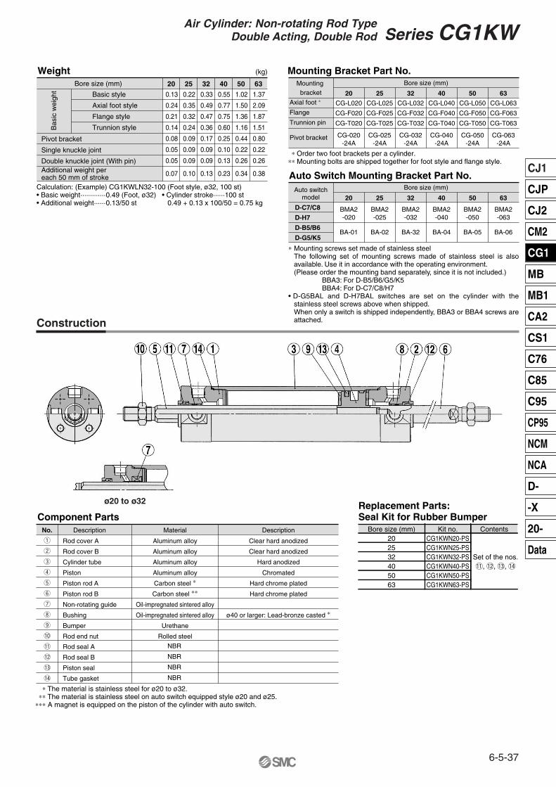
Weight (kg)
Bore size (mm) Mounting bracket
Auto switchmodel
Bore size (mm)20
Basic style
Axial foot style
Flange style
Trunnion style
Axial foot ∗
Flange
Trunnion pin
D-C7/C8
D-H7
D-B5/B6
D-G5/K5
Pivot bracket
CG-L020
CG-F020
CG-T020
CG-020-24A
20
CG-L025
CG-F025
CG-T025
CG-025-24A
25
CG-L032
CG-F032
CG-T032
CG-032-24A
32
CG-L040
CG-F040
CG-T040
CG-040-24A
40
CG-L050
CG-F050
CG-T050
CG-050-24A
50
CG-L063
CG-F063
CG-T063
CG-063-24A
BMA2-020
BMA2-025
BMA2-032
BMA2-040
BMA2-050
BMA2-063
BA-01 BA-02 BA-32 BA-04 BA-05 BA-06
63
Bore size (mm)
20 25 32 40 50 63
0.13
0.24
0.21
0.14
0.08
0.05
0.05
0.07
25
0.22
0.35
0.32
0.24
0.09
0.09
0.09
0.10
32
0.33
0.49
0.47
0.36
0.17
0.09
0.09
0.13
40
0.55
0.77
0.75
0.60
0.25
0.10
0.13
0.23
50
1.02
1.50
1.36
1.16
0.44
0.22
0.26
0.34
63
1.37
2.09
1.87
1.51
0.80
0.22
0.26
0.38
Bas
ic w
eigh
t
Pivot bracket
Single knuckle joint
Double knuckle joint (With pin)
Mounting Bracket Part No.
Auto Switch Mounting Bracket Part No.
Component Parts
!1
!2
!3
!4
DescriptionNo. Material Description
∗ The material is stainless steel for ø20 to ø32. ∗∗ The material is stainless steel on auto switch equipped style ø20 and ø25.∗∗∗ A magnet is equipped on the piston of the cylinder with auto switch.
Rod cover A
Rod cover B
Cylinder tube
Piston
Piston rod A
Piston rod B
Non-rotating guide
Bushing
Bumper
Rod end nut
Aluminum alloy
Aluminum alloy
Aluminum alloy
Aluminum alloy
Carbon steel ∗
Carbon steel ∗∗
Oil-impregnated sintered alloy
Oil-impregnated sintered alloy
Urethane
Rolled steel
Clear hard anodized
Clear hard anodized
Hard anodized
Chromated
Hard chrome plated
Hard chrome plated
ø40 or larger: Lead-bronze casted ∗
q
w
e
r
t
y
u
i
o
!0
Rod seal A
Rod seal B
Piston seal
Tube gasket
NBR
NBR
NBR
NBR
Bore size (mm)202532405063
Kit no.CG1KWN20-PSCG1KWN25-PSCG1KWN32-PSCG1KWN40-PSCG1KWN50-PSCG1KWN63-PS
Contents
Set of the nos.!1, !2, !3, !4
Replacement Parts:Seal Kit for Rubber Bumper
Construction
∗ Order two foot brackets per a cylinder. ∗∗ Mounting bolts are shipped together for foot style and flange style.
∗ Mounting screws set made of stainless steelThe following set of mounting screws made of stainless steel is also available. Use it in accordance with the operating environment. (Please order the mounting band separately, since it is not included.)
BBA3: For D-B5/B6/G5/K5BBA4: For D-C7/C8/H7
• D-G5BAL and D-H7BAL switches are set on the cylinder with the stainless steel screws above when shipped. When only a switch is shipped independently, BBA3 or BBA4 screws are attached.
ø20 to ø32
Calculation: (Example) CG1KWLN32-100 (Foot style, ø32, 100 st)• Basic weight·············0.49 (Foot, ø32) • Cylinder stroke······100 st• Additional weight······0.13/50 st 0.49 + 0.13 x 100/50 = 0.75 kg
Additional weight pereach 50 mm of stroke
6-5-37
Series CG1KWAir Cylinder: Non-rotating Rod TypeDouble Acting, Double Rod
CJ1
CJP
CJ2
CM2
CG1
MB
MB1
CA2
CS1
C76
C85
C95
CP95
NCM
NCA
D-
-X
20-
Data

Precautions
ø ø
ø
ø ø
Bore size(mm)
Stroke range (mm) A AL C D DK E F GA I
Up to 200
Up to 300
Up to 300
Up to 500
Up to 600
Up to 600
18
22
22
30
35
35
15.5
19.5
19.5
27
32
32
B1
13
17
17
19
27
27
14
16.5
20
26
32
38
8
10
12
16
20
20
9.2
11
12
16
20
20
12
14
18
25
30
32
2
2
2
2
2
2
12
12
12
13
14
14
H1
5
6
6
8
11
11
J
26
31
38
47
58
72
K
M4 x 0.7 depth 7
M5 x 0.8 depth 7.5
M5 x 0.8 depth 8
M6 x 1 depth 12
M8 x 1.25 depth 16
M10 x 1.5 depth 16
5
5.5
5.5
6
7
7
6
8
10
14
18
18
8
10
10
14
18
18
M8 x 1.25
M10 x 1.25
M10 x 1.25
M14 x 1.5
M18 x 1.5
M18 x 1.5
24
29
35.5
44
55
69
1/8
1/8
1/8
1/8
1/4
1/4
77
77
79
87
102
102
Allowable rotational torque(N·m or less)
20
25
32
40
50
63
ø20
0.2
ø25, ø32
0.25
ø40, ø50, ø63
0.44
Caution on Handling/Disassembly
Caution
Bore size(mm)
H
35
40
40
50
58
58
11
11
11
12
13
13
ZZ
147
157
159
187
218
218
20
25
32
40
50
63
TC
M5 x 0.8
M6 x 0.75
M8 x 1.0
M10 x 1.25
M12 x 1.25
M14 x 1.5
TA
KA KB MM NA P S
Basic Style with Rubber Bumper: CG1KWBN
Note) Dimensions are the same as CG1W standard type. Refer to page 6-5-20.
• Old number is CG1�N�-�-XC21 as made-to-order.
1. Avoid using the air cylinder in such a way that rotational torque would be applied to the piston rod.• If rotational torque is applied, the non-rotating guide will
become deformed, thus affecting the non-rotating accuracy. Refer to the table below for the approximate values of the allowable range of rotational torque.
• To screw a bracket or a nut onto the piston rod, make sure to retract the piston rod entirely, and place a wrench over the flat portion of the rod that protrudes.
Tighten it by giving consideration to prevent the tightening torque from being applied to the non-rotating guide.
2.When replacing rod seals, please contact SMC.Air leakage may be happened, depending on the position in which a rod seal is fitted. Thus, please contact SMC when replacing them.
Width across flats B1
S + Stroke
ZZ + 2 stroke
Width across flats KA
H + Stroke
Be sure to read before handling. Refer to pages 6-20-3 to 6-20-6 for Safety Instructions and Actuator Precautions.
Series CG1KW
6-5-38

Bore size(mm)
Bore size(mm)
D-C7, D-C8 A30303135.54343
B28.528.529.532.540.540.5
Hs24.52730.53540.547.5
A30303135.54343
B28.528.529.532.540.540.5
B22.522.523.526.534.534.5
B25.525.526.529.537.537.5
Hs2729.53337.54350
A Hs273033.53843.550.5
A27272832.54040
Hs27.53033.53843.550.5
202532405063
D-C73C, D-C80C D-B5, D-B6 D-B59W
D-H7�D-H7�W
D-H7CD-H7BAL
A29293034.54242
Hs24.52730.53540.547.5
A27.527.528.53340.540.5
Hs24.52730.53540.547.5
B27.527.528.531.539.539.5
B27.527.528.531.539.539.5
B262627303838
A29293034.54242
Hs27.53033.53843.550.5
202532405063
D-H7NF D-H7C
Proper Auto Switch Mounting Position (Detection at stroke end) and Its Mounting Height
Without indicator light
Without indicator light—
20 to 63
Type Model Features Applicable bore size (mm)Electrical entry
D-C80D-C80CD-B53D-B64
Grommet Connector
Grommet
∗ Timer equippede type, solid state auto switch (D-G5NTL) is also available.∗ Wide range detection type, solid state auto switch (D-G5NBL) is also available.∗ With pre-wide connector is available for D-G5NTL and D-G5NBL.
Reed switch
D-H7C
D-G5NBLD-G5NTL
Auto switch model
Operating Range
D-B59W
20D-C7�/C80/C73C/C80CD-B5�/B64
D-H7NF, D-H7�/H7�W/H7BAL
Bore size (mm)50 6325 32 40
D-H7�/H7�W/H7NF/H7BAL
D-C7/C8
D-H7CG5NTL
D-B5/B6
D-C73C
∗ Since this is a guideline including hysteresis, not meant to be guaranteed. (Assuming approximately ±30% dispersion)There may be the case it will vary substantially depending on an ambient environment.
Auto switchHs~= Hs~=
Hs~=Hs~=
Auto switch
Auto switch
Hs~= Auto switch
Auto switch
Hs~= Auto switch
11
176.5
10.56.5
45
10
1469.56
45
10
145
105
45
9
144.594.5
40
10
1348.5 4
40
8
13474
35
24242529.53737
Other than the applicable auto switches listed in “How to Order”, the following auto switches can be mounted. For detailed specifications, refer to page 6-16-1.
6-5-39
Series CG1KWAir Cylinder: Non-rotating Rod TypeDouble Acting, Double Rod
CJ1
CJP
CJ2
CM2
CG1
MB
MB1
CA2
CS1
C76
C85
C95
CP95
NCM
NCA
D-
-X
20-
Data

CG1R
CDG1R
N
N
25
25
Built-in magnetAuto switch
100
100 H7BW
Bore size202532405063
20 mm25 mm32 mm40 mm50 mm63 mm
NilSn
Nil2 pcs.1 pc.
“n” pcs.
Without auto switch(Built-in magnet)Cushion
NA
Non-lube/Rubber bumperNon-lube/Air cushion
Special functionType Electricalentry
Grommet
Grommet
Grommet
Grommet
Indic
ator
light
Wiring(Output)
2-wire
3-wire (NPNequivalent)
Load voltage
—
ACDC
Auto switch model
C76
B54C73
C73C
B59W
H7A1H7A2H7BH7C
H7NWH7PWH7BW
H7BA
H7NF
Lead wire length (m) ∗
0.5(Nil)
3(L)
5(Z)
�
�
�
�
�
�
�
�
�
�
�
�
—
�
�
�
�
�
�
�
�
�
�
�
�
�
�
�
—
�
�
�
—
�
�
�
�
�
�
�
�
�
ICcircuit
Relay,PLC
Applicable load
Applicable Auto Switch/Refer to page 6-16-1 for further information on auto switches.
• Since there are other applicable auto switches than listed, refer to page 6-5-45 for details.• For details about auto switches with pre-wire connector, refer to page 6-16-60.
20 to 63
—
5 V
100 V, 200 V
100 V
—
12 V
—
5 V, 12 V
12 V
5 V, 12 V
12V
5 V, 12 V
—
—
24 VConnector
Connector
Diagnostic indication(2-color indication)
With diagnostic output(2-color indication)
Water resistant(2-color indication)
Diagnostic indication(2-color indication)
—
—
Yes
Yes
2-wire
3-wire (NPN) 3-wire (PNP)
2-wire
3-wire (NPN) 3-wire (PNP)
4-wire (NPN)
24 V
ICcircuit
—
ICcircuit
—
ICcircuit
Relay, PLC
Applicable bore size (mm)
Ree
d sw
itch
Sol
id s
tate
sw
itch
None(N)
Pre-wireconnector
—
——�
—
———�
———
—
—
—
———
—
�
�
�
—�
�
�
�
�
∗ Solid state switches marked with “�” are produced upon receipt of order.
—
How to Order
∗ For the applicable auto switch model, refer to the table below.
∗ Lead wire length symbols: 0.5 m ·········· Nil (Example) C73C 3 m ·········· L (Example) C73CL5 m ·········· Z (Example) C73CZ
None ·········· N (Example) C73CN
Air Cylinder: Direct Mount TypeDouble Acting, Single Rod
Series CG1Rø20, ø25, ø32, ø40, ø50, ø63
Cylinder stroke (mm)
Number ofauto switches
With auto switch
Without auto switch
Refer to “Standard Stroke” on page 6-16-41.
6-5-40

Series CG1R direct mount cylinder can be installed directly through the use of a square rod cover.Space-saving has been realized.Because it is a directly mounted style without using brackets, its overall length is shorter, and its installation pitch can be made smaller. Thus, the space that is required for installation has been dramatically reduced.
AccessoryMounting
Standard StrokeStandard stroke ∗
(mm)Bore size
(mm)Basic style
�
�
�
20
25, 32
40, 50, 63
25, 50, 75, 100, 125, 150
25, 50, 75, 100, 125, 150, 200
25, 50, 75, 100, 125, 150,
200, 250, 300
Standardequipment
Option
Rod end nut
Single knuckle joint
Double knuckle joint ∗(With pin)
WeightBore size (mm) 20
Auto Switch Mounting Bracket Part No.Auto switch
modelBore size (mm)
20
D-C7/C8D-H7D-B5/B6D-G5
BMA2-020
BA-01
25
BMA2-025
BA-02
32
BMA2-032
BA-32
40
BMA2-040
BA-04
50
BMA2-050
BA-05
63
BMA2-063
BA-06
0.140.050.050.050.01
25
0.230.090.090.070.01
32
0.350.090.090.090.02
40
0.570.100.130.150.02
50
1.040.220.260.220.03
63
1.490.220.260.260.03
Basic weight
Single knuckle joint
Double knuckle joint (With pin)
Additional weight per each 50 mm of stroke
Additional weight with air cushion
Calculation: (Example) CG1RN32-100(ø32, 100 st)
• Basic weight························· 0.35• Additional weight·················· 0.09/50 st • Cylinder stroke······················100 st 0.35 + 0.09 x 100/50 = 0.53 kg
(kg)
Specifications
Action
Type
Fluid
Proof pressure
Maximum operating pressure
Minimum operating pressure
Ambient and fluid temperature
Piston speed
Thread tolerance
Stroke length tolerance
Cushion
Double acting, Single rod
Non-lube
Air
1.5 MPa
1.0 MPa
0.05 MPa
Without auto switch: –10 to 70°C (No freezing)
With auto switch: –10 to 60°C (No freezing)
50 to 1000 mm/s
JIS Class 2
Up to 300 mm
Rubber bumper, Air cushion
20 25 32 40 50 63
st +1.4 0
JIS Symbol
-XA�
-XB6
-XB7
-XB9
-XB13
-XC6
-XC8
-XC9
-XC13
-XC20
-XC22
Change of rod end shape
Heat resistant cylinder (150°C)
Cold resistant cylinder
Low speed cylinder (10 to 50 mm/s)
Low speed cylinder (5 to 50 mm/s)
Piston rod and rod end nut made of stainless steel
Adjustable stroke cylinder/Adjustable extension type
Adjustable stroke cylinder/Adjustable retraction type
Auto switch rail mounting
Head cover axial port
Fluoro rubber seals
Symbol Specifications
Made to Order Specifications(For details, refer to page 6-17-1.)
∗ Pin and snap ring are shipped together with double knuckle joint. ∗ Other intermediate strokes can be
manufactured upon receipt of order. Long strokes are not available.Spacers are not used for intermediate strokes.
∗ Mounting screws set made of stainless steelThe following set of mounting screws made of stainless steel is also available. Use it in accordance with the operating environment. (Please order the mounting band separately, since it is not included.)
BBA3: For D-B5/B6/G5BBA4: For D-C7/C8/H7
• D-G5BAL and D-H7BAL switches are set on the cylinder with the stainless steel screws above when shipped. When a switch only is shipped, BBA3 or BBA4 screws are attached.
Bore size (mm)
6-5-41
Series CG1RAir Cylinder: Direct Mount TypeDouble Acting, Single Rod
CJ1
CJP
CJ2
CM2
CG1
MB
MB1
CA2
CS1
C76
C85
C95
CP95
NCM
NCA
D-
-X
20-
Data

Specifications20, 25, 32, 40, 50, 63
Double acting
Air
1.0 MPa
0.05 MPa
Rubber bumper
50 to 400 mm/s
M5 x 0.8
Action
Fluid
Maximum operating pressure
Minimum operating pressure
Cushion
Piston speed
Relief port size
Action
Fluid
Maximum operating pressure
Minimum operating pressure
Relief port size
∗ Auto switch can be mounted.
Specifications
Clean Series Copper-free
20, 25, 32, 40, 50, 63
Double acting
Air
1.0 MPa
0.05 MPa
With rubber bumper
With air cushion
50 to 1000 mm/s
Type N
Type ACushion
10-CG1RN Bore size Stroke 20-CG1R Bore size StrokeType
For detailes, refer to the separate catalog, “Pneumatic Clean Series”.
Clean Series (With relief port)The rod portion of the actuator has a double seal construction, and a relief port is provided to discharge the exhaust air directly outside of the clean room.Thus, it can be used in a Class 100 clean room.
This cylinder eliminates any influences of copper ions or fluororesins on color CRTs. Copper materials have been nickel plated or replaced with non-copper materials to prevent the generation of copper ions.
Copper-free
Bore size (mm) Bore size (mm)
Series CG1R
6-5-42

Component PartsMaterialNo. NoteDescription
Rod cover
Tube cover
Piston
Piston rod
Bushing
Bumper A
Bumper B
Snap ring
Wear ring
Rod end nut
Piston gasket
Aluminum alloy
Aluminum alloy
Aluminum alloy
Carbon steel ∗Oil-impregnated
sintered alloy
Urethane
Urethane
Stainless steel
Resin
Rolled steel
NBR
Clear hard anodized
Clear hard anodized
Chromated
Hard chrome plated
ø40 or larger: Lead-bronze casted
ø40 or larger: The same as bumper A
Nickel plated
q
w
e
r
t
y
u
i
o
!0
!1
Cushion ring A
Cushion ring B
Brass
Brass ø32 or larger: The same as A
!2
!3
MaterialNo. Note
@2
@3
@4
NBR
NBR
NBR
NBR
NBR
Rod seal
Piston seal
Tube gasket
Description
@5
@6
Valve seal
Valve retaining gasket
Seal retainer
Cushion valve
Valve retainer
Lock nut
Cushion seal A
Cushion seal B
Cushion ring gasket A
Cushion ring gasket B
Rolled steel
Rolled steel
Rolled steel
Carbon steel
Urethane
Urethane
NBR
NBR
Electroless nickel plated
Electroless nickel plated
Nickel plated
ø32 or larger: The same as A
!4
!5
!6
!7
!8
!9
@0
@1
Basic style: Bottom mounting style/with rubber bumper
With air cushion
Construction
Note) In the case of cylinders with auto switches, rubber magnets are installed in the piston.
∗ The material is stainless steel on auto switch equipped styles ø20 and ø25.
Replacement parts/Seal kit are the same as standard type, double acting, single rod. Refer to page 6-5-7.
6-5-43
Series CG1RAir Cylinder: Direct Mount TypeDouble Acting, Single Rod
CJ1
CJP
CJ2
CM2
CG1
MB
MB1
CA2
CS1
C76
C85
C95
CP95
NCM
NCA
D-
-X
20-
Data

Bore size(mm)
Stroke range(mm)
202532405063
A AL B1 D E
182222303535
15.519.519.5273232
131717192727
81012162020
121418253032
Up to 150Up to 200Up to 200Up to 300Up to 300Up to 300
GA GB H H1 I
202226303339
F
222222
101010101212
273232394545
5668
1111
263138475872
K KA L
55.55.5677
68
10141818
30.436.442.452.464.576.6
N P S X Y
272933374450
1/81/81/81/81/41/4
75778394
108114
384445556264
111213161719
LH LX
151821263238
LD
ø5.5, ø9.5 counterbore depth 6
ø6.6, ø11 counterbore depth 7
ø9, ø14 counterbore depth 9
ø11, ø17.5 counterbore depth 12
ø14, ø20 counterbore depth 14
ø18, ø26 counterbore depth 18
182224324146
ZZ
104111117135155161
MM
M8 x 1.25M10 x 1.25M10 x 1.25M14 x 1.5M18 x 1.5M18 x 1.5
With Air CushionBore size
(mm)Stroke range
(mm)
202532405063
P WA
M5 x 0.8M5 x 0.8Rc 1/8Rc 1/8Rc 1/4Rc 1/4
222428323642
Up to 150Up to 200Up to 200Up to 300Up to 300Up to 300
WB
151515151717
WC
8.51114.518.52229
WD
22————
WH
2527.530.535.543.549.5
WH2
232528.53340.547.5
Wθ
30°30°25°20°20°20°
With air cushion: CG1RA
With rubber bumper: CG1RN
ø
ø
ø
ø
ø
ø
ø
ø
Basic Style with Bottom Mounting
Width acrossflats B1
Width acrossflats B1
2-Rc P
S + StrokeZZ + Stroke
S + StrokeZZ + Stroke
A port
A port
Series CG1R
6-5-44

D-B5
D-H7
D-C7 D-G5, D-K5
D-C73C
D-H7C
A B
20
25
32
40
50
63
Proper Auto Switch Mounting Position Auto Switch Mounting Height
Applicablebore size (mm)
Autoswitchmodel D-C7/C8
D-C73C/C80C
9
9
10
14.5
17
17
20.5
20.5
21.5
23.5
28.5
28.5
A B
D-B5/B6
3
3
4
8.5
11
11
15.5
15.5
15.5
19
22.5
22.5
A B
D-B59W
6
6
7
11.5
14
14
17.5
17.5
18.5
20.5
25.5
25.5
A B
D-H7�WD-H7NFD-H7BALD-H7�D-H7C
8
8
9
13.5
16
16
19.5
19.5
20.5
22.5
27.5
27.5
A B
D-G5NTL
4.5
4.5
5.5
10
12.5
12.5
16
16
17
19
24
24
HS
D-B5/B6D-B59WD-G5NTLD-H7C
27.5
30
33.5
38
43.5
50.5
HS
D-C73CD-C80C
27
29.5
33
37.5
43
50
HS
D-C7/C8D-H7�D-H7�WD-H7�FD-H7BAL
24.5
27
30.5
35
40.5
47.5
Type Model Features
Without indicator light
—Without indicator light
Applicable bore size (mm)
20 to 63
Electrical entryD-C80D-C80CD-B53D-B64
GrommetConnector
GrommetReed switch
Operating Range
Auto switch modelBore size (mm)
20 25 32 40 50 63
D-B59WD-H7NF/D-H7�/H7�W/H7BAL
D-C7�/C80/C73C/C80CD-B5�/B64
D-H7C
D-G5NBLD-G5NTL
Proper Auto Switch Mounting Position (Detection at stroke end) and Its Mounting Height
∗ Since this is a guideline including hysteresis, not meant to be guaranteed. (Assuming approximately ±30% dispersion)There may be the case it will vary substantially depending on an ambient environment.
∗ Timer equipped type, solid state auto switch (D-G5NTL) is also available.∗ Wide range detection type, solid state auto switch (D-G5NBL) is also available.∗ With pre-wire connector is available for D-G5NTL and D-G5NBL.
Other than the applicable auto switches listed in “How to Order”, the following auto switches can be mounted. For detailed specifications, refer to page 6-16-1.
=~Hs =~Hs
=~Hs
=~Hs
=~Hs
=~Hs
11
176.5
10.56.5
45
10
1469.5
645
10
145
105
45
8
13474
35
10
1348.54
40
9
144.59
4.540
6-5-45
Series CG1RAir Cylinder: Direct Mount TypeDouble Acting, Single Rod
CJ1
CJP
CJ2
CM2
CG1
MB
MB1
CA2
CS1
C76
C85
C95
CP95
NCM
NCA
D-
-X
20-
Data

CG1KRN 25 100
CDG1KRN 25 100 H7BW
Built-in magnet
Non-rotating rod type
Mounting styleN Non-lube/Rubber bumper
Bore size202532405063
20 mm25 mm32 mm40 mm50 mm63 mm
Cylinder stroke (mm)
Number ofauto switches
NilSn
2 pcs.1 pc.
“n” pcs.
Auto switch
Nil Without auto switch(Built-in magnet)
TypeElectrical
entry
Grommet
Grommet
Grommet
Grommet
Indic
ator
light
Wiring(Output)
2-wire
3-wire (NPNequivalent)
Load voltage
—
ACDC
Auto switch model
C76
B54C73
C73C
B59W
H7A1H7A2H7BH7C
H7NWH7PWH7BW
H7BA
H7NF
Lead wire length (m) ∗
0.5(Nil)
3(L)
5(Z)
�
�
�
�
�
�
�
�
�
�
�
�
—
�
�
�
�
�
�
�
�
�
�
�
�
�
�
�
—
�
�
�
—
�
�
�
�
�
�
�
�
�
ICcircuit
Applicable load
Applicable Auto Switch/Refer to page 6-16-1 for further information on auto switches.
• Since there are other applicable auto switches than listed, refer to page 6-5-51 for details.• For details about auto switches with pre-wire connector, refer to page 6-16-60.
20 to 63
—
5 V
100 V, 200 V
100 V
—
12 V
—
5 V, 12 V
12 V
5 V, 12 V
12 V
5 V, 12 V
—
—
24 V
Yes
Yes
Connector
Connector
Special function
Diagnostic indication(2-color indication)
With diagnostic output(2-color indication)
Water resistant(2-color indication)
Diagnostic indication(2-color indication)
—
—
2-wire
3-wire (NPN) 3-wire (PNP)
2-wire
3-wire (NPN) 3-wire (PNP)
4-wire (NPN)
24 V
ICcircuit
—
ICcircuit
—
ICcircuit
Applicable bore size (mm)
Ree
d sw
itch
Sol
id s
tate
sw
itch
None(N)
Pre-wireconnector
—
——�
—
———�
———
—
—
—
———
—
�
�
�
—�
�
�
�
�
∗ Solid state switches marked with “�” are produced upon receipt of order.
Relay,PLC
Relay, PLC
—
How to Order
Refer to “Standard Stroke” on page 6-5-47.
∗ For the applicable auto switch model, refer to the table below.
∗ Lead wire length symbols: 0.5 m ·········· Nil (Example) C73C 3 m ·········· L (Example) C73CL5 m ·········· Z (Example) C73CZ
None ·········· N (Example) C73CN
Air Cylinder: Direct Mount, Non-rotating RodDouble Acting, Single Rod
Series CG1KRø20, ø25, ø32, ø40, ø50, ø63
With auto switch
Without auto switch
Note) Air cushion type “CG1KRA” is a made-to-order product.
6-5-46

Basic weight
Single knuckle joint
Double knuckle (With pin)
Additional weight per each 50 mm of strokeCalculation: (Example) CG1KRN32-100
(ø32, 100 st)• Basic weight····················0.35• Additional weight····················0.09/50 st• Cylinder stroke······100 st0.35 + 0.09 x 100/50 = 0.53 kg
Weight (kg)
Bore size (mm)
1.48
0.22
0.26
0.26
631.04
0.22
0.26
0.22
500.56
0.10
0.13
0.15
400.35
0.09
0.09
0.09
320.24
0.09
0.09
0.07
25
0.14
0.05
0.05
0.05
20
Standard StrokeBore size
(mm) Standard stroke (mm) ∗
25, 50, 75, 100, 125, 15025, 50, 75, 100, 125, 150, 20025, 50, 75, 100, 125, 150, 200, 250, 300
2025, 32
40, 50, 63
Standardequipment
Option
Rod end nut
Single knuckle joint
Double knuckle joint ∗(With pin)
�
�
�
AccessoryMounting Basic style
Allowable rotational torque(N·m or less)
ø200.2
ø25, ø320.25
ø40, ø50, ø630.44
Caution on Handling/Disassembly
Caution
Specifications
Action
Type
Fluid
Proof pressure
Maximum operating pressure
Minimum operating pressure
Ambient and fluid temperature
Piston speed
Thread tolerance
Stroke length tolerance
Cushion
Rod non-rotating accuracy
Double acting, Single rod
Non-lube
Air
1.5 MPa
1.0 MPa
0.05 MPa
Without auto switch: –10 to 70°C (No freezing)
With auto switch: –10 to 60°C (No freezing)
50 to 500 mm/s
JIS Class 2
Up to 300 mm
Rubber bumper
20 25 32 40 50
±1° ±0.8° ±0.5°
63
st +1.4 0
Auto Switch Mounting Bracket Part No.Auto switch
model
D-C7/C8D-H7D-B5/B6D-G5
Bore size (mm)
BMA2-020
BA-01
20
BMA2-025
BA-02
25
BMA2-032
BA-32
32
BMA2-040
BA-04
40
BMA2-050
BA-05
50
BMA2-063
BA-06
63
Series CG1KR direct mount, non-rotating rod type cylinder can be installed directly through the use of a square rod cover.
Space-saving has been realized.Because it is a directly mounted style without using brackets, its overall length is shorter, and its installation pitch can be made smaller. Thus, the space that is required for installation has been dramatically reduced.
JIS Symbol
-XC8
-XC9
-XC20
Adjustable stroke cylinder/Adjustable extension type
Adjustable stroke cylinder/Adjustable retraction type
Head cover axial port
Symbol Specifications
Made to Order Specifications(For details, refer to page 6-17-1.)
∗ Other intermediate strokes can be manufactured upon receipt of order. Long strokes are not available.Spacers are not used for intermediate strokes.
∗ Pin and snap ring are shipped together with double knuckle joint.
∗ Mounting screws set made of stainless steelThe following set of mounting screws made of stainless steel is also available. Use it in accordance with the operating environment. (Please order the mounting band separately, since it is not included.)
BBA3: For D-B5/B6/G5BBA4: For D-C7/C8/H7
• D-G5BAL and D-H7BAL switches are set on the cylinder with the stainless steel screws above when shipped.When only a switch is shipped independently, BBA3 or BBA4 screws are attached.
1.Avoid using the air cylinder in such a way that rotational torque would be applied to the piston rod.
� To screw a bracket or a nut onto the piston rod, make sure to retract the piston rod entirely, and place a wrench over the flat portion of the rod that protrudes.
Tighten it by giving consideration to prevent the tightening torque from being applied to the non-rotating guide.
2. When replacing rod seals, please contact SMC.Air leakage may be happened, depending on the position in which a rod seal is fitted. Thus, please contact SMC when replacing them.
Bore size (mm)
� If rotational torque is applied, the non-rotating guide will become deformed, thus affecting the non-rotating accuracy. Refer to the table below for the allowable range of the allowable range of rotational torque.
6-5-47
Series CG1KRAir Cylinder: Direct Mount, Non-rotating Rod TypeDouble Acting, Single Rod
CJ1
CJP
CJ2
CM2
CG1
MB
MB1
CA2
CS1
C76
C85
C95
CP95
NCM
NCA
D-
-X
20-
Data

Non-rotating rod type/Bottom mounting style
ø
ø
ø
ø
Component PartsNo.
Rod cover
Tube cover
Piston
Piston rod
Non-rotating guide
Bushing
Rod end nut
Bumper
Wear ring
Aluminum alloy
Aluminum alloy
Aluminum alloy
Carbon steel ∗
Oil-impregnated sintered alloy
Oil-impregnated sintered alloy
Rolled steel
Urethane
Resin
Clear hard anodized
Clear hard anodized
Chromated
Hard chrome plated
ø20 to ø32 only
Nickel plated
!0
!1
!2
Rod seal
Piston seal
Tube gasket
NBR
NBR
NBR
Descriptionq
w
e
r
t
y
u
i
o
Material Note
Auto switch mounting position is the same as that on page 6-5-45.
Bore size(mm)
202532405063
Stroke range(mm)
Up to 150Up to 200Up to 200Up to 300Up to 300Up to 300
A
182222303535
AL
15.519.519.5273232
B1
131717192727
D
9.21112162020
E
121418253032
GA
202226303339
GB
101010101212
H
273232394545
H1
5668
1111
I
263138475872
KA
81010141818
L
30.436.442.452.464.576.6
LD
ø5.5, ø9.5 counterbore depth 6ø6.6, ø11 counterbore depth 7ø9, ø14 counterbore depth 9
ø11, ø17.5 counterbore depth 12ø14, ø20 counterbore depth 14ø18, ø26 counterbore depth 18
LH
151821263238
LX
182224324146
MM
M8 x 1.25M10 x 1.25M10 x 1.25
M14 x 1.5M18 x 1.5M18 x 1.5
N
272933374450
P
1/81/81/81/81/41/4
S
75778394
108114
X
384445556264
Y
111213161719
ZZ
104111117135155161
Construction
Basic Style with Bottom Mounting: CG1KRN
ø20 to ø32
Replacement parts/Seal kits are the same as double acting, non-rotating rod type. Refer to page 6-5-33.
Width acrossflats B1
2-Rc P
S + StrokeZZ + Stroke
∗ The material is stainless steel for ø20, ø25 and ø32.
Series CG1KR
6-5-48
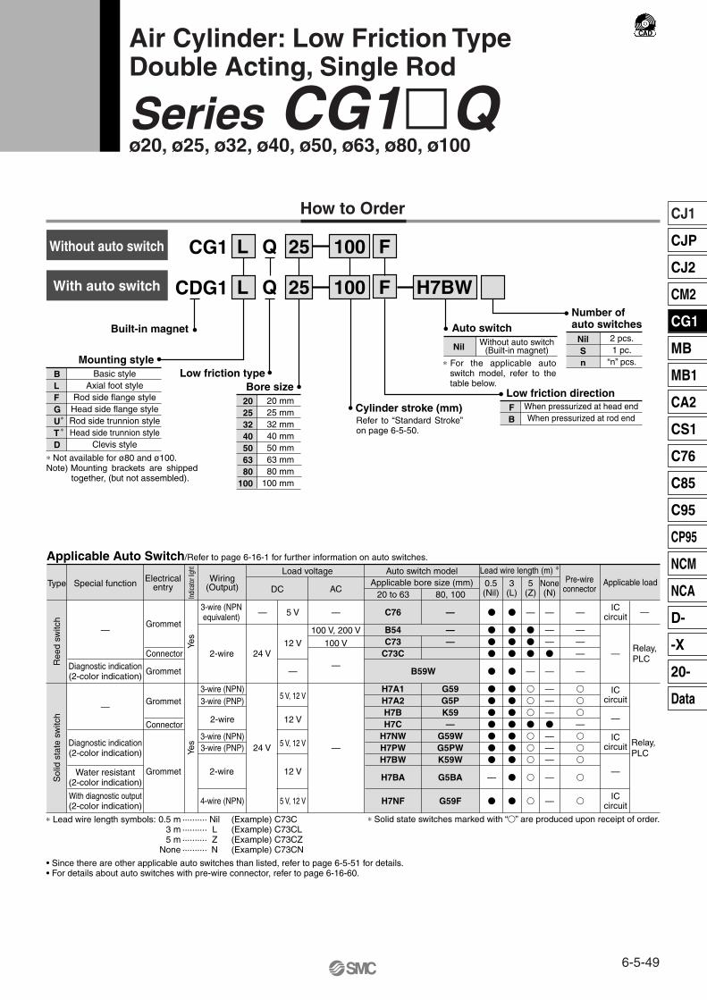
Built-in magnet
Low friction type
Auto switch
Mounting styleBasic style
Axial foot styleRod side flange styleHead side flange styleRod side trunnion styleHead side trunnion style
Clevis style
BLFGUTD
CG1 L 25 100 FQ
CDG1 L 25 100 F H7BWQ
Bore size20253240506380
100
20 mm25 mm32 mm40 mm50 mm63 mm80 mm
100 mm
Low friction directionWhen pressurized at head endWhen pressurized at rod end
FB
NilSn
Nil2 pcs.1 pc.
“n” pcs.
Without auto switch(Built-in magnet)
∗
∗
Type Electricalentry
Grommet
Grommet
Grommet
Grommet
Indic
ator
light
Wiring(Output)
2-wire
3-wire (NPNequivalent)
Load voltage
—
ACDC
Auto switch model
C76
B54C73
C73C
B59W
H7A1H7A2H7BH7C
H7NWH7PWH7BW
H7BA
H7NF
Lead wire length (m) ∗
0.5(Nil)
3(L)
5(Z)
�
�
�
�
�
�
�
�
�
�
�
�
—
�
�
�
�
�
�
�
�
�
�
�
�
�
�
�
—
�
�
�
—
�
�
�
�
�
�
�
�
�
ICcircuit
Applicable load
Applicable Auto Switch/Refer to page 6-16-1 for further information on auto switches.
• Since there are other applicable auto switches than listed, refer to page 6-5-51 for details.• For details about auto switches with pre-wire connector, refer to page 6-16-60.
20 to 63
—
——
G59G5PK59—
G59WG5PWK59W
G5BA
G59F
80, 100
—
5 V
100 V, 200 V
100 V
—
12 V
—
5 V, 12 V
12 V
5 V, 12 V
12 V
5 V, 12 V
—
—
24 V
Yes
Yes
Connector
Connector
Special function
Diagnostic indication(2-color indication)
With diagnostic output(2-color indication)
Water resistant(2-color indication)
Diagnostic indication(2-color indication)
—
—
2-wire
3-wire (NPN)3-wire (PNP)
2-wire
3-wire (NPN)3-wire (PNP)
4-wire (NPN)
24 V
ICcircuit
—
ICcircuit
—
ICcircuit
Applicable bore size (mm)
Ree
d sw
itch
Sol
id s
tate
sw
itch
None(N)
Pre-wireconnector
—
——�
—
———�
———
—
—
—
———
—
�
�
�
—�
�
�
�
�
∗ Solid state switches marked with “�” are produced upon receipt of order.
Relay,PLC
Relay, PLC
—
How to Order
∗ Not available for ø80 and ø100.Note) Mounting brackets are shipped
together, (but not assembled).
∗ For the applicable auto switch model, refer to the table below.
∗ Lead wire length symbols: 0.5 m ·········· Nil (Example) C73C 3 m ·········· L (Example) C73CL5 m ·········· Z (Example) C73CZ
None ·········· N (Example) C73CN
Number ofauto switches
Cylinder stroke (mm)
Air Cylinder: Low Friction TypeDouble Acting, Single Rod
Series CG1�Qø20, ø25, ø32, ø40, ø50, ø63, ø80, ø100
With auto switch
Without auto switch
Refer to “Standard Stroke” on page 6-5-50.
6-5-49
CJ1
CJP
CJ2
CM2
CG1
MB
MB1
CA2
CS1
C76
C85
C95
CP95
NCM
NCA
D-
-X
20-
Data
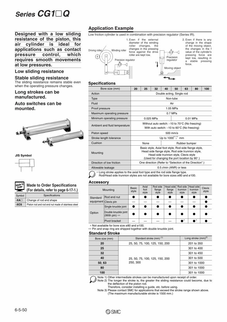
∗ Not available for bore size ø80 and ø100.∗∗ Pin and snap ring are shipped together with double knuckle joint.
Accessory
MountingBasicstyle
Clevis style
�
—
�
�
—
Axialfootstyle
�
—
�
�
—
Rod side flangestyle
Head sideflangestyle
�
—
�
�
—
�
—
�
�
—
�
—
�
�
�
�
—
�
�
�
�
�
�
�
�
Standardequipment
Standard StrokeBore size (mm)
20
25
32
40
50, 63
80
100
Standard stroke (mm) (1)
25, 50, 75, 100, 125, 150, 200
25, 50, 75, 100, 125, 150, 200250, 300
Long stroke (mm)(2)
201 to 350
301 to 400
301 to 450
301 to 500
301 to 1000
301 to 1000
301 to 1000
Rod end nut
Clevis pin
Single knuckle joint
Double knuckle joint(With pin) ∗∗
Pivot bracket
Option
Rod sidetrunnion
style
Head sidetrunnion
style
∗ ∗
SpecificationsBore size (mm)
Action
Type
Fluid
Proof pressure
Maximum operating pressure
Minimum operating pressure
Ambient and fluid temperature
Piston speed
Stroke length tolerance
Cushion
Mounting
Direction of low friction
Allowable leakage
Double acting, Single rod
Non-lube
Air
1.05 MPa
0.7 MPa
Without auto switch: –10 to 70°C (No freezing)
With auto switch: –10 to 60°C (No freezing)
500 mm/s
Up to 1000 mm
One direction (Refer to “Selection of the Direction”.)
0.5 l/min (ANR) or less
Basic style, Axial foot style, Rod side flange style, Head side flange style, Rod side trunnion style,
Head side trunnion style, Clevis style(Used for changing the port location by 90°.)
20 25 32 40 50 63 80 100
st +1.40
0.025 MPa 0.01 MPa
None Rubber bumper
Designed with a low sliding resistance of the piston, this air cylinder is ideal for applications such as contact pressure control, which requires smooth movements at low pressures.Low sliding resistanceStable sliding resistanceThe sliding resistance remains stable even when the operating pressure changes.
Long strokes can be manufactured.Auto switches can be mounted.
-XA�
-XC6
Change of rod end shape
Piston rod and rod end nut made of stainless steel
Symbol Specifications
Made to Order Specifications(For details, refer to page 6-17-1.)
Application Example
∗ Long stroke applies to the axial foot type and the rod side flange type.Rod/Head side trunnion styles are not available for bore sizes ø80 and ø100.
Note 1) Other intermediate strokes can be manufactured upon receipt of order. Note 2) The longer the stroke is, the greater the sliding resistance could become, due to
the deflection of the piston rod. Therefore, consider installing a guide, etc. before using.
Note 3) Please contact SMC for applications that exceed the stroke range shown above.(The maximum manufacturable stroke is 1500 mm.)
Low friction cylinder is used in combination with precision regulator (Series IR).
Driving roller Winding roller
Precision regulatorPrecision regulator
Moving object
Even if the external diameter of the winding roller changes, the changes in the pressing force against the drive roller are kept low.
Even if there is any change in the shape of the moving object, the changes in the f value of the cylinder’s pressing force are kept low, resulting in a stable pressing force.
JIS Symbol
1. 2.
Series CG1�Q
6-5-50

1. To use the air cylinder as a balancer, etc., pressurize it only from one of the ports as shown in the application example, and keep the other port open to the atmosphere.To operate by applying pressure from the rod cover port: Low friction direction B type (Application example (1))To operate by applying pressure from the head cover port:Low friction direction F type (Application example (2))In either case, if the piston rod is moved by an external force, it will operate with low friction for both in the extending and retracting directions.
2. When it is necessary to operate it as an ordinary double acting cylinder at an even lower operating speeds, use a low speed cylinder (refer to “Made to Order” on page 6-17-19).
2906 0.1 0.2 0.3 0.4 0.5 0.6 0.7
0.01
0.02
0.025
Operating pressure (MPa)
Slid
ing
resi
stan
ce ∗
(M
Pa)
∗ Conversion into the cylinder operating pressure.
ø25 ø20
ø32
ø50 ø40
ø63ø80ø100
WeightBore size (mm)
Bas
ic w
eigh
t Basic styleAxial foot styleFlange styleTrunnion styleClevis style
Pivot bracketSingle knuckle jointDouble knuckle joint (With pin)Additional weight per each 50 mm of stroke
200.110.220.190.120.160.080.050.050.05
250.180.310.280.200.260.090.090.090.07
320.280.440.420.310.430.170.090.090.09
400.440.660.640.490.670.250.100.130.15
500.831.311.170.971.230.440.220.260.22
631.171.891.671.311.850.800.220.260.26
802.233.192.94—
2.940.980.390.640.35
1003.435.184.78—
4.711.750.571.310.49
Calculation (Example) CG1LQ20-100B(Foot style, ø20, 100 st)
• Basic weight··············· 0.22 (Foot, ø20)• Additional weight········ 0.05/50 st
• Cylinder stroke············100 st • 0.22 + 0.05 x 100/50 = 0.32 kg
Mounting Bracket Part No.Mounting bracket
Axial foot ∗
Flange
Trunnion
Clevis
Pivot bracket ∗∗
Bore size (mm)
20CG-L020
CG-F020
CG-T020
CG-D020
CG-020-24A
25CG-L025
CG-F025
CG-T025
CG-D025
CG-025-24A
32CG-L032
CG-F032
CG-T032
CG-D032
CG-032-24A
40CG-L040
CG-F040
CG-T040
CG-D040
CG-040-24A
50CG-L050
CG-F050
CG-T050
CG-D050
CG-050-24A
63CG-L063
CG-F063
CG-T063
CG-D063
CG-063-24A
80CG-L080
CG-F080
—
CG-D080
CG-080-24A
100CG-L100
CG-F100
—
CG-D100
CG-100-24A
∗ Order two foot brackets per cylinder. ∗∗ Clevis pin, snap ring and mounting bolt are shipped for the clevis style. ∗∗∗ Mounting bolts are shipped together for foot style and flange style.
Auto Switch Mounting Bracket Part No.Auto switch
model
D-C7/C8D-H7D-B5/B6D-G5/K5
Bore size (mm)
20 25 32 40 50 63 80 100
BMA2-020
BA-01
BMA2-025
BA-02
BMA2-032
BA-32
BMA2-040
BA-04
BMA2-050
BA-05
BMA2-063
BA-06
—
BA-08
—
BA-10
1. In the direction of low friction operation, speed control must be effected through the meter-in system.With meter-out control, the exhaust pressure will increase and create a greater sliding resistance.
Auto switches can be mounted. Mounting position/height is the same as the double acting/single rod style. Refer to pages 6-5-13.
Type Model Features
Without indicator light
—Without indicator light
Applicable bore size (mm)
20 to 63
20 to 100
Electrical entry
D-C80D-C80CD-B53D-B64
Grommet Connector
Grommet
∗ Timer equipped type, solid state auto switch (D-G5NTL) is also available.∗ Wide range detection type, solid state auto switch (D-G5NBL) is also available.∗ With pre-wire connector is available for D-G5NTL and D-G5NBL.
Reed switch
Sliding Resistance of the Low Friction Side
Selecting the Low FrictionDirection
With Auto Switch
Operating Precautions
Warning
∗ Mounting screws set made of stainless steelThe following set of mounting screws made of stainless steel is also available. Use it in accordance with the operating environment. (Please order the mounting band separately, since it is not included.)
BBA3: For D-B5/B6/G5/K5BBA4: For D-C7/C8/H7
• D-G5BAL and D-H7BAL switches are set on the cylinder with the stainless steel screws above when shipped. When a switch only is shipped, BBA3 or BBA4 screws are attached.
∗ The material is stainless steel on auto switch equipped styles ø20 and ø25.
Other than the applicable auto switches listed in “How to Order”, the following auto switches can be mounted. For detailed specifications, refer to page 6-16-1.
6-5-51
Series CG1�QAir Cylinder: Low Friction Type
Double Acting, Single Rod
CJ1
CJP
CJ2
CM2
CG1
MB
MB1
CA2
CS1
C76
C85
C95
CP95
NCM
NCA
D-
-X
20-
Data

TA/TB cross section
ø ø
ø
ø
ø
Bore size(mm)
Stroke range(mm)
20253240506380
100
A AL B1 C D E F
1822223035354040
15.519.519.52732323737
1317171927273241
1416.5202632385060
Up to 350Up to 400Up to 450Up to 500Up to 1000Up to 1000Up to 1000Up to 1000
GA GB H H1 I
1214182530324050
22222233
1212121314142020
5668
11111316
3540405058587171
26313847587289
110
810121620202530
NA P S TA TB
24 29 35.5 44 55 69 80100
1/81/81/81/81/41/43/81/2
77777987
102102122122
111111121313——
111111121313——
K KA
5 5.5 5.5 6 7 71010
J
M4 x 0.7 depth 7M5 x 0.8 depth 7.5M5 x 0.8 Depth 8M6 x 1 depth 12
M8 x 1.25 depth 16M10 x 1.5 depth 16M10 x 1.5 depth 22M12 x 1.75 depth 22
68
101418182226
ZZ
114119121139162162196196
MM
M8 x 1.25M10 x 1.25M10 x 1.25M14 x 1.5M18 x 1.5M18 x 1.5M22 x 1.5M26 x 1.5
TA/TB Cross SectionBore size
(mm)
202532405063
5.5
6.5
7.5
8.5
10
14.5
TG
0.5
1
1
1.25
2
3
TFTE
M5 x 0.8
M6 x 0.75
M8 x 1.0
M10 x 1.25
M12 x 1.25
M14 x 1.5
TC∗
TDH9
81012141618
1212121314142020
Component PartsNo.
q
w
e
r
t
y
u
i
o
!0
!1
!2
!3
!4
!5
Description Material
Aluminum alloy
Aluminum alloy
Aluminum alloy
Aluminum alloy
Carbon steel ∗
Oil impregnated sintered alloy
NBR
NBR
NBR
Resin
NBR
Urethane
Stainless steel
Rolled steel
NBR
Note
Clear hard anodized
Clear hard anodized
Hard anodized
Chromated
Hard chrome plated
ø40 and larger are lead-bronze casted
Nickel plated
Rod cover
Head cover
Cylinder tube
Piston
Piston rod
Bushing
Rod seal
Piston seal
Tube gasket
Wear ring
Back up O-ring
Bumper
Snap ring
Rod end nut
Piston gasket
Bore size (mm) Kit no. CG1Q20-PSCG1Q25-PSCG1Q32-PSCG1Q40-PSCG1Q50-PSCG1Q63-PSCG1Q80-PSCG1Q100-PS
Contents
Set of the nos.u, i, o, !1
Replacement Parts: Seal Kit
Construction
Basic Style: CG1BQ
∗ Trunnion mounting taps with width across flats NA are not attached for bore sizes ø80 and ø100.
ø80, ø100
ø80, ø100
ø40 to ø100
20253240506380
100
Widthacross flats B1
S + StrokeZZ + Stroke
4
5
5.5
6
7.5
11.5
+0.080
+0.080
+0.080
+0.080
+0.080
+0.080
∗ Stainless steel is used as the material for ø20 and ø25 cylinder with auto switch.
∗ A magnet is equipped with the piston for cylinders with auto switch.
Series CG1�Q
6-5-52

Axial foot style: CG1LQ
Rod side flange style: CG1FQ
Head side flange style: CG1GQ
Head side trunnion style: CG1TQ
Rod side trunnion style: CG1UQ
B
34 38.5 45 54.5 70.5 82.5101121
LC
44445566
LD
6677
10121114
LH
2022253040455565
LS
5353536067677474
LT LX LZ M
33.53.545557
W
1010101017.517.52020
X
15151616.5222228.530
Y
7 7 8 8.511131416
Without rod bootZ
Without rod bootZZ
Axial Foot Style
20253240506380
100
Bore(mm)
Rod sideUp to 350Up to 400Up to 450Up to 500
Up to 1000Up to 1000Up to 1000Up to 1000
Stroke range Head side flangeZZ
Head sideUp to 200Up to 300Up to 300Up to 500Up to 600Up to 600Up to 750Up to 750
B E F FX FD FT HWithout rod boot
120126128147171171207210
Flange Style
20253240506380
100
Bore(mm)
Note) End boss is machined on the flange for øE.∗ Other dimensions are the same as basic style.
Rod sideUp to 200Up to 300Up to 300Up to 500Up to 600Up to 600
Stroke range
TW
424248566474
TX
162022303646
TY
282828303646
TZ
47.6 53 67.7 78.7 98.6119.2
Without rod boot465151627171
ZRod side
ZHead side
ZZWithout rod boot
101106108125147147
Without rod boot122127132153179184
Head sideUp to 200Up to 300Up to 300Up to 500Up to 600Up to 600
3845.55463.57996
101010102020
5.5 5.5 6.6 6.6 911
253035405060
394354.565.58098
283340496074
3.23.24.54.568
(35.8)(39.8)(49.4)(58.4)(72.4)(90.4)
Trunnion Style
202532405063
Bore(mm)
202532405063
Bore(mm)
∗ Consists of pin, flat washer and hexagon socket head cap bolt. Note) For pivot bracket, refer to page 6-5-12.∗ Other dimensions are the same as basic style.
81012141618
–0.025–0.047
–0.025–0.047
–0.032–0.059
–0.032–0.059
–0.032–0.059
–0.032–0.059
∗ Other dimensions are the same as basic style.
With Mounting Bracket
47525363.575.575.59595
118123.5125.5144169.5169.5202.5206
404453617692
104128
1214182530324050
22222233
28323846587082
100
5.5 5.5 6.6 6.6 9111114
677899
1114
3540405058587171
B TDe8 TE TF TH TR TS TT TV
2-øTDø8(Pin O.D.) LS + Stroke
ZZ + Stroke
ZZ + Stroke
ZZ + Stroke
ZZ + Stroke
2-øT
Dø8
(Pin
O.D
.)
2-øT
Dø8
(Pin
O.D
.)
Bracketmounting
range
Bracketmounting
range
Z + Stroke
33334.54.54.56
323644546682
100120
4449587186
106125150
6-5-53
Series CG1�QAir Cylinder: Low Friction Type
Double Acting, Single Rod
CJ1
CJP
CJ2
CM2
CG1
MB
MB1
CA2
CS1
C76
C85
C95
CP95
NCM
NCA
D-
-X
20-
Data

B
(35.8)(39.8)(49.4)
(58.4)
(72.4)
(90.4)
110
130
424248
56
64
74
72
93
162022
30
36
46
85
100
282828
30
36
46
45
60
43.4 48 59.4
71.4
86
105.4
64
72
126133139
159
185
190
228
236
147154163
187
217
227
286.5
312.5
CD-G02CD-G25CD-G03
CD-G04
CD-G05
CD-G06
IY-G08
IY-G10
CD CX
——————2832
CZ
2933404960745664
L
1416202225303543
RR
1113151820221822
V
——————2632
TE
101010102020——
TF TH
2530354050605565
Clevis Style
20253240506380
100
Bore size(mm)
202532
40
50
63
80
100
Bore size(mm)
Applicable pin part no.
Stroke range(mm)
Clevis style: CG1DQ
(The above shows the case port location is changed by 90°.)
With Mounting Bracket
TT TV TW TX TY TZ Z ZZ
Z + StrokeZZ + Stroke
Z + StrokeZZ + Stroke
38 45.5 54 63.5 79 96 99.5120
810121416181822
5.5 5.5 6.6 6.6 9111113.5
3.2 3.2 4.5
4.5 6
8
11
12
Up to 200Up to 300Up to 300Up to 500Up to 600Up to 600Up to 750Up to 750
∗ Clevis pin and snap ring are shipped together with clevis type.
ø20 to ø63
ø80, ø100
øCD hole H10
Axis d9
øCD hole H10Axis d9
Note) ∗ For pivot bracket, refer to page 6-5-12.∗ Other dimensions are the same as basic style.
Series CG1�Q
6-5-54

CDBG1
L 25
L
N
N 25 H
H
N H7BW
N
Built-in magnet
20253240
506380
100
Bore size20 mm25 mm32 mm40 mm
50 mm63 mm80 mm
100 mm
Number ofauto switches
NilSn
2 pcs.1 pc.
“n” pcs.
Nil Without auto switch(Built-in magnet)
Auto switch
Cylinder stroke (mm)
CBG1
Basic styleAxial foot style
Rod side flange styleHead side flange styleRod side trunnion styleHead side trunnion style
Clevis style
Mounting styleBLFGUTD
100
100
Refer to “Standard Stroke” on page 6-5-56.
Lock positionHRW
Head end lockRod end lock
Double end lock
Manual release typeNL
Non-lock typeLock type
NilJK
With rod bootWithout rod bootNylon tarpaulin
Heat resistant tarpaulin
TypeNA
Rubber bumperAir cushion
∗
∗
∗ In the case of w/ rod boot, and a foot bracket or rod side flange as a bracket, those parts are to be assembled at the time of shipment.
Special functionType Electricalentry
Grommet
Grommet
Grommet
Grommet
Indic
ator
light
Wiring(Output)
2-wire
3-wire(NPN equivalent)
Load voltage
—
ACDC
Auto switch model
C76
B54C73
C73C
B59W
H7A1H7A2H7BH7C
H7NWH7PWH7BW
H7BA
H7NF
Lead wire length (m) ∗
0.5(Nil)
3(L)
5(Z)
�
�
�
�
�
�
�
�
�
�
�
�
—
�
�
�
�
�
�
�
�
�
�
�
�
�
�
�
—
�
�
�
—
�
�
�
�
�
�
�
�
�
ICcircuit
Relay,PLC
Applicable load
Applicable Auto Switch/Refer to page 6-16-1 for further information on auto switches.
• Since there are other applicable auto switches than listed, refer to page 6-5-64 for details.• For details about auto switches with pre-wire connector, refer to page 6-16-60.
20 to 63
—
——
G59G5PK59—
G59WG5PWK59W
G5BA
G59F
80, 100
—
5 V
100 V, 200 V
100 V
—
12 V
—
5 V, 12 V
12 V
5 V, 12 V
12 V
5 V, 12 V
—
—
24 V
Yes
Yes
Connector
Connector
Diagnostic indication(2-color indication)
With diagnostic output (2-color indication)
Water resistant (2-color indication)
Diagnostic indication(2-color indication)
—
—
2-wire
3-wire (NPN) 3-wire (PNP)
2-wire
3-wire (NPN) 3-wire (PNP)
4-wire (NPN)
24 V
ICcircuit
—
ICcircuit
ICcircuit
—
Relay, PLC
Applicable bore size (mm)
Ree
d sw
itch
Sol
id s
tate
sw
itch
None(N)
Pre-wireconnector
—
——�
—
———�
———
—
—
—
———
—
�
�
�
—�
�
�
�
�
∗ Solid state switches marked with “�” are produced upon receipt of order.
—
How to Order
∗ Not available for bore size ø80 and ø100.Besides, trunnion cannot be attached in the side to which an end lock is attached.
Note) Mounting brackets are shipped together, (but not assembled).
∗ For the applicable auto switch model, refer to the table below.
∗ Lead wire length symbols: 0.5 m ·········· Nil (Example) C73C 3 m ·········· L (Example) C73CL5 m ·········· Z (Example) C73CZ
None ·········· N (Example) C73CN
Air Cylinder: With End Lock
Series CBG1ø20, ø25, ø32, ø40, ø50, ø63, ø80, ø100
6-5-55
CJ1
CJP
CJ2
CM2
CG1
MB
MB1
CA2
CS1
C76
C85
C95
CP95
NCM
NCA
D-
-X
20-
Data

Rod Boot Material
Specifications
Lock Specifications
Up to 1500 mm
Up to 1000 mm
50 to 1000 mm/s
Up to 1000 mm, Up to 1200 mm
Standard Stroke
Action
Type
Fluid
Proof pressure
Maximum operating pressure
Minimum operating pressure
Ambient and fluid temperature
Piston speed
Stroke length tolerance
Thread tolerance
Cushion
Mounting ∗∗
Double acting, Single rod
Non-lube
Air
1.5 MPa
1.0 MPa
0.15 MPa ∗
Without auto switch: –10 to 70°C (No freezing)
With auto switch: –10 to 60°C (No freezing)
JIS Class 2
Rubber bumper, Air cushion
st +1.4 0
st +1.4 0st +1.8
0st +1.8 0
Lock position Head end, Rod end, Double end
2 mm or less
Non-lock type, Lock type
Holding force (Max.)(N)
Backlash
Manual release
ø20
215
ø25
330
ø32
550
ø40
860
ø50
1340
ø63
2140
ø80
3450
ø100
5390
Bore size(mm)
20
25
32
40
50, 63
80
100
Standard stroke (mm) (1)
25, 50, 75, 100, 125, 150, 200
25, 50, 75, 100, 125, 150, 200, 250, 300
Long stroke(mm)
Maximummanufacturable
stroke(mm)
201 to 350
301 to 400
301 to 450
301 to 800
301 to 1200
301 to 1400
301 to 1500
1500
Symbol
J
K
Rod boot material
Nylon tarpaulin
Heat resistant tarpaulin
Maximum operating temperature
70°C
110°C ∗
Model2
15 mm
20 mm
20 mm
1
10 mm
15 mm
10 mm
D-C7/C8D-B5/B6D-H7D-G5/K5
D-B59W
D-H7LF
No. of auto switches mounted
20 25 32 40 50 63 80 100
50 to 700 mm/s
Minimum Stroke forAuto Switch Mounting
-XA� Change of rod end shape
Symbol Specifications
Made to Order Specifications(For details, refer to page 6-17-1.)
Basic style, Axial foot style, Rod side flange styleHead side flange style, Rod side trunnion style
Head side trunnion style, Clevis style (Used for changing the port location by 90°.)
∗ 0.05 MPa except locking parts.∗∗ Rod/Head side trunnion styles are not available for bore sizes ø80 and ø100.
Trunnion is not attached for a cover on which lock mechanism is equipped.
Note 1) Intermediate strokes other than the above are produced upon receipt of order. Spacers are not used for intermediate strokes.
Note 2) Long stroke applies to the axial foot style and the rod side flange style. If other mounting brackets are used, or the length exceeds the long stroke limit, the stroke should be determined based on the stroke selection table in the technical data.
Bore size (mm)
Adjust the switch position so that it operates upon movement to both the stroke end and backlash (2 mm) positions.
∗ Maximum ambient temperature for the rod boot itself.
Series CBG1
6-5-56

Use the Recommended Pneumatic Circuit
Be sure to read before handling. For Safety Instructions and Actuator Precautions, refer to pages 6-20-3 to 6-20-6.
Caution
Caution
Caution
Caution
Warning
Caution
Warning
Caution1. Do not use 3 position solenoid valves.
Avoid use in combination with 3 position solenoid valves (especially closed center metal seal types). If pressure is trapped in the port on the lock mechanism side, the cylinder cannot be locked. Furthermore, even after being locked, the lock may be released after some time, due to air leaking from the solenoid valve and entering the cylinder.
2. Back pressure is required when releasing the lock.Be sure air is supplied to side of cylinder without the locking mechanism, as above, prior to supplying air pressure to the side with end lock or lock may not be released. ( Refer to “Releasing the Lock”.)
3. Release the lock when mounting or adjusting the cylinder.If mounting or other work is performed when the cylinder is locked, the lock unit may be damaged.
4. Operate with a load ratio of 50% or less.If the load ratio exceeds 50%, this may cause problems such as failure of the lock to release, or damage to the lock unit.
5. Do not operate multiple cylinders in synchronization. Avoid applications in which two or more end lock cylinders are synchronized to move one workpiece, as one of the cylinder locks may not be able to release when required.
6. Use a speed controller with meter-out control.Lock cannot be released occasionally by meter-in control.
7. Be sure to operate completely to the cylinder stroke end on the side with the lock.If the cylinder piston does not reach the end of the stroke, locking and unlocking may not be possible.
8. Do not use an air cylinder as an air-hydro cylinder. This could result in leakage of oil.
9. Install a rod boot without twisting.If the cylinder is installed with its bellows twisted, it could damage the bellows.
10. Adjust an auto switch position so that it operates for movement to both the stroke end and backlash (2 mm) positions.When a 2-color indication switch is adjusted for green indication at the stroke end, it may change to red for the backlash return, but this is not abnormal.
• This is necessary for proper operation and release of the lock.
Operating Pressure
1. Use pressures over 0.15 MPa at port with locking mechanism.
1. Locking will occur automatically if the pressure applied to the port on the lock mechanism side falls to 0.05 MPa or less. In cases where the piping on the lock mechanism side is long and thin, or the speed controller is separated at some distance from the cylinder port, the exhaust speed will be reduced. Take note that some time may be required for the lock to engage. In addition, clogging of a silencer mounted on the solenoid valve exhaust port can produce the same effect.
1. When cushion valve at side with locking mechanism is fully opened or closed, piston rod may reached at stroke end. Thus lock is not established. And when locking is done at cushion valve fully closed, adjust cushion valve since lock may not be released.
1. Do not replace the bushings or the cushion seals.The bushings and the cushion seals are press-fit. To replace them, they must be replaced together with the cover assembly.
2. To replace a seal, apply grease to the new seal before installing it.If the cylinder is put into operation without applying grease to the seal, it could cause the seal to wear significantly, leading to premature air leakage.
3. Those with a bore of ø50 or more cannot be disassembled.When disassembling cylinders with bore sizes of ø20 through ø40, grip the double flat part of either the head cover or the rod cover with a vise and loosen the other side with a wrench or a monkey wrench, etc., and then remove the cover. When re-tightening, tighten approximately 2 degrees more than the original position. (Cylinders with ø50 or larger bore sizes are tightened with a large tightening torque and cannot be disassembled. Please contact SMC when disassembly is required.)
Precautions
Head end lock Rod end lock
1. Do not operate the cushion valve in the fully closed or fully opened state.Using it in the fully closed state will cause the cushion seal to be damaged. Using it in the fully opened state will cause the piston rod assembly or the cover to be damaged.
2. Operate within the specified cylinder speed.Otherwise, cylinder and seal damage may occur.
1. Before releasing the lock, be sure to supply air to the side without the lock mechanism, so that there is no load applied to the lock mechanism when it is released. (Refer to the recommended pneumatic circuits.) If the lock is released when the port on the other side is in an exhaust state, and with a load applied to the lock unit, the lock unit may be subjected to an excessive force and be damaged. Furthermore, sudden movement of the piston rod is very dangerous.
Operating Precautions
Operating Precautions
Exhaust Speed
Relation to Cushion
Releasing the Lock
Disassembly/Replacement
6-5-57
Air Cylinder: With End Lock Series CBG1
CJ1
CJP
CJ2
CM2
CG1
MB
MB1
CA2
CS1
C76
C85
C95
CP95
NCM
NCA
D-
-X
20-
Data

Construction: With Rubber Bumper
1 94 56 7 8 210 11 1213A
13B
14
151617 18
29 20 2125 27 22 26 23 28
ø80, ø100 ø80, ø100
Long stroke
20
24
Head end lock
Rod end lock 3
19
19
2
Manual release (Non-lock type): Suffix N Manual release (Lock type): Suffix L
Component Parts
Replacement Parts:Seal Kit (With lock at single end)
MaterialDescriptionRod coverHead coverTube coverCylinder tubePiston Piston rodBushingLock pistonLock bushingLock springBumperHexagon socket head cap screwCap ACap BRubber capM/O knobM/O boltM/O springStopper ringBumper ABumper B
Aluminum alloyAluminum alloyAluminum alloyAluminum alloyAluminum alloyCarbon steel ∗
Oil-impregnated sintered alloyCarbon steelCopper alloy
Stainless steelUrethaneAlloy steel
Aluminum die-castedCarbon steel
Synthetic rubber Zinc die-casted
Alloy steelSteel wire
Carbon steelUrethaneUrethane
Clear hard anodizedClear hard anodizedClear hard anodized
Hard anodizedChromated
Hard chrome platedø40 and larger are lead-bronze castedHard chrome plated, Heat treated
Black zinc chromatedBlack painted
Oxide film treated
Black paintedBlack zinc chromated, Red painted
Zinc chromatedZinc chromated
ø40 or larger: the same as bumper A
Note
ContentsSeries Bore size (mm) Kit no.
CBG1�NRubber bumpertype
Set of nos. above @5, @6, @7, @8
and grease pack
20253240506380
100
CBG1N20-PSCBG1N25-PSCBG1N32-PSCBG1N40-PSCBG1N50-PSCBG1N63-PSCBG1N80-PSCBG1N100-PS
Replacement Parts:Seal Kit (With lock at double end)
ContentsSeries Bore size (mm) Kit no.
CBG1�NRubber bumpertype
Set of nos. above @5, @6, @7, @8
and grease pack
20253240506380
100
CBG1N20-PS-WCBG1N25-PS-WCBG1N32-PS-WCBG1N40-PS-WCBG1N50-PS-WCBG1N63-PS-WCBG1N80-PS-WCBG1N100-PS-W
Order seal kit in accordance with the bore size. Order seal kit in accordance with the bore size.
No.qwertyuio!0!1!2!3A!3B!4!5!6!7!8!9@0
MaterialDescriptionSnap ringPiston gasketWear ringRod end nutRod sealPiston sealCylinder tube gasketLock piston sealPiston holder
Stainless steelNBRResin
Rolled steelNBRNBRNBRNBR
Urethane
None for ø80, ø100
Nickel plated
1 pc. when using tube cover2 pcs. for with locks in both sides
ø40 to ø100 only
NoteNo.@1@2@3@4@5@6@7@8@9
Note) In the case of cylinders with auto switches, magnets are installed in the piston.
∗ The material is stainless steel on auto switch equipped styles ø20 and ø25.
Series CBG1
6-5-58

Construction: With Air Cushion
Long stroke
With air cushionHead end lock
Rod end lock
1 94 56 7 8 210 1113A 1429 37 3125 27 22 26 23 2824
3
12
2
3036 38 39
3241
35
33
34
40
Manual release (Non-lock type): Suffix N
Replacement Parts:Seal Kit (With lock at single end)
ContentsSeries Bore size (mm) Kit no.
CBG1�ARubber bumpertype
Set of nos. above @5, @6, @7, @8, $0
and grease pack
20253240506380
100
CBG1A20-PSCBG1A25-PSCBG1A32-PSCBG1A40-PSCBG1A50-PSCBG1A63-PSCBG1A80-PSCBG1A100-PS
Replacement Parts:Seal Kit (With lock at double end)
ContentsSeries Bore size (mm) Kit no.
CBG1�ARubber bumpertype
Set of nos. above @5, @6, @7, @8, $0
and grease pack
20253240506380
100
CBG1A20-PS-WCBG1A25-PS-WCBG1A32-PS-WCBG1A40-PS-WCBG1A50-PS-WCBG1A63-PS-WCBG1A80-PS-WCBG1A100-PS-W
Order seal kit in accordance with the bore size. Order seal kit in accordance with the bore size.
Component PartsMaterialDescription
Rod coverHead coverTube coverCylinder tubePiston Piston rodBushingLock pistonLock bushingLock springBumperHexagon socket head cap screwCap ACap BRubber capM/O knobM/O boltM/O springStopper ring
Aluminum alloyAluminum alloyAluminum alloyAluminum alloyAluminum alloyCarbon steel ∗
Oil-impregnated sintered alloyCarbon steelCopper alloy
Stainless steelUrethaneAlloy steel
Aluminum die-castedCarbon steel
Synthetic rubber Zinc die-casted
Alloy steelSteel wire
Carbon steel
Clear hard anodizedClear hard anodizedClear hard anodized
Hard anodizedChromated
Hard chrome platedø40 and larger are lead-bronze castedHard chrome plated, Heat treated
Black zinc chromatedBlack painted
Oxide film treated
Black paintedBlack zinc chromated, Red painted
Zinc chromatedZinc chromated
NoteNo.qwertyuio!0!1!2!3A!3B!4!5!6!7!8
MaterialDescriptionPiston gasketWear ringRod end nutRod sealPiston sealCylinder tube gasketLock piston sealPiston holderCushion ring ACushion ring BSeal retainerCushion valveValve retainerLock nutCushion seal ACushion seal BCushion ring gasket ACushion ring gasket BValve sealValve retaining gasket
NBRResin
Rolled steelNBRNBRNBRNBR
UrethaneBrassBrass
Rolled steelRolled steelRolled steelRolled steelUrethaneUrethane
NBRNBRNBRNBR
Nickel plated1 pc. when using tube cover
2 pcs. for with locks in both sides
ø40 to ø100 only
Only when using nickel plated, tube cover
Electroless nickel platedElectroless nickel plated
Nickel plated
ø32 or larger: The same as A
ø32 or larger: The same as A
NoteNo.@2@3@4@5@6@7@8@9#0#1#2#3#4#5#6#7#8#9$0$1Note) In the case of cylinders with auto switches, magnets are installed in
the piston.∗ The material is stainless steel on auto switch equipped styles ø20 and
ø25.
6-5-59
Air Cylinder: With End Lock Series CBG1
CJ1
CJP
CJ2
CM2
CG1
MB
MB1
CA2
CS1
C76
C85
C95
CP95
NCM
NCA
D-
-X
20-
Data

Rubber Bumper Type: CBG1BN
Bore size
2-Rc P 2-TC
TE
TFTG
NA
TA cross section
Manual release (Non-lock type): Suffix N Manual release (Lock type): Suffix L
HN
8-JNA
HR
�C±0.1
MM H GA GBWidth acrossflats B1
AL
KA
A
H
K F TA DL2
F
2-TC
S + Stroke
ZZ + Stroke
øD
øI
øT
D
øE
0 –0.0
5
øE
øM
O
øR
F
WL
WL
0 –0.0
5
StrokerangeBore size (mm)
Up to 350
Up to 400
Up to 450
Up to 800
Up to 1200
Up to 1200
Up to 1400
Up to 1500
A
18
22
22
30
35
35
40
40
AL B1
13
17
17
19
27
27
32
41
C D DL2 E
12
14
18
25
30
32
40
50
F
2
2
2
2
2
2
3
3
GA
12
12
12
13
14
14
20
20
GB
12
12
12
13
14
14
20
20
H
35
40
40
50
58
58
71
71
H1 HR HN (Max.) I J
M4 x 0.7 depth 7
M5 x 0.8 depth 7.5
M5 x 0.8 depth 8
M6 x 1 depth 12
M8 x 1.25 depth 16
M10 x 1.5 depth 16
M10 x 1.5 depth 22
M12 x 1.75 depth 22
Bore size (mm) K KA MM
M8 x 1.25
M10 x 1.25
M10 x 1.25
M14 x 1.5
M18 x 1.5
M18 x 1.5
M22 x 1.5
M26 x 1.5
MO
15
15
15
19
19
19
23
23
NA P
1/8
1/8
1/8
1/8
1/4
1/4
3/8
1/2
RF
11
11
11
11
11
11
21
21
S TA
11
11
11
12
13
13
—
—
TC
M5 x 0.8
M6 x 0.75
M8 x 1.0
M10 x 1.25
M12 x 1.25
M14 x 1.5
—
—
TDH9
—
—
TE
—
—
TF
—
—
TG
—
—
WL
15
15
24
24
24
24
40
40
ZZ
118
123
123
144
167
167
204
204
Head end lock: CBG1BN Stroke H�
20
25
32
40
50
63
80
100
20
25
32
40
50
63
80
100
5
5.5
5.5
6
7
7
10
10
6
8
10
14
18
18
22
26
24
29
35.5
44
55
69
80
100
81
81
81
92
107
107
130
130
0.5
1
1
1.25
2
3
4
5
5.5
6
7.5
11.5
5.5
6.5
7.5
8.5
10
14.5
15.5
19.5
19.5
27
32
32
37
37
14
16.5
20
26
32
38
50
60
8
10
12
16
20
20
25
30
12.5
12.5
12
15
16.5
16.5
19
20
5
6
6
8
11
11
13
16
25.3
28.3
31.3
38.3
44.5
45
53.5
64.5
37
40
43
52.5
58.5
59
68
79
26
31
38
47
58
72
89
110
+0.080
+0.080
+0.080
+0.080
+0.080
+0.0808
10
12
14
16
18
Series CBG1
6-5-60

Double end lock: CBG1BN
e
30
30
35
35
40
40
52
62
f h
55
62
62
70
78
78
80
80
IJ
27
32
38
48
59
72
59
71
JH
(14.5)
(17.5)
(19.5)
(22.5)
(25)
(25)
—
—
JW
(11.5)
(11.5)
(11.5)
(13)
(13)
(13)
—
—
l
Bore size(mm) DL1 S
80(88)
80(88)
81(89)
87(96)
102(114)
102(114)
124(138)
124(138)
TB
11
11
10(11)
10(12)
12(13)
12(13)
—
—
GB
10(12)
10(12)
10(12)
10(13)
12(14)
12(14)
16(20)
16(20)
ZZ
117(125)
122(130)
123(131)
139(148)
162(174)
162(174)
198(212)
198(212)
S ZZ
129
134
133
153
179
179
220
220
∗ ( ): Denotes the dimensions for long stroke.
Bore size(mm)
∗ ( ): Denotes the dimensions for long strokes. ∗∗ The minimum stroke with rod boot is 20 mm.
0.25
str
oke
With rod boot
JW
8 l
h + l
f
ZZ + l + Stroke
øeøIJ
JH
Bore size
Bore size(mm)
ZZ + Stroke
TB
GB
S + Stroke
DL1
S + Stroke
ZZ + Stroke
Rubber Bumper Type: CBG1BN
Rod end lock: CBG1BN Stroke R�
Bore size Stroke W�
20
25
32
40
50
63
80
100
20
25
32
40
50
63
80
100
19.5
19.5
20
19
23.5
23.5
27
30
92
92
91
101
119
119
146
146
20
25
32
40
50
63
80
100
16
17
17
17
17
18
10
7
Rod end lock (-R�)ZZ
137(145)
144(152)
145(153)
159(168)
182(194)
182(194)
207(221)
207(221)
ZZ149
156
155
173
199
199
229
229
138
145
145
164
187
187
213
213
ZZHead end lock (-H�) Double end lock (-W�)
6-5-61
Air Cylinder: With End Lock Series CBG1
CJ1
CJP
CJ2
CM2
CG1
MB
MB1
CA2
CS1
C76
C85
C95
CP95
NCM
NCA
D-
-X
20-
Data

Air Cushion Type: CBG1BA
Wθ
Max
. WH
WA WB
2-P10°
P
M5 x 0.8
M5 x 0.8
Rc 1/8
Rc 1/8
Rc 1/4
Rc 1/4
Rc 3/8
Rc 1/2
WA
16
16
16
16
18
18
22
22
WB
16
16
16
16
18
18
22
22
WH Wθ
30°30°25°20°20°20°20°20°
Head end lock: CBG1BA
Bore size(mm)
Head End Lock: -H�
P
M5 x 0.8
M5 x 0.8
Rc 1/8
Rc 1/8
Rc 1/4
Rc 1/4
Rc 3/8
Rc 1/2
WA
16
16
16
16
18
18
22
22
WB
15(16)
15(16)
15(16)
15(16)
17(18)
17(18)
22
22
WH Wθ
30°30° 25°20°20°20°20°20°
Bore size(mm)
Rod End Lock: -R�
StrokeBore size H�Bore sizeRod end lock: CBG1BA Stroke R�
23
25
28.5
33
40.5
47.5
60.5
71
20
25
32
40
50
63
80
100
20
25
32
40
50
63
80
100
23
25
28.5
33
40.5
47.5
60.5
71
∗ For dimensions other than listed above, refer to the dimensions with rubber bumper.
∗ ( ): Denotes the dimensions for long strokes.∗∗ For dimensions other than the listed above, refer to the
dimensions with rubber bumper.
Series CBG1
6-5-62

With Mounting Bracket (For dimensions other than listed below, refer to pages 6-55-60 to 62, 9 and 10.)
Head end lock: -H�
LS
—
57
57
55
65
72
72
82
82
ZZ
Without rod boot With rod boot
Rod end lock: -R�
LS
—
56(64)
56(64)
55(63)
60(69)
67(79)
67(79)
76(90)
76(90)
ZZ
Without rod boot
121(129)
126.5(134.5)
127.5(135.5)
144(153)
169.5(181.5)
169.5(181.5)
204.5(218.5)
208(222)
With rod boot
Double end lock: -W�
LS
—
68
68
65
74
84
84
98
98
ZZ
Without rod boot With rod boot
Bore size(mm)
∗ ( ): Denotes the dimensions for long stroke.
Foot Style
Head side flange style: CBG1G�
Head side trunnion style: CBG1T� (Rod end lock -R� only)
Axial foot style: CBG1L� Rod side flange style: CBG1F�
Rod side trunnion style: CBG1U�(Rod end lock-H� only)
ZZ + Stroke
Z + Stroke
ZZ + Stroke
LS + Stroke
ZZ + Stroke
Bore size(mm)
20
25
32
40
50
63
Rod end lock/-R�
Without rod boot
104
109
111
127(134)
148(159)
148(159)
With rod boot
Z (Head side trunnion)
Without rod boot
125
130
135
155(162)
180(191)
185(196)
With rod boot
ZZ (Head side trunnion)
Rod Side Trunnion Style ···· Overall length is the same as basic style.
Head Side Trunnion Style
∗ ( ): Denotes the dimensions for long stroke.
Bore size(mm)
Head end lock: -H�
Without rod boot
124
130
130
152
176
176
215
218
With rod boot
Rod end lock/-R�
Without rod boot
123
129
130
147(156)
171(183)
171(183)
209(223)
212(226)
With rod boot
Double end lock/-W�
ZZ (Head side flange)
Without rod boot
135
141
140
161
188
188
231
234
With rod boot
∗ ( ): Denotes the dimensions for long stroke.
Rod Side Flange Style ···· Overall length is the same as basic style.
Head Side Flange Style
142 + l
149.5 + l
149.5 + l
169 + l
194.5 + l
194.5 + l
219.5 + l
223 + l
122
127.5
127.5
149
174.5
174.5
210.5
214
141(149) + l
148.5(156.5) + l
149.5(157.5) + l
164(173) + l
189.5(201.5) + l
189.5(201.5) + l
213.5(227.5) + l
217(231) + l
133
138.5
137.5
158
186.5
186.5
226.5
230
153 + l
160.5 + l
159.5 + l
178 + l
206.5 + l
206.5 + l
235.5 + l
239 + l
155 + l
163 + l
162 + l
181 + l
208 + l
208 + l
240 + l
243 + l
143 + l
151 + l
152 + l
167(176) + l
191(203) + l
191(203) + l
218(232) + l
221(235) + l
144 + l
152 + l
152 + l
172 + l
196 + l
196 + l
224 + l
227 + l
20
25
32
40
50
63
80
100
20
25
32
40
50
63
80
100
124 + l
131 + l
133 + l
147(154) + l
168(179) + l
168(179) + l
145 + l
152 + l
157 + l
175(182) + l
200(211) + l
205(216) + l
6-5-63
Air Cylinder: With End Lock Series CBG1
CJ1
CJP
CJ2
CM2
CG1
MB
MB1
CA2
CS1
C76
C85
C95
CP95
NCM
NCA
D-
-X
20-
Data

Bore size(mm)
Bore size(mm)
Z
Head end lock: -H�
Without rod boot
130
137
141
164
190
195
236
244
With rod boot
ZZ
Without rod boot With rod boot
Z
Rod end lock: -R�
Without rod boot
129
136
141
159(168)
185(197)
190(202)
230(244)
238(252)
With rod boot
149 + l
158 + l
163 + l
179(188) + l
205(217) + l
210(222) + l
239(253) + l
247(261) + l
ZZ
Without rod boot
150
157
165
187(196)
217(229)
227(239)
288.5(302.5)
314.5(328.5)
With rod boot
170 + l
179 + l
187 + l
207(216) + l
237(249) + l
247(259) + l
297.5(311.5) + l
323.5(337.5) + l
Z
Double end lock/-W�
Without rod boot
141
148
151
173
202
207
252
260
With rod boot
161 + l
170 + l
173 + l
193 + l
222 + l
227 + l
261 + l
269 + l
ZZ
Without rod boot With rod boot
182 + l
191 + l
197 + l
221 + l
254 + l
264 + l
319.5 + l
345.5 + l
∗ ( ): Denotes the dimensions for long stroke.
Clevis Style
Clevis style: CBG1D�ø80 to ø100
ZZ + Stroke
Z + Stroke
Clevis style: CBG1D�ø20 to ø63
ZZ + Stroke
Z + Stroke
With Mounting Bracket
Type Model Features
Without indicator light
—Without indicator light
With timer
Applicable bore size (mm)
20 to 63
20 to 100
Electrical entry
D-C80D-C80CD-B53D-B64D-G5NTL
Grommet ConnectorGrommetGrommet
∗ With pre-wire connector is available for D-G5NTL type, too. Refer to page 6-16-55 for details.∗ Wide range detection type, solid state auto switch (D-G5NBL type) is also available. For details, refer to page 6-16-59.
Reed switch
Solid state switch Grommet
150 + l
159 + l
163 + l
184 + l
210 + l
215 + l
245 + l
253 + l
171 + l
180 + l
187 + l
212 + l
242 + l
252 + l
303.5 + l
329.5 + l
162
169
175
201
234
244
310.5
336.5
20
25
32
40
50
63
80
100
20
25
32
40
50
63
80
100
151
158
165
192
222
232
294.5
320.5
Other than the applicable auto switches listed in “How to Order”, the following auto switches can be mounted. For detailed specifications, refer to page 6-16-1.
Series CBG1
6-5-64