5HYLVLRQ 'DWH
24
Page 1 of 24 MDPH/DHCFLC 01/21 OP13 COMPLIANCE CHECKLIST OP13_Freestanding Emergency Care Facilities The following checklist is intended to be used in the plan review applications for health care facilities submitted to the Massachusetts Department of Public Health. This checklist summarizes and references the applicable requirements from the Licensure Regulations and the 2018 Edition of the FGI Guidelines for Design and Construction of Hospitals. Applicants must verify compliance of the plans submitted to the Department with all referenced requirements from the Licensure Regulations and FGI Guidelines when completing this Checklist. A separate Checklist must be completed for each nursing unit, hospital or clinic department, or clinical suite. Other jurisdictions, regulations and codes may have additional requirements which are not included in this checklist, such as: NFPA 101 Life Safety Code (2012) and applicable related standards contained in the appendices of the Code State Building Code (780 CMR) Accreditation requirements of The Joint Commission CDC Guidelines for Preventing the Transmission of Mycobacterium Tuberculosis in Health Care Facilities USP 797 Regulations of the Massachusetts Board of Registration in Pharmacy Accessibility Guidelines of the Americans with Disabilities Act (ADA) Architectural Access Board Regulations (521 CMR) Local Authorities having jurisdiction. Instructions: 1. All requirement lines must be completed according to the following instructions and included in the plan submissions for Self- Certification Process or Abbreviated Review Process. 2. This checklist must be completed by the project architect or engineer based on the design actually reflected in the plans at the time of completion of the checklist. 3. Each requirement line (___) of this Checklist must be completed exclusively with one of the following marks, unless otherwise directed in the checklist. If a functional space is not affected by a renovation project, the mark “E” may be indicated on the requirement line (___) before the name of the functional space (associated requirements on indented lines below that name, or associated MEP requirements do not have to be completed in this case). If more than one functional space serves a given required function (e.g. patient room or exam room), that clarification should be provided in the Project Narrative, and the requirement lines are understood to only address the functional spaces that are involved in the project. X = Requirement is met, for new space, for renovated space, or for existing direct support space for an expanded service. = Check box under section titles or individual requirements lines for optional services or functions that are not included in the project area. E = Requirement relative to an existing suite or area that has been licensed for its designated function, is not affected by the construction project and does not pertain to a required direct support space for the specific service affected by the project. W = Waiver requested for specific section of the Regulations or FGI Guidelines, where hardship in meeting requirement can be demonstrated (a Physical Plant Waiver Form must be completed for each waiver request). An explicit floor plan or plan detail must be attached to each waiver request. 4. All room functions marked with "X" must be shown on the plans with the same name labels as in this checklist. 5. Mechanical, electrical & plumbing requirements are only partially mentioned in this checklist. The relevant section of the FGI Guidelines must be used for project compliance with all MEP requirements and for waiver references. 6. Oxygen, vacuum, medical air, and waste anesthesia gas disposal outlets (if required) are identified respectively by the abbreviations "OX", "VAC", "MA", & “WAGD”. 7. Requirements referenced with “FI” result from formal interpretations from the FGI Interpretations Task Group. 8. The location requirements including asterisks (*) refer to the definitions of the Glossary in the beginning section of the FGI Guidelines and reproduced in this checklist. Facility Name: DoN Project Number: (if applicable) Facility Address: Satellite Name: (if applicable) Building/Floor Location: Satellite Address: (if applicable) Submission Dates: Project Description: Initial Date: Revision Date:
Transcript of 5HYLVLRQ 'DWH

Page 1 of 24
MDPH/DHCFLC 01/21 OP13
COMPLIANCE CHECKLIST
OP13_Freestanding Emergency Care Facilities
The following checklist is intended to be used in the plan review applications for health care facilities submitted to the Massachusetts Department of Public Health. This checklist summarizes and references the applicable requirements from the Licensure Regulations and the 2018 Edition of the FGI Guidelines for Design and Construction of Hospitals. Applicants must verify compliance of the plans submitted to the Department with all referenced requirements from the Licensure Regulations and FGI Guidelines when completing this Checklist. A separate Checklist must be completed for each nursing unit, hospital or clinic department, or clinical suite.
Other jurisdictions, regulations and codes may have additional requirements which are not included in this checklist, such as: NFPA 101 Life Safety Code (2012) and applicable related standards contained in the appendices of the Code State Building Code (780 CMR) Accreditation requirements of The Joint Commission CDC Guidelines for Preventing the Transmission of Mycobacterium Tuberculosis in Health Care Facilities USP 797 Regulations of the Massachusetts Board of Registration in Pharmacy Accessibility Guidelines of the Americans with Disabilities Act (ADA) Architectural Access Board Regulations (521 CMR) Local Authorities having jurisdiction.
Instructions: 1. All requirement lines must be completed according to the following instructions and included in the plan submissions for Self-
Certification Process or Abbreviated Review Process. 2. This checklist must be completed by the project architect or engineer based on the design actually reflected in the plans at the
time of completion of the checklist. 3. Each requirement line (___) of this Checklist must be completed exclusively with one of the following marks, unless otherwise
directed in the checklist. If a functional space is not affected by a renovation project, the mark “E” may be indicated on the requirement line (___) before the name of the functional space (associated requirements on indented lines below that name, or associated MEP requirements do not have to be completed in this case). If more than one functional space serves a given required function (e.g. patient room or exam room), that clarification should be provided in the Project Narrative, and the requirement lines are understood to only address the functional spaces that are involved in the project.
X = Requirement is met, for new space, for renovated space, or for existing direct support space for an expanded service.
= Check box under section titles or individual requirements lines for optional services or functions that are not included in the project area.
E = Requirement relative to an existing suite or area that has been licensed for its designated function, is not affected by the construction project and does not pertain to a required direct support space for the specific service affected by the project.
W = Waiver requested for specific section of the Regulations or FGI Guidelines, where hardship in meeting requirement can be demonstrated (a Physical Plant Waiver Form must be completed for each waiver request). An explicit floor plan or plan detail must be attached to each waiver request.
4. All room functions marked with "X" must be shown on the plans with the same name labels as in this checklist. 5. Mechanical, electrical & plumbing requirements are only partially mentioned in this checklist. The relevant section of the FGI
Guidelines must be used for project compliance with all MEP requirements and for waiver references. 6. Oxygen, vacuum, medical air, and waste anesthesia gas disposal outlets (if required) are identified respectively by the
abbreviations "OX", "VAC", "MA", & “WAGD”. 7. Requirements referenced with “FI” result from formal interpretations from the FGI Interpretations Task Group. 8. The location requirements including asterisks (*) refer to the definitions of the Glossary in the beginning section of the FGI
Guidelines and reproduced in this checklist.
Facility Name:
DoN Project Number: (if applicable)
Facility Address:
Satellite Name: (if applicable)
Building/Floor Location:
Satellite Address: (if applicable)
Submission Dates:
Project Description:
Initial Date:
Revision Date:

Compliance Checklist: Freestanding Emergency Care Facilities Page 2 of 24
MDPH/DHCFLC 01/21 OP13
Architectural Requirements Building Systems Requirements
2.8 SATELLITE EMERGENCY FACILITY
2.8-1.1 Application:
2.8-1.1.1 free-standing emergency care facility that is not located on same campus as hospital
intended to provide emergency services 24 hours/day 7 days/week
2.8-3 PATIENT CARE & DIAGNOSTIC AREAS
2.8-3.2 Reception & triage area
2.8-6.2.2.1(1) located near both pedestrian & vehicular drop-off entrances & designed to allow staff to monitor entrances
(2) public access points to treatment area are under direct observation from reception & triage areas
2.8-6.2.2.2 (2) (3)
Triage area provisions for patient privacy handwashing stations
Ventilation: Min. 12 air changes per hour Exhaust
Table 7.1
(a) provided in each triage room Negative pressure
(b) (4) (5)
1 handwashing station provided for every 4 triage bays or cubicles
hand sanitation dispenser provided in each triage bay or cubicle
access to panic button for security emergencies
Power: Min. 6 receptacles Convenient to head of gurney
or bed at least 3 outlets connected
to emergency system power
Table 2.1-1
Nurse Call System: Patient station Staff assistance station
Table 2.1-3
Medical Gases: 1 OX, 1 VAC
Table 2.1-2
2.8-3.3 Communications with Emergency Medical Services:
2.8-3.3.1 communication connections to EMS
2.8-3.3.2 EMS base station ☐ check if not included in project designed to reduce noise
distractions & interruptions during radio transmissions
2.8-3.4 Treatment room or area
2.1-3.2.1.1(1) provisions to preserve patient privacy from observation from outside treatment room
2.8-3.4.1.2 exam/treatment rooms used for pelvic exams allow for foot of examination table to face away from door

Compliance Checklist: Freestanding Emergency Care Facilities Page 3 of 24
MDPH/DHCFLC 01/21 OP13
Architectural Requirements Building Systems Requirements
2.8-3.4.2 Single-patient treatment room
2.8-3.4.2.1 Space Requirements:
(1) (2)(a) (3)
New Construction min clear floor area 120 sf min clear dimension 10’-0” min clearance 3’-0” at each
side & at foot of exam table or Renovation: min clear floor area 100 sf
Ventilation: Min. 6 air changes per hour Power: Min. 12 receptacles 4 convenient to head of exam
table or gurney
Table 7.1 Table 2.1-1
2.8-3.4.2.2 Nurse Call System:
(1) (2)
portable or fixed examination light accommodations for written and/or
electronic documentation
Patient station Staff assistance station
Table 2.1-3
(3) (4)
space for visitor's chair handwashing station
Medical Gases: 1 OX, 1 VAC
Table 2.1-2
(5) storage for supplies
(6) space for medical equipment
(7) view panel designed for patient visual privacy adjacent* to and/or in door
2.8-3.4.3 Multiple-patient treatment room ☐ check if not included in project
2.8-3.4.3.2 Space Requirements:
(1) separate patient bays or cubicles with min clear floor area 80 sf per patient care station
Ventilation: Min. 6 air changes per hour
Table 7.1
(2)(a) (2)(b)
min clearance 5’-0” between sides of adjacent* patient beds
min clearance 4’-0” between sides of patient beds & adjacent* walls or partitions
Power: Min. 12 receptacles 4 convenient to head of exam
table or gurney
Table 2.1-1
2.1-3.1.2 2.8-3.4.3.3(1) 2.8-3.4.3.3(2)
means of visual patient privacy examination light in each bay or cubicle accommodations for written or
electronic documentation in each bay or cubicle
Nurse Call System: Patient station Staff assistance station Medical Gases: 1 OX, 1 VAC
Table 2.1-3 Table 2.1-2
2.8-3.4.3.3(3) space for visitor's chair in each bay or cubicle
2.8-3.4.3.4 Handwashing Station:
(1) at least one handwashing station provided in each multiple-patient treatment room
2.1-3.8.7.3(1) at least one handwashing station for every 4 patient care stations or fewer & for each major fraction thereof
2.1-3.8.7.3(2) handwashing stations evenly distributed based on arrangement of patient care stations
2.8-3.4.3.5 supply storage provided in multiple-patient treatment room
Compliance Checklist: Freestanding Emergency Care Facilities Page 4 of 24
MDPH/DHCFLC 01/21 OP13
Architectural Requirements Building Systems Requirements
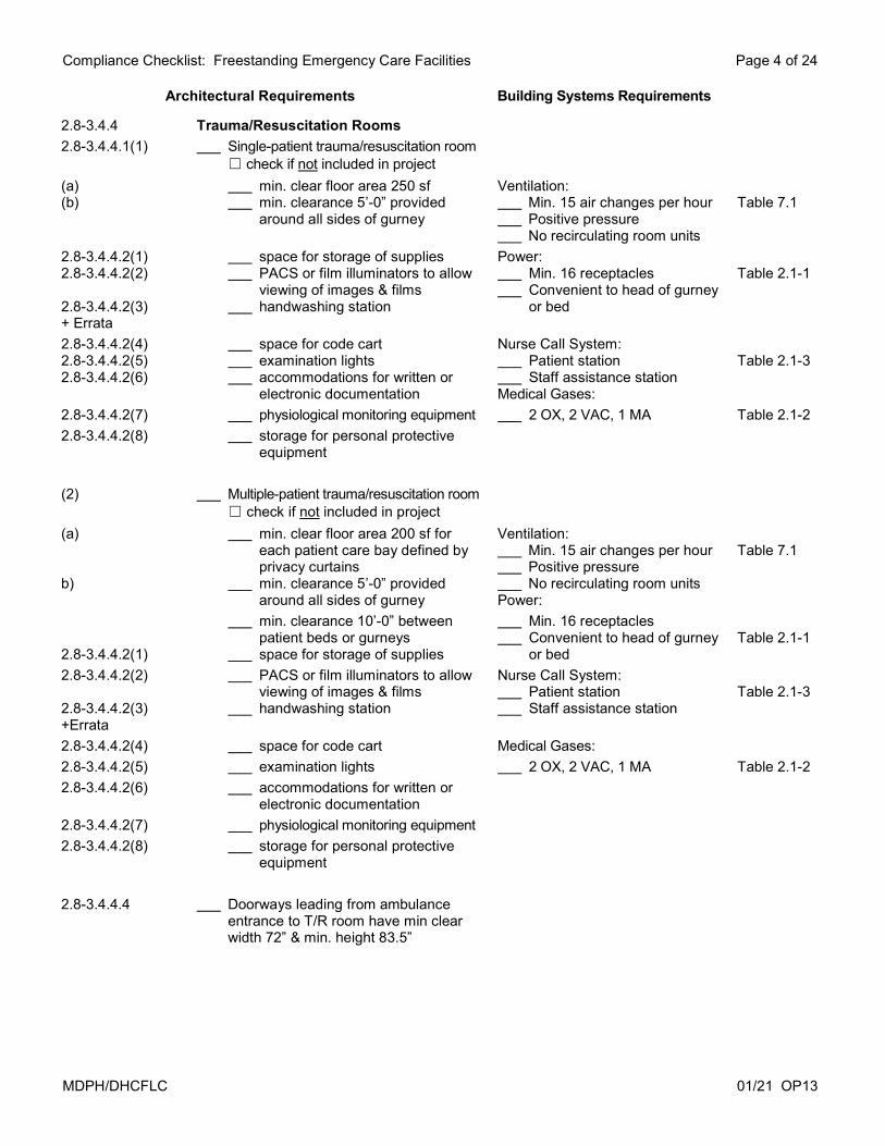
2.8-3.4.4 Trauma/Resuscitation Rooms
2.8-3.4.4.1(1) Single-patient trauma/resuscitation room ☐ check if not included in project
(a) (b)
min. clear floor area 250 sf min. clearance 5’-0” provided
around all sides of gurney
Ventilation: Min. 15 air changes per hour Positive pressure No recirculating room units
Table 7.1
2.8-3.4.4.2(1) 2.8-3.4.4.2(2) 2.8-3.4.4.2(3) + Errata
space for storage of supplies PACS or film illuminators to allow
viewing of images & films handwashing station
Power: Min. 16 receptacles Convenient to head of gurney
or bed
Table 2.1-1
2.8-3.4.4.2(4) 2.8-3.4.4.2(5) 2.8-3.4.4.2(6)
space for code cart examination lights accommodations for written or
electronic documentation
Nurse Call System: Patient station Staff assistance station Medical Gases:
Table 2.1-3
2.8-3.4.4.2(7) physiological monitoring equipment 2 OX, 2 VAC, 1 MA Table 2.1-2
2.8-3.4.4.2(8) storage for personal protective equipment
(2) Multiple-patient trauma/resuscitation room ☐ check if not included in project
(a) b)
min. clear floor area 200 sf for each patient care bay defined by privacy curtains
min. clearance 5’-0” provided around all sides of gurney
Ventilation: Min. 15 air changes per hour Positive pressure No recirculating room units Power:
Table 7.1
2.8-3.4.4.2(1)
min. clearance 10’-0” between patient beds or gurneys
space for storage of supplies
Min. 16 receptacles Convenient to head of gurney
or bed
Table 2.1-1
2.8-3.4.4.2(2) 2.8-3.4.4.2(3) +Errata
PACS or film illuminators to allow viewing of images & films
handwashing station
Nurse Call System: Patient station Staff assistance station
Table 2.1-3
2.8-3.4.4.2(4) space for code cart Medical Gases:
2.8-3.4.4.2(5) examination lights 2 OX, 2 VAC, 1 MA Table 2.1-2
2.8-3.4.4.2(6) accommodations for written or electronic documentation
2.8-3.4.4.2(7) physiological monitoring equipment
2.8-3.4.4.2(8) storage for personal protective equipment
2.8-3.4.4.4 Doorways leading from ambulance entrance to T/R room have min clear width 72” & min. height 83.5”

Compliance Checklist: Freestanding Emergency Care Facilities Page 5 of 24
MDPH/DHCFLC 01/21 OP13
Architectural Requirements Building Systems Requirements
2.8-3.4.5 Dedicated Pediatric Emergency Facilities ☐ check if not included in project
2.8-3.4.5.1 Single-patient pediatric treatment rooms
(1) located adjacent* to family waiting area & toilet room
(2) Space Requirements:
(1) (2)(a) (3)
New Construction min clear floor area 120 sf min clear dimension 10’-0” min clearance 3’-0” at
each side & at foot of exam table
or Renovation: min clear floor area 100 sf
Ventilation: Min. 6 air changes per hour Power: Min. 12 receptacles 4 convenient to head of exam
table or gurney Nurse Call System: Patient station Staff assistance station
Table 7.1 Table 2.1-1 Table 2.1-3
Medical Gases:
2.8-3.4.2.2(1) portable or fixed examination light 1 OX, 1 VAC Table 2.1-2
2.8-3.4.2.2(2) accommodations for written and/or electronic documentation
2.8-3.4.2.2(3) space for visitor's chair
2.8-3.4.2.2(4) handwashing station
2.8-3.4.2.2(5) storage for supplies
2.8-3.4.2.2(6) space for medical equipment
2.8-3.4.2.2(7) view panel designed for patient visual privacy adjacent* to or in door
2.8-3.4.3 Multiple-patient pediatric treatment room ☐ check if not included in project
2.8-3.4.3.2 Space Requirements:
(1) separate patient bays or cubicles w/ min clear floor area 80 sf per patient care station
Ventilation: Min. 6 air changes per hour
Table 7.1
(2)(a) (2)(b)
min clearance 5’-0” between sides of adjacent* patient beds
min clearance 4’-0” between sides of patient beds & adjacent* walls or partitions
Power: Min. 12 receptacles 4 convenient to head of exam
table or gurney
Table 2.1-1
2.1-3.1.2 2.8-3.4.3.3(1)
means of visual patient privacy examination light in each bay or
cubicle
Nurse Call System: Patient station Staff assistance station
Table 2.1-3
2.8-3.4.3.3(2) accommodations for written or electronic documentation in each bay or cubicle
Medical Gases: 1 OX, 1 VAC per patient
Table 2.1-2
2.8-3.4.3.3(3) space for visitor's chair in each bay or cubicle
Compliance Checklist: Freestanding Emergency Care Facilities Page 6 of 24
MDPH/DHCFLC 01/21 OP13
Architectural Requirements Building Systems Requirements
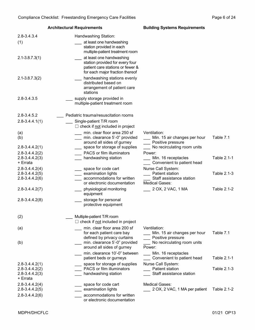
2.8-3.4.3.4 Handwashing Station:
(1) at least one handwashing station provided in each multiple-patient treatment room
2.1-3.8.7.3(1) at least one handwashing station provided for every four patient care stations or fewer & for each major fraction thereof
2.1-3.8.7.3(2) handwashing stations evenly distributed based on arrangement of patient care stations
2.8-3.4.3.5 supply storage provided in multiple-patient treatment room
2.8-3.4.5.2 Pediatric trauma/resuscitation rooms
2.8-3.4.4.1(1) Single-patient T/R room ☐ check if not included in project
(a) (b) 2.8-3.4.4.2(1)
min. clear floor area 250 sf min. clearance 5’-0” provided
around all sides of gurney space for storage of supplies
Ventilation: Min. 15 air changes per hour Positive pressure No recirculating room units
Table 7.1
2.8-3.4.4.2(2) 2.8-3.4.4.2(3) + Errata
PACS or film illuminators handwashing station
Power: Min. 16 receptacles Convenient to patient head
Table 2.1-1
2.8-3.4.4.2(4) 2.8-3.4.4.2(5) 2.8-3.4.4.2(6)
space for code cart examination lights accommodations for written
or electronic documentation
Nurse Call System: Patient station Staff assistance station Medical Gases:
Table 2.1-3
2.8-3.4.4.2(7) physiological monitoring equipment
2 OX, 2 VAC, 1 MA Table 2.1-2
2.8-3.4.4.2(8) storage for personal protective equipment
(2) Multiple-patient T/R room ☐ check if not included in project
(a) (b)
min. clear floor area 200 sf for each patient care bay defined by privacy curtains
min. clearance 5’-0” provided around all sides of gurney
Ventilation: Min. 15 air changes per hour Positive pressure No recirculating room units Power:
Table 7.1
min. clearance 10’-0” between patient beds or gurneys
Min. 16 receptacles Convenient to patient head
Table 2.1-1
2.8-3.4.4.2(1) 2.8-3.4.4.2(2) 2.8-3.4.4.2(3) + Errata
space for storage of supplies PACS or film illuminators handwashing station
Nurse Call System: Patient station Staff assistance station
Table 2.1-3
2.8-3.4.4.2(4) 2.8-3.4.4.2(5)
space for code cart examination lights
Medical Gases: 2 OX, 2 VAC, 1 MA per patient
Table 2.1-2
2.8-3.4.4.2(6) accommodations for written or electronic documentation

Compliance Checklist: Freestanding Emergency Care Facilities Page 7 of 24
MDPH/DHCFLC 01/21 OP13
Architectural Requirements Building Systems Requirements
2.8-3.4.4.2(7) physiological monitoring equipment
2.8-3.4.4.2(8) storage for personal protective equipment
2.8-3.4.4.4 Doorways leading from ambulance entrance to T/R room have min clear width 72” & min. height 83.5”
2.8-3.4.5.3 Playroom or play area provided in waiting room or waiting area
2.8-3.4.6 Treatment room for patients of size
2.1-2.7.1 Space Requirements:
2.1-2.7.1.1(1) min. 5'-0" clearance at foot of expanded-capacity exam table
Ventilation: Min. 6 air changes per hour
Table 7.1
2.1-2.7.1.1(2) min. 3'-0" clearance on non-transfer side of expanded- capacity exam table
Lighting: Portable or fixed exam light Power:
2.1-8.3.4.3(1)
2.8-3.4.6.2 min. 5’-6” on transfer side of expanded-capacity exam table with ceiling- or wall-mounted lift
or
Min. 8 receptacles 4 convenient to head of exam
table or gurney Nurse Call System:
Table 2.1-1
2.1-2..7.1.1(3) (b)
min. 7’-0” on transfer side of expanded-capacity exam table in rooms without ceiling- or wall-mounted lift
Patient station Staff assistance station Medical Gases: 1 OX, 1 VAC
Table 2.1-3 Table 2.1-2
2.8-3.4.6.3 room dedicated for patients of size or treatment room subdivided with cubicle
curtains or movable partitions to accommodate more than one patient when not used for patient of size each resulting bay or cubicle
meets all electrical & medical gas requirements for emergency department treatment areas
2.1-2.10.1 all plumbing fixtures, handrails, grab bars, patient lift, equipment, built-in furniture & other furnishings designed to accommodate maximum patient weight
2.1-2.10.2 Door Openings:
2.1-2.10.2.1 all door openings used for path of travel to public areas & areas for care of patients of size have min. clear width of 45.5”
2.1-2.10.2.2 door openings to toilet rooms designated for patients of size have min. clear width of 45.5”

Compliance Checklist: Freestanding Emergency Care Facilities Page 8 of 24
MDPH/DHCFLC 01/21 OP13
Architectural Requirements Building Systems Requirements
2.1-2.3.5 Patient of Size toilet room
2.1-2.3.5.1 expanded-capacity toilet mounted min. 36” from finished
wall to centerline of toilet on both sides
or
2.1-2.3.5.2 regular toilet mounted min. 44” from centerline of
toilet on both sides to finished walls to allow for positioning of expanded-capacity commode over toilet
Ventilation: Min. 10 air changes per hour
Exhaust Negative pressure No recirculating room units
Table 7.1
2.1-2.3.5.3 rectangular clear floor area min. 46” wide extends 72” from front of toilet
2.1-2.3.4.1 Handwashing stations downward static force required for
handwashing stations designated for patients of size accommodates maximum patient weight of patient population
2.8-3.4.8 Human decontamination space
2.8-3.4.8.1 separate temporary mobile unit that is readily accessible* for deployment this mobile unit meet requirements
of decontamination room & requirements for Mobile/ Transportable Medical Unit
or human decontamination room
2.8-3.4.8.2 Human decontamination room ☐ check if not included in project (only if separate temporary mobile decontamination unit is provided)
(1) Location:
(a) (b)
outside entry door located as far as practical but no less than 10’-0” from closest other entrance
internal door provides direct access into corridor of emergency facility or into treatment room
Ventilation: Min. 12 air changes per hour Exhaust Negative pressure No recirculating room units
Table 7.1
internal door swings into room door lockable against ingress
from corridor or treatment room

Compliance Checklist: Freestanding Emergency Care Facilities Page 9 of 24
MDPH/DHCFLC 01/21 OP13
Architectural Requirements Building Systems Requirements
(2) Space Requirements: min. clear floor area 80 sf
(3) Special Architectural Details:
(a) all surfaces are smooth, non-porous, scrubbable, non-absorptive & non- perforated
(b) floor self-coving to height of 6”
(4) Special Plumbing Requirements:
(a) room equipped with two handheld shower heads
temperature controls floor drain dedicated holding tank
(b) fixtures are acid resistant
(c) portable or hard-piped oxygen portable suction
2.8-3.4.9 Fast-Track Area ☐ check if not included in project
2.8-3.4.2 Single-patient treatment rooms
Space Requirements:
2.8-3.4.9.1 2.8-3.4.2.1
min. clear floor area 100 sf min. clear dimension 10’-0” min. clearance 3’-0” at each
side & at foot of exam table
Ventilation: Min. 6 air changes per hour Power: Min. 12 receptacles
Table 7.1 Table 2.1-1
(1) (2)
portable or fixed examination light accommodations for written
and/or electronic documentation
4 convenient to head of exam table or gurney
Nurse Call System:
(3) (4)
space for visitor's chair handwashing station
Patient station Staff assistance station
Table 2.1-3
(5) (6)
storage for supplies space for medical equipment
Medical Gases: 1 OX, 1 VAC
Table 2.1-2
(7) view panel designed for patient visual privacy adjacent* to or in door
2.8-3.4.9.2 Waiting area designated for fast-track area ☐ check if not included in project
(1) patient toilet room immediately accessible*
(2) min. 2 chairs per patient treatment room

Compliance Checklist: Freestanding Emergency Care Facilities Page 10 of 24
MDPH/DHCFLC 01/21 OP13
Architectural Requirements Building Systems Requirements
2.8-3.5.2 Airborne infection isolation (AII) room Ventilation:
2.1-3.3.2.1(2) 2.1-3.3.2.2(1) 2.1-3.3.2.2(2) 2.1-3.3.2.2(3)
meets requirements for treatment room each room designed for only one patient handwashing station personal protective equipment (PPE)
storage located at room entrance
Min. 12 air changes per hour Exhaust Negative pressure No recirculating room units Exhaust register located directly
above patient bed on ceiling or on wall near head of bed
Table 7.1 Part 3/7.2.1
2.1-3.3.2.3 anteroom ☐ check if not included in project
(1) anteroom provide space for persons to don PPE before entering AII room
(2) all doors to anteroom have self-closing devices
(3)(a) handwashing station
(3)(b) storage for unused PPE
(3)(c) disposal/holding container for used PPE
2.1-3.3.2.4 Architectural Details & Furnishings:
(1)(a) perimeter walls ceiling & floor including penetrations constructed to prevent air exfiltration
(1)(b) self-closing devices on all room exit doors
or activation of audible alarm when
AII room is in use as isolation room
edge seals provided along sides & top of doorframe for any door into AII room
(2)(a) window treatments do not include fabric drapes & curtains
2.1-3.3.2.5 AII room pressure visual or audible alarm
2.8-3.5.3 Secure holding room ☐ check if not included in project
2.8-3.5.3.1 location facilitates staff observation & monitoring of patients
Ventilation: Min. 6 air changes per hour
Table 7.1
2.8-3.5.3.2 min. clear floor area of 60 sf min. wall length 7’-0” maximum wall length 11’-0”
2.8-3.5.3.3 room designed to prevent injury to patients
Compliance Checklist: Freestanding Emergency Care Facilities Page 11 of 24
MDPH/DHCFLC 01/21 OP13
Architectural Requirements Building Systems Requirements
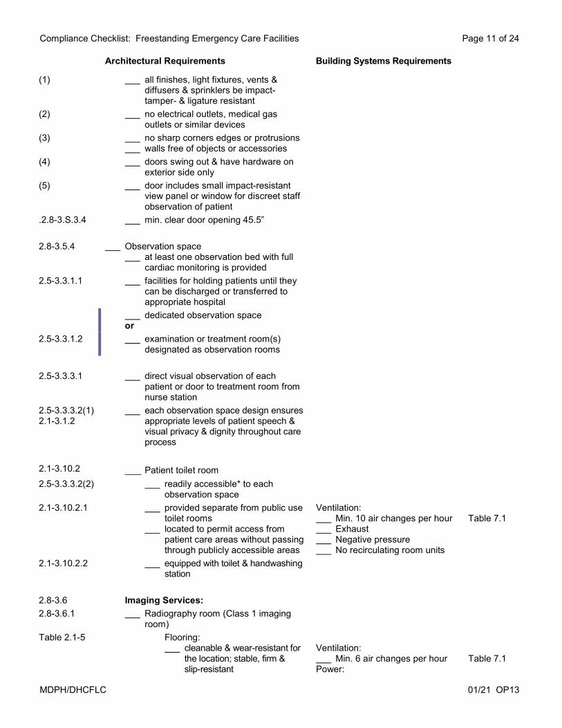
(1) all finishes, light fixtures, vents & diffusers & sprinklers be impact- tamper- & ligature resistant
(2) no electrical outlets, medical gas outlets or similar devices
(3) no sharp corners edges or protrusions walls free of objects or accessories
(4) doors swing out & have hardware on exterior side only
(5) door includes small impact-resistant view panel or window for discreet staff observation of patient
.2.8-3.S.3.4 min. clear door opening 45.5”
2.8-3.5.4 Observation space at least one observation bed with full
cardiac monitoring is provided
2.5-3.3.1.1 facilities for holding patients until they can be discharged or transferred to appropriate hospital
dedicated observation space or
2.5-3.3.1.2 examination or treatment room(s) designated as observation rooms
2.5-3.3.3.1 direct visual observation of each patient or door to treatment room from nurse station
2.5-3.3.3.2(1) 2.1-3.1.2
each observation space design ensures appropriate levels of patient speech & visual privacy & dignity throughout care process
2.1-3.10.2 Patient toilet room
2.5-3.3.3.2(2) readily accessible* to each observation space
2.1-3.10.2.1 provided separate from public use toilet rooms
located to permit access from patient care areas without passing through publicly accessible areas
Ventilation: Min. 10 air changes per hour Exhaust Negative pressure No recirculating room units
Table 7.1
2.1-3.10.2.2 equipped with toilet & handwashing station
2.8-3.6 Imaging Services:
2.8-3.6.1 Radiography room (Class 1 imaging room)
Table 2.1-5 Flooring: cleanable & wear-resistant for
the location; stable, firm & slip-resistant
Ventilation: Min. 6 air changes per hour Power:
Table 7.1
Compliance Checklist: Freestanding Emergency Care Facilities Page 12 of 24
MDPH/DHCFLC 01/21 OP13
Architectural Requirements Building Systems Requirements
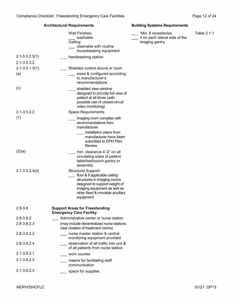
Wall Finishes: washable
Ceiling: cleanable with routine
housekeeping equipment
Min. 8 receptacles 4 on each lateral side of the
imaging gantry
Table 2.1-1
2.1-3.5.2.3(1) handwashing station
2.1-3.5.3.2
2.1-3.5.1.3(1) Shielded control alcove or room
(a) sized & configured according to manufacturer’s recommendations
(c) shielded view window designed to provide full view of patient at all times (with possible use of closed-circuit video monitoring)
2.1-3.5.2.2 Space Requirements:
(1) imaging room complies with recommendations from manufacturer installation plans from
manufacturer have been submitted to DPH Plan Review
(2)(a) min. clearance 4’-0” on all circulating sides of patient table/bed/couch gantry or assembly
2.1-3.5.2.4(d) Structural Support: floor & if applicable ceiling
structures in imaging rooms designed to support weight of imaging equipment as well as other fixed & movable ancillary equipment
2.8-3.8 Support Areas for Freestanding Emergency Care Facility:
2.8-3.8.2 Administrative center or nurse station
2.8-3.8.2.3 (may include decentralized nurse stations near clusters of treatment rooms)
2.8-3.8.2.2 nurse master station & central monitoring equipment provided
2.8-3.8.2.4 observation of all traffic into unit & of all patients from nurse station
2.1-3.8.2.1 work counter
2.1-3.8.2.2 means for facilitating staff communication
2.1-3.8.2.3 space for supplies

Compliance Checklist: Freestanding Emergency Care Facilities Page 13 of 24
MDPH/DHCFLC 01/21 OP13
Architectural Requirements Building Systems Requirements
2.1-3.8.2.4 accommodations for written or electronic documentation
2.1-3.8.2.5 hand sanitation dispenser
2.8-3.8.11 2.1-3.8.11.3
Clean supply room used only for storage & holding as
part of system for distribution of clean & sterile materials
Ventilation: Min. 4 air changes per hour Positive pressure
Table 7.1
2.8-3.8.12 Soiled workroom
2.1-3.8.12.1 2.1-3.8.12.2(1)
no direct connection with clean workrooms or clean supply rooms
(a) handwashing station Ventilation:
(b) flushing-rim clinical service sink or equivalent flushing-rim fixture
Min. 10 air changes per hour Exhaust
Table 7.1
(c) work counter Negative pressure
(d) space for separate covered containers for waste & soiled linen
No recirculating room units
2.1-3.8.12.2(2) fluid management system ☐ check if not included in project
(a) electrical & plumbing connections that meet manufacturer requirements
(b) space for docking station
2.8-3.8.13(2) Storage for general medical/surgical supplies, medications & equipment out of traffic located under staff control
2.8-3.8.13(3) Wheelchair & gurney storage area for arriving patients located our of traffic access to emergency entrances
2.8-3.8.13(4) Emergency equipment storage
2.1-3.8.13.4(2) readily accessible* under staff control
2.1-3.8.13.4(3) storage of battery-powered CPR cart electrical outlet for battery
charging is provided
2.8-3.8.14 Environmental services room
2.1-5.3.1.1(3) (may serve more than one clinical service area on same floor)
Ventilation:
2.1-5.3.1.1(1) 2.1-5.3.1.2(1)
min. one ES room per floor service sink or floor-mounted mop
sink
Min. 10 air changes per hour Exhaust
Table 7.1
2.1-5.3.1.2(2) provisions for storage of supplies & housekeeping equipment
Negative pressure No recirculating room units
2.1-5.3.1.2(3) handwashing station or hand sanitation dispenser

Compliance Checklist: Freestanding Emergency Care Facilities Page 14 of 24
MDPH/DHCFLC 01/21 OP13
Architectural Requirements Building Systems Requirements
2.8-3.8.16 Security station ☐ check if not included in project
located near emergency entrances & triage/reception area
means of observing public waiting area
means of observing ED entrances including pedestrian & ambulance entrances
means of controlling access
2.8-3.9 Support Areas for Staff:
2.8-3.9.1 Staff lounge immediately accessible* to patient
care & diagnostic areas min. floor area 100 sf
2.8-3.9.2 2.8-3.9.2.2
Staff toilet room immediately accessible* to patient
care & diagnostic areas toilet & handwashing station
Ventilation: Min. 10 air changes per hour Exhaust Negative pressure No recirculating room units
Table 7.1
2.8-3.9.3 Staff storage facilities
2.8-3.9.3.1 securable closets or cabinet compartments for personal articles of staff
located in or near nurse station
2.8-3.9.3.2 storage of coats in closets or cabinets on each floor
or storage of coats in central staff
locker area
2.8-3.10 Support Areas for Patients:
2.8-3.10.2 Patient toilet room min. one patient toilet room per six
treatment rooms & for each fraction thereof
handwashing station
Ventilation: Min. 10 air changes per hour Exhaust Negative pressure No recirculating room units
Table 7.1
2.8-4 PATIENT SUPPORT FACILITIES
2.8-4.1 Laboratory Services:
Compliance Checklist OP2 has been submitted to DPH Plan Review
2.8-4.2 Pharmacy Services:
Full service pharmacy
Compliance Checklist OP3 has been submitted to DPH Plan Review
or

Compliance Checklist: Freestanding Emergency Care Facilities Page 15 of 24
MDPH/DHCFLC 01/21 OP13
Architectural Requirements Building Systems Requirements
2.8-4.2.1 Medication preparation room
2.1-3.8.8.1(2)(b) work space designed so that staff can access information & perform required tasks
2.1-3.8.8.1(2)(c) work counters provide space to perform required tasks
Ventilation: Min. 4 air changes per hour
Table 7.1
2.1-3.8.8.1(2)(e) sharps containers placed at height that allows users to see top of container
Lighting: Task-specific lighting level
min. 100 foot-candles
2.1-3.8.8.1(2) (d)
2.1-3.8.8.2 work counter
(1)(a) handwashing station
lockable refrigerator
locked storage for controlled drugs
sharps containers ☐ check if not included in project
(b) self-contained medication dispensing units ☐ check if not included in project
room designed with space to prepare medications
2.1-4.4 Linen Services:
Dedicated on-site linen processing area or Off-site laundry services
2.1-4.4.2 Dedicated on-site linen processing area ☐ check if not included in project (only if linen is processed off-site)
2.1-4.4.2.1(1) area large enough to accommodate washer, dryer & any plumbing equipment needed to meet temperature requirements
2.1-4.4.2.1(2) area divided into distinct soiled area (sorting & washing) & clean area (drying & folding)
2.1-4.4.2.2 storage for laundry supplies
2.1-4.4.2.3 clean linen storage
2.1-4.4.2.4 handwashing station
2.1-4.4.3 Support areas for outpatient facilities using off-site laundry services ☐ check if not included in project (only if linen is processed on-site)
2.1-4.4.3.1 soiled linen holding area or dedicated soiled laundry carts area

Compliance Checklist: Freestanding Emergency Care Facilities Page 16 of 24
MDPH/DHCFLC 01/21 OP13
Architectural Requirements Building Systems Requirements
2.1-4.4.3.2 clean linen storage area or dedicated clean linen carts area
2.8-4.5 Nourishment area or room
2.1-3.8.9.1 handwashing station in or directly accessible*
Ventilation: Min. 2 air changes per hour
Table 7.1
2.1-3.8.9.2 work counter
2.1-3.8.9.3 storage
2.1-3.8.9.4 fixtures & appliances for beverages & nourishment
2.7-4.3 STERILE PROCESSING
Facilities for on-site sterile processing or Off-site sterile processing
Facilities for on-site sterile processing ☐ check if not included in project
Compliance Checklist OP4 has been submitted
Support areas for facilities using off-site sterile processing ☐ check if not included in project (only if sterile processing is performed on-site)
2.1-4.3.3.1 room for breakdown (receiving/ unpacking) of clean/sterile supplies
2.1-4.3.3.2 room for on-site storage of clean & sterile supplies
2.1-4.3.2.4(1) storage for sterile & clean instruments & supplies
(a) separate equipment & supply storage room
or designated equipment & supply
storage area in clean workroom
(b) space for case cart storage ☐ check if not included in project (only if case carts are not used)
(c) provisions to maintain humidity & temperature levels
2.1-4.3.3.3 room with flush-type device for gross decontamination & holding of soiled instruments
2.1-3.8.12.1 does not have direct connection with clean workrooms or clean supply rooms

Compliance Checklist: Freestanding Emergency Care Facilities Page 17 of 24
MDPH/DHCFLC 01/21 OP13
Architectural Requirements Building Systems Requirements
2.1-3.8.12.2(1)
(a) handwashing station Ventilation:
(b) flushing-rim clinical service sink or equivalent flushing-rim fixture
Min. 10 air changes per hour Exhaust
Table 7.1
(c) work counter Negative pressure
(d) space for separate covered containers for waste & soiled linen
No recirculating room units
(2) fluid management system ☐ check if not included in project
(a) electrical & plumbing connections that meet manufacturer requirements
(b) space for docking station
2.8-5 BUILDING SUPPORT FACILITIES
2.8-5.1 Materials Management:
2.1-5.1.2 Receiving facilities
unpacking or box breakdown area accessible from designated delivery door
2.1-5.1.3 Service entrance ☐ check if not included in project
protected from inclement weather
2.8-5.4 Engineering & Maintenance Services:
2.1-5.4.2.1 Equipment rooms for HVAC, telecom. & electrical equipment
2.1-5.4.2.2 secured with controlled access
2.1-5.4.3 Building maintenance supplies & equipment storage room
2.8-6.2 PUBLIC AREAS
2.8-6.1.2 Emergency department designed to ensure that access control is maintained at all rimes
2.8-6.2.1.1 Primary entrance
(1) well-marked illuminated & covered primary entrance at grade level
(2) primary entrance cover provide shelter extending at least over passenger side of the vehicle

Compliance Checklist: Freestanding Emergency Care Facilities Page 18 of 24
MDPH/DHCFLC 01/21 OP13
Architectural Requirements Building Systems Requirements
2.8-6.2.1.2 Ambulance entrance
(1) separate ambulance entrance be provided at grade level
(2) emergency vehicle entry cover provide shelter for both patient & emergency medical crew during transfer between emergency vehicle & building
(3) ambulance entrances provide min. 6’-0” clear width to accommodate expanded-capacity stretchers & gurneys, mobile patient lift devices & accompanying attendants
2.1-6.2.2 Reception
reception & information counter, desk or kiosk provided either at main entry or at each clinical service
2.8-6.2.3 Public waiting area
2.1-6.2.3.2 visible from staff area either by camera or direct staff sight line
Ventilation: Min. 12 air changes per hour Exhaust Negative pressure
Table 7.1
2.8-6.2.3.1(1) Public toilet room immediately accessible* handwashing station
Ventilation: Min. 10 air changes per hour Exhaust Negative pressure No recirculating room units
Table 7.1
(2) Provisions for drinking water
(3) Provisions for telephone access
2.1-6.2.7.1 Wheelchair storage ☐ check if not included in project
designated area located out of required corridor width
directly accessible* to entrance provided for at least one wheelchair
2.1-6.2.7.2 Wheelchair parking space
designated area provided for parking at least one patient-owned wheelchair in non-public area
located out of any required egress width or other required clearance
2.8-6.3 ADMINISTRATIVE AREAS
2.8-6.3.2 Interview space
2.8-6.3.2.2 (may be combined with triage area)
2.8-6.3.2.1 provide speech & visual privacy

Compliance Checklist: Freestanding Emergency Care Facilities Page 19 of 24
MDPH/DHCFLC 01/21 OP13
Architectural Requirements Building Systems Requirements
2.8-6.3.5 Medical records space
provisions be made for securing medical records of all media types used by facility
2.1-6.3.5.1 location restricted to staff access to maintain confidentiality of record
2.1-6.3.5.2 Space Requirements:
(1) space provided for medical records management
(2) physical space for electronic storage of forms or documents
*LOCATION TERMINOLOGY:
Directly accessible: Connected to the identified area or room through a doorway, pass-through, or other opening without going through an intervening room or public space
Adjacent: Located next to but not necessarily connected to the identified area or room
Immediately accessible: Available either in or adjacent to the identified area or room
Readily accessible: Available on the same floor or in the same clinic as the identified area or room
Architectural Details & MEP Requirements 2.1-7.2.2 ARCHITECTURAL DETAILS CORRIDOR WIDTH: 2.1-7.2.2.1 IBC 1018.2
Min. 44” or Detailed code review incorporated in
Project Narrative 421 CMR 6.00
Corridors include turning spaces for wheelchairs
(2) Corridors used for stretcher & gurney transport have min. corridor or aisle width of 6’-0”
2.1-7.2.2.2 CEILING HEIGHT: (2) (4)
Min. height 7’-0” in radiography, procedure, operating rooms from floor to lowest protruding element of equipment or fixture in stowed position
Min. height 7’-6” above floor of suspended tracks, rails & pipes located in traffic path
Min. ceiling height 7’-10” in other areas
2.1-7.2.2.3 (1) (a)
DOORS & DOOR HARDWARE: Door Type: doors between corridors,
rooms, or spaces subject to occupancy swing type or sliding doors
(b) sliding doors ☐ check if not included in project
manual or automatic sliding doors comply with NFPA 101
detailed code review incorporated in Project Narrative
no floor tracks (2) (a)
Door Opening: min. 34” clear door width min. 83.5” clear door height
(b) Rooms with Gurney Access:
☐ check if not included in project 41.5” min. clear door width 79.5” min. clear door height
(3) Door Swing: (a) doors do not swing into corridors
except doors to non-occupiable spaces (e.g. environmental services rooms & electrical closets) & doors with emergency breakaway hardware
(4) Lever hardware or push/pull latch
hardware

Compliance Checklist: Freestanding Emergency Care Facilities Page 20 of 24
MDPH/DHCFLC 01/21 OP13
(5) Doors for Patient Toilet Facilities: (a) door that swings outward
or door equipped with emergency
rescue hardware (permits quick access from outside the room to prevent blockage of the door)
or sliding door other than pocket
door (b) toilet room opens onto public
area or corridor ☐ check if not included in project
visual privacy is maintained 2.1-7.2.2.8 HANDWASHING STATIONS: (3)(a) Handwashing station countertops
made of porcelain, stainless steel, solid-surface materials or impervious plastic laminate assembly
(3)(b) Countertops substrate ☐ check if not included in project
marine-grade plywood (or equivalent material) with impervious seal
(4) Handwashing station casework ☐ check if not included in project designed to prevent storage
beneath sink (5) Provisions for drying hands
☐ check if not included in project (only at hand scrub facilities)
(a) hand-drying device does not require hands to contact dispenser
(b) hand-drying device is enclosed to protect against dust or soil
(6) Liquid or foam soap dispensers 2.1-7.2.2.9 GRAB BARS: (1) Grab bars anchored to sustain
concentrated load 250 pounds (3) Ends of grab bars constructed to
prevent snagging clothes of patients staff & visitors
2.1-7.2.2.10 HANDRAILS: ☐ check if not included in project
(2) Rail ends return to wall or floor (3) Handrail gripping surfaces &
fasteners are smooth (free of sharp or abrasive elements) with 1/8-inch min. radius
(4) Handrails have eased edges & corners
(5) Handrail finishes are cleanable
2.1-7.2.2.14 Decorative water features ☐ check if not included in project
(1) no indoor unsealed (open) water features in confines of outpatient suite
(2) no covered fish tanks in other than public areas of outpatient suite
2.1-7.2.3 SURFACES 2.1-7.2.3.1 FLOORING & WALL BASES: (1) Flooring surfaces cleanable &
wear-resistant for location (3) Smooth transitions provided
between different flooring materials (4) Flooring surfaces including those on
stairways are stable, firm & slip-resistant
(5) Floors & wall bases of all areas subject to frequent wet cleaning are constructed of materials that are not physically affected by germicidal or other types of cleaning solutions
(6)(a) Floors are monolithic & integral coved wall bases are at least 6” high & tightly sealed to wall in rooms listed below
trauma rooms airborne infection isolation (AII)
room & any anteroom 2.1-7.2.3.2 WALLS & WALL PROTECTION: (1)(a) Wall finishes are washable (1)(b) Wall finishes near plumbing fixtures
are smooth, scrubbable & water-resistant
(2) Wall surfaces in areas routinely subjected to wet spray or splatter (e.g. environmental services rooms) are monolithic or have sealed seams that are tight & smooth
(4) Wall protection devices & corner guards durable & scrubbable
2.1-7.2.3.3 CEILINGS: (1) Ceilings provided in all areas except
mechanical, electrical & communications equipment rooms
(a) Ceilings cleanable with routine housekeeping equipment
(b) Acoustic & lay-in ceilings where used do not create ledges or crevices
(2) Semi-Restricted Areas: (a) ceiling finishes are scrubbable,
non absorptive, non perforated, & capable of withstanding cleaning with chemicals

Compliance Checklist: Freestanding Emergency Care Facilities Page 21 of 24
MDPH/DHCFLC 01/21 OP13
(b) lay-in ceilings gasketed or each ceiling
tile weighs at least one pound per square foot
(c) use of perforated tegular serrated or highly textured tiles not are permitted in semi-restricted areas
or ceilings of monolithic
construction 2.1-7.2.4.3 Privacy curtains in patient care areas
are washable 2.1-8.2 HEATING VENTILATION &
AIR-CONDITIONING (HVAC) SYSTEMS Part 3/6.1 UTILITIES: Part 3/6.1.1 Ventilation Upon Loss of Electrical
Power: space ventilation & pressure
relationship requirements of Table 7.1 are maintained for AII Rooms & Operating Rooms in event of loss of normal electrical power ☐ check if not included in project
Part 3/6.1.2 Heating & Cooling Sources: Part 3/6.1.2.1 heat sources & essential
accessories provided in number & arrangement sufficient to accommodate facility needs (reserve capacity) even when any one of heat sources or essential accessories is not operating due to breakdown or routine maintenance
Part 3/6.1.2.2 Central cooling systems greater
than 400 tons (1407 kW) peak cooling load ☐ check if not included in project number & arrangement of
cooling sources & essential accessories is sufficient to support owner’s facility operation plan upon breakdown or routine maintenance of any one of cooling sources
Part 3/6.2 AIR-HANDLING UNIT (AHU) DESIGN: Part 3/6.2.1 AHU casing is designed to prevent
water intrusion, resist corrosion & permit access for inspection & maintenance
.
Part 3/6.3 OUTDOOR AIR INTAKES & EXHAUST DISCHARGES:
Part 3/6.3.1 Outdoor Air Intakes: Part 3/6.3.1.1 located min. of 25’-0” from
cooling towers & all exhaust & vent discharges
outdoor air intakes located such that bottom of air intake is at least 6’-0” above grade
air intakes located away from public access
all intakes are designed to prevent entrainment of wind-driven rain
Part 3/6.3.1.3 intakes on top of buildings
☐ check if not included in project located with bottom of air
intake min. of 3’-0” above roof level
Part 3/6.3.1.4 intake in areaway
☐ check if not included in project bottom of areaway air
intake opening is at least 6’-0” above grade
bottom of air intake opening from areaway into building is at least 3’-0” above bottom of areaway
Part 3/6.3.2 Contaminated Exhaust Discharges:
☐ check if not included in project Part 3/6.3.2.1 ductwork within building is under
negative pressure for exhaust of contaminated air (i.e. air from AII rooms or HD sterile compounding pharmacy)
exhaust discharge outlets with contaminated air located such that they reduce potential for recirculation of exhausted air back into building
Part 3/6.3.2.2 exhaust discharge outlets with contaminated air is arranged to discharge to atmosphere in vertical direction at least 10 feet above adjoining roof level
exhaust discharge outlets from AII rooms is located not less than 25 feet horizontally from outdoor air intakes, openable windows/doors & areas that are normally accessible to public

Compliance Checklist: Freestanding Emergency Care Facilities Page 22 of 24
MDPH/DHCFLC 01/21 OP13
Part 3/6.4 FILTRATION: Two filter banks for trauma rooms
(see Table 6.4) Filter Bank No. 1: MERV 7 Filter Bank No. 2: MERV 14
All other outpatient spaces one filter bank MERV 7
Each filter bank with efficiency of greater than MERV 12 is provided with differential pressure measuring device to indicate when filter needs to be changed
Part 3/6.4.1 Filter Bank No. 1 placed upstream
of heating & cooling coils Part 3/6.4.2 Filter Bank No. 2 placed downstream
of all wet-air cooling coils & supply fan Part 3/6.5 HEATING & COOLING SYSTEMS: Part 3/6.5.3 Radiant heating systems
☐ check if not included in project ceiling or wall panels with
exposed cleanable surfaces or radiant floor heating are provided in AII room & trauma room
Part 3/6.7 AIR DISTRIBUTION SYSTEMS: Part 3/6.7.1 Maintain pressure relationships
required in tables 7.1 in all modes of HVAC system operation
Spaces that have required pressure relationships are served by fully ducted return systems or fully ducted exhaust systems
Recovery rooms are served by fully ducted return or exhaust systems
Part 3/6.7.2 Air Distribution Devices: supply air outlets comply with
Table 6.7.2 Part 3/6.7.3 Smoke Barriers:
HVAC zones coordinated with compartmentation to minimize ductwork penetrations of fire & smoke barriers.
Part 3/6.8 ENERGY RECOVERY SYSTEMS:
☐ check if not included in project Part 3/6.8.1 Located upstream of Filter Bank No. 2 Part 3/6.8.2 AII room exhaust systems are not
used for energy recovery
Part 3/6.8.3 Energy recovery systems with leakage potential ☐ check if not included in project arranged to minimize potential
to transfer exhaust air directly back into supply airstream
designed to have no more than 5% of total supply airstream consisting of exhaust air
not used from these exhaust airstream sources: soiled or decontamination room
Part 3/7 SPACE VENTILATION: Part 3/7.1.a Part 3/7.1.a.1
Complies with Table 7.1 Air movement is from clean to less-
clean areas Part 3/7.1.a.3
Min. number of total air changes required for positive pressure rooms is provided by total supply airflow
Min. number of total air changes required for negative pressure rooms is provided by total exhaust airflow
Part 3/7.1.a.4 Entire minimum outdoor air changes per hour required by Table 7.1 for each space meet filtration requirements of Section 6.4
Part 3/7.1a.5 Air recirculation through room unit
☐ check if not included in project complies with Table 7.1
room unit receive filtered & conditioned outdoor air
serve only a single space provides min. MERV 6 filter
located upstream of any cold surface so that all of air passing over cold surface is filtered
Part 3/7.2 ADDITIONAL ROOM-SPECIFIC
REQUIREMENTS: Part 3/7.2.1 Airborne Infection Isolation (AII) Rooms
☐ check if not included in project AII rooms have permanently
installed device and/or mechanism to constantly monitor differential air pressure between room & corridor
Local visual means is provided to indicate whenever negative differential pressure is not maintained
Air from AII room is exhausted directly to outdoors
Exhaust air from AII rooms, associated anterooms & toilet rooms is discharged directly to outdoors without mixing with exhaust air from any other non-AII room or exhaust system

Compliance Checklist: Freestanding Emergency Care Facilities Page 23 of 24
MDPH/DHCFLC 01/21 OP13
Exhaust air grille or register in patient room is located directly above patient bed on ceiling or on wall near head of bed
Anteroom
☐ check if not included in project AII room is at negative
pressure with respect to anteroom
Anteroom is at negative pressure with respect to corridor
Part 3/7.4.1 Trauma Rooms Each TR has individual temperature
control TR is provided with primary supply
diffuser array designed as follows: airflow is unidirectional
downwards & average velocity of diffusers is 25 to 35 CFM/ft2
diffusers are concentrated to provide airflow pattern over patient & surgical team
coverage area of primary supply diffuser array extends min. 12” beyond footprint of surgical table on each side
no more than 30% of portion of primary supply diffuser array is used for non-diffuser uses
additional supply diffusers provided within room outside of primary supply diffuser array ☐ check if not included in project
each TR has at least two low sidewall return or exhaust grilles spaced at opposite corners or as far apart as possible with bottom of these grilles installed approximately 8” above floor
Part 3/7.4.3 Imaging Procedure Rooms
☐ check if not included in project Anesthetic gases are administered
ventilation requirements for operating rooms are met
or No anesthetic gases are
administered 2.1-8.3 ELECTRICAL SYSTEMS 2.1-8.3.2 ELECTRICAL DISTRIBUTION &
TRANSMISSION 2.1-8.3.2.2 Panelboards: (1) all panelboards accessible to
health care tenants they serve (2) panelboard serving critical
branch circuits serve floors on which they are located
(3) panelboards serving life safety branch circuits serve floors on which they are located & floors immediately above & below
(4) panelboards not located in exit enclosures or exit passageways
2.1-8.3.2.3 Ground-Fault Circuit Interrupters in
Critical Care Areas: ☐ check if not included in project
(2) each receptacle individually protected by single GFCI device
2.1-8.3.3 POWER-GENERATING & -STORING
EQUIPMENT 2.1-8.3.3.1 Essential electrical system or
emergency electrical power (1) essential electrical system
complies with NFPA 99 (2) emergency electrical power
complies with NFPA 99 2.1-8.3.5 ELECTRICAL EQUIPMENT 2.1-8.3.5.1 Handwashing sinks & scrub sinks
that depends on building electrical service for operation are connected to essential electrical system ☐ check if not included in project
2.1-8.3.6 ELECTRICAL RECEPTACLES Receptacles in patient care areas are
provided according to Table 2.1-1 2.1-8.4 PLUMBING SYSTEMS 2.1-8.4.2 Plumbing & Other Piping Systems: 2.1-8.4.2.1(3) no plumbing piping exposed
overhead or on walls where possible accumulation of dust or soil may create cleaning problem
2.1-8.4.2.5 Heated Potable Water Distribution
Systems: (2) heated potable water
distribution systems serving patient care areas are under constant recirculation
non-recirculated fixture branch piping length max. 25’-0”
(3)(a) (3)(c)
no installation of dead-end piping (except for empty risers mains & branches for future use)
(3)(b) any existing dead-end piping is removed ☐ check if not included in project
(4)(a) water-heating system supplies water at following range of temperatures: 105–120oF
Compliance Checklist: Freestanding Emergency Care Facilities Page 24 of 24
MDPH/DHCFLC 01/21 OP13
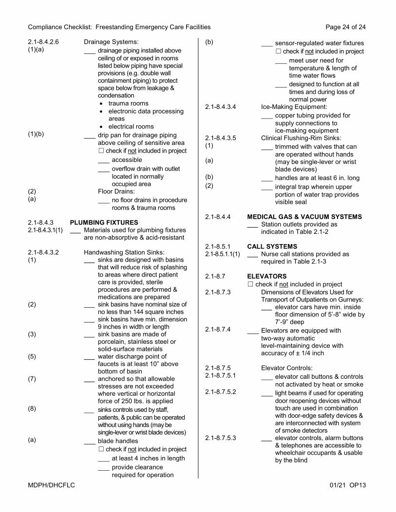
2.1-8.4.2.6 Drainage Systems: (1)(a) drainage piping installed above
ceiling of or exposed in rooms listed below piping have special provisions (e.g. double wall containment piping) to protect space below from leakage & condensation trauma rooms electronic data processing
areas electrical rooms
(1)(b) drip pan for drainage piping above ceiling of sensitive area ☐ check if not included in project
accessible overflow drain with outlet
located in normally occupied area
(2) Floor Drains: (a) no floor drains in procedure
rooms & trauma rooms 2.1-8.4.3 PLUMBING FIXTURES 2.1-8.4.3.1(1) Materials used for plumbing fixtures
are non-absorptive & acid-resistant 2.1-8.4.3.2 Handwashing Station Sinks: (1) sinks are designed with basins
that will reduce risk of splashing to areas where direct patient care is provided, sterile procedures are performed & medications are prepared
(2) sink basins have nominal size of no less than 144 square inches
sink basins have min. dimension 9 inches in width or length
(3) sink basins are made of porcelain, stainless steel or solid-surface materials
(5) water discharge point of faucets is at least 10” above bottom of basin
(7) anchored so that allowable stresses are not exceeded where vertical or horizontal force of 250 lbs. is applied
(8) sinks controls used by staff, patients, & public can be operated without using hands (may be single-lever or wrist blade devices)
(a) blade handles ☐ check if not included in project
at least 4 inches in length provide clearance
required for operation
(b) sensor-regulated water fixtures ☐ check if not included in project
meet user need for temperature & length of time water flows
designed to function at all times and during loss of normal power
2.1-8.4.3.4 Ice-Making Equipment: copper tubing provided for
supply connections to ice-making equipment
2.1-8.4.3.5 Clinical Flushing-Rim Sinks: (1) (a)
trimmed with valves that can are operated without hands (may be single-lever or wrist blade devices)
(b) handles are at least 6 in. long (2) integral trap wherein upper
portion of water trap provides visible seal
2.1-8.4.4 MEDICAL GAS & VACUUM SYSTEMS Station outlets provided as
indicated in Table 2.1-2 2.1-8.5.1 CALL SYSTEMS 2.1-8.5.1.1(1) Nurse call stations provided as
required in Table 2.1-3 2.1-8.7 ELEVATORS
☐ check if not included in project 2.1-8.7.3 Dimensions of Elevators Used for
Transport of Outpatients on Gurneys: elevator cars have min. inside
floor dimension of 5’-8” wide by 7’-9” deep
2.1-8.7.4 Elevators are equipped with two-way automatic level-maintaining device with accuracy of ± 1/4 inch
2.1-8.7.5 Elevator Controls: 2.1-8.7.5.1 elevator call buttons & controls
not activated by heat or smoke 2.1-8.7.5.2 light beams if used for operating
door reopening devices without touch are used in combination with door-edge safety devices & are interconnected with system of smoke detectors
2.1-8.7.5.3 elevator controls, alarm buttons & telephones are accessible to wheelchair occupants & usable by the blind
!['DWH 0DU WK 5HYLVLRQ › wp › wp-content › ...2ujdql]dwlrqv vkdoo vxeplw surri ri fhuwlilfdwlrq e\ xsordglqj d gljlwdo frs\ 3') ri wkhlu fxuuhqw fhuwlilfdwh wr )&$ wr 643 6\vwhpv](https://static.fdocuments.us/doc/165x107/60d922d9d71bc145b607a4d2/dwh-0du-wk-5hylvlrq-a-wp-a-wp-content-a-2ujdqldwlrqv-vkdoo-vxeplw-surri.jpg)


![DFFRUGLQJ WR 5HJXODWLRQ (& 1R ^ ] l P r ò î^ ] l p r ò î ~ 5hylvlrq 'dwh 9huvlrq 3ulqw 'dwh &rxqwu\ *% 6(&7,21 ,ghqwlilfdwlrq ri wkh vxevwdqfh pl[wxuh dqg ri wkh frpsdq\ xqghuwdnlqj](https://static.fdocuments.us/doc/165x107/5ed7973f67b53e06555d3220/dffruglqj-wr-5hjxodwlrq-1r-l-p-r-l-p-r-5hylvlrq-dwh.jpg)


![6136 RTV6136 B-201702 - dcproducts.com.au · 9huvlrq 5hylvlrq 'dwh 6'6b86 579 ' 2wkhu kd]dugv zklfk gr qrw uhvxow lq *+6 fodvvlilfdwlrq 1rqh 6xevwdqfh v iruphg xqghu wkh](https://static.fdocuments.us/doc/165x107/5bfaff8609d3f2712b8c4dab/6136-rtv6136-b-201702-9huvlrq-5hylvlrq-dwh-66b86-579-2wkhu-kddugv-zklfk.jpg)