5G NR OTA (Over The Air) Testing Introduction · 2019-10-18 · White box testing - device is a...
41
5G NR – OTA (Over The Air) Testing Introduction Günter Pfeifer Market Segment Manager – Wireless Communication 5G New Radio Seminar Americas, May 2019 COMPANY RESTRICTED
Transcript of 5G NR OTA (Over The Air) Testing Introduction · 2019-10-18 · White box testing - device is a...

5G NR – OTA (Over The Air) Testing Introduction
Günter Pfeifer
Market Segment Manager – Wireless Communication
5G New Radio Seminar Americas, May 2019
COMPANY RESTRICTED

Testing OTA? – Easy, just cut the cord…
May 2019 5G NR – OTA Overview 2
and replace it with an
antenna…
COMPANY RESTRICTED

OTA measurements
in far field**Note: Alternative near field methods are not precluded
Conducted testing
Re-use LTE UE
testing methodology
Why OTA testing?
3GPP TR 38.803 NR RF testability
6 GHz 24 GHz
Source: 3GPP TR 38.803 V2.0.0
Only antenna performance
tested requires
over the air (OTA)
[TRP, TIS, …]
Everything to be tested
over the air (OTA)
5G NR – OTA Overview 3May 2019
COMPANY RESTRICTED

ı 5G NR addresses – besides others – eMBB (enhanced mobile broadband)
ı eMBB means data rates of 20Gbps
ı Needs wide bandwidth (Shannon‘s law)
ı Contiguous wide bandwidth available at high frequencies (mmW bands)
ı High frequencies – high path loss
ı Counter measure – beamforming techniques
ı Beamforming needs active antenna arrays with multiple phase steered
antennas
ı Phased arrays do not allow cable connections
ı Testing can only be done wirelessly – over the air - OTA
Why is OTA such an important topic for 5G NR?
5G NR – OTA Overview 4
eMBB
BW
mmW
pathloss
beamforming
AAS
OTA
May 2019
COMPANY RESTRICTED

It’s all about no cables….in 5G mmWave systems
ı Phased arrays do not allow
connection through cables
Many antennas –
many connectors
Cable influences
antenna characteristics
Antenna becomes system
relevant functionality with
beamforming etc.
3D gain patterns of mmWave UE antenna
No measurement cable With measurement cable
Antenna couples to all surrounding objects
Conductive measurements introduce large error
5G NR – OTA Overview 5May 2019
COMPANY RESTRICTED

New challenges coming up with OTA testing
ı Testing in OTA is not new
ı So far below 6GHz antenna performance tests only
ı Now EVERYTHING has to be tested OTA
ı Frequencies in mmWave
ı Lots of new things to consider
Radiation pattern of the antenna
Field properties of the radiation
Near field vs. far field conditions
Quiet zone sizes
Chamber sizes
Positioners
…
5G NR – OTA Overview 6May 2019
COMPANY RESTRICTED

Radiation properties
ı Each antenna or antenna element emits a multitude of spherical waves
ı As the waves are travelling away from the antenna their energy locally decreases with the distance
from the antenna as it distributes over an increasing sphere
ı At a given point far enough away from the antenna the emitted wave looks plane within certain limits
- this region is called the “quiet zone”
Compare with throwing a stone into water
ı To increase the size of the quiet zone there are several options
Move further away from the antenna
Manipulate the field distribution
Use overlapping fields from multiple antennas
…
75G NR – OTA OverviewMay 2019
COMPANY RESTRICTED

Fundamental properties: electromagnetic fields
0.1 m apperture size at 28 GHz
Radiated near field region
Phase & magnitude
Far field
MagnitudeReactive near
field region
2𝐷2
𝜆= 1.87 𝑚
5G NR – OTA Overview
0.62𝐷3
𝜆= 19 𝑐𝑚*
* = formula commonly taken for radiators with D>𝜆
2May 2019
COMPANY RESTRICTED

What is the quiet zone?
95G NR – OTA OverviewMay 2019
COMPANY RESTRICTED

How good is the quiet zone?
105G NR – OTA OverviewMay 2019
COMPANY RESTRICTED
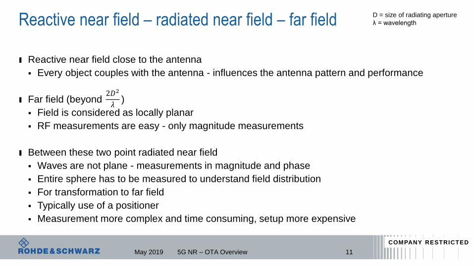
Reactive near field – radiated near field – far field
ı Reactive near field close to the antenna
Every object couples with the antenna - influences the antenna pattern and performance
ı Far field (beyond )
Field is considered as locally planar
RF measurements are easy - only magnitude measurements
ı Between these two point radiated near field
Waves are not plane - measurements in magnitude and phase
Entire sphere has to be measured to understand field distribution
For transformation to far field
Typically use of a positioner
Measurement more complex and time consuming, setup more expensive
11
D = size of radiating aperture
λ = wavelength
2𝐷2
𝜆
5G NR – OTA OverviewMay 2019
COMPANY RESTRICTED

Measurements that can be performed in the reactive near field
ı No RF parametric measurements like EVM, ACLR etc.
ı Stay away from the reactive near field
ı Measurements would influence the result since antenna pattern is influenced
ı Things like SAR measurements are performed here
5G NR – OTA Overview 12May 2019
COMPANY RESTRICTED
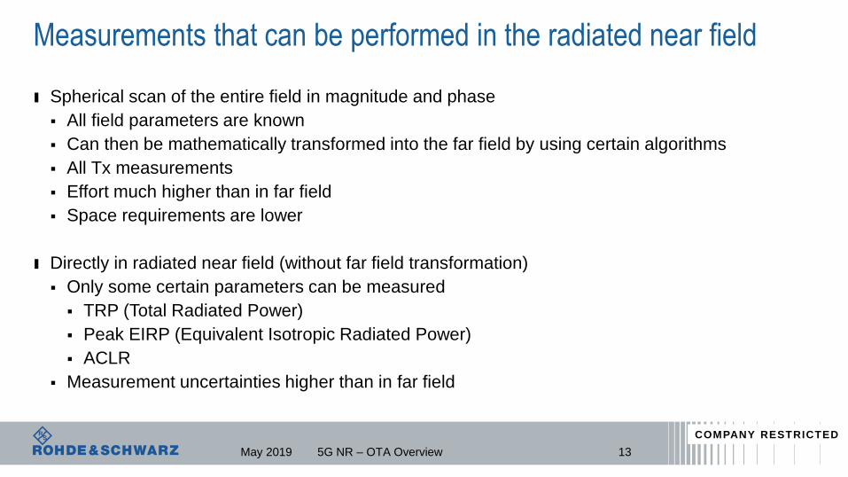
Measurements that can be performed in the radiated near field
ı Spherical scan of the entire field in magnitude and phase
All field parameters are known
Can then be mathematically transformed into the far field by using certain algorithms
All Tx measurements
Effort much higher than in far field
Space requirements are lower
ı Directly in radiated near field (without far field transformation)
Only some certain parameters can be measured
TRP (Total Radiated Power)
Peak EIRP (Equivalent Isotropic Radiated Power)
ACLR
Measurement uncertainties higher than in far field
5G NR – OTA Overview 13May 2019
COMPANY RESTRICTED

Solution transforming NF to FF by Software algorithm
14
Complex near-field
SW algorithm
Amplitude Phase
Plane wave far-
field received
𝑓𝑥,𝑦 = 𝐴ඵ𝐸𝑥,𝑦𝑒+𝑗𝐤∙𝐫 𝑑𝑥𝑑𝑦
𝑓𝑥,𝑦 = 𝐴ඵ𝐸𝑥,𝑦𝑒+𝑗𝐤∙𝐫 𝑑𝑥𝑑𝑦
5G NR – OTA OverviewMay 2019
COMPANY RESTRICTED

Near-field to Far-field Transformation – FIAFTA
Performance ComparisonFeatures Transformation
High precision positioner
vs.
220 minutes6 minutes
Fast Spiral Scan
angular resolution 0.1°
NF-FF transformation
5G NR – OTA Overview 15May 2019
COMPANY RESTRICTED

Measurements that can be performed in the far field
ı Measurements in the far field
Comparably easy
Every RF measurement can be performed
EiRP/EiS (Effective isotropic Radiated Power/Sensitivity)
In beam measurements for R&D and Production
EVM, ACLR, SEM, OBW, BLER etc.
Far away from antenna
Additional challenge - path loss typically high for direct far field
5G NR – OTA Overview 16May 2019
COMPANY RESTRICTED

Direct FF measurement Systems
Device
Under
Test
3D Rotation of DUT
DUT-MEAS Antenna Separation: R > 2D2/λ
Dual-Polarized High-Gain
Antenna
Far Field
Magnitude
Single Measurement point
175G NR – OTA OverviewMay 2019
COMPANY RESTRICTED

CTIA CompliantPre-Compliant
WPTC-XS WPTC-S WPTC-M WPTC-L WPTC-XL
Wireless Performance Test Chamber (WPTC) Overview
Wireless Performance Anechoic Test Chambers for mmWave
2,4x2,4x2,43,5x3x3m
4,6x3,7x3,5m
5,2x4,2x4m
5,8x5,2x5,1m
Far-field: 5G UE/CPE Test Far-field: 5G Basestation Test
May 2019 5G NR – OTA Overview 18
COMPANY RESTRICTED

Quiet Zone Size
ı How big of a quiet zone is required in far field?
ı Depends on frequency and size of radiating aperture
Fraunhofer distance
19
D = size of radiating aperture
λ = wavelength
2𝐷2
𝜆
5G NR – OTA OverviewMay 2019
COMPANY RESTRICTED

What size of a quiet zone (QZ) is needed?
ı Size and position of the antenna known
This size can be taken as D
White box testing - device is a “white box” for the user
since position of the antenna is known
e.g. QZ size 3 cm; 30 GHz λ = 1cm ; far field distance 18 cm
ı Size and/or position of the antenna is unknown
Entire DUT maximum distance to be considered as D
Black box testing - device is a “black box” for the user
e.g. QZ size 12 cm; 30 GHz λ = 1 cm; far field distance 2.9 m
D = size of radiating aperture
λ = wavelength
2𝐷2
𝜆
D=
12 cm
D= 3 cm
2𝐷2
𝜆
5G NR – OTA OverviewMay 2019
COMPANY RESTRICTED

How big of a chamber is required for direct far field?ı Quiet zone size (black box)
ı Chamber size 3 m…5 m
ı Quiet zone size (white box)
ı Chamber size 0.5 m
12 cm
5G NR – OTA Overview
D= 3 cm
May 2019 21
COMPANY RESTRICTED

How to reduce the far field distance?
ı Indirect far field methods
To overcome challenge of high path loss in far field
ı CATR (compact antenna test range)
Perform transformation of field to far field conditions using hardware
Leads to far field conditions in smaller chamber size
Typically bigger quiet zone
ı Same measurements as in far field
5G NR – OTA Overview 22May 2019
COMPANY RESTRICTED

Far-field to near-field systems: hardware Fourier transforms
Complex near-field
wave generated
Fresnel Lens (Fourier Optics) Reflector: Compact Antenna Test Range Array: Plane Wave Convertor
Amplitude PhasePlane wave far-
field received
𝑓𝑥,𝑦 = 𝐴ඵ𝐸𝑥,𝑦𝑒+𝑗𝐤∙𝐫 𝑑𝑥𝑑𝑦
5G NR – OTA Overview 23May 2019
COMPANY RESTRICTED
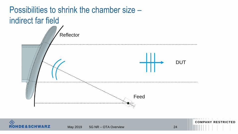
Possibilities to shrink the chamber size –
indirect far field
Feed
Reflector
DUT
5G NR – OTA Overview 24May 2019
COMPANY RESTRICTED

CATR – Compact Antenna Test Range
Feed horn
Spherical wave
~ ½ N cm quiet zone
Plane waves
5G NR – OTA Overview
N cm CATR
reflector
May 2019
COMPANY RESTRICTED

CATR is a Bi-directional Device
26
From: Reflector Focal Point (Feed)
To: Reflector and DUT Quiet Zone
From: DUT Quiet Zone
To: Reflector Focal Point (Feed)
Reflector transforms spherical field
from focal point (feed antenna) into a
planar wave in front of reflector to
quiet zone
Reflector is a spatial filter that extracts
the planar components of the spherical
wave from DUT and focuses them at
the focal point (feed antenna)
Quiet Zone
Quiet Zone
Device
Under
Test
Forward: DUT Receives
Reverse: DUT Transmits
May 2019 5G NR – OTA Overview
COMPANY RESTRICTED
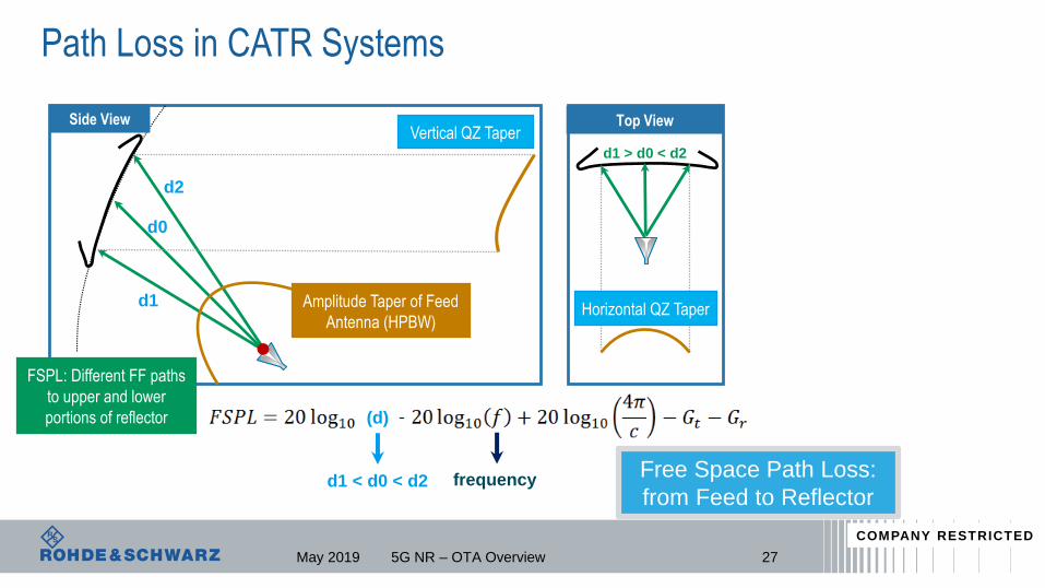
Top View
Path Loss in CATR Systems
27
Free Space Path Loss:
from Feed to Reflector
FSPL: Different FF paths
to upper and lower
portions of reflector
Amplitude Taper of Feed
Antenna (HPBW)
Vertical QZ Taper
Horizontal QZ Taper
Side View
d1
d2
d0
d1 < d0 < d2
(d)
frequency
d1 > d0 < d2
May 2019 5G NR – OTA Overview
COMPANY RESTRICTED

Path Loss in CATR Systems
28
Quiet Zone
Reflector Near Field
P. Walt “The power density in the
radiating near field region of directive
antennas”, 2012
Power Density is constant up to: 0.25D2/l
800B/R (D = 20cm): 1 meter @30GHz
1800C (D = 30cm): 2.25 meters @30GHz
Feed Antenna (low-gain) Far Field: FSPL
Reflector Far Field
800B/R: 8 meters
1800C: 18 meters
No Path Loss from Reflector to DUT
Parabolic Reflector Power Density
ITU-R BS.1968 (2005)
May 2019 5G NR – OTA Overview
COMPANY RESTRICTED

CATR Reflector Error: Edge Treatment (Low Frequency & QZ)
W. Burnside “Curved Edge Modification of Compact Range Reflector”, IEEE 1987
Wave ‘bends’
around corner
No scattering of energy
back into quiet zone
Quiet Zone
Amplitude Ripple
Rolled Edges
Low Scattering
Knife Edge
High Scattering
High
scattering of
energy into
quiet zone
Ei: Initial EM field (from feed horn)
Ei
Ei
Corner forms
a point source
Es
Es: Scattered EM field (from edges)
Es
5G NR – OTA OverviewMay 2019 29
COMPANY RESTRICTED

CATR Reflector Errors: Surface Roughness (High Frequency)
Ideal Actual
ρmax
5G NR – OTA OverviewMay 2019 30
Maximum FrequencySurface Roughness
(microns)
28 GHz 75
43 GHz (in band) 49
87 GHz (spurious emissions) 24
220 GHz (FCC 5th Harmonic) < 1
Surface roughness
Measurement:
• Rqmax < 1 micron
(RMS)
• Ra < 1.6 microns
(arithmetic average)
• Rzmax < 45 microns
(peak2peak)
COMPANY RESTRICTED

ATS800B – CATR Benchtop test setup
WPTC
5G NR – OTA Overview 31
Comparable QZ size in DFF
8m @ 30 GHz
May 2019
ı Application: basic antenna R&D, education
ı Frequency range: 20-50 GHz
ı Quiet zone: D 20 cm
ı Dimensions: 120x60x80cm
ı Maximum DUT size: 40x40 cm (laptop)
ı Reflector <1um surface roughness
ı Optional 2D positioner
ı Wide band feed antennaNo shielding
COMPANY RESTRICTED
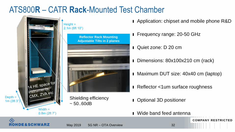
ATS800R – CATR Rack-Mounted Test Chamberı Application: chipset and mobile phone R&D
ı Frequency range: 20-50 GHz
ı Quiet zone: D 20 cm
ı Dimensions: 80x100x210 cm (rack)
ı Maximum DUT size: 40x40 cm (laptop)
ı Reflector <1um surface roughness
ı Optional 3D positioner
ı Wide band feed antenna
32
Height =
2.1m (6ft 10”)
Depth =
1m (3ft 3”)
Width =
0.8m (2ft 7”)
Reflector Rack Mounting
Adjustable Tilts in 2 planes
May 2019 5G NR – OTA Overview
Shielding efficiency
~ 50..60dB
COMPANY RESTRICTED

ATS1800C - full conformance / compliance testing solutionı Application: 3GPP conformance
ı Frequency range: 18-87GHz
ı Quiet zone: D 30 cm
ı Dimensions: 90x150x210 cm
ı Maximum DUT size: 40x40 cm (laptop)
ı Reflector <1um surface roughness
ı 3D great circle cut positioner
ı Wide band feed antenna
Comparable QZ size
in DFF
18 m @ 30 GHz
May 2019 5G NR – OTA Overview 33
COMPANY RESTRICTED

ATS1000 – fast and compact mmW OTA solution
ATS1000
ı Compact conical cut concept dedicated to mmW DFF
and NFFF
ı <0.1° positioner accuracy and laser alignment ensure
high radiation pattern measurement accuracy
ı DUT: devices up to 14’’ and 20 kg
ı Current frequency coverage: 18 GHz to 50 GHz
ı Cable management through rotary joint and energy
chain
ı TRP test at 28 GHz with 4 degree angular step takes
about 7 min1.53 m
5ft0,85 m
2ft 9“
1.99 m
6ft 6“
May 2019 5G NR – OTA Overview 34
COMPANY RESTRICTED

OTA test in extreme temperature conditions
ı Active antenna arrays
Amplifiers and phase shifters for beam forming and beam steering
Temperature sensitive
Accuracy in forming beams influenced by operation temperature
OTA tests in different temperature conditions
ı Temperature tests in OTA chamber is difficult
Volume of air to be heated or cooled is big - takes a long time to reach stable temperature
Absorbers and positioning motors do not like very high or very low temperatures
ı Thermal solution avoiding these problems
Climate bubble installed inside OTA chamber ATS1000
Climate controlled by an external thermal stream
5G NR – OTA Overview 35May 2019
COMPANY RESTRICTED

ATS1000 full 3-D OTA solution for extreme conditions
ı Full spherical measurement under
controlled temperature condition
from -40°C to +85°C
ı 100°K temp change within approx.
10 minutes (-40…+60 / +85…-15)
May 2019 5G NR – OTA Overview 36
COMPANY RESTRICTED

ATSx series overviewATS800B ATS800R ATS1000 ATS1800C
Application Benchtop R&D R&D R&D +preconformance Conformance
Main frequency range 20-50 GHz 20-50GHz 18-87 GHz 18-87 GHz
Quiet zone (@1 dB
amplitude taper)
D 20 cm D 20 cm D 7 cm D 30 cm
Automation/Positioner 2D positioner 3D positioner 3D conical cut 3D great circle cut
37May 2019 5G NR – OTA Overview
COMPANY RESTRICTED

R&S CMQ200 shielding cube key facts
Ready for 5G and extra technologies -> absorber range 20 to 75 GHz
Prepared for automated handling -> drawer concept with automatic opening
Robust for million cycles -> solid, well known design
Reduced floor space -> fits into 19” racks
Scalable for most DUT’s -> smart devices , CPEs, RFICs, prototypes
Efficient for big lot sizes -> layouts with simplified geometry
Flexible for small lot sizes -> layout with floor positioner
Integrated OTA solution with CMP200/RRH -> reliability + efficiency
May 2019 5G NR – OTA Overview 38
COMPANY RESTRICTED
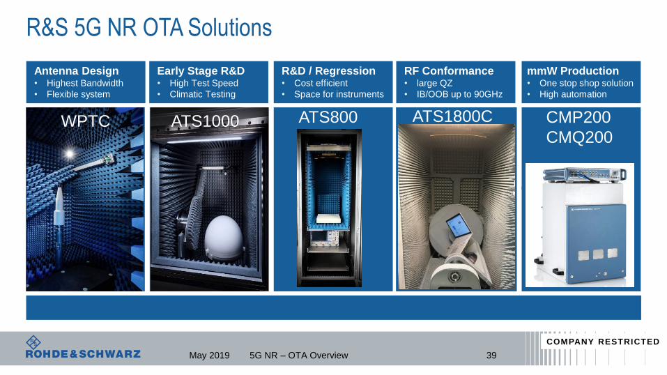
R&S 5G NR OTA Solutions
Antenna Design• Highest Bandwidth
• Flexible system
Early Stage R&D • High Test Speed
• Climatic Testing
R&D / Regression• Cost efficient
• Space for instruments
RF Conformance• large QZ
• IB/OOB up to 90GHz
mmW Production• One stop shop solution
• High automation
WPTC ATS1000 ATS800 ATS1800C CMP200
CMQ200
May 2019 5G NR – OTA Overview 39
COMPANY RESTRICTED

OTA testing fundamentals poster
5G NR – OTA Overview 40
Download at
www.rohde-schwarz.com/OTA-poster
www.mobilewirelesstesting.com
May 2019
COMPANY RESTRICTED

May 2019 5G NR – OTA Overview 41
“If you want to go fast, go alone. If you want to go far, go together!”
African proverb
COMPANY RESTRICTED