5,999,637 - rpx-patents.s3.amazonaws.com · _ apparatus has a calculation processing portion 60....
30
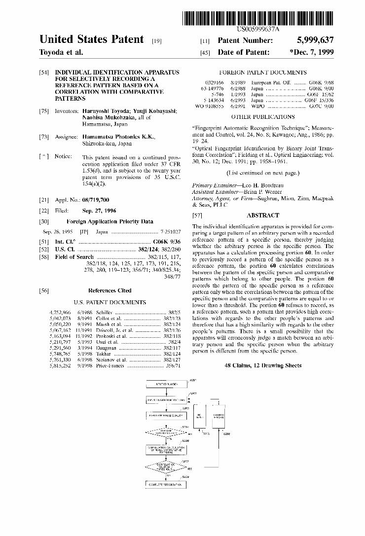
US005999637A United States Patent [19] [11] Toyoda et al. [45] 5,999,637 *Dec. 7, 1999 Patent Number: Date of Patent: [54] INDIVIDUAL IDENTIFICATION APPARATUS FOR SELECTIVELY RECORDING A FOREIGN PATENT DOCUMENTS 211222 ~~~~~~~ ~~ 28 CORRELATION WITH COMPARATIVE 5-746 1/1993 Jagan I. ~~~~~~~~~~~~~~~~~~~~~~ ...~GO6F 15/62 PATTERNS 5-143634 6/1993 Japan .. GO6F 15/336 WO 9108555 6/1991 WIPO ............................ .. G07C 9/00 [75] Inventors: Haruyoshi Toyoda; Yuuji Kobayashi; Naohisa Mukohzaka, all of Hamamatsu, Japan OTHER PUBLICATIONS “Fingerprint Automatic Recognition Technique”; Measure ment and Control; vol. 24, No. 8; KaWagoe; Aug., 1986; pp. 19—24. “Optical Fingerprint Identi?cation by Binary Joint Trans form Correlation”; Fielding et al., Optical Engineering; vol. 30, No. 12; Dec. 1991; pp. 1958—1961. [73] Assignee: Hamamatsu Photonics K.K., ShiZuoka-ken, Japan [*1 Notice? This patent issued on a continued pros ecution application ?led under 37 CFR 1.53(d), and is subject to the tWenty year patent term provisions of 35 U.S.C. 154(a)(2). (List continued on neXt page.) Primary Examiner—Leo H. Boudreau Assistant Examiner—Brian P. Werner Attorney, Agent, or Firm—Sughrue, Mion, Zinn, Macpeak & Seas, PLLC [57] ABSTRACT [21] Appl. No.: 08/719,700 [22] Filed: Sep. 27, 1996 [30] Foreign Application Priority Data The individual identi?cation apparatus is provided for com Sep. 28, 1995 [JP] Japan .................................. .. 7-251027 paring a target pattern of an arbitrary person With a recorded [51] Int. Cl? ..................................................... .. G06K 9/36 reference Patten} of a Speci?c Persom Fhereby judging [52] US. Cl. ........................................... .. 382/124; 382/280 Whether the arbltrary Person IS the Spam?” Person The _ apparatus has a calculation processing portion 60. In order Fleld Of Search ................................... .. to previously record a pattern of the Speci?c person as a 382/118’ 124’ 125’ 127’ 173’ 191’ 218’ reference pattern, the portion 60 calculates correlations 278’ 280’ 119_123; 356/71; 340/825'34; betWeen the pattern of the speci?c person and comparative 348/77 patterns Which belong to other people. The portion 60 records the pattern of the speci?c person as a reference [56] References Cited pattern only When the correlations betWeen the pattern of the speci?c person and the comparative patterns are equal to or US‘ PATENT DOCUMENTS loWer than a threshold. The portion 60 refuses to record, as 4,752,966 6/1988 Schiller ..................................... .. 382/5 21 reference pattern, such a pattern that provides high Corre 5,042,073 8/1991 Collot et al. .. 382/123 lations With regards to the other people’s patterns and 5,050,220 9/1991 Marsh et al- ---- - 382/124 therefore that has a high similarity With regards to the other 5,067,162 11/1991 Dfiscoll, JR et a1~ - 382/126 people’s patterns. There is a small possibility that the 571637094 11/1992 prolfoski et al' 382/118 apparatus Will erroneously judge a match betWeen an arbi 5,210,797 5/1993 USlll et a1. ..... .. 382/4 5,291,560 .. 382/117 5,748,765 5,761,330 5,815,252 3/1994 Daugman .. .. 5/1998 Takhar ........ .. 382/124 6/1998 Stoianov et a1. .. 382/127 9/1998 Price-Francis .......................... .. 356/71 trary person and the speci?c person When the arbitrary person is different from the speci?c person. 48 Claims, 12 Drawing Sheets VNPUTID NUMBER 1 ' 'j HE’ CHANGE INPUT FlNGER ,. 5204 l [s [MAGE ’ QUALITY 0000 7 vEs S205 LS208 CORRELATION CALCULATlON WlTH ALL COMPAHATWE S PATTERN /,.»S207 CORRELATION VALUE M > THRESHOLD 1! YES NO COMPLETE RECORDA‘HON
-
Upload
nguyenngoc -
Category
Documents
-
view
215 -
download
0
Transcript of 5,999,637 - rpx-patents.s3.amazonaws.com · _ apparatus has a calculation processing portion 60....
US005999637A
United States Patent [19] [11] Toyoda et al. [45]
5,999,637 *Dec. 7, 1999
Patent Number:
Date of Patent:
[54] INDIVIDUAL IDENTIFICATION APPARATUS FOR SELECTIVELY RECORDING A
FOREIGN PATENT DOCUMENTS
211222 ~~~~~~~ ~~ 28 CORRELATION WITH COMPARATIVE 5-746 1/1993 Jagan I. ~~~~~~~~~~~~~~~~~~~~~~ ...~GO6F 15/62 PATTERNS 5-143634 6/1993 Japan .. GO6F 15/336
WO 9108555 6/1991 WIPO ............................ .. G07C 9/00 [75] Inventors: Haruyoshi Toyoda; Yuuji Kobayashi;
Naohisa Mukohzaka, all of Hamamatsu, Japan
OTHER PUBLICATIONS
“Fingerprint Automatic Recognition Technique”; Measure ment and Control; vol. 24, No. 8; KaWagoe; Aug., 1986; pp. 19—24. “Optical Fingerprint Identi?cation by Binary Joint Trans form Correlation”; Fielding et al., Optical Engineering; vol. 30, No. 12; Dec. 1991; pp. 1958—1961.
[73] Assignee: Hamamatsu Photonics K.K., ShiZuoka-ken, Japan
[*1 Notice? This patent issued on a continued pros ecution application ?led under 37 CFR 1.53(d), and is subject to the tWenty year patent term provisions of 35 U.S.C. 154(a)(2).
(List continued on neXt page.)
Primary Examiner—Leo H. Boudreau Assistant Examiner—Brian P. Werner Attorney, Agent, or Firm—Sughrue, Mion, Zinn, Macpeak & Seas, PLLC
[57] ABSTRACT
[21] Appl. No.: 08/719,700
[22] Filed: Sep. 27, 1996
[30] Foreign Application Priority Data The individual identi?cation apparatus is provided for com
Sep. 28, 1995 [JP] Japan .................................. .. 7-251027 paring a target pattern of an arbitrary person With a recorded
[51] Int. Cl? ..................................................... .. G06K 9/36 reference Patten} of a Speci?c Persom Fhereby judging [52] US. Cl. ........................................... .. 382/124; 382/280 Whether the arbltrary Person IS the Spam?” Person The
_ apparatus has a calculation processing portion 60. In order Fleld Of Search ................................... .. to previously record a pattern of the Speci?c person as a
382/118’ 124’ 125’ 127’ 173’ 191’ 218’ reference pattern, the portion 60 calculates correlations 278’ 280’ 119_123; 356/71; 340/825'34; betWeen the pattern of the speci?c person and comparative
348/77 patterns Which belong to other people. The portion 60 records the pattern of the speci?c person as a reference
[56] References Cited pattern only When the correlations betWeen the pattern of the speci?c person and the comparative patterns are equal to or
US‘ PATENT DOCUMENTS loWer than a threshold. The portion 60 refuses to record, as
4,752,966 6/1988 Schiller ..................................... .. 382/5 21 reference pattern, such a pattern that provides high Corre 5,042,073 8/1991 Collot et al. .. 382/123 lations With regards to the other people’s patterns and 5,050,220 9/1991 Marsh et al- ---- - 382/124 therefore that has a high similarity With regards to the other 5,067,162 11/1991 Dfiscoll, JR et a1~ - 382/126 people’s patterns. There is a small possibility that the 571637094 11/1992 prolfoski et al' 382/118 apparatus Will erroneously judge a match betWeen an arbi 5,210,797 5/1993 USlll et a1. ..... .. 382/4
5,291,560 .. 382/117
5,748,765 5,761,330 5,815,252
3/1994 Daugman .. ..
5/1998 Takhar ........ .. 382/124
6/1998 Stoianov et a1. .. 382/127 9/1998 Price-Francis .......................... .. 356/71
trary person and the speci?c person When the arbitrary person is different from the speci?c person.
48 Claims, 12 Drawing Sheets
VNPUTID NUMBER
1 ' 'j
HE’ CHANGE INPUT FlNGER
,. 5204 l [s [MAGE ’
QUALITY 0000 7
vEs
S205 LS208
CORRELATION CALCULATlON WlTH ALL COMPAHATWE
S PATTERN
/,.»S207 CORRELATION VALUE M >
THRESHOLD 1! YES
NO
COMPLETE RECORDA‘HON

5,999,637 Page 2
OTHER PUBLICATIONS
“Individual Identi?cation Technique and Needs and Future of that Technique”; Hayashi; Measurement & Control; vol. 25, No. 8; 1986; pp. 1—5. “Fourier Transform in Optical Computing”, Yatagai; Insti tute of Applied Physics, University of Tsukuba; pp. 392(16)—399(23). “Fingerprint Identi?cation Apparatus System by Means of Optical Correlation”; Kobayashi et al.; Hamamatsu Photo nics KK. Central Researcy Laboratory; published at Image Sensing Symposium held on May 25, 1995; pp. 25—28.
“A Performance Evaluation of Biometric Identi?cation Devices”; Holmes et al.; Sandia National Laboratories, Albuquerque, NeW Mexico, Feb. 1991; pp. 54—60. “Supervised Adaption for Signature Ver?cation System”, Anonymous, Jun. 1978; IBM Technical Disclosure Bulletin, vol. 21, No. 1, Jun. 1978, NeW York, US pp. 424—425 XP002050796.
“Reference Design Procedure for Signature Veri?cation”, Anonymous, Jun. 1978, IBM Technical Disclosure Bulletin, vol. 21, No. 1, Jun. 1978, NeW York, US, pp. 426—427, XP002050797.

U.S. Patent Dec. 7,1999 Sheet 2 0f 12 5,999,637
8201
INPUT ID NUMBER
I 8202 INPUT FINGERPRINT PATTERN *
I /S203 EVALUATE IMAGE QUALITY RE- CHANGE
INPUT FINGER
S204 ' IS IMAGE
QUALITY GOOD ?
YES S206
/
‘ I NO S205 S208
CORRELATION CALCULATION WITH ALL COMPARATIVE
PATTERNS
S207 CORRELATION VALUE M >
THRESHOLD a YES
S209
COMPLETE RECORDATION

U.S. Patent Dec. 7,1999 Sheet 3 0f 12 5,999,637
FIG. 3
3 O
I | | | | | ||_ %
_
_ _| n
_ m _
n R _ M H
_ P _ R VU
_ R _ O X
_ E _ F H
_ G u m i n m) _ A F _ y _ Du _ E“ _ T _ Wf “ R
_ M _ E
_ |
_ R n W
_ A . O
_ DI _ F 4
_ M _ 0 N n o _ % 0
_ c n n
-
4 | | | | | IL A
C
1 2 ||._
0 0 P 3 3 _H
| | I | | | || 8 S L _ _ U
_ T _
n m u M n E HM
R Y T V,
_ P _ R I A X!
_ R n O m‘ G ( “ EE _ $ 9 U m
_ - N H m i
“ mDM u. A O F _ Fm“. mm C
n %N 9 n R F
_ NA _ E O _ EC _ m E
_ R u U m
_ E
_ F _ m H n “ P
_ R _ _ | | | | | | ||_
S305 INVERSE FOURIER TRANSFORM
\W 1 (XM
H 6 H v,, 0 F
M‘ 3 X f S
P1 W X M‘ w m m _.
- EN .. _
PA‘ WR F _ 9 E I _
l AT F _ ml VT |I|l " { MM x _ F UN AM“ _
I _
_
AM _ ML "
A% _ mR _ AD _ TC "
w _
,' CORRELATION VALUE L__..__.-_.-____..__-___

U.S. Patent Dec. 7,1999 Sheet 4 0f 12 5,999,637
FIG. 4 (A) 20 z~ FINGERPRINTA
15
DARK LEVEL FREQUENCY 10
F MAXIMUM-CORRELATION VALUE
5
0 1 6 11 16 21 26 31 36 41 X
CORRELATION VALUE x
FIG. 4 (B) 20 xx FINGERPRINT B
15 DARK LEVEL
FREQUENCY 10 F MAXIMUM-CORRELATION
VALUE 5
0 llllllllllllllll lllrllllllllllllllllllllllllllllllllllll 1 6 11 16 21 26 31 36 41 X
CORRELATION VALUE X
FIG. 4(0) 20 xxx’; FINGERPRINT C
15 DARK LEVEL
FREQUENCY 10 MAXIMUM-CORRELATION VALUE
1 6 11 16 21 2e 31 36 41 X
CORRELATION VALUE X
U.S. Patent Dec. 7,1999 Sheet 5 0f 12 5,999,637
FIG. 5 (A)
S211 /
INPUT ID
I 8212 INPUT TARGET FINGERPRINT
PATTERN ‘ /S217
l /S213 CORRELATION CALCULATION RE
BETWEEN TARGET FINGERPRINT |NpUT AND REFERENCE FINGERPRINT
S214
CORRELATION VALUE> [J’ '?
NO MATCH
S215
TIME OVER ?
YES 8216 /
MISSMATCH

U.S. Patent Dec. 7,1999 Sheet 6 0f 12 5,999,637
FIG. 5 (B)
S405
S406 /
INVERSE FOURIER TRANSFORM
l|FlF*lQ(X,Y) ><Flt(X,y)H OBTAIN A MAXIMUM VALUE IN
CDRRELATION PATTERN
" _ " " - _ _ _ " "I
CORRELATION VALUE I l

5,999,637 U.S. Patent Dec. 7,1999 Sheet 7 0f 12
FIG. 6 (A)
+ CROss
' ' I CORRELATION[2]
; 5 -_O_ AUTO CORRELATION [1] . - _ - p - - - - p - - ~ - r - -.
._ "gr_--f----r----:----:----T----I , : : I - ERROR I I I I ' ' ' I ' ' I
. _ . . L _ _ _ 1 _ _ __
so 75 70 s5 60 - 55 5o 45 4o 35 3o 25
THRESHOLD
FIG. 6 (B)
1
““““““ " 0.1
____________________ __ ERROR
; O 01 RATE
CORRELATION [2] --0—- AUTO I , E I 0.001
CORRELATION [1] ; ; 5 ; 5
' ' ' l i i 0.0001 0 LD 0 LO Q Ln 0 LO 0 Ln 0 LO 0 LO Q |\ N (D (0 LO LO <1- ‘1' m C‘) N (\l "
THRESHOLD

U.S. Patent Dec. 7,1999 Sheet 8 0f 12 5,999,637
FIG. 7
@ X -
3 s S INPUT FINGERPRINT MASK1 WITH ITS PATTERN OF
ONE BLOCK CORRESPONDING HAVING ZERO VALUE PART IS ERASED

U.S. Patent Dec. 7,1999 Sheet 9 0f 12 5,999,637
FIG. 8 (A) S201
INPUT ID NUMBER
l S202 INPUT FINGERPRINT PATTERN <-——- /S2O5
I /S203 EVALUATE IMAGE UALITY RE‘
Q INPUT
S204 IS IMAGE
QUALITY GOOD ?
YES S206
/
NO
CORRELATION CALCULATION WITH ALL COMPARATIVE
PATTERNS
S210 / MASK PROCESSES
COMPLETE RECORDATION

U.S. Patent Dec. 7, 1999 Sheet 10 0f 12 5,999,637
FIG. 8 (B)
/S201 INPUT ID NUMBER
l S202 INPUT FINGERPRINT PATTERN <-—— /S205
I /S203 EVALUAT IMA E u RE E G QUA TY INPUT
S204 IS IMAGE
QUALITY GOOD ?
YES S206
/
NO
CORRELATION CALCULATION WITH ALL COMPARATIVE
PATTERNS
S207 /s212 FOURIER TRANSFORM
‘ CORRELATION
VALUE> THRESHOLD a YES
/S211 l /S21O FOURIER TRANSFORM MASK PROCESSES
I4 S209 COMPLETE RECORDATION
U.S. Patent Dec. 7, 1999 Sheet 11 0f 12 5,999,637
FIG. 8 (c)
|
: REFERENCE FlLTER
I
FOURIER TRANSFORM
F* l g (x, m 5404 F mx, yn
MULTlPLlCATlON <——-
/S405 INVERSE FOURIER TRANSFORM
T OBTAIN A MAXIMUM VALUE IN
CDRRELATION PATTERN
| ‘I
I CORRELATIONVALUE : l
U.S. Patent Dec. 7, 1999 Sheet 12 0f 12 5,999,637
X
I I FOURIER TRANSFORMED MASK3 WITH RADIANT PATTERN OF IMAGE OF FINGERPRINT SECTIONS ONE OF CORRESPONDING PATTERN WHICH HAS ZERO VALUE PART IS ERASED
,rf-iis / /?'A\\\
II \ \\ I \Ir ' W X \\ \\\\ /// I \;_-/i I
FOURIER TRANSFORMED MASK4 ERASED PORTION IMAGE OF FINGERPRINT PATTERN ZERO VALUE
5,999,637 1
INDIVIDUAL IDENTIFICATION APPARATUS FOR SELECTIVELY RECORDING A REFERENCE PATTERN BASED ON A CORRELATION WITH COMPARATIVE
PATTERNS
BACKGROUND OF THE INVENTION
1. Field of the Invention
The present invention relates to an individual identi?ca tion apparatus for con?rming identities of individuals by using a pattern recognition technique.
2. Description of the Related Art Recently, con?rmation of identities of individuals is
required in order to manage entrance and eXit of individuals in and out of restricted areas and to prevent free access to important equipment. An individual identi?cation apparatus has been proposed to identify each individual under inves tigation With a speci?c individual on record. The person under investigation Will be referred to as an “arbitrary individual” hereinafter. Fingerprints, face patterns, retinal vascular patterns, palm prints, voice patterns, and DNA patterns are unique for each individual. Accordingly, the individual identi?cation apparatus is designed to previously record such a unique characteristic of a speci?c individual. When desiring to identify an arbitrary individual With the speci?c individual, the device picks up a corresponding characteristic of the arbitrary person. Then, the individual identi?cation apparatus compares the picked up character istic of the arbitrary person With the recorded characteristic of the speci?c person. This type of individual identi?cation apparatus is described in “Individual Identi?cation Tech nique and Needs and Future of That Technique” by Hayashi (“Measurement and Control,” Vol 25, No.8, 1986.)
SUMMARY OF THE INVENTION
The above-described individual identi?cation apparatus can be used to manage entrance and eXit of individuals in and out of restricted areas and to prevent free access to safes, for eXample. It is ideal that the individual identi?cation apparatus judge a match betWeen identical persons at a rate of 100% and judge a match betWeen different persons at a rate of 0%.
There has been proposed an individual identi?cation apparatus of a type Which is designed to previously record the characteristic of the speci?c person in a card and to optically produce a correlation betWeen the characteristic of the speci?c person and a neWly-picked up characteristic of the arbitrary person. Match or mismatch betWeen the spe ci?c person and the arbitrary person is judged through comparing the correlation value With a certain threshold value.
It is noted that an autocorrelation is de?ned as a correla tion betWeen identical persons, and a cross-correlation is de?ned as a correlation betWeen different persons. Accord ing to the individual identi?cation apparatus, therefore, the autocorrelation is obtained as a correlation betWeen the previously-recorded characteristic of the speci?c individual and the neWly-picked up characteristic of the same person. The cross-correlation is obtained as a correlation betWeen the previously-recorded characteristic of the speci?c indi vidual and the neWly-picked up characteristic of a person Who is different from the speci?c individual.
It is noted, hoWever, that there is a certain amount of correlation betWeen the characteristics of different persons. On the other hand, the characteristic of each person varies in
10
15
25
35
45
55
65
2 time and due to environmental changes. Therefore, it is impossible to completely separate an autocorrelation from a cross-correlation using the conventional individual identi? cation apparatus. Accordingly, there is a possibility that the apparatus Will erroneously Judge a match betWeen different persons.
This induces the most serious problem When the indi vidual identi?cation apparatus is applied to a security sys tem. For example, the individual identi?cation apparatus can be applied in a bank to a security system for a special computer used for settling bills. Conventionally, a person in charge of the bill settlement has a key specially for enabling access to the computer. HoWever, there are various problems relating to the management of the key. For example, the security Will be broken When the key is lost or stolen. When the individual identi?cation apparatus is applied to the computer, the computer is designed to previously record the characteristic of the speci?c person in charge of the bill settlement. When an arbitrary person desires to access the computer, the computer picks up a corresponding charac teristic of the arbitrary person. The computer compares the picked-up characteristic of the arbitrary person With the recorded-characteristic of the speci?c person. After con?rm ing a match betWeen those persons, the computer is brought into a condition capable of performing a bill settlement. The thus-produced security system is free from troublesome key management.
It is noted, hoWever, that the characteristic of each person has points similar to those in the characteristics of other persons. Further, it is necessary to take into account time dependent changes in the characteristic of the single person. Accordingly, it is impossible to reduce the possibility of erroneously judging a match betWeen different persons to a Zero probability. It is therefore desirable to provide an improved individual identi?cation apparatus Which has a high recognition rate, that is, Which has a loWer possibility of erroneously judging a match betWeen different persons. The present invention is attained to satisfy the above
described demand and an object of the present invention is therefore to provide an improved individual identi?cation apparatus With a high recognition ability.
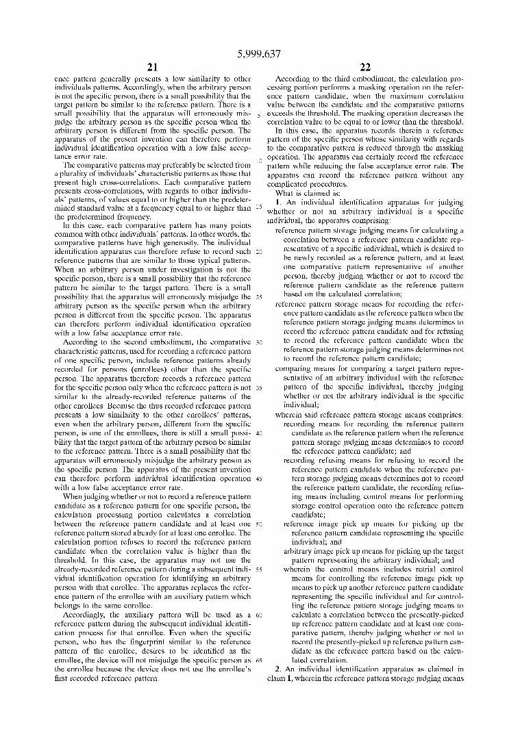
In order to attain the above object and other objects, the present invention provides an individual identi?cation appa ratus for judging Whether or not an arbitrary individual is a speci?c individual, the apparatus comprising: reference pat tern storage judging means for calculating a correlation betWeen a speci?c individual’s reference characteristic pat tern candidate, Which is desired to be neWly recorded as a reference pattern, and at least one comparative characteristic pattern of another person, thereby judging Whether or not to record the reference characteristic pattern candidate as the reference pattern based on the calculated correlation; refer ence pattern storage means for recording the reference characteristic pattern candidate as the reference pattern only When the reference pattern storage judging means deter mines to record the reference characteristic pattern candi date; and comparing means for comparing a target charac teristic pattern of an arbitrary individual With the reference pattern of the speci?c individual, thereby judging Whether or not the arbitrary individual is the speci?c individual.
According to another aspect, the present invention pro vides an individual identi?cation apparatus for determining Whether or not an arbitrary individual is a speci?c individual, the apparatus comprising: reference candidate reception means for receiving a predetermined characteristic pattern of a speci?c individual as a reference pattern can
5,999,637 3
didate; comparative pattern storage means for storing at least one corresponding characteristic pattern of at least one individual other than the speci?c individual as a comparative pattern; ?rst correlation calculating means for calculating a correlation betWeen the reference pattern candidate and the comparative pattern, thereby determining Whether or not to record the reference pattern candidate as a reference pattern; reference storage means for storing the reference pattern candidate as a reference pattern only When the ?rst corre lation calculating means determines to record the reference pattern candidate; target reception means for receiving, as a target pattern, a corresponding characteristic pattern of an arbitrary individual desired to be identi?ed as the speci?c individual; and second correlation calculating means for calculating a correlation betWeen the target pattern and the reference pattern, thereby judging Whether or not the arbi trary person is the speci?c individual.
According to still another aspect, the present invention provides an individual identi?cation apparatus for judging Whether or not an arbitrary individual is a speci?c individual, the apparatus comprising: correlation calculation means capable of calculating a correlation betWeen tWo patterns; reference candidate reception means for receiving a predetermined characteristic pattern of a speci?c indi vidual as a reference pattern candidate; reference storage judging means for controlling the correlation calculating means to calculate a correlation betWeen the reference pattern candidate and a comparative pattern, thereby deter mining Whether or not to record the reference pattern candidate, the comparative pattern including a correspond ing characteristic pattern of an individual other than the speci?c individual; reference storage means for recording the reference pattern candidate as a reference pattern only When the reference storage judging means determines to record the reference pattern candidate; target reception means for receiving a target pattern Which includes a cor responding characteristic pattern of an arbitrary individual desired to be identi?ed as the speci?c individual; and identi?cation Judging means for controlling the correlation calculating means to calculate a correlation betWeen the target pattern and the reference pattern, thereby judging Whether or not the arbitrary person is the speci?c individual.
According to a further aspect, the present invention pro vides a method of judging Whether or not an arbitrary individual is a speci?c individual, the method comprising the steps of: receiving a predetermined characteristic pattern of a speci?c individual as a reference pattern candidate; calculating a correlation betWeen the reference pattern can didate and a comparative pattern, thereby determining Whether or not to record the reference pattern candidate, the comparative pattern including a corresponding characteristic pattern of an individual other than the speci?c individual; recording the reference pattern candidate as a reference pattern only When the reference storage judging means determines to record the reference pattern candidate; receiv ing a target pattern Which includes a corresponding charac teristic pattern of an arbitrary individual desired to be identi?ed as the speci?c individual; and calculating a cor relation betWeen the target pattern and the reference pattern, thereby judging Whether or not the arbitrary person is the speci?c individual.
BRIEF DESCRIPTION OF THE DRAWINGS
The above and other objects, features and advantages of the invention Will become more apparent from reading the folloWing description of the preferred embodiment taken in connection With the accompanying draWings in which:
10
15
25
35
45
55
65
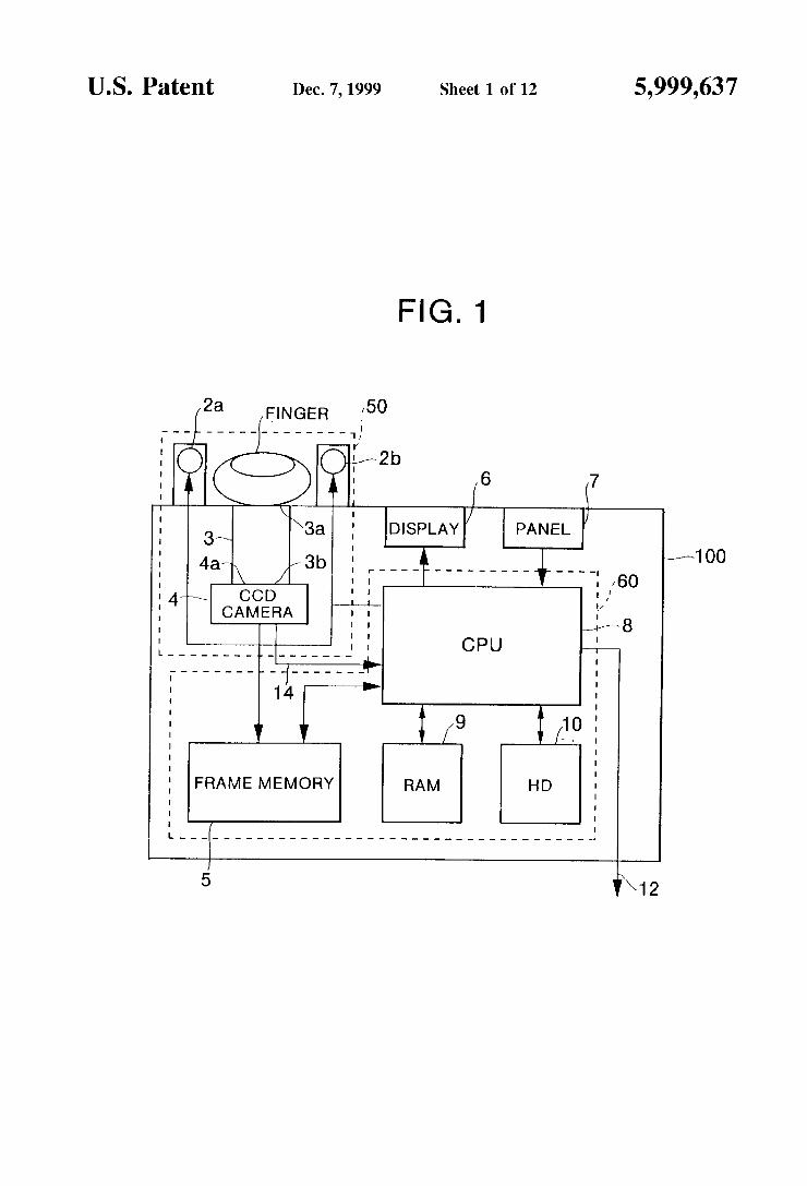
4 FIG. 1 shoWs a structure of a ?rst embodiment of the
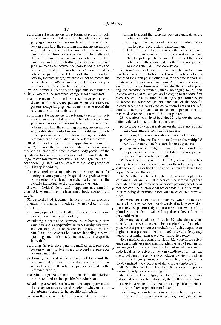
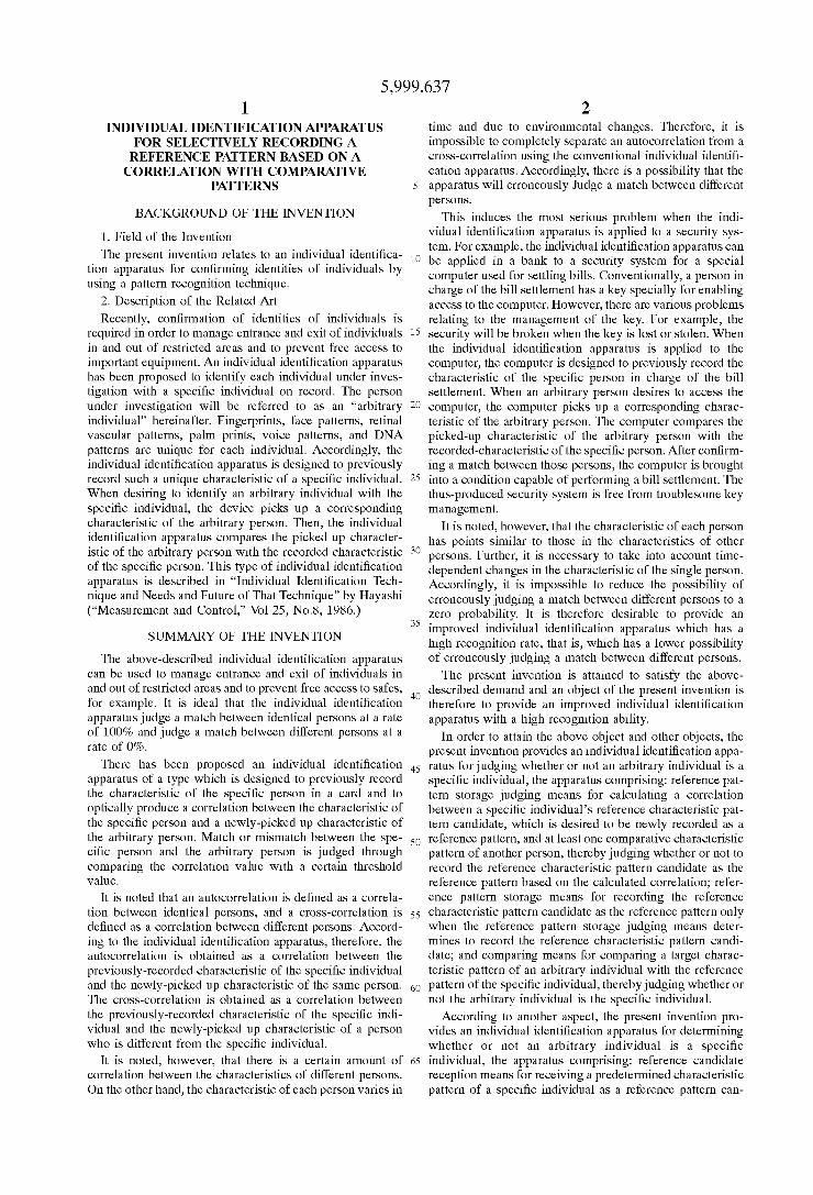
individual identi?cation apparatus of the present invention; FIG. 2 is a ?oWchart of a reference ?ngerprint recordation
process achieved by the individual identi?cation apparatus of FIG. 1;
FIG. 3 illustrates a correlation calculation employed in the recordation process of FIG. 2;
FIG. 4(A) shoWs an examination result of correlation values obtained betWeen one ?ngerprint A randomly selected from ?ve hundred ?ngerprints under investigation and 499 other ?ngerprints;
FIG. 4(B) shoWs an examination result of correlation values obtained betWeen one ?ngerprint B randomly selected from ?ve hundred ?ngerprints under investigation and 499 other ?ngerprints;
FIG. 4(C) shoWs an examination result of correlation values obtained betWeen one ?ngerprint C randomly selected from ?ve hundred ?ngerprints under investigation and 499 other ?ngerprints;
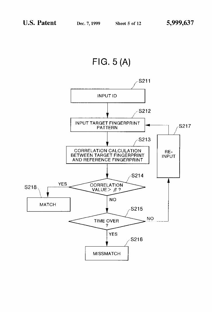
FIG. 5(A) shoWs a ?oWchart of an individual identi?ca tion process achieved by the individual identi?cation appa ratus of FIG. 1;
FIG. 5(B) illustrates a correlation calculation employed in the individual identi?cation process of FIG. 5(A);
FIG. 6(A) shoWs examination results of error recognition rates at Which a conventional individual identi?cation appa ratus recogniZed ?ngerprints of 600 individuals;
FIG. 6(B) shoWs an essential part of the examination results of the error recognition rates in a logarithm expres sion;
FIG. 7 illustrates one example of a masking operation subjected to a ?ngerprint;
FIG. 8(A) is a ?oWchart of a ?ngerprint recordation process in Which a reference ?ngerprint candidate is sub jected to a masking operation and then stored as a reference ?ngerprint;
FIG. 8(B) is a ?oWchart of a ?ngerprint recordation process in Which a reference ?ngerprint candidate is Fourier transformed, subjected to a masking operation, and then stored as a reference ?lter;
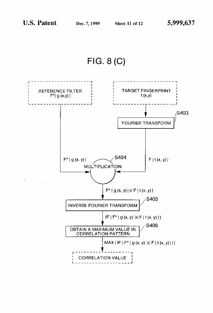
FIG. 8(C) illustrates a correlation calculation employed in the individual identi?cation process of FIG. 5(A) When the reference ?ngerprint is Fourier transformed before being stored as shoWn in FIG. 8(B);
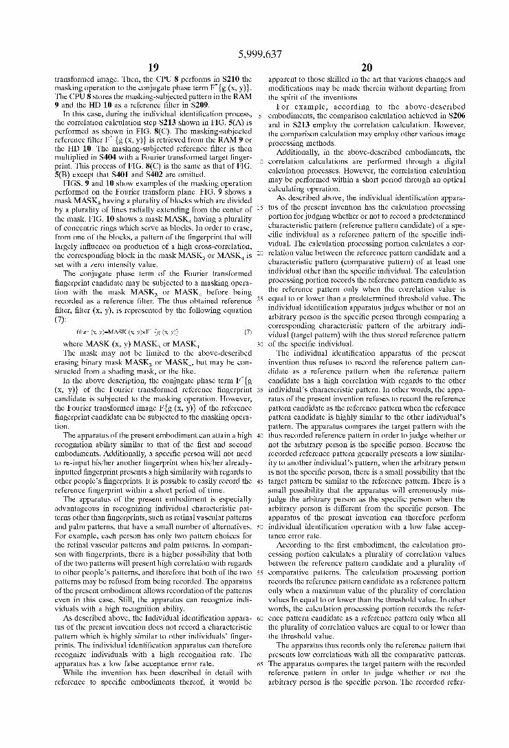
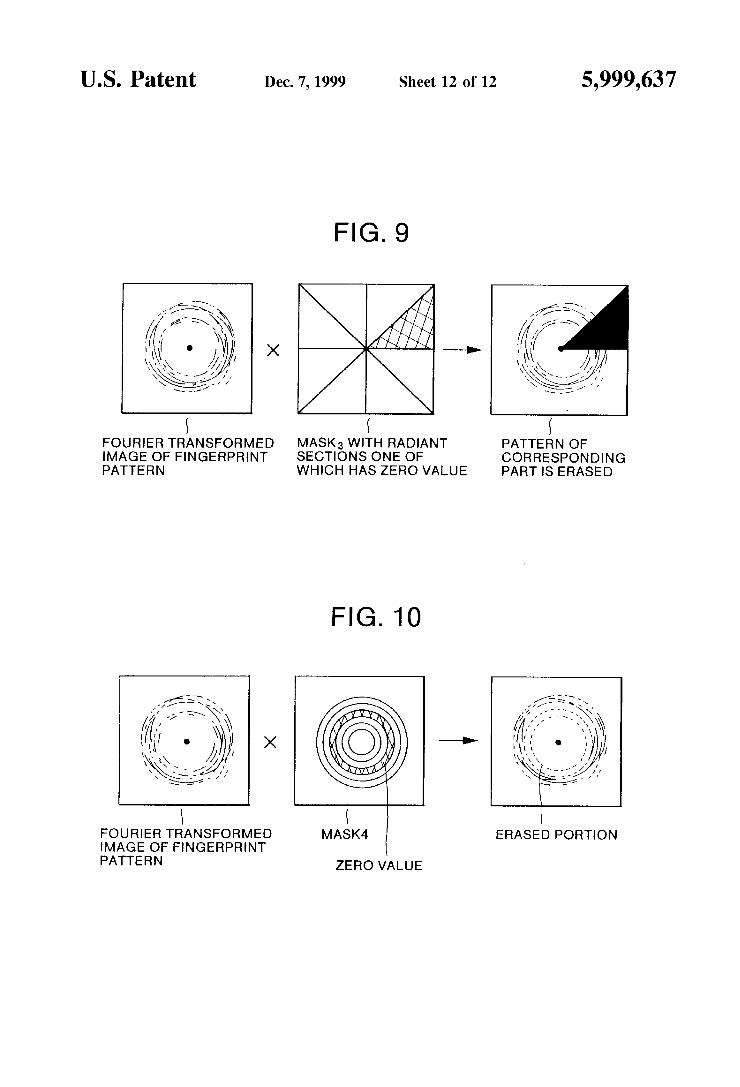
FIG. 9 illustrates one example of a masking operation subjected to a ?ngerprint on its Fourier transform plane; and
FIG. 10 illustrates another example of the masking opera tion subjected to a ?ngerprint on its Fourier transform plane.
DETAILED DESCRIPTION OF THE PREFERRED EMBODIMENTS
An individual identi?cation apparatus according to pre ferred embodiments of the present invention Will be described While referring to the accompanying draWings Wherein like parts and components are designated by the same reference numerals to avoid duplicating description. A ?rst embodiment of the individual identi?cation appa
ratus Will be described beloW With reference to FIGS. 1 through 6(B). The individual identi?cation apparatus of the ?rst
embodiment is for recogniZing identi?cations of individuals through comparing ?ngerprints (characteristic patterns) of the individuals. A ?ngerprint of a speci?c individual is previously recorded in the apparatus. When desiring to

5,999,637 5
con?rm Whether or not an arbitrary person, in access to the present apparatus, is the speci?c person, the apparatus picks up a ?ngerprint of the arbitrary person. Then, the apparatus compares the neWly-picked up ?ngerprint With the recorded ?ngerprint. Based on the compared result, the apparatus determines Whether or not the arbitrary person is the speci?c person. It is noted that the apparatus of the present invention can use various unique characteristic patterns other than ?ngerprints. That is, the apparatus can use patterns such as face patterns, palm prints, retinal vascular patterns, Holmant patterns in voices, and the like.
FIG. 1 shoWs a structure of the individual identi?cation apparatus 100 of the present embodiment. The apparatus 100 includes: an image pick up portion 50; a calculation pro cessing portion 60; a display portion 6; and an operation panel 7. The image pick up portion 50 is for inputting a ?ngerprint of an individual Who Wants to record his/her ?ngerprint in the apparatus. (This person Will be referred to as a “speci?c person,” hereinafter.) The image pick up portion 50 is also for inputting a ?ngerprint of an individual under investigation Who Wants to be identi?ed as the speci?c person. (This person Will be referred to as an “arbitrary person,” hereinafter.)
The calculation processing portion 60 is for judging Whether the inputted speci?c person’s ?ngerprint (referred to as a “reference ?ngerprint candidate”) is appropriate for a reference ?ngerprint. Based on an affirmative judgement, the calculation processing portion 60 records therein the reference ?ngerprint candidate as a reference ?ngerprint. The calculation processing portion 60 is also for comparing the inputted arbitrary person’s ?ngerprint (referred to as a “target ?ngerprint”) With the reference ?ngerprint of the speci?c individual. Based on the comparison results, the calculation processing portion 60 determines Whether the arbitrary person is the speci?c individual.
The display portion 6 is for shoWing a manual instruction and the judged results. The operation panel 7 includes several sWitches Which an operator manipulates to control the apparatus 100. For example, the operation panel 7 includes a numerical pad for designating a personal identi ?cation number (ID). The operation panel 7 also includes a mode setting key for setting one of a reference ?ngerprint storage mode and an individual identi?cation mode. The image pick up portion 50 includes: a pair of light emission diodes (LEDs) 2a and 2b, a ?ber optical plate (FOP) 3, and an charge-coupled device (CCD) camera 4. The calculation processing portion 60 includes: a frame memory 5, a CPU 8, a random access memory (RAM) 9, and a hard disk (HD) 10. The display portion 6 can be constructed from a liquid crystal display, an LED display, or the like.
The structure of the image pick up portion 50 Will be described beloW. The pair of LEDs 2a and 2b are light emitting elements for irradiating With light a ?nger of an individual to pick up his/her ?ngerprint. The FOP 3 is an integrated bundle of a plurality of optical ?bers. The FOP 3 has opposite end surfaces, that is, an input end surface 3a and an output end surface 3b along the longitudinal direc tions of the optical ?bers. The ?nger of the individual is placed on the input end surface 3a. The output end surface 3b is disposed in contact With a light receiving surface 4a of the CCD camera 4. The FOP 3 transmits the ?ngerprint from the input end surface 3a to the output end surface 3b. The CCD camera 4 is a tWo-dimensional image pick up element for picking up the ?ngerprint outputted from the output and surface.
The structure of the calculation processing portion 60 Will be described beloW. The frame memory 5, connected to the
10
15
25
35
45
55
65
6 CCD camera 4, serves as an image storage device for receiving image signals outputted from the CCD camera 4, for digitiZing the image (video) signals, and for storing the digitiZed image signals. During the reference ?ngerprint storage process, the frame memory 5 is inputted With image signals Indicative of a reference ?ngerprint candidate picked up from a speci?c person. The CPU 8 performs a reference ?ngerprint recordation or storage process, as Will be described later, to determine Whether the reference ?nger print candidate is appropriate for being stored as a reference ?ngerprint. During the individual identi?cation mode, on the other hand, the frame memory 5 is inputted With image signals indicative of a target ?ngerprint picked up from an arbitrary person. The CPU 8 performs an individual identi ?cation process, as Will also be described later, to con?rm Whether or not the arbitrary person is the speci?c person. That is, the CPU 8 performs comparing calculations onto the image signals stored in the frame memory 5 to produce a correlation value betWeen the target ?ngerprint and the reference ?ngerprint. Based on the magnitude of the obtained correlation value, the CPU 8 determines Whether the arbitrary person is the speci?c person. The CPU 8 is further for receiving instruction signals inputted from the operation panel 7 and for driving the LEDs 2a and 2b and controlling the display 6 to shoW the determined results. The RAM 9 and the HD 10 are for storing: the reference
?ngerprint of the speci?c Individual; an identi?cation num ber indicative of the speci?c individual; and judgement results. The HD 10 previously stores a plurality of compara tive ?ngerprints Which are used during the reference ?nger print storage process. The comparative ?ngerprints include siX hundred ?ngerprints obtained from randomly-selected siX hundred people. The HD 10 also previously stores various programs such as a program for performing the reference ?ngerprint storage process and a program for performing the individual identi?cation process.
According to the apparatus 100 With the above-described structure, a ?ngerprint of a speci?c individual is previously stored in the apparatus 100 through the reference ?ngerprint storage process. FIG. 2 shoWs the reference ?ngerprint storage process. When an arbitrary person desires to be identi?ed as the speci?c individual, the individual identi? cation process (recognition process) is conducted as shoWn in FIG. 5(A). With referring to FIG. 2, the reference ?ngerprint storage
process Will be described beloW. When a speci?c individual desires to neWly record his/her
?ngerprint in the apparatus 100, the speci?c individual manipulates the mode setting key on the panel 7 to designate the reference ?ngerprint storage mode. As a result, the CPU 8 starts performing the reference ?ngerprint storage process of FIG. 2. During this process, the speci?c individual ?rst manipulates in S201 the numeric pad in the operation panel 7 to designate his/her oWn identi?cation number. As a result, the LEDs 2a and 2b are turned ON, and the CCD camera 4 is turned ON. The display portion 6 is controlled to shoW a ?nger, such as a thumb, an indeX ?nger, or the like, Which has to be recorded in the apparatus 100. The speci?c individual then pushes doWn his/her ?nger of the instructed kind on the input end surface 3a as shoWn in FIG. 1. As a result, a ?ngerprint of the speci?c individual is picked up in S202. That is, a ?ngerprint of the speci?c individual is formed on the output end surface 3b of the FOP 3. The ?ngerprint is picked up by the CCD camera 4. The CCD camera 4 outputs, to the frame memory 5, video signals indicative of the speci?c individuals ?ngerprint. The CCD camera 4 also outputs a monitor signal 14 indicative of a

5,999,637 7
total intensity of the ?ngerprint. The CCD camera 4 applies the monitor signal 14 to the CPU 8.
In S203, the CPU 8 compares the total intensity of the ?ngerprint With a predetermined standard intensity. The CPU 8 determines, in S204, that the ?ngerprint is properly picked up only When the total intensity of the ?ngerprint eXceeds the standard intensity. In S204, the CPU 8 also judges a quality of the ?ngerprint based on the monitor signal 14. That is, the CPU 8 judges Whether or not the ?ngerprint has a suf?ciently high brightness, a suf?ciently large siZe, and the like. For eXample, the CPU 8 judges Whether or not the ?ngerprint is stable. The CPU 8 deter mines that the ?ngerprint is stable When the CCD’s picked up total intensity 14 remains higher than the standard value for a predetermined time period or more. When the CPU 8 determines that the quality of the ?ngerprint is insuf?cient, the CPU 8 controls in S205 the display portion 6 to shoW corresponding instruction comments. For example, the dis play portion 6 shoWs that “the inputted ?ngerprint is too thin,” “the inputted ?ngerprint is too small,” and “the inputted ?ngerprint is incorrectly positioned.” The speci?c person then again tries to input his/her ?ngerprint according to the instructions.
On the other hand, When the thus picked-up ?ngerprint has a suf?ciently high quality, the CPU 8 instructs in S206 the frame memory 5 to receive the ?ngerprint video signals as a reference ?ngerprint candidate. Then, the CPU 8 compares the reference ?ngerprint candidate With a plurality of comparative ?ngerprints Which are stored in the HD 10. As described already, the comparative ?ngerprints include siX hundred ?ngerprints of randomly-selected siX hundred people. In this example, the comparison calculation achieved in S206 employs a correlation calculation Which is high in speed and Which can properly separate the autocor relation from the cross-correlation.
A correlation degree, cr(u, v), betWeen the reference ?ngerprint candidate g(X, y) and each comparative ?nger print f(X, y) can be represented by the folloWing formula (1):
A correlation value is de?ned as a maXimum intensity of the correlation output indicated by or(u, v). This correlation value is free from positional shift betWeen the reference ?ngerprint candidate and the comparative ?ngerprint. The above-described correlation calculation is described in “Fourier Transform Employed in Optical Information Pro cessings” by Yatagai (“Optics,” Vol. 21, No.6).
The above-described correlation calculation (1) can be reWritten by tWo stages of Fourier transform operation as shoWn beloW.
Where IF, F indicate inverse Fourier transformation and Fourier transformation, respectively. The “F*{g}” indicates a phase term of a conjugate of “F{g}.”
In vieW of the above, the correlation calculation of S206 is performed as shoWn in FIG. 3. That is, the reference ?ngerprint candidate g(X, y) is ?rst Fourier transformed into F{g(X, y)} in S301. Then, in S302, a conjugate of the Fourier transform is obtained, and a phase term of the conjugate, F* {g (X, y)}, is obtained. Similarly, in S303, one comparative ?ngerprint f(X, y) is retrieved from the HD 10 and Fourier transformed into F {f (X, Then, in S304, those images F* {g (X, y)} and F {f (X, y)} are multiplied. The product is
10
15
25
35
45
55
65
8 inverse Fourier transformed in S305, As a result, a correla tion pattern is obtained. Then, a maXimum value of the correlation pattern is calculated as a correlation value C in S306. During the above-described course of processes
S301—S306, the correlation value C is obtained betWeen the reference ?ngerprint candidate g (X, y) and the retrieved one comparative ?ngerprint f (X, y). This course of processes S301—S306 is repeatedly performed for the reference ?n gerprint candidate g(X, y) and the siX hundred comparative ?ngerprints f (X, y).
Thus, the CPU 8 obtains in S206 siX hundred correlation values C betWeen the one reference ?ngerprint candidate and the siX hundred comparative ?ngerprints. Then, the CPU 8 determines a maXimum value M of the siX hundred correlation values C. Then, in S207, the CPU 8 compares the maXimum correlation value M With a predetermined cross correlation acceptable value (Which Will be referred to as a threshold 0t hereinafter.) The individual identi?cation apparatus of the present
embodiment employs this correlation comparison steps in S206 and S207 for the reasons set forth beloW. The present inventors performed investigations on ?nger
prints. The investigation results shoW that individuals have tWo types of ?ngerprints: a ?rst type shoWing a high cross-correlation With a number of other people’s ?nger prints: and a second type shoWing a loW cross-correlation With most other people’s ?ngerprints. In other Words, the ?rst type of ?ngerprint has characteristics common With a number of other people’s ?ngerprints. The second type of ?ngerprints are unusually formed and so do not have char acteristics in common With those of other people’s ?nger prints. The same person can have ?rst type of ?ngerprints on one or more ?ngers and second type ?ngerprints on the remaining ?nger.
FIGS. 4(A) through 4(C) are cross-correlation value his tograms for three different ?ngerprints A, B, and C Which Were randomly selected from ?ve hundred ?ngerprints under investigation. FIG. 4(A) is a histogram shoWing hoW cross correlations, betWeen the ?ngerprint A and other 499 ?ngerprints, are distributed. FIG. 4(B) is a histogram shoW ing hoW cross-correlations, betWeen the ?ngerprint B and other 499 ?ngerprints, are distributed. FIG. 4(C) is a histo gram shoWing hoW cross-correlations, betWeen the ?nger print C and other 499 ?ngerprints, are distributed. In each graph, a horiZontal aXis denotes correlation values “X”, and a vertical aXis denotes a frequency “F” at Which the corre sponding correlation values “X” are obtained. It is noted that a frequency value is de?ned as the total frequency at Which correlation values X that satisfy the folloWing inequal ity are obtained:
“ 1, Where n is an integer equal to or higher than 0. A correlation detector (CCD detector) used in these
investigations Was designed so as to be capable of outputting a correlation value of 255 at maXimum. The dark level of the correlation detector appeared at the correlation value of 18 in each graph and presented a highest frequency level. As apparent from FIGS. 4(A)—4(C), though the ?ngerprint
A presented a maXimum cross-correlation value of 23, the ?ngerprint C presented a maXimum cross-correlation value of 41. Thus, distribution in the correlation values are Widely changed in accordance With the respective ?ngerprints. Because the ?ngerprint C has many points similar to those of other people’s ?ngerprints, the ?ngerprint C is inappro priate as a reference ?ngerprint for discriminating the person
5,999,637 9
having the ?ngerprint C from other people. Contrarily, the ?ngerprint A has the smallest number of points similar to those of other people’s ?ngerprints, and therefore is most appropriate as a reference ?ngerprint for discriminating a person having the is ?ngerprint A from other people.
In vieW of the above-described investigation results, the comparison processes of S206 and S207 are provided according to the present invention. In other Words, the comparison processes are provided in order not to record such a ?ngerprint C as presents a high cross-correlation With regards to other people’s ?ngerprints. In the process of S206, the reference ?ngerprint candidate is compared With the six hundred comparative ?ngerprints, that is, six hundred ?ngerprints of other people. When the maximum value M, of the six hundred correlation values C, betWeen the refer ence ?ngerprint candidate and the six hundred comparative ?ngerprints, exceeds the threshold 0t, then the CPU 8 determines that this reference ?ngerprint candidate is highly similar to other people’s ?ngerprints, and therefore is inap propriate for a reference ?ngerprint. The CPU 8 therefore refuses to record the reference ?ngerprint candidate.
In this case, the CPU 8 controls in S208 the display portion 6 to shoW an instruction that the speci?c person should change his/her ?nger for inputting a reference ?n gerprint. For example, the CPU 8 controls the display portion 6 to shoW “the inputted ?ngerprint is inappropriate for recordation,” “use another ?nger,” and the like. After revieWing this instruction, the speci?c individual retries to input another ?ngerprint in S202. On the other hand, When the maximum value M of the
correlation values C is equal to or loWer than the threshold ot, the CPU 8 determines that the reference ?ngerprint candidate is not similar to the other people’s ?ngerprints and therefore is appropriate for a reference ?ngerprint. The CPU 8 therefore records in S209 the reference ?ngerprint candi date into the RAM 9 and the HD 10 as a reference ?nger print. Each of the RAM 9 and the HD 10 stores the reference ?ngerprint together With the already-inputted identi?cation number. Thus, a recordation of the speci?c individual’s ?ngerprint is completed. The CPU 8 controls the display portion 6 to shoW that the recordation is completed.
In the above description, the CPU B compares, With the threshold ot, the maximum value M of all the correlation values C. HoWever, the reference ?ngerprint storage pro gram may be designed to perform this comparing operation Without calculating the maximum value M but in the fol loWing manner (1), (2), or the like.
(1) The correlation values C betWeen the reference ?n gerprint candidate and the comparative ?ngerprints are compared one by one With the threshold 0t. The recordation of the reference ?ngerprint candidate is rejected When one correlation value C appears exceeding the threshold 0t.
(2) All the correlation values C are compared With the threshold 0t. The number of correlation values C that exceed the threshold 0t is counted. The recordation of the candidate is rejected When the counted number exceeds a predeter mined number.
The speci?c person may store one or more auxiliary reference ?ngerprints in addition to the reference ?ngerprint. The auxiliary reference ?ngerprints Will be used When the speci?c person injures or otherWise changes a ?nger to be used during the individual identi?cation process. Also in order to record the auxiliary reference ?ngerprints, the CPU 8 may calculate correlation values betWeen the auxiliary ?ngerprints and the comparative ?ngerprints. The CPU 8 may compare the correlation values or their maximum values With the threshold 0t in the same manner as described
10
15
25
35
45
55
65
10 above. The CPU 8 may use the compared results to deter mine Whether the auxiliary reference ?ngerprints can be recorded.
Next, the individual identi?cation process achieved by the apparatus 100 Will be described With reference to FIG. 5(A). An arbitrary person, Who Wants to be identi?ed as the
speci?c individual, manipulates the mode setting key on the panel 7 to designate the individual identi?cation mode. As a result, the CPU 8 starts performing the individual identi? cation process of FIG. 5(A). During this process, the arbi trary person ?rst inputs the identi?cation number of the speci?c individual in S211. The CPU 8 retrieves, from the RAM 9 or the HD 10, a reference ?ngerprint Which is recorded in correspondence With the inputted identi?cation number. The CPU 8 controls the display 6 to shoW a kind of the retrieved ?ngerprint, such as an index ?nger, a thumb, or the like. The arbitrary person pushes doWn his/her ?nger of the instructed kind onto the input end surface of the POP 3. Then, in S212, the arbitrary person’s ?ngerprint (a target ?ngerprint) is picked up by the CCD camera 4, and trans ferred to the frame memory 5.
Next, the CPU 8 performs a comparison calculation in S213 to compare the presently-picked up target ?ngerprint With the retrieved reference ?ngerprint. The CPU 8 performs the correlation operation in S213 as shoWn in FIG. 5(B). That is, the reference ?ngerprint g(x, y) is ?rst Fourier transformed into F{g(x, y)} in S401. Then, in S402, a conjugate of the Fourier transform is obtained, and a phase term of the conjugate, F* {g (x, y)}, is obtained. Similarly, in S403, the target ?ngerprint t(x, y) is Fourier transformed into F {t (x, Then, in S404, those images F* {g (x, y)} and F {t (x, y)} are multiplied. The product is inverse Fourier transformed in S405. As a result, a correlation pattern is obtained. Then, a maximum value of the correla tion pattern is calculated as a correlation value in S406.
Then, the CPU 8 compares in S214 the obtained corre lation value With a predetermined threshold [3. When the correlation value is equal to or loWer than the threshold [3, the CPU 8 compares in S215 the number of already performed trial processes With a predetermined limit num ber. It is noted that one trial process is de?ned in the series of steps of S212 through S214. When the number of the already-performed trials is equal to or loWer than the pre determined limit number, the CPU 8 controls in S217 the display 6 to instruct the arbitrary person to retry to input his/her ?ngerprint. After revieWing the instruction, the arbi trary person Will again input his/her ?ngerprint in S212. As a result, a subsequent trial is performed through S212 through S214. On the other hand, When the number of the already
performed trials exceeds the limit number, the CPU 8 determines that time is over and therefore determines in S216 that the arbitrary person is different from the speci?c individual. The CPU 8 then controls the display 6 to shoW that the arbitrary person is not the speci?c individual. The CPU a may sound a buZZer (not shoWn) before ?naliZing the program.
Similarly at a cash dispenser machine employed in banks, When the above-described series of steps S211—S216 is conducted three successive times for the single inputted identi?cation number and When each ends With a negative result, the CPU 8 may stop using the reference ?ngerprint Which is recorded in correspondence With that identi?cation number. When one or more auxiliary reference ?ngerprints are recorded in correspondence With the identi?cation number, the CPU may replace the reference ?ngerprint With the auxiliary reference ?ngerprint. A system manager of the

5,999,637 11
apparatus 100 may perform various processes following such a negative judgement. For example, the system man ager may request the speci?c person to again record his/her ?ngerprint to reneW the reference ?ngerprints On the other hand, When the correlation value exceeds the
threshold [3, the CPU 8 determines in S218 that the arbitrary person is the speci?c individual. The CPU 8 outputs a match recognition signal 12 to an external device Which is con nected to the present device 100. For example, the external device is an electromagnetic-locked door. The match rec ognition signal 12 serves as a lock release signal for causing the electromagnetic look to open. When the external device is a usage-management device for important equipment, the match recognition signal 12 serves as a usage alloWance signal for setting the equipment into a condition usable by the arbitrary person. Thus, the individual identi?cation pro cess is completed.
In the present embodiment, the reference ?ngerprint is recorded in each of the RAM and HD as it is. The reference ?ngerprint is therefore Fourier transformed in S401 during the individual identi?cation process. HoWever, the reference ?ngerprint storage program of FIG. 2 may be designed to Fourier transform the reference ?ngerprint and then to store the Fourier transformed ?ngerprint (reference ?lter) into the RAM 9 and the HD 10 in S209. In this case, the CPU 8 Will not need to Fourier transform the reference ?ngerprint during the individual identi?cation process. In other Words, the step S401 may be omitted from the individual identi? cation process. As described above, the individual identi?cation appara
tus 100 of the present embodiment refuses to record a ?ngerprint Which presents a high correlation in regards to the comparative ?ngerprints, that is, Which presents high similarity to other people’s ?ngerprints. The apparatus 100 records, as reference ?ngerprints, only those ?ngerprints that have a loW correlation With regards to all the comparative ?ngerprints. Accordingly, even When the threshold [3 is set to a value equal to a conventionally-used threshold, it is still possible to reduce the probability of erroneously identifying, as the speci?c person, an arbitrary person Who is different from the speci?c person. In other Words, it is possible to decrease a false acceptance error rate for erroneously -judging a match betWeen different persons. It is noted that by setting the threshold [3 to a value less than the conventionally-used threshold, it is possible to reduce the probability of an erroneous rejection When the arbitrary person is the speci?c person. In other Words, it is possible to decrease a false rejection error rate for erroneously judging a mismatch betWeen identical persons. According to the present invention, still in this case, it is possible to decrease or at least to prevent an increase in the false acceptance error rate.
This advantage of the present invention Will be apparent from results of investigations Which Were performed by the present inventors With using a conventional individual iden ti?cation apparatus. The investigations Will be described beloW.
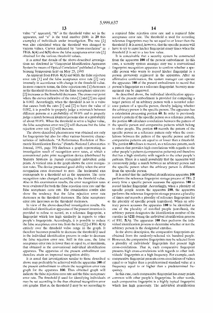
The present inventors investigated recognition error rates, at Which the conventional individual identi?cation apparatus identi?ed nix hundred individuals through subjecting their ?ngerprints to a conventional correlation calculation. FIG. 6(A) shoWs the investigation results, and FIG. 6(B) enlarges an essential part of FIG. 6(A). FIG. 6(B) shoWs the recog nition error rates in a logarithm expression.
During the investigations, the present inventors examined tWo types of error recognition rates: [1] the false rejection error rate, that is, the probability of erroneously judging a
10
15
25
35
45
55
65
12 mismatch betWeen identical persons; and [2] the false accep tance error rate, that is, the probability of erroneously judging a match betWeen different persons. In order to examine the false rejection error rate [1], one person Was caused to input four times a ?ngerprint of his/her oWn one ?nger. Out of the thus obtained four ?ngerprints, the most stable ?ngerprint Was recorded as a reference ?ngerprint. Then, autocorrelations betWeen the reference ?ngerprint and the remaining three ?ngerprints Were calculated. As a result, three correlation values Were obtained. Then, a maximum value of the three correlation values Was calculated. The maximum value Was then compared With a predetermined threshold. When the maximum value Was higher than the threshold, the conventional individual identi?cation appara tus properly judged that the three ?ngerprints belong to the person Who has the reference ?ngerprint. On the other hand, When the maximum value Was equal to or loWer than the threshold, the apparatus erroneously judged that the three ?ngerprints belong to a person Who is different from the person Who has the reference ?ngerprint. Based on this theory, the present inventors controlled the conventional individual identi?cation apparatus to perform the above described correlation calculation for six hundred Individu als. The present inventors then counted the number of individuals, for Whom the maximum autocorrelation values became equal to or loWer than the threshold. Thus, the
present inventors obtained the false rejection error rate This error rate ErrACP is represented by the folloWing
formula (3):
h
f ACP(x)dx ErrA CP = of
(3)
n
“ 1, Where x is a correlation value (correlation calculation result), “ACP(x)” is a frequency at Which the correlation value “x” appeared, “th” is a threshold value set in the apparatus, and “n” is the total number (600, in this example) of individuals under investigation. The false rejection error rate [1] Was calculated for the threshold being changed to various values. Curves indicated by “Autocorrelation” in FIGS. 6(A) and 6(B) shoW the false rejection error rate [1] obtained for the various threshold values.
In order to examine the false acceptance error rate [2], on the other hand, the present Inventors controlled the conven tional individual identi?cation apparatus to perform corre lation calculations on tWo different persons several times and to obtain several correlation values. Then, the present inventors controlled the apparatus to calculate the maximum value of the correlation values. The apparatus compared the maximum correlation value With the threshold value. When the maximum correlation value Was higher than the threshold, the apparatus erroneously judged that the tWo different persons Were identical. The present inventors con trolled the apparatus to perform this correlation calculations on 600x599 couples of different persons. The present inven tors counted the number of correlation maximum values that exceeded the threshold, thereby calculating the false accep tance error rate The false acceptance error rate ErrCCP is represented by the folloWing formula (4):
(4)
ErrCCP :
<< 1, Where x is a correlation value (correlation calculation result), “CCP(x)” is a frequency at Which the correlation