58838112 Ewm Welding Book
104
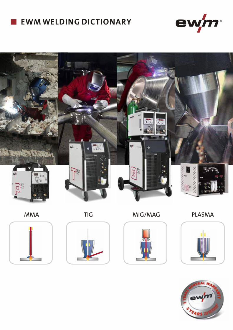
EWM WELDING DICTIONARY MMA MIG/MAG PLASMA TIG
-
Upload
prabhakar-kattula -
Category
Documents
-
view
110 -
download
1
Transcript of 58838112 Ewm Welding Book
www.ewm-group.comwww.ewm-tv.de
Sales, Consulting, Service
For more information please visit our website at
EWM
WEL
DIN
G D
ICTI
ON
AR
YM
MA
•
MIG
/MA
G •
PLA
SMA
• T
IG
EWM WELDING DICTIONARY
EW
M H
IGH
TEC
WEL
DIN
G G
mbH
200
9©
·
W
M.0
551.
01 ·
10.
2009
· W
e re
serv
e th
e rig
ht to
mak
e am
endm
ents
MMA MIG/MAG PLASMATIG
EWM HIGHTEC WELDING GmbH Dr. Günter-Henle-Straße 856271 Mündersbach GermanyTel: +49 2680 181-0 · Fax: -244 www.ewm-group.com · [email protected]
EWM SCHWEISSTECHNIK-HANDELS-GmbHIn der Florinskaul 14-16 56218 Mülheim-Kärlich · GermanyTel: +49 261 988898-0 · Fax: -20www.ewm-group.com/handel · [email protected]
EWM HIGHTEC WELDING GmbHBranch NorthLindenstraße 1a 38723 Seesen-Rhüden · GermanyTel: +49 5384 90798-0 · Fax: -20www.ewm-group.com/handel · [email protected]
EWM HIGHTEC WELDING SALES s.r.o.Prodejní a poradenské centrum Tyršova 2106 256 01 Benešov u Prahy · Czech RepublicTel: +420 317 729-517 · Fax: -712www.ewm-group.com/cz · [email protected]
EWM HIGHTEC WELDING GmbHScharnsteinerstraße 154810 Gmunden · AustriaTel: +43 7612 778 02-0 · Fax: -20www.ewm-group.com/at · [email protected]
EWM HIGHTEC WELDING FZCORegional Office Middle EastJAFZA View 18 F 14 05 · P.O. Box 262851 Jebel Ali Free Zone · Dubai · United Arab EmiratesTel: +971 4 8857-789 · Fax: -500www.ewm-group.com/me · [email protected]
EWM SCHWEISSTECHNIK-HANDELS-GmbHSachsstraße 28 50259 Pulheim · GermanyTel: +49 2234 697-047 · Fax: -048www.ewm-group.com/handel · [email protected]
EWM HIGHTEC WELDING s.r.o.Tr. 9. kvetna 718 / 31 407 53 Jiříkov · Czech RepublicTel: +420 412 358-551 · Fax: -20www.ewm-group.com/cz · [email protected]
EWM HIGHTEC WELDING UK Ltd.Unit 2B Coopies Way Coopies Lane Industrial EstateMorpeth · Northumberland · NE 61 6JT · Great BritainTel: +44 1670 505875 · Fax: -514305www.ewm-group.com/uk · [email protected]
EWM HIGHTEC WELDING (Kunshan) Ltd.10 Yuanshan Road, Kunshan New & High-tech Industry Development ZoneKunshan · Jiangsu · 215300 · People´s Republic of ChinaTel: +86 512 57867-188 · Fax: -182www.ewm-group.com/cn · [email protected]

The Reason Behind the “EWM Total System Concept”.
Compromising on the quality of welding equipment doesn‘t pay long-term. Many of our customers found this out for themselves before choosing to place their trust in EWM. Rectifying welding errors is costly. Outmoded processes may create extra work, while hidden quality defects lead to unhappy customers and regress claims. Downtime due to machine failure is also expensive.
For this reason, we offer our customers a fully coordinated system where all components are systematically geared towards delivering consistently high welding quality, conserving resources and reducing the amount of work involved.
Points to consider when calculating the costs for the perfect weld bead.EWM quality will save you money. You will benefit from extended service life, reduced down times, reduced process costs and a reduced consumption of gas and filler materials.

Welding processes designed and patented by EWM such as:
or
make it possible to handle welding tasks that were previously impossible.
Here highly dynamic voltage, current and wire values need to be transported to the welding arc without electrical loss or distortion, in some cases across large distances. It is easy to understand that only perfectly optimised transfer elements such as:■ Intermediate hose packages■ Wire feed systems■ Welding torch systems
can achieve the best possible results with regard to:■ Minimal spatter■ Gap bridging■ Reduction in welding faults■ Reduction in post weld work■ Reduced distortion of the welded material■ Reduced consumption of materials, gas and energy■ Reduced consumption of wearing parts/consumables
and therefore maximum cost savings.
The Reason Behind the “EWM Total System Concept”. Because Quality Saves You Money.
EWM develops and produces welding machines, wire feed units, torch systems and intermediate hose packages of the highest quality, offering you the maximum benefit when it comes to your welding tasks.
coldArc®
forceArc®
activArc®
spotArc® Focustig®
in conjunction with pulse welding for MIG/MAG applications
in conjunction with cold/hot wire for TIG applications

MMA PRIMER


The EWM MMA Primer
EWM HIGHTEC WELDING GmbH Dr. Günter-Henle-Str. 8, D-56271 Mündersbach/Ww., Germany www.ewm.de
1 10.09
Contents
1 Preface ..............................................................................................................................................................2
2 The process.......................................................................................................................................................2
2.1 General remarks .....................................................................................................................................2 2.2 Current type ............................................................................................................................................2 2.3 Electrode types .......................................................................................................................................3 2.4 Properties of the coating types ...............................................................................................................4
3 Which electrode for what purpose.....................................................................................................................5
3.1 Welding-engineering considerations when choosing stick electrodes....................................................5 3.2 Material considerations when choosing stick electrodes........................................................................6
4 Groove preparation ...........................................................................................................................................7
4.1 Groove shapes........................................................................................................................................7 4.2 Placement of the weld groove side walls................................................................................................9
5 Electrode holders and welding cables...............................................................................................................9
6 Power sources...................................................................................................................................................9
6.1 Power source designs...........................................................................................................................10 6.2 Special functions with inverters for MMA welding.................................................................................12
7 Performing welding work.................................................................................................................................12
7.1 Igniting the arc.......................................................................................................................................12 7.2 Moving the electrode.............................................................................................................................13 7.3 Magnetic arc blow .................................................................................................................................13 7.4 Set welding parameters ........................................................................................................................13
8 Work safety .....................................................................................................................................................14
9 Special notes for MMA welding on different materials ....................................................................................15
9.1 Unalloyed and low-alloy steels..............................................................................................................16 9.2 High-alloy steels and nickel-based alloys .............................................................................................16 9.3 GMA-surfacing ......................................................................................................................................17
10 Applications for MMA welding .........................................................................................................................17
10.1 Example applications ............................................................................................................................17
11 Literature .........................................................................................................................................................18
12 Imprint .............................................................................................................................................................18

The EWM MMA Primer
EWM HIGHTEC WELDING GmbH Dr. Günter-Henle-Str. 8, D-56271 Mündersbach/Ww., Germany www.ewm.de
2 10.09
1 Preface Manual metal arc welding, known as MMA welding for short, is one of the old-est welding processes still in use today. It goes back to research carried out by Slawjanow who in 1891 was the first to use a metal rod that was simultaneously the arc carrier and the welding additive, rather than the standard carbon electrode that had been used for arc welding up un-til that point. The first stick electrodes were not coated and were therefore diffi-cult to weld with. Later on the electrodes were coated with materials that made welding easier, protected the weld metal and had a metallurgic affect on the proc-ess. The first patent for a coated stick electrode was created in 1908. Elec-trodes can be coated by dipping or by pressing on an extruder press. Today only electrodes with extruded coatings are used. MMA welding is characterised by a rela-tively low level of investment and an uni-versal application. The process can be used for a wide range of materials and ensures high-quality weld seams. In re-cent times, however, MMA welding has been superseded, frequently for eco-nomic reasons, by other welding tech-niques that can be mechanised. This primer clarifies the special features of this process and provides information on the correct application of the tech-nique.
2 The process 2.1 General remarks
MMA welding (process number 111) is a fusion welding process, and more pre-cisely, a metal arc welding process. ISO 857-1 (1998 edition) describes the weld-ing processes in this group as follows: Metal arc welding: Arc welding process using an electrode used up during the procedure. Metal arc welding without gas shielding: Metal arc welding process without the addition of external shielding gas and
Manual metal arc welding: Metal arc welding performed manually using a coated electrode. In Germany the last process mentioned is known as manual arc welding or MMA welding for short, and is characterised by the arc arcing between a melting elec-trode and the molten bath (Figure 1). There is no external protection; any pro-tection against the atmosphere comes from the electrode. In this case the elec-trode is both the arc carrier and the weld-ing additive. The coating forms slag and/or shielding gas, which among other things protects the drop being transferred and protects the molten pool against the ingress of the atmospheric gases oxygen nitrogen and hydrogen.
2.2 Current type For manual arc welding (MMA welding), both d.c. and a.c. can in principle be used, but not all types of stick electrode coatings can be welded on sinusoidal a.c., e.g. not pure basic electrodes. When welding with d.c., the minus pole is gen-erally connected to the electrode and the plus pole to the workpiece with most elec-trode types. Basic electrodes are an ex-ception to this. They are better welded on the plus pole. The same applies to certain manufacturers of cellulose electrodes. More information on this can be found in section 2.3 Electrode types.
1 Workpiece 5 Coated electrode 2 Weld seam 6 Electrode holder 3 Slag 7 Power source 4 Arc
Figure 1 Scheme of manual metal arc weld-ing irrespective to ISO 857-1

The EWM MMA Primer
EWM HIGHTEC WELDING GmbH Dr. Günter-Henle-Str. 8 D-56271 Mündersbach/Ww., Germany www.ewm.de
3 10.09
The electrode is the welder's tool. The welder moves the arc burning on the electrode in the weld groove side walls, thus melting the edges of the groove (Figure 2). Different current intensities are required depending on the type of groove and the thickness of the parent material. The stick electrodes are available in different di-ameters and lengths, since their diameter and length determine the current loading possible. Table 1 shows the standardised dimensions as specified in DIN EN 759. Higher welding currents can be used with larger core wire diameters.
2.3 Electrode types There are stick electrodes with coatings of very different compositions. The com-position of the coating determines the melt characteristics of the electrode, its welding properties and the quality of the weld metal. Irrespective to DIN EN 499 the coating types given in Table 2 exist for stick electrodes for welding unalloyed steels. A distinction is drawn here between sin-gle-material types and mixed types. Let-ters are used to designate the different types of electrode. The letters stand for the following: C=cellulose, A=acid,
R=rutile and B=basic. In Germany the ru-tile type plays a leading role. Stick elec-trode may be thin-coated, medium-coated or thick-coated. With rutile electrodes, which are available as standard in all three coating thicknesses, the thick-coated electrodes are therefore known as RR for clearer identification. With alloyed and high-alloy stick elec-trodes, there is no such variety in the types of coating. With stick electrodes for welding stainless steels, which are stan-dardised in DIN EN 1600, a distinction is only made between rutile electrodes and basic types, for example, as with stick electrodes for welding creep resistant steels (DIN EN 1599), but in this case there are only basic mixed types, as with the rutile electrodes, although this is not specifically marked. This is the case with electrodes that have better welding char-acteristics in out-of-position welding, for example. Stick electrodes for welding high-tensile steels (DIN EN 757) are only available with basic coatings.
1 Weld groove side walls 4 Molten slag 2 Stick electrode 5 Solidified slag3 Molten weld metal
Figure 2 Position of the electrode in the weld groove side walls
Table 1 Diameter and lengths of stick elec-trodes conforming to DIN EN 759 Electrodes
Nom
inal
dia
-m
eter
in m
m
Per
mis
sibl
e de
viat
ion
Nom
inal
le
ngth
in m
m
Per
mis
sibl
e de
viat
ion
1.6 2.0 2.5
0.06 200 to
350 3
3.2 4.0 5.0 6.0
0.10 350 to
450 3
Type Coating A acid C cellulose R rutile RR thick rutile RC rutile cellulose RA rutile acid RB rutile basic B basic
Table 2 Coating types to DIN EN 499

The EWM MMA Primer
EWM HIGHTEC WELDING GmbH Dr. Günter-Henle-Str. 8 D-56271 Mündersbach/Ww., Germany www.ewm.de
4 10.09
2.4 Properties of the coating types The composition and the thickness of the coating have a significant effect on the welding characteristics. This relates both to the stability of the arc and to the mate-rial transition during welding and the vis-cosity of slag and molten bath. The size of the drop being transferred in the arc is of particular significance. Figure 3 shows a scheme diagram of the drop transferin the four basic types of coatings [1]. The cellulose type (Figure 3, c) has a medium- to large-drop material transfer. The coating consists primarily of organic components that burn in the arc, thus forming shielding gas to protect the welding position. As the coating contains only small quantities of arc-stabilising ma-terials with the exception of cellulose and other organic materials, virtually no slag is produced. Cellulose types are espe-cially well suited to vertical-down welding (Figure 4, vertical-down position) be-cause there is no need to worry about slag formation. The acid type (A), where the coating con-sists primarily of iron ore and manganese iron ore, provides the arc atmosphere with greater quantities of oxygen. The weld metal also takes this up, thus reduc-ing the surface tension. The conse-
quences are a very fine, spray-type mate-rial transfer and a fluid weld metal. Elec-trodes of this type are not therefore suit-able for out-of-position welding. The arc is also very "hot-running"; it permits high welding speeds, but tends towards the formation of undercuts. The disadvan-tages described have meant that pure acid type stick electrodes are now barely used in Germany. The rutile acid type (RA), a mixture of the acid and the rutile electrode, has instead taken its place. The electrode also has the corresponding welding properties. The coating of the rutile type (R/RR) con-sists primarily of titanium oxide in the form of the minerals rutile (TiO2) or ilmen-ite (TiO2
. FeO) or even artificial titanium oxide. Electrodes of this type are charac-terised by a fine- to medium-sized drop material transfer, quiet, low-spatter melt-ing off, very fine seam formation, good slag removability and good re-ignition characteristics. The latter is only ob-served in this form with rutile electrodes with a high proportion of TiO2 in the coat-ing. It means that with an electrode which has already meltdown, re-ignition is pos-sible without removing the coating crater (Figure 5) [2]. The slag film formed in the crater has vir-tually the conductivity of a semicon-ductor, if it has a sufficiently high TiO2 content, which means that when the edge of the crater is placed on the workpiece, enough current flows for the arc to be
a)
b)
c)
d)
a) Cellulose type c) Acid type b) Rutile type d) Basic type
Figure 3 Material transition with dif-ferent coating types [1]
PA
PB
PG
PF
PE
PD
PC
Figure 4 Welding positions to ISO 6947

The EWM MMA Primer
EWM HIGHTEC WELDING GmbH Dr. Günter-Henle-Str. 8 D-56271 Mündersbach/Ww., Germany www.ewm.de
5 10.09
able to ignite without the core wire touch-ing the workpiece. A spontaneous re-ignition of this type is always important if the welding process is being frequently interrupted, e.g. with short seams. In addition to the pure rutile type, there are several mixed types in this group of electrodes. Of particular note is the rutile-cellulose type (RC) in which part of the rutile has been replaced with cellulose. As cellulose combusts during welding, less slag is produced. This type can therefore also be used for vertical-down welding (vertical-down position). How-ever, it also has good welding character-istics in most other positions. Another mixed type is the rutile/basic type (RB). It also has a slightly thinner coating than the RR type. This and its special slag characteristics make it especially useful for welding in the vertical up position. There only remains the basic type (B). In this case the coating consists primarily of basic oxides of calcium (CaO) and mag-nesium (MgO), to which fluorspar (CaF2) has been added as a slag thinner. The fluorspar impairs a.c. weldability in higher proportions. Pure basic electrodes cannot be welded on sinusoid a.c. current, but there are also mixed types with less fluorspar in the coating that can be used with this type of current. The material transfer of basic electrodes uses me-dium- to large-drops and the molten pool is viscous. The electrode has good weld-ing properties in all positions. However,
the beads produced are slightly rein-forced and more roughly rippled due to the higher viscosity of the weld metal. The weld metal has very good toughness properties. Basic coatings are hygro-scopic. Care must therefore be taken that the electrode are stored especially care-fully in a dry location. Electrodes that have become damp must be oven-dried. However, when the electrodes are welded dry, the weld metal has a very low hydrogen content. In addition to stick electrodes with normal efficiency (<105%), other stick electrodes have, thanks to iron powder added across the coating, an higher efficiency, generally >160%. These electrodes are known as iron powder types or high-efficiency electrodes. Thanks to their high desposition efficiency, they can be used more efficiently for many applications than normal electrodes, but their use is normally restricted to vertical (flat posi-tion) and horizontal positions (horizontal vertical position).
3 Which electrode for what purpose When choosing stick electrodes, material and welding-engineering considerations need to be taken into account.
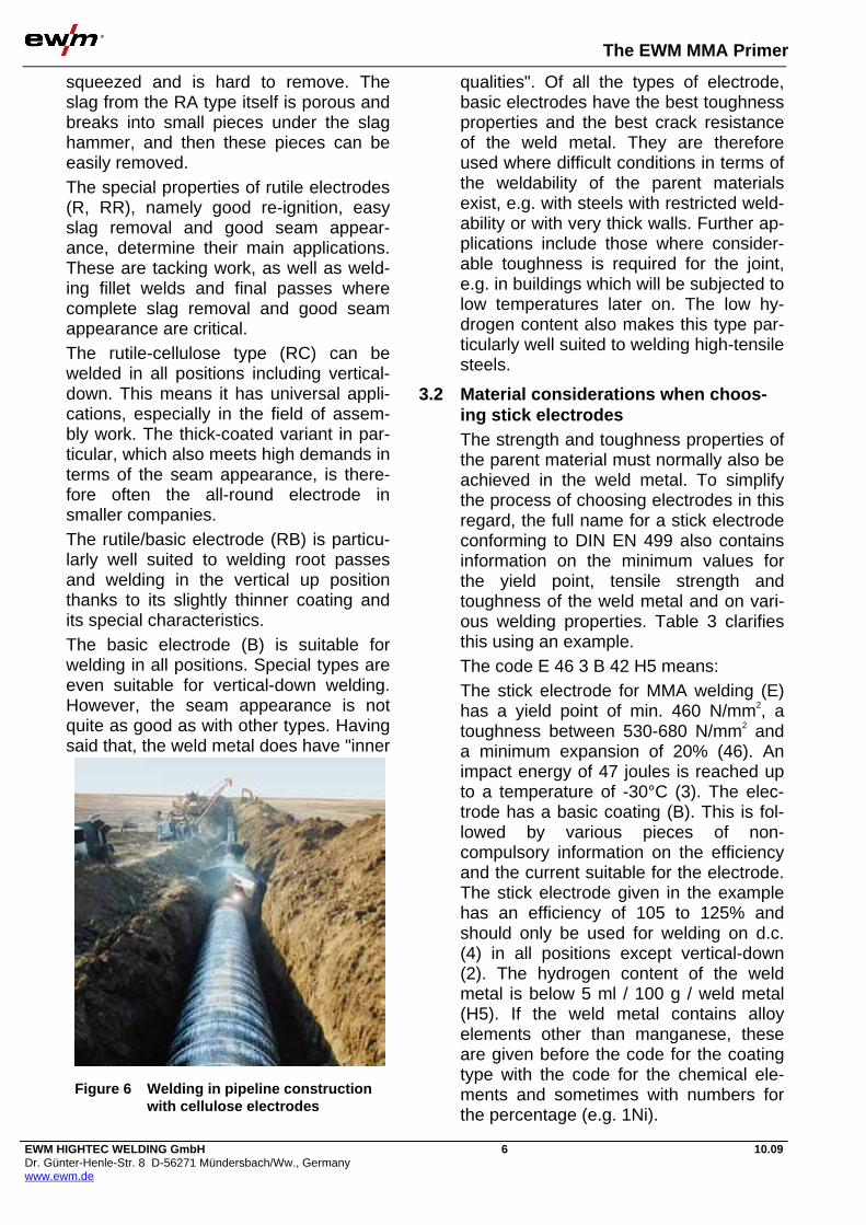
3.1 Welding-engineering considerations when choosing stick electrodes Each type of electrode has highly specific welding properties and is therefore also used for highly specific welding tasks. Thanks to its suitability for vertical-down welding (vertical down position), cellulose electrodes (C) are used for welding cir-cumferentially seams on tubes with larger diameters. The preferred application here is for laying pipelines (Figure 6). In comparison with welding in the vertical up position (vertical up position), rela-tively thick electrodes (4 mm) can be used here for the root pass. This makes for increased efficiency. The particular advantage of the mixed ru-tile/acid type (RA) is the slag residue in narrow grooves, where compact slag is
a)
b)
c)
d)
a) Core wire c) Slag film in coating crater b) Coating d) Workpiece
Figure 5 Re-ignition of the coating crater
The EWM MMA Primer
EWM HIGHTEC WELDING GmbH Dr. Günter-Henle-Str. 8 D-56271 Mündersbach/Ww., Germany www.ewm.de
6 10.09
squeezed and is hard to remove. The slag from the RA type itself is porous and breaks into small pieces under the slag hammer, and then these pieces can be easily removed. The special properties of rutile electrodes (R, RR), namely good re-ignition, easy slag removal and good seam appear-ance, determine their main applications. These are tacking work, as well as weld-ing fillet welds and final passes where complete slag removal and good seam appearance are critical. The rutile-cellulose type (RC) can be welded in all positions including vertical-down. This means it has universal appli-cations, especially in the field of assem-bly work. The thick-coated variant in par-ticular, which also meets high demands in terms of the seam appearance, is there-fore often the all-round electrode in smaller companies. The rutile/basic electrode (RB) is particu-larly well suited to welding root passes and welding in the vertical up position thanks to its slightly thinner coating and its special characteristics. The basic electrode (B) is suitable for welding in all positions. Special types are even suitable for vertical-down welding. However, the seam appearance is not quite as good as with other types. Having said that, the weld metal does have "inner
qualities". Of all the types of electrode, basic electrodes have the best toughness properties and the best crack resistance of the weld metal. They are therefore used where difficult conditions in terms of the weldability of the parent materials exist, e.g. with steels with restricted weld-ability or with very thick walls. Further ap-plications include those where consider-able toughness is required for the joint, e.g. in buildings which will be subjected to low temperatures later on. The low hy-drogen content also makes this type par-ticularly well suited to welding high-tensile steels.
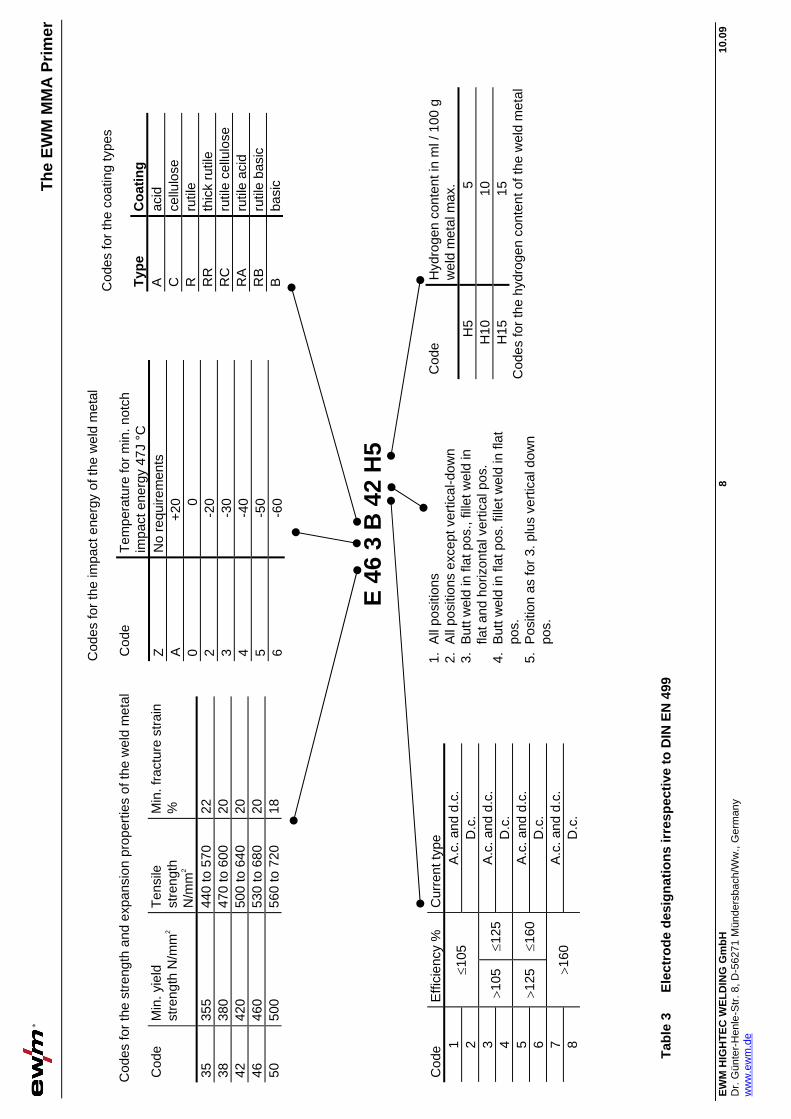
3.2 Material considerations when choos-ing stick electrodes The strength and toughness properties of the parent material must normally also be achieved in the weld metal. To simplify the process of choosing electrodes in this regard, the full name for a stick electrode conforming to DIN EN 499 also contains information on the minimum values for the yield point, tensile strength and toughness of the weld metal and on vari-ous welding properties. Table 3 clarifies this using an example. The code E 46 3 B 42 H5 means: The stick electrode for MMA welding (E) has a yield point of min. 460 N/mm2, a toughness between 530-680 N/mm2 and a minimum expansion of 20% (46). An impact energy of 47 joules is reached up to a temperature of -30°C (3). The elec-trode has a basic coating (B). This is fol-lowed by various pieces of non-compulsory information on the efficiency and the current suitable for the electrode. The stick electrode given in the example has an efficiency of 105 to 125% and should only be used for welding on d.c. (4) in all positions except vertical-down (2). The hydrogen content of the weld metal is below 5 ml / 100 g / weld metal (H5). If the weld metal contains alloy elements other than manganese, these are given before the code for the coating type with the code for the chemical ele-ments and sometimes with numbers for the percentage (e.g. 1Ni).
Figure 6 Welding in pipeline construction with cellulose electrodes

The EWM MMA Primer
EWM HIGHTEC WELDING GmbH Dr. Günter-Henle-Str. 8 D-56271 Mündersbach/Ww., Germany www.ewm.de
7 10.09
A low hydrogen content is important when welding steel with a tendency to-wards hydrogen-induced crack formation, such as high-tensile steel. The code for the hydrogen content provides the nec-essary information here. Similar identification systems also exist for high-tensile electrodes (DIN EN 757), creep resistant electrodes (DIN EN 1599) and for stainless electrodes (DIN EN 1600). For creep resistant and stainless electrodes, however, both the strength properties and the creep resistance and corrosion properties of the weld metals must match those of the parent metals. The general rule here is therefore that the weld metal should ideally be the same type or higher-alloy than the parent metal.
4 Groove preparation 4.1 Groove shapes
Figure 7 shows the most important groove shapes used in MMA welding. For square grooves, the root must be grooved out from the rear side for larger sheet thicknesses. In order to avoid faults, the same applies to welding with backing runs and to welding on both sides of double-V butt seam and double-V butt seams with root faces for larger sheet thicknesses. With single-V butt seams and single-bevel butt seams, the root phase can also be broken slightly; the root face thickness in single-V butt seams with broad root face is determined by the current intensity that can be ap-plied. For economic reasons, single-U butt seams and double-U butt seams are used primarily for larger wall thicknesses because the weld volume to be applied is lower than with single-V butt, single-V butt with broad root face, double-V butt and double-V butt with root face welds due to the smaller opening angle. With fillet welds, the gap between the two joining members should be kept as small as possible so that no slag can penetrate the gap. This applies in particular to T-seams, lap seams and fillet welds.
Joint type Workpiece thickness (mm)
Diagram
Butt weld One side 3-8 both sides <8
Single-V butt weld
One side 3-10 with backing runs 3-40
Single-V butt weld with broad root face
One side 5-40 with backing runs >10
Double-V butt weld
Both sides > 10
Single-U butt weld
One side > 12 with backing runs >12
Single-V butt weld
One side 3-10 with s.u. 3-30
Fillet weld T-joint
One side >2
Fillet weld -corner joint
One side >2 Both sides > 3
Fillet weld - lap joint
One side >2
Fillet weld –double fillet weld
Both sides > 2
Figure 7 Groove shapes irrespective to DIN EN 29692-ISO 9692
Th
e E
WM
MM
A P
rim
er
EW
M H
IGH
TE
C W
EL
DIN
G G
mb
H
Dr.
Gün
ter-
Hen
le-S
tr. 8
, D-5
6271
Mün
ders
bach
/Ww
., G
erm
any
ww
w.e
wm
.de
8 10
.09
Tab
le 3
E
lect
rod
e d
esig
nat
ion
s ir
resp
ecti
ve t
o D
IN E
N 4
99
Cod
es fo
r th
e st
reng
th a
nd e
xpan
sion
pro
pert
ies
of th
e w
eld
met
al
Cod
e M
in. y
ield
st
reng
th N
/mm
2 T
ensi
le
stre
ngth
N
/mm
2
Min
. fra
ctur
e st
rain
%
35
355
440
to 5
70
22
38
380
470
to 6
00
20
42
420
500
to 6
40
20
46
460
530
to 6
80
20
50
500
560
to 7
20
18
Cod
es fo
r th
e im
pact
ene
rgy
of th
e w
eld
met
al
Cod
e T
empe
ratu
re fo
r m
in. n
otch
im
pact
ene
rgy
47J
°C
Z
No
requ
irem
ents
A
+
20
0 0
2 -2
0 3
-30
4 -4
0 5
-50
6 -6
0
Cod
es fo
r th
e co
atin
g ty
pes
Typ
e C
oat
ing
A
ac
id
C
cellu
lose
R
ru
tile
RR
th
ick
rutil
e R
C
rutil
e ce
llulo
se
RA
ru
tile
acid
R
B
rutil
e ba
sic
B
basi
c
Cod
e H
ydro
gen
cont
ent i
n m
l / 1
00 g
w
eld
met
al m
ax.
H5
5 H
10
10
H15
15
C
odes
for
the
hydr
ogen
con
tent
of t
he w
eld
met
al
1.
All
posi
tions
2.
A
ll po
sitio
ns e
xcep
t ver
tical
-dow
n 3.
B
utt w
eld
in fl
at p
os.,
fille
t wel
d in
fla
t and
hor
izon
tal v
ertic
al p
os.
4.
But
t wel
d in
flat
pos
. fill
et w
eld
in fl
at
pos.
5.
P
ositi
on a
s fo
r 3.
plu
s ve
rtic
al d
own
pos.
Cod
e E
ffici
ency
%
Cur
rent
type
1
A.c
. and
d.c
. 2
105
D
.c.
3 A
.c. a
nd d
.c.
4 1
05
125
D
.c.
5 A
.c. a
nd d
.c.
6 1
25
160
D
.c.
7 A
.c. a
nd d
.c.
8 1
60
D.c
.
E 4
6 3
B 4
2 H
5

The EWM MMA Primer
EWM HIGHTEC WELDING GmbH Dr. Günter-Henle-Str. 8 D-56271 Mündersbach/Ww., Germany www.ewm.de
9 10.09
4.2 Placement of the weld groove side walls The groove edges are normally bevelled by oxyacetylene cutting for unalloyed and low-alloy steels. High-alloy steels and metals that can be MMA welded, can be fusion cut using a plasma arc. It is not absolutely necessary to remove the oxide skin produced by thermal cutting, but may be required in special cases. If there are special requirements in terms of observing low tolerances, mechanical undercutting of the edges of parts to be joined may be recommended. This ap-plies to circumferential welds in particular. The modern options for cutting with an electron or a laser beam are more com-monly available in automated production and are the exception rather than the rule with MMA welding.
5 Electrode holders and welding cables Figure 8 shows the current course in the welding current circuit. The electrode is connected to one pole of the current source via the electrode holder (Figure 9) and the welding cable. The other pole is connected to the work-piece via the workpiece lead and the workpiece clamp. The electrode holder is available in differ-ent sizes depending on the electrode di-ameter being used and the current inten-sity being applied. They were previously standardised into 5 sizes in Germany in DIN 8569, Part 1. In Europe DIN EN 60974, Part 11, covers them. The cross-section and the length of the leads must be such that the voltage drop
does not exceed certain values due to its resistance. Irrespective to the VDE stan-dard, this is 2 volts up to 200 amperes and 5 volts up to 500 amperes. When calculating the necessary lead cross-section, the lengths of the welding lead and the workpiece lead should be added. Standard lead cross-sections for MMA welding are 25, 35, 50 and 70 mm2 de-pending on the current intensity being applied.
6 Power sources The power source converts the high mains voltage to the main lower welding voltage and supplies the high current in-tensities required for welding which the mains cannot provide. It is also possible to set and control the current. Both a.c. and d.c. can be used for welding. Direct Power sources are general pur-pose because not all stick electrode types are weldable on sinusoid a.c.– see also the Current type section. Power sources
Electrode holder
Power source
Workpiece clamp
WorkpieceArc
Stick electrode(core rod + coating)
= or ~
- (+)
+ (-)
Figure 8 The power circuit [2]
Figure 9 Example of an electrode holder
Figure 10 EWM power source PICO 162

The EWM MMA Primer
EWM HIGHTEC WELDING GmbH Dr. Günter-Henle-Str. 8 D-56271 Mündersbach/Ww., Germany www.ewm.de
10 10.09
for MMA welding have a falling, static characteristic, and with conventional power sources (such as for the PICO 162, Figure 10) generally continuously falling and with electronic power sources falling vertically in the work area (Figure 11). This ensures that with the unavoidable changes in length of the arc with MMA welding, the most important parameter for the quality of the welding connection – the current intensity – is changed only slightly or not at all.
6.1 Power source designs The simplest way to convert mains cur-rent into welding current is by means of the welding transformer. It converts the current only in terms of the current inten-sity and voltage (transformer) and sup-plies sinusoid a.c. for welding. The trans-former principle is shown in Figure 12 [2].
With power line-fed networks, the trans-former is single-phase connected be-tween one phase and the outer conductor or between two phases of the three-phase network. Different current intensi-ties can be set via scattering kernel ad-justment, primary side turn tapping or via transducer. With the welding rectifier the current is rectified after transformation by diodes or thyristors, i.e. d.c. current is available for welding. For basic welding rectifiers, the transformer is single-phase or two-phase connected, but with more demanding machines, connected three-phase to all phases of the three-phase network. The latter supplies a very even current without significant current ripples. The evenness of the current is particularly useful when welding with basic electrodes and when welding with metal alloys, such as nickel-based alloys. With simple machines the welding recti-fier is set in the transformer – see Setting the welding transformer. Modern welding rectifiers are set using thyristors, which are controllable rectifiers, using phase shift control. Electronic power sources (inverters) are also increasingly being used for MMA welding in practise (Figure 13). Figure 14 shows the block diagram of a 3rd generation inverter with a clock fre-quency of up to 100 kHz. These Power sources have a completely different layout to conventional power sources. The current coming from the mains is first rectified and then "hacked"
U [V]
I [A]
a)
100A 200A 300A
b)
a) Continually falling characteristic
b) Vertically falling characteristic (constant current characteristic)
Figure 11 Characteristics for MMA welding
Iron core
Primarycircetmain~
Magneticflux
Secondarycurcetweldingcurcet~
Figure 12 Transformer principle [2]
Figure 13 EWM power source STICK 350
The EWM MMA Primer
EWM HIGHTEC WELDING GmbH Dr. Günter-Henle-Str. 8 D-56271 Mündersbach/Ww., Germany www.ewm.de
11 10.09
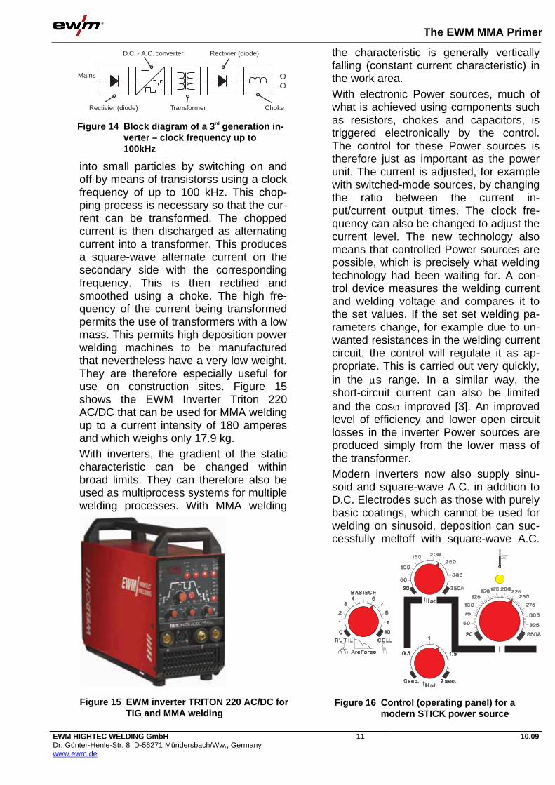
into small particles by switching on and off by means of transistorss using a clock frequency of up to 100 kHz. This chop-ping process is necessary so that the cur-rent can be transformed. The chopped current is then discharged as alternating current into a transformer. This produces a square-wave alternate current on the secondary side with the corresponding frequency. This is then rectified and smoothed using a choke. The high fre-quency of the current being transformed permits the use of transformers with a low mass. This permits high deposition power welding machines to be manufactured that nevertheless have a very low weight. They are therefore especially useful for use on construction sites. Figure 15 shows the EWM Inverter Triton 220 AC/DC that can be used for MMA welding up to a current intensity of 180 amperes and which weighs only 17.9 kg. With inverters, the gradient of the static characteristic can be changed within broad limits. They can therefore also be used as multiprocess systems for multiple welding processes. With MMA welding
the characteristic is generally vertically falling (constant current characteristic) in the work area. With electronic Power sources, much of what is achieved using components such as resistors, chokes and capacitors, is triggered electronically by the control. The control for these Power sources is therefore just as important as the power unit. The current is adjusted, for example with switched-mode sources, by changing the ratio between the current in-put/current output times. The clock fre-quency can also be changed to adjust the current level. The new technology also means that controlled Power sources are possible, which is precisely what welding technology had been waiting for. A con-trol device measures the welding current and welding voltage and compares it to the set values. If the set set welding pa-rameters change, for example due to un-wanted resistances in the welding current circuit, the control will regulate it as ap-propriate. This is carried out very quickly, in the s range. In a similar way, the short-circuit current can also be limited and the cos improved [3]. An improved level of efficiency and lower open circuit losses in the inverter Power sources are produced simply from the lower mass of the transformer. Modern inverters now also supply sinu-soid and square-wave A.C. in addition to D.C. Electrodes such as those with purely basic coatings, which cannot be used for welding on sinusoid, deposition can suc-cessfully meltoff with square-wave A.C.
D.C. - A.C. converter Rectivier (diode)
Rectivier (diode)
Mains
Transformer Choke
Figure 14 Block diagram of a 3rd generation in-verter – clock frequency up to 100kHz
Figure 15 EWM inverter TRITON 220 AC/DC for TIG and MMA welding
Figure 16 Control (operating panel) for a modern STICK power source

The EWM MMA Primer
EWM HIGHTEC WELDING GmbH Dr. Günter-Henle-Str. 8 D-56271 Mündersbach/Ww., Germany www.ewm.de
12 10.09
This may be necessary if undesirable magnetic arc blow conditions exist.
6.2 Special functions with inverters for MMA welding Modern inverter Power sources also offer a range of special functions, which sim-plify welding and make the process safer [4]. This is how the arc force is set (Figure 16). For example, if the arc voltage becomes too short due to a large drop forming on the electrode, and drops to below 8 volts, the current intensity is automatically in-creased (Figure 17). This means that the arc can burn freely once more and does not go out. This function is particularly important when welding using cellulose-coated elec-trodes, as well as those with basic coat-ings. The width of the arc and thus the arc hardness can be infinity adjusted using an adjustable choke. A hard arc is advan-tageous for difficult magnetic arc blow conditions exist, for example. The Hotstart function used ensures safe ignition of the arc and sufficient warm-up of the cold parent material at the start of welding. The ignition process is carried out at an increased current intensity (Figure 18). The Antistick function prevents the elec-trode annealing if the ignition process fails and the electrode "sticks" to the workpiece. The warning up of the elec-trode caused by the resistance heating may damage the coating until it breaks
off. With Power sources equipped with the relevant function, the current is im-mediately regulated down to few amperes if the voltage does not rise after the igni-tion short-circuit. The electrode can then be removed from the ignition point very easily.
7 Performing welding work The welder requires good training, not just in terms of skills, but also in terms of the relevant specialist knowledge in order to avoid errors. The training guidelines from the DVS – Deutscher Verband für Schweißen und verwandte Verfahren e.V. (German Association for Welding and Re-lated Procedures) are recognised world-wide and have now been adopted by the International Institute of Welding (IIW). Before starting welding, the workpieces are generally tack-welded. The tack points must be long and thick enough to ensure that the workpieces cannot con-tract to a non-permissible extent during welding and that the tack points do not break.
7.1 Igniting the arc The welding process is initiated by con-tact ignition with MMA welding. To close the power circuit, a short-circuit needs to be created between the electrode and the workpiece first and the electrode raised slightly immediately afterwards; the arc will ignite. The ignition process should never take place outside the groove, but only at points that will be fused again im-
U [V]
U krit.
R B C I [A]
Figure 17 Principle for setting the arc force R= rutile electrode; B= basic electrode; C= cellulose electrode
I [A]
t
a)
b) a) Hotstart current
b) Hotstart time
Figure 18 Principle of the “Hotstart” function
The EWM MMA Primer
EWM HIGHTEC WELDING GmbH Dr. Günter-Henle-Str. 8 D-56271 Mündersbach/Ww., Germany www.ewm.de
13 10.09
mediately once the arc is burning. This is because at ignition points where this does not occur, cracks may occur in suitably sensitive materials due to the sudden heating. When using basic electrodes with a ten-dency to initial porosity, the ignition proc-ess must actually take place significantly before the start of the weld. The arc is then moved back to the starting point for the seam and during the course of the welding process the first drops deposited, which are generally porous, will be fused once more.
7.2 Moving the electrode The electrode is positioned vertically or at a slight slant to the panel surface. It is ti-tled slightly in the direction of welding. The visible arc length, i.e. the distance between the edge of the crater and the workpiece surface should be roughly equal to the core wire diameter. Basic electrodes must be welded with a very short arc (distance=0.5 x core wire di-ameter). To ensure this, they need to be held in a more steeply inclined position than rutile electrodes. In most positions, stringer beads are welded or a slight weaving movement is used with an increasingly large groove width. Only in the vertical up position are weave beads drawn across the entire width of the groove. Welding is normally carried out with the torch directed at the finished part of the joint; only in the verti-cal up position is forehand welding used with the electrode.
7.3 Magnetic arc blow Arc blow is where the arc being diverted from its central axis lengthens and a hissing noise is emitted as a result. This diversion could result in discontinuities, such as the fusion penetration becoming inadequate and, in slag-forming welding processes, slag inclusions being pro-duced in the seam due to the slag flowing ahead of the molten pool. Forces arising from the surrounding magnetic field cause the diversion. Just like any other current-carrying conductor,
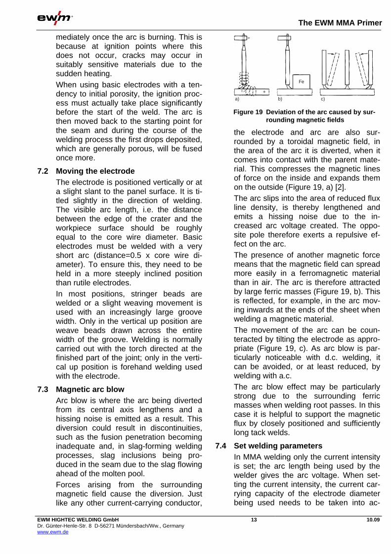
the electrode and arc are also sur-rounded by a toroidal magnetic field, in the area of the arc it is diverted, when it comes into contact with the parent mate-rial. This compresses the magnetic lines of force on the inside and expands them on the outside (Figure 19, a) [2]. The arc slips into the area of reduced flux line density, is thereby lengthened and emits a hissing noise due to the in-creased arc voltage created. The oppo-site pole therefore exerts a repulsive ef-fect on the arc. The presence of another magnetic force means that the magnetic field can spread more easily in a ferromagnetic material than in air. The arc is therefore attracted by large ferric masses (Figure 19, b). This is reflected, for example, in the arc mov-ing inwards at the ends of the sheet when welding a magnetic material. The movement of the arc can be coun-teracted by tilting the electrode as appro-priate (Figure 19, c). As arc blow is par-ticularly noticeable with d.c. welding, it can be avoided, or at least reduced, by welding with a.c. The arc blow effect may be particularly strong due to the surrounding ferric masses when welding root passes. In this case it is helpful to support the magnetic flux by closely positioned and sufficiently long tack welds.
7.4 Set welding parameters In MMA welding only the current intensity is set; the arc length being used by the welder gives the arc voltage. When set-ting the current intensity, the current car-rying capacity of the electrode diameter being used needs to be taken into ac-
a) b) c)
Fe
+
Figure 19 Deviation of the arc caused by sur-rounding magnetic fields

The EWM MMA Primer
EWM HIGHTEC WELDING GmbH Dr. Günter-Henle-Str. 8 D-56271 Mündersbach/Ww., Germany www.ewm.de
14 10.09
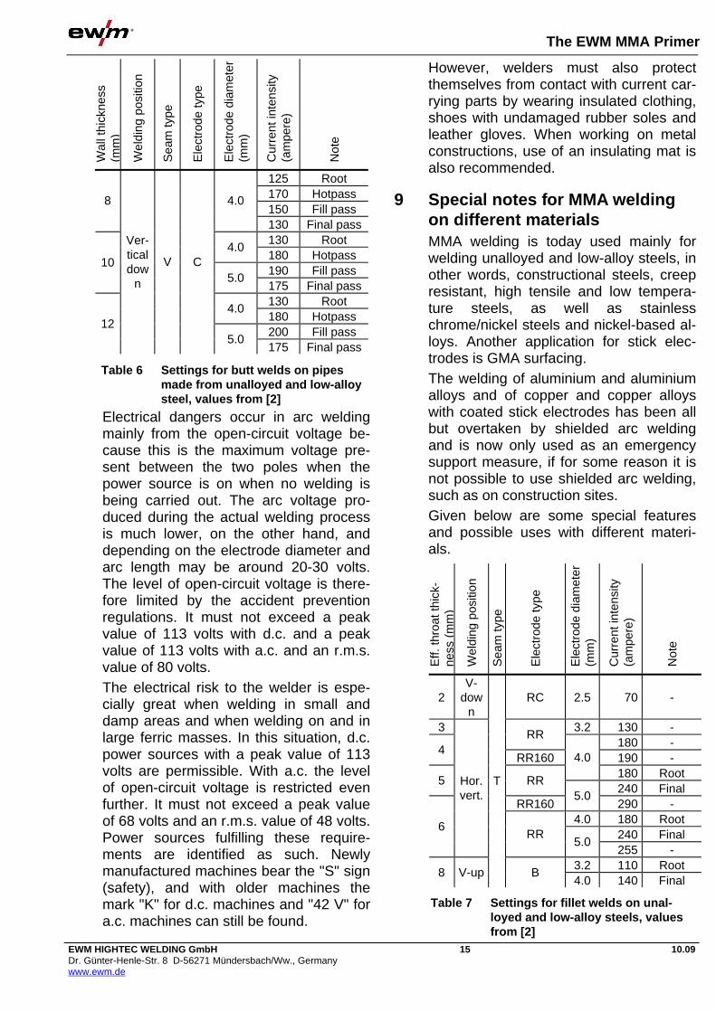
count. Table 4 provides guideline values for the current carrying capacity for the various electrode diameters. The rule which can be used here is that lower limit values are used for welding root passes and for the vertical up posi-tion, and the upper values apply to all other positions and for intermediate and final passes. As the current intensities in-crease, the melt deposition power in-creases and therefore also the welding speed. The fusion penetration also in-creases with increasing current levels. The current intensities given only apply to unalloyed and low-alloy steels. With high-alloy steels and nickel-based materials, lower values should be set due to the greater electrical resistance of the core wire. Settings for various welding tasks are given in Table 5, Table 6 and Table 7, [2], [5].
8 Work safety In MMA welding, risks to the welder arise from the smoke and gases of the stick electrode coatings and from metal va-pour, as well as from visible and ultravio-let rays and infrared radiation emitted by the arc; electrical risks are also present. Irrespective to current accident preven-tion regulations, an extraction system is required directly at the point of emission for MMA welding at fixed workstations. Only for short-term and mobile welding is air ventilation or a welding-engineering ventilation device permissible in certain circumstances.
The beam from the arc dazzles eyes and may cause "arc eye", i.e. an eye inflam-mation. However, the beam can also cause skin burns and symptoms similar to sunburn. Welders must therefore pro-tect themselves using suitable work clothing and a welding safety shield with the relevant safety filters conforming to EN 166 and EN 169. The safety filters to be used should be of protection level 9 – for thin electrodes and low current inten-sities up to 14 – for thick electrodes and high current intensities. A plain cover glass in front of the safety filters or a pair of clear glasses protect against eye inju-ries from slag breaking.
Diameter (d in mm)
Length (l in mm)
Current intensity (I in A)
Rule of thumb for current in-tensity in A
2.0 250/300 40... 80 2.5 350 50...100
20...40 x d
3.2 350/400 90...150 4.0 350/400 120...200 5.0 450 180...270
30...50 x d
6.0 450 220...360 35...60 x d
Table 4 Current intensities irrespective to the electrode diameter
Table 5 Settings for butt welds on unalloyed and low-alloy sheet materials, val-ues from [2] and [5]
She
et th
ickn
ess
(mm
)
Wel
ding
pos
ition
Sea
m ty
pe
Ele
ctro
de ty
pe
Ele
ctro
de d
iam
eter
(m
m)
Cur
rent
inte
nsity
(a
mpe
re)
Not
e
4 2.5 75 - 3.2 140 Root
6RA
4.0 180 Final pass 3.2 120 Root
Flat
B 4.0 170 Final pass 3.2 95 Root
10V- up
RB 4.0 160 Final pass 3.2 130 Root
Flat B 4.0 170
Fill and final pass
3.2 90 Root 15
V- up
B 4.0 140 Final pass 4.0 160 Root
Flat B 5.0 220
Fill and final pass
3.2 90 Root 20
V- up
V
B 4.0 140
Fill and final pass
The EWM MMA Primer
EWM HIGHTEC WELDING GmbH Dr. Günter-Henle-Str. 8 D-56271 Mündersbach/Ww., Germany www.ewm.de
15 10.09
Electrical dangers occur in arc welding mainly from the open-circuit voltage be-cause this is the maximum voltage pre-sent between the two poles when the power source is on when no welding is being carried out. The arc voltage pro-duced during the actual welding process is much lower, on the other hand, and depending on the electrode diameter and arc length may be around 20-30 volts. The level of open-circuit voltage is there-fore limited by the accident prevention regulations. It must not exceed a peak value of 113 volts with d.c. and a peak value of 113 volts with a.c. and an r.m.s. value of 80 volts. The electrical risk to the welder is espe-cially great when welding in small and damp areas and when welding on and in large ferric masses. In this situation, d.c. power sources with a peak value of 113 volts are permissible. With a.c. the level of open-circuit voltage is restricted even further. It must not exceed a peak value of 68 volts and an r.m.s. value of 48 volts. Power sources fulfilling these require-ments are identified as such. Newly manufactured machines bear the "S" sign (safety), and with older machines the mark "K" for d.c. machines and "42 V" for a.c. machines can still be found.
However, welders must also protect themselves from contact with current car-rying parts by wearing insulated clothing, shoes with undamaged rubber soles and leather gloves. When working on metal constructions, use of an insulating mat is also recommended.
9 Special notes for MMA welding on different materials MMA welding is today used mainly for welding unalloyed and low-alloy steels, in other words, constructional steels, creep resistant, high tensile and low tempera-ture steels, as well as stainless chrome/nickel steels and nickel-based al-loys. Another application for stick elec-trodes is GMA surfacing. The welding of aluminium and aluminium alloys and of copper and copper alloys with coated stick electrodes has been all but overtaken by shielded arc welding and is now only used as an emergency support measure, if for some reason it is not possible to use shielded arc welding, such as on construction sites. Given below are some special features and possible uses with different materi-als.
Wal
l thi
ckne
ss
(mm
)
Wel
ding
pos
ition
Sea
m ty
pe
Ele
ctro
de ty
pe
Ele
ctro
de d
iam
eter
(m
m)
Cur
rent
inte
nsity
(a
mpe
re)
Not
e
125 Root 170 Hotpass 150 Fill pass
8 4.0
130 Final pass 130 Root
4.0 180 Hotpass 190 Fill pass
10 5.0
175 Final pass 130 Root
4.0 180 Hotpass 200 Fill pass
12
Ver-tical dow
n
V C
5.0 175 Final pass
Table 6 Settings for butt welds on pipes made from unalloyed and low-alloy steel, values from [2]
Eff.
thro
at th
ick-
ness
(m
m)
Wel
ding
pos
ition
Sea
m ty
pe
Ele
ctro
de ty
pe
Ele
ctro
de d
iam
eter
(m
m)
Cur
rent
inte
nsity
(a
mpe
re)
Not
e
2 V-
down
RC 2.5 70 -
3 3.2 130 - RR
180 - 4
RR160 190 - 4.0 180 Root
5 RR 240 Final
RR160 5.0
290 - 4.0 180 Root
240 Final 6
Hor. vert.
RR 5.0
255 - 3.2 110 Root
8 V-up
T
B 4.0 140 Final
Table 7 Settings for fillet welds on unal-loyed and low-alloy steels, values from [2]

The EWM MMA Primer
EWM HIGHTEC WELDING GmbH Dr. Günter-Henle-Str. 8 D-56271 Mündersbach/Ww., Germany www.ewm.de
16 10.09
9.1 Unalloyed and low-alloy steels Due to the low level of investment re-quired, MMA welding is still used with un-alloyed and low-alloy steels in smaller companies with less intense welding re-quirements where purchasing larger, automated welding systems would not be economically viable. Stick electrodes are also still used on construction sites, e.g. out-of-doors welding, where shielded arc welding would necessitate complex pre-cautions to shield against the wind, Figure 20. In all other cases, the process has yet to prove its efficiency in contrast to other, automated arc-welding techniques. High deposition power electrodes with an effi-ciency of 160-180% are therefore used wherever possible. High efficiency rutile electrodes are especially well suited to welding fillet welds with effective throat thickness of 3-5 mm, thanks to high welding speed and good seam appear-ance. In the construction of pressurised con-tainers and boilers, basic stick electrodes continue to enjoy a certain degree of popularity because of the excellent qual-
ity values of the welding join, with the im-proved quality of the welds sometimes proving more important than economic considerations. High-tensile steels, including construction steel S355 if present in larger wall thick-nesses (20 mm), have a tendency to crack during welding if three contributory factors are combined, namely, a high hy-drogen content, high stresses and rapid cooling after welding. Such hydrogen-induced cracks can be most safely avoided if the hydrogen content of the weld metal is kept low (<5 ml / 100 g). As, unlike with shielded arc welding, in MMA welding hydrogen is supplied primarily by the coating, only dry, basic electrodes can be used for these purposes. Elec-trodes that have become damp or may have absorbed some moisture need to be oven-dried before welding. As a guideline for the drying process, a temperature of 250-350°C and a drying time of 1-2 hours should be sufficient, but this may vary for different manufacturers. The best option is to follow the instructions from the manufacturer.
9.2 High-alloy steels and nickel-based al-loys MMA welding still finds relatively wide-spread application in the construction of chemistry equipment for welding stainless CrNi steels. Unlike shielded arc welding, the MMA welding weld seam is still pro-tected against the atmosphere during cooling by the slag. The seams are there-fore subject to less oxidisation. The oxide skins produced must be removed by brushing, grinding, blasting or etching be-fore using the component because they have a detrimental effect on corrosion-resistance. Due to the reduced oxidation of the surface, less work is required to clean up the seams. This can compen-sate for any economic advantages pro-vided by MAG welding over MMA welding, for example. When welding cor-rosion-resistant steels, MMA is some-times given preference over MAG weld-ing for fear of lack of fusion.
Figure 20 Use of inverter power source PICO 162 on a construction site

The EWM MMA Primer
EWM HIGHTEC WELDING GmbH Dr. Günter-Henle-Str. 8 D-56271 Mündersbach/Ww., Germany www.ewm.de
17 10.09
As austenitic steels do not become brittle even under the influence of hydrogen, and do not have a tendency to crack, electrodes with rutile coatings are used mainly for these steels, as they provide a good seam appearance. This applies to fillet welds and to final passes in particu-lar. High deposition power electrodes with an efficiency of 160% are also available for this purpose. Electrodes for steels with high corrosion-resistance and nickel-based alloys are generally supplied with basic coatings, however. This coating type can also be required for compound steels that, be-cause of their two-phase structure, are rather more susceptible to becoming brit-tle due to hydrogen. When welding high-alloy materials, over-heating must be avoided because this re-duces the strength and corrosion-resistance of the welded joint, and may result in heat cracks. Therefore, with thinner workpieces, including occasional cooling breaks or accelerating the cooling process by underlaying pieces of copper is recommended.
9.3 GMA-surfacing Stick electrodes enable hard alloys that cannot be manufactured in the form of solid wire for reasons of ductility (such as cast iron alloys with a high chrome con-tent) to be applied by alloying via the coating. One alternative here is cored wires, which can be alloyed via the core, but MMA welding is still used in this sec-tor with relative frequency.
10 Applications for MMA welding MMA welding can in principle be used for wall thickness starting at 1.5 mm, but many manufacturers produce stick elec-trodes starting at 2.0 mm Ø, because very thin sheets are now generally TIG-welded. This increases the minimum wall thickness for MMA welding to 2 mm. The proportion of MMA welding has con-tinued to fall continuously over the past few years to be superseded by MIG/MAG welding. Irrespective to more recent sta-tistics, the proportion today in relation to
all arc-welding processes is still around 7.5% [6]. The main applications remain shipbuild-ing, where fillet welds are predominantly used, and steel construction work, where stick electrodes are used mainly on con-struction sites. Previous sections have covered some of the advantages of MMA welding in boiler, equipment and pipeline construction. A further application is in repair workshops, both for joint welding and GMA-surfacing.
10.1 Example applications In place of many different applications, typical possible uses of MMA welding are given below using two examples. Figure 21 shows an application from con-tainer construction. Add-on pieces have yet to be welded onto a container manufactured by auto-mated welding. MMA welding is ideal for this application. The use of a lightweight inverter as a power source is particularly useful for this purpose. Thick and less flexible welding leads are no longer needed, because the inverter can be moved onto or close to the workpiece. The second example shows one applica-tion of MMA welding in beam construc-tion. Many metalworking firms or small steel construction companies manufacture rail-
Figure 21 Use of MMA welding in container construction
The EWM MMA Primer
EWM HIGHTEC WELDING GmbH Dr. Günter-Henle-Str. 8 D-56271 Mündersbach/Ww., Germany www.ewm.de
18 10.09
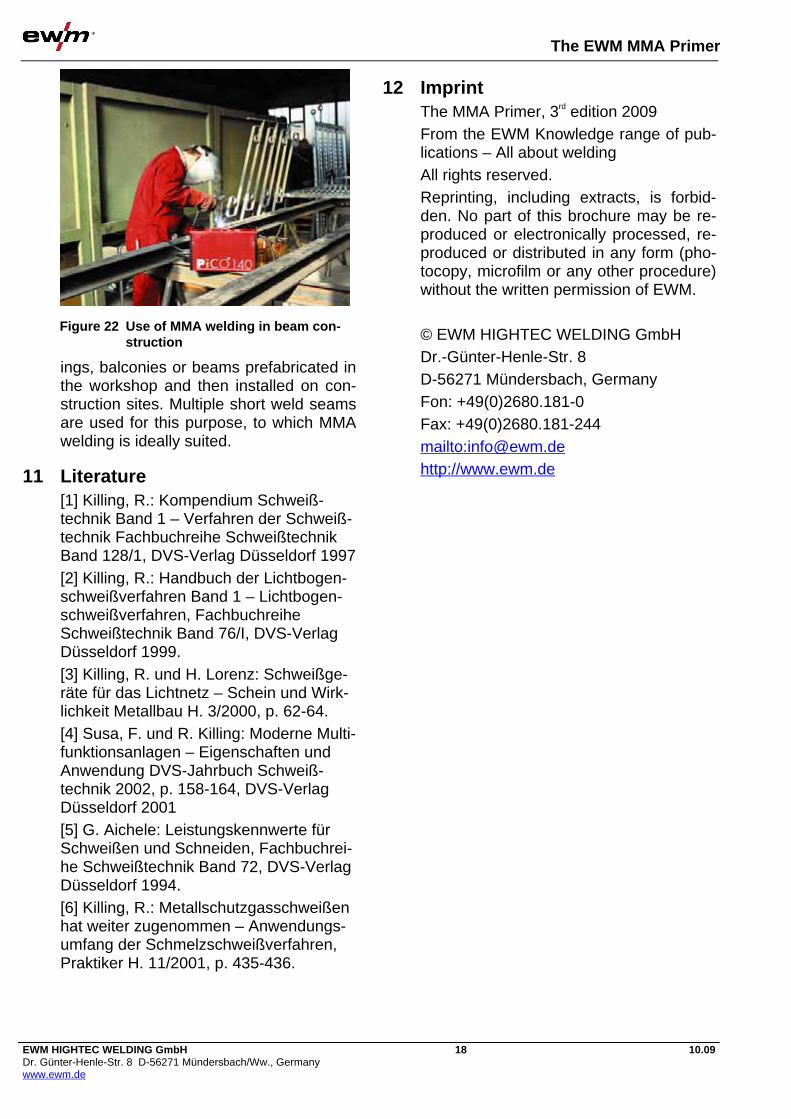
ings, balconies or beams prefabricated in the workshop and then installed on con-struction sites. Multiple short weld seams are used for this purpose, to which MMA welding is ideally suited.
11 Literature [1] Killing, R.: Kompendium Schweiß-technik Band 1 – Verfahren der Schweiß-technik Fachbuchreihe Schweißtechnik Band 128/1, DVS-Verlag Düsseldorf 1997 [2] Killing, R.: Handbuch der Lichtbogen-schweißverfahren Band 1 – Lichtbogen-schweißverfahren, Fachbuchreihe Schweißtechnik Band 76/I, DVS-Verlag Düsseldorf 1999. [3] Killing, R. und H. Lorenz: Schweißge-räte für das Lichtnetz – Schein und Wirk-lichkeit Metallbau H. 3/2000, p. 62-64. [4] Susa, F. und R. Killing: Moderne Multi-funktionsanlagen – Eigenschaften und Anwendung DVS-Jahrbuch Schweiß-technik 2002, p. 158-164, DVS-Verlag Düsseldorf 2001 [5] G. Aichele: Leistungskennwerte für Schweißen und Schneiden, Fachbuchrei-he Schweißtechnik Band 72, DVS-Verlag Düsseldorf 1994. [6] Killing, R.: Metallschutzgasschweißen hat weiter zugenommen – Anwendungs-umfang der Schmelzschweißverfahren, Praktiker H. 11/2001, p. 435-436.
12 Imprint The MMA Primer, 3rd edition 2009 From the EWM Knowledge range of pub-lications – All about welding All rights reserved. Reprinting, including extracts, is forbid-den. No part of this brochure may be re-produced or electronically processed, re-produced or distributed in any form (pho-tocopy, microfilm or any other procedure) without the written permission of EWM. © EWM HIGHTEC WELDING GmbH Dr.-Günter-Henle-Str. 8
D-56271 Mündersbach, Germany Fon: +49(0)2680.181-0 Fax: +49(0)2680.181-244 mailto:[email protected] http://www.ewm.de
Figure 22 Use of MMA welding in beam con-struction

TIG PRIMER

The EWM TIG Primer
EWM HIGHTEC WELDING GmbH Dr. Günter-Henle-Str. 8 D-56271 Mündersbach/Ww., Germany www.ewm.de
1 10.09
Contents 1 Preface.................................................................................................................................................. 2
2 The process .......................................................................................................................................... 2 2.1 General ............................................................................................................................................ 2 2.2 Current type ..................................................................................................................................... 3 2.3 Electrodes ........................................................................................................................................ 3 2.4 Shielding gases................................................................................................................................ 4
3 Groove preparation ............................................................................................................................... 5 3.1 Groove shapes................................................................................................................................. 5 3.2 Placement of the weld groove side walls side walls ........................................................................ 5 3.3 Backing ............................................................................................................................................ 5 3.4 Forming............................................................................................................................................ 5
4 The welding torch.................................................................................................................................. 6 4.1 Cooling............................................................................................................................................. 6 4.2 Torch design .................................................................................................................................... 7 4.3 Shape of the electrode tip................................................................................................................ 7
5 Welding machines................................................................................................................................. 8 5.1 Control ............................................................................................................................................. 8 5.2 Power sources ................................................................................................................................. 9
6 Performing welding work..................................................................................................................... 11 6.1 Choice of welding filler ................................................................................................................... 11 6.2 Setting the shielding gas quantity .................................................................................................. 11 6.3 Cleaning the workpiece surface..................................................................................................... 12 6.4 Igniting the arc ............................................................................................................................... 12 6.5 Moving the torch ............................................................................................................................ 13 6.6 Magnetic arc blow.......................................................................................................................... 13 6.7 Welding positions........................................................................................................................... 14 6.8 Set welding parameters ................................................................................................................. 14 6.9 Welding with current pulses........................................................................................................... 15 6.10 Automation options ........................................................................................................................ 16 6.11 Work safety .................................................................................................................................... 16
7 Special features of different materials ................................................................................................ 17 7.1 Unalloyed and non-alloy steels...................................................................................................... 18 7.2 Austenitic CrNi steels..................................................................................................................... 18 7.3 Aluminium and aluminium alloys ................................................................................................... 18 7.4 Copper and copper alloys.............................................................................................................. 20 7.5 Other materials .............................................................................................................................. 20
8 Applications for TIG welding ............................................................................................................... 21 8.1 Uses in manufacturing ................................................................................................................... 21 8.2 Example applications..................................................................................................................... 21
9 Literature ............................................................................................................................................. 22
10 Imprint ................................................................................................................................................. 23

The EWM TIG Primer
EWM HIGHTEC WELDING GmbH Dr. Günter-Henle-Str. 8 D-56271 Mündersbach/Ww., Germany www.ewm.de
2 10.09
1 Preface The TIG welding process (Figure 1) – the full name of this process irrespective to DIN 1910 – Part 4 is Tungsten Inert Gas welding – originated in the USA where in 1936 it was known as argon arc welding. It was not introduced to Germany until af-ter the Second World War. The process differs from other fusion welding tech-niques in that it offers various interesting advantages. For example, it is a general purpose technique. If a metallic material is suitable for fusion welding, it can be joined using this process. It is also a very "clean" process which generates virtually no spatter and a minimal amount of harmful substances and when used cor-rectly, guarantees a high quality welded joint. Another significant advantage of TIG welding is that unlike other processes which use melting electrodes, there is no correlation between the addition of weld-ing filler material and the current intensity. This means that the welder can match the current optimally to the welding task and only add the quantity of welding filler material actually required. This makes the process especially well suited to welding root passes and for out-of-position weld-ing. These advantages have meant that the TIG process is used successfully in many sectors of trade and industry today. However, for manual welding it does de-mand special skills on the part of the welder, and a good level of training. This
brochure explains the particular features of this process and may even generate interest in companies who are not yet us-ing the technique despite having welding tasks which would be suitable for the process.
2 The process
2.1 General TIG welding is a gas-shielded welding process with non-consumable electrode (Process No. 14). ISO 857-1 describes the process as follows: "Gas-shielded arc welding process using a non-consumable electrode made from pure or doped tungsten in which the arc and the welding molten pool is protected by a gas coating made from inert gas" With tungsten inert gas welding (process no. 141) the arc burns freely, with plasma arc welding (process no. 15), which is another gas-shielded welding process us-ing a non-consumable electrode, it is constricted. Figure 2 shows a diagram of the process.
Figure 1 TRITON 260 DC, TIG welding of cooling spirals
Torch
T-electrode
Seam
Molten bath
Arc
Welding rod
Parent material
Figure 2 Principle of TIG welding

The EWM TIG Primer
EWM HIGHTEC WELDING GmbH Dr. Günter-Henle-Str. 8 D-56271 Mündersbach/Ww., Germany www.ewm.de
3 10.09
The process is named after the type of electrode (tungsten) and the shielding gas used (inert). The electrode does not melt due to the high melting point of tungsten (3380°C) when the process is used correctly. It acts solely as the arc carrier. The welding filler is added by hand in the form of a bar or with fully automated welding as a wire via a sepa-rate feed system. The shielding gas is emitted from the shielding gas nozzle and surrounds the electrode concentrically, protecting the electrode and the weld metal underneath it from the atmosphere.
2.2 Current type Direct current is normally used for TIG welding. When welding steel and many other metals and alloys, the colder minus pole is positioned against the electrode and the hotter plus pole on the work-piece. The current-carrying capacity and the service life of the electrode are con-siderably greater with this polarity than with plus pole welding. Alternating current is used with aluminium and aluminium al-loys, and with some bronzes, in other words materials which form high-melting or highly viscous oxides. This will be cov-ered in more detail later on. When weld-ing with alternating current, the current-carrying capacity also is still lower than direct current welding on the minus pole – for more on this, please see Table 1.
There are also differences in the fusion penetration characteristics. The optimum situation is direct current welding on the minus pole. When welding with alternat-ing current, the fusion penetration is flat-ter and wider simply because of the less pointed shape of the electrode and lowest on the plus pole due to the low current-carrying capacity (Figure 3).
2.3 Electrodes Tungsten electrodes cannot be manufac-tured by moulding because of the high melting point of the metal. They are therefore manufactured using powder metallurgy techniques via sintering fol-lowed by compression and compaction. The standard diameters defined in DIN EN 26848 (ISO 6848) are between 0.5 and 10 mm. The diameters most com-monly used are 1.6; 2.0; 2.5; 3.2 and 4.0 mm. Standard lengths are 50, 75, 150 and 175 mm. The length is based around the design of the torch, among other fac-tors. As well as electrodes made from pure tungsten, there are also electrodes which have quantities of around 0.5 to 4% oxide such as thorium oxide, zircon oxide, lan-thanum oxide or cerium oxide mixed in before sintering. The use of pure tung-sten electrodes creates a very quiet arc, however electrodes containing oxide have the advantage that they heat up less during use because the coming out of the electrodes with the oxide in the electrodes occurs more readily than with the tungsten. The ease of ignition, cur-rent-carrying capacity and service life are therefore better with types containing ox-ides. Table 1 with values from DIN EN 26848 contains the recom-
D.C. [A] A.C. [A]
Minus pole on the
electrode
Plus pole on
the electrode
Ele
ctro
de d
iam
eter
[mm
]
Pur
e tu
ng-
sten
Tun
gste
n
with
oxi
de
Pur
e tu
ng-
sten
Tun
gste
n
with
oxi
de
Pur
e tu
ng-
sten
Tun
gste
n
with
oxi
de
1.6 40-130 60-150 10-20 10-20 45-90 60-125
2.0 75-180 100-200 15-25 15-25 65-125 85-160
2.5 130-230 170-250 17-30 17-30 80-140 120-210
3.2 160-310 225-330 20-35 20-35 150-190 150-250
4.0 275-450 350-480 35-50 35-50 180-260 240-350
5.0 400-625 500-675 50-70 50-70 240-350 330-460
Table 1: Recommended current intensity ranges for tungsten electrodes, val-ues acc. to DIN EN 26848
a) b) c)
Figure 3: Fusion penetration with different current types a) D.c. (minus pole) b) D.c. (plus pole) c) A.c.
The EWM TIG Primer
EWM HIGHTEC WELDING GmbH Dr. Günter-Henle-Str. 8 D-56271 Mündersbach/Ww., Germany www.ewm.de
4 10.09
mended current intensity ranges of pure tungsten electrodes and those with added oxides on both poles with direct current and alternating current, for comparison purposes. This explains the higher cur-rent carrying capacity thanks to the added oxides. Previously, tungsten electrodes with around 2% thorium oxide were generally used. The use of these is declining, how-ever. Thorium is an alpha emitter which is why electrodes containing thorium oxide also emit a low level of radioactivity. This in itself is not dangerous to the welder, al-though it does increase the general radia-tion load. What is more dangerous, however, is breathing in the dust from grinding the electrode. This is why today tungsten electrodes containing “arc-friendly” materials such as lanthanum ox-ide or cerium oxide are often used. Electrodes can be identified by the code and the identifying colour specified in the standards (Table 2).
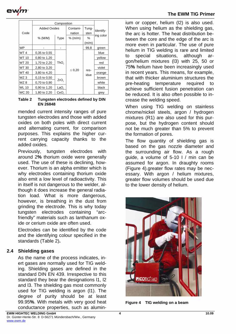
2.4 Shielding gases As the name of the process indicates, in-ert gases are normally used for TIG weld-ing. Shielding gases are defined in the standard DIN EN 439. Irrespective to this standard they bear the designations l1, l2 and l3. The shielding gas most commonly used for TIG welding is argon (l1). The degree of purity should be at least 99.95%. With metals with very good heat conductance properties, such as alumin-
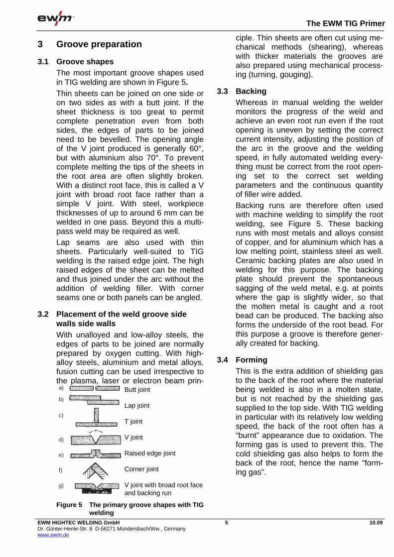
ium or copper, helium (l2) is also used. When using helium as the shielding gas, the arc is hotter. The heat distribution be-tween the core and the edge of the arc is more even in particular. The use of pure helium in TIG welding is rare and limited to special situations, although ar-gon/helium mixtures (l3) with 25, 50 or 75% helium have been increasingly used in recent years. This means, for example, that with thicker aluminium structures the pre-heating temperature required to achieve sufficient fusion penetration can be reduced. It is also often possible to in-crease the welding speed. When using TIG welding on stainless chrome/nickel steels, argon / hydrogen mixtures (R1) are also used for this pur-pose, but the hydrogen content should not be much greater than 5% to prevent the formation of pores. The flow quantity of shielding gas is based on the gas nozzle diameter and the surrounding air flow. As a rough guide, a volume of 5-10 I / min can be assumed for argon. In draughty rooms (Figure 4).greater flow rates may be nec-essary. With argon / helium mixtures, greater flow volumes should be used due to the lower density of helium.
Composition
Added Oxides Contami-
nation
Tung-
sten Code
% (M/M) Type % (m/m) %
(m/m)
Identify-
ing color
WP - - 99,8 green
WT 4 0,35 to 0,55 blue
WT 10 0,80 to 1,20 yellow
WT 20 1,70 to 2,20 red
WT 30 2,80 to 3,20 violet
WT 40 3,80 to 4,20
ThO2
orange
WZ 3 0,15 to 0,50 brown
WZ 8 0,70 to 0,90 ZrO2 white
WL 10 0,90 to 1,20 LaO2 black
WC 20 1,80 to 2,20 CeO2
0,20 res-
idue
grey
Table 2 Tungsten electrodes defined by DIN EN 26848
Figure 4 TIG welding on a beam
The EWM TIG Primer
EWM HIGHTEC WELDING GmbH Dr. Günter-Henle-Str. 8 D-56271 Mündersbach/Ww., Germany www.ewm.de
5 10.09
3 Groove preparation
3.1 Groove shapes The most important groove shapes used in TIG welding are shown in Figure 5. Thin sheets can be joined on one side or on two sides as with a butt joint. If the sheet thickness is too great to permit complete penetration even from both sides, the edges of parts to be joined need to be bevelled. The opening angle of the V joint produced is generally 60°, but with aluminium also 70°. To prevent complete melting the tips of the sheets in the root area are often slightly broken. With a distinct root face, this is called a V joint with broad root face rather than a simple V joint. With steel, workpiece thicknesses of up to around 6 mm can be welded in one pass. Beyond this a multi-pass weld may be required as well. Lap seams are also used with thin sheets. Particularly well-suited to TIG welding is the raised edge joint. The high raised edges of the sheet can be melted and thus joined under the arc without the addition of welding filler. With corner seams one or both panels can be angled.
3.2 Placement of the weld groove side walls side walls With unalloyed and low-alloy steels, the edges of parts to be joined are normally prepared by oxygen cutting. With high-alloy steels, aluminium and metal alloys, fusion cutting can be used irrespective to the plasma, laser or electron beam prin-
ciple. Thin sheets are often cut using me-chanical methods (shearing), whereas with thicker materials the grooves are also prepared using mechanical process-ing (turning, gouging).
3.3 Backing Whereas in manual welding the welder monitors the progress of the weld and achieve an even root run even if the root opening is uneven by setting the correct current intensity, adjusting the position of the arc in the groove and the welding speed, in fully automated welding every-thing must be correct from the root open-ing set to the correct set welding parameters and the continuous quantity of filler wire added. Backing runs are therefore often used with machine welding to simplify the root welding, see Figure 5. These backing runs with most metals and alloys consist of copper, and for aluminium which has a low melting point, stainless steel as well. Ceramic backing plates are also used in welding for this purpose. The backing plate should prevent the spontaneous sagging of the weld metal, e.g. at points where the gap is slightly wider, so that the molten metal is caught and a root bead can be produced. The backing also forms the underside of the root bead. For this purpose a groove is therefore gener-ally created for backing.
3.4 Forming This is the extra addition of shielding gas to the back of the root where the material being welded is also in a molten state, but is not reached by the shielding gas supplied to the top side. With TIG welding in particular with its relatively low welding speed, the back of the root often has a “burnt” appearance due to oxidation. The forming gas is used to prevent this. The cold shielding gas also helps to form the back of the root, hence the name “form-ing gas”.
a)
b)
c)
d)
e)
f)
g)
Butt joint Lap joint T joint V joint Raised edge joint Corner joint V joint with broad root face and backing run
Figure 5 The primary groove shapes with TIG welding

The EWM TIG Primer
EWM HIGHTEC WELDING GmbH Dr. Günter-Henle-Str. 8 D-56271 Mündersbach/Ww., Germany www.ewm.de
6 10.09
Thanks to the forming process, the for-mation of oxide skins and annealing col-ours on the back of the root is also prevented, or at least reduced. This is important when welding corrosion-resistant steels, for example, because these oxide skins impair the corrosion-resistance of the weld (Figure 6). When welding pipes, the ends can simply be blocked and the forming gas fed into
the interior. When welding metal panels, it can be allowed to flow out of openings in the backing bars. Argon or an argon / hydrogen mixture can be used as the forming gas. In DIN EN 439 reasonably priced forming gases are also defined in group F. These consist of a hydro-gen/nitrogen mixture, for example. Pure nitrogen can also be used for forming un-der certain circumstances.
4 The welding torch The welding torch is the TIG welder’s tool. Its function has a significant impact on the weld seam produced. Figure 7 shows a gas cooled TIG welding torch. The torch is connected to the welding machine via the tube package. The weld-ing current lead runs through the tube package, along with the shielding gas supply and the control lead which allows various functions to be switched on and off using the switch on the torch.
4.1 Cooling With torches designed for current intensi-ties up to around 150 amperes only, the cooling from the shielding gas flowing through and the surrounding air is suffi-cient. Higher power torches are water cooled. In this case, the leads for the wa-ter supply and water return also run through the hose package, whereby the welding current lead is cooled by the re-turned water. It need not therefore be very large and the hose package remains flexible. For this purpose there is a com-bined current/water cable in the hose package. A pressure monitor, generally installed in the welding machine, ensures that if the cooling water supply is too low or missing, the welding current is switched off. As water is a relatively expensive operat-ing material, return water equipment is normally used for cooling with a closed coolant circuit.
Figure 6 TIG welding work in the chemical industry
MISTRAL
Figure 7 Gas cooled TIG welding torch

The EWM TIG Primer
EWM HIGHTEC WELDING GmbH Dr. Günter-Henle-Str. 8 D-56271 Mündersbach/Ww., Germany www.ewm.de
7 10.09
4.2 Torch design The tungsten electrode is positioned in a collet and is secured by tightening the torch cap. The length of the torch cap is selected irrespective to the application. For example, when welding in tight spaces it may be significantly shorter than shown in Figure 8. The torch switch has an important func-tion. It may be designed in the form of one or two key buttons or as a rocker switch which is operated by moving it backwards and forwards. The welding current can be switched on and off by pressing the key button, but the current can also be adjusted during welding. The speed of the change in current can also be set using this button. The diameter of the tungsten electrode is based on the current intensity being used, the current type (direct/alternating current) and the polarity. You may find the current intensity ranges given in Ta-ble 1 useful when selecting the diameter. At the bottom end of the welding torch is the gas nozzle. This may consist of metal or ceramic material. The diameter of the gas nozzle must be matched to the weld-ing task. If a larger molten bath is being protected, the gas nozzle also needs to be larger. One ration used is therefore to the current intensity or to the electrode diameter. The tungsten electrode extends beyond the gas nozzle depending on the diameter, e.g. 2mm with thin electrodes or up to 3mm with thicker electrodes.
4.3 Shape of the electrode tip In direct current welding (minus pole) the tungsten electrode normally has a cone
shape. This is generally achieved by grinding. The grinding should be carried out so that grinding grooves remain in the longitudinal direction on the ground tip only. This means that the arc starts more quietly than if there were crosswise grooves. The starting angle is given by the ratio between the electrode diameter and the length of the tip. This ratio should be around 1: 2.5. With the current intensity set correctly, only a small part of the electrode tip melts and forms a small ball there. The arc burns particularly quietly on this. It is therefore advisable to create this ball be-fore starting welding via short-term over-load. With modern equipment, this type of function can be initiated from the control. In alternating current welding the thermal loading of the tungsten electrode is sig-nificantly greater than with direct current welding (minus pole). The electrode is therefore either not tipped at all with this current type, or is shaped into a truncated cone with a ratio between both diameters of 2:1. In direct current welding (plus pole), which is relatively rare, the electrode is not ground at all. It should be noted that the shape of the electrode tip also has a significant impact on the fusion penetration characteristics. With a pointed electrode, narrower, deeper fusion penetration is produced, and with a more truncated electrode, the fusion penetration is wider and flatter in otherwise the same conditions (Figure 9).
Gas nozzle
Collet casing
Teflon sealCollet Torch cap
Figure 8 Exploded diagram of the TIG weld-ing torch
Figure 9 Fusion penetration with different electrode tip shapes

The EWM TIG Primer
EWM HIGHTEC WELDING GmbH Dr. Günter-Henle-Str. 8 D-56271 Mündersbach/Ww., Germany www.ewm.de
8 10.09
5 Welding machines TIG welding machines consist of the cur-rent source and the control.
5.1 Control The control has the task of switching the welding current on and off, adjusting it and keeping it constant. It also provides additional functions which actually allow welding to be carried out or which simplify the process (Figure 10). With modern machines the current can be reduced in a time-controlled way for crater filling (down-slope) when switching off at the end of a weld seam. The current can also be raised gradually at the start of welding (up-slope). These functions can be initiated from the torch switch in non-latched and latched operation. This produces a welding program as shown in Figure 11. With high-tech machines the set rise and lower times remain constant, regardless of the current intensity level set. The pre- and post-flow times for the shielding gas can also be set. Also integrated into the control is the igni-tion unit. Naturally the TIG arc can also be ignited by touching between the elec-trode and the workpiece, but in this case there is a risk of the electrode tip becom-ing damaged and the arc burning erratic-ally. It is also possible that tungsten is transferred into the weld metal where it would not melt due to the high melting point but would remain as a foreign body. For this reason, with simple machines
which do not have specific devices for non-contact ignition, the arc should al-ways be ignited outside the groove on a run-on plate or on an adjacent copper panel. There are various ways of igniting the arc without damaging the electrode. With high voltage pulse ignition, sometimes also called high frequency ignition, a pulsed alternating current of several thousand voIts (e.g. 6-8 kV) is created between the electrode and the workpiece. The very short voltage pulses (e.g. 0.5-1s) are transferred from the electrode to the workpiece in the form of a spark gap after the torch switch is pressed; with di-rect current welding generally at a fre-quency of 100 Hz, and with alternating current at the standard 50 Hz frequency or with modern machines at the fre-quency set for the welding current. The spark gap can be heard and seen. It pre-ionises the gas molecules in the space between the electrode and the workpiece so that the arc ignites without contact when the electrode tip is moved to a few millimetres away from the arc strike. One rule of thumb is that ignition is possible across a gap of 1 mm / 1000 volt ignition voltage. To prevent accidental contact between the electrode and the workpiece, it is best to angle the position of the torch on the edge of the gas nozzle, as shown in Figure 12, and to move the electrode tip closer by straightening up the torch, until the arc ignites. Only then is the gas nozzle raised off the workpiece and the normal torch position adopted. When welding using sinusoidal alternating current the igniting aid must
Figure 10 Control for the EWM TIG Inverter current source TRITON 220 DC powerSinus
I
Istart
AMP
tUp tDown
Iend
t
Figure 11 Function sequence at the start and end of welding

The EWM TIG Primer
EWM HIGHTEC WELDING GmbH Dr. Günter-Henle-Str. 8 D-56271 Mündersbach/Ww., Germany www.ewm.de
9 10.09
actually burn through to reignite the arc safely after the current and voltage pass through zero. Another option is what is known as "lift-arc" ignition. This is a contact ignition type in which the electrode is not dam-aged because during the contact only a very small current is flowing. Only once a weak arc is burning when the electrode is lifted off is the set welding current con-nected by the control. Further functions of the control include switching from normal operation to pulse operation and, where applicable, also switching to other welding processes, whereby in some circumstances the characteristics may need to be changed.
5.2 Power sources The current source has the task of con-verting the high voltage/low current alter-nating current coming from the mains into high current/low voltage welding current and where applicable, to rectify the weld-ing current as well. For TIG welding both alternating current and direct current are used. The welding transformer is the most sim-ple and most cost-effective welding cur-rent source. It consists of the primary coil with numerous thin windings and the secondary coil with a few thick windings. The mains current is transformed up-wards in relation to the number of wind-ings on this coil, and the mains voltage is transformed downwards irrespectively. The welding transformer normally has a falling static characteristic. Different cur-rent intensities can be set via scattering kernel adjustment, transducer or primary side turn tapping.
The welding rectifier consists of a trans-former with a downstream rectifier stack (Figure 13). Today silicon diodes or thyristors are used as rectifiers. In these devices the al-ternating current previously transformed in the transformer to the required current intensity and voltage is converted into di-rect current. Single welding rectifiers are single-phase connected (double-pulse bridge). They produce a welding current with considerable ripples. Improved smoothing of the current is achieved when all 3 phases of the alternating cur-rent are transformed and rectified (six-pulse bridge connection). Single rectifiers are also available as combined devices which can be switched to supply either di-rect or alternating current. Welding recti-fiers for TIG welding have a falling static characteristic. They can be set using scattering kernel adjustment, transducer and primary side turn tapping in the a.c. circuit or via phase shift control of the thy-ristors. Modern TIG systems (Figure 14) are equipped with inverters as the power
Figure 12 Ignition with high voltage pulses
Figure 13 Basic diagram of the welding recti-fier
Figure 14 TRITON 220 DC, TIG Inverter weld-ing machine
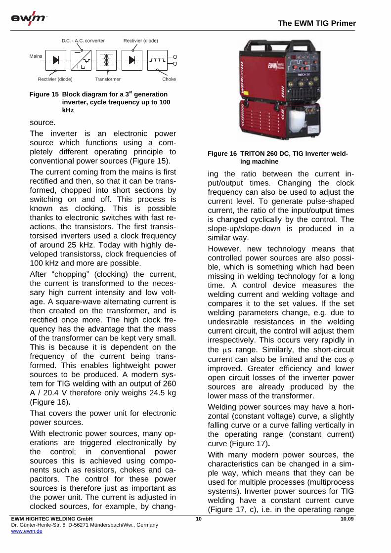
The EWM TIG Primer
EWM HIGHTEC WELDING GmbH Dr. Günter-Henle-Str. 8 D-56271 Mündersbach/Ww., Germany www.ewm.de
10 10.09
source. The inverter is an electronic power source which functions using a com-pletely different operating principle to conventional power sources (Figure 15). The current coming from the mains is first rectified and then, so that it can be trans-formed, chopped into short sections by switching on and off. This process is known as clocking. This is possible thanks to electronic switches with fast re-actions, the transistors. The first transis-torsised inverters used a clock frequency of around 25 kHz. Today with highly de-veloped transistorss, clock frequencies of 100 kHz and more are possible. After “chopping” (clocking) the current, the current is transformed to the neces-sary high current intensity and low volt-age. A square-wave alternating current is then created on the transformer, and is rectified once more. The high clock fre-quency has the advantage that the mass of the transformer can be kept very small. This is because it is dependent on the frequency of the current being trans-formed. This enables lightweight power sources to be produced. A modern sys-tem for TIG welding with an output of 260 A / 20.4 V therefore only weighs 24.5 kg (Figure 16). That covers the power unit for electronic power sources. With electronic power sources, many op-erations are triggered electronically by the control; in conventional power sources this is achieved using compo-nents such as resistors, chokes and ca-pacitors. The control for these power sources is therefore just as important as the power unit. The current is adjusted in clocked sources, for example, by chang-
ing the ratio between the current in-put/output times. Changing the clock frequency can also be used to adjust the current level. To generate pulse-shaped current, the ratio of the input/output times is changed cyclically by the control. The slope-up/slope-down is produced in a similar way. However, new technology means that controlled power sources are also possi-ble, which is something which had been missing in welding technology for a long time. A control device measures the welding current and welding voltage and compares it to the set values. If the set welding parameters change, e.g. due to undesirable resistances in the welding current circuit, the control will adjust them irrespectively. This occurs very rapidly in the s range. Similarly, the short-circuit current can also be limited and the cos improved. Greater efficiency and lower open circuit losses of the inverter power sources are already produced by the lower mass of the transformer. Welding power sources may have a hori-zontal (constant voltage) curve, a slightly falling curve or a curve falling vertically in the operating range (constant current) curve (Figure 17). With many modern power sources, the characteristics can be changed in a sim-ple way, which means that they can be used for multiple processes (multiprocess systems). Inverter power sources for TIG welding have a constant current curve (Figure 17, c), i.e. in the operating range
D.C. - A.C. converter Rectivier (diode)
Rectivier (diode)
Mains
Transformer Choke
Figure 15 Block diagram for a 3rd generation inverter, cycle frequency up to 100 kHz
Figure 16 TRITON 260 DC, TIG Inverter weld-ing machine
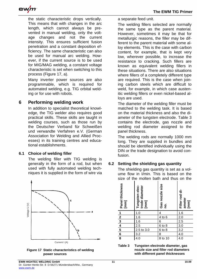
The EWM TIG Primer
EWM HIGHTEC WELDING GmbH Dr. Günter-Henle-Str. 8 D-56271 Mündersbach/Ww., Germany www.ewm.de
11 10.09
the static characteristic drops vertically. This means that with changes in the arc length, which cannot always be pre-vented in manual welding, only the volt-age changes and not the current intensity. This ensures sufficient fusion penetration and a constant deposition ef-ficiency. The same characteristic can also be used for manual arc welding. How-ever, if the current source is to be used for MIG/MAG welding, a constant voltage characteristic is set when switching to this process (Figure 17, a). Many inverter power sources are also programmable, which is required for automated welding, e.g. TIG orbital weld-ing or for use with robots.
6 Performing welding work In addition to specialist theoretical knowl-edge, the TIG welder also requires good practical skills. These skills are taught in welding courses, such as those run by the Deutscher Verband für Schweißen und verwandte Verfahren e.V. (German Association for Welding and Allied Proc-esses) in its training centres and educa-tional establishments.
6.1 Choice of welding filler The welding filler with TIG welding is generally in the form of a rod, but when used with fully automated welding tech-niques it is supplied in the form of wire via
a separate feed unit. The welding fillers selected are normally the same type as the parent material. However, sometimes it may be that for metallurgic reasons, the filler may be dif-ferent to the parent material with some al-loy elements. This is the case with carbon content, for example, that is kept very low, wherever possible, to increase the resistance to cracking. Such fillers are known as equivalent welding fillers in these situations. There are also situations where fillers of a completely different type are required. This is the case when join-ing carbon steels which are difficult to weld, for example, in which case austen-itic welding fillers or even nickel-based al-loys are used. The diameter of the welding filler must be matched to the welding task. It is based on the material thickness and also the di-ameter of the tungsten electrode. Table 3 contains the electrode, gas nozzle and welding rod diameter assigned to the panel thickness. The welding rods are normally 1000 mm long. They are supplied in bundles and should be identified individually using the DIN or the trade designation to avoid con-fusion.
6.2 Setting the shielding gas quantity The shielding gas quantity is set as a vol-ume flow in I/min. This is based on the size of the molten bath and thus on the
Table 3 Tungsten electrode diameter, gas nozzle size and filler rod diameters with different panel thicknesses
Current I (A)
Vol
tage
U (
V)
Figure 17 Static characteristics of welding power sources
Pan
el t
hic
knes
s [m
m]
Tu
ng
sten
ele
c-tr
od
e d
iam
eter
[m
m]
Gas
no
zzle
siz
e n
o.
Fill
er r
od
di-
amet
er
[mm
]
1 1.0 4 1.6 2 1.6 4 to 6 2.0 3 1.6 6 2.5 4 2.5 6 to 8 3.0 5 2.5 to 3.0 6 to 8 3.2 6 3.2 8 4.0 8 4.0 8 to 10 4.0
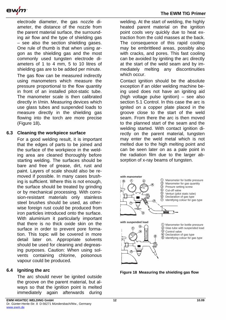
The EWM TIG Primer
EWM HIGHTEC WELDING GmbH Dr. Günter-Henle-Str. 8 D-56271 Mündersbach/Ww., Germany www.ewm.de
12 10.09
electrode diameter, the gas nozzle di-ameter, the distance of the nozzle from the parent material surface, the surround-ing air flow and the type of shielding gas – see also the section shielding gases. One rule of thumb is that when using ar-gon as the shielding gas and the most commonly used tungsten electrode di-ameters of 1 to 4 mm, 5 to 10 litres of shielding gas are to be added per minute. The gas flow can be measured indirectly using manometers which measure the pressure proportional to the flow quantity in front of an installed pitot-static tube. The manometer scale is then calibrated directly in I/min. Measuring devices which use glass tubes and suspended loads to measure directly in the shielding gas flowing into the torch are more precise (Figure 18).
6.3 Cleaning the workpiece surface For a good welding result, it is important that the edges of parts to be joined and the surface of the workpiece in the weld-ing area are cleaned thoroughly before starting welding. The surfaces should be bare and free of grease, dirt, rust and paint. Layers of scale should also be re-moved if possible. In many cases brush-ing is sufficient. Where this is not enough, the surface should be treated by grinding or by mechanical processing. With corro-sion-resistant materials only stainless steel brushes should be used, as other-wise foreign rust could be produced from iron particles introduced onto the surface. With aluminium it particularly important that there is no thick oxide skin on the surface in order to prevent pore forma-tion. This topic will be covered in more detail later on. Appropriate solvents should be used for cleaning and degreas-ing purposes. Caution: When using sol-vents containing chlorine, poisonous vapour could be produced.
6.4 Igniting the arc The arc should never be ignited outside the groove on the parent material, but al-ways so that the ignition point is melted immediately again afterwards during
welding. At the start of welding, the highly heated parent material on the ignition point cools very quickly due to heat ex-traction from the cold masses at the back. The consequence of this rapid cooling may be embrittleed areas, possibly also with cracks, and pores. This fast cooling can be avoided by igniting the arc directly at the start of the weld seam and by im-mediately melting any discontinuities which occur. Contact ignition should be the absolute exception if an older welding machine be-ing used does not have an igniting aid (high voltage pulse ignition) – see also section 5.1 Control. In this case the arc is ignited on a copper plate placed in the groove close to the start of the weld seam. From there the arc is then moved to the planned start of the seam and the welding started. With contact ignition di-rectly on the parent material, tungsten may enter the weld metal which is not melted due to the high melting point and can be seen later on as a pale point in the radiation film due to the larger ab-sorption of x-ray beams of tungsten.
Manometer for bottle pressure
Manometer for bottle pressure
Manometer for gas quantityPresure setting screwCut-off valveVenturi (pilot static tube)Declaration of gas type
Declaration of gas type
Glas tube with suspended loadControl valve
Identifying colour for gas type
Identifying colour for gas type
with manometer
with suspended load
Figure 18 Measuring the shielding gas flow
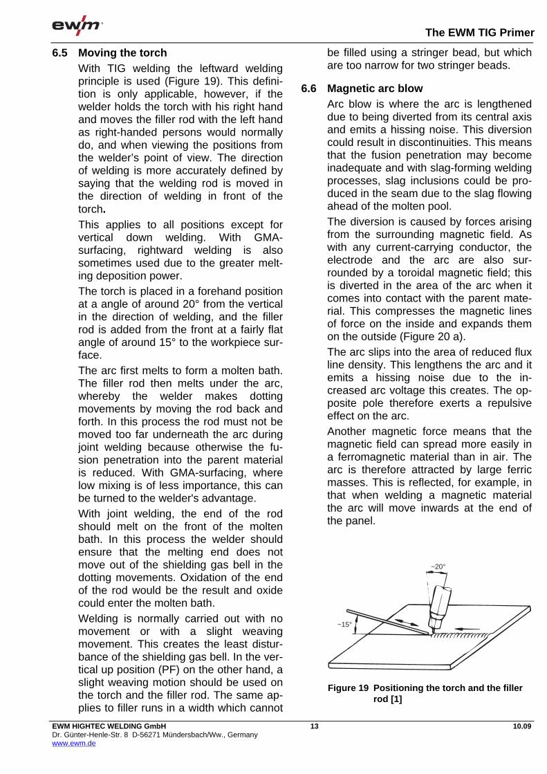
The EWM TIG Primer
EWM HIGHTEC WELDING GmbH Dr. Günter-Henle-Str. 8 D-56271 Mündersbach/Ww., Germany www.ewm.de
13 10.09
6.5 Moving the torch With TIG welding the leftward welding principle is used (Figure 19). This defini-tion is only applicable, however, if the welder holds the torch with his right hand and moves the filler rod with the left hand as right-handed persons would normally do, and when viewing the positions from the welder’s point of view. The direction of welding is more accurately defined by saying that the welding rod is moved in the direction of welding in front of the torch. This applies to all positions except for vertical down welding. With GMA-surfacing, rightward welding is also sometimes used due to the greater melt-ing deposition power. The torch is placed in a forehand position at a angle of around 20° from the vertical in the direction of welding, and the filler rod is added from the front at a fairly flat angle of around 15° to the workpiece sur-face. The arc first melts to form a molten bath. The filler rod then melts under the arc, whereby the welder makes dotting movements by moving the rod back and forth. In this process the rod must not be moved too far underneath the arc during joint welding because otherwise the fu-sion penetration into the parent material is reduced. With GMA-surfacing, where low mixing is of less importance, this can be turned to the welder's advantage. With joint welding, the end of the rod should melt on the front of the molten bath. In this process the welder should ensure that the melting end does not move out of the shielding gas bell in the dotting movements. Oxidation of the end of the rod would be the result and oxide could enter the molten bath. Welding is normally carried out with no movement or with a slight weaving movement. This creates the least distur-bance of the shielding gas bell. In the ver-tical up position (PF) on the other hand, a slight weaving motion should be used on the torch and the filler rod. The same ap-plies to filler runs in a width which cannot
be filled using a stringer bead, but which are too narrow for two stringer beads.
6.6 Magnetic arc blow Arc blow is where the arc is lengthened due to being diverted from its central axis and emits a hissing noise. This diversion could result in discontinuities. This means that the fusion penetration may become inadequate and with slag-forming welding processes, slag inclusions could be pro-duced in the seam due to the slag flowing ahead of the molten pool. The diversion is caused by forces arising from the surrounding magnetic field. As with any current-carrying conductor, the electrode and the arc are also sur-rounded by a toroidal magnetic field; this is diverted in the area of the arc when it comes into contact with the parent mate-rial. This compresses the magnetic lines of force on the inside and expands them on the outside (Figure 20 a). The arc slips into the area of reduced flux line density. This lengthens the arc and it emits a hissing noise due to the in-creased arc voltage this creates. The op-posite pole therefore exerts a repulsive effect on the arc. Another magnetic force means that the magnetic field can spread more easily in a ferromagnetic material than in air. The arc is therefore attracted by large ferric masses. This is reflected, for example, in that when welding a magnetic material the arc will move inwards at the end of the panel.
~20°
~15°
Figure 19 Positioning the torch and the filler rod [1]
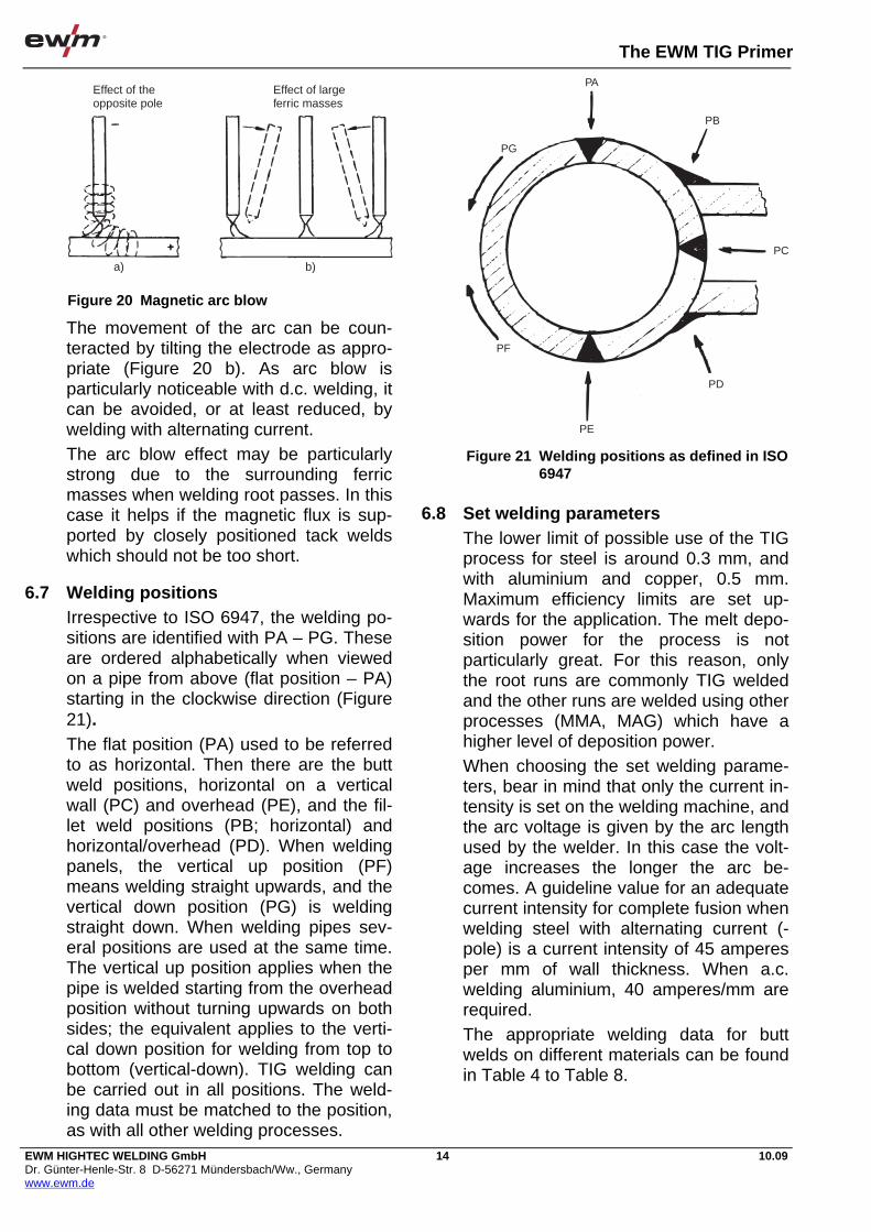
The EWM TIG Primer
EWM HIGHTEC WELDING GmbH Dr. Günter-Henle-Str. 8 D-56271 Mündersbach/Ww., Germany www.ewm.de
14 10.09
The movement of the arc can be coun-teracted by tilting the electrode as appro-priate (Figure 20 b). As arc blow is particularly noticeable with d.c. welding, it can be avoided, or at least reduced, by welding with alternating current. The arc blow effect may be particularly strong due to the surrounding ferric masses when welding root passes. In this case it helps if the magnetic flux is sup-ported by closely positioned tack welds which should not be too short.
6.7 Welding positions Irrespective to ISO 6947, the welding po-sitions are identified with PA – PG. These are ordered alphabetically when viewed on a pipe from above (flat position – PA) starting in the clockwise direction (Figure 21). The flat position (PA) used to be referred to as horizontal. Then there are the butt weld positions, horizontal on a vertical wall (PC) and overhead (PE), and the fil-let weld positions (PB; horizontal) and horizontal/overhead (PD). When welding panels, the vertical up position (PF) means welding straight upwards, and the vertical down position (PG) is welding straight down. When welding pipes sev-eral positions are used at the same time. The vertical up position applies when the pipe is welded starting from the overhead position without turning upwards on both sides; the equivalent applies to the verti-cal down position for welding from top to bottom (vertical-down). TIG welding can be carried out in all positions. The weld-ing data must be matched to the position, as with all other welding processes.
6.8 Set welding parameters The lower limit of possible use of the TIG process for steel is around 0.3 mm, and with aluminium and copper, 0.5 mm. Maximum efficiency limits are set up-wards for the application. The melt depo-sition power for the process is not particularly great. For this reason, only the root runs are commonly TIG welded and the other runs are welded using other processes (MMA, MAG) which have a higher level of deposition power. When choosing the set welding parame-ters, bear in mind that only the current in-tensity is set on the welding machine, and the arc voltage is given by the arc length used by the welder. In this case the volt-age increases the longer the arc be-comes. A guideline value for an adequate current intensity for complete fusion when welding steel with alternating current (- pole) is a current intensity of 45 amperes per mm of wall thickness. When a.c. welding aluminium, 40 amperes/mm are required. The appropriate welding data for butt welds on different materials can be found in Table 4 to Table 8.
Effect of theopposite pole
a) b)
Effect of largeferric masses
Figure 20 Magnetic arc blow
PA
PB
PG
PF
PE
PD
PC
Figure 21 Welding positions as defined in ISO 6947
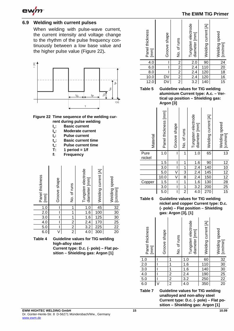
The EWM TIG Primer
EWM HIGHTEC WELDING GmbH Dr. Günter-Henle-Str. 8 D-56271 Mündersbach/Ww., Germany www.ewm.de
15 10.09
6.9 Welding with current pulses When welding with pulse-wave current, the current intensity and voltage change to the rhythm of the pulse frequency con-tinuously between a low base value and the higher pulse value (Figure 22).
Pan
el th
ickn
ess
[mm
]
Gro
ove
shap
e
No.
of r
uns
Tun
gste
n el
ectr
ode
diam
eter
[mm
]
Wel
ding
cur
rent
[A]
Wel
ding
spe
ed
[cm
/min
]
1.0 I 1 1.0 45 322.0 I 1 1.6 100 303.0 I 1 1.6 125 304.0 I 2 2.4 170 255.0 I 2 3.2 225 226.0 V 2 4.0 300 20
Table 4 Guideline values for TIG welding high-alloy steel Current type: D.c. (- pole) – Flat po-sition – Shielding gas: Argon [1]
Pan
el th
ickn
ess
[mm
]
Gro
ove
shap
e
No.
of r
uns
Tun
gste
n el
ectr
ode
diam
eter
[mm
]
Wel
ding
cur
rent
[A]
Wel
ding
spe
ed
[cm
/min
]
4.0 I 2 2.0 90 246.0 I 2 2.4 110 208.0 I 2 2.4 120 18
10.0 DV 2 2.4 120 1612.0 DV 2 3.2 140 15
Table 5 Guideline values for TIG welding aluminium Current type: A.c. – Ver-tical up position – Shielding gas: Argon [3]
Mat
eria
l
Pan
el th
ickn
ess
[mm
]
Gro
ove
shap
e
No.
of r
uns
Tun
gste
n el
ectr
ode
diam
eter
[mm
]
Wel
ding
cur
rent
[A]
Wel
ding
spe
ed
[cm
/min
]
Pure nickel
1.0 I 1 1.0 65 13
1.5 I 1 1.6 90 12 3.0 I 1 2.4 140 10 5.0 V 3 2.4 145 12 10.0 V 8 2.4 150 12Copper 1.5 I 1 1.6 130 28 3.0 I 1 3.2 200 25 5.0 I 2 4.0 270 15
Table 6 Guideline values for TIG welding nickel and copper Current type: D.c. (- pole) – Flat position – Shielding gas: Argon [3], [1]
Pan
el th
ickn
ess
[mm
]
Gro
ove
shap
e
No.
of r
uns
Tun
gste
n el
ectr
ode
diam
eter
[mm
]
Wel
ding
cur
rent
[A]
Wel
ding
spe
ed
[cm
/min
]
1.0 I 1 1.0 60 322.0 I 1 1.6 110 303.0 I 1 1.6 140 304.0 I 2 2.4 190 255.0 I 2 3.2 250 226.0 V 2 4.0 350 20
Table 7 Guideline values for TIG welding unalloyed and non-alloy steel Current type: D.c. (- pole) – Flat po-sition – Shielding gas: Argon [1]
I[A
]
t [s]
T
tG tP I G
I m
I P
Figure 22 Time sequence of the welding cur-rent during pulse welding IG: Basic current IM: Moderate current IP: Pulse current tG: Basic current time tP: Pulse current time T: 1 period = 1/f f: Frequency

The EWM TIG Primer
EWM HIGHTEC WELDING GmbH Dr. Günter-Henle-Str. 8 D-56271 Mündersbach/Ww., Germany www.ewm.de
16 10.09
Pan
el th
ickn
ess
[mm
]
Gro
ove
shap
e
No.
of r
uns
Tun
gste
n el
ectr
ode
diam
eter
[mm
]
Wel
ding
cur
rent
[A]
Wel
ding
spe
ed
[cm
/min
]
1.0 I 1 1.6 75 262.0 I 1 2.0 90 213.0 I 1 2.4 125 174.0 I 1 3.2 160 155.0 V 2 3.2 165 14 to 176.0 V 2 4.0 185 10 to 15
Table 8 Guideline values for TIG welding aluminium, current type: A.c. – flat position – shielding gas: Argon [3]
Modern inverter power sources generally allow pulse frequencies of between 0.5 and 300 Hz to be set. Special power sources also pulse in the kHz range. Whereas in the higher frequency ranges, effects such as grain refining in the weld metal and arc constriction can be pro-duced, the lower frequency range is used primarily in the flat position for better con-trol of the molten bath in out-of-position welding. This occurs as follows (Figure 23): The fusion penetration in the parent metal is produced thanks to the high pulse cur-rent and a dot-shaped molten bath is formed. This starts to become brittle from the edge inwards due to the effect of the low base current which follows, until the next current pulse melts it again and en-larges it. In the meantime the arc has al-ready been moved at the welding speed, which means that in TIG pulse welding the weld seam is created from numerous overlapping welding spots. The size of the molten bath is on average smaller than when welding with an even current,
which means that it is more easily con-trolled in out-of-position welding. Ade-quate fusion penetration is still ensured, however. The effect just described only occurs if there is a sufficient temperature difference in the molten bath between the base phase and the pulse phase. This is only the case with pulse frequencies less than around 5 Hz. One disadvantage is that the welding speed needs to be greatly reduced with pulse welding. The welder can also de-tect the pulses in the low frequency range as a disruptive flickering of the arc. This is why this type of TIG welding is used less often with manual welding where the welder has other options to control the bath than with automated TIG welding.
6.10 Automation options The manual TIG process (Figure 24) can be mechanised using simple equipment. This is of particular interest if longer lengthways seams are being welded on panels or if frequent circumferential welds are being performed on pipe-shaped bodies. When welding longitudinal seams, the torch can be fixed onto a simple travel carriage which is used to move over the weld groove side walls. If discontinuities occur in the groove geometry, it is advis-able to use backing. When welding circumferential welds, the torch is suspended stationary and the workpiece moves in a manipulator rotat-ing device underneath the torch. With complex parts welding robots are also used for TIG welding. In all cases where filler is required, this is automatically feeded to the arc in wire form.
6.11 Work safety TIG welding is a very clean process. Vir-tually no harmful gas or smoke is pro-duced, which means that no suction directly at the place of origin is required by the current work safety regulations. Fresh air is sufficient, or mechanised ven-tilation of the room. However, the welder
S = Length of melting pointL
Welding-direction
SL
UL AL
ALÜ = Length of lapL
A = Nugget spacingL
Figure 23 Structure of the weld seam from in-dividual spots [2}

The EWM TIG Primer
EWM HIGHTEC WELDING GmbH Dr. Günter-Henle-Str. 8 D-56271 Mündersbach/Ww., Germany www.ewm.de
17 10.09
must protect himself against radiation from the arc and against electrical dan-gers. To protect against the infrared and ultra-violet radiation, the TIG welder normally wears a helmet (Figure 24), which leaves both hands free for moving the torch and for adding filler metal. The filter glass is integrated into this safety helmet. This fil-ter has recently been defined in DIN EN 169. There are various grades of protec-tion which need to be permanently affixed to the glass. With TIG welding, filters of protection grades 9 to 14 are used, de-pending on the used current intensity, where grade 9 is prescribed for lower cur-rents and 14 for the higher current inten-sities. The greatest electrical risk is represented by the open circuit voltage. This is the maximum voltage which is present on the activated power source between the con-nection sockets when the arc is not burn-ing. After the arc is ignited, the voltage is much lower; in TIG welding only around 12 to 20 volts. Irrespective to the relevant German accident prevention regulations, power sources for direct current in normal operation should have an open circuit voltage peak value of max. 113 volts. With alternating current system this value is also 113 volts, but the r.m.s. value is limited to max. 80 volts. Where there is
an increased risk of electric shock, e.g. when welding in small spaces or on large iron masses, reduced values apply for al-ternating current, e.g. a peak value of 68 volts and an r.m.s. value of 48 volts. Modern welding power sources meeting these requirements bear the “S” safety sign in conformance with DIN EN 60974-1. Older power sources may still be marked with “K” (d.c.) or “42 V” (a.c.). The safest way for welders to protect themselves against electric shocks is to wear undamaged welding gloves made from leather and well-insulated work clothes including safety shoes.
7 Special features of different ma-terials As already mentioned, the TIG process is suitable for welding a large range of ma-terials. Some materials are welded using direct current, and others using alternat-ing current. Table 9 lists which materials are better welded with direct current, and which with alternating current. The sections below cover various special features of the different materials.
D. c. Material
Ele
ctro
de
“–“
pole
Ele
ctro
de
“+”
pole
A.c
.
Carbon steel XX - -
Stainless steel XX - -
Aluminium and Al alloys - X 1) XX
Magnesium and Mg alloys - X 1) XX
Copper XX - -
Aluminium bronze X - XX
Silicon bronze XX - -
Brass X - XX
Nickel and Ni alloys XX - X
Titanium XX - -
Table 9 Suitable current type for different materials, shielding gas: Pure argon 1) for thin materials only XX = best results, X = can be used, - = not recommended
Figure 24 TIG 230 DC, TIG welding in the food industry
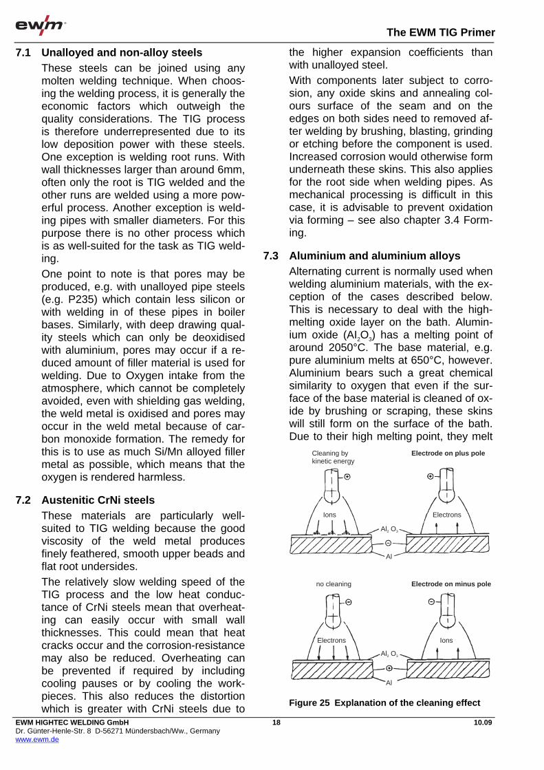
The EWM TIG Primer
EWM HIGHTEC WELDING GmbH Dr. Günter-Henle-Str. 8 D-56271 Mündersbach/Ww., Germany www.ewm.de
18 10.09
7.1 Unalloyed and non-alloy steels These steels can be joined using any molten welding technique. When choos-ing the welding process, it is generally the economic factors which outweigh the quality considerations. The TIG process is therefore underrepresented due to its low deposition power with these steels. One exception is welding root runs. With wall thicknesses larger than around 6mm, often only the root is TIG welded and the other runs are welded using a more pow-erful process. Another exception is weld-ing pipes with smaller diameters. For this purpose there is no other process which is as well-suited for the task as TIG weld-ing. One point to note is that pores may be produced, e.g. with unalloyed pipe steels (e.g. P235) which contain less silicon or with welding in of these pipes in boiler bases. Similarly, with deep drawing qual-ity steels which can only be deoxidised with aluminium, pores may occur if a re-duced amount of filler material is used for welding. Due to Oxygen intake from the atmosphere, which cannot be completely avoided, even with shielding gas welding, the weld metal is oxidised and pores may occur in the weld metal because of car-bon monoxide formation. The remedy for this is to use as much Si/Mn alloyed filler metal as possible, which means that the oxygen is rendered harmless.
7.2 Austenitic CrNi steels These materials are particularly well-suited to TIG welding because the good viscosity of the weld metal produces finely feathered, smooth upper beads and flat root undersides. The relatively slow welding speed of the TIG process and the low heat conduc-tance of CrNi steels mean that overheat-ing can easily occur with small wall thicknesses. This could mean that heat cracks occur and the corrosion-resistance may also be reduced. Overheating can be prevented if required by including cooling pauses or by cooling the work-pieces. This also reduces the distortion which is greater with CrNi steels due to
the higher expansion coefficients than with unalloyed steel. With components later subject to corro-sion, any oxide skins and annealing col-ours surface of the seam and on the edges on both sides need to removed af-ter welding by brushing, blasting, grinding or etching before the component is used. Increased corrosion would otherwise form underneath these skins. This also applies for the root side when welding pipes. As mechanical processing is difficult in this case, it is advisable to prevent oxidation via forming – see also chapter 3.4 Form-ing.
7.3 Aluminium and aluminium alloys Alternating current is normally used when welding aluminium materials, with the ex-ception of the cases described below. This is necessary to deal with the high-melting oxide layer on the bath. Alumin-ium oxide (AI2O3) has a melting point of around 2050°C. The base material, e.g. pure aluminium melts at 650°C, however. Aluminium bears such a great chemical similarity to oxygen that even if the sur-face of the base material is cleaned of ox-ide by brushing or scraping, these skins will still form on the surface of the bath. Due to their high melting point, they melt
Cleaning bykinetic energy
Ions Electrons
Electrons Ions
no cleaning
Al
Al
Al O2 3
Al O2 3
Electrode on plus pole
Electrode on minus pole
Figure 25 Explanation of the cleaning effect

The EWM TIG Primer
EWM HIGHTEC WELDING GmbH Dr. Günter-Henle-Str. 8 D-56271 Mündersbach/Ww., Germany www.ewm.de
19 10.09
partially only directly underneath the arc. The majority of the seam surface would therefore be covered with a solid layer of aluminium oxide when welding with direct current (- pole). This makes it impossible to observe the bath and makes it more difficult to include filler. This oxide layer can be removed by using flux agents, as in brazing, but this would mean additional work. With alternating current welding, there is the option of cracking open and getting rid of this oxide layer using high-energy densities in the arc. This only applies to the ions as the electrons do not have suf-ficient kinetic energy for the purpose due to their low mass. Figure 25 shows the high-energy density flow in the arc. If the minus pole is on the electrode, the electrons move from the electrode to the worpiece and the remaining ions from the workpiece to the electrode. With this po-larity, no cleaning effect is possible. With reversed polarity, on the other hand, the heavy ions hit the surface of the work-piece. The kinetic energy in these ions can crack open and eliminate the oxide skin. Welding on the hotter plus pole would mean that the current-carrying capacity of the electrode would be very low. This variant of TIG welding can therefore only be used for welding very thin aluminium structures (up to around 2.5 mm wall thickness). As a compromise, alternating current can be used. If the positive half-wave is on the electrode, the cleaning ef-fect is started. In the subsequent negative half-wave, the electrode can then cool down once more. This is therefore also known as the cleaning and cooling half-wave. The current-carrying capacity is lower when welding with alternating cur-rent than with direct current minus pole welding. However, it is significantly higher than when welding on the plus pole – see
also Table 1. It has been shown that for an adequate cleaning effect, not all the positive half-wave is required, but that just 20 or 30% of it is sufficient. This has been exploited in modern TIG power sources. These generate an artificial square-wave alternating current in which fast-reacting switches (transistorss) are used to connect the plus and minus poles of a direct current source alternately to the electrode. This means that the bal-ance of both half-waves can be changed in relation to one another, e.g. from 20% plus / 80% minus to 80% plus / 20% mi-nus (Figure 26). The lower proportion on the plus pole re-sults in a higher current-carrying capacity of the electrode or with the same current setting in an extended service life. With these “square-wave sources” the fre-quency of the artificial alternating current can normally also be changed, e.g. be-tween 50 and 300 Hz. The increase in frequency also conserves the electrode. The artificial square-wave alternating cur-rent has another advantage, however. As the current course form is very steep when the polarity is changed, the idle times of the arc are considerably shorter with the zero pass than with a sinusoidal waveform. The reignition is therefore safer, even without an igniting aid, and the arc is more stable overall. However, the reignition operations are more notice-able due to the louder humming noise. Modern TIG power sources permit weld-ing with direct current, as well as with si-nusoidal and square-wave alternating current (Figure 28). In recent times a variant of TIG minus pole welding has been used which uses shielding gas with a high helium content (e.g. 90% He / 10% Ar). When welding on the minus pole, the oxide skin cannot be cracked open, as explained above. But the high temperature of the energy-rich helium arc means that it can be liquefied. This makes it much less problematic. TIG direct current welding on the minus pole using helium is used primarily for repair welding on cast components made from
100A
100A
+Current
-
80%
80%
50%
50%
20%
20%
Figure 26 Different balance settings with square-wave alternating current

The EWM TIG Primer
EWM HIGHTEC WELDING GmbH Dr. Günter-Henle-Str. 8 D-56271 Mündersbach/Ww., Germany www.ewm.de
20 10.09
aluminium/silicon alloys due to the im-proved fusion penetration characteristics. A particular feature of welding the mate-rial aluminium is its tendency to form pores when retaining hydrogen. The con-ditions are considerably more important than when welding steel. Whereas iron still has a dissolving power for hydrogen of 8 cm3/100 g of weld metal in the transi-tion from liquid to the solid state, alumin-ium in the solid state has virtually no dissolving power for hydrogen. This means that all hydrogen taken up during welding must exit the weld metal before it embrittles. Otherwise pores will be pro-duced in the weld metal. Sources of hydrogen when TIG welding aluminium are primarily oxide skins on the parent material. These attract mois-ture and therefore need to be removed before welding by brushing or scraping. On the other hand, the arc is quieter if there is a thin oxide skin on the surface because this better emits electrons than the pure metal. This means that a com-promise needs to be found between a stable arc and sufficient resistance to po-
rosity. The best option has proved to be cleaning oxides from the workpiece sur-faces thoroughly before welding, but then waiting another one or two hours so that a thin oxide coating can form. The oxide skins formed on the surface of the filler rods also contribute to pore formation. Aluminium fillers should therefore be stored carefully and for short periods only.
7.4 Copper and copper alloys The welding of copper is more compli-cated primarily because of its high level of heat conductance. With larger panel thicknesses, the material therefore needs to be pre-heated at least at the start of the weld seam. A pre-heating effect is produced later on by the forward welding heat, which means that large-scale pre-heating is only required for wall thick-nesses > 5 mm. The TIG process pro-vides the option of using the arc itself for pre-heating, by using an extended arc in circling movements to heat the start of the weld seam. Pure copper and many Cu alloys are welded using direct current, with the elec-trode on the minus pole. Only a few bronzes such as brass and aluminium bronze are better welded with alternating current.
7.5 Other materials In addition to the materials already dis-cussed, nickel and nickel alloys are also TIG-welded to a significant extent. The
Figure 27 Using the PICOTIG 160 HF
Figure 28 TRITON 220 AC/DC, TIG inverter welding machine

The EWM TIG Primer
EWM HIGHTEC WELDING GmbH Dr. Günter-Henle-Str. 8 D-56271 Mündersbach/Ww., Germany www.ewm.de
21 10.09
most important are nickel/chrome alloys (e.g. Inconel) and nickel/copper alloys (e.g. Monel). Titanium and titanium alloys are also TIG-welded. Direct current with a negative poled electrode is also best suited to these materials. When welding titanium, however, not only the welding seam area itself should be protected by shielding gas but to prevent annealing colour shielding gas should also be added at a great distance from the weld-ing point and where applicable also on the back using a gas trailer. Otherwise the material will become brittle due to the take-up of atmospheric gases.
8 Applications for TIG welding Example applications for TIG welding are given in Figure 27 to Figure 32. The TIG process is used primarily to join thin-walled workpieces; for thicker materials generally only the root pass is welded us-ing this process and the filler and final passes carried out using other more powerful techniques. Irrespective to one statistic, the percentage of this process is just below 2% based on the total of all welding seams produced in Germany. However, this figure comes out particu-larly unfavourably for TIG welding be-cause it is based on the consumption of filler material. As already mentioned, TIG welding normally uses little filler material. The actual proportion of this process could therefore well be greater, although not approaching the use of manual arc welding at around 7.5%. Nevertheless,
TIG welding is a very important process. Its advantages have been described in a different section of this publication.
8.1 Uses in manufacturing TIG welding is used primarily in the manufacture of boilers, containers, equipment and pipes, but also in the aerospace and space industry and for the production of stainless steel longitudinal seam welded pipes. A further application of TIG welding lies in GMA surfacing, particularly in tool manu-facture where this process can be used to improve even very fine contours, e.g. on dies and blanking dies.
8.2 Example applications Figure 29 shows the use of manual TIG welding in equipment construction. A flange is welded into a housing made from stainless CrNi steel (material num-ber 1.4301). The TRITON 160 DC weld-ing system being used supplies direct current up to 160 amperes at a duty cycle of 50%. Similarly, the application shown in Figure 30 is the welding of CrNi steel in the chemical industry.
Figure 29 TRITON 160 DC, TIG welding in equipment construction
Figure 30 TRITON 260 DC, TIG welding on pipes
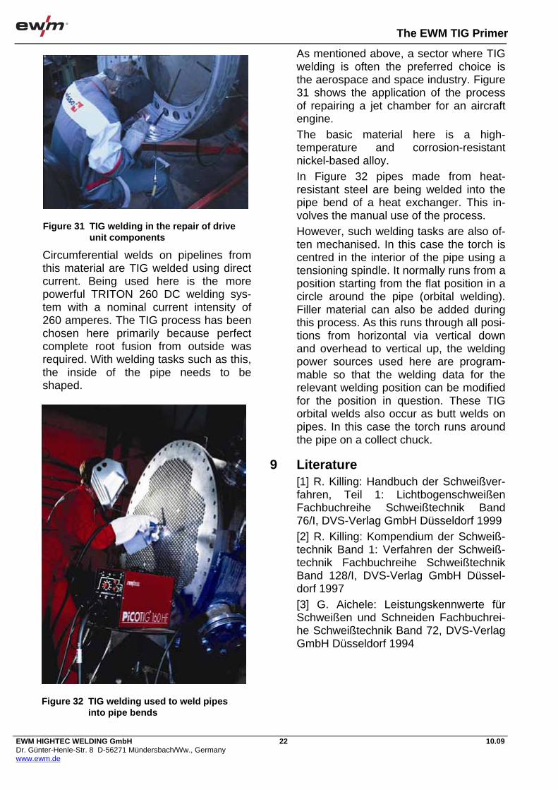
The EWM TIG Primer
EWM HIGHTEC WELDING GmbH Dr. Günter-Henle-Str. 8 D-56271 Mündersbach/Ww., Germany www.ewm.de
22 10.09
Circumferential welds on pipelines from this material are TIG welded using direct current. Being used here is the more powerful TRITON 260 DC welding sys-tem with a nominal current intensity of 260 amperes. The TIG process has been chosen here primarily because perfect complete root fusion from outside was required. With welding tasks such as this, the inside of the pipe needs to be shaped.
As mentioned above, a sector where TIG welding is often the preferred choice is the aerospace and space industry. Figure 31 shows the application of the process of repairing a jet chamber for an aircraft engine. The basic material here is a high-temperature and corrosion-resistant nickel-based alloy. In Figure 32 pipes made from heat-resistant steel are being welded into the pipe bend of a heat exchanger. This in-volves the manual use of the process. However, such welding tasks are also of-ten mechanised. In this case the torch is centred in the interior of the pipe using a tensioning spindle. It normally runs from a position starting from the flat position in a circle around the pipe (orbital welding). Filler material can also be added during this process. As this runs through all posi-tions from horizontal via vertical down and overhead to vertical up, the welding power sources used here are program-mable so that the welding data for the relevant welding position can be modified for the position in question. These TIG orbital welds also occur as butt welds on pipes. In this case the torch runs around the pipe on a collect chuck.
9 Literature [1] R. Killing: Handbuch der Schweißver-fahren, Teil 1: Lichtbogenschweißen Fachbuchreihe Schweißtechnik Band 76/I, DVS-Verlag GmbH Düsseldorf 1999 [2] R. Killing: Kompendium der Schweiß-technik Band 1: Verfahren der Schweiß-technik Fachbuchreihe Schweißtechnik Band 128/I, DVS-Verlag GmbH Düssel-dorf 1997 [3] G. Aichele: Leistungskennwerte für Schweißen und Schneiden Fachbuchrei-he Schweißtechnik Band 72, DVS-Verlag GmbH Düsseldorf 1994
Figure 31 TIG welding in the repair of drive unit components
Figure 32 TIG welding used to weld pipes into pipe bends
The EWM TIG Primer
EWM HIGHTEC WELDING GmbH Dr. Günter-Henle-Str. 8 D-56271 Mündersbach/Ww., Germany www.ewm.de
23 10.09
10 Imprint The TIG Primer, 3rd edition 2009 From the EWM Knowledge range of pub-lications – All about welding All rights reserved. Reprinting, including extracts, is forbid-den. No part of this brochure may be re-produced or electronically procssed, reproduced or distributed in any form (photocopy, microfilm or any other proce-dure) without the written permission of EWM. © EWM HIGHTEC WELDING GmbH Dr.-Günter-Henle-Str. 8
D-56271 Mündersbach, Germany Phone: +49(0)2680.181-0 Fax: +49(0)2680.181-244 mailto:[email protected] http://www.ewm.de

MIG/MAG PRIMER

The EWM MIG/MAG Primer
The innovative coldArc® technology for manual and automated applications
Can be used in any position • Excellent arc controllability for positional welding• Reduced weld seam prepa- ration work – greater fi t up tolerances
Excellent gap bridging when welding root passes• No excessive root build-up, even in horizontal position• Good fl ank capture even with offset edges• No wire piercing• No un-welded wire deposits• For thin panels and root welds, e.g. PC position
Virtually spatter-free process • Digitally controlled, virtually powerless material transfer• Reduced prep and post weld work• Ideal for visible seams – fi ni- shing work becomes unneces- sary
coldArc® + forceArc®- combination in one machine• Root welding with coldArc®: full control of the droplet transfer, minimised risk of bonding faults, spatter-free welding• Layer build-up with forceArc®: best possible penetration properties, result: an effi cient weld with perfect properties
coldArc® – The “low-energy” short circuit arc for welding and brazingThe special method of joining thin panels or welding root passes, steel, chrome/nickel, aluminium as well as mixed joints. coldArc® masters also large air gaps in all positions.
coldArc® + forceArc®
Perfect alone, together unbeatableTwo innovative welding processes, one alpha Q power source, all
welded joints: coldArc®, the specialist for perfect and secure root welds, forceArc® for high levels of effi ciency when wel-ding the fi ll and capping runs.
The innovative coldArc® technology for manual and automated applications Secure joints with reduced heat transfer
HIGHLIGHTS
Reduced heat transfer • Low distortion and minimal heat-affected zones – perfect for CrNi, high strength steels and thin panels
The best for welding and brazing• Steel, zinc-plated steel, CrNi, aluminium and mixed joints
Universal in all positions• All positional joining tasks – vertical down, vertical up and overhead welds
Start saving immediately by reducing your joint preparation costs• Excellent gap bridging on thin panels, and root passes in plate or pipework applications
Minimize your post weld work• Virtually spatter-free – close to TIG fi nish, excellent formation of root and capping runs, no undercut
Excellent gap bridging when brazing sheet metal • No excessive build up• Good fl ank and edge capture• For thin panels and root passes
Heat-reduced brazing with innovative, low melting point, zinc-based solders• No damage to the zinc coating• Excellent corrosion resistance• Minimum distortion• Alternative to Cu-based alloys, with comparable strength
Reduced heat transfer• Reduced gap transformation• Less distortion• Minimised heat-affected zones• Reduced annealing discoloura- tion and scaling• Ideal for CrNi and high-strength steels
Optimal energy and resource effi ciency• Savings on materials, gas, ener- gy and wage costs• Seam geometry can be infl u- enced individually• Effi cient joining: smaller, nar- rower welds• Reduced requirements for weld pool backing• Long service life for spare and replacement parts
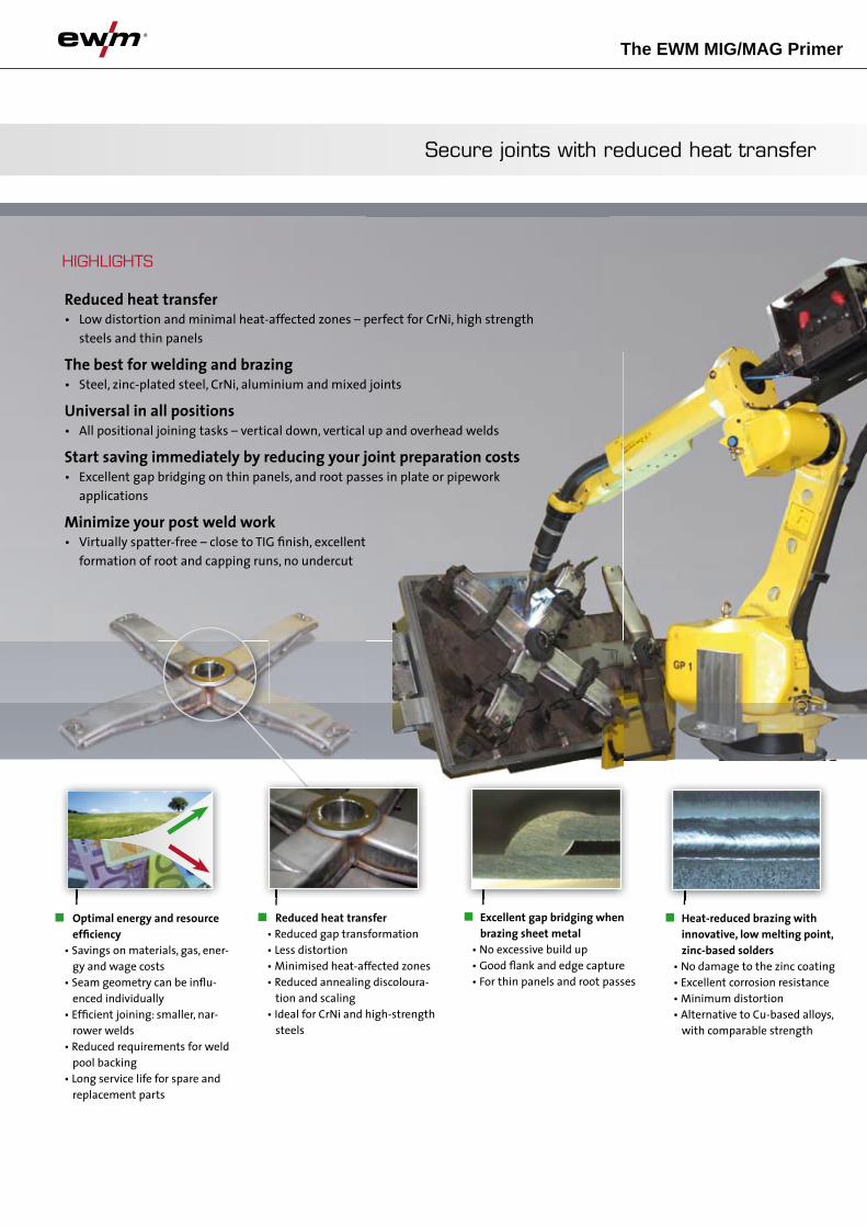

The EWM MIG/MAG Primer
With forceArc® you can weld more economically, with better quality, and optimise your work processes! This combi-nation of savings on materials, power and wage costs results in a noticeable reduc-tion in manufacturing costs. All this means a rapid, calculable amortisation of your welding machines.
• Very narrow high pressure arc – with deep fusion penetration and excellent root and edge formation
• Exceptional directional arc stability – for welding when extended wire stick-out lengths are required
• Excellent seam quality – virtually spatter- free, no undercuts and minimised heat- affected zone
HIGHLIGHTS
The innovative forceArc® technology for manual and mechanised applications
Smaller edge preparation angles – fewer layers • High potential for savings• Minimised weld seam prepa- ration• Fewer layers• Less fi ller material and shiel- ding gas consumption• Greatly reduced welding time• Elimination of the weld sup- port in most cases, when used to replace submerged arc welding
No seam preparation – full connection • No time needed for edge preparation• Full connection without edge preparation• Full connection: single layer welding – without the backing run normally required Particularly advantageous, for example if due to corrosion risks, a backing run is normally required, useable over a large range of material thicknesses, extremely advantageous for thicker panels
Small heat-affected zones due to narrow and concentrated arc • Less material distortion thanks to reduced heat input• Reduced intermediate layer temperatures and minimised joint distortion Particularly advantageous, e.g. when welding fi ne- grained steels
Prevention of undercuts • Exceptional seam quality, e.g. with fi llet welds• Optimal seam geometry Particularly advantageous, e.g. with dynamically loaded com - ponents
• Optimised weld seam design modifi ed for the process – reduced seam volume due to smaller included angles for the edge preparation, and in some cases, total elimination of edge preparation
• Cost-effective standard accessories and welding materials – no exotic torches, gases or welding consumables are required
• Lower manufacturing costs for the entire joining process – reduction in preparation and fi nishing work as well as cost savings for wages, welding materials, gas and electrical energy
• Signifi cant time savings create increased manufacturing capaci- ties for new contracts – increase turnover and shorten delivery times
• Standard in all alpha Q and Phoenix welding machines for manual, mechanised and automated applications
• Additional cost-saving potential when using the EWM MT torch thanks to extended service life for EWM torches due to the use of highest quality, self designed components. This naturally applies to spare and replaceable parts as well.
The innovative forceArc® technology for manual and mechanised applications Weld more economically, with better quality and increased effectiveness
Directionally stable, smooth arc• Even in tight and narrow joints• No arc blow onto the material fl anks, even with long wire stickout lengths up to 40 mm • Fast and dynamic regulation of arc length and direction caused by changes in wire stickout length Particularly advantageous, e.g. for very narrow joints and fi llet welds
Quality, load capacity, opera- ting safety • Homogeneous seam structure• Optimal seam geometry• Undercut-free, no pores, reduc- tion in welding failures and cold laps
Economic – virtually spatter- free welding • Thanks to machine technology with highly dynamic control technology• Compatible with different materials and shielding gases • Smooth seam surface – e.g. for simple coating • Reduction of additional prepa- ration and fi nishing work, reduction in wear and tear of fi nishing materials, offering very high potential for savings
Secure root formation with the ideal seam geometry • Particularly deep penetration and therefore possible reduc- tion of the throat thickness or seam cross-section• Higher process safety – simple, safe handling• High process security, main- tain penetration irrespective of changes in torch angle/dis- tance Particularly advantageous, e.g. with very narrow joints and fi l- let welds as well as dynamical- ly loaded components and hard to reach areas


The EWM MIG / MAG Primer
EWM HIGHTEC WELDING GmbH
Dr. Günter-Henle-Str. 8 D-56271 Mündersbach/Ww., Germany
www.ewm.de
1 10.09
Contents
Contents...........................................................................................................................................................1
1 Preface..........................................................................................................................................................2
2 The process ..................................................................................................................................................2 2.1 General ...............................................................................................................................................2 2.2 Current type ........................................................................................................................................3
3 Fillers and auxiliary materials........................................................................................................................3 3.1 Types of wire electrodes.....................................................................................................................3 3.2 Welding-engineering delivery conditions for wire electrodes and cored wire electrodes ...................4 3.3 Shielding gases...................................................................................................................................5 3.4 Weld metal properties.........................................................................................................................6
4 Groove preparation .......................................................................................................................................7 4.1 Groove shapes....................................................................................................................................7 4.2 Placement of the weld groove side walls............................................................................................7 4.3 Backing ...............................................................................................................................................8 4.4 Forming...............................................................................................................................................8
5 Welding machines.........................................................................................................................................9 5.1 Power sources ....................................................................................................................................9 5.2 Wire feed units ..................................................................................................................................11 5.3 Tube package and torch ...................................................................................................................12 5.4 Control ..............................................................................................................................................13
6 Material transfer with MIG/MAG welding ....................................................................................................14 6.1 Arc ranges.........................................................................................................................................14 6.2 Short arc ...........................................................................................................................................14 6.3 Long arc ............................................................................................................................................15 6.4 Spray arc...........................................................................................................................................15 6.5 Mixed arc ..........................................................................................................................................16 6.6 Pulse arc ...........................................................................................................................................16 6.7 Special types of material transfer .....................................................................................................16
7 Setting the set welding parameters.............................................................................................................17 7.1 Setting with conventional systems....................................................................................................17 7.2 Synergetic setting of set welding parameters...................................................................................18 7.3 Regulating the MIG/MAG process ....................................................................................................19
8 Performing welding work.............................................................................................................................19 8.1 Igniting the arc ..................................................................................................................................19 8.2 Moving the torch ...............................................................................................................................20 8.3 Ending the welding process..............................................................................................................20 8.4 Welding parameters..........................................................................................................................20 8.5 Automation options ...........................................................................................................................22
9 Work safety .................................................................................................................................................23
10 24
10 Special features of different materials.........................................................................................................24 10.1 Un-alloyed and low-alloy steels ........................................................................................................24 10.2 High-alloy steels and nickel-based alloys.........................................................................................24 10.3 Aluminium and aluminium alloys ......................................................................................................25 10.4 Other materials .................................................................................................................................26
11 Applications for MIG / MAG welding ...........................................................................................................26 11.1 Uses in manufacturing ......................................................................................................................26 11.2 Example applications........................................................................................................................26
12 Literature .....................................................................................................................................................27
13 Imprint .........................................................................................................................................................27
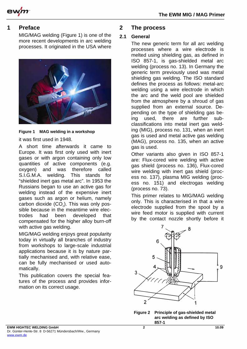
The EWM MIG / MAG Primer
EWM HIGHTEC WELDING GmbH Dr. Günter-Henle-Str. 8 D-56271 Mündersbach/Ww., Germany www.ewm.de
2 10.09
1 Preface MIG/MAG welding (Figure 1) is one of the more recent developments in arc welding processes. It originated in the USA where
it was first used in 1948. A short time afterwards it came to Europe. It was first only used with inert gases or with argon containing only low quantities of active components (e.g. oxygen) and was therefore called S.I.G.M.A. welding. This stands for “shielded inert gas metal arc”. In 1953 the Russians began to use an active gas for welding instead of the expensive inert gases such as argon or helium, namely carbon dioxide (CO2). This was only pos-sible because in the meantime wire elec-trodes had been developed that compensated for the higher alloy burn-off with active gas welding. MIG/MAG welding enjoys great popularity today in virtually all branches of industry from workshops to large-scale industrial applications because it is by nature par-tially mechanised and, with relative ease, can be fully mechanised or used auto-matically. This publication covers the special fea-tures of the process and provides infor-mation on its correct usage.
2 The process 2.1 General
The new generic term for all arc welding processes where a wire electrode is melted using shielding gas, as defined in ISO 857-1, is gas-shielded metal arc welding (process no. 13). In Germany the generic term previously used was metal shielding gas welding. The ISO standard defines the process as follows: metal-arc welding using a wire electrode in which the arc and the weld pool are shielded from the atmosphere by a shroud of gas supplied from an external source. De-pending on the type of shielding gas be-ing used, there are further sub-classifications into metal inert gas weld-ing (MIG), process no. 131, when an inert gas is used and metal active gas welding (MAG), process no. 135, when an active gas is used. Other variants also given in ISO 857-1 are: Flux-cored wire welding with active gas shield (process no. 136), Flux-cored wire welding with inert gas shield (proc-ess no. 137), plasma MIG welding (proc-ess no. 151) and electrogas welding (process no. 73). This primer relates to MIG/MAG welding only. This is characterised in that a wire electrode supplied from the spool by a wire feed motor is supplied with current by the contact nozzle shortly before it
Figure 1 MAG welding in a workshop
Figure 2 Principle of gas-shielded metal arc welding as defined by ISO 857-1

The EWM MIG / MAG Primer
EWM HIGHTEC WELDING GmbH Dr. Günter-Henle-Str. 8, D-56271 Mündersbach/Ww., Germany www.ewm.de
3 10.09
leaves the torch so that the arc can burn between the end of the wire electrode and the workpiece. The shielding gas flows out of the shielding gas nozzle, which covers the wire electrode concen-trically (Figure 2). This shields the weld metal from being penetrated by the atmospheric gases oxygen, hydrogen and nitrogen. The shielding gas has other purposes in addi-tion to its protective function. As it deter-mines the composition of the arc atmosphere, it also affects its electrical conductance and thus the welding char-acteristics. It also affects with pick-up and burn-off processes and the chemical composition of the weld metal produced - in other words, it also has a metallurgic effect.
2.2 Current type Apart from more recent exceptions, MIG/MAG welding is normally performed using direct current, with the plus pole of the power source on the electrode and the minus pole on the workpiece. With some cored wire the reverse polarity is also sometimes used. In more recent times alternating current is also used for very special applications, e.g. for MIG welding on very thin panels.
3 Fillers and auxiliary materials 3.1 Types of wire electrodes
Wire electrodes for MIG/MAG welding of unalloyed steels and fine-grained con-structional steels are defined in
DIN EN 440. The standard differentiates between the chemical compositions of 11 types of welding wires. It also contains welding wire types commonly used in other European countries. In Germany only types G2Si1, G3Si1 and G4Si1 (given in Table 1 for unalloyed steels) are used in any quantity. These contain in-creasing amounts of silicon and manga-nese in the order given, with an average of 0.65 to 0.9 % of silicon and 1.10 to 1.75 % of manganese. For fine-grained steels, the types G4Mo, G3Ni1 and G3Ni2 are also used (Figure 3). Cored wire electrodes for welding these types of steel are given in DIN EN 758. Depending on the composition of the fill-ing, a distinction is made here between rutile types, basic types and metal pow-der types. In addition to cored wires for MIG/MAG welding, DIN EN 758 also de-fines self-shielding cored wires, which can be used for welding without the addi-tion of any shielding gas. They are com-monly used for GMA-surfacing (Figure 4). Wire electrodes for welding creep resis-tant steels are defined in DIN EN 12070, and cored wire electrodes for these steels in DIN EN 12071. The wire electrodes range from molybdenum alloy only vari-ant to wires with 1, 2.5, 5 and 9 % chrome to wire electrodes with 12 % chrome. Other alloy elements are molyb-denum, vanadinite and tungsten. There are cored wire electrodes with up to 5 % chrome.
Figure 3 Welding fine-grained constructional steels in crane construction work
Figure 4 Hard-facing of spiral conveyors
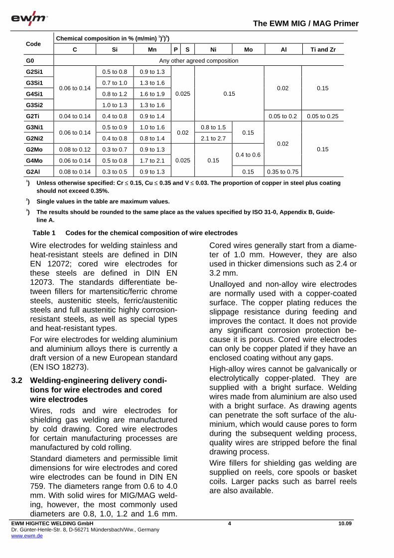
The EWM MIG / MAG Primer
EWM HIGHTEC WELDING GmbH Dr. Günter-Henle-Str. 8, D-56271 Mündersbach/Ww., Germany www.ewm.de
4 10.09
Wire electrodes for welding stainless and heat-resistant steels are defined in DIN EN 12072; cored wire electrodes for these steels are defined in DIN EN 12073. The standards differentiate be-tween fillers for martensitic/ferric chrome steels, austenitic steels, ferric/austenitic steels and full austenitic highly corrosion-resistant steels, as well as special types and heat-resistant types. For wire electrodes for welding aluminium and aluminium alloys there is currently a draft version of a new European standard (EN ISO 18273).
3.2 Welding-engineering delivery condi-tions for wire electrodes and cored wire electrodes Wires, rods and wire electrodes for shielding gas welding are manufactured by cold drawing. Cored wire electrodes for certain manufacturing processes are manufactured by cold rolling. Standard diameters and permissible limit dimensions for wire electrodes and cored wire electrodes can be found in DIN EN 759. The diameters range from 0.6 to 4.0 mm. With solid wires for MIG/MAG weld-ing, however, the most commonly used diameters are 0.8, 1.0, 1.2 and 1.6 mm.
Cored wires generally start from a diame-ter of 1.0 mm. However, they are also used in thicker dimensions such as 2.4 or 3.2 mm. Unalloyed and non-alloy wire electrodes are normally used with a copper-coated surface. The copper plating reduces the slippage resistance during feeding and improves the contact. It does not provide any significant corrosion protection be-cause it is porous. Cored wire electrodes can only be copper plated if they have an enclosed coating without any gaps. High-alloy wires cannot be galvanically or electrolytically copper-plated. They are supplied with a bright surface. Welding wires made from aluminium are also used with a bright surface. As drawing agents can penetrate the soft surface of the alu-minium, which would cause pores to form during the subsequent welding process, quality wires are stripped before the final drawing process. Wire fillers for shielding gas welding are supplied on reels, core spools or basket coils. Larger packs such as barrel reels are also available.
Chemical composition in % (m/min) 1)2)3) Code
C Si Mn P S Ni Mo Al Ti and Zr
G0 Any other agreed composition
G2Si1 0.5 to 0.8 0.9 to 1.3
G3Si1 0.7 to 1.0 1.3 to 1.6
G4Si1 0.8 to 1.2 1.6 to 1.9
G3Si2
0.06 to 0.14
1.0 to 1.3 1.3 to 1.6
0.02 0.15
G2Ti 0.04 to 0.14 0.4 to 0.8 0.9 to 1.4
0.025 0.15
0.05 to 0.2 0.05 to 0.25
G3Ni1 0.5 to 0.9 1.0 to 1.6 0.8 to 1.5
G2Ni2 0.06 to 0.14
0.4 to 0.8 0.8 to 1.4 0.02
2.1 to 2.7 0.15
G2Mo 0.08 to 0.12 0.3 to 0.7 0.9 to 1.3
G4Mo 0.06 to 0.14 0.5 to 0.8 1.7 to 2.1 0.4 to 0.6
0.02
G2Al 0.08 to 0.14 0.3 to 0.5 0.9 to 1.3
0.025 0.15
0.15 0.35 to 0.75
0.15
1) Unless otherwise specified: Cr 0.15, Cu 0.35 and V 0.03. The proportion of copper in steel plus coating should not exceed 0.35%.
2) Single values in the table are maximum values. 3) The results should be rounded to the same place as the values specified by ISO 31-0, Appendix B, Guide-
line A.
Table 1 Codes for the chemical composition of wire electrodes

The EWM MIG / MAG Primer
EWM HIGHTEC WELDING GmbH Dr. Günter-Henle-Str. 8, D-56271 Mündersbach/Ww., Germany www.ewm.de
5 10.09
3.3 Shielding gases Shielding gases for MIG/MAG welding can be found in DIN EN 439. This stan-dard defines all shielding gases for arc welding and arc cutting. The shielding gases are divided into 7 groups and fur-ther sub-groups (Table 2). Group R includes argon/hydrogen mix-tures, which have a reducing effect. The gases in group R1 are used for TIG weld-ing and for plasma welding, along with argon and helium, whereas the gases in subgroup 2 with a higher hydrogen con-tent (H) are used for plasma cutting and for root protection (forming gases). Group I includes the inert gases, includ-ing argon (Ar) and helium (He), as well as
argon/helium mixtures. They are used for TIG, MIG, and plasma welding, and for root protection. The large M group, which is divided into subgroups M1, M2 and M3, contains the mixed gases used for MAG welding. Each subgroup also contains 3 or 4 fur-ther subgroups. The gases are arranged from M1.1 to M3.3 depending on their oxidation properties, i.e. M1.1 is only slightly oxidising and M3.3 has the high-est level of oxidisation. The main compo-nent of these gases is argon, and the active components added are oxygen (O) or carbon dioxide (CO2) or oxygen and carbon dioxide (three-component gases). In the range of gases used for MAG weld-
Code 1) Components in volumetric percent
Oxidising Inert Reducing Slow
reacting Group No.
CO2 O2 Ar He H2 N2
Normal
application Notes
1 > 0 to 15
R 2
Residual 2) > 15 to 35
TIG, plasma weld-
ing, plasma cutting,
root protection
1 100
2 100 I
3
Residual > 0 to
95
MIG, TIG, plasma
welding, root pro-
tection
inert
1 > 0 to 5
2 > 0 to 5
3 M1
4 > 0 to 5 > 0 to 3
low oxidi-
sation
1 > 5 to 25
2
3 > 0 to 5 > 3 to 10 M2
4 > 5 to 25 > 0 to 8
1 > 25 to 50
2 > 10 to 15 M3
3 > 5 to 50 > 8 to 15
Residual 2)
1 100 C
2 Residual > 0 to 30
MAG
high oxidi-
sation
1 100 slow to
react F
2
> 0 to 50 Residual
Plasma cutting,
root protection reducing
1) If components not given in the table are added, the gas mixture is designated as a special gas and marked with the
letter S. More information on the designation S is given in section 4.
2) Argon can be replaced with helium up to 95%. The helium percentage is indicated by an additional code irrespective to
Table 5, see section 4.
Table 2 Classification of shielding gases for arc welding and arc cutting (EN 439: 1994)
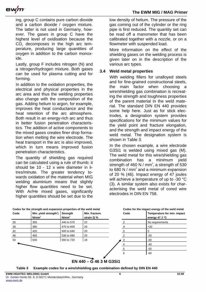
The EWM MIG / MAG Primer
EWM HIGHTEC WELDING GmbH Dr. Günter-Henle-Str. 8, D-56271 Mündersbach/Ww., Germany www.ewm.de
6 10.09
ing, group C contains pure carbon dioxide and a carbon dioxide / oxygen mixture. The latter is not used in Germany, how-ever. The gases in group C have the highest level of oxidisation because the CO2 decomposes in the high arc tem-perature, producing large quantities of oxygen in addition to the carbon monox-ide. Lastly, group F includes nitrogen (N) and a nitrogen/hydrogen mixture. Both gases can be used for plasma cutting and for forming. In addition to the oxidation properties, the electrical and physical properties in the arc area and thus the welding properties also change with the composition of the gas. Adding helium to argon, for example, improves the heat conductance and the heat retention of the arc atmosphere. Both result in an energy-rich arc and thus in better fusion penetration characteris-tics. The addition of active components to the mixed gases creates finer drop forma-tion when melting the wire electrode. The heat transport in the arc is also improved, which in turn means improved fusion penetration characteristics. The quantity of shielding gas required can be calculated using a rule of thumb; it should be 10 - 12 x wire diameter in li-tres/minute. The greater tendency to-wards oxidation of the material when MIG welding aluminium means that slightly higher flow quantities need to be set. With Ar/He mixed gases, significantly higher quantities should be set due to the
low density of helium. The pressure of the gas coming out of the cylinder or the ring pipe is first reduced. The quantity set can be read off a manometer that has been calibrated together with a nozzle, or on a flowmeter with suspended load. More information on the effect of the shielding gases on the welding process is given later on in the description of the various arc types.
3.4 Weld metal properties With welding fillers for unalloyed steels and for fine-grained constructional steels, the main factor when choosing a wire/shielding gas combination is recreat-ing the strength and toughness properties of the parent material in the weld mate-rial. The standard DIN EN 440 provides some help here. Just as for stick elec-trodes, a designation system provides specifications for the minimum values for the yield point and fracture elongation, and the strength and impact energy of the weld metal. The designation system is shown in Table 3. In the chosen example, a wire electrode G3Si1 is welded using mixed gas (M). The weld metal for this wire/shielding gas combination has a minimum yield strength of 460 N / mm2, a strength of 530 to 680 N / mm2 and a minimum expansion of 20 % (46). Impact energy of 47 joules will achieve a temperature of up to -30 °C (3). A similar system also exists for char-acterising the weld metal of cored wire electrodes in DIN EN 758.
Codes for the strength and expansion properties of the weld metal Codes for the impact energy of the weld metal
Code Min. yield strength1)
N/mm2
Strength
N/mm2
Min. fracture
strain 2) %
Code Temperature for min. impact
energy 47 J °C
35 355 440 to 570 22 Z No requirements
38 380 470 to 600 20 A +20
42 420 500 to 640 20 0 0
46 460 530 to 680 20 2 -20
50 500 560 to 720 18 3 -30
4 -40
5 -50
6 -60
EN 440 – G 46 3 M G3Si1
Table 3 Example codes for a wire/shielding gas combination defined by DIN EN 440

The EWM MIG / MAG Primer
EWM HIGHTEC WELDING GmbH Dr. Günter-Henle-Str. 8, D-56271 Mündersbach/Ww., Germany www.ewm.de
7 10.09
With creep resistant steels, corrosion-resistant and heat-resistant steels and with aluminium materials, the general rule is that to achieve the necessary material properties, the weld metal needs to be of as similar type as possible or with slightly more alloy. For wire electrodes and cored wire electrodes for welding creep resis-tant, corrosion-resistant and heat-resistant steels, details are given on the minimum values for yield strength, strength, expansion and impact energy of the weld metal in the relevant standards as tables. These values do not form part of the designation system, however. A wire electrode for MAG welding creep-resistant steel 13 CrMo 4.5 has the des-ignation as defined in DIN EN 12070: EN 12070 - G CrMo1Si A wire electrode for MAG welding corro-sion-resistant CrNi steel with material number 1.4302 has the following desig-nation as defined in DIN EN 12072: EN 12072 - G 19 9 L The designation for a wire electrode for MIG welding material AlMg 5 is: EN 18273 - G RAlMg5Mn
4 Groove preparation 4.1 Groove shapes
The most important groove shapes used in MAG welding on steel are shown in Figure 5. Due to the good fusion penetration char-acteristics the process offers, seams with root faces (square, single-V, double-V welds) can be welded with complete fu-sion and without gouging on greater panel thicknesses than with manual arc welding. Gouging from the underside is recommended, however, with larger ma-terial thicknesses, to avoid faults. The root face height depends on the current intensity being used. Larger weld preparation angles (70 - 90 °) are recommended with aluminium mate-rials for larger thicknesses due to the greater heat carry-off.
4.2 Placement of the weld groove side walls With unalloyed and low-alloy steels, the edges of parts to be joined are normally prepared by oxygen cutting. High-alloy steels and metals that can be MIG/MAG welded (e.g. aluminium) can be fusion cut using a plasma arc. It is not necessary to remove the oxide skins formed during the thermal separation, but may be required in some circumstances. The special fea-tures of aluminium as a material in this respect are covered in another section. Joint type Workpiece thick-
ness (mm) Diagram
Square weld One-sided 3-8 both sides <8
Single-V weld One-sided 3-10 with backing run 3-40
Single-V butt weld with broad root face
One-sided 5-40 with backing run >10
Double-V butt weld
Both sides > 10
Single-U butt weld
One-sided > 12 with backing run >12
Single-V butt weld
One-sided 3-10 with backing run 3-30
Fillet weld T-joint
One-sided >2
Fillet weld corner joint
One-sided >2 both sides > 3
Fillet weld lap joint
One-sided >2
Fillet weld, double fillet weld
Both sides > 2
Figure 5 Groove shapes as defined in DIN EN 29692 – ISO 9692

The EWM MIG / MAG Primer
EWM HIGHTEC WELDING GmbH Dr. Günter-Henle-Str. 8, D-56271 Mündersbach/Ww., Germany www.ewm.de
8 10.09
If there are any particular requirements for observing lower tolerances, mechani-cal undercutting of the edges of parts to be joined could be advisable. This applies in particular to circumferential welds. The modern options for cutting with an elec-tron beam or a laser beam are provided in automated production.
4.3 Backing Whereas in manual welding the welder watches the progress of the weld and can achieve an even root weld even if the root opening is uneven by setting the correct current intensity, adjusting the position of the arc in the groove and the welding speed in fully automated welding every-thing must be correct from the chosen welding groove the root opening set to the correct set welding parameters and the continuous quantity of filler wire added. Backing runs are therefore often used with machine welding to simplify the root welding (Figure 6). If there is no significant variation in the root gap, root faces can also be used as natural backings, e.g. with square edge and single-V seams (internal backings). Depending on the root face height, the set welding parameters for welding the first pass need to be selected so that the root face is not fully melted. The remain-der of the root face can then be created when welding the backing run, with or without gouging. Artificial (external) backings consist of metals, for example, with most metals and alloys, of copper, and with alumin-ium, which has a low melting point, of stainless steel. Ceramic backing plates are also used in welding for this purpose. The backing plate should prevent the
spontaneous sagging of the weld metal, e.g. at points where the gap is slightly wider, so that the molten metal is caught and a root bead can be produced. The backing also forms the underside of the root weld. For this purpose a groove is therefore generally created for it.
4.4 Forming This is the extra addition of shielding gas to the back of the root where the material being welded is also in a molten state, but is not reached by the shielding gas supplied to the top side. Unlike TIG weld-ing where because of the relatively low welding speed the back of the root often has a “burnt” appearance due to oxida-tion that should be prevented by the form-ing gas, MIG/MAG welding does not require this forming gas for this reason. Thanks to the forming process, the for-mation of oxide skins and annealing col-ours on the back of the root is also prevented, or at least reduced. This is important when welding corrosion-resistant steels, for example, because these oxide skins impair the corrosion-resistance of the weld. These skins need to be removed by brushing, blasting or etching. The best option is to prevent these skins occurring in the first place by using the forming process. When welding pipes, the ends can simply be blocked and the forming gas fed into the interior. When welding metal panels, the forming gas can be allowed to flow out of openings in the backing bars. Ar-gon or an argon/hydrogen mixture can be used as the forming gas. In many cases, however, the more cost-effective forming gases in group F in DIN EN 439 can be used. These gases may consist of a hy-drogen/nitrogen mixture, for example. In some circumstances, pure nitrogen can also be used for forming.
Internal backing root face
Square edge root face Single-V joint
External backing
Single-V butt weld on Cu rail
Figure 6 Backings with machine welding

The EWM MIG / MAG Primer
EWM HIGHTEC WELDING GmbH Dr. Günter-Henle-Str. 8 D-56271 Mündersbach/Ww., Germany www.ewm.de
9 10.09
5 Welding machines Machines for MIG/MAG welding consist of the power source, the control and the wire feed unit with tube package and torch. For various applications, these can be used as compact machines or as uni-versal machines. With compact machines (Figure 7) the power source, control and wire feed unit are housed in a casing. The operation radius corresponds to the length of the torch tube package. De-pending on the wire electrode diameter being used, this is 3-5m. Irrespectively, compact machines are used mainly at fixed workstations, e.g. in welding booths or on production lines. With universal machines (Figure 8), also known as de-compact machines, the wire feed is housed separately in a case and con-nected to the power source and the con-trol using a link cable. These machines can be moved to the workpiece, which means that the opera-tion radius is 10 to 20 m larger in com-parison to the compact machine. Universal machines are therefore gener-ally used at mobile workstations and on construction sites.
5.1 Power sources The power source has the task of supply-ing the welding process with the electrical energy required. This includes reducing
the high voltage from the mains and sup-plying the high current intensity required, even if a short-circuit occurs. As with MIG/MAG welding, apart from a few re-cent developments, only direct current is used, rectifiers and inverters are used as power sources. Power sources for
Figure 7 Gas cooled compact machine SATURN 301
Figure 8 Water cooled universal machine WEGA 401
Figure 9 Inverter multiprocess machine PHOENIX

The EWM MIG / MAG Primer
EWM HIGHTEC WELDING GmbH Dr. Günter-Henle-Str. 8, D-56271 Mündersbach/Ww., Germany www.ewm.de
10 10.09
MIG/MAG welding have a horizontal or slightly falling characteristic (constant voltage characteristic). This is required to permit the process to be regulated inter-nally. More information on this will be re-quired later on. For machines to be used as multiprocess systems, the characteris-tic can also be adjusted from vertical fal-ling to horizontal. The welding rectifier consists of the trans-former and downstream rectifier stacks. Whereas the transformer converts the high voltage and low current intensity from the mains supply into welding cur-rent with low voltage and high current in-tensity, the rectifier stacks rectify the alternating current coming from the trans-former. To meet the special requirements of different welding tasks, the power sources need to be adjustable. With sim-ple machines for MIG/MAG welding, this occurs via a primary-side turn tapping us-ing step switches. Figure 10 shows the functioning principle of a step switch ma-chine. Adding more or fewer turns on the pri-mary coil changes the transmission ratio of the transformer and thus the voltage on the secondary side. With more com-
plex power sources, the current is set in the rectifier part using controllable rectifi-ers (thyristors). A scheme of a system of this type is given in Figure 11. By adjusting the thyristors as appropriate, more or fewer parts of the a.c. half-waves are allowed through, changing the weld-ing voltage. More demanding MIG/MAG machines are equipped with inverters as power sources. The inverter is an electronic power source. After a period of using analogue, secondary clocked and primary clocked electronic power sources, devel-opment has now focussed on primary clocked devices, which work in a com-pletely different way to conventional power sources (Figure 12). The current coming from the mains is first rectified and then, in order to transform it, chopped into short sections by switching on and off. This process is known as clocking. This is possible, thanks to fast-reacting electronic switches called tran-sistorss. The first transistorsised inverters used a clock frequency of around 25 kHz. Today with highly developed transistorss, clock frequencies of 100 kHz and more are possible. After “chopping” (clocking), the current is transformed into the necessary high cur-rent intensity and low voltage. A square-wave alternating current is then created on the transformer, and is rectified once more. The high clock frequency has the advantage that the mass of the trans-former can be kept very small because it is dependent on the frequency of the cur-rent being transformed. Lightweight power sources can thus be produced. With electronic power sources, much of what is achived components such As re-sistors, chokes and capacitors, is trig-
Figure 10 Principle of a step switch machine
Regulator- single -
Figure 11 Functional principle of a thyristor-controlled power source
D.C. - A.C. converter Rectivier (diode)
Rectivier (diode)
Mains
Transformer Choke
Figure 12 Block diagram for a 3rd generation inverter

The EWM MIG / MAG Primer
EWM HIGHTEC WELDING GmbH Dr. Günter-Henle-Str. 8, D-56271 Mündersbach/Ww., Germany www.ewm.de
11 10.09
gered electronically by the control. The control for these power sources is there-fore just as important as the power unit. The current is adjusted in clocked sources, for example, by changing the ra-tio between the current input/output times. Changing the clock frequency can also be used to adjust the current level. To generate pulse-shaped current, the ra-tio of the input/output times is changed cyclically by the control. The slope-up/slope-down is produced in a similar way. However, new technology means that controlled power sources are also possi-ble, something that had been missing in welding technology for a long time. A control device measures the welding cur-rent and welding voltage and compares it to the set values. If the set welding pa-rameters change, e.g. due to undesirable resistances in the welding current circuit, the control will adjust them irrespectively. This occurs very rapidly in the s range. Similarly, the short-circuit current can also be limited and the cos improved. Greater efficiency and lower open circuit losses of the inverter power sources are already produced by the lower mass of the transformer.
5.2 Wire feed units The wire feed unit moves the wire elec-trode via feed rollers at the speed at which it is melted by the process. The wire is drawn off the spool and moved into the tube package that has the weld-ing torch at its end. For this purpose there is a guide nozzle in front of the feed roll-ers, which moves the wire in a defined di-rection and behind the rollers, at the start of the tube package, is the wire inlet noz-zle. Systems for fully automated welding often also have an intermediate relay unit, preventing the wire from being bent during unwinding. The feed rollers are driven by a d.c. mo-tor that can be infinitely adjusted in the speed of rotation. With modern units that permit regulated welding, the wire feed speed is measured using a speedometer and controlled irrespective to the load.
With MIG/MAG welding wire feed speeds of between 2 and 20 m/min are standard, and more with high deposition power units. The motors are therefore con-nected to the drive roller via a gear unit. The wire feed unit should not damage the surface of the wire electrode. The wire feed rollers therefore need to have a di-ameter sufficient to ensure that the spe-cific pressure on the wire surface does not become too great. In contrast to a 2-roller drive unit, 4-roller drive units can feed the wire with reduced surface pres-sure and without slipping. The surface pressure between the rollers can be re-duced further if multiple rollers are being
Figure 13 Interior view of a wire feed unit with a 4-roller drive unit
Figure 14 4-roller drive unit

The EWM MIG / MAG Primer
EWM HIGHTEC WELDING GmbH Dr. Günter-Henle-Str. 8, D-56271 Mündersbach/Ww., Germany www.ewm.de
12 10.09
driven. With 4-roller drives, all the rollers are often geared together and driven by a common motor. Figure 14 offers a view into a wire feed unit with 4-roller drive. Figure 15 shows the details in the drive unit. Generally only one roller of the feed roller pair has a trapeziform groove, whilst the counter-roller is smooth (Figure 13). This produces a 3-point support for the wire surface between the rollers, which protects the surface of the wire. With cored wire electrodes and soft wire elec-trodes, both rollers sometimes also have a semi-circular groove. It is important that the wire surface is not damaged because wire shavings are conveyed into the tube package and can block the package in a short space of time. Increased metal damage is also caused if the feed rollers are worn. Their condition should therefore be checked at regular intervals.
5.3 Tube package and torch The tube package contains all the neces-sary supply lines, in other words the power cable, the shielding gas pipe, the wire feed tube, the control lead and, with machines equipped for higher current in-tensities, the cooling water supply and re-turn lines. With water cooled machines the power lead is in the water return line. The size of the line can therefore be kept smaller than without cooling and the tube pack-age is more flexible. With unalloyed and non-alloy steel the wire feed tube for
welding consists of a steel spiral. When using wire electrodes made from chrome/nickel steel and from aluminium and other metals, a tube made from wear-resistant plastic (e.g. Teflon) is used. Plastic guides have a more favour-able friction coefficient than steel. The control lead allows control signals to be sent from the torch to the control. A torch switch on the torch handle is used to acti-vate the necessary functions during weld-
ing. At the end of the tube package is the welding torch. The following illustrations show some common torch types. The most commonly used type is the swan-neck torch (Figure 16). They are lightweight and affording the arc very good access to the welding point. The rapid welding torch has a special shape and manoeuvrability (Figure 17). Another torch type is the pistol torch. It is shown in Figure 18 as a push-pull torch.
a) b) c)
Figure 15 Various drive rollers a) Steel b) Aluminium c) Cored wire
Figure 16 Swan-neck torch
Figure 17 HIGHSPEED rapid welding torch
Figure 18 Push / Pull torch
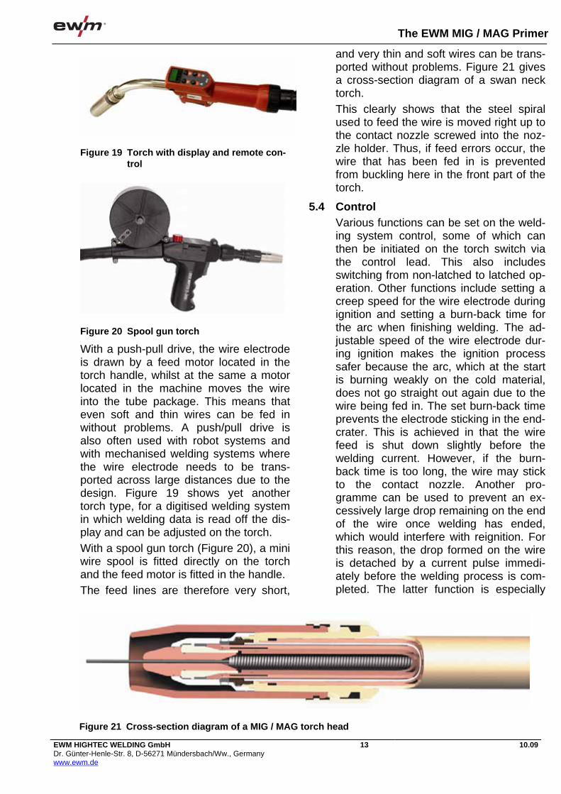
The EWM MIG / MAG Primer
EWM HIGHTEC WELDING GmbH Dr. Günter-Henle-Str. 8, D-56271 Mündersbach/Ww., Germany www.ewm.de
13 10.09
With a push-pull drive, the wire electrode is drawn by a feed motor located in the torch handle, whilst at the same a motor located in the machine moves the wire into the tube package. This means that even soft and thin wires can be fed in without problems. A push/pull drive is also often used with robot systems and with mechanised welding systems where the wire electrode needs to be trans-ported across large distances due to the design. Figure 19 shows yet another torch type, for a digitised welding system in which welding data is read off the dis-play and can be adjusted on the torch. With a spool gun torch (Figure 20), a mini wire spool is fitted directly on the torch and the feed motor is fitted in the handle. The feed lines are therefore very short,
and very thin and soft wires can be trans-ported without problems. Figure 21 gives a cross-section diagram of a swan neck torch. This clearly shows that the steel spiral used to feed the wire is moved right up to the contact nozzle screwed into the noz-zle holder. Thus, if feed errors occur, the wire that has been fed in is prevented from buckling here in the front part of the torch.
5.4 Control Various functions can be set on the weld-ing system control, some of which can then be initiated on the torch switch via the control lead. This also includes switching from non-latched to latched op-eration. Other functions include setting a creep speed for the wire electrode during ignition and setting a burn-back time for the arc when finishing welding. The ad-justable speed of the wire electrode dur-ing ignition makes the ignition process safer because the arc, which at the start is burning weakly on the cold material, does not go straight out again due to the wire being fed in. The set burn-back time prevents the electrode sticking in the end-crater. This is achieved in that the wire feed is shut down slightly before the welding current. However, if the burn-back time is too long, the wire may stick to the contact nozzle. Another pro-gramme can be used to prevent an ex-cessively large drop remaining on the end of the wire once welding has ended, which would interfere with reignition. For this reason, the drop formed on the wire is detached by a current pulse immedi-ately before the welding process is com-pleted. The latter function is especially
Figure 19 Torch with display and remote con-trol
Figure 20 Spool gun torch
Figure 21 Cross-section diagram of a MIG / MAG torch head
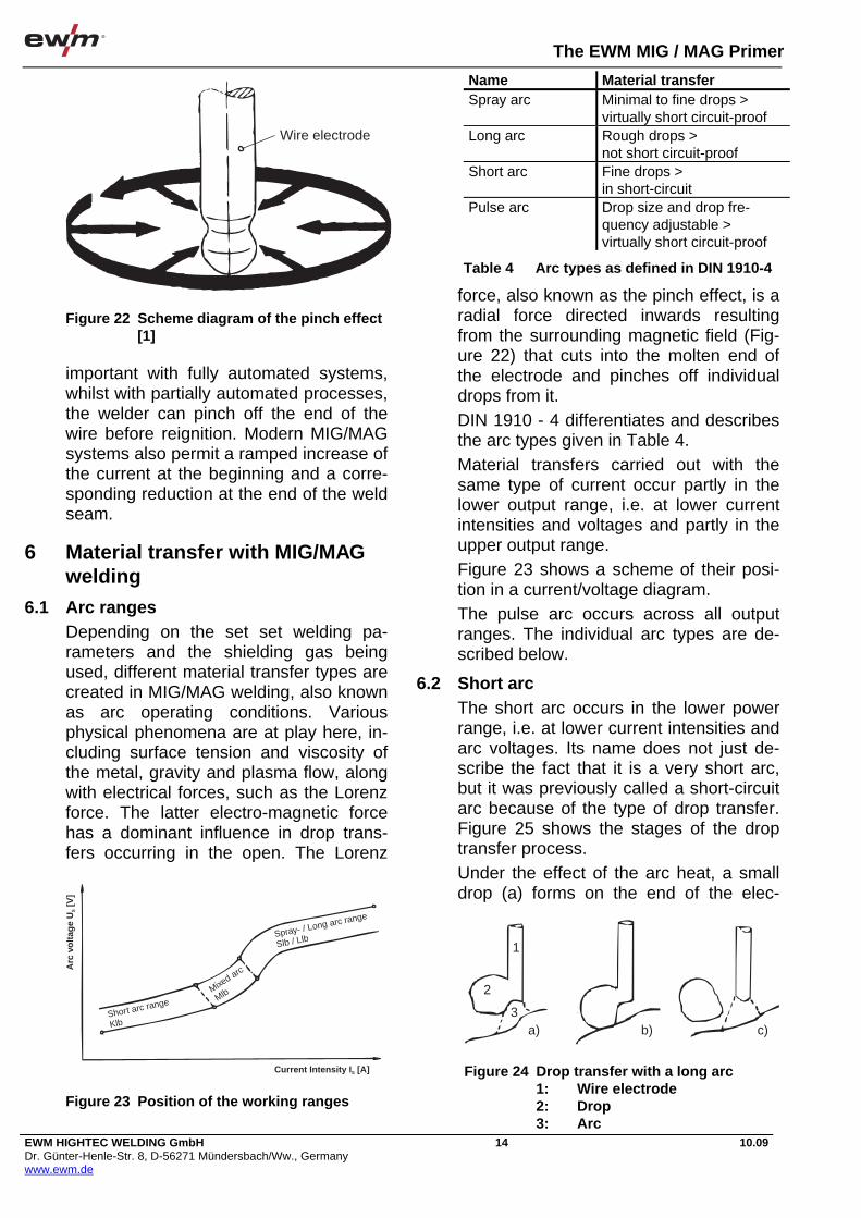
The EWM MIG / MAG Primer
EWM HIGHTEC WELDING GmbH Dr. Günter-Henle-Str. 8, D-56271 Mündersbach/Ww., Germany www.ewm.de
14 10.09
important with fully automated systems, whilst with partially automated processes, the welder can pinch off the end of the wire before reignition. Modern MIG/MAG systems also permit a ramped increase of the current at the beginning and a corre-sponding reduction at the end of the weld seam.
6 Material transfer with MIG/MAG welding
6.1 Arc ranges Depending on the set set welding pa-rameters and the shielding gas being used, different material transfer types are created in MIG/MAG welding, also known as arc operating conditions. Various physical phenomena are at play here, in-cluding surface tension and viscosity of the metal, gravity and plasma flow, along with electrical forces, such as the Lorenz force. The latter electro-magnetic force has a dominant influence in drop trans-fers occurring in the open. The Lorenz
force, also known as the pinch effect, is a radial force directed inwards resulting from the surrounding magnetic field (Fig-ure 22) that cuts into the molten end of the electrode and pinches off individual drops from it. DIN 1910 - 4 differentiates and describes the arc types given in Table 4. Material transfers carried out with the same type of current occur partly in the lower output range, i.e. at lower current intensities and voltages and partly in the upper output range. Figure 23 shows a scheme of their posi-tion in a current/voltage diagram. The pulse arc occurs across all output ranges. The individual arc types are de-scribed below.
6.2 Short arc The short arc occurs in the lower power range, i.e. at lower current intensities and arc voltages. Its name does not just de-scribe the fact that it is a very short arc, but it was previously called a short-circuit arc because of the type of drop transfer. Figure 25 shows the stages of the drop transfer process. Under the effect of the arc heat, a small drop (a) forms on the end of the elec-
Wire electrode
Figure 22 Scheme diagram of the pinch effect [1]
Name Material transfer Spray arc Minimal to fine drops >
virtually short circuit-proof Long arc Rough drops >
not short circuit-proof Short arc Fine drops >
in short-circuit Pulse arc Drop size and drop fre-
quency adjustable > virtually short circuit-proof
Table 4 Arc types as defined in DIN 1910-4
Current Intensity I [A]S
Short arc range
Klb
Mixed arc
Mlb
Spray- / Long arc range
Slb / Llb
Arc
vo
ltag
e U
[V]
S
Figure 23 Position of the working ranges
1
2
3a) b) c)
Figure 24 Drop transfer with a long arc 1: Wire electrode 2: Drop 3: Arc

The EWM MIG / MAG Primer
EWM HIGHTEC WELDING GmbH Dr. Günter-Henle-Str. 8, D-56271 Mündersbach/Ww., Germany www.ewm.de
15 10.09
trode, which due to the short arc comes rapidly into contact with the molten bath. A short-circuit is produced and the arc goes out (b). The drop is sucked away from the end of the wire by the surface tension of the molten bath; the pinch ef-fect has no significant impact on the drop detachment due to the low current inten-sity. The arc then re-ignites (c). This pro-cess is repeated at very regular intervals of approx. 20 to 100 times a second, de-pending on the shielding gas used. Dur-ing the short-circuit phase, the current increases (short-circuit current). Due to the small size of the drop, the short-circuit phase is very short, however, and there are no especially high current peaks. In addition, chokes in the welding current circuit slow down the rate at which the current is increased with conventional power sources. This makes the arc re-ignition after the short-circuit gentle and without any significant amount of spatter. With inverters, the software for the power source prevents an excessive rise in the current. Using a short arc is a relatively “cold” process. It occurs when using all shield-ing gases for welding root passes, thin panels and out-of-position welding.
6.3 Long arc The long arc occurs in the upper power range when welding with carbon dioxide or shielding gases with a high CO2 con-tent. The limit for the CO2 content in this case is around 25 %. As the arc base is greatly constricted at the wire electrode due to the physical properties of the arc
atmosphere using these shielding gases, there is no pinch effect or it is only barely noticeable. Figure 24 clarifies this type of material transfer. Large drops form on the tip of the elec-trode (a) that are transferred to the work-piece primarily under the influence of gravity. Short-circuit bridges are often created between the drops and the mol-ten pool during this process (b), in which filler material is transferred into the mol-ten pool. Isolated, very large drops may sometimes also be transferred over (c). In this case the short-circuits are virtually continuous due to the large drop size. This produces very high short-circuit flows resulting in significant spatter for-mations when re-igniting the arc. This process, which occurs in the upper current intensity and voltage ranges, pro-duces a large, hot molten bath. The proc-ess is therefore only suited to welding in the flat and horizontal vertical positions (Figure 26). Out-of-position welding is not possible.
6.4 Spray arc When using argon and mixed gases rich in argon, the arc at the start of the drop surrounds the entire end of the electrode so that the pinch effect can be optimally
1
23
a) b) c)
Figure 25 Drop transfer with a short arc 1: Wire electrode 2: Drop 3: Arc
PA
PB
PG
PF
PE
PD
PC
Figure 26 Welding positions as defined in ISO 6947

The EWM MIG / MAG Primer
EWM HIGHTEC WELDING GmbH Dr. Günter-Henle-Str. 8, D-56271 Mündersbach/Ww., Germany www.ewm.de
16 10.09
set with sufficient current intensity (Figure 27). The end of the wire is constricted (a) and individual drops are detached from the electrode (b). This creates a short-circuit-proof, low-spatter material transfer. The spray arc occurs in the upper power range with shielding gases rich in argon. This type of arc also forms a large, hot molten bath, so that the process is only suitable for out-of-position welding in a limited way.
6.5 Mixed arc In between the short arc on the one hand and the spray or long arc on the other is an arc shape for which a mixed material transfer is typical partly in the short-circuit and partly in free movement. In this area, however, significant spatter formation is created, even using mixed gases rich in argon. It is therefore advisable to avoid this moderate current intensity range or to use a pulse arc.
6.6 Pulse arc The pulse arc occurs if a pulse-shaped current is used for welding instead of a uniform current. The setting parameters with this type of arc, are depending on the modulation of the power source, the wire feed speed as well as the base cur-rent or the base voltage, the pulse current or pulse voltage, the pulse duration and the pulse frequency. As shown in Figure 28, a drop detaches from the electrode tip due to the pinch effect in the pulse phase.
This creates a fine-drop, low-spatter welding process. With fixed values for the base current (voltage), pulse current (voltage) and pulse duration, the deposition power can be set using the wire feed and the arc length adjusted by changing the pulse frequency. The pulse arc occurs across the entire power range and is also suit-able for out-of-position welding in the lower and moderate current intensity ranges.
6.7 Special types of material transfer In addition to the standard arc types al-ready described, other special types have been increasingly used over the past few years. With current intensities above those for the conventional spray arc, i.e. with wire feed rates of 1.2 mm wire, e.g. of more than 15 m/min, high deposition power spray arcs occur when using mixed gases. However, this creates such a deep, cutting fusion penetration that faults could occur in the weld metal. It is therefore seldom used. When increasing the voltage, the arc begins to rotate in this power range and the fusion penetra-tion expands. The rotating arc is used to increase the deposition power or to raise the welding speed for filler and final passes with butt welds and fillet welds on thick-walled components. With high deposition power short arcs, the process has a material transfer in the typical short-circuit transfer mode. It oc-curs at current intensities in the same range for the conventional spray arc, but
1
23
a) b)
Figure 27 Drop transferwith a spray arc 1: Wire electrode 2: Drop 3: Arc
Figure 28 Drop detachment with a pulse arc

The EWM MIG / MAG Primer
EWM HIGHTEC WELDING GmbH Dr. Günter-Henle-Str. 8, D-56271 Mündersbach/Ww., Germany www.ewm.de
17 10.09
at a considerably lower arc voltage. The high deposition power variants of MIG/MAG welding are only used with full automation, with a few exceptions.
7 Setting the set welding parame-ters
7.1 Setting with conventional systems In contrast to manual arc welding and TIG welding, two adjustments are re-quired to set up MIG/MAG systems. This process is described below using the ex-ample of setting a step switch machine. For MIG/MAG welding, constant voltage power sources are used. The required voltage is therefore selected by setting a specific characteristic on the rough and fine step switches for the power source and the most suitable arc is achieved by setting the relevant wire feed speed. Fig-ure 29 shows how changes in the power source setting and the wire feed speed affect the position of the working point. The working point (A) is the intersection between the source characteristic set and the arc characteristic. It is identified using the current intensity Is and the voltage Us. If the wire feed speed is increased, the arc shortens, the working point moves to the right on the source characteristic and the current intensity rises. The oppo-site occurs when the wire feed speed is reduced. This means that the potentiome-ter for the wire feed unit can be used to set the required current intensity. When the current intensity is increased, the arc
is shortened, however. The voltage must be increased irrespectively at the same time to ensure that the arc does not become too short. When increasing the volt-age, a higher characteristic needs to be set on the step switch, and when reducing the arc voltage, a lower characteristic is required. With the most common, slightly falling shape of the horizontal power source characteristic, adjusting the
required parameter will always also result in a slight change in the other parameter. With a completely horizontal form, the pa-rameters do not have a reciprocal effect. In order to provide optimum conditions for welding, the arc must not be too short or too long. If the arc is too short, increased short circuits and therefore spatter occur. The short circuits can be detected by the rattling noise produced by the arc. As the arc increases in length, there is an in-creased risk of air penetrating the arc area, producing a greater risk of pores. The tendency to form undercuts also in-creases. The welder can detect an arc that is too long, because the arc will emit a hissing noise. The line for the ideal working points, i.e. the ideal working characteristic, runs roughly diagonally through the current/voltage diagram. In reality there is one useable arc character-istic. This is the working range that should be used for welding. Figure 30
Arc is to long
Arc is to short = IUsable arccharacteristicsarea
A = Working point
Current I (A)
Val
tage
U (
V)
Sourcecharacteristics
Figure 29 Suitable arc ranges with MIG/MAG welding [1]
Wire electrode SG 2-1,2mm
Arc
vol
tage
Welding current
Ar + 18% CO2
Ar + 8% CO2
Figure 30 Working ranges for two argon mixed gases [1] Klb = Short arc Mlb = Mixed arc Slb = Spray arc Wire electrode SG2 = G3Si-EN 440

The EWM MIG / MAG Primer
EWM HIGHTEC WELDING GmbH Dr. Günter-Henle-Str. 8, D-56271 Mündersbach/Ww., Germany www.ewm.de
18 10.09
shows the working ranges for a Si/Mn al-loy wire electrode and two different mixed gases. All working points inside the working ranges represent good welding condi-tions. Working points falling downwards mean excessively short arcs, and working points above the upper limit line produce arcs that are too long. The working ranges only ever apply for a specific wire electrode. As changing the shielding gas results in different physical conditions in the arc atmosphere, the working range also only ever applies to a specific shield-ing gas. When welding with pulse-shaped current, the pulse arc occurs across the entire range. However, as the material transition is short circuit-proof in any case, the range limits at lower and moderate cur-rent intensities tend to create higher arc voltages.
7.2 Synergetic setting of set welding pa-rameters As there are not always sufficient num-bers of sufficiently well trained welders available in all sectors, modern MIG/MAG systems offer simplified options for set-ting the set welding parameters, such as the PHOENIX multiprocess machine (Figure 31).
It began as early as the 1970s with one-dial operation where a single rotary po-tentiometer was used to set the deposi-tion power by changing the wire feed, and the same adjusting knob in a specific transmission ratio was connected to an infinitely adjustable characteristic modify-ing device so that the voltage was modi-fied at the same time. A second knob also permitted specific corrections to be made to the working point. Today, many MIG/MAG systems provide a more far-reaching simplification of the setting work as standard. The ideal work-ing characteristics for commonly used welding tasks are saved in the machine. All the person operating the system needs to do is to use touch controls, for example, to set the material being welded, the required wire diameter and the shielding gas connected. This will call up the pre-programmed, optimum work-ing characteristic. The output can then be infinitely adjusted using a rotary dial, and a correction knob is available for specific requirements relating to the optimum arc. Figure 32 and Figure 33 show displays from modern welding systems that allow even more complex settings to be made. In the central section, the welding task can be set using touch controls. In addi-tion to prescribing the material and the wire electrode diameter, as well as the shielding gas, the control can be used to stipulate whether solid wire or cored wire should be used, or whether special tasks such as MIG brazing or GMA surfacing are to be performed. As the system is a multi-process system, this section is also used to change the characteristics re-quired for other processes (TIG, MMA). In
Figure 31 PHOENIX multi-process machines
Figure 32 Display on the PHOENIX 300 EX-PERT welding machine
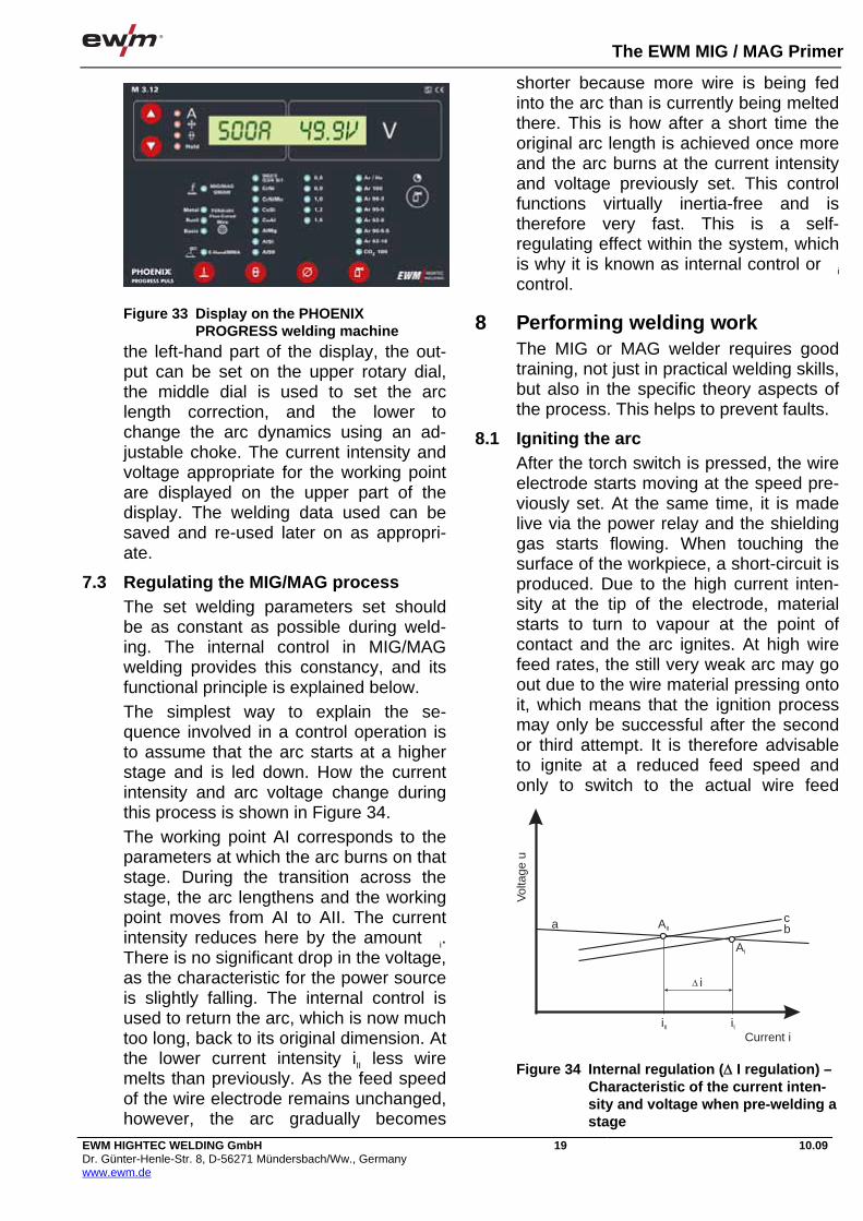
The EWM MIG / MAG Primer
EWM HIGHTEC WELDING GmbH Dr. Günter-Henle-Str. 8, D-56271 Mündersbach/Ww., Germany www.ewm.de
19 10.09
the left-hand part of the display, the out-put can be set on the upper rotary dial, the middle dial is used to set the arc length correction, and the lower to change the arc dynamics using an ad-justable choke. The current intensity and voltage appropriate for the working point are displayed on the upper part of the display. The welding data used can be saved and re-used later on as appropri-ate.
7.3 Regulating the MIG/MAG process The set welding parameters set should be as constant as possible during weld-ing. The internal control in MIG/MAG welding provides this constancy, and its functional principle is explained below. The simplest way to explain the se-quence involved in a control operation is to assume that the arc starts at a higher stage and is led down. How the current intensity and arc voltage change during this process is shown in Figure 34. The working point AI corresponds to the parameters at which the arc burns on that stage. During the transition across the stage, the arc lengthens and the working point moves from AI to AII. The current intensity reduces here by the amount @i. There is no significant drop in the voltage, as the characteristic for the power source is slightly falling. The internal control is used to return the arc, which is now much too long, back to its original dimension. At the lower current intensity iII less wire melts than previously. As the feed speed of the wire electrode remains unchanged, however, the arc gradually becomes
shorter because more wire is being fed into the arc than is currently being melted there. This is how after a short time the original arc length is achieved once more and the arc burns at the current intensity and voltage previously set. This control functions virtually inertia-free and is therefore very fast. This is a self-regulating effect within the system, which is why it is known as internal control or @i control.
8 Performing welding work The MIG or MAG welder requires good training, not just in practical welding skills, but also in the specific theory aspects of the process. This helps to prevent faults.
8.1 Igniting the arc After the torch switch is pressed, the wire electrode starts moving at the speed pre-viously set. At the same time, it is made live via the power relay and the shielding gas starts flowing. When touching the surface of the workpiece, a short-circuit is produced. Due to the high current inten-sity at the tip of the electrode, material starts to turn to vapour at the point of contact and the arc ignites. At high wire feed rates, the still very weak arc may go out due to the wire material pressing onto it, which means that the ignition process may only be successful after the second or third attempt. It is therefore advisable to ignite at a reduced feed speed and only to switch to the actual wire feed
Figure 33 Display on the PHOENIX PROGRESS welding machine
Vol
tage
u
Current iiII
AIIa cb
AI
i
iI
�
Figure 34 Internal regulation ( I regulation) – Characteristic of the current inten-sity and voltage when pre-welding a stage

The EWM MIG / MAG Primer
EWM HIGHTEC WELDING GmbH Dr. Günter-Henle-Str. 8, D-56271 Mündersbach/Ww., Germany www.ewm.de
20 10.09
speed once the arc is burning steadily. Newer types of MIG/MAG systems pro-vide the option of setting what is known as a “creep speed”. Ignition should never be performed outside the groove and only at points that are melted once more im-mediately afterwards. Crack formation can be assumed with ignition points which have not been pre-welded due to the high cooling speed of these points of localised heating.
8.2 Moving the torch The torch is tilted in the direction of weld-ing by around 10 ° to 20 ° and can be moved backhand or forehand (Figure 35). Its distance to the workpiece should be such that the free wire end, i.e. the dis-tance between the lower edge of the con-tact nozzle and the start point for the arc, is around 10 - 12 times the wire diameter [mm]. If the torch is tilted too much, there is a risk that air is sucked into the shield-ing gas. Forehand torch movements are normally used when welding solid wires, and backhand welding is used with cored wire that conveys slag. The torch is nor-mally moved with a slightly backhand mo-tion in the vertical down position. Vertical down welding (pos. PG) is used mainly with thinner panels. With thicker panels there is a risk of fusion faults due to weld metal running ahead. This type of fusion fault may also occur in other positions if welding is performed at too low a welding speed. Wide weaving movements should therefore be avoided wherever possible, except in the vertical up position. The standard weaving movement shape is the open triangle.
8.3 Ending the welding process At the end of the seam, the arc must not shut down suddenly or the torch removed from the end-crater. Especially with thicker panels where deep end-craters may occur in large-volume beads, it is advisable to remove the arc slowly from the bath or, if the system being used permits it, to set an end-crater filling pro-gram. With most systems, a specific post-flow time for the shielding gas can also be set, so that the last molten weld metal remaining can embrittle under the shield-ing gas shroud. However, this is only effective if the torch is held at the end of the seam for a time.
8.4 Welding parameters The lower limit for the possible use of the process for butt welds with unalloyed steel is around 0.7 mm, with stainless steel 1 mm and with aluminium materials around 2 mm. Root passes and thin panels are gener-ally welded using a short arc or using a lower power range pulse arc. With filler, final and backing runs on thicker panels, spray or long arcs are set with higher power range. These welding tasks can also be performed with very low spatter with the pulse arc. Guidelines for suitable welding data for welding butt welds and fillet welds are given in Table 5 to Table 9.
< 20°
Figure 35 Position of the torch against the parent metal
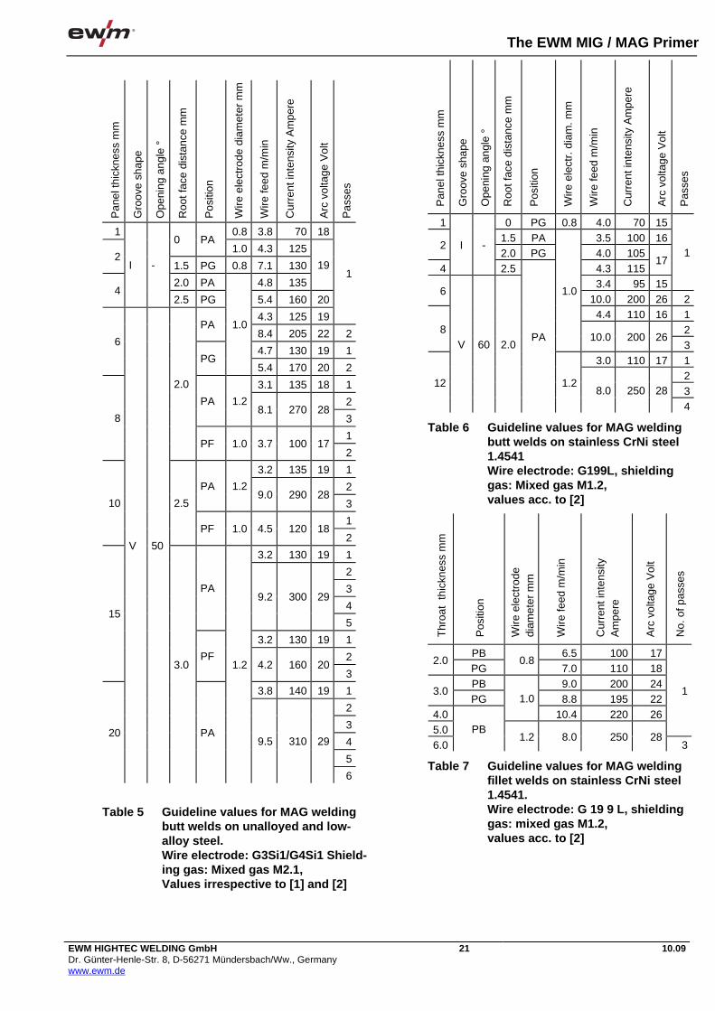
The EWM MIG / MAG Primer
EWM HIGHTEC WELDING GmbH Dr. Günter-Henle-Str. 8, D-56271 Mündersbach/Ww., Germany www.ewm.de
21 10.09
Pan
el th
ickn
ess
mm
Gro
ove
shap
e
Ope
ning
ang
le °
Roo
t fac
e di
stan
ce m
m
Pos
ition
Wire
ele
ctro
de d
iam
eter
mm
Wire
feed
m/m
in
Cur
rent
inte
nsity
Am
pere
Arc
vol
tage
Vol
t
Pas
ses
1 0.8 3.8 70 180 PA
1.0 4.3 1252
1.5 PG 0.8 7.1 130
2.0 PA 4.8 135
19
4
I -
2.5 PG 5.4 160 20
4.3 125 19
1
PA 8.4 205 22 2
4.7 130 19 16
PG
1.0
5.4 170 20 2
3.1 135 18 1
2PA 1.2 8.1 270 28
3
1
8
2.0
PF 1.0 3.7 100 172
3.2 135 19 1
2PA 1.2 9.0 290 28
3
1
10 2.5
PF 1.0 4.5 120 182
3.2 130 19 1
2
3
4
PA 9.2 300 29
5
3.2 130 19 1
2
15
PF 4.2 160 20
3
3.8 140 19 1
2
3
4
5
20
V 50
3.0
PA
1.2
9.5 310 29
6
Table 5 Guideline values for MAG welding butt welds on unalloyed and low-alloy steel. Wire electrode: G3Si1/G4Si1 Shield-ing gas: Mixed gas M2.1, Values irrespective to [1] and [2]
Pan
el th
ickn
ess
mm
Gro
ove
shap
e
Ope
ning
ang
le °
Roo
t fac
e di
stan
ce m
m
Pos
ition
Wire
ele
ctr.
dia
m. m
m
Wire
feed
m/m
in
Cur
rent
inte
nsity
Am
pere
Arc
vol
tage
Vol
t
Pas
ses
1 0 PG 0.8 4.0 70 151.5 PA 3.5 100 16
22.0 PG 4.0 105
4
I -
2.5 4.3 11517
3.4 95 15
1
610.0 200 26 24.4 110 16 1
28
1.0
10.0 200 263
3.0 110 17 123
12
V 60 2.0 PA
1.2 8.0 250 28
4
Table 6 Guideline values for MAG welding butt welds on stainless CrNi steel 1.4541 Wire electrode: G199L, shielding gas: Mixed gas M1.2, values acc. to [2]
Thr
oat
thic
knes
s m
m
Pos
ition
Wire
ele
ctro
de
diam
eter
mm
Wire
feed
m/m
in
Cur
rent
inte
nsity
A
mpe
re
Arc
vol
tage
Vol
t
No.
of p
asse
s
PB 6.5 100 172.0
PG 0.8
7.0 110 18PB 9.0 200 24
3.0PG 8.8 195 22
4.0
1.0
10.4 220 265.0
1
6.0
PB 1.2 8.0 250 28
3
Table 7 Guideline values for MAG welding fillet welds on stainless CrNi steel 1.4541. Wire electrode: G 19 9 L, shielding gas: mixed gas M1.2, values acc. to [2]

The EWM MIG / MAG Primer
EWM HIGHTEC WELDING GmbH Dr. Günter-Henle-Str. 8, D-56271 Mündersbach/Ww., Germany www.ewm.de
22 10.09
Pan
el th
ickn
ess
mm
Gro
ove
shap
e
Ope
ning
ang
le °
Roo
t fac
e th
ickn
ess
mm
Wire
ele
ctro
de d
i-am
eter
mm
Wire
feed
m/m
in
Cur
rent
inte
nsity
A
mpe
re
Arc
vol
tage
Vol
t
Pas
ses
2 2 0.8 5.0 110 204
I - 4 1.2 3.1
6 6.0 170 22
1
8 70 1.5
6.8 220 26.2 200
261
6.0 170 24 210 2.0 1.6
7.2 230 G13.7 240 112.2 220
26
212
Y 60
1.5 1.2
15.6 250 28 G*) without root face surface spacing G= backing run
Table 8 Guideline values for MIG welding butt welds on aluminium materials Wire electrode: GRAlMg5, shielding gas: argon, flat welding position, values acc. to [1] and [2]
Effe
ctiv
e th
roat
thic
k-ne
ss/m
m
Pos
ition
Wire
ele
ctro
de d
iam
eter
m
m
Wire
feed
m/m
in
Cur
rent
inte
n-si
ty/a
mpe
res
Arc
vol
tage
Vol
t
Pos
ition
no.
PA/PB 1.0
PG 3.8 65 17
PA/PB 7.3 130 19 2.0
PG
0.8
7.1 100 20 PB 10.6 215 23
3.0 PG 9.0 210 22
4.0 PA/PB
1.0
10.7 220 23 5.0
PB 1.2 9.5 300 29 6.0
PF 1.0 4.7 115 18
1
PB 1.2 9.5 300 29 38.0
PF 1.0 4.8 130 19 2PB 9.5 300 29 3
10.0 PF
1.2 4.2 165 19 2
Table 9 Guideline values for MAG welding fillet welds on unalloyed and low-alloy steel. Wire electrode: G3Si1/G4Si1, Shielding gas: mixed gas M2.1, Values acc. to [1]
The current and voltage values used for information purposes by the welder are displayed on the measuring devices, which are normally integrated into the
machines. With pulse welding, the display instruments show the arithmetic average value of the current intensity and arc volt-age produced in the pulse and base phase at the set pulse frequency. The ta-bles can therefore also be used as guide-line values for MIG/MAG pulse welding. If no measuring devices are integrated into the machine, external devices can be used for measuring, or the welder needs to refer to the wire feed speed also given in the tables. The correct arc length then needs to be set irrespective to what the welder sees and hears.
8.5 Automation options With partly mechanised MIG/MAG weld-ing, the addition of the filler material and the shielding gas, and the arc length con-trol are automated, and only the welding movement itself needs to be performed manually. A simple option for full mechanisation is to clamp the torch and move it over the workpiece at welding speed using a trol-ley or by affixing the torch in a stationary position and moving a rotationally sym-metrical component underneath the torch in a rotating device (Figure 36).
Figure 36 Fully automated welding

The EWM MIG / MAG Primer
EWM HIGHTEC WELDING GmbH Dr. Günter-Henle-Str. 8, D-56271 Mündersbach/Ww., Germany www.ewm.de
23 10.09
The functional principle of the process also makes this procedure suitable for dif-ficult mechanisation tasks where, for ex-ample, multiple torches are used simultaneously on one workpiece. Not without reason is MIG/MAG welding therefore also by far the most commonly used process with industrial robots for arc welding.
9 Work safety In MIG/MAG welding the arc transfers the drop. As a consequence of the high tem-peratures prevailing there, there is more metal vapour than with the TIG process, for example. More harmful gases and smoke are therefore produced. With cored electrodes, this amount increases due to the filler components being vapor-ised. It is therefore a requirement that ex-traction is virtually always used directly at the point of origin, both with extended pe-riods of welding work performed at a fixed position and with short-term usage. With non-localised welding work, fresh air is sufficient, or mechanised ventilation of the room is sufficient, except for welding high-alloy steels and coated materials. An extractor can be integrated into the torch in MIG/MAG welding (Figure 37). It is important that the extraction nozzle is designed so that the shielding gas is not also sucked away from the welding point. The welder must also protect himself against radiation from the arc and against electrical dangers. To protect against the infrared and ultraviolet radiation, the
MIG/MAG welder normally wears a hel-met, which leaves both hands free. The filter glass is integrated into this safety helmet. This filter has recently been de-fined in DIN EN 169. There are various grades of protection that need to be per-manently affixed to the glass. With MIG/MAG welding, filters of protection grades 10 to 15 are used, depending on the current intensity, where grade 10 is prescribed for lower currents and 15 for the higher current intensities. The greatest electrical risk is represented by the open circuit voltage. This is the maximum voltage present on the acti-vated power source between the connec-tion sockets when the arc is not burning. After the arc is ignited, the voltage is much lower; in MIG/MAG welding only around 17 to 30 volts. Irrespective to the relevant German accident prevention regulations, power sources for direct cur-rent in normal operation should have an open circuit voltage peak value of max. 113 volts. With alternating current sys-tems, which in recent times have been used in special cases with MIG/MAG welding, this value is also 113 Volts, but the peak value is limited to max. 80 Volts. Where there is an increased risk of elec-tric shock, e.g. when welding in small spaces or on large iron masses, reduced values apply for alternating current, e.g. a peak value of 68 volts and an r.m.s. value of 48 volts. Modern welding power sources meeting these requirements bear the “S” safety sign in conformance with DIN EN 60974-1. Older power sources may still be marked with “K” (d.c.) or “42 V” (a.c.). The safest way for welders to protect themselves against electric shocks is to wear undamaged welding gloves made from leather and well-insulated work clothes including safety shoes.
Torch angle
Extraction chamber
Vacuum zone
Vacuum zone
Air
Harmful substance Shielding gas MIG/MAG torch
Figure 37 Extraction integrated into the torch

The EWM MIG / MAG Primer
EWM HIGHTEC WELDING GmbH Dr. Günter-Henle-Str. 8, D-56271 Mündersbach/Ww., Germany www.ewm.de
24 10.09
10 Special features of different ma-terials As mentioned above, the MIG/MAG pro-cess is suitable for welding a large range of materials. The sections below cover various special features of the different materials.
10.1 Un-alloyed and low-alloy steels Unalloyed and low-alloy steels are welded using mixed gases M1, M2, M3 or using pure carbon dioxide (Figure 38). Due to the low spatter formation, primarily in the upper power range, mixed gases predominate in Germany, however. These steels can normally be welded very well using the MAG process. One exception is grades with a high carbon content, such as E 360 (formerly St. 70), with approx. 0.45 % C. Due to the high fusion penetration of the process, the weld metal absorbs a relatively larger amount of carbon via dilution, creating a higher risk of hot cracks. This can be remedied by all measures that reduce the fusion penetration and therefore also the dilution. This includes low current intensi-ties and welding on forward traveling weld metals - Caution: Risk of fusion faults. Pores form in unalloyed and low-alloy steels primarily due to nitrogen. This can be due to dilution when welding steels
with a high nitrogen content, e.g. nitriding steels. However, the nitrogen is normally absorbed from the air due to an incom-plete shielding gas bell. Safe protection from this is guaranteed if the correct quantity of shielding gas has been set and turbulence in the shielding gas flow, e.g. due to spatter in the shielding gas nozzle or instabilities in the process, is avoided. Carbon dioxide as a shielding gas is less sensitive to this type of pore formation than mixed gases. With mixed gases, the sensitivity is reduced as the CO2 content increases.
10.2 High-alloy steels and nickel-based al-loys This group of materials can in principle also be welded well using the MIG/MAG process. The shielding gases used for high-alloy steels are argon/oxygen mix-tures with 1-5 % oxygen (M1.1) or argon with CO2 contents of up to 2.5% (M1.2). A significant disadvantage when welding corrosion-resistant steels is the oxide skins which occur after welding and which are left on and next to the seam. These skins need to be removed by brushing, etching or blasting before the component is used in operation, because they impair the corrosion-resistance of the metal. The amount of cleaning work required for MAG-welded seams is greater than with MMA welding, where the slag covering prevents oxygen from penetrating the seam surface at higher temperatures. Part of the economic ad-vantages of part-mechanised welding can therefore be lost due to the amount of clean-up work required. Mixed gases containing CO2 are more favourable in this respect than those containing O2. They are therefore being increasingly used. The carbon dioxide content in shielding gas must not be too high, how-ever, as the gas decomposing in the arc causes the weld metal to carbonise, which in turn reduces the corrosion-resistance. The permissible CO2 content is therefore limited to max. 5 %. When welding corrosion-resistant steels, any overheating must be avoided be-
Figure 38 MAG welding on beams in steel construction work
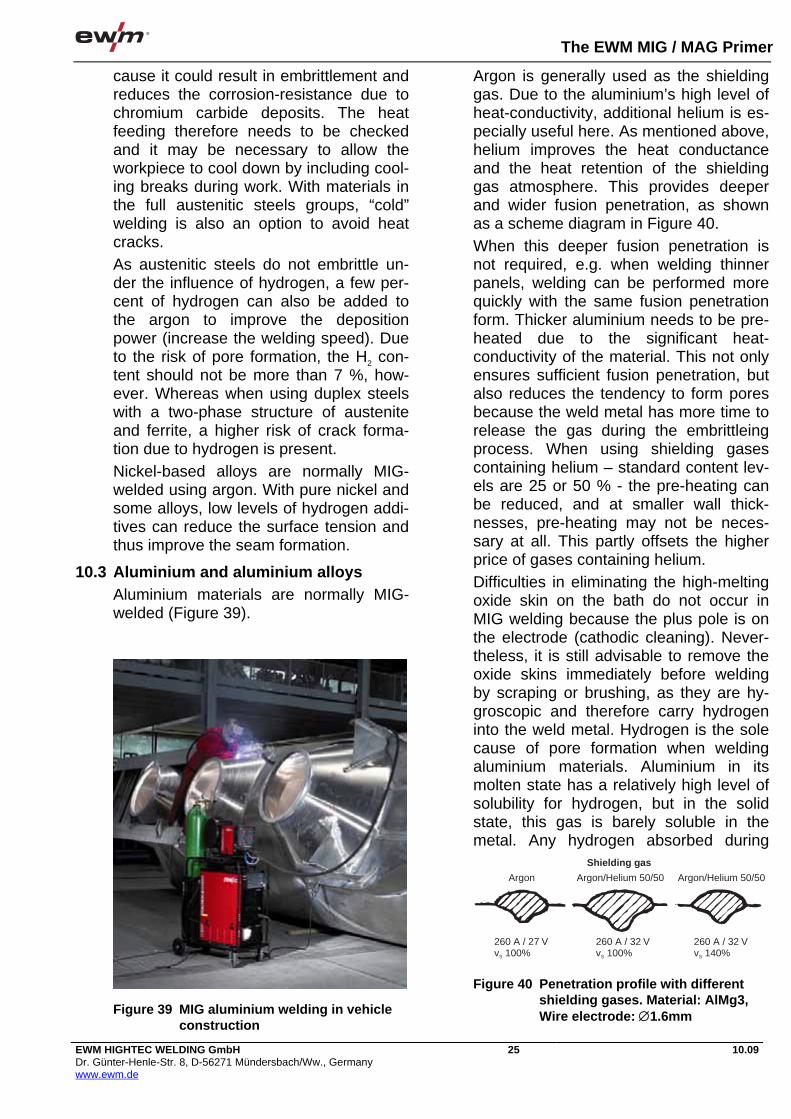
The EWM MIG / MAG Primer
EWM HIGHTEC WELDING GmbH Dr. Günter-Henle-Str. 8, D-56271 Mündersbach/Ww., Germany www.ewm.de
25 10.09
cause it could result in embrittlement and reduces the corrosion-resistance due to chromium carbide deposits. The heat feeding therefore needs to be checked and it may be necessary to allow the workpiece to cool down by including cool-ing breaks during work. With materials in the full austenitic steels groups, “cold” welding is also an option to avoid heat cracks. As austenitic steels do not embrittle un-der the influence of hydrogen, a few per-cent of hydrogen can also be added to the argon to improve the deposition power (increase the welding speed). Due to the risk of pore formation, the H2 con-tent should not be more than 7 %, how-ever. Whereas when using duplex steels with a two-phase structure of austenite and ferrite, a higher risk of crack forma-tion due to hydrogen is present. Nickel-based alloys are normally MIG-welded using argon. With pure nickel and some alloys, low levels of hydrogen addi-tives can reduce the surface tension and thus improve the seam formation.
10.3 Aluminium and aluminium alloys Aluminium materials are normally MIG-welded (Figure 39).
Argon is generally used as the shielding gas. Due to the aluminium’s high level of heat-conductivity, additional helium is es-pecially useful here. As mentioned above, helium improves the heat conductance and the heat retention of the shielding gas atmosphere. This provides deeper and wider fusion penetration, as shown as a scheme diagram in Figure 40. When this deeper fusion penetration is not required, e.g. when welding thinner panels, welding can be performed more quickly with the same fusion penetration form. Thicker aluminium needs to be pre-heated due to the significant heat-conductivity of the material. This not only ensures sufficient fusion penetration, but also reduces the tendency to form pores because the weld metal has more time to release the gas during the embrittleing process. When using shielding gases containing helium – standard content lev-els are 25 or 50 % - the pre-heating can be reduced, and at smaller wall thick-nesses, pre-heating may not be neces-sary at all. This partly offsets the higher price of gases containing helium. Difficulties in eliminating the high-melting oxide skin on the bath do not occur in MIG welding because the plus pole is on the electrode (cathodic cleaning). Never-theless, it is still advisable to remove the oxide skins immediately before welding by scraping or brushing, as they are hy-groscopic and therefore carry hydrogen into the weld metal. Hydrogen is the sole cause of pore formation when welding aluminium materials. Aluminium in its molten state has a relatively high level of solubility for hydrogen, but in the solid state, this gas is barely soluble in the metal. Any hydrogen absorbed during
Figure 39 MIG aluminium welding in vehicle construction
Shielding gas
Argon Argon/Helium 50/50 Argon/Helium 50/50
260 A / 27 Vv 100%S
260 A / 32 Vv 100%S
260 A / 32 Vv 140%S
Figure 40 Penetration profile with different shielding gases. Material: AlMg3, Wire electrode: 1.6mm

The EWM MIG / MAG Primer
EWM HIGHTEC WELDING GmbH Dr. Günter-Henle-Str. 8, D-56271 Mündersbach/Ww., Germany www.ewm.de
26 10.09
welding must therefore exit the weld metal before embrittleing if no pores are to be formed. This is not always possible, especially with thicker sizes. Completely pore-free seams cannot be achieved with aluminium materials for larger wall thick-nesses. The favourable effect of pre-heating has already been mentioned. AlMg and AlSi alloys tend towards heat cracks during welding at Si contents of around 1% or Mg contents of around 2%. This alloy range should be avoided when choosing the filler material. Wire elec-trodes with an alloy content one degree higher are therefore better than elec-trodes of exactly the same type.
10.4 Other materials In addition to the materials already men-tioned, only copper and copper alloys are MIG-welded in any significant quantity. Pure copper needs a relatively high level of pre-heating in order to avoid fusion faults due to its high heat conductivity. The weld metal for bronze wires, e.g. made from aluminium bronze or tin bronze, has good sliding properties. It is therefore used for GMA-surfacing sliding surfaces. With welds of this type on iron materials, the fusion penetration needs to be kept low using relevant measures, be-cause iron has a low level of solubility in copper. It is included in the weld metal in the form of small balls and reduces the usage properties. The conditions for MIG brazing are simi-lar. This process is used to connect zinc-plated panels in automobile construction, for example. The fillers used are wire electrodes made from silicon bronze or tin bronze. Due to the low melting point of these bronzes, the zinc vaporisation level is reduced. Fewer pores are produced and the protection provided by the zinc coating is retained right up to near the seam and on the back of the panels. In this situation, too, no fusion penetration should occur in the steel material if pos-sible, but the connection should be made solely via diffusion and adhesion forces, as in brazing. This is achieved by using modified set welding parameters and a
special torch position, such that the arc burns only on the molten bath.
11 Applications for MIG / MAG weld-ing
11.1 Uses in manufacturing Irrespective to recent statistics, the pro-portion of MIG/MAG welding used on de-posited weld metal in relation to all arc welding processes is 80%. There are virtually no branches of indus-try where MIG/MAG welding is not used. The main areas of usage are in vehicle construction, where heavy goods vehi-cles, locomotives and ships are manufac-tured, for example. Aluminium is increasingly being used as the material for these applications. Other uses are to be found in steel and bridge construction work, and in the construction of ships and machines. In crane and excavator con-struction, higher strength steels are in-creasingly being used, something for which MAG welding is particularly appro-priate because the weld metal has a lower hydrogen content, allowing no cold cracks to occur. MAG welding is slightly under-represented in boiler, equipment and pipeline construction where, due to the excellent quality of the weld metal, basic stick electrodes are often still used for welding. MAG welding is not just used for indus-trial applications, however, but also in the trades it is hard to find a workshop that does not use the process. This applies both to car bodyshops and to metalwork-ing firms and small steel construction op-erations.
11.2 Example applications In conclusion, a few selected example applications are used here to clarify the proper use of MIG/MAG process. Figure 38 shows the use of MAG welding in steel construction work. On beams such as those shown in the il-lustration, fillet welds or double bevel butt welds are used on the corners. With longer beams, butt welds also need to be used crosswise to the main load direc-

The EWM MIG / MAG Primer
EWM HIGHTEC WELDING GmbH Dr. Günter-Henle-Str. 8, D-56271 Mündersbach/Ww., Germany www.ewm.de
27 10.09
tion. Particular specifications apply to these welds with regard to preventing faults. On car bodies, short MAG seams are used in addition to numerous resistance welding points (Figure 41). Galvanised panels are also MIG brazed. Bodywork made from aluminium is resis-tance spot and MIG welded. Figure 42 shows MIG welding on tanks for tanker vehicles, manufactured from aluminium alloys. A push/pull unit is used here for welding so that there are no feed problems with the relatively soft aluminium wires.
12 Literature [1] R. Killing: Handbuch der Schweißver-fahren, Teil 1: Lichtbogenschweißen, Fachbuchreihe Schweißtechnik, Band 76/I, DVS-Verlag Düsseldorf 1999 [2] G. Aichele: Leistungskennwerte für Schweißen und Schneiden, Fachbuchrei-he Schweißtechnik, Band 72, DVS Verlag Düsseldorf 1994
13 Imprint The MIG/MAG Primer, 3rd edition 2009 From the EWM Knowledge range of pub-lications – All about welding All rights reserved. Reprinting, including extracts, is forbid-den. No part of this brochure may be re-produced or electronically processed, reproduced or distributed in any form (photocopy, microfilm or any other proce-dure) without the written permission of EWM. © EWM HIGHTEC WELDING GmbH Dr.-Günter-Henle-Str. 8 D-56271 Mündersbach, Germany Phone: +49(0)2680.181-0 Fax: +49(0)2680.181-244 mailto:[email protected] http://www.ewm.de
Figure 41 MIG brazing in assembly vehicle bodywork
Figure 42 MIG welding used to manufacture tanks


PLASMA PRIMER


The EWM PLASMA Primer
EWM HIGHTEC WELDING GmbHDr.-Günter-Henle-Strasse 8 · D-56271 MündersbachPhone +49(0)2680.181-0 · Fax +49(0)2680.181-244www.ewm.de · [email protected]
10.09EWM HIGHTEC WELDING GmbHDr.-Günter-Henle-Strasse 8 · D-56271 MündersbachPhone +49(0)2680.181-0 · Fax +49(0)2680.181-244www.ewm.de · [email protected]
10.09
The EWM PLASMA Primer
1
Contents
1 Welding with a plasma arc.......................................................................................................................2
1.1 Introduction....................................................................................................................................2
2 The process.............................................................................................................................................2
2.1 General..........................................................................................................................................2
2.2 Current type...................................................................................................................................3
2.3 Electrodes .....................................................................................................................................3
2.4 Gases for plasma welding .............................................................................................................3
2.5 Filler metals ...................................................................................................................................4
3 Classification of plasma welding..............................................................................................................4
3.1 Plasma joint welding......................................................................................................................43.1.1 Micro plasma welding........................................................................................................43.1.2 Soft plasma welding ..........................................................................................................43.1.3 Thick sheet plasma welding ..............................................................................................53.1.4 Plasma powder joint welding.............................................................................................5
3.2 Plasma deposit welding.................................................................................................................6
3.3 Plasma brazing..............................................................................................................................6
4 Setups for plasma welding.......................................................................................................................7
4.1 Control ...........................................................................................................................................7
4.2 Power source.................................................................................................................................7
4.3 Welding torch.................................................................................................................................9
5 Performing the welding operation ............................................................................................................9
5.1 Setting the shielding gas quantity..................................................................................................9
5.2 Edge preparation.........................................................................................................................10
5.3 Forming .......................................................................................................................................10
5.4 Igniting the arc.............................................................................................................................10
5.5 Guiding the torch .........................................................................................................................11
5.6 Magnetic arc blow effect ..............................................................................................................11
5.7 Welding positions ........................................................................................................................11
5.8 Ending the welding operation ......................................................................................................11
5.9 Welding parameters ....................................................................................................................11
5.10 Work safety..................................................................................................................................12
5.11 Special features of different materials .........................................................................................125.11.1 Unalloyed and low-alloy steels ........................................................................................125.11.2 High-alloy steels ..............................................................................................................125.11.3 Aluminium and aluminium alloys .....................................................................................135.11.4 Other materials................................................................................................................155.11.5 Materials for plasma deposit welding ..............................................................................15
6 Applications for plasma welding and brazing.........................................................................................15
6.1 Example applications ..................................................................................................................15
6.2 Comparison with TIG welding......................................................................................................16
7 Literature ...............................................................................................................................................16
8 Imprint....................................................................................................................................................16
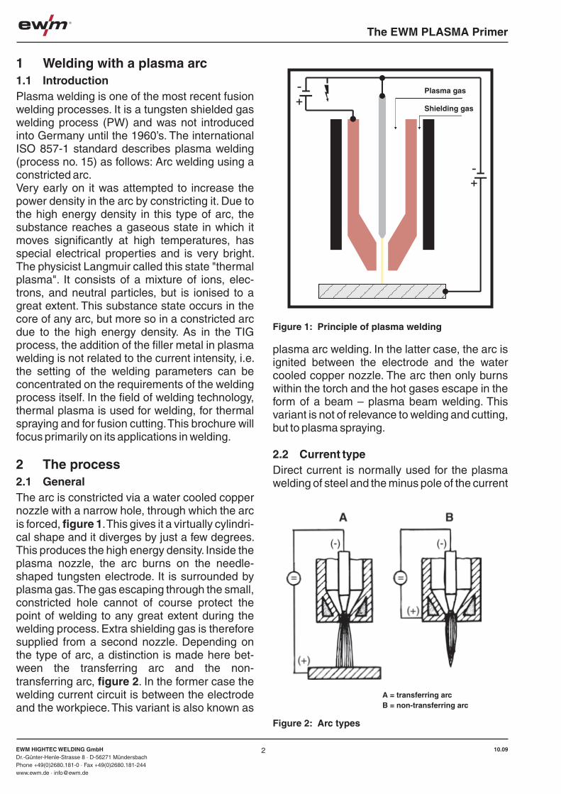
The EWM PLASMA Primer
EWM HIGHTEC WELDING GmbHDr.-Günter-Henle-Strasse 8 · D-56271 MündersbachPhone +49(0)2680.181-0 · Fax +49(0)2680.181-244www.ewm.de · [email protected]
10.09EWM HIGHTEC WELDING GmbHDr.-Günter-Henle-Strasse 8 · D-56271 MündersbachPhone +49(0)2680.181-0 · Fax +49(0)2680.181-244www.ewm.de · [email protected]
10.09
The EWM PLASMA Primer
1 Welding with a plasma arc1.1 IntroductionPlasma welding is one of the most recent fusion welding processes. It is a tungsten shielded gas welding process (PW) and was not introduced into Germany until the 1960’s. The international ISO 857-1 standard describes plasma welding (process no. 15) as follows: Arc welding using a constricted arc. Very early on it was attempted to increase the power density in the arc by constricting it. Due to the high energy density in this type of arc, the substance reaches a gaseous state in which it moves significantly at high temperatures, has special electrical properties and is very bright. The physicist Langmuir called this state "thermal plasma". It consists of a mixture of ions, elec-trons, and neutral particles, but is ionised to a great extent. This substance state occurs in the core of any arc, but more so in a constricted arc due to the high energy density. As in the TIG process, the addition of the filler metal in plasma welding is not related to the current intensity, i.e. the setting of the welding parameters can be concentrated on the requirements of the welding process itself. In the field of welding technology, thermal plasma is used for welding, for thermal spraying and for fusion cutting. This brochure will focus primarily on its applications in welding.
2 The process2.1 GeneralThe arc is constricted via a water cooled copper nozzle with a narrow hole, through which the arc is forced, figure 1. This gives it a virtually cylindri-cal shape and it diverges by just a few degrees. This produces the high energy density. Inside the plasma nozzle, the arc burns on the needle-shaped tungsten electrode. It is surrounded by plasma gas. The gas escaping through the small, constricted hole cannot of course protect the point of welding to any great extent during the welding process. Extra shielding gas is therefore supplied from a second nozzle. Depending on the type of arc, a distinction is made here bet-ween the transferring arc and the non-transferring arc, figure 2. In the former case the welding current circuit is between the electrode and the workpiece. This variant is also known as
plasma arc welding. In the latter case, the arc is ignited between the electrode and the water cooled copper nozzle. The arc then only burns within the torch and the hot gases escape in the form of a beam – plasma beam welding. This variant is not of relevance to welding and cutting, but to plasma spraying.
2.2 Current typeDirect current is normally used for the plasma welding of steel and the minus pole of the current
source is on the electrode. In addition to welding with direct current, pulse welding is also used. When welding aluminium materials, welding is carried out on the plus pole due to the lack of cleaning effect in minus pole welding; however, only low current intensities can be used due to the low current loading capacity of the electrode on the plus pole. Alternating current welding represents a compromise here, as it combines an adequate cleaning effect with greater current loading capability. Modern systems for alterna-ting current welding use square waveform alternating current. A more recent variant is the plasma welding of aluminium on the direct current minus pole using shielding gases with a high helium content.
2.3 ElectrodesThe same tungsten electrodes are used for plasma welding as for TIG welding. Due to the high melting point of tungsten, the electrodes are produced via powder metallurgy by sintering followed by compression and compaction, and are standardised in DIN EN 26848 (ISO 6848), table 1. The diameters are between 1.6 mm and 8mm. The most commonly used diameters are between 1.6 mm and 4 mm. Electrodes with oxidic constituents feature greater current loading capacity and a longer service life in comparison to electrodes made from pure tungsten, as they do not heat up as much at the same current intensities. This has to do with the fact that the electron emitting work from the oxides enclosed in the electrode is lower than from the pure metal. It is also easier to ignite electrons containing oxides. Instead of the thoriated electrons mainly used previously, electrons containing ceroxides have been used increasingly in more recent times. Because thorium is an alpha emitter, electrons containing thorium emit a weak level of radioactive radiati-on. With direct current minus pole welding, the electrodes are ground to a point as in TIG wel-ding. For direct current plus pole welding and for alternating current welding, which is carried out on aluminium, the ends of the electrodes are in contrast ground to a blunt-ended cone shape only, or not ground at all.
Figure 1: Principle of plasma welding
Figure 2: Arc types
2.4 Gases for plasma weldingPlasma welding also uses gases which are standardised in DIN EN 439. Argon is normally used as the plasma gas in welding, also known as the central gas, because it ionises more readily, which in turn means that it reaches a higher level of ionisation. When welding chro-me/nickel steels and nickel-based alloys, small quantities of hydrogen are also added to the argon as this improves the heat transfer and permits faster welding speeds. A similar effect is achieved when welding aluminium, titanium and zircon by adding helium to the plasma gas. Argon or argon/hydrogen mixtures are generally used as the outer shielding gas for unalloyed and high-alloy steels. Active mixed gases based on argon/carbon dioxide or argon/oxygen can also be used for welding unalloyed and low-alloy steels. As well as pure argon, argon/helium mixtures are also used as the shielding gas when welding aluminium, titanium and zircon.
2.5 Filler metalsThe filler metal is added for manual welding in the same way as for TIG welding, in other words by feeding in rods. In the fully automated version of the process, a special feed unit is used to melt in wire-shaped filler metal. In plasma powder welding, the filler metal is added in the form of a metal powder; in a separate feed gas flow in deposit welding and using the shielding gas in plasma powder joint welding. The filler metals for plasma welding are the same as for TIG welding.
32
A = transferring arcB = non-transferring arc
Plasma gas
Shielding gas
Table 1: Tungsten electrodes conforming to DIN EN 26848

The EWM PLASMA Primer
EWM HIGHTEC WELDING GmbHDr.-Günter-Henle-Strasse 8 · D-56271 MündersbachPhone +49(0)2680.181-0 · Fax +49(0)2680.181-244www.ewm.de · [email protected]
10.09EWM HIGHTEC WELDING GmbHDr.-Günter-Henle-Strasse 8 · D-56271 MündersbachPhone +49(0)2680.181-0 · Fax +49(0)2680.181-244www.ewm.de · [email protected]
10.09
The EWM PLASMA Primer
They should be the same type as the parent metal or slightly over-alloyed.
3 Classification of plasma weldingPlasma welding is carried out exclusively using a transferred arc. Depending on the application type, an initial distinction can be drawn between plasma joint welding and plasma deposit wel-ding. Joint welding is sub-divided again by output level. This is covered in more detail below.
3.1 Plasma joint welding3.1.1 Micro plasma welding
Previously the focus was always on the high energy density of the process due to the constric-ted arc, from which one might conclude that plasma welding was only suitable for thicker workpieces. In actual fact, however, it is with very thin materials that other typical advantages of the constricted arc are revealed when compared to TIG welding. When welding foils and minimal thickness sheets, current intensities of just a few amperes or even less than one ampere are required. The TIG arc is highly unstable at such low currents because no defined operating point is set. Figure 3 shows this as a schematic dia-gram [1]. The current sources used in TIG wel-ding have a virtually vertically falling characteris-tic at low current intensities in particular. The characteristics of a non-constricted arc also follow a virtually vertical path at low current intensities, in what is known as the ayrton range. This means that there is no exact intersection point at the operating point but instead only a glancing contact between two characteristics, which results in the arc instability described above. The vertically falling part of the arc cha-racteristic is missing with a constricted arc, which means that this also continues to burn in a stable way on an exact operating point, even at very low current intensities. For example, the plasma arc can be used to join workpieces of just 1/100 mm thickness in the foil range flush, even at currents below 1 ampere. This range up to around 50 amperes is therefore known as micro plasma welding. It is normally carried out manually.
3.1.2 Soft plasma welding
If the opening of the constricting nozzle is enlar-ged slightly in comparison to the nozzle width normally used in plasma torches, an arc is produced which is less constricted and more rich in energy, the effect of which is between the TIG and plasma arc. It offers advantages in manual welding for panel thicknesses between 1 mm and 2 mm.
3.1.3 Thick sheet plasma welding
This range, which ranges up to material thick-nesses of up to around 10 mm, must be subdivi-ded into the extrusion range and the keyhole range. The extrusion range is so called because the heat is only supplied from the surface and is forwarded to the lower layers by heat conductan-ce. The weld metal is extruded downwards by the pressure from the plasma arc and forms a root on the backing side. In the extruded range, the welding can be carried out both manually and with full automation. With sheet metal thicknesses over around 2.5 mm, a technique known as keyhole technology can be used. The plasma arc pushes through the entire panel thickness and forms a welding eyelet. The heat is transferred via this eyelet not only from the surface but also across the entire cross-section penetrated by the beam. This improves the efficiency of the process and the potential welding speed increases greatly in comparison to the speeds which can be achieved using the extrusion technique. The liquid pool is pressed to the side by the plasma beam, but flows back together on the rear edge of the eyelet and
hardens there to form a welding bead. Naturally everything needs to be right here, such as the distance of the torch and the welding speed. This type of welding can therefore be fully mechani-sed.
3.1.4 Plasma powder joint welding
A more recent variant of plasma welding is plasma powder joint welding, figure 4 [2]. Unlike plasma powder deposit welding, which is cover-ed in the section below, no special supply gas flow is required in this process for the powder welding additive. It is added along with the shielding gas. This means that the dimensions of the torch can be kept smaller. When considering the advantages of this process, a comparison
with TIG welding is useful. In the manual applica-tion the welder has one hand free because it is not necessary to add the filler metal in the form of a rod. This means that the welder can concen-trate more fully on the actual welding operation itself. In fully mechanised TIG welding, where the additive wire is normally added after the torch, the entire weld head needs to be moved in curved movements along with the nozzle supp-lying the wire, because otherwise the wire cannot completely melt in the weld pool. In robot welding this rotating movement carries out the last manual axis, which means that it is not required for other positioning movements of the torch. In plasma powder welding, this rotating
movement of the head is not necessary because the powder additive is added concentrically around the arc.
3.2 Plasma deposit weldingIn plasma powder deposit welding, figure 5 [1], a powder welding additive is added in a separate supply gas flow. It melts in a non-transferring pilot arc, which is already partially burning out bet-ween the electrode and the water cooled copper nozzle. The transferred main arc melts onto the parent metal and the melted parent metal and melted additive material mixes to form a weld bead. The optimum composition of the weld metal can be set by matching the current intensi-ty with the quantity of melted powder. In plasma
Figure 3: Operating points with free-burning and constricted arcs
Figure 5: Principle of plasma powder deposit welding
Figure 4: Principle of plasma powder joint welding
54
Figure 6: Principle of plasma hot wire welding
Arc characteristic of a free-burning arc
Vol
tage
U
Current intensity I
Source characteristics
Arc characteristic of a constricted arc
Plasma gas
Workpiece
Powder and shielding gas
Water cooling
Main arc Pilot arc
Plasma gas
-+
-+
Ignition unit
Powder and powder gas
Shielding gas
Semi-liquid powder steel
Workpiece
Auxiliary power source
Water cooling
Main power source
Pilot arc
Main arc
Gas
Gas
Hot wirepower source
Plasmapower source
wire

The EWM PLASMA Primer
EWM HIGHTEC WELDING GmbHDr.-Günter-Henle-Strasse 8 · D-56271 MündersbachPhone +49(0)2680.181-0 · Fax +49(0)2680.181-244www.ewm.de · [email protected]
10.09EWM HIGHTEC WELDING GmbHDr.-Günter-Henle-Strasse 8 · D-56271 MündersbachPhone +49(0)2680.181-0 · Fax +49(0)2680.181-244www.ewm.de · [email protected]
10.09
The EWM PLASMA Primer
hot wire welding, figure 6 [1] two wires on a separate current source are pre-heated via resistance heating and then melt in the weld pool of a plasma arc. During the onward motion of the weld head in the direction of welding, the entire system is moved to and fro across the direction of welding to form deposit beads of up to 60 mm in width. In this process, and in plasma powder deposit welding, the fusion penetration and thus the mixing is at a low level so that only a few layers are required to achieve the required composition on the surface.
3.3 Plasma brazingWith the increasing use of zinc-plated panels in the automobile industry, arc brazing is being used more and more in place of welding. In addition to MIG brazing, plasma brazing has also recently captured a definite range of applica-tions. This process variant is different from micro or soft plasma welding primarily in the type of filler material. Instead of the steel wires or rods of the same or similar type normally used in wel-ding, copper based alloys are used. For zinc-plated panels, these are silicon or tin bronzes, and aluminium bronzes are used for aluminium-plated panels. Due to the low melting point of these additives, the metallic coatings are dama-ged far less by vaporisation and combustion than in arc welding. In comparison to MIG brazing, a
better seam appearance and better solidity and strength values are achieved in the brazing metal.However, plasma brazing requires a slightly different torch movement in comparison to welding. The arc is directed less onto the parent
metal and is positioned more on a portion of forward brazing metal. This largely avoids the panels melting on, but sufficient heat is supplied to the two parts being joined in order to produce a brazed joint via diffusion and adhesion forces. The process can be carried out manually using a rod filler metal added by hand, but the continu-ous addition of the brazing wire to the torch can also be carried out using a separate feed unit. Figure 7 shows a plasma torch with cold wire feed for manual brazing. In the fully mechanised application, a machine torch is used where the filler wire is also continually moved onto the brazing point. The torch can also be moved via a welding robot.
4 Setups for plasma weldingA system for plasma welding consists of the power source, the control and the torch.
4.1 Control
The control has the tasks of switching the wel-ding current on and off, regulating it and keeping it constant. Figure 8 shows the display from a welding system for plasma direct current wel-ding. Several parameters can be preset by this system, like the gas pre-flow time and the pilot arc current. In addition to the main current, the ignition current, the ramped starting and stop-ping of the current (up-slope/down-slope) and the gas post-flow time can be set. The plasma current source is equipped with a high-voltage pulse ignition unit. Via the high voltage pulses, alternating voltage of several thousand volts, a weak, non-transferring arc (known as the pilot arc) is ignited between the water cooled copper
nozzle and the electrode. This remains switched on during the welding process as well. It pre-ionises the subsequent arc path so that the arc can ignite without contact when the main circuit is switched on.
4.2 Power sourceThe power source is tasked with converting the alternating current coming from the mains at high voltage and lower current intensity into welding current with low voltage and adjustable high current intensity. Modern power sources for plasma welding work in accordance with the inverter principle. The inverter is an electronic power source which functions according to a completely different working principle than conventional power sources (figure 9). The
current coming from the mains is first rectified and then divided into short sections by switching on and off, so that it can be transformed. This process is known as cycling. This is permitted via quick-reaction electronic switches; transis-tors. The first transistorised inverters work at a cycle frequency of around 25 kHz. Today, cycle frequencies of 100 kHz and more are possible with highly developed transistors. After “cutting up” (cycling) the current, it is transformed to the required high current intensity and low voltage. After the transformer, a square-shaped alterna-ting current is produced which is then rectified once more. The high clock frequency has the advantage that the required mass of the trans-former can be kept very small. This is dependent on the frequency of the current being transfor-med. This means that lightweight current sour-ces can be produced. A recent system for plas-ma welding for thick panels with an output of 400 A therefore weighs around just 100 kg including all auxiliary units – figure 10. Systems for micro
plasma welding figure 14 weigh only some kilograms.With electronic power sources, much of what is achieved using components such as resistors, chokes and capacitors, is triggered electronically by the control. The control for these power sour-ces is therefore just as important as the power unit. The current is adjusted, for example with switched-mode sources, by changing the ratio between the current input/current output times. The clock frequency can also be changed to adjust the current level. To generate pulse-shaped current, the ratio of the on/off times is changed cyclically by the control. The new technology also means that controlled power sources are possible, which is precisely what welding technology had been waiting for. The electronic control compares the set welding current nominal value with the actual value and maintains this at a constant level even in the case of large changes in the welding voltage. An improved level of efficiency, as well as cos phi and lower open circuit losses in the inverter power sources are produced simply from the lower mass of the transformer. Inverter power sources for plasma welding normally have a vertically falling characteristic (constant current
characteristic) in the operating range, figure 11 left. With this type of characteristic, the current intensity does not change when the arc length is changed.For plasma welding with alternating current, electronic current sources are used which emit
76
Figure 7: Manual torch for plasma brazing
Figure 8: Display on the control of a plasma welding system
Welding machine control INTIG03
Figure 10: TETRIX welding system for plasma welding
Figure 9: Block diagram of a 3rd generation inverter, clock frequency up to 100 Hz
Choke
Inverse rectifier (transistor) Rectifier (diode)
Mains
Rectifier (diode) Transformer

The EWM PLASMA Primer
EWM HIGHTEC WELDING GmbHDr.-Günter-Henle-Strasse 8 · D-56271 MündersbachPhone +49(0)2680.181-0 · Fax +49(0)2680.181-244www.ewm.de · [email protected]
10.09EWM HIGHTEC WELDING GmbHDr.-Günter-Henle-Strasse 8 · D-56271 MündersbachPhone +49(0)2680.181-0 · Fax +49(0)2680.181-244www.ewm.de · [email protected]
10.09
The EWM PLASMA Primer
an artificial square-shaped alternating current. This is generated in that the plus and minus poles of a direct current source are alternated in rapid succession on the electrode by electronic swit-ches (these days normally transistors). As the switching operations are carried out in quick succession, this produces a square-shaped alternating current with a very steep crossover when the polarity is changed. The frequency of the alternating current can normally be changed between 30 Hz and 300 Hz. In addition, the balance of the alternating current half-waves can be adjusted, namely between 20% plus/80% minus and 80% plus/20% minus. The proportions of the two half-waves can be used to affect the current carrying capacity of the tungsten electro-de and the fusion penetration of the arc.
4.3 Welding torchFor micro plasma welding, which is normally carried out manually, lightweight torches are used which are roughly similar in shape and size to the torches used in TIG welding, figure 12. With higher welding currents, intensive water cooling of the torch is required. Thanks to this, and thanks to the two shielding gas flows requi-red, the torch becomes even bigger, which makes the manual application of the process more difficult. For the fully mechanised variant of the plasma welding process, machine torches are therefore used. Figure 13 shows a machine torch for plasma joint welding.
5 Performing the welding operation
Before starting the welding process, the groove faces in the weld seam area must be cleaned thoroughly. They must be bare metal and free of grease, dirt, oxides and paint residue. The cleaning can be carried out via mechanical processing, grinding or brushing. With corrosion resistant materials, only brushes made from stainless steel may be used.Suitable solvents should be used for cleaning and degreasing. Warning: Poisonous vapour may be produced when using solvents contai-ning chlorine.
Figure 12: Manual torch for plasma welding
Figure 13: Machine torch for plasma welding
5.1 Setting the shielding gas quantityThe plasma gas quantity depends on the work-piece thickness being welded and thus on the torch size. With micro plasma welding this is between 0.2 l/min and 1 l/min and with thick panel plasma welding between 1 l/min and 6 l/min. The quantity of external shielding gas is between 5-10 l/min and 15-25 l/min. accordingly [1]. The flow quantity can be measured indirectly using manometers which measure the pressure in front of an integrated pitot tube proportional to the throughput. The manometer scale is then calibrated directly in l/min. Measuring equipment which uses glass tubes and suspended bodies directly in the shielding gas flow to the torch. Figure 14 shows the gas dosing unit on the Mikroplasma 20 welding system.
5.2 Edge preparationThe edge shapes most commonly used in plasma joint welding are given in figure 15. Due to the good fusion penetration characteristics, the workpiece edges are often only prepared as butt welds and melted without filler metal being added. With thicker panels which cannot be welded through in one run as a butt weld, a single-V butt weld with broad root face is prepa-red. The V-shaped upper part of the joint then needs to be filled in with filler metal, however. For this purpose there are plasma torches with integrated cold wire feed – figure 16. Raised seam welds, edge welds without seam prepara-tion and corner welds are also used.
5.3 FormingThis means the additional feeding of shielding gas to the rear of the root, where the material being welded is also in a liquid state, but the shielding gas supplied to the top side does not reach it. Unlike TIG welding, the seam is “burnt”
much less in plasma welding due to the higher welding speed if it is not formed. The cold forming gas does assist in forming the rear of the root, however. This gives it the name “forming gas”. Forming also prevents the formation of oxide skins and annealing colour on the rear of the root, or at least reduces this. This is important when
98
Figure 14: Gas dosing unit on the "Microplasma 20" microplasma welding system
Figure 11: Constant current and constant voltage characteristics
Figure 16: Plasma torch with integrated cold wire feed
I [A]
K2K1
K1A1 A1
A2
A2
A3
A3
L2
L2
L1
L1
K1/K2L1/L2A1/A2/A3
L1L2
U [V
]
U [V
]
I [A]
= Shorter arc
Characteristics curve in the working area
Vertical, falling Horizontal
= Power source characteristics= Arc characteristics
= Operating points= Longer arc
Figure 15: Typical welds in plasma welding
Edge weld without edge preparation
Butt weld
Single-V butt weld with broad root face
Corner joint
Raised-edge weld

The EWM PLASMA Primer
EWM HIGHTEC WELDING GmbHDr.-Günter-Henle-Strasse 8 · D-56271 MündersbachPhone +49(0)2680.181-0 · Fax +49(0)2680.181-244www.ewm.de · [email protected]
10.09EWM HIGHTEC WELDING GmbHDr.-Günter-Henle-Strasse 8 · D-56271 MündersbachPhone +49(0)2680.181-0 · Fax +49(0)2680.181-244www.ewm.de · [email protected]
10.09
The EWM PLASMA Primer
an artificial square-shaped alternating current. This is generated in that the plus and minus poles of a direct current source are alternated in rapid succession on the electrode by electronic swit-ches (these days normally transistors). As the switching operations are carried out in quick succession, this produces a square-shaped alternating current with a very steep crossover when the polarity is changed. The frequency of the alternating current can normally be changed between 30 Hz and 300 Hz. In addition, the balance of the alternating current half-waves can be adjusted, namely between 20% plus/80% minus and 80% plus/20% minus. The proportions of the two half-waves can be used to affect the current carrying capacity of the tungsten electro-de and the fusion penetration of the arc.
4.3 Welding torchFor micro plasma welding, which is normally carried out manually, lightweight torches are used which are roughly similar in shape and size to the torches used in TIG welding, figure 12. With higher welding currents, intensive water cooling of the torch is required. Thanks to this, and thanks to the two shielding gas flows requi-red, the torch becomes even bigger, which makes the manual application of the process more difficult. For the fully mechanised variant of the plasma welding process, machine torches are therefore used. Figure 13 shows a machine torch for plasma joint welding.
5 Performing the welding operation
Before starting the welding process, the groove faces in the weld seam area must be cleaned thoroughly. They must be bare metal and free of grease, dirt, oxides and paint residue. The cleaning can be carried out via mechanical processing, grinding or brushing. With corrosion resistant materials, only brushes made from stainless steel may be used.Suitable solvents should be used for cleaning and degreasing. Warning: Poisonous vapour may be produced when using solvents contai-ning chlorine.
Figure 12: Manual torch for plasma welding
Figure 13: Machine torch for plasma welding
5.1 Setting the shielding gas quantityThe plasma gas quantity depends on the work-piece thickness being welded and thus on the torch size. With micro plasma welding this is between 0.2 l/min and 1 l/min and with thick panel plasma welding between 1 l/min and 6 l/min. The quantity of external shielding gas is between 5-10 l/min and 15-25 l/min. accordingly [1]. The flow quantity can be measured indirectly using manometers which measure the pressure in front of an integrated pitot tube proportional to the throughput. The manometer scale is then calibrated directly in l/min. Measuring equipment which uses glass tubes and suspended bodies directly in the shielding gas flow to the torch. Figure 14 shows the gas dosing unit on the Mikroplasma 20 welding system.
5.2 Edge preparationThe edge shapes most commonly used in plasma joint welding are given in figure 15. Due to the good fusion penetration characteristics, the workpiece edges are often only prepared as butt welds and melted without filler metal being added. With thicker panels which cannot be welded through in one run as a butt weld, a single-V butt weld with broad root face is prepa-red. The V-shaped upper part of the joint then needs to be filled in with filler metal, however. For this purpose there are plasma torches with integrated cold wire feed – figure 16. Raised seam welds, edge welds without seam prepara-tion and corner welds are also used.
5.3 FormingThis means the additional feeding of shielding gas to the rear of the root, where the material being welded is also in a liquid state, but the shielding gas supplied to the top side does not reach it. Unlike TIG welding, the seam is “burnt”
much less in plasma welding due to the higher welding speed if it is not formed. The cold forming gas does assist in forming the rear of the root, however. This gives it the name “forming gas”. Forming also prevents the formation of oxide skins and annealing colour on the rear of the root, or at least reduces this. This is important when
98
Figure 14: Gas dosing unit on the "Microplasma 20" microplasma welding system
Figure 11: Constant current and constant voltage characteristics
Figure 16: Plasma torch with integrated cold wire feed
I [A]
K2K1
K1A1 A1
A2
A2
A3
A3
L2
L2
L1
L1
K1/K2L1/L2A1/A2/A3
L1L2
U [V
]
U [V
]
I [A]
= Shorter arc
Characteristics curve in the working area
Vertical, falling Horizontal
= Power source characteristics= Arc characteristics
= Operating points= Longer arc
Figure 15: Typical welds in plasma welding
Edge weld without edge preparation
Butt weld
Single-V butt weld with broad root face
Corner joint
Raised-edge weld
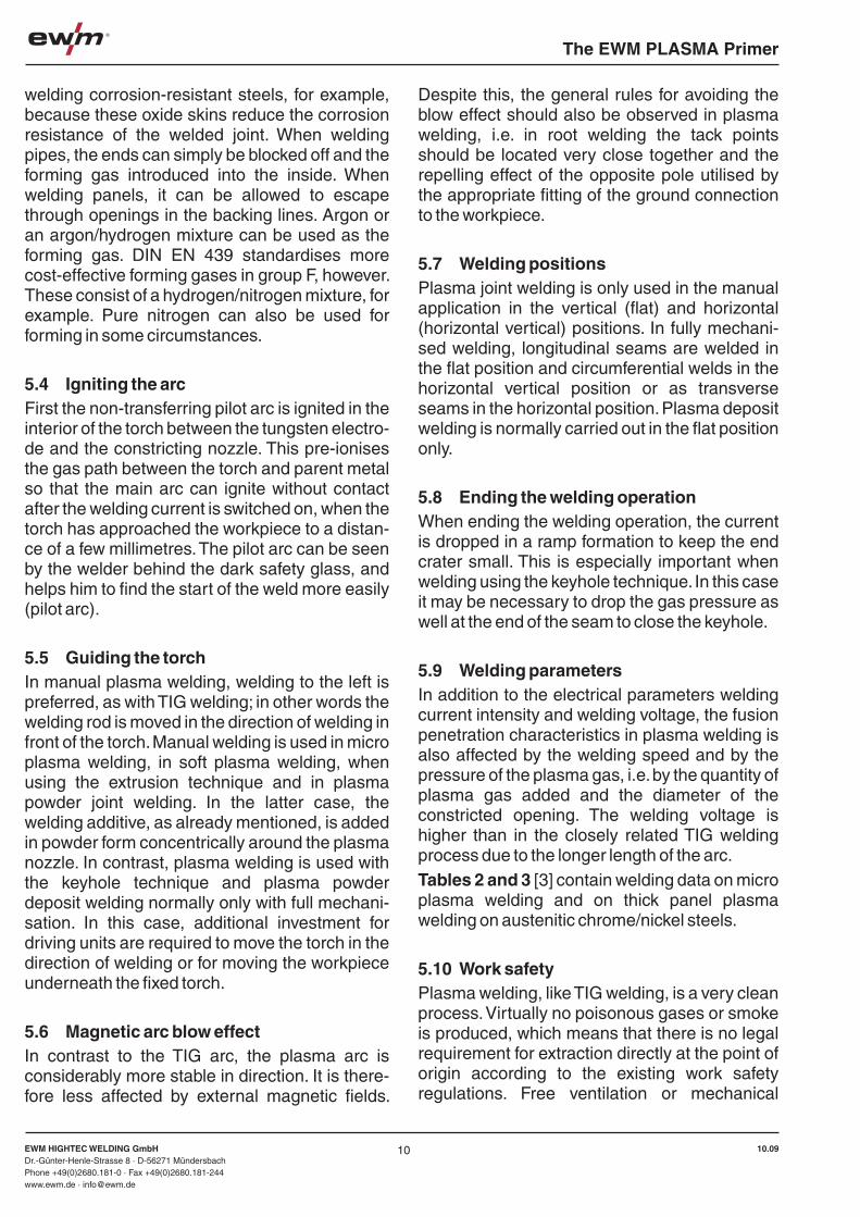
The EWM PLASMA Primer
EWM HIGHTEC WELDING GmbHDr.-Günter-Henle-Strasse 8 · D-56271 MündersbachPhone +49(0)2680.181-0 · Fax +49(0)2680.181-244www.ewm.de · [email protected]
10.09EWM HIGHTEC WELDING GmbHDr.-Günter-Henle-Strasse 8 · D-56271 MündersbachPhone +49(0)2680.181-0 · Fax +49(0)2680.181-244www.ewm.de · [email protected]
10.09
The EWM PLASMA Primer
welding corrosion-resistant steels, for example, because these oxide skins reduce the corrosion resistance of the welded joint. When welding pipes, the ends can simply be blocked off and the forming gas introduced into the inside. When welding panels, it can be allowed to escape through openings in the backing lines. Argon or an argon/hydrogen mixture can be used as the forming gas. DIN EN 439 standardises more cost-effective forming gases in group F, however. These consist of a hydrogen/nitrogen mixture, for example. Pure nitrogen can also be used for forming in some circumstances.
5.4 Igniting the arcFirst the non-transferring pilot arc is ignited in the interior of the torch between the tungsten electro-de and the constricting nozzle. This pre-ionises the gas path between the torch and parent metal so that the main arc can ignite without contact after the welding current is switched on, when the torch has approached the workpiece to a distan-ce of a few millimetres. The pilot arc can be seen by the welder behind the dark safety glass, and helps him to find the start of the weld more easily (pilot arc).
5.5 Guiding the torchIn manual plasma welding, welding to the left is preferred, as with TIG welding; in other words the welding rod is moved in the direction of welding in front of the torch. Manual welding is used in micro plasma welding, in soft plasma welding, when using the extrusion technique and in plasma powder joint welding. In the latter case, the welding additive, as already mentioned, is added in powder form concentrically around the plasma nozzle. In contrast, plasma welding is used with the keyhole technique and plasma powder deposit welding normally only with full mechani-sation. In this case, additional investment for driving units are required to move the torch in the direction of welding or for moving the workpiece underneath the fixed torch.
5.6 Magnetic arc blow effectIn contrast to the TIG arc, the plasma arc is considerably more stable in direction. It is there-fore less affected by external magnetic fields.
Despite this, the general rules for avoiding the blow effect should also be observed in plasma welding, i.e. in root welding the tack points should be located very close together and the repelling effect of the opposite pole utilised by the appropriate fitting of the ground connection to the workpiece.
5.7 Welding positionsPlasma joint welding is only used in the manual application in the vertical (flat) and horizontal (horizontal vertical) positions. In fully mechani-sed welding, longitudinal seams are welded in the flat position and circumferential welds in the horizontal vertical position or as transverse seams in the horizontal position. Plasma deposit welding is normally carried out in the flat position only.
5.8 Ending the welding operationWhen ending the welding operation, the current is dropped in a ramp formation to keep the end crater small. This is especially important when welding using the keyhole technique. In this case it may be necessary to drop the gas pressure as well at the end of the seam to close the keyhole.
5.9 Welding parametersIn addition to the electrical parameters welding current intensity and welding voltage, the fusion penetration characteristics in plasma welding is also affected by the welding speed and by the pressure of the plasma gas, i.e. by the quantity of plasma gas added and the diameter of the constricted opening. The welding voltage is higher than in the closely related TIG welding process due to the longer length of the arc.Tables 2 and 3 [3] contain welding data on micro plasma welding and on thick panel plasma welding on austenitic chrome/nickel steels.
5.10 Work safetyPlasma welding, like TIG welding, is a very clean process. Virtually no poisonous gases or smoke is produced, which means that there is no legal requirement for extraction directly at the point of origin according to the existing work safety regulations. Free ventilation or mechanical
ventilation of the room is sufficient. The welder does need to protect himself against the radiati-on from the arc and against electrical hazards, however. To counteract the infrared and ultravio-let radiation, the plasma welder normally wears a head shield which leaves both hands free for moving the torch and adding the filler metal. The welder’s safety filter is integrated into this protec-tive screen. This filter is standardised in DIN EN 169. There are various safety levels which need to be permanently marked on the glass. In plasma welding, filters in safety levels 9 to 14 are used, depending on the current intensity being used, with level 9 for the lower currents, e.g. for micro plasma welding, and 14 for the higher
current intensities. The greatest electrical hazard arises from the open circuit voltage. This is the highest voltage, which runs between the connec-tion sockets with the power source switched on, when the arc is not burning. After the arc is ignited, the voltage is much lower, in TIG welding only around 12 to 20 Volts, for example. In accor-dance with German accident prevention regula-tions VBG 15, power sources for direct current in normal operation may have a threshold value of the open circuit voltage of max. 113 volts. With alternating current systems, this value is also 113 volts, but the effective value is limited to max. 80 volts. Under increased electrical hazard, such as when welding in small rooms or on large iron masses, lower values apply for alternating current, e.g. a threshold value of 68 volts and an effective value of 48 volts. More modern welding power sources meeting this requirement bear the “S” safety sign in accordance with DIN EN 60974-1. Older power sources may still be marked with “K” (direct current) or “42V” (alterna-ting current). The welder can ensure maximum protection against electric shocks by using undamaged welding gloves made from leather and well insulated work clothes including safety shoes.
5.11 Special features of different materialsPlasma welding is suitable for joint welding a large range of steels and non-iron metals and alloys.
5.11.1 Unalloyed and low-alloy steels
Plasma welding is a good choice for use with these materials, assuming certain special features are taken into account. Due to the deep fusion penetration and the typical edge shapes in plasma welding with large ridges which need to be melted, the weld metal consists to a large extent of melted parent material. With unalloyed steels, such as pipe steels containing little silicon, the weld metal can then be disrupted by an in take-of oxygen. The consequence of this is a metallurgic pore formation in the weld metal.When selecting the batch, care therefore needs to be taken regarding the silicon content, or larger proportions of Si/Mn-alloyed filler metals need to be added.
1110
Workpiece Welding Welding Plasma Shielding Weldingthickness current voltage gas gas speed
mm A V l/min l/min cm/min
0,1 3 21 0,2 5 30
0,2 6 22 0,2 5 30
0,4 14 24 0,2 6 35
0,5 18 23 0,2 6 20
1,0 40 25 0,3 7 35
Edge preparation: Butt weld without gap
Parent metal: X 5 CrNi 18.10
Plasma gas: Argon I1 - DIN EN 439
Shielding gas: Argon/hydrogen R1 - DIN EN 439
Welding position: Flat
Table 2: Welding parameters for manual microplasma welding (values from [5])
Workpiece Welding Welding Plasma Shielding Weldingthickness current voltage gas gas speed
mm A V l/min l/min cm/min
2,5 200 24 1,5 15 80
3,0 210 28 2,5 18 75
4,0 220 27 2,5 18 65
5,0 230 29 2,5 20 45
6,0 240 28 2,8 20 40
8,0 290 28 3,5 20 25
Edge preparation: Butt
Parent metal: X 5 CrNi 18.10
Plasma gas: Argon I1 - DIN EN 439
Shielding gas: Argon/hydrogen R1 - DIN EN 439
Welding position: Flat
Filler metal: For larger gaps with 3 mm sheet metal thickness and over
Table 3: Welding parameters for fully mechanised plasma keyhole welding (values from [5])
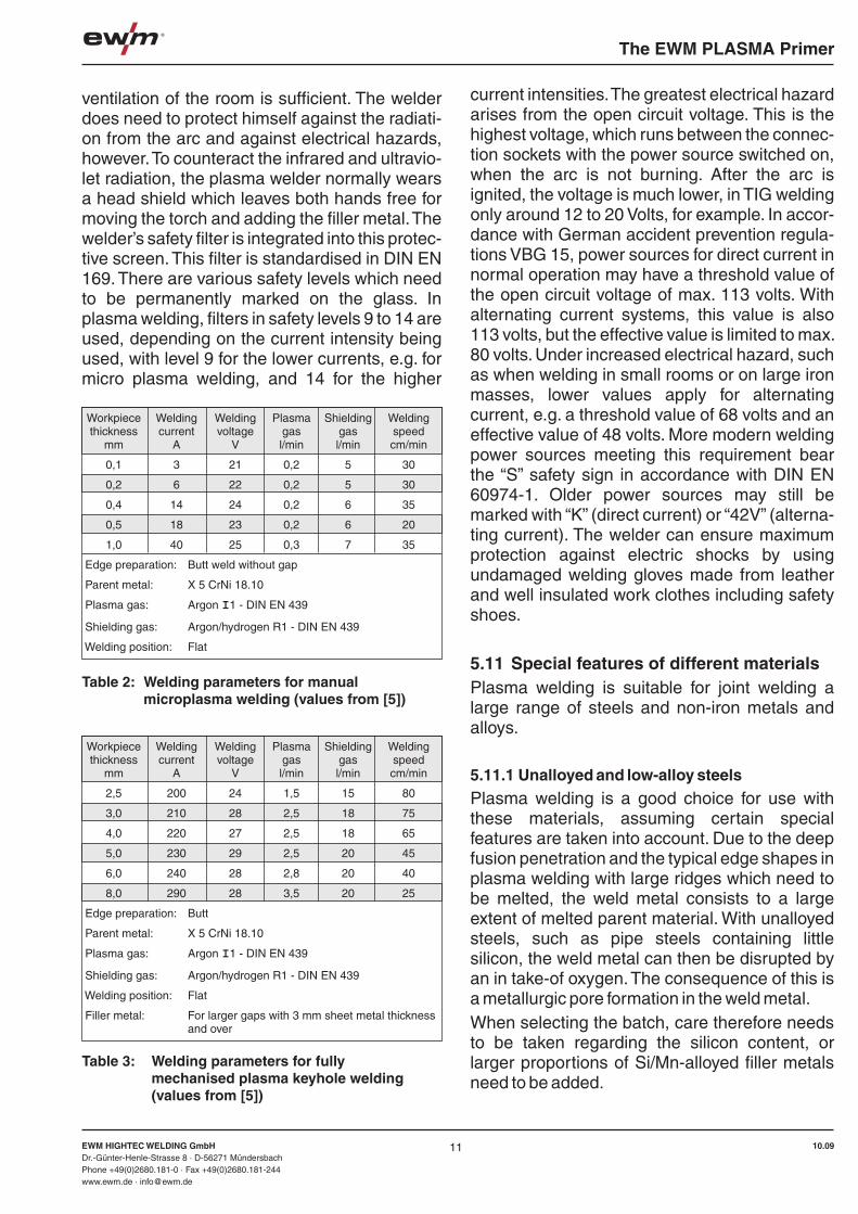
The EWM PLASMA Primer
EWM HIGHTEC WELDING GmbHDr.-Günter-Henle-Strasse 8 · D-56271 MündersbachPhone +49(0)2680.181-0 · Fax +49(0)2680.181-244www.ewm.de · [email protected]
10.09EWM HIGHTEC WELDING GmbHDr.-Günter-Henle-Strasse 8 · D-56271 MündersbachPhone +49(0)2680.181-0 · Fax +49(0)2680.181-244www.ewm.de · [email protected]
10.09
The EWM PLASMA Primer
5.11.2 High-alloy steels
Plasma welding with keyhole technology is ideally suited for use with this material group. The viscosity of the weld metal specific to these materials produces especially flat and finely feathered beads underneath. This means that mechanical backing runs are not normally necessary.The more intensive heat feeding by the concen-trated arc is compensated by the greater welding speed, in comparison to TIG welding, for exam-ple, which means that there is no risk of disad-vantageous effects in the form of a tendency towards heat cracks or reduced resistance to corrosion. For components subsequently expo-sed to a high risk of corrosion, the corrosion skins formed by the welding process must at least be removed on the side touching the product by brushing, blasting, grinding or etching because a greater degree of corrosion could occur under-neath.
5.11.3 Aluminium and aluminium alloys
It is not possible to weld aluminium materials on the minus pole with argon as the shielding gas. The high-melting oxide layer on the pool cannot be dealt with, therefore. Aluminium oxide (Al2 O3) has a melting point of around 2050°C. The parent metal, e.g. pure aluminium, melts at 650°C on the other hand. Aluminium has such a high degree of chemical relationship to oxygen, which means that even if the surface of the parent metal has been freed of oxides before welding by brushing or scraping, skins form on the surface of the pool quickly again. Due to their high melting point, these skins only partially melt directly underneath the arc. This means that the greater part of the seam surface would be cover-ed with a solid layer of aluminium oxide when welding with direct current (- pole). This makes monitoring the pool impossible and makes it more difficult to add filler metal. This oxide layer can be removed by using flux, as in brazing, but this would mean a lot of extra work.When welding with direct current on the plus pole, it is possible to take off and remove this oxide layer via charge carriers in the arc. Here only the ions are the issue as the electrons do not have sufficient kinetic energy for this due to their low mass. Figure 17 shows the flow of charge
carriers in the arc. If the minus pole is on the electrode, the electrons move from the electrode to the workpiece and the residual ions from the workpiece to the electrode. Cleaning effect is not possible with this pole setup. With the poles reversed, on the other hand, the heavy ions hit the surface of the workpiece. They can take off and remove the oxide layer thanks to their kinetic energy. Welding on the hotter plus pole results in
the current loading capacity of the electrode being quite low, however. Thick electrons must be used with semi-cone shaped ends. The fusion penetration is relatively low due to the low current loading capacity. When welding with alternating current the cleaning effect occurs when the positive half-wave is on the electrode. The electrode can then cool down again in the subsequent negative half-wave. This is therefore also known as the cleaning and cooling half-wave. When welding with alternating current, the current-loading capacity is lower than with direct current minus pole welding. However, it is higher than when welding on the plus pole. It has been shown that for sufficient cleaning effect, the entire positive half-wave is not required at all, but that 20% or 30% of the half-wave is sufficient.
This fact has been exploited in modern current sources in which the balance of the two half-waves can be changed in relation to one anot-her, e.g. from 20% plus/80% minus to 80% plus/20% minus. The lower proportion of the plus pole results in a higher level of current loading capacity of the electrode, or with the same current setting, in a longer service life. With these “square-wave sources” it is normally still possible to change the frequency of the artificial alternating current as well, e.g. between 50 Hz and 300 Hz. Increasing the frequency also improves the level of wear on the electrode.The square-wave artificial alternating current has another advantage, however. As the current output wave form is very steep when the polarity is changed, the idle times of the arc in the cros-sover are considerably shorter than with a sine-shaped wave form. The re-ignition is therefore more reliable and the arc is more stable overall. Modern power sources permit the use of direct current in welding, both with sine and square wave-form alternating current.More recently a variant of minus pole welding has also been used, in which shielding gas with a high helium content is used. In manual welding the proportion of helium in the shielding gas needs to be at least 90 % to ensure sufficient pool monitoring for the welder. In machine welding a helium proportion of 70 % is also adequate. When welding on the minus pole under argon, the oxide skin cannot be broken open, as explained above. Due to the high temperature of the energy-rich helium arc, it can be liquefied, however. This means that it is less of a problem. Figure 18 [4] shows a comparison of the surface formation and the fusion penetrati-on in plasma welding of aluminium with the variants described above. When interpreting the results it should be noted that the welds have been carried out using different current intensi-ties.Another special feature in welding the material aluminium is its sensitivity to pores when in the take-up of hydrogen. The relationships are more problematic than when welding steel. Whereas iron can still dissolve hydrogen at 8 cm3/100 g weld metal in the transfer from the liquid to the solid state, aluminium in its solid state dissolves practically no hydrogen at all. This means that all
hydrogen taken up during welding must exit the weld metal before it hardens. Otherwise pores will form in the weld metal.Sources of hydrogen in TIG welding of aluminium are primarily oxide skins on the parent metal. This bind in humidity and must therefore be removed before welding by brushing or scraping. On the other hand, the arc is quieter if there is a thin oxide skin on the surface because this emits
lighter electrons than the pure metal. A compro-mise therefore needs to be found between a stable arc and sufficient protection against pore formation. It has proven useful to remove oxides thoroughly from the workpiece surfaces before welding, but then waiting one or two hours before starting the welding process so that a new thin oxide layer can form. The oxide skins formed on the surface of the welding rods also contribute to pore formation. Filler metals made from alumini-um should therefore be stored carefully and not for too long a period.
1312
Figure 17: Cleaning effect and electron emission work in welding of aluminium alloys
Figure 18: Upper seam sides and fusion penetration in the plasma welding of AlMg3, t=3mm, no filler metal
a) Plasma plus pole weldingI=35A, U=26V, v =40cm/min, sPlasma gas: Ar, shielding gas: 70%Ar / 30%He
b) Plasma minus pole weldingI=70A, U=20V, v =90cm/min, sPlasma gas: 30%Ar / 70%He, shielding gas: He
c) Plasma alternating current weldingI=45A, U=26V, v =40cm/min, sPlasma gas: Ar, shielding gas: 70%Ar / 30%He
Cleaning via kinetic energy Electrode on the plus pole
No cleaning Electrode on the minus pole
Ions
Electrons Ions
Electrons
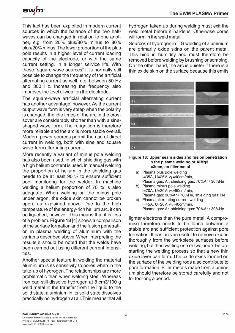
The EWM PLASMA Primer
EWM HIGHTEC WELDING GmbHDr.-Günter-Henle-Strasse 8 · D-56271 MündersbachPhone +49(0)2680.181-0 · Fax +49(0)2680.181-244www.ewm.de · [email protected]
10.09EWM HIGHTEC WELDING GmbHDr.-Günter-Henle-Strasse 8 · D-56271 MündersbachPhone +49(0)2680.181-0 · Fax +49(0)2680.181-244www.ewm.de · [email protected]
10.09
The EWM PLASMA Primer
5.11.2 High-alloy steels
Plasma welding with keyhole technology is ideally suited for use with this material group. The viscosity of the weld metal specific to these materials produces especially flat and finely feathered beads underneath. This means that mechanical backing runs are not normally necessary.The more intensive heat feeding by the concen-trated arc is compensated by the greater welding speed, in comparison to TIG welding, for exam-ple, which means that there is no risk of disad-vantageous effects in the form of a tendency towards heat cracks or reduced resistance to corrosion. For components subsequently expo-sed to a high risk of corrosion, the corrosion skins formed by the welding process must at least be removed on the side touching the product by brushing, blasting, grinding or etching because a greater degree of corrosion could occur under-neath.
5.11.3 Aluminium and aluminium alloys
It is not possible to weld aluminium materials on the minus pole with argon as the shielding gas. The high-melting oxide layer on the pool cannot be dealt with, therefore. Aluminium oxide (Al2 O3) has a melting point of around 2050°C. The parent metal, e.g. pure aluminium, melts at 650°C on the other hand. Aluminium has such a high degree of chemical relationship to oxygen, which means that even if the surface of the parent metal has been freed of oxides before welding by brushing or scraping, skins form on the surface of the pool quickly again. Due to their high melting point, these skins only partially melt directly underneath the arc. This means that the greater part of the seam surface would be cover-ed with a solid layer of aluminium oxide when welding with direct current (- pole). This makes monitoring the pool impossible and makes it more difficult to add filler metal. This oxide layer can be removed by using flux, as in brazing, but this would mean a lot of extra work.When welding with direct current on the plus pole, it is possible to take off and remove this oxide layer via charge carriers in the arc. Here only the ions are the issue as the electrons do not have sufficient kinetic energy for this due to their low mass. Figure 17 shows the flow of charge
carriers in the arc. If the minus pole is on the electrode, the electrons move from the electrode to the workpiece and the residual ions from the workpiece to the electrode. Cleaning effect is not possible with this pole setup. With the poles reversed, on the other hand, the heavy ions hit the surface of the workpiece. They can take off and remove the oxide layer thanks to their kinetic energy. Welding on the hotter plus pole results in
the current loading capacity of the electrode being quite low, however. Thick electrons must be used with semi-cone shaped ends. The fusion penetration is relatively low due to the low current loading capacity. When welding with alternating current the cleaning effect occurs when the positive half-wave is on the electrode. The electrode can then cool down again in the subsequent negative half-wave. This is therefore also known as the cleaning and cooling half-wave. When welding with alternating current, the current-loading capacity is lower than with direct current minus pole welding. However, it is higher than when welding on the plus pole. It has been shown that for sufficient cleaning effect, the entire positive half-wave is not required at all, but that 20% or 30% of the half-wave is sufficient.
This fact has been exploited in modern current sources in which the balance of the two half-waves can be changed in relation to one anot-her, e.g. from 20% plus/80% minus to 80% plus/20% minus. The lower proportion of the plus pole results in a higher level of current loading capacity of the electrode, or with the same current setting, in a longer service life. With these “square-wave sources” it is normally still possible to change the frequency of the artificial alternating current as well, e.g. between 50 Hz and 300 Hz. Increasing the frequency also improves the level of wear on the electrode.The square-wave artificial alternating current has another advantage, however. As the current output wave form is very steep when the polarity is changed, the idle times of the arc in the cros-sover are considerably shorter than with a sine-shaped wave form. The re-ignition is therefore more reliable and the arc is more stable overall. Modern power sources permit the use of direct current in welding, both with sine and square wave-form alternating current.More recently a variant of minus pole welding has also been used, in which shielding gas with a high helium content is used. In manual welding the proportion of helium in the shielding gas needs to be at least 90 % to ensure sufficient pool monitoring for the welder. In machine welding a helium proportion of 70 % is also adequate. When welding on the minus pole under argon, the oxide skin cannot be broken open, as explained above. Due to the high temperature of the energy-rich helium arc, it can be liquefied, however. This means that it is less of a problem. Figure 18 [4] shows a comparison of the surface formation and the fusion penetrati-on in plasma welding of aluminium with the variants described above. When interpreting the results it should be noted that the welds have been carried out using different current intensi-ties.Another special feature in welding the material aluminium is its sensitivity to pores when in the take-up of hydrogen. The relationships are more problematic than when welding steel. Whereas iron can still dissolve hydrogen at 8 cm3/100 g weld metal in the transfer from the liquid to the solid state, aluminium in its solid state dissolves practically no hydrogen at all. This means that all
hydrogen taken up during welding must exit the weld metal before it hardens. Otherwise pores will form in the weld metal.Sources of hydrogen in TIG welding of aluminium are primarily oxide skins on the parent metal. This bind in humidity and must therefore be removed before welding by brushing or scraping. On the other hand, the arc is quieter if there is a thin oxide skin on the surface because this emits
lighter electrons than the pure metal. A compro-mise therefore needs to be found between a stable arc and sufficient protection against pore formation. It has proven useful to remove oxides thoroughly from the workpiece surfaces before welding, but then waiting one or two hours before starting the welding process so that a new thin oxide layer can form. The oxide skins formed on the surface of the welding rods also contribute to pore formation. Filler metals made from alumini-um should therefore be stored carefully and not for too long a period.
1312
Figure 17: Cleaning effect and electron emission work in welding of aluminium alloys
Figure 18: Upper seam sides and fusion penetration in the plasma welding of AlMg3, t=3mm, no filler metal
a) Plasma plus pole weldingI=35A, U=26V, v =40cm/min, sPlasma gas: Ar, shielding gas: 70%Ar / 30%He
b) Plasma minus pole weldingI=70A, U=20V, v =90cm/min, sPlasma gas: 30%Ar / 70%He, shielding gas: He
c) Plasma alternating current weldingI=45A, U=26V, v =40cm/min, sPlasma gas: Ar, shielding gas: 70%Ar / 30%He
Cleaning via kinetic energy Electrode on the plus pole
No cleaning Electrode on the minus pole
Ions
Electrons Ions
Electrons
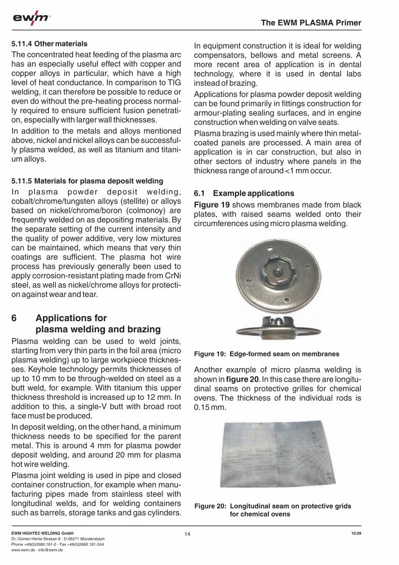
The EWM PLASMA Primer
EWM HIGHTEC WELDING GmbHDr.-Günter-Henle-Strasse 8 · D-56271 MündersbachPhone +49(0)2680.181-0 · Fax +49(0)2680.181-244www.ewm.de · [email protected]
10.09EWM HIGHTEC WELDING GmbHDr.-Günter-Henle-Strasse 8 · D-56271 MündersbachPhone +49(0)2680.181-0 · Fax +49(0)2680.181-244www.ewm.de · [email protected]
10.09
The EWM PLASMA Primer
5.11.4 Other materials
The concentrated heat feeding of the plasma arc has an especially useful effect with copper and copper alloys in particular, which have a high level of heat conductance. In comparison to TIG welding, it can therefore be possible to reduce or even do without the pre-heating process normal-ly required to ensure sufficient fusion penetrati-on, especially with larger wall thicknesses.In addition to the metals and alloys mentioned above, nickel and nickel alloys can be successful-ly plasma welded, as well as titanium and titani-um alloys.
5.11.5 Materials for plasma deposit welding
In plasma powder deposit welding, cobalt/chrome/tungsten alloys (stellite) or alloys based on nickel/chrome/boron (colmonoy) are frequently welded on as depositing materials. By the separate setting of the current intensity and the quality of power additive, very low mixtures can be maintained, which means that very thin coatings are sufficient. The plasma hot wire process has previously generally been used to apply corrosion-resistant plating made from CrNi steel, as well as nickel/chrome alloys for protecti-on against wear and tear.
6 Applications for plasma welding and brazing
Plasma welding can be used to weld joints, starting from very thin parts in the foil area (micro plasma welding) up to large workpiece thicknes-ses. Keyhole technology permits thicknesses of up to 10 mm to be through-welded on steel as a butt weld, for example. With titanium this upper thickness threshold is increased up to 12 mm. In addition to this, a single-V butt with broad root face must be produced.In deposit welding, on the other hand, a minimum thickness needs to be specified for the parent metal. This is around 4 mm for plasma powder deposit welding, and around 20 mm for plasma hot wire welding.Plasma joint welding is used in pipe and closed container construction, for example when manu-facturing pipes made from stainless steel with longitudinal welds, and for welding containers such as barrels, storage tanks and gas cylinders.
In equipment construction it is ideal for welding compensators, bellows and metal screens. A more recent area of application is in dental technology, where it is used in dental labs instead of brazing.Applications for plasma powder deposit welding can be found primarily in fittings construction for armour-plating sealing surfaces, and in engine construction when welding on valve seats.Plasma brazing is used mainly where thin metal-coated panels are processed. A main area of application is in car construction, but also in other sectors of industry where panels in the thickness range of around <1 mm occur.
6.1 Example applicationsFigure 19 shows membranes made from black plates, with raised seams welded onto their circumferences using micro plasma welding.
Another example of micro plasma welding is shown in figure 20. In this case there are longitu-dinal seams on protective grilles for chemical ovens. The thickness of the individual rods is 0.15 mm.
14
Figure 21 shows internal and external round seams on fittings for heating unit construction which have been joined using plasma joint welding.
Figure 22 shows the application of manual plasma brazing in the automobile industry on the door sill of a BMW car body. The filler metal is added manually in this case in the form of rods.
6.2 Comparison with TIG weldingThere is an obvious comparison between plasma welding and the closely related TIG welding process. As well as the high welding speed of the plasma process already mentio-ned, there are other advantages, which are balanced out by several disadvantages, howe-ver. A comparison of advantages of disadvanta-ges are given in table 4.
15
Figure 19: Edge-formed seam on membranes
Figure 20: Longitudinal seam on protective grids for chemical ovens
Figure 21: Internal and external seams on fittings for heating unit construction
Figure 22: Manual plasma brazing on the door sill of a BMW car body
• Higher investment costs
• Torches difficult to use at higher output levels
• Less suitable for out-of-position welding
Plasma welding (in comparison to TIG welding)
Advantages Disadvantages
• Reduced sensitivity in comparison to changes in arc length
• Greater arc stability
• Deeper fusion penetration and more concentrated heat feeding
• Longer service life of the tungsten electrode
• Easier to locate the start of the weld seam via a pilot arc
Table 4: Comparison between TIG and plasma welding in joint welding
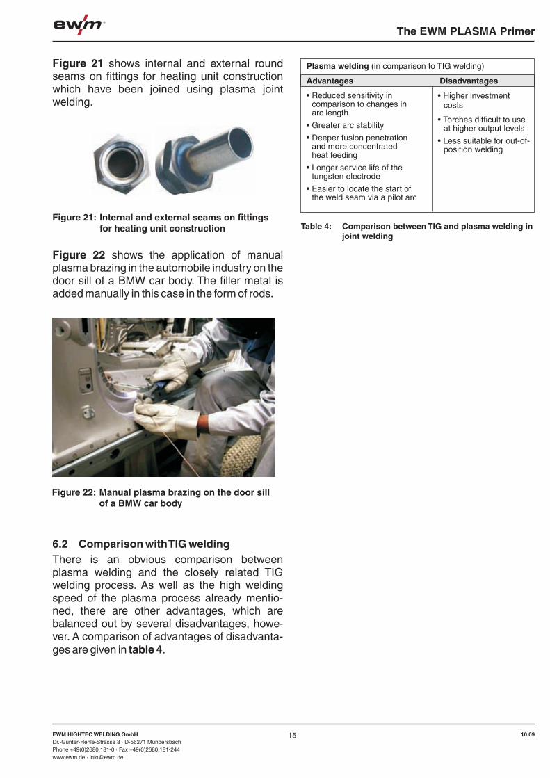
The EWM PLASMA Primer
EWM HIGHTEC WELDING GmbHDr.-Günter-Henle-Strasse 8 · D-56271 MündersbachPhone +49(0)2680.181-0 · Fax +49(0)2680.181-244www.ewm.de · [email protected]
10.09EWM HIGHTEC WELDING GmbHDr.-Günter-Henle-Strasse 8 · D-56271 MündersbachPhone +49(0)2680.181-0 · Fax +49(0)2680.181-244www.ewm.de · [email protected]
10.09
The EWM PLASMA Primer
16
7 Literature[[1] Killing, R.: Handbuch der Schweißverfahren Band 1: Lichtbogenschweißverfahren (Handbook of Welding Processes Volume 1: Arc welding processes)Fachbuchreihe Schweißtechnik Band 76/I, (Specialist book series on welding technology, volume 76/I)DVS-Verlag Düsseldorf 1999[2] Chruszez, M, R. Killing, H. Köstermann and J. Marksmann: Plasma-Pulver-Verbindungsschweißen – ein Verfahren mit besonderen Einsatzbereichen (Plasma power joint welding – a process with special applications)DVS-Berichte Band 194 (German Welding Association reports, volume 194), p 21-26, DVS-Verlag Düsseldorf 1998[3] Aichele, G.: Leistungskennwerte für Schweißen und Schneiden, Fachbuchreihe Schweißtechnik Band 72, (Performance characteristics for welding and cutting, Specialist book series on welding technology, volume 72)DVS-Verlag Düsseldorf 1994[4] Dzelnitzki, D.: Plasma welding of aluminium – direct current or alternating currentDVS-Jahrbuch Schweißtechnik 2000 (German Welding Association Yearbook of Welding Technology 2000), p.141-156DVS-Verlag Düsseldorf 1999
8 ImprintThe PLASMA Primer, 2nd edition 2009From the EWM Knowledge range of publications – All about welding: All rights reserved.Reprinting, including extracts, is forbidden. No part of this brochure may be reproduced or electronically processed, reproduced or distributed in any form (photocopy, microfilm or any other procedure) without the written permission of EWM.
© EWM HIGHTEC WELDING GmbHDr.-Günter-Henle-Str. 8 · D-56271 MündersbachFon: +49(0)2680.181-0 · Fax: +49(0)2680.181-244mailto:[email protected] · http://www.ewm.de

! !Notizen Notizen

For more information please visit our website at www.ewm-group.comwww.ewm-tv.de
EWM Schweißtechnik-Handels-GmbHSachsstraße 28 50259 Pulheim · GermanyTel: +49 2234 697-047 · Fax: -048www.ewm-group.com/handel · [email protected]
EWM Schweißtechnik Handels GmbHHeinkelstraße 8 89238 Neu-Ulm · GermanyTel: +49 731 7047939-0 · Fax: -15www.ewm-group.com/handel · [email protected]
EWM HIGHTEC WELDING s.r.o.Tr. 9. kvetna 718 / 31 407 53 Jiříkov · Czech RepublicTel: +420 412 358-551 · Fax: -20www.ewm-group.com/cz · [email protected]
EWM HIGHTEC WELDING UK Ltd.Unit 2B Coopies Way Coopies Lane Industrial EstateMorpeth · Northumberland · NE61 6JN · Great BritainTel: +44 1670 505875 · Fax: -514305www.ewm-group.com/uk · [email protected]
EWM HIGHTEC WELDING (Kunshan) Ltd.10 Yuanshan Road, Kunshan New & High-tech Industry Development ZoneKunshan · Jiangsu · 215300 · People´s Republic of ChinaTel: +86 512 57867-188 · Fax: -182www.ewm-group.com/cn · [email protected]
EWM HIGHTEC WELDING GmbH Dr. Günter-Henle-Straße 856271 MündersbachGermanyTel: +49 2680 181-0 · Fax: -244 www.ewm-group.com · [email protected]
EWM Schweißtechnik-Handels-GmbHIn der Florinskaul 14-16 56218 Mülheim-Kärlich · GermanyTel: +49 261 988898-0 · Fax: -20www.ewm-group.com/handel · [email protected]
EWM HIGHTEC WELDING GmbHBranch Seesen Lindenstraße 1a 38723 Seesen-Rhüden · GermanyTel: +49 5384 90798-0 · Fax: -20www.ewm-group.com/handel · [email protected]
EWM HIGHTEC WELDING Sales s.r.o.Prodejní a poradenské centrum Tyršova 2106 256 01 Benešov u Prahy · Czech RepublicTel: +420 317 729-517 · Fax: -712www.ewm-group.com/cz · [email protected]
EWM HIGHTEC WELDING GmbHFichtenweg 14810 Gmunden · AustriaTel: +43 7612 778 02-0 · Fax: -20www.ewm-group.com/at · [email protected]
EWM HIGHTEC WELDING FZCORegional Offi ce Middle EastJAFZA View 18 F 14 05 · P.O. Box 262851 Jebel Ali Free Zone · Dubai · United Arab EmiratesTel: +971 4 8857-789 · Fax: -500www.ewm-group.com/me · [email protected]
Sales, Consultancy, Service
© E
WM
HIG
HTE
C W
ELD
ING
Gm
bH 2
010
· WM
.055
1.01
· 01
.201
0 · W
e re
serv
e th
e rig
ht to
mak
e am
endm
ents