58820849_SINAMICS_G120_at_S7-300400-PN_DOKU_v20_en
70
Applications & Tools Answers for industry. Cover Control of speed of a SINAMICS G120, G120C or G120D to an S7-300/400 in STEP 7 V5 via PROFINET SINAMICS G120 / G120C / G120D (with FW ≥ 4.3.2) SIMATIC S7-300/400 Application Description August 2012
-
Upload
heller-arias -
Category
Documents
-
view
88 -
download
9
Transcript of 58820849_SINAMICS_G120_at_S7-300400-PN_DOKU_v20_en

Applications & Tools
Answers for industry.
Cover
Control of speed of a SINAMICS G120, G120C or G120D to an S7-300/400 in STEP 7 V5 via PROFINET
SINAMICS G120 / G120C / G120D (with FW ≥ 4.3.2) SIMATIC S7-300/400
Application Description August 2012
2 SINAMICS G120C at S7-300/400
V2.0, Entry ID: 58820849
Co
pyr
igh
t
Sie
me
ns
AG
20
12
All
righ
ts r
ese
rve
d
Siemens Industry Online Support
This document is taken from Siemens Industry Online Support. The following link takes you directly to the download page of this document:
http://support.automation.siemens.com/WW/view/en/58820849
Caution: The functions and solutions described in this entry are mainly limited to the realization of the automation task. In addition, please note that suitable security measures in compliance with the applicable Industrial Security standards must be taken if your system is interconnected with other parts of the plant, the company's network or the Internet. More information can be found under entry ID 50203404.
http://support.automation.siemens.com/WW/view/en/50203404
For further information on this topic, you may also actively use our Technical Forum in the Siemens Industry Online Support. Share your questions, suggestions or problems and discuss them with our strong forum community:
http://www.siemens.com/forum-applications

SINAMICS G120C at S7-300/400 V2.0, Entry ID: 58820849 3
Co
pyr
igh
t
Sie
me
ns
AG
20
12
All
righ
ts r
ese
rve
d
s
SIMATIC, SINAMICS
SINAMICS G120 / G120C / G120D at an S7-300/400 Controller
Task
1
Solution
2 Functional Mechanisms of the Application
3
Setting up and Commissioning the Application
4
Operation of the Application
5
Configuration and Settings
6
Links & Literature
7
History
8
Table of Contents
4 SINAMICS G120C at S7-300/400
V2.0, Entry ID: 58820849
Co
pyr
igh
t
Sie
me
ns
AG
20
12
All
righ
ts r
ese
rve
d
Warranty and Liability
Note The application examples are not binding and do not claim to be complete regarding configuration, equipment and any eventuality. The application examples do not represent customer-specific solutions. They are only intended to provide support for typical applications. You are responsible for ensuring that the described products are used correctly. These application examples do not relieve you of your responsibility to use sound practices in application, installation, operation and maintenance. When using these application examples, you recognize that we will not be liable for any damage/claims beyond the liability clause described. We reserve the right to make changes to these application examples at any time without prior notice. If there are any deviations between the recommendations provided in this application example and other Siemens publications (e.g. catalogs), the contents of the other documents shall have priority.
We do not accept any liability for the information contained in this document.
Any claims against us – based on whatever legal reason – resulting from the use of the examples, information, programs, engineering and performance data etc., described in this application example shall be excluded. Such an exclusion shall not apply in the case of mandatory liability, e.g. under the German Product Liability Act (“Produkthaftungsgesetz”), in case of intent, gross negligence, or injury of life, body or health, guarantee for the quality of a product, fraudulent concealment of a deficiency or violation of fundamental contractual obligations (“wesentliche Vertragspflichten”). The damages for a breach of a substantial contractual obligation are, however, limited to the foreseeable damage, typical for the type of contract, except in the event of intent or gross negligence or injury to life, body or health. The above provisions do not imply a change in the burden of proof to your detriment.
It is not permissible to transfer or copy these application examples or excerpts thereof without express authorization from Siemens Industry Sector.
Table of Contents
SINAMICS G120C at S7-300/400 V2.0, Entry ID: 58820849 5
Co
pyr
igh
t
Sie
me
ns
AG
20
12
All
righ
ts r
ese
rve
d
Table of Contents Warranty and Liability ................................................................................................. 4 Table of Contents......................................................................................................... 5 1 Task..................................................................................................................... 7 2 Solution............................................................................................................... 8
2.1 Overview of the general solution.......................................................... 8 2.2 Description of the core functionality ..................................................... 9 2.2.1 Configuring the communication............................................................ 9
SIMATIC S7-300/400 ........................................................................... 9 SINAMICS G120 .................................................................................. 9
2.2.2 Data exchange ..................................................................................... 9 Cyclic process data exchange ........................................................... 10 Acyclic data exchange (parameter access) ....................................... 10
2.3 Hardware and software components used......................................... 11 Sample files and projects ................................................................... 12
3 Setting up and Commissioning the Application .......................................... 14 3.1 Wiring ................................................................................................. 14 3.2 IP addresses and PN names ............................................................. 15 3.3 Settings on PG/PC ............................................................................. 15 3.4 Downloading the SIMATIC program .................................................. 16 3.5 Downloading the SINAMICS configuration ........................................ 20 3.5.1 Preparation for using the network connection of the PG/PC ............. 20 3.5.2 Preparations for using the USB connection of the PG/PC................. 23 3.5.3 Downloading the configuration into the SINAMICS G120.................. 26
4 Operation of the Application .......................................................................... 28 4.1 Prerequisites ...................................................................................... 28 4.2 Operation of the Application............................................................... 28 4.3 Monitoring and parameter access via operator panel........................ 30 4.3.1 Screens and screen navigation.......................................................... 30 4.3.2 Process data exchange...................................................................... 31
Control and status word ..................................................................... 31 Setpoint and actual values ................................................................. 32
4.3.3 Parameter access .............................................................................. 34 Reading/writing parameters ............................................................... 34 Fault buffer ......................................................................................... 36
5 Functional Mechanisms of the Application .................................................. 37 5.1 Functionality of process data exchange............................................. 38 5.1.1 Accessing process data in the user program of the S7-300/400 ....... 39 5.1.2 Standardizing the setpoint and actual values .................................... 39 5.1.3 Control and status word ..................................................................... 40 5.1.4 FB 10 “PZD_G120_Tel_352” ............................................................. 42 5.2 Change-over to “Siemens Telegram 1” (with FB11) .......................... 45 5.3 Parameter access functionality .......................................................... 46 5.3.1 FB 20 “Parameter_Access”................................................................ 47 5.3.2 The DBs “read/write_drive_parameters” and
“answer_from_drive” .......................................................................... 51 5.4 Function of the further blocks in the example projects....................... 54
6 Configuration and Settings ............................................................................ 55 6.1 Configuring the S7-300/400 controller ............................................... 55 6.2 Configuring the SINAMICS G120 drive.............................................. 62

Table of Contents
6 SINAMICS G120C at S7-300/400
V2.0, Entry ID: 58820849
Co
pyr
igh
t
Sie
me
ns
AG
20
12
All
righ
ts r
ese
rve
d
7 Links & Literature ............................................................................................ 69 8 History............................................................................................................... 70

1 Task
SINAMICS G120C at S7-300/400 V2.0, Entry ID: 58820849 7
Co
pyr
igh
t
Sie
me
ns
AG
20
12
All
righ
ts r
ese
rve
d
1 Task The SIMATIC S7 300/400 can be operated as a PROFINET controller. A SINAMICS G120, SINAMICS G120C, SINAMICS G120D or SINAMICS G120P drive can be used here as PROFINET device and be controlled by the S7-300/400.
This application example illustrates how to configure SINAMICS G120/G120C/ G120D/G120P and S7-300/400, start it up, and access process data and parameters.
Overview of the automation task
The following figure gives an overview of the automation task:
Figure 1-1
MPI, PROFIBUS or Ethernet
PROFINET
Requirements for the automation task
Table 1-1
Requirement Explanation
Access to process data The SINAMICS G120 shall be switched on and off via the control word, and the speed value is to be specified as fast as possible.
Access to parameters Read and write access from/to the parameters in the SINAMICS G120 by the S7-300/400 (in this example: ramp-up and ramp-down time) should be possible and be performed using as few resources as possible, i.e. small communication load.
Safety function of the SINAMICS G120
The SINAMICS G120 converters have the option of performing a fail-safe shutdown (e.g. emergency-stop).
2 Solution
2.1 Overview of the general solution
8 SINAMICS G120C at S7-300/400
V2.0, Entry ID: 58820849
Co
pyr
igh
t
Sie
me
ns
AG
20
12
All
righ
ts r
ese
rve
d
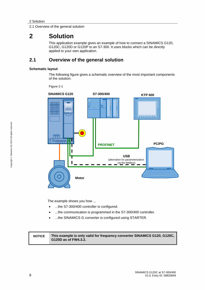
2 Solution This application example gives an example of how to connect a SINAMICS G120, G120C, G120D or G120P to an S7-300. It uses blocks which can be directly applied to your own application.
2.1 Overview of the general solution
Schematic layout
The following figure gives a schematic overview of the most important components of the solution:
Figure 2-1
USB(alternative for parameterization
via the fieldbus)
PROFINET
SINAMICS G120 S7-300/400 KTP 600
Motor
PC/PG
The example shows you how ...
• ...the S7-300/400 controller is configured.
• ...the communication is programmed in the S7-300/400 controller.
• ...the SINAMICS G converter is configured using STARTER.
NOTICE This example is only valid for frequency converter SINAMICS G120, G120C, G120D as of FW4.3.2.

2 Solution
2.2 Description of the core functionality
SINAMICS G120C at S7-300/400 V2.0, Entry ID: 58820849 9
Co
pyr
igh
t
Sie
me
ns
AG
20
12
All
righ
ts r
ese
rve
d
2.2 Description of the core functionality
2.2.1 Configuring the communication
TIA (Totally Integrated Automation)
The program for SIMATIC S7-300/400 and the configuration of the SINAMICS G120 are centrally stored in a STEP 7. The respectively required editors are called up via the STEP 7 Manager.
SIMATIC S7-300/400
SIMATIC S7-300/400 in this example is programmed with STEP 7 V5.
In HW Config, the SIMATIC S7 the stations connected via PROFINET, such as SINAMICS G120, are configured, and the communication is defined. One of several message frame types can be selected here for the data exchange. It is important that the same message frame type is selected here as for the SINAMICS G120 configuration.
When inserting SINAMICS G120 into the SIMATIC project, the I/O addresses used by the S7-300/400 for accessing the SINAMICS G120 are also specified.
SINAMICS G120
The configuration of SINAMICS G120 is performed using the STARTER commissioning tool.
For SINAMICS G120 one of several message frame types can be selected for the data exchange. This defines which data is transmitted or received in which order. It is important that the same message frame type is selected when configuring the SIMATIC S7-300/400.
2.2.2 Data exchange
Data exchange between SIMATIC G120 and SIMATIC S7-300/400 occurs in two areas:
• Process data, i.e. control word(s) and setpoint(s), or status word(s) and real value(s)
• Parameter area, i.e. reading/writing of parameter values
Note The two areas, process data and parameters, are independent from each other and can also be used individually.
2 Solution
2.2 Description of the core functionality
10 SINAMICS G120C at S7-300/400
V2.0, Entry ID: 58820849
Co
pyr
igh
t
Sie
me
ns
AG
20
12
All
righ
ts r
ese
rve
d
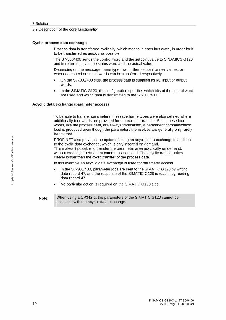
Cyclic process data exchange
Process data is transferred cyclically, which means in each bus cycle, in order for it to be transferred as quickly as possible.
The S7-300/400 sends the control word and the setpoint value to SINAMICS G120 and in return receives the status word and the actual value.
Depending on the message frame type, two further setpoint or real values, or extended control or status words can be transferred respectively.
• On the S7-300/400 side, the process data is supplied as I/O input or output words.
• In the SIMATIC G120, the configuration specifies which bits of the control word are used and which data is transmitted to the S7-300/400.
Acyclic data exchange (parameter access)
To be able to transfer parameters, message frame types were also defined where additionally four words are provided for a parameter transfer. Since these four words, like the process data, are always transmitted, a permanent communication load is produced even though the parameters themselves are generally only rarely transferred.
PROFINET also provides the option of using an acyclic data exchange in addition to the cyclic data exchange, which is only inserted on demand. This makes it possible to transfer the parameter area acyclically on demand, without creating a permanent communication load. The acyclic transfer takes clearly longer than the cyclic transfer of the process data.
In this example an acyclic data exchange is used for parameter access.
• In the S7-300/400, parameter jobs are sent to the SIMATIC G120 by writing data record 47, and the response of the SIMATIC G120 is read in by reading data record 47.
• No particular action is required on the SIMATIC G120 side.
Note When using a CP342-1, the parameters of the SIMATIC G120 cannot be accessed with the acyclic data exchange.
2 Solution
2.3 Hardware and software components used
SINAMICS G120C at S7-300/400 V2.0, Entry ID: 58820849 11
Co
pyr
igh
t
Sie
me
ns
AG
20
12
All
righ
ts r
ese
rve
d
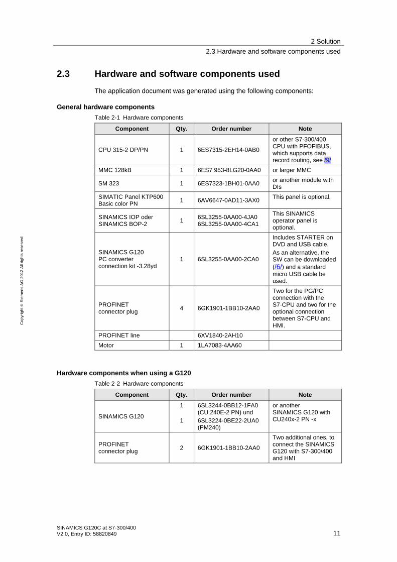
2.3 Hardware and software components used
The application document was generated using the following components:
General hardware components
Table 2-1 Hardware components
Component Qty. Order number Note
CPU 315-2 DP/PN 1 6ES7315-2EH14-0AB0
or other S7-300/400 CPU with PFOFIBUS, which supports data record routing, see /9/
MMC 128kB 1 6ES7 953-8LG20-0AA0 or larger MMC
SM 323 1 6ES7323-1BH01-0AA0 or another module with DIs
SIMATIC Panel KTP600 Basic color PN
1 6AV6647-0AD11-3AX0 This panel is optional.
SINAMICS IOP oder SINAMICS BOP-2
1 6SL3255-0AA00-4JA0 6SL3255-0AA00-4CA1
This SINAMICS operator panel is optional.
SINAMICS G120 PC converter connection kit -3.28yd
1 6SL3255-0AA00-2CA0
Includes STARTER on DVD and USB cable. As an alternative, the SW can be downloaded (/6/) and a standard micro USB cable be used.
PROFINET connector plug
4 6GK1901-1BB10-2AA0
Two for the PG/PC connection with the S7-CPU and two for the optional connection between S7-CPU and HMI.
PROFINET line 6XV1840-2AH10
Motor 1 1LA7083-4AA60
Hardware components when using a G120
Table 2-2 Hardware components
Component Qty. Order number Note
SINAMICS G120
1 1
6SL3244-0BB12-1FA0 (CU 240E-2 PN) und 6SL3224-0BE22-2UA0 (PM240)
or another SINAMICS G120 with CU240x-2 PN -x
PROFINET connector plug
2 6GK1901-1BB10-2AA0
Two additional ones, to connect the SINAMICS G120 with S7-300/400 and HMI

2 Solution
2.3 Hardware and software components used
12 SINAMICS G120C at S7-300/400
V2.0, Entry ID: 58820849
Co
pyr
igh
t
Sie
me
ns
AG
20
12
All
righ
ts r
ese
rve
d
Hardware components when using a G120C
Table 2-3 Hardware components
Component Qty. Order number Note
SINAMICS G120C 1 6SL3210-1KE14-3UF1 or another SINAMICS G120C with PROFINET
PROFINET connector plug
2 6GK1901-1BB10-2AA0
Two additional ones, to connect the SINAMICS G120 with S7-300/400 and HMI
Hardware components when using a G120D
Table 2-4 Hardware components
Component Qty. Order number Note
SINAMICS G120D
1 1
6SL3544-0FB20-1FA0 (CU 240D-2 PN) and 6SL3525-0PE21-5AA1 (PM250D)
or any other PM250D power unit
PROFINET connector plug M12
2 6GK1901-0DB20-6AA0 or 3RK1902-2DA00
straight or angled
Connector and cable for network and motor connections
Please refer to these in the operating instructions (/7/) Chapter 4.2.3 Connections and cables.
Software components
Table 2-6 Software components
Component Qty. Order number Note
SIMATIC STEP 7 V5.5 SP2
1 Floating License 6ES7810-4CC10-0YA5
STARTER V4.3.1.2
1 6SL3072-0AA00-0AG0 Free download: see /6/
WinCC flexible Version: 2008 SP3
1 6AV6613-0AA51-3CA5
Sample files and projects
The following list includes all files and projects used in this example /4/.
The four project files only differ in the SINAMICS G120 configured in it. The documentation applies for all types of the SINAMICS G120.
Table 2-7 Sample files and projects
Component Note
58820849_SINAMICS_G120_at_S7-300400-PN_CODE_v20.zip This zip file contains the STEP 7 project with SINAMICS G120.

2 Solution
2.3 Hardware and software components used
SINAMICS G120C at S7-300/400 V2.0, Entry ID: 58820849 13
Co
pyr
igh
t
Sie
me
ns
AG
20
12
All
righ
ts r
ese
rve
d
Component Note
58820849_SINAMICS_G120C_at_S7-300400-PN_CODE_v20.zip This zip file contains the STEP 7 project with SINAMICS G120C.
58820849_SINAMICS_G120D_at_S7-300400-PN_CODE_v20.zip This zip file contains the STEP 7 project with SINAMICS G120D.
58820849_SINAMICS_G120_at_S7-300400_SHORT-DOKU_v20_de.pdf Short documentation for experienced users
58820849_SINAMICS_G120_at_S7-300400-PN_DOKU_v20_de.pdf This document
CAUTION The example projects have been designed for usage with the example components listed in Table 2-1. Converter and/or motor can be damaged or destroyed if a SINAMICS G120 with a different output or a different motor is connected, without adjusting the respective parameters.

3 Setting up and Commissioning the Application
3.1 Wiring
14 SINAMICS G120C at S7-300/400
V2.0, Entry ID: 58820849
Co
pyr
igh
t
Sie
me
ns
AG
20
12
All
righ
ts r
ese
rve
d
3 Setting up and Commissioning the Application
Notes In the screenshots and graphics below, a general project name “G120_at_S7-300400”, or “SINAMICS G120” respectively, is used. In example projects, the respectively used SINAMICS type is specified.
3.1 Wiring
The figure below shows the hardware setup of the application.
Figure 3-1
L1L2L3N
PE
24V0V
PB PN PN CPU 315-2 PN/DP
L1 L2 L3 PE
U2 V2 W2 PE PN PN
SINAMICSG120
MY
L+ M PN
SIMATIC PanelKTP600
on off2 off3 Ack Rev 0 n+ n-
L+ MSM323
E 0.0 0.1 0.2 0.3 0.4 0.5 0.6 0.7 M
USB
PN USB
PG/PC
USB lineis optional.
DI COM 1
DI COM 2
GND
DI 4
+24 V OUT
DI 5F-DI1)
1) F-DI not for CU240B-2 PN
Notes • The setup guidelines in the SINAMICS G120 manual (see /7/) and SIMATIC must generally be followed.

3 Setting up and Commissioning the Application
3.2 IP addresses and PN names
SINAMICS G120C at S7-300/400 V2.0, Entry ID: 58820849 15
Co
pyr
igh
t
Sie
me
ns
AG
20
12
All
righ
ts r
ese
rve
d
3.2 IP addresses and PN names
The following IP addresses and device names are used in the example:
Table 3-1
IP Component Device Name
192.168.0.1 S7-CPU S7-CPU
192.168.0.2 CU240E-2PN G120xCU240Ex2
192.168.0.3 KTP600 KTP600
192.168.0.200 PG/PC
The network mask is always 255.255.255.0 and no router is used.
3.3 Settings on PG/PC
Table 3-2
Action Screenshots / Remarks
Set the fixed TCP/IP address 192.168.0.200 and the network mask 255.255.255.0 in the Windows settings for the network card to be used. You may also enter any other IP address (192.168.0.x).
3 Setting up and Commissioning the Application
3.4 Downloading the SIMATIC program
16 SINAMICS G120C at S7-300/400
V2.0, Entry ID: 58820849
Co
pyr
igh
t
Sie
me
ns
AG
20
12
All
righ
ts r
ese
rve
d
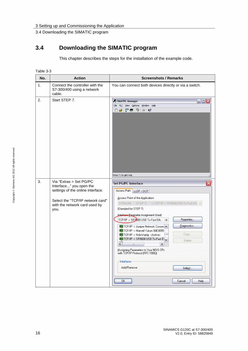
3.4 Downloading the SIMATIC program
This chapter describes the steps for the installation of the example code.
Table 3-3
No. Action Screenshots / Remarks
1. Connect the controller with the S7-300/400 using a network cable.
You can connect both devices directly or via a switch.
2. Start STEP 7.
3. Via “Extras > Set PG/PC Interface...” you open the settings of the online interface. Select the “TCP/IP network card” with the network card used by you.

3 Setting up and Commissioning the Application
3.4 Downloading the SIMATIC program
SINAMICS G120C at S7-300/400 V2.0, Entry ID: 58820849 17
Co
pyr
igh
t
Sie
me
ns
AG
20
12
All
righ
ts r
ese
rve
d
No. Action Screenshots / Remarks
4. Call up the “Edit Ethernet Node…” dialog.
5. • Click on “Browse...” – Select the CPU and
click OK.
• Enter the IP address 192.168.0.1 and the subnet mask 255.255.255.0, and click on “Assign IP Configuration”.
• Enter the device name “s7-cpu” and click on “Assign Name”.
Exit the dialog by clicking “Close”.
6. Click on “Accessible Nodes”.
3 Setting up and Commissioning the Application
3.4 Downloading the SIMATIC program
18 SINAMICS G120C at S7-300/400
V2.0, Entry ID: 58820849
Co
pyr
igh
t
Sie
me
ns
AG
20
12
All
righ
ts r
ese
rve
d
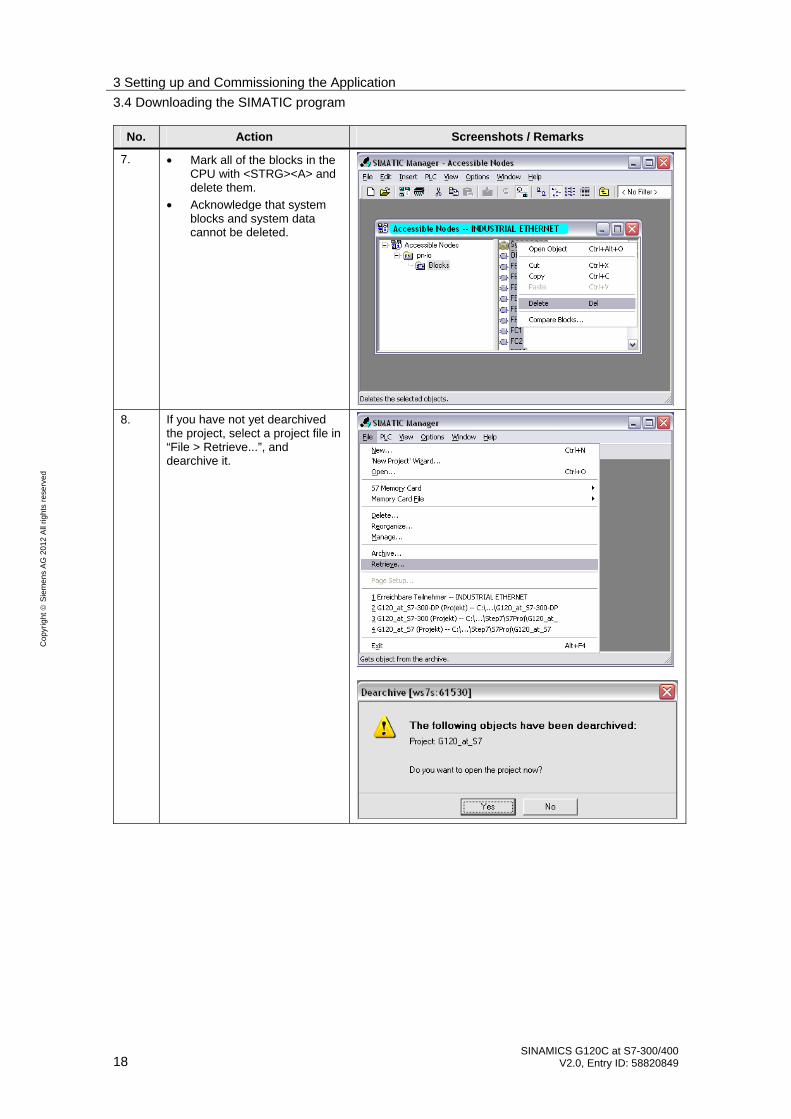
No. Action Screenshots / Remarks
7. • Mark all of the blocks in the CPU with <STRG><A> and delete them.
• Acknowledge that system blocks and system data cannot be deleted.
8. If you have not yet dearchived the project, select a project file in “File > Retrieve...”, and dearchive it.

3 Setting up and Commissioning the Application
3.4 Downloading the SIMATIC program
SINAMICS G120C at S7-300/400 V2.0, Entry ID: 58820849 19
Co
pyr
igh
t
Sie
me
ns
AG
20
12
All
righ
ts r
ese
rve
d
No. Action Screenshots / Remarks
9. • Open the project, select the “Blocks” folder and clock on “Download” or “Blocks” respectively.
• Also download the system data!
10. Restart the CPU after downloading.
11. If you want to use the panel, assign the address 192.168.0.3 and load it in the HMI configuration.
3 Setting up and Commissioning the Application
3.5 Downloading the SINAMICS configuration
20 SINAMICS G120C at S7-300/400
V2.0, Entry ID: 58820849
Co
pyr
igh
t
Sie
me
ns
AG
20
12
All
righ
ts r
ese
rve
d
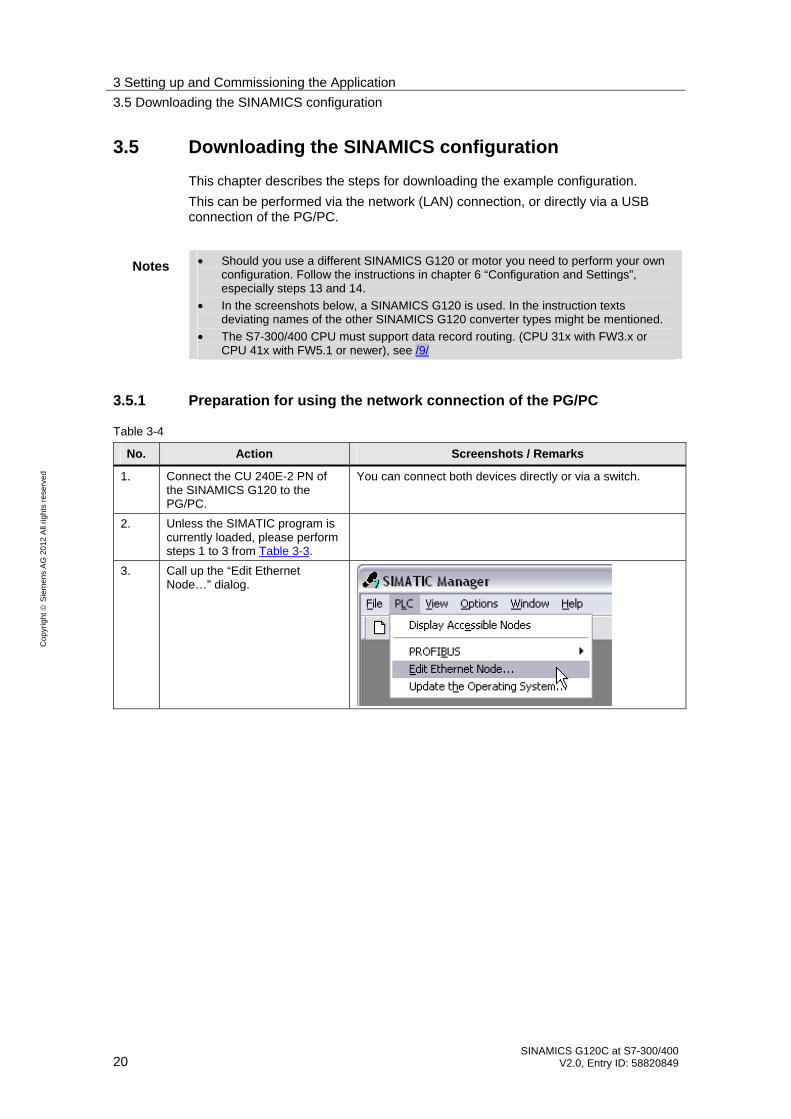
3.5 Downloading the SINAMICS configuration
This chapter describes the steps for downloading the example configuration.
This can be performed via the network (LAN) connection, or directly via a USB connection of the PG/PC.
Notes • Should you use a different SINAMICS G120 or motor you need to perform your own configuration. Follow the instructions in chapter 6 “Configuration and Settings”, especially steps 13 and 14.
• In the screenshots below, a SINAMICS G120 is used. In the instruction texts deviating names of the other SINAMICS G120 converter types might be mentioned.
• The S7-300/400 CPU must support data record routing. (CPU 31x with FW3.x or CPU 41x with FW5.1 or newer), see /9/
3.5.1 Preparation for using the network connection of the PG/PC
Table 3-4
No. Action Screenshots / Remarks
1. Connect the CU 240E-2 PN of the SINAMICS G120 to the PG/PC.
You can connect both devices directly or via a switch.
2. Unless the SIMATIC program is currently loaded, please perform steps 1 to 3 from Table 3-3.
3. Call up the “Edit Ethernet Node…” dialog.

3 Setting up and Commissioning the Application
3.5 Downloading the SINAMICS configuration
SINAMICS G120C at S7-300/400 V2.0, Entry ID: 58820849 21
Co
pyr
igh
t
Sie
me
ns
AG
20
12
All
righ
ts r
ese
rve
d
No. Action Screenshots / Remarks
• Click on “Browse...” – Select the SINAMICS
G120 and click on OK.
• Enter the IP address 192.168.0.2 and the subnet mask 255.255.255.0, and click on “Assign IP Configuration”.
• Enter the device name of your CU and click on “Assign Name” (please observe the note). – G120xCU240Ex2 – G120C – G120xCU240Dx2 – G120xCU230Px2 – G120xCU240Ex2xF – G120xCU240Dx2xF
• Exit the dialog by clicking “Close”.
4.
Note: The device name must match the one given in the Properties of SINAMICS G120 in HW Config.
5. • Click on SINAMICS G120. Depending on the used project, the SINAMICS G120 is called – G120_CU240E-2_PN – G120C_PN – G120_CU240D-2_PN – G120_CU230P-2_PN – G120_CU240E-2_PN_F – G120_CU240D-2_PN_F
• Click 2x on “Commissioning”. This opens the STARTER with the project.
The picture shows the example of a SINAMICS G120 with CU 240E-2 PN.

3 Setting up and Commissioning the Application
3.5 Downloading the SINAMICS configuration
22 SINAMICS G120C at S7-300/400
V2.0, Entry ID: 58820849
Co
pyr
igh
t
Sie
me
ns
AG
20
12
All
righ
ts r
ese
rve
d
No. Action Screenshots / Remarks
6. After the STARTER has opened, select the SINAMICS G120 and open its properties by clicking on the right mouse button.
7. Select “S7ONLINE(TCP/IP->Network card” and click on “OK”.
8. Proceed with the instructions in chapter 3.5.3.

3 Setting up and Commissioning the Application
3.5 Downloading the SINAMICS configuration
SINAMICS G120C at S7-300/400 V2.0, Entry ID: 58820849 23
Co
pyr
igh
t
Sie
me
ns
AG
20
12
All
righ
ts r
ese
rve
d
3.5.2 Preparations for using the USB connection of the PG/PC
Table 3-5
No. Action Screenshots / Remarks
1 Connect the SINAMICS G120 with the PG/PC using a USB cable. Wait until Windows has recognized the SINAMICS G120 (USB Mass Storage Device).
2 • Click on SINAMICS G120. Depending on the used project, the SINAMICS G120 is called – G120_CU240E-2_PN – G120C_PN – G120_CU240D-2_PN – G120_CU230P-2_PN – G120_CU240E-2_PN_F – G120_CU240D-2_PN_F
• Click 2x on “Commissioning”. This opens the STARTER with the project.
The picture shows the example of a SINAMICS G120 with CU 240E-2 PN.
3 Open “Set PG/PC interface”.

3 Setting up and Commissioning the Application
3.5 Downloading the SINAMICS configuration
24 SINAMICS G120C at S7-300/400
V2.0, Entry ID: 58820849
Co
pyr
igh
t
Sie
me
ns
AG
20
12
All
righ
ts r
ese
rve
d
No. Action Screenshots / Remarks
3 Ensure that interface “S7USB” has been programmed for the “DEVICE (STARTER,SCOUT)” access point and acknowledge with OK.
4 Mark the SINAMICS G120 and open its Properties with the right mouse button.

3 Setting up and Commissioning the Application
3.5 Downloading the SINAMICS configuration
SINAMICS G120C at S7-300/400 V2.0, Entry ID: 58820849 25
Co
pyr
igh
t
Sie
me
ns
AG
20
12
All
righ
ts r
ese
rve
d
No. Action Screenshots / Remarks
5 Select “DEVICE (S7USB)” and click “OK”.
6 Proceed with the instructions in chapter 3.5.3.

3 Setting up and Commissioning the Application
3.5 Downloading the SINAMICS configuration
26 SINAMICS G120C at S7-300/400
V2.0, Entry ID: 58820849
Co
pyr
igh
t
Sie
me
ns
AG
20
12
All
righ
ts r
ese
rve
d
3.5.3 Downloading the configuration into the SINAMICS G120
Table 3-6
No. Action Screenshots / Remarks
1. Go online.
2. If the “Target Device Selection” window opens,
• set the checkmark at SINAMICS G120,
• select the desired access point (S7Online for the network and DEVICE for the USB interface) and
click on “OK”.
3. If the “Online/offline comparison” window opens, click on “Load HW Configuration to PG”
3 Setting up and Commissioning the Application
3.5 Downloading the SINAMICS configuration
SINAMICS G120C at S7-300/400 V2.0, Entry ID: 58820849 27
Co
pyr
igh
t
Sie
me
ns
AG
20
12
All
righ
ts r
ese
rve
d
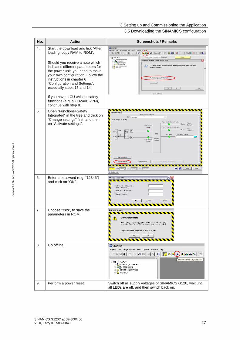
No. Action Screenshots / Remarks
4. Start the download and tick “After loading, copy RAM to ROM”. Should you receive a note which indicates different parameters for the power unit, you need to make your own configuration. Follow the instructions in chapter 6 “Configuration and Settings”, especially steps 13 and 14. If you have a CU without safety functions (e.g. a CU240B-2PN), continue with step 8.
5. Open “Functions>Safety Integrated” in the tree and click on “Change settings” first, and then on “Activate settings”.
6. Enter a password (e.g. “12345”) and click on “OK”.
7. Choose “Yes”, to save the parameters in ROM.
8. Go offline.
9. Perform a power reset. Switch off all supply voltages of SINAMICS G120, wait until all LEDs are off, and then switch back on.

4 Operation of the Application
4.1 Prerequisites
28 SINAMICS G120C at S7-300/400
V2.0, Entry ID: 58820849
Co
pyr
igh
t
Sie
me
ns
AG
20
12
All
righ
ts r
ese
rve
d
4 Operation of the Application
4.1 Prerequisites
To be able to switch on the SINAMICS G120 via the S7-300/400 inputs, the following points must be fulfilled:
• If the safety functions of the SINAMICS G120 has been activated, then 24V must be supplied at terminals 16 and 17 (DI 4 and 5) of the SINAMICS G120; otherwise, the STO safety function is active, the yellow “SAFE” LED at the SINAMICS G120 is blinking and the SINAMICS G120 cannot be switched on. For the SINAMICS G120D, these are terminals X9.2 and X9.4 .
• 24V must not be supplied at terminal 8 (DI 3) of the SINAMICS G120, otherwise the command data record is switched over (at standard configuration). For SINAMICS G120D this is terminal X8.2.
• When using an IOP, please check that the network icon ( ) is displayed on the top right. If the hand icon ( ) is displayed there, press the Hand/Auto button ( ).
• When using a BOP-2, please check whether the hand icon ( ) is displayed. If yes, press the Hand/Auto button ( ).
4.2 Operation of the Application
SINAMICS G120 is exclusively moved via digital inputs. The HMI is then only used for monitoring.
Table 4-1
Terminal Name Function
E 0.0 ON Switching SINAMICS G120 on/off, (Off2 and Off3 =1 must apply for the operation)
E 0.1 OFF2 0= Motor immediately switched off, drive spins out
E 0.2 OFF3 0= Fast stop, motor is decelerated with Off3 ramp down time (P1135) until it stops
E 0.3 Ack Rising edge acknowledges a pending error in the SINAMICS G120
E 0.4 Rev Reversed direction, the polarity of the setpoint value is negated
E 0.5 0 The setpoint value is set to 0.
E 0.6 n+ The setpoint value is increased
E 0.7 n- The setpoint value is decreased

4 Operation of the Application
4.2 Operation of the Application
SINAMICS G120C at S7-300/400 V2.0, Entry ID: 58820849 29
Co
pyr
igh
t
Sie
me
ns
AG
20
12
All
righ
ts r
ese
rve
d
To switch on SINAMICS G120, please perform the steps below:
Table 4-2
Step Action Note / Result
1. Apply 24V to OFF2(E0.1) and OFF3(E0.2).
The further required control bits for the operation are permanently set to 1 by the program.
2. Enter a pulse (switching on and back off) to Ack (E0.3).
This acknowledges a possibly pending error message.
3. Enter a pulse (switching on and back off) to 0 (E0.5).
The setpoint is set to 0.
4. Apply 24V to ON(E0.0). The drive switches on.
5. Change the setpoint value with inputs n+ (E 0.6), n- (E0.7) and 0 (E0.5).
The speed of the motor changes.
6. Detach the 24V from ON(E0.0). The drive switches back off.

4 Operation of the Application
4.3 Monitoring and parameter access via operator panel
30 SINAMICS G120C at S7-300/400
V2.0, Entry ID: 58820849
Co
pyr
igh
t
Sie
me
ns
AG
20
12
All
righ
ts r
ese
rve
d
4.3 Monitoring and parameter access via operator panel
4.3.1 Screens and screen navigation
Figure 4-1
Example project Support
Process data exchange Parameter access
From all subordinatescreens
From all subordinatescreens
Sta
rt s
cree
n
Ov
erv
iew
scre
en
On
line
Su
pp
ort
-P
rom
oti
on
Sta
tus
an
d c
on
tro
lw
ord
Set
po
int
an
d a
ctu
alv
alu
es
RE
ad/
wri
tep
ara
met
ers
Fau
lt b
uff
er
Terminate Runtime
Switch language (German/English)

4 Operation of the Application
4.3 Monitoring and parameter access via operator panel
SINAMICS G120C at S7-300/400 V2.0, Entry ID: 58820849 31
Co
pyr
igh
t
Sie
me
ns
AG
20
12
All
righ
ts r
ese
rve
d
4.3.2 Process data exchange
Both screens for the process data exchange access the idb_Process_Data data block (DB11).
Control and status word
Figure 4-2
The bit commands, which you can partially specify via the digital input module, are displayed in the 16 bit wide control word.
The current state of the SINAMICS G120 is given via the also 16 bit wide status word.
Manual mode
Using the “Manual mode” button enables activating the manual mode of the block. Instead of switching to the control signals pending at the block, in this example to the digital inputs, this mode switches to an internal control word specified via HMI, for example. Also, an internal value is used instead of the pending setpoint value.
This enables a simple manual/automatic switch-over.
DANGER
When (de-)activating the manual mode, the control word and the setpoint value are not adjusted. It is therefore possible when switching over that SINAMICS G120 automatically starts up or changes the speed.
In this example, this enables switching from the digital inputs to manual operation via HMI. The set control word bits are then displayed yellow.

4 Operation of the Application
4.3 Monitoring and parameter access via operator panel
32 SINAMICS G120C at S7-300/400
V2.0, Entry ID: 58820849
Co
pyr
igh
t
Sie
me
ns
AG
20
12
All
righ
ts r
ese
rve
d
Setpoint and actual values
Figure 4-3
Setpoint speed value: Here, the setpoint speed value is displayed which in this example, is set via the digital inputs E0.4 to E0.7 (see Table 4-1). In manual mode, the speed setpoint value is directly specified via HMI, the input field is then shaded yellow.
DANGER
When (de-)activating the manual mode, the control word and the setpoint value are not adjusted. It is therefore possible when switching over that SINAMICS G120 automatically starts up or changes the speed.
Actual values: The current actual values for speed, electrical current and torque are displayed below the speed setpoint value input.
Control and status word: To keep an eye on control word and status word, without switching to the respective screen, they are also given here as a miniature display.
4 Operation of the Application
4.3 Monitoring and parameter access via operator panel
SINAMICS G120C at S7-300/400 V2.0, Entry ID: 58820849 33
Co
pyr
igh
t
Sie
me
ns
AG
20
12
All
righ
ts r
ese
rve
d
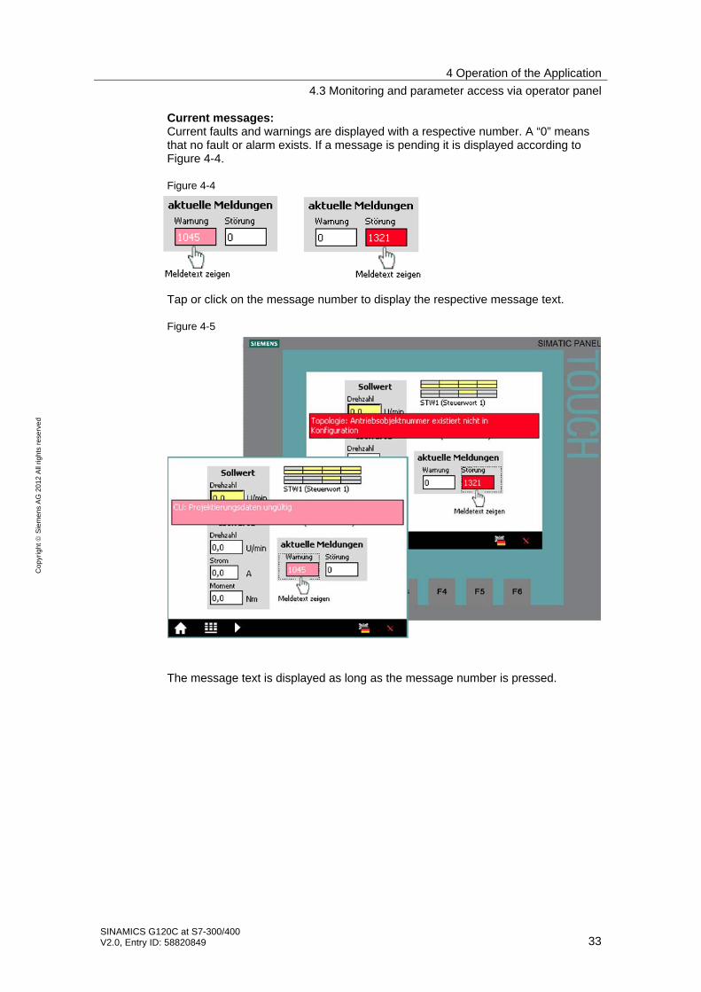
Current messages: Current faults and warnings are displayed with a respective number. A “0” means that no fault or alarm exists. If a message is pending it is displayed according to Figure 4-4.
Figure 4-4
Tap or click on the message number to display the respective message text.
Figure 4-5
The message text is displayed as long as the message number is pressed.

4 Operation of the Application
4.3 Monitoring and parameter access via operator panel
34 SINAMICS G120C at S7-300/400
V2.0, Entry ID: 58820849
Co
pyr
igh
t
Sie
me
ns
AG
20
12
All
righ
ts r
ese
rve
d
4.3.3 Parameter access
Both screens for the process data exchange access the idb_Parameter_Access data block (DB11).
Reading/writing parameters
Figure 4-6

4 Operation of the Application
4.3 Monitoring and parameter access via operator panel
SINAMICS G120C at S7-300/400 V2.0, Entry ID: 58820849 35
Co
pyr
igh
t
Sie
me
ns
AG
20
12
All
righ
ts r
ese
rve
d
Table 4-3
Action Comment
1. Select the access type with the “Read parameters” and “Write parameters” buttons.
The selected access type is displayed via a bright green button.
2. Read parameters: Proceed with point 3 in the table. Write parameters: When tapping or clicking the yellow input field for the rampup/rampdown time, a keyboard mask for the value input opens. Close your input with the Return key.
8,0
3. Start the write or read job with the “Start” button.
The job status specifies how the job was completed:
done = completed without error
errori = job cancelled with error The status refers to processing the system function blocks SFB 52 “RDREC” and SFB 53 “WRREC” in STEP7 code. For error diagnosis see /3/.
done and drive_errori means that the job was transferred without error, however, SINAMICS G120 could not or only partially process the job. The error codes are available in chapter 6.1.5.1 “Configuring the fieldbus, PROFIdrive profile for PROFIBUS and PROFINET, acyclic communication” in the operating instruction (/7/).
4. Click “Start” again to terminate the transmission requirement.
The bits of the job status are deleted as soon as the transmission requirement is no longer pending.
Note If you wish to check the parameters after a write job, you must trigger an additional read job.

4 Operation of the Application
4.3 Monitoring and parameter access via operator panel
36 SINAMICS G120C at S7-300/400
V2.0, Entry ID: 58820849
Co
pyr
igh
t
Sie
me
ns
AG
20
12
All
righ
ts r
ese
rve
d
Fault buffer
The screen displays the fault codes of eight current and eight acknowledged faults, which are saved in the SINAMICS G120.
Note The values are read by SINAMICS G120 via the “Read parameters” function in Figure 4-6 and saved in the S7-300/400.
When the “Fault buffer” screen comes up, the data stored in S7300/400 is displayed and may therefore be out of date.
Figure 4-7
Tap or click on the message number to display the respective message text.
Figure 4-8
The message text is displayed as long as the message number is pressed.
5 Functional Mechanisms of the Application
4.3 Monitoring and parameter access via operator panel
SINAMICS G120C at S7-300/400 V2.0, Entry ID: 58820849 37
Co
pyr
igh
t
Sie
me
ns
AG
20
12
All
righ
ts r
ese
rve
d
5 Functional Mechanisms of the Application
Program overview
Figure 5-1
SFB 52 “RDREC“
OB 1 “CYCL_EXC“
FC 5 “setpoint_simulation“
FB 20 “parameteraccess“
DB 20 “idb parameter access“
SFB 53 “WRREC“
DB 100 “write driveparameter“
FB 10 “process data“
DB 10 “idb process data“
DB 102 “answerfrom drive_write“
DB 101 “read driveparameter“
DB 103 “answerfrom drive_read“
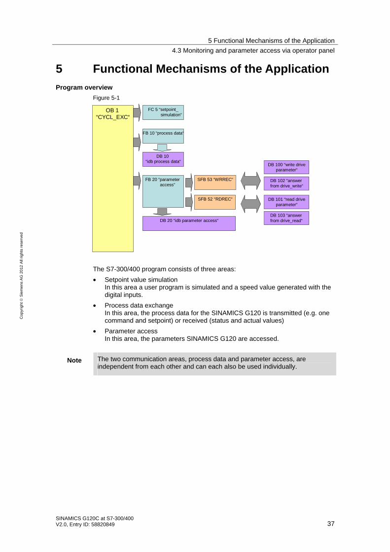
The S7-300/400 program consists of three areas:
• Setpoint value simulation In this area a user program is simulated and a speed value generated with the digital inputs.
• Process data exchange In this area, the process data for the SINAMICS G120 is transmitted (e.g. one command and setpoint) or received (status and actual values)
• Parameter access In this area, the parameters SINAMICS G120 are accessed.
Note The two communication areas, process data and parameter access, are independent from each other and can each also be used individually.

5 Functional Mechanisms of the Application
5.1 Functionality of process data exchange
38 SINAMICS G120C at S7-300/400
V2.0, Entry ID: 58820849
Co
pyr
igh
t
Sie
me
ns
AG
20
12
All
righ
ts r
ese
rve
d
5.1 Functionality of process data exchange
Figure 5-2
SFB 52 “RDREC“
OB 1 “CYCL_EXC“
FC 5 “setpoint_simulation“
FB 20 “parameteraccess“
DB 20 “idb parameter access“
SFB 53 “WRREC“
DB 100 “write driveparameter“
FB 10 “process data“
DB 10 “idb process data“
DB 102 “answerfrom drive_write“
DB 101 “read driveparameter“
DB 103 “answerfrom drive_read“
The process data contains values which are regularly exchanged between S7-300/400 and SINAMICS G120. These values are at least the control and status word as well as the setpoint and actual value. Selecting the message frame type specifies the exact length and structure.
The “Siemens Telegram 352, PZD 6/6” message frame type used in the example exchanges 6 words in both directions, which are:
Table 5-1 Structure of Siemens “Telegram 352, PZD 6/6”
Send direction (viewed from SIMATIC) Receive direction (viewed from SIMATIC)
Control word Status word
Setpoint speed value Current speed (actual speed value)
(not used) Current electrical current
(not used) Current torque
(not used) Current warning
(not used) Current fault

5 Functional Mechanisms of the Application
5.1 Functionality of process data exchange
SINAMICS G120C at S7-300/400 V2.0, Entry ID: 58820849 39
Co
pyr
igh
t
Sie
me
ns
AG
20
12
All
righ
ts r
ese
rve
d
5.1.1 Accessing process data in the user program of the S7-300/400
At the start of the cycle, the operating system of S7-300/400 stores the (user) data received by the SINAMICS G120 in the I/O input area of the CPU and transmits the data stored in the I/O output area to the SINAMICS G120 at the end of the cycle. In the user program, the data can be accessed by reading from or writing to the I/O area. The address areas used are defined when specifying the hardware configuration. See step 15 in Table 6-1. If the I/O is accessed with the SFC 14/15 system functions, the consistency is ensured across the entire data; hence, these functions are used in the example program.
5.1.2 Standardizing the setpoint and actual values
The setpoint and actual values are transferred as standards. The reference values are stored in parameters P2000 to P2006 of the SINAMICS G120.
FB20 “Parameter_Access” takes on entirely the conversion of setpoint and actual values. The reference values for speed current, torque stored in parameters P2000, P2003 and P2004 of SINAMICS must also be entered at the block input.
16384dec = 4000hex = 100% applies here, with 100% referring to the reference value for the transferred variable.
Example:
If P2000 (reference speed or reference frequency) is 1500 1/min and if a speed of 500 1/min shall be run, then 33% or 5461dec must be transferred.
5 Functional Mechanisms of the Application
5.1 Functionality of process data exchange
40 SINAMICS G120C at S7-300/400
V2.0, Entry ID: 58820849
Co
pyr
igh
t
Sie
me
ns
AG
20
12
All
righ
ts r
ese
rve
d
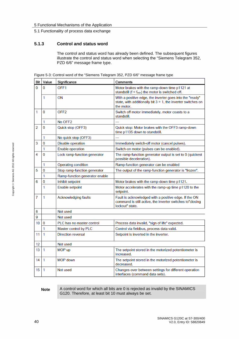
5.1.3 Control and status word
The control and status word has already been defined. The subsequent figures illustrate the control and status word when selecting the “Siemens Telegram 352, PZD 6/6” message frame type.
Figure 5-3: Control word of the “Siemens Telegram 352, PZD 6/6” message frame type
Note A control word for which all bits are 0 is rejected as invalid by the SINAMICS G120. Therefore, at least bit 10 must always be set.

5 Functional Mechanisms of the Application
5.1 Functionality of process data exchange
SINAMICS G120C at S7-300/400 V2.0, Entry ID: 58820849 41
Co
pyr
igh
t
Sie
me
ns
AG
20
12
All
righ
ts r
ese
rve
d
Figure 5-4 Status word of the “Siemens Telegram 352, PZD 6/6” message frame type
5 Functional Mechanisms of the Application
5.1 Functionality of process data exchange
42 SINAMICS G120C at S7-300/400
V2.0, Entry ID: 58820849
Co
pyr
igh
t
Sie
me
ns
AG
20
12
All
righ
ts r
ese
rve
d
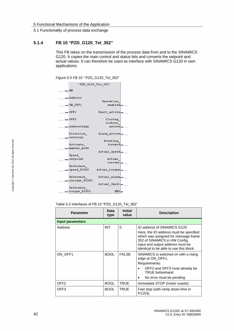
5.1.4 FB 10 “PZD_G120_Tel_352”
This FB takes on the transmission of the process data from and to the SINAMICS G120. It copies the main control and status bits and converts the setpoint and actual values. It can therefore be used as interface with SINAMICS G120 in own applications.
Figure 5-5 FB 10 “ PZD_G120_Tel_352“
Table 5-2 Interfaces of FB 10 “PZD_G120_Tel_352”
Parameter Data type
Initial value
Description
Input parameters
Address INT 0 IO address of SINAMICS G120 Here, the IO address must be specified which was assigned for message frame 352 of SINAMICS in HW Config. Input and output address must be identical to be able to use this block.
ON_OFF1 BOOL FALSE SINAMICS is switched on with a rising edge at ON_OFF1. Requirements:
• OFF2 and OFF3 must already be TRUE beforehand
• No error must be pending
OFF2 BOOL TRUE Immediate STOP (motor coasts)
OFF3 BOOL TRUE Fast stop (with ramp down time in P1153)
5 Functional Mechanisms of the Application
5.1 Functionality of process data exchange
SINAMICS G120C at S7-300/400 V2.0, Entry ID: 58820849 43
Co
pyr
igh
t
Sie
me
ns
AG
20
12
All
righ
ts r
ese
rve
d
Parameter Data type
Initial value
Description
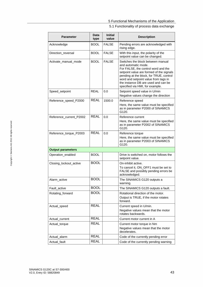
Acknowledge BOOL FALSE Pending errors are acknowledged with rising edge.
Direction_reversal BOOL FALSE With this input, the polarity of the setpoint value can be changed.
Activate_manual_mode BOOL FALSE Switches the block between manual and automatic mode. For FALSE, the control word and the setpoint value are formed of the signals pending at the block, for TRUE, control word and setpoint value from tags in the instance DB are used and can be specified via HMI, for example.
Speed_setpoint REAL 0.0 Setpoint speed value in U/min Negative values change the direction
Reference_speed_P2000 REAL 1500.0 Reference speed Here, the same value must be specified as in parameter P2000 of SINAMICS G120.
Reference_current_P2002 REAL 0.0 Reference current Here, the same value must be specified as in parameter P2002 of SINAMICS G120.
Reference_torque_P2003 REAL 0.0 Reference torque Here, the same value must be specified as in parameter P2003 of SINAMICS G120.
Output parameters
Operation_enabled BOOL Drive is switched on, motor follows the setpoint value.
Closing_lockout_active BOOL On-inhibit active. To cancel it, ON_OFF1 must be set to FALSE and possibly pending errors be acknowledged.
Alarm_active BOOL The SINAMICS G120 outputs a warning.
Fault_active BOOL The SINAMICS G120 outputs a fault.
Rotating_forward BOOL Rotational direction of the motor. Output is TRUE, if the motor rotates forward.
Actual_speed REAL Current speed in U/min. Negative values mean that the motor rotates backwards.
Actual_current REAL Current motor current in A
Actual_torque REAL Current motor torque in Nm Negative values mean that the motor decelerates.
Actual_alarm REAL Code of the currently pending error
Actual_fault REAL Code of the currently pending warning
5 Functional Mechanisms of the Application
5.1 Functionality of process data exchange
44 SINAMICS G120C at S7-300/400
V2.0, Entry ID: 58820849
Co
pyr
igh
t
Sie
me
ns
AG
20
12
All
righ
ts r
ese
rve
d
NOTICE To switch on SINAMICS G120, OFF2 and OFF3 must initially be TRUE, then SINAMICS G120 can be switched on with a positive edge (i.e. the signal changes from FALSE to TRUE) at ON/OFF1.
Manual/automatic switchover (manual mode)
This function enables selecting whether SINAMICS G120 shall be controlled with the values pending at the block inputs, or whether internal values shall be used and the block inputs be ignored. The internal values are located in the instance DB (“internal_Control_word” and “internal_Status_word”) and can be specified by a visualization.
This enables realizing a switch-over between the values supplied by SIMATIC S7 (automatic) and the specification via a visualization (manual).
Independent of these settings, the bits of the status word and the actual values are always output.
DANGER
When switching over (activating or deactivating the manual mode), the control word and the setpoint value are not adjusted. It is therefore possible when switching over that SINAMICS G120 automatically starts up or changes the speed.
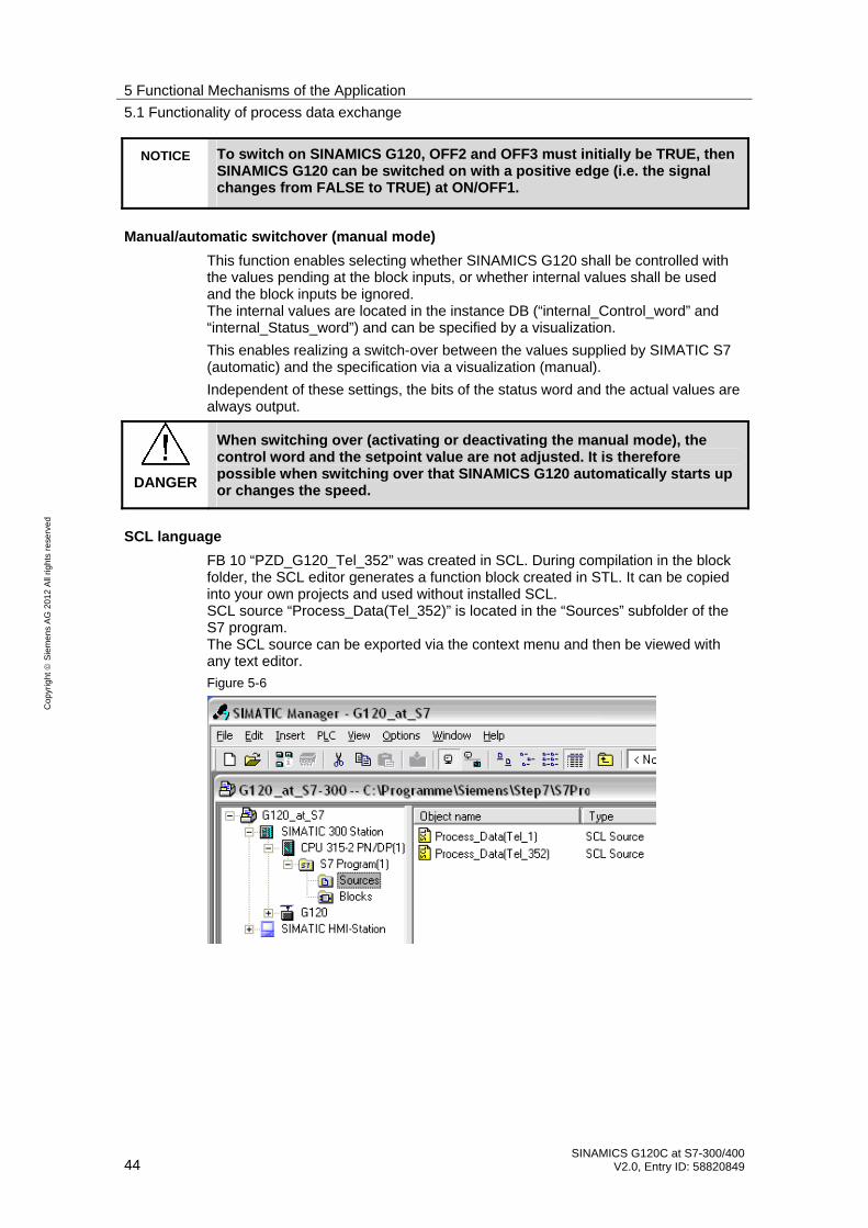
SCL language
FB 10 “PZD_G120_Tel_352” was created in SCL. During compilation in the block folder, the SCL editor generates a function block created in STL. It can be copied into your own projects and used without installed SCL. SCL source “Process_Data(Tel_352)” is located in the “Sources” subfolder of the S7 program. The SCL source can be exported via the context menu and then be viewed with any text editor.
Figure 5-6

5 Functional Mechanisms of the Application
5.2 Change-over to “Siemens Telegram 1” (with FB11)
SINAMICS G120C at S7-300/400 V2.0, Entry ID: 58820849 45
Co
pyr
igh
t
Sie
me
ns
AG
20
12
All
righ
ts r
ese
rve
d
5.2 Change-over to “Siemens Telegram 1” (with FB11)
FB11 “PZD_G120_Tel_1” is, like FB10 “PZD_G120_Tel_352”, intended for transmission of process data, however, it expects message frame “Siemens Telegram 1” instead of “Siemens Telegram 352”.
The “Telegram 1” message frame only transfers two words in any direction: control word and setpoint value or status word and actual value.
Figure 5-7
To switch over to message frame “Telegram 1”, you have to:
• select message frame “Telegram 1” for SINAMICS G120 in HW Config,
• call FB11“ PZD_G120_Tel_1” in OB1 instead of FB10 “PZD_G120_Tel_352”,
• load the program folder into the CPU again (inc. system data, see Tab. 3.4 step 9),
• change the interface configuration of SINAMICS G120 to message frame “Telegram 1” in the Starter, see Tab. 6.2 step 15) and
• adjust the HMI.

5 Functional Mechanisms of the Application
5.3 Parameter access functionality
46 SINAMICS G120C at S7-300/400
V2.0, Entry ID: 58820849
Co
pyr
igh
t
Sie
me
ns
AG
20
12
All
righ
ts r
ese
rve
d
5.3 Parameter access functionality
Figure 5-8
SFB 52 “RDREC“
OB 1 “CYCL_EXC“
FC 5 “setpoint_simulation“
FB 20 “parameteraccess“
DB 20 “idb parameter access“
SFB 53 “WRREC“
DB 100 “write driveparameter“
FB 10 “process data“
DB 10 “idb process data“
DB 102 “answerfrom drive_write“
DB 101 “read driveparameter“
DB 103 “answerfrom drive_read“
Acyclic parameter access occurs parallel to the cyclic process data exchange. This saves resources, since this connection is only established on demand, i.e. when accessing a parameter.
In S7-300/400, the “Write data record” and “Read data record” functions must be used. Data record 47 must always be used.
Writing data record 47 sends a job to the SINAMICS G120 which performs the job and provides a response. Reading data record 47 makes the response of SINAMICS G120 available in S7-300/400 and can be evaluated.
For reading and writing data records, the system function blocks SFB 53 “WRREC” and SFB 52 “RDREC” are used in S7-300/400.
The structure of data record 47 is available in chapter chapter 6.1.5.1 “Configuring the fieldbus, PROFIdrive profile for PROFIBUS and PROFINET, acyclic communication” in the operating instruction (/7/)
Note Since SFB 53 “WRREC” and SFB 52 “RDREC” are not used with CP341-1, the parameter access is not possible when using this CP.

5 Functional Mechanisms of the Application
5.3 Parameter access functionality
SINAMICS G120C at S7-300/400 V2.0, Entry ID: 58820849 47
Co
pyr
igh
t
Sie
me
ns
AG
20
12
All
righ
ts r
ese
rve
d
5.3.1 FB 20 “Parameter_Access”
The parameters are accessed in FB 20 “Parameter_Access”. It is called cyclically in OB 1. The block was created so they can simply be used in own applications.
Figure 5-9
Table 5-3 Interfaces of FB 20 “Parameter_Access”
Parameter Data type
Initial value
Description
Input parameters
Address INT 0 IO address of SINAMICS G120. Here, the IO address must be specified which was assigned for message frame Telegram 352 of SINAMICS in HW Config. Input and output address must be identical to be able to use this block.
DB_No_send INT 0 Number of the DB in which the data record to be sent is stored.
DB_No_rev INT 0 Number of the DB in which the response of SINAMICS G120 is to be stored.
START BOOL FALSE The transmission is started with a rising edge at START.
Output parameters
Busy BOOL Transmission active
Done BOOL Job successfully transferred.
Drive_Error BOOL Job successfully transferred, however, the job could not or only partially be completed by SINAMICS G120. The response contains the error detection.
Error BOOL Access aborted with transmission error
ErrorID WORD Cause of the abort (see subsequent error list)

5 Functional Mechanisms of the Application
5.3 Parameter access functionality
48 SINAMICS G120C at S7-300/400
V2.0, Entry ID: 58820849
Co
pyr
igh
t
Sie
me
ns
AG
20
12
All
righ
ts r
ese
rve
d
Error list
The FB 20 “Parameter_Access” can output the following error codes:
Table 5-4
Error number Description Note
0 No error
8000 DB_No_send and DB_No_rev are identical.
8001 DB_No_rev or DB_No_send is zero.
Check the parameters of FB 20 “Parameter_Access”.
8002 SFC53 “WEREC” outputs errors
In the instance DB, the error code of the SFC is stored in #WD_REC_STATUS.
8003 SFC53 “WEREC” outputs errors
In the instance DB, the error code of the SFC is stored in #RD_REC_STATUS.
8004 Send DB is empty (length 0), non existent or faulty.
In the instance DB, the error code of the SFC24 “TEST_DB” is stored in #TEST_DB_1_STATUS. If the code is 0, the DB is empty or write protected.
8005 Receive DB is empty (length 0), non existent or faulty.
In the instance DB, the error code of the SFC24 “TEST_DB” is stored in #TEST_DB_2_STATUS. If the code is 0, the DB is empty or write protected.
Drive error
If during processing a job in SINAMICS G120 an error occurred, and the error detection was set in the response, the response DB must be analyzed to find out the cause of the error.
Function
FB 20 “Parameter_Accesss” only transfers the selected DBs to or from SINAMICS G120 and checks, whether the transmission was successful. It is also checked, whether the error detection was set in the response of the SINAMICS G120.
The structure of the error detection is available in chapter chapter 6.1.5.1 “Configuring the fieldbus, PROFIdrive profile for PROFIBUS and PROFINET, acyclic communication” in the operating instruction (/7/)
Structure
The “Parameter” FB consists of three parts:
• Checking the DB_No_xx input parameters Network 1
• A step chain which controls the sequence of the parameter access. Networks 2 to 10
• Call of the system functions “Read data record” or “Write data record”. Network 11

5 Functional Mechanisms of the Application
5.3 Parameter access functionality
SINAMICS G120C at S7-300/400 V2.0, Entry ID: 58820849 49
Co
pyr
igh
t
Sie
me
ns
AG
20
12
All
righ
ts r
ese
rve
d
Checking the DB_No_xx input parameters
It is checked, whether input parameters DB_No_send and DB_No_rev are equal or if they were parameterized with “0”. One respective error message is output.
Note Network 1 with checking the DB_No_xx input parameters can be deleted to save computing time and storage space without affecting the other functions of the block.
Step chain
The step chain of FB 20 “Parameter_access” is represented in the following graphic. The possible transitions between the individual steps are also displayed there.
Figure 5-10 Step chain

5 Functional Mechanisms of the Application
5.3 Parameter access functionality
50 SINAMICS G120C at S7-300/400
V2.0, Entry ID: 58820849
Co
pyr
igh
t
Sie
me
ns
AG
20
12
All
righ
ts r
ese
rve
d
In the individual states of the step chain, the following functions are executed:
Table 5-5: Function of the states of FB 20 “Parameter_access”
State Function
0 Wait for start trigger Waiting for a rising edge of the “START” signal. If it is detected, all output signals will be deleted, “BUSY” will be set and step 1 will be activated.
1 Start WR_REC The “REQ” signal of SFB 53 “WRREC” is set and step 2 is activated.
2 Wait for end of WR_REC
Waiting until the “busy” signal of SFB 53 “WRREC” becomes 0 again. Then step 3 is activated.
3 Check result of WR_REC
It is checked whether the data record was written successfully. If so, the “REQ” signal of SFB 53 “WRREC” will be deleted again and step 4 will be activated. If SFB 53 “WRREC” reports the error 16#DF80_B500 (peer not ready), step 3 will be activated again and SFB 53 “WRREC” will repeat the job. If a different error has occurred, the “REQ” signal of SFB 53 “WRREC” will be deleted, an internal error bit will be set and step 7 will be activated.
4 Start RD_REC The “REQ” signal of FB “RDREC” is set and step 5 is activated.
5 Wait for end of RD_REC
It is waited until the “busy” signal of FB “RDREC” becomes 0 again. Then step 6 is activated.
6 Check result of RD_REC
Check whether the data record has been read successfully. If so, the “REQ” signal of SFB 52 “RDREC” will be deleted again and step 7 will be activated. If SFB 52 “RDREC” reports the error 16#DE80_B500 (peer not ready), step 5 will be activated again and FB “RDREC” will repeat the job. If a different error has occurred, the “REQ” signal of SFB 52 “RDREC” will be deleted, an internal error bit will be set and step 7 will be activated.
7 Check for errors, copy outputs
It is checked whether one of the internal error bits has been set. If an error bit has been set,
– the “ERROR” signal will be set, – the “BUSY” signal deleted, – step 0 activated.
If no error bit has been set, the read times will be output, the “BUSY” will be deleted, the “DONE” will be set and step 0 will be activated.
Call of the “Read data record” or “Write data record” system functions
After the currently required control bits were set in the sequence chart of FB 20 “Parameter_access”, the “Write data record” and “Read data record” system functions (SFB 53 “WRREC” and SFB 52 “RDREC”) are called in network 10.
It is initially checked, whether the DB to be used exists in the S7-CPU and how long it is. This creates an ANY pointer which references the data to be send/received and calls the SFC.

5 Functional Mechanisms of the Application
5.3 Parameter access functionality
SINAMICS G120C at S7-300/400 V2.0, Entry ID: 58820849 51
Co
pyr
igh
t
Sie
me
ns
AG
20
12
All
righ
ts r
ese
rve
d
5.3.2 The DBs “read/write_drive_parameters” and “answer_from_drive”
To access the parameters, a given job structure must be kept. The response of SINAMICS G120 also contains a given response structure.
Job and response structure
The structure of the jobs and responses are available in Chapter 7.3.2.1 “Configuring the fieldbus, PROFIdrive profile for PROFIBUS and PROFINET, acyclic communication” in the operating instruction (/7/)
Note Since the structure of the data record to be sent or received depends on the number of jobs and their number format, a generally valid structure cannot be used.
FB 20 “Parameter_Access” is therefore limited to sending and receiving the data record. The DBs for the data record to be send and received must be set by the user.
The job to access a parameter consists of at least 10 words. Therefore, the job should be assembled in a DB. The response by the SINAMICS G120 also consists of several words.
A job may contain the access to several parameters. Since the length of the data to be transferred per job depends on the number and data types of the SINAMICS G120 parameters, no generally valid structure can be devised.
In this example, only the ramp up and ramp down times (P1120 and P1121) and a part of the fault memory (P945.x) is accessed. The job of writing the parameters is stored in DB 100 “write_drive_parameters” and the job to read the parameters in DB 101 “read_drive_parameters”.
The response of the SINAMICS G120 is copied to DB 102 “answer_from_drive_ write” or DB 103 “answer_from_drive_write_read”. The structure contained therein corresponds to the structure for a successful writing/reading of the parameters.

5 Functional Mechanisms of the Application
5.3 Parameter access functionality
52 SINAMICS G120C at S7-300/400
V2.0, Entry ID: 58820849
Co
pyr
igh
t
Sie
me
ns
AG
20
12
All
righ
ts r
ese
rve
d
Figure 5-11 DB 100 for writing the ramp up and ramp down time (in the picture: 10s and 15 s)
Figure 5-12 DB 102 for the response to the write job

5 Functional Mechanisms of the Application
5.3 Parameter access functionality
SINAMICS G120C at S7-300/400 V2.0, Entry ID: 58820849 53
Co
pyr
igh
t
Sie
me
ns
AG
20
12
All
righ
ts r
ese
rve
d
Figure 5-13 DB 101 for reading the ramp up and ramp down time and 16 values of the fault memory
Figure 5-14: DB 103 for the response of the read job
Note Since the structure of the data record to be sent or received depends on the number of jobs and their number format, a generally valid structure cannot be used.

5 Functional Mechanisms of the Application
5.4 Function of the further blocks in the example projects
54 SINAMICS G120C at S7-300/400
V2.0, Entry ID: 58820849
Co
pyr
igh
t
Sie
me
ns
AG
20
12
All
righ
ts r
ese
rve
d
5.4 Function of the further blocks in the example projects
Apart from FB10 and FB20 further blocks are contained in the example projects which are necessary to make the examples runnable.
These tables are:
Table 5-6
Block Function
OB86 If the connection to a PROFIBUS station is interrupted or restored, the S7-CPU calls these error organization blocks. If this OB does not exist in the S7-CPU, it goes to STOP instead.In this OB, the user can program a reaction to a failed or restored station, in this example it is empty.
FC5 Function for generating a speed setpoint value using the digital inputs. The setpoint value is stored in MD0. This block is not intended for use in your own projects.
VAT_Process_Data
VAT_Parameter_Access
Value tables for monitoring and control of FB10 and FB20.
6 Configuration and Settings
6.1 Configuring the S7-300/400 controller
SINAMICS G120C at S7-300/400 V2.0, Entry ID: 58820849 55
Co
pyr
igh
t
Sie
me
ns
AG
20
12
All
righ
ts r
ese
rve
d
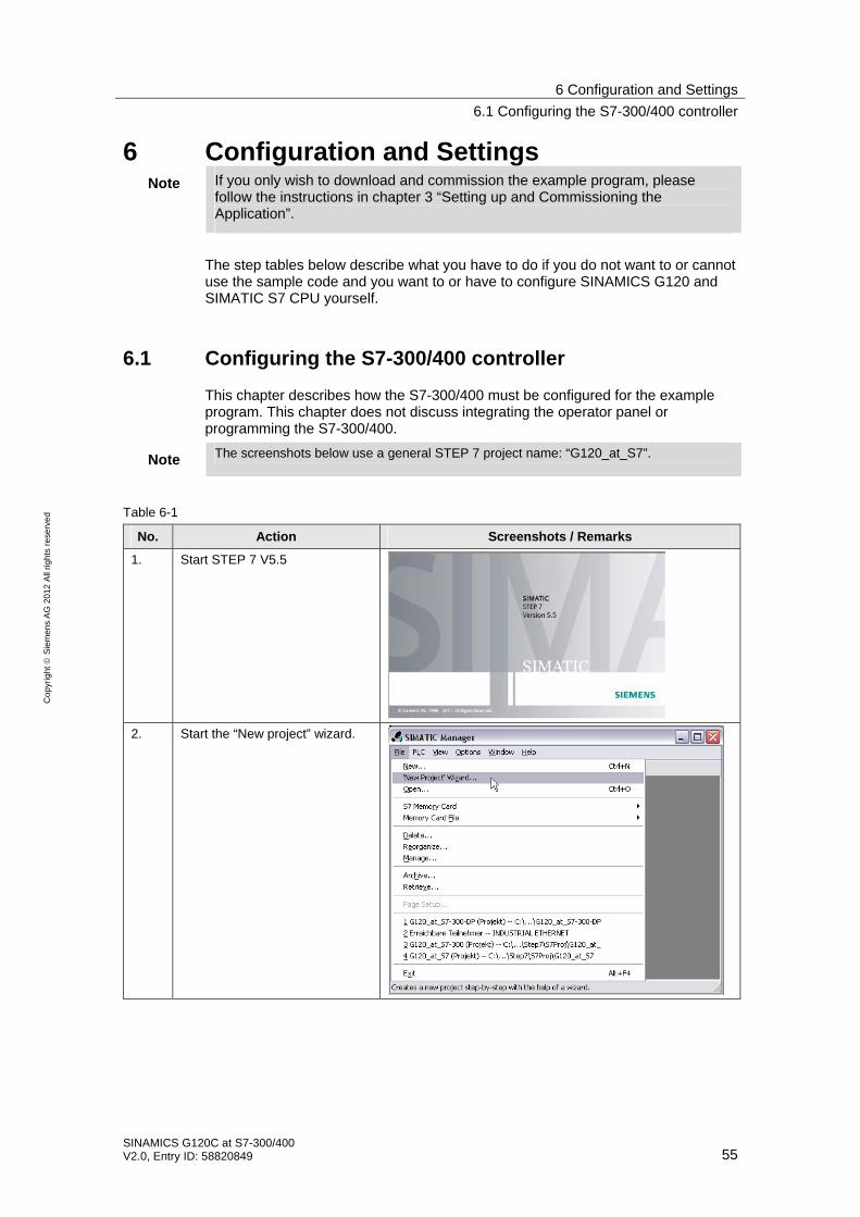
6 Configuration and Settings Note If you only wish to download and commission the example program, please
follow the instructions in chapter 3 “Setting up and Commissioning the Application”.
The step tables below describe what you have to do if you do not want to or cannot use the sample code and you want to or have to configure SINAMICS G120 and SIMATIC S7 CPU yourself.
6.1 Configuring the S7-300/400 controller
This chapter describes how the S7-300/400 must be configured for the example program. This chapter does not discuss integrating the operator panel or programming the S7-300/400.
Note The screenshots below use a general STEP 7 project name: “G120_at_S7”.
Table 6-1
No. Action Screenshots / Remarks
1. Start STEP 7 V5.5
2. Start the “New project” wizard.

6 Configuration and Settings
6.1 Configuring the S7-300/400 controller
56 SINAMICS G120C at S7-300/400
V2.0, Entry ID: 58820849
Co
pyr
igh
t
Sie
me
ns
AG
20
12
All
righ
ts r
ese
rve
d
No. Action Screenshots / Remarks
3. Select CPU 315-2DP/PN, or another CPU, which supports data record routing, see /9/.
4. In this screen you click “Continue >”.
5. Assign a name for the project (e.g. “G120_at_S7-300”).

6 Configuration and Settings
6.1 Configuring the S7-300/400 controller
SINAMICS G120C at S7-300/400 V2.0, Entry ID: 58820849 57
Co
pyr
igh
t
Sie
me
ns
AG
20
12
All
righ
ts r
ese
rve
d
No. Action Screenshots / Remarks
6. • Click on the S7-300 station
• Double-click the “Hardware” icon to open the hardware configuration.
7. Select the PROFINET interface of the CPU and choose “Insert PROFINET IO System“ from the context menu (right mouse button)
8. • Ensure that address 192.168.0.1 and network mask 255.255.225.000 have been assigned.
• Click on the “New” button and create an Ethernet network. The CPU will automatically be connected to it.
• Click OK
• Click on OK in the higher-level mask

6 Configuration and Settings
6.1 Configuring the S7-300/400 controller
58 SINAMICS G120C at S7-300/400
V2.0, Entry ID: 58820849
Co
pyr
igh
t
Sie
me
ns
AG
20
12
All
righ
ts r
ese
rve
d
No. Action Screenshots / Remarks
9. Double-click on the PN/IO interface of the CPU.
10. Change the device name to “S7-CPU” (or the respective name assigned during node initiation (step 4 in Table 3-3) ).
11. Ensure that the PROFINET network is displayed.

6 Configuration and Settings
6.1 Configuring the S7-300/400 controller
SINAMICS G120C at S7-300/400 V2.0, Entry ID: 58820849 59
Co
pyr
igh
t
Sie
me
ns
AG
20
12
All
righ
ts r
ese
rve
d
No. Action Screenshots / Remarks
12. • Search your SINAMICS G120 in the catalog: The path in the catalog is: > PROFINET IO > Drives > SINAMICS > SINAMICS G120x
• Then select your CU (Control Unit). Depending on which SINAMICS G120 you have, you must use one of the following entries: SINAMICS G120: – G120 CU240E-2 PN
– G120 CU230B-2 PN F
SINAMICS G120C: – G120C PN
SINAMICS G120D: – G120D CU 240D-2 PN
– G120D CU 240D-2 PN F
– G120D CU 250D-2 PN F
• SINAMICS G120P: – G120 CU230P-2 PN (in the SINAMICS G120 folder)
The picture shows the example of a selected SINAMICS G120 with CU 240E-2 PN.

6 Configuration and Settings
6.1 Configuring the S7-300/400 controller
60 SINAMICS G120C at S7-300/400
V2.0, Entry ID: 58820849
Co
pyr
igh
t
Sie
me
ns
AG
20
12
All
righ
ts r
ese
rve
d
No. Action Screenshots / Remarks
13. • Drag the selected CU onto the PROFINET line and release the mouse button.
The window for selecting the Ethernet interface opens automatically:
• Select address 192.168.0.2 for SINAMICS G120.
• Click the OK button.
14. Double-click slot 1.2 of SINAMICS G120, so its properties are displayed.

6 Configuration and Settings
6.1 Configuring the S7-300/400 controller
SINAMICS G120C at S7-300/400 V2.0, Entry ID: 58820849 61
Co
pyr
igh
t
Sie
me
ns
AG
20
12
All
righ
ts r
ese
rve
d
No. Action Screenshots / Remarks
15. • Go to the “Message Frames” tab.
• Select “Siemens message frame 352, PZD 6/6”
• Ensure that the I-address and the Q-address are both 256 respectively.
• Click OK to close the dialog box
16. Enter a DI or DI/DO module (e.g. 6ES323-1BH01-0AA0) on slot 4 of the central rack. Please ensure that the I-address is 0.
17. Thus, the hardware configuration is completed. Click “Save and compile”

6 Configuration and Settings
6.2 Configuring the SINAMICS G120 drive
62 SINAMICS G120C at S7-300/400
V2.0, Entry ID: 58820849
Co
pyr
igh
t
Sie
me
ns
AG
20
12
All
righ
ts r
ese
rve
d
6.2 Configuring the SINAMICS G120 drive
The subsequent configuration instruction assumes that the SINAMIC G120 is to be accessed via routing.
Table 6-2
No. Action Screenshots / Remarks
1. If still unsuccessful, install the STARTER commissioning software (see /6/).
2. Connect SINAMICS G120 and S7-300 via network cables.
Ethernet
SINAMICS G120 S7-300/400
3. Start the SIMATIC Manager and open the project created in chapter 6.1.
4. Call up the “Edit Ethernet Node…” dialog.

6 Configuration and Settings
6.2 Configuring the SINAMICS G120 drive
SINAMICS G120C at S7-300/400 V2.0, Entry ID: 58820849 63
Co
pyr
igh
t
Sie
me
ns
AG
20
12
All
righ
ts r
ese
rve
d
No. Action Screenshots / Remarks
• Click on “Browse...” – Select the SINAMICS
G120 and click on OK.
• Enter the IP address 192.168.0.2 and the subnet mask 255.255.255.0, and click on “Assign IP Configuration”.
• Enter the device name of your CU and click on “Assign Name” (please observe the note). – G120xCU240Ex2 – G120C – G120xCU240Dx2 – G120xCU230Px2 – G120xCU240Ex2xF – G120xCU240Dx2xF
• Exit the dialog by clicking “Close”.
5.
Note: The device name must match the one given in the Properties of SINAMICS G120 in HW Config.
6. • Click on SINAMICS G120. Depending on the used project, the SINAMICS G120 is called – G120_CU240E_2_PN_F – G120C – G120x_CU240Dx2 – G120x_CU230Px2 – G120x_CU240Ex2F – G120x_CU240Dx2F
Click 2x on “Commissioning”. This opens the STARTER with the project.

6 Configuration and Settings
6.2 Configuring the SINAMICS G120 drive
64 SINAMICS G120C at S7-300/400
V2.0, Entry ID: 58820849
Co
pyr
igh
t
Sie
me
ns
AG
20
12
All
righ
ts r
ese
rve
d
No. Action Screenshots / Remarks
7. After the STARTER has opened, select the SINAMICS G120 and open its properties by clicking on the right mouse button.
8. Select “S7ONLINE(TCP/IP->Network card” and click on “OK”.
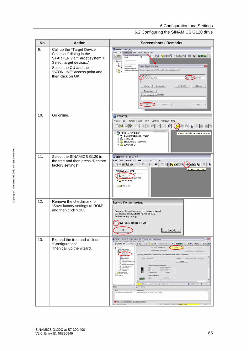
6 Configuration and Settings
6.2 Configuring the SINAMICS G120 drive
SINAMICS G120C at S7-300/400 V2.0, Entry ID: 58820849 65
Co
pyr
igh
t
Sie
me
ns
AG
20
12
All
righ
ts r
ese
rve
d
No. Action Screenshots / Remarks
9. Call up the “Target Device Selection” dialog in the STARTER via “Target system > Select target device...”. Select the CU and the “S7ONLINE” access point and then click on OK.
10. Go online.
11. Select the SINAMICS G120 in the tree and then press “Restore factory settings”.
12. Remove the checkmark for “Save factory settings to ROM” and then click “OK”.
13. Expand the tree and click on “Configuration”. Then call up the wizard.

6 Configuration and Settings
6.2 Configuring the SINAMICS G120 drive
66 SINAMICS G120C at S7-300/400
V2.0, Entry ID: 58820849
Co
pyr
igh
t
Sie
me
ns
AG
20
12
All
righ
ts r
ese
rve
d
No. Action Screenshots / Remarks
14. Run the wizard and enter the data you need. If you have no specific requirements, use the respective default values, apart from the following exceptions
• Ensure that the field bus is selected in the “Defaults of the setpoint/command sources” step.
• In the “Motor” step you enter the data of the connected motor.
After the wizard has been run through completely, double-click on “Communication > PROFINET” in the tree, select one of the “Receive” or “Send direction” tabs, and select “Siemens telegram 352, PZD 6/6)”.
15.
Note: The message frame type and the address match the example. It is decisive here that the same message frame and the same address are selected as for the hardware configuration in STEP 7.
16. If you do not wish to use any safety functions or have a CU without safety functions (e.g. a CU230P-2PN), continue with step 21.
When using an F-CPU you can also call the safety functions via the field bus. However, this is not part of this example. More information on this subject can be found in the Safety Integrated (/7/) function manual for the SINAMICS G120, or in the example with PROFIsafe (/8/).
17. Open “Safety Integrated” in the tree and click on “Change settings”.

6 Configuration and Settings
6.2 Configuring the SINAMICS G120 drive
SINAMICS G120C at S7-300/400 V2.0, Entry ID: 58820849 67
Co
pyr
igh
t
Sie
me
ns
AG
20
12
All
righ
ts r
ese
rve
d
No. Action Screenshots / Remarks
18. Select the “STO via terminal”, click on “Copy parameters” and then on “Activate settings”.
19. Enter a password and then click on “Activate settings again”. (The password used in this example is “12345”)
20. Choose “Yes”, to save the parameters in ROM. Proceed with step 22.
21. Select the SINAMICS G120 in the tree and then press “Copy RAM to ROM”.
22. Load the configuration created online into the PG.
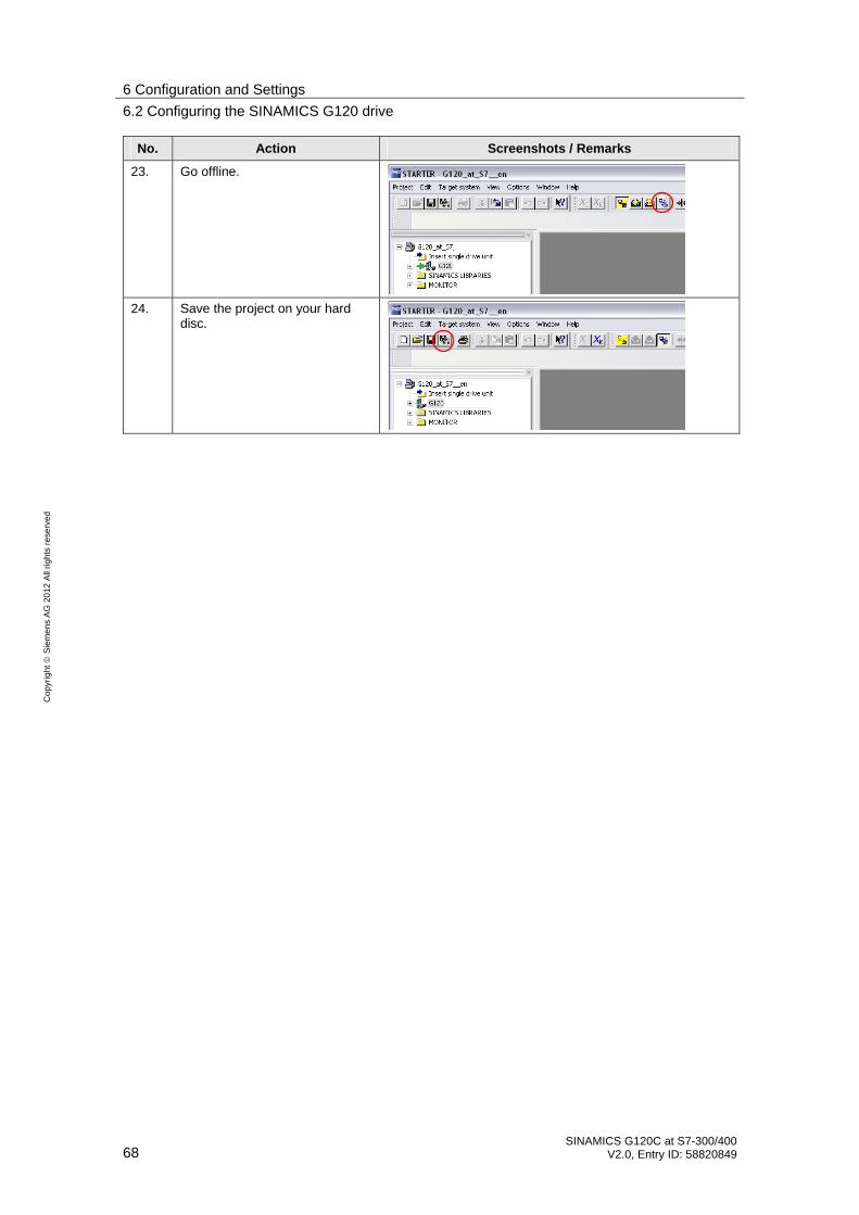
6 Configuration and Settings
6.2 Configuring the SINAMICS G120 drive
68 SINAMICS G120C at S7-300/400
V2.0, Entry ID: 58820849
Co
pyr
igh
t
Sie
me
ns
AG
20
12
All
righ
ts r
ese
rve
d
No. Action Screenshots / Remarks
23. Go offline.
24. Save the project on your hard disc.

7 Links & Literature
SINAMICS G120C at S7-300/400 V2.0, Entry ID: 58820849 69
Co
pyr
igh
t
Sie
me
ns
AG
20
12
All
righ
ts r
ese
rve
d
7 Links & Literature The following list is by no means complete and only provides a selection of appropriate sources.
Table 7-1
Topic Title / link
/1/ Automatisieren mit STEP7 in AWL und SCL (Automating with STEP7 in STL and SCL) Author: Hans Berger Publicis MCD Verlag ISBN: 978-3-89578-397-5
/2/ Automating with STEP 7 in LAD and FBD Author: Hans Berger Publicis MCD Verlag ISBN: 978-3-89578-296-1
/3/
STEP7 SIMATIC S7-300/400
Reference Manual System and Standard Functions for S7-300 and S7400 Volume 1/2 http://support.automation.siemens.com/WW/view/en/44240604
/4/ Link to this document
http://support.automation.siemens.com/WW/view/en/61598730
/5/ Siemens Industry Online Support
http://support.automation.siemens.com
/6/ STARTER http://support.automation.siemens.com/WW/view/en/26233208
SINAMICS G120 Manuals
Operating instructions (V4.5): http://support.automation.siemens.com/WW/view/en/61618946 List manual (V4.5) (parameters and error list):
http://support.automation.siemens.com/WW/view/en/49383082 Function manual Safety Integrated (V4.5): http://support.automation.siemens.com/WW/view/en/59875481
SINAMICS G120C Manuals
Operating instructions (V4.5): http://support.automation.siemens.com/WW/view/en/61462568 List manual (V4.5) (parameters and error list): http://support.automation.siemens.com/WW/view/en/59745599 Function manual Safety Integrated (V4.5):
http://support.automation.siemens.com/WW/view/en/59875481
/7/
SINAMICS G120D Manuals
Operating instructions CU240D-2 (V4.5): http://support.automation.siemens.com/WW/view/en/60448591 Operating instructions CU250D-2 (V4.5): http://support.automation.siemens.com/WW/view/en/60443897 List manual (V4.5) (parameters and error list): http://support.automation.siemens.com/WW/view/en/59745958 Function manual Safety Integrated (V4.5): http://support.automation.siemens.com/WW/view/en/59875481

8 History
70 SINAMICS G120C at S7-300/400
V2.0, Entry ID: 58820849
Co
pyr
igh
t
Sie
me
ns
AG
20
12
All
righ
ts r
ese
rve
d
Topic Title / link
/8/ Application example with PROFIsafe
Connecting a SINAMICS G120, G120C, G120D drive by a fail-safe S7-300/400F CPU via PROFINET or PROFIBUS DP with fail-safe control of the SINAMICS Safety Functions in STEP 7 V5 http://support.automation.siemens.com/WW/view/en/60441457
/9/ FAQ for data record routing
http://support.automation.siemens.com/WW/view/en/7000978
8 History
Table 8-1
Version Date Revisions
V1.0 07/2012 First issue
V2.0 08/2012 Complete revision with focus on easy usability of the blocks in own projects Expansion by SINAMICS G120C, G120D
![MasoSineOverviewBrochure Sine Brochure · Speed [RPM] Capacity [GPM] 0 PSI 150 PSI 25 12.5 0 0 100 200 300400 500 600 MR-125 Speed [RPM] Capacity [GPM] 0 PSI 150 PSI 50 25 0 100 200](https://static.fdocuments.us/doc/165x107/5f0cd0b17e708231d4374467/masosineoverviewbrochure-sine-brochure-speed-rpm-capacity-gpm-0-psi-150-psi.jpg)