58389253 Standard Wiring Practices Manual
100
PARAGRAPH DESCRIPTION PAGE 1. Part Numbers and Description 1 1.A. Switch Part Numbers 1 2. Switch Disassembly 1 2.A. Connector Separation 1 3. Switch Assembly 1 3.A. Plug and the Receptacle Connection 1 1.Part Numbers and Description A. Switch Part Numbers Janco AD45-() switches have these technical features: - Cory or Tri-Star CSLT2-21R() receptacle connectors mounted on the rear - Connect to Cory or Tri-Star CSLT2-21P() plug connectors. Refer to Subject 20-61-29 for assembly of Cory and Tri-Star CSLT2-21P() connectors. TABLE I SWITCH PART NUMBERS Part Number Description Supplier AD45-() Switch, Rotary Janco 2.Switch Disassembly A. Connector Separation Refer to Subject 20-61-29. 3.Switch Assembly A. Plug and the Receptacle Connection Refer to Subject 20-61-29. b STANDARD WIRING PRACTICES MANUAL JANCO AD45-() SWITCHES MANUAL NO: D6-54446 PAGE 1 NOV 01/2005 20-84-17 A-PDF Split DEMO : Purchase from www.A-PDF.com to remove the watermark
-
Upload
matteo1978 -
Category
Documents
-
view
614 -
download
26
description
Wiring practices
Transcript of 58389253 Standard Wiring Practices Manual
PARAGRAPH DESCRIPTION PAGE
1. Part Numbers and Description 11.A. Switch Part Numbers 12. Switch Disassembly 12.A. Connector Separation 13. Switch Assembly 13.A. Plug and the Receptacle Connection 1
1.Part Numbers and Description
A. Switch Part Numbers
Janco AD45-() switches have these technical features:
- Cory or Tri-Star CSLT2-21R() receptacle connectors mounted on the rear- Connect to Cory or Tri-Star CSLT2-21P() plug connectors.
Refer to Subject 20-61-29 for assembly of Cory and Tri-Star CSLT2-21P()connectors.
TABLE ISWITCH PART NUMBERS
Part
NumberDescription Supplier
AD45-() Switch, Rotary Janco
2.Switch Disassembly
A. Connector Separation
Refer to Subject 20-61-29.
3.Switch Assembly
A. Plug and the Receptacle Connection
Refer to Subject 20-61-29.
b
STANDARD WIRING PRACTICES MANUAL
JANCO AD45-() SWITCHES
MANUAL NO: D6-54446 PAGE 1NOV 01/200520-84-17
A-PDF Split DEMO : Purchase from www.A-PDF.com to remove the watermark

This page is intentionally left blank
PARAGRAPH DESCRIPTION PAGE
1. Part Numbers and Description 11.A. Connector Clamp Part Numbers 12. Connector Clamp Disassembly 12.A. Clamp Removal 13. Connector Clamp Assembly 13.A. Clamp Installation 1
1.Part Numbers and Description
A. Connector Clamp Part Numbers
TABLE ICONNECTOR CLAMP PART NUMBERS
Part Number Supplier
G2636-() Glenair
G2918-() Glenair
2.Connector Clamp Disassembly
A. Clamp Removal
(1) Remove the screws from the clamp assembly.
(2) Spread the clamp assembly to remove it from the connector.
3.Connector Clamp Assembly
A. Clamp Installation
(1) Install the connector clamp assembly. Refer to Figure 1.
(2) Tighten the clamp assembly.
Make sure that the torque on the screws is from 10 inch-pounds to 12inch-pounds.
b
STANDARD WIRING PRACTICES MANUAL
ASSEMBLY OF GLENAIR G2636-() AND G2918-() CONNECTOR CLAMPS
MANUAL NO: D6-54446 PAGE 1NOV 01/200520-85-11
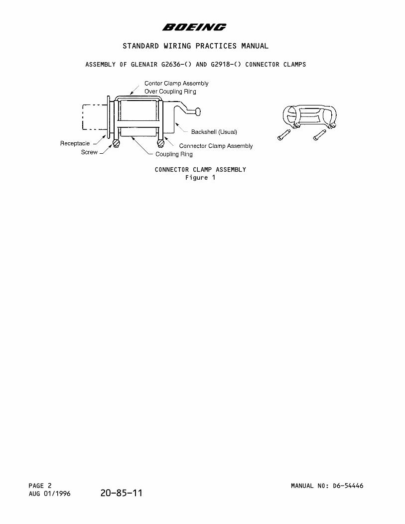
CONNECTOR CLAMP ASSEMBLYFigure 1
b
STANDARD WIRING PRACTICES MANUAL
ASSEMBLY OF GLENAIR G2636-() AND G2918-() CONNECTOR CLAMPS
MANUAL NO: D6-54446PAGE 2AUG 01/1996 20-85-11
This Subject gives the procedures to assemble the landing gear cables for these Model 747,Model 767, and Model 777 systems:
- Anti-Skid- Brake Cooling- Tire Pressure- In-Axle.
PARAGRAPH DESCRIPTION PAGE
1. Part Numbers and Description 11.A. Necessary Parts and Materials 11.B. Configuration of Cable Assemblies 22. Landing Gear Cable Assembly: 747-100,
747-200, 747-3002
2.A. Anti-Skid Cable Assembly 32.B. Brake Cooling Cable Assembly 53. Landing Gear Cable Assembly: 747-400 73.A. Anti-Skid Cable Assembly 73.B. Brake Cooling Cable Assembly 103.C. Tire Pressure Cable Assembly 114. Landing Gear Cable Assembly: 767 134.A. Anti-Skid Cable Assembly 134.B. Brake Cooling and Tire Pressure Cable
Assembly16
5. Landing Gear In-Axle Cable Assembly: 777 195.A. Wire Preparation 195.B. Connector Assembly 23
1.Part Numbers and Description
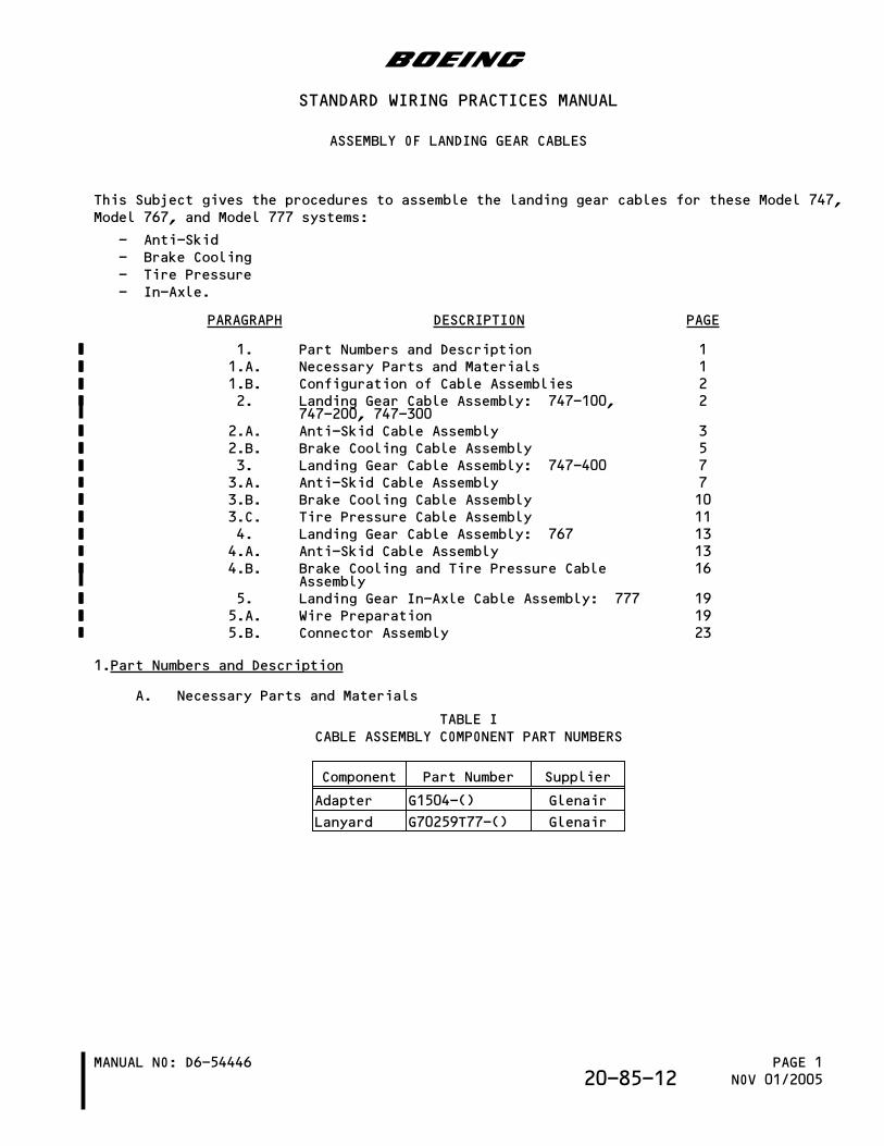
A. Necessary Parts and Materials
TABLE ICABLE ASSEMBLY COMPONENT PART NUMBERS
Component Part Number Supplier
Adapter G1504-() Glenair
Lanyard G70259T77-() Glenair
b
STANDARD WIRING PRACTICES MANUAL
ASSEMBLY OF LANDING GEAR CABLES
MANUAL NO: D6-54446 PAGE 1NOV 01/200520-85-12
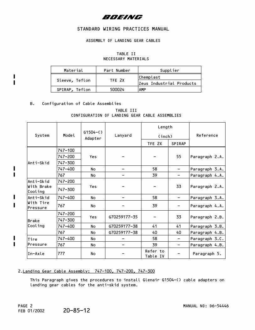
TABLE IINECESSARY MATERIALS
Material Part Number Supplier
Sleeve, Teflon TFE 2XChemplast
Zeus Industrial Products
SPIRAP, Teflon 500024 AMP
B. Configuration of Cable Assemblies
TABLE IIICONFIGURATION OF LANDING GEAR CABLE ASSEMBLIES
System ModelG1504-()
AdapterLanyard
Length
(inch) Reference
TFE 2X SPIRAP
Anti-Skid
747-100
Yes - - 55 Paragraph 2.A.747-200
747-300
747-400 No - 58 - Paragraph 3.A.
767 No - 39 - Paragraph 4.A.
Anti-SkidWith BrakeCooling
747-200Yes - - 33 Paragraph 2.A.
747-300
Anti-SkidWith TirePressure
747-400 No - 58 - Paragraph 3.A.
767 No - 39 - Paragraph 4.A.
BrakeCooling
747-200Yes G70259T77-35 - 33 Paragraph 2.B.
747-300
747-400 No G70259T77-38 41 41 Paragraph 3.B.
767 No G70259T77-38 40 40 Paragraph 4.B.
TirePressure
747-400 No - 58 - Paragraph 3.C.
767 No - 39 - Paragraph 4.B.
In-Axle 777 No -Refer toTable IV
- Paragraph 5.
2.Landing Gear Cable Assembly: 747-100, 747-200, 747-300
This Paragraph gives the procedures to install Glenair G1504-() cable adapters onlanding gear cables for the anti-skid system.
b
STANDARD WIRING PRACTICES MANUAL
ASSEMBLY OF LANDING GEAR CABLES
MANUAL NO: D6-54446PAGE 2FEB 01/2002 20-85-12
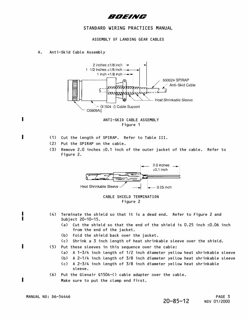
A. Anti-Skid Cable Assembly
ANTI-SKID CABLE ASSEMBLYFigure 1
(1) Cut the length of SPIRAP. Refer to Table III.
(2) Put the SPIRAP on the cable.
(3) Remove 2.0 inches ±0.1 inch of the outer jacket of the cable. Refer toFigure 2.
CABLE SHIELD TERMINATIONFigure 2
(4) Terminate the shield so that it is a dead end. Refer to Figure 2 andSubject 20-10-15.
(a) Cut the shield so that the end of the shield is 0.25 inch ±0.06 inchfrom the end of the jacket.
(b) Fold the shield back over the jacket.
(c) Shrink a 3 inch length of heat shrinkable sleeve over the shield.
(5) Put these sleeves in this sequence over the cable:
(a) A 1-3/4 inch length of 1/2 inch diameter yellow heat shrinkable sleeve
(b) A 2-1/4 inch length of 3/8 inch diameter yellow heat shrinkable sleeve
(c) A 2-3/4 inch length of 3/8 inch diameter yellow heat shrinkablesleeve.
(6) Put the Glenair G1504-() cable adapter over the cable.
Make sure to put the clamp end first.
b
STANDARD WIRING PRACTICES MANUAL
ASSEMBLY OF LANDING GEAR CABLES
MANUAL NO: D6-54446 PAGE 3NOV 01/200020-85-12
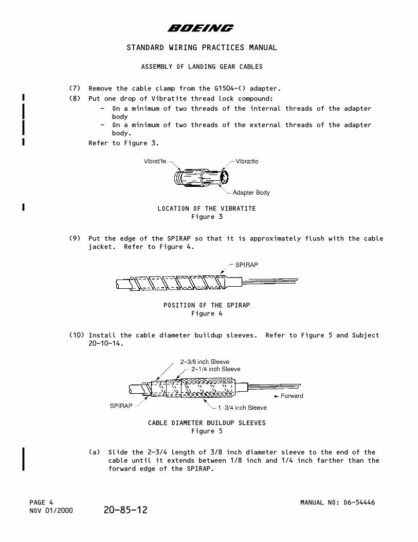
(7) Remove the cable clamp from the G1504-() adapter.
(8) Put one drop of Vibratite thread lock compound:
- On a minimum of two threads of the internal threads of the adapterbody
- On a minimum of two threads of the external threads of the adapterbody.
Refer to Figure 3.
LOCATION OF THE VIBRATITEFigure 3
(9) Put the edge of the SPIRAP so that it is approximately flush with the cablejacket. Refer to Figure 4.
POSITION OF THE SPIRAPFigure 4
(10) Install the cable diameter buildup sleeves. Refer to Figure 5 and Subject20-10-14.
CABLE DIAMETER BUILDUP SLEEVESFigure 5
(a) Slide the 2-3/4 length of 3/8 inch diameter sleeve to the end of thecable until it extends between 1/8 inch and 1/4 inch farther than theforward edge of the SPIRAP.
b
STANDARD WIRING PRACTICES MANUAL
ASSEMBLY OF LANDING GEAR CABLES
MANUAL NO: D6-54446PAGE 4NOV 01/2000 20-85-12
(b) Shrink the sleeve into position. Refer to Subject 20-10-14.
(c) Put the 2-1/4 inch length of 3/8 inch diameter sleeve over the firstsleeve.
(d) Shrink the sleeve into position. Refer to Subject 20-10-14.
(e) Put the 1-3/4 inch length of 1/2 inch diameter sleeve over the secondsleeve.
(f) Shrink the sleeve into position. Refer to Subject 20-10-14.
(11) Assemble the connector. Refer to Subject 20-61-11.
(12) Hold the two conductors immediately forward of the buildup sleeves and pushthem to the connector to make the wires bend.
The wires should remain bent after they are released.
CAUTION: DO NOT GRIP THE BUILDUP SLEEVES TO MAKE THE WIRES BEND. THESLEEVES CAN MOVE OUT OF POSITION.
(13) Move the adapter body forward.
(14) Engage the threads of the adapter and the connector.
(15) Torque the adapter hand tight plus 1/8 of a turn.
(16) Hold the cable and put the forward edge of the buildup sleeves so that theyare flush to 1/8 inch in the end of the adapter body.
Make sure that:
- The sleeve remains in position when the cable is released- The wires have slack in the adapter.
(17) Engage the threads of the cable clamp and the adapter.
(18) Torque the cable clamp hand tight plus 1/8 of a turn.
(19) Tighten the clamp saddle screws.
(20) If the cable clamp does not hold the cable tightly:
(a) Remove the cable clamp from the adapter.
(b) Remove the adapter from the connector.
(c) Remove the contacts from the connector. Refer to Subject 20-61-11.
(d) Put the necessary number of 1 inch lengths of RT-876 or equivalentheat shrinkable sleeves on the cable.
Make sure that each sleeve has the smallest diameter that can moveeasily on the cable.
(e) Align the forward edge of each sleeve with the forward edge of the2-3/4 inch length of heat shrinkable sleeve.
(f) Shrink each sleeve in position. Refer to Subject 20-10-14.
(g) Do Step (11) thru Step (19) again.
Make sure that the clamp holds the cable tightly.
(21) Install safety wires on the saddle screws.
B. Brake Cooling Cable Assembly
(1) Assemble the brake cooling cable but do not tighten the saddle clampscrews. Refer to Paragraph 2.A.
b
STANDARD WIRING PRACTICES MANUAL
ASSEMBLY OF LANDING GEAR CABLES
MANUAL NO: D6-54446 PAGE 5NOV 01/200020-85-12
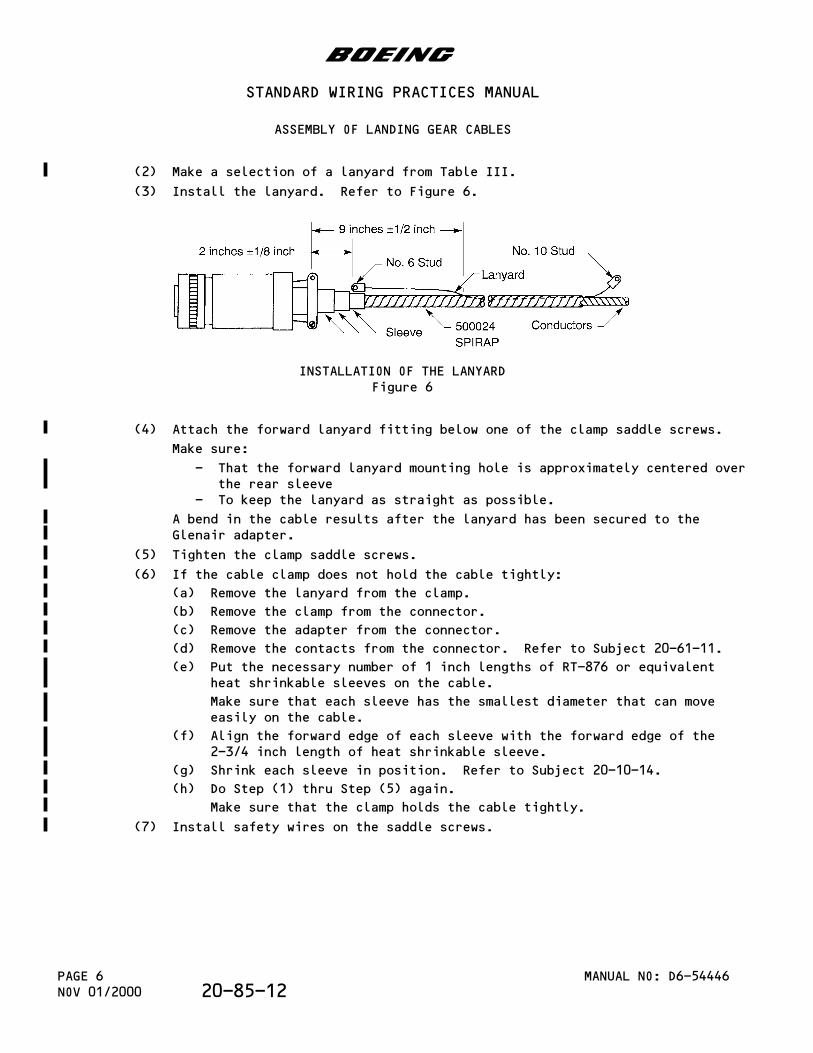
(2) Make a selection of a lanyard from Table III.
(3) Install the lanyard. Refer to Figure 6.
INSTALLATION OF THE LANYARDFigure 6
(4) Attach the forward lanyard fitting below one of the clamp saddle screws.
Make sure:
- That the forward lanyard mounting hole is approximately centered overthe rear sleeve
- To keep the lanyard as straight as possible.
A bend in the cable results after the lanyard has been secured to theGlenair adapter.
(5) Tighten the clamp saddle screws.
(6) If the cable clamp does not hold the cable tightly:
(a) Remove the lanyard from the clamp.
(b) Remove the clamp from the connector.
(c) Remove the adapter from the connector.
(d) Remove the contacts from the connector. Refer to Subject 20-61-11.
(e) Put the necessary number of 1 inch lengths of RT-876 or equivalentheat shrinkable sleeves on the cable.
Make sure that each sleeve has the smallest diameter that can moveeasily on the cable.
(f) Align the forward edge of each sleeve with the forward edge of the2-3/4 inch length of heat shrinkable sleeve.
(g) Shrink each sleeve in position. Refer to Subject 20-10-14.
(h) Do Step (1) thru Step (5) again.
Make sure that the clamp holds the cable tightly.
(7) Install safety wires on the saddle screws.
b
STANDARD WIRING PRACTICES MANUAL
ASSEMBLY OF LANDING GEAR CABLES
MANUAL NO: D6-54446PAGE 6NOV 01/2000 20-85-12
3.Landing Gear Cable Assembly: 747-400
A. Anti-Skid Cable Assembly
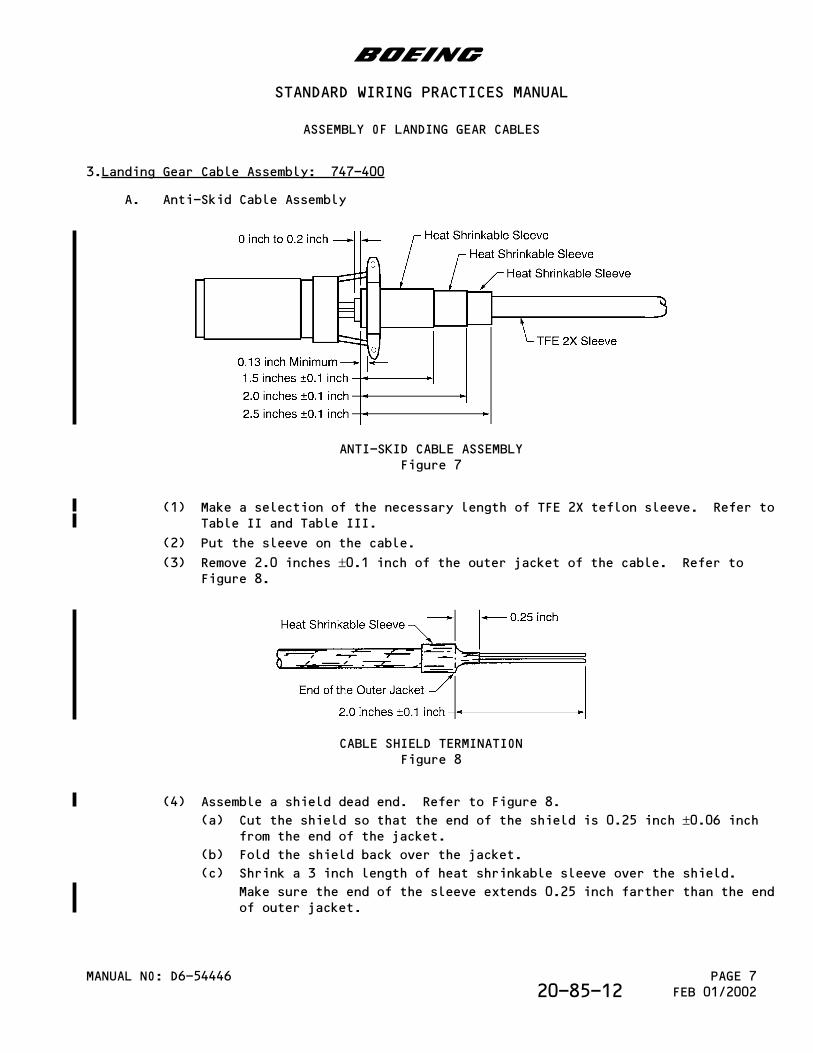
ANTI-SKID CABLE ASSEMBLYFigure 7
(1) Make a selection of the necessary length of TFE 2X teflon sleeve. Refer toTable II and Table III.
(2) Put the sleeve on the cable.
(3) Remove 2.0 inches ±0.1 inch of the outer jacket of the cable. Refer toFigure 8.
CABLE SHIELD TERMINATIONFigure 8
(4) Assemble a shield dead end. Refer to Figure 8.
(a) Cut the shield so that the end of the shield is 0.25 inch ±0.06 inchfrom the end of the jacket.
(b) Fold the shield back over the jacket.
(c) Shrink a 3 inch length of heat shrinkable sleeve over the shield.
Make sure the end of the sleeve extends 0.25 inch farther than the endof outer jacket.
b
STANDARD WIRING PRACTICES MANUAL
ASSEMBLY OF LANDING GEAR CABLES
MANUAL NO: D6-54446 PAGE 7FEB 01/200220-85-12
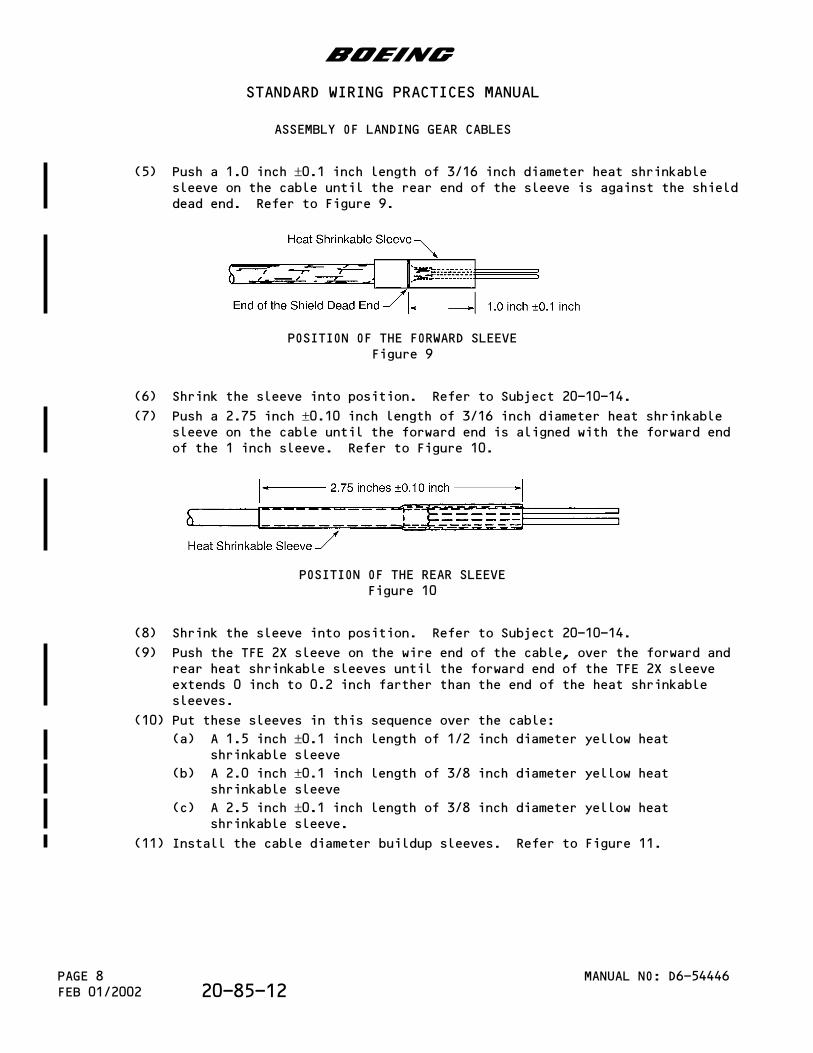
(5) Push a 1.0 inch ±0.1 inch length of 3/16 inch diameter heat shrinkablesleeve on the cable until the rear end of the sleeve is against the shielddead end. Refer to Figure 9.
POSITION OF THE FORWARD SLEEVEFigure 9
(6) Shrink the sleeve into position. Refer to Subject 20-10-14.
(7) Push a 2.75 inch ±0.10 inch length of 3/16 inch diameter heat shrinkablesleeve on the cable until the forward end is aligned with the forward endof the 1 inch sleeve. Refer to Figure 10.
POSITION OF THE REAR SLEEVEFigure 10
(8) Shrink the sleeve into position. Refer to Subject 20-10-14.
(9) Push the TFE 2X sleeve on the wire end of the cable, over the forward andrear heat shrinkable sleeves until the forward end of the TFE 2X sleeveextends 0 inch to 0.2 inch farther than the end of the heat shrinkablesleeves.
(10) Put these sleeves in this sequence over the cable:
(a) A 1.5 inch ±0.1 inch length of 1/2 inch diameter yellow heatshrinkable sleeve
(b) A 2.0 inch ±0.1 inch length of 3/8 inch diameter yellow heatshrinkable sleeve
(c) A 2.5 inch ±0.1 inch length of 3/8 inch diameter yellow heatshrinkable sleeve.
(11) Install the cable diameter buildup sleeves. Refer to Figure 11.
b
STANDARD WIRING PRACTICES MANUAL
ASSEMBLY OF LANDING GEAR CABLES
MANUAL NO: D6-54446PAGE 8FEB 01/2002 20-85-12
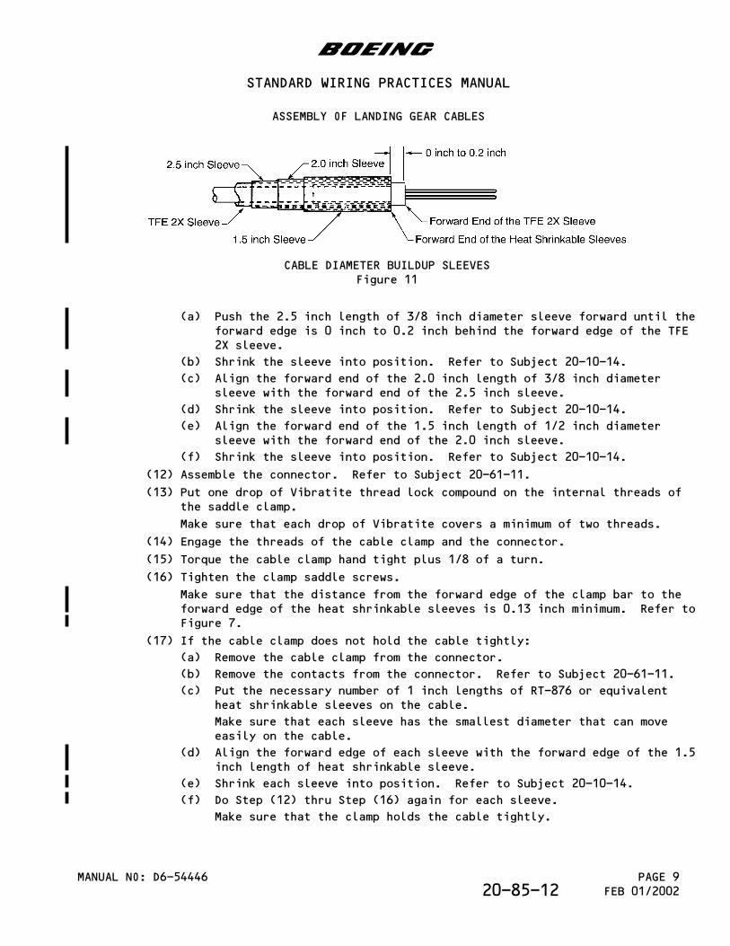
CABLE DIAMETER BUILDUP SLEEVESFigure 11
(a) Push the 2.5 inch length of 3/8 inch diameter sleeve forward until theforward edge is 0 inch to 0.2 inch behind the forward edge of the TFE2X sleeve.
(b) Shrink the sleeve into position. Refer to Subject 20-10-14.
(c) Align the forward end of the 2.0 inch length of 3/8 inch diametersleeve with the forward end of the 2.5 inch sleeve.
(d) Shrink the sleeve into position. Refer to Subject 20-10-14.
(e) Align the forward end of the 1.5 inch length of 1/2 inch diametersleeve with the forward end of the 2.0 inch sleeve.
(f) Shrink the sleeve into position. Refer to Subject 20-10-14.
(12) Assemble the connector. Refer to Subject 20-61-11.
(13) Put one drop of Vibratite thread lock compound on the internal threads ofthe saddle clamp.
Make sure that each drop of Vibratite covers a minimum of two threads.
(14) Engage the threads of the cable clamp and the connector.
(15) Torque the cable clamp hand tight plus 1/8 of a turn.
(16) Tighten the clamp saddle screws.
Make sure that the distance from the forward edge of the clamp bar to theforward edge of the heat shrinkable sleeves is 0.13 inch minimum. Refer toFigure 7.
(17) If the cable clamp does not hold the cable tightly:
(a) Remove the cable clamp from the connector.
(b) Remove the contacts from the connector. Refer to Subject 20-61-11.
(c) Put the necessary number of 1 inch lengths of RT-876 or equivalentheat shrinkable sleeves on the cable.
Make sure that each sleeve has the smallest diameter that can moveeasily on the cable.
(d) Align the forward edge of each sleeve with the forward edge of the 1.5inch length of heat shrinkable sleeve.
(e) Shrink each sleeve into position. Refer to Subject 20-10-14.
(f) Do Step (12) thru Step (16) again for each sleeve.
Make sure that the clamp holds the cable tightly.
b
STANDARD WIRING PRACTICES MANUAL
ASSEMBLY OF LANDING GEAR CABLES
MANUAL NO: D6-54446 PAGE 9FEB 01/200220-85-12
(18) Install safety wires the saddle screws.
B. Brake Cooling Cable Assembly
(1) Cut the length of the TFE 2X sleeve. Refer to Table III.
(2) Put the TFE 2X sleeve on the cable so that it is 0.9 inch from the cableend.
(3) Put a 2-1/2 inch length of 3/8 inch diameter heat shrinkable sleeve overthe TFE 2X sleeve.
(4) Shrink the sleeve into position. Refer to Subject 20-10-14.
(5) Cut the length of SPIRAP. Refer to Table III.
(6) Put the SPIRAP on the cable over the TFE 2X sleeve.
(7) Put a 2 inch length of 1/2 inch diameter heat shrinkable sleeve over theSPIRAP.
(8) Shrink the sleeve into position. Refer to Subject 20-10-14.
(9) Put a 1-1/2 inch length of 1/2 inch diameter heat shrinkable sleeve overthe SPIRAP and the first sleeve.
(10) Shrink the sleeve into position. Refer to Subject 20-10-14.
(11) Assemble the connector. Refer to Subject 20-61-11.
(12) Put one drop of Vibratite thread lock compound on the internal threads ofthe saddle clamp.
Make sure that each drop of Vibratite covers a minimum of two threads.
(13) Engage the threads of the cable clamp and the connector.
(14) Torque the cable clamp hand tight plus 1/8 of a turn.
(15) Make a selection of a lanyard from Table III.
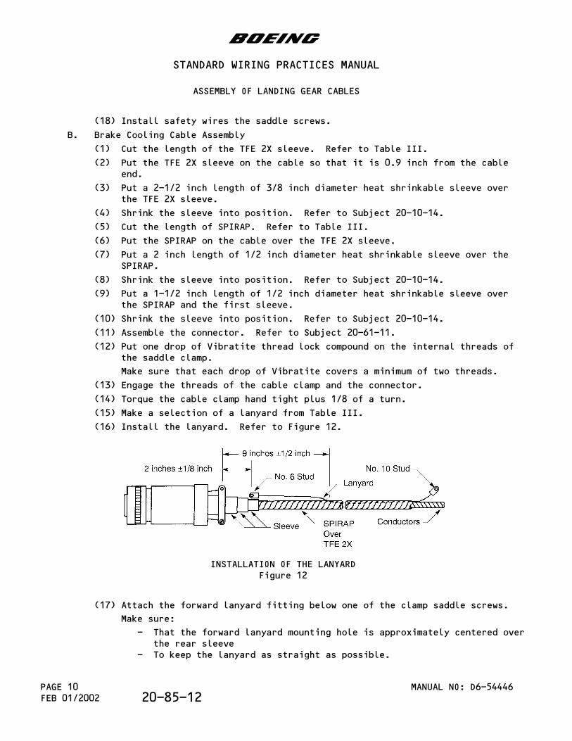
(16) Install the lanyard. Refer to Figure 12.
INSTALLATION OF THE LANYARDFigure 12
(17) Attach the forward lanyard fitting below one of the clamp saddle screws.
Make sure:
- That the forward lanyard mounting hole is approximately centered overthe rear sleeve
- To keep the lanyard as straight as possible.
b
STANDARD WIRING PRACTICES MANUAL
ASSEMBLY OF LANDING GEAR CABLES
MANUAL NO: D6-54446PAGE 10FEB 01/2002 20-85-12
A bend in the cable will result after the lanyard has been secured to theGlenair adapter.
(18) Tighten the clamp saddle screws.
(19) If the cable clamp does not hold the cable tightly:
(a) Remove the lanyard from the clamp.
(b) Remove the clamp from the connector.
(c) Remove the contacts from the connector. Refer to Subject 20-61-11.
(d) Put the necessary number of 1 inch lengths of RT-876 or equivalentheat shrinkable sleeves on the cable.
Make sure that each sleeve has the smallest diameter that can moveeasily on the cable.
(e) Align the forward edge of each sleeve with the forward edge of the1-1/2 inch length of heat shrinkable sleeve.
(f) Shrink each sleeve in position. Refer to Subject 20-10-14.
(g) Do Step (11) thru Step (18) again.
Make sure that the clamp holds the cable tightly.
(20) Install safety wires the on the saddle screws.
C. Tire Pressure Cable Assembly
(1) Cut the length of the TFE 2X sleeve. Refer to Table III.
(2) Put the TFE 2X on the cable.
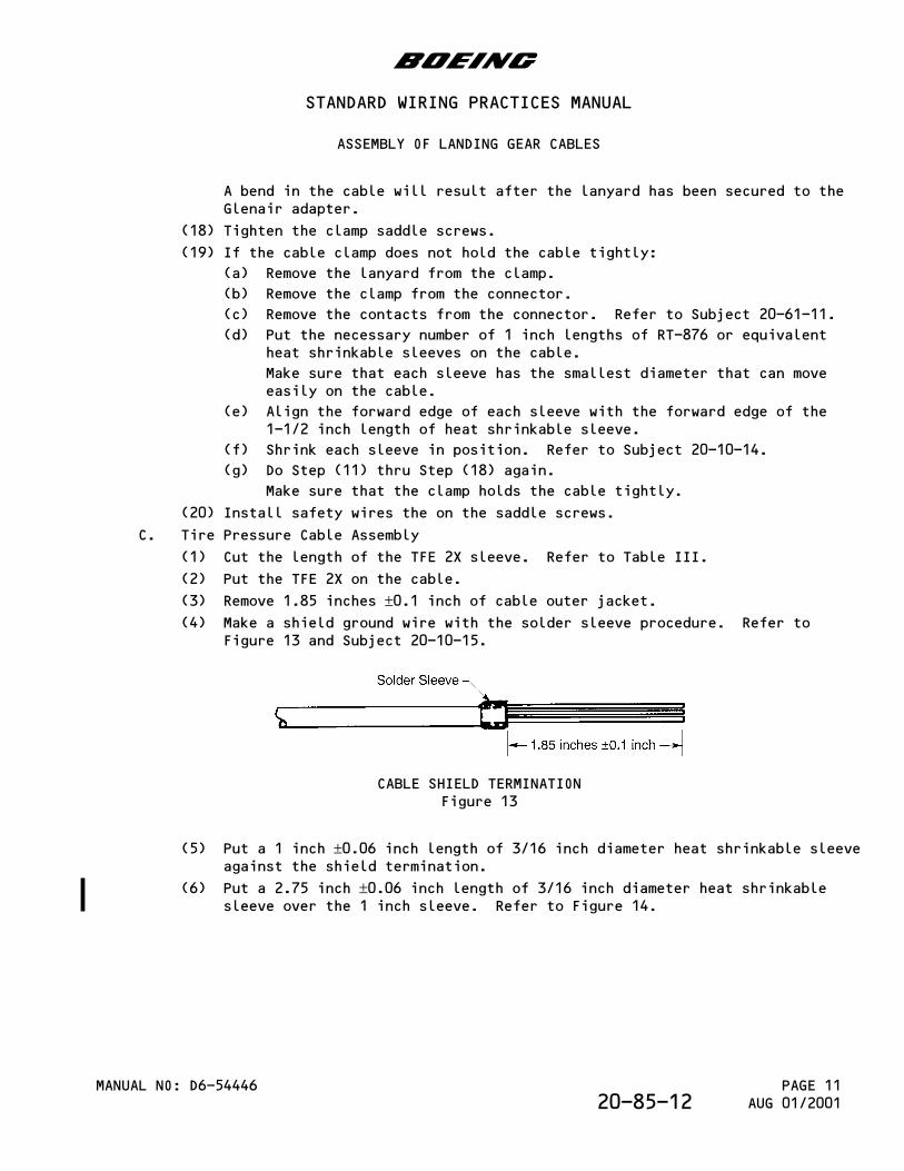
(3) Remove 1.85 inches ±0.1 inch of cable outer jacket.(4) Make a shield ground wire with the solder sleeve procedure. Refer to
Figure 13 and Subject 20-10-15.
CABLE SHIELD TERMINATIONFigure 13
(5) Put a 1 inch ±0.06 inch length of 3/16 inch diameter heat shrinkable sleeveagainst the shield termination.
(6) Put a 2.75 inch ±0.06 inch length of 3/16 inch diameter heat shrinkablesleeve over the 1 inch sleeve. Refer to Figure 14.
b
STANDARD WIRING PRACTICES MANUAL
ASSEMBLY OF LANDING GEAR CABLES
MANUAL NO: D6-54446 PAGE 11AUG 01/200120-85-12
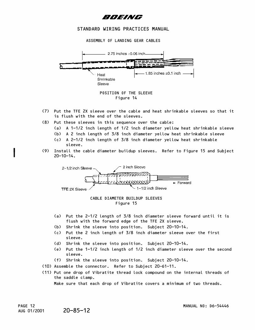
POSITION OF THE SLEEVEFigure 14
(7) Put the TFE 2X sleeve over the cable and heat shrinkable sleeves so that itis flush with the end of the sleeves.
(8) Put these sleeves in this sequence over the cable:
(a) A 1-1/2 inch length of 1/2 inch diameter yellow heat shrinkable sleeve
(b) A 2 inch length of 3/8 inch diameter yellow heat shrinkable sleeve
(c) A 2-1/2 inch length of 3/8 inch diameter yellow heat shrinkablesleeve.
(9) Install the cable diameter buildup sleeves. Refer to Figure 15 and Subject20-10-14.
CABLE DIAMETER BUILDUP SLEEVESFigure 15
(a) Put the 2-1/2 length of 3/8 inch diameter sleeve forward until it isflush with the forward edge of the TFE 2X sleeve.
(b) Shrink the sleeve into position. Subject 20-10-14.
(c) Put the 2 inch length of 3/8 inch diameter sleeve over the firstsleeve.
(d) Shrink the sleeve into position. Subject 20-10-14.
(e) Put the 1-1/2 inch length of 1/2 inch diameter sleeve over the secondsleeve.
(f) Shrink the sleeve into position. Subject 20-10-14.
(10) Assemble the connector. Refer to Subject 20-61-11.
(11) Put one drop of Vibratite thread lock compound on the internal threads ofthe saddle clamp.
Make sure that each drop of Vibratite covers a minimum of two threads.
b
STANDARD WIRING PRACTICES MANUAL
ASSEMBLY OF LANDING GEAR CABLES
MANUAL NO: D6-54446PAGE 12AUG 01/2001 20-85-12
(12) Engage the threads of the cable clamp and the connector.
(13) Torque the cable clamp hand tight plus 1/8 of a turn.
(14) Tighten the clamp saddle screws.
(15) If the cable clamp does not hold the cable tightly:
(a) Remove the cable clamp from the connector.
(b) Remove the contacts from the connector. Refer to Subject 20-61-11.
(c) Put the necessary number of 1 inch lengths of RT-876 or equivalentheat shrinkable sleeves on the cable.
Make sure that each sleeve has the smallest diameter that can moveeasily on the cable.
(d) Align the forward edge of each sleeve with the forward edge of the1-1/2 inch length of heat shrinkable sleeve.
(e) Shrink each sleeve in position. Refer to Subject 20-10-14.
(f) Do Step (10) thru Step (14) again.
Make sure that the clamp holds the cable tightly.
(16) Install safety wires the on the saddle screws.
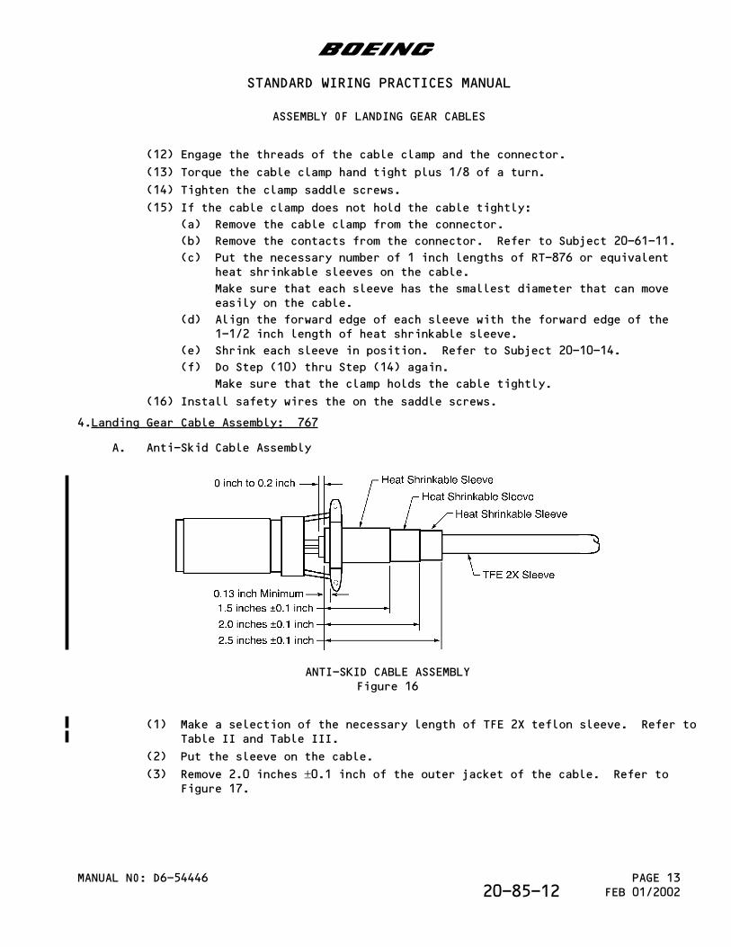
4.Landing Gear Cable Assembly: 767
A. Anti-Skid Cable Assembly
ANTI-SKID CABLE ASSEMBLYFigure 16
(1) Make a selection of the necessary length of TFE 2X teflon sleeve. Refer toTable II and Table III.
(2) Put the sleeve on the cable.
(3) Remove 2.0 inches ±0.1 inch of the outer jacket of the cable. Refer toFigure 17.
b
STANDARD WIRING PRACTICES MANUAL
ASSEMBLY OF LANDING GEAR CABLES
MANUAL NO: D6-54446 PAGE 13FEB 01/200220-85-12
CABLE SHIELD TERMINATIONFigure 17
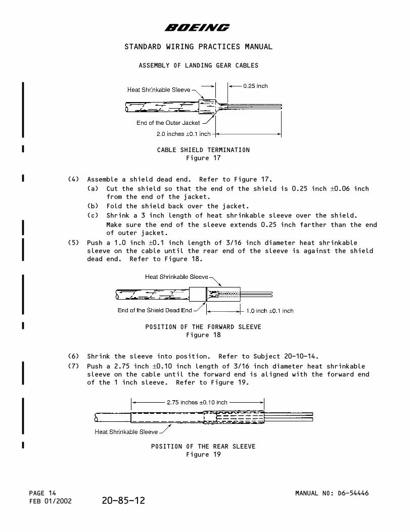
(4) Assemble a shield dead end. Refer to Figure 17.
(a) Cut the shield so that the end of the shield is 0.25 inch ±0.06 inchfrom the end of the jacket.
(b) Fold the shield back over the jacket.
(c) Shrink a 3 inch length of heat shrinkable sleeve over the shield.
Make sure the end of the sleeve extends 0.25 inch farther than the endof outer jacket.
(5) Push a 1.0 inch ±0.1 inch length of 3/16 inch diameter heat shrinkablesleeve on the cable until the rear end of the sleeve is against the shielddead end. Refer to Figure 18.
POSITION OF THE FORWARD SLEEVEFigure 18
(6) Shrink the sleeve into position. Refer to Subject 20-10-14.
(7) Push a 2.75 inch ±0.10 inch length of 3/16 inch diameter heat shrinkablesleeve on the cable until the forward end is aligned with the forward endof the 1 inch sleeve. Refer to Figure 19.
POSITION OF THE REAR SLEEVEFigure 19
b
STANDARD WIRING PRACTICES MANUAL
ASSEMBLY OF LANDING GEAR CABLES
MANUAL NO: D6-54446PAGE 14FEB 01/2002 20-85-12
(8) Shrink the sleeve into position. Refer to Subject 20-10-14.
(9) Push the TFE 2X sleeve on the wire end of the cable, over the forward andrear heat shrinkable sleeves until the forward end of the TFE 2X sleeveextends 0 inch to 0.2 inch farther than the end of the heat shrinkablesleeves.
(10) Put these sleeves in this sequence over the cable:
(a) A 1.5 inch ±0.1 inch length of 1/2 inch diameter yellow heatshrinkable sleeve
(b) A 2.0 inch ±0.1 inch length of 3/8 inch diameter yellow heatshrinkable sleeve
(c) A 2.5 inch ±0.1 inch length of 3/8 inch diameter yellow heatshrinkable sleeve.
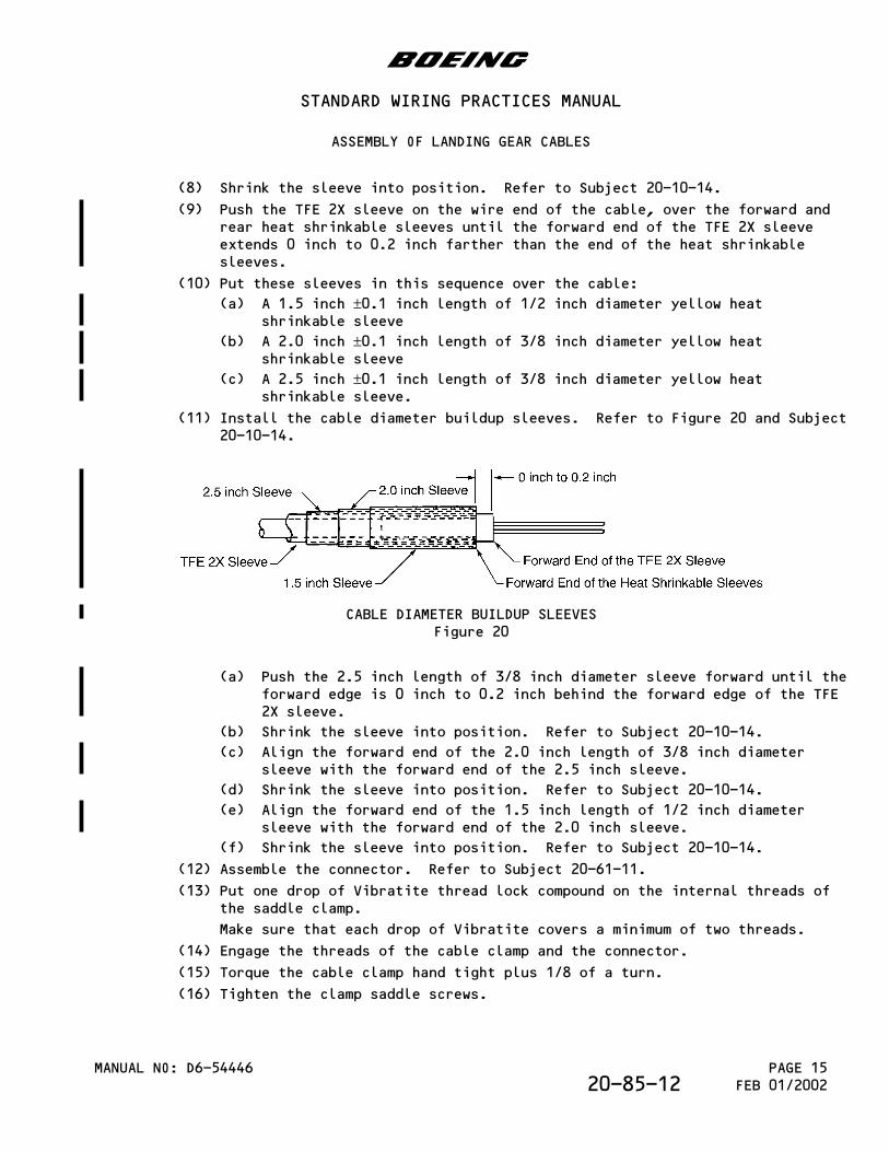
(11) Install the cable diameter buildup sleeves. Refer to Figure 20 and Subject20-10-14.
CABLE DIAMETER BUILDUP SLEEVESFigure 20
(a) Push the 2.5 inch length of 3/8 inch diameter sleeve forward until theforward edge is 0 inch to 0.2 inch behind the forward edge of the TFE2X sleeve.
(b) Shrink the sleeve into position. Refer to Subject 20-10-14.
(c) Align the forward end of the 2.0 inch length of 3/8 inch diametersleeve with the forward end of the 2.5 inch sleeve.
(d) Shrink the sleeve into position. Refer to Subject 20-10-14.
(e) Align the forward end of the 1.5 inch length of 1/2 inch diametersleeve with the forward end of the 2.0 inch sleeve.
(f) Shrink the sleeve into position. Refer to Subject 20-10-14.
(12) Assemble the connector. Refer to Subject 20-61-11.
(13) Put one drop of Vibratite thread lock compound on the internal threads ofthe saddle clamp.
Make sure that each drop of Vibratite covers a minimum of two threads.
(14) Engage the threads of the cable clamp and the connector.
(15) Torque the cable clamp hand tight plus 1/8 of a turn.
(16) Tighten the clamp saddle screws.
b
STANDARD WIRING PRACTICES MANUAL
ASSEMBLY OF LANDING GEAR CABLES
MANUAL NO: D6-54446 PAGE 15FEB 01/200220-85-12
Make sure that the distance from the forward edge of the clamp bar to theforward edge of the heat shrinkable sleeves is 0.13 inch minimum. Refer toFigure 16.
(17) If the cable clamp does not hold the cable tightly:
(a) Remove the cable clamp from the connector.
(b) Remove the contacts from the connector. Refer to Subject 20-61-11.
(c) Put the necessary number of 1 inch lengths of RT-876 or equivalentheat shrinkable sleeves on the cable.
Make sure that each sleeve has the smallest diameter that can moveeasily on the cable.
(d) Align the forward edge of each sleeve with the forward edge of the 1.5inch length of heat shrinkable sleeve.
(e) Shrink each sleeve into position. Refer to Subject 20-10-14.
(f) Do Step (12) thru Step (16) again for each sleeve.
Make sure that the clamp holds the cable tightly.
(18) Install safety wires the on the saddle screws.
B. Brake Cooling and Tire Pressure Cable Assembly
(1) Cut the length of the TFE 2X sleeve. Refer to Table III.
(2) Put the TFE 2X on the cable.
(3) Cut the length of SPIRAP. Refer to Table III.
(4) Put the SPIRAP on the cable over the TFE 2X sleeve.
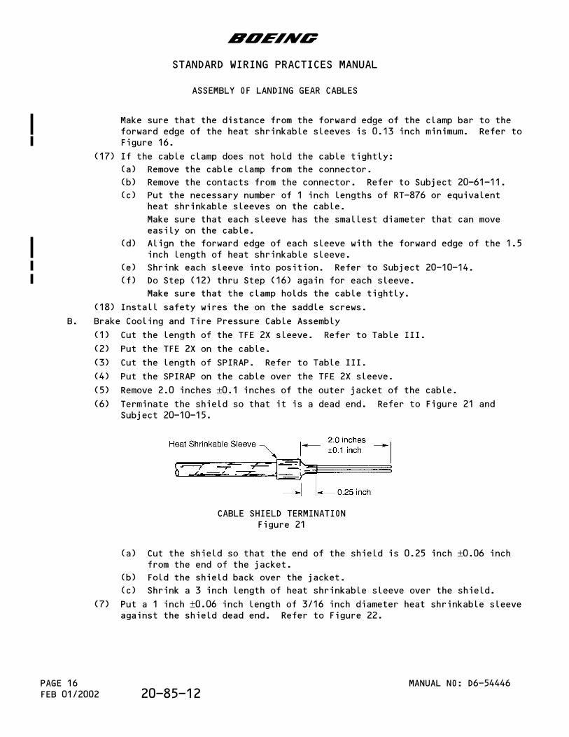
(5) Remove 2.0 inches ±0.1 inches of the outer jacket of the cable.(6) Terminate the shield so that it is a dead end. Refer to Figure 21 and
Subject 20-10-15.
CABLE SHIELD TERMINATIONFigure 21
(a) Cut the shield so that the end of the shield is 0.25 inch ±0.06 inchfrom the end of the jacket.
(b) Fold the shield back over the jacket.
(c) Shrink a 3 inch length of heat shrinkable sleeve over the shield.
(7) Put a 1 inch ±0.06 inch length of 3/16 inch diameter heat shrinkable sleeveagainst the shield dead end. Refer to Figure 22.
b
STANDARD WIRING PRACTICES MANUAL
ASSEMBLY OF LANDING GEAR CABLES
MANUAL NO: D6-54446PAGE 16FEB 01/2002 20-85-12
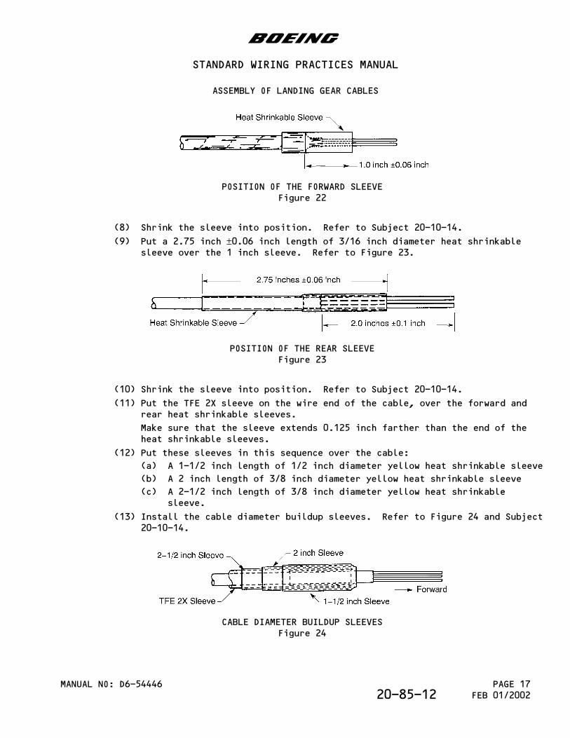
POSITION OF THE FORWARD SLEEVEFigure 22
(8) Shrink the sleeve into position. Refer to Subject 20-10-14.
(9) Put a 2.75 inch ±0.06 inch length of 3/16 inch diameter heat shrinkablesleeve over the 1 inch sleeve. Refer to Figure 23.
POSITION OF THE REAR SLEEVEFigure 23
(10) Shrink the sleeve into position. Refer to Subject 20-10-14.
(11) Put the TFE 2X sleeve on the wire end of the cable, over the forward andrear heat shrinkable sleeves.
Make sure that the sleeve extends 0.125 inch farther than the end of theheat shrinkable sleeves.
(12) Put these sleeves in this sequence over the cable:
(a) A 1-1/2 inch length of 1/2 inch diameter yellow heat shrinkable sleeve
(b) A 2 inch length of 3/8 inch diameter yellow heat shrinkable sleeve
(c) A 2-1/2 inch length of 3/8 inch diameter yellow heat shrinkablesleeve.
(13) Install the cable diameter buildup sleeves. Refer to Figure 24 and Subject20-10-14.
CABLE DIAMETER BUILDUP SLEEVESFigure 24
b
STANDARD WIRING PRACTICES MANUAL
ASSEMBLY OF LANDING GEAR CABLES
MANUAL NO: D6-54446 PAGE 17FEB 01/200220-85-12
(a) Put the 2-1/2 length of 3/8 inch diameter sleeve forward until it isflush with the forward edge of the TFE 2X sleeve.
(b) Shrink the sleeve into position. Refer to Subject 20-10-14.
(c) Put the 2 inch length of 3/8 inch diameter sleeve over the firstsleeve.
(d) Shrink the sleeve into position. Refer to Subject 20-10-14.
(e) Put the 1-1/2 inch length of 1/2 inch diameter sleeve over the secondsleeve.
(f) Shrink the sleeve into position. Refer to Subject 20-10-14.
(14) Assemble the connector. Refer to Subject 20-61-11.
(15) Put one drop of Vibratite thread lock compound on the internal threads ofthe saddle clamp.
Make sure that each drop of Vibratite covers a minimum of two threads.
(16) Engage the threads of the cable clamp and the connector.
(17) Torque the cable clamp hand tight plus 1/8 of a turn.
(18) Make a selection of a lanyard from Table III.
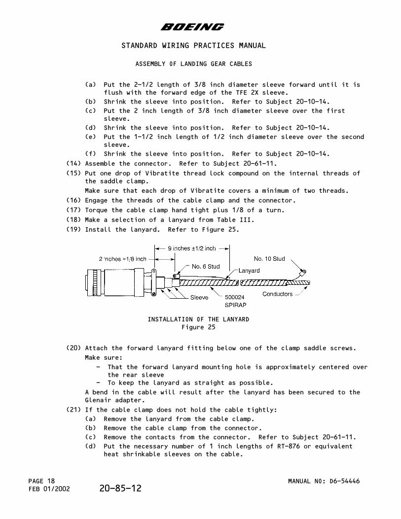
(19) Install the lanyard. Refer to Figure 25.
INSTALLATION OF THE LANYARDFigure 25
(20) Attach the forward lanyard fitting below one of the clamp saddle screws.
Make sure:
- That the forward lanyard mounting hole is approximately centered overthe rear sleeve
- To keep the lanyard as straight as possible.
A bend in the cable will result after the lanyard has been secured to theGlenair adapter.
(21) If the cable clamp does not hold the cable tightly:
(a) Remove the lanyard from the cable clamp.
(b) Remove the cable clamp from the connector.
(c) Remove the contacts from the connector. Refer to Subject 20-61-11.
(d) Put the necessary number of 1 inch lengths of RT-876 or equivalentheat shrinkable sleeves on the cable.
b
STANDARD WIRING PRACTICES MANUAL
ASSEMBLY OF LANDING GEAR CABLES
MANUAL NO: D6-54446PAGE 18FEB 01/2002 20-85-12
Make sure that each sleeve has the smallest diameter that can moveeasily on the cable.
(e) Align the forward edge of each sleeve with the forward edge of the1-1/2 inch length of heat shrinkable sleeve.
(f) Shrink each sleeve in position. Refer to Subject 20-10-14.
(g) Do Step (14) thru Step (20) again.
Make sure that the clamp holds the cable tightly.
(22) If the cable clamp does not hold the cable tightly, install the necessarynumber of 1 inch heat shrinkable sleeves.
(23) Install safety wires on the saddle screws.
5.Landing Gear In-Axle Cable Assembly: 777
A. Wire Preparation
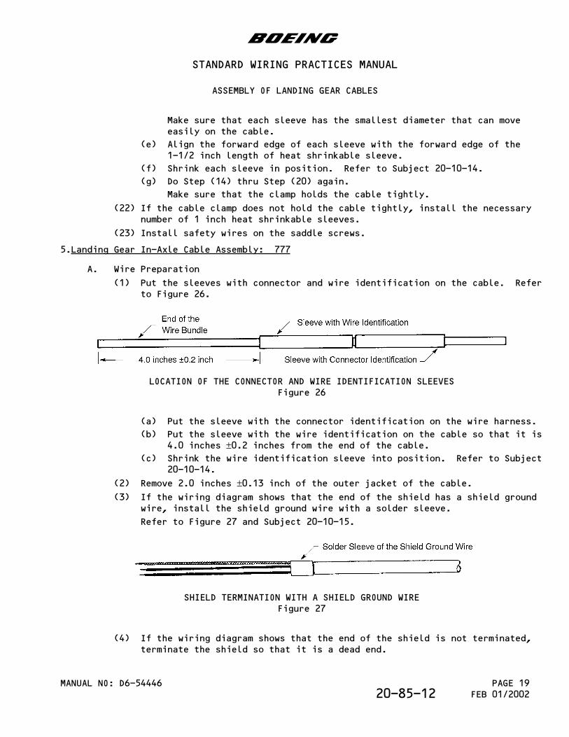
(1) Put the sleeves with connector and wire identification on the cable. Referto Figure 26.
LOCATION OF THE CONNECTOR AND WIRE IDENTIFICATION SLEEVESFigure 26
(a) Put the sleeve with the connector identification on the wire harness.
(b) Put the sleeve with the wire identification on the cable so that it is4.0 inches ±0.2 inches from the end of the cable.
(c) Shrink the wire identification sleeve into position. Refer to Subject20-10-14.
(2) Remove 2.0 inches ±0.13 inch of the outer jacket of the cable.(3) If the wiring diagram shows that the end of the shield has a shield ground
wire, install the shield ground wire with a solder sleeve.
Refer to Figure 27 and Subject 20-10-15.
SHIELD TERMINATION WITH A SHIELD GROUND WIREFigure 27
(4) If the wiring diagram shows that the end of the shield is not terminated,terminate the shield so that it is a dead end.
b
STANDARD WIRING PRACTICES MANUAL
ASSEMBLY OF LANDING GEAR CABLES
MANUAL NO: D6-54446 PAGE 19FEB 01/200220-85-12
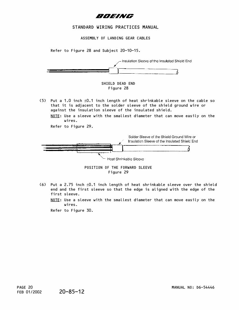
Refer to Figure 28 and Subject 20-10-15.
SHIELD DEAD ENDFigure 28
(5) Put a 1.0 inch ±0.1 inch length of heat shrinkable sleeve on the cable sothat it is adjacent to the solder sleeve of the shield ground wire oragainst the insulation sleeve of the insulated shield.
NOTE: Use a sleeve with the smallest diameter that can move easily on thewires.
Refer to Figure 29.
POSITION OF THE FORWARD SLEEVEFigure 29
(6) Put a 2.75 inch ±0.1 inch length of heat shrinkable sleeve over the shieldend and the first sleeve so that the edge is aligned with the edge of thefirst sleeve.
NOTE: Use a sleeve with the smallest diameter that can move easily on thewires.
Refer to Figure 30.
b
STANDARD WIRING PRACTICES MANUAL
ASSEMBLY OF LANDING GEAR CABLES
MANUAL NO: D6-54446PAGE 20FEB 01/2002 20-85-12
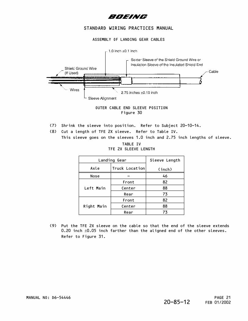
OUTER CABLE END SLEEVE POSITIONFigure 30
(7) Shrink the sleeve into position. Refer to Subject 20-10-14.
(8) Cut a length of TFE 2X sleeve. Refer to Table IV.
This sleeve goes on the sleeves 1.0 inch and 2.75 inch lengths of sleeve.
TABLE IVTFE 2X SLEEVE LENGTH
Landing Gear Sleeve Length
(inch)Axle Truck Location
Nose - 46
Left Main
Front 82
Center 88
Rear 73
Right Main
Front 82
Center 88
Rear 73
(9) Put the TFE 2X sleeve on the cable so that the end of the sleeve extends0.20 inch ±0.05 inch farther than the aligned end of the other sleeves.Refer to Figure 31.
b
STANDARD WIRING PRACTICES MANUAL
ASSEMBLY OF LANDING GEAR CABLES
MANUAL NO: D6-54446 PAGE 21FEB 01/200220-85-12
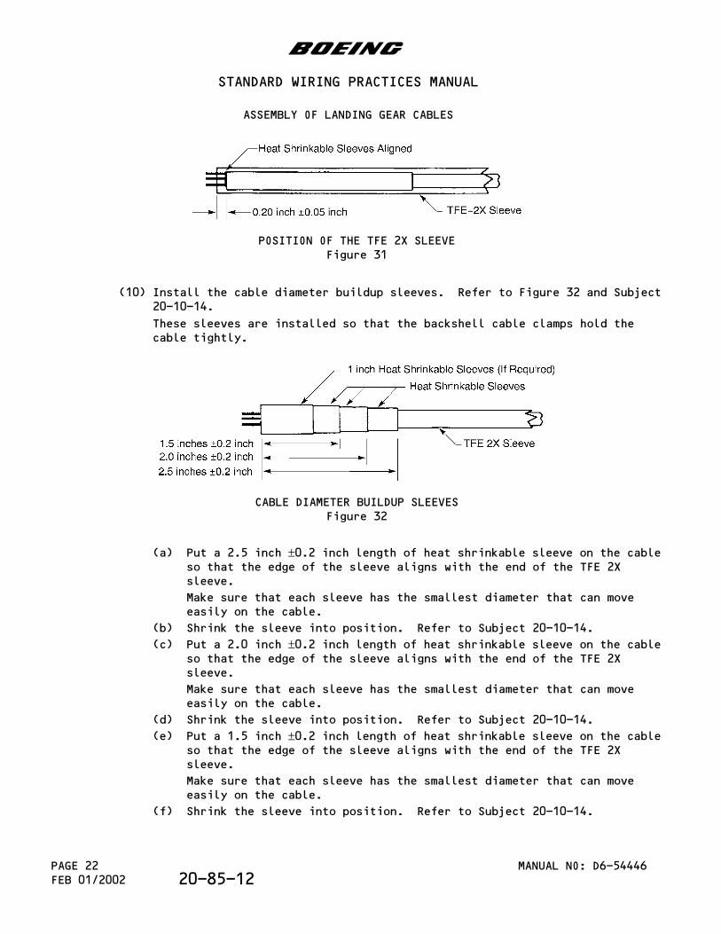
POSITION OF THE TFE 2X SLEEVEFigure 31
(10) Install the cable diameter buildup sleeves. Refer to Figure 32 and Subject20-10-14.
These sleeves are installed so that the backshell cable clamps hold thecable tightly.
CABLE DIAMETER BUILDUP SLEEVESFigure 32
(a) Put a 2.5 inch ±0.2 inch length of heat shrinkable sleeve on the cableso that the edge of the sleeve aligns with the end of the TFE 2Xsleeve.
Make sure that each sleeve has the smallest diameter that can moveeasily on the cable.
(b) Shrink the sleeve into position. Refer to Subject 20-10-14.
(c) Put a 2.0 inch ±0.2 inch length of heat shrinkable sleeve on the cableso that the edge of the sleeve aligns with the end of the TFE 2Xsleeve.
Make sure that each sleeve has the smallest diameter that can moveeasily on the cable.
(d) Shrink the sleeve into position. Refer to Subject 20-10-14.
(e) Put a 1.5 inch ±0.2 inch length of heat shrinkable sleeve on the cableso that the edge of the sleeve aligns with the end of the TFE 2Xsleeve.
Make sure that each sleeve has the smallest diameter that can moveeasily on the cable.
(f) Shrink the sleeve into position. Refer to Subject 20-10-14.
b
STANDARD WIRING PRACTICES MANUAL
ASSEMBLY OF LANDING GEAR CABLES
MANUAL NO: D6-54446PAGE 22FEB 01/2002 20-85-12
(11) Install more sleeves for cable diameter buildup so that the cable assemblycannot move when the screws of the strain relief clamp are tightened.
Refer to Figure 32 and Subject 20-10-14.
(a) Put a 1.0 inch ±0.2 inch length of heat shrinkable sleeve on the cableso that the edge of the sleeve aligns with the end of the TFE 2Xsleeve.
Make sure that each sleeve has the smallest diameter that can moveeasily on the cable.
(b) Shrink the sleeve into position. Refer to Subject 20-10-14.
B. Connector Assembly
(1) Put the strain relief backshell on the cable.
(2) Remove the wire insulation. Refer to Subject 20-61-11.
(3) Assemble the contacts. Refer to Subject 20-61-11.
(4) Insert the contacts. Refer to Subject 20-61-11.
(5) Use the procedures in the Subject 20-25-12 to do these three tasks:
(6) Attach the strain relief backshell to the connector. Refer to Subject20-25-12.
(7) Attach the shield ground wire terminals to the strain relief backshell.
(8) Tighten the cable clamps on the cable. Refer to Subject 20-25-12.
b
STANDARD WIRING PRACTICES MANUAL
ASSEMBLY OF LANDING GEAR CABLES
MANUAL NO: D6-54446 PAGE 23FEB 01/200220-85-12

This page is intentionally left blank
PARAGRAPH DESCRIPTION PAGE
1. Part Numbers And Description 11.A. Connector Part Numbers 11.B. Contact Part Numbers 11.C. Insert Configuration 22. Connector Disassembly 22.A. Contact Removal 23. Connector Assembly 33.A. Contact Assembly 33.B. Contact Insertion 44. Approved Tool Suppliers 44.A. Contact Crimp Tools 44.B. Contact Insertion Tools 54.C. Contact Removal Tools 5
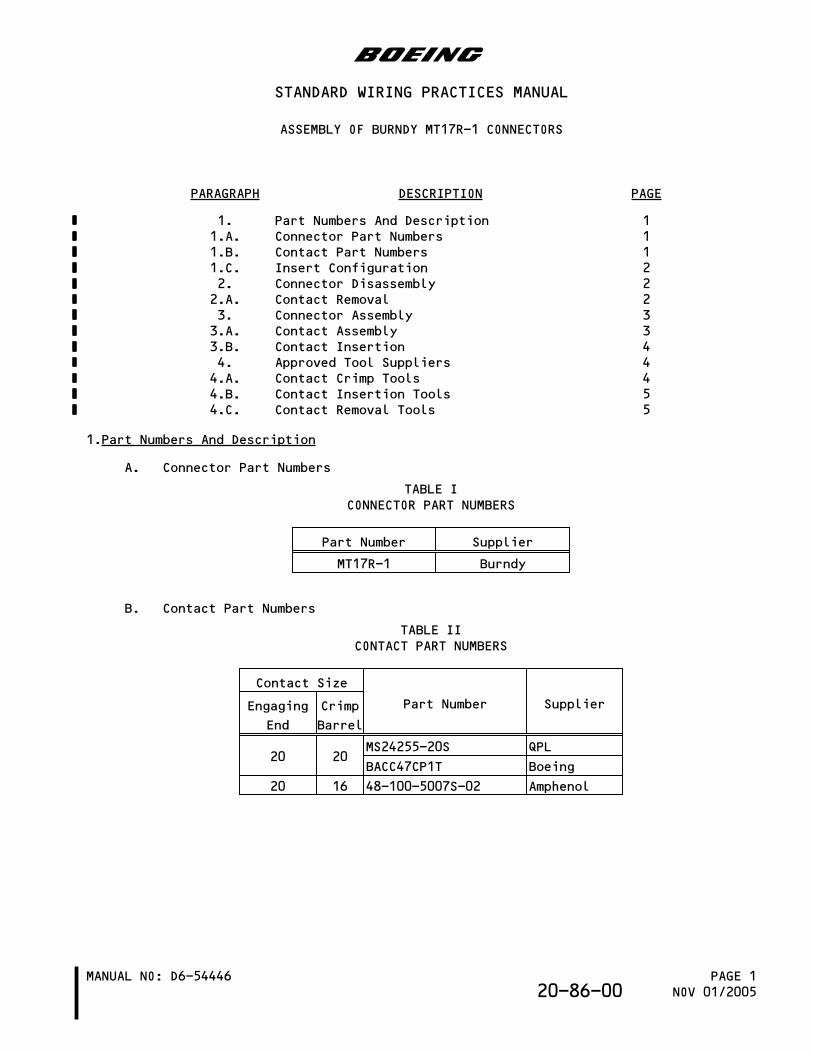
1.Part Numbers And Description
A. Connector Part Numbers
TABLE ICONNECTOR PART NUMBERS
Part Number Supplier
MT17R-1 Burndy
B. Contact Part Numbers
TABLE IICONTACT PART NUMBERS
Contact Size
Part Number SupplierEngaging
End
Crimp
Barrel
20 20MS24255-20S QPL
BACC47CP1T Boeing
20 16 48-100-5007S-02 Amphenol
b
STANDARD WIRING PRACTICES MANUAL
ASSEMBLY OF BURNDY MT17R-1 CONNECTORS
MANUAL NO: D6-54446 PAGE 1NOV 01/200520-86-00
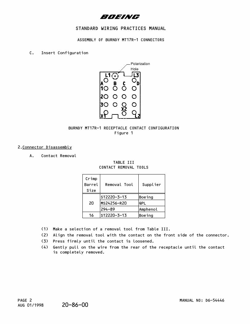
C. Insert Configuration
BURNDY MT17R-1 RECEPTACLE CONTACT CONFIGURATIONFigure 1
2.Connector Disassembly
A. Contact Removal
TABLE IIICONTACT REMOVAL TOOLS
Crimp
Barrel
Size
Removal Tool Supplier
20
ST2220-3-13 Boeing
MS24256-R20 QPL
294-89 Amphenol
16 ST2220-3-13 Boeing
(1) Make a selection of a removal tool from Table III.
(2) Align the removal tool with the contact on the front side of the connector.
(3) Press firmly until the contact is loosened.
(4) Gently pull on the wire from the rear of the receptacle until the contactis completely removed.
b
STANDARD WIRING PRACTICES MANUAL
ASSEMBLY OF BURNDY MT17R-1 CONNECTORS
MANUAL NO: D6-54446PAGE 2AUG 01/1998 20-86-00
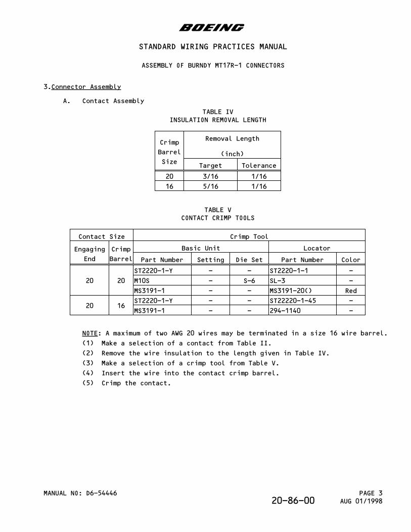
3.Connector Assembly
A. Contact Assembly
TABLE IVINSULATION REMOVAL LENGTH
Crimp
Barrel
Size
Removal Length
(inch)
Target Tolerance
20 3/16 1/16
16 5/16 1/16
TABLE VCONTACT CRIMP TOOLS
Contact Size Crimp Tool
Engaging
End
Crimp
Barrel
Basic Unit Locator
Part Number Setting Die Set Part Number Color
20 20
ST2220-1-Y - - ST2220-1-1 -
M10S - S-6 SL-3 -
MS3191-1 - - MS3191-20() Red
20 16ST2220-1-Y - - ST22220-1-45 -
MS3191-1 - - 294-1140 -
NOTE: A maximum of two AWG 20 wires may be terminated in a size 16 wire barrel.
(1) Make a selection of a contact from Table II.
(2) Remove the wire insulation to the length given in Table IV.
(3) Make a selection of a crimp tool from Table V.
(4) Insert the wire into the contact crimp barrel.
(5) Crimp the contact.
b
STANDARD WIRING PRACTICES MANUAL
ASSEMBLY OF BURNDY MT17R-1 CONNECTORS
MANUAL NO: D6-54446 PAGE 3AUG 01/199820-86-00
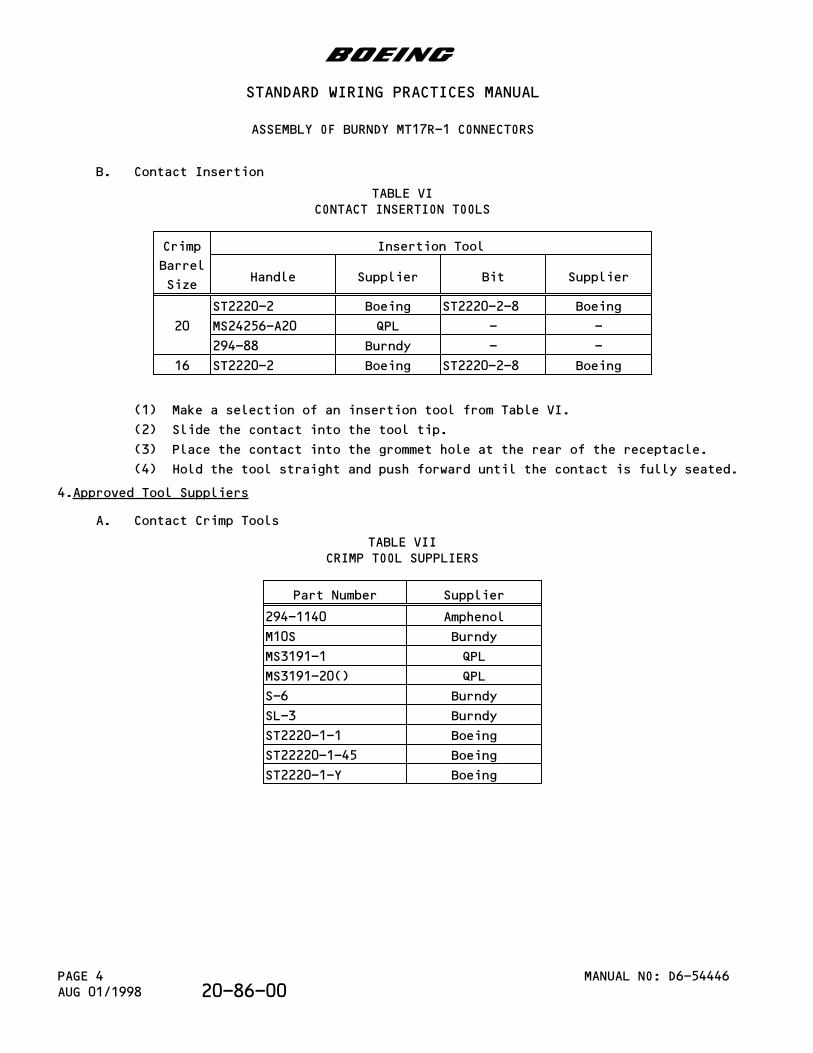
B. Contact Insertion
TABLE VICONTACT INSERTION TOOLS
Crimp
Barrel
Size
Insertion Tool
Handle Supplier Bit Supplier
20
ST2220-2 Boeing ST2220-2-8 Boeing
MS24256-A20 QPL - -
294-88 Burndy - -
16 ST2220-2 Boeing ST2220-2-8 Boeing
(1) Make a selection of an insertion tool from Table VI.
(2) Slide the contact into the tool tip.
(3) Place the contact into the grommet hole at the rear of the receptacle.
(4) Hold the tool straight and push forward until the contact is fully seated.
4.Approved Tool Suppliers
A. Contact Crimp Tools
TABLE VIICRIMP TOOL SUPPLIERS
Part Number Supplier
294-1140 Amphenol
M10S Burndy
MS3191-1 QPL
MS3191-20() QPL
S-6 Burndy
SL-3 Burndy
ST2220-1-1 Boeing
ST22220-1-45 Boeing
ST2220-1-Y Boeing
b
STANDARD WIRING PRACTICES MANUAL
ASSEMBLY OF BURNDY MT17R-1 CONNECTORS
MANUAL NO: D6-54446PAGE 4AUG 01/1998 20-86-00
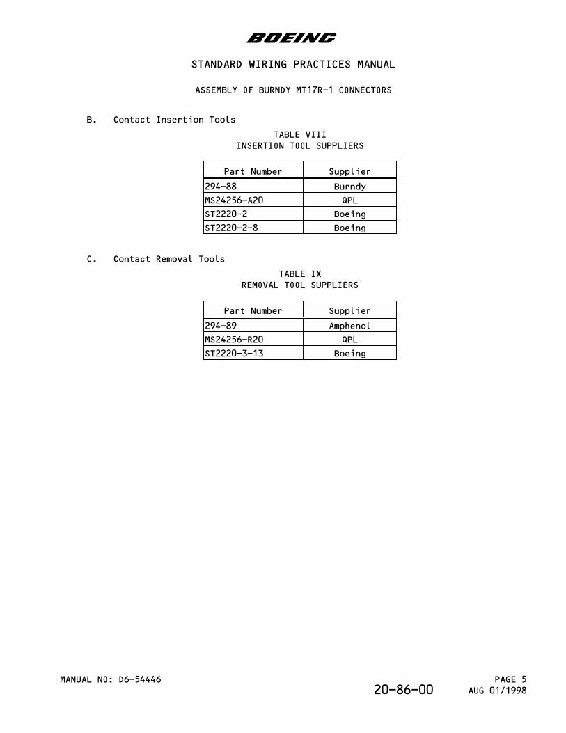
B. Contact Insertion Tools
TABLE VIIIINSERTION TOOL SUPPLIERS
Part Number Supplier
294-88 Burndy
MS24256-A20 QPL
ST2220-2 Boeing
ST2220-2-8 Boeing
C. Contact Removal Tools
TABLE IXREMOVAL TOOL SUPPLIERS
Part Number Supplier
294-89 Amphenol
MS24256-R20 QPL
ST2220-3-13 Boeing
b
STANDARD WIRING PRACTICES MANUAL
ASSEMBLY OF BURNDY MT17R-1 CONNECTORS
MANUAL NO: D6-54446 PAGE 5AUG 01/199820-86-00

This page is intentionally left blank
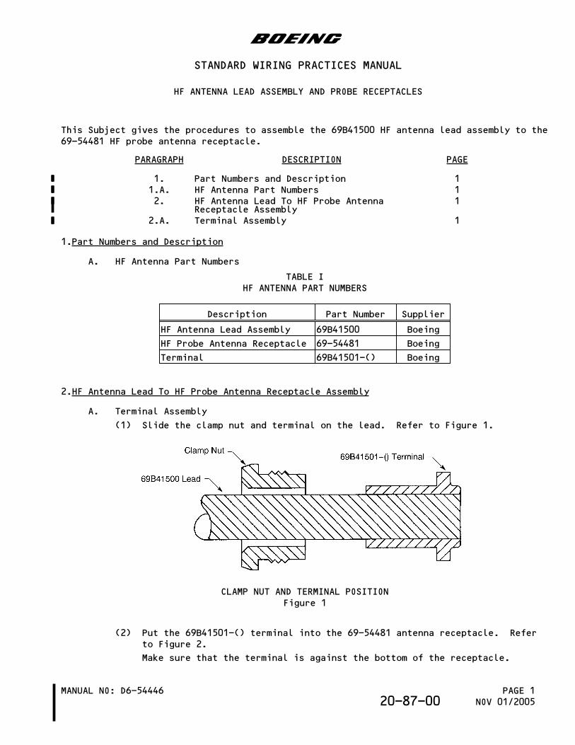
This Subject gives the procedures to assemble the 69B41500 HF antenna lead assembly to the69-54481 HF probe antenna receptacle.
PARAGRAPH DESCRIPTION PAGE
1. Part Numbers and Description 11.A. HF Antenna Part Numbers 12. HF Antenna Lead To HF Probe Antenna
Receptacle Assembly1
2.A. Terminal Assembly 1
1.Part Numbers and Description
A. HF Antenna Part Numbers
TABLE IHF ANTENNA PART NUMBERS
Description Part Number Supplier
HF Antenna Lead Assembly 69B41500 Boeing
HF Probe Antenna Receptacle 69-54481 Boeing
Terminal 69B41501-() Boeing
2.HF Antenna Lead To HF Probe Antenna Receptacle Assembly
A. Terminal Assembly
(1) Slide the clamp nut and terminal on the lead. Refer to Figure 1.
CLAMP NUT AND TERMINAL POSITIONFigure 1
(2) Put the 69B41501-() terminal into the 69-54481 antenna receptacle. Referto Figure 2.
Make sure that the terminal is against the bottom of the receptacle.
b
STANDARD WIRING PRACTICES MANUAL
HF ANTENNA LEAD ASSEMBLY AND PROBE RECEPTACLES
MANUAL NO: D6-54446 PAGE 1NOV 01/200520-87-00
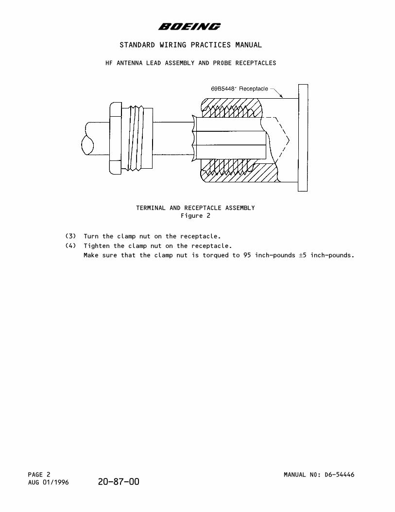
TERMINAL AND RECEPTACLE ASSEMBLYFigure 2
(3) Turn the clamp nut on the receptacle.
(4) Tighten the clamp nut on the receptacle.
Make sure that the clamp nut is torqued to 95 inch-pounds ±5 inch-pounds.
b
STANDARD WIRING PRACTICES MANUAL
HF ANTENNA LEAD ASSEMBLY AND PROBE RECEPTACLES
MANUAL NO: D6-54446PAGE 2AUG 01/1996 20-87-00
PARAGRAPH DESCRIPTION PAGE
1. Part Numbers and Description 11.A. Terminal Block Module Part Numbers 11.B. Resistor and Diode Terminal Block Part
Numbers4
1.C. Terminal Block Module Accessory PartNumbers
6
1.D. Contact Part Numbers for the StandardDensity Terminal Block
7
1.E. Contact Part Numbers for the High DensityTerminal Block
8
2. Terminal Block Module Location Codes 92.A. Terminal Block Module Identification 93. Terminal Block Module Removal 103.A. Removal of the Module from the Track 104. Terminal Block Module Disassembly 104.A. Contact Removal from Standard Density
Terminal Block Modules10
4.B. Contact Removal from High Density TerminalBlock Modules
12
5. Standard Density Terminal Block ModuleAssembly
12
5.A. Contact Assembly 125.B. Contact Insertion 156. High Density Terminal Block Module Assembly 166.A. Contact Assembly 166.B. Contact Insertion 177. Terminal Block Module Installation 177.A. Installation of the Module on the Track 17
1.Part Numbers and Description
A. Terminal Block Module Part Numbers
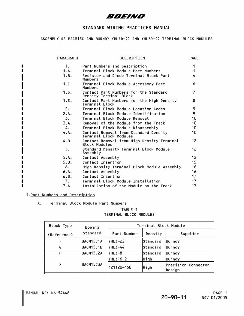
TABLE ITERMINAL BLOCK MODULES
Block Type
(Reference)
Boeing
Standard
Terminal Block Module
Part Number Density Supplier
F BACM15C1A YHLZ-22 Standard Burndy
G BACM15C1B YHLZ-44 Standard Burndy
H BACM15C2A YHLZ-8 Standard Burndy
X BACM15C3A
YHLZ16-2 High Burndy
421120-450 HighPrecision ConnectorDesign
b
STANDARD WIRING PRACTICES MANUAL
ASSEMBLY OF BACM15C AND BURNDY YHLZD-() AND YHLZR-() TERMINAL BLOCK MODULES
MANUAL NO: D6-54446 PAGE 1NOV 01/200520-90-11
Block Type
(Reference)
Boeing
Standard
Terminal Block Module
Part Number Density Supplier
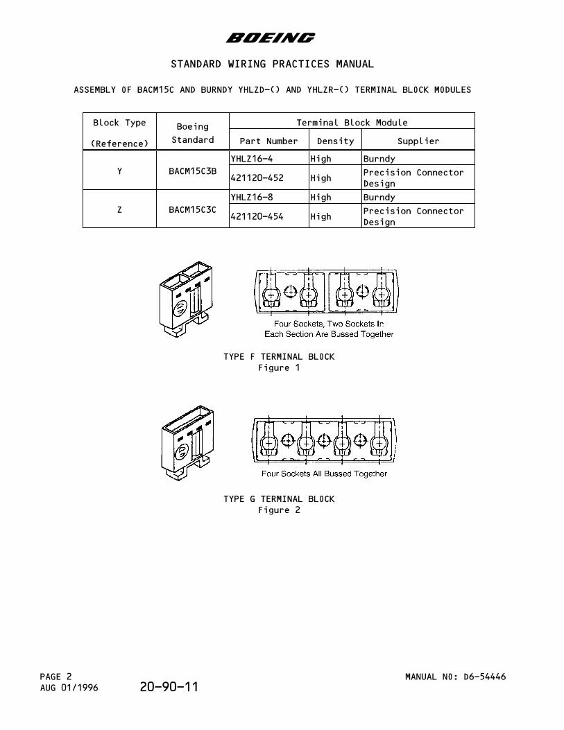
Y BACM15C3B
YHLZ16-4 High Burndy
421120-452 HighPrecision ConnectorDesign
Z BACM15C3C
YHLZ16-8 High Burndy
421120-454 HighPrecision ConnectorDesign
TYPE F TERMINAL BLOCKFigure 1
TYPE G TERMINAL BLOCKFigure 2
b
STANDARD WIRING PRACTICES MANUAL
ASSEMBLY OF BACM15C AND BURNDY YHLZD-() AND YHLZR-() TERMINAL BLOCK MODULES
MANUAL NO: D6-54446PAGE 2AUG 01/1996 20-90-11
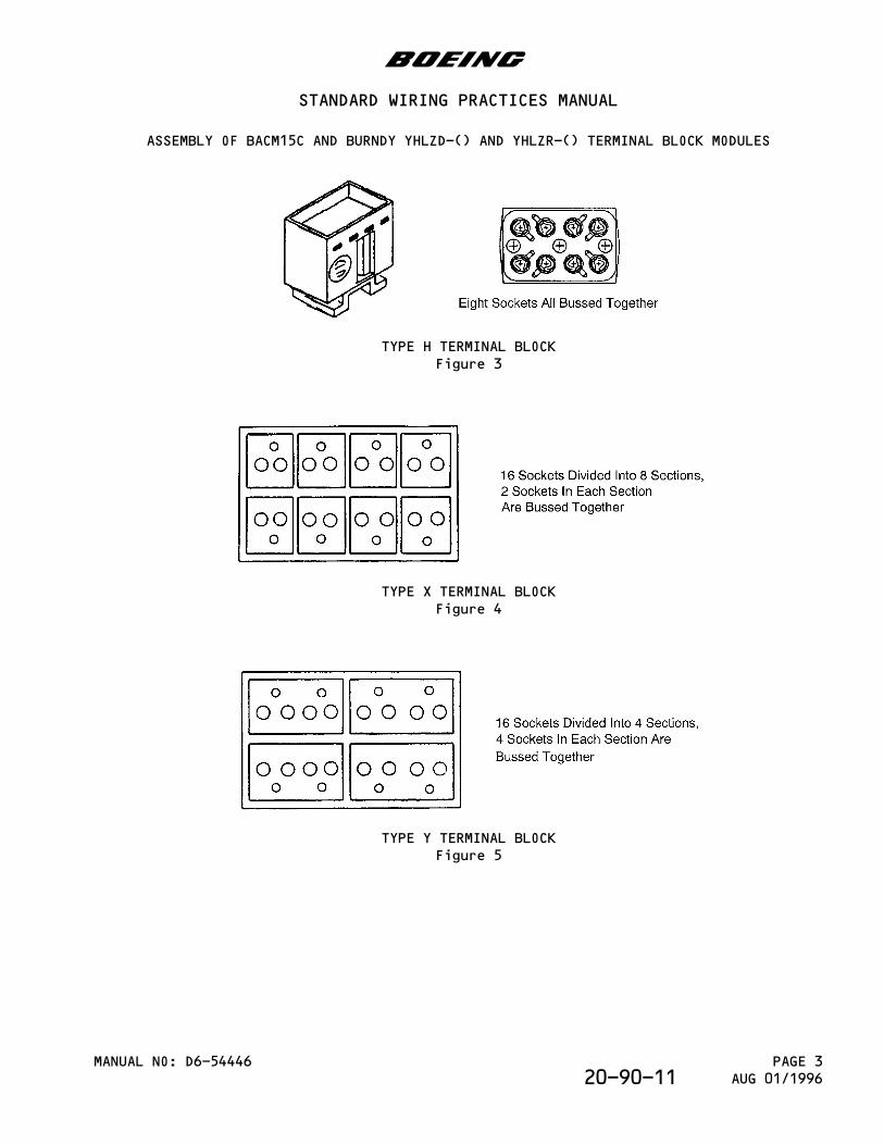
TYPE H TERMINAL BLOCKFigure 3
TYPE X TERMINAL BLOCKFigure 4
TYPE Y TERMINAL BLOCKFigure 5
b
STANDARD WIRING PRACTICES MANUAL
ASSEMBLY OF BACM15C AND BURNDY YHLZD-() AND YHLZR-() TERMINAL BLOCK MODULES
MANUAL NO: D6-54446 PAGE 3AUG 01/199620-90-11
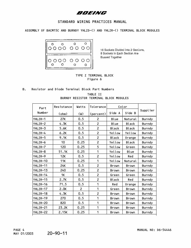
TYPE Z TERMINAL BLOCKFigure 6
B. Resistor and Diode Terminal Block Part Numbers
TABLE IIBURNDY RESISTOR TERMINAL BLOCK MODULES
Part
Number
Resistance
(ohm)
Watts
(W)
Tolerance
(percent)
ColorSupplier
Side A Side B
YHLZR-1 27K 0.5 2 Blue Natural Burndy
YHLZR-2 4.3K 0.5 2 Blue Black Burndy
YHLZR-3 5.6K 0.5 2 Black Black Burndy
YHLZR-4 6.2K 0.5 2 Yellow Yellow Burndy
YHLZR-5 9.1K 0.5 2 Black Orange Burndy
YHLZR-6 10 0.25 2 Yellow Black Burndy
YHLZR-7 120 0.25 5 Yellow Green Burndy
YHLZR-8 51.1K 0.25 1 Yellow Blue Burndy
YHLZR-9 12K 0.5 2 Yellow Red Burndy
YHLZR-10 11K 0.25 1 Yellow Natural Burndy
YHLZR-11 24K 0.5 2 Brown Brown Burndy
YHLZR-13 240 0.25 2 Brown Brown Burndy
YHLZR-14 1K 0.5 2 Green Green Burndy
YHLZR-15 2.7K 0.5 2 Black Red Burndy
YHLZR-16 71.5 0.5 1 Red Orange Burndy
YHLZR-17 2.0K 2 1 Green Brown Burndy
YHLZR-18 4.3K 0.5 2 Brown Brown Burndy
YHLZR-19 270 0.5 1 Brown Brown Burndy
YHLZR-20 820 0.5 1 Brown Brown Burndy
YHLZR-21 23.2K 0.25 1 Brown Brown Burndy
YHLZR-22 2.15K 0.25 1 Brown Brown Burndy
b
STANDARD WIRING PRACTICES MANUAL
ASSEMBLY OF BACM15C AND BURNDY YHLZD-() AND YHLZR-() TERMINAL BLOCK MODULES
MANUAL NO: D6-54446PAGE 4MAY 01/2003 20-90-11
Part
Number
Resistance
(ohm)
Watts
(W)
Tolerance
(percent)
ColorSupplier
Side A Side B
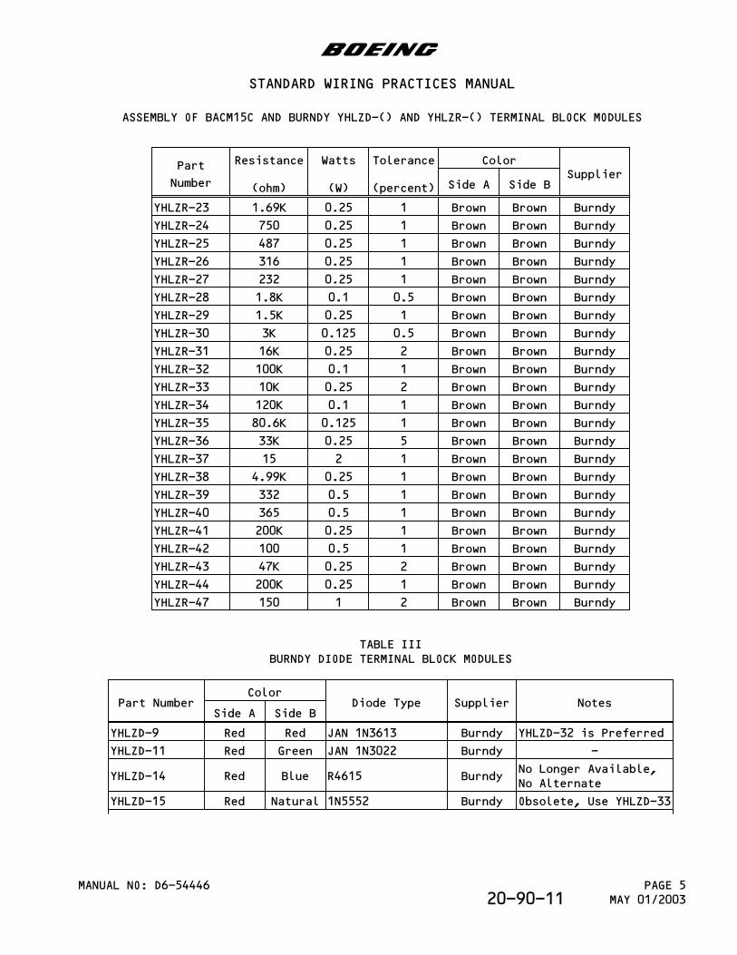
YHLZR-23 1.69K 0.25 1 Brown Brown Burndy
YHLZR-24 750 0.25 1 Brown Brown Burndy
YHLZR-25 487 0.25 1 Brown Brown Burndy
YHLZR-26 316 0.25 1 Brown Brown Burndy
YHLZR-27 232 0.25 1 Brown Brown Burndy
YHLZR-28 1.8K 0.1 0.5 Brown Brown Burndy
YHLZR-29 1.5K 0.25 1 Brown Brown Burndy
YHLZR-30 3K 0.125 0.5 Brown Brown Burndy
YHLZR-31 16K 0.25 2 Brown Brown Burndy
YHLZR-32 100K 0.1 1 Brown Brown Burndy
YHLZR-33 10K 0.25 2 Brown Brown Burndy
YHLZR-34 120K 0.1 1 Brown Brown Burndy
YHLZR-35 80.6K 0.125 1 Brown Brown Burndy
YHLZR-36 33K 0.25 5 Brown Brown Burndy
YHLZR-37 15 2 1 Brown Brown Burndy
YHLZR-38 4.99K 0.25 1 Brown Brown Burndy
YHLZR-39 332 0.5 1 Brown Brown Burndy
YHLZR-40 365 0.5 1 Brown Brown Burndy
YHLZR-41 200K 0.25 1 Brown Brown Burndy
YHLZR-42 100 0.5 1 Brown Brown Burndy
YHLZR-43 47K 0.25 2 Brown Brown Burndy
YHLZR-44 200K 0.25 1 Brown Brown Burndy
YHLZR-47 150 1 2 Brown Brown Burndy
TABLE IIIBURNDY DIODE TERMINAL BLOCK MODULES
Part NumberColor
Diode Type Supplier NotesSide A Side B
YHLZD-9 Red Red JAN 1N3613 Burndy YHLZD-32 is Preferred
YHLZD-11 Red Green JAN 1N3022 Burndy -
YHLZD-14 Red Blue R4615 BurndyNo Longer Available,No Alternate
YHLZD-15 Red Natural 1N5552 Burndy Obsolete, Use YHLZD-33
b
STANDARD WIRING PRACTICES MANUAL
ASSEMBLY OF BACM15C AND BURNDY YHLZD-() AND YHLZR-() TERMINAL BLOCK MODULES
MANUAL NO: D6-54446 PAGE 5MAY 01/200320-90-11
Part NumberColor
Diode Type Supplier NotesSide A Side B
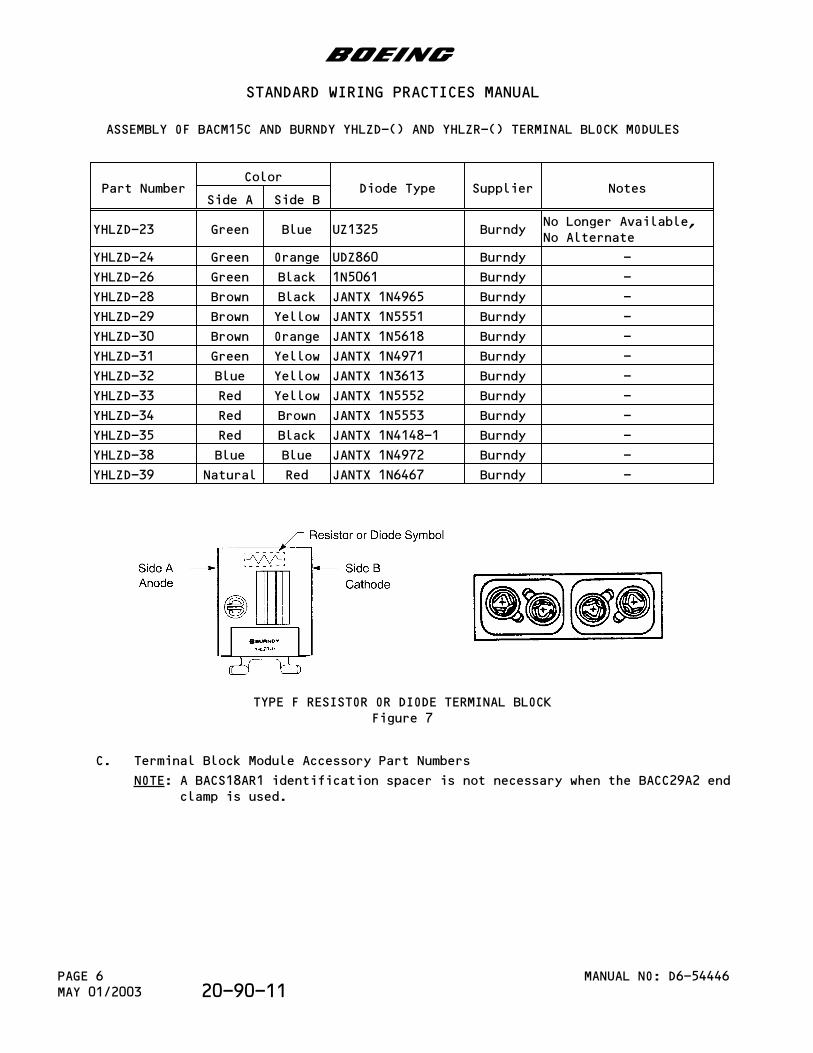
YHLZD-23 Green Blue UZ1325 BurndyNo Longer Available,No Alternate
YHLZD-24 Green Orange UDZ860 Burndy -
YHLZD-26 Green Black 1N5061 Burndy -
YHLZD-28 Brown Black JANTX 1N4965 Burndy -
YHLZD-29 Brown Yellow JANTX 1N5551 Burndy -
YHLZD-30 Brown Orange JANTX 1N5618 Burndy -
YHLZD-31 Green Yellow JANTX 1N4971 Burndy -
YHLZD-32 Blue Yellow JANTX 1N3613 Burndy -
YHLZD-33 Red Yellow JANTX 1N5552 Burndy -
YHLZD-34 Red Brown JANTX 1N5553 Burndy -
YHLZD-35 Red Black JANTX 1N4148-1 Burndy -
YHLZD-38 Blue Blue JANTX 1N4972 Burndy -
YHLZD-39 Natural Red JANTX 1N6467 Burndy -
TYPE F RESISTOR OR DIODE TERMINAL BLOCKFigure 7
C. Terminal Block Module Accessory Part Numbers
NOTE: A BACS18AR1 identification spacer is not necessary when the BACC29A2 endclamp is used.
b
STANDARD WIRING PRACTICES MANUAL
ASSEMBLY OF BACM15C AND BURNDY YHLZD-() AND YHLZR-() TERMINAL BLOCK MODULES
MANUAL NO: D6-54446PAGE 6MAY 01/2003 20-90-11
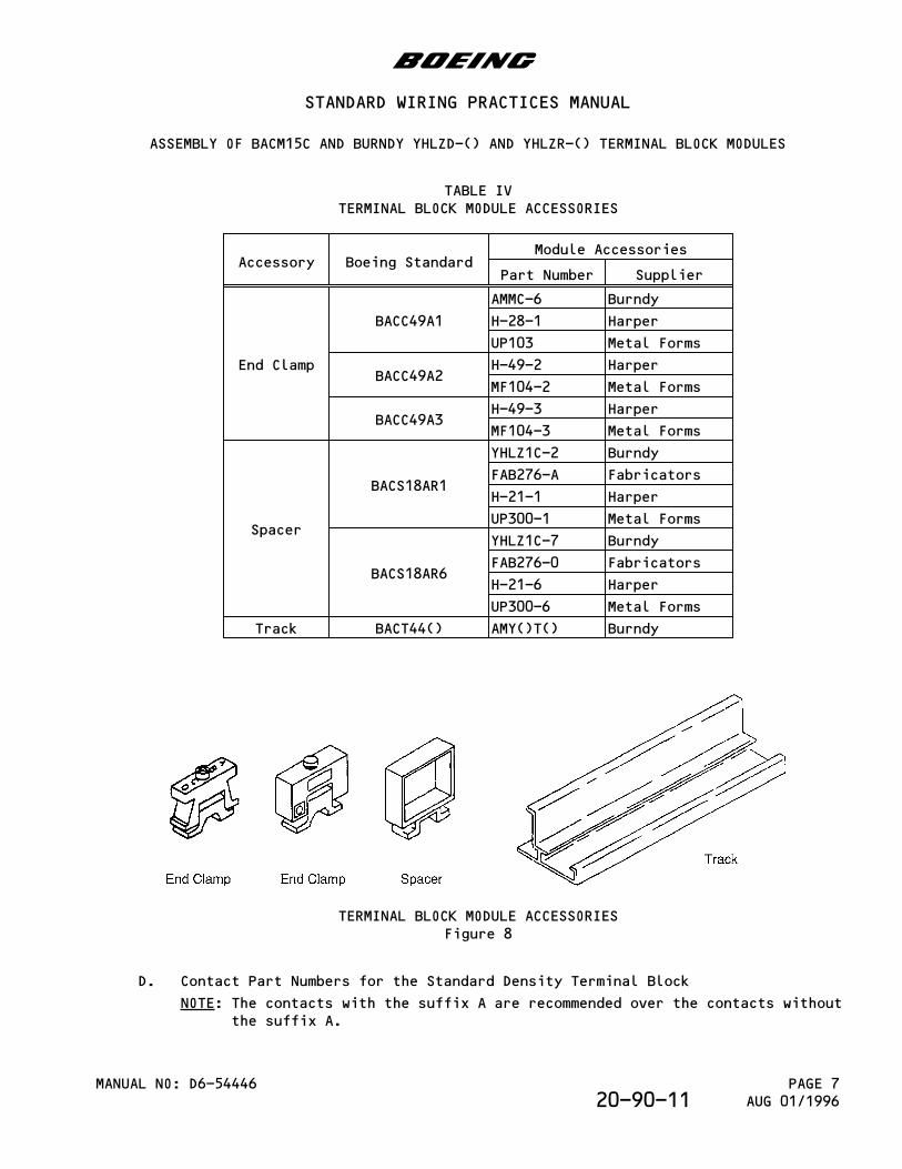
TABLE IVTERMINAL BLOCK MODULE ACCESSORIES
Accessory Boeing StandardModule Accessories
Part Number Supplier
End Clamp
BACC49A1
AMMC-6 Burndy
H-28-1 Harper
UP103 Metal Forms
BACC49A2H-49-2 Harper
MF104-2 Metal Forms
BACC49A3H-49-3 Harper
MF104-3 Metal Forms
Spacer
BACS18AR1
YHLZ1C-2 Burndy
FAB276-A Fabricators
H-21-1 Harper
UP300-1 Metal Forms
BACS18AR6
YHLZ1C-7 Burndy
FAB276-0 Fabricators
H-21-6 Harper
UP300-6 Metal Forms
Track BACT44() AMY()T() Burndy
TERMINAL BLOCK MODULE ACCESSORIESFigure 8
D. Contact Part Numbers for the Standard Density Terminal Block
NOTE: The contacts with the suffix A are recommended over the contacts withoutthe suffix A.
b
STANDARD WIRING PRACTICES MANUAL
ASSEMBLY OF BACM15C AND BURNDY YHLZD-() AND YHLZR-() TERMINAL BLOCK MODULES
MANUAL NO: D6-54446 PAGE 7AUG 01/199620-90-11
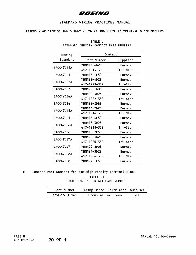
TABLE VSTANDARD DENSITY CONTACT PART NUMBERS
Boeing
Standard
Contact
Part Number Supplier
BACC47DE1AYHMM16-6D28 Burndy
417-1215-332 Tri-Star
BACC47DE1 YHMM16-1F50 Burndy
BACC47DE3AYHMM22-4D28 Burndy
417-1223-332 Tri-Star
BACC47DE3 YHMM22-1DB8 Burndy
BACC47DE4AYHMM22-5D28 Burndy
417-1222-332 Tri-Star
BACC47DE4 YHMM22-2DB8 Burndy
BACC47DE5AYHMM16-7D28 Burndy
417-1216-332 Tri-Star
BACC47DE5 YHMM16-4F50 Burndy
BACC47DE6AYHMM18-3D28 Burndy
417-1218-332 Tri-Star
BACC47DE6 YHMM18-2F50 Burndy
BACC47DE7AYHMM20-3D28 Burndy
417-1220-332 Tri-Star
BACC47DE7 YHMM20-2DB8 Burndy
BACC47DE8AYHMM24-3D28 Burndy
417-1224-332 Tri-Star
BACC47DE8 YHMM24-1F50 Burndy
E. Contact Part Numbers for the High Density Terminal Block
TABLE VIHIGH DENSITY CONTACT PART NUMBERS
Part Number Crimp Barrel Color Code Supplier
M39029/11-145 Brown Yellow Green QPL
b
STANDARD WIRING PRACTICES MANUAL
ASSEMBLY OF BACM15C AND BURNDY YHLZD-() AND YHLZR-() TERMINAL BLOCK MODULES
MANUAL NO: D6-54446PAGE 8AUG 01/1996 20-90-11
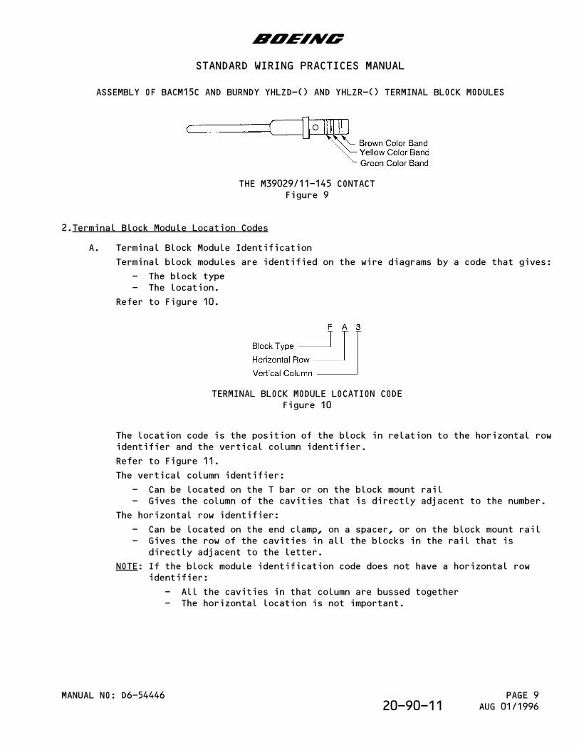
THE M39029/11-145 CONTACTFigure 9
2.Terminal Block Module Location Codes
A. Terminal Block Module Identification
Terminal block modules are identified on the wire diagrams by a code that gives:
- The block type- The location.
Refer to Figure 10.
TERMINAL BLOCK MODULE LOCATION CODEFigure 10
The location code is the position of the block in relation to the horizontal rowidentifier and the vertical column identifier.
Refer to Figure 11.
The vertical column identifier:
- Can be located on the T bar or on the block mount rail- Gives the column of the cavities that is directly adjacent to the number.
The horizontal row identifier:
- Can be located on the end clamp, on a spacer, or on the block mount rail- Gives the row of the cavities in all the blocks in the rail that is
directly adjacent to the letter.
NOTE: If the block module identification code does not have a horizontal rowidentifier:
- All the cavities in that column are bussed together- The horizontal location is not important.
b
STANDARD WIRING PRACTICES MANUAL
ASSEMBLY OF BACM15C AND BURNDY YHLZD-() AND YHLZR-() TERMINAL BLOCK MODULES
MANUAL NO: D6-54446 PAGE 9AUG 01/199620-90-11
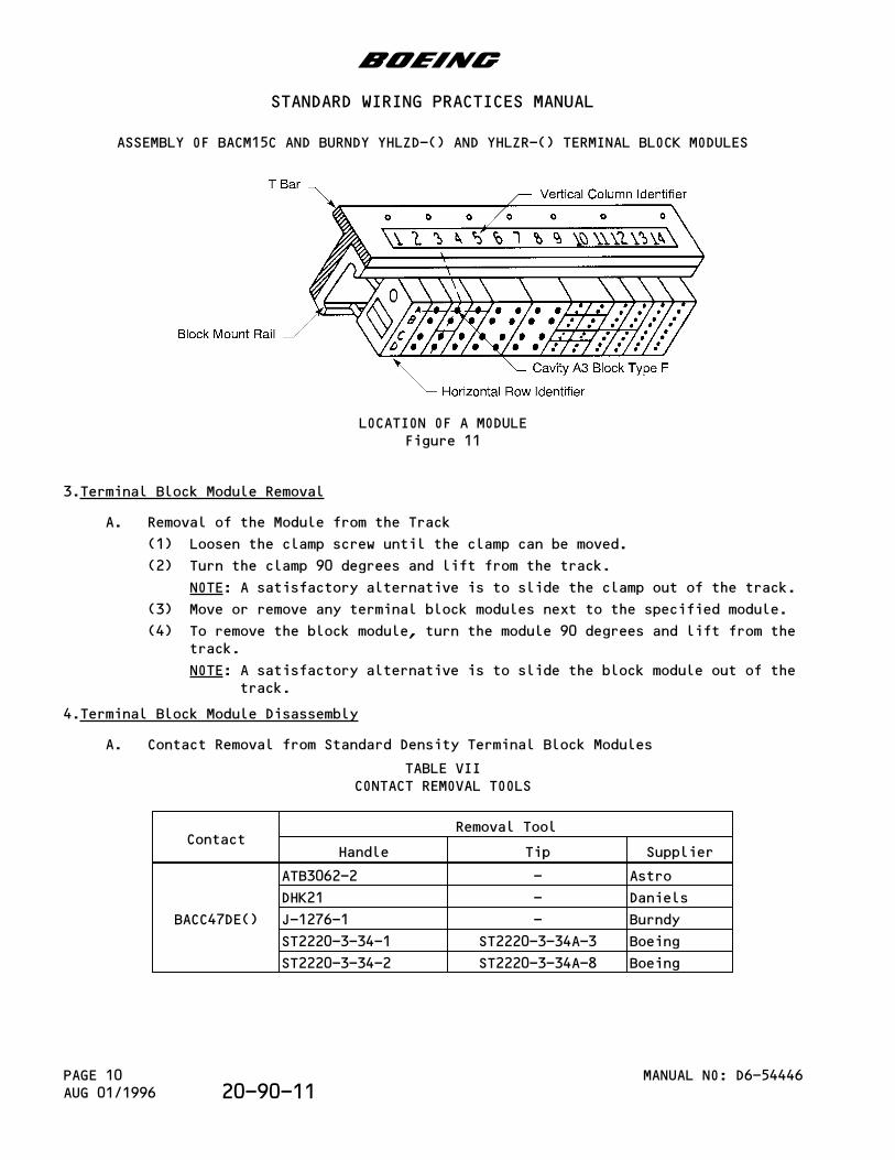
LOCATION OF A MODULEFigure 11
3.Terminal Block Module Removal
A. Removal of the Module from the Track
(1) Loosen the clamp screw until the clamp can be moved.
(2) Turn the clamp 90 degrees and lift from the track.
NOTE: A satisfactory alternative is to slide the clamp out of the track.
(3) Move or remove any terminal block modules next to the specified module.
(4) To remove the block module, turn the module 90 degrees and lift from thetrack.
NOTE: A satisfactory alternative is to slide the block module out of thetrack.
4.Terminal Block Module Disassembly
A. Contact Removal from Standard Density Terminal Block Modules
TABLE VIICONTACT REMOVAL TOOLS
ContactRemoval Tool
Handle Tip Supplier
BACC47DE()
ATB3062-2 - Astro
DHK21 - Daniels
J-1276-1 - Burndy
ST2220-3-34-1 ST2220-3-34A-3 Boeing
ST2220-3-34-2 ST2220-3-34A-8 Boeing
b
STANDARD WIRING PRACTICES MANUAL
ASSEMBLY OF BACM15C AND BURNDY YHLZD-() AND YHLZR-() TERMINAL BLOCK MODULES
MANUAL NO: D6-54446PAGE 10AUG 01/1996 20-90-11
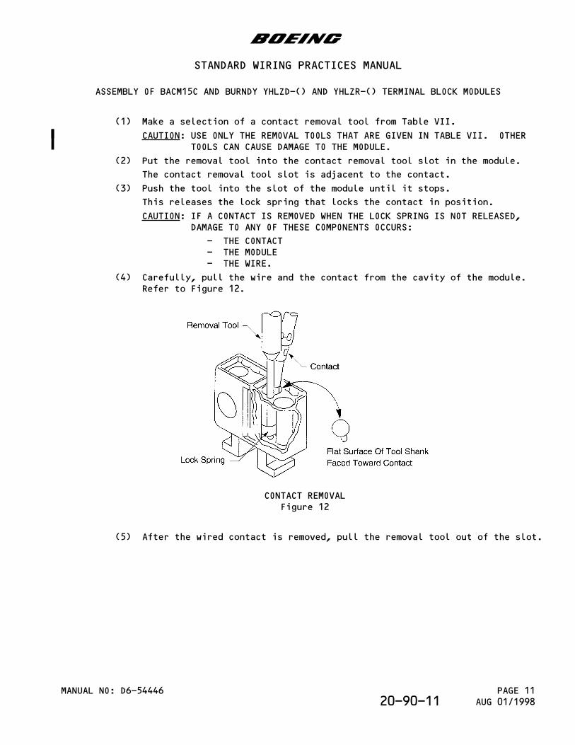
(1) Make a selection of a contact removal tool from Table VII.
CAUTION: USE ONLY THE REMOVAL TOOLS THAT ARE GIVEN IN TABLE VII. OTHERTOOLS CAN CAUSE DAMAGE TO THE MODULE.
(2) Put the removal tool into the contact removal tool slot in the module.
The contact removal tool slot is adjacent to the contact.
(3) Push the tool into the slot of the module until it stops.
This releases the lock spring that locks the contact in position.
CAUTION: IF A CONTACT IS REMOVED WHEN THE LOCK SPRING IS NOT RELEASED,DAMAGE TO ANY OF THESE COMPONENTS OCCURS:
- THE CONTACT- THE MODULE- THE WIRE.
(4) Carefully, pull the wire and the contact from the cavity of the module.Refer to Figure 12.
CONTACT REMOVALFigure 12
(5) After the wired contact is removed, pull the removal tool out of the slot.
b
STANDARD WIRING PRACTICES MANUAL
ASSEMBLY OF BACM15C AND BURNDY YHLZD-() AND YHLZR-() TERMINAL BLOCK MODULES
MANUAL NO: D6-54446 PAGE 11AUG 01/199820-90-11
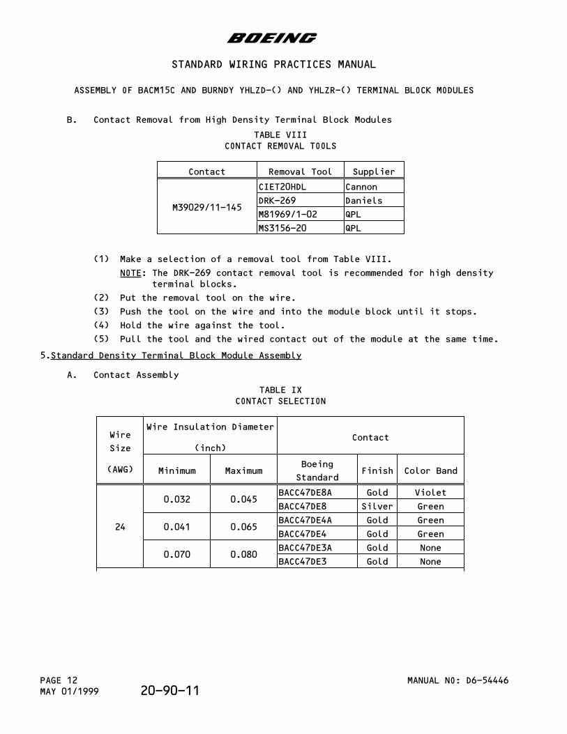
B. Contact Removal from High Density Terminal Block Modules
TABLE VIIICONTACT REMOVAL TOOLS
Contact Removal Tool Supplier
M39029/11-145
CIET20HDL Cannon
DRK-269 Daniels
M81969/1-02 QPL
MS3156-20 QPL
(1) Make a selection of a removal tool from Table VIII.
NOTE: The DRK-269 contact removal tool is recommended for high densityterminal blocks.
(2) Put the removal tool on the wire.
(3) Push the tool on the wire and into the module block until it stops.
(4) Hold the wire against the tool.
(5) Pull the tool and the wired contact out of the module at the same time.
5.Standard Density Terminal Block Module Assembly
A. Contact Assembly
TABLE IXCONTACT SELECTION
Wire
Size
(AWG)
Wire Insulation Diameter
(inch)Contact
Minimum MaximumBoeing
StandardFinish Color Band
24
0.032 0.045BACC47DE8A Gold Violet
BACC47DE8 Silver Green
0.041 0.065BACC47DE4A Gold Green
BACC47DE4 Gold Green
0.070 0.080BACC47DE3A Gold None
BACC47DE3 Gold None
b
STANDARD WIRING PRACTICES MANUAL
ASSEMBLY OF BACM15C AND BURNDY YHLZD-() AND YHLZR-() TERMINAL BLOCK MODULES
MANUAL NO: D6-54446PAGE 12MAY 01/1999 20-90-11
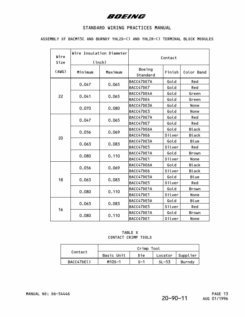
Wire
Size
(AWG)
Wire Insulation Diameter
(inch)Contact
Minimum MaximumBoeing
StandardFinish Color Band
22
0.047 0.065BACC47DE7A Gold Red
BACC47DE7 Gold Red
0.041 0.065BACC47DE4A Gold Green
BACC47DE4 Gold Green
0.070 0.080BACC47DE3A Gold None
BACC47DE3 Gold None
20
0.047 0.065BACC47DE7A Gold Red
BACC47DE7 Gold Red
0.056 0.069BACC47DE6A Gold Black
BACC47DE6 Silver Black
0.063 0.083BACC47DE5A Gold Blue
BACC47DE5 Silver Red
0.080 0.110BACC47DE1A Gold Brown
BACC47DE1 Silver None
18
0.056 0.069BACC47DE6A Gold Black
BACC47DE6 Silver Black
0.063 0.083BACC47DE5A Gold Blue
BACC47DE5 Silver Red
0.080 0.110BACC47DE1A Gold Brown
BACC47DE1 Silver None
16
0.063 0.083BACC47DE5A Gold Blue
BACC47DE5 Silver Red
0.080 0.110BACC47DE1A Gold Brown
BACC47DE1 Silver None
TABLE XCONTACT CRIMP TOOLS
ContactCrimp Tool
Basic Unit Die Locator Supplier
BACC47DE() M10S-1 S-1 SL-53 Burndy
b
STANDARD WIRING PRACTICES MANUAL
ASSEMBLY OF BACM15C AND BURNDY YHLZD-() AND YHLZR-() TERMINAL BLOCK MODULES
MANUAL NO: D6-54446 PAGE 13AUG 01/199620-90-11
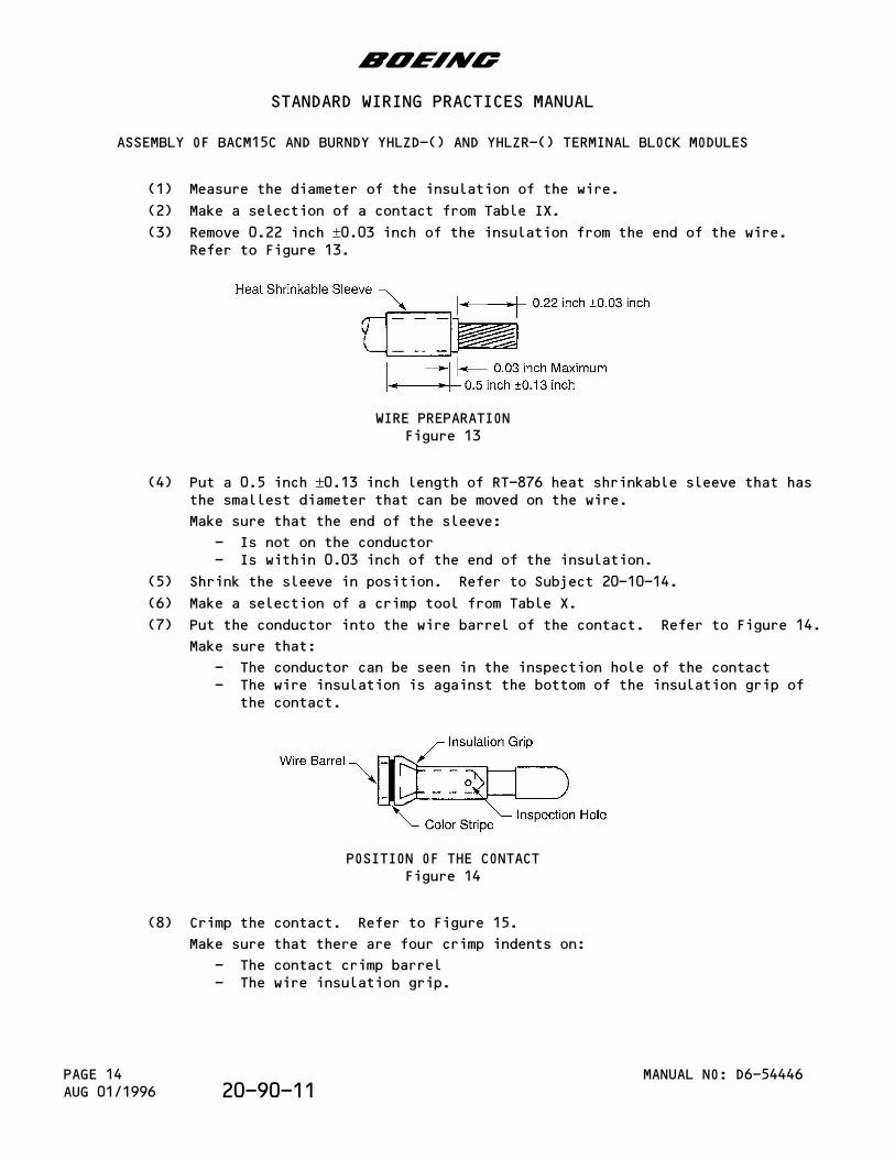
(1) Measure the diameter of the insulation of the wire.
(2) Make a selection of a contact from Table IX.
(3) Remove 0.22 inch ±0.03 inch of the insulation from the end of the wire.Refer to Figure 13.
WIRE PREPARATIONFigure 13
(4) Put a 0.5 inch ±0.13 inch length of RT-876 heat shrinkable sleeve that hasthe smallest diameter that can be moved on the wire.
Make sure that the end of the sleeve:
- Is not on the conductor- Is within 0.03 inch of the end of the insulation.
(5) Shrink the sleeve in position. Refer to Subject 20-10-14.
(6) Make a selection of a crimp tool from Table X.
(7) Put the conductor into the wire barrel of the contact. Refer to Figure 14.
Make sure that:
- The conductor can be seen in the inspection hole of the contact- The wire insulation is against the bottom of the insulation grip of
the contact.
POSITION OF THE CONTACTFigure 14
(8) Crimp the contact. Refer to Figure 15.
Make sure that there are four crimp indents on:
- The contact crimp barrel- The wire insulation grip.
b
STANDARD WIRING PRACTICES MANUAL
ASSEMBLY OF BACM15C AND BURNDY YHLZD-() AND YHLZR-() TERMINAL BLOCK MODULES
MANUAL NO: D6-54446PAGE 14AUG 01/1996 20-90-11
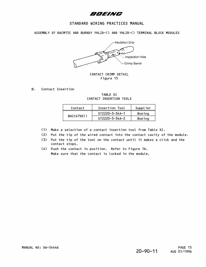
CONTACT CRIMP DETAILFigure 15
B. Contact Insertion
TABLE XICONTACT INSERTION TOOLS
Contact Insertion Tool Supplier
BACC47DE()ST2220-3-34A-1 Boeing
ST2220-3-34A-2 Boeing
(1) Make a selection of a contact insertion tool from Table XI.
(2) Put the tip of the wired contact into the contact cavity of the module.
(3) Put the tip of the tool on the contact until it makes a click and thecontact stops.
(4) Push the contact in position. Refer to Figure 16.
Make sure that the contact is locked in the module.
b
STANDARD WIRING PRACTICES MANUAL
ASSEMBLY OF BACM15C AND BURNDY YHLZD-() AND YHLZR-() TERMINAL BLOCK MODULES
MANUAL NO: D6-54446 PAGE 15AUG 01/199620-90-11
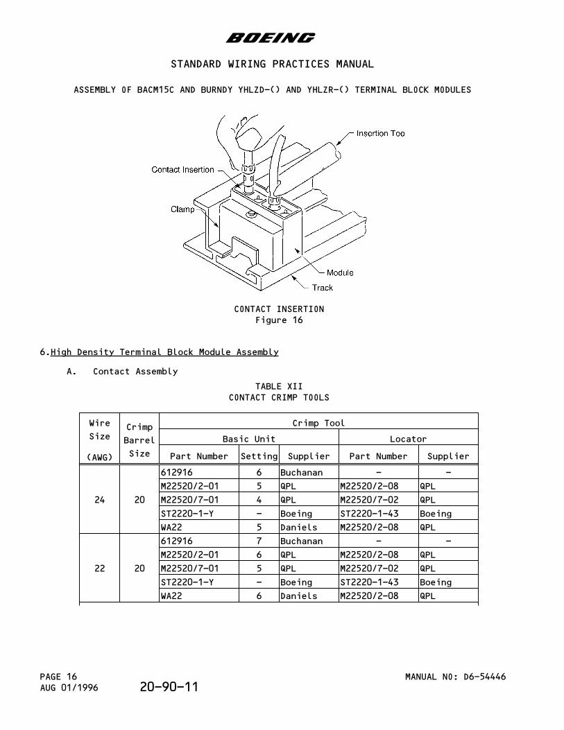
CONTACT INSERTIONFigure 16
6.High Density Terminal Block Module Assembly
A. Contact Assembly
TABLE XIICONTACT CRIMP TOOLS
Wire
Size
(AWG)
Crimp
Barrel
Size
Crimp Tool
Basic Unit Locator
Part Number Setting Supplier Part Number Supplier
24 20
612916 6 Buchanan - -
M22520/2-01 5 QPL M22520/2-08 QPL
M22520/7-01 4 QPL M22520/7-02 QPL
ST2220-1-Y - Boeing ST2220-1-43 Boeing
WA22 5 Daniels M22520/2-08 QPL
22 20
612916 7 Buchanan - -
M22520/2-01 6 QPL M22520/2-08 QPL
M22520/7-01 5 QPL M22520/7-02 QPL
ST2220-1-Y - Boeing ST2220-1-43 Boeing
WA22 6 Daniels M22520/2-08 QPL
b
STANDARD WIRING PRACTICES MANUAL
ASSEMBLY OF BACM15C AND BURNDY YHLZD-() AND YHLZR-() TERMINAL BLOCK MODULES
MANUAL NO: D6-54446PAGE 16AUG 01/1996 20-90-11
Wire
Size
(AWG)
Crimp
Barrel
Size
Crimp Tool
Basic Unit Locator
Part Number Setting Supplier Part Number Supplier
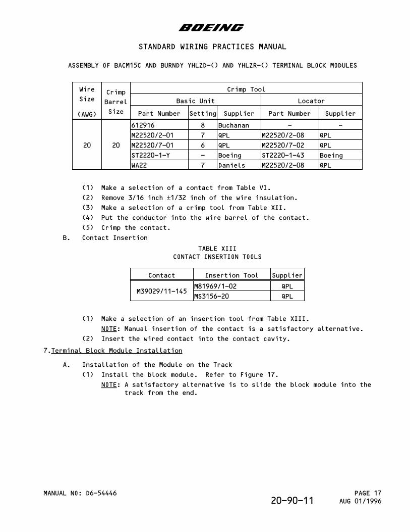
20 20
612916 8 Buchanan - -
M22520/2-01 7 QPL M22520/2-08 QPL
M22520/7-01 6 QPL M22520/7-02 QPL
ST2220-1-Y - Boeing ST2220-1-43 Boeing
WA22 7 Daniels M22520/2-08 QPL
(1) Make a selection of a contact from Table VI.
(2) Remove 3/16 inch ±1/32 inch of the wire insulation.(3) Make a selection of a crimp tool from Table XII.
(4) Put the conductor into the wire barrel of the contact.
(5) Crimp the contact.
B. Contact Insertion
TABLE XIIICONTACT INSERTION TOOLS
Contact Insertion Tool Supplier
M39029/11-145M81969/1-02 QPL
MS3156-20 QPL
(1) Make a selection of an insertion tool from Table XIII.
NOTE: Manual insertion of the contact is a satisfactory alternative.
(2) Insert the wired contact into the contact cavity.
7.Terminal Block Module Installation
A. Installation of the Module on the Track
(1) Install the block module. Refer to Figure 17.
NOTE: A satisfactory alternative is to slide the block module into thetrack from the end.
b
STANDARD WIRING PRACTICES MANUAL
ASSEMBLY OF BACM15C AND BURNDY YHLZD-() AND YHLZR-() TERMINAL BLOCK MODULES
MANUAL NO: D6-54446 PAGE 17AUG 01/199620-90-11
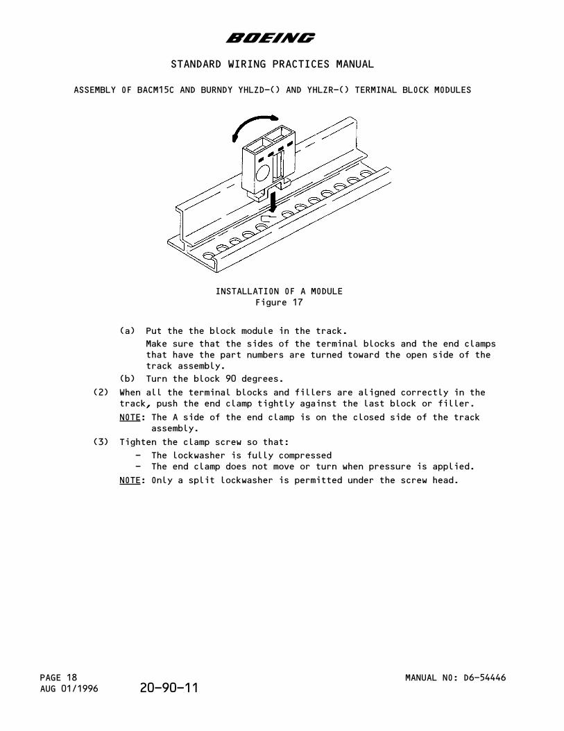
INSTALLATION OF A MODULEFigure 17
(a) Put the the block module in the track.
Make sure that the sides of the terminal blocks and the end clampsthat have the part numbers are turned toward the open side of thetrack assembly.
(b) Turn the block 90 degrees.
(2) When all the terminal blocks and fillers are aligned correctly in thetrack, push the end clamp tightly against the last block or filler.
NOTE: The A side of the end clamp is on the closed side of the trackassembly.
(3) Tighten the clamp screw so that:
- The lockwasher is fully compressed- The end clamp does not move or turn when pressure is applied.
NOTE: Only a split lockwasher is permitted under the screw head.
b
STANDARD WIRING PRACTICES MANUAL
ASSEMBLY OF BACM15C AND BURNDY YHLZD-() AND YHLZR-() TERMINAL BLOCK MODULES
MANUAL NO: D6-54446PAGE 18AUG 01/1996 20-90-11
PARAGRAPH DESCRIPTION PAGE
1. Part Numbers and Description 11.A. Terminal Block Part Numbers 11.B. Contact Part Numbers 21.C. Seal Plug Part Numbers 21.D. Terminal Block Mounting Track Part Number 32. Terminal Block Disassembly 32.A. Terminal Block Removal 32.B. Contact Removal 33. Terminal Block Assembly 33.A. Contact Assembly 33.B. Contact Insertion 43.C. Seal Plug Installation 43.D. Terminal Block Installation 5
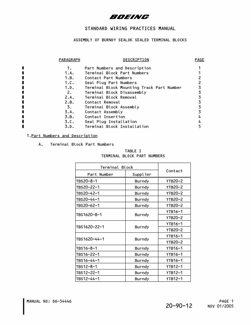
1.Part Numbers and Description
A. Terminal Block Part Numbers
TABLE ITERMINAL BLOCK PART NUMBERS
Terminal BlockContact
Part Number Supplier
TBS20-8-1 Burndy YTB20-2
TBS20-22-1 Burndy YTB20-2
TBS20-42-1 Burndy YTB20-2
TBS20-44-1 Burndy YTB20-2
TBS20-62-1 Burndy YTB20-2
TBS1620-8-1 BurndyYTB16-1
YTB20-2
TBS1620-22-1 BurndyYTB16-1
YTB20-2
TBS1620-44-1 BurndyYTB16-1
YTB20-2
TBS16-8-1 Burndy YTB16-1
TBS16-22-1 Burndy YTB16-1
TBS16-44-1 Burndy YTB16-1
TBS12-8-1 Burndy YTB12-1
TBS12-22-1 Burndy YTB12-1
TBS12-44-1 Burndy YTB12-1
b
STANDARD WIRING PRACTICES MANUAL
ASSEMBLY OF BURNDY SEALOK SEALED TERMINAL BLOCKS
MANUAL NO: D6-54446 PAGE 1NOV 01/200520-90-12
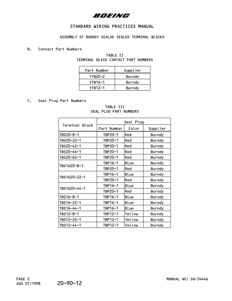
B. Contact Part Numbers
TABLE IITERMINAL BLOCK CONTACT PART NUMBERS
Part Number Supplier
YTB20-2 Burndy
YTB16-1 Burndy
YTB12-1 Burndy
C. Seal Plug Part Numbers
TABLE IIISEAL PLUG PART NUMBERS
Terminal BlockSeal Plug
Part Number Color Supplier
TBS20-8-1 TBP20-1 Red Burndy
TBS20-22-1 TBP20-1 Red Burndy
TBS20-42-1 TBP20-1 Red Burndy
TBS20-44-1 TBP20-1 Red Burndy
TBS20-62-1 TBP20-1 Red Burndy
TBS1620-8-1TBP16-1 Blue Burndy
TBP20-1 Red Burndy
TBS1620-22-1TBP16-1 Blue Burndy
TBP20-1 Red Burndy
TBS1620-44-1TBP16-1 Blue Burndy
TBP20-1 Red Burndy
TBS16-8-1 TBP16-1 Blue Burndy
TBS16-22-1 TBP16-1 Blue Burndy
TBS16-44-1 TBP16-1 Blue Burndy
TBS12-8-1 TBP12-1 Yellow Burndy
TBS12-22-1 TBP12-1 Yellow Burndy
TBS12-44-1 TBP12-1 Yellow Burndy
b
STANDARD WIRING PRACTICES MANUAL
ASSEMBLY OF BURNDY SEALOK SEALED TERMINAL BLOCKS
MANUAL NO: D6-54446PAGE 2AUG 01/1998 20-90-12
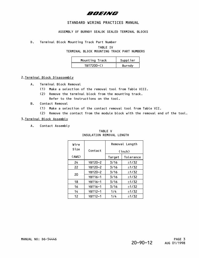
D. Terminal Block Mounting Track Part Number
TABLE IVTERMINAL BLOCK MOUNTING TRACK PART NUMBERS
Mounting Track Supplier
TBT7200-() Burndy
2.Terminal Block Disassembly
A. Terminal Block Removal
(1) Make a selection of the removal tool from Table VIII.
(2) Remove the terminal block from the mounting track.
Refer to the instructions on the tool.
B. Contact Removal
(1) Make a selection of the contact removal tool from Table VII.
(2) Remove the contact from the module block with the removal end of the tool.
3.Terminal Block Assembly
A. Contact Assembly
TABLE VINSULATION REMOVAL LENGTH
Wire
Size
(AWG)
Contact
Removal Length
(inch)
Target Tolerance
24 YBT20-2 3/16 ±1/3222 YBT20-2 3/16 ±1/32
20YBT20-2 3/16 ±1/32YBT16-1 3/16 ±1/32
18 YBT16-1 3/16 ±1/3216 YBT16-1 3/16 ±1/3214 YBT12-1 1/4 ±1/3212 YBT12-1 1/4 ±1/32
b
STANDARD WIRING PRACTICES MANUAL
ASSEMBLY OF BURNDY SEALOK SEALED TERMINAL BLOCKS
MANUAL NO: D6-54446 PAGE 3AUG 01/199820-90-12
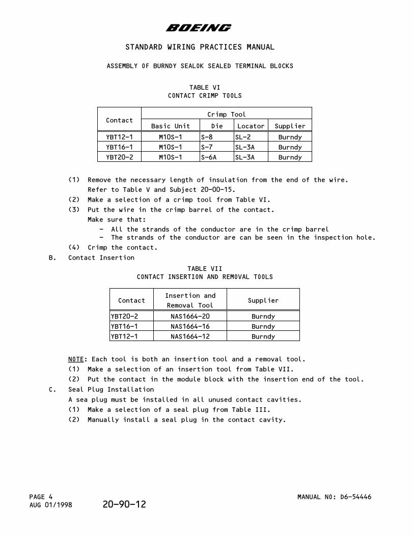
TABLE VICONTACT CRIMP TOOLS
ContactCrimp Tool
Basic Unit Die Locator Supplier
YBT12-1 M10S-1 S-8 SL-2 Burndy
YBT16-1 M10S-1 S-7 SL-3A Burndy
YBT20-2 M10S-1 S-6A SL-3A Burndy
(1) Remove the necessary length of insulation from the end of the wire.
Refer to Table V and Subject 20-00-15.
(2) Make a selection of a crimp tool from Table VI.
(3) Put the wire in the crimp barrel of the contact.
Make sure that:
- All the strands of the conductor are in the crimp barrel- The strands of the conductor are can be seen in the inspection hole.
(4) Crimp the contact.
B. Contact Insertion
TABLE VIICONTACT INSERTION AND REMOVAL TOOLS
ContactInsertion and
Removal ToolSupplier
YBT20-2 NAS1664-20 Burndy
YBT16-1 NAS1664-16 Burndy
YBT12-1 NAS1664-12 Burndy
NOTE: Each tool is both an insertion tool and a removal tool.
(1) Make a selection of an insertion tool from Table VII.
(2) Put the contact in the module block with the insertion end of the tool.
C. Seal Plug Installation
A sea plug must be installed in all unused contact cavities.
(1) Make a selection of a seal plug from Table III.
(2) Manually install a seal plug in the contact cavity.
b
STANDARD WIRING PRACTICES MANUAL
ASSEMBLY OF BURNDY SEALOK SEALED TERMINAL BLOCKS
MANUAL NO: D6-54446PAGE 4AUG 01/1998 20-90-12
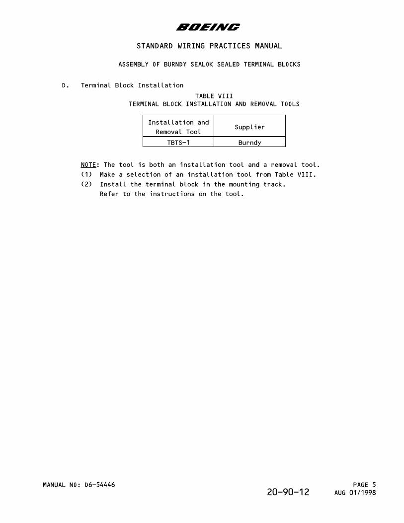
D. Terminal Block Installation
TABLE VIIITERMINAL BLOCK INSTALLATION AND REMOVAL TOOLS
Installation and
Removal ToolSupplier
TBTS-1 Burndy
NOTE: The tool is both an installation tool and a removal tool.
(1) Make a selection of an installation tool from Table VIII.
(2) Install the terminal block in the mounting track.
Refer to the instructions on the tool.
b
STANDARD WIRING PRACTICES MANUAL
ASSEMBLY OF BURNDY SEALOK SEALED TERMINAL BLOCKS
MANUAL NO: D6-54446 PAGE 5AUG 01/199820-90-12

This page is intentionally left blank
PARAGRAPH DESCRIPTION PAGE
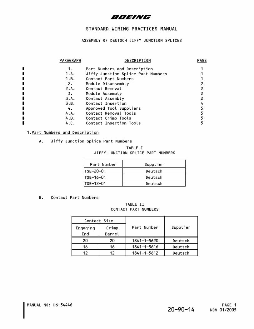
1. Part Numbers and Description 11.A. Jiffy Junction Splice Part Numbers 11.B. Contact Part Numbers 12. Module Disassembly 22.A. Contact Removal 23. Module Assembly 23.A. Contact Assembly 23.B. Contact Insertion 44. Approved Tool Suppliers 54.A. Contact Removal Tools 54.B. Contact Crimp Tools 54.C. Contact Insertion Tools 5
1.Part Numbers and Description
A. Jiffy Junction Splice Part Numbers
TABLE IJIFFY JUNCTION SPLICE PART NUMBERS
Part Number Supplier
TSE-20-01 Deutsch
TSE-16-01 Deutsch
TSE-12-01 Deutsch
B. Contact Part Numbers
TABLE IICONTACT PART NUMBERS
Contact Size
Part Number SupplierEngaging
End
Crimp
Barrel
20 20 1841-1-5620 Deutsch
16 16 1841-1-5616 Deutsch
12 12 1841-1-5612 Deutsch
b
STANDARD WIRING PRACTICES MANUAL
ASSEMBLY OF DEUTSCH JIFFY JUNCTION SPLICES
MANUAL NO: D6-54446 PAGE 1NOV 01/200520-90-14
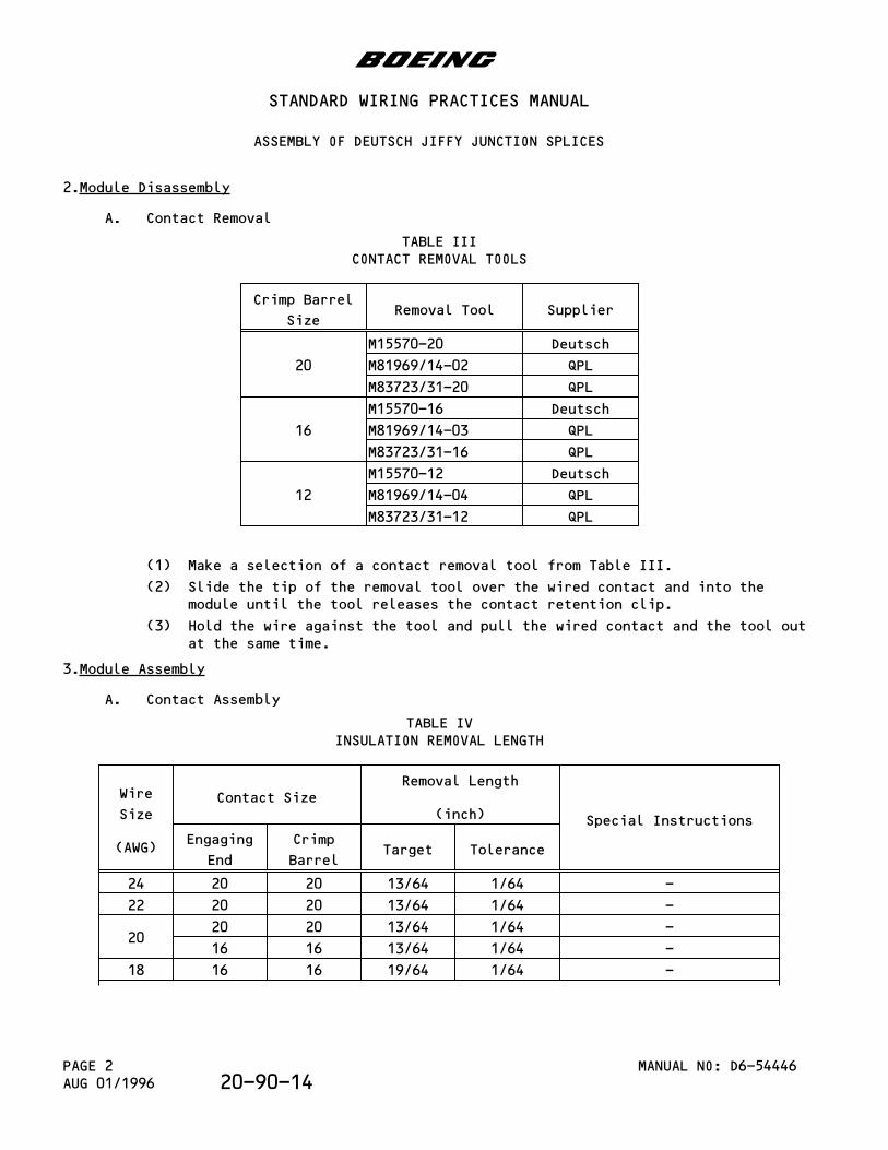
2.Module Disassembly
A. Contact Removal
TABLE IIICONTACT REMOVAL TOOLS
Crimp Barrel
SizeRemoval Tool Supplier
20
M15570-20 Deutsch
M81969/14-02 QPL
M83723/31-20 QPL
16
M15570-16 Deutsch
M81969/14-03 QPL
M83723/31-16 QPL
12
M15570-12 Deutsch
M81969/14-04 QPL
M83723/31-12 QPL
(1) Make a selection of a contact removal tool from Table III.
(2) Slide the tip of the removal tool over the wired contact and into themodule until the tool releases the contact retention clip.
(3) Hold the wire against the tool and pull the wired contact and the tool outat the same time.
3.Module Assembly
A. Contact Assembly
TABLE IVINSULATION REMOVAL LENGTH
Wire
Size
(AWG)
Contact SizeRemoval Length
(inch) Special Instructions
Engaging
End
Crimp
BarrelTarget Tolerance
24 20 20 13/64 1/64 -
22 20 20 13/64 1/64 -
2020 20 13/64 1/64 -
16 16 13/64 1/64 -
18 16 16 19/64 1/64 -
b
STANDARD WIRING PRACTICES MANUAL
ASSEMBLY OF DEUTSCH JIFFY JUNCTION SPLICES
MANUAL NO: D6-54446PAGE 2AUG 01/1996 20-90-14
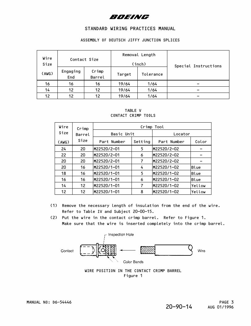
Wire
Size
(AWG)
Contact SizeRemoval Length
(inch) Special Instructions
Engaging
End
Crimp
BarrelTarget Tolerance
16 16 16 19/64 1/64 -
14 12 12 19/64 1/64 -
12 12 12 19/64 1/64 -
TABLE VCONTACT CRIMP TOOLS
Wire
Size
(AWG)
Crimp
Barrel
Size
Crimp Tool
Basic Unit Locator
Part Number Setting Part Number Color
24 20 M22520/2-01 5 M22520/2-02 -
22 20 M22520/2-01 6 M22520/2-02 -
20 20 M22520/2-01 7 M22520/2-02 -
20 16 M22520/1-01 4 M22520/1-02 Blue
18 16 M22520/1-01 5 M22520/1-02 Blue
16 16 M22520/1-01 6 M22520/1-02 Blue
14 12 M22520/1-01 7 M22520/1-02 Yellow
12 12 M22520/1-01 8 M22520/1-02 Yellow
(1) Remove the necessary length of insulation from the end of the wire.
Refer to Table IV and Subject 20-00-15.
(2) Put the wire in the contact crimp barrel. Refer to Figure 1.
Make sure that the wire is inserted completely into the crimp barrel.
WIRE POSITION IN THE CONTACT CRIMP BARRELFigure 1
b
STANDARD WIRING PRACTICES MANUAL
ASSEMBLY OF DEUTSCH JIFFY JUNCTION SPLICES
MANUAL NO: D6-54446 PAGE 3AUG 01/199620-90-14
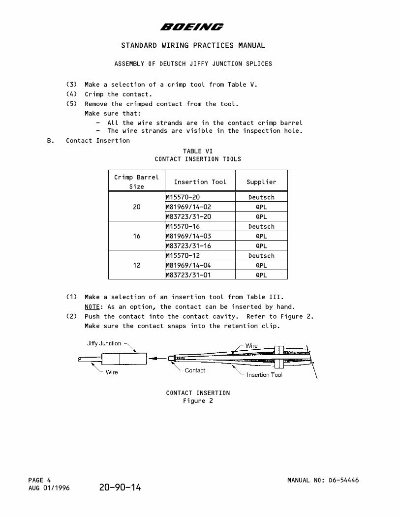
(3) Make a selection of a crimp tool from Table V.
(4) Crimp the contact.
(5) Remove the crimped contact from the tool.
Make sure that:
- All the wire strands are in the contact crimp barrel- The wire strands are visible in the inspection hole.
B. Contact Insertion
TABLE VICONTACT INSERTION TOOLS
Crimp Barrel
SizeInsertion Tool Supplier
20
M15570-20 Deutsch
M81969/14-02 QPL
M83723/31-20 QPL
16
M15570-16 Deutsch
M81969/14-03 QPL
M83723/31-16 QPL
12
M15570-12 Deutsch
M81969/14-04 QPL
M83723/31-01 QPL
(1) Make a selection of an insertion tool from Table III.
NOTE: As an option, the contact can be inserted by hand.
(2) Push the contact into the contact cavity. Refer to Figure 2.
Make sure the contact snaps into the retention clip.
CONTACT INSERTIONFigure 2
b
STANDARD WIRING PRACTICES MANUAL
ASSEMBLY OF DEUTSCH JIFFY JUNCTION SPLICES
MANUAL NO: D6-54446PAGE 4AUG 01/1996 20-90-14
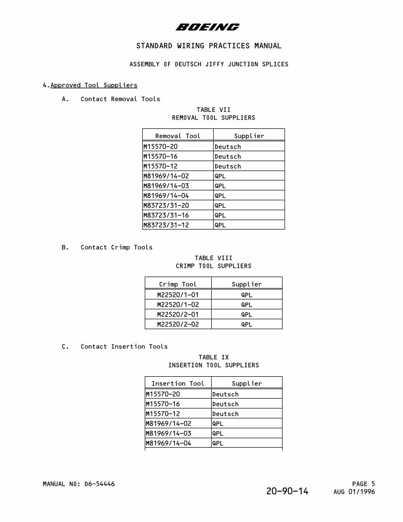
4.Approved Tool Suppliers
A. Contact Removal Tools
TABLE VIIREMOVAL TOOL SUPPLIERS
Removal Tool Supplier
M15570-20 Deutsch
M15570-16 Deutsch
M15570-12 Deutsch
M81969/14-02 QPL
M81969/14-03 QPL
M81969/14-04 QPL
M83723/31-20 QPL
M83723/31-16 QPL
M83723/31-12 QPL
B. Contact Crimp Tools
TABLE VIIICRIMP TOOL SUPPLIERS
Crimp Tool Supplier
M22520/1-01 QPL
M22520/1-02 QPL
M22520/2-01 QPL
M22520/2-02 QPL
C. Contact Insertion Tools
TABLE IXINSERTION TOOL SUPPLIERS
Insertion Tool Supplier
M15570-20 Deutsch
M15570-16 Deutsch
M15570-12 Deutsch
M81969/14-02 QPL
M81969/14-03 QPL
M81969/14-04 QPL
b
STANDARD WIRING PRACTICES MANUAL
ASSEMBLY OF DEUTSCH JIFFY JUNCTION SPLICES
MANUAL NO: D6-54446 PAGE 5AUG 01/199620-90-14
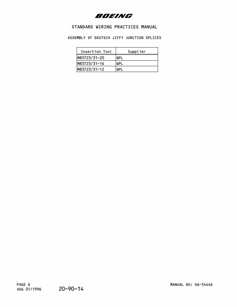
Insertion Tool Supplier
M83723/31-20 QPL
M83723/31-16 QPL
M83723/31-12 QPL
b
STANDARD WIRING PRACTICES MANUAL
ASSEMBLY OF DEUTSCH JIFFY JUNCTION SPLICES
MANUAL NO: D6-54446PAGE 6AUG 01/1996 20-90-14
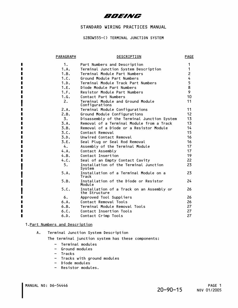
PARAGRAPH DESCRIPTION PAGE
1. Part Numbers and Description 11.A. Terminal Junction System Description 11.B. Terminal Module Part Numbers 21.C. Ground Module Part Numbers 41.D. Terminal Module Track Part Numbers 51.E. Diode Module Part Numbers 81.F. Resistor Module Part Numbers 91.G. Contact Part Numbers 102. Terminal Module and Ground Module
Configurations11
2.A. Terminal Module Configurations 112.B. Ground Module Configurations 123. Disassembly of the Terminal Junction System 133.A. Removal of a Terminal Module from a Track 133.B. Removal of a Diode or a Resistor Module 143.C. Contact Removal 153.D. Unwired Contact Removal 163.E. Seal Plug or Seal Rod Removal 164. Assembly of the Terminal Module 174.A. Contact Assembly 174.B. Contact Insertion 194.C. Seal of an Empty Contact Cavity 225. Installation of the Terminal Junction
System23
5.A. Installation of a Terminal Module on aTrack
23
5.B. Installation of the Diode or ResistorModule
24
5.C. Installation of a Track on an Assembly orthe Structure
26
6. Approved Tool Suppliers 266.A. Contact Removal Tools 266.B. Terminal Module Removal Tools 276.C. Contact Insertion Tools 276.D. Contact Crimp Tools 27
1.Part Numbers and Description
A. Terminal Junction System Description
The terminal junction system has these components:
- Terminal modules- Ground modules- Tracks- Tracks with ground modules- Diode modules- Resistor modules.
b
STANDARD WIRING PRACTICES MANUAL
S280W555-() TERMINAL JUNCTION SYSTEM
MANUAL NO: D6-54446 PAGE 1NOV 01/200520-90-15
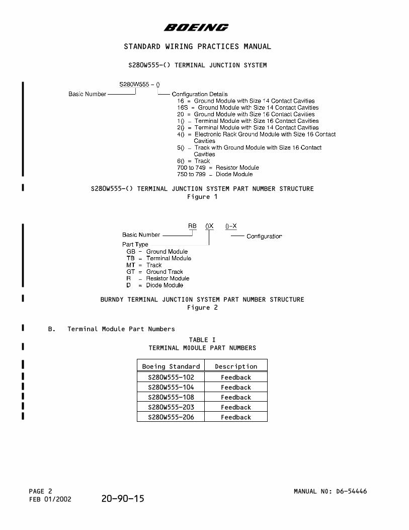
S280W555-() TERMINAL JUNCTION SYSTEM PART NUMBER STRUCTUREFigure 1
BURNDY TERMINAL JUNCTION SYSTEM PART NUMBER STRUCTUREFigure 2
B. Terminal Module Part Numbers
TABLE ITERMINAL MODULE PART NUMBERS
Boeing Standard Description
S280W555-102 Feedback
S280W555-104 Feedback
S280W555-108 Feedback
S280W555-203 Feedback
S280W555-206 Feedback
b
STANDARD WIRING PRACTICES MANUAL
S280W555-() TERMINAL JUNCTION SYSTEM
MANUAL NO: D6-54446PAGE 2FEB 01/2002 20-90-15
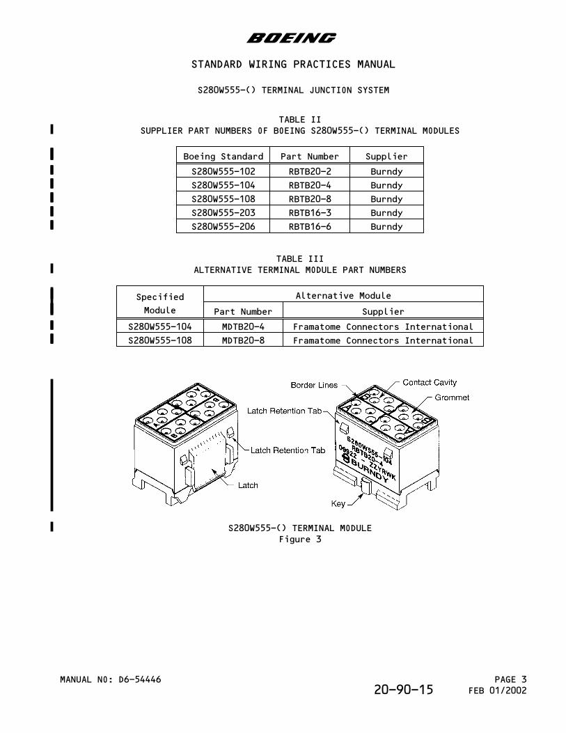
TABLE IISUPPLIER PART NUMBERS OF BOEING S280W555-() TERMINAL MODULES
Boeing Standard Part Number Supplier
S280W555-102 RBTB20-2 Burndy
S280W555-104 RBTB20-4 Burndy
S280W555-108 RBTB20-8 Burndy
S280W555-203 RBTB16-3 Burndy
S280W555-206 RBTB16-6 Burndy
TABLE IIIALTERNATIVE TERMINAL MODULE PART NUMBERS
Specified
Module
Alternative Module
Part Number Supplier
S280W555-104 MDTB20-4 Framatome Connectors International
S280W555-108 MDTB20-8 Framatome Connectors International
S280W555-() TERMINAL MODULEFigure 3
b
STANDARD WIRING PRACTICES MANUAL
S280W555-() TERMINAL JUNCTION SYSTEM
MANUAL NO: D6-54446 PAGE 3FEB 01/200220-90-15
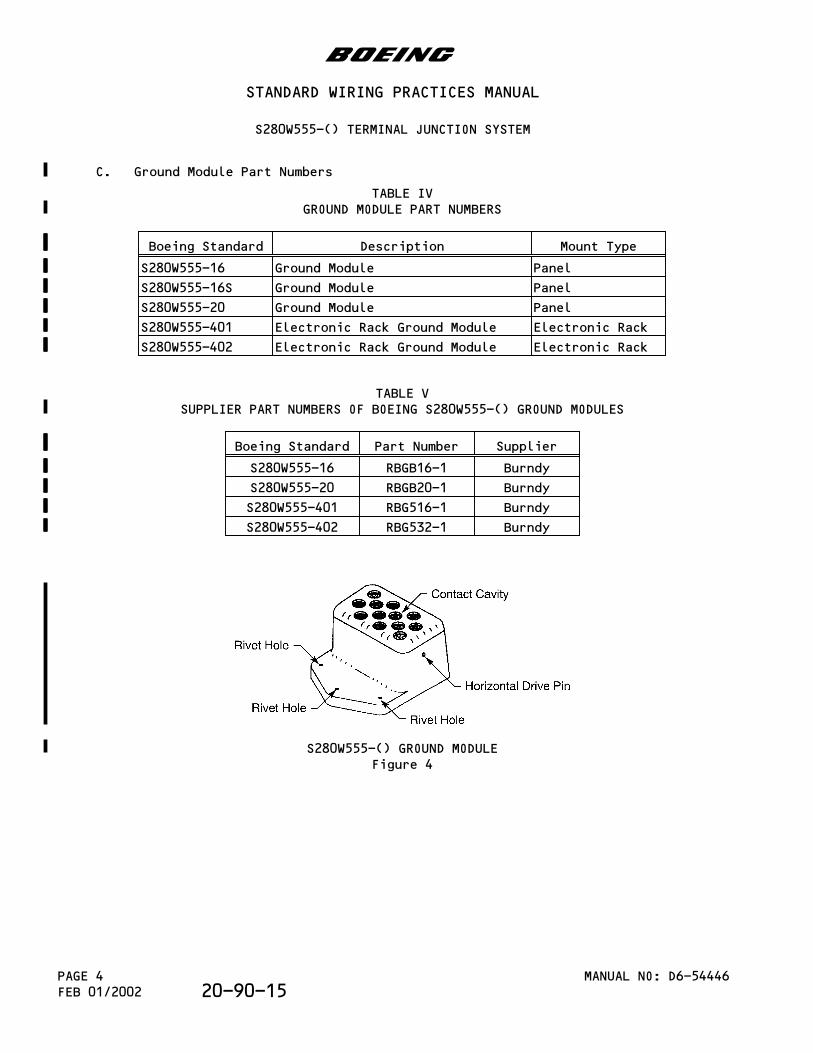
C. Ground Module Part Numbers
TABLE IVGROUND MODULE PART NUMBERS
Boeing Standard Description Mount Type
S280W555-16 Ground Module Panel
S280W555-16S Ground Module Panel
S280W555-20 Ground Module Panel
S280W555-401 Electronic Rack Ground Module Electronic Rack
S280W555-402 Electronic Rack Ground Module Electronic Rack
TABLE VSUPPLIER PART NUMBERS OF BOEING S280W555-() GROUND MODULES
Boeing Standard Part Number Supplier
S280W555-16 RBGB16-1 Burndy
S280W555-20 RBGB20-1 Burndy
S280W555-401 RBG516-1 Burndy
S280W555-402 RBG532-1 Burndy
S280W555-() GROUND MODULEFigure 4
b
STANDARD WIRING PRACTICES MANUAL
S280W555-() TERMINAL JUNCTION SYSTEM
MANUAL NO: D6-54446PAGE 4FEB 01/2002 20-90-15
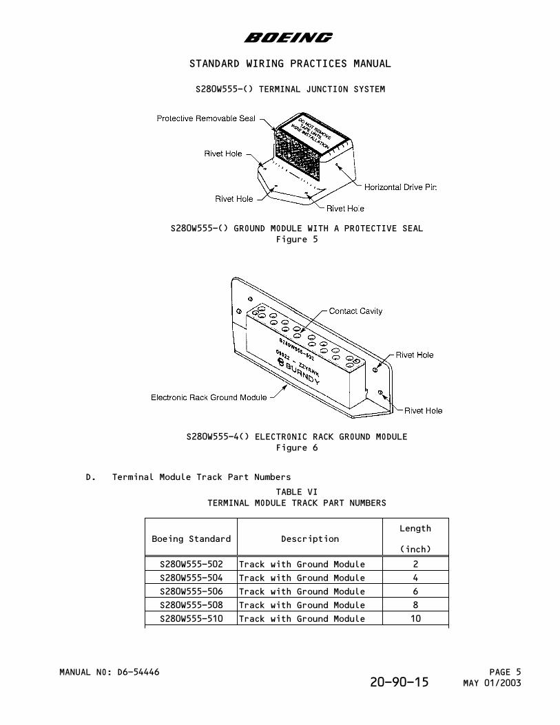
S280W555-() GROUND MODULE WITH A PROTECTIVE SEALFigure 5
S280W555-4() ELECTRONIC RACK GROUND MODULEFigure 6
D. Terminal Module Track Part Numbers
TABLE VITERMINAL MODULE TRACK PART NUMBERS
Boeing Standard DescriptionLength
(inch)
S280W555-502 Track with Ground Module 2
S280W555-504 Track with Ground Module 4
S280W555-506 Track with Ground Module 6
S280W555-508 Track with Ground Module 8
S280W555-510 Track with Ground Module 10
b
STANDARD WIRING PRACTICES MANUAL
S280W555-() TERMINAL JUNCTION SYSTEM
MANUAL NO: D6-54446 PAGE 5MAY 01/200320-90-15
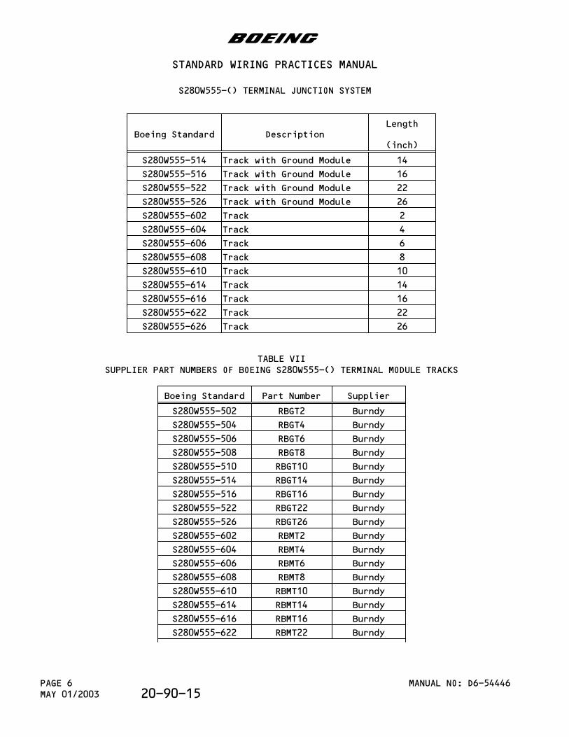
Boeing Standard DescriptionLength
(inch)
S280W555-514 Track with Ground Module 14
S280W555-516 Track with Ground Module 16
S280W555-522 Track with Ground Module 22
S280W555-526 Track with Ground Module 26
S280W555-602 Track 2
S280W555-604 Track 4
S280W555-606 Track 6
S280W555-608 Track 8
S280W555-610 Track 10
S280W555-614 Track 14
S280W555-616 Track 16
S280W555-622 Track 22
S280W555-626 Track 26
TABLE VIISUPPLIER PART NUMBERS OF BOEING S280W555-() TERMINAL MODULE TRACKS
Boeing Standard Part Number Supplier
S280W555-502 RBGT2 Burndy
S280W555-504 RBGT4 Burndy
S280W555-506 RBGT6 Burndy
S280W555-508 RBGT8 Burndy
S280W555-510 RBGT10 Burndy
S280W555-514 RBGT14 Burndy
S280W555-516 RBGT16 Burndy
S280W555-522 RBGT22 Burndy
S280W555-526 RBGT26 Burndy
S280W555-602 RBMT2 Burndy
S280W555-604 RBMT4 Burndy
S280W555-606 RBMT6 Burndy
S280W555-608 RBMT8 Burndy
S280W555-610 RBMT10 Burndy
S280W555-614 RBMT14 Burndy
S280W555-616 RBMT16 Burndy
S280W555-622 RBMT22 Burndy
b
STANDARD WIRING PRACTICES MANUAL
S280W555-() TERMINAL JUNCTION SYSTEM
MANUAL NO: D6-54446PAGE 6MAY 01/2003 20-90-15
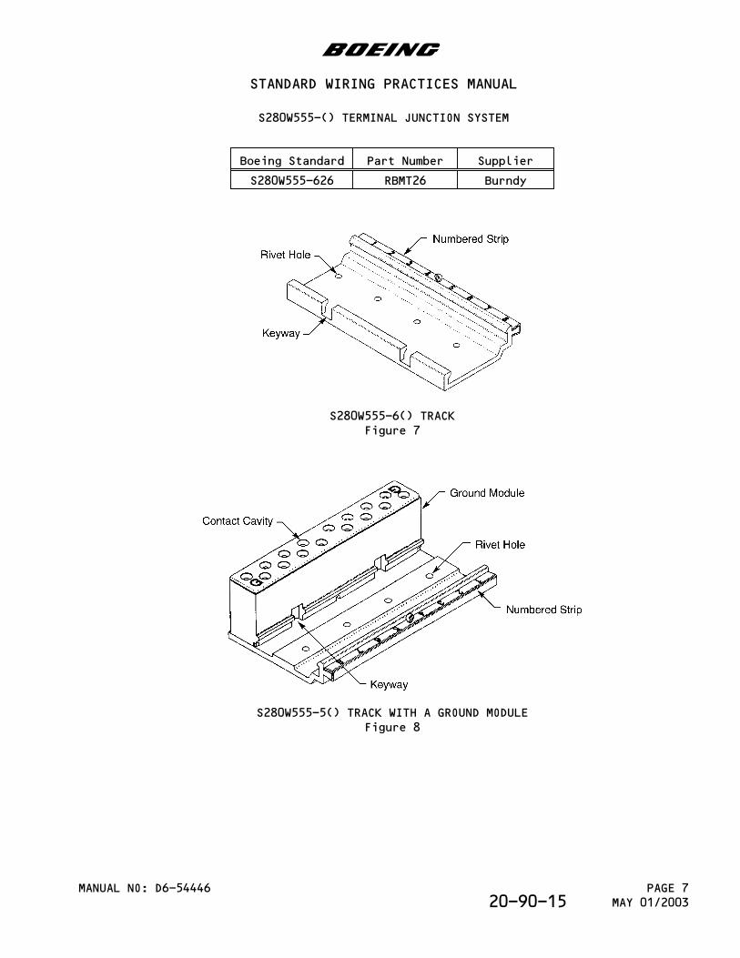
Boeing Standard Part Number Supplier
S280W555-626 RBMT26 Burndy
S280W555-6() TRACKFigure 7
S280W555-5() TRACK WITH A GROUND MODULEFigure 8
b
STANDARD WIRING PRACTICES MANUAL
S280W555-() TERMINAL JUNCTION SYSTEM
MANUAL NO: D6-54446 PAGE 7MAY 01/200320-90-15
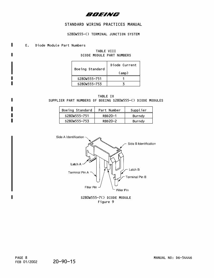
E. Diode Module Part Numbers
TABLE VIIIDIODE MODULE PART NUMBERS
Boeing StandardDiode Current
(amp)
S280W555-751 1
S280W555-753 3
TABLE IXSUPPLIER PART NUMBERS OF BOEING S280W555-() DIODE MODULES
Boeing Standard Part Number Supplier
S280W555-751 RBD20-1 Burndy
S280W555-753 RBD20-2 Burndy
S280W555-7() DIODE MODULEFigure 9
b
STANDARD WIRING PRACTICES MANUAL
S280W555-() TERMINAL JUNCTION SYSTEM
MANUAL NO: D6-54446PAGE 8FEB 01/2002 20-90-15
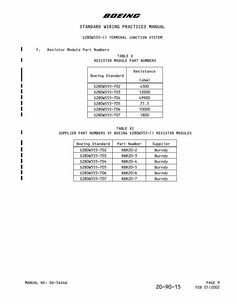
F. Resistor Module Part Numbers
TABLE XRESISTOR MODULE PART NUMBERS
Boeing StandardResistance
(ohm)
S280W555-702 4300
S280W555-703 12000
S280W555-704 49900
S280W555-705 71.5
S280W555-706 10000
S280W555-707 1800
TABLE XISUPPLIER PART NUMBERS OF BOEING S280W555-() RESISTOR MODULES
Boeing Standard Part Number Supplier
S280W555-702 RBR20-2 Burndy
S280W555-703 RBR20-3 Burndy
S280W555-704 RBR20-4 Burndy
S280W555-705 RBR20-5 Burndy
S280W555-706 RBR20-6 Burndy
S280W555-707 RBR20-7 Burndy
b
STANDARD WIRING PRACTICES MANUAL
S280W555-() TERMINAL JUNCTION SYSTEM
MANUAL NO: D6-54446 PAGE 9FEB 01/200220-90-15
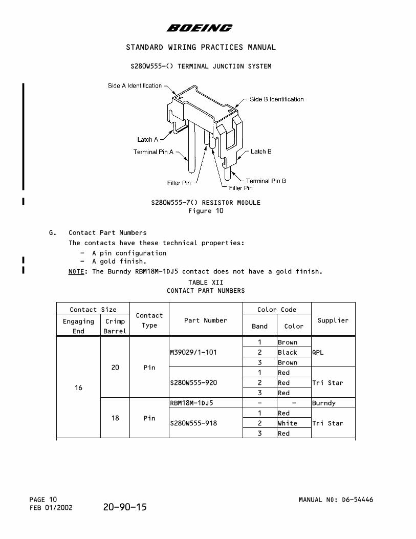
S280W555-7() RESISTOR MODULEFigure 10
G. Contact Part Numbers
The contacts have these technical properties:
- A pin configuration- A gold finish.
NOTE: The Burndy RBM18M-1DJ5 contact does not have a gold finish.
TABLE XIICONTACT PART NUMBERS
Contact SizeContact
TypePart Number
Color Code
SupplierEngaging
End
Crimp
BarrelBand Color
16
20 Pin
M39029/1-101
1 Brown
QPL2 Black
3 Brown
S280W555-920
1 Red
Tri Star2 Red
3 Red
18 Pin
RBM18M-1DJ5 - - Burndy
S280W555-918
1 Red
Tri Star2 White
3 Red
b
STANDARD WIRING PRACTICES MANUAL
S280W555-() TERMINAL JUNCTION SYSTEM
MANUAL NO: D6-54446PAGE 10FEB 01/2002 20-90-15
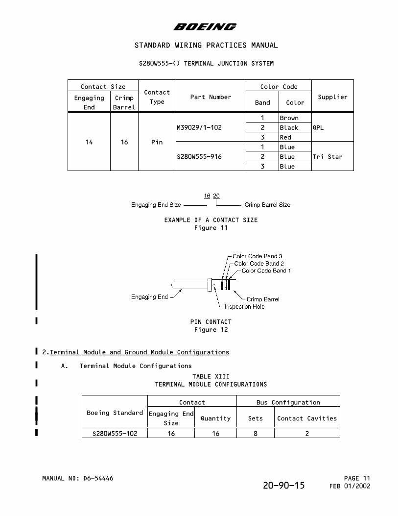
Contact SizeContact
TypePart Number
Color Code
SupplierEngaging
End
Crimp
BarrelBand Color
14 16 Pin
M39029/1-102
1 Brown
QPL2 Black
3 Red
S280W555-916
1 Blue
Tri Star2 Blue
3 Blue
EXAMPLE OF A CONTACT SIZEFigure 11
PIN CONTACTFigure 12
2.Terminal Module and Ground Module Configurations
A. Terminal Module Configurations
TABLE XIIITERMINAL MODULE CONFIGURATIONS
Boeing Standard
Contact Bus Configuration
Engaging End
SizeQuantity Sets Contact Cavities
S280W555-102 16 16 8 2
b
STANDARD WIRING PRACTICES MANUAL
S280W555-() TERMINAL JUNCTION SYSTEM
MANUAL NO: D6-54446 PAGE 11FEB 01/200220-90-15
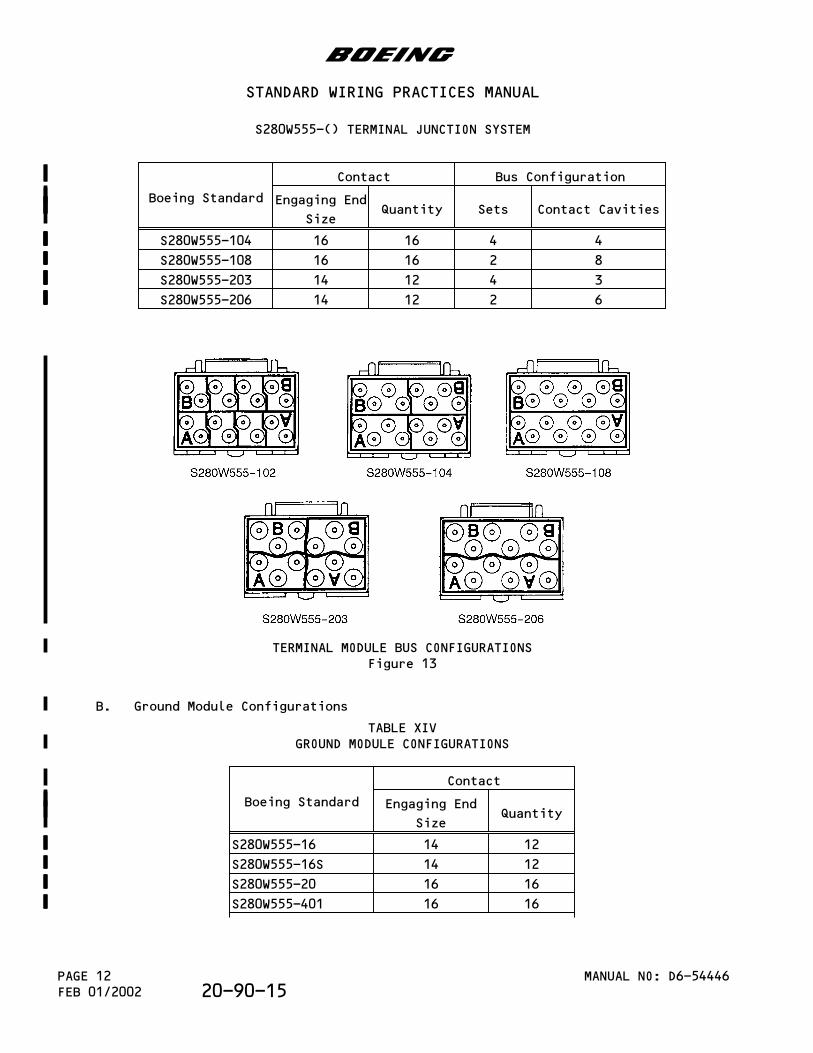
Boeing Standard
Contact Bus Configuration
Engaging End
SizeQuantity Sets Contact Cavities
S280W555-104 16 16 4 4
S280W555-108 16 16 2 8
S280W555-203 14 12 4 3
S280W555-206 14 12 2 6
TERMINAL MODULE BUS CONFIGURATIONSFigure 13
B. Ground Module Configurations
TABLE XIVGROUND MODULE CONFIGURATIONS
Boeing Standard
Contact
Engaging End
SizeQuantity
S280W555-16 14 12
S280W555-16S 14 12
S280W555-20 16 16
S280W555-401 16 16
b
STANDARD WIRING PRACTICES MANUAL
S280W555-() TERMINAL JUNCTION SYSTEM
MANUAL NO: D6-54446PAGE 12FEB 01/2002 20-90-15
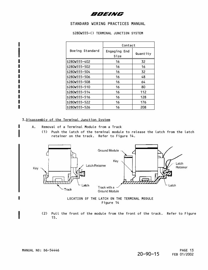
Boeing Standard
Contact
Engaging End
SizeQuantity
S280W555-402 16 32
S280W555-502 16 16
S280W555-504 16 32
S280W555-506 16 48
S280W555-508 16 64
S280W555-510 16 80
S280W555-514 16 112
S280W555-516 16 128
S280W555-522 16 176
S280W555-526 16 208
3.Disassembly of the Terminal Junction System
A. Removal of a Terminal Module from a Track
(1) Push the latch of the terminal module to release the latch from the latchretainer on the track. Refer to Figure 14.
LOCATION OF THE LATCH ON THE TERMINAL MODULEFigure 14
(2) Pull the front of the module from the front of the track. Refer to Figure15.
b
STANDARD WIRING PRACTICES MANUAL
S280W555-() TERMINAL JUNCTION SYSTEM
MANUAL NO: D6-54446 PAGE 13FEB 01/200220-90-15
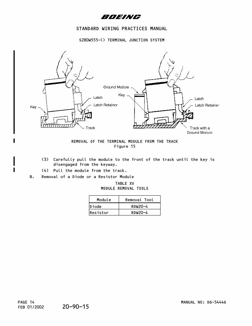
REMOVAL OF THE TERMINAL MODULE FROM THE TRACKFigure 15
(3) Carefully pull the module to the front of the track until the key isdisengaged from the keyway.
(4) Pull the module from the track.
B. Removal of a Diode or a Resistor Module
TABLE XVMODULE REMOVAL TOOLS
Module Removal Tool
Diode RDW20-4
Resistor RDW20-4
b
STANDARD WIRING PRACTICES MANUAL
S280W555-() TERMINAL JUNCTION SYSTEM
MANUAL NO: D6-54446PAGE 14FEB 01/2002 20-90-15
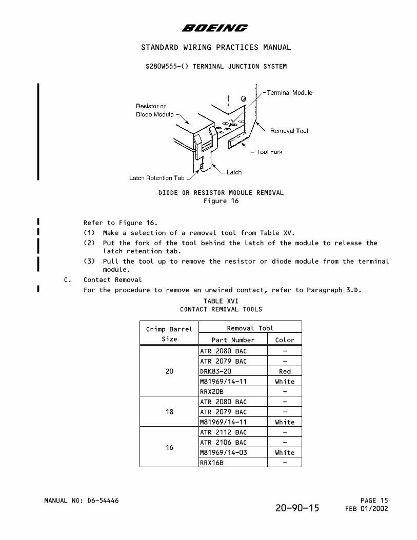
DIODE OR RESISTOR MODULE REMOVALFigure 16
Refer to Figure 16.
(1) Make a selection of a removal tool from Table XV.
(2) Put the fork of the tool behind the latch of the module to release thelatch retention tab.
(3) Pull the tool up to remove the resistor or diode module from the terminalmodule.
C. Contact Removal
For the procedure to remove an unwired contact, refer to Paragraph 3.D.
TABLE XVICONTACT REMOVAL TOOLS
Crimp Barrel
Size
Removal Tool
Part Number Color
20
ATR 2080 BAC -
ATR 2079 BAC -
DRK83-20 Red
M81969/14-11 White
RRX20B -
18
ATR 2080 BAC -
ATR 2079 BAC -
M81969/14-11 White
16
ATR 2112 BAC -
ATR 2106 BAC -
M81969/14-03 White
RRX16B -
b
STANDARD WIRING PRACTICES MANUAL
S280W555-() TERMINAL JUNCTION SYSTEM
MANUAL NO: D6-54446 PAGE 15FEB 01/200220-90-15
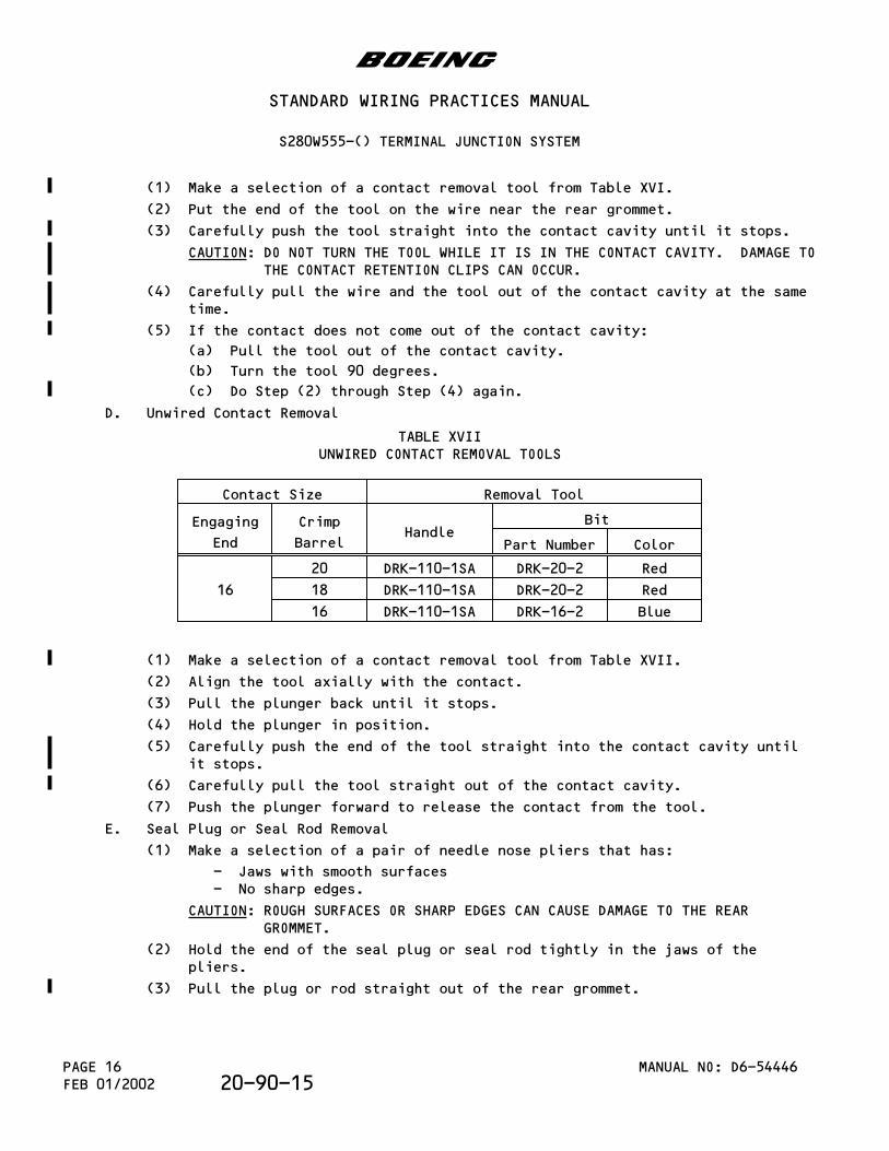
(1) Make a selection of a contact removal tool from Table XVI.
(2) Put the end of the tool on the wire near the rear grommet.
(3) Carefully push the tool straight into the contact cavity until it stops.
CAUTION: DO NOT TURN THE TOOL WHILE IT IS IN THE CONTACT CAVITY. DAMAGE TOTHE CONTACT RETENTION CLIPS CAN OCCUR.
(4) Carefully pull the wire and the tool out of the contact cavity at the sametime.
(5) If the contact does not come out of the contact cavity:
(a) Pull the tool out of the contact cavity.
(b) Turn the tool 90 degrees.
(c) Do Step (2) through Step (4) again.
D. Unwired Contact Removal
TABLE XVIIUNWIRED CONTACT REMOVAL TOOLS
Contact Size Removal Tool
Engaging
End
Crimp
BarrelHandle
Bit
Part Number Color
16
20 DRK-110-1SA DRK-20-2 Red
18 DRK-110-1SA DRK-20-2 Red
16 DRK-110-1SA DRK-16-2 Blue
(1) Make a selection of a contact removal tool from Table XVII.
(2) Align the tool axially with the contact.
(3) Pull the plunger back until it stops.
(4) Hold the plunger in position.
(5) Carefully push the end of the tool straight into the contact cavity untilit stops.
(6) Carefully pull the tool straight out of the contact cavity.
(7) Push the plunger forward to release the contact from the tool.
E. Seal Plug or Seal Rod Removal
(1) Make a selection of a pair of needle nose pliers that has:
- Jaws with smooth surfaces- No sharp edges.
CAUTION: ROUGH SURFACES OR SHARP EDGES CAN CAUSE DAMAGE TO THE REARGROMMET.
(2) Hold the end of the seal plug or seal rod tightly in the jaws of thepliers.
(3) Pull the plug or rod straight out of the rear grommet.
b
STANDARD WIRING PRACTICES MANUAL
S280W555-() TERMINAL JUNCTION SYSTEM
MANUAL NO: D6-54446PAGE 16FEB 01/2002 20-90-15

4.Assembly of the Terminal Module
A. Contact Assembly
TABLE XVIIIINSULATION REMOVAL LENGTH
Wire
Size
(AWG)
Crimp
Barrel
Size
Removal Length L
(inch) Special Instructions
Target Tolerance
2420 0.15 ±0.02 -
16 0.54 ±0.04 Fold the conductor back
2220 0.15 ±0.02 -
16 0.54 ±0.04 Fold the conductor back
2020 0.15 ±0.02 -
16 0.27 ±0.02 -
1818 0.15 ±0.02 -
16 0.27 ±0.02 -
16 16 0.27 ±0.02 -
TABLE XIXCONTACT CRIMP TOOLS
Wire
Size
(AWG)
Crimp
Barrel
Size
Crimp Tool
Basic Unit Locator
Part Number Setting Part Number Color
24
20
M22520/1-01 2 M22520/1-02 Red
M22520/2-01 5 M22520/2-11 -
WA22 5 M22520/2-11 -
WA22LC 5 M22520/2-11 -
WA27 2 M22520/1-02 Red
16
M22520/1-01 5 M22520/1-02 Blue
ST2220-1-Y - ST2220-1-2 -
WA27F 5 M22520/1-02 Blue
b
STANDARD WIRING PRACTICES MANUAL
S280W555-() TERMINAL JUNCTION SYSTEM
MANUAL NO: D6-54446 PAGE 17FEB 01/200220-90-15
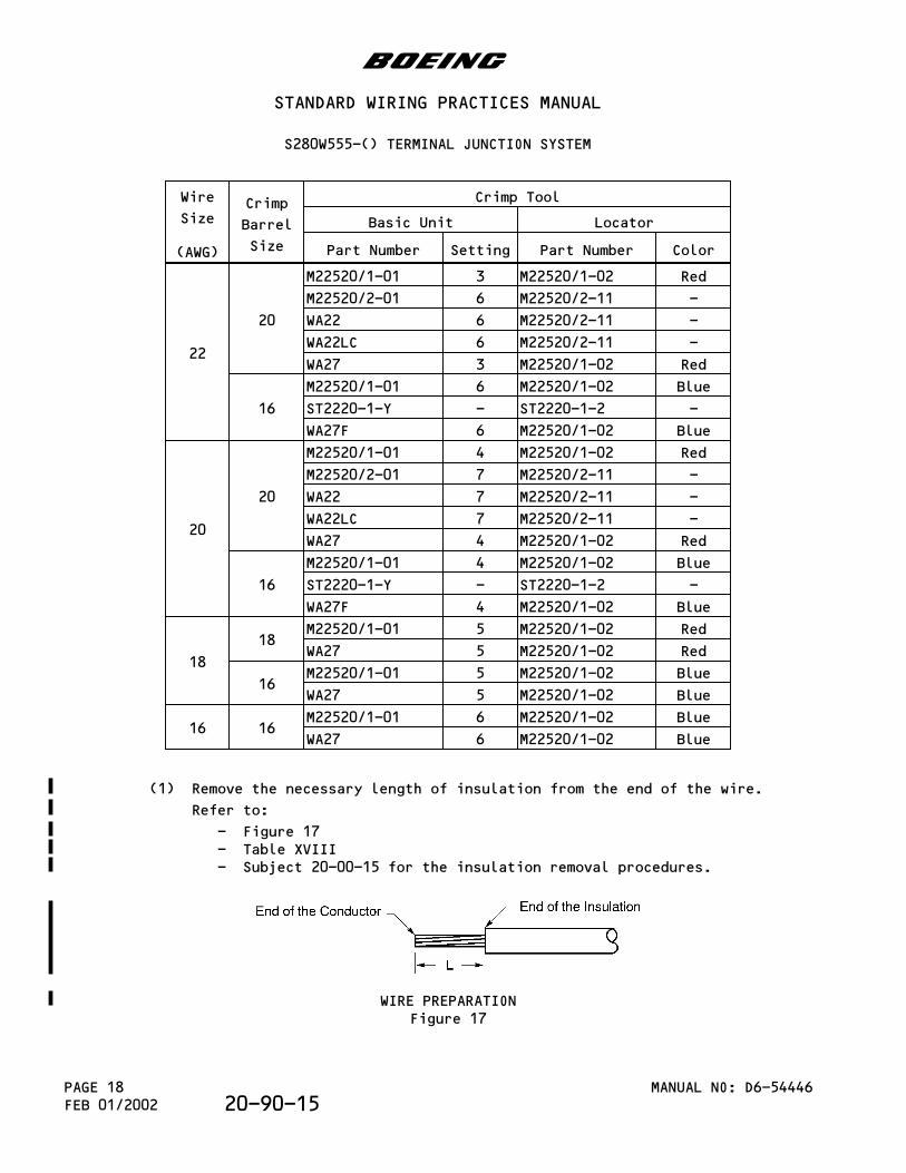
Wire
Size
(AWG)
Crimp
Barrel
Size
Crimp Tool
Basic Unit Locator
Part Number Setting Part Number Color
22
20
M22520/1-01 3 M22520/1-02 Red
M22520/2-01 6 M22520/2-11 -
WA22 6 M22520/2-11 -
WA22LC 6 M22520/2-11 -
WA27 3 M22520/1-02 Red
16
M22520/1-01 6 M22520/1-02 Blue
ST2220-1-Y - ST2220-1-2 -
WA27F 6 M22520/1-02 Blue
20
20
M22520/1-01 4 M22520/1-02 Red
M22520/2-01 7 M22520/2-11 -
WA22 7 M22520/2-11 -
WA22LC 7 M22520/2-11 -
WA27 4 M22520/1-02 Red
16
M22520/1-01 4 M22520/1-02 Blue
ST2220-1-Y - ST2220-1-2 -
WA27F 4 M22520/1-02 Blue
18
18M22520/1-01 5 M22520/1-02 Red
WA27 5 M22520/1-02 Red
16M22520/1-01 5 M22520/1-02 Blue
WA27 5 M22520/1-02 Blue
16 16M22520/1-01 6 M22520/1-02 Blue
WA27 6 M22520/1-02 Blue
(1) Remove the necessary length of insulation from the end of the wire.
Refer to:
- Figure 17- Table XVIII- Subject 20-00-15 for the insulation removal procedures.
WIRE PREPARATIONFigure 17
b
STANDARD WIRING PRACTICES MANUAL
S280W555-() TERMINAL JUNCTION SYSTEM
MANUAL NO: D6-54446PAGE 18FEB 01/2002 20-90-15
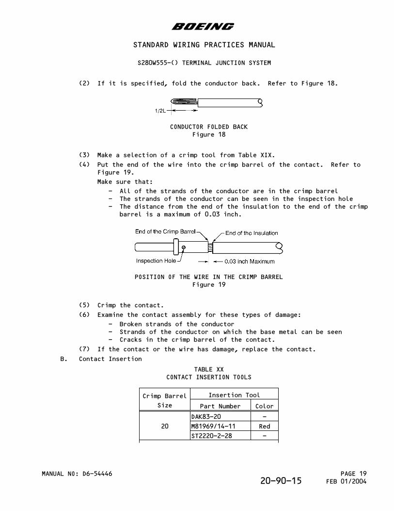
(2) If it is specified, fold the conductor back. Refer to Figure 18.
CONDUCTOR FOLDED BACKFigure 18
(3) Make a selection of a crimp tool from Table XIX.
(4) Put the end of the wire into the crimp barrel of the contact. Refer toFigure 19.
Make sure that:
- All of the strands of the conductor are in the crimp barrel- The strands of the conductor can be seen in the inspection hole- The distance from the end of the insulation to the end of the crimp
barrel is a maximum of 0.03 inch.
POSITION OF THE WIRE IN THE CRIMP BARRELFigure 19
(5) Crimp the contact.
(6) Examine the contact assembly for these types of damage:
- Broken strands of the conductor- Strands of the conductor on which the base metal can be seen- Cracks in the crimp barrel of the contact.
(7) If the contact or the wire has damage, replace the contact.
B. Contact Insertion
TABLE XXCONTACT INSERTION TOOLS
Crimp Barrel
Size
Insertion Tool
Part Number Color
20
DAK83-20 -
M81969/14-11 Red
ST2220-2-28 -
b
STANDARD WIRING PRACTICES MANUAL
S280W555-() TERMINAL JUNCTION SYSTEM
MANUAL NO: D6-54446 PAGE 19FEB 01/200420-90-15
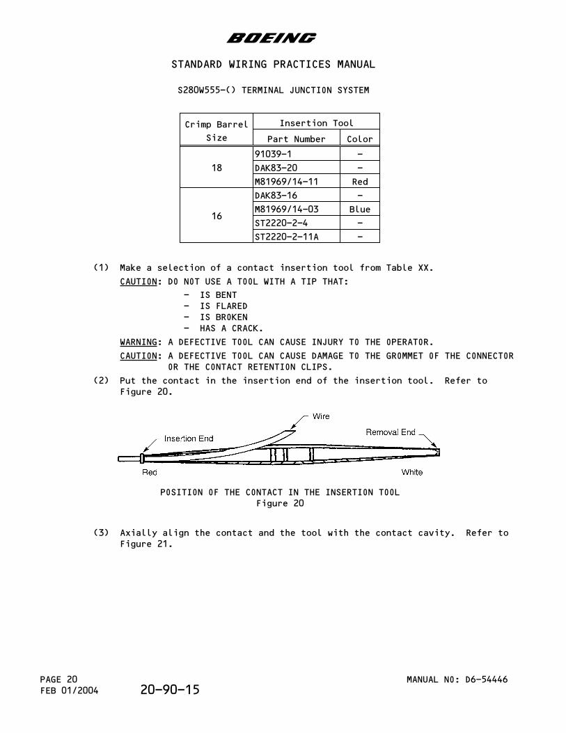
Crimp Barrel
Size
Insertion Tool
Part Number Color
18
91039-1 -
DAK83-20 -
M81969/14-11 Red
16
DAK83-16 -
M81969/14-03 Blue
ST2220-2-4 -
ST2220-2-11A -
(1) Make a selection of a contact insertion tool from Table XX.
CAUTION: DO NOT USE A TOOL WITH A TIP THAT:
- IS BENT- IS FLARED- IS BROKEN- HAS A CRACK.
WARNING: A DEFECTIVE TOOL CAN CAUSE INJURY TO THE OPERATOR.
CAUTION: A DEFECTIVE TOOL CAN CAUSE DAMAGE TO THE GROMMET OF THE CONNECTOROR THE CONTACT RETENTION CLIPS.
(2) Put the contact in the insertion end of the insertion tool. Refer toFigure 20.
POSITION OF THE CONTACT IN THE INSERTION TOOLFigure 20
(3) Axially align the contact and the tool with the contact cavity. Refer toFigure 21.
b
STANDARD WIRING PRACTICES MANUAL
S280W555-() TERMINAL JUNCTION SYSTEM
MANUAL NO: D6-54446PAGE 20FEB 01/2004 20-90-15
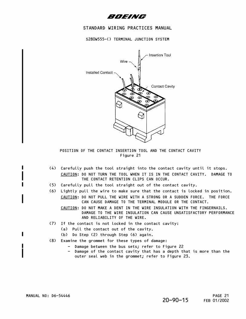
POSITION OF THE CONTACT INSERTION TOOL AND THE CONTACT CAVITYFigure 21
(4) Carefully push the tool straight into the contact cavity until it stops.
CAUTION: DO NOT TURN THE TOOL WHEN IT IS IN THE CONTACT CAVITY. DAMAGE TOTHE CONTACT RETENTION CLIPS CAN OCCUR.
(5) Carefully pull the tool straight out of the contact cavity.
(6) Lightly pull the wire to make sure that the contact is locked in position.
CAUTION: DO NOT PULL THE WIRE WITH A STRONG OR A SUDDEN FORCE. THE FORCECAN CAUSE DAMAGE TO THE TERMINAL MODULE OR THE CONTACT.
CAUTION: DO NOT MAKE A DENT IN THE WIRE INSULATION WITH THE FINGERNAILS.DAMAGE TO THE WIRE INSULATION CAN CAUSE UNSATISFACTORY PERFORMANCEAND RELIABILITY OF THE WIRE.
(7) If the contact is not locked in the contact cavity:
(a) Pull the contact out of the cavity.
(b) Do Step (2) through Step (6) again.
(8) Examine the grommet for these types of damage:
- Damage between the bus sets; refer to Figure 22- Damage of the contact cavity that has a depth that is more than the
outer seal web in the grommet; refer to Figure 23.
b
STANDARD WIRING PRACTICES MANUAL
S280W555-() TERMINAL JUNCTION SYSTEM
MANUAL NO: D6-54446 PAGE 21FEB 01/200220-90-15
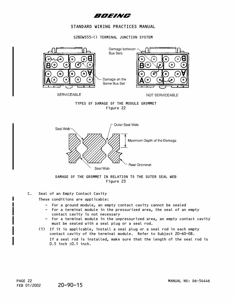
TYPES OF DAMAGE OF THE MODULE GROMMETFigure 22
DAMAGE OF THE GROMMET IN RELATION TO THE OUTER SEAL WEBFigure 23
C. Seal of an Empty Contact Cavity
These conditions are applicable:
- For a ground module, an empty contact cavity cannot be sealed- For a terminal module in the pressurized area, the seal of an empty
contact cavity is not necessary- For a terminal module in the unpressurized area, an empty contact cavity
must be sealed with a seal plug or a seal rod.
(1) If it is applicable, install a seal plug or a seal rod in each emptycontact cavity of the terminal module. Refer to Subject 20-60-08.
If a seal rod is installed, make sure that the length of the seal rod is0.5 inch ±0.1 inch.
b
STANDARD WIRING PRACTICES MANUAL
S280W555-() TERMINAL JUNCTION SYSTEM
MANUAL NO: D6-54446PAGE 22FEB 01/2002 20-90-15
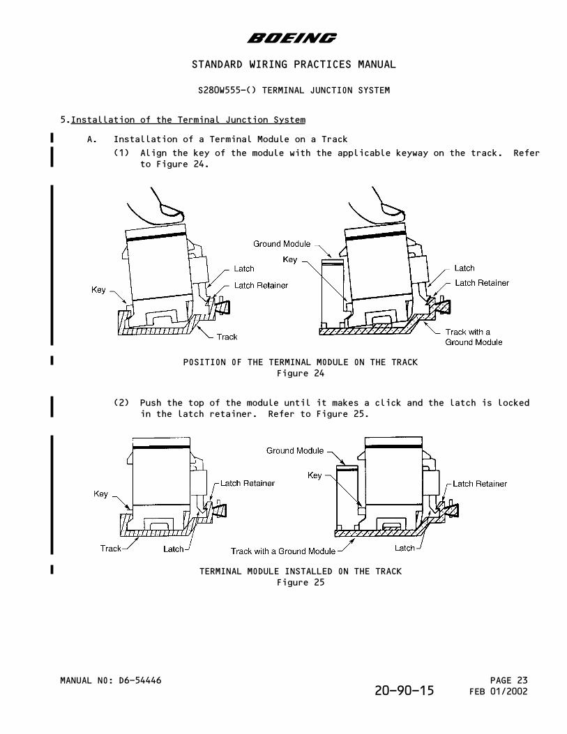
5.Installation of the Terminal Junction System
A. Installation of a Terminal Module on a Track
(1) Align the key of the module with the applicable keyway on the track. Referto Figure 24.
POSITION OF THE TERMINAL MODULE ON THE TRACKFigure 24
(2) Push the top of the module until it makes a click and the latch is lockedin the latch retainer. Refer to Figure 25.
TERMINAL MODULE INSTALLED ON THE TRACKFigure 25
b
STANDARD WIRING PRACTICES MANUAL
S280W555-() TERMINAL JUNCTION SYSTEM
MANUAL NO: D6-54446 PAGE 23FEB 01/200220-90-15
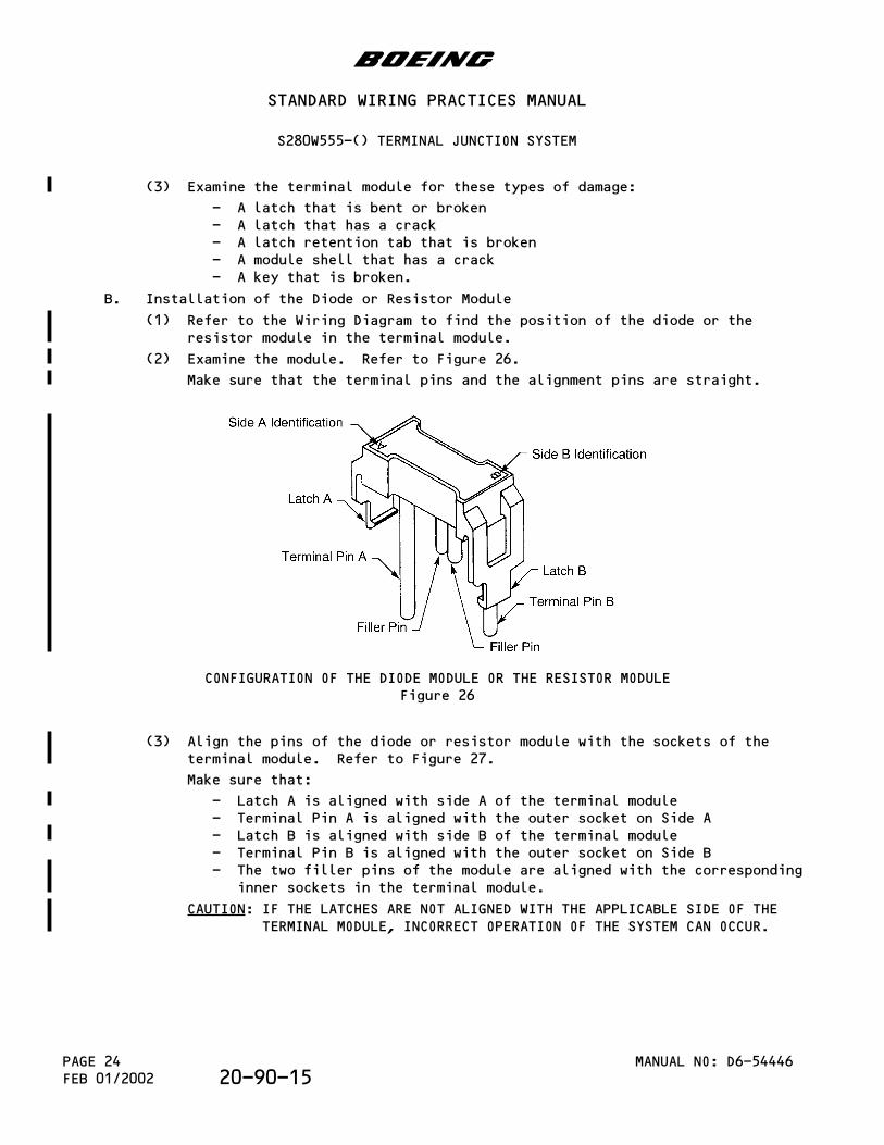
(3) Examine the terminal module for these types of damage:
- A latch that is bent or broken- A latch that has a crack- A latch retention tab that is broken- A module shell that has a crack- A key that is broken.
B. Installation of the Diode or Resistor Module
(1) Refer to the Wiring Diagram to find the position of the diode or theresistor module in the terminal module.
(2) Examine the module. Refer to Figure 26.
Make sure that the terminal pins and the alignment pins are straight.
CONFIGURATION OF THE DIODE MODULE OR THE RESISTOR MODULEFigure 26
(3) Align the pins of the diode or resistor module with the sockets of theterminal module. Refer to Figure 27.
Make sure that:
- Latch A is aligned with side A of the terminal module- Terminal Pin A is aligned with the outer socket on Side A- Latch B is aligned with side B of the terminal module- Terminal Pin B is aligned with the outer socket on Side B- The two filler pins of the module are aligned with the corresponding
inner sockets in the terminal module.
CAUTION: IF THE LATCHES ARE NOT ALIGNED WITH THE APPLICABLE SIDE OF THETERMINAL MODULE, INCORRECT OPERATION OF THE SYSTEM CAN OCCUR.
b
STANDARD WIRING PRACTICES MANUAL
S280W555-() TERMINAL JUNCTION SYSTEM
MANUAL NO: D6-54446PAGE 24FEB 01/2002 20-90-15
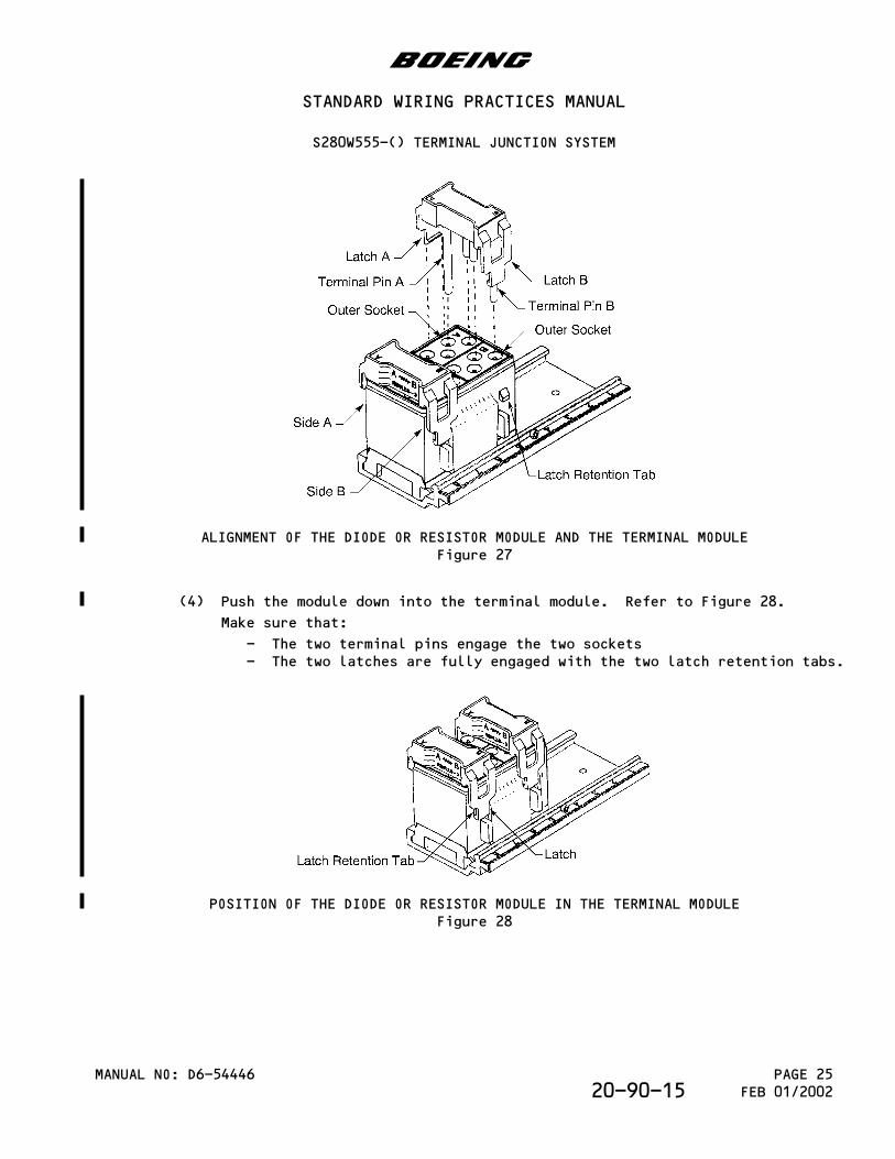
ALIGNMENT OF THE DIODE OR RESISTOR MODULE AND THE TERMINAL MODULEFigure 27
(4) Push the module down into the terminal module. Refer to Figure 28.
Make sure that:
- The two terminal pins engage the two sockets- The two latches are fully engaged with the two latch retention tabs.
POSITION OF THE DIODE OR RESISTOR MODULE IN THE TERMINAL MODULEFigure 28
b
STANDARD WIRING PRACTICES MANUAL
S280W555-() TERMINAL JUNCTION SYSTEM
MANUAL NO: D6-54446 PAGE 25FEB 01/200220-90-15
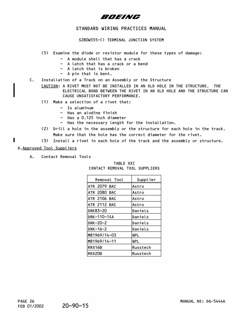
(5) Examine the diode or resistor module for these types of damage:
- A module shell that has a crack- A latch that has a crack or a bend- A latch that is broken- A pin that is bent.
C. Installation of a Track on an Assembly or the Structure
CAUTION: A RIVET MUST NOT BE INSTALLED IN AN OLD HOLE IN THE STRUCTURE. THEELECTRICAL BOND BETWEEN THE RIVET IN AN OLD HOLE AND THE STRUCTURE CANCAUSE UNSATISFACTORY PERFORMANCE.
(1) Make a selection of a rivet that:
- Is aluminum- Has an alodine finish- Has a 0.125 inch diameter- Has the necessary length for the installation.
(2) Drill a hole in the assembly or the structure for each hole in the track.
Make sure that the hole has the correct diameter for the rivet.
(3) Install a rivet in each hole of the track and the assembly or structure.
6.Approved Tool Suppliers
A. Contact Removal Tools
TABLE XXICONTACT REMOVAL TOOL SUPPLIERS
Removal Tool Supplier
ATR 2079 BAC Astro
ATR 2080 BAC Astro
ATR 2106 BAC Astro
ATR 2112 BAC Astro
DRK83-20 Daniels
DRK-110-1SA Daniels
DRK-20-2 Daniels
DRK-16-2 Daniels
M81969/14-03 QPL
M81969/14-11 QPL
RRX16B Russtech
RRX20B Russtech
b
STANDARD WIRING PRACTICES MANUAL
S280W555-() TERMINAL JUNCTION SYSTEM
MANUAL NO: D6-54446PAGE 26FEB 01/2002 20-90-15
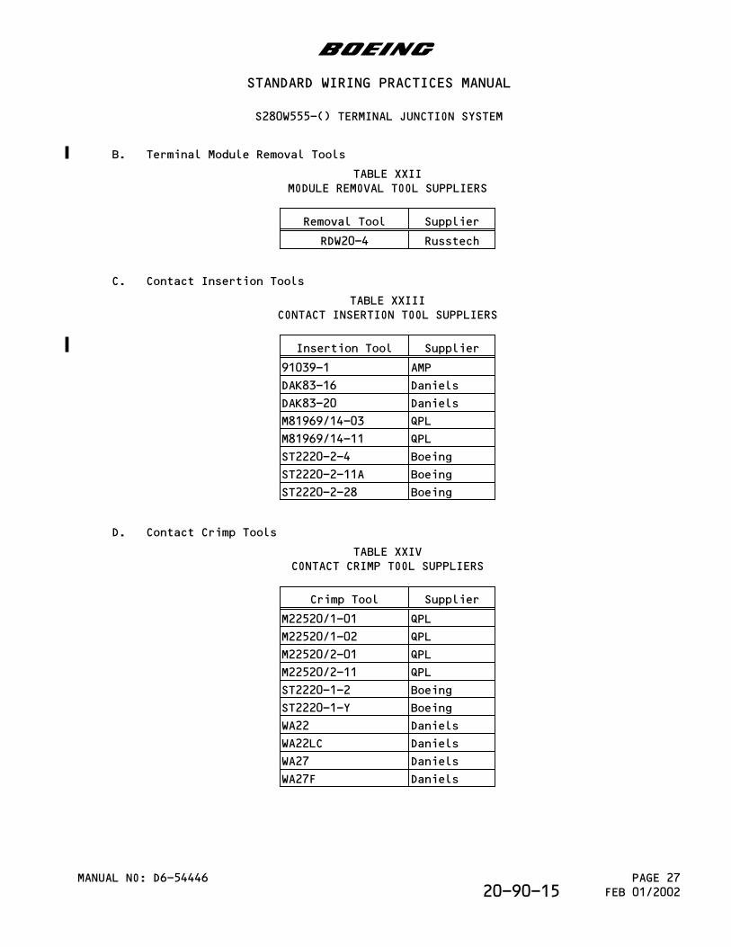
B. Terminal Module Removal Tools
TABLE XXIIMODULE REMOVAL TOOL SUPPLIERS
Removal Tool Supplier
RDW20-4 Russtech
C. Contact Insertion Tools
TABLE XXIIICONTACT INSERTION TOOL SUPPLIERS
Insertion Tool Supplier
91039-1 AMP
DAK83-16 Daniels
DAK83-20 Daniels
M81969/14-03 QPL
M81969/14-11 QPL
ST2220-2-4 Boeing
ST2220-2-11A Boeing
ST2220-2-28 Boeing
D. Contact Crimp Tools
TABLE XXIVCONTACT CRIMP TOOL SUPPLIERS
Crimp Tool Supplier
M22520/1-01 QPL
M22520/1-02 QPL
M22520/2-01 QPL
M22520/2-11 QPL
ST2220-1-2 Boeing
ST2220-1-Y Boeing
WA22 Daniels
WA22LC Daniels
WA27 Daniels
WA27F Daniels
b
STANDARD WIRING PRACTICES MANUAL
S280W555-() TERMINAL JUNCTION SYSTEM
MANUAL NO: D6-54446 PAGE 27FEB 01/200220-90-15

This page is intentionally left blank
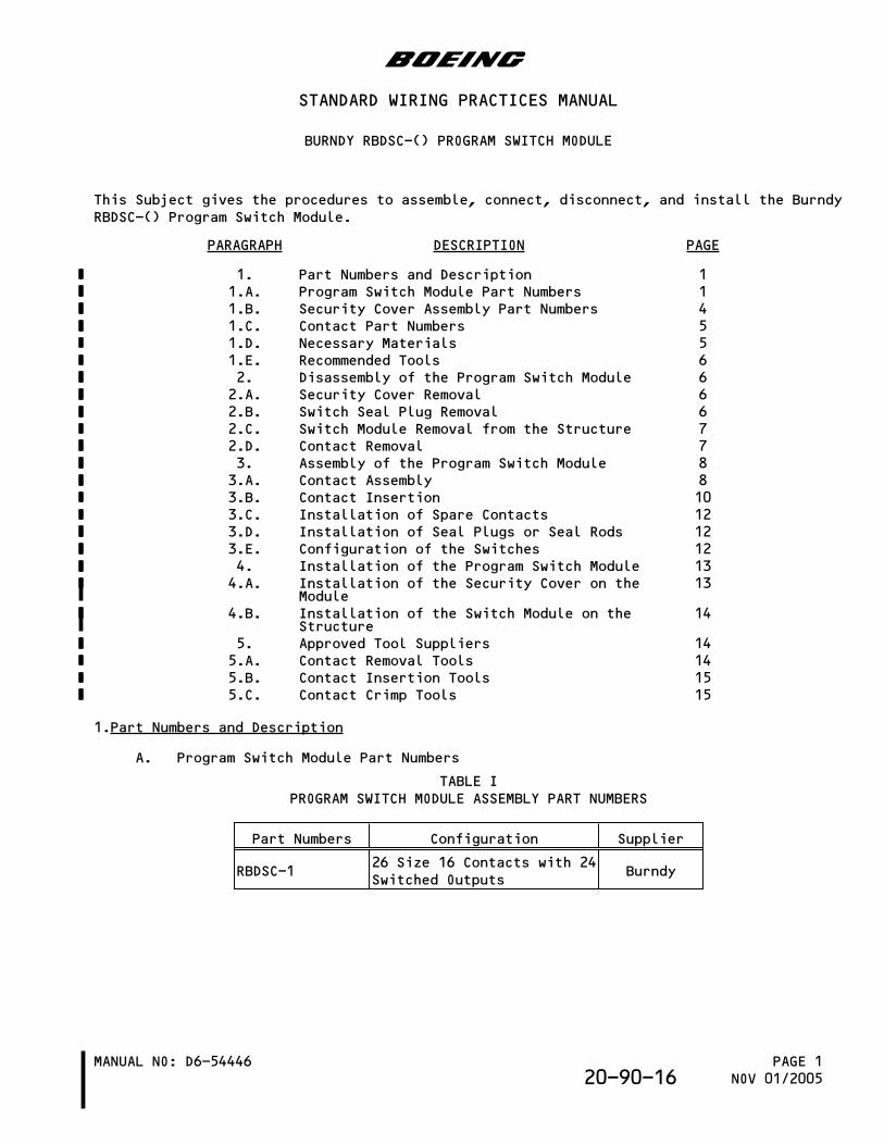
This Subject gives the procedures to assemble, connect, disconnect, and install the BurndyRBDSC-() Program Switch Module.
PARAGRAPH DESCRIPTION PAGE
1. Part Numbers and Description 11.A. Program Switch Module Part Numbers 11.B. Security Cover Assembly Part Numbers 41.C. Contact Part Numbers 51.D. Necessary Materials 51.E. Recommended Tools 62. Disassembly of the Program Switch Module 62.A. Security Cover Removal 62.B. Switch Seal Plug Removal 62.C. Switch Module Removal from the Structure 72.D. Contact Removal 73. Assembly of the Program Switch Module 83.A. Contact Assembly 83.B. Contact Insertion 103.C. Installation of Spare Contacts 123.D. Installation of Seal Plugs or Seal Rods 123.E. Configuration of the Switches 124. Installation of the Program Switch Module 134.A. Installation of the Security Cover on the
Module13
4.B. Installation of the Switch Module on theStructure
14
5. Approved Tool Suppliers 145.A. Contact Removal Tools 145.B. Contact Insertion Tools 155.C. Contact Crimp Tools 15
1.Part Numbers and Description
A. Program Switch Module Part Numbers
TABLE IPROGRAM SWITCH MODULE ASSEMBLY PART NUMBERS
Part Numbers Configuration Supplier
RBDSC-126 Size 16 Contacts with 24Switched Outputs
Burndy
b
STANDARD WIRING PRACTICES MANUAL
BURNDY RBDSC-() PROGRAM SWITCH MODULE
MANUAL NO: D6-54446 PAGE 1NOV 01/200520-90-16
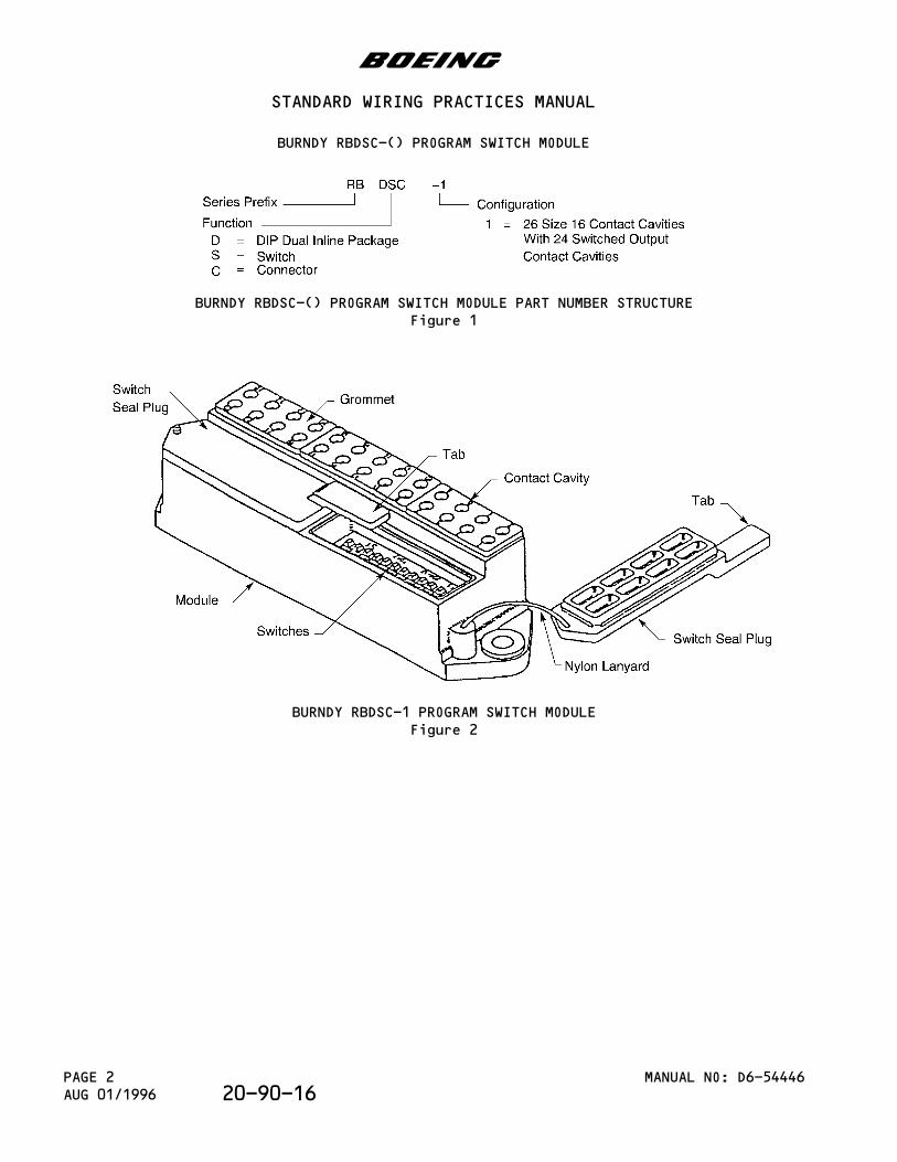
BURNDY RBDSC-() PROGRAM SWITCH MODULE PART NUMBER STRUCTUREFigure 1
BURNDY RBDSC-1 PROGRAM SWITCH MODULEFigure 2
b
STANDARD WIRING PRACTICES MANUAL
BURNDY RBDSC-() PROGRAM SWITCH MODULE
MANUAL NO: D6-54446PAGE 2AUG 01/1996 20-90-16
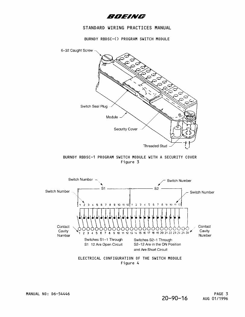
BURNDY RBDSC-1 PROGRAM SWITCH MODULE WITH A SECURITY COVERFigure 3
ELECTRICAL CONFIGURATION OF THE SWITCH MODULEFigure 4
b
STANDARD WIRING PRACTICES MANUAL
BURNDY RBDSC-() PROGRAM SWITCH MODULE
MANUAL NO: D6-54446 PAGE 3AUG 01/199620-90-16
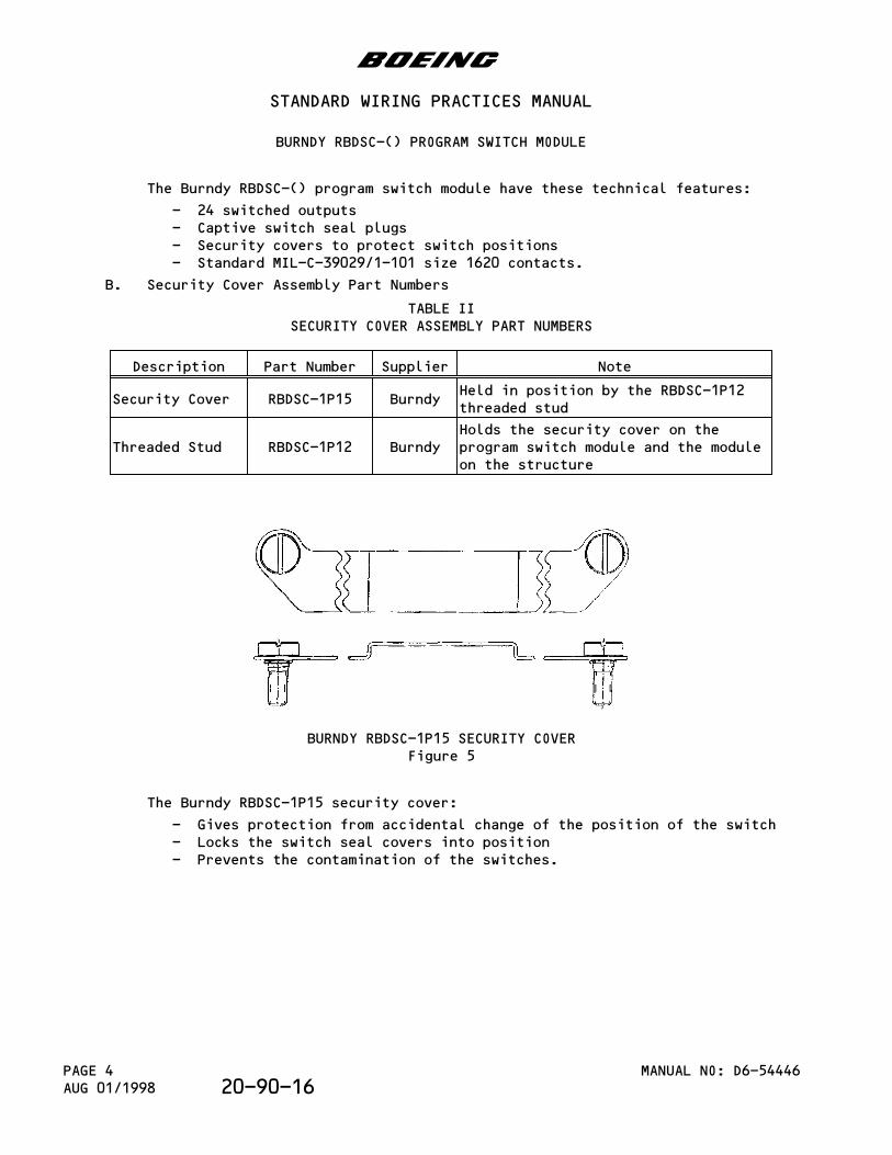
The Burndy RBDSC-() program switch module have these technical features:
- 24 switched outputs- Captive switch seal plugs- Security covers to protect switch positions- Standard MIL-C-39029/1-101 size 1620 contacts.
B. Security Cover Assembly Part Numbers
TABLE IISECURITY COVER ASSEMBLY PART NUMBERS
Description Part Number Supplier Note
Security Cover RBDSC-1P15 BurndyHeld in position by the RBDSC-1P12threaded stud
Threaded Stud RBDSC-1P12 BurndyHolds the security cover on theprogram switch module and the moduleon the structure
BURNDY RBDSC-1P15 SECURITY COVERFigure 5
The Burndy RBDSC-1P15 security cover:
- Gives protection from accidental change of the position of the switch- Locks the switch seal covers into position- Prevents the contamination of the switches.
b
STANDARD WIRING PRACTICES MANUAL
BURNDY RBDSC-() PROGRAM SWITCH MODULE
MANUAL NO: D6-54446PAGE 4AUG 01/1998 20-90-16
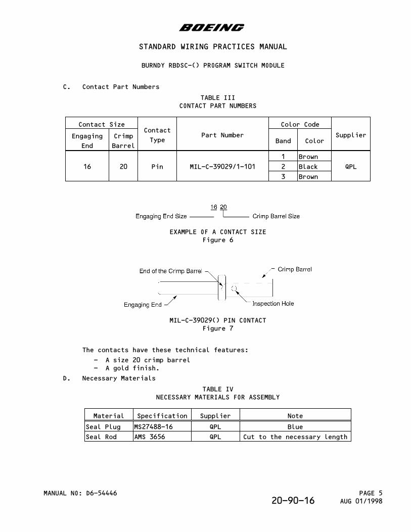
C. Contact Part Numbers
TABLE IIICONTACT PART NUMBERS
Contact SizeContact
TypePart Number
Color Code
SupplierEngaging
End
Crimp
BarrelBand Color
16 20 Pin MIL-C-39029/1-101
1 Brown
QPL2 Black
3 Brown
EXAMPLE OF A CONTACT SIZEFigure 6
MIL-C-39029() PIN CONTACTFigure 7
The contacts have these technical features:
- A size 20 crimp barrel- A gold finish.
D. Necessary Materials
TABLE IVNECESSARY MATERIALS FOR ASSEMBLY
Material Specification Supplier Note
Seal Plug MS27488-16 QPL Blue
Seal Rod AMS 3656 QPL Cut to the necessary length
b
STANDARD WIRING PRACTICES MANUAL
BURNDY RBDSC-() PROGRAM SWITCH MODULE
MANUAL NO: D6-54446 PAGE 5AUG 01/199820-90-16
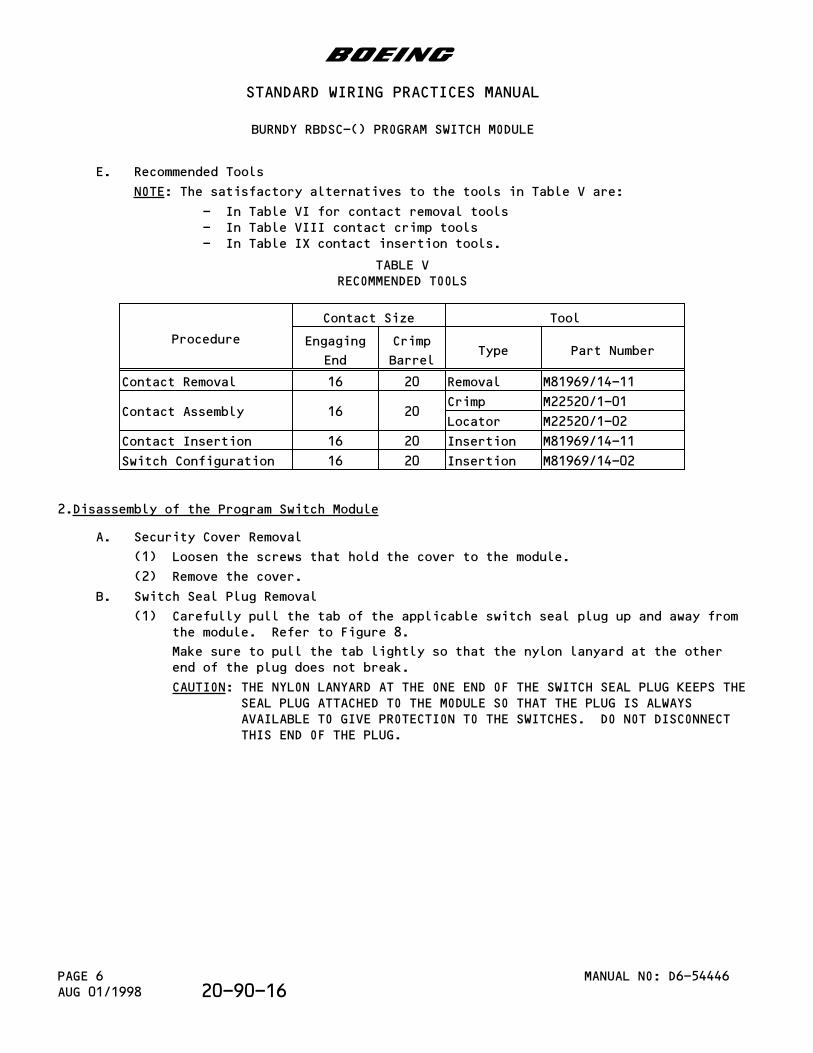
E. Recommended Tools
NOTE: The satisfactory alternatives to the tools in Table V are:
- In Table VI for contact removal tools- In Table VIII contact crimp tools- In Table IX contact insertion tools.
TABLE VRECOMMENDED TOOLS
Procedure
Contact Size Tool
Engaging
End
Crimp
BarrelType Part Number
Contact Removal 16 20 Removal M81969/14-11
Contact Assembly 16 20Crimp M22520/1-01
Locator M22520/1-02
Contact Insertion 16 20 Insertion M81969/14-11
Switch Configuration 16 20 Insertion M81969/14-02
2.Disassembly of the Program Switch Module
A. Security Cover Removal
(1) Loosen the screws that hold the cover to the module.
(2) Remove the cover.
B. Switch Seal Plug Removal
(1) Carefully pull the tab of the applicable switch seal plug up and away fromthe module. Refer to Figure 8.
Make sure to pull the tab lightly so that the nylon lanyard at the otherend of the plug does not break.
CAUTION: THE NYLON LANYARD AT THE ONE END OF THE SWITCH SEAL PLUG KEEPS THESEAL PLUG ATTACHED TO THE MODULE SO THAT THE PLUG IS ALWAYSAVAILABLE TO GIVE PROTECTION TO THE SWITCHES. DO NOT DISCONNECTTHIS END OF THE PLUG.
b
STANDARD WIRING PRACTICES MANUAL
BURNDY RBDSC-() PROGRAM SWITCH MODULE
MANUAL NO: D6-54446PAGE 6AUG 01/1998 20-90-16