5700 WOOD STOVE C US OMNI-Test Laboratories,...
32
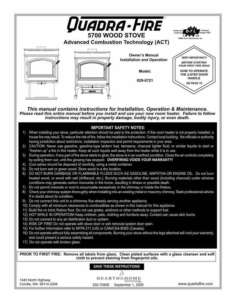
IMPORTANT SAFETY NOTES: 1) When installing your stove, particular attention should be paid to fire protection. If this room heater is not properly installed, a house fire may result. To reduce the risk of fire, follow the installation instructions. Contact local building, fire officials or authority having jurisdiction about restrictions, installation inspection and permit requirements in your area. 2) CAUTION: Never use gasoline, gasoline-type lantern fuel, kerosene, charcoal lighter fluid, or similar liquids to start or “freshen up” a fire in this heater. Keep all such liquids well away from the heater while it is in use. 3) During operation, if any part of the stove starts to glow, the stove is in an overfired condition. Close the air controls completely by pulling them out, until the glowing has stopped. OVERFIRING VOIDS YOUR WARRANTY! 4) Cool ashes should be disposed of carefully, using a metal container. 5) Do not burn wet or green wood. Store wood in a dry location. 6) DO NOT bUrN gArbAge Or FLAMMAbLe FLUIDS SUCH AS gASOLINe, NAPHTHA Or eNgINe OIL. Do not burn treated wood, or wood with salt (driftwood, etc.). burning materials other than wood (including charcoal) under adverse conditions may generate carbon monoxide in the home, resulting in illness or possible death. 7) Do not permit creosote or soot to accumulate excessively in the chimney or inside the firebox. 8) Check your chimney system thoroughly when installing into an existing metal or masonry chimney. Seek professional advice if in doubt about its condition. 9) Do not connect this unit to a chimnney flue already serving another appliance. 10) Comply with all minimum clearances to combustibles as shown in this manual for this appliance. 11) build fire on brick firebox floor. Do not use grates, andirons or other methods to support fuel. 12) HOT WHILe IN OPerATION! Keep children, pets, clothing and furniture away. Contact can cause skin burns. 13) Do not connect to any air distribution duct or system. 14) rISK OF FIre! Do not operate with stove door or ash removal system door open. 15) For further information refer to NFPA 211 (US) or CAN/CSA-b365 (Canada). 16) Do not operate without fully assembling all components. burning your stove wthout the legs attached will void your warranty, and could present a serious safety hazard. 17) Do not operate with broken glass. VERY IMPORTANT!! BEFORE STARTING YOUR FIRST FIRE READ HOW TO OPERATE THE 2-STEP DOOR HANDLE ON PAGE 19 Owner’s Manual Installation and Operation Model: 820-0721 SAVE THESE INSTRUCTIONS www.quadrafire.com This manual contains instructions for Installation, Operation & Maintenance. Please read this entire manual before you install and use your new room heater. Failure to follow instructions may result in property damage, bodily injury, or even death. 5700 WOOD STOVE Advanced Combustion Technology (ACT) O-T L Tested and Listed by Portland Oregon USA OMNI-Test Laboratories, Inc. C US 250-7090e September 1, 2008 PRIOR TO FIRST FIRE: Remove all labels from glass. Clean plated surfaces with a glass cleanser and soft cloth to prevent staining from fingerprint oils. 1445 North Highway Colville, WA 99114-2008 R
-
Upload
truonghanh -
Category
Documents
-
view
213 -
download
0
Transcript of 5700 WOOD STOVE C US OMNI-Test Laboratories,...
IMPORTANT SAFETY NOTES:1) When installing your stove, particular attention should be paid to fire protection. If this room heater is not properly installed, a
house fire may result. To reduce the risk of fire, follow the installation instructions. Contact local building, fire officials or authority having jurisdiction about restrictions, installation inspection and permit requirements in your area.
2) CAUTION: Never use gasoline, gasoline-type lantern fuel, kerosene, charcoal lighter fluid, or similar liquids to start or “freshen up” a fire in this heater. Keep all such liquids well away from the heater while it is in use.
3) During operation, if any part of the stove starts to glow, the stove is in an overfired condition. Close the air controls completely by pulling them out, until the glowing has stopped. OVERFIRING VOIDS YOUR WARRANTY!
4) Cool ashes should be disposed of carefully, using a metal container.5) Do not burn wet or green wood. Store wood in a dry location.6) DO NOT bUrN gArbAge Or FLAMMAbLe FLUIDS SUCH AS gASOLINe, NAPHTHA Or eNgINe OIL. Donotburn
treated wood, or wood with salt (driftwood, etc.). burning materials other than wood (including charcoal) under adverse conditions may generate carbon monoxide in the home, resulting in illness or possible death.
7) Do not permit creosote or soot to accumulate excessively in the chimney or inside the firebox.8) Check your chimney system thoroughly when installing into an existing metal or masonry chimney. Seek professional advice
if in doubt about its condition.9) Do not connect this unit to a chimnney flue already serving another appliance.10) Comply with all minimum clearances to combustibles as shown in this manual for this appliance.11) build fire on brick firebox floor. Do not use grates, andirons or other methods to support fuel.12) HOT WHILe IN OPerATION! Keep children, pets, clothing and furniture away. Contact can cause skin burns.13) Do not connect to any air distribution duct or system.14) rISK OF FIre! Do not operate with stove door or ash removal system door open.15) For further information refer to NFPA 211 (US) or CAN/CSA-b365 (Canada).16) Do not operate without fully assembling all components. burning your stove wthout the legs attached will void your warranty,
and could present a serious safety hazard.17) Do not operate with broken glass.
VERY IMPORTANT!!
BEFORE STARTING YOUR FIRST FIRE READ
HOW TO OPERATE THE 2-STEP DOOR
HANDLE ON PAGE 19
Owner’s Manual Installation and Operation
Model:
820-0721
SAVE THESE INSTRUCTIONS
www.quadrafire.com
This manual contains instructions for Installation, Operation & Maintenance.Please read this entire manual before you install and use your new room heater. Failure to follow
instructions may result in property damage, bodily injury, or even death.
5700 WOOD STOVEAdvanced Combustion Technology (ACT)
O-T LTested and Listed by
PortlandOregon USA
OMNI-Test Laboratories, Inc.C US
250-7090e September 1, 2008
PRIOR TO FIRST FIRE: Remove all labels from glass. Clean plated surfaces with a glass cleanser and soft cloth to prevent staining from fingerprint oils.
1445 North HighwayColville, WA 99114-2008
R
5700 ACT Wood Stove
Page 2 September 1, 2008
R
250-7090e
and Welcome to the Quadra-Fire Family!
Hearth & Home Technologies welcomes you to our tradition of excellence! In choosing a Quadra-Fire appliance, you have our assurance of commitment to quality, durability, and perfor-mance.
This commitment begins with our research of the market, including ‘Voice of the Customer’ contacts, ensuring we make products that will satisfy your needs. Our research and Devel-opment facility then employs the world’s most advanced tech-
nology to achieve the optimum operation of our stoves, inserts and fireplaces. And yet we are old-fashioned when it comes to crafts-manship. each unit is meticulously fabricated and surfaces are hand-finished for lasting beauty and enjoyment. Our pledge to qual-ity is completed as each model undergoes a quality control inspec-tion. We wish you and your family many years of enjoyment in the warmth and comfort of your hearth appliance. Thank you for choos-ing Quadra-Fire.
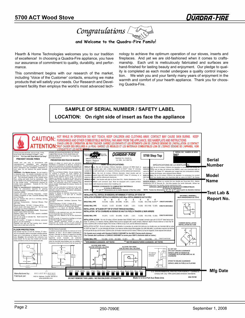
SAMPLE OF SERIAL NUMBER / SAFETY LABELLOCATION: On right side of insert as face the appliance
Model Name
Serial Number
Test Lab & Report No. A B C D E F G H
SINGLE WALL PIPE 12.5 (318) 8 (203) 25.5 (648) 15 (381) 2 (51) 13 (330) 45.5 (1156) 18 (457)**DOUBLE WALL PIPE 9.5 (241) 5 (127) 25.5 (648) 15 (381) 2 (51) 13 (330) 45.5 (1156) 12 (305)
DOUBLE WALL PIPE 9.5 (241) 5 (127) 25.5 (648) 15 (381) 2 (51) 13 (330) 45.5 (1156) 12 (305)
INSTALLATION: ALCOVE - Six inch (6 inches) (152mm) diameter listed DOUBLE WALL air insulated connector pipe with UL103 HT* listed factory-built Class "A" chimney, or a masonry chimney. (Mobile Home must be equipped with a spark arrestor.) Maximum depth of Alcove shall be no more than 48 inches (1220mm) with a minimum height of 45.5 inches (1156mm) to top of unit, and the referenced clearances.
(*In Canada must comply with Standard CAN/ULC-S629-M87 for the 650oC Factory-built chimney.)(*Au Canada doit conformer a CAN/ULC-S629-M87 la norme pour 650oC cheminée bâtit en usine.)
DOUBLE WALL PIPE 10.5 (268) 6 (153) 25.5 (648) 15 (381) N/A N/A 45.5 (1156) *** **NFPA MINIMUM CLEARANCES - NOT TESTED *** SEE PIPE MANUFACTURERS CLEARANCES - NOT TESTED
SPÉCIFICATIONS DE LA VENTILATION:MUR SIMPLE: De six (6 inches) (152mm) de diamètre le connecteur de conduit de minimum d'acier noir ou bleu de minimum de 24MSG, avec une cheminée bâtit en usine UL103HT* de Classe "A", adéquate pour usage avec les combustions solides, ou une cheminée de briques, avec espaces libres référés.MUR DOUBLE: De six (6 inches) (152mm) de diamètre, le connecteur du conduit d'air isolé pour mur double avec une cheminée bâtit en usine UL103HT* de Classe "A:, ou une cheminée de briques, avec espaces libres alloués.MAISON MOBILE: Utiliser un conduit de mur double par Dura-Vent DVL, Selkirk Metalbestos DS ou Security DL. Doit être équipé d'un arrêt d'étincelle. Utiliser les espaces libres pour mur double comme mentionné ci-bas.
MINIMUM CLEARANCES TO COMBUSTIBLE MATERIALS: In Inches & (Millimeters)
NOTE: All "A" , "C" and "F" Dimensions are to inside diameter of the flue collar.
LISTED ROOM HEATER, SOLID FUEL TYPE. ALSO FOR USE IN MOBILE HOMES. (UM) 84-HUD . "For Use with Solid Wood Fuel Only"
1445 N. Highway, Colville, WA 99114www.quadrafire.com
Install and use only in accordance with manufacturer's installation and operating instructions. Contact local building or fire officials about restrictions and installation inspections in your area. Do not obstruct the space beneath heater.WARNING - For Mobile Homes: Do not install in a sleeping room. An outside combustion air inlet must be provided and unrestricted while unit is in use. The structural integrity of the mobile home floor, ceiling and walls must be maintained. The stove needs to be properly grounded to the frame of the mobile home. Components required for mobile home installation: Outside Air Kit, Part Number 831-1780.Refer to manufacturer's instructions and local codes for precautions required for passing chimney through a combustible wall or ceiling and maximum offsets.Inspect and clean chimney frequently - Under Certain Conditions of Use, Creosote Buildup May Occur Rapidly.Do not connect this unit to a chimney serving another appliance.Optional Components: Optional Blower, Part 831-1701.Electrical Rating: 115 VAC, 1.2 Amps, 60 Hz.Route power cord away from unit. Do not route cord over or in front of appliance.DANGER: Risk of electrical shock. Disconnect power supply before servicing.Replace glass only with 5mm ceramic available from your dealer.Do not use grate or elevate fire. Build wood fire directly on hearth.Do not overfire - if heater or chimney connector glows, you are overfiring.Operate only with the fuel loading door closed. Open only to add fuel to the fire.
CAUTION:
U.S. ENVIRONMENTAL PROTECTION AGENCY - Certified to comply with July 1990 particulate emission standards.
2007 2008 2009 Jan. Feb. Mar. Apr. May June July Aug. Sept. Oct. Nov. Dec.
PREVENT HOUSE FIRES
FLOOR PROTECTION:Floor protector must be a 1/2 inch min. thickness, ("k" value = .84) non-combustible material or equivalent, extending beneath heater and to front/sides/rear as indicated on the diagram below. Exception: Non-combustible floor protections must extend beneath the flue pipe when installed with horizontal venting and extend 2 inches (51mm) beyond each side.
O-T LTested and Listed by
BeavertonOregon USA
OMNI-Test Laboratories, Inc.C
Report / Rapport#061-S-38-2
TESTED TO:/ TESTÉ À: UL 1482, ULC S627-93
HOT WHILE IN OPERATION DO NOT TOUCH, KEEP CHILDREN AND CLOTHING AWAY. CONTACT MAY CAUSE SKIN BURNS. KEEP FURNISHINGS AND OTHER COMBUSTIBLE MATERIAL FAR AWAY FROM THE APPLIANCE. SEE NAMEPLATE AND INSTRUCTIONS
VENT SPECIFICATIONS:SINGLE WALL: Six inch (6 inches) (152mm) diameter, minimum 24 MSG black or blued steel connector pipe, with a listed factory-built UL103HT* Class "A" chimney, suitable for use with solid fuels, or a masonry chimney, and the referenced clearances.DOUBLE WALL: Six inch (6 inches) (152mm) diameter, listed double wall air insulated connector pipe with listed factory-built UL103HT* Class "A" chimney, or a masonry chimney and the referenced clearancesMOBILE HOME: Use double wall pipe by Dura-Vent DVL, Selkirk Metalbestos DS or Security DL double wall connector pipe. Must be equipped with a spark arrestor. Apply double wall clearances below when installing unit.
5700 Step TopR
250-7072E
CHAUD LORS DE L'OPÉRATION. NE PAS TOUCHER. GARDEZ LES ENFANTS ET LES VÊTEMENTS LOIN DE L'ESPACE DÉSIGNÉ DE L'INSTALLATION. LE CONTACT PEUT CAUSER DES BRÛLURES À LA PEAU. GARDEZ LES MEUBLES ET LES MATÉRIAUX COMBUSTIBLES LOIN DE L'ESPACE DÉSIGNÉ DE L'APPAREIL. VOIR L'ÉTIQUETTE ET LES INSTRUCTIONS.
ATTENTION:APPAREIL DE CHAUFFAGE DE PIÈCE, DE TYPE DE COMBUSTIBLE SOLIDE, POUR USAGE DANS LES MAISONS MOBILES. (UM) 84 HUD. "Pour Usage Avec Bois Solide Seulement"
Installez et utilisez en accord avec les instructions d'installation et d'opération du fabricant. Contactez le bureau de la construction ou le bureau des incendies au sujet des restrictions et des inspections d'installation dans votre voisinage. Ne pas obstruez l'espace en dessous de l'appareil.AVIS - Pour Les Maisons Mobiles: Ne pas installer dans une chambre à coucher. Un tuyau extérieur de combustion d'air doit être installé et ne doit pas être obstrué lorsque l'appareil est en usage. La structure intégrale du plancher, du plafond et des murs de la maison mobile doit être maintenue intacte. L'appareil de chauffage doit être fixé à la charpente de la maison mobile. Les composants requis pour l'installation des maisons mobiles: Assemblage d'air extérieur, Numéro de Pièce 831-1780.Référez vous aux instructions du fabricant et des codes locaux pour les précautions requises pour passer une cheminée à travers un mur ou un plafond combustibles, et les compensations maximums.Inspectez et nettoyez la cheminée fréquemment. Sous certaines conditions, il se peut que la créosote s'accumule rapidement.Ne pas connecter cet appareil à une cheminée servant un autre appareil.Composants Optionnels: Ventilateur Optionnel, Pièce #831-1701.Puissance Électrique: 115 VAC, 1.2 Amps, 60 Hz.Éloignez le fil électrique de l'appareil. Ne pas faire passer le fil électrique au dessus ou en dessous de l'appareil.DANGER: Il y a risque de décharge électrique. Déconnectez le fil électrique de la prise de contact avant le service.Remplacez la vitre seulement avec une vitre céramique de 5 mm disponible chez votre fournisseur.N'élevez pas le feu. Bâtissez le feu de bois directement sur l'âtre.Ne pas surchauffer. Si l'appareil de chauffage ou le tuyau de cheminée rougissent, vous surchauffez.Opérez l'appareil seulement lorsque la porte de chargement est fermée. Ouvrez la porte seulement lorsque vous devez ajouter des combustibles dans le feu.
PRÉVENTION DES FEUX DE MAISON
PROTECTION DU PLANCHER:Le protecteur de plancher doit être d'un minimum de 1/2 inch d'épaisseur, ('k" value = .84) de matériel incombustible ou équivalent, s'étendant du dessous de l'appareil de chauffage à l'avant, aux cotés et à l'arrière comme indiqué sur le diagramme suivant. Exception: Les protections incombustibles du plancher doivent s'étendre en dessous du conduit de cheminée lorsqu'installées avec une ventilation à l'horizontale et s'étendre de 2 inches (51mm) de chaque côté.
ESPACES LIBRES MINIMUM DES MATÉRIAUX COMBUSTIBLES: En Pouces & (millimètres)
NOTE: Toutes les dimensions "A", "C", et "F" sont à partir du diamètre intérieur de l'entrée du conduit.
BACKWALL/SIDEWALLMUR ARRIÈRE/MUR DE CÔTÉ
90 OFF TOP UP & OUT CEILING CLEARANCEESPACE LIBRE DU DESSUS DE L'APPAREIL AU PLAFOND AVEC 90 DE COURBURE
STOVE TO CEILING CLEARANCEESPACE LIBRE DU POÊLE AU PLAFOND
CORNER INSTALLATIONINSTALLATION DU COIN
ALCOVE TOP VIEW /VUE DU HAUT DE L'ALCÔVE
ALCOVE SIDE VIEW / VUE DE CÔTÉ DE L'ALCÔVE
DO NOT REMOVE THIS LABEL / NE PAS ENLEVER L'ÉTIQUETTE Made in U.S.A./Fait Aux États-Unis
CONDUIT DU MUR SIMPLE
CONDUIT DU MUR DOUBLE
INSTALLATION: 90o ELBOW OFF TOP OF STOVE THROUGH BACKWALLINSTALLATION: 90o DU COURBURE AU DESSUS DE HAUT DU POÊLE A TRAVERS LE MUR ARRIERE
INSTALLATION: ALCÔVE - De six (6 inches) (152mm) de diamètre, le connecteur du conduit d'air isolé pour mur double avec une cheminée bâtit en usine UL103HT de Classe "A", ou une cheminée de briques. (Les maisons mobiles doivent être équipées d'un arrêt d'étincelle). La profondeur maximum de l'alcôve ne doit pas être de plus de 48 inches (1220mm) avec une hauteur minimum de 45.5 inches (1156mm) du haut de l'appareil, et des espaces libres alloués.
CONDUIT DU MUR DOUBLE
A B
C
D
E
FE
F
GH
C
D
G
A
B16" from glass
8"
USA
Fuel loading door
3-3/16”
4-3/16”
33-5/8”minimum
44-9/16”minimum
CANADA
203mm (8")
203mm(8")
203mm(8")
457mm (18")
1387mm (54-9/16")minimum
1083mm (42-5/8")min
Manufactured by:Fabriqué par:
"G" is from top where flue is connected
INSTALLATION: FULL VERTICAL OR HORIZONTAL WITH MINIMUM 2 FT VERTICAL OFF STOVE TOPINSTALLATION: ENTIÈREMENT VERTICALE OU HORIZONTALE AVEC 609mm VERTICAL MINIMUM DU HAUT DU POÊLE
CONDUIT DU MUR DOUBLE
SERIAL NO. / NUMÉRO DE SÉRIE
007
Size: 8-1/2” x11Copy: Red & BlackBackground: SilverMaterial: Foil w/slit back
Mfg Date
Page 3September 1, 2008
5700 ACT Wood Stove R
250-7090e
TABLE OF CONTENTS
Listings & Safety Cautions.............................................4Installation Materials Needed ........................................4Venting System Overview..............................................4Dimensions ....................................................................5Locating Your Stove.......................................................5Serial Number Label Location .......................................6Clearances to Combustibles..........................................6Vent Specifications ........................................................7Floor Protection .............................................................7Alternate Materials Worksheet ......................................8
INSTALLATION METHODS:Chimney Height / Draft & 2-10-3 rule ...........................9Flue Systems & Chimney Connections .........................10Masonry Chimney..........................................................10Solid Pack with Metal Supports .....................................11-12Metal Pre-Fab Chimney.................................................13Mobile Home .................................................................14
OPERATING INSTRUCTIONS:Ash removal System ....................................................15burning Process ............................................................19Start-Up & Primary Air Systems ....................................192-Step Door Handle Instructions ...................................19Operating Instructions ...................................................20building a Fire................................................................20Opacity ..........................................................................21burn rates.....................................................................21Wood Selection .............................................................21blower Operation ...........................................................21
MAINTENANCE:Creosote removal .........................................................22Chimney Cleaning .........................................................22Ash Disposal .................................................................22Overfiring .......................................................................22Firebrick ........................................................................22glass Care & Cleaning ..................................................22Plated Surfaces .............................................................22
ACCESSSORY / PARTS REPLACEMENT Ash removal System .................................................. 15Pedestal & Leg Kit Installation ..................................... 16blower Installation ....................................................... 17Outside Air Kit .............................................................. 17brick replacement ...................................................... 23glass replacement ..................................................... 23Door Handle Assembly ................................................ 24baffle & Ceramic blanket removal & Installation ........ 24Accessory & replacement Parts List .......................... 25exploded Views ........................................................... 26Service & Maintenance Log......................................... 27-28Homeowner’s Notes .................................................... 29Warranty Policy ........................................................... 30-31Contact Information ..................................................... 32
5700 ACT Wood Stove
Page 4 September 1, 2008
R
250-7090e
LISTINGS & SAFETY CAUTIONSThese installation instructions describe the installation and opera-tion of the QUADRA-FIRE 5700 woodstove. This stove meets the U.S. environmental Protection Agency’s 1990 particulate emission standards. The 5700 is listed by OMNI-Test Laboratories, Inc. to UL Safety Standard 1482, and ULC S627-93, and (UM) 84-HUD. The 5700 is approved for mobile home installations when not installed in a sleeping room and when an outside combustion air inlet is provided. The structural integrity of the mobile home floor, ceiling, and walls must be maintained. The stove must be properly grounded to the frame of the mobile home and use only listed double-wall connector pipe. Outside Air Kit, Part 831-1780, must be installed in a mobile home installation.
Check with your local building code agency before you begin your installation to ensure compliance with local codes, including the need for permits and follow-up inspections. be sure local build-ing codes do not supersede UL specifications and always obtain a building permit so that insurance protection benefits cannot be unexpectedly cancelled. If any assistance is required during instal-lation, please contact your local dealer.
Inspect and clean vent system frequently in accordance with the instructions contained in this manual. Do not connect this unit to a chimney serving another appliance.
When using optional blower, Part 831-1701, route power cord away from unit. Do not route cord under or in front of appliance.
Do not elevate fire. build wood fire directly on firebrick.
Do not overfire - if heater or chimney connector glows, you are overfiring. Stove thermometer recommended.
Operate only with the door closed. Open only to add fuel to the fire. Operating with the door open can cause hot embers or sparks to fall out and a fire may result.
INSTALLATION MATERIALS NEEDED FOR SAFETY
CHIMNEY CONNECTOR (also known as flue pipe or stove pipe): The chimney connector joins the stove to the chimney (see page 9). It must be 6” (152mm) minimum diameter 24 MSg black or blued steel, or an approved air-insulated double wall venting pipe.
THIMBLE: A manufactured or site-constructed device installed in combustible walls through which the chimney connector passes to the chimney (see pages 12-13). It is intended to keep the walls from igniting.
CHIMNEY SYSTEMS:
A. APPrOVeD MASONrY (see specifications on page 10) with at least 5/8” (16mm) fire clay lining joined with refractory cement or other listed system suitable for use with wood stoves.
b. PreFAbrICATeD 6" (152mm) listed high temperature (UL 103 HT or ULC S629M) chimney. Components required by manufacturers for installation such as the chimney support base, firestop (as appropriate), attic insulation shield, insulated tee, etc., are necessary to assure a safe chimney installation. Use only components manufactured for the chimney. Chimney installation should meet NFPA 211 standards.
FIRE SAFETY: To provide reasonable fire safety, the following should be given serious consideration:1. Install at least one smoke detector on each floor of your home
to ensure your safety. They should be located away from the heating appliance and close to the sleeping areas. Follow the smoke detector manufacturer’s placement and installation instructions, and be sure to maintain regularly.
2. A conveniently located Class A fire extinguisher to contend with small fires resulting from burning embers.
3. A practiced evacuation plan, consisting of at least two escape routes.
4. A plan to deal with a chimney fire as follows:
In the event of a chimney fire:
a. Immediately evacuate the home.b. Notify fire department
VENTING SYSTEMThe venting system consists of a chimney connector and a chimney. These get extremely hot during use. Temperatures inside the chimney may exceed 2000°F (1100°C) in the event of a creosote fire. To protect against the possibility of a house fire, the chimney connector and chimney must be properly installed and maintained. An approved thimble must be used when a connection is made through a combustible wall to a chimney. A chimney support package must be used when a connection is made through the ceiling to a prefabricated chimney. These accessories are absolutely necessary to provide safe clearances to combustible wall and ceiling material. Follow venting manufacturer’s clearances when installing venting system.
This stove may be connected to a lined masonry chimney or a Listed high temperature prefabricated approved metal chimney. Do not connect it to a chimney serving another appliance. To do so will affect the safe operation of both appliances.
WARNING! DO NOT ATTEMPT TO OPERATE THIS WOODSTOVE WITHOUT READING AND UNDERSTANDING THESE OPERAT-ING INSTRUCTIONS THOROUGHLY. FAILURE TO OPERATE THIS APPLIANCE PROPERLY MAY CAUSE A HOUSE FIRE.
WARNING! NEVER DRAW OUTSIDE COMBUSTION AIR FROM A WALL, FLOOR OR CEILING CAVITY OR FROM ANY ENCLOSED SPACE SUCH AS AN ATTIC OR GARAGE.
WARNING! THIS APPLIANCE IS HOT WHILE IN OPERATION AND MAY REMAIN SO UP TO 40 MINUTES AFTER THERE IS NO FUEL IN THE FIREBOX. IF THIS APPLIANCE IS IN A HIGH TRAFFIC AREA OR CHILDREN MAY BE NEAR IT IS RECOM-MENDED THAT YOU PURCHASE A DECORATIVE BARRIOR TO GO IN FRONT OF THE APPLIANCE. ALWAYS kEEP CHILDREN AWAY WHILE IT IS OPERATING AND DO NOT LET ANYONE OPERATE THIS APPLIANCE UNLESS THEY ARE FAMILIAR WITH THESE OPERATION INSTRUCTIONS.
Page 5September 1, 2008
5700 ACT Wood Stove R
250-7090e
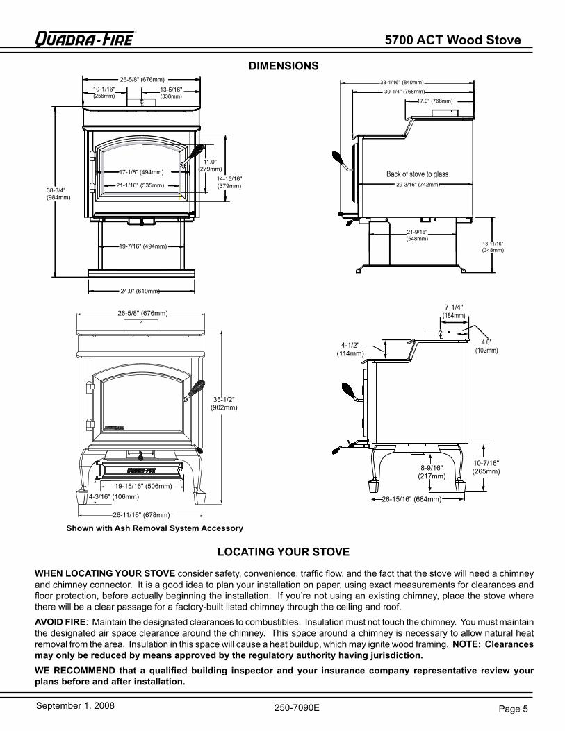
DIMENSIONS
Shown with Ash Removal System Accessory
CL
26-5/8" (676mm)10-1/16"(256mm)
13-5/16"(338mm)
21-1/16" (535mm)14-15/16"(379mm)
11.0"(279mm)17-1/8" (494mm)
19-7/16" (494mm)
24.0" (610mm)
38-3/4"(984mm)
back of stove to glass
13-11/16" (348mm)
21-9/16"(548mm)
29-3/16" (742mm)
17.0" (768mm)
33-1/16" (840mm)
30-1/4" (768mm)
26-5/8" (676mm)
35-1/2" (902mm)
19-15/16" (506mm)4-3/16" (106mm)
26-11/16" (678mm)
26-15/16" (684mm)
8-9/16" (217mm)
10-7/16" (265mm)
4-1/2" (114mm)
CL
7-1/4" (184mm)
4.0" (102mm)
LOCATING YOUR STOVE
WHEN LOCATING YOUR STOVE consider safety, convenience, traffic flow, and the fact that the stove will need a chimney and chimney connector. It is a good idea to plan your installation on paper, using exact measurements for clearances and floor protection, before actually beginning the installation. If you’re not using an existing chimney, place the stove where there will be a clear passage for a factory-built listed chimney through the ceiling and roof. AVOID FIRE: Maintain the designated clearances to combustibles. Insulation must not touch the chimney. You must maintain the designated air space clearance around the chimney. This space around a chimney is necessary to allow natural heat removal from the area. Insulation in this space will cause a heat buildup, which may ignite wood framing. NOTE: Clearances may only be reduced by means approved by the regulatory authority having jurisdiction.WE RECOMMEND that a qualified building inspector and your insurance company representative review your plans before and after installation.
5700 ACT Wood Stove
Page 6 September 1, 2008
R
250-7090e
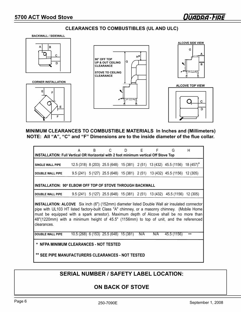
CLEARANCES TO COMBUSTIBLES (UL AND ULC)
A b
C
D
BACkWALL / SIDEWALL
e
Fe
F
CORNER INSTALLATION
g
H*90° OFF TOP UP & OUT CEILING CLEARANCE
STOVE TO CEILING CLEARANCE
C
D
ALCOVE TOP VIEW
MINIMUM CLEARANCES TO COMBUSTIBLE MATERIALS In Inches and (Millimeters)NOTE: All “A”, “C” and “F” Dimensions are to the inside diameter of the flue collar.
A b C D e F g H INSTALLATION: Full Vertical OR Horizontal with 2 foot minimum vertical Off Stove Top
SINGLE WALL PIPE 12.5 (318) 8 (203) 25.5 (648) 15 (381) 2 (51) 13 (432) 45.5 (1156) 18 (457)*
DOUBLE WALL PIPE 9.5 (241) 5 (127) 25.5 (648) 15 (381) 2 (51) 13 (432) 45.5 (1156) 12 (305)
INSTALLATION: 90o ELBOW OFF TOP OF STOVE THROUGH BACkWALL
DOUBLE WALL PIPE 9.5 (241) 5 (127) 25.5 (648) 15 (381) 2 (51) 13 (432) 45.5 (1156) 12 (305)
INSTALLATION: ALCOVESix inch (6") (152mm) diameter listedDoubleWallairinsulatedconnectorpipe with UL103 HT listed factory-built Class "A" chimney, or a masonry chimney. (Mobile Homemust be equipped with a spark arrestor). Maximum depth of Alcove shall be no more than48"(1220mm) with a minimum height of 45.5" (1156mm) to top of unit, and the referencedclearances.
DOUBLE WALL PIPE 10.5 (268) 6 (153) 25.5 (648) 15 (381) N/A N/A 45.5 (1156) **
* NFPA MINIMUM CLEARANCES - NOT TESTED
** SEE PIPE MANUFACTURERS CLEARANCES - NOT TESTED
gA
B
ALCOVE SIDE VIEW
SERIAL NUMBER / SAFETY LABEL LOCATION:
ON BACk OF STOVE
Page 7September 1, 2008
5700 ACT Wood Stove R
250-7090e
FLOOR PROTECTION
16" from glass8"
USA
Fuel loading door
3-3/16"
4-13/16"
44-9/16"minimum
33-5/8" minimum
CANADA
203mm (8")
203mm(8")
203mm(8")
457mm (18")
1387mm (54-9/16")minimum
1083mm (42-5/8")minimum
52-13/16 in.
33-5/
8 in.
44-7/
8 in.
29-5/
16 in
.
3-1/16
in.
32-1/16 in.
135°
optio
nal
cove
rage
must extend 2" beyond each side of pipe
USA
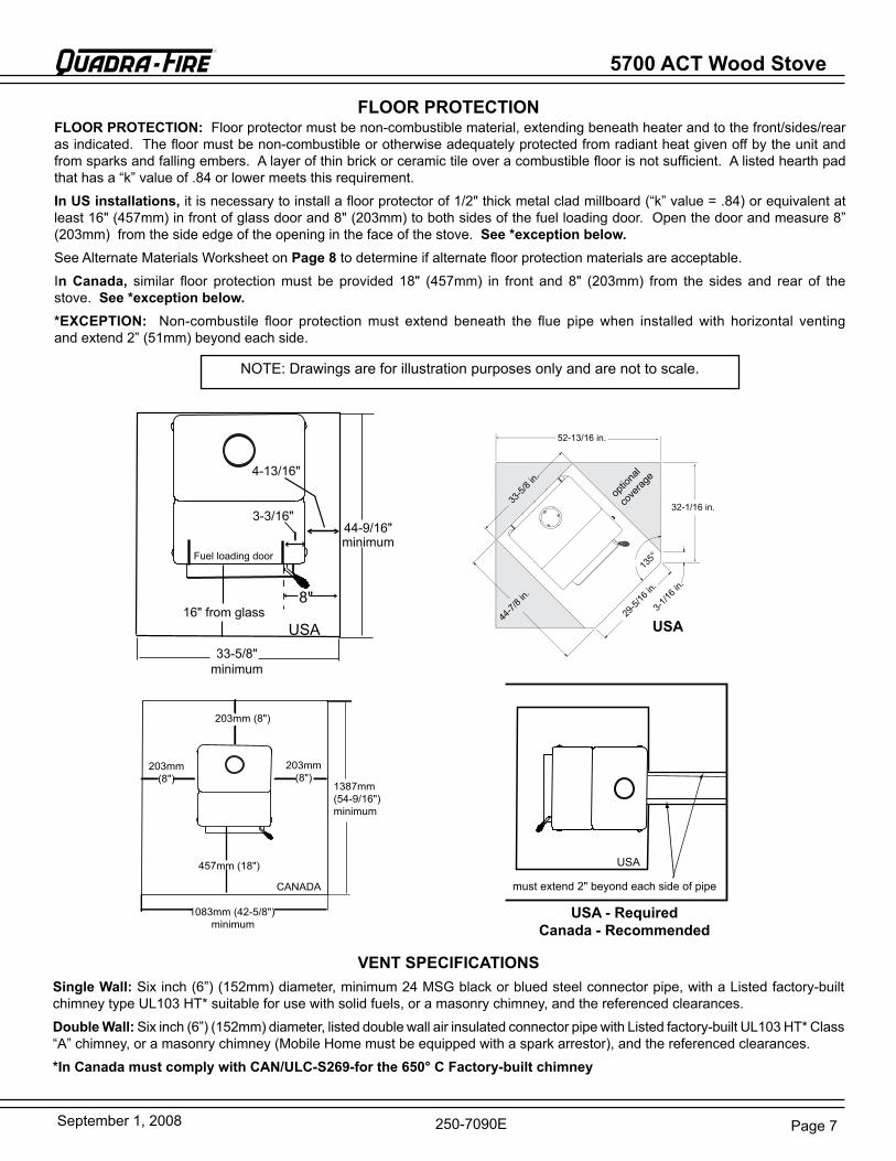
VENT SPECIFICATIONSSingle Wall: Six inch (6”) (152mm) diameter, minimum 24 MSg black or blued steel connector pipe, with a Listed factory-built chimney type UL103 HT* suitable for use with solid fuels, or a masonry chimney, and the referenced clearances.
Double Wall: Six inch (6”) (152mm) diameter, listed double wall air insulated connector pipe with Listed factory-built UL103 HT* Class “A” chimney, or a masonry chimney (Mobile Home must be equipped with a spark arrestor), and the referenced clearances.
*In Canada must comply with CAN/ULC-S269-for the 650° C Factory-built chimney
FLOOR PROTECTION: Floor protector must be non-combustible material, extending beneath heater and to the front/sides/rear as indicated. The floor must be non-combustible or otherwise adequately protected from radiant heat given off by the unit and from sparks and falling embers. A layer of thin brick or ceramic tile over a combustible floor is not sufficient. A listed hearth pad that has a “k” value of .84 or lower meets this requirement.
In US installations, it is necessary to install a floor protector of 1/2" thick metal clad millboard (“k” value = .84) or equivalent at least 16" (457mm) in front of glass door and 8" (203mm) to both sides of the fuel loading door. Open the door and measure 8” (203mm) from the side edge of the opening in the face of the stove. See *exception below. See Alternate Materials Worksheet on Page 8 to determine if alternate floor protection materials are acceptable.
In Canada, similar floor protection must be provided 18" (457mm) in front and 8" (203mm) from the sides and rear of the stove. See *exception below.*EXCEPTION: Non-combustile floor protection must extend beneath the flue pipe when installed with horizontal venting and extend 2” (51mm) beyond each side.
NOTe: Drawings are for illustration purposes only and are not to scale.
USA - RequiredCanada - Recommended
USA
5700 ACT Wood Stove
Page 8 September 1, 2008
R
250-7090e
r = x T1k
r = x T1
K x 12k-factor is given with a required thickness (T) in inches:
K-factor is given with a required thickness (T) in inches:
r-factor is given with a required thickness (T) in inches: r = r x T
r-value given - no conversion needed.
FLOOR PROTECTION (Cont’d)
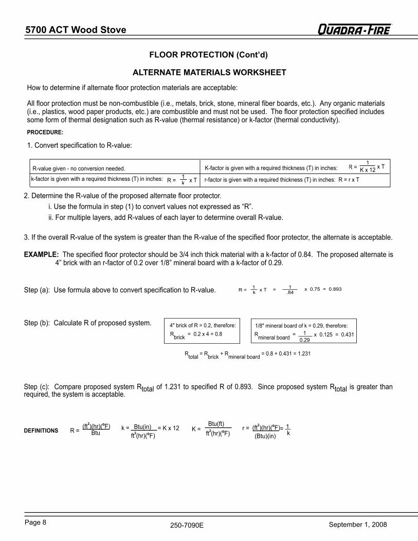
How to determine if alternate floor protection materials are acceptable:
All floor protection must be non-combustible (i.e., metals, brick, stone, mineral fiber boards, etc.). Any organic materials (i.e., plastics, wood paper products, etc.) are combustible and must not be used. The floor protection specified includes some form of thermal designation such as r-value (thermal resistance) or k-factor (thermal conductivity).PROCEDURE:
1. Convert specification to r-value:
2. Determine the r-value of the proposed alternate floor protector. i. Use the formula in step (1) to convert values not expressed as “r”. ii. For multiple layers, add r-values of each layer to determine overall r-value.
3. If the overall r-value of the system is greater than the r-value of the specified floor protector, the alternate is acceptable.
EXAMPLE:The specified floor protector should be 3/4 inch thick material with a k-factor of 0.84. The proposed alternate is 4” brick with an r-factor of 0.2 over 1/8” mineral board with a k-factor of 0.29.
Step (b): Calculate r of proposed system.
= 1r = x T1 x 0.75 = 0.893k .84
rbrick = 0.2 x 4 = 0.84" brick of r = 0.2, therefore: 1/8" mineral board of k = 0.29, therefore:
rmineral board = 10.29
x 0.125 = 0.431
rtotal= rbrick + rmineral board = 0.8 + 0.431 = 1.231
Step (c): Compare proposed system rtotal of 1.231 to specified r of 0.893. Since proposed system rtotal isgreater thanrequired, the system is acceptable.
DEFINITIONS(ft2)(hr)(oF)
btur = btu(in)ft2(hr)(oF)
= K x 12k = 1k
r = (ft2)(hr)(oF)(btu)(in)
=K =btu(ft)
ft2(hr)(oF)
ALTERNATE MATERIALS WORkSHEET
Step (a): Use formula above to convert specification to r-value.
Page 9September 1, 2008
5700 ACT Wood Stove R
250-7090e
To be sure that your Quadra-Fire stove burns properly, the chimney draft (static pressure) should be approximately -.10” water column (W.C.) during a high burn and -.04” W.C. during a low burn, measured 6” (152mm) above the top of the stove after one hour of operation at each burn setting.
NOTE: These are guidelines only, and may vary somewhat for individual installations.
Your Quadra-Fire stove was designed for and tested on a 6” (152mm) chimney, 12’-14’ (360-420cm) high, (includes stove height) measured from the base of the stove. The further your stack height or diameter varies from this configuration, the possibility of performance problems exists. In addition, exterior conditions such as roof line, surrounding trees, prevailing winds and nearby hills can influence stove performance. Your local dealer is the expert in your geographic area and can usually make suggestions or discover solutions that will easily correct your flue problem, allowing your woodstove and its flue system to operate correctly and provide safe and economical heat for your home.
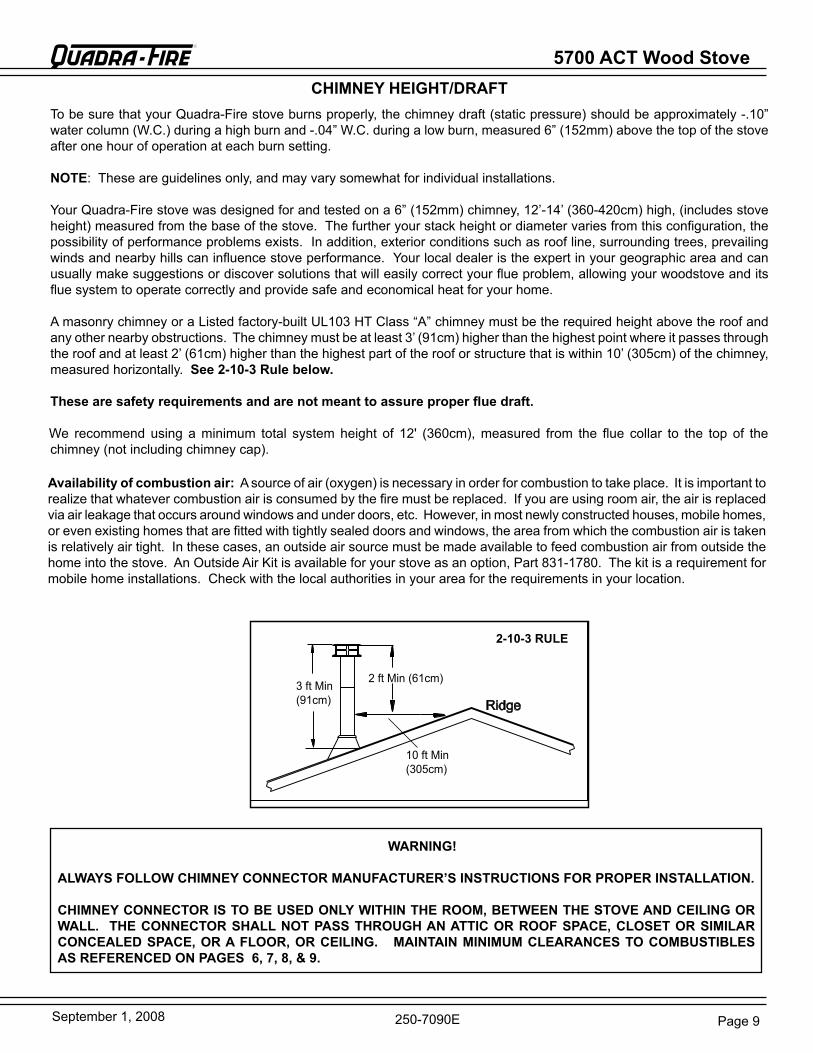
A masonry chimney or a Listed factory-built UL103 HT Class “A” chimney must be the required height above the roof and any other nearby obstructions. The chimney must be at least 3’ (91cm) higher than the highest point where it passes through the roof and at least 2’ (61cm) higher than the highest part of the roof or structure that is within 10’ (305cm) of the chimney, measured horizontally. See 2-10-3 Rule below.
These are safety requirements and are not meant to assure proper flue draft.
We recommend using a minimum total system height of 12' (360cm), measured from the flue collar to the top of the chimney (not including chimney cap).
3 ft Min (91cm)
2 ft Min (61cm)
10 ft Min (305cm)
2-10-3 RULE
WARNING!
ALWAYS FOLLOW CHIMNEY CONNECTOR MANUFACTURER’S INSTRUCTIONS FOR PROPER INSTALLATION.
CHIMNEY CONNECTOR IS TO BE USED ONLY WITHIN THE ROOM, BETWEEN THE STOVE AND CEILING OR WALL. THE CONNECTOR SHALL NOT PASS THROUGH AN ATTIC OR ROOF SPACE, CLOSET OR SIMILAR CONCEALED SPACE, OR A FLOOR, OR CEILING. MAINTAIN MINIMUM CLEARANCES TO COMBUSTIBLES AS REFERENCED ON PAGES 6, 7, 8, & 9.
CHIMNEY HEIGHT/DRAFT
Availability of combustion air: A source of air (oxygen) is necessary in order for combustion to take place. It is important to realize that whatever combustion air is consumed by the fire must be replaced. If you are using room air, the air is replaced via air leakage that occurs around windows and under doors, etc. However, in most newly constructed houses, mobile homes, or even existing homes that are fitted with tightly sealed doors and windows, the area from which the combustion air is taken is relatively air tight. In these cases, an outside air source must be made available to feed combustion air from outside the home into the stove. An Outside Air Kit is available for your stove as an option, Part 831-1780. The kit is a requirement for mobile home installations. Check with the local authorities in your area for the requirements in your location.
5700 ACT Wood Stove
Page 10 September 1, 2008
R
250-7090e
FIGURE 6
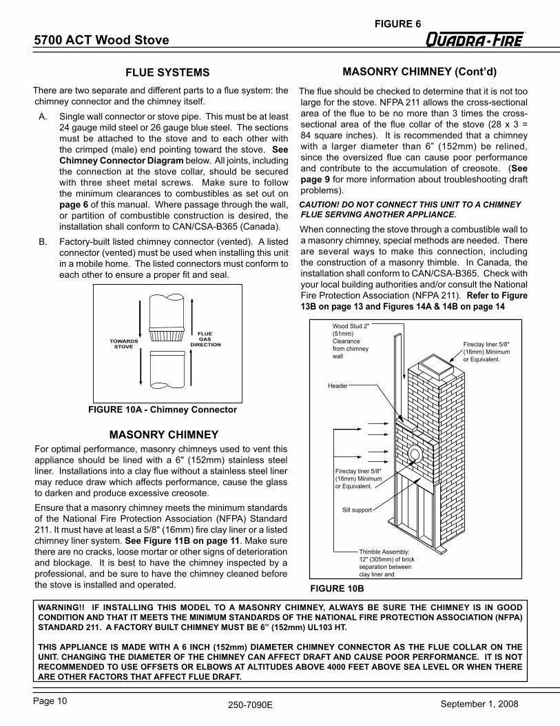
There are two separate and different parts to a flue system: the chimney connector and the chimney itself.A. Single wall connector or stove pipe. This must be at least
24 gauge mild steel or 26 gauge blue steel. The sections must be attached to the stove and to each other with the crimped (male) end pointing toward the stove. See Chimney Connector Diagram below. All joints, including the connection at the stove collar, should be securedwith three sheet metal screws. Make sure to follow the minimum clearances to combustibles as set out on page 6 of this manual. Where passage through the wall, or partition of combustible construction is desired, the installation shall conform to CAN/CSA-b365 (Canada).
b. Factory-built listed chimney connector (vented). A listed connector (vented) must be used when installing this unit in a mobile home. The listed connectors must conform to each other to ensure a proper fit and seal.
FLUE GAS
DIRECTIONTOWARDS
STOVE
FLUE SYSTEMS
WARNING!! IF INSTALLING THIS MODEL TO A MASONRY CHIMNEY, ALWAYS BE SURE THE CHIMNEY IS IN GOOD CONDITION AND THAT IT MEETS THE MINIMUM STANDARDS OF THE NATIONAL FIRE PROTECTION ASSOCIATION (NFPA) STANDARD 211. A FACTORY BUILT CHIMNEY MUST BE 6” (152mm) UL103 HT.
THIS APPLIANCE IS MADE WITH A 6 INCH (152mm) DIAMETER CHIMNEY CONNECTOR AS THE FLUE COLLAR ON THE UNIT. CHANGING THE DIAMETER OF THE CHIMNEY CAN AFFECT DRAFT AND CAUSE POOR PERFORMANCE. IT IS NOT RECOMMENDED TO USE OFFSETS OR ELBOWS AT ALTITUDES ABOVE 4000 FEET ABOVE SEA LEVEL OR WHEN THERE ARE OTHER FACTORS THAT AFFECT FLUE DRAFT.
FIGURE 10A - Chimney Connector
Thimble Assembly:12" (305mm) of brick separation between claylinerandcombustibles.
Fireclay liner 5/8" (16mm) Minimum or equivalent.
Sill support
Header
Wood Stud 2" (51mm)Clearance from chimney wall
Fireclay liner 5/8" (16mm) Minimum or equivalent.
The flue should be checked to determine that it is not too large for the stove. NFPA 211 allows the cross-sectional area of the flue to be no more than 3 times the cross-sectional area of the flue collar of the stove (28 x 3 = 84 square inches). It is recommended that a chimney with a larger diameter than 6” (152mm) be relined, since the oversized flue can cause poor performance and contribute to the accumulation of creosote. (See page 9 for more information about troubleshooting draft problems). CAUTION! DO NOT CONNECT THIS UNIT TO A CHIMNEY FLUE SERVING ANOTHER APPLIANCE.
When connecting the stove through a combustible wall to a masonry chimney, special methods are needed. There are several ways to make this connection, including the construction of a masonry thimble. In Canada, the installation shall conform to CAN/CSA-b365. Check with your local building authorities and/or consult the National Fire Protection Association (NFPA 211). Refer to Figure 13B on page 13 and Figures 14A & 14B on page 14
MASONRY CHIMNEY
FIGURE 10B
ensure that a masonry chimney meets the minimum standards of the National Fire Protection Association (NFPA) Standard 211. It must have at least a 5/8" (16mm) fire clay liner or a listed chimney liner system. See Figure 11B on page 11. Make sure there are no cracks, loose mortar or other signs of deterioration and blockage. It is best to have the chimney inspected by a professional, and be sure to have the chimney cleaned before the stove is installed and operated.
MASONRY CHIMNEY (Cont’d)
For optimal performance, masonry chimneys used to vent this appliance should be lined with a 6" (152mm) stainless steel liner. Installations into a clay flue without a stainless steel liner may reduce draw which affects performance, cause the glass to darken and produce excessive creosote.
Page 11September 1, 2008
5700 ACT Wood Stove R
250-7090e
FLOOr PrOTeCTOr
THIMbLe,12" (305mm) OF brICK
CeILINg JOIST
COMbUSTIbLe WALL
1" (25mm) CLeArANCe
AIrTIgHTCLeANOUT DOOr
FIreCLAY FLUe LINer WITH AIr SPACe
SHeATHINg
eAVe
1" (25mm) CLeArANCe WITH FIreSTOP
rAFTer
FLASHINg
CONCreTe CAP
FIGURE 11B
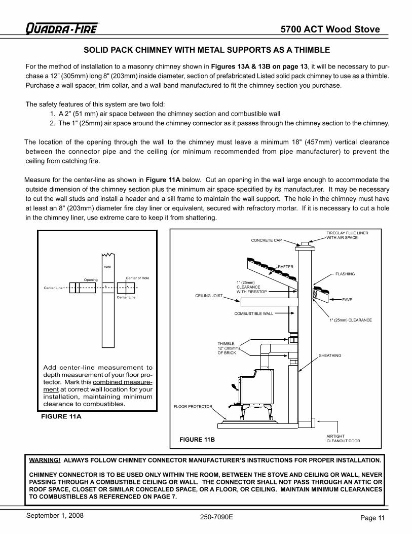
SOLID PACk CHIMNEY WITH METAL SUPPORTS AS A THIMBLE
For the method of installation to a masonry chimney shown in Figures 13A & 13B on page 13, it will be necessary to pur-chase a 12” (305mm) long 8" (203mm) inside diameter, section of prefabricated Listed solid pack chimney to use as a thimble. Purchase a wall spacer, trim collar, and a wall band manufactured to fit the chimney section you purchase.
The safety features of this system are two fold: 1. A 2" (51 mm) air space between the chimney section and combustible wall 2. The 1" (25mm) air space around the chimney connector as it passes through the chimney section to the chimney.
The location of the opening through the wall to the chimney must leave a minimum 18" (457mm) vertical clearance between the connector pipe and the ceiling (or minimum recommended from pipe manufacturer) to prevent the ceiling from catching fire.
Measure for the center-line as shown in Figure 11A below. Cut an opening in the wall large enough to accommodate the outside dimension of the chimney section plus the minimum air space specified by its manufacturer. It may be necessary to cut the wall studs and install a header and a sill frame to maintain the wall support. The hole in the chimney must have at least an 8" (203mm) diameter fire clay liner or equivalent, secured with refractory mortar. If it is necessary to cut a hole in the chimney liner, use extreme care to keep it from shattering.
WARNING! ALWAYS FOLLOW CHIMNEY CONNECTOR MANUFACTURER’S INSTRUCTIONS FOR PROPER INSTALLATION.
CHIMNEY CONNECTOR IS TO BE USED ONLY WITHIN THE ROOM, BETWEEN THE STOVE AND CEILING OR WALL, NEVER PASSING THROUGH A COMBUSTIBLE CEILING OR WALL. THE CONNECTOR SHALL NOT PASS THROUGH AN ATTIC OR ROOF SPACE, CLOSET OR SIMILAR CONCEALED SPACE, OR A FLOOR, OR CEILING. MAINTAIN MINIMUM CLEARANCES TO COMBUSTIBLES AS REFERENCED ON PAGE 7.
Add center-line measurement to depth measurement of your floor pro-tector. Mark this combined measure-ment at correct wall location for your installation, maintaining minimum clearance to combustibles.
Center of Hole
Wall
Center Line
Opening
Center Line
FIGURE 11A
5700 ACT Wood Stove
Page 12 September 1, 2008
R
250-7090e
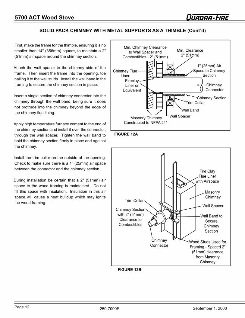
First, make the frame for the thimble, ensuring it is no smaller than 14" (356mm) square, to maintain a 2" (51mm) air space around the chimney section.Attach the wall spacer to the chimney side of the frame. Then insert the frame into the opening, toe nailing it to the wall studs. Install the wall band in the framing to secure the chimney section in place.
Insert a single section of chimney connector into the chimney through the wall band, being sure it does not protrude into the chimney beyond the edge of the chimney flue lining.
Apply high temperature furnace cement to the end of the chimney section and install it over the connector, through the wall spacer. Tighten the wall band to hold the chimney section firmly in place and against the chimney.
Install the trim collar on the outside of the opening. Check to make sure there is a 1" (25mm) air space between the connector and the chimney section.
During installation be certain that a 2" (51mm) air space to the wood framing is maintained. Do not fill this space with insulation. Insulation in this air space will cause a heat buildup which may ignite the wood framing.
Chimney Flue Liner
Fireclay Liner or
equivalent
Masonry Chimney Constructed to NFPA211
Wall SpacerWall band
Trim Collar
Chimney Connector
1" (25mm) Air Space to Chimney
Section
Min. Clearance 2" (51mm)
Min. Chimney Clearance toWall Spacer and
Combustibles - 2" (51mm)
Chimney Section
Trim Collar
Chimney Section with 2" (51mm)Clearance to Combustibles
Chimney Connector
Fire Clay Flue Liner
with Airspace
Masonry Chimney
Wall band to Secure
Chimney Section
Wood Studs Used for Framing - Spaced 2" (51mm) clearance
from Masonry Chimney
Wall Spacer
FIGURE 12B
FIGURE 12A
SOLID PACk CHIMNEY WITH METAL SUPPORTS AS A THIMBLE (Cont’d)
Page 13September 1, 2008
5700 ACT Wood Stove R
250-7090e
IMPORTANT!Follow the manufacturer’s
installation instructions and maintain the
manufacturer’s specified clearance distances.
*
FloorProtector
Chimney Connector
CombustibleCeiling
Combustible Wall
Insulated " T "
Flashing
Listed CapMaintain 2" (51mm)Clearance Through eave
*
Listed Chimney PipeChimney Connector
To Stove
Trim Collar on Inside
Wall
Combustible Outside Wall
2" (51mm)Clearance
Listed Chimney
Insulated " T "
Wall Support
Wall Spacer on Outside Wall
*refer to Clearances to Combustibles
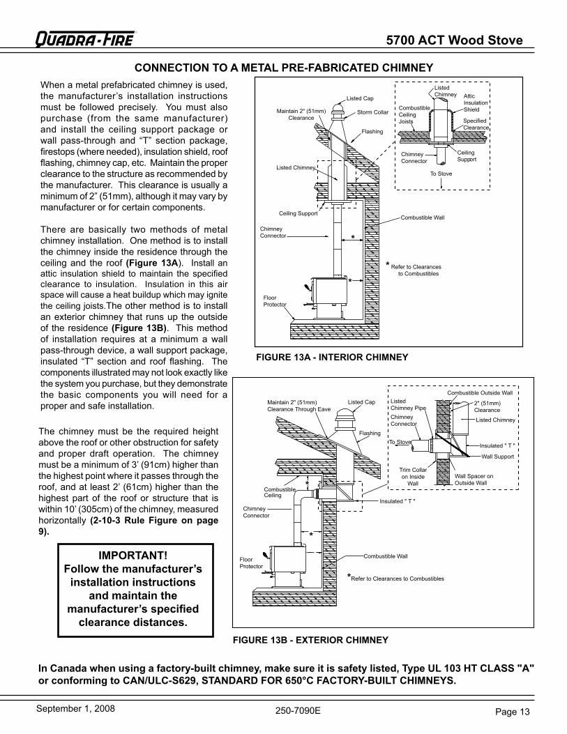
CONNECTION TO A METAL PRE-FABRICATED CHIMNEYWhen a metal prefabricated chimney is used, the manufacturer’s installation instructions must be followed precisely. You must also purchase (from the same manufacturer) and install the ceiling support package or wall pass-through and “T” section package, firestops (where needed), insulation shield, roof flashing, chimney cap, etc. Maintain the proper clearance to the structure as recommended by the manufacturer. This clearance is usually a minimum of 2” (51mm), although it may vary by manufacturer or for certain components.
There are basically two methods of metal chimney installation. One method is to install the chimney inside the residence through the ceiling and the roof (Figure 13A). Installanattic insulation shield to maintain the specified clearance to insulation. Insulation in this air space will cause a heat buildup which may ignite the ceiling joists.The other method is to install an exterior chimney that runs up the outside of the residence (Figure 13B). This method of installation requires at a minimum a wall pass-through device, a wall support package, insulated “T” section and roof flashing. The components illustrated may not look exactly like the system you purchase, but they demonstrate the basic components you will need for a proper and safe installation.
Combustible Wall
Floor Protector
Chimney Connector
Ceiling Support
Listed Chimney
Maintain 2" (51mm)Clearance
Listed Cap
Storm Collar
Flashing
*
** refer to Clearances to Combustibles
Combustible Ceiling Joists
Chimney Connector
To Stove
Ceiling Support
Specified Clearance
Attic Insulation Shield
Listed Chimney
FIGURE 13A - INTERIOR CHIMNEY
The chimney must be the required height above the roof or other obstruction for safety and proper draft operation. The chimney must be a minimum of 3’ (91cm) higher than the highest point where it passes through the roof, and at least 2’ (61cm) higher than the highest part of the roof or structure that is within 10’ (305cm) of the chimney, measured horizontally (2-10-3 Rule Figure on page 9).
FIGURE 13B - EXTERIOR CHIMNEY
In Canada when using a factory-built chimney, make sure it is safety listed, Type UL 103 HT CLASS "A" or conforming to CAN/ULC-S629, STANDARD FOR 650°C FACTORY-BUILT CHIMNEYS.
5700 ACT Wood Stove
Page 14 September 1, 2008
R
250-7090e
Spark Arestor Cap
roof Flashing
Storm Collar
Joist Shield/FirestopDoubleWallConnector Pipe
Outside Air Kit Connector
Floor Protector
Outside Air Floor Vent
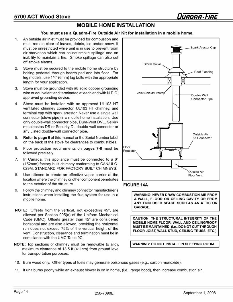
1. An outside air inlet must be provided for combustion and must remain clear of leaves, debris, ice and/or snow. It must be unrestricted while unit is in use to prevent room air starvation which can cause smoke spillage and an inability to maintain a fire. Smoke spillage can also set off smoke alarms.
2. Stove must be secured to the mobile home structure by bolting pedestal through hearth pad and into floor. For leg models, use 1/4” (6mm) lag bolts with the appropriate length for your application.
3. Stove must be grounded with #8 solid copper grounding wire or equivalent and terminated at each end with N.e.C. approved grounding device.
4. Stove must be installed with an approved UL103 HT ventilated chimney connector, UL103 HT chimney, and terminal cap with spark arrestor. Never use a single wall connector (stove pipe) in a mobile home installation. Use only double-wall connector pipe, Dura-Vent DVL, Selkirk metalbestos DS or Security DL double-wall connector or any Listed double-wall connector pipe.
5. Refer to page 6 of this manual or the Serial Number label on the back of the stove for clearances to combustibles.
6. Floor protection requirements on pages 7-8 must be followed precisely.
7. In Canada, this appliance must be connected to a 6” (152mm) factory-built chimney conforming to CAN/ULC-629M, STANDArD FOr FACTOrY bUILT CHIMNeYS.
8. Use silicone to create an effective vapor barrier at the location where the chimney or other component penetrates to the exterior of the structure.
9. Follow the chimney and chimney connector manufacturer’s instructions when installing the flue system for use in a mobile home.
NOTE: Offsets from the vertical, not exceeding 45°, are allowed per Section 905(a) of the Uniform Mechanical Code (UMC). Offsets greater than 45° are considered horizontal and are also allowed, providing the horizontal run does not exceed 75% of the vertical height of the vent. Construction, clearance and termination must be in compliance with the UMC Table 9C.
MOBILE HOME INSTALLATION
WARNING: NEVER DRAW COMBUSTION AIR FROM A WALL, FLOOR OR CEILING CAVITY OR FROM ANY ENCLOSED SPACE SUCH AS AN ATTIC OR GARAGE.
CAUTION: THE STRUCTURAL INTEGRITY OF THE MOBILE HOME FLOOR, WALL AND CEILING/ROOF MUST BE MAINTAINED. (i.e., DO NOT CUT THROUGH FLOOR JOIST, WALL STUD, CEILING TRUSS, ETC.)
WARNING: DO NOT INSTALL IN SLEEPING ROOM.
You must use a Quadra-Fire Outside Air kit for installation in a mobile home.
10. burn wood only. Other types of fuels may generate poisonous gases (e.g., carbon monoxide).
11. If unit burns poorly while an exhaust blower is on in home, (i.e., range hood), then increase combustion air.
FIGURE 14A
NOTE: Top sections of chimney must be removable to allow maximum clearance of 13.5 ft (411cm) from ground level for transportation purposes.
Page 15September 1, 2008
5700 ACT Wood Stove R
250-7090e
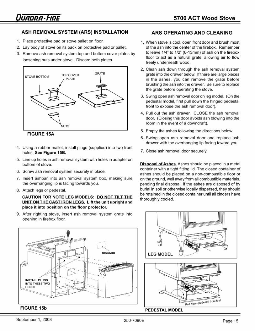
1. Place protective pad or stove pallet on floor.2. Lay body of stove on its back on protective pad or pallet.3. remove ash removal system top and bottom cover plates by
loosening nuts under stove. Discardbothplates.
ASH REMOVAL SYSTEM (ARS) INSTALLATION
1. When stove is cool, open front door and brush most of the ash into the center of the firebox. remember to leave 1/4” to 1/2” (6-13mm) of ash on the firebox floor to act as a natural grate, allowing air to flow freely underneath wood.
2. Clean ash down through the ash removal system grate into the drawer below. If there are large pieces in the ashes, you can remove the grate before brushing the ash into the drawer. be sure to replace the grate before operating the stove.
3. Swing open ash removal door on leg model. (On the pedestal model, first pull down the hinged pedestal front to expose the ash removal door).
4. Pull out the ash drawer. CLOSe the ash removal door. (Closing this door avoids ash blowing into the room in the event of a downdraft).
5. empty the ashes following the directions below.6. Swing open ash removal door and replace ash
drawer with the overhanging lip facing toward you.
7. Close ash removal door securely.
ARS OPERATING AND CLEANING
FIGURE 15b
4. Using a rubber mallet, install plugs (supplied) into two front holes,See Figure 15B.
5. Line up holes in ash removal system with holes in adapter on bottom of stove.
6. Screw ash removal system securely in place.7. Insert ashpan into ash removal system box, making sure
the overhanging lip is facing towards you.8. Attach legs or pedestal.
CAUTION FOR NOTE LEG MODELS: DO NOT TILT THE UNIT ON THE CAST IRON LEGS.Lift the unit upright and place it into position on the floor protector.
9. After righting stove, insert ash removal system grate into opening in firebox floor.
PEDESTAL MODEL
DISCARD
INSTALL PLUGS INTO THESE TWO HOLES Ash Drawer
Pull down pedestal front first
Disposal of Ashes. Ashes should be placed in a metal container with a tight fitting lid. The closed container of ashes should be placed on a non-combustible floor or on the ground, well away from all combustible materials, pending final disposal. If the ashes are disposed of by burial in soil or otherwise locally dispersed, they should beretainedintheclosedcontaineruntilallcindershavethoroughly cooled.
Ash Drawer
LEG MODEL
STOVe bOTTOM
NUTS
TOP COVer PLATe
grATe
FIGURE 15A

5700 ACT Wood Stove
Page 16 September 1, 2008
R
250-7090e
PEDESTAL MODEL
1 Place protective pad or stove pallet on floor.2. Lay body of stove on its back on protective pad or
pallet.3. Loosen screws on adapter and slide pedestal over
adapter on bottom of stove4. Line up holes in sides of pedestal with holes in
adapter.5. Securely tighten pedestal into place.6. Carefully stand stove up and place in desired loca-
tion.7. Slip wooden decorative strips onto pedestal edges.8. Open door of stove and check to make sure firebricks
and ceramic blanket are in their proper locations (see pages 23-24).
PEDESTAL OR LEG kIT INSTALLATION
LEG MODEL
1. remove leg mounting brackets packaged inside fire-box.
2. Place protective pad or stove pallet on floor.3. Lay body of stove on its back on protective pad or
pallet.4 remove the bolts, using a 9/16” Hex Head socket or
wrench, from the adapter and save.5. Secure mounting brackets to the bottom of the stove
with 1/4”-20 Phillips screws. See Figure 16A. These screws are located on the outer skin at the bottom rear of the stove.
6. Loosely assembly bolts into the corner of the mounting brackets.
7. Slide legs onto mounting brackets and tighten.
8. Carefully stand stove up and place in desired location.
9. Use leveling bolts on legs to stabilize and level stove.
10. Open door of stove and check to make sure firebricks and ceramic blanket are in their proper locations (see pages 23-24).
Leg MOUNTINg brACKeTS (packaged inside stove firebox).
CAUTION! DO NOT TILT THE UNIT ON THE CAST IRON LEGS. Lift the unit upright and place it into position on the floor protector.
FIGURE 16A
FIGURE 16B
WARNING: DO NOT OPERATE STOVE BEFORE FULLY ASSEMBLING ALL COMPONENTS. BURNING YOUR STOVE WITHOUT A PEDESTAL OR LEG kIT ATTACHED WILL VOID YOUR WARRANTY AND COULD PRESENT A SAFETY HAZARD.
Page 17September 1, 2008
5700 ACT Wood Stove R
250-7090e
bLOWer SPeeD CONTrOL
blower Mounting Flange
Outer Skin
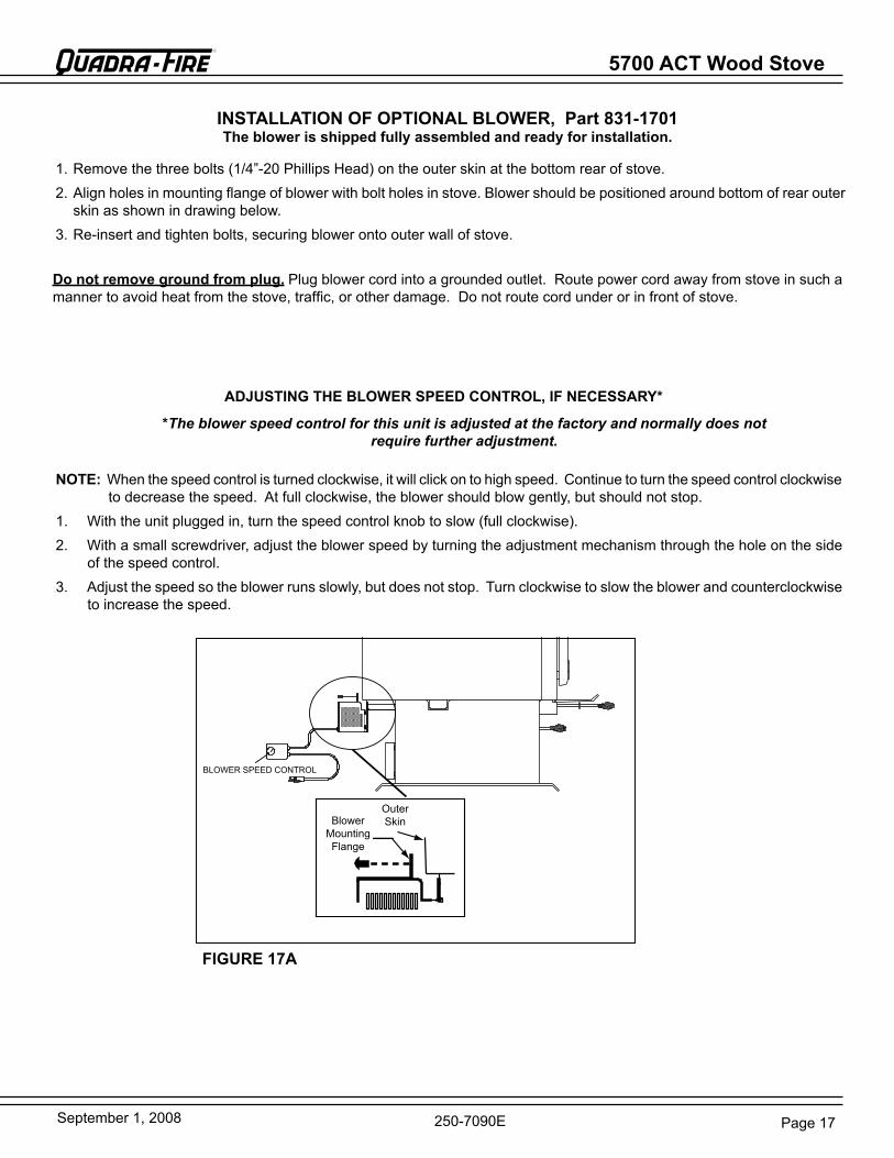
INSTALLATION OF OPTIONAL BLOWER, Part 831-1701The blower is shipped fully assembled and ready for installation.
NOTE: When the speed control is turned clockwise, it will click on to high speed. Continue to turn the speed control clockwise to decrease the speed. At full clockwise, the blower should blow gently, but should not stop.
1. With the unit plugged in, turn the speed control knob to slow (full clockwise).2. With a small screwdriver, adjust the blower speed by turning the adjustment mechanism through the hole on the side
of the speed control.3. Adjust the speed so the blower runs slowly, but does not stop. Turn clockwise to slow the blower and counterclockwise
to increase the speed.
*The blower speed control for this unit is adjusted at the factory and normally does not require further adjustment.
1. remove the three bolts (1/4”-20 Phillips Head) on the outer skin at the bottom rear of stove.2. Align holes in mounting flange of blower with bolt holes in stove. blower should be positioned around bottom of rear outer
skin as shown in drawing below.3. re-insert and tighten bolts, securing blower onto outer wall of stove.
Do not remove ground from plug.Plug blower cord into a grounded outlet. route power cord away from stove in such a manner to avoid heat from the stove, traffic, or other damage. Do not route cord under or in front of stove.
ADJUSTING THE BLOWER SPEED CONTROL, IF NECESSARY*
FIGURE 17A
5700 ACT Wood Stove
Page 18 September 1, 2008
R
250-7090e
Front Cover
Side Cover (2)
4 in. Flex Line (Not Included)
Outside Air Termination Cap(contains rodent screen)
Flex Flange
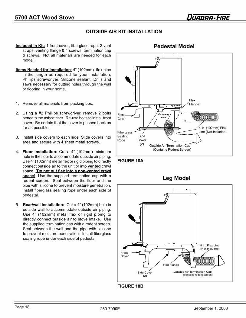
OUTSIDE AIR kIT INSTALLATION
Front Cover
Side Cover
(2)
4 in. (102mm) Flex Line (Not Included)
Flex Flange
Outside Air Termination Cap(Contains rodent Screen)
Fiberglass Sealing rope
Cut-away view
Pedestal Model
Leg Model
Included in kit: 1 front cover; fiberglass rope; 2 vent straps; venting flange & 4 screws; termination cap & screws. Not all materials are needed for each model.
Items Needed for Installation: 4” (102mm) flex pipe in the length as required for your installation; Phillips screwdriver; Silicone sealant; Drills and saws necessary for cutting holes through the wall or flooring in your home.
1. remove all materials from packing box.
2. Using a #2 Phillips screwdriver, remove 2 bolts beneath the ashcatcher. re-use bolts to install front cover. be certain that the cover is pushed back as far as possible.
3. Install side covers to each side. Slide covers into area and secure with 4 sheet metal screws.
4. Floor installation: Cut a 4” (102mm) minimum hole in the floor to accommodate outside air piping. Use 4” (102mm) metal flex or rigid piping to directly connectoutsideairtotheunitorintovented crawl space. (Do not put flex into a non-vented crawl space). Use the supplied termination cap with a rodent screen. Seal between the floor and the pipe with silicone to prevent moisture penetration. Install fiberglass sealing rope under each side of pedestal.
5. Rear/wall installation: Cut a 4” (102mm) hole in outside wall to accommodate outside air piping. Use 4” (102mm) metal flex or rigid piping to directly connect outside air to stove intake. Use the supplied termination cap with a rodent screen. Seal between the wall and the pipe with silicone to prevent moisture penetration. Install fiberglass sealing rope under each side of pedestal.
FIGURE 18B
FIGURE 18A
Page 19September 1, 2008
5700 ACT Wood Stove R
250-7090e
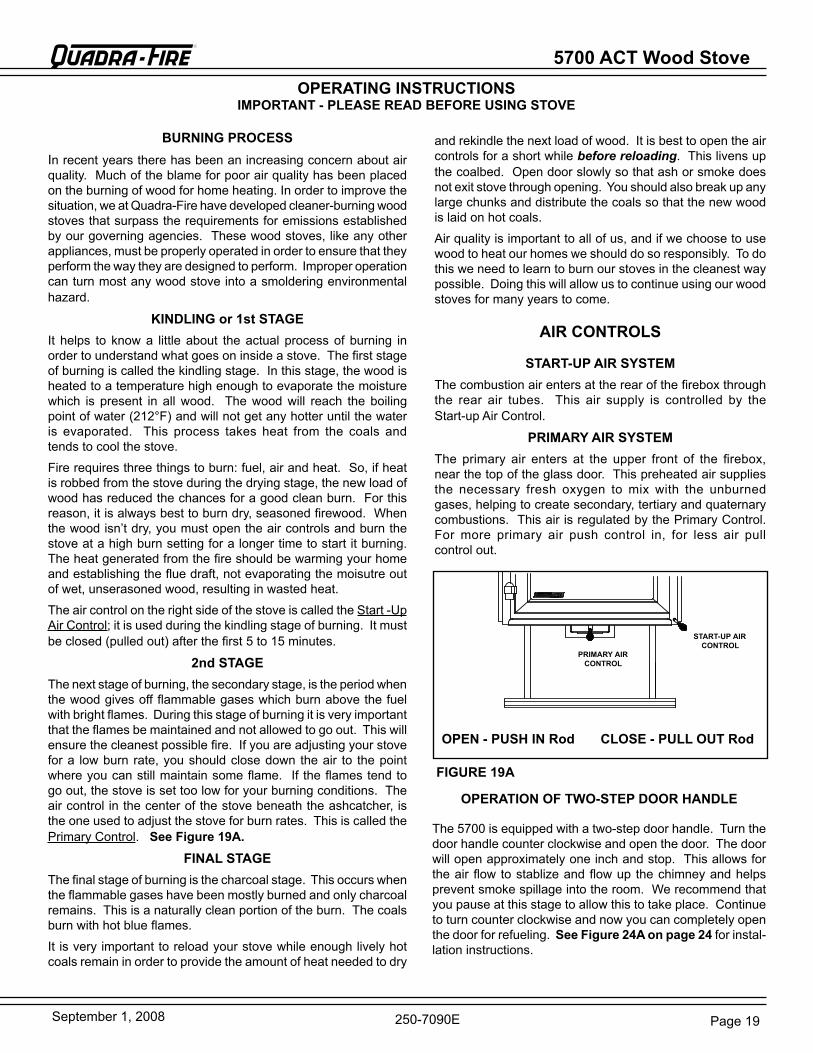
START-UP AIRCONTROL
PRIMARY AIRCONTROL
BURNING PROCESSInrecentyearstherehasbeenanincreasingconcernaboutairquality. Much of the blame for poor air quality has been placed on the burning of wood for home heating. In order to improve the situation, we at Quadra-Fire have developed cleaner-burning wood stoves that surpass the requirements for emissions established by our governing agencies. These wood stoves, like any other appliances, must be properly operated in order to ensure that they perform the way they are designed to perform. Improper operation can turn most any wood stove into a smoldering environmental hazard.
kINDLING or 1st STAGEIt helps to know a little about the actual process of burning in order to understand what goes on inside a stove. The first stage of burning is called the kindling stage. In this stage, the wood is heated to a temperature high enough to evaporate the moisture which is present in all wood. The wood will reach the boiling point of water (212°F) and will not get any hotter until the water is evaporated. This process takes heat from the coals and tends to cool the stove.
Fire requires three things to burn: fuel, air and heat. So, if heat is robbed from the stove during the drying stage, the new load of wood has reduced the chances for a good clean burn. For this reason, it is always best to burn dry, seasoned firewood. When the wood isn’t dry, you must open the air controls and burn the stove at a high burn setting for a longer time to start it burning. The heat generated from the fire should be warming your home and establishing the flue draft, not evaporating the moisutre out of wet, unserasoned wood, resulting in wasted heat.
The air control on the right side of the stove is called the Start -Up Air Control; it is used during the kindling stage of burning. It must be closed (pulled out) after the first5 to 15 minutes.
2nd STAGEThe next stage of burning, the secondary stage, is the period when the wood gives off flammable gases which burn above the fuel with bright flames. During this stage of burning it is very important that the flames be maintained and not allowed to go out. This will ensure the cleanest possible fire. If you are adjusting your stove for a low burn rate, you should close down the air to the point where you can still maintain some flame. If the flames tend to go out, the stove is set too low for your burning conditions. The air control in the center of the stove beneath the ashcatcher, is the one used to adjust the stove for burn rates. This is called the Primary Control. See Figure 19A.
FINAL STAGEThe final stage of burning is the charcoal stage. This occurs when the flammable gases have been mostly burned and only charcoal remains. This is a naturally clean portion of the burn. The coals burn with hot blue flames.
It is very important to reload your stove while enough lively hot coals remain in order to provide the amount of heat needed to dry
and rekindle the next load of wood. It is best to open the air controls for a short while before reloading. This livens up thecoalbed. Open door slowly so that ash or smoke does not exit stove through opening. You should also break up any large chunks and distribute the coals so that the new wood is laid on hot coals.
Air quality is important to all of us, and if we choose to use wood to heat our homes we should do so responsibly. To do this we need to learn to burn our stoves in the cleanest way possible. Doing this will allow us to continue using our wood stoves for many years to come.
OPERATING INSTRUCTIONSIMPORTANT - PLEASE READ BEFORE USING STOVE
START-UP AIR SYSTEMThe combustion air enters at the rear of the firebox through the rear air tubes. This air supply is controlled by the Start-up Air Control.
PRIMARY AIR SYSTEMThe primary air enters at the upper front of the firebox, near the top of the glass door. This preheated air supplies the necessary fresh oxygen to mix with the unburned gases, helping to create secondary, tertiary and quaternary combustions. This air is regulated by the Primary Control. For more primary air push control in, for less air pull control out.
OPEN - PUSH IN Rod CLOSE - PULL OUT Rod
AIR CONTROLS
FIGURE 19A
OPERATION OF TWO-STEP DOOR HANDLE
The 5700 is equipped with a two-step door handle. Turn the door handle counter clockwise and open the door. The door will open approximately one inch and stop. This allows for the air flow to stablize and flow up the chimney and helps prevent smoke spillage into the room. We recommend that you pause at this stage to allow this to take place. Continue to turn counter clockwise and now you can completely openthe door for refueling. See Figure 24A on page 24 for instal-lation instructions.
5700 ACT Wood Stove
Page 20 September 1, 2008
R
250-7090e
NOTE: These are approximate settings, and will vary with type of wood or chimney draft. Due to altitude and other environmental circumstances, this operation information is a guideline only. Similar burn rates may be obtained using other settings unique to your situation.
There are many ways to build a fire. The basic principle is to light easily-ignitable tinder or paper, which ignites the fast burning kindling, which in turn ignites the slow-burning firewood. Here is one method that works well:1. Place several wads of crushed paper on the firebox floor. Heating the flue with slightly crumpled newspaper before
adding kindling keeps smoke to a minimum.2. Lay small dry sticks of kindling on top of the paper.3. Open Start-Up Air Control and Primary Air Control fully.4. Make sure that no matches or other combustibles are in the immediate area of the stove. be sure the room is adequately
ventilated and the flue unobstructed.5. Light the paper in the stove. NeVer light or rekindle stove with kerosene, gasoline, or charcoal lighter fluid; the
results can be fatal.6. Once the kindling is burning quickly, add several full-length logs 3” (76mm) or 4” (102mm) in diameter. be careful not
to smother the fire. Stack the pieces of wood carefully: near enough to keep each other hot, but far enough away from each other to allow adequate air flow between them.
7. When ready to reload the stove, add more logs. Large logs burn slowly, holding a fire longer. Small logs burn fast and hot, giving quick heat.
8. Adjust the Start-Up Air Control and Primary Control; the more you close down the Primary Control, the lower and slower the fire will burn. The more you open the Primary Control, the more heat will be produced. The Start-Up Air Control is only used for the first 5 to 15 minutes.
As long as there are hot coals, repeating steps 7 and 8 will maintain a continuous fire throughout the season.
NOTE: The special high temperature paint that your stove is finished with will cure as your stove heats. You will notice an odor and perhaps see some vapor rise from the stove surface; this is normal. We recommend that you open a window until the odor dissipates and paint is cured.
NOTE: Stove should be run full open for 15 minutes a day to keep air passages clean.
WARNING! ALWAYS OPERATE THIS APPLIANCE WITH THE DOOR CLOSED AND LATCHED EXCEPT DURING START-UP AND RE-FUELING .
WARNING! DO NOT LEAVE THE FIRE UNATTENDED WHEN THE DOOR IS UNLATCHED. UNSTABLE FIREWOOD COULD FALL OUT OF THE FIREBOX CREATING A FIRE HAZARD TO YOUR HOME.
CAUTION: Before lighting your first fire in the stove: 1) Make certain that the baffle is correctly positioned. It should be resting against the rear support; 2) Follow instructions on page 20 for cleaning plated surfaces, and; 3) Remove all labels from glass front.
BUILDING A FIRE
CAUTION: Never use gasoline, gasoline-type lantern fuel, kerosene, charcoal lighter fluid, or similar liquids to start or “freshen up” a fire in this heater. Keep all such liquids well away from the heater while it is in use.
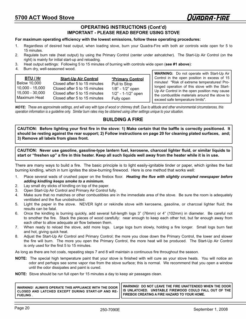
For maximum operating efficiency with the lowest emissions, follow these operating procedures:1. regardless of desired heat output, when loading stove, burn your Quadra-Fire with both air controls wide open for 5 to
15 minutes.2. regulate burn rate (heat output) by using the Primary Control (center under ashcatcher). The Start-Up Air Control (on the
right) is mainly for initial start-up and reloading.3. Heat output settings: Following 5 to 15 minutes of burning with controls wide open (see #1 above):4. burn dry, well-seasoned wood.
OPERATING INSTRUCTIONS (Cont’d)IMPORTANT - PLEASE READ BEFORE USING STOVE
WARNING: Do not operate with Start-Up Air Control in the open position in excess of 15 minutes! "risk of extreme temperatures! Pro-longed operation of this stove with the Start-Up Air Control in the open position may cause the combustible materials around the stove to exceed safe temperature limits".
BTU / Hrbelow 10,00010,000 - 15,00015,000 - 30,000Maximum Heat
Start-Up Air ControlClosed after 5 to 15 minutesClosed after 5 to 15 minutesClosed after 5 to 15 minutesClosed after 5 to 15 minutes
*Primary ControlPull to Stop1/8” - 1/2” open1/2” - 1-1/2” openFully open
Page 21September 1, 2008
5700 ACT Wood Stove R
250-7090e
OPACITYThis is the measure of how cleanly your stove is burning. Opacity is measured in percent; 100% opacity is when an object is totally obscured by the smoke column from a chimney, and 0% opacity means that no smoke column can be seen. As you become familiar with your stove, you should periodically check the opacity. This will allow you to know how to burn your stove as nearly smoke-free as possible (goal of 0% opacity).
BURN RATES• STARTING FIRE: Open (push in) both controls fully. After a wood load has been burning for 5 to 15 minutes (longer for very large pieces) close the Start-Up Air Control by pulling it out (to the right of the stove).
• HIGH: Leave the Primary Air Control fully open (center of stove under the ashcatcher). It is important to do this when reloading the stove. Failure to do this could result in excessive emissions (opacity).
After a wood load has been burning for 5 to 15 minutes on High to achieve the following burn rates set the controls as listed below:• MEDIUM HIGH: Close the Primary Air Control to 1/2” to 1-1/2” (13-38mm) open, Start-Up Air is closed.
• MEDIUM LOW: Close the Primary Control to 1/8” -1/2” (3-13mm) open. Start-Up Air is closed.
• LOW: gradually close down the Primary Control, making sure to maintain flames in the stove. (Star-Up Air is closed.) It is very important to maintain flames in your stove during the first few hours of a low burn to avoid excessive air pollution.
BLOWER OPERATING INSTRUCTIONS(see blower installation instructions on page 17)
If your Quadra-Fire wood stove is equipped with an optional blower, you should follow these guidelines:
1. Initial (cold) start-up: Leave blower off until your stove is hot and a good coalbed is established. The blower may be turned on approximately 15 minutes after loading the stove with fuel.
2. High burn setting: The blower may be left on throughout the burn.
3. Medium or Medium-High burn setting: The blower should be left off until a good burn is established, then turned on at a medium or high rate.
4. Low burn setting: The blower tends to cool off the stove. If you are using wet wood or a very low burn setting, leave blower off until the burn is well established. Then, if you wish, turn the blower on at a lower rate. Too high a blower setting with a low burn rate may adversely affect emissions.
5. The blower is equipped with a speed control. The highest blower speed is obtained by turning the speed control to“ON” and then adjusting counterclockwise towards “OFF” as far as possible without turning the blower off. For a low blower speed, turn the control knob clockwise as far as possible.
OPERATING INSTRUCTIONS (Cont’d)
CAUTION: DO NOT STORE WOOD CLOSER THAN THE REQUIRED CLEARANCES TO COMBUSTIBLE OF THE STOVE OR WITHIN THE SPACE REQUIRED FOR LOADING AND ASH REMOVAL.
WOOD SELECTION AND STORAGE
burn only dry seasoned wood. Store wood under cover, out of the rain and snow. Dry and well-seasoned wood will not only minimize the chance of creosote formation, but will give you the most efficient fire. even dry wood contains at least 15% moisture by weight, and should be burned hot enough to keep the chimney hot for as long as it takes to dry the wood out - about one hour. It is a waste of energy to burn unseasoned wood of any kind.
Dead wood lying on the forest floor should be considered wet, and requires full seasoning time. Standing dead wood can be considered to be about two-thirds seasoned. To tell if wood is dry enough to burn, check the ends of the logs. If there are cracks radiating in all directions from the center, it is dry. If your wood sizzles in the fire, even though the surface is dry, it may not be fully cured.
Splitting wood before it is stored reduces drying time. Wood should be stacked so that both ends of each piece are exposed to air, since more drying occurs through the cut ends than the sides. This is true even with wood that has been split. Store wood under cover, such as in a shed, or covered with a tarp, plastic, tar paper, sheets of scrap plywood, etc., as uncovered wood can absorb water from rain or snow, delaying the seasoning process.
5700 ACT Wood Stove
Page 22 September 1, 2008
R
250-7090e
MAINTENANCE and GLASS CARE
DISPOSAL OF ASHESAshes should be placed in a metal container with a tight fitting lid. The closed container of ashes should be placed on a noncombustible floor or on the ground, well away from all combustible materials, pending final disposal. If the ashes are disposed of by burial in soil or otherwise locally dispersed,theyshouldberetainedintheclosedcontaineruntil all cinders have thoroughly cooled.
CREOSOTEFORMATION AND NEED FOR REMOVAL: When wood is burned slowly, it produces tar and other organic vapors which combine with expelled moisture to form creosote. The creosote vapors condense in the relatively cool chimney flue of a newly-started or a slow-burning fire. As a result, creosote residue accumulates on the flue lining. When ignited, this creosote creates an extremely hot fire which may damage the chimney or even destroy the house. The chimney connector and chimney should be inspected once every two months during the heating season to determine if a creosote or soot buildup has occurred. If creosote or soot has accumulated, it should be removed to reduce the risk of a chimney fire.
INSPECTION:Inspect the system at the stove connection and at the chimney top. Cooler surfaces tend to build creosote deposits quicker, so it is important to check the chimney from the top as well as from the bottom.REMOVAL: The creosote or soot should be removed with a brush specifically designed for the type of chimney in use. A chimney sweep can perform this service. It is also recommended that before each heating season the entire system be professionally inspected, cleaned and repaired if necessary.
GLASS CARENOTE: REMOVE ALL LABELS FROM GLASS BEFORE LIGHTING
THE FIRST FIRE IN YOUR STOVE.
Quadra-Fire stoves are equipped with ceramic super heat-resistant glass, which can only be broken by impact or misuse. Do not slam stove door or impact the glass. When closing door, make sure that logs do not protrude against the glass. Clean glass with a nonabrasive glass cleaner, such as Windex. Abrasive cleaners may scratch and cause glass to crack. Inspect glass regularly. If you find a crack or break, immediately put the fire out and return the door to your dealer for replacement of glass before further use.
A portion of the combustion air entering the firebox is deflected down over the inside of the door glass. This air flow “washes” the glass, helping to keep smoke from adhering to its surface. When operated at a low burn rate, less air will be flowing over the glass and the smokey, relatively cool condition of a low fire will cause the glass to become coated. Operating the stove with the Primary Air Control all the way open for 15-20 minutes should remove the built up coating. If the deposits on the glass are not very heavy, normal glass cleaners work well. Heavier deposits may be removed by using a damp cloth dipped in wood ashes or by using a commercially available oven cleaner. After using an oven cleaner, it is advisable to remove any residue with a glass cleaner or soap and water. Oven cleaner left on during the next firing can permanently stain the glass and damage the finish on plated metal surfaces.
CARE AND CLEANING OF PLATED SURFACESClean plated surfaces with vinegar or a glass cleaner before lighting your first fire.
CHIMNEY CLEANINGremove all ash from the firebox and extinguish all hot embers before disposal. Allow the stove to cool completely. Disconnect flue pipe or remove baffle from stove before cleaning chimney. Otherwise residue can pile up on top of the baffleand the stove will not work properly. Close the door tightly and proceed with sweeping the chimney. Clean out fallen ashes from the firebox.
FIREBRICkThe firebox of your Quadra-Fire stove is lined with high quality firebrick, which has exceptional insulating properties. There is no need to use a grate; simply build a fire on the firebox floor of your stove. Do not operate stove without firebrick.
OVERFIRINGDo not overfire. Using flammable liquids or too much wood, burning trash in the stove, or allowing too much air into the stove may result in overfiring. If the chimney connector or stove glows red or even worse, white, the stove is overfired. This condition may ignite creosote in the chimney, which can be dangerous, possibly causing a house fire. If you overfire, immediately close the air controls and door, if open, to reduce the air supply to the fire. Overfiring will void the stove warranty.
WARNING: When the appliance is equipped with a plated door, you must clean all the fingerprints and oils from the surface before firing the appliance for the first time. Use a glass cleaner or vinegar and towel to remove the oils. If not cleaned properly before lighting your first fire, the oils can cause permanent markings on the plating. After the plating is cured, the oils will not affect the finish and little maintenance is required: just wipe clean as needed.
CAUTION: Do not use polishes with abrasives as it will scratch the surface.
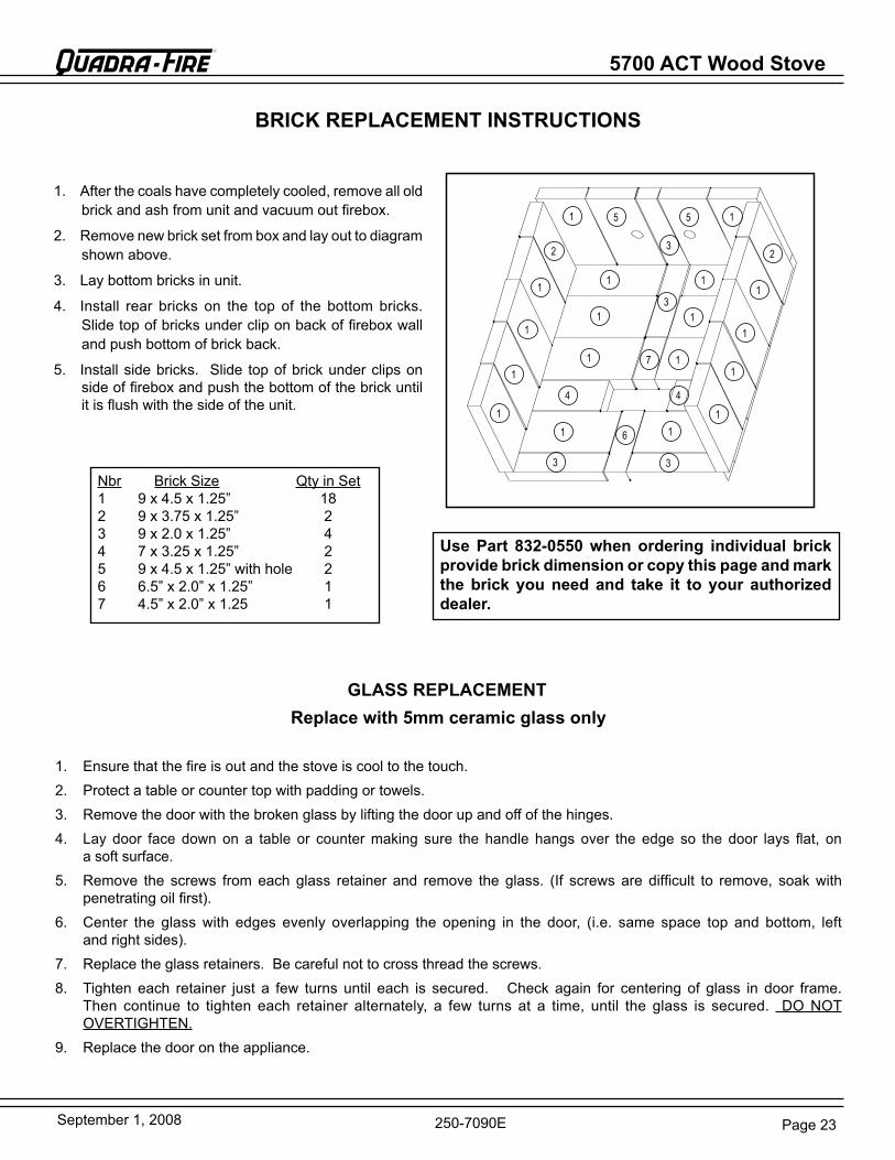
Page 23September 1, 2008
5700 ACT Wood Stove R
250-7090e
BRICk REPLACEMENT INSTRUCTIONS
Use Part 832-0550 when ordering individual brick provide brick dimension or copy this page and mark the brick you need and take it to your authorized dealer.
3 3
3
3
1
1
1
11
1
1
1
1
1
1
1
1
1
1
1
11
7
44
2 2
5 5
6
1. After the coals have completely cooled, remove all old brick and ash from unit and vacuum out firebox.
2. remove new brick set from box and lay out to diagram shown above.
3. Lay bottom bricks in unit.
4. Install rear bricks on the top of the bottom bricks. Slide top of bricks under clip on back of firebox wall and push bottom of brick back.
5. Install side bricks. Slide top of brick under clips on side of firebox and push the bottom of the brick until it is flush with the side of the unit.
Nbr brick Size Qty in Set1 9 x 4.5 x 1.25” 182 9 x 3.75 x 1.25” 23 9 x 2.0 x 1.25” 44 7 x 3.25 x 1.25” 25 9 x 4.5 x 1.25” with hole 26 6.5” x 2.0” x 1.25” 17 4.5” x 2.0” x 1.25 1
GLASS REPLACEMENTReplace with 5mm ceramic glass only
1. ensure that the fire is out and the stove is cool to the touch.2. Protect a table or counter top with padding or towels.3. remove the door with the broken glass by lifting the door up and off of the hinges.4. Lay door face down on a table or counter making sure the handle hangs over the edge so the door lays flat, on
a soft surface. 5. remove the screws from each glass retainer and remove the glass. (If screws are difficult to remove, soak with
penetrating oil first).6. Center the glass with edges evenly overlapping the opening in the door, (i.e. same space top and bottom, left
and right sides).7. replace the glass retainers. be careful not to cross thread the screws.8. Tighten each retainer just a few turns until each is secured. Check again for centering of glass in door frame.
Then continue to tighten each retainer alternately, a few turns at a time, until the glass is secured. DO NOT OVerTIgHTeN.
9. replace the door on the appliance.

5700 ACT Wood Stove
Page 24 September 1, 2008
R
250-7090e
FIGURE 24C - Baffle with ceramic blanket on top.
Allen wrench on retainer bolt
First tube has larger holes
FIGURE 24B - Allen wrench on retainer bolt.
DOOR HANDLE ASSEMBLY
1. remove all ash from the firebox, and extinguish all hot embers before disposal into a metal container.
2. With a 3/16” allen wrench, remove the 2 front secondary combustion tube retainer bolts on the secondary air channel under the end of the front tubes. See Figure 24B. NOTe: Soak the bolts with penetrating oil for at least 15 minutes before trying to remove them.
3. To remove the secondary combustion tubes, slide the tube to one side until one end is out of its hole. Then, while lifting that end of the baffle, pull the tube up over the secondary air channel and out of the hole at the other end.
NOTE: When replacing the secondary tubes, be sure the tube with the larger holes is placed in the front or your stove will not operate properly.
4. Slide baffle and ceramic blanket forward to front of stove, tilt down and slide to the door. Tilt to one side and slide both through door at the same time. Keep them tilted as you lift it out of the door. See Figure 24C.
5. To install the baffle and ceramic blanket, repeat steps 2 through 4 in reverse. be sure that the fiber board baffle is pushed back fully and the blanket is down flat. The front of the blanket should be flush with the front of the baffle.
BAFFLE REMOVAL AND INSTALLATION
1. Install washer on door handle shaft.
2. Slide door handle through door.
3. Install second washer(s) as shown.
4. Install key in groove.
5. Align groove in latch cam with key; slide latch cam over shaft.
6. Install secondary latch included in the Component Pack inside the firebox.
7. Install locknut.
CAUTION! DO NOT OVERTIGHTEN LOCkNUT. DOOR HANDLE NEEDS TO MOVE SMOOTHLY.
8. Install spring handle turning in a counter-clockwise motion on handle leaving a 3” (76mm) clearance from bend in door handle rod to end of spring handle. See Figure 24.
SPRING HANDLE WARNING! 3” (76mm) clearance is required from bend in Door Handle Rod to end of the Spring Handle. If installed within that 3” (76mm) area, Spring Handle will get hot and may cause injury.
NOTE: SEE PAGE 18 FOR OPERATING INSTRUCTIONS
FIGURE 24A
Locknut
Door Cross Section (example)Latch Cam
Spacing Washers
Square Key
Door Handle
Spring Handle
3" (76mm) clearance required from bend in Door
Handle Rod to end of Spring Handle.
Secondary Latch
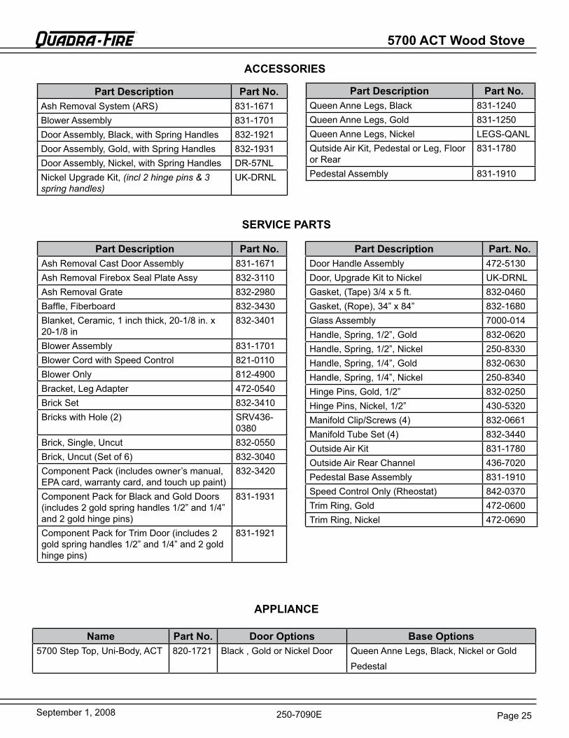
Page 25September 1, 2008
5700 ACT Wood Stove R
250-7090e
ACCESSORIES
APPLIANCE
Part Description Part No.Ash removal Cast Door Assembly 831-1671Ash removal Firebox Seal Plate Assy 832-3110Ash removal grate 832-2980baffle, Fiberboard 832-3430blanket, Ceramic, 1 inch thick, 20-1/8 in. x 20-1/8 in
832-3401
blower Assembly 831-1701blower Cord with Speed Control 821-0110blower Only 812-4900bracket, Leg Adapter 472-0540brick Set 832-3410bricks with Hole (2) SrV436-
0380brick, Single, Uncut 832-0550brick, Uncut (Set of 6) 832-3040Component Pack (includes owner’s manual, ePA card, warranty card, and touch up paint)
832-3420
Component Pack for black and gold Doors (includes 2 gold spring handles 1/2” and 1/4” and2goldhingepins)
831-1931
Component Pack for Trim Door (includes 2 gold spring handles 1/2” and 1/4” and 2 gold hingepins)
831-1921
Part Description Part. No.Door Handle Assembly 472-5130Door, Upgrade Kit to Nickel UK-DrNLgasket, (Tape) 3/4 x 5 ft. 832-0460gasket, (rope), 34” x 84” 832-1680glass Assembly 7000-014Handle, Spring, 1/2”, gold 832-0620Handle, Spring, 1/2”, Nickel 250-8330Handle, Spring, 1/4”, gold 832-0630Handle, Spring, 1/4”, Nickel 250-8340Hinge Pins, gold, 1/2” 832-0250Hinge Pins, Nickel, 1/2” 430-5320Manifold Clip/Screws (4) 832-0661Manifold Tube Set (4) 832-3440Outside Air Kit 831-1780Outside Air rear Channel 436-7020Pedestal base Assembly 831-1910Speed Control Only (rheostat) 842-0370Trim ring, gold 472-0600Trim ring, Nickel 472-0690
SERVICE PARTS
Part Description Part No.Ash removal System (ArS) 831-1671blower Assembly 831-1701Door Assembly, black, with Spring Handles 832-1921Door Assembly, gold, with Spring Handles 832-1931Door Assembly, Nickel, with Spring Handles Dr-57NLNickel Upgrade Kit, (incl 2 hinge pins & 3 spring handles)
UK-DrNL
Part Description Part No.Queen Anne Legs, black 831-1240Queen Anne Legs, gold 831-1250Queen Anne Legs, Nickel LegS-QANLQutside Air Kit, Pedestal or Leg, Floor or rear
831-1780
Pedestal Assembly 831-1910
Name Part No. Door Options Base Options5700 Step Top, Uni-body, ACT 820-1721 black , gold or Nickel Door Queen Anne Legs, black, Nickel or gold
Pedestal
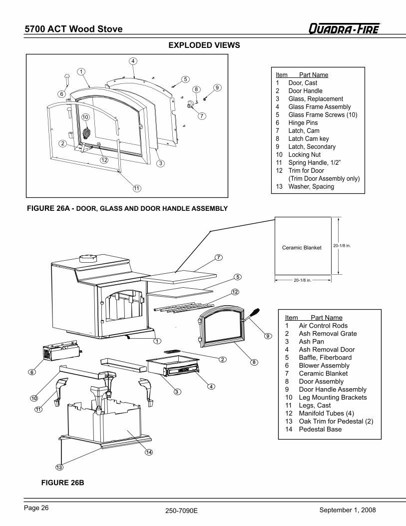
5700 ACT Wood Stove
Page 26 September 1, 2008
R
250-7090e
20-1/8 in.
20-1/8 in.
Ceramic blanket
1
2
3
4
5
6
7
8 9
10
11
12
Item Part Name1 Air Control rods2 Ash removal grate3 Ash Pan4 Ash removal Door5 baffle, Fiberboard6 blower Assembly7 Ceramic blanket8 Door Assembly9 Door Handle Assembly10 Leg Mounting brackets11 Legs, Cast12 Manifold Tubes (4)13 Oak Trim for Pedestal (2)14 Pedestal base
1
11
2
34
5
6
7
8
9
10
12
13
14
EXPLODED VIEWS
Item Part Name1 Door, Cast2 Door Handle3 glass, replacement4 glass Frame Assembly5 glass Frame Screws (10)6 Hinge Pins7 Latch, Cam 8 Latch Cam key9 Latch, Secondary10 Locking Nut11 Spring Handle, 1/2”12 Trim for Door (Trim Door Assembly only)13 Washer, Spacing
FIGURE 26A - DOOR, GLASS AND DOOR HANDLE ASSEMBLY
FIGURE 26B
Page 27September 1, 2008
5700 ACT Wood Stove R
250-7090e
Date of Service Performed By Description of Service
Service And Maintenance Log
5700 ACT Wood Stove
Page 28 September 1, 2008
R
250-7090e
Date of Service Performed By Description of Service
Service And Maintenance Log (Cont’d)
Page 29September 1, 2008
5700 ACT Wood Stove R
250-7090e
Homeowner’s Notes
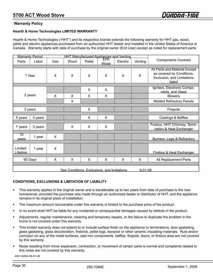
5700 ACT Wood Stove
Page 30 September 1, 2008
R
250-7090e
Warranty Policy
Hearth & Home Technologies LIMITED WARRANTY
Hearth & Home Technologies (“HHT”) and its respective brands extends the following warranty for HHT gas, wood, pellet and electric appliances purchased from an authorized HHT dealer and installed in the United States of America or Canada. Warranty starts with date of purchase by the original owner (end User) except as noted for replacement parts.
Warranty Period HHT Manufactured Appliances and VentingComponents CoveredParts Labor gas Wood Pellet ePA
Wood electric Venting
1 Year X X X X X X
All Parts and Material except as covered by Conditions, exclusion, and Limitations
listed
2years X X Igniters, electronic Compo-
nents, and glassX X X X blowers X Molded refractory Panels
3years X Firepots
5years 3years X X Castings & baffles
7years 3years X X X Firebox, HHT Chimney, Termi-
nation & Heat exchanger
10years 1year X burners, Logs & refractory
Limited Lifetime
1year X Firebox & Heat exchanger
90Days X X X X X X All replacement Parts
See Conditions, exclusions, and limitations. 9-01-08
CONDITIONS, EXCLUSIONS & LIMITATION OF LIABILITY
This warranty applies to the original owner and is transferable up to two years from date of purchase to the new homeowner, provided the purchase was made through an authorized dealer or distributor of HHT, and the appliance remains in its original place of installation.
The maximum amount recoverable under this warranty is limited to the purchase price of the product.
In no event shall HHT be liable for any incidental or consequential damages caused by defects in the product.
Adjustments, regular maintenance, cleaning and temporary repairs, or the failure to duplicate the problem in the home is not covered under this warranty.
This limited warranty does not extend to or include surface finish on the appliance or terminations, door gasketing, glass gasketing, glass discoloration, firebrick, pellet logs, kaowool or other ceramic insulating materials. rust and/or corrosion on any of the metal surfaces, cast iron components, baffles, firepots, doors, or firebox area are not covered by this warranty.
Noise resulting from minor expansion, contraction, or movement of certain parts is normal and complaints related to this noise are not covered by this warranty.
4021-645A 09-01-08
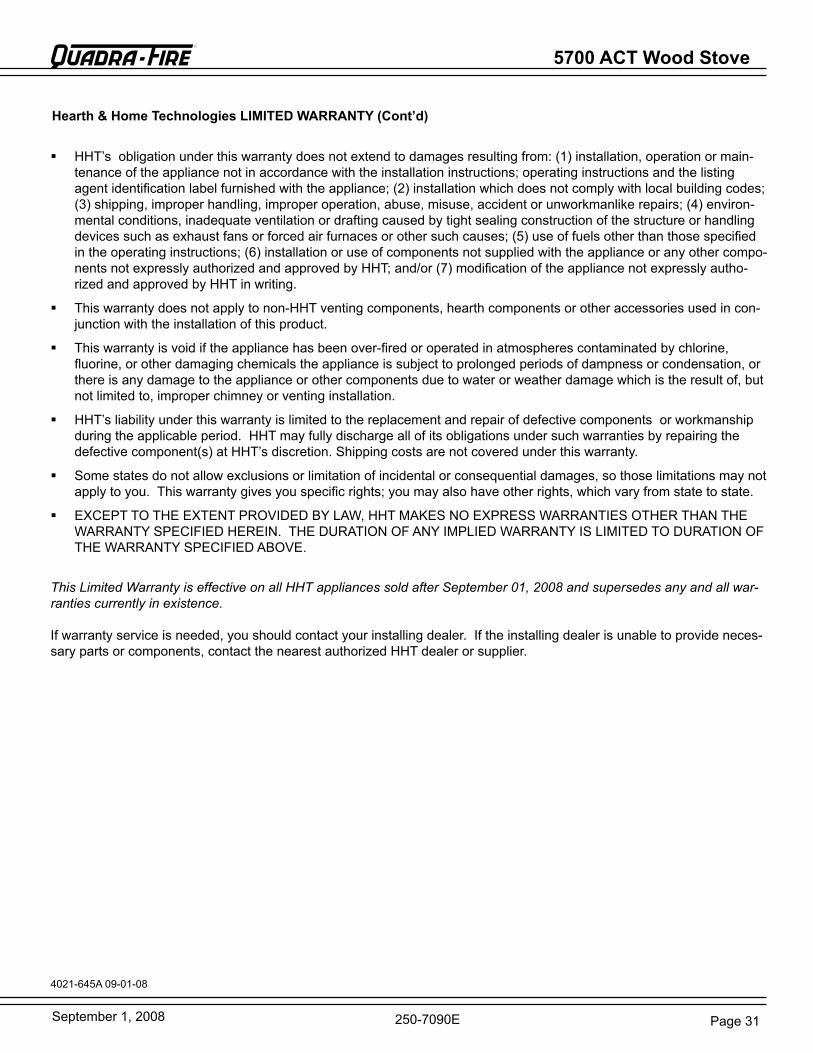
Page 31September 1, 2008
5700 ACT Wood Stove R
250-7090e
HHT’s obligation under this warranty does not extend to damages resulting from: (1) installation, operation or main-tenance of the appliance not in accordance with the installation instructions; operating instructions and the listing agent identification label furnished with the appliance; (2) installation which does not comply with local building codes; (3) shipping, improper handling, improper operation, abuse, misuse, accident or unworkmanlike repairs; (4) environ-mental conditions, inadequate ventilation or drafting caused by tight sealing construction of the structure or handling devices such as exhaust fans or forced air furnaces or other such causes; (5) use of fuels other than those specified in the operating instructions; (6) installation or use of components not supplied with the appliance or any other compo-nents not expressly authorized and approved by HHT; and/or (7) modification of the appliance not expressly autho-rized and approved by HHT in writing.
This warranty does not apply to non-HHT venting components, hearth components or other accessories used in con-junction with the installation of this product.
This warranty is void if the appliance has been over-fired or operated in atmospheres contaminated by chlorine, fluorine, or other damaging chemicals the appliance is subject to prolonged periods of dampness or condensation, or there is any damage to the appliance or other components due to water or weather damage which is the result of, but not limited to, improper chimney or venting installation.
HHT’s liability under this warranty is limited to the replacement and repair of defective components or workmanship during the applicable period. HHT may fully discharge all of its obligations under such warranties by repairing the defective component(s) at HHT’s discretion. Shipping costs are not covered under this warranty.
Some states do not allow exclusions or limitation of incidental or consequential damages, so those limitations may not apply to you. This warranty gives you specific rights; you may also have other rights, which vary from state to state.
eXCePT TO THe eXTeNT PrOVIDeD bY LAW, HHT MAKeS NO eXPreSS WArrANTIeS OTHer THAN THe WArrANTY SPeCIFIeD HereIN. THe DUrATION OF ANY IMPLIeD WArrANTY IS LIMITeD TO DUrATION OF THe WArrANTY SPeCIFIeD AbOVe.
This Limited Warranty is effective on all HHT appliances sold after September 01, 2008 and supersedes any and all war-ranties currently in existence.
If warranty service is needed, you should contact your installing dealer. If the installing dealer is unable to provide neces-sary parts or components, contact the nearest authorized HHT dealer or supplier.
4021-645A 09-01-08
Hearth & Home Technologies LIMITED WARRANTY (Cont’d)
Page 32 September 1, 2008250-7090e
R
• Do NOT discard this manual.• Important operating and maintenance
instructions included.• Read, understand and follow these instruci-
tons for safe installation and operation.• Leave this manual with party responsible for
use and operation.
CAUTION
This product may be covered by one or more of the following patents: (United States) 4593510, 4686807, 4766876, 4793322,4811534,5000162,5016609,5076254,5113843,5191877,5218953,5263471,5328356,5341794,5347983,5429495,5452708,5542407,5601073,5613487,5647340,5688568,5762062,5775408,5890485,5931661,5941237,5947112,5996575,6006743,6019099,6048195,6053165,6145502,6170481,6237588,6296474,6374822,6413079,6439226, 6484712, 6543698, 6550687, 6601579, 6672860, 6688302b2, 6715724b2, 6729551, 6736133, 6748940, 6748942, D320652, D445174, D462436; (Canada)1297749, 2195264, 2225408; or other U.S. and foreign patents pending.
Hearth & Home Technologies1445 North HighwayColville, WA 99114
Division of HNI INDUSTRIES
CONTACT INFORMATION:
Please contact your Quadra-Fire dealer with any questions or concerns. For the number of your nearest Quadra-Fire dealer,
visit our web site at www.quadrafire.com
DEALERSHIP WHERE PURCHASED:
______________________________________
_______________________________________
_______________________________________
DEALER TELEPHONE: __________________
Your Records for Model:
SERIAL NUMBER: __________________
DATE PURCHASED: __________________
DATE INSTALLED: __________________
5700 ACT Wood Stove