5620 SAM SERVICE AWARE MANAGER 14.0R1 Commissioning … · • Nokia 1830 Photonic Service Switch 1...
42
5620 SAM SERVICE AWARE MANAGER 14.0R1 Commissioning and Power Balancing User Guide 3HE-10685-AAAA-TQZZA Issue 1 March 2016
Transcript of 5620 SAM SERVICE AWARE MANAGER 14.0R1 Commissioning … · • Nokia 1830 Photonic Service Switch 1...

5620 SAMSERVICE AWARE MANAGER14.0R1
Commissioning and PowerBalancing User Guide
3HE-10685-AAAA-TQZZA
Issue 1
March 2016
Legal notice
Nokia is a registered trademark of Nokia Corporation. Other products and company names mentioned herein may be trademarks ortradenames of their respective owners.
The information presented is subject to change without notice. No responsibility is assumed for inaccuracies contained herein.
© 2016 Nokia. All rights reserved.
5620 SAM
2 Issue 13HE-10685-AAAA-TQZZA
Contents
About this document............................................................................................................................................5
1 Introduction ....................................................................................................................................................7
1.1 Overview ...............................................................................................................................................7
1.2 Network planning and design ................................................................................................................8
1.3 Commissioning and power balancing....................................................................................................9
1.4 Workflow to commission and power balance an 1830 PSS photonic device ......................................10
2 The 5620 SAM CPB application ..................................................................................................................13
2.1 Overview .............................................................................................................................................13
2.2 Web access.........................................................................................................................................14
2.3 To start up the 5620 SAM CPB application .........................................................................................15
3 System commissioning and validation......................................................................................................17
3.1 Overview .............................................................................................................................................17
3.2 System commissioning........................................................................................................................18
3.3 To load the commissioning file ............................................................................................................20
3.4 To delete the commissioning file .........................................................................................................21
3.5 System validation ................................................................................................................................22
3.6 To validate the system.........................................................................................................................23
4 System provisioning....................................................................................................................................25
4.1 Overview .............................................................................................................................................25
4.2 Provisioning.........................................................................................................................................26
4.3 To provision a system..........................................................................................................................27
5 Power adjustment ........................................................................................................................................31
5.1 Overview .............................................................................................................................................31
5.2 Greenfield commissioning using ASE power adjustment ....................................................................32
5.3 To perform greenfield ASE power adjustment .....................................................................................33
5.4 Channel power adjustment..................................................................................................................35
5.5 To perform channel power adjustment ................................................................................................36
5620 SAM
Issue 1 33HE-10685-AAAA-TQZZA

6 System loss report and EPT upload...........................................................................................................37
6.1 Overview .............................................................................................................................................37
6.2 System loss report generation.............................................................................................................38
6.3 To generate a system loss report ........................................................................................................39
6.4 Upload configuration to the EPT .........................................................................................................40
6.5 To export a configuration to an EPT ....................................................................................................41
5620 SAM
4 Issue 13HE-10685-AAAA-TQZZA

About this document
Purpose
This guide describes how to perform commissioning and power balancing using the5620 SAM Commissioning and Power Balancing application for the 1830 PSS photonicdevices.
1830 PSS reference documentation
See the following documents for more information about the 1830 PSS:
• Nokia 1830 Photonic Service Switch 1 (PSS-1) GBEH Edge Device User Guide
• Nokia 1830 Photonic Service Switch 1 (PSS-1) MD4H Edge Device User Guide
• Nokia 1830 Photonic Service Switch (PSS-1) AHP Amplifier User Guide
• Nokia 1830 Photonic Service Switch 4 (PSS-4) User Guide
• Nokia 1830 Photonic Service Switch User Provisioning Guide
• Nokia 1830 Photonic Service Switch Product Information and Planning Guide
• Nokia 1830 Photonic Service Switch Maintenance and Trouble-Clearing Guide
• Nokia 1830 Photonic Service Switch 32/16 (PSS-32/PSS-16) Installation and SystemTurn-Up Guide
• Nokia 1830 Photonic Service Switch (PSS) Safety Guide
• Nokia 1830 Photonic Service Switch (PSS) Command Line Interface Guide
• Nokia 1830 Photonic Service Switch (PSS) TL1 Commands and Messages Guide
• Nokia 1830 Photonic Service Switch (PSS) Engineering and Planning Tool User Guide
Document support
Customer documentation and product support URLs:• Customer documentation welcome page
• Technical support
How to comment
Documentation feedback
5620 SAM
Issue 1 53HE-10685-AAAA-TQZZA

5620 SAM
6 Issue 13HE-10685-AAAA-TQZZA

1 Introduction
1.1 Overview
1.1.1 Purpose
This chapter describes the 1830 PSS network planning and provides that workflow toperform commissioning and power balancing of 1830 PSS photonic devices.
1.1.2 Contents
1.2 Network planning and design 8
1.3 Commissioning and power balancing 9
1.4 Workflow to commission and power balance an 1830 PSS photonicdevice
10
5620 SAM Introduction
Issue 1 73HE-10685-AAAA-TQZZA
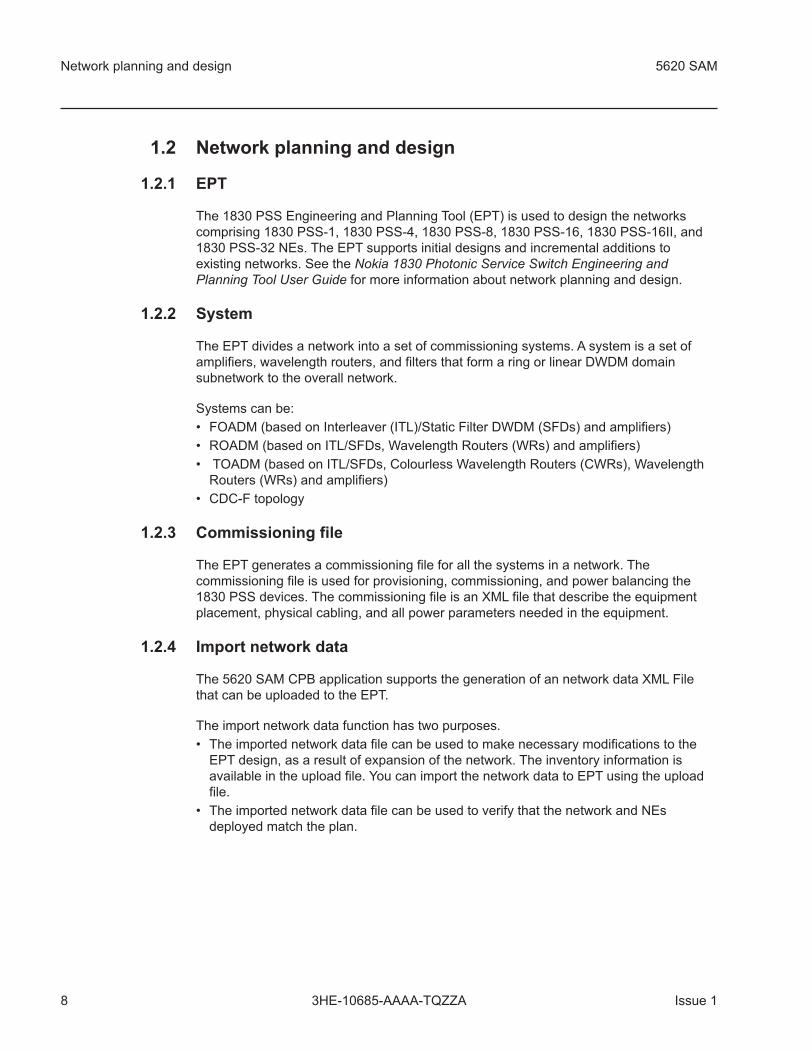
1.2 Network planning and design
1.2.1 EPT
The 1830 PSS Engineering and Planning Tool (EPT) is used to design the networkscomprising 1830 PSS-1, 1830 PSS-4, 1830 PSS-8, 1830 PSS-16, 1830 PSS-16II, and1830 PSS-32 NEs. The EPT supports initial designs and incremental additions toexisting networks. See the Nokia 1830 Photonic Service Switch Engineering andPlanning Tool User Guide for more information about network planning and design.
1.2.2 System
The EPT divides a network into a set of commissioning systems. A system is a set ofamplifiers, wavelength routers, and filters that form a ring or linear DWDM domainsubnetwork to the overall network.
Systems can be:
• FOADM (based on Interleaver (ITL)/Static Filter DWDM (SFDs) and amplifiers)
• ROADM (based on ITL/SFDs, Wavelength Routers (WRs) and amplifiers)
• TOADM (based on ITL/SFDs, Colourless Wavelength Routers (CWRs), WavelengthRouters (WRs) and amplifiers)
• CDC-F topology
1.2.3 Commissioning file
The EPT generates a commissioning file for all the systems in a network. Thecommissioning file is used for provisioning, commissioning, and power balancing the1830 PSS devices. The commissioning file is an XML file that describe the equipmentplacement, physical cabling, and all power parameters needed in the equipment.
1.2.4 Import network data
The 5620 SAM CPB application supports the generation of an network data XML Filethat can be uploaded to the EPT.
The import network data function has two purposes.
• The imported network data file can be used to make necessary modifications to theEPT design, as a result of expansion of the network. The inventory information isavailable in the upload file. You can import the network data to EPT using the uploadfile.
• The imported network data file can be used to verify that the network and NEsdeployed match the plan.
Network planning and design 5620 SAM
8 Issue 13HE-10685-AAAA-TQZZA

1.3 Commissioning and power balancing
1.3.1 5620 SAM CPB application
The 5620 SAM Commissioning and Power Balancing application automatically performsthe following for the 1830 PSS photonic devices:
• Uploads the commissioning file
• Validates the system
• Provisions the system
• Adjusts the greenfield ASE power
• Adjusts the channel power
• Generates the system loss report
• Exports the network data file to the EPT
1.3.2 Greenfield network commissioning
A greenfield network is one with no services or cross-connections in the system. Thegreenfield network commissioning process requires network connectivity between theNEs and uses ASE (Amplified Spontaneous Emission) power at each point around thering to adjust the power and commission optical connections ready for service delivery.
1.3.3 ASE
Amplified spontaneous emission (ASE) or superluminescence is light, produced byspontaneous emission, that is optically amplified by the process of stimulated emissionin a gain medium.
5620 SAM Commissioning and power balancing
Issue 1 93HE-10685-AAAA-TQZZA

1.4 Workflow to commission and power balance an 1830 PSSphotonic device
1.4.1 Workflow
The workflow to commission and power balance an 1830 PSS photonic device using the5620 SAM CPB application is as shown in Figure 1, “CPB workflow” (p. 10).
1.4.2 Stages
1
Perform the network planning and design using the 1830 PSS EPT. See Nokia 1830PSS DCN Planning and Engineering Guide for more information about performingthe network planning and design.
Figure 1 CPB workflow
Workflow to commission and power balance an 1830 PSS photonic device 5620 SAM
10 Issue 13HE-10685-AAAA-TQZZA

2
Perform the commissioning and power balancing using the 5620 SAM CPBapplication.
1. Open the 5620 SAM CPB application. See Chapter 2, “The 5620 SAM CPBapplication” for more information.
2. Load the commissioning file generated by the EPT to the 5620 SAM CPBapplication and validate the system with respect to the commissioning file. SeeChapter 3, “System commissioning and validation” for more information.
3. Perform system provisioning with respect to the file loaded in step 1. See Chapter4, “System provisioning” for more information.
4. Power balance using greenfield ASE or channel power. See Chapter 5, “Poweradjustment” for more information.
5. Generate loss report, as required. See 6.2 “System loss report generation” (p. 38)for more information.
3
Deploy and operate the 5620 SAM to perform network management. See the 5620SAM Optical User Guide for more information.
4
Upload inventory and configuration information to the EPT using the 5620 SAM CPBapplication. See 6.4 “Upload configuration to the EPT” (p. 40) for more information.
5620 SAM Workflow to commission and power balance an 1830 PSS photonic device
Issue 1 113HE-10685-AAAA-TQZZA

Workflow to commission and power balance an 1830 PSS photonic device 5620 SAM
12 Issue 13HE-10685-AAAA-TQZZA
2 The 5620 SAM CPB application
2.1 Overview
2.1.1 Purpose
This chapter provides the procedure to start up the 5620 SAM CPB application.
2.1.2 Contents
2.2 Web access 14
2.3 To start up the 5620 SAM CPB application 15
5620 SAM The 5620 SAM CPB application
Issue 1 133HE-10685-AAAA-TQZZA
2.2 Web access
2.2.1 Web server
The 5620 SAM CPB application has a web presentation layer that is viewed in abrowser. The CPB application uses a common web server that is integrated with 5620SAM.
2.2.2 Supported browsers
The 5620 SAM CPB application is supported on the following browsers:
• Microsoft Internet Explorer 11
• Latest version of Mozilla Firefox
• Latest version of Google Chrome
Note: When both the active and standby 5620 SAM servers are up, you can connect toeither to open the application. If only one of the servers is up, you must connect to thatserver.
Web access 5620 SAM
14 Issue 13HE-10685-AAAA-TQZZA

2.3 To start up the 5620 SAM CPB application
2.3.1 Steps
1
Perform one of the following to start up the 5620 SAM CPB application using a webbrowser:
a. For a non-secured connection, use the browser to open the following URL:
http://server/Cpb where server is the hostname or IP address
of the 5620 SAM server (active or standby).
b. For secured connection, use the browser to open the following URL:
https://server/Cpb where server is the hostname or IP
address of the 5620 SAM server (active or standby).
Result: The following login page is displayed:
2
Enter the required username and password and click Login.
Result: The 5620 SAM CPB application starts up.
5620 SAM To start up the 5620 SAM CPB application
Issue 1 153HE-10685-AAAA-TQZZA
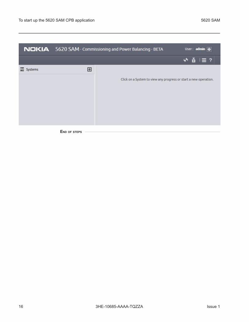
END OF STEPS
To start up the 5620 SAM CPB application 5620 SAM
16 Issue 13HE-10685-AAAA-TQZZA
3 System commissioning and validation
3.1 Overview
3.1.1 Purpose
This chapter describes the commissioning file and provides the procedures to upload thecommissioning file to the 5620 SAM CPB application and to delete a previously loadedfile.
This chapter also describes the system validation and provides the procedure to performsystem validation.
3.1.2 Contents
3.2 System commissioning 18
3.3 To load the commissioning file 20
3.4 To delete the commissioning file 21
3.5 System validation 22
3.6 To validate the system 23
5620 SAM System commissioning and validation
Issue 1 173HE-10685-AAAA-TQZZA
3.2 System commissioning
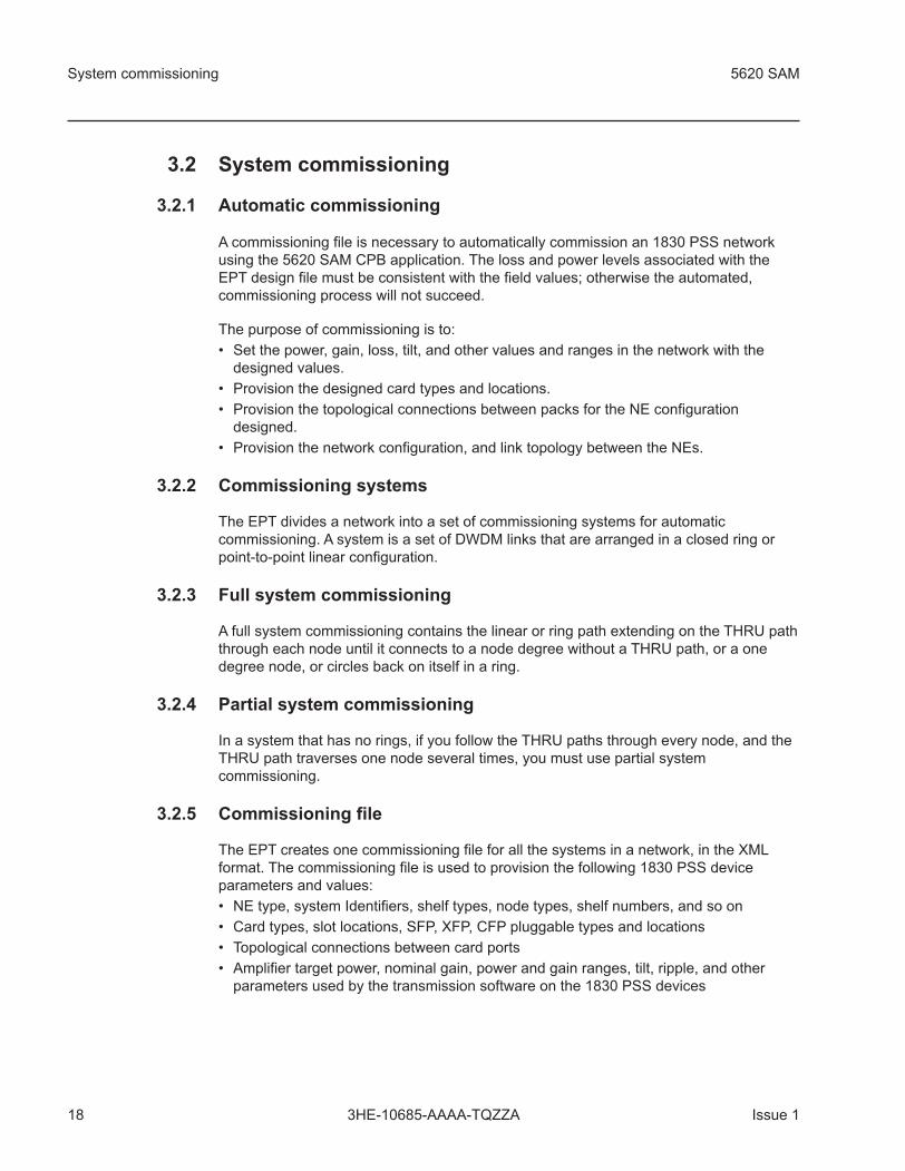
3.2.1 Automatic commissioning
A commissioning file is necessary to automatically commission an 1830 PSS networkusing the 5620 SAM CPB application. The loss and power levels associated with theEPT design file must be consistent with the field values; otherwise the automated,commissioning process will not succeed.
The purpose of commissioning is to:
• Set the power, gain, loss, tilt, and other values and ranges in the network with thedesigned values.
• Provision the designed card types and locations.
• Provision the topological connections between packs for the NE configurationdesigned.
• Provision the network configuration, and link topology between the NEs.
3.2.2 Commissioning systems
The EPT divides a network into a set of commissioning systems for automaticcommissioning. A system is a set of DWDM links that are arranged in a closed ring orpoint-to-point linear configuration.
3.2.3 Full system commissioning
A full system commissioning contains the linear or ring path extending on the THRU paththrough each node until it connects to a node degree without a THRU path, or a onedegree node, or circles back on itself in a ring.
3.2.4 Partial system commissioning
In a system that has no rings, if you follow the THRU paths through every node, and theTHRU path traverses one node several times, you must use partial systemcommissioning.
3.2.5 Commissioning file
The EPT creates one commissioning file for all the systems in a network, in the XMLformat. The commissioning file is used to provision the following 1830 PSS deviceparameters and values:
• NE type, system Identifiers, shelf types, node types, shelf numbers, and so on
• Card types, slot locations, SFP, XFP, CFP pluggable types and locations
• Topological connections between card ports
• Amplifier target power, nominal gain, power and gain ranges, tilt, ripple, and otherparameters used by the transmission software on the 1830 PSS devices
System commissioning 5620 SAM
18 Issue 13HE-10685-AAAA-TQZZA
• Network topology; that is, the NE-to-NE fiber links and orientation with respect to eachother
• Port-to-port and fiber span loss information
• Optical Channel Power Offsets
The commissioning file is uploaded to the 5620 SAM CPB application and is used forcommissioning the systems. The 5620 SAM CPB application can commission multiplesystems simultaneously, and reducing the total commissioning time.
5620 SAM System commissioning
Issue 1 193HE-10685-AAAA-TQZZA
3.3 To load the commissioning file
3.3.1 Before you begin
Ensure that:
• 1830 PSS devices are discovered from the 5620 SAM. See the 5620 SAM OpticalUser Guide for more information about NE mediation and device discovery.
• device names are aligned with the names defined in the EPT.
3.3.2 Steps
Perform the following to load the commissioning file to the 5620 SAM CPB application.
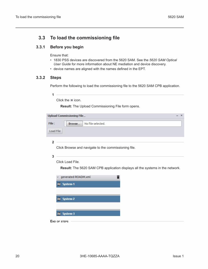
1
Click the icon.
Result: The Upload Commissioning File form opens.
2
Click Browse and navigate to the commissioning file.
3
Click Load File.
Result: The 5620 SAM CPB application displays all the systems in the network.
END OF STEPS
To load the commissioning file 5620 SAM
20 Issue 13HE-10685-AAAA-TQZZA

3.4 To delete the commissioning file
3.4.1 Steps
1
Click the delete icon in the left panel of the 5620 SAM CPB application.
Result: A confirmation dialog box appears.
2
Click Yes to remove the commissioning file and all the systems from the server.
END OF STEPS
5620 SAM To delete the commissioning file
Issue 1 213HE-10685-AAAA-TQZZA

3.5 System validation
3.5.1 Validation process
After the system is loaded, perform validation to ensure that the EPT plan matches thenode inventory before performing the provisioning and power balancing. After thevalidation, a discrepancy report is generated that is used to correct the errors. Thesystem validation process helps to reduce the chance of discovering an error later in thecycle.
The validation process involves querying the 5620 SAM database, comparing thefollowing, as currently provisioned, against those specified in the commissioning file:
• shelves
• card slots
• internal topologies
• external topologies
System validation 5620 SAM
22 Issue 13HE-10685-AAAA-TQZZA

3.6 To validate the system
3.6.1 Steps
1
Click on the system in the list of systems under the required commissioning file inthe Systems panel.
2
Hover over the system icon.
3
Click on the Perform System Validation icon.
Result: The validation results are displayed for the system and the nodes.
4
Click on the individual node to display the errors.
Result: The errors are displayed as follows:
5620 SAM To validate the system
Issue 1 233HE-10685-AAAA-TQZZA

The result of system validation can be one of the following:
• — validation is in progress.
• — validation has completed successfully.
• — validation did not complete and has an error. If there is an error, click on thesystem or node status tab to troubleshoot the cause of the error and perform thevalidation again.
END OF STEPS
To validate the system 5620 SAM
24 Issue 13HE-10685-AAAA-TQZZA

4 System provisioning
4.1 Overview
4.1.1 Purpose
This chapter describes provisioning systems in a network and how to perform theprovisioning using the CPB application.
4.1.2 Contents
4.2 Provisioning 26
4.3 To provision a system 27
5620 SAM System provisioning
Issue 1 253HE-10685-AAAA-TQZZA

4.2 Provisioning
4.2.1 Overview
The provisioning option in the CPB application provisions the NEs in a network asconfigured in the commissioning file. You can provision the system after the systemvalidation is completed. In this part of commissioning a network, the cards, ports, opticallinks, and power attributes are provisioned.
4.2.2 Provisioning steps in 5620 SAM CPB application
Provisioning a system includes the following steps:
• Querying inventory — The inventory information from the uploaded commissioning fileis collected.
• Provisioning inventory — The shelves and cards of all the devices in the systems ofthe network are provisioned as per the design in the uploaded commissioning file.
• Waiting for ports — CPB waits for the ports to be configured as per the commissioningfile.
• Provision external topology — The external optical links are configured.
• Provision internal topology — The internal optical links are configured.
• Provision SEAM topology — The SEAM topology is configured between the THRUports of a WR or CWR card between two systems.
• Provision power attributes — The power attributes such as power gain and nominalloss, are provisioned.
Provisioning 5620 SAM
26 Issue 13HE-10685-AAAA-TQZZA

4.3 To provision a system
4.3.1 Steps
1
Click on a system in the list of systems under the required commissioning file in theSystems panel.
2
Hover over the system icon.
3
Click on the provisioning system icon. By default, all available nodes in a systemare added in the Selected Nodes list in the Select Nodes step on the main window.
4
Use the arrow icons between the All Nodes and Selected Nodes lists to move thenodes to and from the lists, as required.
5
Click Choose Options and perform one of the following:
a. Click Select Defaults to choose the default provisioning options.
b. Click Select All to choose all provisioning options.
c. Configure the parameters:
• Pre provision cards – if a slot in a node is programmed as empty and the planspecifies a card for that slot, the application sets the programmed card type forthat slot to match the plan (i.e. preprovision the slot).
5620 SAM To provision a system
Issue 1 273HE-10685-AAAA-TQZZA

• Set non-OT ports 'admin up' – the application sets the administrative state toup for every port (with the topology connection) in the node that is a non OTcard .
d. Click Clear All to choose the provisioning options that you require.
Result:
6
Click Choose Power Parameters and select power parameters in one of thefollowing ways.
a. Click Select Defaults to choose the default parameter options.
b. Click Select All to choose all parameter options.
The following parameters are configured:
• WT Decoder Usage Type
• Gain Adjust Sched Base
• WTOCM Conn Loss
• Gain Adjust Timer Period
• Gain Adjust Timer Length
• Gain Adjust Auto Enabled
• Ingress SRS Tilt Post Fraction
• Egress SRS Tilt Pre Fraction
• Egress SRS Tilt Calc Output Loss
• SRS Tilt Adjust Auto Enabled
• LH Launch Attenuation
• IROADM
c. Click Clear All to choose the parameter options that you require.
Result:
To provision a system 5620 SAM
28 Issue 13HE-10685-AAAA-TQZZA
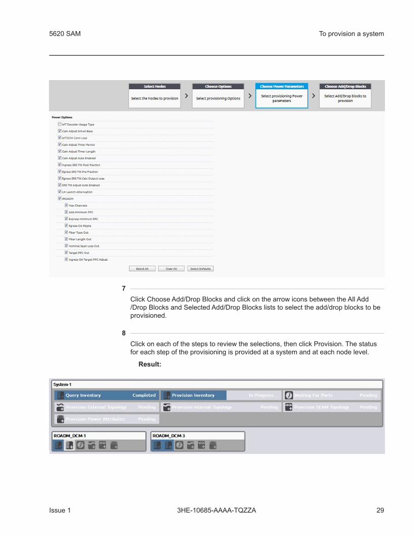
7
Click Choose Add/Drop Blocks and click on the arrow icons between the All Add/Drop Blocks and Selected Add/Drop Blocks lists to select the add/drop blocks to beprovisioned.
8
Click on each of the steps to review the selections, then click Provision. The statusfor each step of the provisioning is provided at a system and at each node level.
Result:
5620 SAM To provision a system
Issue 1 293HE-10685-AAAA-TQZZA

9
Click on the system or node status tab to get more information about theprovisioning status of the system or nodes.
Result:
The result of system provisioning can be one of the following:
• — provisioning is in progress.
• — provisioning has completed successfully.
• — provisioning did not complete and has an error. If there is an error, click onthe system or node status tab to troubleshoot the cause of the error and performprovisioning again.
END OF STEPS
To provision a system 5620 SAM
30 Issue 13HE-10685-AAAA-TQZZA
5 Power adjustment
5.1 Overview
5.1.1 Purpose
You can perform power adjustment using greenfield ASE power or channel power. Thischapter describes both greenfield ASE power adjustment and in-service channel poweradjustment.
5.1.2 Contents
5.2 Greenfield commissioning using ASE power adjustment 32
5.3 To perform greenfield ASE power adjustment 33
5.4 Channel power adjustment 35
5.5 To perform channel power adjustment 36
5620 SAM Power adjustment
Issue 1 313HE-10685-AAAA-TQZZA

5.2 Greenfield commissioning using ASE power adjustment
5.2.1 Greenfield network and ASE power
A greenfield network is one that has no services or cross-connects. Greenfield networkcommissioning requires network connectivity between the NEs and uses the ASE powergenerated by line drivers in the system to adjust power levels and commission opticalconnections ready for service delivery.
You can commission a greenfield using ASE power adjustment in two ways using theCPB application:
• clean slate
• continue
A clean slate commissioning resets the commissioned flags on the nodes of the systemand performs the power adjustment from the beginning.
A continued commissioning performs the power adjustment on the nodes that were notcommissioned previously.
5.2.2 Greenfield ASE power adjustment steps in CPB
Greenfield ASE power adjustment includes the following steps:
• Querying inventory — The inventory information from the uploaded commissioning fileis collected.
• Verifying card admin up — The administrative status of the cards are verified.
• Setting NE not commissioned — The commissioning flag on the system is set to notcommissioned.
• Performing ASE power adjustment — The ASE power adjustment is performed.
• Setting NE commissioned — The commissioning flag on the system is set tocommissioned.
• Creating system loss report — The system loss report is generated.
Greenfield commissioning using ASE power adjustment 5620 SAM
32 Issue 13HE-10685-AAAA-TQZZA
5.3 To perform greenfield ASE power adjustment
5.3.1 Steps
1
Click on a system in the list of systems under the required commissioning file in theSystems panel.
2
Hover over the system icon.
3
Click on the greenfield ASE power adjustment icon. The Choose Greenfield ASEPower Adjustment Options window opens.
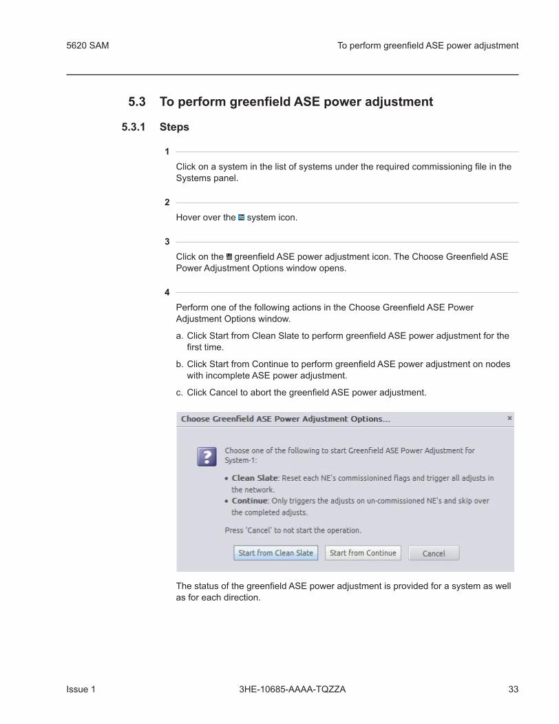
4
Perform one of the following actions in the Choose Greenfield ASE PowerAdjustment Options window.
a. Click Start from Clean Slate to perform greenfield ASE power adjustment for thefirst time.
b. Click Start from Continue to perform greenfield ASE power adjustment on nodeswith incomplete ASE power adjustment.
c. Click Cancel to abort the greenfield ASE power adjustment.
The status of the greenfield ASE power adjustment is provided for a system as wellas for each direction.
5620 SAM To perform greenfield ASE power adjustment
Issue 1 333HE-10685-AAAA-TQZZA

5
Click on the system or the direction status tab to get more information about thegreenfield ASE power adjustment status of the system or direction.
Result:
The result of greenfield ASE power adjustment can be one of the following:
• — adjustment is in progress.
• — adjustment has completed successfully.
• — adjustment did not complete and has an error. If there is an error, click onthe system or direction status tab to troubleshoot the cause of the error andperform greenfield ASE power adjustment again.
END OF STEPS
To perform greenfield ASE power adjustment 5620 SAM
34 Issue 13HE-10685-AAAA-TQZZA
5.4 Channel power adjustment
5.4.1 In-service channel power
You can use the channel power adjustment option of the 5620 SAM CPB application toperform in-service channel power adjustment in a system. While performing this task, thechannel power levels are adjusted to attempt to reach target levels using a wavelengthservice created through all nodes defined in the commissioning file.
5.4.2 Channel power adjustment steps in CPB
Channel power adjustment includes the following steps:
• Querying inventory — The inventory information from the uploaded commissioning fileis collected.
• Verifying card admin up — The administrative status of the cards are verified.
• Setting NE not commissioned — The commissioning flag on the system is set to notcommissioned.
• Performing in-service power adjust — The in-service channel power adjustment isperformed.
• Setting NE commissioned — The commissioning flag on the system is set tocommissioned.
• Creating power adjust report — The power adjustment report is generated.
5620 SAM Channel power adjustment
Issue 1 353HE-10685-AAAA-TQZZA

5.5 To perform channel power adjustment
5.5.1 Steps
1
Click on a system in the list of systems under the required commissioning file in theSystems panel.
2
Hover over the system icon.
3
Click on the channel power adjust icon. The Start Channel Power Adjustmentwindow opens.
4
Perform one of the following actions in the Start Channel Power Adjustment window.
a. Click Start to begin the channel power adjustment.
b. Click Cancel to abort the channel power adjustment.
The status of the channel power adjustment is provided for the system and for eachdirection.
5
Click on the system or direction status tab to get more information about the channelpower adjustment status of the system or direction.
Result:
The result of channel power adjustment can be one of the following:
• — adjustment is in progress.
• — adjustment has completed successfully.
• — adjustment did not complete and has an error. If there is an error, click onthe system or direction status tab to troubleshoot the cause of the error andperform channel power adjustment again.
END OF STEPS
To perform channel power adjustment 5620 SAM
36 Issue 13HE-10685-AAAA-TQZZA
6 System loss report and EPT upload
6.1 Overview
6.1.1 Purpose
A system loss can be generated irrespective of whether the validation, provisioning, andpower balancing is completed successfully. This chapter describes system loss reportingand how to generate a system loss report using the CPB application and how to uploadconfiguration information to the EPT.
6.1.2 Contents
6.2 System loss report generation 38
6.3 To generate a system loss report 39
6.4 Upload configuration to the EPT 40
6.5 To export a configuration to an EPT 41
5620 SAM System loss report and EPT upload
Issue 1 373HE-10685-AAAA-TQZZA

6.2 System loss report generation
6.2.1 System loss report
The CPB application can generate a loss report for a system and each of the add/dropblocks in the system in both A to Z and Z to A directions.
6.2.2 Loss report parameters
The report includes ingress and egress ports, actual loss, PT Min loss, PT Max loss,nominal loss, loss value, and notes with additional information. The following tabledescribes the fields of the loss report table.
Field Description
From Starting point for the measured loss
To End point for the measured loss
Actual Loss (dB) Measured loss between the ports
PT Min Loss (dB) Minimum expected card or span loss used to plan thenetwork
PT Max Loss (dB) Maximum expected card or span loss used to plan thenetwork
Nominal Loss (dB) Nominal card or span loss used to plan the network
Loss Value How the loss value reported was obtained
Notes Additional information
System loss report generation 5620 SAM
38 Issue 13HE-10685-AAAA-TQZZA

6.3 To generate a system loss report
6.3.1 Steps
1
Click on a system in the list of systems under the required commissioning file in theSystems panel.
2
Hover over the system icon.
3
Click on the generate system loss icon. The loss report for the system and each ofthe add/drop blocks in the system is displayed.
Result: When the topology spanned is between two nodes in the system, thecorresponding row is shown in bold.
The result of system loss report generation can be one of the following:
• — report generation is in progress.
• — report generation has completed successfully.
END OF STEPS
5620 SAM To generate a system loss report
Issue 1 393HE-10685-AAAA-TQZZA
6.4 Upload configuration to the EPT
6.4.1 Export an EPT upload file
The 1830 PSS devices can be automatically commissioned using the commissioning filecreated from the EPT. An extension of the network or a modification requiresrecommissioning the network. The EPT design file should be updated before creating anew commissioning file.
The Export EPT upload file option in the 5620 SAM CPB application exports networkinformation from the 1830 PSS network. The upload file is an XML file that containsinventory and configuration information that is used to update a previously created EPTdesign file.
6.4.2 Replanning a network
The network replanning can be performed to:
• change amplifier type
• add or remove a node in a ring or linear chain
• replace a fiber segment
• change the number of channels (migrate from 44 to 88 channels)
After the EPT design modifications are completed, bring the design to a complete orvalid state again using the modified design in the EPT. If the network has demanddeployments that are not reflected in the current EPT design file, you can use the uploadfile generated by the 5620 SAM CPB application to check the EPT design against thephysical network, and add the additional demands from the physical network to the EPTdesign file.
Upload configuration to the EPT 5620 SAM
40 Issue 13HE-10685-AAAA-TQZZA
6.5 To export a configuration to an EPT
6.5.1 Steps
1
On the toolbar, click on the export EPT upload icon to export the configuration onthe CPB application to the EPT.
Result: The network design file is downloaded in XML format.
END OF STEPS
5620 SAM To export a configuration to an EPT
Issue 1 413HE-10685-AAAA-TQZZA

To export a configuration to an EPT 5620 SAM
42 Issue 13HE-10685-AAAA-TQZZA