
56 & 66 Series industrial switchgear, the driving force ...systemcontrols.co.in/datasheet/CLIPSAL...
102
The driving force behind today's industry. SERIES industrial switchgear 56 & 66 technical data clipsal.com
Transcript of 56 & 66 Series industrial switchgear, the driving force ...systemcontrols.co.in/datasheet/CLIPSAL...

The driving force behind today's industry.
SERIESindustrial switchgear
56 &&66
tech
nica
l da
ta
clipsal.com

C O N T E N T Spage
66 Series Industrial Switchgear
44 66CV Switched Socket Outlets 66P Series Straight Plugs
45 Internal Socket and Pin Housings 66P Series Pin Confi gurations
Technical Information
46 Lloyd’s Register Approvals for 56 Series Department of Industrial Relations Approvals for 56 Series
47 Plug Confi gurations Socket Confi gurations
48 Technical Drawings
93 International Protection Ratings
94 Technical Terms
95 Technical Tables Useful Formulae Abbreviations
96 Common Conversion Factors
97 Numerical Index
C O N T E N T S
56 Series Industrial Switchgear
2 Introduction
8 Ready Reference Guide
10 Chemical Comparisons
12 Combination Switched Socket Outlets
14 Surface Socket Outlets
15 Appliance Inlets
16 Surface Switches
18 Changeover and Reversing Switches
19 Push-button Control Stations
20 Key Operated Switches
22 Timer Switches
24 Sunset Switches
25 Mounting Feet
Condensation Drain
Padlocking Clips
26 Angle and Straight Plugs
28 Extension Sockets and Appliance Connectors Pendant Conversion Kits
29 Pendant Outlets
30 Special Combinations and Modules
33 Transformers
Wall Lights
34 Mounting Enclosures
Anti-Corrosion Enclosure Screws
Bridges and Dividers
35 Mounting Enclosure Lids Pre-Drilled Mounting Enclosure Lids Switchgear Cover Assemblies
36 Switchgear Cover Assemblies
37 High Pressure Gaskets
38 Adaptable Enclosures Junction Boxes Two Aperture Enclosure IP66
39 Computer Surface Modules
Flush Surrounds
40 56 Series Distribution Boards
41 Armoured Cable Junction Box
42 Motor Starters
43 M56 Series Cast Metal Switches
page
industrial switchgear
SERIES56 66&&

THE DRIVING FORCE BEHIND
Designed to satisfy customer needs,
precisely engineered and carefully
manufactured, Clipsal Industrial Switchgear is
as versatile as your requirements.
Industrial switchgear, being one of the most
important components of industry, has to be tough,
safe, able to take hard knocks and give reliable
performance under many adverse conditions.
The Clipsal 56 and 66 Series satisfi es these
challenges with the use of durable engineering
plastics.
The 56 Series has been tested for protection
against ingress of water and dust to International
Protection Rating IP56, and in many instances
exceeds this level of protection.
It is testimony to the excellence in both manu-
facture and performance of 56 and 66 Series
Industrial Switchgear.
QualityEndorsedCompany
ISO 9002LIC 413
StandardsAustralia
industrial switchgear
SERIES56 66&&

TODAY’S INDUSTRY
All products in the 56 Series are available in light grey UV stabilised rigid polycarbonate. The light grey series has excellent strength compared to other compatible plastic products.
There is, however, no economical plastic material available that provides maximum impact strength as well as a high degree of chemical resistance.
Clipsal has chosen not to compromise on either count and instead offers two high performance chemical resistant ranges for environmentally aggressive locations.
The UV and chemical resistant orange and white version is suitable for indoor and outdoor applications, such as chemical plants, timber and paper processing plants and laboratories.
The new chemical resistant grey range of sockets, switched socket outlets and covers has been specifi cally designed for indoor food environments where aggressive alkalis cleaners are used, such as dairies, abattoirs and food processing plants. For further technical details refer pg 10.
StandardsPin confi gurations for plugs, sockets
and switched socket outlets comply with AS/NZS3123 and switches with appropriate parts of AS/NZS3947.3 & AS/NZS3133.
Dust-resistant,Hoseproof and UV Resistant
Because its tough enclosure casing is dust-resistant, hoseproof and UV resistant, the 56 Series is suitable for heavy industrial environments.
The aesthetic appearance of the 56 Series makes it the ideal choice for installation in commercial facilities such as television studios, shopping centres and warehouses. What’s more, 56 Series products are just as accept-able alongside a public or domestic swimming pool.
Safety in OperationFor safety’s sake all of the switches
in the range have been equipped with facilities for double pad-locking. When plugs are removed, the socket fl ap automatically locks into place, preventing dust or water from entering.
56 Series Colour RangeFor over a decade
the Clipsal 56 Series has enjoyed a reputation for excellent performance in harsh industrial environments.
PVC Solvent Bonding Compatibility
All Clipsal 56 Series Enclosures are manufactured from robust UV stabilised PVC and can be solvent bonded to standard electrical PVC conduit accessories.
Transparent Plastic Materials
The introduction of transparent materials to the 56 Series enables the inspection and checking of the compo-nents pin/socket confi guration and wiring at a glance, while still providing protection against the elements
Designed to Mix and MatchWhat suits one industry might not
be the perfect match for another. That’s why the 56 Series was specifi cally designed to mix and match. There is an extensive choice of modules available, including switches, sockets, photo electrical cells and residual current devices.
Clipsal mounting enclosures range in size from 1 to 16 gang. This allows assemblies to be customised - from a simple switch station to a large electrical control panel.
Accessories can be ordered Less Enclosure (back box) by simply specifying LE after the Catalogue Number.

4
56 Series Modules - designed to mix and match.
Clear indication of switch position.
Modular system with 1 to 16 gang arrangements to satisfy your every need.
Visible gasket - your guar-antee of sealing.
Raised lettering for long life of markings.
Optional neon indicator.
Captive stainless steel com-bination head fi xings for corrosion resistance and effortless installation.
Padlock on/off facility.
Available in high impact Grey or Chemically Resist-ant Orange/White and Grey fi nishes.
Mechanical interlock option-al to ensure power discon-nection before insertion or removal of the plug.
Transparent fl ap clearly shows pin confi guration.
Flap automatically closes to ensure IP rating is maintained.

5
Clear Pin Surround Providing quick and sure location of plug in socket and protection of pins.
Wide Lock Ring Can be tightened and unscrewed with ease, even with a gloved hand. Provides positive sealing with an in built sponge-type gasket.
Sturdy Terminal Housing For durability and years of reliable service.
Stainless Steel Combination Head Screws For corrosion resistance and easy installation.
Transparent Polycarbonate Body Allows instant inspection of connections.
2
1
Features
Cable gland extremely fl exible with positive grip to ensure dependable sealing.
Available in straight and angled versions. Angled versions enable a neat cable run straight down rather than directly out of the back of plug top.
Transparent body allows instant visual checking of connections.
Wide lock ring can be tightened and unscrewed with ease, even with a gloved hand. Provides positive sealing with inbuilt moulded rubber gasket.
Clear pin surround provides quick and sure location of plug in socket and protection of pins.
Internal cable clamp grips two ways to prevent cable twisting.
Captive stainless steel combination head screws offer corrosion resistance and easy installation.
Sturdy terminal housing for durability and years of reliable service.
IP66 Rating (in accordance with AS1939) prevents water and dust ingress.
1 2 3 4 5 6 7 8
7
6
5
2
56 Series Plugs - for strength and easy installation.
33
4
8
9

6
Clipsal design, engineering and precision brings you the revolutionary 66 Series of Combination Switched Socket Outlets and Plugs for 50 and 63 amp., 4, 5 or 7 pin heavy-duty appliances, such as welders, pumps, and mobile conveyors.
Until recently 50 and 63 amp. socket outlets and plugs were constructed with metal clad housings, which, in many situations, encounter drawbacks with their heavyweight, time consuming installation and susceptibility to corrosion.
66 Series Switched Socket Outlets and Plugs solve these problems and offer many other benefi ts.
Major features of the 66CV Switched Socket Outlets are their robust PVC back box and polyester cover that provide excellent chemical and high impact resistance as well as UV stability, in a neat, compact unit that’s quicker and easier to install. 66P Plugs are manufactured from fully moulded, transparent polycarbonate or resistant orange polyester to offer the same degree of strength and resistance to chemicals and UV rays.
For convenience and safety, both the switched socket outlets and plugs can be easily used with gloved hands.
An internal interlock is fi tted to the outlet to prevent insertion or withdrawal of the plug (provided the plug is fi tted with an interlock facility) while the switch is in the ‘on’ position.
66CV Series Combination Switched Socket Outlets also incorporate a padlock facility in the ‘off’ position for added safety and security.
industrial switchgear
SERIES66
• IP66 protection in accordance with AS 1939 for the Combination Switched Socket Outlet and also when engaged with a plug.
• Separate back box with rear wiring facility for easy installation of large diameter cables.
• 1 x M40 entry (top) and 2 x M32 entries (bottom) to assist cable termination.
• Large switch knob and socket outlet fl ap for easy operation even with gloved hand.
• Socket outlet fl ap includes a heavy spring assembly to ensure IP66 integrity.
• Confi gurations of sockets and keyways in accordance with AS 3123-1990.
• Stainless steel, combination head, captive cover screws for corrosion resistance and easy installation.
• Switch rated for motor duty, AC23 in accordance with AS/NZS 3947.3.
• Standard colour - Grey. Resis-tant Orange optional. Double insulated for operator safety.
• Interior assembly is completely removable to assist with cable entry and termination of the large conductors required for the unit.
Features
Make light work of installationswith 66 Series Combination Switched
Socket Outlets.

7
3
4
5
22
1
3 8
9
6 Clear Pin Surround Providing quick and sure location of plug in socket and protection of pins.
Wide Lock Ring Can be tightened and unscrewed with ease, even with a gloved hand. Provides positive sealing with an inbuilt sponge-type gasket.
Sturdy Terminal Housing For durability and years of reliable service.
Stainless Steel Combination Head Screws For corrosion resistance and easy installation.
Transparent Polycarbonate Body Allows instant inspection of connections.
Internal Cable Clamp Fast fi xing and grips two ways, preventing cable from twisting. IP66 Rating (in accordance with AS1939)When engaged in the 66CV switched socket outlet with the hydrant ring fully engaged, an International Protection Rating of IP66 is achieved.
Cable GlandExtremely fl exible with positive grip to ensure dependable sealing. Gland Nut with 50mm threaded cable entryFor alternative facility termination.Note - IP Ratings only apply to cable terminations as per wiring instructions.
7
Features
1 2 3 4 5 6 8 9
66P Series pulls the plug on heavy metal.

8
Combination Switched Socket Outlets 12
Versions from 250V 10A to 500V 50A. All internal phase connections between switches and sockets are factory wired. Sockets include a dustproof and hoseproof fl ap with snap latch.
Surface Socket Outlets 14
Sockets include a clear dustproof and hoseproof fl ap with snap latch. Tough polyester terminal housings.
Appliance Inlets 15
Screwed lock ring secures extension sockets and appliance connectors and ensures IP rating. Impact resistant and UV stabilised housings. Downward facing, angled pin housing available on 500V units.
Surface Switches 16
Versions from 250V 10A to 500V 63A. Positive rotary switch action. Provision for 2 padlocks.
Key Operated Switches 20
Versions from 250V 20A to 500V 50A. Available in 3 versions - Standard Security, Medium Security and High Security. Locking in ‘off’ and ‘on’ positions.
Timer Switches 22
Available in digital and mechanical versions. Digital and mechanical versions available with 150 hour battery backup.
Sunset Switches 24
Automatically turns lights on when natural light falls below a predetermined level. Suitable for surface or fl ush mounting.
The following Reference Guide has been included to help you quickly fi nd the most commonly used 56 and 66 Series Industrial Switchgear.
For fast product selectionREADY REFERENCE GUIDE
56 SERIES
••
•
•••
•
••
•••
••
•
••
•
•
Versions from 250V 10A to 500V 50A.
9
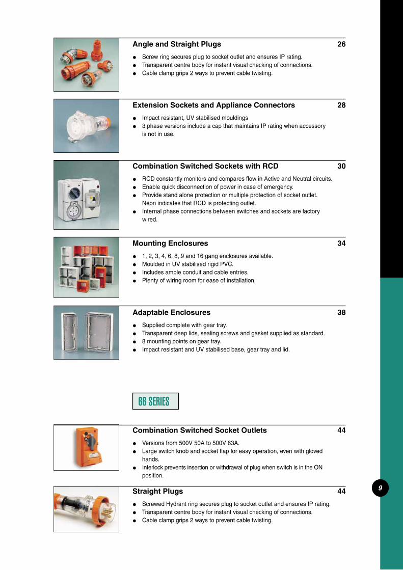
Angle and Straight Plugs 26
Screw ring secures plug to socket outlet and ensures IP rating. Transparent centre body for instant visual checking of connections. Cable clamp grips 2 ways to prevent cable twisting.
Extension Sockets and Appliance Connectors 28
Impact resistant, UV stabilised mouldings 3 phase versions include a cap that maintains IP rating when accessory is not in use.
Combination Switched Sockets with RCD 30
RCD constantly monitors and compares fl ow in Active and Neutral circuits. Enable quick disconnection of power in case of emergency. Provide stand alone protection or multiple protection of socket outlet. Neon indicates that RCD is protecting outlet. Internal phase connections between switches and sockets are factory wired.
Mounting Enclosures 34
1, 2, 3, 4, 6, 8, 9 and 16 gang enclosures available. Moulded in UV stabilised rigid PVC. Includes ample conduit and cable entries. Plenty of wiring room for ease of installation.
Adaptable Enclosures 38
Supplied complete with gear tray. Transparent deep lids, sealing screws and gasket supplied as standard. 8 mounting points on gear tray. Impact resistant and UV stabilised base, gear tray and lid.
Combination Switched Socket Outlets 44
Versions from 500V 50A to 500V 63A. Large switch knob and socket fl ap for easy operation, even with gloved hands. Interlock prevents insertion or withdrawal of plug when switch is in the ON position.
Straight Plugs 44
Screwed Hydrant ring secures plug to socket outlet and ensures IP rating. Transparent centre body for instant visual checking of connections. Cable clamp grips 2 ways to prevent cable twisting.
66 SERIES
•••
••
•••
•
••••
••••
••
•
•••

10
CHEMICAL RESISTANCEIt is well documented that Clipsal's
standard grey products are ideal for most applications. For those environ-ments where harsh chemicals are used that require special chemical resistant properties, Clipsal offers as an option of two product ranges:1) Chemical Resistant Orange (RO)/ Chemical Resistant White (RW) and2) Chemical Resistant Grey (CG)
TEMPERATURE RESISTANCEThe temperature range of the 56
Series products are limited by two aspects;1) the material used in mouldings and 2) the operating temperature of the electrical components.
The material type limits the use of the standard product to -25oC to +75oC.
For temperatures outside of these limits, and for information on the heat generated by the electrical components, please contact your Clipsal rep.
These two ranges have been developed by leading plastic material manufacturers and offer greater resist-ance to chemical attack than common plastic materials with minimal reduc-tion in impact strength.
To make selection of the correct product easy, we provide the following information and table as a guide.
Chemical Resistant Orange (RO)/Chemical Resistant White (RW) offers resistance to a wide range of chemi-cal types. It is ideal for corrosive and
industrial chemicals, animal fats, oils, solvents and lubricants.
This material has excellent UV resistance for use outside.
Chemical Resistant Grey (CG) is ideal in food processing and medi-cal areas exposed to strong cleaning Alkalis (Sodium Hydroxide or Caustic Soda) are used. It should be noted that the material used in this product is not recommended for outside use due to low UV resistance.
PLASTIC COMPARISON CHART
Applications Standard Resistant Resistant Grey Orange Dark Grey
Outdoor use - mechanical properties A A D Outdoor use - colour properties B B D Indoor use A A ASaltwater environments A A D Thermal properties A A BLightweight A A AHigh rigidity B B C Impact resistant A B C
This table should be used as a guide only. Any end user should test to evaluate the suitability of any product in a specifi c application.A - EXCELLENT B - GOOD C - FAIR D - POOR
56C420(CG) 56C420(RO)56C310(RW)

11
CHEMICAL COMPARISONS
This table should be used as a guide only. Any end user should test to evaluate the suitability of any chemical with any plastic.
A - EXCELLENT Recommended; no adverse effects after extended exposure.B - GOOD Acceptable, minimal loss of mechanical properties after long periods of exposure.C - FAIR Marginal acceptability; loss of mechanical properties after long periods of exposure.D - POOR Not recommended for use.
Product Type (colour) All Mounting Grey Resistant Orange (RO) Dark Grey Enclosures Transparent Resistant White (RW) (CG) Covers (ie Back Box) Covers and Plugs Covers and Plugs Limited Range
Acids
Weak Solutions Hydrochloric 10% A A A ANitric 10% A A A BConcentrateSulphuric 100% A D D D
Alkalis
Weak SolutionsSodium Hydroxide 10% (Caustic Soda) A D B AConcentratePotassium Hydroxide 100% A-B D D A
Automotive
Petroleum A D A DLubricating Oils D A CHydraulic Oil D A C
Solvents
Aliphatic Hydrocarbons (Alkanes) Methane B A APropane A A AAlcoholsEthylene Glycol A A AGlycerol (Glycerin) A C B AMethyl Alcohol (Methanol) A D B DEthyl Alcohol (Ethanol) A A A DAminesAniline D D DAromatic HydrocarbonsMethyl Benzene D D B DXylene D D B DEthers Dimethyl Ethyl A A AKetones Acetone A D C DAcetophenone D D C DEthyl Methyl Ketone D D C D
Miscellaneous
Detergent A A A DInorganic Salts Magnesium Sulphate A A AOxidising AgentsWeak Solution Sodium Hypochlorite 5% A A A AStrong SolutionHydrogen Peroxide 30% A A A AWater Ambient A A A AHot >60oC C A B CSteam D D D D

12
COMBINATION SWITCHED SOCKET OUTLETS Catalogue No. of I the Ui/Ue.
Number swit. poles (A) (V)
56C210 1 10 250 56C215/32 1 15 32 56C3/110 1 10 110 56C310RP 1 10 250 56C310 1 10 250 56C310HD 1 10 250 56C310L 1 10 250 56C315 1 15 250 56C315HD 1 15 250 56C320 1 20 250 56C332 1 32 250 56C310D 2 10 250 56C315D 2 15 250 56C410 3 10 500 56C416K 3 16 500 56C420 3 20 500 56C432 3 32 500 56C440 3 40 500 56C450 3 50 500 56C510 3 10 500 56C520 3 20 500 56C532 3 32 500 56C540 3 40 500 56C550 3 50 500 56C610 3 10 500 20 cont 56C710 3 10 500 20 cont 56C720 3 20 500 20 cont
The Clipsal range of three phase combinations includes two module units and one-piece cover models.
All internal phase connections between switches and sockets are factory wired.
The 4 and 5 pin, 10 and 20A one-piece cover models have integral wiring between the switch and socket outlet. Installation time is reduced by not having to check factory wire terminations. There is also no likelihood of wires falling out during installation.
Combination sockets feature a clear dustproof and hoseproof fl ap with a snap catch latch. Both the superseded non IP56 plain plugs and the current IP66 retention ring plugs can be accommodated. 250V, 110V and extra low voltage two module combinations are also available.
Earth and neutral connectors accommodating 3 x 6mm2 cables are supplied with 500V models.
56CV420 56C532 56C310
Catalogue No. of I the Ui/Ue.
Number swit. poles (A) (V)
56CV310 1 10 250 56CV310HD 1 10 250 56CV315 1 15 250 56CV315HD 1 15 250 56CV410 3 10 500 56CV416K 3 16 500 56CV420 3 20 500 56CV432 3 32 500 56CV440 3 40 500 56CV450 3 50 500 56CV510 3 10 500 56CV520 3 20 500 56CV532 3 32 500 56CV540 3 40 500 56CV550 3 50 500 56CV610 3 10 500 20 cont 56CV710 3 10 500 20 cont 56CV720 3 20 500 20 cont
•
•
•
•
•
•
•
With Neon - add N to Catalogue Number - e.g. 56C410 becomes 56C410N.Less Enclosure - add LE to Catalogue Number e.g. 56C410 becomes 56C410LE.Versions with key operated switches available to special order.Internal interlock facility available on three phase, one piece cover combinations - add I to Catalogue Number e.g. 56CV410 becomes 56CVI410.Resistant Orange - add RO to Catalogue Number e.g. 56CV410 becomes 56CV410RO. Resistant White - add RW to Catalogue Number e.g. 56C410 becomes 56C410RW. Two piece versions available in Chemical Grey. Chemical Grey - add CG to Catalogue Number e.g. 56C410 becomes 56C410CG.
56C420(CG)
Options available
56C420(RO)

13
TWO PIECE
Ie (A) Utilisation Category M Number of Size in mm2 IP O/A * Dims. Matching Plug Matching Plug Socket
AC21A AC22A AC23A Rating Sockets Min. Max/cont. Rating (H) x (W) x (D) Straight Angle Confi g.
10 8 8 M80 2 Parallel Flat 1.5 6 66 204x101x80 56P210 D15 10 8 M80 2 Polarised 1.5 6 66 204x101x80 56P215/32 E10 8 8 M80 2 Round & Flat Earth 1.5 6 66 204x101x80 56P3/110 J10 8 8 M80 3 Round 1.5 6 66 204x101x80 56P310RP G10 8 8 M80 3 Flat 1.5 6 66 204x101x80 56P310 A10 10 10 M100 3 Flat 1.5 6 66 204x101x104 56P310 A10 8 8 M80 2 Flat & Round Earth 1.5 6 66 204x101x80 56P310L C15 10 8 M80 3 Flat 1.5 6 66 204x101x80 56P315 B15 15 15 M100 3 Flat 1.5 6 66 204x101x104 56P315 B20 20 20 M150 3 Round 2.5 6 66 204x101x104 56P320 56PA320 H32 32 28 M180 3 Round 6 16 66 204x101x104 56P332 56PA332 I10 10 10 M100 3 Flat 1.5 6 66 204x101x104 56P310 A15 15 15 M120 3 Flat 1.5 6 66 204x101x104 56P315 B10 10 10 M100 4 Round 1.5 6 66 204x101x104 56P410 56PA410 K16 16 16 M120 4 Round 1.5 6 66 204x101x104 56P416K 56PA416K M
(unique key confi guration) 20 20 20 M150 4 Round 2.5 6 66 204x101x104 56P420 56PA420 L32 32 28 M180 4 Round 4 16 66 204x101x104 56P432 56PA432 N40 40 25 M200 4 Round 10 16 66 204x101x104 56P440 56PA440 O50 50 25 M200 4 Round 10 16 66 204x101x104 56P450 56PA450 P10 10 10 M100 5 Round 1.5 6 66 204x101x104 56P510 56PA510 Q20 20 20 M150 5 Round 2.5 6 66 204x101x104 56P520 56PA520 R32 32 28 M180 5 Round 4 16 66 204x101x104 56P532 56PA532 S40 40 25 M200 5 Round 10 16 66 204x101x104 56P540 56PA540 T50 50 25 M200 5 Round 10 16 66 204x101x104 56P550 56PA550 U10 10 10 M100 4 Round Power 1.5 6/2.5 66 204x101x104 56P610 56PA610 V
2 Round Control10 10 10 M100 5 Round Power 1.5 6/2.5 66 204x101x104 56P710 56PA710 W
2 Round Control20 20 20 M150 5 Round Power 2.5 6/2.5 66 204x101x104 56P720 56PA720 X
2 Round Control
Note: AC utilisation categories to AS/NZS3947.3 I the- Conventional Enclosed Thermal CurrentUi - Insulation Voltage Ue - Operational Voltage
Refer to page 47 for explanation of socket confi gurations.* Refer rear of Catalogue for further details.
ONE PIECE
Ie (A) Utilisation Category M Number of Size in mm2 IP O/A * Dims. Matching Plug Matching Plug Socket
AC21A AC22A AC23A Rating Sockets Min. Max/cont. Rating (H) x (W) x (D) Straight Angle Confi g.
10 8 8 M80 3 Flat 1.5 6 66 204x101x80 56P310 A10 10 10 M100 3 Flat 1.5 6 66 204x101x104 56P310 A15 10 8 M80 3 Flat 1.5 6 66 204x101x80 56P315 B15 15 15 M100 3 Flat 1.5 6 66 204x101x104 56P315 B10 10 10 M110 4 Round 1.5 10 66 204x101x104 56P410 56PA410 K16 16 16 M120 4 Round 1.5 6 66 204x101x104 56P416K 56PA416K M
(unique key confi guration) 20 20 20 M110 4 Round 2.5 10 66 204x101x104 56P420 56PA420 L32 32 28 M180 4 Round 4 16 66 204x101x104 56P432 56PA432 N40 40 25 M200 4 Round 6 16 66 204x101x104 56P440 56PA440 O50 50 25 M200 4 Round 10 16 66 204x101x104 56P450 56PA450 P10 10 10 M110 5 Round 1.5 10 66 204x101x104 56P510 56PA510 Q20 20 20 M110 5 Round 2.5 10 66 204x101x104 56P520 56PA520 R32 32 28 M180 5 Round 4 16 66 204x101x104 56P532 56PA532 S40 40 25 M200 5 Round 6 16 66 204x101x104 56P540 56PA540 T50 50 25 M200 5 Round 10 16 66 204x101x104 56P550 56PA550 U10 10 10 M100 4 Round Power 1.5 6/2.5 66 204x101x104 56P610 56PA610 V
2 Round Control10 10 10 M100 5 Round Power 1.5 6/2.5 66 204x101x104 56P710 56PA710 W
2 Round Control20 20 20 M150 5 Round Power 2.5 6/2.5 66 204x101x104 56P720 56PA720 X
2 Round Control
Cond. Term.
Cond. Term.
14
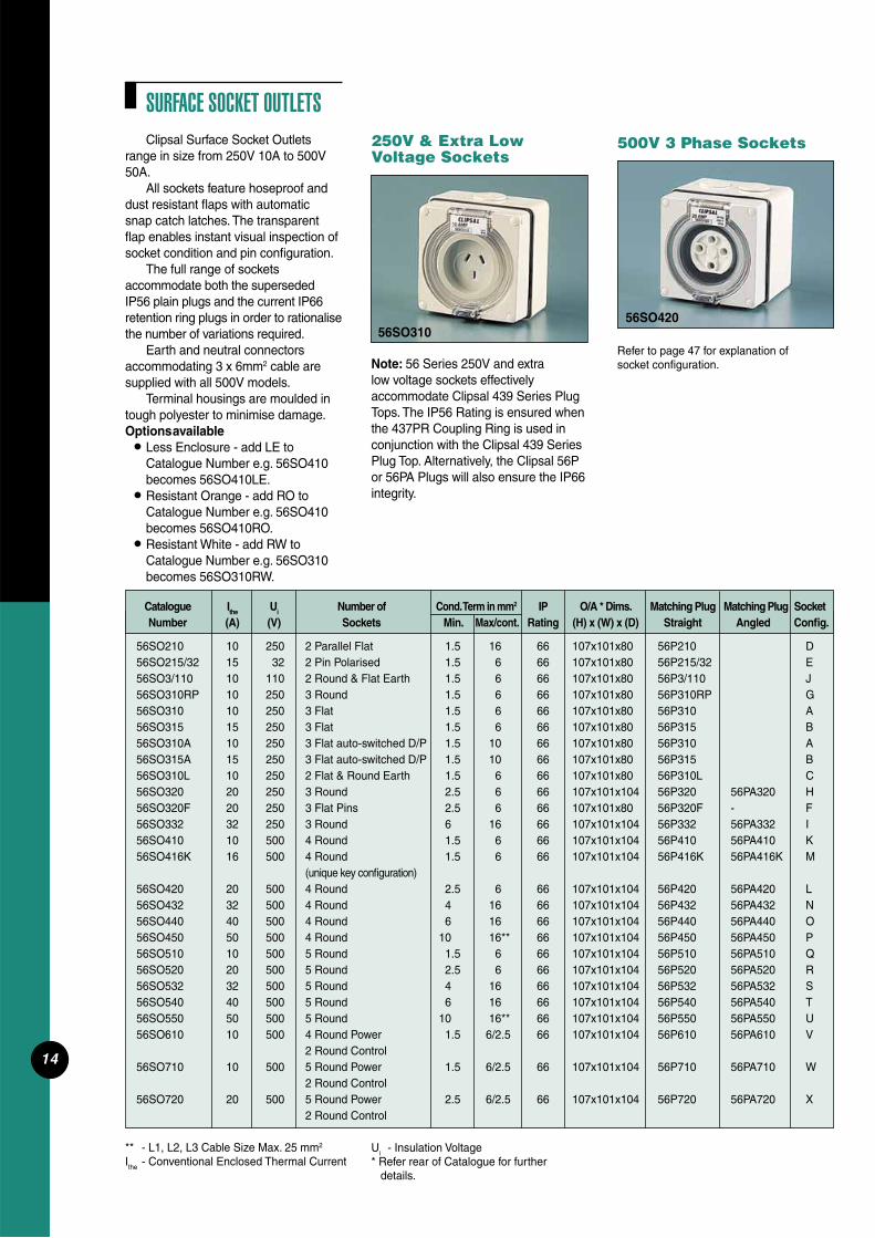
SURFACE SOCKET OUTLETSClipsal Surface Socket Outlets
range in size from 250V 10A to 500V 50A.
All sockets feature hoseproof and dust resistant fl aps with automatic snap catch latches. The transparent fl ap enables instant visual inspection of socket condition and pin confi guration.
The full range of sockets accommodate both the superseded IP56 plain plugs and the current IP66 retention ring plugs in order to rationalise the number of variations required.
Earth and neutral connectors accommodating 3 x 6mm2 cable are supplied with all 500V models.
Terminal housings are moulded in tough polyester to minimise damage.Options available • Less Enclosure - add LE to
Catalogue Number e.g. 56SO410 becomes 56SO410LE.
• Resistant Orange - add RO to Catalogue Number e.g. 56SO410 becomes 56SO410RO.
• Resistant White - add RW to Catalogue Number e.g. 56SO310 becomes 56SO310RW.
Note: 56 Series 250V and extra low voltage sockets effectively accommodate Clipsal 439 Series Plug Tops. The IP56 Rating is ensured when the 437PR Coupling Ring is used in conjunction with the Clipsal 439 Series Plug Top. Alternatively, the Clipsal 56P or 56PA Plugs will also ensure the IP66 integrity.
250V & Extra Low Voltage Sockets
500V 3 Phase Sockets
Catalogue Ithe Ui Number of Cond. Term in mm2 IP O/A * Dims. Matching Plug Matching Plug Socket Number (A) (V) Sockets Min. Max/cont. Rating (H) x (W) x (D) Straight Angled Confi g.
56SO210 10 250 2 Parallel Flat 1.5 16 66 107x101x80 56P210 D56SO215/32 15 32 2 Pin Polarised 1.5 6 66 107x101x80 56P215/32 E56SO3/110 10 110 2 Round & Flat Earth 1.5 6 66 107x101x80 56P3/110 J56SO310RP 10 250 3 Round 1.5 6 66 107x101x80 56P310RP G56SO310 10 250 3 Flat 1.5 6 66 107x101x80 56P310 A56SO315 15 250 3 Flat 1.5 6 66 107x101x80 56P315 B56SO310A 10 250 3 Flat auto-switched D/P 1.5 10 66 107x101x80 56P310 A56SO315A 15 250 3 Flat auto-switched D/P 1.5 10 66 107x101x80 56P315 B56SO310L 10 250 2 Flat & Round Earth 1.5 6 66 107x101x80 56P310L C56SO320 20 250 3 Round 2.5 6 66 107x101x104 56P320 56PA320 H56SO320F 20 250 3 Flat Pins 2.5 6 66 107x101x80 56P320F - F56SO332 32 250 3 Round 6 16 66 107x101x104 56P332 56PA332 I56SO410 10 500 4 Round 1.5 6 66 107x101x104 56P410 56PA410 K56SO416K 16 500 4 Round 1.5 6 66 107x101x104 56P416K 56PA416K M (unique key confi guration)56SO420 20 500 4 Round 2.5 6 66 107x101x104 56P420 56PA420 L56SO432 32 500 4 Round 4 16 66 107x101x104 56P432 56PA432 N56SO440 40 500 4 Round 6 16 66 107x101x104 56P440 56PA440 O56SO450 50 500 4 Round 10 16** 66 107x101x104 56P450 56PA450 P56SO510 10 500 5 Round 1.5 6 66 107x101x104 56P510 56PA510 Q56SO520 20 500 5 Round 2.5 6 66 107x101x104 56P520 56PA520 R56SO532 32 500 5 Round 4 16 66 107x101x104 56P532 56PA532 S56SO540 40 500 5 Round 6 16 66 107x101x104 56P540 56PA540 T56SO550 50 500 5 Round 10 16** 66 107x101x104 56P550 56PA550 U56SO610 10 500 4 Round Power 1.5 6/2.5 66 107x101x104 56P610 56PA610 V 2 Round Control56SO710 10 500 5 Round Power 1.5 6/2.5 66 107x101x104 56P710 56PA710 W 2 Round Control56SO720 20 500 5 Round Power 2.5 6/2.5 66 107x101x104 56P720 56PA720 X 2 Round Control
** - L1, L2, L3 Cable Size Max. 25 mm2
Ithe - Conventional Enclosed Thermal CurrentUi - Insulation Voltage* Refer rear of Catalogue for further details.
56SO42056SO310
Refer to page 47 for explanation of socket confi guration.

15
Spare PartsInternal Socket Housings
A full range of replacement internal socket housings is available for 3 phase 56SO models. They eliminate the need to replace an entire unit if only the internal socket housing is damaged. Socket terminal housings are moulded in durable polyester.
Catalogue Ithe Ui Number of size in mm2 Socket
Number (A) (V) Sockets Min. Max/cont. Confi g.
56SO320G 20 250 3 Round 2.5 6 H 56SO332G 32 250 3 Round 6 16 I 56SO410G 10 500 4 Round 1.5 6 K 56SO416G 16 500 4 Round 1.5 6 M (unique key confi g.)
56SO420G 20 500 4 Round 2.5 6 L 56SO432G 32 500 4 Round 6 16 N 56SO440G 40 500 4 Round 10 16 O 56SO450G 50 500 4 Round 10 16 P 56SO510G 10 500 5 Round 1.5 6 Q 56SO520G 20 500 5 Round 2.5 6 R 56SO532G 32 500 5 Round 6 16 S 56SO540G 40 500 5 Round 10 16 T 56SO550G 50 500 5 Round 10 16 U 56SO610G 10 500 4 Round Power 1.5 6/2.5 V 2 Round Control 56SO710G 10 500 5 Round Power 1.5 6/2.5 W 2 Round Control 56SO720G 20 500 5 Round Power 2.5 6/2.5 X 2 Round Control
56SOXXXG Series
Ithe - Conventional Enclosed Thermal CurrentUi - Insulation Voltage
Refer to page 47 for explanation of socket confi gurations.
Options available • All appliance inlets are available
Less Enclosure - add LE to Catalogue Number e.g. 56AI420 becomes 56AI420LE.
• 56AI310 and 56AI315 versions available in Chemical Resistant Orange e.g. 56AI310 becomes 56AI310RO.
APPLIANCE INLETS56 Series 3 Phase Appliance Inlets
feature a downward facing, angled pin housing which enables extension socket plugs to be neatly connected without bulky right angle entry.
A screwed lock ring is standard on all models to secure extension sockets and appliance connectors, and ensure IP integrity.
All mouldings are impact resistant and UV stabilised.
Note: The IP rating is only achieved on 500V appliance inlets if the screw-on cap (56PC Series) provided is fi tted when not in use.
All 56AI Series Appliance Inlets are compatible with 56CSC Extension Sockets and there is no need for special reverse pin plugs.
Catalogue Ithe Ui Number Conductor Terminal IP Matching Socket O/A* Dims. Number (A) (V) of Pins size in mm2 Rating Extension Confi guration (H) x (W) x (D) Min. Max. Socket Socket
56AI310 10 250 3 Flat 1.5 6 66 56CSC310 A 107x101x38 56AI315 15 250 3 Flat 2.5 6 66 56CSC315 B 107x101x38 56AI320 20 250 3 Round 2.5 6 56 56CSC320 H 204x101x165 56AI332 32 250 3 Round 6 16 56 56CSC332 I 204x101x165 56AI410 10 500 4 Round 1.5 6 56 56CSC410 K 204x101x165 56AI420 20 500 4 Round 2.5 6 56 56CSC420 L 204x101x165 56AI432 32 500 4 Round 6 16 56 56CSC432 N 204x101x165 56AI440 40 500 4 Round 10 16 56 56CSC440 O 204x101x165 56AI450 50 500 4 Round 10 16 56 56CSC450 P 204x101x165 56AI510 10 500 5 Round 1.5 6 56 56CSC510 Q 204x101x165 56AI520 20 500 5 Round 2.5 6 56 56CSC520 R 204x101x165 56AI532 32 500 5 Round 6 16 56 56CSC532 S 204x101x165 56AI540 40 500 5 Round 10 16 56 56CSC540 T 204x101x165 56AI550 50 500 5 Round 10 16 56 56CSC550 U 204x101x165
56AI310 56AI520
Uthe- Conventional Enclosed Thermal CurrentUi
- Rated Insulation VoltageRefer to page 47 for explanation of pin confi gurations.
* Refer rear of Catalogue for further details.
Cond. Term

16
56 Series Surface Switches are available from 250V, 10A to 500V 63A. They incorporate a positive, rotary switch action. ‘ON’ and ‘OFF’ positions are clearly marked and there is provision for two padlocks. Hole diameter is 8mm.
If locking is required in the ‘ON’ position, simply drill a hole where necessary.
To provide easier wiring of our 56 Series Three Pole 63A Switch, a deeper two gang enclosure and centrally mounted option (Cat. No. 56SW363/2), allows additional room for wiring associated with this application.
Earth and neutral connectors accommodating 3 x 6mm2 cables are supplied with all products above 20A. Options available• With Neon - add N to Catalogue No.
e.g. 56SW320 becomes 56SW320N.• Less Enclosure - add LE to
Catalogue Number e.g. 56SW320 becomes 56SW320LE.
• Resistant Orange - add RO to Catalogue Number e.g. 56SW320 becomes 56SW320RO.
• Resistant White - add RW to Catalogue Number e.g. 56SW320 becomes 56SW320RW.
• Chemical Grey - add CG to Catalogue Number e.g. 56SW320 becomes 56SW320CG.
SURFACE SWITCHES
56SW120N
56SW320RO
Ithe - Conventional Enclosed Thermal CurrentUI - Insulation VoltageUe - Operational Voltage
Catalogue No. of Ithe Ui / Ue Ie (A) Utilisation Category M Conductor Terminal IP O/A* Dims. Number Switched (A) (V) Rating size in mm2 Rating (H) x (W) X (D)
Poles AC21A AC22A AC23A Min. Max./cont. 56SW110 1 10 250 10 8 8 M80 1.5 6 66 107x101x80 56SW110HD 1 10 250 10 10 10 M100 6 16 66 107x101x104 56SW110/2~ 1 10 250 10 8 8 M80 1.5 6 66 107x101x80 56SW115 1 15 250 15 8 8 M80 1.5 6 66 107x101x80 56SW115HD 1 15 250 15 15 15 M100 6 16 66 107x101x104 56SW115/2~ 1 15 250 15 8 8 M80 1.5 6 66 107x101x80 56SW110/I~ 1 10 250 10 8 8 M80 1.5 6 66 107x101x80 56SW120 1 20 250 20 20 20 M150 2.5 16 66 107x101x104 56SW132 1 32 250 32 32 28 M180 4 16 66 107x101x104 56SW150 1 50 250 50 50 25 M250 10 25 66 107x101x104 56SW163 1 63 250 63 63 25 M250 16 25 66 107x101x104 56SW220 2 20 500 20 20 20 M150 2.5 16 66 107x101x104 56SW232 2 32 500 32 32 28 M180 4 16 66 107x101x104 56SW250 2 50 500 50 50 25 M220 10 25 66 107x101x104 56SW263 2 63 500 63 63 25 M220 16 25 66 107x101x104 56SW310 3 10 500 10 10 10 M100 1.5 16 66 107x101x104 56SW320 3 20 500 20 20 20 M150 2.5 16 66 107x101x104 56SW332 3 32 500 32 32 28 M180 4 16 66 107x101x104 56SW350 3 50 500 50 50 25 M200 10 25 66 107x101x104 56SW363 3 63 500 63 63 25 M200 16 25 66 107x101x104 56SW363/2 3 63 500 63 63 25 M200 16 25 66 204x101x104 56SW320C 2.5 16/2.5 66 107x101x104 56SW332C 4 16/2.5 66 107x101x104 56SW350C 11 25/2.5 66 107x101x104 56SW420 4 20 440 20 20 20 - 2.5 6 66 107x101x104
Ie - Operational CurrentNote: AC utilisation categories to AS/NZS3947.3.* Refer rear of Catalogue for further details.
~ 56SW110/2 and 56SW115/2 -2 Way switch mechanisms~ 56SW110/I -Intermediate switch mechanism
A S 5 6 S W 3 2 0 + 2 A C H A N G E O V E R A U X . L A T E M A K E E A R L Y B R E A K
A S 5 6 S W 3 3 2 + 2 A C H A N G E O V E R A U X . L AT E M A K E E A R LY B R E A K
A S 5 6 S W 3 5 0 + 2 A C H A N G E O V E R A U X . L AT E M A K E E A R LY B R E A K
For Fluorescent Loads use 56SW110HD OR 56SW115HD instead of 56SW110 or 56SW115.

17
Safety Surface Switches Clipsal's new safety range of isolating
switches ensures isolators are highly visible by using a brightly coloured red switch knob and yellow plate.
The high visibility naturally reduces an individual's response time in the event of an emergency.
Simply add RY to Catalogue Number. e.g. 56SW120 becomes 56SW120RY.
Available in the following Catalogue Numbers:56SW12056SW13256SW32056SW33256SW35056SW363
Refer to previous page for technical information.
56SW120N
250V Single and Twin 2 Way Switches with sliding switch dollies
Options available• Less enclosure - add LE to
Catalogue Number e.g. 56SSW10 becomes 56SSW10LE.
• Resistant Orange - add RO to Catalogue Number e.g. 56SSW10 becomes 56SSW10RO.
56SSW10
Catalogue Description Number of Ithe Ui/Ue M Conductor Terminal IP O/A* Dims. Number Switches (A) (V) Rating size in mm2 Rating (H) x (W) x (D) per Module Min. Max. 56SSW10 Single sliding switch 1 10 250 M80 1.5 6 56 107x101x68 56SSW15 Single sliding switch 1 15 250 M80 1.5 6 56 107x101x68 56SSW10/I Intermediate sliding switch 1 10 250 M100 1.5 6 56 107x101x68 56SSW2/10 Double sliding switch 2 10 250 M80 1.5 6 56 107x101x68 56SSW2/15 Double sliding switch 2 15 250 M80 1.5 6 56 107x101x68
56 Series Single and Twin Sliding Switches are available in 10 and 15A ratings. A single intermediate switch is also available.
Ithe - Conventional Enclosed Thermal CurrentUI - Insulated VoltageUe - Operational Voltage
Note: AC utilisation categories to AS/NZS3947.3. * Refer rear of Catalogue for further details.

18
Options available• Resistant Orange -
add RO to Catalogue Number eg. 56SWH325 becomes 56SWH325RO
• Auxiliary contact - add C for 1 N/C 10A contact to Catalogue Number e.g. 56SWH325 becomes 56SWH325C. Add CO for 1 N/C and 1 N/O 10A contact to Catalogue Number e.g. 56SWH325 becomes 56SWH325CO.
Ithe - Conventional Enclosed Thermal CurrentUI - Insulation VoltageIe - Operational Current
Note: AC utilisation categories to AS/NZS3947.3.Refer to rear of catalogue for further details.
56SWH325
Note: Switch can be fi xed onto a mounting plate as a special.
Clipsal Heavy-Duty Surface Switches come with integral 3 or 4 pole confi gurations, from 25 to 80A ratings. The switch actuator comes standard in safety red/yellow and has 3 padlocking facilities. Hole diameter is 8mm.
The switch is mounted separate to cover in a DIN mounting drop-in cradle which allows quick removal and installation.
The extra deep enclosure allows ample wiring space for easy installation and the switch is suited to motor rating.
Heavy-Duty Surface Switches
CHANGEOVER AND REVERSING SWITCHESDesigned to give full motor control
in a unit that is rated IP66. Clipsal’s Changeover and Reversing Switches are housed within single modules as part of the overall modular concept of the range.
Earth and neutral connectors accommodating 3 x 6mm2 cables are provided with all models.
Option available• Resistant Orange - add RO to
Catalogue Number e.g. 56SW220CO becomes 56SW220CORO.
Clipsal 7 Series Cam Type Switch Mechanisms are used and therefore special confi gurations are available.Contact your Clipsal representative for more information.
Catalogue No. of Ithe Ui / Ue Ie (A) Utilisation Category AC15 Conductor Terminal IP O/A* Dims. Number Switched (A) (V) AC21A AC22A AC23A 240V/415V size in mm2 Rating (H) x (W) x (D) Poles 690V 690V Min. Max.
56SW220CO 2 20 660 20 - 15 8/6 1.5 2 x 4 66 107x101x116 Changeover Switch
56SW420CO 4 20 660 20 - 15 8/6 1.5 2 x 4 66 107x101x116 Changeover Switch
56SW320R 3 20 660 20 - 15 8/6 1.5 2 x 4 66 107x101x116 Reversing Switch
Note: AC utilisation categories to AS/NZS3947.3.Ithe - Conventional Enclosed Thermal CurrentUI - Insulation Voltage
Ue - Operational VoltageIe - Operational Current* Refer rear of Catalogue for further details.
Note - Additional auxiliary contacts are available. Contact your Clipsal representative for details.
Catalogue Number of Ithe Ui Ie (A) Utilisation Category Conductor Terminal IP O/A* Dims. Number Switched (A) (V) size in mm2 Rating (H) x (W) x (D) Poles AC21A AC22A AC23A Min. Max./cont. 56SWH325 3 25 690 25 25 25 1.5 16 56 204x101x172 56SWH340 3 40 690 40 40 25 1.5 16 56 204x101x172 56SWH363 3 63 690 63 63 63 1.5 35 56 204x101x172 56SWH380 3 80 690 80 80 63 1.5 35 56 204x101x172 56SWH425 4 25 690 25 25 25 1.5 25 56 204x101x172 56SWH440 4 40 690 40 40 25 1.5 25 56 204x101x172 56SWH463 4 63 690 63 63 40 1.5 25 56 204x101x172
56SW220C0

19
Options available• Less Enclosure - add LE to
Catalogue Number e.g. 56PB becomes 56PBLE.
PUSH-BUTTON CONTROL STATIONSThis rugged range consists of fi ve
different combinations of stop start control stations.
The stations are ideal in wet, dusty or dirty conditions for controlling motor starters on pumps, saws, compressors, lathes, processors and processing lines.56PB - Start control station.56PBS - Stop control station.56PBS1 - Emergency stop station. This station has a mushroom head with twist reset and red push-button.56PBS2 - Stop station. This station has a mushroom head with twist reset and red push-button (labelled stop only).56/2PB - Combination stop/start control station with momentary operation push-buttons. The red stop button has an extended head and the green start button a fl ush head.56/2PBS1 - Combination stop/start control station with same stop button as the 56PBS1.
56PBS
56/2PB
56PBS1
56PB
56PBS2
56/2PBS1
Catalogue Ithe Ui / Ue Ie(A) Utilisation Category Button Conductor Terminal IP O/A* Dims. Number (A) (V) AC15 DC13 Colour size in mm2 Rating (H) x (W) x (D) 240V 24V Min. Max. 56PB 10 250 6 8 Green 1 4 66 107x101x80 56PBS 10 250 6 8 Red 1 4 66 107x101x86 56PBS1 10 250 6 8 Red 1 4 66 107x101x88 56PBS2 10 250 6 8 Red 1 4 66 107x101x88 56/2PB 10 250 6 8 Red/Green 1 4 66 107x101x86 56/2PBS1 10 250 6 8 Red/Green 1 4 66 107x101x88
Ue - Operational VoltageIe - Operational Current* Refer rear of Catalogue for further details.
Note: AC utilisation categories to AS/NZS3947.5.Ithe - Conventional Enclosed Thermal CurrentUI - Insulated Voltage
• Resistant Orange - add RO to Catalogue Number e.g. 56PBS1 becomes 56PBS1RO.
• Resistant White - add RW to Catalogue Number e.g. 56PBS1 becomes 56PBS1RW.

20
KEY OPERATED SWITCHESonly for peace of mind in high security applications. Locks are selected from the top of the range EFFCO-KABA QUATTRO lock barrels. These locks are available from over 300 locksmiths throughout Australia. Locks are lockable in the ‘off’ position only and the key itself is rotated in order to operate the key mechanism. The switch cover has smooth edges to resist forced actuation.
Options available• Common keys for a number of
switches are available to special order.
• Resistant Orange - add RO to Catalogue Number e.g. 56K1SW120 becomes 56K1SW120RO.
56 Series Key Operated Switches are designed for all key switch applica-tions with the choice of three versions. Earth and neutral connectors accommodating 3 x 6mm2 are supplied with all models.Standard Security - for general applications. From single phase 20A to three phase 50A. These switches are supplied with individual keys.Medium Security - for medium security applications. These switches are fi tted with high quality Lowe and Fletcher locks. The key itself is rotated in order to operate the switch mechanism. These switches are supplied with individual keys. The switch cover has smooth edges to resist forced actuation.High Security - available in kit form
56K2SW320
56K1SW115HS
56K1SW310MS

21
Catalogue No. of I the Ui / Ue Ie (A) Utilisation Category M Cond. Term. size in mm2 IP O/A* Dims.
Number switched poles (A) (V) AC21A AC22A AC23A Rating Min. Max. Rating (H) x (W) x (D)
STANDARD SECURITY SWITCHES
For locking in only the ‘off’ position
56K1SW115 1 15 250 15 10 8 M80 1.5 6 66 107x101x8556K1SW120 1 20 250 20 20 20 M250 2.5 25 66 107x101x10456K1SW132 1 32 250 32 32 25 M250 4 25 66 107x101x10456K1SW150 1 50 250 50 50 25 M250 10 25 66 107x101x10456K1SW220 2 20 500 20 20 20 M220 2.5 25 66 107x101x10456K1SW232 2 32 500 32 32 25 M220 4 25 66 107x101x10456K1SW250 2 50 500 50 50 25 M220 10 25 66 107x101x10456K1SW310 3 10 500 10 10 10 M200 1.5 25 66 107x101x10456K1SW320 3 20 500 20 20 20 M200 2.5 25 66 107x101x10456K1SW332 3 32 500 32 32 25 M200 4 25 66 107x101x10456K1SW350 3 50 500 50 50 25 M200 10 25 66 107x101x104
For locking in both ‘on’ & ‘off’ positions
56K2SW115 1 15 250 15 10 8 M80 1.5 6 66 107x101x8556K2SW120 1 20 250 20 20 20 M250 2.5 25 66 107x101x10456K2SW132 1 32 250 32 32 25 M250 4 25 66 107x101x10456K2SW150 1 50 250 50 50 25 M250 10 25 66 107x101x10456K2SW220 2 20 500 20 20 20 M220 2.5 25 66 107x101x10456K2SW232 2 32 500 32 32 25 M220 4 25 66 107x101x10456K2SW250 2 50 500 50 50 25 M220 10 25 66 107x101x10456K2SW310 3 10 500 10 10 10 M200 1.5 25 66 107x101x10456K2SW320 3 20 500 20 20 20 M200 2.5 25 66 107x101x10456K2SW332 3 32 500 32 32 25 M200 4 25 66 107x101x10456K2SW350 3 50 500 50 50 25 M200 10 25 66 107x101x104
MEDIUM SECURITY SWITCHES
For locking in only the 'off' position
56K1SW115MS 1 15 250 15 10 8 M80 1.5 6 66 107x101x8556K1SW132MS 1 32 250 32 32 20 M250 4 25 66 107x101x10456K1SW310MS 1 10 500 10 10 10 M200 1.5 25 66 107x101x104
For Locking in the 'on' & 'off' Positions
56K2SW115MS 1 15 250 15 10 8 M80 1.5 6 66 107x101x8556K2SW132MS 1 32 250 32 32 20 M250 4 25 66 107x101x10456K2SW310MS 1 10 500 10 10 10 M200 1.5 25 66 107x101x104
HIGH SECURITY SWITCHES
For Locking in the 'off' Position
56K1SW115HS 1 15 250 15 10 8 M80 1.5 6 66 107x101x8556K1SW132HS 1 32 250 32 32 20 M250 4 25 66 107x101x10456K1SW310HS 1 10 500 10 10 10 M200 1.5 25 66 107x101x104
Ithe - Conventional Enclosed Thermal CurrentUi - Insulation VoltageUe - Operational VoltageIe - Operational Current
Note: AC utilisation categories to AS3947.3* Refer rear of Catalogue for further details.

22
TIMER SWITCHES56TC Timer Switches
56 Series TC Synchronised Timers allow time control in IP56 environ-ments. They are available in 24 hour and 7 day confi gurations with minimum switching times as indicated.
All timers are supplied with sliding tabs for easy setting and are fi tted with manual override switches.
Earth and neutral connectors accommodating 3 x 6mm2 cables are supplied.
Two quartz models are available with a 150 hour battery backup.
Note: The 56TC Timer range is not suitable for fl uorescent loads.
Options availableAdd ‘LE’ to Catalogue Numbers
for models Less Enclosure. LE models are suitable for mounting in 56ES1 shallow type enclosures.
•
Catalogue Switching Ithe Ui / Ue Ie (A) Utilisation Category M Battery Running Min. Switch Switch Sliding Cond. Term. size in mm2
Number (A) (V) AC21A AC22A AC23A (Rating) Reserve (Hrs) Time (Min.) Tab Colour Min. Max.
56TC 1 C/O 15 250 15 10 8 M90 N/A 15 Black 2.5 6 56TC7 1 C/O 15 250 15 10 8 M90 N/A 120 Black 2.5 6 56TCB 1 C/O 15 250 15 10 8 M90 **150 15 Violet 2.5 6 56TCB7 1 C/O 15 250 15 10 8 M90 **150 120 Violet 2.5 6
**Nicad rechargeable battery requires 70 hours for full charge.* Refer rear of Catalogue for further details.
Note: AC utilisation categories to AS/NZS3947.3.Ithe - Conventional Enclosed Thermal Current
NEW TIMER SWITCHESOther features are as follows:Holiday Programming
Before going away, a simple holiday program can be set for a period of up to 99 days.
This program will have priority over the normal program and can either operate as set or continually without a preset limit. Program start can be immediate or delayed by up to 6 days.
7 Day Fully Programmable42 Memory Locations
This facility enables up to 21 on/off switching commands to be given at any time during a 7 day period.i.e. Memory No. 1 (ON) Mon, 8.00a.m.
Memory No. 2 (OFF) Mon, 8.25a.m.
Memory No. 3 (ON) Mon, Tue, Wed, 9.00p.m.
Memory No. 4 (OFF) Mon, Tue, Wed, 9.40p.m.
56TCDB Digital Timer Switches
When a timer with pin point precision is required in an IP66 environment, the 56TCDB Digital Timer is the answer.
The digital timer features highly accurate timing and multi-function control with fully programmable push- button facilities.
Earth and neutral connectors accommodating 3 x 6mm2 cables are supplied.
The 56TCDB also incorporates a 150 hour battery running reserve that retains information in the event of a loss of mains power.
Note: The 56TCDB Timer is not suitable to switch fl uorescent loads. The Timer has a stored charge and therefore should not be connected to portable equipment.
56TCDB
Settings can continue through to a maximum of 42 locations.Daylight Saving Switch
Enables summer/winter time changes at the press of a button.150 Hour Battery Running Reserve
Retains program and setting during power blackout.Inbuilt Bypass Switch
This function disengages timing when not required. The Inbuilt Bypass Switch can be set at permanently 'on' or permanently 'off' or 'on' until programmed 'off' or 'off' until programmed 'on'.
Note: 56TCB and 56TCB7 Timers have a stored charge and therefore should not be connected to portable equipment.
56TCB7
UI - Insulated VoltageUe - Operational VoltageIe - Operational Current

23
The 16A mechanism has pressure plate type terminals. The 56SWT216 is ideally suited to run pumping or fi ltering operations or for use with hot water service boosters. Also suitable for fl uorescent loads.
Earth and neutral connectors accommodating 3 x 6mm2 cables are supplied.
Option available• Less enclosure - add LE to
Catalogue Number e.g. 56SWT216 becomes 56SWT216LE.
** Nicad rechargeable battery takes 70 hours to fully charge.* Refer rear of Catalogue for further details.
Ithe - Conventional Enclosed Thermal CurrentUI - Insulated VoltageUe - Operational VoltageIe - Operational Current
Catalogue Switching Ithe Ui / Ue Ie (A) Utilisation Category M Battery Running Minimum Conductor Term. IP O/A* Dims. Number (A) (V) Rating Reserve Switch Time size in mm2 Rating (H) x (W) x (D)
AC21A AC22A AC23A (Hrs) Min. Max.
56TCDB 1 C/O 10A 250 10 10 8 100 **150 hours 1min 2.5 6 66 107x101x100
IP O/A* Dims.
Rating (H) x (W) x (D)
66 107x101x10066 107x101x10066 107x101x10066 107x101x100
56SWT216 Two Hour Process Timer
Clipsal’s 56 Series Two Hour Process Timer is a surface mounting model that features a mechanical timer operated by a rotary switch.
The timer is fully variable with the range of zero to two hours in ten minute increments which can be reset or overridden at any stage.
A single gang module, the unit is double pole 250V 16A a.c. and is supplied as standard with a power on neon.
Catalogue Switching Ithe Ui / Ue Ie (A) Utilisation Category M Switching Conductor Term. IP O/A* Dims. Number (A) (V) Rating Time size in mm2 Rating (H) x (W) X (D) AC21A AC22A AC23A Min. Max. 56SWT216 2 Pole 16 250 16 10 10 120 10 mins. 2.5 4 56 107x101x100 Minimum 120 mins. Maximum
Note: AC utilisation categories to AS/NZS3947.3.
* Refer to rear of catalogue for further details.Ithe - Conventional Enclosed Thermal CurrentUI - Insulated VoltageUe - Operational VoltageIe - Operational Current
56SWT216

24
Sunset switches automatically switch lights on when the ambient light level falls below a predetermined level.
The 56SSR is surface mounting but can be adapted to fl ush mounting by using 56FA Surrounds and Brackets.
The 56SSR allows control of a 10A load current in a two wire confi guration, therefore, eliminating the need for separate neutral at the switch. The 56SSR also incorporates a fully confi gurable timer with a remote-disable option.
When correctly connected to a suitable supply and load, the 56SSR will turn the load on when the ambient light level is below approximately 10 lux. Similarly, the load will be turned off when the light level exceeds approximately 30 lux. Delays of approximately 8 seconds on turn-off and 30 seconds on turn-on
56SSR
are incorporated into the circuit to reject the effects of short term changes in the light levels, which may otherwise turn the load on or off.
The 56SSR is also equipped with a timer circuit which, if enabled, will turn the light off after a preset time delay. The time delay can be from 15 minutes to 15 hours - 45 minutes set in 15 minute increments.
The timer can be disabled by applying neutral potential to the terminal T1 in which case the status of the load is controlled only by the ambient light level. This feature provides a remote timer override function if required.
Since the 56SSR Sunset Switch is a two wire product which does not require any power while the load is turned on, there is one specifi c aspect of its operation well worth noting. When power is applied to the sunset switch for the fi rst time, it will require up to 3.5 minutes to warm up. This behaviour is caused by the time delay required to charge an energy storage element within the unit.
Ithe - Conventional Enclosed Thermal CurrentUI - Insulated VoltageUe - Operational VoltageIe - Operational Current
* Refer rear of Catalogue for further details.Note: Utilisation categories to AS/NZS3947.3
Note: Max. off state leakage current - 8.2 mA 240V a.c. Time accuracy - +/-15%.
Catalogue Ithe Ui / Ue Ic (A) M Temp. Time Conductor Term. IP O/A* Dims. Operating
Number (A) (V) Rating Range Adjust size in mm2 Rating (H) x (W) x (D) Voltage
AC21 AC22 AC23 Min. Max.
56SSR 10A 250 10 10 8 M80 0o to 15 Min. to 1.0 2x4.0 66 101 190- (Min. +40oC 945 Min. 107 265V 40mA) 66 50Hz a.c.
SUNSET SWITCHES PREMIUM
Utilisation Category

25
CONDENSATION DRAINCatalogue Number 56D
Where condensation build up is a problem we offer the 56D.
The 56D is made from chemically resistant nylon and comes complete with a lock nut.
Note: Installation of the 56D will derate the product to IP54.
MOUNTING FEET AND POLE MOUNTING BRACKETS
Catalogue Number 56MFMounting feet and stainless steel
mounting screws (1¼" x 10 gauge) are provided to space 56 Series accessories off walls used in food industries.
The 56MF is designed to be used in conjunction with food industry 280MC
Mounting Channels and 280 Series 25mm Conduit Clips.
Catalogue No. 56PMKA heavy-duty stainless steel pole
mounting kit made of 316 Grade stainless steel. Comes complete with 4¾" and 1¼" size stainless steel mounting screws.
56MF
PADLOCKING CLIPCatalogue Number 56LK
Padlocking Clip to enable the fl ap to be locked closed.
Suits 1/4" Padlock Shank.
56LK
�������������������������
SUNSET SWITCHES ECONOMYA switch that turns lights on at dusk
and off at dawn by itself, how basic is that? For consistent lighting without lifting a fi nger, choose the Clipsal Photo Electric Switch. A 'smart' switch that operates according to the level of sunlight, making it a simple to use, reliable and economical way to save time and energy.
• No capacitor or time programming necessary.
• IP66 Rated for extreme environments.
• Factory set dusk to dawn saves set up time.
• 10A Fluorescent and resistive loads.
• 3 - wire device eliminates the need for capacitor on small inductive loads.
56PEDD3
56PEDD3
Nominal Supply Voltage 220-240 Vac 50 Hz Rated Load 10A Min. Load 0mA Compatible Loads Incandescent and Fluorescent Supply Current 15mA Power Consumption 1W Operating Temperature 0OC - 45OC Turn ON Light Level Approx 10 Lux Turn OFF Light Level Approx 50 Lux
SPECIFICATIONS

26
Catalogue Suits gland Description
Number nut thread
56T20 23mm Suitable for 10-20 amp. 500V plugs. Fits 20mm fl exible hose. 56T25 37mm Suitable for 32-50 amp. 500V plugs. Fits 25mm fl exible hose. 56T32 37mm Suitable for 32-50 amp. 500V plugs. Fits 32mm fl exible hose.
ANGLE & STRAIGHT PLUGSClipsal has a comprehensive range
of straight and angle plugs.All are fi tted with a screwed ring
for securing to socket outlets and to ensure IP66 rating.
Design innovations include a trans-parent centre body section for instant visual checking of connections and an internal cable clamp which grips two ways to prevent cable twisting.
Angled versions ensure a neat cable run when connected to socket outlet.
Options available• When plugs are not in use IP66
rating is maintained by fi tting a 56PC Plug Cap.
• Resistant Orange - add RO to Catalogue Number e.g. 56P410 becomes 56P410RO.
* Note: Refer 56T Series for terminators to connect hose to non standard thread size.
NSW Coalfi eld Certifi cate of ExaminationUi - Insulation VoltageIth - Conventional Free Air Thermal Current
*Refer to rear of catalogue for further details.
Refer to page 47 for explanation of pin confi gurations.
Catalogue Catalogue Ith Ui Number Conductor Term. Cable Nominal IP Pin Gland Nut Number Number (A) (V) of size in mm2 Diameter Rating Confi g. Thread* Straight Angle Pins Min. Max/cont. Min. Max. Straight Angled
56P210 - 10 250 2 Parallel Flat 1.0 2.5 7 12.5 66 D 20mm 56P215/32 - 15 32 2 Polarised 1.5 2.5 7 12.5 66 E 20mm 56P3/110 - 10 110 2 Round & Flat Earth 1.0 2.5 7 12.5 66 J 20mm 56P310RP - 10 250 3 Round 1.0 4 7 12.5 66 G 20mm 56P310 - 10 250 3 Flat 1.0 2.5 7 12.5 66 A 20mm 56P310L - 10 250 2 Flat & Round Earth 1.0 2.5 7 12.5 66 C 20mm 56P320F - 20 250 3 Flat 2.5 2.5 7 12.5 66 F 20mm 56P315 - 15 250 3 Flat 1.5 2.5 7 12.5 66 B 20mm 56P320 56PA320 20 250 3 Round 2.5 4 6 15.7 66 H 25mm 23mm- 56PA332 32 250 3 Round 2.5 16 9.5 28 66 I 37mm56P410 56PA410 10 500 4 Round 2.5 4 6 15.7 66 K 25mm 23mm56P416K 56PA416K 16 500 4 Round 2.5 4 6 15.7 66 M 23mm 23mm (unique key confi guration) 56P420 56PA420 20 500 4 Round 2.5 4 6 15.7 66 L 25mm 23mm56P432 56PA432 32 500 4 Round 2.5 16 9 28 66 N 37mm 37mm56P440 56PA440 40 500 4 Round 2.5 16 9 28 66 O 37mm 37mm56P450 56PA450 50 500 4 Round 2.5 25 9 28 66 P 37mm 37mm56P510 56PA510 10 500 5 Round 2.5 4 6 15.7 66 Q 25mm 23mm56P520 56PA520 20 500 5 Round 2.5 4 6 15.7 66 R 25mm 23mm56P532 56PA532 32 500 5 Round 2.5 16 9 28 66 S 37mm 37mm56P540 56PA540 40 500 5 Round 2.5 16 9 28 66 T 37mm 37mm56P550 56PA550 50 500 5 Round 2.5 25 9 28 66 U 37mm 37mm56P610 56PA610 10 500 6 Round 2.5 4/2.5 6 15.7 66 V 23mm 23mm56P710 56PA710 10 500 7 Round 2.5 4/2.5 6 15.7 66 W 23mm 23mm56P720 56PA720 20 500 7 Round 2.5 4/2.5 6 15.7 66 X 23mm 23mm
56P Series Plugs

27
Plug CapsWhen not in use, Clipsal 56P and
56PA Series Plugs can be additionally protected by utilising our 56PC Series Plug Caps.
When in position, they protect the pins from damage, dirt, grease and water ingress.
The caps are simple to fi t and fully enclose the plug face.
Socket CapsLikewise, to plug caps, Clipsal
single phase CSC Extension Sockets/ Appliance Connectors can be additionally protected by utilising our 56SC2 Socket Cap.
56PC 56PCI 56PC2
Catalogue Phase Suits Overall Dimensions
Number 56PC 3 10A - 20A 69.5mm TPI whitworth 45mm deep 56PCI 3 32A - 50A 69.5mm TPI whitworth 45mm deep 56PC2 1 10A - 20A 59.2mm TPI whitworth 65mm deep 56SC2 1 10A - 15A 59.2mm TPI whitworth 65mm deep
Internal Pin HousingsA full range of replacement pin
housings is available for the three phase straight and angle plugs.
They eliminate the expense of replacing an entire unit if only the pin housing is damaged. Pin housings are moulded in durable polyester.
Catalogue Ith Ui No. of Conductor Term. size in mm2
Number (A) (V) Round Pins Min. Max./Control
56P410G 10 500 4 2.5 4 56P420G 20 500 4 2.5 4 56P510G 10 500 5 2.5 4 56P520G 20 500 5 2.5 4 56PA410G 10 500 4 2.5 4 56PA416KG 16 500 4 2.5 4 56PA420G 20 500 4 2.5 4 56PA432G 32 500 4 2.5 16 56PA440G 40 500 4 2.5 25 56PA450G 50 500 4 2.5 4 56PA510G 10 500 5 2.5 4 56PA520G 20 500 5 2.5 16 56PA532G 32 500 5 2.5 16 56PA540G 40 500 5 2.5 16 56PA550G 50 500 5 2.5 25 56PA610G 10 500 6 2.5 4/2.5 56PA710G 10 500 7 2.5 4/2.5 56PA720G 20 500 7 2.5 4/2.5
Ui - Insulation VoltageIth - Conventional Free Air Current
56PAXXXG Series

28
EXTENSION SOCKETS & APPLIANCE CONNECTORSClipsal’s Three Phase Extension
Socket/Appliance Connector is an important design breakthrough.
Now there is a common unit for both cord extension socket and appli-ance connector applications.
All connectors have impact resist-ant, UV stabilised mouldings.
The IP66 rating can be achieved when extension socket/connectors are used in conjunction with compatible accessories such as 56P Plugs, 56PA Plugs and 56AI Appliance Inlets.
IP66 rated units feature a hose proof cap which maintains the Interna-
56CSC41056CSC532
tional Protection rating when the ac-cessory is not being used.
Note: Cap not provided as standard with single phase extension sockets.Refer 56T Series for terminators to connect hose to non standard gland nut thread.
Options available• 56SC2 Socket Cap to suit single
phase extension sockets.• 56CSC310 and 56CSC315
available in Resistant Orange - add RO to Catalogue Number e.g. 56CSC310 becomes 56CSC310RO.
Catalogue Ith UI No. of Conductor Term. Cable Nominal IP Matching Matching Socket Gland Number (A) (V) Sockets size in mm2 Diameter in mm Rating Plug Plug Confi g. Nut Min. Max. Min. Max. Straight Angle Thread 56CSC310 10 250 3 Flat 1.0 6 6 12.5 66 56P310 56PA310 A 20mm 56CSC315 15 250 3 Flat 1.0 6 6 12.5 66 56P315 56PA315 B 20mm 56CSC320 20 250 3 Round 1.0 6 6 15.7 66 56P320 56PA320 H 23mm 56CSC332 32 250 3 Round 2.5 16 9 28 66 56PA332 I 37mm 56CSC410 10 500 4 Round 1.0 6 6 15.7 66 56P410 56PA410 K 23mm 56CSC420 20 500 4 Round 1.0 6 6 15.7 66 56P420 56PA420 L 23mm 56CSC432 32 500 4 Round 2.5 16 9 28 66 56P432 56PA432 N 37mm 56CSC440 40 500 4 Round 2.5 16 9 28 66 56P440 56PA440 O 37mm 56CSC450 50 500 4 Round 2.5 16 9 28 66 56P450 56PA450 P 37mm 56CSC510 10 500 5 Round 1.0 6 6 15.7 66 56P510 56PA510 Q 23mm 56CSC520 20 500 5 Round 1.0 6 6 15.7 66 56P520 56PA520 R 23mm 56CSC532 32 500 5 Round 2.5 16 9 28 66 56P532 56PA532 S 37mm 56CSC540 40 500 5 Round 2.5 16 9 28 66 56P540 56PA540 T 37mm 56CSC550 50 500 5 Round 2.5 16 9 28 66 56P550 56PA550 U 37mm
Ui - Insulation VoltageIth - Conventional Free Air Current
Refer to page 47 for explanation of socket confi gurations.
PENDANT CONVERSION KITSClipsal 56POK and 56POKI
Pendant Outlet Kits enable the three phase 56CSC Series Industrial Con-nectors to be easily converted to pendant outlets.
There are two models available for connectors 10A - 20A and 32A - 50A, both of which are manufactured from quality stainless steel to last and withstand loads of up to 50kg.
The 56SPOK allows easy conver-sion of the 56C and 56CV Series to pendant outlets.
Catalogue Number Suits 56POK 10A - 20A 56POKI 32A - 50A 56SPOK Switched pendant outlet kit
56SPOK
56POK 56POKI
*Refer to rear of catalogue for further details.

29
PENDANT OUTLETSClipsal 56PO Three Phase Pen-
dant Outlets are a hanging version of our 56CSC Connectors.
All have impact resistant UV stabil-ised mouldings.
56PO532
Catalogue Ith Ui No. of Conductor Term. Cable Nominal IP Matching Matching Socket Gland Number (A) (V) Sockets size in mm2 Diameter in mm Rating Plug Plug Confi g. Nut Min. Max. Min. Max. Straight Angle Thread 56PO410 10 500 4 Round 1.0 6 6 15.7 66 56P410 56PA410 K 23mm 56PO420 20 500 4 Round 1.0 6 6 15.7 66 56P420 56PA420 L 23mm 56PO432 32 500 4 Round 2.5 16 9 28 66 56P432 56PA432 N 37mm 56PO440 40 500 4 Round 2.5 16 9 28 66 56P440 56PA440 O 37mm 56PO450 50 500 4 Round 2.5 16 9 28 66 56P450 56PA450 P 37mm 56PO510 10 500 5 Round 1.0 6 6 15.7 66 56P510 56PA510 Q 37mm 56PO520 20 500 5 Round 1.0 6 6 15.7 66 56P520 56PA520 R 37mm 56PO532 32 500 5 Round 2.5 16 9 28 66 56P532 56PA532 S 37mm 56PO540 40 500 5 Round 2.5 16 9 28 66 56P540 56PA540 T 37mm 56PO550 50 500 5 Round 2.5 16 9 28 66 56P550 56PA550 U 37mm
Ui - Insulation VoltageIth - Conventional Free Air Thermal Current
Catalogue Description
Number
56PEK25 Switched pendant outlet kit, moulded 25mm entry 56PEK32 Switched pendant outlet kit, moulded 32mm entry
SUSPENSION PENDANTENCLOSURE KIT
The suspension enclosure is angled
for easier operation in commercial and
industrial environments.
The 56PEK25 & 56PEK32 Suspension Enclosure Kit is a two module angled enclosure with a large eye for attaching a chain. The angle feature allows for greater ease of operation while suspended. The 56PEK25 has one single 25mm entry and the 56PEK32 has one 32mm entry, both are available in grey (GY), resistive white (RW) and resistive orange (RO).
56SPOK is still available and allows two 56C to be mounted back to back.
56PEK2556PEK32

30
Combination Switched Sockets with RCD Protection
Despite Australia having one of the safest electrical systems in the world, accidents can still occur.
A faulty or poorly maintained ap-pliance, a frayed cord, wet hands or carelessness with power tools are all situations that can lead to tragedy.
To help avoid electrocution in industrial environments, Clipsal has a range of combination switched sockets with inbuilt RCD protection. The RCD works by constantly monitoring and comparing the current fl ow in both the Active and Neutral circuits of an electri-cal installation.
Toroid Mechanism
SPECIAL COMBINATIONS AND MODULES
During normal operation, these Active and Neutral currents are in bal-ance.
However, should any current fl ow to earth, an imbalance is created in these circuits.
If this imbalance is suffi cient (30mA), the RCD will cut the electrical supply in less than 40 milliseconds, perhaps the most important fraction of a second in someone’s life.
Apart from the protection from elec-trocution that an RCD offers, it will also cut off power to expensive electrical equipment in the event of an electrical fault to earth. This protects appliances against costly damage and the installa-tion against fi re resulting from faults of this nature.
Clipsal Combination Switched Sockets with RCD protection enable quick disconnection of power in the case of an emergency and provide mo-tor rated isolation. A neon is standard on all models to indicate that the RCD is protecting the outlet. If the neon is
Catalogue No. of I the Ui/Ue.
Number swit.poles (A) (V)
56SC310RC 1 10 250 56SC315RC 1 15 250 56SC410RC 3 10 500 56SC420RC 3 20 500 56SC432RC 3 32 500 56SC440RC 3 40 500 56SC510RC 3 10 500 56SC520RC 3 20 500 56SC532RC 3 32 500 56SC540RC 3 40 500
Ui - Insulated VoltageUe - Operational VoltageIe - Operational CurrentIthe - Conventional Enclosed Thermal Current
Note: AC utilisation categories to AS/NZS3947.3
* Refer rear of Catalogue for further details.
not illuminated, the RCD has tripped and no power is available from the socket.
The internal phase connections between switches and sockets are factory wired.
The 56RC provides stand alone protection or multiple protection of socket outlets in a modular IP56 Series enclosure.Warning: The RCD used in Clipsal 56 Series modules only protects against shocks from current passing through the body to earth, the cause of the majority of electrocutions. Complete protection under all circumstances is not possible from this or any other device.
Option available• Resistant Orange - add RO to
Catalogue Number e.g. 56C410RC becomes 56C410RCRO.
Live appliance Earthed metal object
Earth
A
N
E
56SC510RC

31
Catalogue No. of Ie Ue No. of Tripping Catalogue Catalogue Overall Socket Number Phases (A) (V) Sockets Sensitivity Number Number Dimensions Confi g. Matching Plug Angled Plug (H) x (W) x (D)
56C310EL2P 1 10 250 2 (3 fl at pins) 30mA 56P310 - 243x294x105 A56C315ELP 1 15 250 1 (3 fl at pins) 30mA 56P315 - 243x195x105 B56SO4ELP15 1 10 250 4 (auto, 3 fl at pins) 30mA 56P310 - 243x294x105 B
SINGLE PHASE RESIDUAL CURRENT DEVICE
Catalogue Number I the Ui / Ue Voltage Parameters Prospective Short Conductor Terminal IP O/A * Dims. Number of Switch (A) (V) Circuit Current size in mm2 Rating (H) x (W) x (D) Poles Min (V) Max. (V) 33kA for 40mS Min. Max/Cont.
56RC 2 20 250 190 260 Unit must be protected 1.5 6 66 107x101x100 by 20A max. MCB.
Refer to page 47 for explanation of pin confi gurations.NSW Coalfi eld Certifi cate of Examination.
Note: Combinations with various pin confi gurations, current ratings and 100mA sensitivity are available to special order.
RCD PROTECTED OUTLETS
Catalogue No. of I the Ui / Ue Number of Conductor Term. IP O/A * Dims. Matching Matching Socket
Number switch (A) (V) Sockets size in mm2 Rating (H) x (W) x (D) Plug Plug Confi g.
poles Min. Max. Straight Angle
56C310RC 2 10 250 3 Flat 2.5 6 56 204x101x100 56P310 - A56C315RC 2 15 250 3 Flat 2.5 6 56 204x101x100 56P315 - B56C410RC 3 10 500 4 Round 1.5 16 56 300x101x135 56P410 56PA410 K56C420RC 3 20 500 4 Round 1.5 16 56 300x101x135 56P420 56PA420 L56C432RC 3 32 500 4 Round 4 16 56 300x101x135 56P432 56PA432 N56C440RC 3 40 500 4 Round 10 16 56 300x101x135 56P440 56PA440 O56C510RC 4 10 500 5 Round 1.5 16 56 300x101x135 56P510 56PA510 Q56C520RC 4 20 500 5 Round 1.5 16 56 300x101x135 56P520 56PA520 R56C532RC 4 32 500 5 Round 4 16 56 300x101x135 56P532 56PA532 S56C540RC 4 40 500 5 Round 10 16 56 300x101x135 56P540 56PA540 T
SWITCHED RCD PROTECTED OUTLETS
Ie (A) Utilisation Category M Number of Cond. Term. size in mm2 IP O/A * Dims. Matching Plug Matching Plug Socket
AC21A AC22A AC23A Rating Sockets Min. Max/Cont. Rating (H) x (W) x (D) Straight Angle Confi g.
10 8 8 M100 3 Flat 2.5 6 56 300x101x100 56P310 - A15 8 8 M100 3 Flat 2.5 6 56 300x101x100 56P315 - B10 10 10 M100 4 Round 1.5 16 56 204x198x135 56P410 56PA410 K20 20 20 M100 4 Round 1.5 16 56 204x198x135 56P420 56PA420 L32 32 20 M100 4 Round 4 16 56 204x198x135 56P432 56PA432 N40 32 20 M100 4 Round 10 16 56 204x198x135 56P440 56PA440 O10 10 10 M100 5 Round 1.5 6 56 204x198x135 56P510 56PA510 Q20 20 20 M100 5 Round 1.5 16 56 204x198x135 56P520 56PA520 R32 32 20 M100 5 Round 4 16 56 204x198x135 56P532 56PA532 S40 40 20 M100 5 Round 10 16 56 204x198x135 56P540 56PA540 T
Portable CombinationSwitched Socketswith RCD
Ruggedly constructed, these portable units feature an easy to carry handle, a hanging facility for builders’ poles and 3 metres of heavy-duty fl ex-ible cord.
56SO4ELP15 56C310EL2P 56C420/ELP
Plug onend of
fl ex
56P31056P315
56P315
Contact your Clipsal offi ce for availability.

32
Combination SwitchedSockets and 24 Hour Timer
Clipsal combinations with a timer have been specially developed for swimming pool applications. Both manual and automatic switching are provided. When manual switching is desired, the time clock is overridden, allowing the unit to be operated as required.
The 24 hour timer has been expressly designed for Australian conditions.
All units are supplied with a Clipsal 439 PVC Plug and Clipsal 437PR Weatherproof Ring for each socket outlet.
Options available56CTC and 56CTC15 are
available less enclosure e.g. 56CTC becomes 56CTCLE.
56CTC2S0 56CTC
Catalogue Ithe Ui / Ue Utilisation Category Ie (A) Transformer M No. of Cond. Term. size in mm2 Timer Number (A) (V) AC21A AC22A AC23A Rating Sockets Min. Max. Type
56CTCT150 10 250 10 8 8 32V 150W M80 Single 3 fl at pins 1.5 8 56TC 56CTCT150/12 10 250 10 8 8 12V 150W M80 Single 3 fl at pins 1.5 8 56TC 56CTCT150/24 10 250 10 8 8 24V 150W M80 Single 3 fl at pins 1.5 8 56TC
•
Catalogue Ithe Ui / Ue No. of M Conductor Term. Timer Ie (A) Utilisation Category Minimum IP O/A* Dims.
Number (A) (V) Sockets Rating size in mm2 Type Time Switch Rating (H) x (W) x (D)
Min. Max. AC21A AC22A AC23A Duration
56CTC 10 250 1 (3 fl at pins) 80 1.5 6 56TC 10 8 8 15 mins. 56 300x101x100 56CTC15 15 250 1 (3 fl at pins) 80 1.5 6 56TC 15 8 8 15 mins. 56 300x101x100 *56CTC2SO 10 250 2 (3 fl at pins) 80 1.5 6 56TC 15 8 8 15 mins. 56 204x198x100 *56CTC2SO15 15 250 2 (3 fl at pins) 80 1.5 6 56TC 15 8 8 15 mins. 56 204x198x100
Ui - Insulation VoltageUe - Operational VoltageIthe - Conventional Enclosed Thermal CurrentIe - Operational Current
Approvals No. S/1/56CTC Series.Please ensure the appropriate 56 Series Plug is used for weatherproof integrity.
*Circuit protection device (HRC Fuse or MCB) to be 16 amp. maximum.* Refer rear of Catalogue for further details.
Combination Switched Socket Timer and Transformer
The Clipsal combination with timer and transformer was also developed for pool applications. It has inbuilt segregation of 250V and low voltage services.
The 24 hour timer has 96 individual settings at 15 minute increments.
Both manual and automatic switching are provided and all relevant internal wiring is supplied and connected. Refer to 56T150 for transformer details.
56CTC150
Ue - Operational VoltageUi - Insulated VoltageIe - Operational CurrentIthe - Conventional Enclosed Thermal Current
Note: AC utilisation categories to AS/NZS3947.3* Refer rear of Catalogue for further details.

33
TRANSFORMERSClipsal transformers are ideal for
swimming pool lighting applications.The 56T150 Series is manufac-
tured to AS3126 and features self re-setting short circuit protection against thermal overload.Note: We recommend that the transformer be installed in a position which provides protection against direct sunlight on exceptionally hot days. This will ensure no nuisance activation of the short circuit protection device. Thermally operated, the device is incorporated in the primary side of the transformer, and will cut out to protect the unit from over-heating.
56T150 56T150/2
Catalogue Rated Voltage Number Conductor Term. size in mm2 O/A* Dims.
Number Input Output Tranformers Min. Max. (H) x (W) x (D)
56T150 250V 32V (150VA) 1 1.5 10 300x101x96 56T150/2 250V 32V (150VA) 2 1.5 10 300x198x96 56T150/12 250V 12V (150VA) 1 1.5 10 300x101x96 56T150/12/2 250V 12V (150VA) 2 1.5 10 300x198x96 56T150/24 250V 24V (150VA) 1 1.5 10 300x101x96 56T150/24/2 250V 24V (150VA) 2 1.5 10 300x198x96
Minimum Time O/A Size IPSwitch Duration (H) x (W) x (D) Rating
15min. 300x198x98 56 15min. 300x198x98 5615min. 300x198x98 56
WALL LIGHTSNeat and discreet, Clipsal wall lights
are the simple way to brighten up all sorts of situations - indoors and out.
They can be either surface mounted or fl ush mounted, making them ideal for garden areas, paths, walkways, subways, etc. - and indoor situations including stairwells and cellars.
Both versions suit single ended fl uorescent lamps (Philips PL5 up to PL7), complete with opal polycarbonate diffuser, and come complete with the following accessories.
56FWL 56WL
56FWL Flush Mounted Wall Light• 56E2 Enclosure.• Lens. Lamp assembly (as for 56WL). Flush-mounting bracket with foam
gasket and sealing screws.
56WL Surface Mounted Wall Light• 56E2 Enclosure.• Lens gasket and sealing screws. Lamp assembly (comprising lamp
holder ballast, terminal block and bracket). Lamps purchased separately.
Catalogue Type IP Rating O/A* Dims.
Number Mounting (H) x (W) x (D)
56WL Surface 66 204x101x91 56FWL Flush 43 254x157x84
Note: IP66 rating is ensured when surface mounting, but when fl ush mounting, IP66 will depend on (1) type/texture of the wall surface and (2) care when mounting to seal all areas where water may enter unit.
* Refer rear of Catalogue for further details.
* Refer rear of Catalogue for further details.

34
56E2/4EL denotes an E2 enclosure complete with 56EL4N Cover and DIN raill to suit 4EL RCDs.
MOUNTING ENCLOSURES(BACK BOXES)
56E Series
Catalogue No. of O/A* Dims. Mounting No. of Cut Out
Number Gangs (L) x (W) x (D) Points Conduit Entries (mm) Provision (mm)
56E1 1 101x101x63 8 2x25, 1x32 1x25/32 56ES1 1 101x101x38 4 1x25, 1x20 1x20/25 56E2 2 198x101x63 8 2x25, 1x32 1x25, 1x32 56ED2 2 198x101x100 8 2x40 1x25, 1x32 56ES2 2 198x101x38 4 1x25, 2x20 2x20/25 56E2/4EL 2 198x101x105 8 2x25, 1x32 1x25, 1x32 56E3 3 294x101x63 16 2x25, 1x32 2x25, 1x32 56E4 4 198x198x63 16 2x25, 2x32 2x25, 1x32, 1x40 56E4VH 4 391x101x63 16 2x25, 1x32 2x25, 1x32, 1x40 56E6 6 294x198x63 24 2x25, 2x32 2x25, 2x32, 2x40 56E8 8 391x198x63 28 2x25, 2x32 4x25, 2x32, 2x40 56E8SB 1 pillar removed 8 391x198x63 28 2x25, 2x32 4x25, 2x32, 2x40 56E9 9 294x294x63 28 3x25, 3x32 4x32, 2x32, 2x40 56E9SB 2 pillars removed 9 294x294x63 28 3x25, 3x32 4x32, 2x32, 2x40 56E16 16 391x391x63 48 2x25, 2x32 6x25, 6x32, 4x40
BRIDGES AND DIVIDERS56 Series Bridges (56B) provide a
continuous fl at surface for socket and switch modules in multigang enclo-sures, thereby ensuring sealing.
Dividers (56DV) are available to segregate services in enclosures.
All Clipsal Mounting Back Boxes are moulded in UV stabilised rigid PVC to facilitate glueing of fi ttings for conduit entry.
Ample conduit and cable entries are provided and there is plenty of wir-ing room for easy installation.
All screwed conduit entries are provided with plugs. The multigang enclosures feature moulded bridges between modules to ensure switches and sockets sit fl ush on a continuous surface. Moulded dividers are also available for multigang boxes to seg-regate services and are standard with 4, 6, 8, 9 and 16 gang enclosures.
Each enclosure has a number of mounting points and 220/10 Sealing Plugs are provided to double insulate mounting screw heads and ensure the IP rating.
Moulded gaskets are supplied with switch and socket modules.
Mounting Accessories• Stainless steel pole mounting
bracket kit to suit 56E2, 56E3 and 56E4VH Modules. Catalogue No. 56PMK.
• Stainless steel mounting feet suit all enclosures. Catalogue Number 56MF.
Options Available• Resistant Orange - add RO to
Catalogue Number e.g. 56E2 becomes 56E2RO. Resistant White - add RW to Catalogue Number e.g. 56E2 becomes 56E2RW. Chemical Grey - add CG to Catalogue Number e.g. 56E2 becomes 56E2CG.
56B
56DV
* Refer rear of Catalogue for further details.
ANTI-CORROSIONENCLOSURE SCREWS
Catalogue No. 56MSThese stainless steel screws are
32mm long M3.5 x 0.8 / 6NC to suit 56E Series Enclosures.
56MS
56E2/4EL

35
MOUNTING ENCLOSURE LIDS (COVERS)
Mounting enclosure lids are moulded in UV stabilised polycarbonate.
All are 28mm high and supplied complete with sealing gasket.Option available• Resistant Orange - add RO to Cat.
No. e.g. 56L1 becomes 56L1RO.• 56L1 available in Chemical
Resistant Grey - add CG to Cat. No. e.g. 56L1 becomes 56CL1CG.
• Resistant White - add RW to Cat. No. e.g. 56L1 becomes 56L1RW.
56L1
56L2
56L3
56L4
Catalogue Number of Dimensions (mm)
Number Gangs A B C D E
56L1 1 95 95 28 84 84 56L2 2 192 95 28 84 181 56L3 3 288 95 28 84 277 56L4 4 192 192 28 181 181
PRE-DRILLED MOUNTINGENCLOSURE LIDSOne gang, 28mm high lids are also
available pre-drilled to accept 22 or 30.5mm diameter IP56 rated push- buttons or indicating lights. Dimensions are identical to the 56L1.
56L3, 56L1
56L1 Series
Catalogue Hole No. of F Number Diameter Holes
56L1/22 22.2mm 1 - 56L1/22/2 22.2mm 2 20 56L1/30 30.5mm 1 - 56L1/30/2 30.5mm 2 20

36
SWITCHGEAR COVERASSEMBLIESThe 56 Series Two Gang Cover
Assemblies are moulded in hi-impact polycarbonate and feature a specially designed mounting bracket which will accommodate the full range of Clipsal circuit breakers, RCDs and combination MCB/RCDs.
Covers suit all 56 Series Enclosures (minimum standard depth 63mm) and are supplied with neon indicators which can be wired from either the line or load side of the switch.
The unique protective membrane versions offer the same level of safety even when the fl ap is opened. A special membrane, incorporated into the units covers MCBs, RCDs and accessories to provide a barrier against dust and water, including wet hands when the fl ap is opened to reset switches.
Option available
• Resistant Orange - add RO to Catalogue Number e.g. 56CB4N becomes 56CB4NRO.
• Resistant White - add RW to Catalogue Number e.g. 56CB4N becomes 56CB4NRW.
• Chemical Grey - add CG to Catalogue Number e.g. 56CB4Nbecomes 56CB4NCG.
• Protective membrane - add M to catalogue number e.g. 56CB4N becomes 56CB4NM.
Catalogue Neon Module No. of Module Protective
Number Voltage Type Poles Width Membrane
56CB4N 240/415 MCB + RCD's 4 4 no 56CB4 - MCB + RCD's 4 4 no 56CB4NM 240/415 MCB + RCD's 4 4 Yes
56CB4NM (+ socket)
56CB4N
56CB4
A protective membrane allows an RCD to be
tested and reset even with wet hands.

37
• The ideal solution for high pressure cleaning en vi ron ments
• Unique and only available from Clipsal
• Designed to suit extreme food prep a ra tion en vi ron ments
• Made to last in our harsh Australian conditions
• Specially developed from extensive fi eld investigations.
56HPG1
2 Gang High Pres sure Gasket suits one two
gang cover
56HPG2/1
56HPG2/2
1 Gang High Pressure Gasket
2 Gang High Pres sure Gasket suits two one
gang covers
56HPG4/34 Gang High Pres sure
Gasket suits one two gang cover and two
one gang covers
56HPG4/44 Gang High Pres sure
Gasket suits four one gang covers
Features
56HPG4/3
56HPG2/2
56HPG2/156HPG1
56HPG4/4
56 HPG SERIES MEETS AND EXCEEDS IP66Protected against jets of water of similar force to heavy seas.
Following extensive fi eld investigations, Clipsal has developed a new high water pressure gasket suited to the rigors of industrial environments.
In industries where hygiene is paramount (dairies, abattoirs), it was found that high-risk areas are most commonly cleaned using a 75°C, 1600psi, 25 l/min, high pressure cleaning gun with chemical cleaner added. The unique 56 Series Clipsal High Pressure Gaskets are specifi cally designed to cope with exposure to this kind of high water pressure blasting and are suited to 56E1, 56E2, and 56E4 enclosures.
56 SERIES HIGHPRESSURE GASKETS
Catalogue Number Description 56HPG1 1 Gang suits 56E1 enclosure 56HPG2/1 2 Gang suits 56E2 encl. and 1x2 gang covers 56HPG2/2 2 Gang suits 56E2 encl. and 2x1 gang covers 56HPG4/3 4 Gang suits 56E4 encl. and 1x1 gang covers 56HPG4/4 4 Gang suits 56E4 encl. and 4x1 gang covers

38
ADAPTABLE ENCLOSURESClipsal Adaptable Enclosures are
supplied complete with gear tray to mount control equipment, contactors, relays, time switches, transformers, etc.
Transparent deep lids (covers), sealing screws and gasket are stan-dard.
Gear trays have eight mounting points for optimum securing. Impact re-sistant and UV stabilised, the backbox and gear tray are moulded in PVC and the lid in polycarbonate.
Option available• Resistant Orange for 56DB2
only - add RO to Catalogue Number e.g. 56DB2 becomes 56DB2RO.
• Other resistant versions avail-able to special order.
• LID ONLY - Add L to cata-logue number. e.g. 56DB2 becomes 56DB2L
Catalogue Number of O/A* Dims. Number of IP Cut Outs
Number Gangs (H) x (W) x (D) Mounting Points Rating (mm)
56XDB1 1 107x101x138 4 IP66 1x25, 1x20 56DB2 2 198x101x140 8 IP66 1x25, 1x32 56DB3 3 294x101x140 12 IP66 2x25, 1x32 56DB4 4 198x198x140 16 IP66 2x25, 1x32, 1x40 56XDB4 4 198x198x180 16 IP66 2x25, 1x32, 1x40 56DB6 6 294x198x140 24 IP66 2x25, 2x32, 2x40 56XDB6 6 294x198x180 24 IP66 2x25, 2x32, 2x40 56DB9 9 294x294x180 28 IP66 4x25, 2x32, 2x40
* Refer rear of Catalogue for further details.
56DB3 56DB6
JUNCTION BOXES56 Series Junction Boxes are
designed for industrial environments. They are supplied complete with Earth and Neutral connectors for up to 3 x 6mm2 cables and sealing gasket.
25mm and 32mm screwed conduit entries and sealing plugs are provided, as are cable entry cut outs in the back.
Options available• Resistant Orange for 56JB1 and
56JB2 only - Add RO to Catalogue Number e.g. 56JB1 becomes 56JB1RO.
• Other resistant versions available to special order.
Catalogue No. of O/A* Dims. IP Cut Outs
Number Gangs (H) x (W) x (D) Rating (mm)
56JB1 1 107x101x90 IP66 1x25/32 56JB2 2 204x101x90 IP66 1x25, 1x32 56JB3 3 300x101x90 IP66 2x25, 1x32 56JB4 4 204x198x90 IP66 2x25, 1x32, 1x40
* Refer rear of Catalogue for further details.
TWO APERTURE ENCLOSURE IP66Apertures suit Clipsal’s popular 30
Series Mechanisms.
Options available
• Other resistant versions available to special order.
Catalogue O/A* Dims. Number (H) x (W) x (D)
56/32 107x101x75
* Refer rear of Catalogue for further details.
56/32

39
Option available• Resistant Orange - add RO to
Catalogue Number e.g. 56FA1 becomes 56FA1RO.
• Resistant White - add RW to Catalogue Number e.g. 56FA1 becomes 56FA1RW.
FLUSH SURROUNDSSurface mounted 56 Series
Sockets, Switches and Combinations can be transformed into fl ush mounting equivalents using the 56FA Surrounds and Brackets. The surrounds can be used on various types of walls to ensure a neat installation.• With a mounting enclosure
(back box) in poured concrete.• With a bracket on brick, brick
veneer or panel walls.The brackets provide the installer
with a practical method of fl ush mounting 56 Series Accessories. Comprehensive installation instructions are supplied with all units.
56FA1, 56FA2, 56FA3 and 56FA4 Flush Surrounds contain a moulded fl ange, foam gasket and stainless steel mounting screws.
56FA1B, 56FA2B, 56FA3B and 56FA4B Flush Surrounds contain a corrosion resistant steel mounting metal bracket.
Catalogue No. of Dimensions
Number Gangs A B C D E
56FA1 1 157 157 13 97 56FA1B 1 141 141 82 56FA2 2 157 254 13 97 194 56FA2B 2 141 242 82 179 56FA3 3 157 350 13 97 281 56FA3B 3 141 338 82 275 56FA4 4 254 254 13 184 184 56FA4B 4 242 242 179 179
Metal BracketsCorrosion Resistant Steel
Dimensional Detail (mm)
Moulded SurroundsUV Stabilised PVC
56FA1 56FA2 56FA1B 56FA2B
COMPUTER SURFACE MODULES
56/01X 56/01/1
Catalogue Description IP O/A* Dims.
Number Rating (W) x (H) x (D)
56/01/1 Suits DB25 66 107x101x73 Connector 56/01X Blank Unit 66 107x101x73
* Refer rear of Catalogue for further details.
Connection of computer and other communication equipment in factory environments is now possible with the Clipsal 56/01/1 and 56/01X.
Both units are single gang 56 Series Modules.
The 56/01/1 enables the fi tting of one DB25 Connector.
The 56/01X is a blank plate which will enable any specifi c customer requested confi guration socket to be fi tted by the installer.Options available• Less enclosure - add LE to
Catalogue Number e.g. 56/01/1 becomes 56/01/1LE.

40
Available in a fully modular design that lets you mix and match from 2 to 16 gangs. With an IP66 Rating they come in High Impact Grey (GY) and Chemical Resistant Orange (RO). You can make your own switchboard by fi xing module devices together.
Features• 4 and13 modules wide to suit DIN
Rail RCDs, MCBs, MCB/RCDs and accesories.
• Deep cover for ample wiring room above and below the DIN rail.
• Solid damage resistant cover.• Cover latches open for easy
maintenance.• Space above MCBs to accept
locking off and padlocking accessories.
• IPA identifi cation drill outs.• Time saving drop in cradle for
easier cable installation on 56SB4. 563/10 Earth and neutral terminator accommodating 3 x 6mm2 cables.
Options Available:• Special 56E8 and 56E9 mounting
enclosures (Backboxes) available with removable pillar to suit 56SB13 add SB to cat no. e.g. 56E8 becomes 56E8SB.
• Less enclosure - add LE to catalogue number e.g. 56SB13 becomes 56SB13LE.
• Resistant Orange for 56SB4 - add RO to catalogue number e.g. 56SB4 becomes 56SB4RO.
56SB13 Features a lockable cover for padlocking up to 7mm diameter hasp. Full size heavy-duty neutral earth bar to accept 2 x 35mm2, 5 x 16mm2 unprotected / 2 x 35mm2, 8 x 16mm2 protected and 2 x 35mm2, 12 x 16mm2 earth. Neutral/Earth bar raised above the base for easy termination.
Catalogue Number Description
56SB4 Consumer switchboard 4 Modules Full DIN with Neutral Bar and Earth Connector (IP66) 56SB13 Consumer switchboard 13 Modules Full DIN with Neutral and Earth Bars. IP66 56SBLK Field fi ttable Key Lock Kit.
56 SERIES DISTRIBUTION BOARD
56SB13

41
56SB4 Features a lockable cover for pad- locking up to 7mm diameter clasp. Full size heavy-duty neutral bar to accept 1 x 35mm2, 4 x 16mm2 and 1 x 35mm2. Neutral bar raised above the base for easy termination.
56SB4
ARMOURED CABLEJUNCTION BOXAvailable in High Impact Grey (GY)
and Chemical Resistant Orange (RO), this 56 Series Junction Box is ideal for installation where cables tee-off to luminaires.
Steel wire armoured cables are internally earthed using a special mounting plate to ensure an IP66 rating. The plate is fi tted with 70mm wide DIN rail for DIN style terminals. Space from the DIN rail to the lid is 58mm.
Each enclosure comes with loose 3 x 563G2 Active Terminals, 1 x 563N10 Neutral Terminal and 1 x 563E10 Earth Terminal (suitable for 3 x 6mm2). The box also comes with 3 x 20mm screwed conduit entries complete with blanking plugs.
Catalogue No. of O/A* Dims. Cut Outs
Number Gangs (H) x (W) x (D) (mm)
56JB1SWA 1 107 x 101 x 90 1 x 25/32
56JB1SWA
56 SERIES DISTRIBUTION BOARD

42
Catalogue Motor Starter c/w Reset
Number Rating Isolator Only
56YD9 7.5 56YD9SW 56YD9R 56YD12 11 56YD12SW 56YD12R 56YD16 15 56YD16SW 56YD16R 56YD20 18 56YD20SW 56YD20R 56YD26 22 56YD26SW 56YD26R 56YD33 30 56YD33SW 56YD33R
56YD RANGE
MOTOR STARTERSThe rugged reliability and modular
construction of Clipsal 56 Series Industrial Switchgear, when combined with the cutting edge technology of the Clipsal 6 Series range of Contactors and Overload Relays, will give you the most exciting breakthrough in motor control technology.
56 Series Motor Starters offer unequalled levels of design fl exibility together with superior on-the-job performance.
Features• Modular fl exibility. Starters can be
coupled with almost any number of 56 Series Modules in one enclosure.
• Ease of wiring.• UV stabilised for proven outdoor
performance.• Chemical Resistant Orange (RO)
enclosures are available for environ- mentally aggressive locations.
• Hoseproof and dustproof to IP66.
• Heavy-duty impact resistant enclosure.
• Customised units can be ordered to meet individual customer requirements.
Models available• Direct-On-Line (DOL) Starters• Reversing (ROL) Starters • Enclosed Star-Delta Starters
Refer to separate catalogue on 56 Series Motor Starters for further details.
Two Contactor Motor One Contactor with
Version Rating Fwd/Off/Rev Switch
56ROL9 4 56ROL9SW 56ROL12 5.5 56ROL12SW 56ROL16 7.5 56ROL16SW 56ROL22 11 56ROL22SW 56ROL32 15 56ROL32SW 56ROL38 18.5 56ROL38SW
56 ROL RANGE
Catalogue Motor C/W Reset
Number Rating Isolator Only
56DOL9 4 56DOL9SW 56DOL9R 56DOL12 5.5 56DOL12SW 56DOL12R 56DOL16 7.5 56DOL16SW 56DOL16R 56DOL22 11 56DOL22SW 56DOL22R 56DOL32 15 56DOL32SW 56DOL32R 56DOL38 18.5 56DOL38SW 56DOL38R
56 DOL RANGE

43
M56 SERIES
M56E1
Mounting Enclosures(Back box)
Fully interchangeable with the 56 Series. Application - can be used with plastic range to provide Earthing continuity when using metal conduit or steel wire armoured cables.
M56E1 = 2 x 25 Dia. and 1 x 32 Dia. conduit entries available.
M56E1U = no entries for drilling by customer.
Other entries are available as specials.
Lids OnlyM56L1 Lids are available complete
with sealing gasket.
Catalogue Number of Ithe Ui/Ue
Number Switched Poles (A) (V)
M56SW110HD 1 10 250 M56SW120 1 20 250 M56SW132 1 32 250 M56SW150 1 50 250 M56SW163 1 63 250 M56SW220 2 20 500 M56SW232 2 32 500 M56SW250 2 50 500 M56SW263 2 63 500 M56SW310 3 10 500 M56SW320 3 20 500 M56SW332 3 32 500 M56SW350A 3 50 500 M56SW350B 3 50 500 M56SW363A 3 63 500 M56SW363B 3 63 500 M56SW420 4 20 500 M56SW432 4 32 500
M56JB1 M56PBS1 M56SW320
Cast Metal SwitchesCrafted in cast aluminium and
interchangeable with the 56 Series, the M56 Series is the solution for industry that requires switches that will withstand high temperatures, aggres-sive environments and offer increased impact resistance.
The simply styled modules have an IP66 rating. Dirt and other foreign objects cannot enter reccesses and crevices, making this series ideal for environments such as food processing plants.
The switch has a rotary action that is easy to operate, even if wear-ing gloves. The 'ON' and 'OFF' switch positions are clearly marked as are the current ratings.
Less Enclosure (LE) versions are also available, which are fully compat-ible with the 56 Series Enclosures.
Note: Refer to separate M56 Series catalogue for further details.
Junction BoxesDesigned for the heavy industrial
environments the M56JB1 has 2 x 25 Dia. and 1 x 32 Dia. entries and comes complete with Earth and Neutral connectors for up to 3 x 6mm sq. mm. cables and sealing gasket.
Surface Switches
Ui - Insulated VoltageUe - Operational VoltageIthe - Conventional Enclosed Thermal Current
Catalogue Entry Number Size
M56CP20 20mm M56CP25 25mm M56CP32 32mm M56CP40 40mm
Metal Conduit Plugs
Catalogue Ithe Ui / Ue
Number (A) (V)
M56PBS1 10 240
Push-buttonsThis rugged range rated at IP66
consists initially of one confi guration only. This station has a mushroom head with twist reset and red push-button.
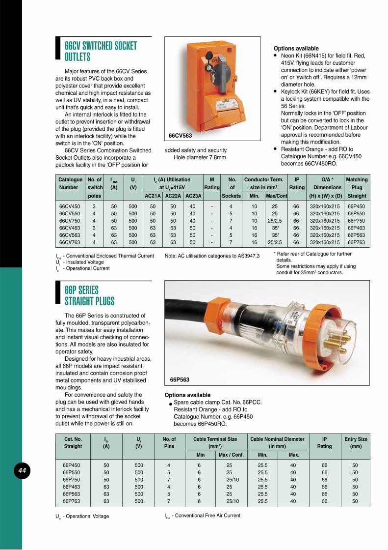
44
66CV SWITCHED SOCKET OUTLETSMajor features of the 66CV Series
are its robust PVC back box and polyester cover that provide excellent chemical and high impact resistance as well as UV stability, in a neat, compact unit that's quick and easy to install.
An internal interlock is fi tted to the outlet to prevent insertion or withdrawal of the plug (provided the plug is fi tted with an interlock facility) while the switch is in the 'ON' position.
66CV Series Combination Switched Socket Outlets also incorporate a padlock facility in the 'OFF' position for
Cat. No. Ith Ui No. of Cable Terminal Size Cable Nominal Diameter IP Entry Size Straight (A) (V) Pins (mm2) (in mm) Rating (mm)
Min Max / Cont. Min. Max.
66P450 50 500 4 6 25 25.5 40 66 5066P550 50 500 5 6 25 25.5 40 66 5066P750 50 500 7 6 25/10 25.5 40 66 5066P463 63 500 4 6 25 25.5 40 66 5066P563 63 500 5 6 25 25.5 40 66 5066P763 63 500 7 6 25/10 25.5 40 66 50
Ue - Operational Voltage
added safety and security.Hole diameter 7.8mm.
66CV563
Options available• Neon Kit (66N415) for fi eld fi t. Red,
415V, fl ying leads for customer connection to indicate either ‘power on’ or ‘switch off’. Requires a 12mm diameter hole.
• Keylock Kit (66KEY) for fi eld fi t. Uses a locking system compatible with the 56 Series.
Normally locks in the ‘OFF’ position but can be converted to lock in the ‘ON’ position. Department of Labour approval is recommended before making this modifi cation.
• Resistant Orange - add RO to Catalogue Number e.g. 66CV450 becomes 66CV450RO.
Note: AC utilisation categories to AS3947.3
Catalogue No. of I the Ui Ie (A) Utilisation M No. Conductor Term. IP O/A * Matching
Number switch (A) (V) at Ue=415V Rating of size in mm2 Rating Dimensions Plug
poles AC21A AC22A AC23A Sockets Min. Max/Cont (H) x (W) x (D) Straight
66CV450 3 50 500 50 50 40 - 4 10 25 66 320x160x215 66P45066CV550 4 50 500 50 50 40 - 5 10 25 66 320x160x215 66P55066CV750 4 50 500 50 50 40 - 7 10 25/2.5 66 320x160x215 66P75066CV463 3 63 500 63 63 50 - 4 16 35* 66 320x160x215 66P46366CV563 4 63 500 63 63 50 - 5 16 35* 66 320x160x215 66P56366CV763 4 63 500 63 63 50 - 7 16 25/2.5 66 320x160x215 66P763
Ithe - Conventional Enclosed Thermal CurrentUi - Insulated VoltageIe - Operational Current
* Refer rear of Catalogue for further details. Some restrictions may apply if using conduit for 35mm2 conductors.
66P SERIES STRAIGHT PLUGSThe 66P Series is constructed of
fully moulded, transparent polycarbon-ate. This makes for easy installation and instant visual checking of connec-tions. All models are also insulated for operator safety.
Designed for heavy industrial areas, all 66P models are impact resistant, insulated and contain corrosion proof metal components and UV stabilised mouldings.
For convenience and safety the plug can be used with gloved hands and has a mechanical interlock facility to prevent withdrawal of the socket outlet while the power is still on.
Ithe - Conventional Free Air Current
Options availableSpare cable clamp Cat. No. 66PCC.Resistant Orange - add RO to
Catalogue Number. e.g. 66P450 becomes 66P450RO.
•
66P563
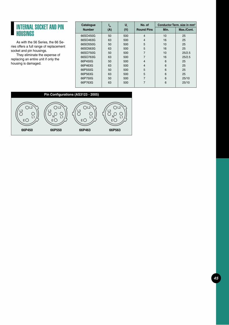
45
INTERNAL SOCKET AND PIN HOUSINGSAs with the 56 Series, the 66 Se-
ries offers a full range of replacement socket and pin housings.
They eliminate the expense of replacing an entire unit if only the housing is damaged.
Catalogue Ith Ui No. of Conductor Term. size in mm2
Number (A) (V) Round Pins Min. Max./Cont.
66SO450G 50 500 4 10 25 66SO463G 63 500 4 16 25 66SO550G 50 500 5 10 25 66SO563G 63 500 5 16 25 66SO750G 50 500 7 10 25/2.5 66SO763G 63 500 7 16 25/2.5 66P450G 50 500 4 6 25 66P463G 63 500 4 6 25 66P550G 50 500 5 6 25 66P563G 63 500 5 6 25 66P750G 50 500 7 6 25/10 66P763G 63 500 7 6 25/10
Pin Confi gurations (AS3123 - 2005)
L2L3
L1NE
L2L3
L1NE
L2L3
L1E
L2L3
L1E
66P450 66P550 66P463 66P563

46
56AI54056AI550
500V Three Phase Appliance Connectors56CSC41056CSC42056CSC43256CSC44056CSC45056CSC51056CSC52056CSC53256CSC54056CSC550
Department of Industrial RelationsCoal Mines Regulation Act 1982
Rotary Switches (Single, Double and Triple Pole)56SW12056SW13256SW15056SW22056SW25056SW32056SW33256SW350
500V Three Phase Sockets56SO53256SO55056SO54056SO61056SO71056SO720
500V Three Phase Angle Plugs56PA41056PA51056PA52056PA53256PA54056PA55056PA61056PA71056PA720
56CV332
With Interlock56CVI32056CVI332
500V Three Phase Plugs
Angle56PA41056PA42056PA43256PA44056PA45056PA51056PA52056PA53256PA54056PA55056PA61056PA71056PA720
Straight56P41056P42056P43256P44056P45056P45056P51056P52056P53256P54056P55056P61056P71056P720
250V a.c. and Low Voltage Plugs56P21056P215/3256P3/11056P31056P310L563P10RP56P31356P32056P320F56P33256PA32056PA332
Appliance Inlets56AI31056AI31556AI41056AI42056AI43256AI44056AI45056AI51056AI52056AI532
56SW340C56SW350C56SW363C
250V Two-way Switches (Single and Twin with Sliding Switch Dollies)56SSW1056SSW1556SSW2/1056SSW2/15
500V Three Phase Combination Switched Sockets56C41056C42056C43256C44056C45056C51056C52056C53256C54056C55056C61056C71056C72056CV41056CV42056CV43256CV44056CV45056CV51056CV52056CV53256CV54056CV55056CV61056CV71056CV720
250V and Low Voltage Switched Sockets (Single and Double Pole Combination)
2 Module56C21056C215/3256C3/11056C31056C310D56C310L56C310RP56C31356C31556C315D56C32056C332
With Standard One Piece Cover56CV31056CV31556CV320
LLOYD’S REGISTER OF SHIPPING APPROVALS FOR 56 SERIES SWITCHGEAR
500V Three Phase Sockets56SO41056SO42056SO43256SO44056SO45056SO51056SO52056SO53256SO54056SO55056SO61056SO71056SO720
250V and Extra Low Voltage Sockets56SO21056SO215/3256SO3/11056SO31056SO310L56SO310RP56SO31356SO31556SO32056SO320F56SO332
Rotary Switches (Single, Double and Triple Pole)56SW11056SW110/256SW11556SW115/256SW12056SW13256SW14056SW15056SW16356SW22056SW23256SW24056SW25056SW26356SW31056SW32056SW33256SW34056SW34056SW35056SW36356SW310C56SW320C56SW332C
56 Series accessories comply with the relevant parts of the following standards:AS/NZS3123 - Approval and test specifi cations - plugs, socket outlets and couplers for general industrial application.AS/NZS3133 - Approval and test specifi cations - air break switches.

47
PLUGCONFIGURATIONS
2 & 3 Pin10A 250V
A
15A 250V
B
10A 250V
C
10A 250V
D
15A 32VPolarisedE
20A 250V
F
10A 250V
G
20A 250V
H
32A 250V
I
10A 110V
J
4 Pin10A 500V
K
20A 500V
L
15A 500V(unique)M
32A 500V
N
40A 500V
O
50A 500V
P
5 Pin10A 500V
Q
20A 500V
R
32A 500V
S
40A 500V
T
50A 500V
U
6 Pin10A 500V
V
7 Pin10A 500V
W
20A 500V
X
15A 500V(unique)M
32A 500V
N
40A 500V
O
50A 500V
P
5 Pin10A 500V
Q
20A 500V
R
32A 500V
S
40A 500V
T
50A 500V
U
6 Pin10A 500V
V
7 Pin10A 500V
W
20A 500V
X
SOCKET CONFIGURATIONS
2 & 3 Pin10A 250V
A
15A 250V
B
10A 250V
C
10A 250V
D
15A 32VPolarisedE
20A 250V
F
10A 250V
G
20A 250V
H
32A 250V
I
10A 110V
J
4 Pin10A 500V
K
20A 500V
L

48
101
REAR MECHANISMS
FRONT COMPLETEFRONT MOUNTING ENCLOSURE
FRONT MOUNTING ENCLOSURE SIDE COMPLETE FRONT COMPLETE
56C210
N A
ENTRIES
CUT-OUTS
CONDUIT2 x M25
ENTRYCONDUIT1 x M25
CUT-OUT
CUT-OUT
1 x M32
1 x M25
L
C1L 1L
REAR MECHANISMS REAR MECHANISMS
SIDE COMPLETE
56C310
L
AN
E
2 x M20CONDUITENTRIES
1 x M25CONDUITENTRY
2 x M20/25
56C310L
56C310RP
56C315
56C3/110
56C215/32
204
101
198
30 SERIES MECHSWITCH IS
50
56C315HD56C310HD
AA
74
140
50
50
40
18
38
80
18
C
40
50
140
75
5555
165
63
30
31
104
43
198 204
E L
REAR MECHANISMS
A A
IS PRESSURE PLATE TYPECONDUCTOR TERMINATION
ARE NOT IDENTIFIEDSWITCH TERMINALS
BACKWIREDSWITCH IS
N N
E
N
56C310D56C315D
L
AA
C1
REAR MECHANISMS
L
C
L 1
10
17
TECHNICAL DRAWINGS
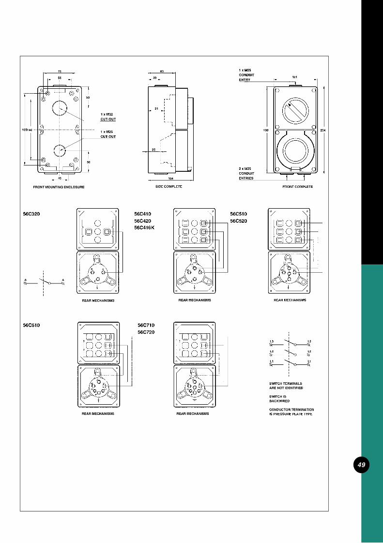
49

50
56C440 56C540
REAR MECHANISMS REAR MECHANISMS REAR MECHANISMS IS PRESSURE PLATE TYPECONDUCTOR TERMINATION
ARE NOT IDENTIFIEDSWITCH TERMINALS
BACKWIREDSWITCH IS
101
FRONT MOUNTING ENCLOSURE SIDE COMPLETE FRONT COMPLETE
ENTRIESCONDUIT2 x M25
ENTRYCONDUIT1 x M32
CUT-OUT
CUT-OUT
1 x M32
1 x M25
50
56C332
AA
40
50
140
75
5555
165
63
31
104
198 204
56C53256C54056C440
56C432
E
L2
E
L3 L1
L2
E
L3 L1
N
N A
L3 L3
L2L2
L1L1
22
21
30
REAR MECHANISMS
104
SIDE COMPLETE
L3 L1
E
L2
56C450
30
21
22
63
REAR MECHANISMS
L3
L2
L1
FRONT COMPLETE
101
56C550
CONDUITENTRIES
2 x M25
ENTRY
198
CONDUIT1 x M32
L2
L1
L3
204
FRONT MOUNTING ENCLOSURE
40
165140
5555
75
CUT-OUT
50
1 x M25
1 x M32CUT-OUT
50
21
L3
E
L1
L2
IS PLAIN SCREW TYPECONDUCTOR TERMINATION
ARE NOT IDENTIFIEDSWITCH TERMINALS
BACKWIREDSWITCH IS
N
E
L2
L3
E
L1
L2
L3
E
L1

51
FRONT COMPLETEFRONT MOUNTING ENCLOSURE
CUT-OUTS
SIDE COMPLETE
2 x M20CONDUITENTRIES
1 x M25CONDUITENTRY
2 x M20/25
56CV310
204
101
198
30 SERIES MECHSWITCH IS
74
140
50
50
40
18
38
80
18
C1
10
10
1L
C
N E A
C
REAR MECHANISMS
56CV315
30
FRONT MOUNTING ENCLOSURE
A
56CV310HD56CV315HD
165 140
REAR MECHANISMS
A E
N
L
A
40
50
5555
50
CUT-OUT
CUT-OUT
1 x M25
1 x M32
75CONDUIT
SWITCH ISBACKWIRED
SWITCH TERMINALSARE NOT IDENTIFIED
CONDUCTOR TERMINATIONIS PRESSURE PLATE TYPE
SIDE COMPLETE
43
104
31
2 x M25CONDUITENTRIES
ENTRY101
FRONT COMPLETE
198 204
63 1 x M25

52

53
104
SIDE COMPLETE
L3 L1
E
L2
30
22
63
L3
L2
L1
FRONT COMPLETE
CONDUITENTRIES
2 x M25
ENTRY
198
CONDUIT1 x M32
L2
L1
L3
204
FRONT MOUNTING ENCLOSURE
40
165 140
5555
75
CUT-OUT
50
1 x M25
1 x M32CUT-OUT
50
21
L3
E
L1
L2
IS PLAIN SCREW TYPECONDUCTOR TERMINATION
ARE NOT IDENTIFIEDSWITCH TERMINALS
BACKWIREDSWITCH IS
N
REAR MECHANISMS
56CV450
REAR MECHANISMS
56CV550
198
1 x M25
1 x M32
CUT-OUT
CUT-OUT
IS PRESSURE PLATE TYPECONDUCTOR TERMINATION
ARE NOT IDENTIFIEDSWITCH TERMINALS
BACKWIREDSWITCH IS
L1
L2
L3
L1
L2
L3
FRONT MOUNTING ENCLOSURE
40
50
140165
5555
75
50
REAR MECHANISMS
56CV440
L2
L3
E
L1
REAR MECHANISMS
56CV540
L3 L1L3 L1
EE
N
L2L2
SIDE COMPLETE
56CV432
30
21
104
31
22
63
56CV532
CONDUITENTRIES
2 x M25
FRONT COMPLETE
198
1 x M32CONDUITENTRY
204
101
21
56CV440 56CV540

54
56RC
FRONT COMPLETEFRONT MOUNTING ENCLOSURE
CUT-OUT
2 x M25CONDUITENTRIES
1 x M25/32
REAR MECHANISMS
1 x M25CONDUITENTRY
101
107101
SIDE COMPLETE
E
NA
35
74
5555
40
50
70 45
100
63
30
43
SIDE COMPLETEFRONT MOUNTING ENCLOSURE
56C315RC56C310RC
140165
REAR MECHANISMS
1 x M32
1 x M25
CUT-OUT
CUT-OUT
40
50
5555
75
50
30
198
100
63
2 x M25
ENTRIESCONDUIT
1 x M25CONDUITENTRY
101
FRONT COMPLETE
204
35
A N
CONDUCTORS
LINE
BUTTON
TEST
A
N
A
H
N
E
POWERAVAILABLEL.E.D.
CONDUCTORS
LOAD
CONDUCTORS
LINE
TEST
BUTTON
A
N
POWER
L.E.D.AVAILABLE
H
CONDUCTORS
LOAD
A
N
AA N
LINE
LOAD
AA N
E
N
L
A

55
FRONT COMPLETE
2 M25 CONDUIT ENTRIES
295
1 x M32CONDUIT ENTRY
300
10263
30
30
110
SIDE COMPLETE
15 CLEARANCE

56
FRONT COMPLETE
2 M25 CONDUIT ENTRIES
295
1 x M32CONDUIT ENTRY
300
10263
30
30
110
SIDE COMPLETE
15 CLEARANCE

57
E
REAR MECHANISMS
N
L
A
FRONT MOUNTING ENCLOSURE
235260 70 45
40
50
CUT-OUT1 x M25
1 x M32CUT-OUT
55
50
75
CUT-OUT1 x M25
SIDE COMPLETE FRONT COMPLETE
300
30
100
2 x M25CONDUIT
ENTRIES
30
63
ENTRY
CONDUITCONDUIT
294
101
1 x M25
56SC310RC
43
56SC315RC
A N
BUTTON
CONDUCTORS
LINE
TEST
A
N
35
CONDUCTORSE
N
A
LOAD
AVAILABLEPOWER
H
L.E.D.
31
NAA
LINE

58
63
30
30
110
SIDE COMPLETE
15 CLEARANCE
2 x M32CONDUIT ENTRIES
FRONT COMPLETE
2 M25 CONDUIT ENTRIES
204
198
198
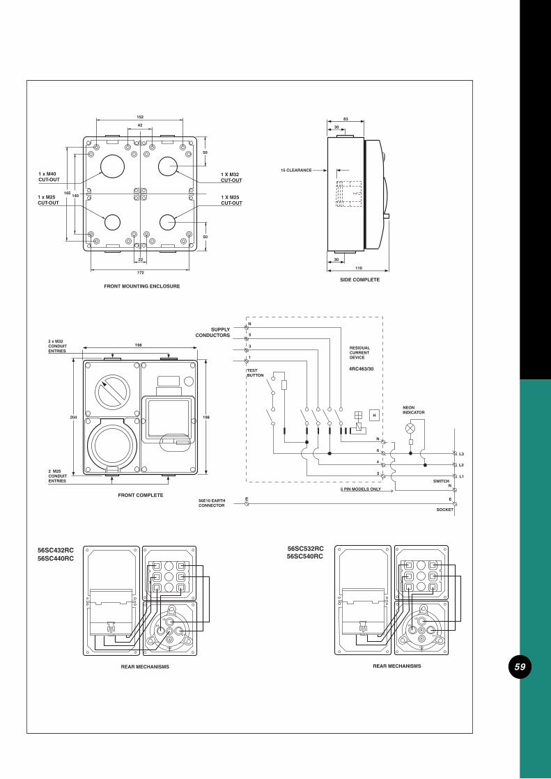
59
63
30
30
110
SIDE COMPLETE
15 CLEARANCE
2 x M32CONDUIT ENTRIES
FRONT COMPLETE
2 M25 CONDUIT ENTRIES
204
198
198
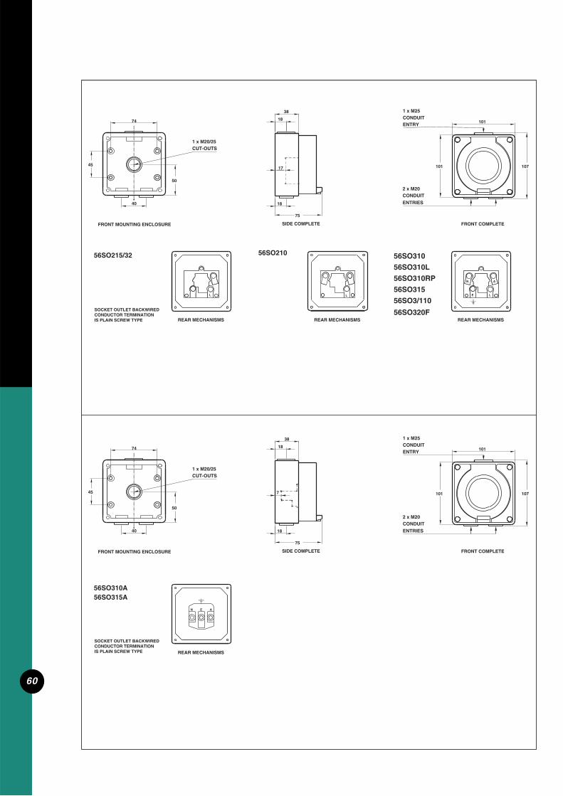
60
56SO215/32
FRONT COMPLETEFRONT MOUNTING ENCLOSURE
56SO210
CUT-OUTS
L
REAR MECHANISMS REAR MECHANISMS
SIDE COMPLETE
56SO310
L
AN
E
2 x M20CONDUITENTRIES
1 x M20/25
56SO310L
56SO310RP
56SO315
56SO3/110
50
40 18
REAR MECHANISMS
L
17
1 x M25CONDUITENTRY
10174
45
75
38
18
107101
SIDE COMPLETEFRONT MOUNTING ENCLOSURE
45
40
CUT-OUTS1 x M20/25
50
18
38
1874
101
75
ENTRY
1 x M25CONDUIT
FRONT COMPLETE
101
107
56SO310A
REAR MECHANISMS
N E A
7
CONDUITENTRIES
2 x M20
56SO315A
SOCKET OUTLET BACKWIREDCONDUCTOR TERMINATIONIS PLAIN SCREW TYPE
CONDUCTOR TERMINATIONSOCKET OUTLET BACKWIRED
IS PLAIN SCREW TYPE
56SO320F
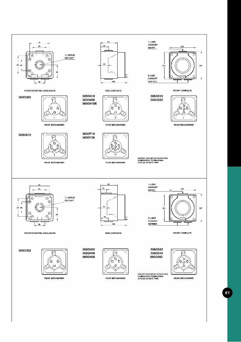
61

62
AA
IS PRESSURE PLATE TYPECONDUCTOR TERMINATION
ARE NOT IDENTIFIEDSWITCH TERMINALS
BACKWIREDSWITCH IS
C
L 1
56SW110
FRONT COMPLETEFRONT MOUNTING ENCLOSURE
56SW110/2
CUT-OUTS
REAR MECHANISMS REAR MECHANISMS
SIDE COMPLETE
2 x M20CONDUITENTRIES
1 x M20/25
50
40 18
REAR MECHANISMS
1 x M25CONDUITENTRY
10174
45
80
38
18
107101
40
5555
74
FRONT MOUNTING ENCLOSURE
56SW110HD
4570
REAR MECHANISMS
56SW220
1 x M25/32CUT-OUT
50
56SW320
101
REAR MECHANISMS
SIDE COMPLETE
104 ENTRIESCONDUIT2 x M25
63
ENTRYCONDUIT1 x M25
REAR MECHANISMS
FRONT COMPLETE
101
107
30
C
L
1
3
4
12 2
56SW115 56SW115/256SW110/I
31
10
SWITCH IS
1 C
2
1
C2
1
4
3
30 SERIES MECH
L3 L3
L2L2
L1L1
56SW12056SW115HD
L1L1
L2L2
56SW310

63
AA
IS PRESSURE PLATE TYPECONDUCTOR TERMINATION
ARE NOT IDENTIFIEDSWITCH TERMINALS
BACKWIREDSWITCH IS
40
5555
74
FRONT MOUNTING ENCLOSURE
56SW132
4570
REAR MECHANISMS
56SW232
1 x M25/32CUT-OUT
50
56SW332
101
REAR MECHANISMS
SIDE COMPLETE
104 ENTRIESCONDUIT2 x M25
63
ENTRYCONDUIT1 x M32
REAR MECHANISMS
FRONT COMPLETE
101
107
22
31
22
FRONT MOUNTING ENCLOSURE
70 45
40
5555
74
50
CUT-OUT1 x M25/32
101
SIDE COMPLETE
104
ENTRIES
2 x M25CONDUIT
63
CONDUITENTRY
1 x M32
107
FRONT COMPLETE
101
56SW250
A A
56SW150
REAR MECHANISMS
56SW35056SW363
SWITCH TERMINALSARE NOT IDENTIFIED
CONDUCTOR TERMINATIONIS PLAIN SCREW TYPE
SWITCH ISBACKWIRED
REAR MECHANISMS REAR MECHANISMS
21
30
L2 L2
L1L1
56SW26356SW163L3 L3
L2L2
L1L1
30
L3 L3
L2L2
L1L1
L2
L1L1
L2

64
L3
L2
L1
L2
L1
L3
IS PLAIN SCREW TYPECONDUCTOR TERMINATION
ARE NOT IDENTIFIEDSWITCH TERMINALS
BACKWIREDSWITCH IS
FRONT MOUNTING ENCLOSURE
ENTRIESCONDUIT1x M40
ENTRYCONDUIT1 x M40
101
198
REAR MECHANISMS
165 140
5555
75
CUT-OUT
CUT-OUT
50
1 x M25
1 x M32
50
100
45
14245
57
SIDE COMPLETE FRONT COMPLETE
204
56SW363/2
63
SIDE COMPLETE
MICROSWITCH IS CONFIGUREDAS LATE MAKE/EARLY BREAK REAR MECHANISMS
56SW320C
FRONT MOUNTING ENCLOSURE
4570
40
50
30
21
1 x M25/32CUT-OUT
74
55
13
30
CONDUCTOR TERMINATIONIS PLAIN SCREW TYPE
FRONT COMPLETE
ARE NOT IDENTIFIEDSWITCH TERMINALS
MICRO
BACKWIREDSWITCH IS
104
ENTRIESCONDUIT2 x M25
101
ENTRY
1 x M25CONDUIT
101
107

65
22
FRONT MOUNTING ENCLOSURE
70 45
40
55
74
50
CUT-OUT1 x M25/32
101
SIDE COMPLETE
104
ENTRIES
2 x M25CONDUIT
63
CONDUITENTRY
1 x M32
107
FRONT COMPLETE
101
56SW332C56SW350C
SWITCH TERMINALSARE NOT IDENTIFIED
CONDUCTOR TERMINATIONIS PLAIN SCREW TYPE
SWITCH ISBACKWIRED
REAR MECHANISMS
21
30
MICROSWITCH IS CONFIGUREDAS LATE MAKE/EARLY BREAK
MICRO
FRONT MOUNTING ENCLOSURE
4570
40
50
74
55
CUT-OUT1 x M25/32
30
30
SIDE COMPLETE
104
63
101
FRONT COMPLETE
CONDUIT
CONDUIT
ENTRIES
2 x M25
1 x M25
ENTRY
101 107
56SW420
REAR MECHANISMS
13
NN
T3L3
T2L2
T1L1
SWITCH IS SIDEWIREDCONDUCTOR TERMINATIONIS PRESSURE PLATE TYPE

66
56SWH32556SWH340
56SWH46356SWH440 56SWH380
56SWH36356SWH425
72.5
43
dia.12
69
42
dia.12dia.12
42.5
51
69
204
101
FRONT COMPLETE
198
ENTRYCONDUIT1 x M32
CONDUITENTRIES
2 x M25
172
22
30
1 x M25
1 x M32CUT-OUT
50
CUT-OUT
50
5555
75
140
40
165
FRONT MOUNTING ENCLOSURE SIDE COMPLETE
63
66
61.5
66
53
86
L1
L2
L3
N
T1
T2
T3
N
SWITCHES ARE SIDEWIRED
IS PLAIN SCREW TYPECONDUCTOR TERMINATION
L1
L2
L3 L3
L2
L1 L1
L3
L2
L1
L2
L3

67

68
21
FRONT MOUNTING ENCLOSURE
56K2SW12056K1SW120
40
70 45
5555
74
56K2SW220
REAR MECHANISMS
50
1 x M25/32CUT-OUT
56K1SW22056K1SW32056K1SW310
REAR MECHANISMS
SIDE COMPLETE
30
104
30
63
CONDUIT2 x M25
ENTRIES
1 x M25
ENTRYCONDUIT
101
REAR MECHANISMS
FRONT COMPLETE
101
107
56K2SW32056K2SW310
56K1SW25056K1SW232
FRONT MOUNTING ENCLOSURE
56K1SW15056K1SW132
REAR MECHANISMS
4570
40
74
5555
50
CUT-OUT1 x M25/32
56K2SW33256K2SW350
56K1SW35056K1SW332
REAR MECHANISMS
SIDE COMPLETE
104
REAR MECHANISMS
FRONT COMPLETE
ENTRY
21
30
101
ENTRIES
2 x M25CONDUIT
63
22 CONDUIT1 x M32
101
107
56K2SW25056K2SW232
56K2SW15056K2SW132
SWITCH ISBACKWIRED
SWITCH TERMINALSARE NOT IDENTIFIED
CONDUCTOR TERMINATIONIS PLAIN SCREW TYPE
L1 L1 L1
L2
L3
L1
L2
L3
L1
L2
L1
L2
IS PLAIN SCREW TYPE
ARE NOT IDENTIFIEDSWITCH TERMINALS
BACKWIRED
CONDUCTOR TERMINATION
SWITCH ISL1L1 L1
L2
L1
L2
L3
L2
L1
L3
L2
L1
1. MS AND HS USE KEY TO SWITCH MECH.
2. MS AND HS HAVE NO SHARP EDGES ON ROTARY SWITCH KNOB
3. HS PROVIDED IN KIT FORM
NOTE:
56K1SW132HS56K2SW132MS56K1SW132MS
56K1SW332HS56K2SW332MS56K1SW332MS

69
FRONT MOUNTING ENCLOSURE
56K2SW11556K1SW115
REAR MECHANISMS
CONDUIT2 x M20
ENTRIES
1 x M25
ENTRYCONDUIT
101
FRONT COMPLETE
101
107
2. MS AND HS HAVE NO SHARP EDGES ON ROTARY SWITCH KNOB
3. HS PROVIDED IN KIT FORM
1. MS AND HS USE KEY TO SWITCH MECH.
L1 L1
SIDE COMPLETE
45
40
50
CUT-OUTS1 x M20/25
18
18
38
74
85
L 1C
17
56K1SW115MS56K2SW115MS56K1SW115HS
NOTE:
SWITCH IS 30 SERIES MECH
38
SIDE COMPLETE
IS PLAIN SCREW TYPECONDUCTOR TERMINATIONSWITCH IS BACKWIRED
FRONT MOUNTING ENCLOSURE
56SSR
REAR MECHANISMS
NE
UT
RA
L
LO
OP
LO
AD
LIN
E
18
7101
REMOTE TERMINAL TIMER FUNCTION IF NUETRAL POTENTIAL IS APPLIED TO
LOAD
IS OVERRIDDEN
REMOTE
LINE
LOOP
65
ENTRYCONDUIT1 x M25
FRONT COMPLETE
101
10445
40
50
1 x M20/25CUT-OUTS
74
MOUNTING FOOT56MF
18
16
6.4mm dia.
12

70
REAR MECHANISMS
56PB
FRONT MOUNTING ENCLOSURE
45
40
1 x M20/25CUT-OUTS
50
74
SIDE COMPLETE
18
80
38
18
ENTRIESCONDUIT2 x M20
101
ENTRYCONDUIT1 x M25
FRONT COMPLETE
101
107
SIDE COMPLETE
18
86
18
38
18
88
18
38
2 x M20CONDUITENTRIES
101
1 x M25CONDUITENTRY
FRONT COMPLETE
101
107
2 x M20CONDUITENTRIES
101
1 x M25CONDUITENTRY
101
107
2 x M20CONDUITENTRIES
101
1 x M25CONDUITENTRY
FRONT COMPLETE
101
107
56/2PB 56PBS1 56/2PB
56PBS1
56PB
56/2PBS1
56PBS
56PB
1
2
2
1 3
4
SIDE COMPLETEREAR MECHANISMS FRONT COMPLETE
56/2PBS1
56PBS56PBS1
56/2PB
56PBS2
56PBS
7
7
7
2
43
1
PUSH
LOADLINE
(STOP BUTTON)NC-NORMALLY CLOSED CONTACTS
NO-NORMALLY OPEN CONTACTS(START BUTTON)
56PB56PBS56PBS156PBS256/2PB56/2PBS1
(NO MARKINGS,COLOUR GREEN,NON LATCHING)
(STOP,COLOUR RED,NON LATCHING)
(EMERGENCYSTOP,MARKED ON SWITCH AND PLATE,COLOUR RED MUSHROOM, LATCHING)
(STOP,COLOUR RED MUSHROOM, LATCHING)
(STOP/START,COLOUR RED/GREEN,NON LATCHING)
(STOP,COLOUR RED MUSHROOM,LATCHING)(START,COLOUR GREEN,NON LATCHING)
56PBS2
56PBS2
56/2PBS1
SWITCH IS SIDEWIREDCONDUCTOR TERMINATIONIS PRESSURE PLATE TYPE

71
17
FRONT MOUNTING ENCLOSURE
45
40
1 x M20/25CUT-OUTS
50
74
56SSW10
SIDE COMPLETE
18
65
38
18
ENTRIESCONDUIT2 x M20
101
ENTRYCONDUIT1 x M25
REAR MECHANISMS
FRONT COMPLETE
101
107
2 x M20CONDUITENTRIES
101
1 x M25CONDUITENTRY
FRONT COMPLETE
101
107
38
SIDE COMPLETE
18
14
18
65
C
2L
1
REAR MECHANISMS
56SSW2/10
56SSW10/I
56SSW10
56SSW2/10
56SSW1056SSW1556SSW10/I
56SSW2/15
56SSW15 56SSW2/15
56SSW1556SSW2/1056SSW2/15
50
SIDE COMPLETE
38
FRONT MOUNTING ENCLOSURE
40
45
CUT-OUTS1 x M20/25
50
18
1874
101
101
75
ENTRIESCONDUIT2 x M20
56/01/1
ENTRYCONDUIT1 x M25
56/01X
2 x M20CONDUITENTRIES
1 x M25CONDUITENTRY
FRONT COMPLETE
FRONT COMPLETE
101
107
65
101
107
REAR MECHANISMS
56SSW10/I
1
2 4
3
2
1
C
C
1
2
2
1
C
2
C
1
L2
C
1
L
4
1
3
2
5
CONDUIT
56/32
ENTRY
2 x M20CONDUITENTRIES
101
1 x M25
FRONT COMPLETE
101
107
SWITCH IS 30 MECH

72
63
SIDE COMPLETEFRONT MOUNTING ENCLOSURE
56TC
4570
REAR MECHANISMS
1 x M25/32
40
50
CUT-OUT
55
74
30
30
FRONT COMPLETE
99
ENTRIESCONDUIT2 x M25
101
ENTRYCONDUIT1 x M25
101
10737
56TCB56TC756TCB7
M
COMMONNA12 12WAYWAY
LOOP
124
2322 21 20 19 18
1716
1514
1312
1110
987654
32
12
6
99
6
12
1218 6
6
1218
612
18
612 18 6
1218
612
186
12
18Mo
TuW
e
Th Fr
Sa
Su
56TCB56TC56TC7
56TCB7
FRONT DETAILFRONT DETAIL
AUTOMATIC CONTINUALLY CONTINUALLYTIMED SWITCH ’ON’ ’OFF’MODE
I
O O
I I
O
MANUAL SWITCH
POSITIONIN THE ’OFF’ CIRCUIT SHOWN
30
FRONT MOUNTING ENCLOSURE
70
40
45
5555
74
50
CUT-OUT1 x M25/32
104
SIDE COMPLETE
63 1 x M25CONDUITENTRY
2 x M25CONDUITENTRIES
101
FRONT COMPLETE
101
107120
110
10090
80
70
60
50
40
3020
MINUTES
ON
OFF
REAR MECHANISMS
56SWT216
23
6 3
14
A
N
LOAD SUPPLY
OFF
OF
F
OFF
OFF
L 2 1 C N A MARKING ARROW
MANUAL SWITCH
(N/C) (N/O)
SWITCH IS SIDEWIREDCONDUCTOR TERMINALIS PLAIN SCREW TYPE
IS PRESSURE PLATE TYPECONDUCTOR TERMINALSWITCH IS SIDEWIRED
N
A
3 1
46
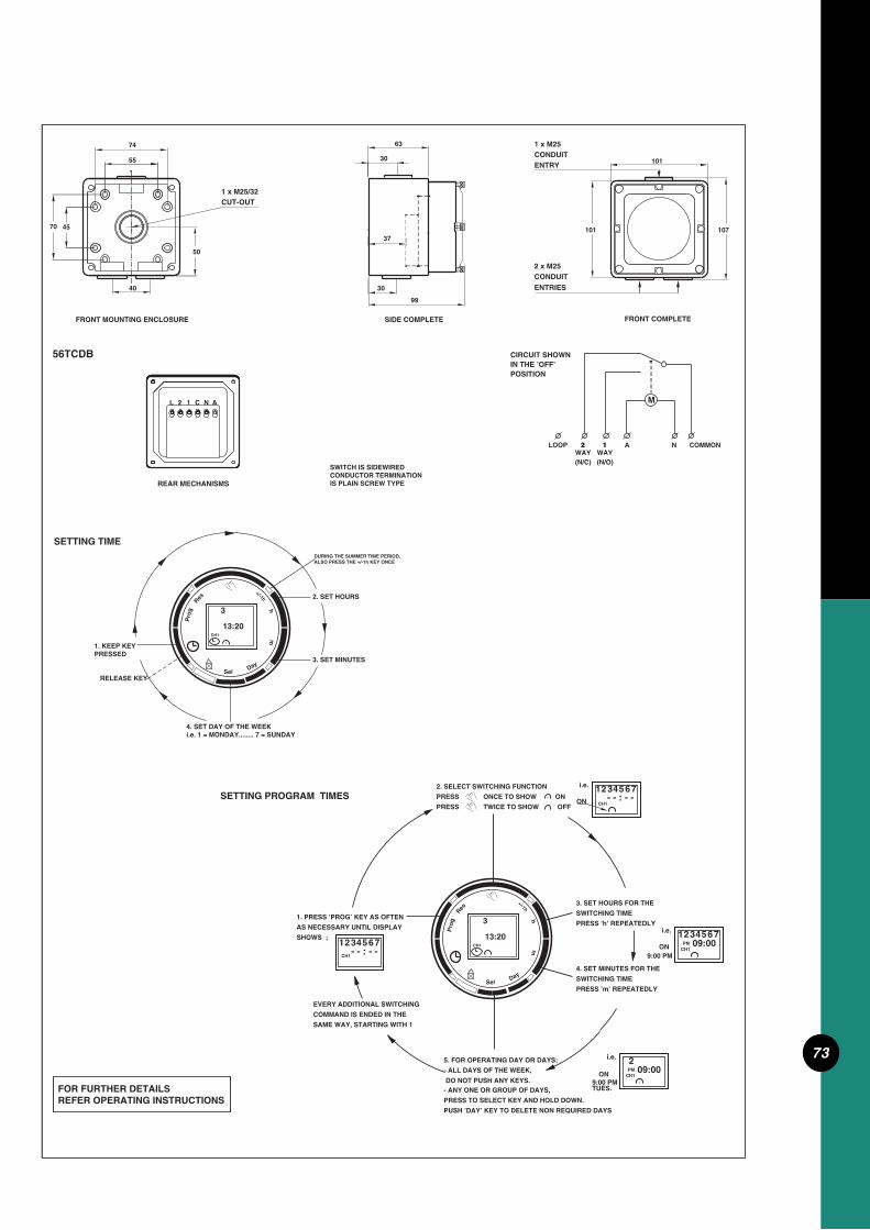
73
REAR MECHANISMS
56TCDB
CUT-OUT1 x M25/32
FRONT MOUNTING ENCLOSURE
40
50
70 45
74
55
99
SIDE COMPLETE
30
37
63
30
107
ENTRIES
2 x M25CONDUIT
FRONT COMPLETE
101
ENTRY
1 x M25CONDUIT
101
CIRCUIT SHOWN IN THE ’OFF’ POSITION
WAYLOOP
WAY22 N11 A
M
COMMON
(N/O)(N/C)
L 2 1 C N A
3
13:20CH1
h
Pro
g
m
1. KEEP KEYPRESSED
DURING THE SUMMER TIME PERIOD,ALSO PRESS THE +/-1h KEY ONCE
2. SET HOURS
3. SET MINUTES
4. SET DAY OF THE WEEKi.e. 1 = MONDAY........ 7 = SUNDAY
RELEASE KEY
SETTING TIME
SWITCH IS SIDEWIREDCONDUCTOR TERMINATION IS PLAIN SCREW TYPE
1. PRESS ’PROG’ KEY AS OFTEN
AS NECESSARY UNTIL DISPLAY
SHOWS ;3
CH1
21 4 675- - : - -
PRESS ONCE TO SHOW ON
2. SELECT SWITCHING FUNCTION
PRESS TWICE TO SHOW OFF CH1
i.e. 4312 65 7ON
PRESS ’h’ REPEATEDLY
SWITCHING TIME
3. SET HOURS FOR THE
4. SET MINUTES FOR THE
SWITCHING TIME
PRESS ’m’ REPEATEDLY
i.e.
09:007
CH1
1ON
6532PM
4
- - : - -
9:00 PM
DO NOT PUSH ANY KEYS.
5. FOR OPERATING DAY OR DAYS;
- ALL DAYS OF THE WEEK,
- ANY ONE OR GROUP OF DAYS,
PRESS TO SELECT KEY AND HOLD DOWN.
PUSH ’DAY’ KEY TO DELETE NON REQUIRED DAYS
CH1
9:00 PM
i.e. 2PM 09:00
TUES.
ON
SAME WAY, STARTING WITH 1
COMMAND IS ENDED IN THE
EVERY ADDITIONAL SWITCHING
SETTING PROGRAM TIMES
FOR FURTHER DETAILSREFER OPERATING INSTRUCTIONS
DaySel
Res
+/-1h
Day
13:20
+/-1h
CH1
Pro
g 3
mh
Sel
Res

74
SIDE COMPLETEFRONT MOUNTING ENCLOSURE
140 1 x M20/25
1 x M20/25
CUT-OUT
CUT-OUT
40
50
75
50
18
38
2 x M20CONDUITENTRIES
1 x M25CONDUITENTRY
198
FRONT COMPLETE
101
204
56AI42056AI410
18
138
REAR MECHANISMS
TERMINALS AREACTUALLY ANGLED,SHOWN HERE FLATFOR PICTORIAL REPRESENTATION
56AI52056AI510
REAR MECHANISMS
L3L1
L2
E
L3
E
L2
L1 N
SIDE COMPLETEFRONT MOUNTING ENCLOSURE
56AI31556AI310
45
40
REAR MECHANISMS
50
CUT-OUTS1 x M20/25
18
18
38
74
101
76
2 x M20
ENTRIESCONDUIT
CONDUIT1 x M25
ENTRY
FRONT COMPLETE
101
1075
A N
E
APPLIANCE INLET IS BACKWIREDCONDUCTOR TERMINATION IS PLAIN SCREW TYPE
73
CONDUCTOR TERMINATIONIS PLAIN SCREW TYPE
56AI320

75
45
192
95
56CB1N56CB2N56CB3N56EL2N56EL4N56EL2
56AI532
56AI55056AI540
SHOWN HERE FLATACTUALLY ANGLED,
REPRESENTATIONFOR PICTORIAL
TERMINALS ARE
56AI450
56AI43256AI440
REAR MECHANISMS
L1
E
L3
L2
REAR MECHANISMS
L3L1 N
E
L2
63
SIDE COMPLETEFRONT MOUNTING ENCLOSURE
140165
CUT-OUT
CUT-OUT
1 x M32
1 x M25
40
50
50
30
75
5555 22
198
165 ENTRIESCONDUIT2 x M25
FRONT COMPLETE
204
ENTRYCONDUIT1 x M32
101
CONDUCTOR TERMINATIONIS PLAIN SCREW TYPE
DIN RAIL BRACKETPROVIDED WITH KIT
56AI332

76
50
95
190
MOUNTING BRACKET

77

78
157
254
56FWL
SIDE COMPLETE FRONT COMPLETE
198
63
80
FRONT MOUNTING ENCLOSURE
165 140
50
50
5555
75
CUT-OUT
CUT-OUT1 x M25
1 x M32
1 x M25CONDUIT ENTRY
CONDUIT ENTRY1 x M25
FRONT MOUNTING ENCLOSURE
50
140165
56WL
CUT-OUT1 x M32
CUT-OUT1 x M25
5555
50
75
FRONT COMPLETESIDE COMPLETE
22CONDUIT
91
1 x M25CONDUITENTRY
ENTRY
198 204
63 1 x M25
MOUNTING PLATE FOR 56FLW
110
90
240
140
8.4
22
101
204
MOUNTING PLATE GASKETLENS
22
22
215190

79

80

81
E
REAR MECHANISMS
N
L
A
FRONT MOUNTING ENCLOSURE
235260 70 45
40
50
CUT-OUT1 x M25
1 x M32CUT-OUT
55
50
75
CUT-OUT1 x M25
SIDE COMPLETE FRONT COMPLETE
300
30
100
2 x M25CONDUIT
ENTRIES
30
63
ENTRY
CONDUITCONDUIT
294
101
1 x M25
56CTC
43
37
36
56CTC15
LOOP2 WAY1 WAYCOMMON
NA
E
REAR MECHANISMS
N
N
E
A
ASWITCHES ARE 30 SERIES MECH
L
A
N E
N
E
MOTORTIMER
1OFF
2
COMMON
MOTOR
OVERRIDEMANUAL
A
AUTOMATICT 1
C
56CTC SERIES WIRING IDENTIFICATION
C
1ON/OFF
C
1
2L C
2L
1
TIMECONTACTS
POWERINPUT
SOCKET OUTLET
2
1
C L2
1
LC
CABLEINCOMING
TERMINALS

82
FRONT MOUNTING ENCLOSURE
56CTC2S01556CTC2S0
CUT-OUT1 x M25
165 140
CUT-OUT1 x M40
FRONT COMPLETE REAR MECHANISMS
E L
N A
E
N
L
A
37
22
172
50
22
CUT-OUT
CUT-OUT1 x M25
50
1 x M32
42
152
18
100
SIDE COMPLETE
43
CONDUIT
ENTRIES
2 x M25
63
ENTRIES
CONDUITCONDUIT2 x M20
198
198204
1
C
2L
1
C
2L
REFER TO 56CTC , 56CTC15 WIRING DIAGRAM

83
FRONT MOUNTING ENCLOSURE
260 235 70
FRONT COMPLETE
SIDE COMPLETE
20
100
REAR MECHANISMS
ENTRIES
CONDUIT2 x M25
300
20
63
CONDUITCONDUIT
ENTRIES
2 x M25
294
N
E
A
L
2 x M25CUT-OUTS
2 x M40CUT-OUTS
2 x M32CUT-OUTS
22
172
42
152
56CTCT15056CTCT150/1256CTCT150/24
LOW VOLTAGE TERMINALS
EXTRA LOW VOLTAGE TERMINALS
REFER TO 56CTC , 56CTC15 WIRING DIAGRAM
198
1
2L
C C
1
2L

84
FRONT MOUNTING ENCLOSURE
56T15056T150/12
SIDE COMPLETE FRONT COMPLETE
40
45260 235 70
50
30
96
1 x M25CUT-OUT
CUT-OUT1 x M32
55
75
1 x M25CUT-OUT
50
30
63
CONDUIT
ENTRIES
2 x M25
300 294
101ENTRY
CONDUITCONDUIT1 x M25
56T150/24
TERMINALSLOW VOLTAGE
TERMINALSEXTRA LOW VOLTAGE
TRANSFORMER

85
FRONT COMPLETE
ENTRIES
CONDUIT2 x M25
300 294
FRONT MOUNTING ENCLOSURE
2 x M25CONDUITCONDUIT
ENTRIES
152
42
CUT-OUTS
CUT-OUTS
2 x M40
2 x M32
SIDE COMPLETE
96
22
260 235 70
22
CUT-OUTS2 x M25
172
22
63
56T150/256T150/12/256T150/24/2
TERMINALS1 x LOW VOLTAGE
TERMINALS2 x EXTRA LOW VOLTAGE
198
TRANSFORMER

86
FRONT MOUNTING ENCLOSURE
CUT-OUTS
SIDE COMPLETE
2 x M20CONDUITENTRIES
1 x M20/25
50
40
18
1 x M25CONDUITENTRY74
45
38
18
FRONT MOUNTING ENCLOSURE
70 45
CUT-OUT1 x M25/32
40
50
5555
74
SIDE COMPLETE
30
63
22
CONDUITENTRIES
2 x M25
CONDUITENTRY
1 x M32
63
SIDE COMPLETEFRONT MOUNTING ENCLOSURE
40
165 140
5555
75
50
30
50
CUT-OUT
1 x M25CUT-OUT
1 x M32
22
2 x M25CONDUITENTRIES
1 x M32CONDUITENTRY
ENTRYCONDUIT1x M40
FRONT MOUNTING ENCLOSURE SIDE COMPLETE
140165
50
1 x M25CUT-OUT
1 x M32CUT-OUT
5555
50
75
45
45
1001x M40CONDUITENTRY
101107
107 101
204 198
198204
FRONT
FRONT
FRONT
FRONT
ONE 56B BRIDGE PROVIDED
ONE 56B BRIDGE PROVIDED
101
101
101
101
56E1
56ES1
56E2
56ED2

87
18
18
FRONT MOUNTING ENCLOSURE
140
40
50
2 x M20/25CUT-OUTS
50
74
SIDE COMPLETE
38
2 x M20
ENTRIESCONDUIT
ENTRYCONDUIT1 x M25
SIDE COMPLETE
105
30
CONDUIT2 x M25
ENTRIES
22
63
ENTRIES
1 x M32CONDUIT
FRONT COMPLETE
101
FRONT MOUNTING ENCLOSURE
40
165 140
5555
75
50
50
CUT-OUT
1 x M25CUT-OUT
1 x M32
204198
1 x M32
FRONT MOUNTING ENCLOSURE
40
70260 235 45
50
SIDE COMPLETE
30
CUT-OUT1 x M25
CUT-OUT
55
75
22
CUT-OUT1 x M25
50
63
CONDUITENTRIES
2 x M25
ENTRYCONDUIT1 x M32
198204
294300
ONE 56B BRIDGE PROVIDED
FRONT
TWO 56B BRIDGES PROVIDED
FRONT
101
101
10156ES2
56E2/4EL
56E3
COMPLETE WITH DIN RAILTO SUIT 4EL RCD’S

88
FRONT MOUNTING ENCLOSURE
CUT-OUT1 x M25
165 140
CUT-OUT1 x M40
22
172
5022
CUT-OUT
CUT-OUT1 x M25
50
1 x M32
42
152
22
SIDE COMPLETE
63
198204
2 x M32
ENTRIESCONDUIT
2 x M25CONDUITENTRIES
56E4
397
FRONT MOUNTING ENCLOSURE
CUT-OUT
CUT-OUT
1 x M25CUT-OUT
1 x M32
50
7555
1 x M40
50
SIDE COMPLETE
30
391
1 x M32
ENTRYCONDUIT
63
30
2 x M25CONDUITENTRIES
1 x M25CUT-OUT
40
28165333358 97
56E4VH
FRONT
TWO 56B BRIDGES AND TWO 56DV DIVIDERS PROVIDED
ONE 56DV DIVIDER PROVIDEDTWO 56B BRIDGES AND
FRONT
101
198

89
AB
AB
AB
AB
C C
22
D
18
E
F
F
22
FRONT
18
DE
FRONT
CC
G H I G
IHGH
I H G H
GHIG
G G
H
I
GG
H
I
H H
II
G G IGH
G G
HGI
CatalogueNumber Gangs
No. A B C DDimensions(mm)
E FConduit Entries
G H ICut Out Provisions
Dividers56 DV
Bridges56B
PointsMounting
56E656E856E956E16 16
89
6
392
392294
294
398
398300
300
392
198294
198
63
6363
63
2 x M25
2 x M253 x M25
2 x M25
2 x M32
2 x M323 x M32
2 x M32
25
2525
25
32
3232
32
12
66
4
8
46
3
48
2828
2440
4040
40
56E6 56E9
56E1656E8

90

91
FRONT MOUNTING ENCLOSURE SIDE COMPLETE
103
270
110
38
38
63
30
215
40
75
320
2 x M32/40CUT-OUTS
2 x M32CONDUIT ENTRIES
CONDUIT 1 x M40
ENTRIES
66CV45066CV46366CV55066CV56366CV75066CV763
160
FRONT COMPLETE
ION
0OFF

92
66P450
116 74
260
30
67
66CV. (CONT)
L3
T3
CONDUCTOR TERMINATIONSWITCH IS SIDE WIRED
SWITCH IS MOUNTED
IS PRESSURE PLATE TYPE
MECHANISM
SWITCH IS MOUNTED
SWITCH IS SIDE WIREDCONDUCTOR TERMINATIONIS PRESSURE PLATE TYPE
66CV46366CV450
ON BACK PLATE
L1
L2
L3
L1
E
L3
E
L2
66CV56366CV550
L1
L3
L2
ON BACK PLATE
n
L2
L1
L3
E
MECHANISM
NL1
E
L2
L3
PE
PE
T1 T2
L1 L2
T3
L3
PE
PE
T2T1
L2L1
SWITCH IS SIDE WIREDCONDUCTOR TERMINATIONIS PRESSURE PLATE TYPE
66CV76366CV750
n
L1
L2
L3
ON BACK PLATESWITCH IS MOUNTED
n
L1
L2
L3
C1
MECHANISM
L1
E
C2
N
E
L2
L3TERMINALS ARE
FOR PICTORIAL REPRESENTATION
ACTUALLY ANGLED,SHOWN HERE FLAT
n
L2
L1
L3
N
N
PE T1
PE L1
T2 T3
L2 L3
N
N
66P46366P55066P56366P75066P763
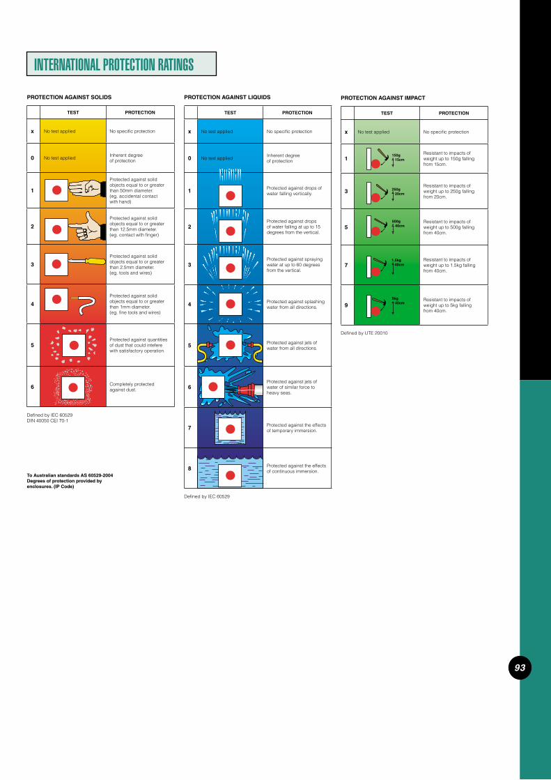
93
INTERNATIONAL PROTECTION RATINGS
Defi ned by UTE 20010
PROTECTION AGAINST IMPACT
TEST PROTECTION
x No test applied No specifi c protection
1Resistant to impacts of weight up to 150g falling from 15cm.
3Resistant to impacts of weight up to 250g falling from 20cm.
5Resistant to impacts of weight up to 500g falling from 40cm.
7Resistant to impacts of weight up to 1.5kg falling from 40cm.
9Resistant to impacts of weight up to 5kg falling from 40cm.
150g 15cm
250g 20cm
500g 40cm
1.5kg 40cm
5kg 40cm
To Australian standards AS 60529-2004Degrees of protection provided by enclosures. (IP Code)
TEST PROTECTION
x No test applied No specifi c protection
0 No test appliedInherent degree of protection
1 Protected against drops of water falling vertically.
2
Protected against drops of water falling at up to 15 degrees from the vertical.
3Protected against spraying water at up to 60 degrees from the vertical.
4 Protected against splashing water from all directions.
5 Protected against jets of water from all directions.
6Protected against jets of water of similar force to heavy seas.
7 Protected against the effects of temporary immersion.
8 Protected against the effects of continuous immersion.
Defi ned by IEC 60529
PROTECTION AGAINST LIQUIDS
TEST PROTECTION
x No test applied No specifi c protection
0 No test appliedInherent degree of protection
1
Protected against solid objects equal to or greater than 50mm diameter. (eg. accidental contact with hand)
2
Protected against solid objects equal to or greater than 12.5mm diameter.(eg. contact with fi nger)
3
Protected against solid objects equal to or greater than 2.5mm diameter. (eg. tools and wires)
4
Protected against solid objects equal to or greater than 1mm diameter.(eg. fi ne tools and wires)
5Protected against quantities of dust that could intefere with satisfactory operation.
6 Completely protected against dust.
Defi ned by IEC 60529DIN 40050 CEI 70-1
PROTECTION AGAINST SOLIDS

94
The following technical terms are brief descriptions indicating the tests involved to attain ratings. For further information refer to the stan- dards indicated.
M-Rating (Refer AS/NZS3133)Clipsal switches and switched
socket outlets are marked with an M-Rating. This indicates that these products have been tested and found suitable for switching locked rotor current.
In part, this test involves 50 opera-tions, make and break of the nomi-nated locked rotor current at 0.5 power factor lagging. The switch will not fail to interrupt the current or fail in any way electrically or mechanically.
AC-21 (refer AS/NZS3947)Switching of resistive loads, includ-
ing moderate overloads In part this involves 5 make and
break operations, at 11/2 times rated current and 1.1 times rated voltage at 0.95 cos.
Additional mechanical no load and electrical endurance tests at rated current and voltage at 0.95 cos are conducted.
AC-22 (refer AS/NZS3947)Switching of mixed resistive and
inductive loads, including moderate overloads.
In part this involves 5 make and break operations at 3 times rated current and 1.1 times rated voltage at 0.65 cos.
Additional mechanical no load and electrical endurance tests at rated cur-rent and voltage at 0.65 cos.
TECHNICAL TERMS
AC-23 (refer AS/NZS3947)Switching of motor loads or highly
inductive loads.In part this involves 5 make and
break operations at:10 times rated current make.1.1 times rated voltage make.0.35 cos.8 times rated current break.1.1 times rated voltage break.0.35 cos.Additional mechanical at no load
and electrical endurance tests at rated current and voltage at 0.35 cos are conducted.
AC-15 (refer AS/NZS3947)Control of electromagnetic loads
(>72VA).

95
Cable size No. and diameter Overall diameter - nominal area of wires for of AS 3000 of conductor standard conductor table E7 mm2 No./mm mm
0.5 1/0.80 2.5 1 1/1.13 2.9 1.5 1/1.38 3.2 7/0.50 3.3 2.5 1/1.78 3.6 7/0.67 3.8 4 7/0.85 4.8 6 7/1.04 5.3 10 7/1.35 6.3 16 7/1.70 7.3 25 19/1.35 9.4 35 19/1.53 10.4 50 19/1.78 12.0 70 19/2.14 13.8 95 37/1.78 16 120 37/2.03 17.7 150 37/2.25 19.7 185 37/2.52 22 240 61/2.25 25.1 300 61/2.52 27.9 400 61/2.85 31.4 500 61/3.20 34.9 630 127/2.52 38.9
Measure Symbol Unit
Length S mArea A m2
Volume V m3
Weight m kgDensity P kg/m3
Time t sFrequency F HzRotary Speed n s-1
Linear Speed v ms-1
Acceleration a ms-2
Power F N (Newton)Pressure P Pa (Pascal)Torque M NmWork W J (Joule)Power P W (Watt)Reactive Voltampere VarVoltampere V.ACurrent I A (Ampere)Operational Current Ith AConventional Enclosed Ithe AThermal CurrentVoltage U V (Volts)Insulated Voltage Ui VOperational Voltage Ue VResistance R (Ohm)Impedance Z Reactance X Reluctance S A/WbCapacitance C F (Farad)Quantity of Electricity Q C (Coulomb)Magnetic Field Strength H A/mMagnetic Flux Ø Wb (Weber)Inductance L H (Henry)Magnetic Flux Density B T (Tesca)Temperature t OC (Centigrade)Illuminance E l x (Lux)Luminance L cd/m2
Luminous Flux Ø lm (Lumen)Luminous Intensity I cd (Candela)
Dimensions, standard copper and aluminium conductors1 core 0.6/1kV PVC insulated cable to AS 3147, 75oCNote: For exact dimensions refer to manufacturers’ details.
TECHNICAL TABLES
kW = Line Amps x Line Volts x 1.732 x P.F. 1000
kVA = Line Amps x Line Volts x 1.732 1000
kW = kV.A x P.F.
Abbreviations for Multiples and Sub Multiples
T tera 1012
G giga 109
M mega 106
k kilo 103
d deci 10-1
c centi 10-2
m milli 10-3
u micro 10-6
n nano 10-9
p pico 10-12
ABBREVIATIONS
USEFUL 3-PHASE FORMULAE
Electric Motors
Power Output = Power Input x Effi ciency
kW Output = kW Input x Effi ciency
kW Output = 1.732 x Line Volts x Line Amps x P.F. x Effi ciency 1000
kV.A Input = 1.732 x Line Volts x Line Amps 1000
Line Amperes = 1000 x kW Output Line Volts x 1.732 x P.F. x Effi ciency
Line Amperes = 1000 x kV.A Input Line Volts x 1.732
The Power Factor is usually taken as 0.8 (as an all-round fi gure) but this varies with the speed and size of the motor.The effi ciency varies from 85% in small motors to 90% and over for large motors.

96
Quality Non-SI Unit Metric Conversion Factors Metric (SI) to (Approximate) Non-SI Non-SI Units To Metric (SI) Units
Length Inch (in) Millimetre (mm) or 1 in = 25.4mm 1 cm = 0.39 in Centimetre (cm) Foot (ft) Centimetre (cm) or 1 ft = 30.5 cm 1 m = 3.28 ft Metre (m) Yard (yd) Metre (m) 1 yd = 0.914 m 1 m = 1.09 yd Mile Kilometre (km) 1 mile = 1.61 km 1 km = 0.62 mile
Area Square Inch (in2) Square Millimetre (mm2) 1 in2 = 645 mm2 1 mm2 = 0.002 in2
Square Inch (in2) Square Centimetre (cm2) 1 in2 = 6.45 cm2 1cm2 = 0.155 in2
Square Foot (ft2) Square Centimetre (cm2) 1 ft2 = 929 cm2 1 m2 = 10.76 ft2
or Square Metre (m2) Square Yard (yd2) Square Metre (m2) 1 yd2 = 0.836m2 1 m2 = 1.20 yd2
Acre Hectare (ha) 1 acre = 0.405 ha 1 ha = 2.47 acres Square Mile Square Kilometre (km2) 1 Square Mile = 2.59 km2 1 km2 = 0.387 sq. mile
Volume Cubic Inch (in3) Cubic Centimetre (cm3) 1 in3 = 16.4 cm3 1 cm3 = 0.06 in3
Cubic Inch (ft3) Cubic Decimetre (dm3) or 1 ft3 = 28.3 dm3 1 m3+ = 35.3 ft3
Cubic Yard (yd3) Cubic Metre (m3) 1 yd3 = 0.765m3 1 m3 = 1.31 yd3
Volume Fluid Once UK (fl . oz UK) Millilitre (ml) 1 fl . oz (UK) = 28.4 ml 1 ml = 0.035 fl . oz (UK)(Fluids) Pint UK (pt UK) Millilitre (ml) or Litre (l) 1 pint UK = 568 ml 1 l = 1.76 pint (UK) Gallon UK (gal UK) Litre (l) or Cubic Metre (m3) 1 gal UK = 4.55 l 1 m3 = 220 gallons (UK) Fluid Once US (Fl. oz US) Millilitre (ml) 1 fl . oz (US) = 29.6 ml 1 ml = 0.034 fl . oz (US) Pint US (gal US) Litre (l) or Millilitre 1 pint (US) = 473 ml 1 l = 2.11 pint (US) Gallon US (gal US) Litre 1 gallon (US) = 3.79 l 1 l = 0.264 gallon (US)
Mass Ounce (oz) Gram (g) 1 oz = 28.3 g 1 g = 0.035 oz Pound (lb) Gram (g) or kilogram (kg) 1 lb = 454 g 1 kg = 2.20 lb Ton Tonne (t) 1 ton = 1.02 tonne 1 tonne = 0.984 ton tael Gram (g) 1 tael= 37.8 g 1 g = 0.026 tael Catty Kilogram (kg) 1 catty = 0.605 kg 1 kg = 1.65 cattoes Picul Kilogram (kg) 1 picul = 60.50 kg 1 kg = 0.017 picul
Force Pound Force (lbf) Newton (N) 1 lbf = 4.45 N 1 N = 0.225 lbf Kilogram Force (kgf) Newton (N) 1 kgf = 9.81 N 1 N = 0.102 kgf
Pressure Pound Force per square kilopascal (kPa) 1 psi = 6.86 kPa 1 kPa = 0.145 psi inch (psi) Kilogram force per kilopascal (kpa) 1 kgf/cm2 = 98 kPa 1 kPa = 0.01 kgf/cm2
square centimetre (kgf/cm2) Inch of water (in H2O) Pascal (Pa) 1 in H2O = 249 Pa 1 Pa = 0.004 in H2O Bar kilopascal (kPa) 1 Bar = 100 kPa 1 kPA = 0.01 bar
Velocity Mile per hour (mph) Kilometre per hour (km/h) 1 mile = 1.61 km/h 1 km/h = 0.62 mph
Temperature Fahrenheit temp. (F) Celsius temp. (C) oC = 5 (oF - 32) oF = (9 x oC) + 32 9 5
Density Pound per cubic inch Gram per cubic 1 lb/in3 = 27.7 t/m3 1 t/m3 = 0.036 lb/in3
(lb/in3) centimetre (g/cm3) = tonne per cubic metre (t/m3) Pound per cubic foot Kilogram per cubic metre 1 lb/ft3 = 16.02 kg/m3 1 kg/m3 = 0.06 lb/ft3
(lb/ft3+) (kg/m3) Ton per cubic yard Tonne per cubic metre (t/m3) 1 ton/yd = 1.33 t/m3 1 t/m3 = 0.752 ton/yd3 (ton/yd3)
Energy British thermal unit (Btu) Kilojoule (kJ) 1 Btu = 1.06 kJ 1 kJ = 0.948 Btu Therm Megajoule (MJ) 1 Therm =106 MJ 1 MJ = 9.48 x 10⁻³ therm Calorie (dietician) Kilojoule (kJ) 1 Cal (dietician) = 4 kJ 1 kJ = 0.23 Cal (dietician)
Power Horsepower (hp) Kilowatt (kW) 1 hp = 0.746 kW 1 kW = 1.34 hp
Fuel Mile per gallon (mpg) Litres per 100 m (n) x mpg = 2821/100 km (n) x 1/100 km = 282Consumption n n
COMMON CONVERSION FACTORS

97
Catalogue Product Illustration Number Description
NUMERICAL INDEX
56/01/1 .............................................................................39 .....................................................7156/01X ..............................................................................39 .....................................................7156/2PB .............................................................................19 .....................................................7056/2PBS1 .....................................................................19 .....................................................7056/32 ..................................................................................38 .....................................................7156AI310 ..........................................................................15 .....................................................7456AI315 ..........................................................................15 .....................................................7456AI410 ..........................................................................15 .....................................................7456AI420 ..........................................................................15 .....................................................7456AI432 ..........................................................................15 .....................................................7556AI440 ..........................................................................15 .....................................................7556AI450 ..........................................................................15 .....................................................7556AI510 ..........................................................................15 .....................................................7456AI520 ..........................................................................15 .....................................................7456AI532 ..........................................................................15 .....................................................7556AI540 ..........................................................................15 .....................................................7556AI550 ..........................................................................15 .....................................................7556B .......................................................................................34 ............................................................
56C210 ............................................................................12 .....................................................4856C215/32 ...................................................................12 .....................................................4856C3/110 ......................................................................12 .....................................................4856C310L ........................................................................12 .....................................................4856C310RP ...................................................................12 .....................................................4856C310HD ..................................................................12 .....................................................4856C310 ............................................................................12 .....................................................4856C310RC ..................................................................30 .....................................................5456C310D .......................................................................12 .....................................................4856C310EL2P ............................................................31 ............................................................
56C315 ............................................................................12 .....................................................4856C315RC ..................................................................30 .....................................................5456C315D .......................................................................12 .....................................................4856C315ELP ................................................................31 ............................................................
56C315HD ..................................................................12 .....................................................4856C320 ............................................................................12 .....................................................4956C332 ............................................................................12 .....................................................5056C410 ............................................................................12 .....................................................4956C410RC ..................................................................30 .....................................................5556C416K ........................................................................12 .....................................................4956C420 ............................................................................12 .....................................................4956C420RC ..................................................................30 .....................................................5556C432 ............................................................................12 .....................................................5056C432RC ..................................................................30 .....................................................5456C440 ............................................................................12 .....................................................5056C440RC ..................................................................30 .....................................................5456C450 ............................................................................12 .....................................................5056C510 ............................................................................12 .....................................................4956C510RC ..................................................................30 .....................................................5456C520 ............................................................................12 .....................................................4956C520RC ..................................................................30 .....................................................5456C532 ............................................................................12 .....................................................5056C532RC ..................................................................30 .....................................................5456C540 ............................................................................12 .....................................................5056C540RC ..................................................................30 .....................................................5456C550 ............................................................................12 .....................................................5056C610 ............................................................................12 .....................................................4956C710 ............................................................................12 .....................................................4956C720 ............................................................................12 .....................................................49
56CB4N ..........................................................................36 .....................................................7556CSC310 ...................................................................28 ............................................................
56CSC315 ...................................................................28 ............................................................
56CSC410 ...................................................................28 ............................................................
56CSC420 ...................................................................28 ............................................................
56CSC432 ...................................................................28 ............................................................
56CSC440 ...................................................................28 ............................................................
56CSC450 ...................................................................28 ............................................................
Catalogue Product Illustration Number Description
56CSC510 ...................................................................28 ............................................................
56CSC520 ...................................................................28 ............................................................
56CSC532 ...................................................................28 ............................................................
56CSC540 ...................................................................28 ............................................................
56CSC550 ...................................................................28 ............................................................
56CTC ..............................................................................32 .....................................................8156CTC2SO .................................................................32 .....................................................8256CTC2SO15 ..........................................................32 .....................................................8256CTC15 .......................................................................32 .....................................................8156CTCT150 ...............................................................32 .....................................................8356CTCT150/12 ......................................................32 .....................................................8356CTCT150/24 ......................................................32 .....................................................8356CV310 ........................................................................12 .....................................................5156CV310HD ..............................................................12 .....................................................5156CV315 ........................................................................12 .....................................................5156CV315HD ..............................................................12 .....................................................5156CV410 ........................................................................12 .....................................................5256CV416K ...................................................................12 .....................................................5256CV420 ........................................................................12 .....................................................5256CV432 ........................................................................12 .....................................................5356CV440 ........................................................................12 .....................................................5356CV450 ........................................................................12 .....................................................5356CV510 ........................................................................12 .....................................................5256CV520 ........................................................................12 .....................................................5256CV532 ........................................................................12 .....................................................5356CV540 ........................................................................12 .....................................................5356CV550 ........................................................................12 .....................................................5356CV610 ........................................................................12 .....................................................5156CV710 ........................................................................12 .....................................................5156CV720 ........................................................................12 .....................................................5156DB2 ...............................................................................38 .....................................................9056D .......................................................................................25 ............................................................
56DB3 ...............................................................................38 .....................................................9056DB4 ...............................................................................38 .....................................................9056XDB4 ..........................................................................38 .....................................................9056DB6 ...............................................................................38 .....................................................9056XDB6 ..........................................................................38 .....................................................9056DB9 ...............................................................................38 .....................................................9056DV ...................................................................................34 ............................................................
56EI .....................................................................................34 .....................................................8656E2 ...................................................................................34 .....................................................8656E2/4EL ......................................................................34 .....................................................8756E3 ...................................................................................34 .....................................................8756E4 ...................................................................................34 .....................................................8856E4VH ..........................................................................34 .....................................................8856E6 ...................................................................................34 .....................................................8956E8 ...................................................................................34 .....................................................8956E8SB ...........................................................................34 ............................................................
56E9 ...................................................................................34 .....................................................8956E9SB ...........................................................................34 ............................................................
56E16 ................................................................................34 .....................................................8956ED2 ...............................................................................34 .....................................................8656ES1 ...............................................................................34 .....................................................8656ES2 ...............................................................................34 .....................................................8756FA1 ................................................................................39 ............................................................
56FA1B ............................................................................39 ............................................................
56FA2 ................................................................................39 ............................................................
56FA2B ............................................................................39 ............................................................
56FA3 ................................................................................39 ............................................................
56FA3B ............................................................................39 ............................................................
56FA4 ................................................................................39 ............................................................
56FA4B ............................................................................39 ............................................................
56FWL ..............................................................................33 .....................................................7856HPG1 ..........................................................................37 ............................................................
56HPG2/1 ....................................................................37 ............................................................
56HPG2/2 ....................................................................37 ............................................................

98
Catalogue Product Illustration Number Description
56HPG4/3 ....................................................................37 ............................................................
56HPG4/4 ....................................................................37 ............................................................
56JB1 ................................................................................38 .....................................................9056JB2 ................................................................................38 .....................................................9056JB3 ................................................................................38 .....................................................9056JB4 ................................................................................38 .....................................................9056JB1SWA ..................................................................39 ............................................................
56K1SW115 ..............................................................21 .....................................................6956K1SW115HS .....................................................21 .....................................................6956K1SW115MS ....................................................21 .....................................................6956K1SW120 ..............................................................21 .....................................................6856K1SW132 ..............................................................21 .....................................................6856K1SW132HS .....................................................21 .....................................................6856K1SW132MS ....................................................21 .....................................................6856K1SW150 ..............................................................21 .....................................................6856K1SW220 ..............................................................21 .....................................................6856K1SW232 ..............................................................21 .....................................................6856K1SW250 ..............................................................21 .....................................................6856K1SW310 ..............................................................21 .....................................................6856K1SW310HS .....................................................21 .....................................................6856K1SW310MS ....................................................21 .....................................................6856K1SW320 ..............................................................21 .....................................................6856K1SW332 ..............................................................21 .....................................................6856K1SW350 ..............................................................21 .....................................................6856K2SW115 ..............................................................21 .....................................................6956K2SW115MS ....................................................21 .....................................................6956K2SW120 ..............................................................21 .....................................................6856K2SW132 ..............................................................21 .....................................................6856K2SW132MS ....................................................21 .....................................................6856K2SW150 ..............................................................21 .....................................................6856K2SW220 ..............................................................21 .....................................................6856K2SW232 ..............................................................21 .....................................................6856K2SW250 ..............................................................21 .....................................................6856K2SW310 ..............................................................21 .....................................................6856K2SW310MS ....................................................21 .....................................................6856K2SW320 ..............................................................21 .....................................................6856K2SW332 ..............................................................21 .....................................................6856K2SW350 ..............................................................21 .....................................................6856L1 ....................................................................................35 ............................................................
56L1/22 ...........................................................................35 ............................................................
56L1/22/2 ......................................................................35 ............................................................
56L1/30 ...........................................................................35 ............................................................
56L1/30/2 ......................................................................35 ............................................................
56L2 ....................................................................................35 ............................................................
56L3 ....................................................................................35 ............................................................
56L4 ....................................................................................35 ............................................................
56LK ...................................................................................25 ............................................................
56MF ..................................................................................25 .....................................................6956MS ..................................................................................34 ............................................................
56P210 ............................................................................26 .....................................................7956P215/32 ...................................................................26 .....................................................7956P3/110 .......................................................................26 .....................................................7956P310L .........................................................................26 .....................................................7956P310RP ...................................................................26 .....................................................7956P310 ............................................................................26 .....................................................7956P315 ............................................................................26 .....................................................7956P320 ............................................................................26 .....................................................7956P320F ........................................................................26 .....................................................7956P410 ............................................................................26 .....................................................7956P410G .......................................................................27 ............................................................
56P416K ........................................................................26 .....................................................7956P420 ............................................................................26 .....................................................7956P420G .......................................................................27 ............................................................
56P432 ............................................................................26 .....................................................7956P440 ............................................................................26 .....................................................7956P450 ............................................................................26 .....................................................79
56P510 ............................................................................26 .....................................................7956P510G .......................................................................27 ............................................................
56P520 ............................................................................26 .....................................................7956P520G .......................................................................27 ............................................................
56P532 ............................................................................26 .....................................................7956P540 ............................................................................26 .....................................................7956P550 ............................................................................26 .....................................................7956P610 ............................................................................26 .....................................................7956P710 ............................................................................26 .....................................................7956P720 ............................................................................26 .....................................................7956PA320 .........................................................................26 .....................................................7956PA332 .........................................................................26 .....................................................7956PA410 .........................................................................26 .....................................................7956PA410G ....................................................................27 ............................................................
56PA416K ....................................................................26 .....................................................7956PA415KG ...............................................................27 ............................................................
56PA420 .........................................................................26 .....................................................7956PA420G ....................................................................27 ............................................................
56PA432 .........................................................................26 .....................................................7956PA432G ....................................................................27 ............................................................
56PA440 .........................................................................26 .....................................................7956PA440G ....................................................................27 ............................................................
56PA450 .........................................................................26 .....................................................7956PA450G ....................................................................27 ............................................................
56PA510 .........................................................................26 .....................................................7956PA510G ....................................................................27 ............................................................
56PA520 .........................................................................26 .....................................................7956PA520G ....................................................................27 ............................................................
56PA532 .........................................................................26 .....................................................7956PA532G ....................................................................27 ............................................................
56PA540 .........................................................................26 .....................................................7956PA540G ....................................................................27 ............................................................
56PA550 .........................................................................26 .....................................................7956PA550G ....................................................................27 ............................................................
56PA610 .........................................................................26 .....................................................7956PA610G ....................................................................27 ............................................................
56PA710 .........................................................................26 .....................................................7956PA710G ....................................................................27 ............................................................
56PA720 .........................................................................26 .....................................................7956PA720G ....................................................................27 ............................................................
56PB ...................................................................................19 .....................................................7056PBS ..............................................................................19 .....................................................7056PBS1 ...........................................................................19 .....................................................7056PBS2 ...........................................................................19 .....................................................7056PC ..................................................................................27 ............................................................
56PCI .................................................................................27 ............................................................
56PC2 ...............................................................................27 ............................................................
56PMK .................................................................................... ............................................................
56PO410 .......................................................................29 .....................................................8056PO420 .......................................................................29 .....................................................8056PO432 .......................................................................29 .....................................................8056PO440 .......................................................................29 .....................................................8056PO450 .......................................................................29 .....................................................8056PO510 .......................................................................29 .....................................................8056PO520 .......................................................................29 .....................................................8056PO532 .......................................................................29 .....................................................8056PO540 .......................................................................29 .....................................................8056PO550 .......................................................................29 .....................................................8056POK ..............................................................................28 .....................................................8056POKI ............................................................................28 .....................................................8056RC ..................................................................................30 .....................................................5156SB4 ...............................................................................40 .....................................................7656SB13 ...........................................................................40 .....................................................7756SC2 ...............................................................................27 ............................................................
56SC310RC ..............................................................30 .....................................................5756SC315RC ..............................................................30 .....................................................57
Catalogue Product Illustration Number Description

99
Catalogue Product Illustration Number Description
Catalogue Product Illustration Number Description
56SC410RC ..............................................................30 .....................................................5856SC420RC ..............................................................30 .....................................................5856SC432RC ..............................................................30 .....................................................5956SC440RC ..............................................................30 .....................................................5956SC510RC ..............................................................30 .....................................................5856SC520RC ..............................................................30 .....................................................5856SC532RC ..............................................................30 .....................................................5956SC540RC ..............................................................30 .....................................................5956SO210 .......................................................................14 .....................................................6056SO215/32 ..............................................................14 .....................................................6056SO3/110 ..................................................................14 .....................................................6056SO310 .......................................................................14 .....................................................6056SO310A ...................................................................14 .....................................................6056SO310L ....................................................................14 .....................................................6056SO315 .......................................................................14 .....................................................6056SO310RP ..............................................................14 .....................................................6056SO315A ...................................................................14 .....................................................6056SO320 .......................................................................14 .....................................................6156SO320F ...................................................................14 .....................................................6056SO320G ..................................................................15 ............................................................
56SO332 .......................................................................14 .....................................................6156SO332G ..................................................................15 ............................................................
56SO410 .......................................................................14 .....................................................6156SO410G ..................................................................15 ............................................................
56SO416K ...................................................................14 .....................................................6156SO416KG ..............................................................15 ............................................................
56SO420 .......................................................................14 .....................................................6156SO420G ..................................................................15 ............................................................
56SO432 .......................................................................14 .....................................................6156SO432G ..................................................................15 ............................................................
56SO440 .......................................................................14 .....................................................6156SO440G ..................................................................15 ............................................................
56SO450 .......................................................................14 .....................................................6156SO450G ..................................................................15 ............................................................
56SO4ELP15 ...........................................................31 ............................................................
56SO510 .......................................................................14 .....................................................6156SO510G ..................................................................15 ............................................................
56SO520 .......................................................................14 .....................................................6156SO520G ..................................................................15 ............................................................
56SO532 .......................................................................14 .....................................................6156SO532G ..................................................................15 ............................................................
56SO540 .......................................................................14 .....................................................6156SO540G ..................................................................15 ............................................................
56SO550 .......................................................................14 .....................................................6156SO550G ..................................................................15 ............................................................
56SO610 .......................................................................14 .....................................................6156SO610G ..................................................................15 ............................................................
56SO710 .......................................................................14 .....................................................6156SO710G ..................................................................15 ............................................................
56SO720 .......................................................................14 .....................................................6156SO720G ..................................................................15 ............................................................
56SPOK .........................................................................28 .....................................................8056SSR ..............................................................................24 .....................................................6956SSW2/10 ................................................................17 .....................................................7156SSW2/15 ................................................................17 .....................................................7156SSW10 .....................................................................17 .....................................................7156SSW10/I ..................................................................17 .....................................................7156SW110 ......................................................................16 .....................................................6256SSW15 .....................................................................17 .....................................................6256SW110HD .............................................................16 .....................................................6256SW110/I ..................................................................16 .....................................................6256SW110/2 .................................................................16 .....................................................6256SW115 ......................................................................16 .....................................................6256SW115HD .............................................................16 .....................................................6256SW115/2 .................................................................16 .....................................................6256SW120 ......................................................................16 .....................................................62
56SW132 ......................................................................16 .....................................................6356SW150 ......................................................................16 .....................................................6356SW163 ......................................................................16 .....................................................6356SW220 ......................................................................16 .....................................................6256SW220CO ............................................................18 .....................................................6756SW232 ......................................................................16 .....................................................6356SW250 ......................................................................16 .....................................................6356SW263 ......................................................................16 .....................................................6356SW310 ......................................................................16 .....................................................6256SW320 ......................................................................16 .....................................................6256SW320C .................................................................16 .....................................................6456SW320R .................................................................18 .....................................................6756SW332 ......................................................................16 .....................................................6356SW332C .................................................................16 .....................................................6556SW350 ......................................................................16 .....................................................6356SW350C .................................................................16 .....................................................6556SW363 ......................................................................16 .....................................................6356SW363/2 .................................................................16 .....................................................6456SW420 ......................................................................16 .....................................................6556SW420CO ............................................................18 .....................................................6756SWT216 ..................................................................23 .....................................................7256SWH325 .................................................................18 .....................................................6656SWH340 .................................................................18 .....................................................6656SWH363 .................................................................18 .....................................................6656SWH380 .................................................................18 .....................................................6656SWH425 .................................................................18 .....................................................6656SWH440 .................................................................18 .....................................................6656SWH463 .................................................................18 .....................................................6656T20 ................................................................................26 ............................................................
56T25 ................................................................................26 ............................................................
56T32 ................................................................................26 ............................................................
56T150 .............................................................................33 .....................................................8456T150/2 .......................................................................33 .....................................................8556T150/12 ....................................................................33 .....................................................8456T150/12/2 ..............................................................33 .....................................................8556T150/24 ....................................................................33 .....................................................8456T150/24/2 ..............................................................33 .....................................................8556TC ...................................................................................22 .....................................................7256TC7 ...............................................................................22 .....................................................7256TCB ..............................................................................22 .....................................................7256TCB7 ...........................................................................22 .....................................................7256TCDB ..........................................................................22 .....................................................7256WL ..................................................................................33 .....................................................7866CV450 ........................................................................44 .....................................................9166CV550 ........................................................................44 .....................................................9166CV463 ........................................................................44 .....................................................9166CV563 ........................................................................44 .....................................................9166CV750 ........................................................................44 .....................................................9166CV763 ........................................................................44 .....................................................9166KEY ..............................................................................44 ............................................................
66N415 ............................................................................44 ............................................................
66PCC ..............................................................................44 ............................................................
66P450 ............................................................................44 .....................................................9266P450G .......................................................................45 ............................................................
66P463 ............................................................................44 .....................................................9266P463G .......................................................................45 ............................................................
66P550 ............................................................................44 .....................................................9266P550G .......................................................................45 ............................................................
66P563 ............................................................................44 .....................................................9266P563G .......................................................................45 ............................................................
66P750 ............................................................................44 .....................................................9266P750G .......................................................................45 ............................................................
66P763 ............................................................................44 .....................................................9266P763G .......................................................................45 ............................................................
66SO450G ..................................................................45 ............................................................
66SO463G ..................................................................45 ............................................................

100
Catalogue Product Illustration Number Description
66SO550G ..................................................................45 ............................................................
66SO563G ..................................................................45 ............................................................
66SO563G ..................................................................45 ............................................................
66SO750G ..................................................................45 ............................................................
66SO763G ..................................................................45 ............................................................

Product of Clipsal Australia Pty LtdABN 27 007 873 529
Head Offi ce12 Park Terrace, Bowden South Australia 5007Telephone (08) 8269 0511Facsimile (08) 8340 1724Internet clipsal.comE-Mail [email protected]
National Customer Service Enquiries:1300 2025 25
National Customer Service Facsimile:1300 2025 56
International EnquiriesInternational Sales and MarketingTelephone + 61 8 8269 0587Facsimile + 61 8 8340 7350E-Mail [email protected]
clipsal.comNew ZealandClipsal Industries (NZ) Ltd
Telephone (09) 576 3403Facsimile (09) 576 1015E-Mail headoffi [email protected]
Customer ServiceFree Fax (0508) 250 305Auckland/Mobile Phone (09) 572 0014Free Phone (0508) CLIPSAL 2547725
You can fi nd this brochure and many others online in PDF format at:clipsal.com
Follow the links off the home page or access the following page directly: clipsal.com/wat_lib_pdf.cfm
Clipsal Australia Pty Ltd reserves the right to change specifi cations, modify designs and dis con tin ue items without incurring obligation and whilst every effort is made to ensure that descriptions, specifi cations and other in for ma tion in this catalogue are correct, no warranty is given in respect thereof and the company shall not be liable for any error therein.
©Copyright Clipsal Australia Pty Ltd 2006.All rights reserved.This material is copyright under Australian and international laws. Except as permitted under the relevant law, no part of this work may be reproduced by any process without prior written permission of and acknowledgement to Clipsal Australia Pty Ltd. C
2-00
3
O/N 826-812 Apr 06/03
QualityEndorsedCompany
ISO 9002LIC 413
StandardsAustralia


![Live The Race - 2015 Clipsal 500 Adelaide - 26 Feb - 1 Mar 2015 [2015 Clipsal]](https://static.fdocuments.us/doc/165x107/55cdef58bb61eb04538b46a6/live-the-race-2015-clipsal-500-adelaide-26-feb-1-mar-2015-2015-clipsal-55cf9c268d5c3.jpg)


![Cold Chisel To Rock The 2015 Clipsal 500 Adelaide [2015 Clipsal]](https://static.fdocuments.us/doc/165x107/55c37b9ebb61eb6b5e8b469a/cold-chisel-to-rock-the-2015-clipsal-500-adelaide-2015-clipsal.jpg)
![Robby Gordon Stadium Super Trucks Set For The 2015 Clipsal 500 Adelaide [2015 Clipsal]](https://static.fdocuments.us/doc/165x107/55cdee90bb61eb13538b45cb/robby-gordon-stadium-super-trucks-set-for-the-2015-clipsal-500-adelaide-2015-55cf9c3a09017.jpg)

