556 IEEE TRANSACTIONS ON CONTROL SYSTEMS · PDF fileModel Predictive Multi-Objective Vehicular...
11
556 IEEE TRANSACTIONS ON CONTROL SYSTEMS TECHNOLOGY, VOL. 19, NO. 3, MAY 2011 Model Predictive Multi-Objective Vehicular Adaptive Cruise Control Shengbo Li, Keqiang Li, Rajesh Rajamani, and Jianqiang Wang Abstract—This paper presents a novel vehicular adaptive cruise control (ACC) system that can comprehensively address issues of tracking capability, fuel economy and driver desired response. A hierarchical control architecture is utilized in which a lower controller compensates for nonlinear vehicle dynamics and en- ables tracking of desired acceleration. The upper controller is synthesized under the framework of model predictive control (MPC) theory. A quadratic cost function is developed that con- siders the contradictions between minimal tracking error, low fuel consumption and accordance with driver dynamic car-following characteristics while driver longitudinal ride comfort, driver permissible tracking range and rear-end safety are formulated as linear constraints. Employing a constraint softening method to avoid computing infeasibility, an optimal control law is nu- merically calculated using a quadratic programming algorithm. Detailed simulations with a heavy duty truck show that the developed ACC system provides significant benefits in terms of fuel economy and tracking capability while at the same time also satisfying driver desired car following characteristics. Index Terms—Adaptive cruise control (ACC), driver character- istics, fuel economy, model predictive control (MPC), tracking ca- pability. I. INTRODUCTION A DAPTIVE cruise control (ACC) is an enhancement of the traditional cruise control (CC) system that improves driver convenience, reduces driver workload and has the poten- tial to improve vehicle safety. Current ACC systems that have been commercialized by automotive manufacturers focus en- tirely on the tasks of tracking a desired spacing from a pre- ceding vehicle or tracking a desired speed. Researchers have re- cently started to explore the introduction of additional objectives into an ACC, e.g., fuel economy and driver desired response. Tsugawa [1] and Ioannou [2], [3] suggested the use of ITS tech- nologies, including adaptive cruise control, to reduce fuel con- sumption of vehicles. Marsden et al. [4] considered issues of driver desired response and indicated the necessity to adapt to drivers’ individual driving characteristics. While it would be beneficial to have an ACC that simultaneously considers issues of spacing control, fuel economy, and adaptability to individual Manuscript received June 06, 2009; revised March 11, 2010; accepted March 24, 2010. Manuscript received in final form April 21, 2010. First published May 24, 2010; current version published April 15, 2011. Recommended by Associate Editor S. Liu. This work was supported by the National Science Foundation of China under Grant 50975155. S. Li, K. Li, and J. Wang are with State Key Laboratory of Automotive Safety and Energy, Tsinghua University, Beijing 100084, P.R. China (e-mail: likq@ts- inghua.edu.cn). R. Rajamani is with the University of Minnesota, Minneapolis, MN 55455 USA (e-mail: [email protected]). Digital Object Identifier 10.1109/TCST.2010.2049203 driver characteristics, the design of the control system becomes a significant challenge when there are multiple objectives in- volved. A review of current literature shows that an ACC that con- siders many objectives has not yet been developed. For CC sys- tems with a given route, Latterman et al. [5] proposed an op- timal control algorithm that minimizes the fuel consumption globally. Ioannou et al. [2], [3] pointed out that the smoothing feature of ACC vehicles could improve fuel efficiency of mixed traffic flow, including that of the ACC vehicle itself. Their re- search further disclosed that the effect was more obvious under conditions of large acceleration, lane changing and cut-in/off. On its basis, Zhang et al. [6] developed a nonlinear filter-based PI controller, which restricted acceleration levels to fulfill fuel- saving requirements. Similarly, Jonsson et al. [7] proposed a dy- namic programming based offline control method. It reduced the fuel consumption while allowing more tracking error. With respect to driver desired response, ACC is usually designed to accord with three kinds of driver features: driver desired dis- tance characteristic, driver longitudinal ride comfort and driver dynamic car-following characteristic. The first feature is nor- mally embodied by integrating a driver desired clearance (DDC) model into the car-following system [5]–[13]. For the second feature, the vehicle acceleration and its derivative are typically restrained in order to avoid large acceleration and jerk [8], [9]. For the third feature, a common method is to integrate directly or indirectly a driver car-following (DCF) model into the ACC controller. For instance, Persson et al. [10] combined a linear DCF model and a PI method together to develop an upper layer controller for ACC. Using a second order inertial system as a reference model, Higashimata et al. [11] designed an ACC al- gorithm based on a model matching control structure to improve driver desired response in dynamic car-following scenarios. However, the mentioned objectives such as tracking capa- bility, fuel economy, and driver desired response usually con- flict with each other. It is inadequate to design an ACC al- gorithm simply considering only one of them. The improve- ment of fuel consumption usually decreases the acceleration performance and lowers the tracking capability. This will lead to two problems consequently: 1) when the preceding car accel- erates, larger inter-vehicular distance occurs due to the deficient acceleration performance, resulting in frequent vehicle cut-ins from adjacent lanes; 2) when the preceding vehicle decelerates, inter-vehicular distance shortens quickly and rear-end collisions happen more easily. On the contrary, if an ACC system pur- sues good tracking capability only, it leads to unnecessary ac- celeration and emergency braking, which also deteriorates the fuel economy of vehicles to an extent. Similarly, when drivers cannot adapt themselves to their ACC system, frequent driver 1063-6536/$26.00 © 2010 IEEE
Transcript of 556 IEEE TRANSACTIONS ON CONTROL SYSTEMS · PDF fileModel Predictive Multi-Objective Vehicular...
556 IEEE TRANSACTIONS ON CONTROL SYSTEMS TECHNOLOGY, VOL. 19, NO. 3, MAY 2011
Model Predictive Multi-Objective Vehicular AdaptiveCruise Control
Shengbo Li, Keqiang Li, Rajesh Rajamani, and Jianqiang Wang
Abstract—This paper presents a novel vehicular adaptive cruisecontrol (ACC) system that can comprehensively address issues oftracking capability, fuel economy and driver desired response.A hierarchical control architecture is utilized in which a lowercontroller compensates for nonlinear vehicle dynamics and en-ables tracking of desired acceleration. The upper controller issynthesized under the framework of model predictive control(MPC) theory. A quadratic cost function is developed that con-siders the contradictions between minimal tracking error, low fuelconsumption and accordance with driver dynamic car-followingcharacteristics while driver longitudinal ride comfort, driverpermissible tracking range and rear-end safety are formulatedas linear constraints. Employing a constraint softening methodto avoid computing infeasibility, an optimal control law is nu-merically calculated using a quadratic programming algorithm.Detailed simulations with a heavy duty truck show that thedeveloped ACC system provides significant benefits in terms offuel economy and tracking capability while at the same time alsosatisfying driver desired car following characteristics.
Index Terms—Adaptive cruise control (ACC), driver character-istics, fuel economy, model predictive control (MPC), tracking ca-pability.
I. INTRODUCTION
A DAPTIVE cruise control (ACC) is an enhancement ofthe traditional cruise control (CC) system that improves
driver convenience, reduces driver workload and has the poten-tial to improve vehicle safety. Current ACC systems that havebeen commercialized by automotive manufacturers focus en-tirely on the tasks of tracking a desired spacing from a pre-ceding vehicle or tracking a desired speed. Researchers have re-cently started to explore the introduction of additional objectivesinto an ACC, e.g., fuel economy and driver desired response.Tsugawa [1] and Ioannou [2], [3] suggested the use of ITS tech-nologies, including adaptive cruise control, to reduce fuel con-sumption of vehicles. Marsden et al. [4] considered issues ofdriver desired response and indicated the necessity to adapt todrivers’ individual driving characteristics. While it would bebeneficial to have an ACC that simultaneously considers issuesof spacing control, fuel economy, and adaptability to individual
Manuscript received June 06, 2009; revised March 11, 2010; accepted March24, 2010. Manuscript received in final form April 21, 2010. First published May24, 2010; current version published April 15, 2011. Recommended by AssociateEditor S. Liu. This work was supported by the National Science Foundation ofChina under Grant 50975155.
S. Li, K. Li, and J. Wang are with State Key Laboratory of Automotive Safetyand Energy, Tsinghua University, Beijing 100084, P.R. China (e-mail: [email protected]).
R. Rajamani is with the University of Minnesota, Minneapolis, MN 55455USA (e-mail: [email protected]).
Digital Object Identifier 10.1109/TCST.2010.2049203
driver characteristics, the design of the control system becomesa significant challenge when there are multiple objectives in-volved.
A review of current literature shows that an ACC that con-siders many objectives has not yet been developed. For CC sys-tems with a given route, Latterman et al. [5] proposed an op-timal control algorithm that minimizes the fuel consumptionglobally. Ioannou et al. [2], [3] pointed out that the smoothingfeature of ACC vehicles could improve fuel efficiency of mixedtraffic flow, including that of the ACC vehicle itself. Their re-search further disclosed that the effect was more obvious underconditions of large acceleration, lane changing and cut-in/off.On its basis, Zhang et al. [6] developed a nonlinear filter-basedPI controller, which restricted acceleration levels to fulfill fuel-saving requirements. Similarly, Jonsson et al. [7] proposed a dy-namic programming based offline control method. It reducedthe fuel consumption while allowing more tracking error. Withrespect to driver desired response, ACC is usually designed toaccord with three kinds of driver features: driver desired dis-tance characteristic, driver longitudinal ride comfort and driverdynamic car-following characteristic. The first feature is nor-mally embodied by integrating a driver desired clearance (DDC)model into the car-following system [5]–[13]. For the secondfeature, the vehicle acceleration and its derivative are typicallyrestrained in order to avoid large acceleration and jerk [8], [9].For the third feature, a common method is to integrate directlyor indirectly a driver car-following (DCF) model into the ACCcontroller. For instance, Persson et al. [10] combined a linearDCF model and a PI method together to develop an upper layercontroller for ACC. Using a second order inertial system as areference model, Higashimata et al. [11] designed an ACC al-gorithm based on a model matching control structure to improvedriver desired response in dynamic car-following scenarios.
However, the mentioned objectives such as tracking capa-bility, fuel economy, and driver desired response usually con-flict with each other. It is inadequate to design an ACC al-gorithm simply considering only one of them. The improve-ment of fuel consumption usually decreases the accelerationperformance and lowers the tracking capability. This will leadto two problems consequently: 1) when the preceding car accel-erates, larger inter-vehicular distance occurs due to the deficientacceleration performance, resulting in frequent vehicle cut-insfrom adjacent lanes; 2) when the preceding vehicle decelerates,inter-vehicular distance shortens quickly and rear-end collisionshappen more easily. On the contrary, if an ACC system pur-sues good tracking capability only, it leads to unnecessary ac-celeration and emergency braking, which also deteriorates thefuel economy of vehicles to an extent. Similarly, when driverscannot adapt themselves to their ACC system, frequent driver
1063-6536/$26.00 © 2010 IEEE
LI et al.: MODEL PREDICTIVE MULTI-OBJECTIVE VEHICULAR ADAPTIVE CRUISE CONTROL 557
intervention inevitably occurs. This action not only affects theimprovement of tracking capability, but also deprives ACC ofits benefit of reducing driver workload and enhancing vehiclesafety. Therefore, it is necessary to comprehensively deal withall the three objectives simultaneously in one framework.
The design of an ACC system with multiple objectives canbe naturally cast into a model predictive control (MPC) frame-work. MPC has already proved its merit in ACC design in litera-ture, in spite of its considerable computational burden. However,the use of MPC has only been done to improve system perfor-mance in terms of tracking capability and to ensure proper tran-sitions between different modes of operation. To ensure safetyand good tracking capability, Corona et al. [12], [13] applied aHybrid MPC approach to vehicular-following control. Kohut etal. [14] designed a predictive control strategy that optimizes theengine torque to tradeoff fuel consumption and trip time whilekeeping the vehicle within a specified speed envelope. For tran-sitional maneuver modes, Bageshwar et al. [15] presented anMPC-based headway control algorithm with acceleration limi-tations incorporated explicitly to meet the requirements of ridecomfort and safety.
Unlike the previous publications, the present paper focuseson the use of MPC to achieve multiple objectives during the ve-hicle-following mode in ACC. The multiple objectives soughtto be achieved are desired driver response, minimal fuel con-sumption and minimization of car following error. In addition,hard and soft constraints that ensure vehicle safety and take ac-tuator limits and ride quality into consideration are included inthe problem formulation. This paper is organized as follows. InSection II, the lower layer controller is discussed under a hierar-chical control structure and a three-state space model of the car-following system is built. In Section III, based on the frameworkof MPC, a predictive optimization problem is constructed con-sidering tracking capability, fuel economy and driver desired re-sponse. In Section IV, a constraint softening method is adoptedto address computing infeasibility issues and the optimal controllaw of MO-ACC is numerically solved. In Section IV, its suc-cess is demonstrated with a nonlinear high-order longitudinalmodel of a heavy duty (H/D) truck.
II. MODELING OF CAR-FOLLOWING SYSTEM
A. Nonlinearity Compensation of Vehicle LongitudinalDynamics
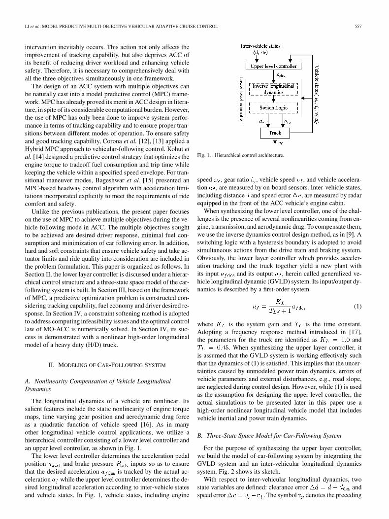
The longitudinal dynamics of a vehicle are nonlinear. Itssalient features include the static nonlinearity of engine torquemaps, time varying gear position and aerodynamic drag forceas a quadratic function of vehicle speed [16]. As in manyother longitudinal vehicle control applications, we utilize ahierarchical controller consisting of a lower level controller andan upper level controller, as shown in Fig. 1.
The lower level controller determines the acceleration pedalposition and brake pressure inputs so as to ensurethat the desired acceleration is tracked by the actual ac-celeration while the upper level controller determines the de-sired longitudinal acceleration according to inter-vehicle statesand vehicle states. In Fig. 1, vehicle states, including engine
Fig. 1. Hierarchical control architecture.
speed , gear ratio , vehicle speed , and vehicle accelera-tion , are measured by on-board sensors. Inter-vehicle states,including distance and speed error , are measured by radarequipped in the front of the ACC vehicle’s engine cabin.
When synthesizing the lower level controller, one of the chal-lenges is the presence of several nonlinearities coming from en-gine, transmission, and aerodynamic drag. To compensate them,we use the inverse dynamics control design method, as in [9]. Aswitching logic with a hysteresis boundary is adopted to avoidsimultaneous actions from the drive train and braking system.Obviously, the lower layer controller which provides acceler-ation tracking and the truck together yield a new plant withits input and its output , herein called generalized ve-hicle longitudinal dynamic (GVLD) system. Its input/output dy-namics is described by a first-order system
(1)
where is the system gain and is the time constant.Adopting a frequency response method introduced in [17],the parameters for the truck are identified as and
. When synthesizing the upper layer controller, itis assumed that the GVLD system is working effectively suchthat the dynamics of (1) is satisfied. This implies that the uncer-tainties caused by unmodeled power train dynamics, errors ofvehicle parameters and external disturbances, e.g., road slope,are neglected during control design. However, while (1) is usedas the assumption for designing the upper level controller, theactual simulations to be presented later in this paper use ahigh-order nonlinear longitudinal vehicle model that includesvehicle inertial and power train dynamics.
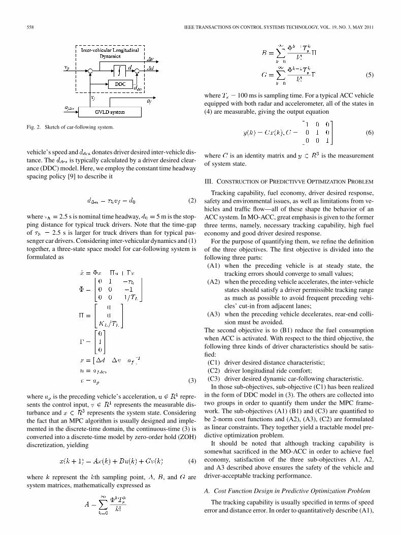
B. Three-State Space Model for Car-Following System
For the purpose of synthesizing the upper layer controller,we build the model of car-following system by integrating theGVLD system and an inter-vehicular longitudinal dynamicssystem. Fig. 2 shows its sketch.
With respect to inter-vehicular longitudinal dynamics, twostate variables are defined: clearance error andspeed error . The symbol denotes the preceding
558 IEEE TRANSACTIONS ON CONTROL SYSTEMS TECHNOLOGY, VOL. 19, NO. 3, MAY 2011
Fig. 2. Sketch of car-following system.
vehicle’s speed and donates driver desired inter-vehicle dis-tance. The is typically calculated by a driver desired clear-ance (DDC) model. Here, we employ the constant time headwayspacing policy [9] to describe it
(2)
where 2.5 s is nominal time headway, 5 m is the stop-ping distance for typical truck drivers. Note that the time-gapof 2.5 s is larger for truck drivers than for typical pas-senger car drivers. Considering inter-vehicular dynamics and (1)together, a three-state space model for car-following system isformulated as
(3)
where is the preceding vehicle’s acceleration, repre-sents the control input, represents the measurable dis-turbance and represents the system state. Consideringthe fact that an MPC algorithm is usually designed and imple-mented in the discrete-time domain, the continuous-time (3) isconverted into a discrete-time model by zero-order hold (ZOH)discretization, yielding
(4)
where represent the th sampling point, , , and aresystem matrices, mathematically expressed as
(5)
where 100 ms is sampling time. For a typical ACC vehicleequipped with both radar and accelerometer, all of the states in(4) are measurable, giving the output equation
(6)
where is an identity matrix and is the measurementof system state.
III. CONSTRUCTION OF PREDICTIVVE OPTIMIZATION PROBLEM
Tracking capability, fuel economy, driver desired response,safety and environmental issues, as well as limitations from ve-hicles and traffic flow—all of these shape the behavior of anACC system. In MO-ACC, great emphasis is given to the formerthree terms, namely, necessary tracking capability, high fueleconomy and good driver desired response.
For the purpose of quantifying them, we refine the definitionof the three objectives. The first objective is divided into thefollowing three parts:(A1) when the preceding vehicle is at steady state, the
tracking errors should converge to small values;(A2) when the preceding vehicle accelerates, the inter-vehicle
states should satisfy a driver permissible tracking rangeas much as possible to avoid frequent preceding vehi-cles’ cut-in from adjacent lanes;
(A3) when the preceding vehicle decelerates, rear-end colli-sion must be avoided.
The second objective is to (B1) reduce the fuel consumptionwhen ACC is activated. With respect to the third objective, thefollowing three kinds of driver characteristics should be satis-fied:(C1) driver desired distance characteristic;(C2) driver longitudinal ride comfort;(C3) driver desired dynamic car-following characteristic.In those sub-objectives, sub-objective (C1) has been realized
in the form of DDC model in (3). The others are collected intotwo groups in order to quantify them under the MPC frame-work. The sub-objectives (A1) (B1) and (C3) are quantified tobe 2-norm cost functions and (A2), (A3), (C2) are formulatedas linear constraints. They together yield a tractable model pre-dictive optimization problem.
It should be noted that although tracking capability issomewhat sacrificed in the MO-ACC in order to achieve fueleconomy, satisfaction of the three sub-objectives A1, A2,and A3 described above ensures the safety of the vehicle anddriver-acceptable tracking performance.
A. Cost Function Design in Predictive Optimization Problem
The tracking capability is usually specified in terms of speederror and distance error. In order to quantitatively describe (A1),
LI et al.: MODEL PREDICTIVE MULTI-OBJECTIVE VEHICULAR ADAPTIVE CRUISE CONTROL 559
a 1-norm function of tracking errors is adopted as the cost func-tion of MPC in [12] and a 2-norm function is used in [15]. Theformer gives equal consideration to the tracking errors of dif-ferent degrees while the latter tends to penalize larger errorsand neglect smaller ones. Actually, in a car-following process,a driver only responds to large enough tracking errors and isn’tsensitive to tiny ones. This means the driver maintains a con-stant pedal position when the tracking errors are in the rangeof specific thresholds. This feature is called Action Point [18].Only when the errors exceed the Action Point, the driver willthen adjust throttle pedal or brake pedal to bring tracking errorsback into the range of Action Point. This helps reduce fuel con-sumption, since the driver doesn’t frequently accelerate or de-celerate under small-tracking errors. Therefore, from the view-point of the driver, it is more reasonable to employ the 2-normof tracking errors to quantify (A1)
(7)
where and are the corresponding weighting coeffi-cients.
A direct method to quantify the sub-objective (B2) is to in-clude the fuel injection amount of engine as a variable in thecost function. However, this has a nonlinear relationship withthe system states in (3). Such a cost function will definitely leadto a nonlinear programming problem in MPC. Its large com-puting complexity makes its difficult to be solved in a samplingtime less than 100 ms. As mentioned in [1] and [6], fuelconsumption is mainly dominated by vehicle acceleration levelsif neglecting extremes in engine operational area. In a car-fol-lowing process with same mileage and average travel speed, fuelconsumption of a vehicle increases as the absolute of its accel-eration increases. Regarding the fuel economy of vehicles, thepenalty for vehicle acceleration has a similar effect as that ofa penalty directly on the fuel consumption, but resulting in aQP rather than a nonlinear program. Here, considering that theinput and output of GVLD system are similar to each other, thesub-objective (B2) is defined as a 2-norm function of desiredlongitudinal acceleration and its derivative instead of actual lon-gitudinal acceleration and jerk
(8)
where is the weighting coefficient of is that of. In (8), the second term in the right-hand side can not
only restrain frequent variation of engine speed by reducing thelongitudinal jerk, but also helps to improve longitudinal ridecomfort of passengers.
In the car-following process during a transient maneuver, thetracking errors are not zero. The driver normally manipulatesthe acceleration pedal or brake pedal to make the vehicle trackthe driver’s desired reference trajectory. Here, the trajectory iscalculated by a DCF model. The tracking errors between systemoutput and reference trajectory is minimized to embody the sub-objective (C3). Therefore, its quantification is a 2-norm of theerror between actual acceleration and reference acceleration
(9)
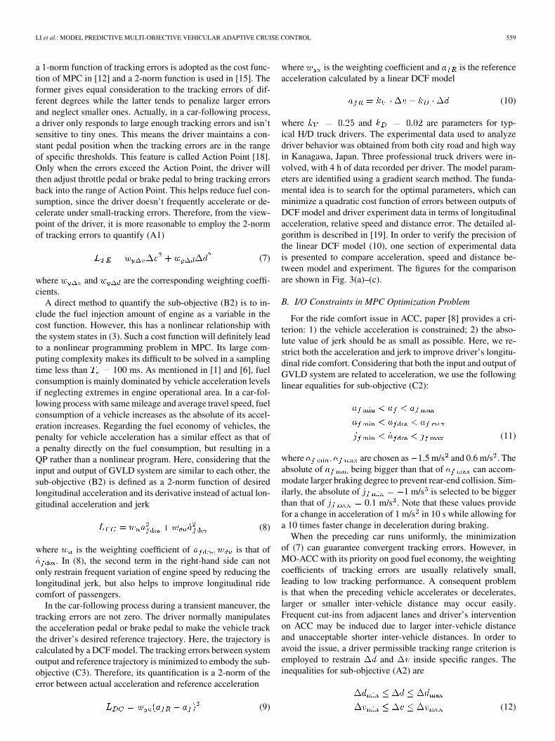
where is the weighting coefficient and is the referenceacceleration calculated by a linear DCF model
(10)
where and are parameters for typ-ical H/D truck drivers. The experimental data used to analyzedriver behavior was obtained from both city road and high wayin Kanagawa, Japan. Three professional truck drivers were in-volved, with 4 h of data recorded per driver. The model param-eters are identified using a gradient search method. The funda-mental idea is to search for the optimal parameters, which canminimize a quadratic cost function of errors between outputs ofDCF model and driver experiment data in terms of longitudinalacceleration, relative speed and distance error. The detailed al-gorithm is described in [19]. In order to verify the precision ofthe linear DCF model (10), one section of experimental datais presented to compare acceleration, speed and distance be-tween model and experiment. The figures for the comparisonare shown in Fig. 3(a)–(c).
B. I/O Constraints in MPC Optimization Problem
For the ride comfort issue in ACC, paper [8] provides a cri-terion: 1) the vehicle acceleration is constrained; 2) the abso-lute value of jerk should be as small as possible. Here, we re-strict both the acceleration and jerk to improve driver’s longitu-dinal ride comfort. Considering that both the input and output ofGVLD system are related to acceleration, we use the followinglinear equalities for sub-objective (C2):
(11)
where are chosen as 1.5 m/s and 0.6 m/s . Theabsolute of being bigger than that of can accom-modate larger braking degree to prevent rear-end collision. Sim-ilarly, the absolute of 1 m/s is selected to be biggerthan that of 0.1 m/s . Note that these values providefor a change in acceleration of 1 m/s in 10 s while allowing fora 10 times faster change in deceleration during braking.
When the preceding car runs uniformly, the minimizationof (7) can guarantee convergent tracking errors. However, inMO-ACC with its priority on good fuel economy, the weightingcoefficients of tracking errors are usually relatively small,leading to low tracking performance. A consequent problemis that when the preceding vehicle accelerates or decelerates,larger or smaller inter-vehicle distance may occur easily.Frequent cut-ins from adjacent lanes and driver’s interventionon ACC may be induced due to larger inter-vehicle distanceand unacceptable shorter inter-vehicle distances. In order toavoid the issue, a driver permissible tracking range criterion isemployed to restrain and inside specific ranges. Theinequalities for sub-objective (A2) are
(12)
560 IEEE TRANSACTIONS ON CONTROL SYSTEMS TECHNOLOGY, VOL. 19, NO. 3, MAY 2011
Fig. 3. Comparison of experiment data and DCF model. (a) Acceleration. (b)Vehicle speed. (c) Distance.
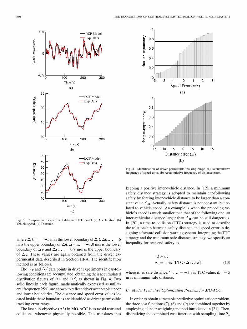
where 5 m is the lower boundary of 6m is the upper boundary of 1.0 m/s is the lowerboundary of and 0.9 m/s is the upper boundaryof . These values are again obtained from the driver ex-perimental data described in Section III-A. The identificationmethod is as follows.
The and data points in driver experiments in car-fol-lowing conditions are accumulated, obtaining their accumulateddistribution figures of and , as shown in Fig. 4. Twosolid lines in each figure, mathematically expressed as unilat-eral frequency 25%, are shown to reflect driver acceptable upperand lower boundaries. The distance and speed error values lo-cated inside these boundaries are identified as driver permissibletracking error range.
The last sub-objective (A3) in MO-ACC is to avoid rear-endcollisions, whenever physically possible. This translates into
Fig. 4. Identification of driver permissible tracking range. (a) Accumulativefrequency of speed error. (b) Accumulative frequency of distance error.
keeping a positive inter-vehicle distance. In [12], a minimumsafety distance strategy is adopted to maintain car-followingsafety by forcing inter-vehicle distance to be larger than a con-stant value . Actually, safety distance is not constant, but re-lated to vehicle speed. An example is when the preceding ve-hicle’s speed is much smaller than that of the following one, aninter-vehicular distance larger than can be still dangerous.In [20], a time-to-collision (TTC) strategy is used to describethe relationship between safety distance and speed error in de-signing a forward collision warning system. Integrating the TTCstrategy and the minimum safe distance strategy, we specify aninequality for rear-end safety as
(13)
where is safe distance, 3 s is TTC value, 5m is minimum safe distance.
C. Model Predictive Optimization Problem for MO-ACC
In order to obtain a tractable predictive optimization problem,the three cost functions (7), (8) and (9) are combined together byemploying a linear weighting method introduced in [21]. Then,discretizing the combined cost function with sampling time
LI et al.: MODEL PREDICTIVE MULTI-OBJECTIVE VEHICULAR ADAPTIVE CRUISE CONTROL 561
and resettling in finite predictive horizon , it yields the costfunction to be optimized
(14)
where is the control increment, isthe length of predictive horizon, denotes the predictedvalue at time based on the information at time isweighting matrix of system output, is that of control input,
is that of control increment, is a transforming matrixrelated to the DCF model. They are expressed as
(15)
In order to obtain the I/O constraints for the predictive opti-mization problem, we rewrite the inequalities related to the con-trol input and its increment in the predictive horizon
(16)
where is the lower boundary ofis the upper boundary of is the
lower boundary of is the upperboundary of . Similarly, we rewrite the inequalities relatedto the system output
(17)
where is the lower boundaryof is the upper boundaryof . Integrating (2) and the definitions of , the inequalityfor rear-end safety can be rewritten as
(18)
where , and are the coefficients, mathematicallyexpressed as
(19)
The problem statement for the upper layer control algorithmof MO-ACC is to minimize the cost function (14) subject to theI/O constraints (16)–(18), and the model of the car-followingsystem (4) and (6)
Subj. to:
I/O constraints: (16), (17), and (18).
Model of car-following
system: (4) and (6). (20)
IV. RECEDING HORIZON CONTROL OF MO-ACC
A. Addressing Computing Infeasibility in MO-ACC Algorithm
A key issue with the MO-ACC algorithm is the computinginfeasibility of the predictive optimization problem. One ofthe representative causes is that the tracking errors exceedthe boundaries of hard constraints because of rapid accelera-tion/deceleration of the preceding vehicle. In such a situation,the problem (20) may have no optimal solution because thehard constraints in (16) and (17) are never satisfied. In order tosolve it, we improve the problem (20) by employing a constraintsoftening method whose fundamental idea is to relax the I/Oconstraints so that they can be violated [22].
First, define a new cost function with an additional quadraticterm of a slack variable
(21)
where is called the slack variable and is its weighting coef-ficient. Then, the I/O constraints (16) and (17) are correspond-ingly transformed into softened constraints with a slack variable
(22)
where are called equal concerns for relaxation(ECR) of are ECRs of are ECRof . Therefore, we have a predictive optimization problemmodified by constraint softening method
Subj. to:
I/O constraints:
Softening constraint (22)
and rear-end safety constraint (18).
Model of car-following
system: (4) and (6). (23)
562 IEEE TRANSACTIONS ON CONTROL SYSTEMS TECHNOLOGY, VOL. 19, NO. 3, MAY 2011
TABLE IPARAMETERS OF MO-ACC CONTROLLER
In MO-ACC, when the hard boundaries of , or are ex-ceeded, the slack variable will automatically become a positivevalue to allow violation of hard constraints, thus avoiding thepotential computing infeasibility. Moreover, the violation de-gree is penalized by the quadratic term of in the cost function.It guarantees that preferable control optimality of MPC algo-rithm is still maintained. When the hard boundaries of , or
are not exceeded, the hard constraints will not be violatedand slack variable becomes zero. The optimization problem (23)degenerates into its standard form (20).
Additionally, the constraint from rear-end safety is notsoftened because rear-end collision is not allowable. Moreover,since constraints on and are capable of being violated,MO-ACC can increase and consequently strengthen thebraking input when rear-end safety constraint is being ex-ceeded. This helps avoid rear-end collisions as far as physicallypossible.
B. Numerical Computation of MO-ACC Control Law
The optimization problem (23) is transformed to a standardquadratic programming (QP) problem, and then solved by aDantzig–Wolfe active set algorithm in each sampling time, thusobtaining the optimal control sequence andthe optimal slack variable . See [22] for detailed procedures.Considering the relationship between the input increment andthe control input, we have the control law of MO-ACC as
(24)
Note: When solving the problem (23), the acceleration of pre-ceding vehicle in predictive horizon must be known. Here, it isactually a recursion of at current step. Descriptions ofhow the can be estimated using a Kalman filter can befound in [23].
Key parameters in the MO-ACC algorithm are listed inTable I.
V. SIMULATIONS AND ANALYSIS
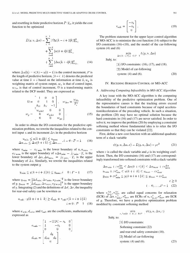
The goal of the following simulations is to evaluate the perfor-mance of the MO-ACC algorithm. These simulations are carriedout with a nonlinear high-order H/D truck longitudinal model,whose schematic diagram is shown in Fig. 5. In Fig. 5, isthe fuel injection amount per cylinder in each stoke, is theengine torque, is the gear position, is the clutch torqueoutput, is the output speed of clutch, is the driving force
Fig. 5. Longitudinal dynamics of H/D truck.
acting on tyres, is the braking force acting on tyres, isthe aerodynamic drag, is the rolling resistance, and is theclimbing resistance.
Here, the diesel engine is divided into engine ECU and enginebody. The ECU is expressed as a complex lookup table with itsinputs being and , etc. The engine body is mainlydescribed by a nonlinear function with it arguments as and
and its dynamics due to intake and combustion process isapproximated by a first-order inertial system. It is assumed thatthe clutch has two modes: engagement and disengagement, ofwhich the former is modeled as a second-order inertial system.The mechanical characteristics of AMT, final gear and the dif-ferential are all assumed as static functions. Pneumatic brakesystem is simplified to be a first order system with pure timedelay. In the following simulation, it is assumed that both theretarder and engine brake are off. Vehicle body is described bya power balance equation between its traction/braking force andexternal resistance such as aerodynamic drag, rolling resistance,and climbing force.
For comparison of performance, a LQR-based ACC algo-rithm (LQACC) is also designed based on the same control plant(4). Like the ride comfort consideration in MO-ACC, its con-trol law is also restrained by longitudinal ride comfort criterion.The weighting matrices of its cost function are identical to thatof MO-ACC, that is and .The LQACC control law is
otherwise (25)
where is the control gain calculated by the LQR method. Inorder to demonstrate the special performance of MO-ACC al-gorithm, the simulation is tested under four kinds of traffic sce-narios: Preceding car’s rapid accelerating scenario, precedingcar’s emergency braking scenario, preceding car’s normal ac-celerating scenario, and city road/highway driving cycles. TheMO-ACC algorithm will be regarded successful if its applica-tion can improve both fuel economy and tracking capabilitywhile also meeting driver desired response and avoiding colli-sions.
A. Preceding Car’s Rapid Acceleration Scenario
In the preceding car’s rapid acceleration scenario, it is as-sumed that the ACC truck and preceding car run at the same
LI et al.: MODEL PREDICTIVE MULTI-OBJECTIVE VEHICULAR ADAPTIVE CRUISE CONTROL 563
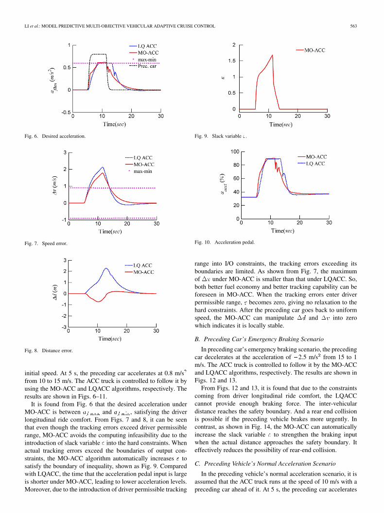
Fig. 6. Desired acceleration.
Fig. 7. Speed error.
Fig. 8. Distance error.
initial speed. At 5 s, the preceding car accelerates at 0.8 m/sfrom 10 to 15 m/s. The ACC truck is controlled to follow it byusing the MO-ACC and LQACC algorithms, respectively. Theresults are shown in Figs. 6–11.
It is found from Fig. 6 that the desired acceleration underMO-ACC is between and , satisfying the driverlongitudinal ride comfort. From Figs. 7 and 8, it can be seenthat even though the tracking errors exceed driver permissiblerange, MO-ACC avoids the computing infeasibility due to theintroduction of slack variable into the hard constraints. Whenactual tracking errors exceed the boundaries of output con-straints, the MO-ACC algorithm automatically increases tosatisfy the boundary of inequality, shown as Fig. 9. Comparedwith LQACC, the time that the acceleration pedal input is largeis shorter under MO-ACC, leading to lower acceleration levels.Moreover, due to the introduction of driver permissible tracking
Fig. 9. Slack variable �.
Fig. 10. Acceleration pedal.
range into I/O constraints, the tracking errors exceeding itsboundaries are limited. As shown from Fig. 7, the maximumof under MO-ACC is smaller than that under LQACC. So,both better fuel economy and better tracking capability can beforeseen in MO-ACC. When the tracking errors enter driverpermissible range, becomes zero, giving no relaxation to thehard constraints. After the preceding car goes back to uniformspeed, the MO-ACC can manipulate and into zerowhich indicates it is locally stable.
B. Preceding Car’s Emergency Braking Scenario
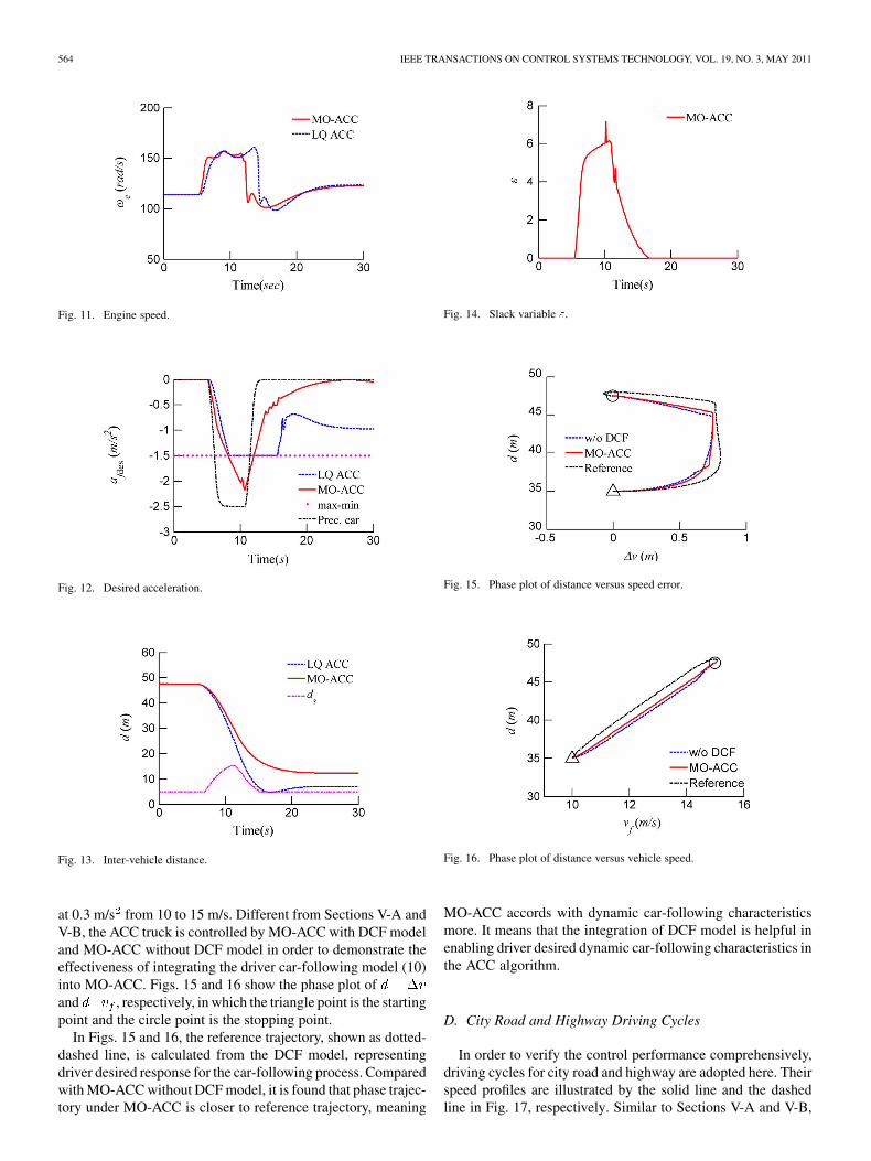
In preceding car’s emergency braking scenario, the precedingcar decelerates at the acceleration of 2.5 m/s from 15 to 1m/s. The ACC truck is controlled to follow it by the MO-ACCand LQACC algorithms, respectively. The results are shown inFigs. 12 and 13.
From Figs. 12 and 13, it is found that due to the constraintscoming from driver longitudinal ride comfort, the LQACCcannot provide enough braking force. The inter-vehiculardistance reaches the safety boundary. And a rear end collisionis possible if the preceding vehicle brakes more urgently. Incontrast, as shown in Fig. 14, the MO-ACC can automaticallyincrease the slack variable to strengthen the braking inputwhen the actual distance approaches the safety boundary. Iteffectively reduces the possibility of rear-end collision.
C. Preceding Vehicle’s Normal Acceleration Scenario
In the preceding vehicle’s normal acceleration scenario, it isassumed that the ACC truck runs at the speed of 10 m/s with apreceding car ahead of it. At 5 s, the preceding car accelerates
564 IEEE TRANSACTIONS ON CONTROL SYSTEMS TECHNOLOGY, VOL. 19, NO. 3, MAY 2011
Fig. 11. Engine speed.
Fig. 12. Desired acceleration.
Fig. 13. Inter-vehicle distance.
at 0.3 m/s from 10 to 15 m/s. Different from Sections V-A andV-B, the ACC truck is controlled by MO-ACC with DCF modeland MO-ACC without DCF model in order to demonstrate theeffectiveness of integrating the driver car-following model (10)into MO-ACC. Figs. 15 and 16 show the phase plot ofand , respectively, in which the triangle point is the startingpoint and the circle point is the stopping point.
In Figs. 15 and 16, the reference trajectory, shown as dotted-dashed line, is calculated from the DCF model, representingdriver desired response for the car-following process. Comparedwith MO-ACC without DCF model, it is found that phase trajec-tory under MO-ACC is closer to reference trajectory, meaning
Fig. 14. Slack variable �.
Fig. 15. Phase plot of distance versus speed error.
Fig. 16. Phase plot of distance versus vehicle speed.
MO-ACC accords with dynamic car-following characteristicsmore. It means that the integration of DCF model is helpful inenabling driver desired dynamic car-following characteristics inthe ACC algorithm.
D. City Road and Highway Driving Cycles
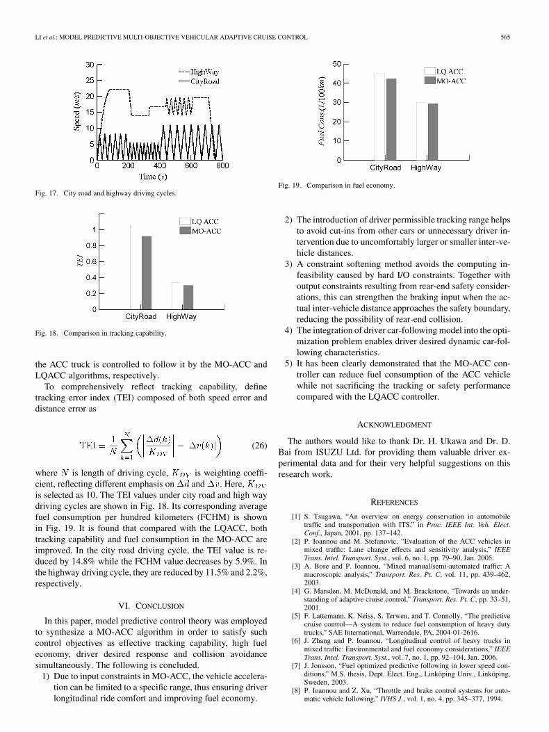
In order to verify the control performance comprehensively,driving cycles for city road and highway are adopted here. Theirspeed profiles are illustrated by the solid line and the dashedline in Fig. 17, respectively. Similar to Sections V-A and V-B,
LI et al.: MODEL PREDICTIVE MULTI-OBJECTIVE VEHICULAR ADAPTIVE CRUISE CONTROL 565
Fig. 17. City road and highway driving cycles.
Fig. 18. Comparison in tracking capability.
the ACC truck is controlled to follow it by the MO-ACC andLQACC algorithms, respectively.
To comprehensively reflect tracking capability, definetracking error index (TEI) composed of both speed error anddistance error as
(26)
where is length of driving cycle, is weighting coeffi-cient, reflecting different emphasis on and . Here,is selected as 10. The TEI values under city road and high waydriving cycles are shown in Fig. 18. Its corresponding averagefuel consumption per hundred kilometers (FCHM) is shownin Fig. 19. It is found that compared with the LQACC, bothtracking capability and fuel consumption in the MO-ACC areimproved. In the city road driving cycle, the TEI value is re-duced by 14.8% while the FCHM value decreases by 5.9%. Inthe highway driving cycle, they are reduced by 11.5% and 2.2%,respectively.
VI. CONCLUSION
In this paper, model predictive control theory was employedto synthesize a MO-ACC algorithm in order to satisfy suchcontrol objectives as effective tracking capability, high fueleconomy, driver desired response and collision avoidancesimultaneously. The following is concluded.
1) Due to input constraints in MO-ACC, the vehicle accelera-tion can be limited to a specific range, thus ensuring driverlongitudinal ride comfort and improving fuel economy.
Fig. 19. Comparison in fuel economy.
2) The introduction of driver permissible tracking range helpsto avoid cut-ins from other cars or unnecessary driver in-tervention due to uncomfortably larger or smaller inter-ve-hicle distances.
3) A constraint softening method avoids the computing in-feasibility caused by hard I/O constraints. Together withoutput constraints resulting from rear-end safety consider-ations, this can strengthen the braking input when the ac-tual inter-vehicle distance approaches the safety boundary,reducing the possibility of rear-end collision.
4) The integration of driver car-following model into the opti-mization problem enables driver desired dynamic car-fol-lowing characteristics.
5) It has been clearly demonstrated that the MO-ACC con-troller can reduce fuel consumption of the ACC vehiclewhile not sacrificing the tracking or safety performancecompared with the LQACC controller.
ACKNOWLEDGMENT
The authors would like to thank Dr. H. Ukawa and Dr. D.Bai from ISUZU Ltd. for providing them valuable driver ex-perimental data and for their very helpful suggestions on thisresearch work.
REFERENCES
[1] S. Tsugawa, “An overview on energy conservation in automobiletraffic and transportation with ITS,” in Proc. IEEE Int. Veh. Elect.Conf., Japan, 2001, pp. 137–142.
[2] P. Ioannou and M. Stefanovic, “Evaluation of the ACC vehicles inmixed traffic: Lane change effects and sensitivity analysis,” IEEETrans. Intel. Transport. Syst., vol. 6, no. 1, pp. 79–90, Jan. 2005.
[3] A. Bose and P. Ioannou, “Mixed manual/semi-automated traffic: Amacroscopic analysis,” Transport. Res. Pt. C, vol. 11, pp. 439–462,2003.
[4] G. Marsden, M. McDonald, and M. Brackstone, “Towards an under-standing of adaptive cruise control,” Transport. Res. Pt. C, pp. 33–51,2001.
[5] F. Lattemann, K. Neiss, S. Terwen, and T. Connolly, “The predictivecruise control—A system to reduce fuel consumption of heavy dutytrucks,” SAE International, Warrendale, PA, 2004-01-2616.
[6] J. Zhang and P. Ioannou, “Longitudinal control of heavy trucks inmixed traffic: Environmental and fuel economy considerations,” IEEETrans. Intel. Transport. Syst., vol. 7, no. 1, pp. 92–104, Jan. 2006.
[7] J. Jonsson, “Fuel optimized predictive following in lower speed con-ditions,” M.S. thesis, Dept. Elect. Eng., Linköping Univ., Linköping,Sweden, 2003.
[8] P. Ioannou and Z. Xu, “Throttle and brake control systems for auto-matic vehicle following,” IVHS J., vol. 1, no. 4, pp. 345–377, 1994.
566 IEEE TRANSACTIONS ON CONTROL SYSTEMS TECHNOLOGY, VOL. 19, NO. 3, MAY 2011
[9] K. Yi and Y. Kwon, “Vehicle-to-vehicle distance and speed controlusing an electronic-vacuum booster,” JASE Rev. vol. 4, pp. 403–412,2001.
[10] M. Persson, F. Botling, E. Hesslow, and R. Johansson, “Stop and gocontroller for adaptive cruise control,” in Proc. IEEE Int. Conf. ControlAppl., 1999, pp. 1692–1697.
[11] A. Higashimata, K. Adachi, T. Hashizume, and S. Tange, “Design of aheadway distance control system for ACC,” J. JSAE Rev., vol. 22, pp.15–22, 2001.
[12] D. Corona, M. Lazar, B. Schutter, and M. Heemels, “A hybrid MPCapproach to the design of a smart adaptive cruise controller,” in Proc.IEEE Int. Conf. Control Appl., Germany, 2006, pp. 231–235.
[13] D. Corona and B. Schutter, “Adaptive cruise control for a SMARTcar: A comparison benchmark for MPC-PWA control methods,” IEEETrans. Control Syst. Technol., vol. 16, no. 2, pp. 365–372, Mar. 2008.
[14] N. Kohut, F. Borrelli, K. Hedrick, A. Lamprecht, J. Lee, C. Lee, andD. Rosario, “Utilization of intelligent transport systems information toincrease fuel economy through engine control,” presented at the ITS,New York, 2008.
[15] V. Bageshwar, W. Garrard, and R. Rajamani, “Model predictive controlof transitional maneuvers for adaptive cruise control vehicles,” IEEETrans. Veh. Technol., vol. 53, no. 5, pp. 365–374, Sep. 2004.
[16] R. Rajamani, Vehicle Dynamics and Control. New York: SpringerVerlag, 2005.
[17] C. Fang and D. Xiao, Process Identification. China: Tsinghua Uni-versity Press, 1988.
[18] M. Brackstone and M. McDonald, “Car-following: a historical review,”Transport. Res. Pt. F, vol. 2, pp. 181–196, 1999.
[19] E. Boer, W. Nicholas, M. Michael, and K. Nobuyuki, “Driver-model-based assessment of behavioral adaptation,” presented at the JSAESpring, Yokohama, Japan, 2005.
[20] L. Zhang, “Driver longitudinal behavior based forward collisionwarning system,” M.S. thesis, Dept. Automot. Eng., Tsinghua Univ.,Tsinghua, China, 2006.
[21] K. Xie, L. Han, and J. Dong, Optimization Method. Tianjing: Tian-jing Univ. Press, 1997.
[22] J. Maciejowski, Predictive Control With Constraints. England:Pearson Education, 2002.
[23] S. Li, “Vehicular multi-objective coordinated adaptive cruise control,”Ph.D. dissertation, Dept. Automot. Eng., Tsinghua Univ., Tsinghua,China, 2009.
Shengbo Li received the M.S. and Ph.D. degreesfrom Tsinghua University, Tsinghua, China, in 2006and 2009, respectively, and the B.Eng. degree fromthe University of Science and Technology, Beijing,China, in 2004.
He is currently a Research Fellow with the Uni-versity of Michigan, Ann Arbor. His active researchinterests include vehicle dynamics and control, driverbehavior, and human factors. He has coauthored overten journal and conference papers and is a coinventoron six patent applications.
Keqiang Li received the M.S. and Ph.D. degreesfrom Chongqing University, Chongqing, China, in1988 and 1995, respectively, and the B.Tech. degreefrom Tsinghua University, Tsinghua, China, in 1985.
He is currently a Professor with the Department ofAutomotive Engineering, Tsinghua University. Hismain areas of research interest include vehicle dy-namics and control for driver assistance systems andhybrid electrical vehicles. He has authored over 90papers and is a coinventor on 12 patents in China andJapan.
Dr. Li has served as a senior member of the Society of Automotive Engineersof China, and on the editorial boards of the International Journal of ITS Re-search and the International Journal of Vehicle Autonomous Systems. He was arecipient of the “Changjiang Scholar Program Professor” title, and several otherawards from public agencies and academic institutions of China.
Rajesh Rajamani received the M.S. and Ph.D. de-grees from the University of California at Berkeley,Berkeley, in 1991 and 1993, respectively, and theB.Tech. degree from the Indian Institute of Tech-nology, Madras, India, in 1989.
He is currently a Professor with the Department ofMechanical Engineering, University of Minnesota,Minneapolis. His active research interests includesensors and control systems for automotive andbiomedical applications. He has authored over75 journal papers and is a coinventor on 7 patent
applications. He is the author of Vehicle Dynamics and Control (SpringerVerlag, 2005).
Dr. Rajamani has served as a Chair of the IEEE Technical Committee onAutomotive Control and on the editorial boards of the IEEE TRANSACTIONS
ON CONTROL SYSTEMS TECHNOLOGY and the IEEE/ASME TRANSACTIONS ON
MECHATRONICS. He was a recipient of the CAREER Award from the NationalScience Foundation, the 2001 Outstanding Paper award from the journal IEEETransactions on Control Systems Technology, the Ralph Teetor Award fromSAE, and the 2007 O. Hugo Schuck Award from the American Automatic Con-trol Council.
Jianqiang Wang received the B.Tech., M.S., andPh.D. degrees from Jilin University of Technology,Jilin, China, in 1994, 1997, and 2002, respectively.
He is currently an Associate Professor with the De-partment of Automotive Engineering, Tsinghua Uni-versity, Tsinghua, China. His active research interestsinclude intelligent vehicles, driving assistance sys-tems and driver behavior. He has authored over 40journal papers and is a coinventor on 20 patent appli-cations.
Dr. Wang has engaged in over ten sponsoredprojects and has received six awards including the “Jilin Province S&TProgress Award” and the “Chinese Automotive Industry S&T Progress Award.”


![Networked Cooperative Distributed Model Predictive Control ...buted model predictive control [8]. In recent years, the research on the distributed predictive control method has developed](https://static.fdocuments.us/doc/165x107/604cfd89a77d0d5d875ad888/networked-cooperative-distributed-model-predictive-control-buted-model-predictive.jpg)


