AlViS Introduction Dipl. Ing. Lubomir Bak Project manager Spirit a.s. [email protected] .
Upload
bharath-chandra-reddyCategory
view
219download
0
8/7/2019 551791819.BAK No Restriction
http://slidepdf.com/reader/full/551791819bak-no-restriction 1/58
Design and Construction of an Autonomous
Ornithopter
by
Zachary John Jackowski
Submitted to the Department of Mechanical Engineeringin partial fulfillment of the requirements for the degree of
Bachelor of Science in Mechanical Engineering
at the
MASSACHUSETTS INSTITUTE OF TECHNOLOGY
June 2009
c Zachary John Jackowski, MMIX. All rights reserved.
The author hereby grants to MIT permission to reproduce anddistribute publicly paper and electronic copies of this thesis document
in whole or in part.
Author . . . . . . . . . . . . . . . . . . . . . . . . . . . . . . . . . . . . . . . . . . . . . . . . . . . . . . . . . . . . . .Department of Mechanical Engineering
May 7, 2009
C e r t i fi e d b y . . . . . . . . . . . . . . . . . . . . . . . . . . . . . . . . . . . . . . . . . . . . . . . . . . . . . . . . . .Russell Louis Tedrake
Assistant ProfessorThesis Supervisor
A c c e p t e d b y . . . . . . . . . . . . . . . . . . . . . . . . . . . . . . . . . . . . . . . . . . . . . . . . . . . . . . . . .John H. Leinhard V
Chairman, Undergraduate Thesis Committee

8/7/2019 551791819.BAK No Restriction
http://slidepdf.com/reader/full/551791819bak-no-restriction 2/58
Design and Construction of an Autonomous Ornithopter
by
Zachary John Jackowski
Submitted to the Department of Mechanical Engineeringon May 7, 2009, in partial fulfillment of the
requirements for the degree of Bachelor of Science in Mechanical Engineering
Abstract
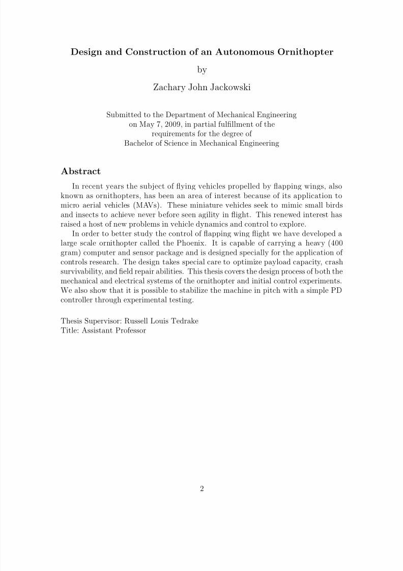
In recent years the subject of flying vehicles propelled by flapping wings, also
known as ornithopters, has been an area of interest because of its application tomicro aerial vehicles (MAVs). These miniature vehicles seek to mimic small birdsand insects to achieve never before seen agility in flight. This renewed interest hasraised a host of new problems in vehicle dynamics and control to explore.
In order to better study the control of flapping wing flight we have developed alarge scale ornithopter called the Phoenix. It is capable of carrying a heavy (400gram) computer and sensor package and is designed specially for the application of controls research. The design takes special care to optimize payload capacity, crashsurvivability, and field repair abilities. This thesis covers the design process of both themechanical and electrical systems of the ornithopter and initial control experiments.We also show that it is possible to stabilize the machine in pitch with a simple PD
controller through experimental testing.
Thesis Supervisor: Russell Louis TedrakeTitle: Assistant Professor
2
8/7/2019 551791819.BAK No Restriction
http://slidepdf.com/reader/full/551791819bak-no-restriction 3/58
Design and Construction of an Autonomous Ornithopter
by
Zachary John Jackowski
Submitted to the Department of Mechanical Engineeringon May 7, 2009, in partial fulfillment of the
requirements for the degree of Bachelor of Science in Mechanical Engineering
Abstract
In recent years the subject of flying vehicles propelled by flapping wings, also
known as ornithopters, has been an area of interest because of its application tomicro aerial vehicles (MAVs). These miniature vehicles seek to mimic small birdsand insects to achieve never before seen agility in flight. This renewed interest hasraised a host of new problems in vehicle dynamics and control to explore.
In order to better study the control of flapping wing flight we have developed alarge scale ornithopter called the Phoenix. It is capable of carrying a heavy (400gram) computer and sensor package and is designed specially for the application of controls research. The design takes special care to optimize payload capacity, crashsurvivability, and field repair abilities. This thesis covers the design process of both themechanical and electrical systems of the ornithopter and initial control experiments.We also show that it is possible to stabilize the machine in pitch with a simple PD
controller through experimental testing.
Thesis Supervisor: Russell Louis TedrakeTitle: Assistant Professor
2

8/7/2019 551791819.BAK No Restriction
http://slidepdf.com/reader/full/551791819bak-no-restriction 4/58
Acknowledgments
I’d like to thank Russ Tedrake, Rick Cory and the other members of the Robot
Locomotion Group not just for the facilitation of this project, but for the much more
important education in the world of research and robotics I received during my two
years on the project. Their support and the environment of the lab have been one
of the biggest influences of my academic career so far and despite my well known
joking cynicism the atmosphere of excitement and progress in the lab has been very
inspirational.
I’d also like to thank my dad and mom for everything they’ve done along the way.
Despite my time spent in endless engineering classes most of the design intuition and
skills I find most valuable have come from years spent working on everything from
flintlock rifles to competition dragsters with my dad. Sometimes in opposition to this,
my mom’s unwavering support has been the most important thing that has kept my
education and research career going in the right direction.
3

8/7/2019 551791819.BAK No Restriction
http://slidepdf.com/reader/full/551791819bak-no-restriction 5/58
Contents
1 Introduction 9
2 Project Purpose 11
3 Related Work 14
4 Project Requirements 16
5 Electronics 18
5.1 Computer . . . . . . . . . . . . . . . . . . . . . . . . . . . . . . . . . 18
5.2 Battery . . . . . . . . . . . . . . . . . . . . . . . . . . . . . . . . . . 19
5.3 Sensors . . . . . . . . . . . . . . . . . . . . . . . . . . . . . . . . . . . 20
5.4 Hardware Interface . . . . . . . . . . . . . . . . . . . . . . . . . . . . 22
5.4.1 Wireless Communications . . . . . . . . . . . . . . . . . . . . 24
6 Wings 26
7 Gearbox 30
7.1 Load Case Development . . . . . . . . . . . . . . . . . . . . . . . . . 30
7.2 Drive Linkage, Wing Joining Gears and Spar Mounts . . . . . . . . . 32
7.3 Motor Selection . . . . . . . . . . . . . . . . . . . . . . . . . . . . . . 34
7.4 Gearbox Frame . . . . . . . . . . . . . . . . . . . . . . . . . . . . . . 38
8 Tail 42
9 Main Frame 45
4
8/7/2019 551791819.BAK No Restriction
http://slidepdf.com/reader/full/551791819bak-no-restriction 6/58
10 Control System 48
11 Testing 50
12 Conclusion 55
5

8/7/2019 551791819.BAK No Restriction
http://slidepdf.com/reader/full/551791819bak-no-restriction 7/58
List of Figures
2-1 The Kestrel ornithopter. . . . . . . . . . . . . . . . . . . . . . . . . . 12
5-1 Two of the computers used in the project. On the left is the Elektra
and on the right is the Gumstix. . . . . . . . . . . . . . . . . . . . . . 19
5-2 The MicroStrain 3DM-GX1 IMU used to sense orientation. . . . . . . 21
5-3 Pololu servo controller board used to convert RS232 output from the
computer to PWM control signals for hobby servos. . . . . . . . . . . 22
5-4 Servo signal multiplexer to switch between remote operator and auto-
matic control. Next to the multiplexer board is the radio receiver in
blue. . . . . . . . . . . . . . . . . . . . . . . . . . . . . . . . . . . . . 23
5-5 Main drive motor speed controller. Converts the PWM control signal
into the appropriate waveform to drive the high current brushless motor. 24
5-6 Block diagram of the overall electronics system configuration. . . . . . 25
6-1 A section of the wing material with the 3M VHB adhesive tape applied. 28
6-2 A frame of high speed video taken of the Kestrel which shows the
amount of wing spar flex in normal flight. . . . . . . . . . . . . . . . 28
6-3 The compliant wing spar end assembly. . . . . . . . . . . . . . . . . . 29
7-1 Side and front view of the Kestrel gearbox. Note the longitudinal
configuration of the reducing gears and the matched linkages on either
side. The shoulder and crank rotate about different axes, plastic ball
joints allow this 3D motion to take place. . . . . . . . . . . . . . . . . 33
6

8/7/2019 551791819.BAK No Restriction
http://slidepdf.com/reader/full/551791819bak-no-restriction 8/58
7-2 Sample yield stress and buckling analysis results from FEA performed
on the linkage components. . . . . . . . . . . . . . . . . . . . . . . . . 34
7-3 Exploded view of the four bar linkage the drives the wing motion.
Notice the planar motion in comparison to the Kestrel’s linkage and
ball bearings at every joint. . . . . . . . . . . . . . . . . . . . . . . . 35
7-4 A sampling of the micro bearings used in the flapping transmission. 36
7-5 An exploded view of the wing shoulder assembly. Pins connect the
delrin spar receptacle to both the driving gear and the drive linkage
rocker. . . . . . . . . . . . . . . . . . . . . . . . . . . . . . . . . . . . 36
7-6 The brushless outrunner motor used in the ornithopter gearbox taken
apart to show its unusual configuration. Notice that the outside can
of the motor rotates rather than the coils inside. . . . . . . . . . . . . 37
7-7 Side view of the complete gearbox showing the motor mounted and the
configuration of the transmission gears. . . . . . . . . . . . . . . . . . 39
7-8 The welded titanium gearbox frame which holds all of the drive compo-
nents together. Bent and welded sheet construction produces a strong,
lightweight, and inexpensive part. . . . . . . . . . . . . . . . . . . . . 40
8-1 The tail section of the Kestrel. The tail uses a clever configuration to
decouple the elevator and rudder actions . . . . . . . . . . . . . . . . 43
8-2 The tail section of the Phoenix. In contrast with the Kestrel the servos
are directly joined in an effort to simplify the mechanism and save weight. 44
9-1 A rendering of the Phoenix in the process of placing all of the compo-
nents for the correct center of gravity. . . . . . . . . . . . . . . . . . . 46
9-2 The main frame of the ornithopter. It is fabricated from a stiff carbon
fiber plate and provides mounting locations for all of the machine’s
subsystems. . . . . . . . . . . . . . . . . . . . . . . . . . . . . . . . . 46
9-3 The completed ornithopter. . . . . . . . . . . . . . . . . . . . . . . . 47
7

8/7/2019 551791819.BAK No Restriction
http://slidepdf.com/reader/full/551791819bak-no-restriction 9/58
11-1 A slice of orientation data taken from flight after initial conditions have
died out. . . . . . . . . . . . . . . . . . . . . . . . . . . . . . . . . . . 51
11-2 Torque from the main drive motor based on current into the speed
controller. Notice the periodic variation at about 4Hz with a high
torque peak on the downstroke and low torque peak on the upstroke. 52
11-3 Power consumed by the main drive motor. Mean power is 147 watts. 53
11-4 Several frames from the video of the first successful semi-autonomous
flight of the Phoenix. The robot maintained steady level flight until
shut off to avoid impacting the building. The author (in blue) is han-
dling the throttle set point and controller switchover while graduate
student John Roberts (green) launches the robot. . . . . . . . . . . . 54
8

8/7/2019 551791819.BAK No Restriction
http://slidepdf.com/reader/full/551791819bak-no-restriction 10/58
Chapter 1
Introduction
Natural fliers like birds and insects have captivated the minds of human inventorsthrough history. The ease and grace with which they take to the air vastly surpasses
the state of the art in aircraft and their control systems.
This is not to say that modern aircraft designs are ineffective, they are excellent
in many respects. Propellers and turbines are very efficient methods of producing
thrust and airfoils efficiently produce lift. A Boeing 747 achieves a dimensionless cost
of transport (energy used divided by weight times distance) of 0.1, equivalent to a
soaring albatross [14], and does it with amazing reliability, but it will never matchthe maneuverability of the albatross.
The problem mirrors legged versus wheeled locomotion well. Wheels provide a
stable, easy to analyze, and very efficient way of getting around with the sacrifice
of a large amount of agility. Legs are notoriously difficult to control and current
implementations are energy inefficient [2] and flapping wing flight parallels this well.
The unsteady fluid dynamics of flapping wings are poorly understood and it’s difficult
to get an ornithopter (the term used henceforth to refer to a flapping wing vehicle)to maneuver as desired.
Interest in the design and control of ornithopters has grown in recent years as
interest has grown in the area of Micro Aerial Vehicles or MAVs. These small flying
machines have struck the imaginations of many as ideal platforms for a variety of tasks
including systems monitoring and surveillance where a swarm of tiny agents would be
9
8/7/2019 551791819.BAK No Restriction
http://slidepdf.com/reader/full/551791819bak-no-restriction 11/58
unobtrusive and have better access to confined areas than larger flying vehicles [6].
This thesis covers two years of work on the Phoenix ornithopter project, a 1.8
meter wingspan flapping wing flying robot, picking up from just after proof of concept
work performed at the lab. From that point on two hardware revisions were produced
of the Phoenix, one in summer 2007 and one in summer 2008. In the time between
these summers flight testing and analysis was performed. Sustained steady level flight
under computer control was finally achieved in August 2008.
10
8/7/2019 551791819.BAK No Restriction
http://slidepdf.com/reader/full/551791819bak-no-restriction 12/58
Chapter 2
Project Purpose
Perhaps the first question that must be asked about the project is what it hasto do with Micro Aerial Vehicles and why the work is a reasonable research direc-
tion, especially because a large ornithopter bears little resemblance to the kinds of
miniature machines many researchers are focused on. While it is true that at a 1.8
meter wingspan the Phoenix isn’t a step toward the resolution of the problems that
currently plague MAV research like energy storage and actuator miniaturization, it is
a big step toward solving the problems that these projects will encounter soon, those
of control. Even though the Phoenix is many times the size of MAVs under develop-ment we conjecture that the problems inherent in stabilizing and coaxing agility out
of them are retained in large part with the scaling up.
Working with a much larger robot allows us to sidestep the problems of minia-
turization and instead work on the problems that interest the Robot Locomotion
Group specifically, those of dynamics and control. Instead of working in series with
researchers attempting to build the miniature machines we are working in parallel
with comparatively easy to build hardware and off the shelf electronics to lay thegroundwork on the dynamics and control work which will be central to the next steps
in these projects. This is not to say that the dynamics will be the same, they may be
as far apart as the differences between how a hawk and bumble bee fly, but the body
of work covering the control of any sort of flapping wing flight is extremely small so
any conclusions reached will be valuable additions as work moves forward.
11
8/7/2019 551791819.BAK No Restriction
http://slidepdf.com/reader/full/551791819bak-no-restriction 13/58
This research is also performed in parallel with fixed wing flight research in the
Robot Locomotion Group’s Agile Flight Project. Rick Cory along with Woody
Hoburg have been making amazing progress in the area of agile fixed wing flight
[3, 8]. Their work in free flight system identification and control over trajectories in-
volving extreme angles of attack focuses on perching maneuvers. This research is both
being applied directly to fixed wing unmanned aerial vehicles [12] and also has the
aim of developing methods and software tools to work with the Phoenix ornithopter
and further improved ornithopters to follow.
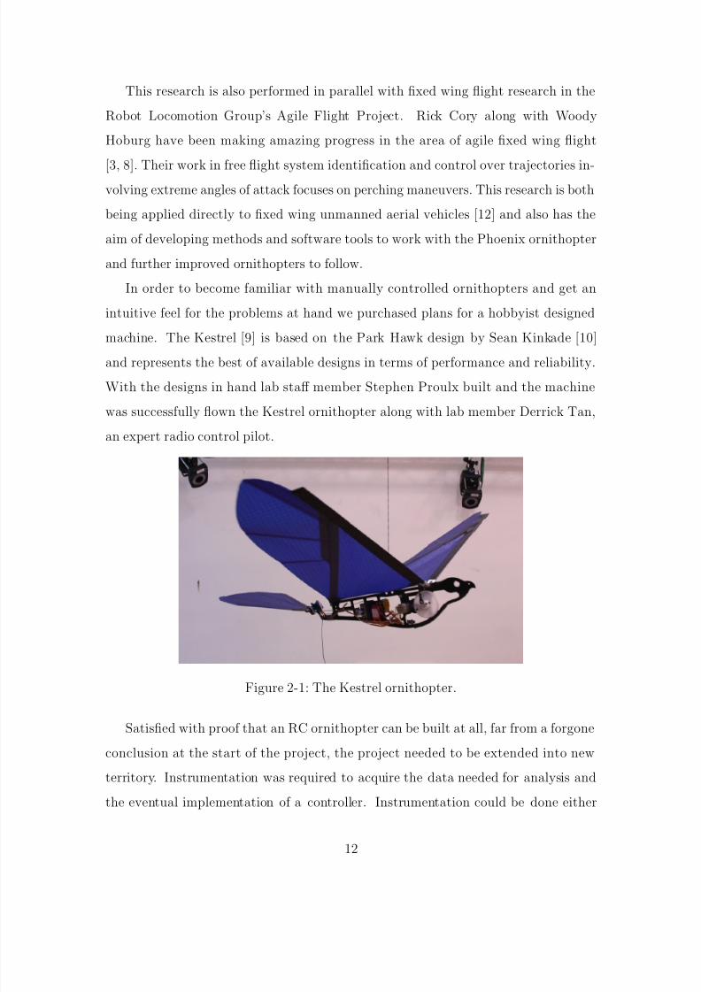
In order to become familiar with manually controlled ornithopters and get an
intuitive feel for the problems at hand we purchased plans for a hobbyist designed
machine. The Kestrel [9] is based on the Park Hawk design by Sean Kinkade [10]
and represents the best of available designs in terms of performance and reliability.
With the designs in hand lab staff member Stephen Proulx built and the machine
was successfully flown the Kestrel ornithopter along with lab member Derrick Tan,
an expert radio control pilot.
Figure 2-1: The Kestrel ornithopter.
Satisfied with proof that an RC ornithopter can be built at all, far from a forgone
conclusion at the start of the project, the project needed to be extended into new
territory. Instrumentation was required to acquire the data needed for analysis and
the eventual implementation of a controller. Instrumentation could be done either
12

8/7/2019 551791819.BAK No Restriction
http://slidepdf.com/reader/full/551791819bak-no-restriction 14/58
onboard with sensors like an inertial measurement unit or offboard with the Vicon
motion capture system at the lab.
The Vicon environment available provides excellent data and is easy to set up,
but is too small to capture free flight data for the 1.17 meter wingspan vehicle with
its capture area of approximately 3x3x2 meters. In order to use it a scaled down
ornithopter would have to built, but this presented large problems at the surface
because we were already using some of the smallest commonly available RC compo-
nents in order keep the weight of the Kestrel low enough to fly well in the first place.
Scaling down would require even smaller servo motors and would completely rule out
the possibility of any onboard control later because of the reduced payload capacity.
The manual flight testing conducted with the Kestrel qualitatively showed it has
very little excess weight capacity which could be used to accommodate a sensor and
computer package. This leads to two options, either make an extremely light and
small sensor package, or increase the payload capacity of the ornithopter to handle
the weight of the sensors commonly used in the lab. A preliminary analysis of the
payload and carrying capacity showed it would be feasible to make an ornithopter
large enough. In addition to the advantage of using a computer and sensors we are
already familiar with a larger vehicle would have slower dynamics which be easier to
analyze and control when the project is advanced. Increased payload to accommodate
the weight would also allow the expansion of the system with the addition of more
sensors further down the line and improved performance if the computer was also
downsized.
13

8/7/2019 551791819.BAK No Restriction
http://slidepdf.com/reader/full/551791819bak-no-restriction 15/58
Chapter 3
Related Work
Ornithopters have been a relatively obscure area of research in comparison tofixed wing aircraft and field of ornithopter design is sparsely populated. Much of the
research done has been performed by hobbyists such as Sean Kinkade. Kinkade is
the designer of a wide range of radio controlled ornithopters both smaller and larger
than the Park Hawk that the Kestrel is based on and holds a patent on the design
[10]. Even though these machines have been designed both the ornithopters and
plans are exceedingly hard to obtain. Both original designs and designs that build on
Kinkade’s that build are in progress in the hobbyist community but very little workhas been published. Ornithopter designs in similar form factors that focus on adding
additional degrees of freedom to the wings have been published [1] in addition to a
variable amplitude wing design produced by the Robot Locomotion Group previously.
An extensive analysis of the wing design used here has been performed with a
motion capture system by Robyn Harmon of the Morpheus Lab at the University
of Maryland which explains many of the aerodynamic properties of this type of or-
nithopter [7]. The Morpheus Lab has also been working with the simple kinds of ornithopter control presented here [13]. Paralleling this work similar results have
been shown by the University of Arizona working with a 74cm wingspan ornithopter
[11]. Both of these projects make use of a very limited onboard computer in order to
be lightweight enough to fly.
James Delaurier’s work forms much of what has been accomplished in larger scale
14

8/7/2019 551791819.BAK No Restriction
http://slidepdf.com/reader/full/551791819bak-no-restriction 16/58
ornithopter design and analysis. A project to build a piloted ornithopter [4] has been
ongoing for many years and as of July 8, 2006 achieved several seconds of sustained
flight [5].
15
8/7/2019 551791819.BAK No Restriction
http://slidepdf.com/reader/full/551791819bak-no-restriction 17/58
Chapter 4
Project Requirements
When examining what is required to build a robot ornithopter a layered systembecomes apparent.
At the base is the mechanical ornithopter system which has the main requirement
of flying acceptably. Acceptable in this most preliminary case is defined as being able
to sustain flight in calm conditions. Key to this is the ability to carry all the additional
weight of the sensors and computer. Branching out from this base requirement are
several secondary requirements. Because this is a controls research platform it can be
expected that the ornithopter will end most of its flights with crashing at least at thebeginning stages, this makes crash survivability of great importance in addition to it
being a reliable machine in less severe conditions. An emphasis is placed on designed
points of failure to isolate damage to parts easily replaced in the field. In addition to
this all of the systems need to be easy to tie into the computer controller.
The sensing and computing equipment which is taken along for the ride with
the mechanical platform is usually considered secondary, but is key to the intended
research use for the ornithopter. In order to measure as much of the ornithopter’sstate as possible to perform the desired system identification and control sensors are
needed. The absolute position of center of mass in space isn’t important at this stage
because it isn’t a factor in the dynamics, however the orientation of the body and the
position of the wings and tail in relation to the body is very important. In addition
to the sensing of this data a computer is required to log and eventually process it into
16

8/7/2019 551791819.BAK No Restriction
http://slidepdf.com/reader/full/551791819bak-no-restriction 18/58
commands to be sent to the actuators. Ideally this computer would have sufficient
computational power to implement advanced control algorithms unlike many small
scale autopilots based on microcontrollers.
Even though the project requirements are pretty straightforward and simple, the
engineering process to realize them required many iterations to develop them into final
specifications which further required design iterations to produce a realization of those
specifications. The design was broken down into several minimally interconnected
sections.
17

8/7/2019 551791819.BAK No Restriction
http://slidepdf.com/reader/full/551791819bak-no-restriction 19/58
Chapter 5
Electronics
While the electronics on the ornithopter aren’t a critical system as far as themechanical function of the machine performs they do make up the one of the most
important specifications for the project, the minimum payload capacity. Because the
rest of the sizing and design of the ornithopter depends on this the weight of the
computer, interface equipment, sensors, and battery must be determined first.
5.1 Computer
The selection of the computer to base the rest of the system on is one of the defining
decisions of the design process because it makes up the largest amount of additional
payload weight. Because the scaling of the robot depends on the payload capacity
needed the computer choice will have a long chain of effects down the design process.
Two main computer options were selected early on, one for its ease of programming,
the other for its light weight.
A PC/104 form factor computer was the initial choice guided by its previous use in
the lab on other robots. The single board Diamond Elektra has an onboard analog to
digital converter, ethernet network interface, x86 processor equivalent to a Pentium 2,
and most importantly complete driver support for the Matlab XPC realtime kernel.
This software hooks in with Simulink and Matlab on a host computer for fast and
user friendly control system development. On the downside, the computer is heavy
18

8/7/2019 551791819.BAK No Restriction
http://slidepdf.com/reader/full/551791819bak-no-restriction 20/58
Figure 5-1: Two of the computers used in the project. On the left is the Elektra andon the right is the Gumstix.
by itself, 106 grams, but on top of that it needs additional IO boards to interface
with the servos and any wireless communication which add even more weight.
In contrast with the Elektra is the Gumstix system, an ARM based computer
which runs the OpenEmbedded Linux distribution. The system is much more com-
pact and lightweight, the set of boards weighs 43.5 grams, includes the necessary IO
equipment to interface with the servos and a wireless networking module. The major
cost in this option is that development for the system is vastly more difficult. The
software development environment has a steep learning curve, the operating system
and drivers are unreliable, and all of the software needs to be written in C.
In the course of development both systems were used, first the Elektra, which the
initial design was based around, and later the Gumstix on the second revision because
of the unmanageable weight of the Elektra system.
5.2 Battery
The battery used is a three cell lithium polymer pack, the standard for high
performance machines like airplanes on this scale because it has the best power and
energy to weight ratios available. Power density is the main concern at the initial
stages of the project because flights aren’t expected to last for long which would make
19

8/7/2019 551791819.BAK No Restriction
http://slidepdf.com/reader/full/551791819bak-no-restriction 21/58
power output the limiting factor for the battery. A lithium polymer battery can be
discharged at up to 10 times its capacity (commonly referred to as 10C) with specially
selected batteries capable of continuous discharge up to 25C which makes it able to
deliver the short bursts of power that the ornithopter needs to flap during short test
flights.
Lithium phosphate batteries produced by A123 were also investigated because
they have similar characteristics but the cell sizes available at the time were too large
to make a suitably lightweight pack at the correct voltage. Since then a smaller series
of cells has become available, the 18650, which matches the application well. Four
cells would produce a pack at 13.2 volts at 156 grams. This works out comparably
to the lithium polymer pack with two important advantages. The cell price of the
lithium phosphate batteries works out to a pack at about half the price of the lithium
polymer pack. In addition to this the lithium phosphate cells are much less sensitive
to overcharging which causes lithium polymer batteries to violently explode. Because
of potential cost and safety advantages of the lithium phosphate cells over the lithium
polymer cells they may be further investigated in the future.
Because the current draw from the motor wasn’t yet known a standard battery,
1200mAh at 11.4V and 93 grams, was chosen for the weight calculation. Eventually
a three cell 2200mAh battery pack was selected for actual use.
5.3 Sensors
Ideally full state information for the ornithopter would be available to the control
system, but because sensors are a significant part of the weight budget only those
of immediate need to the control system envisioned were included. Orientation and
velocity are typically used to describe the state of an aircraft because the body’s
position doesn’t generally play a part in the vehicle dynamics. This of course discounts
environmental effects like wind and obstructions.
The MicroStrain 3DM-GX1 is the standard orientation sensor used by the lab
and is widely used in the field. It’s a fully integrated gyroscope, accelerometer, and
20

8/7/2019 551791819.BAK No Restriction
http://slidepdf.com/reader/full/551791819bak-no-restriction 22/58
magnetometer sensor package that performs the sensor filtering and fusion onboard
and communicates orientation and acceleration over an RS232 data line. It was
chosen as the primary sensor for the ornithopter because of its reliable and accurate
performance in addition to its small and lightweight construction. The sensor package
is fully integrated onto two small boards with all surface mount construction, making
it surprisingly light at 25.8 grams for the amount of equipment packed onto it.
Figure 5-2: The MicroStrain 3DM-GX1 IMU used to sense orientation.
While velocity information is theoretically available from the sensor through the
integration of reported accelerations in practice that method is extremely prone to
drift and a pitot tube or hot wire velocity sensor is a much better sensor for the
application. Both of these could be added at a later point at a small weight cost
but because the very first control experiments would only be using pitch data in
a single-input-single-output fashion the decision to maximize flying performance by
minimizing weight was chosen.
This also applies to the position data that will eventually be needed for au-
tonomous flights over longer distances and involving turns. There are many extremely
lightweight GPS units that can be integrated at a later time for a small weight penalty
once initial performance concerns are worked out.
21

8/7/2019 551791819.BAK No Restriction
http://slidepdf.com/reader/full/551791819bak-no-restriction 23/58
5.4 Hardware Interface
There are three main elements to the control system interface: the servo motor
controller, drive motor controller, and communications to systems offboard the robot.
Conventional hobby servos like those used on model aircraft use a pulse width
modulated signal with a period of about 40hz and a pulse width of between 1 and 2
milliseconds which corresponds to the desired absolute position of the servo’s output
drive. Because the computer system’s main interface is over RS232 serial, a converter
is needed. Serial to PWM converters designed specifically for controlling hobby servos
are widely available because of their widespread application in robotics. For this
project the Pololu Micro Serial Servo Controller was chosen because of its extremely
small size and weight; the smallest available at about one square inch and about
five grams. The device uses a custom programmed Microchip PIC microcontroller
to receive serial data and produce the PWM signal. While a similar device could be
produced custom for the project the advantage over the already extremely small size
and weight of the Pololu controller would be very small.
Figure 5-3: Pololu servo controller board used to convert RS232 output from thecomputer to PWM control signals for hobby servos.
The actual test fights conducted are a combination of radio control and computer
control, both for procedural and safety reasons. While testing different controllers
22

8/7/2019 551791819.BAK No Restriction
http://slidepdf.com/reader/full/551791819bak-no-restriction 24/58
it’s desirable to be able to control the robot via a conventional radio controller, either
in full or just specific channels like the throttle while the computers handles the
control surfaces. It’s also used to guide the robot into initial conditions where it’s
safe to switch over to the computer controller. There are multiplexers designed for
the specific purpose of robot control in which the signal source selected is controlled
by a separate PWM input from the same radio receiver that traditionally controls
the servos. A digital output line is also connected to the control computer so that the
control loop can be initialized correctly once control is switched over. The multiplexer
used on the Phoenix is the RxMux board made by Reactive Technologies which weighs
about 30 grams. Since the time of the original design Pololu has released a new servo
signal multiplexer that would fit this application much better with significantly size
and weight savings over the Reactive Technologies board.
Figure 5-4: Servo signal multiplexer to switch between remote operator and automaticcontrol. Next to the multiplexer board is the radio receiver in blue.
The drive motor controller sits between the serial to PWM servo controller and
the motor and uses that signal to control a high current driver suitable for the powerrequirements of the large motor. This is again a standard radio control airplane part
and a JETI Model Advance 30 brushless motor speed controller was chosen for this
application because of its past use in the lab. The speed controller is designed to
handle 30 amps of current which was considered to be an upper bound of power
required, about 300 watts at the 11.4 volts the battery pack runs at, and weighs 35
23

8/7/2019 551791819.BAK No Restriction
http://slidepdf.com/reader/full/551791819bak-no-restriction 25/58
grams.
Figure 5-5: Main drive motor speed controller. Converts the PWM control signalinto the appropriate waveform to drive the high current brushless motor.
5.4.1 Wireless Communications
The last major piece of interface equipment is on the other side of system, com-
munication between a base station computer and the robot. While a standard 802.11
network link is desired the PC/104 based system running XPC Target doesn’t sup-
port a USB wireless transceiver. This problem can be sidestepped through the use of
a wireless bridge which connects to the wired ethernet on the computer making the
connection transparent to the system. An Asus WL-330g, the smallest device capable
of the job at the time, was used. This allows data to be offloaded and control system
parameters to be changed without hooking an umbilical cable up to the robot.
The fact that 802.11 wireless networking is the widely used standard in retrospect
has led to many unforeseen problems. The extremely high proliferation of wireless
networks in the Stata Center and around the MIT campus results in several access
points overlapping on all channels in most areas. This overlapping coverage produces
interference that causes latency problems and dropped packets from qualitative ex-
perience. While measures can be taken to increase the strength and directionality of
the desired signal it doesn’t seem to make much difference with respect to the prob-
lems experienced. Depending on the fragility of the protocol used results of these
latency issues and dropped packets can range from insignificant to catastrophic, the
best example of this being the communications used by the Simulink XPC system
24

8/7/2019 551791819.BAK No Restriction
http://slidepdf.com/reader/full/551791819bak-no-restriction 26/58
which completely fails in the presence of any dropped packets.
Figure 5-6: Block diagram of the overall electronics system configuration.
25
8/7/2019 551791819.BAK No Restriction
http://slidepdf.com/reader/full/551791819bak-no-restriction 27/58
Chapter 6
Wings
The wing design chosen for use for the Phoenix is a proven design by Sean Kinkadeand is used throughout his line of ornithopter designs which shows that it scales well.
Working from the years of development on this wing design allows the focus of our
project to be on the parts we have more experience in such as the gearbox, electronics,
and controls. The wings have a triangular support structure made from carbon rods.
A main spar runs along the leading edge of the wing and a strut connects from the
rear of the ornithopter’s body to a point near the tip of the main spar. From this
strut there are several smaller carbon rods that project to the edge of the wing whichare somewhat free to move. This results in a fanning motion from the trailing edge of
the wing that produces thrust while the leading edge is flapping up and down which
directly contributes a part of the lift in addition to the conventional lift coming from
airflow over the wing. [7]
Working from the specifications of the Kestrel ornithopter and the new payload
capacity necessary an approximate size for the scaled up wing was found based on
the wing loading. With its 0.22 square meter wing area and overall weight of 395grams the Kestrel has a wing loading of 1.78 kg
m2 . Scaling to a larger machine that
even the size of is known is a pretty difficult proposition, but a few assumptions can
be applied to clean up the situation. The payload fraction, or amount of payload
divided by the overall weight of the ornithoper is assumed to be constant. For the
Kestrel this number is 0.334 with a payload of 132 grams. The 132 gram payload was
26

8/7/2019 551791819.BAK No Restriction
http://slidepdf.com/reader/full/551791819bak-no-restriction 28/58
estimated by looking at the difference between the weights of onboard components like
the batteries as equipped and the maximum weighs allowed (using lithium polymer
batteries vs nickel metal hydride for example). The estimated required payload for the
Phoenix is 400 grams which, using the same payload fraction, comes to a total weight
of 1197 grams. With this weight in order keep the same wing loading as the Kestrel
the Phoenix will need a wing area of 0.672 square meters. By scaling the original
Kestrel wing the desired wingspan comes to about 2 meters. The actual wingspan
used in the design was shortened to 1.8 meters in order to make the ornithopter easier
to handle through the lab with the option left open to increase the wingspan with
longer spars if necessary.
The wings are of similar construction to a modern kite. The fabric used is 1
2oz
polycarbonate coated ripstop polyester which provides excellent strength and resis-
tance against tearing for very little weight. The sections where the wing interfaces
with spars or the ornithopter frame are constructed from Dacron fabric which is glued
to the polyester fabric to form pockets and reinforced sections, for the most part di-
rectly scaled up from the Kestrel’s wing design. Instead of stitching the fabric which
creates stress concentrations in the fabric gluing is the preferred construction method
now. The gluing is done with the application of a very thin double sided tape called
Very Highly Bonding by 3M. The tape is applied with the backing still on to one
piece of fabric and worked into the surface for full contact, then the backing is pulled
away and the mating piece of fabric is applied.
Selecting the correct wing spars for the scaled up version was one one of the larger
engineering leaps of faith because not only do they have to be strong enough to not
break, but the wings rely heavily on their compliance to produce the kinematics that
have been experimentally found to produce the best performance. In order to try
to match the motion of the Kestrel wings with the much larger Phoenix wings the
moment of inertia of the wing spar was scaled linearly with the torque at the shoulder.
This is because in the case of a beam bending due to a moment acting on the end,
the static situation most closely modeling the ornithopter, deflection at all points
grows linearly with the moment applied. The scaling relationship for this moment is
27

8/7/2019 551791819.BAK No Restriction
http://slidepdf.com/reader/full/551791819bak-no-restriction 29/58
Figure 6-1: A section of the wing material with the 3M VHB adhesive tape applied.
obtained in the gearbox design section further on, applied here, leading to the desired
moment of inertia four times greater than that of the spars of the Kestrel.
Figure 6-2: A frame of high speed video taken of the Kestrel which shows the amountof wing spar flex in normal flight.
The insertion ends of the wing spars are a somewhat difficult engineering problem
because they are the point at which the driving torque is exerted. While the sparis easily able to handle the torque, any piece attached to the end to drive the spar
will create a stress concentration that will create a point of failure. In addition to
this the spars need to be able to be removed from the shoulder assembly both for
assembly of the wing and when they break. In order to distribute the loading along a
length of the spar instead of concentrating it at a point an extremely stiff rubber was
28

8/7/2019 551791819.BAK No Restriction
http://slidepdf.com/reader/full/551791819bak-no-restriction 30/58
used to make a threaded connector that screws into a delrin shoulder. This connector
allows the spar to flex and because it is soft it is unable to create a significant stress
concentration, instead relying on a large area of lower force to exert the torque on
the spar.
Figure 6-3: The compliant wing spar end assembly.
29
8/7/2019 551791819.BAK No Restriction
http://slidepdf.com/reader/full/551791819bak-no-restriction 31/58
Chapter 7
Gearbox
The most critical part of the ornithopter is the drive mechanism the converts theelectric power from the battery to the flapping motion of the wings. This system is
the most complex to design and fabricate because it must withstand very large forces
which reverse direction several times a second while at the same time being extremely
light and durable. Because of the loads it must be made from metal which makes it
beneficial to perform careful analysis and trim as much weight as possible.
The drive system can be further broken down into four sections, the electric motor,
a gear reduction stage, a linkage to convert the high torque rotation into a reciprocat-ing motion, and the connection to the wing spars. While a highly integrated design
is needed in order to maximize the power to weight ratio, the analysis of these parts
breaks down well.
7.1 Load Case Development
In order to figure out what loads the gearbox needs to be designed for the torques
to be exerted at the wing shoulders need to be known. While a relationship for
scaling the torque from the Kestrel ornithopter can be created, the actual torques on
the Kestrel need to known too. Because the gear ratios and and motor characteristics
are known these torques can be found by measuring the current through the electric
motor and calculating the torques at each point in the transmission to the wings.
30

8/7/2019 551791819.BAK No Restriction
http://slidepdf.com/reader/full/551791819bak-no-restriction 32/58
With the ornithopter frame fixed a shunt resistor was used to measure the max-
imum current at full throttle through the brushed DC motor that flaps the wings.
This represents the maximum loading seen by the transmission. An oscilloscope was
used to measure the voltage across the resistor over time along with the voltage across
the motor. With this data it was found that the maximum torque at the motor is
0.00832 Newton-meters and that the wings flap at 6hz in the conditions during mea-
surement. This torque at the motor is translated through the 97.8:1 ratio gearbox
and the flapping linkage to produce 4.43 Newton-meters at the shoulder.
With the torque at the shoulder of the Kestrel and the new wingspan needed by
the Phoenix the one piece that remains is the scaling relationship between wingspan
and torque at the shoulder. This is accomplished with a relatively simple analysis.
The torque at the shoulder is the product of the distance to the center of pressure
(moment arm) times the force produced by the pressure on the wing concentrated
at that point. Because the wing loading is being fixed for this scaling process and
the wings are roughly square the force increases with the square of the wingspan.
In addition to this the distance to the center of pressure increases linearly with the
wingspan as long as the wings remain loaded in a similar fashion along their span.
This suggests that the torque on the shoulder will grow with the cube of the wingspan.
The new design calls for a wingspan 1.56 times longer than that of the Kestrel and
so the shoulder torque is expected to be 3.79 times higher or 7.78 Newton-meters.
The rate at which the wings need to be flapped is also important to selecting
gearbox components. While exact data to base this on isn’t available a video of a
similarly scaled ornithopter based on Kinkade’s design was found which the flapping
frequency could be roughly estimated from. Compared to the Kestrel known to flap
at 6Hz the ornithopter in the video was judged to flap at about 4Hz, roughly in line
with an inverse scaling of flapping frequency with wingspan.
31

8/7/2019 551791819.BAK No Restriction
http://slidepdf.com/reader/full/551791819bak-no-restriction 33/58
7.2 Drive Linkage, Wing Joining Gears and Spar
Mounts
In order for the forces on the wings to balance each other out to produce onlythrust and lift rather a rolling and yawing moment the wings need to move together
in the same motion. This can be accomplished in a couple different ways, either by
having a second, opposite four bar linkage which is the strategy used on the Kestrel,
or with a set of gears that slave the motion of one wing to the other similar to the
design in Kinkade’s patent [10].
In the case of the Kestrel it made sense to have two separate linkages because the
lightly loaded gearbox was able to be built directly into the fiberglass frame of the
ornithopter and was configured longitudinally so setting up two linkages that don’t
interfere with each other is relatively easy. Combined with the fact that they don’t
need to be very strong because of the small scale making two linkages from lightweight
and cheap materials is the natural choice. One major downside to the configuration
is that the rotation of the crank and wing are on different axes which means the links
need to have additional degrees of freedom to accommodate the 3D motion. This is
accomplished with plastic ball joints that are common to model airplanes but creates
a major source of broken parts in practice because the joints are not designed for such
loads.
With the vastly increased load in the Phoenix gearbox a different strategy is
required. The linkage movement must at very least be kept in plane so that proper
bearings can be used at the joints instead of ball joints, this means that the linkage
must be longitudinal which in turn means that having two opposing linkages is much
harder to make work. Luckily slaving one of the wings to the other is also an option.
By putting gear teeth on the shoulders they can be made to turn with each other with
very little extra weight over just moving one wing. With one linkage driving both
wings at the same time the loads on it are slightly more than doubled, but since the
motion is in plane the problem is reduced to a relatively simple problem of selecting
suitable bearings and designing the links to be lightweight and strong in the right
32

8/7/2019 551791819.BAK No Restriction
http://slidepdf.com/reader/full/551791819bak-no-restriction 34/58
Figure 7-1: Side and front view of the Kestrel gearbox. Note the longitudinal config-uration of the reducing gears and the matched linkages on either side. The shoulderand crank rotate about different axes, plastic ball joints allow this 3D motion to takeplace.
directions.
The linkage was designed to match the wing trajectory of the Kestrel with the wing
lifting 30 degrees above the horizontal and 20 degrees below. Flat links constructed
from titanium allow them to be designed to be strongest in the directions that matterand extremely lightweight overall. The geometry of the linkage was determined using
the Solidworks COSMOSMotion package and then the links were optimized using
COSMOSMotion FEA. The links were also analyzed for buckling because their flat
structure is very susceptible to it, the load factor of 8.3 predicts that buckling will
not occur.
The wing shoulders have three functions, forming the second fixed point of the
main drive linkage, driving one wing to match the motion of the other, and providing
an attachment point for the wing spars. Both wing shoulders rotate on titanium
shafts supported by miniature ball bearings. These bearings are commonly used in
small machinery, most notably model cars, and are available cheaply in almost any
size, these coming from Boca Bearing. The miniature bearings are lightweight and
small allowing the overall gearbox size to be kept to a minimum.
33

8/7/2019 551791819.BAK No Restriction
http://slidepdf.com/reader/full/551791819bak-no-restriction 35/58
Figure 7-2: Sample yield stress and buckling analysis results from FEA performed onthe linkage components.
The shoulder piece itself is machined delrin and has a threaded end to accept
the screw in spar discussed in the wing section. The threaded wing spar is essential
because it allows the spars to be quickly changed out when they break and allows
for the compliant rubber of the spar end to mate with the shoulder which must bemuch more rigid. A set of pins join the delrin piece to the aluminum gear that drives
the other wing in addition to the rocker link that drives both wings. The gears that
connect the wings were selected using the Lewis formula for gear tooth strength to
find the the most lightweight gears that fit the form factor of the gearbox. Stock
gears were ordered and waterjetted to the desired shape so that the precise gear teeth
wouldn’t have to be machined.
7.3 Motor Selection
The main drive motor is one of the most important parts to be selected because
it makes up one of the major weight components of the drive system. The highest
power density possible is desirable for obvious reasons, but second to that is a high
34

8/7/2019 551791819.BAK No Restriction
http://slidepdf.com/reader/full/551791819bak-no-restriction 36/58
Figure 7-3: Exploded view of the four bar linkage the drives the wing motion. Noticethe planar motion in comparison to the Kestrel’s linkage and ball bearings at every
joint.
torque density. This is because gear reductions require both additional weight and
space in the transmission. The gears need to be able to handle large torques so
they also must be strong and hence large and heavy. Several types of miniature high
performance motors are available for model airplanes but one in particular sticks
out for this application, the brushless outrunner, which is primarily used in direct
propeller drive configurations because of the high torques supported.
A brushless outrunner motor is essentially an inside out version of the conventionalbrushless motor, instead of the coils being placed around an internal rotating magnet
assembly the coils are wound around a stationary internal post and the magnets are
mounted on the outside motor housing which is free to rotate, shown in figure 7-6.
This puts the magnets that the electromagnetic force created by the coils acts on as
35

8/7/2019 551791819.BAK No Restriction
http://slidepdf.com/reader/full/551791819bak-no-restriction 37/58
Figure 7-4: A sampling of the micro bearings used in the flapping transmission.
Figure 7-5: An exploded view of the wing shoulder assembly. Pins connect the delrin
spar receptacle to both the driving gear and the drive linkage rocker.
far away from the axis of rotation as possible. This creates the largest amount of
torque possible in the space constraints of the motor.
The two outputs from the motor and gear reduction system are already known,
the torque transmitted down through the drive linkage becomes 17.7 Newton-meters
and the desired speed of 4hz becomes 240RPM. Sadly this does not fix the variables
enough to select a motor or design a gearbox right off the bat because a wide range
of gear ratios and motor windings are available. Rather than simply fixing a design
parameter with no basis to proceed, some reasoning about the system was done.
Because of the large torque required at the transmission output a steep gear
reduction will be required along with large strong gears in the stage close to the
output. A gearbox with two reduction stages of the maximum possible ratio was
36

8/7/2019 551791819.BAK No Restriction
http://slidepdf.com/reader/full/551791819bak-no-restriction 38/58
Figure 7-6: The brushless outrunner motor used in the ornithopter gearbox takenapart to show its unusual configuration. Notice that the outside can of the motor
rotates rather than the coils inside.
designed as a starting point. In this case the maximum reduction at each stage was
limited by the strength of the gear teeth, what was kept in stock by the supplier,
and what could be packaged feasibly into a transmission. At the end a maximum of
a 24:1 reduction was achieved which made motor selection very easy. The 240RPM
output shaft speed through the 24:1 reduction becomes a target of 5760RPM at the
motor shaft. At the maximum voltage across the motor of the 11.4 Volts of the three
cell LiPo pack the desired motor speed constant comes out to 505 RPM V
.
The electric motor speed constant is inversely proportional to the motor’s torque
constant, a measure of the amount of torque produced per unit current. Because
of this relationship it makes sense that the small lightweight motors desired for this
application will have high speed constants. Windings available on even the the highest
37
8/7/2019 551791819.BAK No Restriction
http://slidepdf.com/reader/full/551791819bak-no-restriction 39/58
torque motors suitable start well above this speed constant because of their inability
to produce a large amount of torque in such a small space. The law of conservation
of energy when applied to this case shows that for the same energy output the speed
of the motor must increase if the torque produced decreases.
With these specifications the field of possible motors became very small. The se-
lection of windings available in the brushless outrunner motors used in model aircraft
is quite limited because of the specialized application but a motor that fit the desired
specifications closely enough was found. The PJS 3D 1200 motor, convienently used
in previous experiments in the lab has a speed constant of 848 RPM V
and a torque con-
stant of 0.01126NmA
. The expected torque required at the motor shaft of 0.7375Nm
requires 65A of current through the motor. While this current seems too high the
options to lower it, either by adding a gearbox stage or using a heavier motor are
as unpalatable as handling the high current. This decision was one of the major
engineering compromises of the project but the stacked safety factors in the gearbox
loading and conservative scaling estimates used so far make the predicted loadings
especially brutal at this stage. The decision to go with the PJS 3D 1200 motor and
deal with the consequences of high current was made with the option of using a larger
motor if testing indicates the necessity.
7.4 Gearbox Frame
The gearbox frame is a component whose performance, not just existence, is crit-
ical to every function of the gearbox. The distance between the gears and hence the
quality of their meshing depends on the accurate construction and stiffness of the
frame. The quality of the gear mesh is of utmost importance because the flapping
motion puts periodically reversing loads on the gears and backlash in that case leads
to very fast tooth destruction in addition to sloppy wing motion at the highest and
lowest parts of the stroke. The pursuit of accuracy and stiffness can quickly lead to
a very heavy and expensive construction.
In order to make the frame as lightweight as possible a titanium sheet design was
38

8/7/2019 551791819.BAK No Restriction
http://slidepdf.com/reader/full/551791819bak-no-restriction 40/58
Figure 7-7: Side view of the complete gearbox showing the motor mounted and the
configuration of the transmission gears.
chosen. The process of designing a complex frame in CAD, cutting it out with a CNC
waterjet cutter, then bending and welding the structure together is very inexpensive
and fast because little time is spent machining large amounts of material away. By
paying careful attention to the design of box and truss structures and how they are
bent from the parent sheet surprising stiffness can be achieved and with the addition
of tabs that guide assembly and welding the entire process is very fast.
The key to making the process come together is welding the individual pieces
together. In order to make the strongest and cleanest welds the Tungsten Inert
Gas (TIG) process is used. This welding process relies heavily on the skill of the
operator to guide the torch and apply the right amount of heat to the part in the
form of an arc between a tungsten electrode and the base metal inside an inert
39
8/7/2019 551791819.BAK No Restriction
http://slidepdf.com/reader/full/551791819bak-no-restriction 41/58
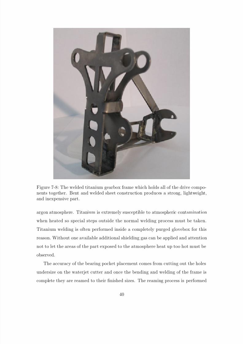
Figure 7-8: The welded titanium gearbox frame which holds all of the drive compo-nents together. Bent and welded sheet construction produces a strong, lightweight,and inexpensive part.
argon atmosphere. Titanium is extremely susceptible to atmospheric contamination
when heated so special steps outside the normal welding process must be taken.
Titanium welding is often performed inside a completely purged glovebox for this
reason. Without one available additional shielding gas can be applied and attention
not to let the areas of the part exposed to the atmosphere heat up too hot must be
observed.
The accuracy of the bearing pocket placement comes from cutting out the holes
undersize on the waterjet cutter and once the bending and welding of the frame is
complete they are reamed to their finished sizes. The reaming process is performed
40

8/7/2019 551791819.BAK No Restriction
http://slidepdf.com/reader/full/551791819bak-no-restriction 42/58
with the frame mounted in the vise of a milling machine, by using the machine’s table
to move the part to the correct hole locations they can be machined accurate to less
than a thousandth of an inch.
When finished the entire frame weighs a total of 58.1 grams and stands up to both
the high internal forces of the gearbox and large amounts of external abuse, usually
from impacts to the ground during crashes. Because large shock loads are expected
from frequent crashes a protective face plate is attached to the main frame by several
screws. Made from much cheaper thin fiberglass laminate it’s intended to flex and
absorb the shocks and break instead of the main frame breaking. Multiple faceplates
can be kept on hand during testing sessions and replaced quickly whereas the main
frame is cut from much more expensive material and would take hours in the lab to
transplant.
41

8/7/2019 551791819.BAK No Restriction
http://slidepdf.com/reader/full/551791819bak-no-restriction 43/58
Chapter 8
Tail
The tail section of the ornithopter is responsible for both of the controllable degreesof freedom aside from the ability to throttle the drive motor. The tail of the Kestrel
is set up with one servo directly connected to the tail at an angle and another further
up the body which rocks it via a linkage. Mounting the rudder servo at an angle is
important because with a single control surface the elevator and rudder are naturally
coupled, moving the rudder servo makes the tail also move in the vertical direction
unless it’s at zero angle where it doesn’t have any control authority anyway. With
the tail at an angle to the rudder servo it allows the servo to held into the zeroangle position with respect to the ornithopter body and while the tail stays near
the trimmed position for horizontal flight. This causes the tail to move in a bowl
shaped trajectory decoupled from the elevator action and is much easier to control
by a human pilot. It does not solve the problem when the elevator servo moves the
tail out of the trimmed horizontal position, but being able to exploit that is a big
advantage where it applies.
A second point to make about the Kestrel tail is that the linkage for the elevatorservo appears to be unnecessary but serves two important purposes. First is that the
servo range of motion is much larger than what is necessary for the tail. By using a
linkage not only does the range of motion get reduced but the mechanical advantage
allows a smaller servo to be used. In addition to this, the servo, a major point of
weight on the ornithopter, is moved forward in the frame. While not obviously an
42

8/7/2019 551791819.BAK No Restriction
http://slidepdf.com/reader/full/551791819bak-no-restriction 44/58
Figure 8-1: The tail section of the Kestrel. The tail uses a clever configuration todecouple the elevator and rudder actions
issue it becomes important once the center of gravity must be placed because the
frame ends up rear-heavy.
The tail of the Phoenix is designed with computer control in mind and so doesn’t
use the configuration the Kestrel exploits to make human control easier, but it does
use the same tail fan design. The servos are directly joined to each other so that
as little weight is spent on linkage and mounting as possible, again using lightweight
welded titanium construction. At a glance it can be seen that the tail cannot follow the
same path as the Kestrel tail, but it should be able to act similarly aerodynamically.
Because of the large surface area of the tail and the fact that tail is attached directly
at the servos output horns very high torque HiTec 5995TG servos with titanium
gearsets were chosen. The high strength gears are much less likely to be damaged in
the event of a crash that impacts on the tail and come at a slight weight savings over
lower torque servos with a steel gearset.
43

8/7/2019 551791819.BAK No Restriction
http://slidepdf.com/reader/full/551791819bak-no-restriction 45/58
Figure 8-2: The tail section of the Phoenix. In contrast with the Kestrel the servosare directly joined in an effort to simplify the mechanism and save weight.
44

8/7/2019 551791819.BAK No Restriction
http://slidepdf.com/reader/full/551791819bak-no-restriction 46/58
Chapter 9
Main Frame
The main frame of the ornithopter is a surprisingly simple component from adesign standpoint. Because the flapping mechanism is contained fully within the
gearbox frame the main frame of the machine serves mainly to provide mounting
locations for the rear wing mounts, electronic components, battery, and tail assembly.
There are two directions to go with the frame design, either a single flat plate which
relies on its own thickness for stiffness, or a three dimensional design made from much
thinner material that gets its stiffness from the truss-like structure.
If the frame had to be very stiff the second option would make for a much lighterand stronger option, but in this case the frame really doesn’t have to be very stiff
in all directions. The rear wing mount actually holds the frame from flexing in the
direction a sheet would be most weak because the wing spars form a very large and
stiff triangle. What this amounts to is that while the more complicated structure is
often the higher stiffness and lower weight option it doesn’t come with much advantage
in this case. The flat frame is vastly easier to design and fabricate and may even be
lighter.Because the frame is really just a collection of mounting locations for the rest of
the components it’s relatively easy to design. The one major specification that must
be paid attention to is the location of the center of gravity. Because the data needed to
work out the correct location theoretically isn’t available this was also scaled up from
the Kestrel where the location was experimentally determined from flight testing to
45
8/7/2019 551791819.BAK No Restriction
http://slidepdf.com/reader/full/551791819bak-no-restriction 47/58
be about 4 inches behind the main wing spar. If this is scaled linearly with wingspan
the desired center of gravity should be about 6 inches behind the main spar.
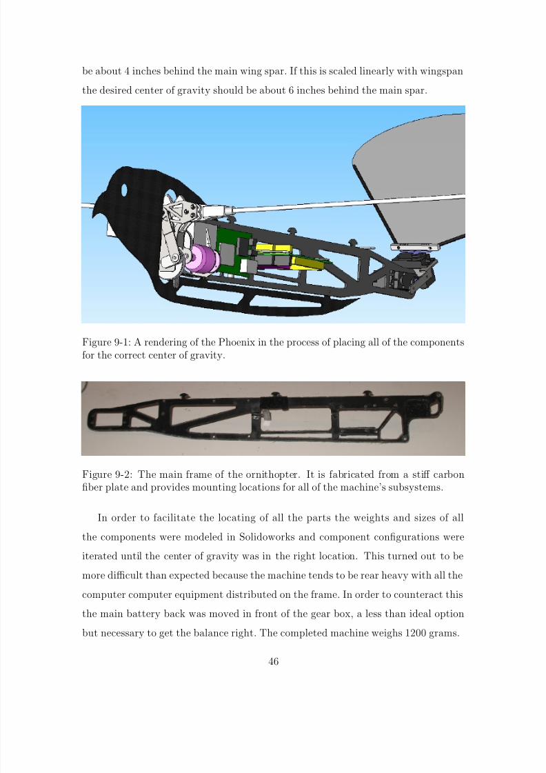
Figure 9-1: A rendering of the Phoenix in the process of placing all of the componentsfor the correct center of gravity.
Figure 9-2: The main frame of the ornithopter. It is fabricated from a stiff carbonfiber plate and provides mounting locations for all of the machine’s subsystems.
In order to facilitate the locating of all the parts the weights and sizes of all
the components were modeled in Solidoworks and component configurations wereiterated until the center of gravity was in the right location. This turned out to be
more difficult than expected because the machine tends to be rear heavy with all the
computer computer equipment distributed on the frame. In order to counteract this
the main battery back was moved in front of the gear box, a less than ideal option
but necessary to get the balance right. The completed machine weighs 1200 grams.
46
8/7/2019 551791819.BAK No Restriction
http://slidepdf.com/reader/full/551791819bak-no-restriction 48/58
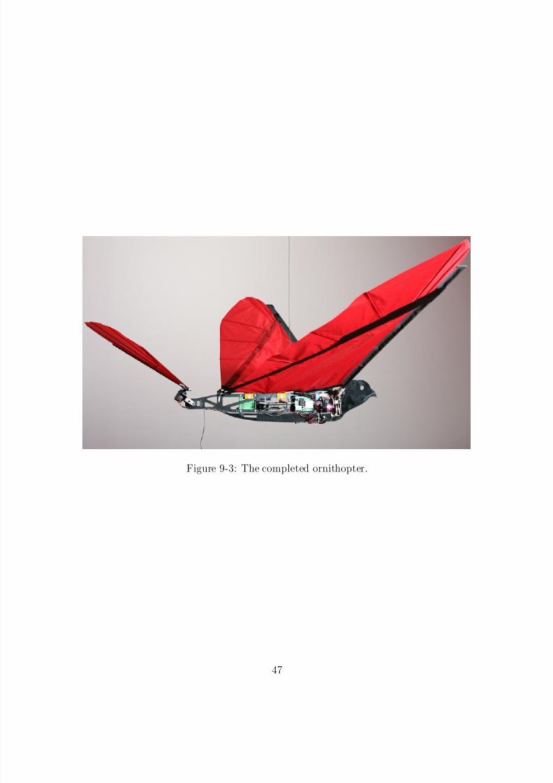
Figure 9-3: The completed ornithopter.
47
8/7/2019 551791819.BAK No Restriction
http://slidepdf.com/reader/full/551791819bak-no-restriction 49/58
Chapter 10
Control System
For the very first flights a PD control was selected for several reasons. First becauseof its widespread application in conventional aircraft autopilots, second because it’s
very simple to establish reasonable starting gains and tune by hand. The proportional
and derivative action is easy to visualize and intuitively understand which is very
important in this case where making as few tests as possible is desired and catastrophic
failure isn’t. Applying PD control to pitch was the first step taken because the other
degrees of freedom are relatively passively stable and pilots had little luck controlling
the ornithopter in pitch themselves. It isn’t obvious that a simple PD control shouldwork with a an ornitopter because of the vehicle’s periodic dynamics from flapping.
One way of looking at the situation is that the controller needs respond to larger
changes in pitch rather than the fast motions due to flapping. In order to accomplish
this the time constant of the controller can be adjusted so that the response to fast
changes in pitch is minimized.
The control system used on the successful flights so far is written in C and runs
on the Gumstix computer at 40Hz. 40Hz is the target update rate because it’s themaximum that the servos can take commands since the frequency of their variable
duty cycle pulses is 40Hz. The pitch and derivative of the pitch come directly from
the inertial measurement unit and do not undergo further filtering. In tests so for the
desired pitch has been set to a constant value approximating what has been seen in
manual flights but this can easily be changed as progress is made.
48

8/7/2019 551791819.BAK No Restriction
http://slidepdf.com/reader/full/551791819bak-no-restriction 50/58
Controlling yaw has not been implemented yet and will require a somewhat more
clever strategy of servo control because the area of the tail presented to the airflow
changes with the position of the elevator servo.
A proportional control on the throttle with altitude as an input has been at-
tempted. The reasoning behind this isn’t full altitude control but to enhance the
level flight by bumping up the throttle a little bit when the ornithopter experiences
a drop in altitude. A sonar range sensor was added to the Phoenix to sense altitude
but the data has been too unreliable to hand control of the throttle over to the con-
troller because of the sensor’s inherent unreliability and the sine errors introduced by
the robot pitching and rolling that must be accounted for. An alternative being in-
vestigated is an extremely sensitive atmospheric pressure sensor in combination with
acceleration data from the IMU.
49

8/7/2019 551791819.BAK No Restriction
http://slidepdf.com/reader/full/551791819bak-no-restriction 51/58
Chapter 11
Testing
Many test flights were conducted with the finished Phoenix ornithopter, first withan equivalent weight and distribution payload under manual control to determine
whether the machine would actually be able to fly. Initial tests showed that sustained
flight was possible but the robot was exceedingly difficult to control and quickly
crashed. Later tests with a PD control on the elevator to stabilize pitch qualitatively
showed promise but difficulties with gearbox and wing spar reliability plagued the
testing process.
This process of breaking things during testing is an essential part of the designprocess and leaps of progress were made during this time in tracking down problems
and implementing design solutions to them. Parts of the gearbox like the connection
between the final rocker link and the shoulder were a common point of failure and
received stopgap design revisions until enough changes accumulated for a full design
iteration of the machine. Changes were incorporated into the gearbox design, the
electronics package switched over to the much lighter Gumstix based system, and the
frame was reconfigured to balance the new weight distribution properly.This second revision Phoenix took its first successful semi-autonomous flight on
August 18, 2008 by traveling about 30 yards in steady, level flight before being shut
down manually to avoid hitting MIT’s Building 18. A PD control stabilizing pitch
was applied to the elevator with the throttle set at a fixed point by a remote control
operator. The throttle setting was taken from a successful manual flight. The con-
50

8/7/2019 551791819.BAK No Restriction
http://slidepdf.com/reader/full/551791819bak-no-restriction 52/58
troller gains and pitch set point were initially set to a response that seemed to mimic
a human pilot and tuned over the course of several tests. At the end of the flight
flapping power is shut off and the wings passively enter a high dihedral which causes
it to quickly glide to the ground while maintaining roll and pitch stability.
Steady state flight data from one of the successful test is shown below, note that
the length of time is only about two seconds because the section containing initial
conditions is excluded and the area used for testing is small. Longer tests are planned
but have not been conducted yet. The data shown covers nine wing beats.
Figure 11-1: A slice of orientation data taken from flight after initial conditions havedied out.
The graph of orientation shows pitch maintained with small variations, most likely
caused by environmental conditions and the action of the wings flapping. Both roll
and yaw are uncontrolled but are expected to be somewhat passively stable. The
trend in roll shown in the data seems likely to be caused by a difference between thewings such as a weakened spar or out of trim tail.
The torque plot in figure 11-2 is based on current into the speed controller as
measured over a current sense resistor. It shows peak torques in the 0.35 Newton-
meter range which is about half the maximum predicted. The peak torque seen
here isn’t the peak torque that can be produced however, because the throttle was
51

8/7/2019 551791819.BAK No Restriction
http://slidepdf.com/reader/full/551791819bak-no-restriction 53/58
Figure 11-2: Torque from the main drive motor based on current into the speedcontroller. Notice the periodic variation at about 4Hz with a high torque peak on thedownstroke and low torque peak on the upstroke.
set at about 70% of maximum for the steady level flight. Two factors complicate
measurement above this point. First is the speed controller is only rated for 30
amperes so going above this level results in the speed controller shutting down. Second
is that throttle settings near maximum excite a second mode in the motion of thewing spars and sets up a standing wave instead the desired flapping motion. Both of
these problems will be subject of further invesigation.
Because both current and voltage are measured it is simple to look at the power
it takes for the ornithopter to fly. While efficiency isn’t an immediate goal it’s obvi-
ous that the current realization of the ornithopter and its controller is an extremely
inefficient way to fly. An estimated forward velocity of about 4 ms
based on total time
of flight and distance covered combined with a vehicle weight of 1.2Kg shows a veryrough unitless cost of transport of about 30.
52

8/7/2019 551791819.BAK No Restriction
http://slidepdf.com/reader/full/551791819bak-no-restriction 54/58
Figure 11-3: Power consumed by the main drive motor. Mean power is 147 watts.
53

8/7/2019 551791819.BAK No Restriction
http://slidepdf.com/reader/full/551791819bak-no-restriction 55/58
Figure 11-4: Several frames from the video of the first successful semi-autonomousflight of the Phoenix. The robot maintained steady level flight until shut off to avoidimpacting the building. The author (in blue) is handling the throttle set point andcontroller switchover while graduate student John Roberts (green) launches the robot.
54

8/7/2019 551791819.BAK No Restriction
http://slidepdf.com/reader/full/551791819bak-no-restriction 56/58
Chapter 12
Conclusion
In this paper the case for the construction of a large scale ornithopter suitable forcontrol systems research is motivated. Performance and weight constraints imposed
by the computers and sensors desired onboard make it difficult to work with the
smaller platforms currently available, let alone micro UAVs currently in development.
In order to work with the dynamics and controls of a flapping wing flying vehicle
while these future targets are currently in development a scaled up version has been
designed and constructed. With its larger payload capacity it’s capable of carrying a
fully equipped computer and high-end inertial measurement unit with the option of future additions of GPS or other more exotic sensors.
The ornithopter was designed from the ground up with the needs of research in
mind. All components have been designed to be as lightweight and high performance
as possible so as to maximize payload capacity and are intended to fail in predicable
and field repairable ways. Examples of this are the screw in wing spars and replaceable
face plates. In addition to this all parts of the ornithopter are simple and inexpensive
to fabricate and assemble.Manual and initial autonomous flight tests have been conducted and show that
the ornithopter is capable of sustained flight with a full load of electronics and can
be stabilized by simple controllers in common use in aircraft. Flight tests have also
shown that the planned points of failure work as expected and allow repairs to be
quickly accomplished in the field.
55

8/7/2019 551791819.BAK No Restriction
http://slidepdf.com/reader/full/551791819bak-no-restriction 57/58
Bibliography
[1] Nathan Chronister. Ornithopter with independently controlled wings. US Patent11147044, June 7, 2005.
[2] Steven H. Collins, Andy Ruina, Russ Tedrake, and Martijn Wisse. Efficientbipedal robots based on passive-dynamic walkers. Science, 307:1082–1085, Feb2005.
[3] Rick E. Cory. Perching with fixed wings. Master’s thesis, Massachusetts Instituteof Technology, 2008.
[4] J.D. DeLaurier. The development and testing of a full-scale piloted ornithopter.Canadian Aeronautics and Space Journal , June 1999.
[5] J.D. DeLaurier. Ornithopter report update. http://ornithopter.net/Publications/OrnithopterReportUpdate19July2006.pdf , July 19, 2006.
[6] Michael H. Dickinson, Fritz-Olaf Lehmann, and Sanjay P. Sane. Wing rotationand the aerodynamic basis of insect flight. Science, 284:1954–60, June 1999.
[7] Robyn Lynn Harmon. Aerodynamic modeling of a flapping membrane wing usingmotion tracking experiments. Master’s thesis, University of Maryland, 2008.
[8] Warren Hoburg and Russ Tedrake. System identification of post stall aero-dynamics for UAV perching. In Proceedings of the AIAA Infotech@AerospaceConference, Seattle, WA, April 2009.
[9] Kestrel ornithopter at r&r model aircraft. http://www.randrmodelaircraft.com /Kestrel.htm , 2008.
[10] Sean Kinkade. Ornithopter . US Patent 9858922, May 17, 2001.
[11] R. Krashanitsa, D. Silin, and S. Shkarayev. Flight dynamics of flapping-wing airvehicle. In Proceedings of the AIAA Atmospheric Flight Mechanics Conference,August 2008.
[12] Joseph Moore and Russ Tedrake. Powerline perching with a fixed-wing UAV.In Proceedings of the AIAA Infotech@Aerospace Conference, Seattle, WA, April2009.
56

8/7/2019 551791819.BAK No Restriction
http://slidepdf.com/reader/full/551791819bak-no-restriction 58/58
[13] Ornithopter flight dynamics and control. http://www.morpheus.umd.edu/research /flapping-wing-flight/ornithopter.html , 2009.
[14] Wei Shyy, Yongsheng Lian, Jian Teng, Dragos Viieru, and Hao Liu. Aerodynam-ics of low reynolds number flyers. 2008.