5460be7c0cf27487b4525bb0
10
The Electrostatic Spray Painting Process with High-Speed Rotary Bell Atomizers: Influences of operating conditions and target geometries J. Domnick, A. Scheibe, Q. Ye Fraunhofer-Institute for Manufacturing Engineering and Automation Nobelstr. 12, D-70569 Stuttgart, Germany Abstract The present contribution summarises ongoing investigations of the Fraunhofer-Institute for Manufacturing Engineering and Automation aiming to extend the range of applicability of numerical simulations applied to the electrostatically supported painting process with high-speed rotary bells. Mainly two aspects are considered: • Sensitivity of the simulations to parameter variations as used in the practical application • Interaction of the electrical and the spray flow field with different work piece geometries In the first case, a design of experiments (DOE) was performed, including all relevant operating conditions changing the properties of the spray cone and thereby the film thickness profile. In total, 32 individual conditions were experimentally investigated and simulated. Finally, some characteristic numbers have been compared, e.g. the width of the film profile or the maximum film thickness. A nice agreement could be achieved, confirming the applicability and sensitivity of the developed program. In the second case, a number of different target geometries have been investigated, including edges, angles and slots. From practice, it is well known that due to the distortion and concentration of the electrical field lines between the atomiser and the work piece inhomogeneous film thickness distributions can be obtained that must be also estimated by the simulation program. Again a nice agreement between coating experiment and simulation can be found. These results, obtained with a corona charging atomiser, successfully confirm the applicability of the chosen models for all electrical effects including space charge. 1. Introduction High-speed rotary bell atomizers are widely used in the painting industry for high quality applications, especially in the automotive industry. They provide a nicely uniform film thickness with reasonable transfer efficiency due to the additional electrostatic field supporting the droplet transport towards the target. A basic requirement for this type of paint atomisers is a fine and reproducible atomisation of a large variety of different paints, ranging from solvent-
-
Upload
emreyz -
Category
Automotive
-
view
86 -
download
0
Transcript of 5460be7c0cf27487b4525bb0
The Electrostatic Spray Painting Process with High-Speed Rotary Bell Atomizers: Influences of operating conditions
and target geometries
J. Domnick, A. Scheibe, Q. Ye
Fraunhofer-Institute for Manufacturing Engineering and Automation Nobelstr. 12, D-70569 Stuttgart, Germany
Abstract
The present contribution summarises ongoing investigations of the Fraunhofer-Institute for Manufacturing Engineering and Automation aiming to extend the range of applicability of numerical simulations applied to the electrostatically supported painting process with high-speed rotary bells. Mainly two aspects are considered:
• Sensitivity of the simulations to parameter variations as used in the practical application
• Interaction of the electrical and the spray flow field with different work piece geometries
In the first case, a design of experiments (DOE) was performed, including all relevant operating conditions changing the properties of the spray cone and thereby the film thickness profile. In total, 32 individual conditions were experimentally investigated and simulated. Finally, some characteristic numbers have been compared, e.g. the width of the film profile or the maximum film thickness. A nice agreement could be achieved, confirming the applicability and sensitivity of the developed program.
In the second case, a number of different target geometries have been investigated, including edges, angles and slots. From practice, it is well known that due to the distortion and concentration of the electrical field lines between the atomiser and the work piece inhomogeneous film thickness distributions can be obtained that must be also estimated by the simulation program. Again a nice agreement between coating experiment and simulation can be found. These results, obtained with a corona charging atomiser, successfully confirm the applicability of the chosen models for all electrical effects including space charge.
1. Introduction
High-speed rotary bell atomizers are widely used in the painting industry for high quality applications, especially in the automotive industry. They provide a nicely uniform film thickness with reasonable transfer efficiency due to the additional electrostatic field supporting the droplet transport towards the target. A basic requirement for this type of paint atomisers is a fine and reproducible atomisation of a large variety of different paints, ranging from solvent-

based material to complex non-Newtonian water-borne systems. Furthermore, a broad range of paint flow rates must be covered.
In a number of papers [1-3], the authors have successfully demonstrated that by appropriately extending a commercial CFD code the coating process of electrostatically supported high-speed rotary bells can be simulated. As a result, film thickness distribution and transfer efficiency (amount of paint reaching the work piece) can be calculated to a high degree of accuracy. Apart from the well known operating conditions, e.g. paint flow rate, bell speed and shaping air flow rate, only a single droplet size measurement is necessary to complete the set of inlet conditions required. This applies to both the direct charge system, where up to 80 kV are applied to the bell directly, and the external or corona charge system, where the charging of the droplets is based on the interaction with free ions created at several corona needles around the atomizer. In the latter case, an additional conservation equation for the ion flux and the space charge due to the free ions must be considered.
The present paper basically deals with a sensitivity study, considering different atomizer operating conditions and work piece geometries. Furthermore, the effect of variations of the initial droplet size distributions as the only data to be measured is verified. The latter result is of specific importance, since it determines the experimental efforts that need to be invested in case of a change in the paint material or the operating conditions. Unfortunately, there is no applicable correlation available estimating the droplet size distribution as a function of operating parameters and material properties for the rheologically complex fluids given.
2. Experimental set-up and measuring techniques The investigations shown here were made with state-of-the-art high-speed rotary bell atomisers (Dürr Systems GmbH) used in automated paint applications. In general, two different types of atomizers have to be distinguished: External (or corona) charging atomizers as shown in Fig. 1 are used together with conducting water based materials. Here charging is performed through the interaction of free ions emitting from the corona around the needle electrodes with the paint droplets. Usually, 6 or 8 of these electrodes are arranged symmetrically around the atomiser body. For non-conducting solvent based paint high voltage can be applied directly to the bell and droplet charging takes place through direct charge exchange mainly at the bell edge
In table 1, the major characteristics of the atomiser and the specific operating condition investigated are summarised. These values correspond to standard applications in the German automobile industry. At a bell diameter of 55 mm, the bell edge speed varies between 100 m/s at 35 000 1/min and 130 m/s at 45 000 1/min. Various water based paints have been used with solid contents between 18 % and 55 %, including also metallic effect paints containing a small fraction of 5-25 µm aluminium flakes (approximately 1-2 % per mass) that may also influence the atomisation process.
Both high voltage and shaping air are means to direct the droplets towards the target. As indicated by Fig. 1, the shaping air is delivered through a ring behind the bell edge at very high speed and directed along the outer surface of the bell. At the bell edge, its axial velocity has been measured to be around 35 m/s, accelerating the radially outwards flowing droplets towards the target. Additional forces are created by the high voltage applied to the electrodes, charging the droplets mainly in the region close to the electrode tips, directing them towards the grounded target. In this way the transfer efficiency, i.e. the solid mass fraction of atomised paint that actually reaches the target, may exceed 90 % when using a large flat plate.

As tests were performed with real water-based paint the experiments had to be conducted in a closed spray booth equipped with a full air condition system and constant downdraft air velocity of approximately 0.3 m/s. To maintain the practical relevance of results, all tests were performed using a painting robot and original equipment to handle and control the atomiser. A typical result of a so-called static film thickness distribution (stationary atomizer position with respect to work piece) is shown in Fig. 2.
Several measuring techniques were used to investigate the atomisation of the high-speed rotary bells considered. In former tests [1] using a Nanolight flash it was found that the disintegration process is completed within a few millimetres distance from the bell edge. Hence, the inlet conditions with respect to the droplet size distributions could be measured by positioning the measuring volume of a Malvern Spraytec Fraunhofer type particle sizer very close to the bell edge. A similar Malvern set up has already been used by Corbeels et al. [4]. Especially while acquiring appropriate input data for numerical
simulations, it is essential to avoid cross effects with the very complex spray flow altering measured droplet size distributions in an irreproducible manner. Here, the ability of the SPRAYTEC system to perform time dependent measurements has been used to verify the stability of the measurement conditions. 3. Basic principles of the numerical simulations
The full details of the numerical simulations are not be discussed here, as they are based on the commercial code Fluent in its actual releases and have been discussed before [1], [2]. The major extensions of the existing numerical code including external charging atomizers are
• Space charge field of free ions (local density of ion current)
Bell diameter 55 mm (no serrations)
Bell material Stainless steel Rotary speed 35 000 - 45 000
1/min Liquid flow rate 80 - 250 ml/min Voltage 40 - 60 kV Shaping air flow rate
100 - 250 l/min
Table 1: Atomiser characteristics considered
1 Bell 3 External Electrodes 2 Shaping air ring (corona charge only)
Fig. 1: External charging high-speed rotary bell
Fig. 2: Measured static film thickness distribution
12
3

• Transient charging of the droplets within the flow domain considered the transient charging within the flow domain
• Coupling between free ion flow and air flow field (ion wind) The local density of the ion current and the corresponding space charge field is calculated
by solving a conservation equation for the ion density [5]. The solution of this equation is integrated completely in the extended Fluent code. The time dependent charging of the droplets is calculated using a differential form of an equation given by Pauthenier and Moreau-Hanot [6], which was originally implemented in the Fluent code to simulate powder paint coating [7]:
tt
Err
rpq δ
τ
τεπ
ε
εδ
2)(0
241
121
++
−+=
(1)
In this equation, the charge pq is acquired by a spherical droplet with radius r and relative permittivity rε ( 80=
rε for water based paint) when exposed to an ion flux in a field E. t is the
resident time of the particle and τ is charging time constant that is given by
J
E04ετ = (2)
It should be noted, that the current of free ions is approximately a factor of 10 – 15 times stronger that the current produced by the charged paint droplets. Although several experimental attempts have been used to determine the charge of the paint droplets accurately, there is still a significant uncertainty concerning the true charging behaviour of the droplets.
So far, the effect of the ion current on the flow field has not been considered. As the resulting contribution to the mean air velocity can be assumed to be very small [8], the final effect of the droplet trajectories and, subsequently, the film thickness distribution on the work piece can be neglected. Due to the complex flow field in the vicinity of the bell it is essential to define correct inlet conditions for both, the airflow and the particle phase. Therefore, the shaping air flow has to be calculated using the exact geometry, i.e. more than 40 individual nozzles in the shaping air ring behind the bell to obtain a correct velocity profile at the bell edge and a very fine mesh to be used in this region. As discussed before, the inlet conditions for the droplets were taken directly at the bell edge. The initial velocity of the droplets was calculated from the speed of the bell, hence, neglecting velocity or joint size/velocity effects during the disintegration process. The resulting droplet inlet measurements are between 100 and 130 m/s, depending on the bell speed.
The calculations were performed on a dual-processor PC (Windows2000, 2 Gbyte RAM), allowing grids with up to 600 000 cells and trajectory calculations of up to 1,2 106 droplets. This was found to be enough to obtain the necessary statistical reliability of the results, especially of the film thickness distribution. 4. Some general comments on accuracy The final aim of the simulations is to predict film thickness distribution and transfer efficiency applying high-speed rotary bells to arbitrarily shaped work pieces. Hence, the accuracy of the simulations is always verified through comparisons with corresponding experimental results of these 2 quantities. A characteristic result for direct charging is shown in Fig. 3. In this case, cross sections through static film thickness distributions (see also Fig. 2) are compared. Applying external charging atomizers, the static film thickness exhibits distinct “hot spots”, being the result of ion charge density in front of the electrodes arranged around the bell, as indicated by Fig. 4. Here, highly non-symmetric static film thickness distributions prohibit

illustrating stable cross sections for comparisons. Consequently, a contour plot of the calculated static profile is shown in Fig. 4.
Static film thickness distribution
05
10
15
2025
30
3540
45
50
-500 -300 -100 100 300 500
position (mm)
film
th
ickn
ess
(µm
)
measurementsimulation
Fig. 3: Comparison of static film thickness distribution – direct charging, flat target
Fig. 4: Simulated static film thickness – corona charging, flat target
In the practical application, the atomizer is moving across the work piece with a certain travelling speed. Physically, an integration procedure of the static film thickness distribution is performed, resulting in the so-called dynamic film thickness distribution, which is the major atomizer characteristic used in the painting industry, as it determines appropriate robot path lines.
In Fig. 5, the dynamic film thickness distribution corresponding to the static result shown in Fig. 4 is depicted. Clearly, many of the differences between experiment and simulation present in the static film thickness distribution vanish due to the integration along the path line. Finally, only some overall parameters, i.e. the maximum film thickness and the profile width at half maximum film thickness Sb50, are left over. Mainly these parameters are used in the following discussion.
5. Sensitivity to operating conditions In the present application, numerical simulations provide a sensible tool only in the case they are based on known, or, at least, easy to measure inlet and boundary conditions. For a given atomizer, the most important parameters are the shaping airflow rate, the bell speed, the paint flow rate and the paint material. In the calculations, paint flow rate and material are primarily taken into account only indirectly through the paint droplet size distribution. Hence, there are 2 major questions to be discussed:
1. Are the numerical simulations able to deliver the sensitivity that is required in the practical application?
Fig. 5: Comparison of dynamic film thickness distribution – corona charging, flat target
Dynamic film thickness distribution
0
2
4
6
8
10
12
14
-0.6 -0.4 -0.2 0.0 0.2 0.4 0.6position (m)
film
thic
knes
s (µ
m)
measurement
simulation
2. Which variations of the paint flow rate and the paint material can be accepted without performing additional droplet size measurements?
The latter question is of specific importance since the disintegration process is not included in the simulations and no appropriate model for the calculation of droplet size distributions of non-Newtonian fluids present.
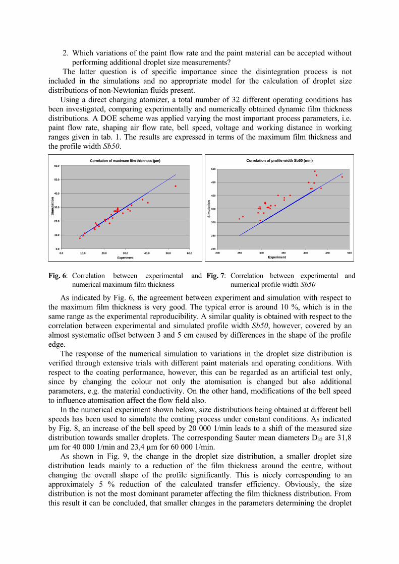
Using a direct charging atomizer, a total number of 32 different operating conditions has been investigated, comparing experimentally and numerically obtained dynamic film thickness distributions. A DOE scheme was applied varying the most important process parameters, i.e. paint flow rate, shaping air flow rate, bell speed, voltage and working distance in working ranges given in tab. 1. The results are expressed in terms of the maximum film thickness and the profile width Sb50.
Fig. 6: Correlation between experimental and numerical maximum film thickness
Fig. 7: Correlation between experimental and numerical profile width Sb50
As indicated by Fig. 6, the agreement between experiment and simulation with respect to the maximum film thickness is very good. The typical error is around 10 %, which is in the same range as the experimental reproducibility. A similar quality is obtained with respect to the correlation between experimental and simulated profile width Sb50, however, covered by an almost systematic offset between 3 and 5 cm caused by differences in the shape of the profile edge.
The response of the numerical simulation to variations in the droplet size distribution is verified through extensive trials with different paint materials and operating conditions. With respect to the coating performance, however, this can be regarded as an artificial test only, since by changing the colour not only the atomisation is changed but also additional parameters, e.g. the material conductivity. On the other hand, modifications of the bell speed to influence atomisation affect the flow field also.
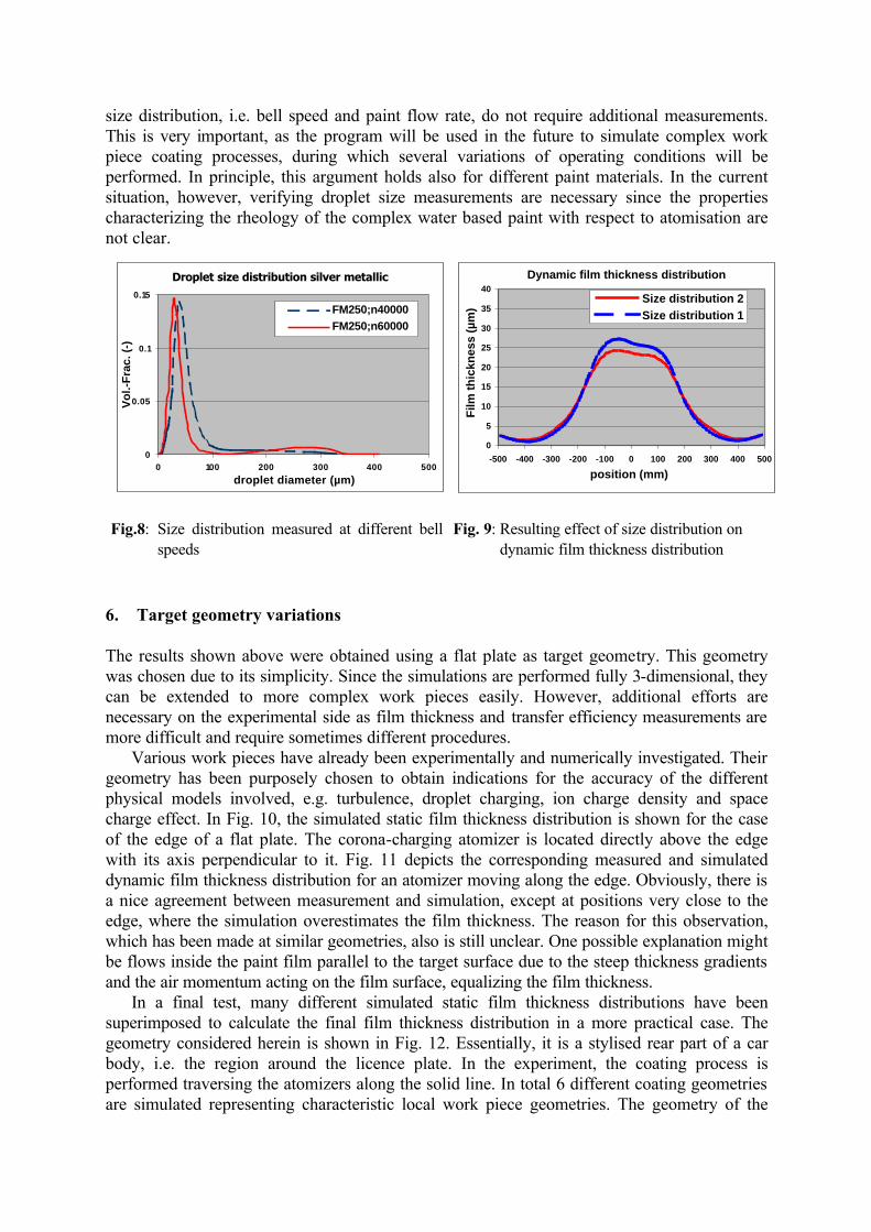
In the numerical experiment shown below, size distributions being obtained at different bell speeds has been used to simulate the coating process under constant conditions. As indicated by Fig. 8, an increase of the bell speed by 20 000 1/min leads to a shift of the measured size distribution towards smaller droplets. The corresponding Sauter mean diameters D32 are 31,8 µm for 40 000 1/min and 23,4 µm for 60 000 1/min.
As shown in Fig. 9, the change in the droplet size distribution, a smaller droplet size distribution leads mainly to a reduction of the film thickness around the centre, without changing the overall shape of the profile significantly. This is nicely corresponding to an approximately 5 % reduction of the calculated transfer efficiency. Obviously, the size distribution is not the most dominant parameter affecting the film thickness distribution. From this result it can be concluded, that smaller changes in the parameters determining the droplet
Correlation of profile width Sb50 (mm)
200
250
300
350
400
450
500
200 250 300 350 400 450 500
Experiment
Sim
ula
tio
n
Correlation of maximum film thickness (µm)
0.0
10.0
20.0
30.0
40.0
50.0
60.0
0.0 10.0 20.0 30.0 40.0 50.0 60.0
Experiment
Sim
ula
tio
n
size distribution, i.e. bell speed and paint flow rate, do not require additional measurements. This is very important, as the program will be used in the future to simulate complex work piece coating processes, during which several variations of operating conditions will be performed. In principle, this argument holds also for different paint materials. In the current situation, however, verifying droplet size measurements are necessary since the properties characterizing the rheology of the complex water based paint with respect to atomisation are not clear.
Droplet size distribution silver metallic
0
0.05
0.1
0.15
0 100 200 300 400 500
droplet diameter (µm)
Vo
l.-F
rac.
(-)
FM250;n40000FM250;n60000
Dynamic film thickness distribution
0
5
10
15
20
25
30
35
40
-500 -400 -300 -200 -100 0 100 200 300 400 500
position (mm)F
ilm th
ickn
ess
(µm
)
Size distribution 2Size distribution 1
Fig.8: Size distribution measured at different bell
speeds Fig. 9: Resulting effect of size distribution on
dynamic film thickness distribution 6. Target geometry variations The results shown above were obtained using a flat plate as target geometry. This geometry was chosen due to its simplicity. Since the simulations are performed fully 3-dimensional, they can be extended to more complex work pieces easily. However, additional efforts are necessary on the experimental side as film thickness and transfer efficiency measurements are more difficult and require sometimes different procedures.
Various work pieces have already been experimentally and numerically investigated. Their geometry has been purposely chosen to obtain indications for the accuracy of the different physical models involved, e.g. turbulence, droplet charging, ion charge density and space charge effect. In Fig. 10, the simulated static film thickness distribution is shown for the case of the edge of a flat plate. The corona-charging atomizer is located directly above the edge with its axis perpendicular to it. Fig. 11 depicts the corresponding measured and simulated dynamic film thickness distribution for an atomizer moving along the edge. Obviously, there is a nice agreement between measurement and simulation, except at positions very close to the edge, where the simulation overestimates the film thickness. The reason for this observation, which has been made at similar geometries, also is still unclear. One possible explanation might be flows inside the paint film parallel to the target surface due to the steep thickness gradients and the air momentum acting on the film surface, equalizing the film thickness.
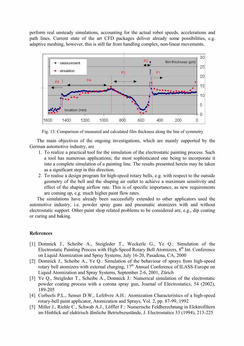
In a final test, many different simulated static film thickness distributions have been superimposed to calculate the final film thickness distribution in a more practical case. The geometry considered herein is shown in Fig. 12. Essentially, it is a stylised rear part of a car body, i.e. the region around the licence plate. In the experiment, the coating process is performed traversing the atomizers along the solid line. In total 6 different coating geometries are simulated representing characteristic local work piece geometries. The geometry of the

coating process, i.e. the path line of the atomizer along the work piece surface, corresponds to the practical application. The result in terms of the comparison between experimental and simulation film thickness along the line of symmetry of the geometry (dashed line) is shown in Fig. 13. The notation P1 to P5 given in Fig. 13 corresponds to panel 1 to panel 5 as indicated in Fig. 12. For clarity, the panels are arranged to lie in one plane.
Dynamic film thickness distribution
0
5
10
15
20
25
0 100 200 300 400 500position (mm)
film
thic
knes
s (µ
m)
measurement
simulation
panel edge
Fig. 10: Simulation of the static coating process
of the edge of a flat plate (corona charging)
Fig. 11: Comparison of measured and simulated dynamic film thickness distribution
In this test, which clearly demonstrates the usefulness of the developed program for the
practical application, the differences in the local film thicknesses are usually below 2 µm, which is close to the measurement accuracy. Although this result is very encouraging, it should be noted that the computational efforts are still too high. On a standard PC, the actual computation time per static distribution is between 1 and 2 days without the required CAD-work to prepare the geometry. A future speed up might be possible by using more powerful computers and, at the same time, by implementing faster and simpler models for
the processes involved. 7. Summary and Outlook The present contribution summarizes the state of the art of the investigations performed at the IPA to simulate the electrostatically supported spray painting process with high-speed rotary bell atomizers using both direct charging and corona charging. Measured and simulated static film thickness distributions are already in good agreement, which applies not only to flat geometries but also more complex work pieces. Consequently, this result applies also to the dynamic profiles, which are derived through a relatively simple integration procedure. In general, arbitrarily shaped work pieces can be coated, if an appropriate number of static cases are simulated, numerically integrated along the direction of propagation and finally superimposed. In short term, this might be the solution, but in long term it is necessary to
Fig. 12: Coating process of a stylised car body
rear part
perform real unsteady simulations, accounting for the actual robot speeds, accelerations and path lines. Current state of the art CFD packages deliver already some possibilities, e.g. adaptive meshing, however, this is still far from handling complex, non-linear movements.
The main objectives of the ongoing investigations, which are mainly supported by the German automotive industry, are
1. To realize a practical tool for the simulation of the electrostatic painting process. Such a tool has numerous applications; the most sophisticated one being to incorporate it into a complete simulation of a painting line. The results presented herein may be taken as a significant step in this direction.
2. To realise a design program for high-speed rotary bells, e.g. with respect to the outside geometry of the bell and the shaping air outlet to achieve a maximum sensitivity and effect of the shaping airflow rate. This is of specific importance, as new requirements are coming up, e.g. much higher paint flow rates.
The simulations have already been successfully extended to other applicators used the automotive industry, i.e. powder spray guns and pneumatic atomizers with and without electrostatic support. Other paint shop related problems to be considered are, e.g., dip coating or curing and baking. References [1] Domnick J., Scheibe A., Steigleder T., Weckerle G., Ye Q.: Simulation of the
Electrostatic Painting Process with High-Speed Rotary Bell Atomizers, 8th Int. Conference on Liquid Atomization and Spray Systems, July 16-20, Pasadena, CA, 2000
[2] Domnick J., Scheibe A., Ye Q.: Simulation of the behaviour of sprays from high-speed rotary bell atomizers with external charging, 17th Annual Conference of ILASS-Europe on Liquid Atomization and Spray Systems, September 2-6, 2001, Zürich
[3] Ye Q., Steigleder T., Scheibe A., Domnick J.: Numerical simulation of the electrostatic powder coating process with a corona spray gun, Journal of Electrostatics, 54 (2002), 189-205
[4] Corbeels P.L., Senser D.W., Lefebvre A.H.: Atomization Characteristics of a high-speed rotary-bell paint applicator, Atomization and Sprays, Vol. 2, pp. 87-99, 1992
[5] Miller J., Riehle C., Schwab A.J., Löffler F.: Numerische Feldberechnung in Elektrofiltern im Hinblick auf elektrisch ähnliche Betriebszustände, J. Electrostatics 33 (1994), 213-225
Fig. 13: Comparison of measured and calculated film thickness along the line of symmetry

[6] Pauthenier M.M. and Moreau-Hanot, M.: La Charge des particules sphérique dans un champs ionise, J. d’Physique Radium 7 (1932), 590-613
[7] Domnick J and Ye Q: On the simulation of space charge in electrostatic powder coating with a corona spray gun, submitted for Powder Technology, 2002
[8] Soldati A.: On the effects of the electrohydrodynamic flows and turbulence on aerosol transport and collection in wire-plate electrostatic precipitators, J. Aerosol Sci., Vol. 31, 3, pp. 293-305, 2000